JP7279043B2 - Filter connection for smoke evacuator - Google Patents
Filter connection for smoke evacuatorDownload PDFInfo
- Publication number
- JP7279043B2 JP7279043B2JP2020529383AJP2020529383AJP7279043B2JP 7279043 B2JP7279043 B2JP 7279043B2JP 2020529383 AJP2020529383 AJP 2020529383AJP 2020529383 AJP2020529383 AJP 2020529383AJP 7279043 B2JP7279043 B2JP 7279043B2
- Authority
- JP
- Japan
- Prior art keywords
- socket
- filter
- canister
- filter canister
- connection
- Prior art date
- Legal status (The legal status is an assumption and is not a legal conclusion. Google has not performed a legal analysis and makes no representation as to the accuracy of the status listed.)
- Active
Links
Images


Classifications
- A—HUMAN NECESSITIES
- A61—MEDICAL OR VETERINARY SCIENCE; HYGIENE
- A61B—DIAGNOSIS; SURGERY; IDENTIFICATION
- A61B18/00—Surgical instruments, devices or methods for transferring non-mechanical forms of energy to or from the body
- A61B18/04—Surgical instruments, devices or methods for transferring non-mechanical forms of energy to or from the body by heating
- A61B18/12—Surgical instruments, devices or methods for transferring non-mechanical forms of energy to or from the body by heating by passing a current through the tissue to be heated, e.g. high-frequency current
- A61B18/14—Probes or electrodes therefor
- B—PERFORMING OPERATIONS; TRANSPORTING
- B01—PHYSICAL OR CHEMICAL PROCESSES OR APPARATUS IN GENERAL
- B01D—SEPARATION
- B01D46/00—Filters or filtering processes specially modified for separating dispersed particles from gases or vapours
- B01D46/0002—Casings; Housings; Frame constructions
- B01D46/0005—Mounting of filtering elements within casings, housings or frames
- B—PERFORMING OPERATIONS; TRANSPORTING
- B01—PHYSICAL OR CHEMICAL PROCESSES OR APPARATUS IN GENERAL
- B01D—SEPARATION
- B01D46/00—Filters or filtering processes specially modified for separating dispersed particles from gases or vapours
- B01D46/0002—Casings; Housings; Frame constructions
- B01D46/0012—In-line filters
- B—PERFORMING OPERATIONS; TRANSPORTING
- B01—PHYSICAL OR CHEMICAL PROCESSES OR APPARATUS IN GENERAL
- B01D—SEPARATION
- B01D46/00—Filters or filtering processes specially modified for separating dispersed particles from gases or vapours
- B01D46/0039—Filters or filtering processes specially modified for separating dispersed particles from gases or vapours with flow guiding by feed or discharge devices
- B01D46/0041—Filters or filtering processes specially modified for separating dispersed particles from gases or vapours with flow guiding by feed or discharge devices for feeding
- B01D46/0043—Filters or filtering processes specially modified for separating dispersed particles from gases or vapours with flow guiding by feed or discharge devices for feeding containing fixed gas displacement elements or cores
- B—PERFORMING OPERATIONS; TRANSPORTING
- B01—PHYSICAL OR CHEMICAL PROCESSES OR APPARATUS IN GENERAL
- B01D—SEPARATION
- B01D46/00—Filters or filtering processes specially modified for separating dispersed particles from gases or vapours
- B01D46/24—Particle separators, e.g. dust precipitators, using rigid hollow filter bodies
- F—MECHANICAL ENGINEERING; LIGHTING; HEATING; WEAPONS; BLASTING
- F24—HEATING; RANGES; VENTILATING
- F24F—AIR-CONDITIONING; AIR-HUMIDIFICATION; VENTILATION; USE OF AIR CURRENTS FOR SCREENING
- F24F8/00—Treatment, e.g. purification, of air supplied to human living or working spaces otherwise than by heating, cooling, humidifying or drying
- F24F8/10—Treatment, e.g. purification, of air supplied to human living or working spaces otherwise than by heating, cooling, humidifying or drying by separation, e.g. by filtering
- H—ELECTRICITY
- H01—ELECTRIC ELEMENTS
- H01R—ELECTRICALLY-CONDUCTIVE CONNECTIONS; STRUCTURAL ASSOCIATIONS OF A PLURALITY OF MUTUALLY-INSULATED ELECTRICAL CONNECTING ELEMENTS; COUPLING DEVICES; CURRENT COLLECTORS
- H01R13/00—Details of coupling devices of the kinds covered by groups H01R12/70 or H01R24/00 - H01R33/00
- H01R13/005—Electrical coupling combined with fluidic coupling
- A—HUMAN NECESSITIES
- A61—MEDICAL OR VETERINARY SCIENCE; HYGIENE
- A61B—DIAGNOSIS; SURGERY; IDENTIFICATION
- A61B18/00—Surgical instruments, devices or methods for transferring non-mechanical forms of energy to or from the body
- A61B18/04—Surgical instruments, devices or methods for transferring non-mechanical forms of energy to or from the body by heating
- A61B18/12—Surgical instruments, devices or methods for transferring non-mechanical forms of energy to or from the body by heating by passing a current through the tissue to be heated, e.g. high-frequency current
- A61B18/1206—Generators therefor
- A—HUMAN NECESSITIES
- A61—MEDICAL OR VETERINARY SCIENCE; HYGIENE
- A61B—DIAGNOSIS; SURGERY; IDENTIFICATION
- A61B18/00—Surgical instruments, devices or methods for transferring non-mechanical forms of energy to or from the body
- A61B2018/00053—Mechanical features of the instrument of device
- A61B2018/00172—Connectors and adapters therefor
- A61B2018/00178—Electrical connectors
- A—HUMAN NECESSITIES
- A61—MEDICAL OR VETERINARY SCIENCE; HYGIENE
- A61B—DIAGNOSIS; SURGERY; IDENTIFICATION
- A61B18/00—Surgical instruments, devices or methods for transferring non-mechanical forms of energy to or from the body
- A61B2018/00571—Surgical instruments, devices or methods for transferring non-mechanical forms of energy to or from the body for achieving a particular surgical effect
- A61B2018/00595—Cauterization
- A—HUMAN NECESSITIES
- A61—MEDICAL OR VETERINARY SCIENCE; HYGIENE
- A61B—DIAGNOSIS; SURGERY; IDENTIFICATION
- A61B18/00—Surgical instruments, devices or methods for transferring non-mechanical forms of energy to or from the body
- A61B2018/00571—Surgical instruments, devices or methods for transferring non-mechanical forms of energy to or from the body for achieving a particular surgical effect
- A61B2018/00601—Cutting
- A—HUMAN NECESSITIES
- A61—MEDICAL OR VETERINARY SCIENCE; HYGIENE
- A61B—DIAGNOSIS; SURGERY; IDENTIFICATION
- A61B2218/00—Details of surgical instruments, devices or methods for transferring non-mechanical forms of energy to or from the body
- A61B2218/001—Details of surgical instruments, devices or methods for transferring non-mechanical forms of energy to or from the body having means for irrigation and/or aspiration of substances to and/or from the surgical site
- A61B2218/007—Aspiration
- A61B2218/008—Aspiration for smoke evacuation
- B—PERFORMING OPERATIONS; TRANSPORTING
- B01—PHYSICAL OR CHEMICAL PROCESSES OR APPARATUS IN GENERAL
- B01D—SEPARATION
- B01D2265/00—Casings, housings or mounting for filters specially adapted for separating dispersed particles from gases or vapours
- B01D2265/02—Non-permanent measures for connecting different parts of the filter
- B01D2265/024—Mounting aids
- B01D2265/026—Mounting aids with means for avoiding false mounting
- B—PERFORMING OPERATIONS; TRANSPORTING
- B01—PHYSICAL OR CHEMICAL PROCESSES OR APPARATUS IN GENERAL
- B01D—SEPARATION
- B01D2271/00—Sealings for filters specially adapted for separating dispersed particles from gases or vapours
- B01D2271/02—Gaskets, sealings
- B01D2271/027—Radial sealings
- B—PERFORMING OPERATIONS; TRANSPORTING
- B01—PHYSICAL OR CHEMICAL PROCESSES OR APPARATUS IN GENERAL
- B01D—SEPARATION
- B01D2279/00—Filters adapted for separating dispersed particles from gases or vapours specially modified for specific uses
- B01D2279/35—Filters adapted for separating dispersed particles from gases or vapours specially modified for specific uses for venting arrangements
Landscapes
- Chemical & Material Sciences (AREA)
- Engineering & Computer Science (AREA)
- Chemical Kinetics & Catalysis (AREA)
- Health & Medical Sciences (AREA)
- Life Sciences & Earth Sciences (AREA)
- Surgery (AREA)
- Combustion & Propulsion (AREA)
- Mechanical Engineering (AREA)
- General Engineering & Computer Science (AREA)
- Otolaryngology (AREA)
- Molecular Biology (AREA)
- Plasma & Fusion (AREA)
- Physics & Mathematics (AREA)
- Biomedical Technology (AREA)
- Heart & Thoracic Surgery (AREA)
- Medical Informatics (AREA)
- Nuclear Medicine, Radiotherapy & Molecular Imaging (AREA)
- Animal Behavior & Ethology (AREA)
- General Health & Medical Sciences (AREA)
- Public Health (AREA)
- Veterinary Medicine (AREA)
- Filtering Of Dispersed Particles In Gases (AREA)
- Surgical Instruments (AREA)
Description
Translated fromJapanese本開示は、電気外科用システムで使用される排煙システムに関する。より具体的には、本開示は、排煙システムにおいてフィルタを接続する機器及び方法に関する。 The present disclosure relates to smoke evacuation systems for use with electrosurgical systems. More specifically, the present disclosure relates to apparatus and methods for connecting filters in smoke evacuation systems.
当業者には知られているように、現代の外科技術では、通常、組織を切断し、外科手技を実施する上で直面する出血を凝固させるために、高周波(radio frequency、RF)電力が用いられている。このような電気外科手術は広く使用されており、切断及び凝固両方のための単一の外科器具の使用を含む、多くの利点をもたらしている。単極の電気外科用発生器システムは、ハンドピース及び導電性電極又はチップを有する電気外科用器具などの形態をなし、手術を実施するために手術部位で外科医によって患者に適用される活性電極と、患者を再び発生器に接続するためのリターン電極と、を有する。 As is known to those skilled in the art, modern surgical techniques typically employ radio frequency (RF) power to cut tissue and coagulate bleeding encountered in performing surgical procedures. It is Such electrosurgery is widely used and offers many advantages, including the use of a single surgical instrument for both cutting and coagulation. A monopolar electrosurgical generator system takes the form of an electrosurgical instrument having a handpiece and an electrically conductive electrode or tip, along with an active electrode that is applied to the patient by the surgeon at the surgical site to perform surgery. , a return electrode for connecting the patient back to the generator.
電気外科用器具の電極又はチップは、焼灼によって組織を切断する又は凝固させる外科的効果を生み出すために、高度な電流密度を有する高周波電流を発生させるように、患者との接触点においては小さいものとなっている。リターン電極は、電気外科用器具の電極又はチップに供給される高周波信号と同じ高周波信号を搬送し、それが患者を通過した後、電気外科用発生器に戻る経路を提供する。 The electrodes or tips of electrosurgical instruments are small at the point of contact with the patient so as to generate high frequency currents with high current densities to produce the surgical effect of cutting or coagulating tissue by cauterization. It has become. The return electrode carries the same high frequency signal that is supplied to the electrode or tip of the electrosurgical instrument and provides a path back to the electrosurgical generator after it has passed through the patient.
電気外科用器具は、組織を切断するために、並びに/又は標的組織の中及び/若しくは付近の血管を焼灼するために、患者の標的組織に電気エネルギーを伝達する。この切断/焼灼は、結果として煙が空気中に放出されることになり、これは不快でかつ/又は施術者の視界の障害となり得る。したがって、多くの電気外科用システムは、発生する煙を捕捉し、それを、施術者及び/又は患者から離れるようにフィルタ及び排気ポートを通して誘導する、排煙システムを採用し得る。 Electrosurgical instruments deliver electrical energy to target tissue of a patient to cut tissue and/or cauterize blood vessels in and/or near the target tissue. This cutting/cautery results in the release of smoke into the air, which can be uncomfortable and/or impair the operator's vision. Accordingly, many electrosurgical systems may employ smoke evacuation systems that capture the smoke that is generated and direct it through filters and exhaust ports away from the practitioner and/or patient.
排煙システムは通常、ポンプとフィルタとを備える。ポンプは、真空管を通じてフィルタの中へと煙を引き込む吸引作用を発生させる。真空管は、ハンドピースにおいて煙が吸引されるように、電極チップを含むハンドピースで終端してよい。他の電気外科用システムは、煙をシステムの中へと吸引するために使用される別個のハンドピースを含むこともある。煙は真空管を介してフィルタへと進行し、また、煙がフィルタを通って移動する際に、不快な臭いが濾過される。次いで、濾過された空気は、排気として排煙システムから出ることができる。 A smoke evacuation system typically comprises a pump and a filter. The pump creates suction that draws the smoke through the vacuum tube and into the filter. The vacuum tube may terminate in a handpiece that includes an electrode tip such that smoke is drawn into the handpiece. Other electrosurgical systems may include a separate handpiece that is used to draw smoke into the system. The smoke travels through the vacuum tube to the filter, and unpleasant odors are filtered as the smoke travels through the filter. The filtered air can then exit the smoke extraction system as exhaust.
本明細書において特許請求される主題は、いずれかの不利益を解消するか、又は上述したような環境においてのみ動作する実施形態に限定されるものではない。むしろ、この背景技術は単に、本明細書に記載されるいくつかの実施形態が実施され得る、1つの代表的な技術分野を例示するために提示される。 The subject matter claimed herein is not limited to embodiments that eliminate any disadvantages or that operate only in environments such as those described above. Rather, this background is merely presented to illustrate one representative technical area in which some embodiments described herein may be implemented.
本開示は排煙システムに関する。より具体的には、本開示は、排煙装置のためのフィルタ接続部に関する。フィルタを排煙システム内で交換することが必要となる時期を判定することは困難となり得、また現行のフィルタ接続部は、誤った取り付けにつながり得る。本開示のフィルタ接続部は、フィルタの容易な取り付けを可能にするだけでなく、フィルタを交換する必要があるとき又は間違ったフィルタが取り付けられているときに電子的に検出及び通知するその他の特徴も可能にし得る。 The present disclosure relates to smoke evacuation systems. More specifically, the present disclosure relates to filter connections for smoke evacuators. Determining when a filter needs to be replaced in a smoke evacuation system can be difficult, and current filter connections can lead to incorrect installation. The filter connections of the present disclosure not only allow easy installation of filters, but also other features that electronically detect and notify when a filter needs to be replaced or the wrong filter is installed. can also make it possible.
一実施形態において、排煙システムのためのフィルタ接続部は、フィルタキャニスタとソケットとを含む。フィルタキャニスタは、第1及び第2の端部と、第1の端部と第2の端部との間に延在する本体と、接続ニップルと、接続ニップルの周りに配設されたシールと、第1の電子コネクタと、を備える。ソケットは、キャニスタ本体を受容するように構成された第1の凹部と、接続ニップルを受容するように構成された第2の凹部と、第2の電子コネクタと、を備える。シールと第1の電子コネクタとの間の長手方向距離は、ソケットの第2の凹部と第2の電子コネクタとの間の長手方向距離よりも長い。 In one embodiment, a filter connection for a smoke evacuation system includes a filter canister and a socket. The filter canister has first and second ends, a body extending between the first and second ends, a connecting nipple, and a seal disposed about the connecting nipple. , and a first electronic connector. The socket includes a first recess configured to receive the canister body, a second recess configured to receive the connection nipple, and a second electronic connector. A longitudinal distance between the seal and the first electronic connector is greater than a longitudinal distance between the second recess of the socket and the second electronic connector.
一実施形態において、排煙システムのためのフィルタキャニスタは、入口ポートを有する第1の端部と、第2の端部と、電子コネクタと、第2の端部に配設された接続ニップルと、を含む。フィルタキャニスタの第2の端部の断面形状は、1つのみの対称線を有する。電子コネクタは、フィルタキャニスタの第2の端部に配設されている。 In one embodiment, a filter canister for a smoke evacuation system includes a first end having an inlet port, a second end, an electronic connector, and a connection nipple disposed at the second end. ,including. The cross-sectional shape of the second end of the filter canister has only one line of symmetry. An electronic connector is disposed on the second end of the filter canister.
一実施形態において、排煙システム内でフィルタを接続するための方法は、以下の工程、すなわち、フィルタキャニスタを供給することと、排煙システム内にソケットを供給することと、フィルタキャニスタがフィルタキャニスタとソケットとの間に気密な境界を形成するように、フィルタキャニスタをソケットの中に第1の距離だけ挿入することと、フィルタキャニスタとソケットとの間に電子接続が形成されるように、フィルタキャニスタをソケットの中に第2の距離だけ挿入することと、を含む。第2距離は第1距離よりも長い。 In one embodiment, a method for connecting a filter within a smoke evacuation system includes the following steps: providing a filter canister; providing a socket within the smoke evacuation system; inserting the filter canister into the socket a first distance to form an airtight boundary between the filter canister and the socket; inserting the canister into the socket a second distance. The second distance is longer than the first distance.
この「発明の概要」は、「発明を実施するための形態」において以下に更に説明される簡潔な形態で概念の選択を紹介するために提供される。この「発明の概要」は、特許請求対象の主要な特徴又は必須の特徴を特定することを意図するものではなく、また特許請求対象の範囲を決定する際の補助として使用されることも意図していない。 This Summary of the Invention is provided to introduce a selection of concepts in a simplified form that are further described below in the Detailed Description. This Summary of the Invention is not intended to identify key features or essential features of the claimed subject matter, nor is it intended to be used as an aid in determining the scope of the claimed subject matter. not
開示される実施形態の更なる特徴及び利点は、以下の説明に記載され、一部はその説明から明らかとなるか、又は本開示の実践によって習得され得る。これらの及びその他の特徴は、以下の説明及び添付の特許請求の範囲からより完全に明らかとなるか、又は本開示の実践によって習得され得る。 Additional features and advantages of the disclosed embodiments will be set forth in the description that follows, and in part will be apparent from the description, or may be learned by practice of the disclosure. These and other features will become more fully apparent from the ensuing description and appended claims, or may be learned by practice of the present disclosure.
本発明の上記の及びその他の利点及び特徴を更に明確にするために、本発明のより具体的な説明が、添付の図面に例示されるその特定の実施形態を参照することによって提供される。これらの図面は、本発明の単なる例示の実施形態を描くものであり、したがって、その範囲を限定するものとみなされるものではないことが理解される。本発明は、以下の添付図面の使用により、更に特異的かつ詳細に記載及び説明される。
本開示は排煙システムに関する。より具体的には、本開示は、排煙装置のためのフィルタ接続部に関する。フィルタを排煙システム内で交換することが必要となる時期を判定することは困難となることがあり、また現行のフィルタ接続部は、誤った取り付けにつながり得る。本開示のフィルタ接続部は、フィルタを容易に取り付けることを可能にするだけでなく、フィルタを交換する必要があること又は間違ったフィルタが取り付けられていることを電子的に検出及び通知するためのその他の機構も可能にし得る。 The present disclosure relates to smoke evacuation systems. More specifically, the present disclosure relates to filter connections for smoke evacuators. Determining when a filter needs to be replaced in a smoke evacuation system can be difficult, and current filter connections can lead to incorrect installation. The filter connection of the present disclosure not only allows for easy filter installation, but also provides electronic detection and notification that the filter needs to be replaced or that the wrong filter has been installed. Other mechanisms may also be possible.
図1は例示的な電気外科用システム100を示している。図示される実施形態は、信号発生器102と、電気外科用器具104と、リターン電極106と、排煙システム120と、を含む。発生器102は、一実施形態では、高周波電気エネルギーを生成する高周波発生器である。電気外科用器具104には、ユーティリティ導管108が連結されている。図示される実施形態では、ユーティリティ導管108は、発生器102から電気外科用器具104に電気エネルギーを伝達するケーブル110を含む。図示されるユーティリティ導管108はまた、捕捉及び/又は収集された煙及び/又は流体を手術部位から離れる方向に搬送する真空ホース112を含む。 FIG. 1 shows an exemplary
一般に、電気外科用器具104は、ハンドピース又はペンシル114と、電極チップ116と、を含む。電気外科用器具104は、組織を切断するために、並びに/又は標的組織の中及び/若しくは付近の血管を焼灼するために、患者の標的組織に電気エネルギーを伝達する。具体的に言えば、電極チップ116に密着又は隣接した患者の細胞物質の加熱を引き起こすために、放電が電極チップ116から患者に送達される。組織の加熱は、電気外科用器具104を使用して電気外科手術を実施することが可能となるように、適度に高い温度で生じる。回路を完成させ、かつ患者の身体に進入するエネルギーのための波形発生器102への帰還電気経路を設けるために、リターン電極106がケーブル118によって発生器102に接続され、(リターン電極のタイプに応じて)患者に適用されるかあるいは患者に近接して配置される。
電極チップ116による患者の細胞物質の加熱、又は出血を防ぐための血管の焼灼は、結果として、焼灼が行われるところで煙を放出させることになる。電気外科用器具104は、処置中に放出される煙を捕捉することが可能となるように、電極チップ116付近に排煙導管開口部122を備えてもよい。真空吸引によって、煙は、電気外科用器具104を通じて導管開口部122の中へ、また排煙システム120に向かって真空ホース112の中へと引き込まれ得る。 Heating of the patient's cellular material by the
図2は、排煙システム300の一実施形態を示す。排煙システム300は、フィルタ306と、空気流経路308と、を含み得る。空気流経路308は、空気流経路308と直列に配置されたポンプ310を備えてもよく、このポンプは、機械的動作によって空気流経路308内に圧力差を発生させる。この圧力差は、空気流経路308を通るガスの移動を引き起こし得る。空気流経路308を通じて引き込まれるガスは煙302であってもよく、あるいは、煙302がフィルタ306を通過した後に残留する濾過空気であってもよい。モータ312がポンプ310を駆動する。 FIG. 2 illustrates one embodiment of a
排煙システム300はまた、同様に空気流経路308と直列に配設され得る排気機構314を含んでもよい。排気機構314は、出口ポート324において排煙システム300から出る濾過されたガス304の速度、方向、及び/又はその他の特性を制御する機構であり得る。
空気流経路308は、入口ポート322と出口ポート324との間に配設され得る。煙302は、入口ポート322においてフィルタ306に流入し、ポンプ310によって空気流経路308を通じてポンプ圧送され得、その結果、煙302は、フィルタ306を通り、また排気機構314を通じて、排煙システム300の出口ポート324の外へと引き込まれる。出口ポート324において排煙システム300から出る空気は、排気304であり得る。排気304は、排煙システム300を通過し、出口ポート324を通って出る濾過された空気/ガスからなり得る。
空気流経路308は、第1のゾーン316と、第2のゾーン318と、を含み得る。第1のゾーン316はポンプ306の上流側にあってよく、第2のゾーン318はポンプ306の下流側にあってよい。ポンプ306は、第2のゾーン318内の空気が第1のゾーン316内の空気よりも高い圧力を有するように、空気流経路308内の空気を加圧することができる。
排煙システム300はまた、ハウジング320を含んでもよい。図2は、ハウジング320内の様々な構成要素を示すために、排煙システム300の断面図を示す。ハウジング320は、排煙システム300を完全に包囲してもよいし、部分的に包囲してもよい。空気流経路308は、空気流経路308を通って移動する空気を実質的に収容し、かつ/又は空気流経路308の外側の空気から分離する、管又は他の導管から少なくとも部分的に構成されてもよい。
例えば、空気流経路308の第1のゾーン316は、空気流経路308がフィルタ306とポンプ310との間に延在する管を含んでよい。空気流経路308の第2のゾーン318も、空気流経路308がポンプ310と排気機構314との間に延在する管を含んでよい。空気流経路308はまた、連続的な空気流経路308が入口ポート322から出口ポート324まで延在するように、フィルタ306、ポンプ310、及び排気機構314を通じて延在する。 For example,
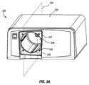
図3Aは、排煙システム300の斜視図を示す。排煙システム300は、フィルタ306を受容するように構成されたソケット326を含んでもよい。フィルタ306は、ソケット326を図示するために、図3には示されていない。ソケット326は、第1の凹部328と、第2の凹部332と、を有し得る。移行表面330は、第1の凹部328と第2の凹部332との間に延在する。フィルタ306がソケット326の中にぴったりと嵌合するように、ソケット326は、ソケットの中にフィルタ306を受容するように成形され得る。 FIG. 3A shows a perspective view of
図3Bは、図3Aの排煙システム300の断面図を示す。図3Bは、ソケット326を通過する、図3Aに示される平面334の断面図を示す。図3Bに示されるように、ソケットは、フィルタ306を受容するように開口した第1の端部336と、空気流経路308と連通している第2の端部338と、を備える。フィルタ306は、ソケット326の第1の端部336に挿入され、また第1の端部から取り外され得る。 FIG. 3B shows a cross-sectional view of the
ソケット326はまた、フィルタキャニスタアセンブリの第2の端部を受容するように構成された移行表面330と、接続ニップルを受容するように構成された第2の凹部332と、電子コネクタ340と、を含み得る。本体、第2の端部、接続ニップル、及び電子コネクタを含むフィルタキャニスタアセンブリに関する更なる詳細が、以下に示される。 The
図4A~4Cは、フィルタキャニスタアセンブリ342の一実施形態の様々な図を示す。図4Aは、フィルタキャニスタアセンブリ342の斜視図を示す。フィルタキャニスタアセンブリ342は、第1の端部344と、第2の端部346と、を含み得る。フィルタキャニスタ342の第2の端部346は、少なくとも部分的に円錐状であってよい。キャニスタ本体348は、キャニスタアセンブリ342の第1の端部344と第2の端部346との間に配設され得る。フィルタキャニスタアセンブリ342は、排煙システム300のソケット326の中に挿入されるように構成され得る。 4A-4C show various views of one embodiment of
キャニスタアセンブリ342がソケット326の中に過度に深く挿入され得ないように、プレート350がキャニスタアセンブリ342の第1の端部344上に配設されてもよい。キャニスタアセンブリ342がソケット326の中に完全に挿入されると、プレート350は外側ハウジング320と接触し、かつ/又はキャニスタアセンブリ342の第2の端部346はソケット326の移行表面330に当接し、その結果、キャニスタアセンブリ342は更に挿入され得ない。キャニスタアセンブリ342の第2の端部346及び本体348は、ソケット326の中に嵌合することが可能であってよいが、プレート350はそうでなくてもよい。キャニスタアセンブリ342は、プレート350が排煙システム300の外側ハウジング320と接触するまで挿入され得る。プレート350は、図2を参照して上述された入口ポート322などの入口ポート322を含み得る。図1に示される真空ホース112は、入口ポート322と接続してもよく、これにより、煙は真空ホース112を通じて進行し、また入口ポート322においてフィルタキャニスタアセンブリ324の中へと進行することができる。 A
煙は入口ポート322から進入し、フィルタキャニスタアセンブリ342の本体348内に配設されたフィルタ306の内側経路を通って移動し得る。煙がフィルタ306を通って移動する際に、潜在的に有害及び/又は不快である毒素及び微粒子がフィルタ306内に捕捉され得る。濾過後に残留している濾過されたガスは、図4Bに示されるキャニスタ出口352を通ってフィルタキャニスタアセンブリ342から出ることができる。キャニスタ出口352が空気流経路308と連通するように、フィルタキャニスタアセンブリ342は、排煙システム300のソケット326の中に挿入され得る。 Smoke may enter through
図4Bは、フィルタキャニスタアセンブリ342の第2の端部346の斜視図を示す。第2の端部346は、キャニスタ出口352を囲繞する接続ニップル354と、第1の電子コネクタ356と、を含み得る。一実施形態において、第1の電子コネクタは、消去可能なプログラマブル読み出し専用メモリ(EPROM)コネクタであり得る。第1の電子プログラマブルコネクタ356は、雄コネクタであってよい。他の実施形態は、雌コネクタである第1の電子プログラマブルコネクタを含んでもよい。キャニスタアセンブリ342の第2の端部346はまた、接続ニップル354の周りに配設されたシール358を含んでよい。接続ニップル354、シール358、及び電子プログラマブルコネクタ356に関する更なる詳細は、図6A及び図6Bを参照して以下に示される。 FIG. 4B shows a perspective view of
図5Aは、フィルタキャニスタ360の第2の端部の断面形状、及びソケット361の第1の凹部の断面形状を示す。フィルタキャニスタ360の第2の端部の断面形状は、ソケット361の第1の凹部の断面形状と同様かつわずかに小さくてよく、その結果、フィルタキャニスタアセンブリ360は、挿入されるとソケット361にぴったりと嵌合することができる。キャニスタアセンブリ360の第2の端部の断面形状は、ソケット361の第1の凹部の断面形状よりもわずかに小さくてよく、その結果、フィルタキャニスタ360をその中に挿入することができる。 FIG. 5A shows the cross-sectional shape of the second end of
図5Aは、涙滴形状の断面360、361を示す。涙滴断面形状360、361は、フィルタキャニスタ360がソケット361の中に嵌合するように、フィルタキャニスタ360が特定の向きでのみ挿入され得ることを確実にすることができる。他の実施形態は、図5Aに示される涙滴形状とは異なる断面形状を含んでよい。他の実施形態は、容器アセンブリ360がソケット361の中に1つの向きのみで挿入されるように断面形状によって制限される限り、任意の他の断面形状を含んでよい。 FIG. 5A shows teardrop shaped
例えば、一実施形態において、断面形状360、361は、1つのみの対称線を有する三角形であってよい。他の実施形態は、1つのみの対称線を有する他の断面形状を含んでもよい。キャニスタアセンブリ342を単一の向きに制限することにより、フィルタキャニスタ360がソケット361の中に正しく挿入されることを確実にすることができる。 For example, in one embodiment,
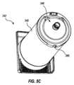
図5Bは、フィルタキャニスタ362の別の断面形状を示す。図5Bに示される形状362は、断面形状362がキーノッチ364を含むことを除いて、図5Aに示される形状360、361と同様である。このソケットの断面形状は、対応するキー溝365を有する。図5Cは、図5Bに示されるような断面形状362を有する第2の端部346を含むキャニスタアセンブリ342を示す。図5Dは、図5Bに示されるような断面形状362を有する第1の凹部328を有するソケット326を含む排煙システム300を示す。キャニスタアセンブリ342の第2の端部346のキーノッチ366は、挿入されるために、ソケット326の第1の凹部328のキー溝368と位置合わせされなければならない。キーノッチ366及び溝368は、キャニスタアセンブリ342がソケット326の中に適切に挿入されることを更に確実にすることができる。形状360及び362の他の実施形態も本明細書において企図される。例えば、キーノッチ364を備えた円形又は正方形の形状も用いられてよい。 FIG. 5B shows another cross-sectional shape for
キャニスタアセンブリ342がソケット326に挿入される前に、キャニスタアセンブリ342及びソケット326上の複数のキーノッチ366及び溝368が位置合わせされなければならないようにするため、他の実施形態は、断面形状362の周囲の様々な位置に、1つ超のキーノッチ366及び溝368を含んでもよい。また、キャニスタアセンブリ342のいくつかの実施形態は、図5A及び5Bに示され本明細書に記載される断面形状を有する本体348を含んでもよく、その結果、挿入されたときにその本体348の形状がソケット326に対応するようになっている。 Other embodiments modify the
いくつかの実施形態では、キーノッチ366は、キャニスタアセンブリ342の本体348の全長に沿って延在してもよく、キー溝368は、ソケット326の第1の凹部328の全長に沿って延在しなくてもよい。他の実施形態では、キーノッチ366は、キャニスタアセンブリ342の本体348の全長に沿って延在してもよく、更にキー溝368が、ソケット326の第1の凹部328の全長に沿って延在してもよい。本明細書に記載される実施形態のいずれかにおいて、キーノッチ366及び溝368は、キャニスタアセンブリ342が一旦ソケット326の中に挿入されると、キャニスタアセンブリ342がソケット326内で回転/捻回され得ないように構成されてよい。 In some embodiments, the
キャニスタアセンブリ342が正しい向きで挿入されることを確実にすることが重要である理由の1つは、結果として第1の電子コネクタ356と第2の電子コネクタ340とが互いに接触するようになることである。一実施形態において、第2の電子コネクタ340はEPROMコネクタであり得る。第2の電子コネクタ340は、図3Bに示されるように、ソケット326内に配設され得る。第1の電子メモリ356は、図4Bに示されるように、キャニスタアセンブリ342の第2の端部346に配設され得る。したがって、第1及び第2の電子コネクタ356、340は、キャニスタアセンブリ346及びソケット326の第1の凹部328が適切に位置合わせされていれば、キャニスタアセンブリ342がソケット326の中に完全に挿入されたときに第1の電子コネクタ356と第2の電子コネクタ340とが接するように配設され得る。 One reason it is important to ensure that the
図4Bの例示された実施形態では、第1の電子コネクタ356は、キャニスタアセンブリ342の第2の端部346の上縁部に配設されている。この位置は、図6Aに示すように、ソケット326内に配設された第2の電子コネクタ340の位置に対応する。他の実施形態は、キャニスタアセンブリ342の第2の端部346上及びソケット326内の様々な位置に配置された第1及び第2の電子コネクタ356、340を含んでもよい。キャニスタアセンブリ342がソケット326の中に挿入されるときに第1の電子コネクタ356と第2の電子コネクタ340とが接触する限り、いかなる位置も好適である。 In the illustrated embodiment of FIG. 4B, first
第1の電子コネクタ356と第2の電子コネクタ340とが互いに接触すると、電子メモリは、フィルタに関する情報をユーザ又は排煙システム342の他の構成要素に中継することができる。そのような情報としては、フィルタが使用された回数、そのフィルタが正しいフィルタであるかどうか、フィルタが依然として適切に機能しているかどうか、フィルタの寿命/濾過能力がどれだけ残っているか、などを挙げることができるが、これらに限定はされない。この接続により、定期的に交換することが必要なフィルタを安全に、確実に、かつ効率的に使用することが可能となる。電子メモリはまた、フィルタが適切に挿入されていることを通知し、排煙システム300を起動するために使用されてもよい。 When the first
図6A及び図6Bは、ソケット326の中に挿入されたキャニスタアセンブリ342の一実施形態を示す。図6Aは、ソケット326の中に部分的に挿入されたキャニスタアセンブリ342を示し、図6Bは、ソケット326の中に完全に挿入されたキャニスタアセンブリ342を示す。図6Aを参照すると、キャニスタアセンブリ342は、接続ニップル354がソケット326の第2の凹部332によって受容されるように、ソケット326の中に部分的に挿入されている。接続ニップル354を取り囲むシール358は、第2の凹部332の内側表面と接触して、キャニスタ出口352においてキャニスタアセンブリ342から出る濾過されたガスが排煙システム300の空気流経路308に進入するためのシールされた経路を作り出す。一実施形態において、シール358はOリングであり得る。他の実施形態はその他のシール358を含んでもよい。 FIGS. 6A and 6B show one embodiment of
シール358は、キャニスタアセンブリ342がソケット326の中に完全に挿入される前に、第2の凹部332の内壁と接触して、接続ニップル354と第2の凹部332との間にシールを作り出す。この部分的に挿入された構成では、プレート350は、排煙システム300の外側ハウジング320に接触せず、第1の電子コネクタ356と第2の電子コネクタ340とは互いに接触しない。
図6Bは、ソケット326の中に完全に挿入されたキャニスタアセンブリ342を示す。キャニスタアセンブリ342がソケット326の中に完全に挿入されると、シール358は、第2の凹部332内において接続ニップル354の周りにシールを維持する。加えて、キャニスタアセンブリ342がソケット326の中に完全に挿入されていると、キャニスタアセンブリ342が更に挿入され得ないように、プレート350は外側ハウジング320と接触し、かつ/又はキャニスタアセンブリ342の第2の端部346はソケット326の移行表面330に当接する。更に、キャニスタアセンブリ342が完全に挿入されると、第1の電子コネクタ356と第2の電子コネクタ340とは互いに接触する。次いで、この電子接続は上述のように機能し得る。 FIG. 6B shows
上述したように、電子接続は、吸引作用が真空管112を通じてフィルタ306の中に煙を引き込み始めるように、排煙システム300を起動するか又は排煙システムの起動を可能にし得る。本明細書に示される実施形態では、シールは、第1の電子コネクタ356と第2の電子コネク340とが接する前に、接続ニップル354とソケット326の第2の凹部332との間に気密な境界を形成する。換言すれば、シール358と第1の電子コネクタ356との間の長手方向距離D1は、ソケット326の第2の凹部332と第2の電子コネクタ340との間の長手方向距離D2より大きくてよい。長手方向距離D1及びD2は、図6Aに標識されている。 As described above, the electronic connection may activate the
あるいは、第1の電子コネクタ356は、フィルタキャニスタ342の第1の端部344に配設されてよく、第2の電子コネクタ340は、プレート350に又はその付近に配設されてよい。この構成では、シール458と第1の電子コネクタ356との間の長手方向距離は、第1の電子コネクタ356と第2の電子コネクタ340とが接する前に煙が空気流経路308の中へと進むためのシールが形成されるように、ソケット326の第2の凹部332と第2の電子コネクタ340との間の長手方向距離よりも依然として長くてもよい。第1の電子コネクタ356及び第2の電子コネクタ340は共に、上述の長手方向距離が依然として同じである限り、フィルタキャニスタ342上及びソケット326内の様々な位置に配設され得ることが理解されよう。 Alternatively, first
これらの構成により、空気流経路308と連通する閉鎖経路が確立されるまで、濾過されたガスがキャニスタ出口352から出ることができないように、排煙システム300はシールが形成されるまで起動されないことが確実となる。これらの構成は、キャニスタ出口352においてキャニスタアセンブリ342から出る濾過されたガスの漏洩を防止し得るものである。これらの構成はまた、フィルタキャニスタアセンブリ342がソケット326の中に完全かつ適切に挿入されるまで、排煙システム300がフィルタ306を通じた煙の引き込みを開始しないことを確実にし得る。 These configurations ensure that the
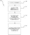
図7は、フィルタキャニスタを排煙システム370に接続するための方法を示す。第1の工程372では、フィルタキャニスタが供給される。フィルタキャニスタは、第1の端部と第2の端部との間に配設された本体と、第2の端部に配設された接続ニップルと、接続ニップルの周りに配設されたシールと、キーノッチと、ある断面形状と、第1の電子コネクタと、を含み得る。 FIG. 7 shows a method for connecting the filter canister to the smoke evacuation system 370 . In a first step 372, a filter canister is provided. The filter canister has a body disposed between a first end and a second end, a connecting nipple disposed at the second end, and a seal disposed about the connecting nipple. , a key notch, a cross-sectional shape, and a first electronic connector.
第2の工程374は、フィルタキャニスタの断面形状をソケットの断面形状と整列させることを含み得る。ソケットは、フィルタキャニスタの本体を受容するように構成された第1の凹部と、接続ニップルを受容するように構成された第2の凹部と、第1の凹部と第2の凹部とを接続する移行表面と、第2の電子コネクタと、を備え得る。 A second step 374 may include aligning the cross-sectional shape of the filter canister with the cross-sectional shape of the socket. A socket connects a first recess configured to receive the body of the filter canister, a second recess configured to receive the connecting nipple, and the first recess and the second recess. A transition surface and a second electronic connector may be provided.
第3の工程376は、フィルタキャニスタの接続ニップルとソケットの第2の凹部との間に気密な境界がシールによって形成されるまで、フィルタキャニスタをソケットの中に部分的に挿入することを含み得る。第4の工程378は、フィルタキャニスタの第2の端部がソケットの移行表面と接触するまで、また第1の電子コネクタと第2の電子コネクタとが互いに接触するまで、フィルタキャニスタをソケットの中に更に挿入することを含み得る。 A third step 376 may include partially inserting the filter canister into the socket until the seal forms an airtight boundary between the connecting nipple of the filter canister and the second recess of the socket. . A fourth step 378 moves the filter canister into the socket until the second end of the filter canister contacts the transition surface of the socket and until the first electronic connector and the second electronic connector contact each other. further inserting into the .
本明細書に記載されるフィルタキャニスタを挿入する方法は、電子接続が行われる前に、キャニスタの接続ニップルとソケットの第2の凹部との間に気密な境界を形成する。このように、排煙システムを起動するように構成され得る電子メモリは、接続ニップルから排煙システムの空気流経路につながるシールされた経路が確立されるまで接続されない。したがって、この方法は、濾過されたガスが排煙システムのソケットの中に完全に取り付けられる前にフィルタキャニスタから漏出することを防止し得る。 The method of inserting a filter canister described herein forms an airtight boundary between the canister's connection nipple and the socket's second recess before an electronic connection is made. As such, the electronic memory, which may be configured to activate the smoke evacuation system, is not connected until a sealed path is established from the connection nipple to the airflow path of the smoke evacuation system. Thus, this method may prevent filtered gas from leaking out of the filter canister before it is fully installed in the socket of the smoke evacuation system.
本発明は、その趣旨又は本質的な特性から逸脱することなく、他の特定の形態で具現化することができる。記載される実施形態は、あらゆる点で単なる例示にすぎず、限定的に解釈してはならない。したがって、本発明の範囲は、前述の説明によってではなく、添付の特許請求の範囲によって示される。特許請求の範囲に相当する意味及び範囲内に含まれる全ての変更は、それらの範囲内に包含されるものとする。 The invention may be embodied in other specific forms without departing from its spirit or essential characteristics. The described embodiments are merely illustrative in all respects and should not be construed as limiting. The scope of the invention is, therefore, indicated by the appended claims rather than by the foregoing description. All changes that come within the meaning and range of equivalency of the claims are to be embraced within their scope.
〔実施の態様〕
(1) 排煙システムのためのフィルタ接続部であって、
フィルタキャニスタであって、
本体と、
前記本体の端部に配設された接続ニップルと、
前記接続ニップルの周りに配設されたシールと、
第1の電子コネクタと、を備える、フィルタキャニスタと、
ソケットを有するハウジングであって、前記ソケットは、
前記キャニスタ本体を受容するように構成された第1の凹部と、
前記接続ニップルを受容するように構成された第2の凹部と、
第2の電子コネクタと、を備える、ハウジングと、を備え、
前記シールと前記第1の電子コネクタとの間の第1の長手方向距離は、前記第2の凹部と前記第2の電子コネクタとの間の第2の長手方向距離よりも長く、そのため、前記フィルタキャニスタが前記ソケットの中に挿入されるときに前記第1の電子コネクタと第2の電子コネクタとが接する前に、前記接続ニップルから前記第2の凹部へと延在するシールされた空気流経路が作られる、フィルタ接続部。
(2) 前記シールは、前記接続ニップルの外側表面と前記第2の凹部の内側表面との間に気密な境界を形成するOリングである、実施態様1に記載のフィルタ接続部。
(3) 前記シールは、前記フィルタキャニスタが前記ソケットの中に部分的に挿入されるときに前記気密な境界を形成する、実施態様2に記載のフィルタ接続部。
(4) 前記ソケットは、前記第1の凹部と第2の凹部とを接続する移行表面を更に備え、前記第1の電子コネクタは、前記フィルタキャニスタの第2の端部に配設され、前記第2の電子接続部は、前記ソケットの前記移行表面に配設されている、実施態様1に記載のフィルタ接続部。
(5) 前記第1の電子コネクタと前記第2の電子コネクタは、前記フィルタキャニスタが前記ソケットの中に完全に挿入されたときに互いに接触する、実施態様4に記載のフィルタ接続部。[Mode of implementation]
(1) A filter connection for a smoke extraction system comprising:
A filter canister,
the main body;
a connection nipple disposed at the end of the body;
a seal disposed around the connecting nipple;
a filter canister comprising a first electronic connector;
A housing having a socket, the socket comprising:
a first recess configured to receive the canister body;
a second recess configured to receive the connecting nipple;
a housing comprising a second electronic connector;
A first longitudinal distance between the seal and the first electronic connector is longer than a second longitudinal distance between the second recess and the second electronic connector, so that the A sealed airflow extending from the connection nipple into the second recess before the first and second electronic connectors meet when a filter canister is inserted into the socket. The filter connection where the path is made.
(2) The filter connection of claim 1, wherein said seal is an O-ring forming an airtight boundary between an outer surface of said connecting nipple and an inner surface of said second recess.
(3) The filter connection of claim 2, wherein the seal forms the airtight boundary when the filter canister is partially inserted into the socket.
(4) the socket further comprises a transition surface connecting the first recess and the second recess, the first electronic connector disposed at the second end of the filter canister; 2. The filter connection of claim 1, wherein a second electronic connection is disposed on the transition surface of the socket.
5. The filter connection of claim 4, wherein the first electronic connector and the second electronic connector contact each other when the filter canister is fully inserted into the socket.
(6) 前記ソケットは、前記ハウジング内に開口部を更に備え、前記第1の電子コネクタは、前記フィルタキャニスタの第1の端部に配設され、前記第2の電子コネクタは、前記フィルタキャニスタが前記ソケットの中に完全に挿入されたときに前記第1の電子コネクタと第2の電子コネクタとが接するように、前記ソケットの前記開口部に配設されている、実施態様1に記載のフィルタ接続部。
(7) 前記フィルタキャニスタの前記第2の端部は、1つのみの対称線を有する断面形状を備える、実施態様1に記載のフィルタ接続部。
(8) 前記第1の凹部は、1つのみの対称線を有する断面形状を備える、実施態様7に記載のフィルタ接続部。
(9) 前記フィルタキャニスタの前記第2の端部はキーノッチを備える、実施態様1に記載のフィルタ接続部。
(10) 前記第1の凹部は、前記キーノッチに対応するように構成されたキー溝を備える、実施態様9に記載のフィルタ接続部。(6) the socket further comprises an opening in the housing, the first electronic connector disposed at a first end of the filter canister, and the second electronic connector connecting to the filter canister; 2. A connector according to claim 1, disposed in the opening of the socket such that the first electronic connector and the second electronic connector abut when a connector is fully inserted into the socket. Filter connection.
Clause 7. The filter connection of clause 1, wherein the second end of the filter canister comprises a cross-sectional shape having only one line of symmetry.
(8) A filter connection according to claim 7, wherein the first recess comprises a cross-sectional shape having only one line of symmetry.
Clause 9. The filter connection of clause 1, wherein the second end of the filter canister comprises a key notch.
Aspect 10. A filter connection according to aspect 9, wherein the first recess comprises a keyway configured to correspond to the key notch.
(11) 前記フィルタキャニスタの前記第2の端部は、少なくとも部分的に円錐状の表面を備える、実施態様1に記載のフィルタ接続部。
(12) 前記ソケットは、前記第1の凹部と前記第2の凹部との間の部分的に円錐状の移行表面を備え、前記移行表面は、前記フィルタキャニスタの前記少なくとも部分的に円錐状の表面と嵌合するように構成されている、実施態様11に記載のフィルタ接続部。
(13) 前記接続ニップルは、円筒状の外側表面と、濾過されたガスが通過し得る内側経路と、を更に備える、実施態様1に記載のフィルタ接続部。
(14) 前記ソケットの前記第2の凹部は、前記排煙システムの空気流経路と連通し、前記濾過されたガスは、前記フィルタキャニスタが前記ソケットの中に完全に挿入されているとき、前記内側経路を通って、前記排煙システムの前記空気流経路の中へと進む、実施態様13に記載のフィルタ接続部。
(15) 排煙システムのためのフィルタキャニスタであって、
入口ポートを有する第1の端部と、
1つのみの対称線を備えた断面形状を有する第2の端部と、
前記第1の端部又は前記第2の端部のいずれかに配設された電子コネクタと、
前記第2の端部に配設された接続ニップルと、を備える、フィルタキャニスタ。Clause 11. The filter connection of clause 1, wherein the second end of the filter canister comprises an at least partially conical surface.
(12) said socket comprises a partially conical transition surface between said first recess and said second recess, said transition surface being aligned with said at least partially conical transition surface of said filter canister; 12. A filter connection according to claim 11, configured to mate with a surface.
13. The filter connection of claim 1, wherein the connection nipple further comprises a cylindrical outer surface and an inner passageway through which filtered gas can pass.
(14) said second recess of said socket is in communication with an air flow path of said smoke evacuation system, said filtered gas being allowed to flow into said outlet when said filter canister is fully inserted into said socket; 14. A filter connection according to clause 13, passing through an inner passage into the air flow path of the smoke evacuation system.
(15) A filter canister for a smoke extraction system comprising:
a first end having an inlet port;
a second end having a cross-sectional shape with only one line of symmetry;
an electronic connector disposed at either the first end or the second end;
a connection nipple disposed at the second end.
(16) キーノッチを更に備える、実施態様15に記載のフィルタキャニスタ。
(17) 前記接続ニップルの周りに配設されたシールを更に備える、実施態様15に記載のフィルタキャニスタ。
(18) 前記第1の端部と第2の端部との間に延在する本体を更に備える、実施態様15に記載のフィルタキャニスタ。
(19) 前記本体の断面形状は1つのみの対称線を有し、前記本体の前記断面形状は、前記第2の端部の前記断面形状と実質的に同様である、実施態様18に記載のフィルタキャニスタ。
(20) 排煙システム内にフィルタを接続するための方法であって、
フィルタキャニスタを供給することと、
前記排煙システムハウジング内にソケットを供給することと、
前記フィルタキャニスタが前記フィルタキャニスタと前記ソケットとの間に気密な境界を形成するように、前記フィルタキャニスタを前記ソケットの中に第1の距離だけ挿入することと、
前記フィルタキャニスタと前記ソケットとの間に電子接続が形成されるように、前記フィルタキャニスタを前記ソケットの中に第2の距離だけ挿入することと、を含み、
前記第2の距離は前記第1の距離より長い、方法。Aspect 16. The filter canister of aspect 15, further comprising a key notch.
17. The filter canister of claim 15, further comprising a seal disposed around said connecting nipple.
Clause 18. The filter canister of clause 15, further comprising a body extending between the first end and the second end.
Clause 19. Clause 18, wherein the cross-sectional shape of the body has only one line of symmetry, and wherein the cross-sectional shape of the body is substantially similar to the cross-sectional shape of the second end. of filter canisters.
(20) A method for connecting a filter within a smoke evacuation system comprising:
providing a filter canister;
providing a socket within the smoke evacuation system housing;
inserting the filter canister into the socket a first distance such that the filter canister forms an airtight boundary between the filter canister and the socket;
inserting the filter canister into the socket a second distance such that an electronic connection is formed between the filter canister and the socket;
The method, wherein the second distance is longer than the first distance.
(21) 前記方法は、
前記フィルタキャニスタを前記ソケットの中に挿入する前に、前記フィルタキャニスタの断面形状と前記ソケットの断面形状とが一致するように前記フィルタキャニスタを前記ソケットと位置合わせすることを更に含み、前記位置合わせによって前記フィルタキャニスタを前記ソケットの中に挿入することが可能となる、実施態様20に記載の方法。
(22) 前記方法は、
前記フィルタキャニスタを前記ソケットの中に挿入する前に、前記フィルタキャニスタのキーノッチが前記ソケットのキー溝と一致するように前記フィルタキャニスタを前記ソケットと位置合わせすることを更に含み、前記位置合わせによって前記フィルタキャニスタを前記ソケットの中に挿入することが可能となる、実施態様20に記載の方法。(21) The method comprises:
aligning the filter canister with the socket such that the cross-sectional shape of the filter canister matches the cross-sectional shape of the socket before inserting the filter canister into the socket; 21. The method of embodiment 20, wherein inserting the filter canister into the socket is enabled by .
(22) The method includes:
further comprising, prior to inserting the filter canister into the socket, aligning the filter canister with the socket such that a key notch of the filter canister is aligned with a keyway of the socket; 21. The method of embodiment 20, wherein a filter canister can be inserted into said socket.
Claims (17)
Translated fromJapaneseフィルタキャニスタであって、
本体と、
前記本体の端部に配設された接続ニップルと、
前記接続ニップルの周りに配設されたシールと、
第1の電子コネクタと、を備える、フィルタキャニスタと、
ソケットを有するハウジングであって、前記ソケットは、
前記本体を受容するように構成された第1の凹部と、
前記接続ニップルを受容するように構成された第2の凹部と、
第2の電子コネクタと、を備える、ハウジングと、を備え、
前記シールと前記第1の電子コネクタとの間の第1の長手方向距離は、前記第2の凹部と前記第2の電子コネクタとの間の第2の長手方向距離よりも長く、そのため、前記フィルタキャニスタが前記ソケットの中に挿入されるときに前記第1の電子コネクタと前記第2の電子コネクタとが接する前に、前記接続ニップルから前記第2の凹部へと延在するシールされた空気流経路が作られる、フィルタ接続部。A filter connection for a smoke extraction system, comprising:
A filter canister,
the main body;
a connection nipple disposed at the end of the body;
a seal disposed around the connecting nipple;
a filter canister comprising a first electronic connector;
A housing having a socket, the socket comprising:
a first recess configured to receivethe body ;
a second recess configured to receive the connecting nipple;
a housing comprising a second electronic connector;
A first longitudinal distance between the seal and the first electronic connector is longer than a second longitudinal distance between the second recess and the second electronic connector, so that the Sealed air extending from the connection nipple into the second recess before thefirst electronic connector and the second electronic connector meet when the filter canister is inserted into the socket. A filter connection where a flow path is created.
フィルタキャニスタを供給することと、
前記排煙システムのハウジング内にソケットを供給することと、
前記フィルタキャニスタが前記フィルタキャニスタと前記ソケットとの間に気密な境界を形成するように、前記フィルタキャニスタを前記ソケットの中に第1の距離だけ挿入することと、
前記フィルタキャニスタと前記ソケットとの間に電子接続が形成されるように、前記フィルタキャニスタを前記ソケットの中に第2の距離だけ挿入することと、を含み、
前記第2の距離は前記第1の距離より長い、方法。A method for connecting a filter within a smoke evacuation system comprising:
providing a filter canister;
providing a socket within the housingof the smoke evacuation system;
inserting the filter canister into the socket a first distance such that the filter canister forms an airtight boundary between the filter canister and the socket;
inserting the filter canister into the socket a second distance such that an electronic connection is formed between the filter canister and the socket;
The method, wherein the second distance is longer than the first distance.
前記フィルタキャニスタを前記ソケットの中に挿入する前に、前記フィルタキャニスタの断面形状と前記ソケットの断面形状とが一致するように前記フィルタキャニスタを前記ソケットと位置合わせすることを更に含み、前記位置合わせによって前記フィルタキャニスタを前記ソケットの中に挿入することが可能となる、請求項15に記載の方法。The method includes:
aligning the filter canister with the socket such that the cross-sectional shape of the filter canister matches the cross-sectional shape of the socket before inserting the filter canister into the socket; 16. The method of claim15 , wherein allowing the filter canister to be inserted into the socket.
前記フィルタキャニスタを前記ソケットの中に挿入する前に、前記フィルタキャニスタのキーノッチが前記ソケットのキー溝と一致するように前記フィルタキャニスタを前記ソケットと位置合わせすることを更に含み、前記位置合わせによって前記フィルタキャニスタを前記ソケットの中に挿入することが可能となる、請求項15に記載の方法。The method includes:
further comprising, prior to inserting the filter canister into the socket, aligning the filter canister with the socket such that a key notch of the filter canister is aligned with a keyway of the socket; 16. The method of claim15 , wherein a filter canister can be inserted into said socket.
Applications Claiming Priority (3)
| Application Number | Priority Date | Filing Date | Title |
|---|---|---|---|
| US15/826,325 | 2017-11-29 | ||
| US15/826,325US10631916B2 (en) | 2017-11-29 | 2017-11-29 | Filter connection for a smoke evacuation device |
| PCT/IB2018/059370WO2019106541A1 (en) | 2017-11-29 | 2018-11-27 | Filter connection for a smoke evacuation device |
Publications (2)
| Publication Number | Publication Date |
|---|---|
| JP2021504057A JP2021504057A (en) | 2021-02-15 |
| JP7279043B2true JP7279043B2 (en) | 2023-05-22 |
Family
ID=64902138
Family Applications (1)
| Application Number | Title | Priority Date | Filing Date |
|---|---|---|---|
| JP2020529383AActiveJP7279043B2 (en) | 2017-11-29 | 2018-11-27 | Filter connection for smoke evacuator |
Country Status (6)
| Country | Link |
|---|---|
| US (2) | US10631916B2 (en) |
| EP (1) | EP3717056B1 (en) |
| JP (1) | JP7279043B2 (en) |
| CN (1) | CN111867668B (en) |
| BR (1) | BR112020008582A2 (en) |
| WO (1) | WO2019106541A1 (en) |
Families Citing this family (135)
| Publication number | Priority date | Publication date | Assignee | Title |
|---|---|---|---|---|
| US11871901B2 (en) | 2012-05-20 | 2024-01-16 | Cilag Gmbh International | Method for situational awareness for surgical network or surgical network connected device capable of adjusting function based on a sensed situation or usage |
| US11504192B2 (en) | 2014-10-30 | 2022-11-22 | Cilag Gmbh International | Method of hub communication with surgical instrument systems |
| US11229436B2 (en) | 2017-10-30 | 2022-01-25 | Cilag Gmbh International | Surgical system comprising a surgical tool and a surgical hub |
| US11925373B2 (en) | 2017-10-30 | 2024-03-12 | Cilag Gmbh International | Surgical suturing instrument comprising a non-circular needle |
| US11026687B2 (en) | 2017-10-30 | 2021-06-08 | Cilag Gmbh International | Clip applier comprising clip advancing systems |
| US11291510B2 (en) | 2017-10-30 | 2022-04-05 | Cilag Gmbh International | Method of hub communication with surgical instrument systems |
| US11510741B2 (en) | 2017-10-30 | 2022-11-29 | Cilag Gmbh International | Method for producing a surgical instrument comprising a smart electrical system |
| US11564756B2 (en) | 2017-10-30 | 2023-01-31 | Cilag Gmbh International | Method of hub communication with surgical instrument systems |
| US11911045B2 (en) | 2017-10-30 | 2024-02-27 | Cllag GmbH International | Method for operating a powered articulating multi-clip applier |
| US11311342B2 (en) | 2017-10-30 | 2022-04-26 | Cilag Gmbh International | Method for communicating with surgical instrument systems |
| US11317919B2 (en) | 2017-10-30 | 2022-05-03 | Cilag Gmbh International | Clip applier comprising a clip crimping system |
| US11801098B2 (en) | 2017-10-30 | 2023-10-31 | Cilag Gmbh International | Method of hub communication with surgical instrument systems |
| US11234754B2 (en) | 2017-11-29 | 2022-02-01 | Megadyne Medical Products, Inc. | Smoke evacuation device |
| USD886976S1 (en) | 2017-11-29 | 2020-06-09 | Megadyne Medical Products, Inc. | Filter cartridge |
| US11725664B2 (en) | 2017-11-29 | 2023-08-15 | Megadyne Medical Products, Inc. | Noise and vibration management for smoke evacuation system |
| US10631916B2 (en)* | 2017-11-29 | 2020-04-28 | Megadyne Medical Products, Inc. | Filter connection for a smoke evacuation device |
| US11896322B2 (en) | 2017-12-28 | 2024-02-13 | Cilag Gmbh International | Sensing the patient position and contact utilizing the mono-polar return pad electrode to provide situational awareness to the hub |
| US11937769B2 (en) | 2017-12-28 | 2024-03-26 | Cilag Gmbh International | Method of hub communication, processing, storage and display |
| US11633237B2 (en) | 2017-12-28 | 2023-04-25 | Cilag Gmbh International | Usage and technique analysis of surgeon / staff performance against a baseline to optimize device utilization and performance for both current and future procedures |
| US10918310B2 (en) | 2018-01-03 | 2021-02-16 | Biosense Webster (Israel) Ltd. | Fast anatomical mapping (FAM) using volume filling |
| US20190201112A1 (en) | 2017-12-28 | 2019-07-04 | Ethicon Llc | Computer implemented interactive surgical systems |
| US11744604B2 (en) | 2017-12-28 | 2023-09-05 | Cilag Gmbh International | Surgical instrument with a hardware-only control circuit |
| US11389164B2 (en) | 2017-12-28 | 2022-07-19 | Cilag Gmbh International | Method of using reinforced flexible circuits with multiple sensors to optimize performance of radio frequency devices |
| US20190201090A1 (en) | 2017-12-28 | 2019-07-04 | Ethicon Llc | Capacitive coupled return path pad with separable array elements |
| US11559308B2 (en) | 2017-12-28 | 2023-01-24 | Cilag Gmbh International | Method for smart energy device infrastructure |
| US11026751B2 (en) | 2017-12-28 | 2021-06-08 | Cilag Gmbh International | Display of alignment of staple cartridge to prior linear staple line |
| US11304763B2 (en) | 2017-12-28 | 2022-04-19 | Cilag Gmbh International | Image capturing of the areas outside the abdomen to improve placement and control of a surgical device in use |
| US11013563B2 (en) | 2017-12-28 | 2021-05-25 | Ethicon Llc | Drive arrangements for robot-assisted surgical platforms |
| US11308075B2 (en) | 2017-12-28 | 2022-04-19 | Cilag Gmbh International | Surgical network, instrument, and cloud responses based on validation of received dataset and authentication of its source and integrity |
| US11273001B2 (en) | 2017-12-28 | 2022-03-15 | Cilag Gmbh International | Surgical hub and modular device response adjustment based on situational awareness |
| US11786245B2 (en) | 2017-12-28 | 2023-10-17 | Cilag Gmbh International | Surgical systems with prioritized data transmission capabilities |
| US20190201142A1 (en) | 2017-12-28 | 2019-07-04 | Ethicon Llc | Automatic tool adjustments for robot-assisted surgical platforms |
| US11069012B2 (en) | 2017-12-28 | 2021-07-20 | Cilag Gmbh International | Interactive surgical systems with condition handling of devices and data capabilities |
| US11179175B2 (en) | 2017-12-28 | 2021-11-23 | Cilag Gmbh International | Controlling an ultrasonic surgical instrument according to tissue location |
| US11696760B2 (en) | 2017-12-28 | 2023-07-11 | Cilag Gmbh International | Safety systems for smart powered surgical stapling |
| US10892899B2 (en) | 2017-12-28 | 2021-01-12 | Ethicon Llc | Self describing data packets generated at an issuing instrument |
| US11464535B2 (en) | 2017-12-28 | 2022-10-11 | Cilag Gmbh International | Detection of end effector emersion in liquid |
| US10943454B2 (en) | 2017-12-28 | 2021-03-09 | Ethicon Llc | Detection and escalation of security responses of surgical instruments to increasing severity threats |
| US11234756B2 (en) | 2017-12-28 | 2022-02-01 | Cilag Gmbh International | Powered surgical tool with predefined adjustable control algorithm for controlling end effector parameter |
| US11202570B2 (en) | 2017-12-28 | 2021-12-21 | Cilag Gmbh International | Communication hub and storage device for storing parameters and status of a surgical device to be shared with cloud based analytics systems |
| US11056244B2 (en) | 2017-12-28 | 2021-07-06 | Cilag Gmbh International | Automated data scaling, alignment, and organizing based on predefined parameters within surgical networks |
| US11076921B2 (en) | 2017-12-28 | 2021-08-03 | Cilag Gmbh International | Adaptive control program updates for surgical hubs |
| US10966791B2 (en) | 2017-12-28 | 2021-04-06 | Ethicon Llc | Cloud-based medical analytics for medical facility segmented individualization of instrument function |
| US11659023B2 (en) | 2017-12-28 | 2023-05-23 | Cilag Gmbh International | Method of hub communication |
| US10892995B2 (en) | 2017-12-28 | 2021-01-12 | Ethicon Llc | Surgical network determination of prioritization of communication, interaction, or processing based on system or device needs |
| US11571234B2 (en) | 2017-12-28 | 2023-02-07 | Cilag Gmbh International | Temperature control of ultrasonic end effector and control system therefor |
| US11291495B2 (en) | 2017-12-28 | 2022-04-05 | Cilag Gmbh International | Interruption of energy due to inadvertent capacitive coupling |
| US11786251B2 (en) | 2017-12-28 | 2023-10-17 | Cilag Gmbh International | Method for adaptive control schemes for surgical network control and interaction |
| US11304745B2 (en) | 2017-12-28 | 2022-04-19 | Cilag Gmbh International | Surgical evacuation sensing and display |
| US11051876B2 (en) | 2017-12-28 | 2021-07-06 | Cilag Gmbh International | Surgical evacuation flow paths |
| US11464559B2 (en) | 2017-12-28 | 2022-10-11 | Cilag Gmbh International | Estimating state of ultrasonic end effector and control system therefor |
| US20190206569A1 (en) | 2017-12-28 | 2019-07-04 | Ethicon Llc | Method of cloud based data analytics for use with the hub |
| US11903601B2 (en) | 2017-12-28 | 2024-02-20 | Cilag Gmbh International | Surgical instrument comprising a plurality of drive systems |
| US11529187B2 (en) | 2017-12-28 | 2022-12-20 | Cilag Gmbh International | Surgical evacuation sensor arrangements |
| US11602393B2 (en) | 2017-12-28 | 2023-03-14 | Cilag Gmbh International | Surgical evacuation sensing and generator control |
| US11284936B2 (en) | 2017-12-28 | 2022-03-29 | Cilag Gmbh International | Surgical instrument having a flexible electrode |
| US11832899B2 (en) | 2017-12-28 | 2023-12-05 | Cilag Gmbh International | Surgical systems with autonomously adjustable control programs |
| US11364075B2 (en) | 2017-12-28 | 2022-06-21 | Cilag Gmbh International | Radio frequency energy device for delivering combined electrical signals |
| US11540855B2 (en) | 2017-12-28 | 2023-01-03 | Cilag Gmbh International | Controlling activation of an ultrasonic surgical instrument according to the presence of tissue |
| US12396806B2 (en) | 2017-12-28 | 2025-08-26 | Cilag Gmbh International | Adjustment of a surgical device function based on situational awareness |
| US11304699B2 (en) | 2017-12-28 | 2022-04-19 | Cilag Gmbh International | Method for adaptive control schemes for surgical network control and interaction |
| US11832840B2 (en) | 2017-12-28 | 2023-12-05 | Cilag Gmbh International | Surgical instrument having a flexible circuit |
| US11666331B2 (en) | 2017-12-28 | 2023-06-06 | Cilag Gmbh International | Systems for detecting proximity of surgical end effector to cancerous tissue |
| US11324557B2 (en) | 2017-12-28 | 2022-05-10 | Cilag Gmbh International | Surgical instrument with a sensing array |
| US12376855B2 (en) | 2017-12-28 | 2025-08-05 | Cilag Gmbh International | Safety systems for smart powered surgical stapling |
| US12127729B2 (en) | 2017-12-28 | 2024-10-29 | Cilag Gmbh International | Method for smoke evacuation for surgical hub |
| WO2019133144A1 (en) | 2017-12-28 | 2019-07-04 | Ethicon Llc | Detection and escalation of security responses of surgical instruments to increasing severity threats |
| US11132462B2 (en) | 2017-12-28 | 2021-09-28 | Cilag Gmbh International | Data stripping method to interrogate patient records and create anonymized record |
| US12062442B2 (en) | 2017-12-28 | 2024-08-13 | Cilag Gmbh International | Method for operating surgical instrument systems |
| US11419630B2 (en) | 2017-12-28 | 2022-08-23 | Cilag Gmbh International | Surgical system distributed processing |
| US11266468B2 (en) | 2017-12-28 | 2022-03-08 | Cilag Gmbh International | Cooperative utilization of data derived from secondary sources by intelligent surgical hubs |
| US11376002B2 (en) | 2017-12-28 | 2022-07-05 | Cilag Gmbh International | Surgical instrument cartridge sensor assemblies |
| US12096916B2 (en) | 2017-12-28 | 2024-09-24 | Cilag Gmbh International | Method of sensing particulate from smoke evacuated from a patient, adjusting the pump speed based on the sensed information, and communicating the functional parameters of the system to the hub |
| US11424027B2 (en) | 2017-12-28 | 2022-08-23 | Cilag Gmbh International | Method for operating surgical instrument systems |
| US10987178B2 (en) | 2017-12-28 | 2021-04-27 | Ethicon Llc | Surgical hub control arrangements |
| US10944728B2 (en) | 2017-12-28 | 2021-03-09 | Ethicon Llc | Interactive surgical systems with encrypted communication capabilities |
| US11969216B2 (en) | 2017-12-28 | 2024-04-30 | Cilag Gmbh International | Surgical network recommendations from real time analysis of procedure variables against a baseline highlighting differences from the optimal solution |
| US11166772B2 (en) | 2017-12-28 | 2021-11-09 | Cilag Gmbh International | Surgical hub coordination of control and communication of operating room devices |
| US11998193B2 (en) | 2017-12-28 | 2024-06-04 | Cilag Gmbh International | Method for usage of the shroud as an aspect of sensing or controlling a powered surgical device, and a control algorithm to adjust its default operation |
| US11818052B2 (en) | 2017-12-28 | 2023-11-14 | Cilag Gmbh International | Surgical network determination of prioritization of communication, interaction, or processing based on system or device needs |
| US11559307B2 (en) | 2017-12-28 | 2023-01-24 | Cilag Gmbh International | Method of robotic hub communication, detection, and control |
| US11147607B2 (en) | 2017-12-28 | 2021-10-19 | Cilag Gmbh International | Bipolar combination device that automatically adjusts pressure based on energy modality |
| US10932872B2 (en) | 2017-12-28 | 2021-03-02 | Ethicon Llc | Cloud-based medical analytics for linking of local usage trends with the resource acquisition behaviors of larger data set |
| US11253315B2 (en) | 2017-12-28 | 2022-02-22 | Cilag Gmbh International | Increasing radio frequency to create pad-less monopolar loop |
| US11576677B2 (en) | 2017-12-28 | 2023-02-14 | Cilag Gmbh International | Method of hub communication, processing, display, and cloud analytics |
| US11096693B2 (en) | 2017-12-28 | 2021-08-24 | Cilag Gmbh International | Adjustment of staple height of at least one row of staples based on the sensed tissue thickness or force in closing |
| US11100631B2 (en) | 2017-12-28 | 2021-08-24 | Cilag Gmbh International | Use of laser light and red-green-blue coloration to determine properties of back scattered light |
| US11896443B2 (en) | 2017-12-28 | 2024-02-13 | Cilag Gmbh International | Control of a surgical system through a surgical barrier |
| US11423007B2 (en) | 2017-12-28 | 2022-08-23 | Cilag Gmbh International | Adjustment of device control programs based on stratified contextual data in addition to the data |
| US11589888B2 (en) | 2017-12-28 | 2023-02-28 | Cilag Gmbh International | Method for controlling smart energy devices |
| US20190201039A1 (en) | 2017-12-28 | 2019-07-04 | Ethicon Llc | Situational awareness of electrosurgical systems |
| US11678881B2 (en) | 2017-12-28 | 2023-06-20 | Cilag Gmbh International | Spatial awareness of surgical hubs in operating rooms |
| US11160605B2 (en) | 2017-12-28 | 2021-11-02 | Cilag Gmbh International | Surgical evacuation sensing and motor control |
| US11278281B2 (en) | 2017-12-28 | 2022-03-22 | Cilag Gmbh International | Interactive surgical system |
| US11612444B2 (en) | 2017-12-28 | 2023-03-28 | Cilag Gmbh International | Adjustment of a surgical device function based on situational awareness |
| US11317937B2 (en) | 2018-03-08 | 2022-05-03 | Cilag Gmbh International | Determining the state of an ultrasonic end effector |
| US10898622B2 (en)* | 2017-12-28 | 2021-01-26 | Ethicon Llc | Surgical evacuation system with a communication circuit for communication between a filter and a smoke evacuation device |
| US11446052B2 (en) | 2017-12-28 | 2022-09-20 | Cilag Gmbh International | Variation of radio frequency and ultrasonic power level in cooperation with varying clamp arm pressure to achieve predefined heat flux or power applied to tissue |
| US11257589B2 (en) | 2017-12-28 | 2022-02-22 | Cilag Gmbh International | Real-time analysis of comprehensive cost of all instrumentation used in surgery utilizing data fluidity to track instruments through stocking and in-house processes |
| US11304720B2 (en) | 2017-12-28 | 2022-04-19 | Cilag Gmbh International | Activation of energy devices |
| US11109866B2 (en) | 2017-12-28 | 2021-09-07 | Cilag Gmbh International | Method for circular stapler control algorithm adjustment based on situational awareness |
| US11969142B2 (en) | 2017-12-28 | 2024-04-30 | Cilag Gmbh International | Method of compressing tissue within a stapling device and simultaneously displaying the location of the tissue within the jaws |
| US11432885B2 (en) | 2017-12-28 | 2022-09-06 | Cilag Gmbh International | Sensing arrangements for robot-assisted surgical platforms |
| US11311306B2 (en) | 2017-12-28 | 2022-04-26 | Cilag Gmbh International | Surgical systems for detecting end effector tissue distribution irregularities |
| US11857152B2 (en) | 2017-12-28 | 2024-01-02 | Cilag Gmbh International | Surgical hub spatial awareness to determine devices in operating theater |
| US11419667B2 (en) | 2017-12-28 | 2022-08-23 | Cilag Gmbh International | Ultrasonic energy device which varies pressure applied by clamp arm to provide threshold control pressure at a cut progression location |
| US11410259B2 (en) | 2017-12-28 | 2022-08-09 | Cilag Gmbh International | Adaptive control program updates for surgical devices |
| US10758310B2 (en) | 2017-12-28 | 2020-09-01 | Ethicon Llc | Wireless pairing of a surgical device with another device within a sterile surgical field based on the usage and situational awareness of devices |
| US11864728B2 (en) | 2017-12-28 | 2024-01-09 | Cilag Gmbh International | Characterization of tissue irregularities through the use of mono-chromatic light refractivity |
| US11179208B2 (en) | 2017-12-28 | 2021-11-23 | Cilag Gmbh International | Cloud-based medical analytics for security and authentication trends and reactive measures |
| US11534196B2 (en) | 2018-03-08 | 2022-12-27 | Cilag Gmbh International | Using spectroscopy to determine device use state in combo instrument |
| US11986233B2 (en) | 2018-03-08 | 2024-05-21 | Cilag Gmbh International | Adjustment of complex impedance to compensate for lost power in an articulating ultrasonic device |
| US12303159B2 (en) | 2018-03-08 | 2025-05-20 | Cilag Gmbh International | Methods for estimating and controlling state of ultrasonic end effector |
| US11259830B2 (en) | 2018-03-08 | 2022-03-01 | Cilag Gmbh International | Methods for controlling temperature in ultrasonic device |
| US11589865B2 (en) | 2018-03-28 | 2023-02-28 | Cilag Gmbh International | Methods for controlling a powered surgical stapler that has separate rotary closure and firing systems |
| US11278280B2 (en) | 2018-03-28 | 2022-03-22 | Cilag Gmbh International | Surgical instrument comprising a jaw closure lockout |
| US11207067B2 (en) | 2018-03-28 | 2021-12-28 | Cilag Gmbh International | Surgical stapling device with separate rotary driven closure and firing systems and firing member that engages both jaws while firing |
| US11471156B2 (en) | 2018-03-28 | 2022-10-18 | Cilag Gmbh International | Surgical stapling devices with improved rotary driven closure systems |
| US10973520B2 (en) | 2018-03-28 | 2021-04-13 | Ethicon Llc | Surgical staple cartridge with firing member driven camming assembly that has an onboard tissue cutting feature |
| US11090047B2 (en) | 2018-03-28 | 2021-08-17 | Cilag Gmbh International | Surgical instrument comprising an adaptive control system |
| US11219453B2 (en) | 2018-03-28 | 2022-01-11 | Cilag Gmbh International | Surgical stapling devices with cartridge compatible closure and firing lockout arrangements |
| US11096688B2 (en) | 2018-03-28 | 2021-08-24 | Cilag Gmbh International | Rotary driven firing members with different anvil and channel engagement features |
| US11213294B2 (en) | 2018-03-28 | 2022-01-04 | Cilag Gmbh International | Surgical instrument comprising co-operating lockout features |
| GB2575050B (en) | 2018-06-26 | 2022-09-14 | Draeger Safety Uk Ltd | Connection apparatus for breathing apparatus |
| US11464511B2 (en) | 2019-02-19 | 2022-10-11 | Cilag Gmbh International | Surgical staple cartridges with movable authentication key arrangements |
| US11317915B2 (en) | 2019-02-19 | 2022-05-03 | Cilag Gmbh International | Universal cartridge based key feature that unlocks multiple lockout arrangements in different surgical staplers |
| US11369377B2 (en) | 2019-02-19 | 2022-06-28 | Cilag Gmbh International | Surgical stapling assembly with cartridge based retainer configured to unlock a firing lockout |
| US11357503B2 (en) | 2019-02-19 | 2022-06-14 | Cilag Gmbh International | Staple cartridge retainers with frangible retention features and methods of using same |
| US11331100B2 (en) | 2019-02-19 | 2022-05-17 | Cilag Gmbh International | Staple cartridge retainer system with authentication keys |
| USD964564S1 (en) | 2019-06-25 | 2022-09-20 | Cilag Gmbh International | Surgical staple cartridge retainer with a closure system authentication key |
| USD952144S1 (en) | 2019-06-25 | 2022-05-17 | Cilag Gmbh International | Surgical staple cartridge retainer with firing system authentication key |
| USD950728S1 (en) | 2019-06-25 | 2022-05-03 | Cilag Gmbh International | Surgical staple cartridge |
| US11877765B2 (en)* | 2020-06-26 | 2024-01-23 | Terumo Cardiovascular Systems Corporation | Endoscopic vessel harvesting devices with conditioning of insufflation gas |
| US20240009612A1 (en)* | 2022-07-06 | 2024-01-11 | Green Ladder Technologies, Llc | Medical filtration device and systems |
| KR102818106B1 (en)* | 2022-10-26 | 2025-06-10 | 주식회사 바이오프로테크 | surgical smoke inhaler |
Family Cites Families (120)
| Publication number | Priority date | Publication date | Assignee | Title |
|---|---|---|---|---|
| US1165288A (en) | 1913-05-07 | 1915-12-21 | James G Rimmer | Vibration-absorbing motor-stand. |
| US1789194A (en) | 1925-03-20 | 1931-01-13 | Paul O Rockwell | Process and apparatus for purifying air |
| US2577606A (en) | 1950-02-15 | 1951-12-04 | American Optical Corp | Filtering means for air supply devices |
| US3815752A (en) | 1972-03-02 | 1974-06-11 | Sporlan Valve Co | Refrigerant filter-drier |
| US4141677A (en) | 1977-08-15 | 1979-02-27 | Ingersoll-Rand Company | Scroll-type two stage positive fluid-displacement apparatus with intercooler |
| JPS5934485Y2 (en) | 1980-04-18 | 1984-09-25 | トキコ株式会社 | vehicle height adjustment device |
| US4619672A (en) | 1985-09-11 | 1986-10-28 | Xanar, Inc. | Filter for laser surgery smoke evacuation system |
| US4701193A (en)* | 1985-09-11 | 1987-10-20 | Xanar, Inc. | Smoke evacuator system for use in laser surgery |
| GB8622706D0 (en) | 1986-09-20 | 1986-10-29 | Domnick Hunter Filters Ltd | Filter assembly |
| US4826513A (en) | 1987-01-12 | 1989-05-02 | Stackhouse Wyman H | Laser smoke particulate/odor filter system |
| US4810269A (en) | 1988-04-27 | 1989-03-07 | Stackhouse Associates, Inc. | Point one micron filtering system |
| US4986839A (en) | 1988-11-10 | 1991-01-22 | Surgical Laser Products, Inc. | Self-contained air enhancement and laser plume evacuation system |
| IL89983A (en) | 1989-04-17 | 1992-08-18 | Ricor Ltd Cryogenic & Vacuum S | Electromagnetic vibrating system |
| US5318516A (en) | 1990-05-23 | 1994-06-07 | Ioan Cosmescu | Radio frequency sensor for automatic smoke evacuator system for a surgical laser and/or electrical apparatus and method therefor |
| US5108389A (en) | 1990-05-23 | 1992-04-28 | Ioan Cosmescu | Automatic smoke evacuator activator system for a surgical laser apparatus and method therefor |
| US5160334A (en) | 1991-04-30 | 1992-11-03 | Utah Medical Products, Inc. | Electrosurgical generator and suction apparatus |
| US5226939A (en)* | 1991-10-22 | 1993-07-13 | Stackhouse, Inc. | Surgical smoke evacuation system |
| EP0642376A4 (en) | 1991-11-01 | 1995-04-12 | Sorenson Laboratories, Inc. | Dual mode laser smoke evacuation system with sequential filter monitor and vacuum compensation. |
| AU4102493A (en) | 1992-03-16 | 1994-11-08 | Envirosurgical, Inc. | Surgery plume filter device and method of filtering |
| US5910291A (en) | 1992-03-16 | 1999-06-08 | Envirosurgical, Inc. | Surgery plume filter device and method of filtering |
| US5288469A (en) | 1992-03-16 | 1994-02-22 | Envirosurgical, Inc. | Surgery plume filter device |
| US5874052A (en) | 1992-05-15 | 1999-02-23 | Medtek Devices, Inc. | Antimicrobial filter for use in electrocautery or laser surgery |
| US5221192A (en) | 1992-07-16 | 1993-06-22 | Carrier Corporation | Elastomeric compressor stud mount |
| AU661907B2 (en) | 1992-10-08 | 1995-08-10 | Air Safe Exhaust Systems Pty. Limited | Gas filter |
| US5456248A (en)* | 1992-10-14 | 1995-10-10 | Stackhouse, Inc. | Surgical smoke evacuator |
| US5431650A (en) | 1992-12-11 | 1995-07-11 | Cosmescu; Ioan | Vortex hand piece shroud for automatic smoke evacuator system for a surgical laser apparatus and method therefor |
| US5336218A (en) | 1993-06-15 | 1994-08-09 | Laser Engineering, Inc. | Surgical smoke evacuator synchronizing system |
| US5342349A (en) | 1993-08-18 | 1994-08-30 | Sorenson Laboratories, Inc. | Apparatus and system for coordinating a surgical plume evacuator and power generator |
| US5423779A (en) | 1993-11-02 | 1995-06-13 | Yeh; Charles R. | High efficiency filtration particulate and smoke evacuator system |
| US5620441A (en) | 1994-06-15 | 1997-04-15 | Stackhouse, Inc. | Smoke evacuator remote on/off switch apparatus and method |
| US5674219A (en) | 1994-10-06 | 1997-10-07 | Donaldson Company, Inc. | Electrosurgical smoke evacuator |
| US5597385A (en) | 1994-11-21 | 1997-01-28 | Moerke Custom Products, Inc. | Filtered exhaust wand for removing laser smoke |
| US5690480A (en) | 1995-02-20 | 1997-11-25 | Hitachi, Ltd. | Scroll compressor with cooling holes in orbiting scroll |
| US6110259A (en) | 1997-11-21 | 2000-08-29 | Jlj International, Inc. | Smoke evacuation system |
| US5992413A (en) | 1997-12-24 | 1999-11-30 | Enternet Medical, Inc. | Heat and moisture exchanger and generator |
| US6511308B2 (en) | 1998-09-28 | 2003-01-28 | Air Squared, Inc. | Scroll vacuum pump with improved performance |
| US6129530A (en) | 1998-09-28 | 2000-10-10 | Air Squared, Inc. | Scroll compressor with a two-piece idler shaft and two piece scroll plates |
| US6439864B1 (en) | 1999-01-11 | 2002-08-27 | Air Squared, Inc. | Two stage scroll vacuum pump with improved pressure ratio and performance |
| US6544210B1 (en) | 1998-10-22 | 2003-04-08 | Gregory J. Trudel | Disposable laparoscopic smoke evacuation system |
| US6050792A (en) | 1999-01-11 | 2000-04-18 | Air-Squared, Inc. | Multi-stage scroll compressor |
| US6203590B1 (en) | 1999-03-25 | 2001-03-20 | Steris Corp | Surgical smoke evacuation system with replaceable filter cartridge module and accumulated filter usage display |
| DE60035213T2 (en) | 1999-11-05 | 2007-09-27 | Delaware Capital Formation, Inc., Wilmington | FLUE EXTRACTION DEVICE AND ARRANGEMENT |
| CA2299752A1 (en)* | 2000-02-28 | 2001-08-28 | Cst Coldswitch Technologies Inc. | Electro-surgical pencil with smoke evacuation |
| US6616722B1 (en) | 2000-05-09 | 2003-09-09 | Hmi Industries, Inc. | Room air cleaner |
| USD467654S1 (en) | 2000-10-13 | 2002-12-24 | Donaldson Company, Inc. | Air filter element having attached cover member |
| KR100396780B1 (en) | 2001-07-27 | 2003-09-02 | 엘지전자 주식회사 | Scroll compressor |
| JP4031222B2 (en) | 2001-09-21 | 2008-01-09 | アネスト岩田株式会社 | Scroll type fluid machine |
| JP4031223B2 (en) | 2001-09-27 | 2008-01-09 | アネスト岩田株式会社 | Scroll type fluid machine |
| US6524307B1 (en) | 2001-10-05 | 2003-02-25 | Medtek Devices, Inc. | Smoke evacuation apparatus |
| US6585791B1 (en) | 2002-01-29 | 2003-07-01 | Jon C. Garito | Smoke plume evacuation filtration system |
| US6758885B2 (en) | 2002-02-07 | 2004-07-06 | Visteon Global Technologies, Inc. | Screened carbon trap protection |
| US6592543B1 (en) | 2002-04-03 | 2003-07-15 | Surgin Inc. | Fluid flow regulator for a smoke evacuation system and method of using same |
| JP2004049704A (en) | 2002-07-23 | 2004-02-19 | Nipro Corp | Medical aspirator |
| US6902673B2 (en) | 2002-07-25 | 2005-06-07 | Stryker Instruments | Single port manifold |
| US20040223859A1 (en) | 2003-05-09 | 2004-11-11 | Ingersoll-Rand Company | Air compressor assembly |
| US20050000196A1 (en) | 2003-07-03 | 2005-01-06 | Schultz Leonard S. | Smoke evacuation system |
| USD513314S1 (en) | 2003-09-04 | 2005-12-27 | Donaldson Company, Inc. | Filter element |
| AU2004273890A1 (en) | 2003-09-15 | 2005-03-31 | Robert O. Dean | Operating room smoke evacuator with integrated vacuum motor and filter |
| US7497340B2 (en) | 2004-02-19 | 2009-03-03 | Stryker Corporation | Manifold and filter assembly with filter basket |
| US7014434B2 (en) | 2004-08-06 | 2006-03-21 | Anest Iwata Corporation | Scroll fluid machine |
| US20060099096A1 (en) | 2004-11-08 | 2006-05-11 | Shaffer Robert W | Scroll pump system |
| USD555803S1 (en) | 2004-12-03 | 2007-11-20 | Garito Jon C | Smoke evacuation system |
| US7465156B2 (en) | 2004-12-17 | 2008-12-16 | Lg Electronics Inc. | Apparatus for mounting compressor |
| US7294116B1 (en)* | 2005-01-03 | 2007-11-13 | Ellman Alan G | Surgical smoke plume evacuation system |
| USD521137S1 (en) | 2005-01-14 | 2006-05-16 | Royal Appliance Mfg. Co. | Filter |
| US20070066970A1 (en) | 2005-09-16 | 2007-03-22 | Leonard Ineson | Integrated electrosurgical cart and surgical smoke evacuator unit |
| US7615037B2 (en) | 2005-12-14 | 2009-11-10 | Stryker Corporation | Removable inlet manifold for a medical/surgical waste collection system, the manifold including a driver for actuating a valve integral with the waste collection system |
| KR100738708B1 (en) | 2005-12-29 | 2007-07-12 | 엘지전자 주식회사 | Anti-vibration device of scroll compressor |
| US8523544B2 (en) | 2010-04-16 | 2013-09-03 | Air Squared, Inc. | Three stage scroll vacuum pump |
| US7942655B2 (en) | 2006-02-14 | 2011-05-17 | Air Squared, Inc. | Advanced scroll compressor, vacuum pump, and expander |
| US7819957B2 (en) | 2006-06-14 | 2010-10-26 | Keith Roberts | Operating room filter systems |
| USD545955S1 (en) | 2006-07-26 | 2007-07-03 | Jesse Arias | High flow filter box |
| US7837866B2 (en) | 2006-10-12 | 2010-11-23 | Burrows Bruce D | Drainless reverse osmosis water purification system |
| DK2117621T3 (en) | 2007-03-01 | 2013-12-09 | Buffalo Filter Llc | Weights and relief valve for laparoscopic disposable smoke evacuation system |
| US20090022613A1 (en) | 2007-07-16 | 2009-01-22 | Dai Zhihuang | Asynchronous non-constant-pitch spiral scroll-type fluid displacement machine |
| JP4551430B2 (en) | 2007-09-07 | 2010-09-29 | 株式会社日立製作所 | Environmental radioactivity measurement management system and radioactivity intensity analysis method |
| US8142175B2 (en) | 2008-01-17 | 2012-03-27 | Bitzer Scroll Inc. | Mounting base and scroll compressor incorporating same |
| USD646368S1 (en) | 2008-06-06 | 2011-10-04 | Donaldson Company, Inc. | Filter cartridge |
| USD626204S1 (en) | 2009-03-31 | 2010-10-26 | Camfil Farr, Inc. | Canister filter |
| TWD137311S (en) | 2009-08-03 | 2010-10-11 | Smc股份有限公司 | Air filter |
| BR112012015601B1 (en)* | 2009-12-23 | 2020-07-14 | Fisher & Paykel Healthcare Limited | DISCHARGE ARM FOR SURGICAL SMOKE EVACUATION SYSTEM, SURGICAL SMOKE EVACUATION SYSTEM, APPLIANCE FOR WATER CONDITION DETERMINATION INSIDE A HUMIDIFICATION CHAMBER AND INSUFLATION SYSTEM |
| US8684705B2 (en) | 2010-02-26 | 2014-04-01 | Entegris, Inc. | Method and system for controlling operation of a pump based on filter information in a filter information tag |
| US8727744B2 (en) | 2010-02-26 | 2014-05-20 | Entegris, Inc. | Method and system for optimizing operation of a pump |
| USD648841S1 (en) | 2010-09-02 | 2011-11-15 | South Asia International (Hk) Limited | Air purifier |
| US8454059B2 (en)* | 2010-09-13 | 2013-06-04 | Pall Corporation | Connector assemblies, fluid systems including connector assemblies, and procedures for making fluid connections |
| WO2012044410A2 (en) | 2010-09-20 | 2012-04-05 | Surgiquest, Inc. | Multi-flow filtration system |
| DE102011013744A1 (en) | 2011-03-11 | 2012-09-13 | Gunnar Loske | Vacuum endoscopy system for endoscopic examination of gastro-intestinal track, has vaccum pump unit that is provided with receptacle to which over tube and endoscope are attached |
| JP5594196B2 (en) | 2011-03-14 | 2014-09-24 | 株式会社豊田自動織機 | Scroll compressor for vehicles |
| US9074598B2 (en) | 2011-08-09 | 2015-07-07 | Air Squared Manufacturing, Inc. | Scroll type device including compressor and expander functions in a single scroll plate pair |
| US9867914B2 (en)* | 2012-01-10 | 2018-01-16 | Buffalo Filter Llc | Fluid filtration device and system |
| US9415160B2 (en) | 2012-05-21 | 2016-08-16 | Buffalo Filter Llc | Fluid filtration device and system |
| US8608816B2 (en) | 2012-01-10 | 2013-12-17 | Buffalo Filter Llc | Fluid filtration device and system |
| CA2864683C (en) | 2012-02-14 | 2021-01-12 | Medtek Devices, Inc. | Medical boom filter system and method |
| US9549849B2 (en) | 2012-09-13 | 2017-01-24 | Alcon Research, Ltd. | Systems and methods for reinjection of processed vitreous humor |
| EP4257159A3 (en) | 2012-10-24 | 2023-10-25 | Stryker Corporation | Mobile cart of a waste collection system |
| CN105407948B (en)* | 2013-01-15 | 2023-02-28 | 费雪派克医疗保健有限公司 | Gas blowing device and method and gas generating cartridge thereof |
| US9435339B2 (en) | 2013-03-13 | 2016-09-06 | Agilent Technologies, Inc. | Vibration/noise management in a scroll compressor |
| US9259260B2 (en)* | 2013-03-14 | 2016-02-16 | Megadyne Medical Products, Inc. | Fluid evacuation device |
| CN103306973A (en) | 2013-05-29 | 2013-09-18 | 沈阳纪维应用技术有限公司 | Oilless vortex fluid mechanical device |
| WO2014210350A1 (en) | 2013-06-26 | 2014-12-31 | Buffalo Filter Llc | Method and system for vacuum suction |
| US9808754B2 (en) | 2014-02-14 | 2017-11-07 | Access Business Group International Llc | Air treatment system |
| GB2524755B (en) | 2014-03-31 | 2016-07-06 | Laprosurge Ltd | Variable flow smoke evacuation apparatus |
| US10390875B2 (en) | 2014-07-02 | 2019-08-27 | I.C. Medical, Inc. | System and apparatus for automatic activation using radio frequency sensor |
| KR101579438B1 (en) | 2014-07-02 | 2015-12-23 | 주식회사 오토스윙 | Information detectable structure of filter installed in pure air supplier of Respirator and method thereof |
| USD764649S1 (en) | 2014-09-30 | 2016-08-23 | Seoul Viosys Co., Ltd. | Air cleaner for vehicles |
| USD785678S1 (en) | 2014-12-24 | 2017-05-02 | Ngk Insulators, Ltd. | Catalyst carrier for exhaust gas purification |
| US9387295B1 (en) | 2015-01-30 | 2016-07-12 | SurgiQues, Inc. | Filter cartridge with internal gaseous seal for multimodal surgical gas delivery system having a smoke evacuation mode |
| US9387296B1 (en) | 2015-01-30 | 2016-07-12 | Surgiquest, Inc. | Filter cartridge with integrated gaseous seal for multimodal surgical gas delivery system |
| US10159809B2 (en) | 2015-01-30 | 2018-12-25 | Surgiquest, Inc. | Multipath filter assembly with integrated gaseous seal for multimodal surgical gas delivery system |
| US10777397B2 (en) | 2015-03-06 | 2020-09-15 | Micromass Uk Limited | Inlet instrumentation for ion analyser coupled to rapid evaporative ionisation mass spectrometry (“REIMS”) device |
| WO2017003712A1 (en) | 2015-06-30 | 2017-01-05 | Surgiquest, Inc. | Multipath filter assembly with integrated gaseous seal for multimodal surgical gas delivery system |
| JP6714700B2 (en)* | 2015-07-13 | 2020-06-24 | コンメッド コーポレイション | Surgical suction device using positive pressure gas |
| CA3005094C (en) | 2015-12-14 | 2021-05-25 | Buffalo Filter Llc | Method and apparatus for attachment and evacuation |
| EP4570278A3 (en) | 2015-12-24 | 2025-09-17 | Stryker Corporation | Waste collection unit |
| US9943355B2 (en) | 2016-03-30 | 2018-04-17 | Surgiquest, Inc. | Smoke evacuation system for invasive surgical procedures |
| USD890900S1 (en) | 2017-10-06 | 2020-07-21 | Kohler Co. | Air cleaner cover |
| USD886976S1 (en) | 2017-11-29 | 2020-06-09 | Megadyne Medical Products, Inc. | Filter cartridge |
| USD912762S1 (en) | 2017-11-29 | 2021-03-09 | Megadyne Medical Products, Inc. | Fluid trap |
| US10631916B2 (en) | 2017-11-29 | 2020-04-28 | Megadyne Medical Products, Inc. | Filter connection for a smoke evacuation device |
| US11234754B2 (en) | 2017-11-29 | 2022-02-01 | Megadyne Medical Products, Inc. | Smoke evacuation device |
- 2017
- 2017-11-29USUS15/826,325patent/US10631916B2/enactiveActive
- 2018
- 2018-11-27WOPCT/IB2018/059370patent/WO2019106541A1/ennot_activeCeased
- 2018-11-27EPEP18829469.8Apatent/EP3717056B1/enactiveActive
- 2018-11-27CNCN201880077232.3Apatent/CN111867668B/enactiveActive
- 2018-11-27JPJP2020529383Apatent/JP7279043B2/enactiveActive
- 2018-11-27BRBR112020008582-0Apatent/BR112020008582A2/ennot_activeApplication Discontinuation
- 2020
- 2020-03-20USUS16/825,998patent/US11185363B2/enactiveActive
Also Published As
| Publication number | Publication date |
|---|---|
| US11185363B2 (en) | 2021-11-30 |
| JP2021504057A (en) | 2021-02-15 |
| EP3717056B1 (en) | 2022-11-02 |
| EP3717056A1 (en) | 2020-10-07 |
| US20200214760A1 (en) | 2020-07-09 |
| WO2019106541A1 (en) | 2019-06-06 |
| CN111867668B (en) | 2022-11-18 |
| US10631916B2 (en) | 2020-04-28 |
| BR112020008582A2 (en) | 2020-10-20 |
| US20190159827A1 (en) | 2019-05-30 |
| CN111867668A (en) | 2020-10-30 |
Similar Documents
| Publication | Publication Date | Title |
|---|---|---|
| JP7279043B2 (en) | Filter connection for smoke evacuator | |
| CN111050829B (en) | Filter cartridge assembly | |
| US8114181B2 (en) | Reflux trap device | |
| CN107949336B (en) | tissue removal device | |
| CN217548097U (en) | Electrotomy biopsy needle and vacuum assisted breast biopsy device | |
| CN112842509A (en) | Tool bit for plasma scalpel and plasma scalpel | |
| CN218305099U (en) | Novel plasma hemostasis type nipple incision sword | |
| JP3244648B2 (en) | Endoscope cautery | |
| KR102785983B1 (en) | A Filter Embedded Type of a Surgical Device for Discharging a Gas | |
| EP3740260B1 (en) | Apparatus for flow | |
| JP2541760B2 (en) | Surgical suction tube | |
| US11607266B2 (en) | Electrosurgical device | |
| CN216090748U (en) | Nasal septum plasma scalpel and plasma surgical equipment | |
| CN102614013A (en) | Adjustable electrotome smoke suction device for medical operation | |
| CN218279787U (en) | Surgical smoke suction knife with multi-angle rotation | |
| CN221130028U (en) | Ripu cutter head and Li Pudao | |
| CN213249646U (en) | Operation electrode smoking structure and operation electrotome | |
| CN110711027B (en) | Smokable blunt electrosurgical dissection device | |
| KR102864600B1 (en) | Medical device for laparoscopic surgery | |
| CN217162270U (en) | Radio frequency ablation catheter and radio frequency ablation system | |
| CN221180596U (en) | Plasma surgical electrode, knife head structure and inner knife tube | |
| CN209269865U (en) | A kind of electric knife-pen | |
| CN120241141A (en) | Biopsy needles and biopsy sampling devices |
Legal Events
| Date | Code | Title | Description |
|---|---|---|---|
| A621 | Written request for application examination | Free format text:JAPANESE INTERMEDIATE CODE: A621 Effective date:20211110 | |
| A977 | Report on retrieval | Free format text:JAPANESE INTERMEDIATE CODE: A971007 Effective date:20221122 | |
| A131 | Notification of reasons for refusal | Free format text:JAPANESE INTERMEDIATE CODE: A131 Effective date:20221129 | |
| A601 | Written request for extension of time | Free format text:JAPANESE INTERMEDIATE CODE: A601 Effective date:20230228 | |
| A521 | Request for written amendment filed | Free format text:JAPANESE INTERMEDIATE CODE: A523 Effective date:20230310 | |
| TRDD | Decision of grant or rejection written | ||
| A01 | Written decision to grant a patent or to grant a registration (utility model) | Free format text:JAPANESE INTERMEDIATE CODE: A01 Effective date:20230425 | |
| A61 | First payment of annual fees (during grant procedure) | Free format text:JAPANESE INTERMEDIATE CODE: A61 Effective date:20230510 | |
| R150 | Certificate of patent or registration of utility model | Ref document number:7279043 Country of ref document:JP Free format text:JAPANESE INTERMEDIATE CODE: R150 |