JP7278864B2 - Nerve Stimulation Measuring Device, Nerve Stimulation Measuring Method and Nerve Stimulation Measuring Program - Google Patents
Nerve Stimulation Measuring Device, Nerve Stimulation Measuring Method and Nerve Stimulation Measuring ProgramDownload PDFInfo
- Publication number
- JP7278864B2 JP7278864B2JP2019091281AJP2019091281AJP7278864B2JP 7278864 B2JP7278864 B2JP 7278864B2JP 2019091281 AJP2019091281 AJP 2019091281AJP 2019091281 AJP2019091281 AJP 2019091281AJP 7278864 B2JP7278864 B2JP 7278864B2
- Authority
- JP
- Japan
- Prior art keywords
- stimulation
- current
- sessions
- predetermined
- control unit
- Prior art date
- Legal status (The legal status is an assumption and is not a legal conclusion. Google has not performed a legal analysis and makes no representation as to the accuracy of the status listed.)
- Active
Links
Images


Classifications
- A—HUMAN NECESSITIES
- A61—MEDICAL OR VETERINARY SCIENCE; HYGIENE
- A61N—ELECTROTHERAPY; MAGNETOTHERAPY; RADIATION THERAPY; ULTRASOUND THERAPY
- A61N1/00—Electrotherapy; Circuits therefor
- A61N1/18—Applying electric currents by contact electrodes
- A61N1/32—Applying electric currents by contact electrodes alternating or intermittent currents
- A61N1/36—Applying electric currents by contact electrodes alternating or intermittent currents for stimulation
- A61N1/36014—External stimulators, e.g. with patch electrodes
- A61N1/3603—Control systems
- A61N1/36031—Control systems using physiological parameters for adjustment
- A—HUMAN NECESSITIES
- A61—MEDICAL OR VETERINARY SCIENCE; HYGIENE
- A61N—ELECTROTHERAPY; MAGNETOTHERAPY; RADIATION THERAPY; ULTRASOUND THERAPY
- A61N1/00—Electrotherapy; Circuits therefor
- A61N1/02—Details
- A61N1/04—Electrodes
- A61N1/0404—Electrodes for external use
- A61N1/0408—Use-related aspects
- A61N1/0456—Specially adapted for transcutaneous electrical nerve stimulation [TENS]
- A—HUMAN NECESSITIES
- A61—MEDICAL OR VETERINARY SCIENCE; HYGIENE
- A61B—DIAGNOSIS; SURGERY; IDENTIFICATION
- A61B5/00—Measuring for diagnostic purposes; Identification of persons
- A61B5/24—Detecting, measuring or recording bioelectric or biomagnetic signals of the body or parts thereof
- A—HUMAN NECESSITIES
- A61—MEDICAL OR VETERINARY SCIENCE; HYGIENE
- A61B—DIAGNOSIS; SURGERY; IDENTIFICATION
- A61B5/00—Measuring for diagnostic purposes; Identification of persons
- A61B5/48—Other medical applications
- A61B5/4824—Touch or pain perception evaluation
Landscapes
- Health & Medical Sciences (AREA)
- Life Sciences & Earth Sciences (AREA)
- Animal Behavior & Ethology (AREA)
- Nuclear Medicine, Radiotherapy & Molecular Imaging (AREA)
- Radiology & Medical Imaging (AREA)
- Biomedical Technology (AREA)
- Engineering & Computer Science (AREA)
- General Health & Medical Sciences (AREA)
- Public Health (AREA)
- Veterinary Medicine (AREA)
- Biophysics (AREA)
- Physiology (AREA)
- Heart & Thoracic Surgery (AREA)
- Electrotherapy Devices (AREA)
- Measurement And Recording Of Electrical Phenomena And Electrical Characteristics Of The Living Body (AREA)
Description
Translated fromJapanese本発明は、神経刺激測定装置、神経刺激測定方法および神経刺激測定プログラムに関する。 The present invention relates to a nerve stimulation measurement device, a nerve stimulation measurement method, and a nerve stimulation measurement program.
被検者に貼り付けた電極に、手動で設定した電流値の電流を流して、被検者に電気刺激を与え、被検者が電気刺激を感じる電流値を測定する、痛覚神経刺激装置がある(たとえば特許文献1)。 A pain sensory nerve stimulator that applies a manually set current value to electrodes attached to a subject to provide electrical stimulation to the subject and measures the current value at which the subject feels the electrical stimulation. There is (for example, patent document 1).
しかし、従来の痛覚神経刺激装置では、電気刺激を与えるための電流を、検査者が手動で変化させ、被検者が電気刺激を感じる最小の電流値を探っていかなければならないため、検査者の手間が多くなる。また、電気刺激を与えるタイミングが検査者によって異なるため、測定結果が検査者に依存される。したがって、従来の痛覚神経刺激装置では、測定が煩雑であるばかりでなく、再現性のある測定結果を得にくい。 However, with the conventional pain sensory nerve stimulator, the examiner has to manually change the electric current for giving the electrical stimulation and search for the minimum current value at which the subject feels the electric stimulation. more time and effort. In addition, since the timing of applying electrical stimulation differs depending on the examiner, the measurement result depends on the examiner. Therefore, with the conventional pain sensory nerve stimulator, not only is the measurement complicated, but it is also difficult to obtain reproducible measurement results.
本発明は、上記のような従来の痛覚神経刺激装置の不具合を解消するために成されたものであり、簡素な構成で再現性のある測定結果を得ることができる、神経刺激測定装置、神経刺激測定方法および神経刺激測定プログラムの提供を目的とする。 DISCLOSURE OF THE INVENTION The present invention has been made to solve the problems of the conventional pain sensory nerve stimulator as described above. An object of the present invention is to provide a stimulation measurement method and a nerve stimulation measurement program.
上記目的を達成するための本発明の神経刺激測定装置は、電気刺激を与える電極部が装着された被検者が電気刺激を感じた場合に応答する応答部と、電極部に段階的に増加または減少する刺激電流を供給し、段階ごとの応答の状況から被検者が電気刺激を感じる刺激電流である感覚閾値を求める制御部と、を有する。 In order to achieve the above object, the nerve stimulation measurement apparatus of the present invention includes a response section that responds when a subject wearing an electrode section that provides electrical stimulation senses the electrical stimulation, and a stepwise increase in the number of electrode sections. or a control unit that supplies a decreasing stimulation current and obtains a sensory threshold, which is the stimulation current at which the subject feels electrical stimulation from the state of response in each stage.
上記目的を達成するための本発明の神経刺激測定方法は、応答部が、電気刺激を与える電極部が装着された被検者が電気刺激を感じた場合に応答する段階と、制御部が、電極部に段階的に増加または減少する刺激電流を供給し、段階ごとの応答の状況から被検者が電気刺激を感じる刺激電流である感覚閾値を求める段階と、を含む。 The method for measuring nerve stimulation of the present invention for achieving the above object includes a step in which a response unit responds when a subject wearing an electrode unit that provides electrical stimulation responds when the subject feels electrical stimulation; supplying a stepwise increasing or decreasing stimulating current to the electrode unit, and obtaining a sensory threshold, which is the stimulating current at which the subject feels electrical stimulation, from the state of response in each step.
上記目的を達成するための本発明の神経刺激測定プログラムは、コンピュータに、応答部が、電気刺激を与える電極部が装着された被検者が電気刺激を感じた場合に応答する段階と、制御部が、電極部に段階的に増加または減少する刺激電流を供給し、段階ごとの応答の状況から被検者が電気刺激を感じる刺激電流である感覚閾値を求める段階と、を実行させる。 The nerve stimulation measurement program of the present invention for achieving the above object is provided by a computer, wherein a response unit responds when a subject wearing an electrode unit that provides electrical stimulation responds to electrical stimulation, and a control supply a stepwise increasing or decreasing stimulation current to the electrode portion, and obtain a sensory threshold, which is the stimulation current at which the subject feels the electrical stimulation, from the state of the response in each step.
本発明の神経刺激測定装置、神経刺激測定方法および神経刺激測定プログラムによれば、簡素な構成で再現性のある測定結果を得ることができる。 According to the nerve stimulation measurement device, nerve stimulation measurement method, and nerve stimulation measurement program of the present invention, reproducible measurement results can be obtained with a simple configuration.
以下に、本発明の神経刺激測定装置、神経刺激測定方法および神経刺激測定プログラムの実施形態を説明する。
<神経刺激測定装置の構成>
図1は、本実施形態の神経刺激測定装置の測定時における外観図である。神経刺激測定装置100は、応答部120および本体部150を有する。なお、本体部150は、測定時に使用する電極部110と着脱可能に構成される。EMBODIMENT OF THE INVENTION Below, embodiment of the nerve stimulation measuring device of this invention, the nerve stimulation measuring method, and the nerve stimulation measuring program is described.
<Configuration of Nerve Stimulation Measurement Device>
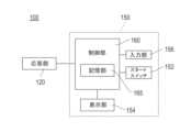
FIG. 1 is an external view of the nerve stimulation measurement device of this embodiment during measurement. Nerve
測定時に本体部150に接続される電極部110は、被検者の手の甲、足の甲など、電気刺激を感じやすい部分に装着される。電極部110は、コード115を介して本体部150に接続される。電極部110は、本体部150から供給される刺激電流によって、被検者に電気刺激を与える。 The
応答部120は、被検者が電気刺激を感じた場合に応答するために用いられる。応答部120は、コード125を介して本体部150に接続される。応答部120は応答ボタン122を備える。応答ボタン122は被検者が電気刺激を感じた場合に被検者によって押される。応答ボタン122が押された場合、本体部150が、刺激電流による被検者の応答を確認する。 The
本体部150は、スタートスイッチ152、表示部154、および入力部156を有する。スタートスイッチ152は、神経刺激測定装置100による測定を開始する場合に押されるスイッチである。スタートスイッチ152が押されることによって電極部110への刺激電流の供給から感覚閾値(被検者が電気刺激を感じる刺激電流:詳細は後述する)を求めるまでの一連の処理が自動的に行われる。なお、本実施形態では、スタートスイッチ152を本体部150の一部に設けているが、後述する表示部154内に表示させ、表示されているスタートスイッチ152を押すようにしても良い。 The
表示部154は、本体部150が求めた上記の感覚閾値、または測定不能である旨を表示する。表示内容の詳細は後述する。本実施形態では、表示部154は、一般的に用いられているLCDディスプレイ、または有機ELディスプレイを用いる。 The
入力部156は、本体部150内に設けられている記憶部に、たとえば、刺激電流の初期電流値、段階的に増加する刺激電流の既定の上昇間隔、段階的に減少する刺激電流の既定の下降間隔、応答待ち時間、既定のセッション数、既定の有効セッション数、および既定の有効電流範囲など、測定に必要な諸量を入力するために用いられる。なお、既定の有効セッション数とは、感覚閾値を求める際に必要となるセッションの数である。入力部156を設けると、測定に必要な諸量を操作者が自由に設定することができる。なお、本実施形態では、入力部156を本体部150の一部に設けているが、外部のコンピュータと接続可能な入力ポートを入力部156としても良い。この場合、測定に必要な諸量の入力は、外部のコンピュータから入力ポートを介して行われる。なお、これら測定に必要な諸量の詳細は後述する。 The
図2は、本実施形態の神経刺激測定装置の制御系のブロック図である。神経刺激測定装置100は、応答部120、および本体部150を有し、本体部150は、スタートスイッチ152、表示部154、入力部156、および制御部160を有する。制御部160は記憶部165を有する。 FIG. 2 is a block diagram of the control system of the nerve stimulation measurement device of this embodiment. Nerve
応答部120、本体部150、スタートスイッチ152、表示部154、および入力部156の構成は、上記の通りである。 The configurations of
制御部160は、電極部110に段階的に増加または減少する刺激電流を供給し段階ごとの応答部120による応答の状況から、被検者が電気刺激を感じる刺激電流である感覚閾値を求める。また、制御部160は、電極部110に段階的に増加する刺激電流を供給する場合には、記憶部165に記憶されている既定の上昇間隔にしたがって段階的に刺激電流を増加させ、電極部110に段階的に減少する刺激電流を供給する場合には、記憶部165に記憶されている既定の下降間隔にしたがって段階的に刺激電流を減少させる。制御部160の詳しい動作は、図4以降の図面に基づいて後述する。 The
記憶部165は、入力部156から入力される、たとえば、刺激電流の初期電流値、段階的に増加する刺激電流の上昇間隔、段階的に減少する刺激電流の下降間隔、応答待ち時間、既定のセッション数、既定の有効セッション数、および既定の有効電流範囲など、測定に必要な諸量を記憶する。また、記憶部165は、制御部160が求めた、セッション処理ごとの最小電流値および感覚閾値を記憶する。 The
図3は本実施形態の神経刺激測定装置の制御部の構成図である。制御部160は、神経刺激測定のための一連の処理を行うCPU162、CPU162による一連の処理の結果を一時的に記憶するRAM164、測定に必要な諸量を記憶する記憶部165、CPU162が神経刺激測定のために実行する、神経刺激測定プログラムを記憶するROM166、外部のコンピュータとの間で通信を行う外部I/F(外部インターフェース)168を有する。図3の構成を有する制御部160は、コンピュータとして機能する。
<神経刺激測定装置の動作>
図4から図6は、本実施形態の神経刺激測定装置の動作フローチャートである。これらの動作フローチャートを用いて神経刺激測定装置100の動作を詳細に説明する。なお、図4から図6の動作フローチャートは、本実施形態の神経刺激測定方法および神経刺激測定プログラムの手順を示すものでもある。FIG. 3 is a configuration diagram of the control unit of the nerve stimulation measurement apparatus of this embodiment. The
<Operation of Nerve Stimulation Measurement Device>
4 to 6 are operation flowcharts of the nerve stimulation measurement apparatus of this embodiment. The operation of the nerve
図4~図6の動作フローチャートは、スタートスイッチ152(図1および図2参照)が押されることにより、処理が開始される。 The operation flowcharts of FIGS. 4 to 6 start when the start switch 152 (see FIGS. 1 and 2) is pressed.
スタートスイッチ152が押されて処理が開始されると、制御部160は、記憶部165から初期電流値を読み出す(S100)。 When the
制御部160は、これから行う処理が初回のセッション処理であるか否かを判断する(S110)。初回のセッション処理であれば(S110:YES)、制御部160は、入力した初期電流値を初回の刺激電流値、すなわち初期刺激電流値として設定する(S120)。本実施形態では、初期刺激電流値を0.5mAとしている。しかし、初期刺激電流値の設定はこの電流値に限られない。制御部160は、次に初回のセッション処理を行う(S140)。 The
セッション処理は、図5の動作フローチャートの処理にしたがって実行される。制御部160は、図4の動作フローチャートのS120のステップで設定された刺激電流値を設定する(S200)。初回のセッション処理の場合、制御部160は、刺激電流値として初期刺激電流値を設定することになる。刺激電流値の設定が終了したら、次に、制御部160は刺激処理を行う(S210)。 Session processing is executed according to the processing of the operation flowchart of FIG. The
刺激処理(S210)は、図6の動作フローチャートの処理にしたがって実行される。制御部160は、刺激処理が開始されると、一定の時間(任意の時間たとえば2sec)待って(S300)、電極部110(図1および図2参照)に刺激電流を供給する(S310)。初回のセッション処理の場合、制御部160は、初期刺激電流値の刺激電流を電極部110に供給することになる。刺激電流は電極部110から被検者に供給される。被検者は、電気刺激を感じたら応答部120の応答ボタン122を押して応答する。 The stimulation process (S210) is executed according to the process of the operation flowchart of FIG. When the stimulation process is started, the
制御部160は、既定の時間内に応答があるか否かを判断する(S320)。本実施形態では、既定の時間、すなわち応答待ち時間を2secとしている。しかし、応答待ち時間はこの時間に限られない。 The
既定の時間内に応答があれば(S320:YES)、制御部160は応答ありと判定する(S330)。一方、既定の時間内に応答がなければ(S320:NO)、制御部160は刺激電流の供給を既定回数繰り返したか否かを判断する(S340)。S340のステップの処理を行うのは、1回の応答の確認だけで、応答なしと判断してしまうのは、測定の信頼性を確保する上では好ましくないからである。 If there is a response within the predetermined time (S320: YES), the
制御部160は刺激電流の供給を既定回数繰り返していなければ(S340:NO)、被検者からの応答があるか、刺激電流の供給を既定回数繰り返すまで、S310およびS320のステップの処理を行う。刺激電流の供給を既定回数繰り返したら(S340:YES)、制御部160は、応答なしと判定する(S350)。 If the
図6の動作フローチャートの刺激処理が終了し、応答あり、応答なしのいずれかの判定がされたら、図5の動作フローチャートのS220のステップに進む。 When the stimulus processing in the operation flowchart of FIG. 6 is completed and it is determined whether there is a response or there is no response, the process proceeds to step S220 in the operation flowchart of FIG.
次に、制御部160は、図6の動作フローチャートの刺激処理の結果から、被検者の応答があるか否かを判断する(S220)。被検者の応答があれば(S220:YES)、制御部160は、記憶部165に記憶されている、段階的に減少する刺激電流の下降間隔を参照して、次回の刺激電流値を設定する(S230)。本実施形態では、刺激電流の下降間隔を0.05mAとしている。しかし、刺激電流の下降間隔はこの電流値に限られない。この場合、初期刺激電流値が0.5mA、刺激電流の下降間隔が0.05mAであるので、次回の刺激電流は0.45mAに設定される。 Next, the
制御部160は、設定した次回の刺激電流値で、図6の動作フローチャートの刺激処理を行う(S240)。この場合、制御部160は、0.45mAの刺激電流を電極部110に供給して、被検者の応答の有無を確認することになる。 The
図6の動作フローチャートの刺激処理が終了し、応答あり、応答なしのいずれかの判定がされたら、図5の動作フローチャートのS250のステップに進む。 When the stimulus processing in the operation flowchart of FIG. 6 is completed and it is determined that there is a response or no response, the process proceeds to step S250 in the operation flowchart of FIG.
次に、制御部160は、図6の動作フローチャートの刺激処理の結果から、被検者の応答があるか否かを判断する(S250)。被検者の応答があれば(S250:YES)、制御部160は、記憶部165に記憶されている、段階的に減少する刺激電流の下降間隔を参照して、次回の刺激電流値を設定する(S230)。この場合、前回の刺激電流値が0.45mA、刺激電流の下降間隔が0.05mAであるので、次回の刺激電流は0.45mAに設定される。S230およびS240のステップの処理は、図6の動作フローチャートの刺激処理の結果において、被検者の応答がなくなるまで繰り返される。 Next, the
制御部160がS230およびS240のステップの処理を繰り返し行い、被検者の応答がなければ(S250:NO)、制御部160は、被検者の応答がなくなった直前の最小の刺激電流である最小電流値を記憶部165に記憶させる(S260)。 The
S220のステップの処理に戻って、被検者の応答がなければ(S220:NO)、制御部160は、記憶部165に記憶されている、段階的に増加する刺激電流の上昇間隔を参照して、次回の刺激電流値を設定する(S270)。本実施形態では、刺激電流の上昇間隔を0.1mAとしている。しかし、刺激電流の上昇間隔はこの電流値に限られない。この場合、初期刺激電流値が0.5mA、刺激電流の上昇間隔が0.1mAであるので、次回の刺激電流は0.6mAに設定される。 Returning to the process of step S220, if there is no response from the subject (S220: NO),
制御部160は、設定した次回の刺激電流値で、図6の動作フローチャートの刺激処理を行う(S210)。この場合、制御部160は、0.6mAの刺激電流を電極部110に供給して、被検者の応答の有無を確認する。図6の動作フローチャートの刺激処理を行うS210とS240のステップ処理は、S210のステップの処理においては被検者の応答があるまで、S240のステップの処理においては被検者の応答がなくなるまで、それぞれ繰り返される。 The
以上の処理によって図4の動作フローチャートのS140のステップのセッション処理、つまり、電極部110に刺激電流の供給を応答が確認できなくなるまで繰り返し行い応答が確認できる最小の刺激電流である最小電流値を求める1セッションのセッション処理が終了する。 Through the above processing, the session processing of step S140 in the operation flowchart of FIG. Session processing for the desired one session ends.
次に、制御部160は、記憶部165に記憶されている既定の有効電流範囲と既定の有効セッション数とを参照するとともに、以上のセッション処理において記憶した最小電流値を参照し、有効電流範囲内に有効セッション数以上の最小電流値があるか否かを判断する(S150)。ここで、有効電流範囲とは、各セッションで求めた最小電流値が相互に関連する範囲であり、有効セッション数とは、有効電流範囲内の最小電流値の数である。たとえば、有効電流範囲が0.1mA、有効セッション数が3であったとすると、S160のステップでは、有効電流範囲の0.1mA以内に3セッション以上の最小電流値があるか否かを判断する。 Next, the
有効電流範囲内に有効セッション数以上の最小電流値がなければ(S150:NO)、制御部160は、記憶部165に記憶されている既定のセッション数を参照して、既定回数のセッション処理が終了したか否かを判断する(S160)。 If there is no minimum current value equal to or greater than the number of valid sessions within the valid current range (S150: NO), the
既定回数のセッション処理が終了していなければ(S160:NO)、S110のステップの処理に戻って、制御部160は、次に行う処理が初回のセッション処理であるか否かを判断する(S110)。この場合、次に行う処理は初回のセッション処理ではないので(S110:NO)、制御部160は、記憶部165に記憶されている、段階的に増加する刺激電流の上昇間隔を参照して、次回のセッションの刺激電流値を設定する(S130)。 If the predetermined number of session processes have not been completed (S160: NO), the
たとえば、初回のセッション処理のS260のステップの処理において(図5参照)、最小電流値として、0.25mAが記憶されていたとする。本実施形態では、刺激電流の上昇間隔を0.1mAとしているので、この場合、制御部160は、次回のセッションの刺激電流値として0.35mAを設定する。 For example, assume that 0.25 mA is stored as the minimum current value in the process of step S260 of the first session process (see FIG. 5). In the present embodiment, the stimulation current rise interval is set to 0.1 mA, so in this case, the
制御部160は、次にS130のステップの処理で設定された刺激電流値を用いて次のセッション処理を行う(S140)。このセッション処理は、図5および図6の動作フローチャートの処理にしたがって実行される。制御部160は、S130からS150のステップの処理を、既定回数のセッション処理が終了するまで繰り返す。 The
一方、既定回数のセッション処理が終了したら(S160:YES)、既定回数のセッション処理を繰り返しても、有効電流範囲内に有効セッション数以上の最小電流値がなかったのであるから、制御部160は感覚閾値が測定不能である旨を、表示部154に表示させる(S170)。なお、被検者の負担が大きくなるものの、既定回数のセッション処理で打ち切るのではなく、感覚閾値が算出できるまで処理を継続する構成にすることも可能である。すなわち、上述のS160及びS170の処理を行わず、有効電流範囲内に有効セッション数以上の最小電流値がなければ(S150:NO)、感覚閾値が算出できるまで一連の処理(S130、140、S150、S180)を繰り返してもよい。 On the other hand, when the session processing for the predetermined number of times is completed (S160: YES), even if the session processing is repeated for the predetermined number of times, there is no minimum current value equal to or greater than the number of effective sessions within the effective current range. The
S150のステップの処理に戻って、有効電流範囲内に有効セッション数以上の最小電流値があれば(S150:YES)、制御部160は、各セッションの最小電流値の中で有効電流範囲に入る最小電流値を基に感覚閾値を求めて表示部154に表示させる(S180)。なお、制御部160は、感覚閾値を、有効セッション数において有効電流範囲に入るすべての最小電流値の内の最小値または最大値とするか、すべての最小電流値の平均値または中央値とする。本実施形態では、有効セッション数において有効電流範囲に入るすべての最小電流値の内の最小値を感覚閾値としている。 Returning to the process of step S150, if there are minimum current values equal to or greater than the number of effective sessions within the effective current range (S150: YES),
以上が、神経刺激測定装置100、神経刺激測定方法および神経刺激測定プログラムの一連の動作である。次に、具体的な数値を例示して、神経刺激測定装置100、神経刺激測定方法および神経刺激測定プログラムの一連の具体的な動作を、処理態様1~処理態様4に分けて説明する。
<処理態様1>
図7は、本実施形態の神経刺激測定装置の処理態様1の説明図である。処理態様1では、記憶部165に、初期電流値として0.5mA、既定のセッション数として3、既定の有効セッション数として3、既定の有効電流範囲として0.1mA、応答待ち時間として2sec、上昇間隔として0.1mA、下降間隔として0.05mAを記憶させている。The above is a series of operations of the nerve
<Processing Mode 1>
FIG. 7 is an explanatory diagram of the processing mode 1 of the nerve stimulation measurement device of this embodiment. In processing mode 1, the
制御部160は、最初のセッション、セッション1の処理(図5および図6の動作フローチャート)を実行する。制御部160は、まず、初期電流値の0.5mAを初期刺激電流値として設定し、この初期刺激電流値の刺激電流を電極部110に供給する。被検者が電気刺激を感じると応答部120の応答ボタン122が押される。これにより制御部160は応答の確認ができる。処理態様1の場合では、刺激電流の供給から応答の確認ができるまでの時間、すなわち応答時間が0.52secであり、応答待ち時間2sec以内に応答を確認できているので、制御部160は応答ありと判定する。つまり、被検者は0.5mAの刺激電流を感じることができたと判定する。 The
次に、制御部160は、刺激電流の下降間隔を参照して、次回の刺激電流値を設定する。下降間隔は0.05mAであるので、次回の刺激電流値は0.5-0.05=0.45mAである。制御部160は、この刺激電流値の刺激電流を電極部110に供給する。このときの応答時間は0.65secであるので、制御部160は応答ありと判定する。つまり、被検者は0.45mAの刺激電流を感じることができたと判定する。 Next, the
制御部160は、以上と同様の処理を、刺激電流値を0.40mA、0.35mA、0.30mA、0.25mA、0.2mAと、0.05mAずつ減少させながら、被検者の応答の状況を確認する。処理態様1の場合では、刺激電流値を0.20mAとしたときに、制御部160は応答なしと判定している。つまり、被検者は0.20mAの刺激電流を感じることができなかったと判定する。これにより、制御部160は、被検者が0.25mAの刺激電流は感じることができたが、0.20mAの刺激電流は感じることができなかったということがわかる。制御部160は、セッション1の最小電流値として0.25mAを記憶部165に記憶させる。 The
次に、制御部160は、セッション2の処理を実行する。セッション2の処理を開始するにあたり、制御部160は、刺激電流の上昇間隔を参照して、セッション2の初回の刺激電流値を設定する。上昇間隔は0.10mAであるので、初回の刺激電流値は0.25+0.10=0.35mAとなる。このように、セッション2の処理をセッション1の初期電流値の0.5mAから開始しないように工夫しているので、測定時間の短縮化が図れる。 Next, the
制御部160は、セッション1と同様の処理を、刺激電流値0.35mAから開始し、刺激電流値を0.30mA、0.25mAと、0.05mAずつ減少させながら、被検者の応答の状況を確認する。セッション2の場合では、刺激電流値を0.25mAとしたときに、制御部160は応答なしと判定している。つまり、セッション2では被検者は0.25mAの刺激電流を感じることができなかったと判定する。これにより、制御部160は、被検者が0.30mAの刺激電流を感じることができたが、0.25mAの刺激電流は感じることができなかったということがわかる。制御部160は、セッション2の最小電流値として0.30mAを記憶部165に記憶させる。 The
次に、制御部160は、セッション3の処理を実行する。セッション3の処理はセッション2の処理と同じである。制御部160は、セッション3の初回の刺激電流値を0.30+0.10=0.40mAに設定し、セッション1と同様の処理を、刺激電流値0.40mAから開始し、刺激電流値を0.35mA、0.30mAと、0.05mAずつ減少させながら、被検者の応答の状況を確認する。セッション3の処理では、刺激電流値を0.30mAとしたときに、制御部160は応答なしと判定している。つまり、セッション3では被検者は0.30mAの刺激電流を感じることができなかったと判定する。これにより、制御部160は、被検者が0.35mAの刺激電流は感じることができたが、0.30mAの刺激電流は感じることができなかったということがわかる。制御部160は、セッション3の最小電流値として0.35mAを記憶部165に記憶させる。 Next, the
処理態様1の場合、既定のセッション数として3が設定されているので、制御部160はセッション3までの処理で、最小電流値の測定を終了する。セッション1~3までの処理で、セッション1の0.25mA、セッション2の0.30mA、セッション3の0.35mAという3つの最小電流値が測定される。 In the case of the processing mode 1, since 3 is set as the default number of sessions, the
次に、制御部160は、記憶部165に記憶されている既定の有効電流範囲と既定の有効セッション数とを参照するとともに、以上のセッション1~3の処理において記憶した最小電流値を参照し、有効電流範囲内に有効セッション数以上の最小電流値があるか否かを判断する。 Next,
処理態様1の場合、有効電流範囲は0.1mA、有効セッション数は3、記憶した3つの最小電流値は0.25mA、0.30mA、0.35mAであり、セッション1~3の3つの最小電流値のすべてが有効電流範囲の0.1mA以内に入っている。つまり、有効電流範囲内に有効セッション数以上の最小電流値があるので、制御部160は、セッション1~3の最小電流値の内の最小の刺激電流を感覚閾値として表示部154に表示させる。処理態様1の場合、セッション1~3の最小電流値の内の最小の0.25mAが感覚閾値として表示部154に表示されることになる。なお、制御部160は、感覚閾値を、既定の有効セッション数において有効電流範囲内にあるすべての最小電流値の内の最大値(上記の場合は0.35mA)とするか、すべての最小電流値の平均値(上記の場合は0.30mA)または中央値(上記の場合は0.30mA)としてもよい。
<処理態様2>
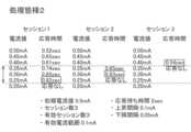
図8は、本実施形態の神経刺激測定装置の処理態様2の説明図である。処理態様2では、処理態様1と同じく、記憶部165に、初期電流値として0.5mA、既定のセッション数として3、既定の有効セッション数として3、既定の有効電流範囲として0.1mA、応答待ち時間として2sec、上昇間隔として0.1mA、下降間隔として0.05mAを記憶させている。In the case of processing mode 1, the effective current range is 0.1 mA, the number of effective sessions is 3, the three minimum current values stored are 0.25 mA, 0.30 mA, and 0.35 mA, and the three minimum current values for sessions 1 to 3 are All of the current values are within 0.1 mA of the available current range. That is, since there are minimum current values equal to or greater than the number of effective sessions within the effective current range, the
<Processing Mode 2>
FIG. 8 is an explanatory diagram of processing mode 2 of the nerve stimulation measurement apparatus of this embodiment. In processing mode 2, as in processing mode 1,
処理態様2は、処理態様1と同様の手順でセッション1~3の処理をする。すなわち、処理態様2の場合、既定のセッション数として3が設定されているので、制御部160はセッション3までの処理で、最小電流値の測定をする。セッション1~3までの処理で、セッション1の0.25mA、セッション2の0.30mA、セッション3の0.40mAという3つの最小電流値が測定される。 In processing mode 2, sessions 1 to 3 are processed in the same procedure as in processing mode 1. FIG. That is, in the case of processing mode 2, since 3 is set as the default number of sessions,
次に、処理態様1と同じく、制御部160は、記憶部165に記憶されている既定の有効電流範囲と既定の有効セッション数とを参照するとともに、以上のセッション1~3の処理において記憶した最小電流値を参照し、有効電流範囲内に有効セッション数以上の最小電流値があるか否かを判断する。 Next, as in the processing mode 1, the
処理態様2の場合、有効電流範囲は0.1mA、有効セッション数は3、記憶した3つの最小電流値は0.25mA、0.30mA、0.40mAであり、セッション1~3の3つの最小電流値の内の2つしか有効電流範囲の0.1mA以内に入っていない、つまり、有効電流範囲内に有効セッション数以上の最小電流値がないので、制御部160は、感覚閾値が測定不能である旨を、表示部154に表示させる。
<処理態様3>
図9は、本実施形態の神経刺激測定装置の処理態様3の説明図である。処理態様3では、記憶部165に、初期電流値として0.5mA、既定のセッション数として3、既定の有効セッション数として2、既定の有効電流範囲として0.1mA、応答待ち時間として2sec、上昇間隔として0.1mA、下降間隔として0.05mAを記憶させている。In the case of processing mode 2, the effective current range is 0.1 mA, the number of effective sessions is 3, the three minimum current values stored are 0.25 mA, 0.30 mA, and 0.40 mA, and the three minimum current values for sessions 1 to 3 are Only two of the current values are within the effective current range of 0.1 mA, that is, there is no minimum current value equal to or greater than the number of effective sessions within the effective current range, so the
<Processing Mode 3>
FIG. 9 is an explanatory diagram of processing mode 3 of the nerve stimulation measurement apparatus of this embodiment. In processing mode 3, the
処理態様3は、処理態様1と同様の手順でセッション1~3の処理をする。すなわち、処理態様3の場合、既定のセッション数として3が設定されているので、制御部160はセッション3までの処理で、最小電流値の測定を終了する。セッション1~3までの処理で、セッション1の0.25mA、セッション2の0.40mA、セッション3の0.40mAという3つの最小電流値が測定される。 In processing mode 3, sessions 1 to 3 are processed in the same procedure as in processing mode 1. FIG. That is, in the case of processing mode 3, since 3 is set as the default number of sessions, the
次に、処理態様1と同じく、制御部160は、記憶部165に記憶されている既定の有効電流範囲と既定の有効セッション数とを参照するとともに、以上のセッション1~3に処理において記憶した最小電流値を参照し、有効電流範囲内に有効セッション数以上の最小電流値があるか否かを判断する。 Next, as in the processing mode 1, the
処理態様3の場合、有効電流範囲は0.1mA、有効セッション数は2、記憶した3つの最小電流値は0.25mA、0.40mA、0.40mAであり、セッション1~3の3つの最小電流値の内の2つの最小電流値(セッション2と3)が有効電流範囲の0.1mA以内に入っている、つまり、有効電流範囲内に有効セッション数以上の最小電流値があるので、制御部160は、セッション2、3の最小電流値の内の最小の0.40mAを感覚閾値として表示部154に表示させる。
<処理態様4>
図10は、本実施形態の神経刺激測定装置の処理態様4の説明図である。処理態様4では、処理形態3と同じく、記憶部165に、初期電流値として0.5mA、既定のセッション数として3、既定の有効セッション数として2、既定の有効電流範囲として0.1mA、応答待ち時間として2sec、上昇間隔として0.1mA、下降間隔として0.05mAを記憶させている。In the case of processing mode 3, the effective current range is 0.1 mA, the number of effective sessions is 2, the three minimum current values stored are 0.25 mA, 0.40 mA, and 0.40 mA, and the three minimum current values for sessions 1 to 3 are Two of the minimum current values (sessions 2 and 3) are within the effective current range of 0.1 mA. The
<Processing Mode 4>
FIG. 10 is an explanatory diagram of processing mode 4 of the nerve stimulation measurement apparatus of this embodiment. In processing mode 4, as in processing mode 3,
処理態様4は、セッション処理を繰り返し、有効電流範囲内に有効セッション数以上の最小の刺激電流値があると判断されたときには、既定のセッション数のセッション処理が完了していなくとも、その時点で制御部160の測定が終了する。このため、処理態様4では、処理態様1~3に比較して測定時間が短くなる場合がある。 Processing mode 4 repeats session processing, and when it is determined that there is a minimum stimulation current value equal to or greater than the number of effective sessions within the effective current range, even if session processing for the predetermined number of sessions has not been completed, at that point The measurement of the
処理態様4は、処理態様1と同様の手順でセッション1の処理をする。すなわち、制御部160は、まず、初期電流値の0.5mAを初期刺激電流値として設定し、下降間隔として0.05mAずつ刺激電流値を減少させながら最小電流値を測定する。この測定で、セッション1の最小電流値として、0.25mAが測定される。 In processing mode 4, session 1 is processed in the same procedure as in processing mode 1. That is, the
次にセッション2の処理をする。すなわち、制御部160は、次回の刺激電流値として0.35mAを初期刺激電流値として設定し、下降間隔として0.05mAずつ刺激電流値を低下させながら最小電流値を測定する。この測定で、セッション2の最小電流値として、0.30mAが測定される。 Next, session 2 is processed. That is, the
次に、制御部160は、記憶部165に記憶されている既定の有効セッション数が2であるので、セッション1とセッション2で測定された最小電流値が有効電流範囲の0.1mA以内であるか否かを判断する。セッション1とセッション2で測定された最小電流値は、0.25mAと0.30mAであり、これらの最小電流値は有効電流範囲の0.1mA以内であるので、制御部160は、セッション3の測定処理は行わずに、有効電流範囲内の最小電流値の内で最小の0.25mAを感覚閾値として表示部154に表示させる。このように、有効電流範囲内の最小電流値が有効セッション数以上ある場合に、以降のセッションの実施を停止すると、検査時間が短く終わる。 Next, since the default number of valid sessions stored in the
以上に説明した、本実施形態の神経刺激測定装置、神経刺激測定方法および神経刺激測定プログラムによれば、スタートスイッチ152を押すだけで、制御部160が自動的に感覚閾値を測定するので、検査者の手間がかからなくなる。また、電気刺激を与えるタイミングが検査者に依らないので、再現性のある測定結果を得ることができる。 According to the nerve stimulation measuring device, the nerve stimulation measuring method, and the nerve stimulation measuring program of the present embodiment described above, simply by pressing the
以上、本発明の神経刺激測定装置、神経刺激測定方法および神経刺激測定プログラムを、実施形態を例示して説明した。しかし、本発明の神経刺激測定装置、神経刺激測定方法および神経刺激測定プログラムの技術的範囲は、以上の実施形態の記載に限定されるものではなく、当業者がこの技術的範囲内において改変できるあらゆる実施形態が含まれることは言うまでもない。 The neural stimulation measurement device, the neural stimulation measurement method, and the neural stimulation measurement program of the present invention have been described above by exemplifying the embodiments. However, the technical scope of the nerve stimulation measurement device, nerve stimulation measurement method, and nerve stimulation measurement program of the present invention is not limited to the description of the above embodiments, and those skilled in the art can make modifications within this technical scope. It goes without saying that any embodiment is included.
100 神経刺激測定装置、
110 電極部、
115 コード、
120 応答部、
122 応答ボタン、
125 コード、
150 本体部、
152 スタートスイッチ、
154 表示部、
156 入力部、
160 制御部、
162 CPU、
164 RAM、
165 記憶部、
166 ROM、
168 外部I/F。100 nerve stimulation measuring device,
110 electrode part,
115 code,
120 Responder;
122 response button,
125 code,
150 main body,
152 start switch,
154 display unit,
156 input section,
160 control unit,
162 CPUs,
164 RAM,
165 storage unit,
166 ROMs,
168 External I/F.
Claims (11)
Translated fromJapanese前記電極部に段階的に増加または減少する刺激電流を供給し、段階ごとの応答の状況から前記被検者が前記電気刺激を感じる刺激電流である感覚閾値を求める制御部と、を有し、
前記制御部は、
前記電極部に段階的に増加する刺激電流を供給する場合には既定の上昇間隔にしたがって段階的に前記刺激電流を増加させ、前記電極部に段階的に減少する前記刺激電流を供給する場合には既定の下降間隔にしたがって段階的に前記刺激電流を減少させ、
前記電極部に前記刺激電流の供給を応答が確認できなくなるまで繰り返し行って前記応答が確認できる最小の刺激電流である最小電流値を求めるセッション処理を行い、
前記最小電流値が既定の有効電流範囲内となるセッション数が既定の有効セッション数以上ある場合には、前記既定の有効電流範囲内の前記最小電流値を基に前記感覚閾値を求める、神経刺激測定装置。a response unit that responds when a subject wearing an electrode unit that provides electrical stimulation senses the electrical stimulation;
a control unit that supplies a stimulation current that increases or decreases stepwise to the electrode unit, andobtains a sensory threshold, which is the stimulation current that the subject feels the electrical stimulation from the state of response in each step,
The control unit
When supplying the stimulating current that increases stepwise to the electrode unit, the stimulating current is increased stepwise according to a predetermined rising interval, and when supplying the stimulating current that decreases stepwise to the electrode unit decreases the stimulation current stepwise according to a predetermined ramp-down interval,
performing session processing for obtaining a minimum current value, which is the minimum stimulation current at which the response can be confirmed by repeatedly supplying the stimulation current to the electrode unit until the response cannot be confirmed,
If the number of sessions in which the minimum current value is within a predetermined effective current range is equal to or greater than the predetermined number of effective sessions, the sensory threshold is obtained based on the minimum current value within the predetermined effective current range, nerve stimulation. measuring device.
既定のセッション数として実行される最大のセッション数を上限として前記セッション処理を繰り返し行う、請求項1に記載の神経刺激測定装置。The control unit
2. The nerve stimulation measuring apparatus according to claim1 , wherein said session processing is repeatedly performed with a maximum number of sessions executed as a predetermined number of sessions being an upper limit.
前記既定の有効電流範囲内の前記最小電流値が前記既定の有効セッション数以上ある場合には、以降のセッションの実施を停止する、請求項1または2に記載の神経刺激測定装置。The control unit
3. The nerve stimulation measuring apparatus according to claim1 , wherein when said minimum current value within said predetermined effective current range is equal to or greater than said predetermined number of effective sessions, execution of subsequent sessions is stopped.
前記既定の有効電流範囲内の前記最小電流値が前記既定の有効セッション数以上ない場合には、測定不能であるとする、請求項1から3のいずれかに記載の神経刺激測定装置。The control unit
4. The nerve stimulation measurement apparatus according to any one of claims1 to3 , wherein measurement is impossible when said minimum current value within said predetermined effective current range is less than said predetermined number of effective sessions.
前記既定の上昇間隔、前記既定の下降間隔、前記既定のセッション数、前記既定の有効セッション数、および前記既定の有効電流範囲を記憶する記憶部を有する、請求項2に記載の神経刺激測定装置。The control unit
3. The nerve stimulation measurement apparatus according to claim2 , further comprising a storage unit that stores the predetermined rising interval, the predetermined falling interval, the predetermined number of sessions, the predetermined number of effective sessions, and the predetermined effective current range. .
前記記憶部に記憶させる前記既定の上昇間隔、前記既定の下降間隔、前記既定のセッション数、前記既定の有効セッション数、および前記既定の有効電流範囲は、前記入力部から入力される、請求項5に記載の神経刺激測定装置。Furthermore, it has an input unit,
The predetermined rising interval, the predetermined falling interval, the predetermined number of sessions, the predetermined number of effective sessions, and the predetermined effective current range to be stored in the storage unit are input from the input unit. 5. The nerve stimulation measurement device according to5 .
前記制御部が求めた前記感覚閾値、または前記測定不能である旨は、前記表示部によって表示される、請求項4に記載の神経刺激測定装置。Furthermore, it has a display unit,
5. The nerve stimulation measurement apparatus according to claim4 , wherein the sensory threshold obtained by the control unit or the fact that the measurement is impossible is displayed by the display unit.
前記感覚閾値を、前記既定の有効電流範囲内のすべての前記最小電流値の最小値または最大値とするか、前記既定の有効電流範囲内のすべての前記最小電流値の平均値または中央値とする、請求項1~7のいずれかに記載の神経刺激測定装置。The control unit
The sensory threshold is the minimum or maximum value of all the minimum current values within the predetermined effective current range, or the average or median value of all the minimum current values within the predetermined effective current range. The nerve stimulation measuring device according to any one of claims1 to7 , wherein
前記制御部は、前記スタートスイッチが押されることによって、前記電極部への前記刺激電流の供給から前記感覚閾値を求めるまでの一連の処理を自動的に行う、請求項1~8のいずれかに記載の神経刺激測定装置。Furthermore, it has a start switch,
9. Any one of claims 1 to8 , wherein when the start switch is pressed, the control unit automatically performs a series of processes from supplying the stimulation current to the electrode unit to determining the sensory threshold. A nerve stimulation measurement device as described.
制御部が、前記電極部に段階的に増加または減少する刺激電流を供給し、段階ごとの応答の状況から前記被検者が前記電気刺激を感じる刺激電流である感覚閾値を求める段階であって、
前記制御部が、前記電極部に段階的に増加する刺激電流を供給する場合には既定の上昇間隔にしたがって段階的に前記刺激電流を増加させ、前記電極部に段階的に減少する前記刺激電流を供給する場合には既定の下降間隔にしたがって段階的に前記刺激電流を減少させ、
前記電極部に前記刺激電流の供給を応答が確認できなくなるまで繰り返し行って前記応答が確認できる最小の刺激電流である最小電流値を求めるセッション処理を行い、
前記最小電流値が既定の有効電流範囲内となるセッション数が既定の有効セッション数以上ある場合には、前記既定の有効電流範囲内の前記最小電流値を基に前記感覚閾値を求める段階と、を有する
神経刺激測定方法。a step in which the response unit responds when a subject wearing an electrode unit that provides electrical stimulation senses the electrical stimulation;
A step in which a control unit supplies a stimulation current that increases or decreases stepwise to the electrode unit, andobtains a sensory threshold, which is a stimulation current at which the subject feels the electrical stimulation, from the state of response in each step,,
When the control unit supplies a stepwise increasing stimulation current to the electrode unit, the stimulation current is stepwise increased according to a predetermined rising interval, and the stimulation current is stepwise decreased to the electrode unit. when supplying the stimulation current stepwise according to a predetermined falling interval,
performing session processing for obtaining a minimum current value, which is the minimum stimulation current at which the response can be confirmed by repeatedly supplying the stimulation current to the electrode unit until the response cannot be confirmed,
determining the sensory threshold based on the minimum current value within the predetermined effective current range, if the number of sessions in which the minimum current value is within the predetermined effective current range is equal to or greater than the predetermined effective number of sessions; A nerve stimulation measurement method.
応答部が、電気刺激を与える電極部が装着された被検者が前記電気刺激を感じた場合に応答する段階と、
制御部が、前記電極部に段階的に増加または減少する刺激電流を供給し、段階ごとの応答の状況から前記被検者が前記電気刺激を感じる刺激電流である感覚閾値を求める段階であって、
前記制御部が、前記電極部に段階的に増加する刺激電流を供給する場合には既定の上昇間隔にしたがって段階的に前記刺激電流を増加させ、前記電極部に段階的に減少する前記刺激電流を供給する場合には既定の下降間隔にしたがって段階的に前記刺激電流を減少させ、
前記電極部に前記刺激電流の供給を応答が確認できなくなるまで繰り返し行って前記応答が確認できる最小の刺激電流である最小電流値を求めるセッション処理を行い、
前記最小電流値が既定の有効電流範囲内となるセッション数が既定の有効セッション数以上ある場合には、前記既定の有効電流範囲内の前記最小電流値を基に前記感覚閾値を求める段階と、
を実行させるための、神経刺激測定プログラム。to the computer,
a step in which the response unit responds when a subject wearing an electrode unit that provides electrical stimulation senses the electrical stimulation;
A step in which a control unit supplies a stimulation current that increases or decreases stepwise to the electrode unit, andobtains a sensory threshold, which is a stimulation current at which the subject feels the electrical stimulation, from the state of response in each step,,
When the control unit supplies a stepwise increasing stimulation current to the electrode unit, the stimulation current is stepwise increased according to a predetermined rising interval, and the stimulation current is stepwise decreased to the electrode unit. when supplying the stimulation current stepwise according to a predetermined falling interval,
performing session processing for obtaining a minimum current value, which is the minimum stimulation current at which the response can be confirmed by repeatedly supplying the stimulation current to the electrode unit until the response cannot be confirmed,
determining the sensory threshold based on the minimum current value within the predetermined effective current range, if the number of sessions in which the minimum current value is within the predetermined effective current range is equal to or greater than the predetermined effective number of sessions;
Nerve stimulation measurement program for executing
Priority Applications (2)
| Application Number | Priority Date | Filing Date | Title |
|---|---|---|---|
| JP2019091281AJP7278864B2 (en) | 2019-05-14 | 2019-05-14 | Nerve Stimulation Measuring Device, Nerve Stimulation Measuring Method and Nerve Stimulation Measuring Program |
| EP20171830.1AEP3738647B1 (en) | 2019-05-14 | 2020-04-28 | Nerve stimulation measurement device, nerve stimulation measurement method, and nerve stimulation measurement program |
Applications Claiming Priority (1)
| Application Number | Priority Date | Filing Date | Title |
|---|---|---|---|
| JP2019091281AJP7278864B2 (en) | 2019-05-14 | 2019-05-14 | Nerve Stimulation Measuring Device, Nerve Stimulation Measuring Method and Nerve Stimulation Measuring Program |
Publications (2)
| Publication Number | Publication Date |
|---|---|
| JP2020185136A JP2020185136A (en) | 2020-11-19 |
| JP7278864B2true JP7278864B2 (en) | 2023-05-22 |
Family
ID=70476024
Family Applications (1)
| Application Number | Title | Priority Date | Filing Date |
|---|---|---|---|
| JP2019091281AActiveJP7278864B2 (en) | 2019-05-14 | 2019-05-14 | Nerve Stimulation Measuring Device, Nerve Stimulation Measuring Method and Nerve Stimulation Measuring Program |
Country Status (2)
| Country | Link |
|---|---|
| EP (1) | EP3738647B1 (en) |
| JP (1) | JP7278864B2 (en) |
Citations (4)
| Publication number | Priority date | Publication date | Assignee | Title |
|---|---|---|---|---|
| JP2010088802A (en) | 2008-10-10 | 2010-04-22 | National Institutes Of Natural Sciences | Pain sensory nerve stimulation apparatus |
| JP2014533525A (en) | 2011-11-15 | 2014-12-15 | ニューロメトリックス・インコーポレーテッド | Apparatus and method for reducing pain using transcutaneous electrical nerve stimulation |
| US20180064362A1 (en) | 2015-03-19 | 2018-03-08 | Aalborg Universitet | Assessment of nerve fiber excitability |
| US20190001135A1 (en) | 2017-07-02 | 2019-01-03 | The Governing Council Of The University Of Toronto | Systems and methods for providing patient signaling and contingent stimulation |
Family Cites Families (1)
| Publication number | Priority date | Publication date | Assignee | Title |
|---|---|---|---|---|
| US5806522A (en)* | 1995-08-15 | 1998-09-15 | Katims; Jefferson Jacob | Digital automated current perception threshold (CPT) determination device and method |
- 2019
- 2019-05-14JPJP2019091281Apatent/JP7278864B2/enactiveActive
- 2020
- 2020-04-28EPEP20171830.1Apatent/EP3738647B1/enactiveActive
Patent Citations (4)
| Publication number | Priority date | Publication date | Assignee | Title |
|---|---|---|---|---|
| JP2010088802A (en) | 2008-10-10 | 2010-04-22 | National Institutes Of Natural Sciences | Pain sensory nerve stimulation apparatus |
| JP2014533525A (en) | 2011-11-15 | 2014-12-15 | ニューロメトリックス・インコーポレーテッド | Apparatus and method for reducing pain using transcutaneous electrical nerve stimulation |
| US20180064362A1 (en) | 2015-03-19 | 2018-03-08 | Aalborg Universitet | Assessment of nerve fiber excitability |
| US20190001135A1 (en) | 2017-07-02 | 2019-01-03 | The Governing Council Of The University Of Toronto | Systems and methods for providing patient signaling and contingent stimulation |
Also Published As
| Publication number | Publication date |
|---|---|
| EP3738647B1 (en) | 2024-05-15 |
| JP2020185136A (en) | 2020-11-19 |
| EP3738647A1 (en) | 2020-11-18 |
Similar Documents
| Publication | Publication Date | Title |
|---|---|---|
| US10512588B2 (en) | Sexual stimulating system and method with feedback control | |
| JP7066360B2 (en) | Electrical muscle stimulator | |
| JP7278864B2 (en) | Nerve Stimulation Measuring Device, Nerve Stimulation Measuring Method and Nerve Stimulation Measuring Program | |
| CN105167743B (en) | Physical condition evaluating apparatus and the massager for having the device | |
| US20050154329A1 (en) | Pain measurement system and method of measuring pain | |
| US20080058685A1 (en) | Electronic Pulse Massage Apparatus Capable of Measuring Temperature | |
| US20220152384A1 (en) | Biometric measurement system, and computer-readable non-transitory storage medium | |
| CN112642059B (en) | Programmable device and system for selectively testing directional electrode treatment window | |
| JP5258434B2 (en) | Massage machine | |
| CN110876672B (en) | Massaging machine | |
| JP2020146208A5 (en) | Treatment equipment, control methods for treatment equipment, and control programs for treatment equipment | |
| JP7048227B2 (en) | Perception test device | |
| EP3184034A1 (en) | Muscular relaxation monitoring device, muscular relaxation monitoring method and muscular relaxation monitoring program | |
| CN102274026B (en) | Biological information measuring device and input detection method thereof | |
| JP7412960B2 (en) | Muscle relaxation monitoring device and calibration processing method | |
| TWI900370B (en) | System and method of controlling stimulation signal | |
| JP6395769B2 (en) | Blood flow measurement device, calculation system, calculation method, calculation program, blood flow measurement method, and blood flow measurement program | |
| KR102430159B1 (en) | Adaptive Sole Electrical Stimulation Device and Method Using Thereof | |
| KR102160875B1 (en) | Brain training apparatus through compound stimulus and method thereof | |
| JP7338223B2 (en) | Exercise support system, exercise support device, exercise support method, and exercise support program | |
| CN116510181B (en) | Vagus nerve stimulation system | |
| RU2128038C1 (en) | Reflexotherapy device | |
| JP2007175284A (en) | Massaging machine | |
| JP2023132324A (en) | Estimation device, estimation system, and estimation method | |
| JP2023035682A (en) | Operation control device, operation control method, and program |
Legal Events
| Date | Code | Title | Description |
|---|---|---|---|
| A621 | Written request for application examination | Free format text:JAPANESE INTERMEDIATE CODE: A621 Effective date:20220426 | |
| A977 | Report on retrieval | Free format text:JAPANESE INTERMEDIATE CODE: A971007 Effective date:20230130 | |
| A131 | Notification of reasons for refusal | Free format text:JAPANESE INTERMEDIATE CODE: A131 Effective date:20230207 | |
| A521 | Request for written amendment filed | Free format text:JAPANESE INTERMEDIATE CODE: A523 Effective date:20230407 | |
| TRDD | Decision of grant or rejection written | ||
| A01 | Written decision to grant a patent or to grant a registration (utility model) | Free format text:JAPANESE INTERMEDIATE CODE: A01 Effective date:20230425 | |
| A61 | First payment of annual fees (during grant procedure) | Free format text:JAPANESE INTERMEDIATE CODE: A61 Effective date:20230510 | |
| R150 | Certificate of patent or registration of utility model | Ref document number:7278864 Country of ref document:JP Free format text:JAPANESE INTERMEDIATE CODE: R150 |