JP7273232B2 - heater assembly and container - Google Patents
heater assembly and containerDownload PDFInfo
- Publication number
- JP7273232B2 JP7273232B2JP2022162899AJP2022162899AJP7273232B2JP 7273232 B2JP7273232 B2JP 7273232B2JP 2022162899 AJP2022162899 AJP 2022162899AJP 2022162899 AJP2022162899 AJP 2022162899AJP 7273232 B2JP7273232 B2JP 7273232B2
- Authority
- JP
- Japan
- Prior art keywords
- container
- generating article
- channel
- flavor
- peripheral surface
- Prior art date
- Legal status (The legal status is an assumption and is not a legal conclusion. Google has not performed a legal analysis and makes no representation as to the accuracy of the status listed.)
- Active
Links
Images


Classifications
- A—HUMAN NECESSITIES
- A24—TOBACCO; CIGARS; CIGARETTES; SIMULATED SMOKING DEVICES; SMOKERS' REQUISITES
- A24F—SMOKERS' REQUISITES; MATCH BOXES; SIMULATED SMOKING DEVICES
- A24F40/00—Electrically operated smoking devices; Component parts thereof; Manufacture thereof; Maintenance or testing thereof; Charging means specially adapted therefor
- A24F40/40—Constructional details, e.g. connection of cartridges and battery parts
- A24F40/42—Cartridges or containers for inhalable precursors
- A—HUMAN NECESSITIES
- A24—TOBACCO; CIGARS; CIGARETTES; SIMULATED SMOKING DEVICES; SMOKERS' REQUISITES
- A24F—SMOKERS' REQUISITES; MATCH BOXES; SIMULATED SMOKING DEVICES
- A24F40/00—Electrically operated smoking devices; Component parts thereof; Manufacture thereof; Maintenance or testing thereof; Charging means specially adapted therefor
- A24F40/40—Constructional details, e.g. connection of cartridges and battery parts
- A24F40/46—Shape or structure of electric heating means
- A—HUMAN NECESSITIES
- A24—TOBACCO; CIGARS; CIGARETTES; SIMULATED SMOKING DEVICES; SMOKERS' REQUISITES
- A24F—SMOKERS' REQUISITES; MATCH BOXES; SIMULATED SMOKING DEVICES
- A24F40/00—Electrically operated smoking devices; Component parts thereof; Manufacture thereof; Maintenance or testing thereof; Charging means specially adapted therefor
- A24F40/40—Constructional details, e.g. connection of cartridges and battery parts
- A24F40/48—Fluid transfer means, e.g. pumps
- A24F40/485—Valves; Apertures
- A—HUMAN NECESSITIES
- A24—TOBACCO; CIGARS; CIGARETTES; SIMULATED SMOKING DEVICES; SMOKERS' REQUISITES
- A24F—SMOKERS' REQUISITES; MATCH BOXES; SIMULATED SMOKING DEVICES
- A24F40/00—Electrically operated smoking devices; Component parts thereof; Manufacture thereof; Maintenance or testing thereof; Charging means specially adapted therefor
- A24F40/50—Control or monitoring
- A24F40/51—Arrangement of sensors
- A—HUMAN NECESSITIES
- A24—TOBACCO; CIGARS; CIGARETTES; SIMULATED SMOKING DEVICES; SMOKERS' REQUISITES
- A24F—SMOKERS' REQUISITES; MATCH BOXES; SIMULATED SMOKING DEVICES
- A24F40/00—Electrically operated smoking devices; Component parts thereof; Manufacture thereof; Maintenance or testing thereof; Charging means specially adapted therefor
- A24F40/50—Control or monitoring
- A24F40/53—Monitoring, e.g. fault detection
- A—HUMAN NECESSITIES
- A24—TOBACCO; CIGARS; CIGARETTES; SIMULATED SMOKING DEVICES; SMOKERS' REQUISITES
- A24F—SMOKERS' REQUISITES; MATCH BOXES; SIMULATED SMOKING DEVICES
- A24F40/00—Electrically operated smoking devices; Component parts thereof; Manufacture thereof; Maintenance or testing thereof; Charging means specially adapted therefor
- A24F40/50—Control or monitoring
- A24F40/57—Temperature control
- A—HUMAN NECESSITIES
- A24—TOBACCO; CIGARS; CIGARETTES; SIMULATED SMOKING DEVICES; SMOKERS' REQUISITES
- A24F—SMOKERS' REQUISITES; MATCH BOXES; SIMULATED SMOKING DEVICES
- A24F40/00—Electrically operated smoking devices; Component parts thereof; Manufacture thereof; Maintenance or testing thereof; Charging means specially adapted therefor
- A24F40/70—Manufacture
- A—HUMAN NECESSITIES
- A61—MEDICAL OR VETERINARY SCIENCE; HYGIENE
- A61M—DEVICES FOR INTRODUCING MEDIA INTO, OR ONTO, THE BODY; DEVICES FOR TRANSDUCING BODY MEDIA OR FOR TAKING MEDIA FROM THE BODY; DEVICES FOR PRODUCING OR ENDING SLEEP OR STUPOR
- A61M15/00—Inhalators
- A61M15/06—Inhaling appliances shaped like cigars, cigarettes or pipes
- H—ELECTRICITY
- H05—ELECTRIC TECHNIQUES NOT OTHERWISE PROVIDED FOR
- H05B—ELECTRIC HEATING; ELECTRIC LIGHT SOURCES NOT OTHERWISE PROVIDED FOR; CIRCUIT ARRANGEMENTS FOR ELECTRIC LIGHT SOURCES, IN GENERAL
- H05B3/00—Ohmic-resistance heating
- H05B3/0019—Circuit arrangements
- H—ELECTRICITY
- H05—ELECTRIC TECHNIQUES NOT OTHERWISE PROVIDED FOR
- H05B—ELECTRIC HEATING; ELECTRIC LIGHT SOURCES NOT OTHERWISE PROVIDED FOR; CIRCUIT ARRANGEMENTS FOR ELECTRIC LIGHT SOURCES, IN GENERAL
- H05B3/00—Ohmic-resistance heating
- H05B3/40—Heating elements having the shape of rods or tubes
- A—HUMAN NECESSITIES
- A24—TOBACCO; CIGARS; CIGARETTES; SIMULATED SMOKING DEVICES; SMOKERS' REQUISITES
- A24F—SMOKERS' REQUISITES; MATCH BOXES; SIMULATED SMOKING DEVICES
- A24F40/00—Electrically operated smoking devices; Component parts thereof; Manufacture thereof; Maintenance or testing thereof; Charging means specially adapted therefor
- A24F40/20—Devices using solid inhalable precursors
Landscapes
- Health & Medical Sciences (AREA)
- Engineering & Computer Science (AREA)
- General Health & Medical Sciences (AREA)
- Pulmonology (AREA)
- Anesthesiology (AREA)
- Biomedical Technology (AREA)
- Heart & Thoracic Surgery (AREA)
- Hematology (AREA)
- Life Sciences & Earth Sciences (AREA)
- Animal Behavior & Ethology (AREA)
- Bioinformatics & Cheminformatics (AREA)
- Public Health (AREA)
- Veterinary Medicine (AREA)
- Cookers (AREA)
- Disinfection, Sterilisation Or Deodorisation Of Air (AREA)
- Packages (AREA)
- Apparatus For Making Beverages (AREA)
- External Artificial Organs (AREA)
- Seasonings (AREA)
- Manufacture Of Tobacco Products (AREA)
- Passenger Equipment (AREA)
- Resistance Heating (AREA)
- Glass Compositions (AREA)
Description
Translated fromJapanese本発明は、香味吸引器で用いるヒータアッセンブリ及び容器に関する。 The present invention relates to heater assemblies and containers for use in flavor inhalers.
従来、燃焼を伴わずに香味発生物品を加熱する香味吸引器が知られている。香味吸引器は、香味発生物品を収容するチャンバと、チャンバに収容される香味発生物品を加熱するヒータとを有する(例えば、特許文献1-3)。 Conventionally, flavor inhalers are known that heat flavor-generating articles without combustion. A flavor inhaler has a chamber containing a flavor generating article and a heater for heating the flavor generating article contained in the chamber (eg Patent Documents 1 to 3).
第1の特徴は、ヒータアッセンブリであって、香味発生物品を収容するチャンバを形成する筒状部分を有する容器と、前記筒状部分の周面に配置されるヒータとを備え、前記容器は、前記筒状部分の長手方向に沿って延在しており、かつ、前記筒状部分の長手方向と交差する方向で前記チャンバに隣接する第1チャネルと、前記筒状部分の長手方向に沿って前記チャンバ内を通る第2チャネルとを備え、前記第1チャネルは、前記2チャネルと連通することを要旨とする。 A first feature is a heater assembly, comprising: a container having a tubular portion forming a chamber for containing a flavor generating article; a first channel extending along the longitudinal direction of the tubular portion and adjacent to the chamber in a direction transverse to the longitudinal direction of the tubular portion; and along the longitudinal direction of the tubular portion. and a second channel passing through the chamber, wherein the first channel communicates with the two channels.
第2の特徴は、第1の特徴において、前記ヒータは、前記筒状部分の外周面に接触するように配置されることを要旨とする。 A gist of a second feature is that in the first feature, the heater is arranged so as to be in contact with an outer peripheral surface of the tubular portion.
第3の特徴は、第1の特徴又は第2の特徴において、前記ヒータは、加熱要素と、前記加熱要素を支持する基材とを有し、前記加熱要素は、前記筒状部分の周面における、前記第1チャネルと隣接する部分以外の配置対象部分に沿って設けられることを要旨とする。 A third feature is that in the first feature or the second feature, the heater has a heating element and a base material that supports the heating element, and the heating element is a peripheral surface of the tubular portion. 3, provided along an arrangement target portion other than the portion adjacent to the first channel.
第4の特徴は、第3の特徴において、前記配置対象部分は、前記筒状部分の周面において、第1配置部分と、前記第1配置部分よりも前記第1チャネルから離れた第2配置部分とを含み、前記第1配置部分における前記加熱要素のワット密度は、前記第2配置部分における前記加熱要素のワット密度よりも高いことを要旨とする。 A fourth feature is the third feature, wherein the portion to be arranged includes a first arranged portion and a second arranged portion further away from the first channel than the first arranged portion on the peripheral surface of the cylindrical portion. and wherein the watt density of the heating element in the first disposed portion is higher than the watt density of the heating element in the second disposed portion.
第5の特徴は、第1の特徴乃至第4の特徴のいずれかにおいて、前記ヒータは、加熱要素と、前記加熱要素を支持する基材とを有し、前記筒状部分は、前記香味発生物品を受け入れる第1端部と、前記筒状部分の長手方向において前記第1端部の反対側に設けられる第2端部とを有しており、前記加熱要素は、前記第2端部から離間するように、前記筒状部分の周面に沿って設けられることを要旨とする。 A fifth feature is that in any one of the first to fourth features, the heater has a heating element and a base material for supporting the heating element, and the tubular portion includes the flavor-generating The heating element has a first end for receiving an article and a second end longitudinally opposite the first end of the tubular portion, wherein the heating element extends from the second end. The gist is that they are provided along the peripheral surface of the cylindrical portion so as to be separated from each other.
第6の特徴は、第5の特徴において、前記容器は、前記第2端部を塞ぐ底板部分を有しており、前記加熱要素は、前記底板部分に設けられることなく、前記筒状部分の周面に沿って設けられることを要旨とする。 A sixth feature is that in the fifth feature, the container has a bottom plate portion that closes the second end, and the heating element is not provided in the bottom plate portion, but in the cylindrical portion. The gist is that it is provided along the peripheral surface.
第7の特徴は、第1の特徴乃至第6の特徴のいずれかにおいて、前記筒状部分は、前記香味発生物品が前記チャンバに収容されたときに前記香味発生物品の先端部に当接する当接部を有することを要旨とする。 A seventh feature is that, in any one of the first to sixth features, the tubular portion contacts the tip of the flavor generating article when the flavor generating article is accommodated in the chamber. The gist is to have a contact part.
第8の特徴は、第1の特徴乃至第6の特徴のいずれかにおいて、前記容器は、底板部分を有しており、前記容器の前記底板部分に設けられ、前記香味発生物品が前記チャンバに収容されたときに前記香味発生物品の先端部に当接する台座であって、前記台座の周りに前記第1チャネルおよび前記第2チャネルと連通する環状の隙間を形成する台座をさらに備えることを要旨とする。 According to an eighth feature, in any one of the first to sixth features, the container has a bottom plate portion, the bottom plate portion of the container is provided, and the flavor generating article is placed in the chamber. The gist of further comprising a pedestal that abuts against the tip of the flavor-generating article when housed, the pedestal forming an annular gap around the pedestal that communicates with the first channel and the second channel. and
第9の特徴は、第1の特徴乃至第8の特徴のいずれかにおいて、前記筒状部分は、熱伝導性部材によって構成されることを要旨とする。 The gist of the ninth feature is that in any one of the first to eighth features, the cylindrical portion is made of a thermally conductive member.
第10の特徴は、第1の特徴乃至第9の特徴のいずれかにおいて、前記筒状部分は、前記香味発生物品を受け入れる第1端部と、前記筒状部分の長手方向において前記第1端部の反対側に設けられる第2端部とを有しており、前記容器は、前記第2端部を塞ぐ底板部分を有しており、前記筒状部分は、前記第1チャネルと前記第2チャネルとを連通させる第3チャネルを有することを要旨とする。 A tenth feature is that in any one of the first to ninth features, the tubular portion has a first end for receiving the flavor generating article and a first end in the longitudinal direction of the tubular portion. and a second end provided opposite a portion, the container having a bottom plate portion closing the second end, and the tubular portion connecting the first channel and the first channel. The gist is to have a third channel that communicates with the two channels.
第11の特徴は、第10の特徴において、前記第1チャネルから前記第3チャネルに至るチャネルは、傾斜チャネル又は湾曲チャネルを含むことを要旨とする。 An eleventh feature is the tenth feature, wherein the channel from the first channel to the third channel includes an inclined channel or a curved channel.
第12の特徴は、第1の特徴乃至第11の特徴のいずれかにおいて、前記筒状部分は、前記筒状部分の長手方向に対する直交断面において、前記チャンバを区画する第1部分と、前記チャンバよりも外側に張り出す第2部分を含み、前記第2部分は、前記筒状部分の長手方向に沿って延びるとともに前記第1チャネルを形成することを要旨とする。 A twelfth feature is that in any one of the first to eleventh features, the tubular portion includes, in a cross section orthogonal to the longitudinal direction of the tubular portion, a first portion that partitions the chamber; The gist of the invention includes a second portion extending outwardly from the tubular portion, the second portion extending along the longitudinal direction of the tubular portion and forming the first channel.
第13の特徴は、第12の特徴において、前記チャンバに前記香味発生物品が収容された状態において、前記第1部分は、前記香味発生物品の外周面と接触し、前記第2部分は、前記香味発生物品の外周面から離間することを要旨とする。 A thirteenth feature is the thirteenth feature, in the twelfth feature, in a state in which the flavor-generating article is housed in the chamber, the first portion is in contact with the outer peripheral surface of the flavor-generating article, and the second portion is in contact with the flavor-generating article. The gist is to separate from the outer peripheral surface of the flavor-generating article.
第14の特徴は、第12の特徴又は第13の特徴において、前記第1部分は、前記香味発生物品が前記チャンバに収容されたときに、前記香味発生物品を前記第1部分と前記第2部分の配列方向において少なくとも部分的に圧縮するように構成されている。 A fourteenth feature is the twelfth or thirteenth feature, wherein the first portion separates the flavor-generating article from the first portion and the second portion when the flavor-generating article is housed in the chamber. It is configured to at least partially compress in the direction of arrangement of the portions.
第15の特徴は、第12の特徴乃至第14の特徴のいずれかにおいて、前記第1部分は、前記筒状部分の長手方向に対する横断面において、楕円形の円周を有していることを要旨とする。 A fifteenth feature is any one of the twelfth to fourteenth features, wherein the first portion has an elliptical circumference in a cross section with respect to the longitudinal direction of the cylindrical portion. This is the gist.
第16の特徴は、第1の特徴乃至第11の特徴のいずれかにおいて、前記容器は、前記第1チャネルを形成するチャネル形成部材を有しており、前記チャネル形成部材は、前記筒状部分の外周面に設けられることを要旨とする。 A sixteenth feature is any one of the first to eleventh features, wherein the container has a channel-forming member that forms the first channel, and the channel-forming member comprises the tubular portion. The gist is that it is provided on the outer peripheral surface of the.
第17の特徴は、第6の特徴、第6の特徴を引用する第7の特徴乃至第16の特徴のいずれかにおいて、前記ヒータアッセンブリは、前記ヒータアッセンブリ内で生じた温度変化の検出に用いるセンサを備え、前記センサは、前記底板部分に設けられることを要旨とする。 The seventeenth feature is the sixth feature, any one of the seventh to sixteenth features citing the sixth feature, wherein the heater assembly is used to detect a temperature change occurring within the heater assembly. A sensor is provided, and the sensor is provided on the bottom plate portion.
第18の特徴は、第12の特徴乃至第15の特徴のいずれかにおいて、前記ヒータアッセンブリは、前記ヒータアッセンブリ内で生じた温度変化の検出に用いるセンサを備え、前記センサは、前記第2部分に設けられることを要旨とする。 According to an eighteenth feature, in any one of the twelfth to fifteenth features, the heater assembly includes a sensor used to detect temperature changes occurring within the heater assembly, and the sensor is the second portion. The gist is that it is provided in
第19の特徴は、第16の特徴において、前記ヒータアッセンブリは、前記ヒータアッ
センブリ内で生じた温度変化の検出に用いるセンサを備え、前記センサは、前記チャネル形成部材に設けられることを要旨とする。A nineteenth aspect is characterized in that, in the sixteenth aspect, the heater assembly includes a sensor used for detecting a temperature change occurring within the heater assembly, and the sensor is provided on the channel forming member. .
第20の特徴は、第1の特徴乃至第19の特徴のいずれかにおいて、前記容器は、前記筒状部分の内周面の少なくとも一部に形成された、前記筒状容器の外周面よりも熱放射率の高い領域を有していることを要旨とする。 A twentieth feature is that in any one of the first to nineteenth features, the container is formed on at least a part of the inner peripheral surface of the tubular portion, and the outer peripheral surface of the tubular container is The gist is to have a region with high thermal emissivity.
第21の特徴は、第1の特徴乃至第20の特徴のいずれかにおいて、前記容器は、さらに底板部分を有しており、前記容器の前記筒状部分及び前記底板部分を覆う断熱部材をさらに備えることを要旨とする。 A twenty-first feature is that in any one of the first to twentieth features, the container further has a bottom plate portion, and further includes a heat insulating member covering the cylindrical portion and the bottom plate portion of the container. The gist of it is to be prepared.
第22の特徴は、第1の特徴乃至第21の特徴のいずれかにおいて、前記筒状部分と前記ヒータとの間に設けられた、前記筒状部材よりも熱伝導率の高い材料からなる膜をさらに備えることを要旨とする。 A twenty-second feature is, in any one of the first to twenty-first features, a film made of a material having higher thermal conductivity than the tubular member, provided between the tubular portion and the heater. The gist is to further provide
第23の特徴は、第1の特徴乃至第22の特徴のいずれかにおいて、前記第1チャネルが、前記ヒータアッセンブリの外部から前記第2チャネルに向かう空気流路を形成し、前記第1チャネルの逆方向の流体流れを阻害する阻害部材をさらに備えることを要旨とする。 A twenty-third feature is that in any one of the first to twenty-second features, the first channel forms an air flow path from the outside of the heater assembly toward the second channel, and the first channel The gist of the invention is that it further comprises an inhibition member that inhibits fluid flow in the reverse direction.
第24の特徴は、第23の特徴において、前記阻害部材は、前記第1チャネルの一部を塞ぐ隔壁であることを要旨とする。 A twenty-fourth feature is characterized in that, in the twenty-third feature, the blocking member is a partition wall that blocks a portion of the first channel.
第25の特徴は、第23の特徴において、前記容器の開口を露出させる第1位置と前記開口を覆う第2位置との間で移動可能な蓋部材をさらに備え、前記阻害部材は、前記第1位置に在る前記蓋部材であることを要旨とする。 A twenty-fifth feature is the twenty-third feature, further comprising a lid member movable between a first position exposing the opening of the container and a second position covering the opening, wherein the blocking member The gist is that the lid member is located at one position.
第26の特徴は、香味発生物品を収容するチャンバを形成する筒状部分を有する容器であって、前記筒状部分の長手方向に沿って延在しており、かつ、前記筒状部分の長手方向と交差する方向で前記チャンバに隣接する第1チャネルと、前記筒状部分の長手方向に沿って前記チャンバ内を通る第2チャネルとを備え、前記筒状部分の周面は、ヒータが配置される面を構成しており、前記第1チャネルは、前記2チャネルと連通することを要旨とする。 A twenty-sixth feature is a container having a tubular portion forming a chamber for containing a flavor generating article, the tubular portion extending along the longitudinal direction of the tubular portion and the length of the tubular portion. a first channel adjoining said chamber in a direction transverse to said direction and a second channel passing through said chamber along a longitudinal direction of said tubular portion, the peripheral surface of said tubular portion being disposed with a heater; The gist is that the first channel communicates with the two channels.
以下において、実施形態について説明する。なお、以下の図面の記載において、同一又は類似の部分には、同一又は類似の符号を付している。但し、図面は模式的なものであり、各寸法の比率などは現実のものとは異なる場合があることに留意すべきである。 Embodiments will be described below. In addition, in the following description of the drawings, the same or similar reference numerals are given to the same or similar parts. However, it should be noted that the drawings are schematic, and the ratio of each dimension may differ from the actual one.
従って、具体的な寸法などは以下の説明を参酌して判断すべきものである。また、図面相互間においても互いの寸法の関係や比率が異なる部分が含まれる場合があることは勿論である。 Therefore, specific dimensions should be determined with reference to the following description. In addition, it is needless to say that the drawings may include portions having different dimensional relationships and ratios.
[開示の概要]
上述した背景技術の香味吸引器では、チャンバに空気を取り入れるためのチャネル及びヒータの配置について様々な工夫がなされている。しかしながら、香味吸引器が小型であり、エアロゾルを効率的に発生する観点では、チャネル及びヒータの配置について更なる改善が望まれている。[Summary of Disclosure]
In the above-described background art flavor inhalers, various ideas have been devised for the arrangement of the heater and the channel for introducing air into the chamber. However, the flavor inhaler is small, and from the viewpoint of efficiently generating an aerosol, it is desired to further improve the arrangement of channels and heaters.
開示の概要に係るヒータアッセンブリは、香味発生物品を収容するチャンバを形成する筒状部分を有する容器と、前記筒状部分の周面に配置されるヒータとを備える。前記容器は、前記筒状部分の長手方向に沿って延在しており、かつ、前記筒状部分の長手方向と交差する方向で前記チャンバに隣接する第1チャネルと、前記筒状部分の長手方向に沿って前記チャンバ内を通る第2チャネルとを備える。前記第1チャネルは、前記2チャネルと連通する。 A heater assembly according to the summary of the disclosure includes a container having a tubular portion defining a chamber for containing a flavor-generating article, and a heater disposed around the tubular portion. The container has a first channel extending along the longitudinal direction of the tubular portion and adjoining the chamber in a direction transverse to the longitudinal direction of the tubular portion, and a longitudinal direction of the tubular portion. and a second channel extending longitudinally through said chamber. The first channel communicates with the second channel.
開示の概要では、チャンバを形成する筒状部分の周面にヒータが配置されることを前提として、チャンバ内を通る第2チャネルに連通する第1チャネルがチャンバに隣接する。このような構成によれば、筒状部分の長手方向においてヒータアッセンブリの下方に連通するチャネルを設ける必要がなく、ヒータアッセンブリの底面を閉鎖する構造を採用することができる。従って、ヒータアッセンブリの下方のデッドスペースを有効に利用することができる。 In summary of the disclosure, the chamber is adjoined by a first channel that communicates with a second channel that passes through the chamber, provided that the heater is disposed about the circumference of the cylindrical portion that forms the chamber. According to such a configuration, there is no need to provide a channel that communicates with the lower portion of the heater assembly in the longitudinal direction of the cylindrical portion, and a structure that closes the bottom surface of the heater assembly can be adopted. Therefore, the dead space below the heater assembly can be effectively utilized.
[実施形態]
(香味吸引器)
以下において、実施形態に係る香味吸引器について説明する。図1は、実施形態に係る香味吸引器100を示す図である。[Embodiment]
(flavor aspirator)
A flavor inhaler according to an embodiment will be described below. FIG. 1 is a diagram showing a
図1に示すように、香味吸引器100は、香味発生物品110と、吸引器本体120とを有する。実施形態では、香味発生物品110をユーザが咥えた状態でパフ動作が行われるケースを例示する。ユーザが吸い込む空気は、空気流100A、空気流100C、空気流100Bの順でユーザの口腔内に導かれる。 As shown in FIG. 1 , the
香味発生物品110は、香味を発生しうる成分を含む基材であり、長手方向に沿って延びる柱状形状を有する。例えば、香味発生物品110は、刻みたばこ、たばこ原料を粒状に成形した成形体、たばこ原料をシート状に成形した成形体などによって構成されてもよい。香味発生物品110は、加熱に伴ってエアロゾルを発生してもよく、エアロゾルの発生を促進するためにグリセリン、プロピレングリコール、又は1,3-ブタンジオールなどの各種ポリオールを含むエアロゾル源を含んでもよい。香味発生物品110は、たばこ以外の植物(例えば、ミント、ハーブ等)によって構成されてもよい。香味発生物品110は、メントールなどの香料を含んでもよい。 The flavor-generating
吸引器本体120は、バッテリ10と、制御回路20と、ヒータアッセンブリ30とを有する。 The
バッテリ10は、吸引器本体120で用いる電力を蓄積する。例えば、バッテリ10は、リチウムイオン電池である。バッテリ10は、外部電源によって充電可能であってもよい。 The
制御回路20は、CPU及びメモリなどによって構成されており、吸引器本体120の動作を制御する。例えば、制御回路20は、図示しない押しボタンやスライド式スイッチ等の入力装置に対するユーザ操作に応じて香味発生物品110の加熱を開始し、一定時間が経過したら香味発生物品110の加熱を終了する。制御回路20は、ユーザによるパフ動作の回数が一定値を超過した場合に、香味発生物品110の加熱開始から一定時間が経過する前であっても香味発生物品110の加熱を終了してもよい。例えば、パフ動作は、後述する図2に示すセンサ60によって検出される。 The
或いは、制御回路20は、パフ動作の開始に応じて香味発生物品110の加熱を開始し、パフ動作の終了に応じて香味発生物品110の加熱を終了してもよい。制御回路20は、パフ動作の開始から一定時間が経過した場合に、パフ動作の終了前であっても香味発生物品110の加熱を終了してもよい。実施形態では、制御回路20は、バッテリ10とヒータアッセンブリ30との間に配置されており、ヒータアッセンブリ30からバッテリ10への熱伝達を抑制する。 Alternatively, the
ヒータアッセンブリ30は、香味発生物品10を加熱するアッセンブリである。図2に示すように、ヒータアッセンブリ10は、容器40と、ヒータ50と、センサ60とを有する。 The
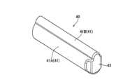
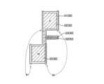
容器40は、筒状部分41と、底板部分42とを有する。筒状部分41は、香味発生物品10を収容するチャンバ40Cを形成する。筒状部分41は、熱伝導性部材によって構成される。熱伝導性部材は、特に限定されるものではないが、例えば、アルミニウムやステンレス(SUS)である。筒状部分41は、香味発生物品10を受け入れる第1端部40Xと、筒状部分41の長手方向(以下、長手方向A)において第1端部40Xの反対側に設けられる第2端部40Yとを有する。底板部分42は、第2端部40Yを塞ぐ。すな
わち、容器40は、筒状部分41及び底板部分42によって構成されるカップ形状を有する。容器40は、金属板の絞り加工などの手法によって一体成形されてもよい。The
容器40は、第1チャネル43と、第2チャネル44と、第3チャネル45とを有する。第1チャネル43は、空気流100Aの流路である。第1チャネル43は、長手方向Aに沿って延在する。第1チャネル43は、長手方向Aに交差する方向(以下、交差方向B)でチャンバ40Cに隣接する。第2チャネル44は、空気流100Bの流路である。第2チャネル44は、長手方向Aに沿って延在する。第2チャネル44は、チャンバ40C内を通る。第3チャネル45は、空気流100Cの流路である。第3チャネル45は、底板部分42側に設けられており、交差方向Bに沿って延在する。第1チャネル43は、第3チャネル45を介して第2チャネル44と連通する。
ここで、チャンバ40Cは、香味発生物品10を収容する空洞であり、香味発生物品10によって占有される部分であると考えてもよい。上述したように、第2チャネル44は、チャンバ40C内を通る流路であり、香味発生物品10内を通る流路であると考えてもよい。第2チャネル44は、チャンバ40Cと同義であると考えてもよく、チャンバ40Cの一部であると考えてもよい。 Here, the
ヒータ50は、筒状部分41の周面に配置され、チャンバ40Cに収容される香味発生物品を加熱する。ヒータ50は、筒状部分41の外周面に配置されてもよく、筒状部分41の内周面に配置されてもよい。ヒータ50は、筒状部分41の周面に接触していてもよい。図2では、ヒータ50が筒状部分41の外周面に配置されるケースを例示する。 The
ヒータ50は、基材51(基材51A及び基材51B)と、加熱要素52とを有する。加熱要素は、基材51Aと基材51Bとの間に挟まれる。基材51は、加熱要素を支持する。例えば、基材51は、ポリイミドなどのフィルムによって構成される。例えば、加熱要素52は、金属などの抵抗発熱体によって構成される。例えば、加熱要素52を構成する金属は、ニッケル合金、クロム合金、ステンレス及び白金ロジウムの中から選択された1以上の金属であってもよい。ヒータ50は、筒状部分41の周面に接着されてもよく、別個の支持部材によって筒状部分41の周面に支持されてもよい。図2において、ヒータ50の外側に不図示の熱収縮チューブを設置することによって、熱収縮チューブによってヒータ50が筒状部分41の外周面に取り付けられてもよい。 The
センサ60は、ヒータアッセンブリ30内で生じた温度変化の検出に用いられる。例えば、センサ60は、サーミスタや熱電対等の温度センサである。センサ60は、底板部分42に設けられてもよい。或いは、センサ60は、後述する第2部分41Bの内面又は外面に、第1チャネル43と隣接して設けられてもよい。センサ60は、第1チャネル43を空気が流れることによって生じる温度変化によってパフ動作を検出するために用いられてもよい。さらに、センサ60は、制御回路20による香味発生物品10の加熱制御に用いられてもよい。特に、制御回路20は、センサ60によって直接的又は間接的に測定したヒータアッセンブリ30又は吸引器120内の他の部分の温度が一定値を超過した場合に、加熱要素52への電力供給を停止するように構成されていてもよい。
(容器)
以下において、実施形態に係る容器について説明する。図3及び図4は、実施形態に係る容器40の斜視図である。図5は、実施形態に係る容器40を図3に示すP方向、Q方向及びR方向から見た図である。(container)
Below, the container which concerns on embodiment is demonstrated. 3 and 4 are perspective views of the
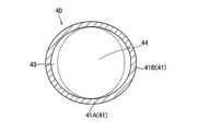
図3乃至図5に示すように、容器40の筒状部分41は、長手方向Aに対する直交断面において、チャンバ40Cを区画する第1部分41Aと、チャンバ40Cよりも外側に張
り出す第2部分41Bを含む。第2部分41Bは、長手方向Aに沿って延びるとともに第1チャネル43を形成する。すなわち、チャンバ40Cに香味発生物品110が収容された状態において、第1部分41Aは、香味発生物品110の外周面と接触し、第2部分41Bは、香味発生物品110の外周面から離間する。第1部分41A及び第2部分41Bは一体成形品であってもよい。As shown in FIGS. 3 to 5, the
ここで、長手方向Aに対する直交断面において、第1部分41Aは、香味発生物品110と略同様の形状を有していてもよい。例えば、香味発生物品110が円柱形状である場合に、第1部分41Aは略円筒形状を有していてもよい。長手方向Aに対する直交断面において、第2部分41Bは、チャンバ40Cよりも外側に張り出していればよく、例えば、円弧形状を有する。 Here, in a cross section orthogonal to the longitudinal direction A, the
図5に示すように、容器40は、括れ部分41Sを有する。括れ部分41Sは、香味発生物品110がチャンバ40Cに収容されたときに香味発生物品110に当接する当接部を構成する。括れ部分41Sは、筒状部分41の厚み自体は変わらずに、筒状部分41の内側に括れる部分であってもよい。 As shown in FIG. 5, the
(ヒータ)
以下において、実施形態に係るヒータについて説明する。図6及び図7は、実施形態に係るヒータ50を説明するための図である。上述したように、ヒータ50は、基材51及び加熱要素52を有する。(heater)
A heater according to the embodiment will be described below. 6 and 7 are diagrams for explaining the
図6に示すように、ヒータ50は、の加熱要素52に連続するリード線部分53を含む。例えば、リード線部分53は、制御回路20を介してバッテリ10に接続される。 As shown in FIG. 6,
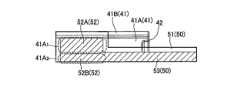
図6及び図7に示すように、ヒータ50は、容器40の筒状部分41に巻き回される。ここで、加熱要素52は、筒状部分41の周面における、第1チャネル43と隣接する部分以外の配置対象部分に沿って設けられる。実施形態では、加熱要素52は、第2部分41Bの周面に沿って設けられず、第1部分41Aの周面に沿って設けられる。すなわち、第1部分41Aの周面が配置対象部分を構成する。但し、基材51(基材51A及び基材51B)は、第2部分41Bの周面の一部又は全部に沿って設けられてもよいし、第2部分41Bの周面に沿って設けられなくてもよい。実施形態はこれに限定されるものではなく、加熱要素52は、第1部分41A及び第2部分41Bの双方の周面に沿って設けられてもよい。 As shown in FIGS. 6 and 7 , the
ここで、第1部分41Aの周面は、第1配置部分41A1と、第1配置部分41A1よりも第1チャネル43から離れた第2配置部分41A2とを含む。第1配置部分41A1における加熱要素52Aのワット密度は、第2配置部分41A2における加熱要素52Bのワ
ット密度よりも高くてもよい。Here, the peripheral surface of the
図6及び図7に示すように、加熱要素52は、第2端部40Yから離間するように、筒状部分41の周面に沿って設けられる。加熱要素52は、底板部分42に設けられることなく、筒状部分41の周面に沿って設けられる。 As shown in FIGS. 6 and 7, the
(作用及び効果)
実施形態では、チャンバ40Cを形成する筒状部分41の周面にヒータ50が配置されることを前提として、チャンバ40C内を通る第2チャネル44に連通する第1チャネル43がチャンバ40Cに隣接する。このような構成によれば、長手方向Aにおいてヒータアッセンブリ30の下方に連通するチャネルを設ける必要がなく、ヒータアッセンブリ30の底面を閉鎖する構造を採用することができる。従って、ヒータアッセンブリ30の下
方のデッドスペースを有効に利用することができる。さらには、第1チャネル43を通る空気が筒状部分41の周面に配置されるヒータ50によって予備的に加熱され得るため、チャンバ40Cに収容される香味発生物品110の温度低下が抑制され、香味発生物品110から効率的にエアロゾルを発生することができる効果も期待できる。(Action and effect)
In the embodiment, on the premise that the
実施形態では、筒状部分41の外周面にヒータ50が配置される。従って、ヒータ50のアッセンブリが容易である。 In the embodiment, a
実施形態では、加熱要素52は、筒状部分41の周面において、第1チャネル43と隣接する部分以外の配置対象部分(第1部分41Aの周面)に設けられる。このような構成によれば、第1チャネル43を流れる空気(空気流100A)が必要以上に加熱されることを抑制することができる。また、第1チャネル43と隣接する部分では香味発生物品110を直接的に加熱できないことに鑑みて、香味発生物品110の加熱に寄与しない部分に加熱要素52を配置しないことで、香味発生物品110の加熱に要するエネルギーを節約することができる。 In the embodiment, the
実施形態では、第1配置部分41A1における加熱要素52Aのワット密度は、第2配
置部分41A2における加熱要素52Bのワット密度よりも高くてもよい。このような構
成によれば、第1チャネル43と隣接する部分に加熱要素52が配置されないことに鑑み、第1チャネル43に隣接する位置において香味発生物品110の温度低下を抑制することができる。In embodiments, the watt density of the
実施形態では、容器40は、香味発生物品110がチャンバ40Cに収容されたときに香味発生物品110に当接する括れ部分41Sを有する。このような構成によれば、チャンバ40C内において香味発生物品110の位置決めが容易であり、第1チャネル43と第2チャネル44とを連通させる第3チャネル45を容易に確保することができる。 In an embodiment,
実施形態では、容器40は、筒状部分41の第2端部40Yを塞ぐ底板部分42を有しており、第3チャネル45が底板部分42側に設けられる。このような構成によれば、第1チャネル43から第2チャネル44への空気の流れ(空気流100C)を底板部分42によって生成することができる。 In an embodiment, the
実施形態では、容器40の筒状部分41は、長手方向Aに対する直交断面において、チャンバ40Cを区画する第1部分41Aと、チャンバ40Cよりも外側に張り出す第2部分41Bを含む。このような構成によれば、空気インレット、第1チャネル43及び第2チャネル44(チャンバ40C)を1つの部材(筒状部分41)によって実現することができ、ヒータアッセンブリ30の構造を簡素化することができる。 In the embodiment, the
実施形態では、チャンバ40Cに隣接するように第1チャネル43を配置することによって、長手方向Aにおいてヒータアッセンブリ30の下方に連通するチャネルを設ける必要がなく、ヒータアッセンブリ30の底面を閉鎖する構造を採用することができる。従って、ヒータアッセンブリ30の下方の空間をチャネル以外の用途で用いることができる。 In an embodiment, by locating the
実施形態では、センサ60は、底板部分42に設けられる。このような構成によれば、底板部分42が加熱要素52から離間しているため、加熱要素52から生じる熱の過度な影響をセンサ60が受けず、底板部分42がユーザの口腔から離れているため、外気から受ける過度な影響をセンサ60が受けない。従って、パフ動作の検知にセンサ60が用いられるケースなどにおいて、センサ60が温度変化を検出する精度を向上することができる。 In an embodiment,
(変更例1)
以下において、実施形態の変更例1について説明する。以下においては、実施形態に対する相違点について主として説明する。(Modification 1)
Modification 1 of the embodiment will be described below. In the following, mainly the differences with respect to the embodiments will be described.
実施形態において、第2部分41Bは、長手方向Aに対する直交断面において円弧形状を有する。これに対して、変更例1においては、図8に示すように、第2部分41Bは、長手方向Aに対する直交断面において、チャンバ40Cに向かって開口するU字形状を有する。詳細には、第2部分41Bは、円弧部分41B1及び1対の直線部分41B2を有する。図5~図7に示す例と同様に、ヒータ50の加熱要素52は、第2部分41Bの周面に沿って設けられず、第1部分41Aの周面に沿って設けられる。なお、ヒータ50の基材51(基材51A及び基材51B)は、第2部分41Bの1対の直線部分41B2に沿
って設けられてもよいし、さらに円弧部分41B1に沿って設けられてもよい。In the embodiment, the
但し、実施形態及び変更例1はこれに限定されるものではない。第2部分41Bは、長手方向Aに対する直交断面において、チャンバ40Cよりも外側に張り出していればよい。第2部分41Bは、矩形形状を有していてもよく、矩形及び円弧を組み合わせた形状を有していてもよい。 However, the embodiment and modification 1 are not limited to this. The
(変更例2)
以下において、実施形態の変更例2について説明する。以下においては、実施形態に対する相違点について主として説明する。(Modification 2)
Modification 2 of the embodiment will be described below. In the following, mainly the differences with respect to the embodiments will be described.
変更例2では、筒状部分41の形状のバリエーションについて説明する。変更例2においても、実施形態と同様に、筒状部分41は、長手方向Aに対する直交断面において、チャンバ40Cを区画する第1部分41Aと、チャンバ40Cよりも外側に張り出す第2部分41Bを含む。 In Modification 2, variations in the shape of the
例えば、図9に示すように、香味発生物品110の断面が円形である場合に、筒状部分41は、長手方向Aに対する直交断面において楕円形状を有していてもよい。このようなケースにおいて、筒状部分41の内周面と香味発生物品110の外周面との間に第1チャネル43が形成される。筒状部分41のうち、香味発生物品110の外周面と接触する部分が第1部分41Aを構成し、香味発生物品110の外周面から離間する部分が第2部分41Bを構成する。 For example, as shown in FIG. 9, when the cross section of the
例えば、図10に示すように、香味発生物品110の断面が円形である場合に、筒状部分41は、長手方向Aに対する直交断面において矩形形状を有していてもよい。このようなケースにおいて、筒状部分41の内周面と香味発生物品110の外周面との間に第1チャネル43が形成される。筒状部分41のうち、香味発生物品110の外周面と接触する部分が第1部分41Aを構成し、香味発生物品110の外周面から離間する部分が第2部分41Bを構成する。 For example, as shown in FIG. 10, when the cross section of the
(変更例3)
以下において、実施形態の変更例3について説明する。以下においては、実施形態に対する相違点について主として説明する。(Modification 3)
Modification 3 of the embodiment will be described below. In the following, mainly the differences with respect to the embodiments will be described.
変更例3において、容器40は、第1チャネル43を形成するチャネル形成部材を有する。チャネル形成部材は、筒状部分41の外周面に設けられる。 In variant 3, the
例えば、図11に示すように、容器40は、長手方向Aに対する直交断面において、円形形状を有するチャネル形成部材46を有していてもよい。言い換えると、チャネル形成
部材46は、長手方向Aに沿って延在する円筒形状を有してもよい。このようなケースにおいて、第1チャネル43は、チャネル形成部材46の内側に形成される。チャネル形成部材46は、筒状部分41の外周面に接着されてもよく、筒状部分41と一体で形成されてもよい。For example, as shown in FIG. 11, the
例えば、図12に示すように、容器40は、長手方向Aに対する直交断面において、筒状部分41を収容する楕円形状を有するチャネル形成部材46を有していてもよい。言い換えると、チャネル形成部材46は、長手方向Aに沿って延在する楕円の筒状形状を有してもよい。このようなケースにおいて、第1チャネル43は、チャネル形成部材46の内周面と筒状部分41の外周面との間に形成される。チャネル形成部材46は、筒状部分41の外周面に接着されてもよく、筒状部分41と一体で形成されてもよい。 For example, as shown in FIG. 12, the
(作用及び効果)
変更例3では、容器40は、第1チャネル43を形成するチャネル形成部材46を有する。このような構成によれば、第1チャネル43と第2チャネル44(チャンバ40C)とが少なくとも筒状部分41によって区画されるため、第1チャネル43から第2チャネル44への意図しない空気の流入を抑制することができる。意図しない空気の流入は、上述した第3チャネル45以外の流路を通る空気の流入である。(Action and effect)
In variant 3,
図12に示す例では、筒状部分41の周面に配置されるヒータ50は、第1チャネル43よりも内側に配置される。言い換えると、ヒータ50とチャンバ40Cとの間に第1チャネル43が介在しないため、図9に示すケースなどと比べると、ヒータ50から香味発生物品110にエネルギーを効率的に伝達することができる。 In the example shown in FIG. 12 , the
(変更例4)
以下において、実施形態の変更例4について説明する。以下においては、実施形態に対する相違点について主として説明する。(Modification 4)
Modification 4 of the embodiment will be described below. In the following, mainly the differences with respect to the embodiments will be described.
変更例4では、香味発生物品110がチャンバ40Cに収容されたときに香味発生物品110に当接する当接部のバリエーションについて説明する。 In Modification 4, a variation of the abutting portion that abuts on the
例えば、図13に示すように、容器40は、底面42から立設するリブ41Rを有する。なお、図13では、2つのリブ41Rが例示されているが、リブ41Rの数は任意である。 For example, as shown in FIG. 13, the
例えば、図14に示すように、容器40は、筒状部分41の内周面に設けられる段差部分47を当接部として有していてもよい。段差部分47は、筒状部分41の内周面からチャンバ40Cの内側に張り出す部分である。段差部分47は、底面42と接触していてもよく、底面42から離間していてもよい。段差部分47は、筒状部分41の内周面の全体に連続する部分であってもよく、筒状部分41の内周面において間欠的に設けられてもよい。段差部分47が間欠的に設けられる場合において、段差部分47の数は任意である。このようなケースにおいて、段差部分47は放熱部材によって構成されてもよい。 For example, as shown in FIG. 14, the
例えば、図15(A)に示すように、長手方向Aに対する直交断面において、チャンバ40Cを区画する第1部分41Aの内周面は、第2端部41Yに近づくに従って狭まっていてもよい。このようなケースにおいて、第1部分41Aの内周面のうち、香味発生物品110と接触する部分が当接部として機能する。ここで、第1部分41Aの内周面に加えて、第2部分41Bの内周面も、第2端部41Yに近づくに従って狭まっていてもよい。このような構成によれば、図15(B)に示すように、第1チャネル43から第3チャネル45に至るチャネルは、傾斜チャネル又は湾曲チャネルを含む。傾斜チャネル又は湾曲
チャネルは、第1チャネル43の一部であると考えてもよく、第3チャネル45の一部であると考えてもよい。傾斜チャネル又は湾曲チャネルを通る空気流100Dが生じるため、第1チャネル43から第2チャネル44に向けて空気がスムーズに流れる。For example, as shown in FIG. 15A, in a cross section perpendicular to the longitudinal direction A, the inner peripheral surface of the
例えば、図16に示すように、容器40の底面42は、チャンバ40Cの内側に張り出す形状を有しいてもよい。このようなケースにおいて、底面4のうち、香味発生物品110と接触する部分が当接部として機能する。このような底面42の形状は、上述したリブ41Rと同様の機能を果たす。 For example, as shown in FIG. 16, the
(変更例5)
以下において、実施形態の変更例5について説明する。以下においては、実施形態に対する相違点について主として説明する。(Modification 5)
Modification 5 of the embodiment will be described below. In the following, mainly the differences with respect to the embodiments will be described.
変更例5では、ヒータ50のバリエーションについて説明する。変更例5では、図17に示すように、容器40が2つの第1チャネル43を有するケースについて説明する。図17において、A1及びA2は、第1部分41Aの外周面を表す符号であり、B1及びB2は、2部分41Bの外周面を表す符号である。以下に示す図18~図20において、第1部分41Aの外周面に配置されるヒータ50の部分にA1及びA2の符号が付しており、2部分41Bの外周面に配置されるヒータ50の部分にB1及びB2の符号が付している。つまり、組立て後のヒータアッセンブリ30においては、図18中の符号A1,A2,B1,B2が付された領域が、図17中の同じ符号が付された領域と対向することになる。このことは図19及び図20に示す例についても同様である。 In Modification 5, variations of the
例えば、図18に示すように、ヒータ50の加熱要素52は、2つの加熱部分に分かれていてもよい。2つの加熱部分は、第1部分41Aの外周面に沿って配置され、他の部分は、2部分41Bの外周面に配置される。リード線53は、ヒータ50の一端に設けられてもよい。 For example, as shown in FIG. 18,
例えば、図19に示すように、ヒータ50の加熱要素52は、2つの加熱部分に分かれていてもよい。2つの加熱部分は、第1部分41Aの外周面に沿って配置され、他の部分は、2部分41Bの外周面に配置される。リード線53は、2つの加熱部分を接続する部分に設けられてもよい。 For example, as shown in FIG. 19,
例えば、図20に示すように、ヒータ50の加熱要素52は、2つの加熱部分に分かれていなくてもよい。ヒータ50は、2つの加熱部分は、第1部分41Aの外周面に沿って配置され、他の部分は、2部分41Bの外周面に配置される。リード線53は、2つの加熱部分を接続する部分に設けられてもよい。 For example, as shown in FIG. 20, the
(変更例6)
以下において、実施形態の変更例6について説明する。以下においては、実施形態に対する相違点について主として説明する。(Modification 6)
Modification 6 of the embodiment will be described below. In the following, mainly the differences with respect to the embodiments will be described.
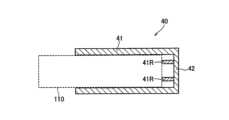
実施形態では、制御回路20は、バッテリ10とヒータアッセンブリ30との間に配置される。これに対して、変更例6では、制御回路20は、図21に示すように、ヒータアッセンブリ30の下方に設けられる。 In embodiments, the
変更例6では、実施形態と同様に、チャンバ40Cに隣接するように第1チャネル43を配置することによって、長手方向Aにおいてヒータアッセンブリ30の下方に連通するチャネルを設ける必要がなく、ヒータアッセンブリ30の底面を閉鎖する構造を採用することができる。従って、ヒータアッセンブリ30の下方に制御回路20を配置することが
でき、ヒータアッセンブリ30の下方のデッドスペースを有効に利用することができる。In Modification 6, as in the embodiment, by arranging the
[その他の実施形態]
本発明は上述した実施形態によって説明したが、この開示の一部をなす論述及び図面は、この発明を限定するものであると理解すべきではない。この開示から当業者には様々な代替実施形態、実施例及び運用技術が明らかとなろう。[Other embodiments]
Although the present invention has been described by the above-described embodiments, the statements and drawings forming part of this disclosure should not be construed as limiting the present invention. Various alternative embodiments, implementations and operational techniques will become apparent to those skilled in the art from this disclosure.
実施形態では、センサ60は底板部分42に設けられる。このようなケースにおいて、センサ60は、底板部分42の内面に設けられてもよく、底板部分42の外面に設けられてもよい。しかしながら、実施形態はこれに限定されるものではない。センサ60は、第1チャネル43に隣接する位置に設けられてもよい。このようなケースにおいて、センサ60は、第2部分41Bの外周面又は内周面に設けられてもよく、チャネル形成部材46の外周面又は内周面に設けられてもよい。このような構成によれば、センサ60が加熱要素52から離間するため、ヒータ50から生じる熱の過度な影響をセンサ60が受けず、従って、パフ動作の検知にセンサ60が用いられるケースなどにおいて、センサ60が温度変化を検出する精度を向上することができる。 In an embodiment,
実施形態では、容器40が1つの第1チャネル43を有するケースを例示した。しかしながら、実施形態はこれに限定されるものではない。容器40は、2以上の第1チャネル43を有してもよい。このようなケースにおいて、2以上の第1チャネル43は、筒状部分41の周面において均等に配置されてもよい。 The embodiment exemplifies the case where the
(追加変更例1)
以下において、実施形態の追加変更例1について説明する。追加変更例1において、例えば図2に示した容器40は、筒状部分41の内周面の少なくとも一部に形成された、筒状容器41の外周面よりも熱放射率の高い領域を有している。(Additional change example 1)
An additional modification example 1 of the embodiment will be described below. In addition modification example 1, for example, the
熱放射率の高い領域は、筒状部材41の内周面を黒色化することによって形成されてもよい。具体的には、筒状部材41の内周面にカーボン顔料を塗ったり、グラファイトフィルムを貼ったりして黒色層を設けてもよい。なお、黒色層を形成する材料は、特に限定されないが、カーボン、セラミック、シリコン、ガラス等の熱放射率および熱伝導率がともに高い材料を用いることが好ましい。 The high thermal emissivity region may be formed by blackening the inner peripheral surface of the
また、熱放射率の高い領域は、筒状部材41の内周面を黒色化することに限定されず、筒状部材41の内周面を酸化腐食させて粗くしたり、機械的に粗くしたり、筒状部材41の内周面に酸化膜を形成したりしてもよい。 In addition, the high thermal emissivity region is not limited to blackening the inner peripheral surface of the
これにより、筒状部分41の内周面の熱放射率を、筒状部分41の内周面を形成するアルミニウムやステンレス(SUS)と比べて大幅に高めることができる。そのため、熱放射による香味発生物品110の加熱を増強することができる。 As a result, the thermal emissivity of the inner peripheral surface of the
なお、熱放射率の高い領域は、筒状部材41の内周面全体に設けられてもよいし、例えば図3に示した第2部分41Bを除いて、第1部分41Aのみに設けられてもよい。 The region with high thermal emissivity may be provided on the entire inner peripheral surface of the
(追加変更例2)
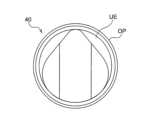
以下において、図22を参照して、実施形態の追加変更例2について説明する。追加変更例2において、例えば図22に示した第1部分41Aは、容器40内に香味発生物品が収容されたときに、当該物品を第1部分41Aと第2部分41Bの配列方向において少なくとも部分的に圧縮するように構成されることができる。第1部分41Aと第2部分41Bの配列方向を、以下では単に「配列方向」と称することがある。図23は、図22中の
容器40の開口OPを長手方向Aに見た上面図であり、図24は、図22中の点SCにおける容器40の横断面図である。図24に示した第1部分41Aの内周は、容器40内に香味発生物品が収容されたときに、当該物品を上記の配列方向(図24中の上下方向)において圧縮するように構成されることができる。特に、図24に示した第1部分41Aの内周は、喫煙物品の外周に接触可能な曲線部分41A3と、曲線部分41A3の両端部41A4,41A4から第2部分41Bの張り出し方向の頂部41B3に向かって延在する一対の直線部分41A5,41A5と、を有している。本例の曲線部分41A3は、上記の配列方向と交差する長軸を有する楕円の一部によって形成されることができる。(Additional change example 2)
An additional modification 2 of the embodiment will be described below with reference to FIG. 22 . In addition modification example 2, for example, the
図25は、図24中の容器40内に収容された略円柱形状の香味発生物品110を示す横断面図である。図25のように、香味発生物品110は、第1部分41Aの直線部分41A5,41A5及びそれらの近傍の曲線部分41A3によって径方向内向き(図中の斜め下向き)に押圧される。その結果、香味発生物品110の外面は、第1部分41Aの内面に密着することになる。容器40の第1部分41Aは、各種ヒータによって直接加熱されるので、その内面に香味発生物品110を密着させることで、香味発生物品110の加熱効率を向上させることができる。図25中の破線は、容器40内に収容されて圧縮される前の状態の香味発生物品110の外周を比較のために示している。 FIG. 25 is a cross-sectional view showing the substantially cylindrical flavor-generating
さらに、図25の例では、第1部分41Aの一対の直線部分41A5,41A5及びそれらの近傍の曲線部分41A3が、香味発生物品110の外面を図中の矢印の方向に(斜め下向きに)押圧するので、第2部分41Bの内部空間に香味発生物品110が入り込むのを抑制することができる。容器40が香味吸引器に組み込まれたときに、第2部分41Bの内部空間は、空気流路として機能する第1チャネル43(図2参照)を形成しうるので、そこに香味発生物品110が入り込むのを抑制することで、香味吸引器における空気流路の通気抵抗が増大するのを防止することができる。なお、本例の容器40は、香味発生物品を上述したように圧縮可能な横断面を、長手方向の全体にわたって有してもよいし、長手方向の一部のみに有してもよい。図25中の容器40は、その上下端部を除く長手方向の大部分において上述した横断面を有している。 Furthermore, in the example of FIG. 25, the pair of linear portions 41A5 and 41A5 of the
図22及び図23を参照すると、本例の容器40は、第1部分41Aと開口OPとの間に位置する中空の上縁部UEをさらに有している。図23の例では、容器40の開口OPは、香味発生物品110の外周と略同じか又はそれよりも幾分大きい内周を有しており、上縁部UEの内周は、開口OPから第1部分41Aに向かって徐々に小さくなっている。つまり、容器40の上縁部UEの内周面は、開口OPから挿入された香味発生物品を第1部分41Aに向かってガイドする役割を果たしている。 22 and 23, the
続いて、容器40の横断面形状の別の例について説明する。例えば図3に示した第1部分41Aは、長手方向の異なる位置において異なる横断面形状を有してもよい。それら異なる横断面形状が図26及び図27に例示されている。図26に示した第1部分41Aの内周は、円の一部によって形成されている。他方、図27に示した第1部分41Aの内周は、上記の配列方向と交差する長軸を有する楕円の一部によって形成されている。前述した図25の例とは異なり、図27に示した第1部分41Aの内周は一対の直線部分を有さないものの、図25の例と同じく、香味発生物品を上記の配列方向(図24中の上下方向)に圧縮することができる。容器40は、第1部分41Aの横断面が図26に示す形状から図27に示す形状へと連続的に変化するように構成されることができる。 Next, another example of the cross-sectional shape of the
なお、第1部分41Aの横断面の面積は、長手方向の位置によらず均一であってもよいし、長手方向の位置に応じて変化してもよい。例えば、第1部分41Aが長手方向の異なる位置で図26及び図27の横断面を有する場合、図27中の第1部分41Aの断面積は、図26中の第1部分41Aの断面積よりも小さくされることができる。ここでいう第1
部分41Aの断面積とは、第1部分41Aの内周と重なる仮想的な円又は楕円の面積を意味している。このように楕円で形成される第1部分41Aの断面積を相対的に小さくすることによって、香味発生物品を強く圧縮することができ、結果的に、香味発生物品の外周を第1部分41Aの内周に強く密着させることができる。一般的に、香味発生物品110は、先端側にたばこ原料を含むたばこ部が配置され、根元側にフィルタを含む紙管部が配置される。ここで、たばこ部は外部から働く力によって変形しやすいが、紙管部は変形しにくい。そこで、たばこ部に対して図27のような楕円形の内周を配置し、紙管部に対して図26のような円形の内周を配置させることが好ましい。The cross-sectional area of the
The cross-sectional area of the
(追加変更例3)
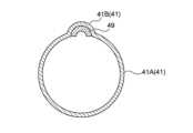
以下において、実施形態の追加変更例3について説明する。追加変更例3において、第2部分41Bによって形成された第1チャネル43は、ヒータアッセンブリ及びそれが組み込まれた香味吸引器の外部から、第1部分41Aによって形成された第2チャネル44に向かう空気流路を形成することができる(図2及び図3等を参照)。そして、本例のヒータアッセンブリ及びそれが組み込まれた香味吸引器は、第1チャネル43の逆方向の流体流れを阻害する阻害部材を備えることができる。例えば図3に示したヒータアッセンブリの容器40は、上記の阻害部材として、第2部分41Bに形成された、第1チャネルの一部を塞ぐ隔壁49を備えることができる。(Additional change example 3)
An additional modification example 3 of the embodiment will be described below. In additional modification 3, the
図28および図29は、追加変更例3に係る隔壁49を説明するための図である。図28および図29において、隔壁49は、プラスチック製、ゴム製等の板状部材である。また、隔壁49は、第2部分41Bの長手方向に沿って1箇所に設けられてもよいし、複数箇所に設けられてもよい。また、隔壁49は、図30に示すように、底板部分42に向けて、取り付け位置から傾斜して設けられてもよい。 28 and 29 are diagrams for explaining the
なお、隔壁49は、第1チャネル43において、第1端部40Xから第2端部40Yに向かう順方向の空気の流れを許容しつつ、第2端部40Yから第1端部40Xに向かう逆方向の熱蒸気流を阻害する形状を有していれば、どのような形状であってもよい。 It should be noted that the
これにより、第2端部40Yから第1端部40Xに向けて熱蒸気が逆流してきた場合に、熱蒸気流が隔壁49に衝突して減速し、凝縮が促されることで、熱蒸気の温度を低下させることができる。 As a result, when the hot steam flows back from the
なお、少なくとも1つの隔壁49は、第1端部40Xの近傍に設けられることが好ましい。また、隔壁49は、図11に示したチャネル形成部材46に設けられもよい。 At least one
続いて、阻害部材の別の例について説明する。ヒータアッセンブリ及びそれが組み込まれた香味吸引器は、容器40から離間した位置に阻害部材を有していてもよい。図31は、本例の阻害部材を備えた香味吸引器100を示す図である。図31中の香味吸引器100には、ヒータアッセンブリ30の一部として図31中の容器40が組み込まれている。図31中の香味吸引器100は、容器40の開口OPを覆うための可動式の蓋部材LDを備えている。蓋部材LDは、香味吸引器100の非使用時に容器40の開口OPを覆う閉位置(第2位置)と、香味吸引器100の使用時に容器40の開口OPを少なくとも部分的に露出させる開位置(第1位置)と、の間で移動可能である。図31中の蓋部材LDは、閉位置に在る。 Next, another example of the blocking member will be described. The heater assembly and the flavor inhaler in which it is incorporated may have an obstruction member spaced from the
図32は、蓋部材LDが開位置に在るときの香味吸引器100を示す図である。蓋部材LDが開位置に在るときに、使用者は、香味発生物品110を開口OPから容器40内に挿入することができる。本例では、開位置に在る蓋部材LDに上記の阻害部材の機能を持たせることができる。具体的には、蓋部材LDを、それが開位置に在るときにも容器40
の開口OPの一部を覆うように構成することによって、蓋部材LDに阻害部材の機能を持たせることができる。このようにして構成された蓋部材LDは、図28及び図29等に示した隔壁49と同じく、第1チャネル43の順方向の空気流を許容しつつ、逆方向の熱蒸気流を阻害することができる。香味吸引器100は、蓋部材LDと隔壁49の両方を備えていてもよい。FIG. 32 shows the
By configuring the cover member LD to cover a part of the opening OP, the lid member LD can be given the function of the blocking member. Like the
また、前述した阻害部材に代えて、例えば図3に示した第2部分41Bに、第1チャネルにおける空気の逆流を妨げる逆流防止機構が設けられてもよい。逆流防止機構は、隔壁49が設けられる箇所と同じ箇所に、第1チャネルの全体を塞ぐように設けられてもよい。また、逆流防止機構は、例えば柔軟な材料によって形成され、第1端部40Xから第2端部40Yに向かう順方向の空気の流れを通すとともに、第2端部40Yから第1端部40Xに向かう逆方向の熱蒸気流を遮断する。また、逆流防止機構が、図11に示したチャネル形成部材46に設けられる場合には、公知の逆止弁を用いてもよい。 Further, instead of the blocking member described above, for example, a backflow prevention mechanism that prevents backflow of air in the first channel may be provided in the
(追加変更例4)
以下において、実施形態の追加変更例4について説明する。追加変更例4において、例えば図2に示した容器40の筒状部材41および底板部分42は、断熱部材70によって覆われている。(Additional change example 4)
An additional modification example 4 of the embodiment will be described below. In Modification 4, for example, the
図33は、追加変更例4に係る断熱部材70を説明するための図である。図33において、断熱部材70は、筒状部材41を覆う第1断熱部材71と、底板部分42を覆う第2断熱部材72とを有していてもよい。第1断熱部材71および第2断熱部材72は、真空断熱材や、エアロゲル、シリコン等を断熱材料とする断熱部材である。 FIG. 33 is a diagram for explaining the
また、断熱部材70は、筒状部材41を覆う第1断熱部材71と、底板部分42を覆う第2断熱部材72とが継ぎ目なく連続した一体の断熱部材であってもよい。例えば、断熱部材70は、筒状部材41および底板部分42を覆う真空断熱容器のような断熱部材であってもよい。 Alternatively, the
これにより、容器40の底板部分42が断熱部材70によって覆われているので、容器40の底面から回り込んで制御回路20やバッテリ10に熱が到達することを防止することができる。 As a result, since the
また、断熱部材70が第1断熱部材71および第2断熱部材72から構成される場合には、筒状部材41の外周面に配置されたヒータ50のリード線部分53を、第1断熱部材71と第2断熱部材72との間に通すことができる。 Further, when the
なお、第1断熱部材71および第2断熱部材72は、同一の熱伝導率を有する材料からなる断熱部材であってもよいし、互いに異なる熱伝導率を有する材料からなる断熱部材であってもよい。すなわち、第1断熱部材71と第2断熱部材72との断熱性能は、同じであってもよいし、一方がより高い断熱性能を有していてもよい。筒状部材41の外周面にヒータ50が配置される態様では、第1断熱部材71の断熱性能を強化することが好ましい。そのため、第2断熱部材72の断熱性能は、第1断熱部材71の断熱性能より低くてもよい。 The first
(追加変更例5)
以下において、実施形態の追加変更例5について説明する。追加変更例5において、例えば図2に示したヒータ50およびセンサ60は、図示しない熱収縮チューブによって覆われている。(Additional change example 5)
An additional modification example 5 of the embodiment will be described below. In addition modification 5, the
すなわち、上述した実施形態では、ヒータ50の外側のみに熱収縮チューブが設置されていたところ、追加変更例5では、容器40の筒状部材41および底板部分42を覆うように熱収縮チューブが設置される。 That is, in the above-described embodiment, the heat-shrinkable tube is installed only on the outside of the
これにより、パフ動作を検出するセンサ60が容器40の底板部分42に設けられる場合に、ヒータ50とセンサ60とを一緒に固定することができる。 This allows the
(追加変更例6)
以下において、実施形態の追加変更例6について説明する。追加変更例6において、例えば図2に示した筒状部材41とヒータ50との間には、筒状部材41よりも熱伝導率の高い膜が設けられている。(Additional change example 6)
In the following, an additional modification example 6 of the embodiment will be described. In Modification 6, a film having a higher thermal conductivity than the
熱伝導率の高い材料からなる膜は、筒状部分41を形成するアルミニウムやステンレス(SUS)よりも高い熱伝導率を有する銅やその他の金属からなる膜である。 The film made of a material with high thermal conductivity is a film made of copper or other metals having higher thermal conductivity than aluminum or stainless steel (SUS) forming the
これにより、ヒータ50のパターン部分で発生した熱を、熱伝導率の高い材料からなる膜で均等化することができ、香味発生物品110の外面を均等に加熱することができる。そのため、香味発生物品110に含まれる香味を発生しうる成分の消費が均等化されるとともに、喫味も均一化される。さらに、香味発生物品110が局所的に加熱されることが防止され、その箇所だけエアロゾル源が枯渇することも防止される。 Thereby, the heat generated in the pattern portion of the
(追加変更例7)
以下において、実施形態の追加変更例7について説明する。追加変更例7において、例えば図2に示した容器40は、底板部分42に設けられ、香味発生物品110がチャンバ40Cに収容されたときに香味発生物品110の先端部に当接する台座80を有している。(Additional change example 7)
An additional modification example 7 of the embodiment will be described below. In addition modification example 7, the
図34は、追加変更例7に係る台座80を説明するための図である。図34において、台座80は、第2部分41Bと同心円状に形成された円柱形状を有していてもよい。また、台座80は、台座80の周りに、第1チャネル43および第2チャネル44と連通する環状の隙間を形成する。すなわち、この環状の隙間は、空気流100Cの流路である第3チャネル45に相当する。 FIG. 34 is a diagram for explaining a
これにより、第1チャネル43を流れる空気が、台座80によって形成された環状の隙間で旋回し、香味発生物品110の先端部に当接する台座80を除く部分から、香味発生物品110に均一に流入する。そのため、香味発生物品110に含まれる基材の消費が均等化されるとともに、喫味も均一化される。 As a result, the air flowing through the
Claims (20)
Translated fromJapanese底板部分と、
前記底板部分に設けられ、パフ動作による温度変化を検出するように構成される温度センサと、
前記容器に前記香味発生物品が収容されたときに前記香味発生物品の外周面を押圧する第1部分を含む筒状部分と、を有し、
前記香味発生物品を収容しているとき、前記香味発生物品の外周面の少なくとも一部と前記容器の前記筒状部分の内周面の少なくとも一部との間に第1チャネルが形成され、
前記香味発生物品を収容しているとき、前記香味発生物品の先端部と前記底板部分との間に第3チャネルが形成され、
前記第1チャネルは、前記第3チャネルを介して前記香味発生物品内を通る第2チャネルと連通して、前記第2チャネルには、前記第1チャネルを通過した空気のみが供給され、
前記底板部分は、前記筒状部分の端部を塞ぐように構成される、容器。A container used for an inhaler and containing a flavor-generating article,
a bottom plate and
a temperature sensor provided on the bottom plate portion and configured to detect a temperature change due to the puffing action;
a cylindrical portion including a first portion that presses against the outer peripheral surface of the flavor generating article when the flavor generating article is accommodated in the container;
forming a first channel between at least a portion of an outer peripheral surface of the flavor generating article and at least a portion of an innerperipheral surface of the tubular portion of the container when the flavor generating article is contained;
forming a third channel between the top portion of the flavor generating article and the bottom plate portion when the flavor generating article is contained;
the first channelcommunicates with a second channel passing through the flavor-generating article via the third channel, and the second channel is supplied only with air that has passed through the first channel;
The container, wherein the bottom plate portion is configured to close an end of the tubular portion .
前記筒状部分は、長手方向に対する直交断面において前記第1部分と第2部分とを有し、
前記第2部分は、前記容器に前記香味発生物品が収容されたときに前記香味発生物品の外周面から離間する、容器。A container according to claim 1,
The cylindrical portion has the first portion and the second portion in a cross section perpendicular to the longitudinal direction,
The container, wherein the second portion is separated from the outer peripheral surface of the flavor generating article when the flavor generating article is accommodated in the container.
前記温度センサは、前記底板部分の内面又は外面に設けられる、容器。In the container according to claim 1 or 2,
The container, wherein the temperature sensor is provided on the inner surface or the outer surface of the bottom plate portion.
前記温度センサは、前記第1チャネルを空気が流れることによって生じる温度変化によってパフ動作を検出するように構成される、容器。In the container according to any one of claims 1 to 3,
The container, wherein the temperature sensor is configured to detect puffing by temperature changes caused by air flowing through the first channel.
前記温度センサは、前記容器を含むヒータアッセンブリ内で生じた温度変化の検出に用いられる、容器。In the container according to any one of claims 1 to 4,
A container, wherein the temperature sensor is used to detect temperature changes occurring within a heater assembly that contains the container.
前記温度センサは、制御回路による前記香味発生物品の加熱制御に用いられる、容器。A container according to any one of claims 1 to 5,
The container, wherein the temperature sensor is used for heating control of the flavor generating article by a control circuit.
前記制御回路は、前記温度センサによって測定した吸引器内の温度が一定値を超過した場合に電力供給を停止するように構成される、容器。A container according to claim 6,
The container, wherein the control circuit is configured to stop the power supply if the temperature in the suction device as measured by the temperature sensor exceeds a certain value.
前記温度センサは、熱収縮チューブによって覆われる、容器。A container according to any one of claims 1 to 7,
The container, wherein the temperature sensor is covered by a heat shrink tube.
前記容器は、底板部分と、前記底板部分に設けられ、パフ動作による温度変化を検出するように構成される温度センサと、前記容器に前記香味発生物品が収容されたときに前記香味発生物品の外周面を押圧する第1部分を含む筒状部分と、を有し、
前記容器が前記香味発生物品を収容しているとき、前記香味発生物品の外周面の少なくとも一部と前記容器の前記筒状部分の内周面の少なくとも一部との間に第1チャネルが形成され、
前記容器が前記香味発生物品を収容しているとき、前記香味発生物品の先端部と前記底板部分との間に第3チャネルが形成され、
前記第1チャネルは、前記第3チャネルを介して前記香味発生物品内を通る第2チャネルと連通して、前記第2チャネルには、前記第1チャネルを通過した空気のみが供給され、
前記底板部分は、前記筒状部分の端部を塞ぐように構成される、吸引器システム。An inhaler system comprising: an inhaler comprising a container for containing a flavor generating article; and the flavor generating article,
The container comprises a bottom plate portion, a temperature sensor provided on the bottom plate portion and configured to detect a temperature change due to a puffing action, and a temperature sensor that detects the temperature of the flavor generating article when the flavor generating article is accommodated in the container. a cylindrical portion including a first portion that presses the outer peripheral surface;
When the container contains the flavor generating article, a first channel is formed between at least a portion of the outer peripheral surface of the flavor generating article and at least a portion ofthe inner peripheral surface of the tubular portion of the container. is,
forming a third channel between the top portion of the flavor generating article and the bottom plate portion when the container contains the flavor generating article;
the first channelcommunicates with a second channel passing through the flavor-generating article via the third channel, and the second channel is supplied only with air that has passed through the first channel;
The aspirator system, wherein the bottom plate portion is configured to close an end of the tubular portion .
前記筒状部分は、長手方向に対する直交断面において前記第1部分と第2部分とを有し、
前記第2部分は、前記容器に前記香味発生物品が収容されたときに前記香味発生物品の外周面から離間する、吸引器システム。An aspirator system according to claim 9, wherein
The cylindrical portion has the first portion and the second portion in a cross section perpendicular to the longitudinal direction,
The inhaler system, wherein the second portion is spaced apart from the outer peripheral surface of the flavor generating article when the flavor generating article is contained in the container.
前記温度センサは、前記底板部分の内面又は外面に設けられる、吸引器システム。An aspirator system according to any one of claims 9-10,
The aspirator system, wherein the temperature sensor is provided on the inner or outer surface of the bottom plate portion.
前記温度センサは、前記第1チャネルを空気が流れることによって生じる温度変化によってパフ動作を検出するように構成される、吸引器システム。An aspirator system according to any one of claims 9 to 11, wherein
The aspirator system, wherein the temperature sensor is configured to detect puffing by temperature changes caused by air flowing through the first channel.
前記吸引器は、前記容器を含むヒータアッセンブリを有し、
前記温度センサは、前記ヒータアッセンブリ内で生じた温度変化の検出に用いられる、吸引器システム。An aspirator system according to any one of claims 9 to 12, wherein
the aspirator having a heater assembly containing the container;
The aspirator system, wherein the temperature sensor is used to detect temperature changes occurring within the heater assembly.
前記吸引器は、制御回路を有し、
前記温度センサは、前記制御回路による前記香味発生物品の加熱制御に用いられる、吸引器システム。An aspirator system according to any one of claims 9 to 13, wherein
The aspirator has a control circuit,
The inhaler system, wherein the temperature sensor is used to control heating of the flavor generating article by the control circuit.
前記制御回路は、前記温度センサによって測定した吸引器内の温度が一定値を超過した場合に電力供給を停止するように構成される、吸引器システム。15. The aspirator system of claim 14, wherein
The aspirator system, wherein the control circuit is configured to stop power supply if the temperature in the aspirator as measured by the temperature sensor exceeds a certain value.
前記温度センサは、熱収縮チューブによって覆われる、吸引器システム。An aspirator system according to any one of claims 9 to 15, wherein
The aspirator system, wherein the temperature sensor is covered by heat shrink tubing.
前記容器を含むヒータアッセンブリと、
制御回路と、を有する吸引器システム。An aspirator system according to claim 9, wherein
a heater assembly including the container;
and a control circuit.
前記香味発生物品の加熱を開始するための押しボタンを有する、吸引器システム。18. The aspirator system of claim 17, wherein
An inhaler system having a push button for initiating heating of the flavor generating article.
前記制御回路は、パフ動作の回数が一定値を超過したとき、前記香味発生物品の加熱を終了するように前記ヒータアッセンブリを制御する、吸引器システム。18. The aspirator system of claim 17, wherein
The inhaler system, wherein the control circuit controls the heater assembly to terminate heating of the flavor generating article when the number of puffs exceeds a certain value.
前記制御回路は、加熱を開始して一定時間が経過したとき、前記香味発生物品の加熱を終了するように前記ヒータアッセンブリを制御する、吸引器システム。18. The aspirator system of claim 17, wherein
The inhaler system, wherein the control circuit controls the heater assembly to stop heating the flavor-generating article after a certain period of time has elapsed since heating was started.
Applications Claiming Priority (3)
| Application Number | Priority Date | Filing Date | Title |
|---|---|---|---|
| JP2018085336 | 2018-04-26 | ||
| JP2018085336 | 2018-04-26 | ||
| JP2021192733AJP7469283B2 (en) | 2018-04-26 | 2021-11-29 | Heater Assembly and Container |
Related Parent Applications (1)
| Application Number | Title | Priority Date | Filing Date |
|---|---|---|---|
| JP2021192733ADivisionJP7469283B2 (en) | 2018-04-26 | 2021-11-29 | Heater Assembly and Container |
Publications (2)
| Publication Number | Publication Date |
|---|---|
| JP2023012469A JP2023012469A (en) | 2023-01-25 |
| JP7273232B2true JP7273232B2 (en) | 2023-05-12 |
Family
ID=68294097
Family Applications (11)
| Application Number | Title | Priority Date | Filing Date |
|---|---|---|---|
| JP2020515467APendingJPWO2019208536A1 (en) | 2018-04-26 | 2019-04-23 | Heater assembly and container |
| JP2021192720APendingJP2022033838A (en) | 2018-04-26 | 2021-11-29 | Heater assembly and container |
| JP2021192689AActiveJP7043674B2 (en) | 2018-04-26 | 2021-11-29 | Heater assembly and container |
| JP2021192706AActiveJP7030238B2 (en) | 2018-04-26 | 2021-11-29 | Heater assembly and container |
| JP2021192682AActiveJP7030237B2 (en) | 2018-04-26 | 2021-11-29 | Heater assembly and container |
| JP2021192733AActiveJP7469283B2 (en) | 2018-04-26 | 2021-11-29 | Heater Assembly and Container |
| JP2022122462AActiveJP7158621B2 (en) | 2018-04-26 | 2022-08-01 | heater assembly and container |
| JP2022162899AActiveJP7273232B2 (en) | 2018-04-26 | 2022-10-11 | heater assembly and container |
| JP2023025234AActiveJP7279271B2 (en) | 2018-04-26 | 2023-02-21 | heater assembly and container |
| JP2024060749AActiveJP7676620B2 (en) | 2018-04-26 | 2024-04-04 | Heater Assembly and Container |
| JP2025075135APendingJP2025111724A (en) | 2018-04-26 | 2025-04-30 | Heater assembly and container |
Family Applications Before (7)
| Application Number | Title | Priority Date | Filing Date |
|---|---|---|---|
| JP2020515467APendingJPWO2019208536A1 (en) | 2018-04-26 | 2019-04-23 | Heater assembly and container |
| JP2021192720APendingJP2022033838A (en) | 2018-04-26 | 2021-11-29 | Heater assembly and container |
| JP2021192689AActiveJP7043674B2 (en) | 2018-04-26 | 2021-11-29 | Heater assembly and container |
| JP2021192706AActiveJP7030238B2 (en) | 2018-04-26 | 2021-11-29 | Heater assembly and container |
| JP2021192682AActiveJP7030237B2 (en) | 2018-04-26 | 2021-11-29 | Heater assembly and container |
| JP2021192733AActiveJP7469283B2 (en) | 2018-04-26 | 2021-11-29 | Heater Assembly and Container |
| JP2022122462AActiveJP7158621B2 (en) | 2018-04-26 | 2022-08-01 | heater assembly and container |
Family Applications After (3)
| Application Number | Title | Priority Date | Filing Date |
|---|---|---|---|
| JP2023025234AActiveJP7279271B2 (en) | 2018-04-26 | 2023-02-21 | heater assembly and container |
| JP2024060749AActiveJP7676620B2 (en) | 2018-04-26 | 2024-04-04 | Heater Assembly and Container |
| JP2025075135APendingJP2025111724A (en) | 2018-04-26 | 2025-04-30 | Heater assembly and container |
Country Status (11)
| Country | Link |
|---|---|
| US (4) | US11696601B2 (en) |
| EP (3) | EP4447613A3 (en) |
| JP (11) | JPWO2019208536A1 (en) |
| KR (4) | KR102586323B1 (en) |
| CN (2) | CN118766158A (en) |
| ES (1) | ES2965687T3 (en) |
| HU (1) | HUE064346T2 (en) |
| PL (1) | PL4133959T3 (en) |
| PT (1) | PT4133959T (en) |
| TW (6) | TWI816196B (en) |
| WO (1) | WO2019208536A1 (en) |
Families Citing this family (38)
| Publication number | Priority date | Publication date | Assignee | Title |
|---|---|---|---|---|
| KR102586323B1 (en) | 2018-04-26 | 2023-10-10 | 니뽄 다바코 산교 가부시키가이샤 | Heater assembly and container |
| GB201816831D0 (en) | 2018-10-16 | 2018-11-28 | Nicoventures Trading Ltd | Aerosol provision device |
| KR102793114B1 (en)* | 2020-02-27 | 2025-04-09 | 니뽄 다바코 산교 가부시키가이샤 | Smoking Systems, Devices, and Consumables |
| EP4110111A1 (en)* | 2020-02-28 | 2023-01-04 | JT International SA | Aerosol generation device |
| CN115038347A (en)* | 2020-03-18 | 2022-09-09 | 日本烟草产业株式会社 | Suction device, information processing method and program |
| CN111420620B (en)* | 2020-04-21 | 2025-06-17 | 深圳麦时科技有限公司 | Aerosol Generating Device |
| EP4248772A3 (en)* | 2020-04-23 | 2024-01-17 | Japan Tobacco Inc. | Heating unit for flavor inhaler and flavor inhaler |
| EP4074200A4 (en)* | 2020-04-28 | 2023-09-13 | Japan Tobacco Inc. | Inhalation device, control method, and program |
| EP3930511B1 (en) | 2020-05-07 | 2024-05-01 | KT&G Corporation | Apparatus for generating aerosol comprising multilayer thermally conductive member |
| CN213587421U (en)* | 2020-08-13 | 2021-07-02 | 深圳市合元科技有限公司 | Aerosol generator |
| KR102567136B1 (en)* | 2020-09-01 | 2023-08-18 | 주식회사 케이티앤지 | Aerosol-generating apparatus with improved heating efficiency |
| GB202016480D0 (en)* | 2020-10-16 | 2020-12-02 | Nicoventures Trading Ltd | Aerosol provision device |
| KR102637742B1 (en)* | 2020-11-25 | 2024-02-19 | 주식회사 케이티앤지 | Aerosol generating device |
| WO2022123769A1 (en)* | 2020-12-11 | 2022-06-16 | 日本たばこ産業株式会社 | Flavor inhaler |
| KR20230111232A (en)* | 2020-12-11 | 2023-07-25 | 니뽄 다바코 산교 가부시키가이샤 | flavor inhaler |
| PL4260722T3 (en)* | 2020-12-11 | 2025-07-14 | Japan Tobacco Inc. | Inhaler |
| KR20230132500A (en)* | 2021-02-12 | 2023-09-15 | 니뽄 다바코 산교 가부시키가이샤 | Non-combustible heated tobacco products and non-combustible heated tobacco sticks |
| CN215347056U (en)* | 2021-03-19 | 2021-12-31 | 深圳市合元科技有限公司 | Heating mechanism and aerosol-generating device |
| EP4321042A4 (en)* | 2021-04-09 | 2025-01-29 | Japan Tobacco Inc. | FLAVOR INHALER AND SMOKING SYSTEM |
| KR20230169225A (en)* | 2021-04-26 | 2023-12-15 | 니뽄 다바코 산교 가부시키가이샤 | flavor aspirator |
| KR20230172557A (en)* | 2021-04-28 | 2023-12-22 | 니뽄 다바코 산교 가부시키가이샤 | Flavor aspirator and smoking system |
| JP7467770B2 (en)* | 2021-05-10 | 2024-04-15 | 日本たばこ産業株式会社 | Aerosol generator power supply unit |
| EP4305984A4 (en)* | 2021-06-16 | 2025-01-22 | Japan Tobacco Inc. | AEROSOL GENERATING SYSTEM |
| CN113729287A (en)* | 2021-09-08 | 2021-12-03 | 深圳麦克韦尔科技有限公司 | Guide member, heating unit, and aerosol generating device |
| CN113729286A (en)* | 2021-09-08 | 2021-12-03 | 深圳麦克韦尔科技有限公司 | Heating assembly and aerosol generating device |
| KR20240095443A (en)* | 2021-10-29 | 2024-06-25 | 니뽄 다바코 산교 가부시키가이샤 | Suction device, substrate, and method of controlling the suction device |
| CN113925208B (en)* | 2021-11-25 | 2024-01-16 | 深圳市汉清达科技有限公司 | A heating device for electronic cigarettes |
| JP7746408B2 (en)* | 2021-12-06 | 2025-09-30 | 日本たばこ産業株式会社 | Aerosol Generation System |
| WO2023105559A1 (en)* | 2021-12-06 | 2023-06-15 | 日本たばこ産業株式会社 | Aerosol generating system |
| KR20240043159A (en)* | 2021-12-06 | 2024-04-02 | 니뽄 다바코 산교 가부시키가이샤 | aerosol generation system |
| WO2023112143A1 (en)* | 2021-12-14 | 2023-06-22 | 日本たばこ産業株式会社 | Atomization unit and flavor inhaler |
| WO2023112145A1 (en)* | 2021-12-14 | 2023-06-22 | 日本たばこ産業株式会社 | Atomization unit and flavor inhaler |
| GB202118879D0 (en)* | 2021-12-23 | 2022-02-09 | Nicoventures Trading Ltd | Aerosol provision device |
| WO2023218586A1 (en)* | 2022-05-12 | 2023-11-16 | 日本たばこ産業株式会社 | Aerosol generating system and method for producing aerosol generating system |
| JPWO2024171240A1 (en)* | 2023-02-13 | 2024-08-22 | ||
| JP7633579B2 (en) | 2023-03-31 | 2025-02-20 | ダイキン工業株式会社 | Centrifugal Compressor |
| WO2024223831A1 (en)* | 2023-04-28 | 2024-10-31 | Jt International Sa | Tobacco article for a heat-not-burn aerosol generating device and associated aerosol generating system |
| WO2024223829A1 (en)* | 2023-04-28 | 2024-10-31 | Jt International Sa | Tobacco article for a heat-not-burn aerosol generating device and associated aerosol generating system |
Citations (8)
| Publication number | Priority date | Publication date | Assignee | Title |
|---|---|---|---|---|
| JP2009509523A (en) | 2005-09-30 | 2009-03-12 | フィリップ・モーリス・プロダクツ・ソシエテ・アノニム | Electric smoking system |
| JP2013511962A (en) | 2009-11-27 | 2013-04-11 | フィリップ・モーリス・プロダクツ・ソシエテ・アノニム | Electric heating smoking system with internal or external heater |
| JP2015503916A (en) | 2011-12-30 | 2015-02-05 | フィリップ・モーリス・プロダクツ・ソシエテ・アノニム | Aerosol generator with airflow detection |
| JP2015504667A (en) | 2012-01-03 | 2015-02-16 | フィリップ・モーリス・プロダクツ・ソシエテ・アノニム | Aerosol generator and system with improved airflow |
| JP2015506170A (en) | 2011-12-30 | 2015-03-02 | フィリップ・モーリス・プロダクツ・ソシエテ・アノニム | Aerosol generator with improved temperature distribution |
| WO2016150922A2 (en) | 2015-03-26 | 2016-09-29 | Philip Morris Products S.A. | Heater management |
| WO2016207407A1 (en) | 2015-06-26 | 2016-12-29 | British American Tobacco (Investments) Limited | Apparatus for heating smokable material |
| WO2018002083A1 (en) | 2016-06-29 | 2018-01-04 | British American Tobacco (Investments) Limited | Apparatus for heating smokable material |
Family Cites Families (46)
| Publication number | Priority date | Publication date | Assignee | Title |
|---|---|---|---|---|
| JPS6032690Y2 (en) | 1982-10-19 | 1985-09-30 | 株式会社学習研究社 | Electric circuit connection teaching experiment equipment |
| US4819665A (en)* | 1987-01-23 | 1989-04-11 | R. J. Reynolds Tobacco Company | Aerosol delivery article |
| ATE121909T1 (en) | 1991-03-11 | 1995-05-15 | Philip Morris Prod | FLAVOR PRODUCING ITEMS. |
| US5665262A (en) | 1991-03-11 | 1997-09-09 | Philip Morris Incorporated | Tubular heater for use in an electrical smoking article |
| JP2796219B2 (en) | 1992-08-03 | 1998-09-10 | シャープ株式会社 | Cooking device |
| US5954979A (en)* | 1997-10-16 | 1999-09-21 | Philip Morris Incorporated | Heater fixture of an electrical smoking system |
| WO2000005976A1 (en)* | 1998-07-30 | 2000-02-10 | Burruss Robert P | Air heater for a non-combustion vaporizing device |
| JP2011087569A (en) | 2009-05-15 | 2011-05-06 | Jbs:Kk | Electronic cigarette and charging unit |
| EP2316286A1 (en) | 2009-10-29 | 2011-05-04 | Philip Morris Products S.A. | An electrically heated smoking system with improved heater |
| KR101389143B1 (en)* | 2010-08-24 | 2014-04-24 | 니뽄 다바코 산교 가부시키가이샤 | Non-heating type apparatus for inhaling flavors and method for manufacturing flavor cartridge |
| CN103826481B (en)* | 2011-09-06 | 2016-08-17 | 英美烟草(投资)有限公司 | Heating smokeable material |
| AR089602A1 (en)* | 2011-12-30 | 2014-09-03 | Philip Morris Products Sa | AEROSOL GENERATOR ARTICLE FOR USE WITH AN AEROSOL GENERATOR DEVICE |
| MY170381A (en)* | 2011-12-30 | 2019-07-27 | Philip Morris Products Sa | Smoking article with front-plug and aerosol-forming substrate and method |
| BR112014016425B1 (en) | 2012-01-03 | 2020-12-15 | Philip Morris Products S.A | AEROSOL GENERATION SYSTEM |
| EP3222159B1 (en) | 2013-09-30 | 2020-06-17 | Japan Tobacco Inc. | Non-burning type flavor inhaler |
| SG11201601985VA (en)* | 2013-10-29 | 2016-04-28 | British American Tobacco Co | Apparatus for heating smokable material |
| KR20150009908A (en)* | 2013-12-13 | 2015-01-27 | 황일영 | Atomizer |
| WO2015176254A1 (en)* | 2014-05-21 | 2015-11-26 | 刘水根 | Electronic hookah and atomization control method for electronic hookah |
| CN104135790B (en) | 2014-06-11 | 2016-08-17 | 普诚科技(深圳)有限公司 | A kind of LED adjusting control circuit |
| EP3042579A1 (en)* | 2015-01-09 | 2016-07-13 | Fontem Holdings 1 B.V. | Electronic smoking device |
| GB2534215B (en)* | 2015-01-19 | 2017-08-09 | Ngip Res Ltd | Aerosol-generating device |
| GB201501429D0 (en) | 2015-01-28 | 2015-03-11 | British American Tobacco Co | Apparatus for heating aerosol generating material |
| KR102370640B1 (en)* | 2015-02-06 | 2022-03-04 | 필립모리스 프로덕츠 에스.에이. | Improved extractor for an aerosol-generating device |
| JP2016207407A (en) | 2015-04-21 | 2016-12-08 | 第一精工株式会社 | Inter-engagement connector device |
| JPWO2016190222A1 (en)* | 2015-05-22 | 2017-11-30 | 日本たばこ産業株式会社 | Atomization unit manufacturing method, atomization unit and non-combustion flavor inhaler |
| US9739069B2 (en) | 2015-07-01 | 2017-08-22 | Spx Cooling Technologies, Inc. | Methods of assembling cooling towers |
| US20170055583A1 (en) | 2015-08-31 | 2017-03-02 | British American Tobacco (Investments) Limited | Apparatus for heating smokable material |
| CN205072071U (en)* | 2015-09-11 | 2016-03-09 | 深圳麦克韦尔股份有限公司 | Electrical heating smoking set and heating element thereof |
| TW201742555A (en)* | 2016-05-13 | 2017-12-16 | 英美煙草(投資)有限公司 | Device for heating smoking materials (2) |
| TW201740827A (en)* | 2016-05-13 | 2017-12-01 | 英美煙草(投資)有限公司 | Apparatus and method for heating a smokable material |
| AR109120A1 (en) | 2016-07-26 | 2018-10-31 | British American Tobacco Investments Ltd | APPARATUS FOR HEATING FUMABLE MATERIAL |
| CN206043448U (en) | 2016-09-18 | 2017-03-29 | 上海烟草集团有限责任公司 | aerosol generating device |
| KR20180070436A (en)* | 2016-12-16 | 2018-06-26 | 주식회사 케이티앤지 | Method and apparatus for generating generating aerosols |
| CN206275176U (en)* | 2016-12-21 | 2017-06-27 | 湖南中烟工业有限责任公司 | Jettisonable cigarette bullet and low temperature smoking set |
| KR101896831B1 (en)* | 2017-03-24 | 2018-09-07 | 윤종구 | Intelligent headlight system for bicycles |
| IT201700033052A1 (en)* | 2017-03-27 | 2018-09-27 | Gd Spa | Cartridge for an aerosol generator device and method for making said cartridge. |
| CN106690427B (en) | 2017-03-30 | 2020-02-18 | 云南拓宝科技有限公司 | Low-temperature tobacco smoking set heated by hot air flow |
| TWM546115U (en)* | 2017-04-11 | 2017-08-01 | 研能科技股份有限公司 | Electronic cigarette |
| JP6930687B2 (en)* | 2017-04-11 | 2021-09-01 | ケーティー・アンド・ジー・コーポレーション | Aerosol generator |
| PL3634160T3 (en)* | 2017-06-06 | 2022-01-03 | Jt International Sa | Inhaler device and consumable cartridge |
| CN107183789A (en)* | 2017-07-21 | 2017-09-22 | 上海烟草集团有限责任公司 | Electro-heat equipment, heating are not burnt smoking set and constant temperature flue gas method for releasing |
| KR102586323B1 (en) | 2018-04-26 | 2023-10-10 | 니뽄 다바코 산교 가부시키가이샤 | Heater assembly and container |
| US11696681B2 (en)* | 2019-07-03 | 2023-07-11 | Bardy Diagnostics Inc. | Configurable hardware platform for physiological monitoring of a living body |
| KR102793114B1 (en)* | 2020-02-27 | 2025-04-09 | 니뽄 다바코 산교 가부시키가이샤 | Smoking Systems, Devices, and Consumables |
| KR20240005040A (en)* | 2021-07-21 | 2024-01-11 | 니뽄 다바코 산교 가부시키가이샤 | aerosol generation system |
| JP7710524B2 (en)* | 2021-10-08 | 2025-07-18 | 日本たばこ産業株式会社 | Flavor inhaler and method for manufacturing flavor inhaler |
- 2019
- 2019-04-23KRKR1020237007824Apatent/KR102586323B1/enactiveActive
- 2019-04-23PTPT222002719Tpatent/PT4133959T/enunknown
- 2019-04-23PLPL22200271.9Tpatent/PL4133959T3/enunknown
- 2019-04-23CNCN202411017608.5Apatent/CN118766158A/enactivePending
- 2019-04-23EPEP24189727.1Apatent/EP4447613A3/enactivePending
- 2019-04-23JPJP2020515467Apatent/JPWO2019208536A1/enactivePending
- 2019-04-23EPEP19792310.5Apatent/EP3785555A4/enactivePending
- 2019-04-23KRKR1020207033640Apatent/KR102532401B1/enactiveActive
- 2019-04-23EPEP22200271.9Apatent/EP4133959B1/enactiveActive
- 2019-04-23ESES22200271Tpatent/ES2965687T3/enactiveActive
- 2019-04-23HUHUE22200271Apatent/HUE064346T2/enunknown
- 2019-04-23KRKR1020247012164Apatent/KR20240052890A/enactivePending
- 2019-04-23KRKR1020237029948Apatent/KR20230129633A/ennot_activeCeased
- 2019-04-23WOPCT/JP2019/017130patent/WO2019208536A1/ennot_activeCeased
- 2019-04-23CNCN201980028486.0Apatent/CN112040796B/enactiveActive
- 2019-04-24TWTW110138019Apatent/TWI816196B/enactive
- 2019-04-24TWTW110138020Apatent/TWI817207B/enactive
- 2019-04-24TWTW110138021Apatent/TWI819394B/enactive
- 2019-04-24TWTW110138017Apatent/TWI814106B/enactive
- 2019-04-24TWTW112131721Apatent/TWI870983B/enactive
- 2019-04-24TWTW108114337Apatent/TWI745681B/enactive
- 2020
- 2020-10-23USUS17/078,445patent/US11696601B2/enactiveActive
- 2021
- 2021-11-29JPJP2021192720Apatent/JP2022033838A/enactivePending
- 2021-11-29JPJP2021192689Apatent/JP7043674B2/enactiveActive
- 2021-11-29JPJP2021192706Apatent/JP7030238B2/enactiveActive
- 2021-11-29JPJP2021192682Apatent/JP7030237B2/enactiveActive
- 2021-11-29JPJP2021192733Apatent/JP7469283B2/enactiveActive
- 2022
- 2022-08-01JPJP2022122462Apatent/JP7158621B2/enactiveActive
- 2022-10-11JPJP2022162899Apatent/JP7273232B2/enactiveActive
- 2023
- 2023-02-13USUS18/109,110patent/US11805813B2/enactiveActive
- 2023-02-21JPJP2023025234Apatent/JP7279271B2/enactiveActive
- 2023-08-11USUS18/448,649patent/US12342863B2/enactiveActive
- 2024
- 2024-04-04JPJP2024060749Apatent/JP7676620B2/enactiveActive
- 2025
- 2025-04-30JPJP2025075135Apatent/JP2025111724A/enactivePending
- 2025-06-04USUS19/228,429patent/US20250288001A1/enactivePending
Patent Citations (8)
| Publication number | Priority date | Publication date | Assignee | Title |
|---|---|---|---|---|
| JP2009509523A (en) | 2005-09-30 | 2009-03-12 | フィリップ・モーリス・プロダクツ・ソシエテ・アノニム | Electric smoking system |
| JP2013511962A (en) | 2009-11-27 | 2013-04-11 | フィリップ・モーリス・プロダクツ・ソシエテ・アノニム | Electric heating smoking system with internal or external heater |
| JP2015503916A (en) | 2011-12-30 | 2015-02-05 | フィリップ・モーリス・プロダクツ・ソシエテ・アノニム | Aerosol generator with airflow detection |
| JP2015506170A (en) | 2011-12-30 | 2015-03-02 | フィリップ・モーリス・プロダクツ・ソシエテ・アノニム | Aerosol generator with improved temperature distribution |
| JP2015504667A (en) | 2012-01-03 | 2015-02-16 | フィリップ・モーリス・プロダクツ・ソシエテ・アノニム | Aerosol generator and system with improved airflow |
| WO2016150922A2 (en) | 2015-03-26 | 2016-09-29 | Philip Morris Products S.A. | Heater management |
| WO2016207407A1 (en) | 2015-06-26 | 2016-12-29 | British American Tobacco (Investments) Limited | Apparatus for heating smokable material |
| WO2018002083A1 (en) | 2016-06-29 | 2018-01-04 | British American Tobacco (Investments) Limited | Apparatus for heating smokable material |
Also Published As
Similar Documents
| Publication | Publication Date | Title |
|---|---|---|
| JP7273232B2 (en) | heater assembly and container | |
| RU2787237C2 (en) | Heater unit and container |
Legal Events
| Date | Code | Title | Description |
|---|---|---|---|
| A521 | Request for written amendment filed | Free format text:JAPANESE INTERMEDIATE CODE: A523 Effective date:20221011 | |
| A621 | Written request for application examination | Free format text:JAPANESE INTERMEDIATE CODE: A621 Effective date:20221011 | |
| A871 | Explanation of circumstances concerning accelerated examination | Free format text:JAPANESE INTERMEDIATE CODE: A871 Effective date:20221011 | |
| A131 | Notification of reasons for refusal | Free format text:JAPANESE INTERMEDIATE CODE: A131 Effective date:20221024 | |
| A521 | Request for written amendment filed | Free format text:JAPANESE INTERMEDIATE CODE: A523 Effective date:20221118 | |
| A02 | Decision of refusal | Free format text:JAPANESE INTERMEDIATE CODE: A02 Effective date:20221201 | |
| A521 | Request for written amendment filed | Free format text:JAPANESE INTERMEDIATE CODE: A523 Effective date:20230206 | |
| C60 | Trial request (containing other claim documents, opposition documents) | Free format text:JAPANESE INTERMEDIATE CODE: C60 Effective date:20230206 | |
| A911 | Transfer to examiner for re-examination before appeal (zenchi) | Free format text:JAPANESE INTERMEDIATE CODE: A911 Effective date:20230215 | |
| C21 | Notice of transfer of a case for reconsideration by examiners before appeal proceedings | Free format text:JAPANESE INTERMEDIATE CODE: C21 Effective date:20230216 | |
| TRDD | Decision of grant or rejection written | ||
| A01 | Written decision to grant a patent or to grant a registration (utility model) | Free format text:JAPANESE INTERMEDIATE CODE: A01 Effective date:20230404 | |
| A61 | First payment of annual fees (during grant procedure) | Free format text:JAPANESE INTERMEDIATE CODE: A61 Effective date:20230427 | |
| R150 | Certificate of patent or registration of utility model | Ref document number:7273232 Country of ref document:JP Free format text:JAPANESE INTERMEDIATE CODE: R150 |