JP7272616B2 - packaging container - Google Patents
packaging containerDownload PDFInfo
- Publication number
- JP7272616B2 JP7272616B2JP2018149145AJP2018149145AJP7272616B2JP 7272616 B2JP7272616 B2JP 7272616B2JP 2018149145 AJP2018149145 AJP 2018149145AJP 2018149145 AJP2018149145 AJP 2018149145AJP 7272616 B2JP7272616 B2JP 7272616B2
- Authority
- JP
- Japan
- Prior art keywords
- fitting
- lid
- container body
- container
- stacking
- Prior art date
- Legal status (The legal status is an assumption and is not a legal conclusion. Google has not performed a legal analysis and makes no representation as to the accuracy of the status listed.)
- Active
Links
- 238000004806packaging method and processMethods0.000titleclaimsdescription35
- 238000009751slip formingMethods0.000claimsdescription6
- 230000000630rising effectEffects0.000description5
- 230000000694effectsEffects0.000description4
- 239000011347resinSubstances0.000description3
- 229920005989resinPolymers0.000description3
- 230000001105regulatory effectEffects0.000description2
- 230000004308accommodationEffects0.000description1
- 238000013459approachMethods0.000description1
- 230000013011matingEffects0.000description1
- 238000000034methodMethods0.000description1
- 238000000465mouldingMethods0.000description1
- 230000000087stabilizing effectEffects0.000description1
- 230000008961swellingEffects0.000description1
- 238000007666vacuum formingMethods0.000description1
Images


Landscapes
- Containers Having Bodies Formed In One Piece (AREA)
- Closures For Containers (AREA)
Description
Translated fromJapanese この発明は、容器本体に蓋体を外嵌合によって閉蓋する包装用容器に係り、その閉蓋前に、蓋体を容器本体に対して嵌合に適した位置に位置決めする構成に関する。また同時に、当該構成を利用して、蓋体同士、容器本体同士のスタック性を安定させる構成にも言及する。 BACKGROUND OF THE
容器本体に蓋体を外嵌合によって閉蓋する包装用容器として、特許文献1に記載された発明が公知である。図17は同文献の図4に示された包装用容器、図18は同文献の図2に示された包装用容器であり、各図において、容器本体30は四角形状の上方開口部31を有しており、該上方開口部31の上縁には水平フランジ32が形成されている。 The invention described in
一方、蓋体(成形蓋10)は、天板11と、該天板11の周囲に形成された外側下方に拡開する第1の傾斜面12と、該第1の傾斜面12の下端部から外側水平方向に広がる第1の水平フランジ13と、該第1の水平フランジ13の周囲に形成された外側下方に拡開する第2の傾斜面14と、該第2の傾斜面14の下端部から外側水平方向に広がる第2の水平フランジ15と、該第2の水平フランジ15の外側端に形成されたスカート部16とを備えている。 On the other hand, the lid body (molded lid 10 ) includes a
前記スカート部16は、前記第2の水平フランジ15の外側端から垂下する垂直壁17と、該垂直壁17の下端から斜め下方に拡開する傾斜壁18と、該傾斜壁18の下端から水平方向に広がる水平縁部19とを有し、前記垂直壁17には内側へ凸となった膨出部20が形成されている。 The
なお、図17と図18のものでは膨出部20の形状が異なり、図17のものでは、スカート部16を構成する傾斜壁18と膨出部20の下面部22である傾斜部とが、いずれも平坦な斜面に形成されている一方、図18のものでは、前記傾斜壁18は断面形状が上に凸の弧状をなし、前記膨出部の下面部22である傾斜部も断面形状が上に凸の弧状をなして、前記傾斜壁18と前記膨出部の下面部22である傾斜部とは、全体として断面形状が上に凸の弧状をなすように形成されている。 17 and 18 differ in the shape of the bulging
このように図17・18に示した包装用容器はいずれも、容器本体30に成形蓋10をするときは、各図に実線で示すように、容器本体30の前記水平フランジ32の上に、成形蓋10に形成した前記膨出部20の下面部22である斜面部が乗った姿勢とし、その状態で、成形蓋10の前記角部近傍における第1の水平フランジ13を容器本体30に向けて押し下げる。これにより、容器本体30の水平フランジ32と成形蓋10のスカート部16および膨出部20とが互いに変形し、容器本体30の水平フランジ32は前記成形蓋10の膨出部20を乗り越え、各図に仮想線で示すように、容器本体30の水平フランジ32の上面が、成形蓋10の前記第2の水平フランジ15の裏面に衝接した外嵌合の状態となり、蓋締めは完了するとされている。 17 and 18, when the
この種包装用容器における包装作業は、まず、内容物を収納した容器本体に対して蓋体を被せ、次に蓋体を下方に押し込んで外嵌合を行うが、外嵌合前あるいは外嵌合時に蓋体の位置が容器本体上で安定しなければ、スムーズに外嵌合を行うことができない。 In the packaging operation of this type of packaging container, first, the container body containing the contents is covered with a lid, and then the lid is pushed downward to perform outer fitting. If the position of the lid body is not stable on the container body at the time of fitting, external fitting cannot be performed smoothly.
この点について、特許文献1の包装用容器では、外嵌合前に、成形蓋10は、上述したように、膨出部20の下面部22が容器本体30の水平フランジ32上に乗った姿勢をとっているが、下面部22と水平フランジ32とは互いに形状が異なり、図17のものは、下面部22が平坦な斜面であるため、水平フランジ32に対して滑りやすく、成形蓋30が四方八方にずれるなどして安定せず、スムーズに外嵌合を行うことができない。したがって、外嵌合時には一個ずつ成形蓋10の位置を調整する手間が生じる。 Regarding this point, in the packaging container of
また、図18のものは、下面部22が弧状であるが、容器本体30側の水平フランジ32(の先端)に対して点接触の状態となり、滑りやすいことは、当該下面部22を平坦な斜面とした図17のものと同様であり、やはり安定した位置決めをもたらすものでない。 18, the
特に、成形蓋10を強固な嵌合とするために膨出部20の内方への凸長(外側から見たときの凹深さ)を大きくすると、その下面部22の斜辺長または弧長も長くなり、その分、位置ずれも大きくなる。 In particular, if the length of the inward projection (the depth of the recess when viewed from the outside) of the
本発明は上述した課題を解決するためになされたもので、その目的とするところは、その閉蓋前に、蓋体を容器本体に対して嵌合に適した位置に安定して位置決めすることができる包装用容器を提供することである。 SUMMARY OF THE INVENTION The present invention has been made to solve the above-mentioned problems, and its object is to stably position the lid in a position suitable for fitting with respect to the container body before the lid is closed. To provide a packaging container capable of
上述した目的を達成するために本発明では、蓋体を容器本体に外嵌合する嵌合構造として、前記容器本体は、底と、前記底の周囲の立ち上がり壁と、前記底と前記立ち上がり壁とで画定される上面開口の収容部と、前記立ち上がり壁の周囲には水平なヘム部と、前記ヘム部に連続して外方へ拡開形成したフレア部とを有し、前記容器本体側において前記フレア部の下端から平面方向外向きに突出する嵌合用凸部と、前記蓋体側において平面方向内向きに窪む嵌合用凹部とを備え、 外嵌合時は、前記嵌合用凹部の全体が外側から前記嵌合用凸部の下方に嵌り込んで閉蓋状態をなす一方、 外嵌合前は、前記嵌合用凹部の下部内面が前記嵌合用凸部の上部外面に乗って、前記フレア部の下縁よりも外方に前記嵌合用凹部の最先端が位置し、前記外嵌合時よりも前記蓋体が前記容器本体から浮いた半開きの状態をなす包装用容器であることを前提とする。In order to achieve the above object, in the present invention, as a fitting structure for externally fitting the lid to the container body, the container bodyincludes a bottom, a rising wall around the bottom, and the bottom and the rising wall. , a horizontal hem portion around the rising wall, and a flared portion extending outward continuously from the hem portion, the container main body side and a fitting recess protruding outward in the plane directionfrom the lower end of the flared portion , and a fitting recess recessed inward in the plane direction on the lid side, and when fitted outside, the entire fitting recess is fitted from the outside to the lower side of the fitting protrusion to form a closedlid state. It is premised that it is a packaging containerin which the tip of the fitting recess is positioned outside the lower edge of the container, and the lid body is in a half-open state in which the lid body is lifted from the container body more than when the outer fitting is performed. do.
そして、前記嵌合用凹部の前記下部内面、及び前記嵌合用凸部の前記上部外面はともに、外方に向かって下り、少なくとも一部において互いの形状が合致するアール値を有した断面弧状に形成され、前記半開きの状態で、前記蓋体の前記容器本体に対する平面方向の相対的な移動を規制するという手段を採用した。 The lower inner surface of the fitting concave portion and the upper outer surface of the fitting convex portion are both formed to have an arcuate cross-section with radius values matching each other in at least a part thereof, and descending outward. and means for regulating the relative movement of the lid in the plane direction with respect to the container body in the half-open state.
上記手段によれば、蓋体の嵌合用凹部の下部内面と、容器本体の嵌合用凸部の上部外面とを、同一か略同一のアール形状としたので、外嵌合前の半開き状態において、蓋体を容器本体に対して嵌合に適した位置に確実に位置決めすることができる。 According to the above means, the lower inner surface of the fitting concave portion of the lid and the upper outer surface of the fitting convex portion of the container body are formed in the same or substantially the same rounded shape, so that in the half-open state before outer fitting, The lid can be reliably positioned at a position suitable for fitting with respect to the container body.
当該手段において、容器本体の嵌合用凸部の上部外面については、その全部を上述した断面弧状としてもよいが、一部を蓋体の嵌合用凹部の下部内面と互いに形状が合致するアール値を有した断面弧状として、その上側には断面直線状の本体側傾斜面を連続して形成してなることが好ましい。 In this means, the upper outer surface of the fitting convex portion of the container body may be entirely arcuate in cross section as described above, but a part thereof may have a radius value that matches the shape of the lower inner surface of the fitting concave portion of the lid. It is preferable that the main body-side inclined surface having a linear cross-section is continuously formed on the upper side of the arc-shaped cross-section.
これと同時に、蓋体についても、その嵌合用凹部の下部内面は、その全部を上述した断面弧状としてもよいが、一部を容器本体の嵌合用凸部の上部外面と互いに形状が合致するアール値を有した断面弧状として、その上側には前記容器本体の嵌合用凸部の上部外面における本体側傾斜面に対応した断面直線状の蓋側傾斜面を連続して形成してなることが好ましい。 At the same time, the inner surface of the lower portion of the fitting concave portion of the lid may be wholly arcuate in cross section as described above. It is preferable that the arcuate cross-section has a value, and a cover-side inclined surface having a linear cross-section corresponding to the body-side inclined surface of the upper outer surface of the fitting convex portion of the container body is continuously formed on the upper side thereof. .
このように本体側傾斜面を設けることで、蓋体の嵌合用凹部の下部内面や蓋側傾斜面との接触機会や面積が増し、より安定した位置決めを行うことができるからである。また、位置決め後の閉蓋操作時に、蓋体の嵌合用凹部が本体側傾斜面を滑るようにスムーズに嵌合するため、容器本体の嵌合用凸部の潰れを防止するという作用もある。そして、嵌合用凸部の潰れが防止できることによって、容器本体に使用する樹脂シートの厚みを極限まで小さくすることができ、コスト削減にも寄与する。これは蓋体についても同様であり、蓋体をより小さな押圧力で嵌合させることができるため、閉蓋操作時に蓋体の潰れもなく、もって、蓋体のシートの厚みも小さくすることができる。 By providing the main body-side inclined surface in this way, the opportunity and area of contact with the lower inner surface of the fitting recess of the lid and the lid-side inclined surface are increased, and more stable positioning can be achieved. In addition, when the lid is closed after positioning, the fitting concave portion of the lid smoothly fits on the inclined surface on the main body side so that the fitting convex portion of the container body is prevented from being crushed. In addition, since the fitting convex portion can be prevented from being crushed, the thickness of the resin sheet used for the container body can be reduced to the utmost limit, which contributes to cost reduction. The same applies to the lid, since the lid can be fitted with a smaller pressing force, the lid is not crushed when the lid is closed, and the thickness of the lid sheet can be reduced. can.
また、蓋体同士を積み重ねた際のスタック性を安定させる手段として、蓋体は、嵌合用凹部の上側に、当該蓋体同士を積み重ねるスタック用肩部を有し、該スタック用肩部は、上位の蓋体の前記嵌合用凹部の下部内面が乗る外面部分が、前記嵌合用凹部の前記下部内面と少なくとも一部において互いの形状が合致するアール値を有した断面弧状とした。この手段においても、積み重ねの際に、乗る部分(嵌合用凹部の下部内面)と乗られる部分(スタック用肩部)の形状が同一または略同一のアール形状であるので、スタック性を安定させることができる。 In addition, as a means for stabilizing the stackability when the lids are stacked, the lids have a stacking shoulder on the upper side of the fitting recess for stacking the lids, and the stacking shoulder is The outer surface portion of the upper lid on which the lower inner surface of the fitting recess is placed has an arcuate cross-section with a radius value that matches the shape of the lower inner surface of the fitting recess at least partially. Also in this means, stackability can be stabilized because the shape of the riding portion (lower inner surface of the fitting concave portion) and the riding portion (stacking shoulder portion) are the same or substantially the same radius shape during stacking. can be done.
さらに、容器本体同士のスタック安定性については、容器本体は、嵌合用凸部の下側に、当該容器本体同士を積み重ねるスタック用裾部を有し、該スタック用裾部は、下位の容器本体の前記嵌合用凸部の上部外面に乗る内面部分が、前記嵌合用凸部の上部外面と少なくとも一部において互いの形状が合致するアール値を有した断面弧状とした。 Furthermore, with regard to the stacking stability of the container bodies, the container body has a stacking hem for stacking the container bodies under the fitting convex portion, and the stacking hem is the lower container body. The inner surface portion that rides on the upper outer surface of the fitting protrusion has an arcuate cross-section having a radius value that matches the shape of the upper outer surface of the fitting protrusion at least partially.
この場合、容器本体のスタック用裾部の内面部分は、その全部を上述した断面弧状としてもよいが、一部を下位の容器本体の嵌合用凸部の上部外面と互いの形状が合致するアール値を有した断面弧状として、その上側には前記容器本体の嵌合用凸部の上部外面における本体側傾斜面に対応した断面直線状の第二の本体側傾斜面を連続して形成することで、上位の容器本体における第二の本体側傾斜面と下位の容器本体における本体側傾斜面との当接によって、より安定したスタック性が得られる。 In this case, the inner surface portion of the bottom portion for stacking of the container body may be wholly arcuate in cross section as described above, but a portion thereof may be curved so as to match the shape of the upper outer surface of the fitting convex portion of the lower container body. A second body-side inclined surface having a linear cross-section corresponding to the main body-side inclined surface of the upper outer surface of the fitting convex portion of the container body is continuously formed on the upper side of the arc-shaped cross section having a value. A more stable stacking property can be obtained by abutment between the second body-side inclined surface of the upper container body and the body-side inclined surface of the lower container body.
なお、上記蓋体と上記容器本体との組み合わせにおいて、さらに、前記蓋体は、スタック用肩部と嵌合用凹部の上部間を、容器本体への外嵌合時に嵌合用凸部を収容する平面方向外向きの膨出部とすることで、確実な外嵌合が実現する。 In addition, in the combination of the lid body and the container body, the lid body further includes a flat surface between the stacking shoulder portion and the upper portion of the fitting concave portion for accommodating the fitting projection portion when external fitting to the container body. Reliable outer fitting is realized by forming the bulging portion facing outward.
さらに、この膨出部を有する蓋体において、蓋体は、嵌合用凹部の最も内向きに突き出る先端がスタック用肩部の基端よりも内向きに突き出ていることで、嵌合用凹部の嵌合深さが大きくなることによって蓋体の不用意な開蓋を回避することができる。Furthermore, in the lid body having the bulging portion, the most inwardly projecting tip of the fitting recess protrudes more inward than the base end of the stacking shoulder portion. Unintentional opening of the lid can be avoided byincreasing the mating depth.
一方、蓋体の嵌合用凹部の下部の外縁は、外嵌合時において、その外縁が容器本体のスタック用裾部の外縁の上方に位置することが好ましい。閉蓋した容器全体において、容器本体のスタック用裾部の外縁が最外縁となって、蓋体の嵌合用凹部の下部外縁に誤って手指や衣服等を引っ掛かけ、不用意な開蓋を防止することができるからである。 On the other hand, it is preferable that the outer edge of the lower portion of the fitting concave portion of the lid body is positioned above the outer edge of the stacking bottom portion of the container main body at the time of outer fitting. In the entire container with the lid closed, the outer edge of the stacking hem of the container body becomes the outermost edge, and the lower outer edge of the fitting concave portion of the lid body accidentally catches fingers or clothes, resulting in inadvertent opening of the lid. This is because it can be prevented.
その際、蓋体の嵌合用凹部の下部の外縁と、容器本体のスタック用裾部の外縁はともに、水平なフランジに形成される一方、外嵌合時において、蓋体側の前記フランジが容器本体の前記フランジよりも僅かに外方に突出するという構成では、不用意な開蓋を防止しつつ、蓋体側のフランジに指をかけて意図的な開蓋は容易となる。 At that time, the outer edge of the lower portion of the fitting concave portion of the lid and the outer edge of the stacking bottom portion of the container body are both formed as horizontal flanges. In the configuration in which the lid slightly protrudes outward from the flange, it is easy to intentionally open the lid by placing a finger on the flange on the lid body side while preventing careless opening of the lid.
本発明の包装用容器は、蓋体を容器本体に対して嵌合に適した位置に安定して位置決めすることができるため、閉蓋作業をスムーズに行うことができる。 In the packaging container of the present invention, the lid can be stably positioned at a position suitable for fitting with respect to the container body, so that the lid closing operation can be performed smoothly.
また、蓋体同士、容器本体同士を積み重ねた際も安定したスタック性が得られるため、搬送やバックヤードでの内容物の詰め込み作業を荷崩れなく行うことができる。 In addition, stable stackability can be obtained even when the lids and the container bodies are stacked, so that the contents can be transported and packed in the backyard without collapsing.
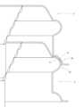
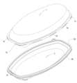
以下、本発明の好ましい実施の形態を添付した図面に従って説明する。図1は、本発明の一実施形態に係る包装用容器について、蓋体1と容器本体2を分離した状態を示した要部断面図である。これら蓋体1と容器本体2は、成形金型を用いた真空成形、圧空成形、真空圧空成形など、公知の樹脂シート成形法によって製造され、次のような構成を備える。 Preferred embodiments of the present invention will now be described with reference to the accompanying drawings. FIG. 1 is a cross-sectional view of the essential parts of a packaging container according to an embodiment of the present invention, showing a state in which a
蓋体1は、天板1aの周囲に傾斜壁1bを有し、該傾斜壁1bの周囲には水平なヘム部1cを介してスカート部1dを垂設している。スカート部1dは、ヘム部1cの下縁に連続してやや拡開気味に形成したフレア部1eと、該フレア部1eの下縁からさらに平面方向外向きに突出して形成した膨出部1fと、該膨出部1fの下縁に連続して形成した平面方向内向きに窪む嵌合用凹部1gとからなり、さらに嵌合用凹部1gには微小な水平フランジ1hを形成し、該水平フランジ1hの内側において下面1iは開口している。 The
容器本体2は、底2aとその周囲の立ち上がり壁2bとで上面開口の収容部2cを画定し、立ち上がり壁2bの周囲には、蓋体1のヘム部1c、フレア部1e、膨出部1fにそれぞれ対応するヘム部2d、フレア部2e、嵌合用凸部2fを形成している。また、この実施形態では、後述する容器本体2同士を積み重ねた際のスタック性を安定化させるために、嵌合用凸部2fの下側に垂壁部2gを介してスタック用裾部2hを形成している。さらに、このスタック用裾部2hには微小の水平フランジ2iを形成している。 The
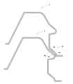
上記構成の包装用容器は、収容部2cに内容物を収容した容器本体2に蓋体1を被せ、この蓋体1のヘム部1cを下方に押し込む等することで、その内向きの嵌合用凹部1gの全体が容器本体2の嵌合用凸部2fの下方に外側から嵌り込んで、図2に示す外嵌合の状態で閉蓋をなすところ、本発明の特徴である、その外嵌合前に蓋体1を容器本体2に対して位置決めする構成について、さらに各部の詳細な形状等について説明する。 The packaging container configured as described above is made by putting the
上記構成の包装用容器は、その外嵌合前は、図3に示すように、蓋体1の嵌合用凹部1gの下部内面3が、容器本体2の嵌合用凸部2fの上部外面4に乗り、外嵌合時よりも蓋体1が容器本体2から浮いた半開きの状態をなすものであって、その際の位置決めについて、蓋体1側の乗る部分である上記下部内面3と、容器本体2側の乗られる部分である上記上部外面4はともに、外方に向かって下り、少なくとも一部において互いの形状が合致するアール値(半径)を有した断面弧状に形成している。 Before the outer fitting of the packaging container having the above structure, the lower
このように乗る側(嵌合用凹部1gの下部内面3)と乗られる側(嵌合用凸部2fの上部外面4)が、断面弧状として形状が合致することで、両者間に滑りが生じず、上述した半開きの状態で、蓋体1の容器本体2に対する平面方向の相対的な移動を規制することができる。よって、いったん位置決めを行えば、その状態を安定して維持し、その後、スムーズに嵌合(閉蓋)作業を実行することができる。 In this way, the riding side (lower
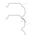
次に、蓋体1を容器本体2に位置決めするさらに、その前段階において、蓋体1同士、容器本体2同士を積み重ねたときのスタック安定性について説明すると、まず、蓋体1については、これを上下に積み重ねた際、図4に示すように、上位の蓋体1の嵌合用凹部1gの下部内面3が、下位の蓋体1の膨出部1fに乗る。そこで、本発明では、乗られる部分である膨出部1fの肩部5(請求の範囲における「スタック用肩部」)の外面部分5aと、ここに乗る嵌合用凹部1gの下部内面3とを、少なくとも一部において互いの形状が合致するアール値を有した断面弧状に形成している。 Next, the stacking stability when the
他方、容器本体2については、これを上下に積み重ねた際、図5に示すように、下位の容器本体2の嵌合用凸部2fの上部外面4に、上位の容器本体2のスタック用裾部2hの内面部分6が乗るため、これら部分4・6を、蓋体1の場合と同様に、少なくとも一部において互いの形状が合致するアール値を有した断面弧状に形成している。 On the other hand, when the
このような構成によって、蓋体1同士や容器本体2同士を積み重ねたときは、上述した蓋体1を容器本体2に位置決めしたときと同じ作用によって、蓋体1や容器本体2の平面方向の相対的な移動が規制され、安定したスタック性が得られる。 With such a configuration, when the
続いて、閉蓋後の包装用容器の作用効果について説明すると、本実施形態では、蓋体1の外嵌合後、図2に示したように、容器本体2の嵌合用凸部2fが蓋体1の膨出部1fの内側に完全に収容されるため、閉蓋状態を確実に安定して維持することができる。 Next, the function and effect of the packaging container after the lid is closed will be described. In this embodiment, after the
また、この実施形態では、蓋体1における嵌合用凹部1gの深さを大きくして、より強固な嵌合を実現している。具体的には、嵌合用凹部1gの最も内向きに突き出る先端7を、スタック用肩部5のフレア部1eとの接続部である基端部5bよりも内向きに突き出るように、嵌合用凹部1gの深さを設定している。これはすなわち、膨出部1fの内側の収容深さよりも嵌合用凹部1gの窪みが大きいことを意味し、容器本体2に対して嵌合用凹部1gがより深く嵌合することを意味する。よって、薄肉化の傾向が強い近年の包装用容器について、このように嵌合することで、より不用意な開蓋を防止することができる。Further, in this embodiment, the depth of the fitting
さらに、本実施形態では、蓋体1の水平フランジ1hを容器本体2の水平フランジ2iの上方に位置させており、容器本体2の水平フランジ2iによる下カバー作用によって、蓋体1の水平フランジ1hに下方からの力、即ち開蓋方向の力が直接作用することを防止し、もって、蓋体1の不用意な開蓋を確実に防止している。 Furthermore, in this embodiment, the
その一方で、意図する開蓋作業は確保されなければならない。そこで、この実施形態では、閉蓋時(外嵌合時)に、蓋体1の水平フランジ1hが容器本体2の水平フランジ2iよりも、僅かに外方に突出するように、両者フランジ1h・2iの突出長さを調整して形成している。よって、消費者が開蓋する際は、蓋体1の水平フランジ1hの先端に指をかけて、意図する開蓋を行うことができる。 On the other hand, the intended opening operation must be ensured. Therefore, in this embodiment, the
図6は、本発明の第二の実施形態に係る包装用容器を示すものであり、蓋体1の嵌合用凹部1gと容器本体2の嵌合用凸部2fに関して、下部内面3と上部外面4それぞれの形状を変更している。即ち、この第二実施形態では、嵌合用凹部1gの下部内面3と嵌合用凸部2fの上部内面4それぞれを、上述した断面弧状を有する先端部3a・4aと、その上側に連続する傾斜面3b・4bとで構成している。この他、上記実施形態と同一の構成は同一符号をもって説明する。 FIG. 6 shows a packaging container according to a second embodiment of the present invention. Each shape is changed. That is, in this second embodiment, the lower
上記先端部3a・4aが互いの形状が合致するアール値を有した断面弧状であることは上記実施形態と同じであり、この第二実施形態では、蓋側と本体側の双方に、同じか近似する角度を有する断面直線状の傾斜面3b・4bを構成一部に含んでいる。 It is the same as in the above-described embodiment that the
当該構成によれば、その外嵌合前は、図7に示すように、蓋体1の嵌合用凹部1gの下部内面3が、容器本体2の嵌合用凸部2fの上部外面4に乗り、外嵌合(閉蓋)時よりも蓋体1が容器本体2から浮いた半開きの状態をなすことは上記実施形態と同じであるが、その際の位置決めについては、蓋体1側の乗る部分である上記下部内面3と、容器本体2側の乗られる部分である上記上部外面4はともに、互いの傾斜面3b・4bが当接した状態となるため、当該下部内面3と上部外面4の全部を断面弧状とした場合よりも、これら部分の接触機会や面積が増し、より確実に位置決めができると共に、スタック性もより安定させることができる。 According to this configuration, before the external fitting, as shown in FIG. It is the same as the above-described embodiment that the
また、閉蓋操作では、蓋体1の傾斜面3bが容器本体2の傾斜面4bを滑るように移動するため、当該操作に必要な蓋体1の押圧力を小さくすることができ、蓋体1と容器本体2の双方への負担が小さくなるため、それぞれの樹脂シートの厚みを小さくしても、閉蓋操作時に嵌合用凹部1gや嵌合用凸部2fが潰れることを防止することができる。 In the lid closing operation, the
一方、図8・9に示すように、蓋体1同士や容器本体2同士を積み重ねた際も、蓋体1を半開きの状態で容器本体2に位置決めしたときと同じ作用によって、安定したスタック性が得られる。 On the other hand, as shown in FIGS. 8 and 9, even when the
特に、この実施形態では、容器本体2については、そのスタック用裾部2hの内面部分6は、先端部6aを嵌合用凸部2fの先端部4aと互いの形状が合致するアール値を有した断面弧状として、その上側に嵌合用凸部2fの上部外面4における傾斜面4bに対応した断面直線状の第二の傾斜面6bを連続して形成しているため、容器本体2同士を積み重ねた際は、図8に示したように、上位の第二傾斜面6bが下位の傾斜面4bに重畳して、より高いスタック性が得られる。 In particular, in this embodiment, regarding the
他方、図10に示す本発明の第三実施形態では、蓋体1は最初の実施形態と同一構成であるが、容器本体2については、その嵌合用凸部2fの上部外面4を、第二の実施形態と同一構成である傾斜面4bを含むものとしているため、蓋体1同士のスタック性(図12)は最初の実施形態と同じ作用効果が得られ、蓋体1の容器本体2に対する位置決めから嵌合までの容易性(図11)、及び容器本体2同士のスタック性(図13)については、第二実施形態に準ずる作用効果を期待することができる。 On the other hand, in the third embodiment of the present invention shown in FIG. 10, the
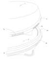
なお、本発明は上記実施形態に限定されないことはもちろんであって、ここまで言及していない容器の全体形状については、図14~図16に示すように、平面視円形、矩形等、何れであってもよい。また、特徴的構成においても、嵌合用凹部や嵌合用凸部は蓋体や容器本体の全周に設けてもよいし、一部に一つまたは二つ以上設けてもよい。この点、図14~図16に示したように、各種形状のいずれにおいても、容器本体2において嵌合用凸部2fは全周に設ける一方、蓋体1における嵌合用凹部1gは複数を間隔を空けて設けることが、位置決めのしやすさ、嵌合のしやすさ、意図した開蓋のしやすさなど、総合的にバランスが最も良いのであるが、逆に、嵌合用凹部1gを蓋体1の全周に設け、嵌合用凸部2fを間欠的に設けたものでも、同等の作用効果を期待することができる。 The present invention is, of course, not limited to the above embodiments, and the overall shape of the container not mentioned heretofore may be circular, rectangular, or the like in plan view, as shown in FIGS. 14 to 16. There may be. Also, in the characteristic structure, the fitting concave portion and the fitting convex portion may be provided on the entire circumference of the lid or the container body, or one or two or more may be provided on a part thereof. In this respect, as shown in FIGS. 14 to 16, in any of the various shapes, the
この他のパターンとして、嵌合用凹部1g・嵌合用凸部2fの双方ともを全周に設ける形態や、双方とも間欠的に設ける形態も本発明にて採用することが可能である。さらに、蓋体を容器本体に位置決めする構成は必須であるが、それ以外のスタック性、嵌合性、開蓋容易性に関する構成は副次的なものであって、適宜、省略することも可能である。As other patterns, the present invention can adopt a form in which both the fitting
さらにまた、寸法に関しては、一例として、次のように設定する。
0.7(0.9)≦r’/r≦3.0(2.5)
0.7(0.8)≦r’/r”≦2.0(1.5)
0.6(0.7)≦r’’’/r≦3.0(2.5)
ただし、rは容器本体2における嵌合用凸部2fの上部外面4のアール値、r’は蓋体1における嵌合用凹部1gの下部内面3のアール値、r”は蓋体1におけるスタック用肩部5の外面部分5aのアール値、r’’’は容器本体2におけるスタック用裾部2hの内面部分6のアール値であって、カッコ内の値は最適な比率である。Furthermore, as an example, the dimensions are set as follows.
0.7 (0.9) ≤ r'/r ≤ 3.0 (2.5)
0.7 (0.8) ≤ r'/r'' ≤ 2.0 (1.5)
0.6 (0.7) ≤ r''/r ≤ 3.0 (2.5)
However, r is the radius value of the upper
なお、上記のように各比率に上限値を設けたのは、この値を超えると、位置決め又はスタック時に乗る側が直線に近づき安定した位置決め又はスタック性が得られないからであり、また下限値については、乗る側の曲率が乗られる側よりも大きくなり、相対移動を規制することが困難となるからである。 The reason why the upper limit is set for each ratio as described above is that if this value is exceeded, the riding side approaches a straight line during positioning or stacking, making it impossible to obtain stable positioning or stacking. This is because the curvature of the riding side is larger than that of the riding side, making it difficult to restrict relative movement.
1 蓋体
1a 天板
1b 傾斜壁
1c ヘム部
1d スカート部
1e フレア部
1f 膨出部
1g 嵌合用凹部
1h 水平フランジ
1i 下面
2 容器本体
2a 底
2b 立ち上がり壁
2c 収容部
2d ヘム部
2e フレア部
2f 嵌合用凸部
2g 垂壁部
2h スタック用裾部
2i 水平フランジ
3 嵌合用凹部の下部内面
3a 断面弧状の先端部
3b 断面直線状の傾斜面
4 嵌合用凸部の上部外面
4a 断面弧状の先端部
4b 断面直線状の傾斜面
5 スタック用肩部
5a スタック用肩部の外面部分
6 スタック用裾部の内面部分
6a 断面弧状の先端部
6b 断面直線状の傾斜面
7 嵌合用凹部の最先端1
Claims (9)
Translated fromJapanese前記容器本体は、底と、前記底の周囲の立ち上がり壁と、前記底と前記立ち上がり壁とで画定される上面開口の収容部と、前記立ち上がり壁の周囲には水平なヘム部と、前記ヘム部に連続して外方へ拡開形成したフレア部とを有し、
前記容器本体側において前記フレア部の下端から平面方向外向きに突出する嵌合用凸部と、前記蓋体側において平面方向内向きに窪む嵌合用凹部とを備え、
外嵌合時は、前記嵌合用凹部の全体が外側から前記嵌合用凸部の下方に嵌り込んで閉蓋状態をなす一方、
外嵌合前は、前記嵌合用凹部の下部内面が前記嵌合用凸部の上部外面に乗って、前記フレア部の下縁よりも外方に前記嵌合用凹部の最先端が位置し、前記外嵌合時よりも前記蓋体が前記容器本体から浮いた半開きの状態をなす包装用容器であって、
前記嵌合用凹部の前記下部内面、及び前記嵌合用凸部の前記上部外面はともに、外方に向かって下り、少なくとも一部において互いの形状が合致するアール値を有した断面弧状に形成され、前記半開きの状態で、前記蓋体の前記容器本体に対する平面方向の相対的な移動を規制し、
前記容器本体は、前記嵌合用凸部の下側に、当該容器本体同士を積み重ねるスタック用裾部を有し、該スタック用裾部は、下位の容器本体の前記嵌合用凸部の上部外面に乗る内面部分が、前記嵌合用凸部の上部外面と少なくとも一部において互いの形状が合致するアール値を有した断面弧状であることを特徴とする包装用容器。As a fitting structure for externally fitting the lid to the container body,
The container body includes a bottom, a raised wall around the bottom, a housing portion with an upper opening defined by the bottom and the raised wall, a horizontal hem portion around the raised wall, and the hem. and a flared portion continuously expanding outward from the portion,
a fitting protrusion protruding outward in the planar direction from the lower end of the flared portion on the container body side, and a fitting recess recessed inward in the planar direction on the lid body side,
At the time of external fitting, the entire fitting concave portion is fitted from the outside to below the fitting convex portion to form a closed lid state,
Before the outer fitting, the lower inner surface of the fitting recess rides on the upper outer surface of the fitting protrusion, and the tip of the fitting recess is located outside the lower edge of the flared portion. A packaging container in a half-open state in which the lid body is lifted from the container body more than when it is fitted,
The lower inner surface of the fitting concave portion and the upper outer surface of the fitting convex portion both descend outward and are formed in an arcuate cross-section having a radius value that at least partially matches each other, In the half-open state, restricting relative movement of the lid in a planar direction with respect to the container body;
The container body has a stacking hem for stacking the container bodies on the lower side of the fitting projection, and the stacking hem is attached to the upper outer surface of the fitting projection of the lower container body. A packaging container, wherein an inner surface portion on which the packaging container rides has an arcuate cross-section having a radius value that matches the shape of the upper outer surface of the fitting projection at least partially.
Applications Claiming Priority (2)
| Application Number | Priority Date | Filing Date | Title |
|---|---|---|---|
| JP2017157573 | 2017-08-17 | ||
| JP2017157573 | 2017-08-17 |
Publications (2)
| Publication Number | Publication Date |
|---|---|
| JP2019034791A JP2019034791A (en) | 2019-03-07 |
| JP7272616B2true JP7272616B2 (en) | 2023-05-12 |
Family
ID=65636607
Family Applications (1)
| Application Number | Title | Priority Date | Filing Date |
|---|---|---|---|
| JP2018149145AActiveJP7272616B2 (en) | 2017-08-17 | 2018-08-08 | packaging container |
Country Status (1)
| Country | Link |
|---|---|
| JP (1) | JP7272616B2 (en) |
Families Citing this family (5)
| Publication number | Priority date | Publication date | Assignee | Title |
|---|---|---|---|---|
| JP7213772B2 (en)* | 2019-07-23 | 2023-01-27 | リスパック株式会社 | container |
| JP7496589B2 (en)* | 2019-12-11 | 2024-06-07 | シーピー化成株式会社 | Packaging containers |
| CN117383059A (en)* | 2023-11-10 | 2024-01-12 | 新天力科技股份有限公司 | Structure of plastic uptake packing container |
| WO2024088447A2 (en)* | 2024-02-05 | 2024-05-02 | 佛山市美万邦科技有限公司 | Paper pulp molded cup lid |
| JP2025127717A (en)* | 2024-02-21 | 2025-09-02 | 株式会社エフピコ | packaging containers |
Citations (4)
| Publication number | Priority date | Publication date | Assignee | Title |
|---|---|---|---|---|
| JP2005263284A (en) | 2004-03-19 | 2005-09-29 | Fp Corp | Packaging container |
| US20060186014A1 (en) | 2005-02-23 | 2006-08-24 | Anand Ramanujam | Container |
| US20080217346A1 (en) | 2007-03-06 | 2008-09-11 | Dixie Consumer Products Llc | Filled polystyrene tear back container lids |
| JP2019189289A (en) | 2018-04-25 | 2019-10-31 | シーピー化成株式会社 | Packaging container |
Family Cites Families (5)
| Publication number | Priority date | Publication date | Assignee | Title |
|---|---|---|---|---|
| JPH0287777U (en)* | 1988-12-27 | 1990-07-11 | ||
| JPH09226769A (en)* | 1996-02-23 | 1997-09-02 | Sumi Kk | Externally fitting-sealing type packaging container |
| JPH10230954A (en)* | 1997-02-14 | 1998-09-02 | Sumi Kk | Packaging container of outside fitting and hermetically sealing and easily closable cover type |
| JP3288604B2 (en)* | 1997-04-02 | 2002-06-04 | 旭化成パックス株式会社 | Packaging containers |
| JP5610951B2 (en)* | 2010-09-22 | 2014-10-22 | 株式会社エフピコ | Molded lid |
- 2018
- 2018-08-08JPJP2018149145Apatent/JP7272616B2/enactiveActive
Patent Citations (4)
| Publication number | Priority date | Publication date | Assignee | Title |
|---|---|---|---|---|
| JP2005263284A (en) | 2004-03-19 | 2005-09-29 | Fp Corp | Packaging container |
| US20060186014A1 (en) | 2005-02-23 | 2006-08-24 | Anand Ramanujam | Container |
| US20080217346A1 (en) | 2007-03-06 | 2008-09-11 | Dixie Consumer Products Llc | Filled polystyrene tear back container lids |
| JP2019189289A (en) | 2018-04-25 | 2019-10-31 | シーピー化成株式会社 | Packaging container |
Also Published As
| Publication number | Publication date |
|---|---|
| JP2019034791A (en) | 2019-03-07 |
Similar Documents
| Publication | Publication Date | Title |
|---|---|---|
| JP7272616B2 (en) | packaging container | |
| RU2443611C2 (en) | Container set with piling appliance | |
| US5676272A (en) | Metal container having resilient interface ring | |
| US20180273254A1 (en) | Tamper-evident thermoformed packaging | |
| US10940980B1 (en) | Disposable cup lid | |
| US20130341342A1 (en) | Plastic container and lid | |
| JPS60502097A (en) | Container and method of manufacturing this container | |
| JP2001122305A (en) | Fitting container | |
| JP2014091540A (en) | Packaging container | |
| US20170267419A1 (en) | Cover for a container | |
| JP4364561B2 (en) | Container stacking structure | |
| JP2020093845A (en) | Packaging container | |
| US11472614B2 (en) | Disposable cup lid | |
| US5261537A (en) | Container | |
| JP2023180694A (en) | garbage container | |
| JP2019127301A (en) | Inner fitting container for packaging | |
| JP7266291B2 (en) | packaging container | |
| JP2020093843A (en) | Packaging container | |
| JP2020093834A (en) | Packaging container | |
| CN215099307U (en) | Flip formula stereoplasm packing carton | |
| CN215246803U (en) | Fruit packing box with fastener | |
| JP3180260U (en) | Packaging container | |
| US12208947B2 (en) | Two-piece child resistant container lid with push-release latch arrangement | |
| JP4646555B2 (en) | Packaging container lid | |
| JP7374452B2 (en) | Lid body |
Legal Events
| Date | Code | Title | Description |
|---|---|---|---|
| A621 | Written request for application examination | Free format text:JAPANESE INTERMEDIATE CODE: A621 Effective date:20210721 | |
| A977 | Report on retrieval | Free format text:JAPANESE INTERMEDIATE CODE: A971007 Effective date:20220616 | |
| A131 | Notification of reasons for refusal | Free format text:JAPANESE INTERMEDIATE CODE: A131 Effective date:20220628 | |
| A521 | Request for written amendment filed | Free format text:JAPANESE INTERMEDIATE CODE: A523 Effective date:20220809 | |
| A131 | Notification of reasons for refusal | Free format text:JAPANESE INTERMEDIATE CODE: A131 Effective date:20221129 | |
| A521 | Request for written amendment filed | Free format text:JAPANESE INTERMEDIATE CODE: A523 Effective date:20221215 | |
| TRDD | Decision of grant or rejection written | ||
| A01 | Written decision to grant a patent or to grant a registration (utility model) | Free format text:JAPANESE INTERMEDIATE CODE: A01 Effective date:20230328 | |
| A61 | First payment of annual fees (during grant procedure) | Free format text:JAPANESE INTERMEDIATE CODE: A61 Effective date:20230420 | |
| R150 | Certificate of patent or registration of utility model | Ref document number:7272616 Country of ref document:JP Free format text:JAPANESE INTERMEDIATE CODE: R150 |