JP7272032B2 - connector - Google Patents
connectorDownload PDFInfo
- Publication number
- JP7272032B2 JP7272032B2JP2019052639AJP2019052639AJP7272032B2JP 7272032 B2JP7272032 B2JP 7272032B2JP 2019052639 AJP2019052639 AJP 2019052639AJP 2019052639 AJP2019052639 AJP 2019052639AJP 7272032 B2JP7272032 B2JP 7272032B2
- Authority
- JP
- Japan
- Prior art keywords
- connector
- cover
- housing
- accommodating portion
- fitting
- Prior art date
- Legal status (The legal status is an assumption and is not a legal conclusion. Google has not performed a legal analysis and makes no representation as to the accuracy of the status listed.)
- Active
Links
Images


Classifications
- H—ELECTRICITY
- H01—ELECTRIC ELEMENTS
- H01R—ELECTRICALLY-CONDUCTIVE CONNECTIONS; STRUCTURAL ASSOCIATIONS OF A PLURALITY OF MUTUALLY-INSULATED ELECTRICAL CONNECTING ELEMENTS; COUPLING DEVICES; CURRENT COLLECTORS
- H01R13/00—Details of coupling devices of the kinds covered by groups H01R12/70 or H01R24/00 - H01R33/00
- H01R13/46—Bases; Cases
- H01R13/516—Means for holding or embracing insulating body, e.g. casing, hoods
- H—ELECTRICITY
- H01—ELECTRIC ELEMENTS
- H01R—ELECTRICALLY-CONDUCTIVE CONNECTIONS; STRUCTURAL ASSOCIATIONS OF A PLURALITY OF MUTUALLY-INSULATED ELECTRICAL CONNECTING ELEMENTS; COUPLING DEVICES; CURRENT COLLECTORS
- H01R13/00—Details of coupling devices of the kinds covered by groups H01R12/70 or H01R24/00 - H01R33/00
- H01R13/46—Bases; Cases
- H01R13/502—Bases; Cases composed of different pieces
- H—ELECTRICITY
- H01—ELECTRIC ELEMENTS
- H01R—ELECTRICALLY-CONDUCTIVE CONNECTIONS; STRUCTURAL ASSOCIATIONS OF A PLURALITY OF MUTUALLY-INSULATED ELECTRICAL CONNECTING ELEMENTS; COUPLING DEVICES; CURRENT COLLECTORS
- H01R13/00—Details of coupling devices of the kinds covered by groups H01R12/70 or H01R24/00 - H01R33/00
- H01R13/46—Bases; Cases
- H01R13/50—Bases; Cases formed as an integral body
- H01R13/501—Bases; Cases formed as an integral body comprising an integral hinge or a frangible part
- H—ELECTRICITY
- H01—ELECTRIC ELEMENTS
- H01R—ELECTRICALLY-CONDUCTIVE CONNECTIONS; STRUCTURAL ASSOCIATIONS OF A PLURALITY OF MUTUALLY-INSULATED ELECTRICAL CONNECTING ELEMENTS; COUPLING DEVICES; CURRENT COLLECTORS
- H01R13/00—Details of coupling devices of the kinds covered by groups H01R12/70 or H01R24/00 - H01R33/00
- H01R13/62—Means for facilitating engagement or disengagement of coupling parts or for holding them in engagement
- H01R13/627—Snap or like fastening
- H01R13/6271—Latching means integral with the housing
- H01R13/6272—Latching means integral with the housing comprising a single latching arm
- H—ELECTRICITY
- H01—ELECTRIC ELEMENTS
- H01R—ELECTRICALLY-CONDUCTIVE CONNECTIONS; STRUCTURAL ASSOCIATIONS OF A PLURALITY OF MUTUALLY-INSULATED ELECTRICAL CONNECTING ELEMENTS; COUPLING DEVICES; CURRENT COLLECTORS
- H01R13/00—Details of coupling devices of the kinds covered by groups H01R12/70 or H01R24/00 - H01R33/00
- H01R13/62—Means for facilitating engagement or disengagement of coupling parts or for holding them in engagement
- H01R13/629—Additional means for facilitating engagement or disengagement of coupling parts, e.g. aligning or guiding means, levers, gas pressure electrical locking indicators, manufacturing tolerances
- H01R13/631—Additional means for facilitating engagement or disengagement of coupling parts, e.g. aligning or guiding means, levers, gas pressure electrical locking indicators, manufacturing tolerances for engagement only
- H—ELECTRICITY
- H01—ELECTRIC ELEMENTS
- H01R—ELECTRICALLY-CONDUCTIVE CONNECTIONS; STRUCTURAL ASSOCIATIONS OF A PLURALITY OF MUTUALLY-INSULATED ELECTRICAL CONNECTING ELEMENTS; COUPLING DEVICES; CURRENT COLLECTORS
- H01R13/00—Details of coupling devices of the kinds covered by groups H01R12/70 or H01R24/00 - H01R33/00
- H01R13/62—Means for facilitating engagement or disengagement of coupling parts or for holding them in engagement
- H01R13/639—Additional means for holding or locking coupling parts together, after engagement, e.g. separate keylock, retainer strap
- H—ELECTRICITY
- H01—ELECTRIC ELEMENTS
- H01R—ELECTRICALLY-CONDUCTIVE CONNECTIONS; STRUCTURAL ASSOCIATIONS OF A PLURALITY OF MUTUALLY-INSULATED ELECTRICAL CONNECTING ELEMENTS; COUPLING DEVICES; CURRENT COLLECTORS
- H01R13/00—Details of coupling devices of the kinds covered by groups H01R12/70 or H01R24/00 - H01R33/00
- H01R13/64—Means for preventing incorrect coupling
Landscapes
- Connector Housings Or Holding Contact Members (AREA)
- Details Of Connecting Devices For Male And Female Coupling (AREA)
Description
Translated fromJapanese本開示は、コネクタに関する。 The present disclosure relates to connectors.
従来より、カバーの開閉動作でコネクタの半嵌合を検知できるコネクタ嵌合検知構造として、特開平10-223313号公報(下記特許文献1)に記載のコネクタ嵌合検知構造が知られている。コネクタ嵌合検知構造は、雌コネクタと、一対のカバーと、を備える。カバーは押圧用傾斜壁を備え、半嵌合状態の場合には押圧用傾斜壁が雄コネクタの後段部を押圧することで雄コネクタが雌コネクタに押し込まれるようになっており、この押し込みの様子を外部から視認しながら一対のカバーを閉じることができる。 Conventionally, a connector fitting detection structure described in Japanese Patent Application Laid-Open No. 10-223313 (Patent Document 1 below) is known as a connector fitting detection structure capable of detecting incomplete fitting of a connector by opening and closing a cover. The connector fitting detection structure includes a female connector and a pair of covers. The cover has a pressing inclined wall, and in the half-fitted state, the pressing inclined wall presses the rear part of the male connector, thereby pushing the male connector into the female connector. The pair of covers can be closed while viewing from the outside.
しかしながら、雌雄のコネクタが一対のカバーによって完全に覆われる構成では、嵌合状態を外部から視認できないため、カバーの組み付け後に半嵌合状態に気付いた際にはカバーを外して半嵌合状態から完全嵌合状態に移行させ、カバーを再び組み付ける必要がある。 However, in a configuration in which the male and female connectors are completely covered by a pair of covers, the mated state cannot be visually recognized from the outside. It is necessary to move to full mating condition and reassemble the cover.
本開示のコネクタは、第1コネクタと、第2コネクタと、カバーと、を備えたコネクタであって、前記第1コネクタと前記第2コネクタは互いに嵌合可能とされ、完全嵌合状態で前記カバーによって完全に覆われており、前記カバーは、前記第1コネクタを内部に収容する第1カバーと、前記第2コネクタを内部に収容する第2カバーと、を備え、前記第2カバーは、開閉可能な一対の半割カバーを備えて構成され、前記半割カバーは、完全嵌合状態にある前記第2コネクタに後方から当接する嵌合保証部を備える、コネクタである。 A connector of the present disclosure includes a first connector, a second connector, and a cover, wherein the first connector and the second connector are matable with each other, and in a completely mated state, the completely covered by a cover, the cover comprising: a first cover containing the first connector therein; and a second cover containing the second connector therein, the second cover comprising: The connector comprises a pair of openable and closable half-covers, the half-covers having a fitting assurance portion that abuts from the rear on the second connector in a completely fitted state.
本開示によれば、カバーの組み付け完了をもってコネクタの嵌合保証が可能である。 According to the present disclosure, it is possible to guarantee the mating of the connector upon completion of assembly of the cover.
[本開示の実施形態の説明]
最初に本開示の実施形態を列記して説明する。[Description of Embodiments of the Present Disclosure]
First, the embodiments of the present disclosure will be listed and described.
本開示のコネクタは、
(1)第1コネクタと、第2コネクタと、カバーと、を備えたコネクタであって、前記第1コネクタと前記第2コネクタは互いに嵌合可能とされ、完全嵌合状態で前記カバーによって完全に覆われており、前記カバーは、前記第1コネクタを内部に収容する第1カバーと、前記第2コネクタを内部に収容する第2カバーと、を備え、前記第2カバーは、開閉可能な一対の半割カバーを備えて構成され、前記半割カバーは、完全嵌合状態にある前記第2コネクタに後方から当接する嵌合保証部を備える、コネクタである。The connector of the present disclosure is
(1) A connector comprising a first connector, a second connector, and a cover, wherein the first connector and the second connector can be mated with each other, and in a completely mated state, the cover completely seals the connector. The cover includes a first cover that accommodates the first connector inside, and a second cover that accommodates the second connector inside, the second cover being openable and closable. The connector comprises a pair of half-split covers, wherein the half-split covers are provided with a mating assurance portion that abuts from the rear on the second connector in a completely mated state.
第1コネクタと第2コネクタがカバーによって完全に覆われて外部から視認できない場合でも、一対の半割カバーが閉じられて嵌合保証部が第2コネクタに後方から当接することで完全嵌合状態であることを検知できる。すなわち、カバーの組み付け完了をもってコネクタの嵌合保証が可能である。 Even when the first connector and the second connector are completely covered by the cover and cannot be visually recognized from the outside, the pair of half-split covers are closed and the mating assurance part abuts the second connector from the rear to bring about a completely mated state. can be detected. That is, it is possible to guarantee the mating of the connector when the cover is completely assembled.
(2)前記第2カバーは、前記第2コネクタの外面に沿って嵌合方向に延びる形態をなし、前記嵌合保証部は、前記半割カバーの内面から嵌合方向と直交する方向に突出した突部を有することが好ましい。第2カバーの外形を嵌合方向と直交する方向に大きくしなくてもよく、コネクタを小型化できる。(2) The second cover extends in the fitting direction along the outer surface of the second connector, and the fitting assurance portion protrudes from the inner surface of the half cover in a direction orthogonal to the fitting direction. It is preferable to have a raised protrusion. The outer shape of the second cover does not have to be enlarged in the direction orthogonal to the fitting direction, and the connector can be made smaller.
(3)前記突部は、半嵌合状態にある前記第2コネクタを前記第1コネクタに向けて押し込む傾斜面を有することが好ましい。第2コネクタが半嵌合状態にある場合でも、傾斜面によって第2コネクタを第1コネクタに向けて押し込んで完全嵌合状態に移行できる。(3) It is preferable that the protrusion has an inclined surface for pushing the second connector in the half-fitted state toward the first connector. Even when the second connector is in the half-fitted state, the inclined surface allows the second connector to be pushed toward the first connector to transition to the fully-fitted state.
[本開示の実施形態の詳細]
本開示のコネクタ10の具体例を、以下に図面を参照しつつ説明する。なお、本開示はこれらの例示に限定されるものではなく、特許請求の範囲によって示され、特許請求の範囲と均等の意味および範囲内でのすべての変更が含まれることが意図される。[Details of the embodiment of the present disclosure]
A specific example of the
<実施形態>
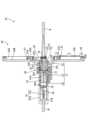
実施形態を図1から図6の図面を参照しながら説明する。本実施形態のコネクタ10は、図3に示すように、第1コネクタ20と、第2コネクタ30と、カバー40と、を備えて構成されている。コネクタ10は、車両のサスペンションに用いられる。<Embodiment>
Embodiments will be described with reference to the drawings of FIGS. 1 to 6. FIG. The
第1コネクタ20は合成樹脂製の第1ハウジング21を有している。第1ハウジング21は、前から順に、円筒状のフード部22と、図示しない端子が保持された円柱状の端子保持部23と、円筒状のゴム栓収容部24と、を備えている。電線Wの端末は図示しない端子に接続されている。ゴム栓収容部24の内部にはゴム栓25が収容されている。 The
第2コネクタ30は合成樹脂製の第2ハウジング31を有している。第2ハウジング31は、前から順に、図示しない端子が保持された円柱状の端子保持部32と、円筒状のゴム栓収容部33と、を備えている。電線Wの端末は図示しない端子に接続されている。ゴム栓収容部33の内部にはゴム栓34が収容されている。 The
第1ハウジング21のフード部22は、大径部22Aと、小径部22Bと、を備えて構成されている。大径部22Aは小径部22Bと同軸をなすように配されている。大径部22Aは小径部22Bよりも径が大きい。大径部22Aの内部は小径部22Bの内部と連通している。 The
小径部22Bの上部には、第1平面部22Cが設けられている。一方、第2ハウジング31の端子保持部32の上部には、第2平面部32Aが設けられている。第1ハウジング21と第2ハウジング31を組み付ける際には、第1平面部22Cと第2平面部32Aが面接触するように回転方向の位置決めが行われる。第1ハウジング21と第2ハウジング31が組み付けられた状態では第1平面部22Cと第2平面部32Aが互いに干渉することで第1ハウジング21と第2ハウジング31の回転方向の移動が規制される。 A
第1ハウジング21の第1平面部22Cにはロック部26が設けられている。ロック部26は上下方向に変位可能である。一方、第2ハウジング31の第2平面部32Aには被ロック部35が設けられている。第2ハウジング31の端子保持部32が第1ハウジング21のフード部22の内部に嵌合する途中では、ロック部26が被ロック部35に乗り上げへ上方に変位する。端子保持部32がフード部22の内部に嵌合すると、ロック部26が被ロック部35を乗り越えて下方に変位し、ロック部26と被ロック部35が係止する。これにより両ハウジング21、31が嵌合状態に保持される。 A
フード部22の大径部22Aの内部にはシールリング27が装着されている。第2ハウジング31の端子保持部32が第1ハウジング21のフード部22の内部に嵌合すると、シールリング27が端子保持部32の外周面と大径部22Aの内周面との間に挟持される。これにより、両ハウジング21、31の嵌合部からフード部22の内部に水が浸入することが規制される。 A
第1ハウジング21のゴム栓25によって端子保持部23の内部に水が浸入することが規制される。また、第2ハウジング31のゴム栓34によって端子保持部32の内部に水が浸入することが規制される。このようにして第1コネクタ20と第2コネクタ30の内部に水が浸入することが規制される。 The rubber plug 25 of the
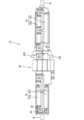
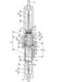
カバー40は合成樹脂製であって、図1、図2に示すように、第1カバー41と、第2カバー42と、を備えて構成されている。第1カバー41は第1コネクタ20を覆っており、第2カバー42は第2コネクタ30を覆っている。コネクタ10はカバー40によって完全に覆われており、外部から視認できないようになっている。 The
第1カバー41は上下一対の第1半割カバー41U、41Lを組み合わせたものであり、第2カバー42は上下一対の第2半割カバー42U、42Lを組み合わせたものである。上側の第1半割カバー41Uと上側の第2半割カバー42Uとは上側ヒンジ43Uによって連結され、開閉可能とされている。下側の第1半割カバー41Lと下側の第2半割カバー42Lとは下側ヒンジ43Lによって連結され、開閉可能とされている。したがって、第1カバー41が閉じられた状態における上下一対の第2半割カバー42U、42Lは開閉可能である。 The
下側の第1半割カバー41Lと下側の第2半割カバー42Lの側面には複数のカバーロック片44が設けられている。一方、上側の第1半割カバー41Uと上側の第2半割カバー42Uの側面には複数のロック受け部45が設けられている。図4に示すように、第1カバー41における各カバーロック片44が各ロック受け部45に係止されることで上側の第1半割カバー41Uと下側の第1半割カバー41Lとが一体に固定される。続けて、第2カバー42における各カバーロック片44が各ロック受け部45に係止されることで上側の第2半割カバー42Uと下側の第2半割カバー42Lとが一体に固定される。 A plurality of
図3に示すように、第1カバー41は、第1コネクタ20の外面に沿って嵌合方向に延びる形態をなしている。このため、第1カバー41の外形を嵌合方向と直交する方向に大きくしなくてもよく、コネクタ10を小型化できる。第1カバー41は、第1ハウジング21を内部に収容する第1ハウジング収容部41Hと、第1ハウジング収容部41Hの後方に引き出された電線Wを内部に収容する第1電線収容部41Wと、を有する。第1ハウジング収容部41Hは第1電線収容部41Wと前後方向の長さが同じか、これよりやや短めとされている。このため、電線Wが曲げられてもゴム栓25が変形しにくくなっている。 As shown in FIG. 3, the
第1ハウジング収容部41Hと第1電線収容部41Wの間には、上下一対の第1突部46が設けられている。第1突部46は、第1ハウジング21の外周面に沿って周方向に延びる形態とされている。第1ハウジング21は、第1ハウジング収容部41Hの前端部と第1突部46との間に適合して収容されている。ここで、適合とは、第1ハウジング21の外面と第1ハウジング収容部41Hの内面との間に全く隙間がない場合と、わずかな隙間がある場合との双方を含むことを意味する。したがって、第1ハウジング21が第1ハウジング収容部41Hの内部に収容されてカバーロック片44とロック受け部45が互いに係止したことにより、第1ハウジング21が第1ハウジング収容部41Hに対して正規の位置に収容されたことになる。 A pair of upper and lower
第1突部46は前方に向かうほど径方向外側に向かうテーパー状の第1傾斜面46Aを有する。第1ハウジング21が正規の位置に対してわずかに後方にずれている場合に第1カバー41が閉じられると、第1ハウジング21の後端が第1傾斜面46Aに当接することで第1ハウジング21が前方に押し込まれて正規の位置に移動し、第1カバー41が閉じられる。 The
第2カバー42は、第2コネクタ30の外面に沿って嵌合方向に延びる形態をなしている。このため、第2カバー42を嵌合方向と直交する方向に大きくしなくてもよく、コネクタ10を小型化できる。第2カバー42は、第2ハウジング31を内部に収容する第2ハウジング収容部42Hと、第2ハウジング収容部42Hの後方に引き出された電線Wを内部に収容する第2電線収容部42Wと、を有する。第2ハウジング収容部42Hは第2電線収容部42Wよりも前後方向の長さが短めとされている。また、第2電線収容部42Wは第1電線収容部41Wの2倍程度の長さで形成されている。このため、電線Wが曲げられてもゴム栓34が変形することはなく、防水性能に影響を及ぼすことはない。
The
図5に示すように、本実施形態では第1コネクタ20が第1カバー41によって覆われた状態とした後に、第2コネクタ30が第2カバー42によって覆われることで、コネクタ10全体がカバー40によって完全に覆われることになる。第2カバー42が開いた状態では、第2コネクタ30の大部分が第1カバー41によって覆われているため、第1コネクタ20と第2コネクタ30の嵌合状態を視認できないようになっている。したがって、第1コネクタ20と第2コネクタ30が半嵌合状態であることに気付かないまま第2カバー42が閉められる動作が開始されることが起こり得る。 As shown in FIG. 5, in this embodiment, after the
そこで、本実施形態では完全嵌合状態にある第2コネクタ30に後方から当接する上下一対の第2突部(嵌合保証部)47が設けられている。完全嵌合状態とは、第1コネクタ20と第2コネクタ30が正規に嵌合してロック部26と被ロック部35が互いに係止した状態のことを意味する。 Therefore, in the present embodiment, a pair of upper and lower second protrusions (fitting assurance portions) 47 are provided to abut on the
上下一対の第2突部47は、第2ハウジング収容部42Hと第2電線収容部42Wの間に設けられている。第2突部47は、第2ハウジング31の外周面に沿って周方向に延びる形態とされている。第2ハウジング31は、第2ハウジング収容部42Hの前端部と第2突部47との間に適合して収容されている。ここで、適合とは、第2ハウジング31の外面と第2ハウジング収容部42Hの内面との間に全く隙間がない場合と、わずかな隙間がある場合との双方を含むことを意味する。したがって、第2ハウジング31が第2ハウジング収容部42Hの内部に収容されてカバーロック片44とロック受け部45が互いに係止したことにより、第2ハウジング31が第2ハウジング収容部42Hに対して正規の位置に収容されたことになる。これと同時に、第1コネクタ20と第2コネクタ30が完全嵌合状態にあることが保証される。すなわち、第2カバー42の組み付け完了をもってコネクタ10の嵌合保証が可能である。 A pair of upper and lower
図6に示すように、第2突部47は前方に向かうほど径方向外側に向かうテーパー状の第2傾斜面47Aを有する。第2ハウジング31が正規の位置に対してわずかに後方にずれている場合に第2カバー42が閉じられると、第2ハウジング31の後端が第2傾斜面47Aに当接することで第2ハウジング31が前方に押し込まれて正規の位置に移動し、第2カバー42が閉じられる。これにより、第2コネクタ30を第1コネクタ20に向けて押し込んで半嵌合状態から完全嵌合状態に移行できるようになっている。 As shown in FIG. 6, the second projecting
<他の実施形態>
(1)上記実施形態では第2ハウジング31の後端に第2突部47が当接しているものの、第2ハウジング31の外周面に突起を設け、この突起に第2突部が後方から当接するようにしてもよい。<Other embodiments>
(1) Although the
(2)上記実施形態では第2突部47が第2傾斜面47Aを有する構成としているものの、第2突部の先端が球形状のものとしてもよい。 (2) In the above embodiment, the
(3)第2突部は、第2ハウジング31の後端に対して弾性的に接触するようにしてもよい。 (3) The second protrusion may elastically contact the rear end of the
10…コネクタ
20…第1コネクタ
21…第1ハウジング
22…フード部
22A…大径部
22B…小径部
22C…第1平面部
23…端子保持部
24…ゴム栓収容部
25…ゴム栓
26…ロック部
27…シールリング
30…第2コネクタ
31…第2ハウジング
32…端子保持部
32A…第2平面部
33…ゴム栓収容部
34…ゴム栓
35…被ロック部
40…カバー
41…第1カバー
41U、41L…第1半割カバー
41H…第1ハウジング収容部
41W…第1電線収容部
42…第2カバー
42U、42L…第2半割カバー
42H…第2ハウジング収容部
42W…第2電線収容部
43U…上側ヒンジ
43L…下側ヒンジ
44…カバーロック片
45…ロック受け部
46…第1突部
46A…第1傾斜面
47…第2突部(嵌合保証部)
47A…第2傾斜面
W…電線
47A... Second inclined plane W... Electric wire
Claims (3)
Translated fromJapanese前記第1コネクタと前記第2コネクタは互いに嵌合可能とされ、完全嵌合状態で前記カバーによって完全に覆われており、
前記カバーは、前記第1コネクタを内部に収容する第1カバーと、前記第2コネクタを内部に収容する第2カバーと、を備え、
前記第2カバーは、開閉可能な一対の半割カバーを備えて構成され、
前記半割カバーは、完全嵌合状態にある前記第2ハウジングに後方から当接する嵌合保証部を備え、
前記一対の半割カバーが組み合わされた状態の前記第2カバーは、前記第2ハウジングを内部に収容する第2ハウジング収容部と、前記第2ハウジング収容部の後端から後方に引き出された電線を内部に収容する第2電線収容部と、を有し、
前記嵌合保証部は、前記第2ハウジング収容部と前記第2電線収容部の間に設けられており、
前記第2ハウジングは、前記第2ハウジング収容部の前端部と前記嵌合保証部との間に適合して収容されており、
前記第2電線収容部は前記第2ハウジング収容部よりも前後方向に長く形成されている、コネクタ。A connector comprising a first connector, a second connector having a second housing, and a cover,
The first connector and the second connector are matable with each other, and are completely covered by the cover in a fully mated state,
The cover includes a first cover that accommodates the first connector inside, and a second cover that accommodates the second connector inside,
The second cover is configured with a pair of half covers that can be opened and closed,
the half-split cover has a fit assurance portion that abuts from the rear on the second housing that is in the completely fitted state;
The second cover in a state in which the pair of half-split covers are assembled includes a second housing accommodating portion that accommodates the second housing therein, and electric wires drawn out rearwardfrom the rear end of the second housing accommodating portion. and a second wire housing portion for housing the
The fitting assurance portion is provided between the second housing accommodating portion and the second wire accommodating portion,
The second housingis accommodated by fitting between a front end portion of the second housing accommodating portion and the fitting assurance portion,
The connector, wherein the second wire accommodating portion is longer in the front-rear direction than the second housing accommodating portion .
Priority Applications (3)
| Application Number | Priority Date | Filing Date | Title |
|---|---|---|---|
| JP2019052639AJP7272032B2 (en) | 2019-03-20 | 2019-03-20 | connector |
| CN202010134896.8ACN111725651B (en) | 2019-03-20 | 2020-03-02 | Connector with a locking member |
| US16/821,956US11139613B2 (en) | 2019-03-20 | 2020-03-17 | Connector assembly with automatic connection completion detection structure |
Applications Claiming Priority (1)
| Application Number | Priority Date | Filing Date | Title |
|---|---|---|---|
| JP2019052639AJP7272032B2 (en) | 2019-03-20 | 2019-03-20 | connector |
Publications (2)
| Publication Number | Publication Date |
|---|---|
| JP2020155310A JP2020155310A (en) | 2020-09-24 |
| JP7272032B2true JP7272032B2 (en) | 2023-05-12 |
Family
ID=72515280
Family Applications (1)
| Application Number | Title | Priority Date | Filing Date |
|---|---|---|---|
| JP2019052639AActiveJP7272032B2 (en) | 2019-03-20 | 2019-03-20 | connector |
Country Status (3)
| Country | Link |
|---|---|
| US (1) | US11139613B2 (en) |
| JP (1) | JP7272032B2 (en) |
| CN (1) | CN111725651B (en) |
Families Citing this family (3)
| Publication number | Priority date | Publication date | Assignee | Title |
|---|---|---|---|---|
| US11515696B2 (en)* | 2019-12-17 | 2022-11-29 | Te Connectivity Solutions Gmbh | Electrical component enclosure with injected seal and method |
| JP7271498B2 (en)* | 2020-12-16 | 2023-05-11 | 矢崎総業株式会社 | equipment connector |
| EP4246744A1 (en)* | 2022-03-15 | 2023-09-20 | Yazaki Europe Ltd. | Shielded electric cable assembly |
Citations (4)
| Publication number | Priority date | Publication date | Assignee | Title |
|---|---|---|---|---|
| US4438995A (en) | 1981-07-27 | 1984-03-27 | Frank A. Cristell | Housing with frangible locking elements |
| DE3705563A1 (en) | 1987-02-21 | 1988-09-01 | Rutenbeck Wilhelm Gmbh & Co | Plastic coupling for telecommunications plug connections on extension cables |
| US5259782A (en) | 1992-06-26 | 1993-11-09 | Giffin Kevin H | Electrical connector jacket |
| US9413101B1 (en) | 2011-08-29 | 2016-08-09 | Midwest Innovative Products, Llc | Electrical cord connection covering techniques |
Family Cites Families (29)
| Publication number | Priority date | Publication date | Assignee | Title |
|---|---|---|---|---|
| US3030601A (en)* | 1958-10-30 | 1962-04-17 | Donald R Krebs | Electric cord connector |
| US3344393A (en)* | 1965-08-13 | 1967-09-26 | Howard R Hendee | Connector housing |
| JPH082939Y2 (en)* | 1988-05-30 | 1996-01-29 | 矢崎総業株式会社 | Double locking device for connector |
| US4940424A (en)* | 1989-05-05 | 1990-07-10 | Odbert Larry E | Electrical plug accessory |
| JP2705038B2 (en)* | 1990-07-17 | 1998-01-26 | 矢崎総業株式会社 | Low insertion / extraction force electrical connector |
| JP2541190Y2 (en)* | 1991-09-21 | 1997-07-09 | 住友電装株式会社 | Protective cover for electrical connector |
| JP2590878Y2 (en)* | 1991-11-12 | 1999-02-24 | 矢崎総業株式会社 | Connector cover structure |
| JP2874139B2 (en)* | 1992-11-05 | 1999-03-24 | 矢崎総業株式会社 | Electrical connector with wrong coupling prevention mechanism and coupling method therefor |
| JP3081760B2 (en)* | 1993-11-10 | 2000-08-28 | 矢崎総業株式会社 | Waterproof protective cover |
| US5397859A (en)* | 1993-12-10 | 1995-03-14 | The Whitaker Corporation | Enclosure with sealant for spliced coaxial cables |
| JP3130196B2 (en)* | 1993-12-27 | 2001-01-31 | 住友電装株式会社 | connector |
| JPH07211392A (en)* | 1994-01-21 | 1995-08-11 | Sumitomo Wiring Syst Ltd | Connector |
| JP3705452B2 (en)* | 1995-12-28 | 2005-10-12 | 矢崎総業株式会社 | Half-mating prevention connector |
| JPH09259974A (en)* | 1996-03-18 | 1997-10-03 | Harness Sogo Gijutsu Kenkyusho:Kk | Connector connection structure |
| US5755588A (en)* | 1996-05-01 | 1998-05-26 | Sweatman; Bobby | Retention enclosure for in-line electrical plugs |
| US5984687A (en)* | 1996-11-05 | 1999-11-16 | Schwarz; Paul E. | Rotatable electrical connector |
| JP3367364B2 (en)* | 1997-02-04 | 2003-01-14 | 矢崎総業株式会社 | Connector mating detection structure |
| US5893772A (en)* | 1997-08-27 | 1999-04-13 | Pacific Electricord Company | Locking mechanism for an electrical connector |
| US6280235B1 (en)* | 2000-06-20 | 2001-08-28 | Tyco Electronics Corporation | Enclosure for spliced cable |
| US6454576B1 (en)* | 2000-08-22 | 2002-09-24 | Bicc General Cable Industries, Inc. | Locking electrical receptacle |
| US6602087B1 (en)* | 2001-07-30 | 2003-08-05 | Denis A. Carle | Releasable extension cord connector apparatus |
| US7001202B2 (en)* | 2003-10-17 | 2006-02-21 | Robbins Thomas E | Reusable power cord retaining device |
| US7141738B2 (en)* | 2004-02-02 | 2006-11-28 | 3M Innovative Properties Company | Re-enterable splice enclosure |
| US7442067B1 (en)* | 2006-07-06 | 2008-10-28 | Amaral Jerry N | Ellipsoids shape cord clamp |
| CN101170247B (en)* | 2006-10-27 | 2010-05-19 | 3M新设资产公司 | Re-accessible connector enclosing cover |
| US7465182B1 (en)* | 2007-11-30 | 2008-12-16 | Mcdonald Michael | Electrical cord connector assembly |
| US7553181B1 (en)* | 2008-04-17 | 2009-06-30 | Van Dalinda Iii William R | Cord connection device |
| WO2011162926A2 (en)* | 2010-06-21 | 2011-12-29 | 3M Innovative Properties Company | Sealing member for an enclosure |
| JP2018195376A (en)* | 2017-05-12 | 2018-12-06 | 住友電装株式会社 | connector |
- 2019
- 2019-03-20JPJP2019052639Apatent/JP7272032B2/enactiveActive
- 2020
- 2020-03-02CNCN202010134896.8Apatent/CN111725651B/enactiveActive
- 2020-03-17USUS16/821,956patent/US11139613B2/enactiveActive
Patent Citations (4)
| Publication number | Priority date | Publication date | Assignee | Title |
|---|---|---|---|---|
| US4438995A (en) | 1981-07-27 | 1984-03-27 | Frank A. Cristell | Housing with frangible locking elements |
| DE3705563A1 (en) | 1987-02-21 | 1988-09-01 | Rutenbeck Wilhelm Gmbh & Co | Plastic coupling for telecommunications plug connections on extension cables |
| US5259782A (en) | 1992-06-26 | 1993-11-09 | Giffin Kevin H | Electrical connector jacket |
| US9413101B1 (en) | 2011-08-29 | 2016-08-09 | Midwest Innovative Products, Llc | Electrical cord connection covering techniques |
Also Published As
| Publication number | Publication date |
|---|---|
| JP2020155310A (en) | 2020-09-24 |
| CN111725651A (en) | 2020-09-29 |
| US20200303876A1 (en) | 2020-09-24 |
| CN111725651B (en) | 2021-09-28 |
| US11139613B2 (en) | 2021-10-05 |
Similar Documents
| Publication | Publication Date | Title |
|---|---|---|
| CN110311247B (en) | Connector | |
| CN100541930C (en) | Connector, connector assembly and method of assembling same | |
| JP3478385B2 (en) | Waterproof connector | |
| JP3928460B2 (en) | Waterproof connector | |
| JP7272032B2 (en) | connector | |
| CN100502159C (en) | Connector, connector assembly and method of assembling same | |
| JPH0557776U (en) | Connector cover structure | |
| JP2008300199A (en) | Connector | |
| WO2018105362A1 (en) | Rubber cover-equipped connector | |
| JP6653218B2 (en) | Waterproof connector | |
| JP2001110526A (en) | Connector | |
| JP2011228061A (en) | Male terminal and vehicle side connector | |
| JP2010097954A (en) | Lever type connector | |
| CN116941143A (en) | Rod type connector | |
| JP3555591B2 (en) | connector | |
| JP5012342B2 (en) | Waterproof connector | |
| JP3997893B2 (en) | Shield connector | |
| JP7145953B2 (en) | lever type connector | |
| JP7319184B2 (en) | Incomplete mating detection structure and connector | |
| JP5725355B2 (en) | Lever type connector | |
| JP2005183342A (en) | Connector | |
| JP2009059510A (en) | Waterproof connector | |
| JP2012028073A (en) | Connector | |
| JP2012134095A (en) | Waterproof connector | |
| JP4781885B2 (en) | Waterproof connector |
Legal Events
| Date | Code | Title | Description |
|---|---|---|---|
| A621 | Written request for application examination | Free format text:JAPANESE INTERMEDIATE CODE: A621 Effective date:20210625 | |
| A977 | Report on retrieval | Free format text:JAPANESE INTERMEDIATE CODE: A971007 Effective date:20220407 | |
| A131 | Notification of reasons for refusal | Free format text:JAPANESE INTERMEDIATE CODE: A131 Effective date:20220414 | |
| A521 | Request for written amendment filed | Free format text:JAPANESE INTERMEDIATE CODE: A523 Effective date:20220603 | |
| A131 | Notification of reasons for refusal | Free format text:JAPANESE INTERMEDIATE CODE: A131 Effective date:20220913 | |
| A521 | Request for written amendment filed | Free format text:JAPANESE INTERMEDIATE CODE: A523 Effective date:20221111 | |
| TRDD | Decision of grant or rejection written | ||
| A01 | Written decision to grant a patent or to grant a registration (utility model) | Free format text:JAPANESE INTERMEDIATE CODE: A01 Effective date:20230328 | |
| A61 | First payment of annual fees (during grant procedure) | Free format text:JAPANESE INTERMEDIATE CODE: A61 Effective date:20230410 | |
| R150 | Certificate of patent or registration of utility model | Ref document number:7272032 Country of ref document:JP Free format text:JAPANESE INTERMEDIATE CODE: R150 |