JP7271550B2 - Multiple polarization radar unit - Google Patents
Multiple polarization radar unitDownload PDFInfo
- Publication number
- JP7271550B2 JP7271550B2JP2020532686AJP2020532686AJP7271550B2JP 7271550 B2JP7271550 B2JP 7271550B2JP 2020532686 AJP2020532686 AJP 2020532686AJP 2020532686 AJP2020532686 AJP 2020532686AJP 7271550 B2JP7271550 B2JP 7271550B2
- Authority
- JP
- Japan
- Prior art keywords
- radar
- polarization
- transmit
- receive
- antenna
- Prior art date
- Legal status (The legal status is an assumption and is not a legal conclusion. Google has not performed a legal analysis and makes no representation as to the accuracy of the status listed.)
- Active
Links
- 230000010287polarizationEffects0.000titleclaimsdescription216
- 230000005540biological transmissionEffects0.000claimsdescription28
- 238000000034methodMethods0.000claimsdescription25
- 230000008054signal transmissionEffects0.000claimsdescription3
- 239000010410layerSubstances0.000description73
- 229910052751metalInorganic materials0.000description32
- 239000002184metalSubstances0.000description32
- 230000005684electric fieldEffects0.000description10
- 238000005259measurementMethods0.000description8
- 238000003491arrayMethods0.000description6
- 238000005304joiningMethods0.000description6
- 239000000463materialSubstances0.000description6
- 210000003739neckAnatomy0.000description5
- XAGFODPZIPBFFR-UHFFFAOYSA-NaluminiumChemical compound[Al]XAGFODPZIPBFFR-UHFFFAOYSA-N0.000description4
- 230000008859changeEffects0.000description4
- 238000001514detection methodMethods0.000description4
- 230000003071parasitic effectEffects0.000description4
- 230000000644propagated effectEffects0.000description4
- 230000005855radiationEffects0.000description4
- 229910052782aluminiumInorganic materials0.000description3
- 230000033001locomotionEffects0.000description3
- 150000002739metalsChemical class0.000description3
- 230000003287optical effectEffects0.000description3
- 238000012545processingMethods0.000description3
- RYGMFSIKBFXOCR-UHFFFAOYSA-NCopperChemical compound[Cu]RYGMFSIKBFXOCR-UHFFFAOYSA-N0.000description2
- 229910045601alloyInorganic materials0.000description2
- 239000000956alloySubstances0.000description2
- 239000004020conductorSubstances0.000description2
- 229910052802copperInorganic materials0.000description2
- 239000010949copperSubstances0.000description2
- 238000013461designMethods0.000description2
- 238000004519manufacturing processMethods0.000description2
- 239000013307optical fiberSubstances0.000description2
- 230000001902propagating effectEffects0.000description2
- 230000004044responseEffects0.000description2
- 230000011664signalingEffects0.000description2
- 229910052709silverInorganic materials0.000description2
- 239000004332silverSubstances0.000description2
- 206010011878DeafnessDiseases0.000description1
- RTAQQCXQSZGOHL-UHFFFAOYSA-NTitaniumChemical compound[Ti]RTAQQCXQSZGOHL-UHFFFAOYSA-N0.000description1
- 239000012790adhesive layerSubstances0.000description1
- 238000004458analytical methodMethods0.000description1
- 230000002238attenuated effectEffects0.000description1
- 230000008901benefitEffects0.000description1
- 238000005219brazingMethods0.000description1
- 238000004891communicationMethods0.000description1
- 150000001875compoundsChemical class0.000description1
- 239000012141concentrateSubstances0.000description1
- 238000010276constructionMethods0.000description1
- 238000011217control strategyMethods0.000description1
- 230000008878couplingEffects0.000description1
- 238000010168coupling processMethods0.000description1
- 238000005859coupling reactionMethods0.000description1
- 239000003989dielectric materialSubstances0.000description1
- 238000009792diffusion processMethods0.000description1
- 230000009977dual effectEffects0.000description1
- 238000005516engineering processMethods0.000description1
- 230000002349favourable effectEffects0.000description1
- 238000003754machiningMethods0.000description1
- 230000013011matingEffects0.000description1
- 230000007246mechanismEffects0.000description1
- 239000007769metal materialSubstances0.000description1
- 238000012986modificationMethods0.000description1
- 230000004048modificationEffects0.000description1
- 230000010355oscillationEffects0.000description1
- 239000004033plasticSubstances0.000description1
- 229920003023plasticPolymers0.000description1
- 238000005476solderingMethods0.000description1
- 238000001228spectrumMethods0.000description1
- 238000012360testing methodMethods0.000description1
- 239000010936titaniumSubstances0.000description1
- 229910052719titaniumInorganic materials0.000description1
- 238000012546transferMethods0.000description1
- XLYOFNOQVPJJNP-UHFFFAOYSA-NwaterSubstancesOXLYOFNOQVPJJNP-UHFFFAOYSA-N0.000description1
Images


Classifications
- G—PHYSICS
- G01—MEASURING; TESTING
- G01S—RADIO DIRECTION-FINDING; RADIO NAVIGATION; DETERMINING DISTANCE OR VELOCITY BY USE OF RADIO WAVES; LOCATING OR PRESENCE-DETECTING BY USE OF THE REFLECTION OR RERADIATION OF RADIO WAVES; ANALOGOUS ARRANGEMENTS USING OTHER WAVES
- G01S7/00—Details of systems according to groups G01S13/00, G01S15/00, G01S17/00
- G01S7/02—Details of systems according to groups G01S13/00, G01S15/00, G01S17/00 of systems according to group G01S13/00
- G01S7/03—Details of HF subsystems specially adapted therefor, e.g. common to transmitter and receiver
- G01S7/032—Constructional details for solid-state radar subsystems
- G—PHYSICS
- G01—MEASURING; TESTING
- G01S—RADIO DIRECTION-FINDING; RADIO NAVIGATION; DETERMINING DISTANCE OR VELOCITY BY USE OF RADIO WAVES; LOCATING OR PRESENCE-DETECTING BY USE OF THE REFLECTION OR RERADIATION OF RADIO WAVES; ANALOGOUS ARRANGEMENTS USING OTHER WAVES
- G01S7/00—Details of systems according to groups G01S13/00, G01S15/00, G01S17/00
- G01S7/02—Details of systems according to groups G01S13/00, G01S15/00, G01S17/00 of systems according to group G01S13/00
- G01S7/024—Details of systems according to groups G01S13/00, G01S15/00, G01S17/00 of systems according to group G01S13/00 using polarisation effects
- G01S7/025—Details of systems according to groups G01S13/00, G01S15/00, G01S17/00 of systems according to group G01S13/00 using polarisation effects involving the transmission of linearly polarised waves
- G—PHYSICS
- G01—MEASURING; TESTING
- G01S—RADIO DIRECTION-FINDING; RADIO NAVIGATION; DETERMINING DISTANCE OR VELOCITY BY USE OF RADIO WAVES; LOCATING OR PRESENCE-DETECTING BY USE OF THE REFLECTION OR RERADIATION OF RADIO WAVES; ANALOGOUS ARRANGEMENTS USING OTHER WAVES
- G01S13/00—Systems using the reflection or reradiation of radio waves, e.g. radar systems; Analogous systems using reflection or reradiation of waves whose nature or wavelength is irrelevant or unspecified
- G01S13/88—Radar or analogous systems specially adapted for specific applications
- G01S13/93—Radar or analogous systems specially adapted for specific applications for anti-collision purposes
- G01S13/931—Radar or analogous systems specially adapted for specific applications for anti-collision purposes of land vehicles
- G—PHYSICS
- G01—MEASURING; TESTING
- G01S—RADIO DIRECTION-FINDING; RADIO NAVIGATION; DETERMINING DISTANCE OR VELOCITY BY USE OF RADIO WAVES; LOCATING OR PRESENCE-DETECTING BY USE OF THE REFLECTION OR RERADIATION OF RADIO WAVES; ANALOGOUS ARRANGEMENTS USING OTHER WAVES
- G01S13/00—Systems using the reflection or reradiation of radio waves, e.g. radar systems; Analogous systems using reflection or reradiation of waves whose nature or wavelength is irrelevant or unspecified
- G01S13/88—Radar or analogous systems specially adapted for specific applications
- G01S13/95—Radar or analogous systems specially adapted for specific applications for meteorological use
- G01S13/951—Radar or analogous systems specially adapted for specific applications for meteorological use ground based
- G—PHYSICS
- G01—MEASURING; TESTING
- G01S—RADIO DIRECTION-FINDING; RADIO NAVIGATION; DETERMINING DISTANCE OR VELOCITY BY USE OF RADIO WAVES; LOCATING OR PRESENCE-DETECTING BY USE OF THE REFLECTION OR RERADIATION OF RADIO WAVES; ANALOGOUS ARRANGEMENTS USING OTHER WAVES
- G01S7/00—Details of systems according to groups G01S13/00, G01S15/00, G01S17/00
- G01S7/02—Details of systems according to groups G01S13/00, G01S15/00, G01S17/00 of systems according to group G01S13/00
- G01S7/41—Details of systems according to groups G01S13/00, G01S15/00, G01S17/00 of systems according to group G01S13/00 using analysis of echo signal for target characterisation; Target signature; Target cross-section
- H—ELECTRICITY
- H01—ELECTRIC ELEMENTS
- H01Q—ANTENNAS, i.e. RADIO AERIALS
- H01Q1/00—Details of, or arrangements associated with, antennas
- H01Q1/27—Adaptation for use in or on movable bodies
- H01Q1/32—Adaptation for use in or on road or rail vehicles
- H01Q1/3208—Adaptation for use in or on road or rail vehicles characterised by the application wherein the antenna is used
- H01Q1/3233—Adaptation for use in or on road or rail vehicles characterised by the application wherein the antenna is used particular used as part of a sensor or in a security system, e.g. for automotive radar, navigation systems
- H—ELECTRICITY
- H01—ELECTRIC ELEMENTS
- H01Q—ANTENNAS, i.e. RADIO AERIALS
- H01Q21/00—Antenna arrays or systems
- H—ELECTRICITY
- H01—ELECTRIC ELEMENTS
- H01Q—ANTENNAS, i.e. RADIO AERIALS
- H01Q21/00—Antenna arrays or systems
- H01Q21/0006—Particular feeding systems
- H01Q21/0037—Particular feeding systems linear waveguide fed arrays
- H01Q21/0043—Slotted waveguides
- H01Q21/005—Slotted waveguides arrays
- Y—GENERAL TAGGING OF NEW TECHNOLOGICAL DEVELOPMENTS; GENERAL TAGGING OF CROSS-SECTIONAL TECHNOLOGIES SPANNING OVER SEVERAL SECTIONS OF THE IPC; TECHNICAL SUBJECTS COVERED BY FORMER USPC CROSS-REFERENCE ART COLLECTIONS [XRACs] AND DIGESTS
- Y02—TECHNOLOGIES OR APPLICATIONS FOR MITIGATION OR ADAPTATION AGAINST CLIMATE CHANGE
- Y02A—TECHNOLOGIES FOR ADAPTATION TO CLIMATE CHANGE
- Y02A90/00—Technologies having an indirect contribution to adaptation to climate change
- Y02A90/10—Information and communication technologies [ICT] supporting adaptation to climate change, e.g. for weather forecasting or climate simulation
Landscapes
- Engineering & Computer Science (AREA)
- Radar, Positioning & Navigation (AREA)
- Remote Sensing (AREA)
- Physics & Mathematics (AREA)
- Computer Networks & Wireless Communication (AREA)
- General Physics & Mathematics (AREA)
- Electromagnetism (AREA)
- Computer Security & Cryptography (AREA)
- Radar Systems Or Details Thereof (AREA)
- Variable-Direction Aerials And Aerial Arrays (AREA)
Description
Translated fromJapanese無線検出および測距(RADAR)システムは、無線信号を発信し、環境内の表面から反射する戻り反射信号を検出することで、環境内の地物までの距離をアクティブに推定できる。その結果、電波を反射する地物までの距離は、送信と受信の間の時間遅延に従って判定できる。レーダシステムは、時間変化周波数ランプを有する信号など、時間とともに周波数が変化する信号を発信し、発信された信号と反射信号との間の周波数の差を距離推定に関連付けることができる。 Radio Detection and Ranging (RADAR) systems can actively estimate the range to features in the environment by emitting radio signals and detecting return reflected signals that reflect off surfaces in the environment. As a result, the distance to a feature that reflects radio waves can be determined according to the time delay between transmission and reception. A radar system may emit a time-varying frequency signal, such as a signal with a time-varying frequency ramp, and the difference in frequency between the emitted and reflected signals may be related to a range estimate.
いくつかのシステムは、受信した反射信号のドップラー周波数シフトに基づいて、反射物体の相対運動を推定する場合もある。指向性アンテナは、信号の送信および/または受信に使用して、各距離推定をベアリングに関連付けることができる。より一般的には、指向性アンテナを使用して、放射エネルギーを所与の対象視野に集中させることもできる。測定された距離と方向情報を組み合わせることで、周囲の環境の地物を識別および/またはマッピングすることができる。 Some systems may also estimate the relative motion of reflecting objects based on the Doppler frequency shift of the received reflected signal. A directional antenna can be used to transmit and/or receive signals to associate each range estimate with a bearing. More generally, directional antennas can also be used to focus radiant energy into a given field of view of interest. By combining the measured distance and directional information, features in the surrounding environment can be identified and/or mapped.
いくつかの例の自動車レーダシステムは、IEEE W帯域(75~110ギガヘルツ(GHz))および/またはNATO M帯域(60~100GHz)の周波数で動作するように構成されていることもある。一例では、本システムは、77GHzの電磁波周波数で動作する場合もあり、これはミリメートル(mm)の電磁波波長(例えば、77GHzでは3.9mm)に対応する。これらのレーダシステムは、レーダシステムが高精度で、自律車両の周囲の環境などの環境を測定できるようにするために、放射エネルギーをビームに集中させることができるアンテナを使用する場合もある。 Some example automotive radar systems may be configured to operate at frequencies in the IEEE W band (75-110 gigahertz (GHz)) and/or the NATO M band (60-100 GHz). In one example, the system may operate at an electromagnetic frequency of 77 GHz, which corresponds to electromagnetic wavelengths in millimeters (mm) (eg, 3.9 mm at 77 GHz). These radar systems may also use antennas that can focus radiant energy into a beam so that the radar system is highly accurate and capable of measuring the environment, such as the environment surrounding an autonomous vehicle.
一態様では、本出願はレーダユニットについて説明する。レーダユニットは、複数の送信アンテナを含む。特に、複数の送信アンテナは、4つの偏波のうちの1つで送信するように構成されたそれぞれの送信アンテナを含む。レーダユニットは、さらに複数の受信アンテナを含む。複数の受信アンテナは、4つの偏波のうちの1つからレーダ信号を受信するように構成されたそれぞれの受信アンテナを含む。 In one aspect, the present application describes a radar unit. The radar unit includes multiple transmit antennas. In particular, the plurality of transmit antennas includes each transmit antenna configured to transmit in one of four polarizations. The radar unit further includes multiple receive antennas. The plurality of receive antennas includes respective receive antennas configured to receive radar signals from one of four polarizations.
別の態様では、本出願は、レーダシステムについて説明する。レーダシステムは、複数の送信アンテナを含む。複数の送信アンテナは、水平直線偏波で送信するように構成された第1の送信アンテナと、垂直水平直線偏波で送信するように構成された第2の送信アンテナと、水平面から約+45度の第第1の傾斜偏波と、水平面から約-45度で放射するように構成された第2の傾斜偏波との間で選択的に送信するように構成された第3の送信アンテナとを含む。レーダシステムは、さらに複数の受信アンテナを含む。複数の受信アンテナは、水平直線偏波で送信されたレーダ信号の反射を受信するように構成された第1の受信アンテナと、垂直水平直線偏波で送信されたレーダ信号の反射を受信するように構成された第2の受信アンテナと、第1の傾斜した反時計回り偏波で送信されたレーダ信号の反射を受信するように構成された第3の受信アンテナと、第2の傾斜偏波で送信されたレーダ信号の反射を受信するように構成された第4の受信アンテナとを含む。 In another aspect, the present application describes a radar system. A radar system includes multiple transmit antennas. The plurality of transmit antennas includes a first transmit antenna configured to transmit with horizontal linear polarization, a second transmit antenna configured to transmit with vertical horizontal linear polarization, and approximately +45 degrees from the horizontal plane. a third transmit antenna configured to selectively transmit between a first tilted polarization of and a second tilted polarization configured to radiate at about -45 degrees from the horizontal plane; including. The radar system also includes multiple receive antennas. The plurality of receive antennas includes a first receive antenna configured to receive reflections of radar signals transmitted with horizontal linear polarization and a first receive antenna configured to receive reflections of radar signals transmitted with vertical horizontal linear polarization. a third receive antenna configured to receive reflections of a radar signal transmitted with a first tilted counterclockwise polarization; and a second tilted polarization and a fourth receive antenna configured to receive reflections of the radar signal transmitted at.
さらに別の態様では、本出願は、レーダシステムを用いた信号送信の方法について説明する。この方法は、複数の送信アンテナを使用してレーダ信号を送信することを伴う。特に、複数の送信アンテナは、4つの偏波のうちの1つで送信するように構成されたそれぞれの送信アンテナを含む。この方法はまた、複数の受信アンテナを使用してレーダ信号を受信することも伴う。複数の受信アンテナは、4つの偏波のうちの1つからレーダ信号を受信するように構成されたそれぞれの受信アンテナを含む。 In yet another aspect, the present application describes a method of signal transmission using a radar system. The method involves transmitting radar signals using multiple transmit antennas. In particular, the plurality of transmit antennas includes each transmit antenna configured to transmit in one of four polarizations. The method also involves receiving radar signals using multiple receive antennas. The plurality of receive antennas includes respective receive antennas configured to receive radar signals from one of four polarizations.
さらなる態様では、本出願は、レーダシステムで信号送信するための手段を備えたシステムについて説明する。システムは、複数の送信アンテナを使用してレーダ信号を送信するための手段を含んでいてもよい。特に、複数の送信アンテナは、4つの偏波のうちの1つで送信するように構成されたそれぞれの送信アンテナを含む。システムはまた、複数の受信アンテナを使用してレーダ信号を受信するための手段を含んでいてもよい。複数の受信アンテナは、4つの偏波のうちの1つからレーダ信号を受信するように構成されたそれぞれの受信アンテナを含む。 In a further aspect, the application describes a system comprising means for signaling with a radar system. The system may include means for transmitting radar signals using multiple transmit antennas. In particular, the plurality of transmit antennas includes each transmit antenna configured to transmit in one of four polarizations. The system may also include means for receiving radar signals using multiple receive antennas. The plurality of receive antennas includes respective receive antennas configured to receive radar signals from one of four polarizations.
前述の概要は例示にすぎず、決して限定することを意図したものではない。上記の例示的な態様、実施形態、および特徴に加えて、さらなる態様、実施形態、および特徴が、図面および以下の「発明を実施するための形態」を参照することによって、明らかになるであろう。 The foregoing summary is exemplary only and is not intended to be limiting in any way. In addition to the exemplary aspects, embodiments, and features described above, further aspects, embodiments, and features will become apparent by reference to the drawings and the following Detailed Description. deaf.
以下の詳細な説明では、本明細書の一部を形成する添付の図面を参照する。図では、特に文脈で述べない限り、同様の記号は通常、同様のコンポーネントを指している。詳細な説明、図、および特許請求の範囲に記載されている例示的な実施形態は、限定することを意味するものではない。本明細書において提示される主題の範囲から逸脱することなく、他の実施形態を利用することができ、他の変更も行なうことができる。本明細書で概して説明され、かつ図に例証されている、本開示の態様は、多種多様な異なる構成で配置、置換、結合、分離、および設計することができ、そのすべてが本明細書で明示的に企図されることは容易に理解されよう。 The following detailed description refers to the accompanying drawings which form a part hereof. In the figures, similar symbols typically refer to similar components, unless context dictates otherwise. The illustrative embodiments described in the detailed description, figures, and claims are not meant to be limiting. Other embodiments may be utilized and other changes may be made without departing from the scope of the subject matter presented herein. Aspects of the disclosure generally described herein and illustrated in the figures can be arranged, permuted, combined, separated, and designed in a wide variety of different configurations, all of which are herein It will be readily understood that what is expressly contemplated.
レーダシステムは、1つまたは複数の送信アンテナを使用してレーダ信号を所定の方向に発信し、環境の特徴を測定できる。環境内の表面と接触すると、レーダ信号は多方向に反射または散乱でき、一部のレーダ信号はある程度表面に貫通する。ただし、他のレーダ信号は反射してレーダシステムに戻り、1つまたは複数の受信アンテナによって捕捉される。受信した反射信号を処理して、レーダシステムに対する表面の位置、ならびに環境の他の特徴(例えば、環境内の物体の動き)を判定できる。 Radar systems can use one or more transmit antennas to emit radar signals in predetermined directions to measure characteristics of the environment. Upon contact with surfaces in the environment, radar signals can be reflected or scattered in multiple directions, and some radar signals penetrate the surface to some extent. Other radar signals, however, are reflected back into the radar system and picked up by one or more receive antennas. Received reflected signals can be processed to determine the position of the surface relative to the radar system, as well as other features of the environment (eg, motion of objects within the environment).
地物までの距離ならびに環境内の移動する地物の動きを測定できるため、レーダシステムは、車両のナビゲーションや安全性を支援するために使用することがますます増えている。特に、車両は、自律または半自律運転中にレーダシステムを利用して、車両制御システムが、車両を取り囲む環境内の地物の中でもとりわけ、付近の車両、道路境界、気象条件、交通標識や信号、および歩行者を検出できるようにすることができる。例えば、レーダは、センサー情報によって示される障害物を回避するために、自律または半自律型車両制御システムによって使用してもよい。車両レーダシステムの数が増え続けるにつれて、車両の環境の正確な測定値を提供できる手頃な価格のレーダユニットが望まれている。 Radar systems are increasingly being used to aid vehicle navigation and safety because they can measure distances to features as well as the movement of moving features within the environment. In particular, vehicles utilize radar systems during autonomous or semi-autonomous operation to enable vehicle control systems to monitor nearby vehicles, road boundaries, weather conditions, traffic signs and signals, among other features in the environment surrounding the vehicle. , and pedestrians. For example, radar may be used by autonomous or semi-autonomous vehicle control systems to avoid obstacles indicated by sensor information. As the number of vehicle radar systems continues to grow, there is a desire for affordable radar units that can provide accurate measurements of the vehicle's environment.
本明細書に提示される例示的な実施形態は、車両の様々な位置および配向に取り付けて、車両の環境の正確な測定値を取り込むことができる低コストのレーダユニットを含む。一例として、レーダユニットは、送信アレイおよび受信アレイを含んでいてもよく、各アレイは、特定の偏波でレーダ信号を送信または受信するように構成された1つまたは複数のアンテナからなる。偏波は、振動の幾何学的配向を指定する横波(例えば、電磁レーダ信号)に適用されるプロパティを表す。直線偏波とは、電界ベクトルを伝播方向に沿って所与の面に閉じ込めることである。例えば、レーダ信号が垂直である(信号が進行するにつれて交互に上下する)場合、放射は垂直直線偏波であるという。 Exemplary embodiments presented herein include low-cost radar units that can be mounted in various positions and orientations of a vehicle to capture accurate measurements of the vehicle's environment. As an example, a radar unit may include a transmit array and a receive array, each array consisting of one or more antennas configured to transmit or receive radar signals at a particular polarization. Polarization describes properties applied to transverse waves (eg, electromagnetic radar signals) that specify the geometrical orientation of the oscillations. Linear polarization is the confinement of the electric field vector to a given plane along the direction of propagation. For example, if the radar signal is vertical (alternating up and down as the signal travels), the radiation is said to be vertically linearly polarized.
例として、現在開示されている偏波により、レーダユニットが互いに直交する複数の信号を送信(および受信)できるようにしてもよい。各信号を別の信号とは独立して分解できる場合は、その信号は別の信号に直交している。例えば、レーダユニットが垂直偏波信号と水平偏波信号の両方を送信している場合、これらの信号は互いに直交している場合がある。実際には、送信される2つの直交は、環境内の物体によって反射される場合がある。レーダユニットはこれらの信号反射を受信してもよい。垂直偏波反射信号は、垂直偏波アンテナによって受信してもよい。同様に、水平偏波反射信号は、水平偏波アンテナによって受信されてもよい。垂直偏波信号は水平偏波信号と直交しているため、垂直偏波アンテナは水平偏波信号をまったく(または非常に小さい割合しか)受信せず、水平偏波アンテナは垂直偏波信号をまったく(または非常に小さい割合しか)受信しない場合がある。 By way of example, the presently disclosed polarization may allow a radar unit to transmit (and receive) multiple signals that are orthogonal to each other. A signal is orthogonal to another signal if it can be resolved independently of the other signal. For example, if a radar unit is transmitting both vertically polarized and horizontally polarized signals, these signals may be orthogonal to each other. In practice, the two orthogonals transmitted may be reflected by objects in the environment. A radar unit may receive these signal reflections. The vertically polarized reflected signal may be received by a vertically polarized antenna. Similarly, horizontally polarized reflected signals may be received by a horizontally polarized antenna. A vertically polarized signal is orthogonal to a horizontally polarized signal, so a vertically polarized antenna will not receive any (or a very small percentage) of horizontally polarized signals, and a horizontally polarized antenna will not receive any vertically polarized signals. (or only a very small percentage).
いくつかの例示的な実施形態は、水平直線偏波、垂直直線偏波、および傾斜直線偏波(例えば、水平面から約±45度)などの複数の偏波でレーダ信号を放射できるレーダユニットについて説明する。例えば、例示的なレーダユニットの送信アレイは、水平直線偏波で進行するレーダ信号を送信するように構成された第1の送信アンテナと、垂直直線偏波で進行するレーダ信号を送信するように構成された第2の送信アンテナとを含んでいてもよい。送信アレイはまた、傾斜偏波で送信するように構成された送信アンテナを含んでいてもよい。例えば、アレイは、信号が水平面から約+45度で放射する第1の傾斜偏波でレーダ信号を送信するように構成されたアンテナと、信号が水平面から約-45度で放射する第2の傾斜偏波でレーダ信号を送信するように構成されたアンテナとを含むことができる。その結果、送信アレイはレーダ信号を4つの異なる偏波で送信して、環境を測定することができる。 Some exemplary embodiments are for radar units capable of emitting radar signals in multiple polarizations, such as horizontal linear polarization, vertical linear polarization, and tilted linear polarization (e.g., about ±45 degrees from the horizontal plane). explain. For example, the transmit array of an exemplary radar unit includes a first transmit antenna configured to transmit radar signals traveling in horizontal linear polarization and a first transmit antenna configured to transmit radar signals traveling in vertical linear polarization. and a configured second transmit antenna. The transmit array may also include transmit antennas configured to transmit with tilted polarizations. For example, the array may include antennas configured to transmit radar signals with a first tilted polarization in which the signals radiate at about +45 degrees from the horizontal and a second tilted polarization in which the signals radiate at about -45 degrees from the horizontal. and an antenna configured to transmit radar signals in polarization. As a result, the transmit array can transmit radar signals in four different polarizations to measure the environment.
送信アンテナの構成、位置、および配向、ならびにその下層の導波路チャネルは、アンテナがレーダ信号を送信する偏波、送信の幅および距離、ならびに送信アンテナの動作方向に影響を与えることができる。このように、本明細書では、レーダユニットの位置に対して異なる距離で物体を測定することができるレーダユニットを含む、様々なタイプの動作が可能なレーダユニットを示す、異なるレイアウトのレーダユニットが提示される。例えば、いくつかのレーダユニットは、レーダユニットの近距離内の環境の特徴を測定するように構成された近距離レーダユニットとして動作してもよい。同様に、他のレーダユニットは、中距離および/または遠距離レーダユニットとして動作するように構成してもよい。さらなる例では、レーダユニットは、他の可能な要因の中でもとりわけ、レーダユニットに提供される電力に応じて異なる距離を測定するように構成してもよい。 The configuration, position, and orientation of the transmit antenna, as well as its underlying waveguide channel, can affect the polarization at which the antenna transmits radar signals, the width and distance of transmission, and the direction of operation of the transmit antenna. Thus, radar units of different layouts are described herein to indicate radar units capable of various types of operation, including radar units capable of measuring objects at different distances relative to the position of the radar unit. Presented. For example, some radar units may operate as short range radar units configured to measure characteristics of the environment within a short range of the radar unit. Similarly, other radar units may be configured to operate as intermediate and/or long range radar units. In a further example, the radar unit may be configured to measure different distances depending on the power provided to the radar unit, among other possible factors.
例示的なレーダユニットはまた、特定の偏波でレーダユニットに戻って進行する反射レーダ信号を受信するように構成された1つまたは複数の受信アンテナからなる受信アレイを含んでいてもよい。例えば、受信アレイは、上述の4つの偏波のうちの1つで進行する反射レーダ信号をそれぞれ受信するように構成された4つの受信アンテナを含んでいてもよい。受信アンテナの構成、位置、および配向は、アンテナが反射レーダ信号を受信する偏波、受信幅、受信距離、およびアンテナの動作方向に影響を与えることができる。 An exemplary radar unit may also include a receive array of one or more receive antennas configured to receive reflected radar signals traveling back to the radar unit in specific polarizations. For example, the receive array may include four receive antennas each configured to receive reflected radar signals traveling in one of the four polarizations described above. The configuration, position, and orientation of the receiving antenna can affect the polarization with which the antenna receives reflected radar signals, the reception width, the reception distance, and the direction of operation of the antenna.
他の実施形態では、例示的なレーダユニットは、複数の偏波で送信および受信するように構成されたアンテナを含む他の構成を有することができる。例えば、レーダユニットは、複数の偏波の間で選択的に送信するように構成された1つまたは複数の送信アンテナを含んでいてもよい。一例として、送信アンテナは、垂直直線偏波または水平直線偏波のいずれかで進行するレーダ信号を選択的に送信するように構成してもよい。同様に、送信アンテナはまた、水平面から約45度で放射するように構成された第1の傾斜偏波と、水平面から約-45度で放射するように構成された第2の傾斜偏波との間で選択的に送信するように構成してもよい。 In other embodiments, an exemplary radar unit may have other configurations including antennas configured to transmit and receive at multiple polarizations. For example, a radar unit may include one or more transmit antennas configured to selectively transmit between multiple polarizations. As an example, the transmit antenna may be configured to selectively transmit radar signals traveling in either vertical linear polarization or horizontal linear polarization. Similarly, the transmit antenna also has a first tilted polarization configured to radiate at about 45 degrees from the horizontal and a second tilted polarization configured to radiate at about -45 degrees from the horizontal. It may be configured to selectively transmit between
上述の送信アンテナと同様に、いくつかの例示的なレーダユニットは、複数の偏波の間で反射レーダ信号を受信するように構成された受信アンテナを含んでいてもよい。単一のアンテナを使用して複数の偏波の間で選択的に送信または受信するこの機能により、本明細書で提示するいくつかの例示的なレーダユニットは、4つの異なる偏波で送信または受信可能でありながら、含まれる送信または受信アンテナを4つ未満とすることもできる。場合によっては、レーダユニットは、特定の偏波でレーダ信号を送受信するように構成された1つ以上のアンテナを含んでいてもよい。 Similar to the transmit antennas described above, some example radar units may include receive antennas configured to receive reflected radar signals among multiple polarizations. This ability to selectively transmit or receive between multiple polarizations using a single antenna allows some exemplary radar units presented herein to transmit or receive in four different polarizations. Less than four transmit or receive antennas may be included while still being receivable. In some cases, a radar unit may include one or more antennas configured to transmit and receive radar signals with specific polarizations.
さらなる例示的な実施形態では、レーダユニットは、4つより少ない偏波で動作するように構成してもよい。例えば、レーダユニットは、水平直線、垂直直線、および水平面から約-45度で放射するように構成された傾斜偏波などの3つの偏波で送信および/または受信するように構成してもよい。 In further exemplary embodiments, the radar unit may be configured to operate with less than four polarizations. For example, the radar unit may be configured to transmit and/or receive in three polarizations, such as horizontal linear, vertical linear, and slanted polarization configured to radiate at about -45 degrees from the horizontal plane. .
複数の偏波で動作可能なレーダユニットは、複数の車両またはデバイスが同じエリアでレーダを使用する場合に発生するかもしれない干渉または妨害を減らすのに役立つ場合がある。干渉または妨害により、レーダユニットは、レーダユニットの観点から環境を正確に表さないレーダ信号を受信する可能性がある。例えば、車両に位置付けられたレーダユニットは、別の車両のレーダシステムによって同じ距離および偏波で送信されたレーダ信号を不必要に受信する場合がある。さらに、レーダ信号の異なる送信と反射はすべて、レーダユニットの性能に影響を与えるノイズを生成する場合がある。 A radar unit capable of operating in multiple polarizations may help reduce interference or jamming that may occur when multiple vehicles or devices use radar in the same area. Due to interference or jamming, the radar unit may receive radar signals that do not accurately represent the environment from the radar unit's point of view. For example, a radar unit located in a vehicle may unnecessarily receive radar signals transmitted at the same distance and polarization by another vehicle's radar system. Additionally, all different transmissions and reflections of radar signals can generate noise that affects the performance of the radar unit.
2つ以上の偏波で送受信できるレーダユニットの例では、近くのレーダシステムで使用されている偏波とは異なる偏波でレーダ信号を送受信することにより、妨害や干渉を回避できる可能性がある。いくつかの例では、レーダシステムは、別のレーダシステムからの干渉の可能性の検出に応答して、レーダ信号の偏波を切り替えてもよい。例えば、車両レーダシステムは、別の車両および/または別のレーダシステムの検出に応答して、偏波を調整するか、または複数の偏波でレーダを使用してもよい。他の例では、レーダシステムは、干渉の可能性を検出する前に、1つまたは複数の偏波でレーダを使用してもよい。 In the example of a radar unit that can transmit and receive in more than one polarization, jamming and interference may be avoided by transmitting and receiving radar signals in a polarization different from that used by nearby radar systems. . In some examples, a radar system may switch the polarization of a radar signal in response to detecting possible interference from another radar system. For example, a vehicle radar system may adjust polarization or use radar with multiple polarizations in response to detection of another vehicle and/or another radar system. In another example, a radar system may use radar in one or more polarizations before detecting potential interference.
同様に、レーダユニットは、複数の偏波(例えば、4つすべて)でレーダ信号を送信することができ、受信しようと試みることができる。レーダシステムは、複数の偏波からの累積した測定値を使用して、環境を測定してもよい。レーダユニットで使用する偏波の組合せは変えることができる(例えば、4つすべてを同時に、2つの偏波を切り替えるなど)。よって、レーダユニットは、1つ以上の偏波でレーダユニットの視野を撮像できる場合もある。 Similarly, a radar unit can transmit and attempt to receive radar signals in multiple polarizations (eg, all four). Radar systems may use accumulated measurements from multiple polarizations to measure the environment. The combination of polarizations used by the radar unit can be varied (eg, switching between two polarizations, all four at the same time). Thus, the radar unit may be able to image the field of view of the radar unit with more than one polarization.
さらに、複数の偏波で動作するレーダユニットにより、環境をさらに分析することができる場合がある。例えば、レーダシステムは、複数の偏波におけるレーダ測定に基づいて、道路上または道路の近くに位置付けられた水(例えば、水たまりおよび/または気象条件)を検出することができる。一部の例では、レーダを介して検出可能な気象条件のタイプは、使用するレーダの偏波に応じて変えることができる。同様に、複数の偏波でのレーダ信号の測定により、一時停止標識や道路標識などの金属製の交通標識の検出を支援することができる。例えば、複数の偏波で金属製の交通標識のエッジで反射するレーダ信号は、レーダシステムが位置を検出し、標識の境界を推定するのを支援することができる。いくつかの例では、レーダシステムは、レーダシステムが測定するように指示され得る環境の望ましい特徴に応じて、1つまたは複数のレーダユニットによって使用される偏波を調整してもよい。 Additionally, a radar unit operating in multiple polarizations may allow further analysis of the environment. For example, a radar system can detect water (eg, puddles and/or weather conditions) located on or near a roadway based on radar measurements in multiple polarizations. In some examples, the types of weather conditions detectable via radar may vary depending on the polarization of the radar used. Similarly, measurements of radar signals at multiple polarizations can assist in detecting metallic traffic signs such as stop signs and road signs. For example, radar signals reflecting off the edges of metallic traffic signs in multiple polarizations can assist the radar system in locating and estimating the boundaries of the signs. In some examples, the radar system may adjust the polarization used by one or more radar units according to desired characteristics of the environment that the radar system may be instructed to measure.
以下の詳細な説明は、単一入力単一出力、単一入力複数出力(SIMO)、複数入力単一出力(MISO)、複数入力複数出力(MIMO)、および/または合成開口レーダ(SAR)レーダアンテナアーキテクチャの形を取り得る1つまたは複数のアンテナアレイを有する装置で使用してもよい。 The detailed description below describes single-input single-output, single-input multiple-output (SIMO), multiple-input single-output (MISO), multiple-input multiple-output (MIMO), and/or synthetic aperture radar (SAR) radars. It may be used in devices having one or more antenna arrays that may take the form of antenna architectures.
いくつかの実施形態では、レーダアンテナアーキテクチャは、「デュアルオープンエンド導波路」(DOEWG)アンテナを含んでいてもよい。いくつかの例では、「DOEWG」という用語は、本明細書では、水平導波路チャネルの短いセクションと、2つの部分に分割される垂直チャネルとを指してもよく、垂直チャネルの2つの部分のそれぞれは、アンテナに入る電磁波の少なくとも一部を放射するように構成された出力ポートを含む。さらに、複数のDOEWGアンテナをアンテナアレイに配置してもよい。本明細書で説明されるレーダユニットアーキテクチャは、複数のアンテナアレイを含んでいてもよい。 In some embodiments, the radar antenna architecture may include a "dual open-ended waveguide" (DOEWG) antenna. In some examples, the term "DOEWG" may refer herein to a short section of horizontal waveguide channel and a vertical channel that is divided into two parts, where the two parts of the vertical channel are Each includes an output port configured to radiate at least a portion of electromagnetic waves entering the antenna. Additionally, multiple DOEWG antennas may be arranged in an antenna array. The radar unit architectures described herein may include multiple antenna arrays.
いくつかの実施形態では、レーダユニットアーキテクチャは、コンピュータ数値制御(CNC)で機械加工され、適切に整列されて、一緒に接合できる複数の層(例えば、アルミニウムプレート)から構成してもよい。例えば、第1の層は、入力導波路チャネルの前半を含んでいてもよく、第1の導波路チャネルの前半は、電磁波(例えば、77GHzミリ波)を第1の導波路チャネルに受信するように構成できる入力ポートを含む。 In some embodiments, the radar unit architecture may consist of multiple layers (eg, aluminum plates) that can be computer numerically controlled (CNC) machined, properly aligned, and bonded together. For example, the first layer may include the first half of the input waveguide channel, the first half of the first waveguide channel being adapted to receive electromagnetic waves (eg, 77 GHz millimeter waves) into the first waveguide channel. Includes input ports that can be configured to
第1の層はまた、複数の波分割チャネルの前半を含んでいてもよい。複数の波分割チャネルは、入力導波路チャネルから分岐し、入力導波路チャネルから電磁波を受け取り、電磁波を電磁波の複数の部分に分割し(すなわち、電力分割器)、電磁波のそれぞれの部分を複数の波放射チャネルのそれぞれの波放射チャネルに伝搬するように構成され得るチャネルのネットワークを含んでいてもよい。2つ以上の層を一緒に組み立てて、分割ブロックアセンブリを形成してもよい。かかるアンテナは、コンパクトで効率的であり(すなわち、アンテナの熱に対するエネルギー損失が77GHzというほんの少しであるか、または反射して送信機の電子機器に戻る)、安価で製造が容易である。 The first layer may also include a first half of a plurality of wave-splitting channels. A plurality of wave splitting channels branch from the input waveguide channel, receive an electromagnetic wave from the input waveguide channel, split the electromagnetic wave into multiple portions of the electromagnetic wave (i.e., a power splitter), and divide each portion of the electromagnetic wave into multiple power splitters. It may include a network of channels that may be configured to propagate to each of the wave radiation channels. Two or more layers may be assembled together to form a split block assembly. Such antennas are compact, efficient (ie the antenna loses only a small amount of energy to heat at 77 GHz or is reflected back to the transmitter electronics), cheap and easy to manufacture.
いくつかの例では、アンテナアーキテクチャの電力分割要素は、導波路の二次元または三次元分割ネットワークであってもよい。導波路の分割ネットワークは、電力を分割するために導波路ジオメトリを使用してもよい。例えば、フィード導波路は、所定の高さおよび幅を有していてもよい。所定の高さおよび幅は、レーダユニットの動作の周波数に基づいていてもよい。分割ネットワークは、所望のテーパープロファイルを達成するために、フィード導波路の所定の高さおよび幅とは高さおよび/または幅が異なる導波路を含んでいてもよい。 In some examples, the power splitting element of the antenna architecture may be a 2D or 3D split network of waveguides. A splitting network of waveguides may use waveguide geometry to split power. For example, the feed waveguide may have a predetermined height and width. The predetermined height and width may be based on the frequency of operation of the radar unit. The split network may include waveguides that differ in height and/or width from the predetermined height and width of the feed waveguides to achieve the desired taper profile.
さらに、レーダユニットは、放射要素(すなわち、アンテナ要素)に信号を提供するフィード導波路を含むこともでき、分割ブロックアセンブリの上部と下部との間で分割してもよい。さらに、フィード導波路はすべて、フィード導波路の高さの中点がすべてのフィード導波路に共通である共通の平面に配置してもよい。 Additionally, the radar unit may also include feed waveguides that provide signals to the radiating elements (ie, antenna elements) and may be split between the upper and lower portions of the split block assembly. Additionally, all of the feed waveguides may be arranged in a common plane with the midpoint of the height of the feed waveguides being common to all of the feed waveguides.
導波路の分割ネットワークは、部分的にはフィード導波路と同じ平面に、部分的には少なくとも1つの他の平面に配置してもよい。例えば、導波路の分割ネットワークの一部の全高を、分割ブロックアセンブリの第1または第2の部分のいずれかに機械加工してもよい。2つのブロック片を合わせると、他のブロック部分の表面は、2つのブロックセクションのうちの1つに完全に高さが収まる、導波路の部分または分割ネットワークのエッジを形成することができる。いくつかの例では、これらの導波路キャビティおよびカットの垂直部分は、分割ブロックの継ぎ目に対して対称となる。導波路システムを操作するとき、様々な信号が導波路システムを介して伝播される場合がある。導波路システムは、それぞれがアンテナブロックの上面に少なくとも1つのアンテナ要素を有する導波路のネットワークを含んでいてもよい。各アンテナ要素は、それに供給される電磁エネルギーの一部またはすべてを放射してもよい。 The splitting network of waveguides may be arranged partly in the same plane as the feed waveguides and partly in at least one other plane. For example, the full height of a portion of the split network of waveguides may be machined into either the first or second portion of the split block assembly. When two block pieces are brought together, the surface of the other block portion can form a portion of the waveguide or the edge of a split network that fits completely in one of the two block sections. In some examples, the vertical portions of these waveguide cavities and cuts are symmetrical with respect to the split block seams. Various signals may be propagated through the waveguide system when operating the waveguide system. The waveguide system may include a network of waveguides each having at least one antenna element on the top surface of the antenna block. Each antenna element may radiate some or all of the electromagnetic energy supplied to it.
導波路とは、電磁エネルギーを1つの場所から別の場所に伝導する構造である。場合によっては、導波路で電磁エネルギーを伝導することには、他の伝導手段よりも損失が少ないという利点がある。電磁エネルギーは非常に低損失の媒体を介して伝導されるため、導波路は通常、他の伝導手段よりも損失が少なくなる。例えば、導波路の電磁エネルギーは、空気または低損失誘電体を通して伝導されてもよい。 A waveguide is a structure that conducts electromagnetic energy from one place to another. In some cases, conducting electromagnetic energy in waveguides has the advantage of less loss than other means of conduction. Because electromagnetic energy is conducted through very low-loss media, waveguides are typically less lossy than other means of conduction. For example, electromagnetic energy in a waveguide may be conducted through air or a low loss dielectric.
空気を充填した導波路などの一実施形態では、導波路は金属製の外部導体を有する。しかしながら、他の実施形態では、導波路は、エネルギーが伝播する誘電媒体のみによって形成してもよい。いずれの実施形態でも、導波路の寸法および形状が、電磁エネルギーの伝播を決定する。例えば、電磁エネルギーは、導波路の金属壁内に含まれていてもよい。他の実施形態では、誘電媒体は、電磁エネルギー(光ファイバ伝送など)を完全に含んでいてもよい。 In one embodiment, such as an air-filled waveguide, the waveguide has a metallic outer conductor. However, in other embodiments the waveguide may be formed solely by the dielectric medium through which the energy propagates. In either embodiment, the dimensions and shape of the waveguide determine the propagation of electromagnetic energy. For example, electromagnetic energy may be contained within the metal walls of the waveguide. In other embodiments, the dielectric medium may entirely contain electromagnetic energy (such as optical fiber transmission).
導波路の形状および材料に基づいて、電磁エネルギーの伝搬は変化する。導波路の形状および材料が、電磁エネルギーの境界条件を決定する。境界条件は、導波路のエッジでの電磁エネルギーの既知の条件である。例えば、金属導波路では、導波路の壁がほぼ完全に導電性であると仮定すると、境界条件は、壁の側面のいずれにも接線方向に向けられた電界がないことを規定する。境界条件が判明したら、マクスウェルの方程式を使用して、電磁エネルギーが導波路をどのように伝播するかを判定できる。 Based on the waveguide geometry and material, the propagation of electromagnetic energy varies. The waveguide geometry and material determine the boundary conditions for the electromagnetic energy. Boundary conditions are known conditions of electromagnetic energy at the edges of the waveguide. For example, in a metal waveguide, assuming that the walls of the waveguide are almost perfectly conductive, the boundary conditions dictate that there is no tangentially directed electric field on any side of the wall. Once the boundary conditions are known, Maxwell's equations can be used to determine how electromagnetic energy propagates through the waveguide.
マクスウェルの方程式は、所与の導波路のいくつかの動作モードを定義する。各モードは、電磁エネルギーが導波路を介して伝播できる1つの特定の方法を定義する。各モードには、関連付けられたカットオフ周波数がある。電磁エネルギーの周波数がカットオフ周波数より低い場合、モードは導波路でサポートされない。(i)導波路寸法および(ii)動作周波数の両方を適切に選択することにより、電磁エネルギーは、特定のモードで導波路を通って伝搬することができる。多くの場合、導波路は、設計周波数で1つの伝搬モードのみがサポートされるように設計されている。 Maxwell's equations define several modes of operation for a given waveguide. Each mode defines one particular way electromagnetic energy can propagate through a waveguide. Each mode has an associated cutoff frequency. If the frequency of the electromagnetic energy is below the cutoff frequency, no mode will be supported in the waveguide. By properly choosing both (i) the waveguide dimensions and (ii) the operating frequency, electromagnetic energy can propagate through the waveguide in a particular mode. Often waveguides are designed to support only one mode of propagation at the design frequency.
導波路伝搬モードには、横電気(TE)モード、横磁気(TM)モード、横電磁(TEM)モード、およびハイブリッドモードの4つの主なタイプがある。TEモードでは、電磁エネルギーは、電磁エネルギーの伝搬の方向に電界を持たない。TMモードでは、電磁エネルギーは電磁エネルギーの伝播方向に磁場を持たない。TEMモードでは、電磁エネルギーは、電磁エネルギーの伝播方向に電界も磁界も持たない。ハイブリッドモードでは、電磁エネルギーは、電磁エネルギーの伝播方向に電界と磁場の両方の一部を有する。 There are four main types of waveguide propagation modes: transverse electric (TE) modes, transverse magnetic (TM) modes, transverse electromagnetic (TEM) modes, and hybrid modes. In TE mode, electromagnetic energy has no electric field in the direction of propagation of the electromagnetic energy. In TM mode, electromagnetic energy has no magnetic field in the direction of propagation of the electromagnetic energy. In TEM mode, electromagnetic energy has neither an electric field nor a magnetic field in the direction of propagation of the electromagnetic energy. In hybrid mode, the electromagnetic energy has a portion of both the electric and magnetic fields in the direction of propagation of the electromagnetic energy.
TE、TM、およびTEMモードは、さらに、幅方向や高さ方向など、伝播方向に直交する2つの方向に対応する2つの接尾番号を使用して指定できる。ゼロ以外の接尾番号は、導波路の幅および高さに等しい電磁エネルギーの半波長のそれぞれの数を示す。ただし、接尾番号が0の場合は、その方向に関してフィールドの変化がないことを示す。例えば、TE10モードは、導波路の幅が半波長であり、高さ方向に電界変動がないことを示す。典型的には、接尾番号がゼロに等しい場合、それぞれの方向における導波路の寸法は、波長の半分未満である。別の例では、TE21モードは、導波路の幅が1波長(つまり2つの半波長)であり、高さが半波長であることを示す。TE, TM, and TEM modes can be further specified using two suffixes corresponding to two directions orthogonal to the direction of propagation, such as width and height. Non-zero suffixes indicate the respective number of half-wavelengths of electromagnetic energy equal to the width and height of the waveguide. However, a suffix of 0 indicates no field change in that direction. For example, the TE10 mode exhibits a waveguide width of half a wavelength and no electric field variation in the height direction. Typically, when the suffix equals zero, the waveguide dimension in each direction is less than half a wavelength. In another example, the TE21 mode indicates that the waveguide is one wavelength (or two half-waves) wide and half a wavelength high.
導波路をTEモードで操作する場合、接尾番号は、導波路のそれぞれの方向に沿った最大電界の数も示す。例えば、TE10モードは、導波路が幅方向に最大で電界を1つ、高さ方向に最大ゼロの電界を持つことを示す。別の例では、TE21モードは、導波路が幅方向に最大で2つの電界と、高さ方向に最大で1つの電界を持つことを示す。If the waveguide is operated in TE mode, the suffix also indicates the number of maximum electric fields along each direction of the waveguide. For example, the TE10 mode indicates that the waveguide has an electric field maximum of one in the width direction and an electric field maximum of zero in the height direction. In another example, the TE21 mode indicates that the waveguide has at most two electric fields across its width and at most one electric field along its height.
ここで、本開示の範囲内の例示的なシステムをより詳細に説明する。本明細書に記載されるレーダユニットが使用し得る例示的なシステムは、自動車、レーダを有する自動車のレーダ能力を試験するためのシステム、および任意のタイプの導波路システムにおいて実装され得る、またはその形態をとり得る。しかしながら、例示的なシステムはまた、車、トラック、オートバイ、バス、ボート、飛行機、ヘリコプター、芝刈り機、アースムーバ、ボート、スノーモービル、航空機、レクリエーション車両、遊園地車両、農機具、建設機械、トラム、ゴルフカート、電車、およびトロリーなどの、他の車両に実装され得るか、または他の車両の形態をとり得る。導波路を使用する他の物体は、本明細書に提示される例示的なレーダユニットを使用することが可能である。 Exemplary systems within the scope of the present disclosure will now be described in greater detail. Exemplary systems in which the radar units described herein may be used may be implemented in or be implemented in automobiles, systems for testing the radar capabilities of automobiles having radar, and waveguide systems of any type. can take the form However, exemplary systems also include cars, trucks, motorcycles, buses, boats, airplanes, helicopters, lawn mowers, earth movers, boats, snowmobiles, aircraft, recreational vehicles, amusement park vehicles, farm equipment, construction equipment, trams. , golf carts, trains, and trolleys. Other objects using waveguides can use the exemplary radar units presented herein.
いくつかの例では、車両レーダシステムは、1つまたは複数の調整可能なレーダユニットを含んでいてもよい。例えば、レーダユニットは、車両の一部に接続され、取り外され、車両の別の部分に再接続されてもよい。さらに、場合によっては、レーダユニットは車両コンポーネントの一部でもよい。例えば、車両のバンパー、サイドミラー、または車両の他のコンポーネントは、その内部に組み込まれたレーダユニットを含んでいてもよい。 In some examples, a vehicle radar system may include one or more adjustable radar units. For example, the radar unit may be connected to one part of the vehicle, disconnected, and reconnected to another part of the vehicle. Furthermore, in some cases the radar unit may be part of a vehicle component. For example, a vehicle's bumper, side mirrors, or other component of the vehicle may include a radar unit integrated therein.
図1Aは、レーダユニット100の上部の組立図を示す。図示のように、レーダユニット100は、整列ピン、ねじ、および他のタイプの締結具の使用を可能にすることができる多数の穴112(貫通孔および/または止まり穴)で構成される第1の層110および第2の層120を含む。他の例では、レーダユニット100は、より多いまたはより少ない数の穴112を含んでいてもよい。さらなる例では、レーダユニット100は穴を含まなくてもよい。 FIG. 1A shows an assembly view of the top of the
上で示すように、レーダユニット100は、第1の層110および第2の層112を含む。両方の層は、ポリマーや金属材料(例えば、金属、合金、化合物)を含む様々なタイプの材料で存在し得る。第1の層110は、第2の層120の穴112と整列する穴(図示せず)を含んでいてもよい。第2の層120は、様々なタイプの材料にも存在し得る。このように、2つの層は共通の平面で接合することができる(すなわち、2つの層は継ぎ目で接合することができる)。 As shown above,
図1Aに示されるように、アレイ106は、DOEWG放射要素102と放射スロット104のアレイを表す場合もある。アレイ106は、送信アンテナ、受信アンテナ、またはそれらの組み合わせさえ表すことができる。要素102および放射スロット104の数量および構成は変わり得る。例えば、数量は、レーダユニット100用に構成されたDOEWGおよびチャネルの数に依存し得る。DOEWGアレイの放射要素102は、線形アレイ(図示)、二次元アレイ、単一要素、または放射要素の他の構成であってよい。
放射スロット104は、レーダユニット100の上面に機械加工することができる特徴を表す。このように、各スロットの深さは変えることができる。例えば、1つ以上の放射スロット104の深さは、レーダユニット100の最上層120の厚さよりも浅くてもよい。他の実施形態では、放射スロット104の長さ、深さ、位置、間隔、および他のパラメータは、表面波を放射するときの放射スロット10の所望の性能に応じて異なり得る。
いくつかの例では、要素102および放射スロット104は、レーダユニット100の表面のコンピュータ数値制御(CNC)機械加工によって作成される。特に、放射スロット104は、部分的または完全に誘電体材料で充填でき、高さを調整することもできる。例えば、1つ以上の放射スロット104を効果的に除去して、高さがゼロになるように高さを調整してもよい。放射スロット104は、同様に他の方法で作成してもよい。 In some examples,
レーダユニット100は、送信アレイ106および受信アレイ108を含む。送信アレイ106は、レーダユニット100の動作中にレーダ信号を送信するように構成された1つ以上の送信アンテナを含む。同様に、受信アレイ108は、反射レーダ信号を受信するように構成された1つ以上の受信アンテナを含む。放射スロット104または他のコンポーネントを受信アレイ108の近くに配置することにより、受信アレイ108の受信特性も同様に改善され得る。同様に、他の実施形態では、放射スロット104を送信アレイ106の近くに位置付けて、送信アンテナの送信特性を向上させることができる。
いくつかの実施形態では、第1および第2の層110、120を接合する場合、2つの層の合わせ表面間にエアギャップまたは他の不連続性が生じる可能性がある。このような実施形態では、このギャップまたは不連続性は、アンテナ装置の長さの中心に近接している(例えば、可能な限り近く)場合があり、例えば、約0.05mm以下の寸法を有していてもよい。 In some embodiments, when joining the first and
図1Bは、レーダユニット100の底部の組立図を示す。図示のように、第1の層110は、整列ピン、ねじなどを収容するように構成された穴124(貫通孔および/または止まり穴)を含んでいてもよい。例えば、1つまたは複数の穴124は、第2の層120の対応する穴と整列させてもよい。レーダユニット100の底部は、車両もしくはデバイスの一部、または処理システムなどの他のコンポーネントに結合してもよい。 FIG. 1B shows an assembled view of the bottom of the
図1Bに示すように、レーダユニット100は、さらに、レーダユニット100がレーダユニット100内に配置された1つ以上の導波路チャネルにおいて電磁波を受信できるようにすることができるポート126、128を含む。ポート126、128は、電磁波を、後続の処理に向けることもできる。このように、ポート126、128により、信号をレーダユニット100の内外に転送する双方向動作が可能になり得る。 As shown in FIG. 1B, the
図2Aは、アンテナ(例えば、レーダユニット100)の第1の層200を示す。導波路の破線(全体で使用)は、フィード導波路のビーム形成コンポーネントを示している。図2Aおよび図2Bのアンテナの例は、ビーム形成ネットワークの可能な構成を示している。このように、第1の層200は、複数の長手のセグメント204を含む1つ以上の導波路チャネル202を含む。各長手のセグメント204の第1の端部206に、多数の同一直線上の波指向部材208が位置付けられる。部材208の寸法および構成は異なっていてもよい。例えば、いくつかの例では、部材208は均一な構成を有していてもよい。他のものでは、いくつかの部材208は、他の部材208と比較して、寸法および構成が異なっていてもよい。 FIG. 2A shows a
第1の端部206の反対側に位置付けられたチャネル202の第2の端部210において、1つまたは複数の長手のセグメント204は、貫通孔212(すなわち、入力ポート)を含んでいてもよい。所与の量の電力を使用して、対応する量の電磁波(すなわち、エネルギー)を装置に供給してもよく、貫通孔212は、これらの波を装置に供給される位置としてもよい。 At a
装置に入ると、電磁波は、図示のように、電力分割器214のアレイ(すなわち、「ビーム形成ネットワーク」)に向かって概ね+x方向に進行してもよい。アレイ214は、電磁波を分割し、波のそれぞれの部分を各長手のセグメント204のそれぞれの第1の端部206に伝搬するように機能してもよい。より具体的には、波は、アレイ214を離れて波指向部材208に向かった後、+x方向に伝搬し続けてもよい。上記の説明に沿って、導波路チャネルのアレイ214セクションは、本明細書では波分割チャネルと呼ぶこともある。 Upon entering the device, the electromagnetic waves may travel generally in the +x direction toward an array of power dividers 214 (ie, a “beamforming network”), as shown.
電磁波の一部が導波路チャネル202の各長手のセグメント204の第1の端部206で波指向部材208に到達すると、波指向部材208は、電磁エネルギーのそれぞれの下位部分を通って導波路チャネルの後半(つまり、図示のように+z方向)に伝播する場合がある。例えば、電磁エネルギーは、まず、さらに第1の層200内に凹んだ、または機械加工された波指向部材(すなわち、ポケット)に到達する場合がある。その凹型部材は、第1の端部206のさらに下にある、凹型部材ではなく突出した部材であり得る後続の部材のそれぞれよりも少ない割合の電磁エネルギーを伝搬するように構成してもよい。 When a portion of the electromagnetic wave reaches the
さらに、後続の各部材は、第1の端部206でその特定の長手のセグメント204を進行する電磁波のうち、その前の部材より多くの割合を伝搬するように構成してもよい。このように、第1の端部206の遠位端にある部材は、最も高い割合の電磁波を伝搬するように構成してもよい。各波指向部材208は、様々な寸法を有する様々な形状をとってもよい。他の例では、2つ以上の部材を凹ましてもよい(またはどの部材も凹ませなくてもよい)。さらに他の例も可能である。加えて、様々な数量の長手のセグメントが可能である。 Further, each subsequent member may be configured to propagate a greater proportion of the electromagnetic waves traveling in that particular
第2の金属層は、1つ以上の導波路チャネルの後半を含んでいてもよく、1つ以上の導波路チャネルの後半のそれぞれの部分は、1つ以上の導波路チャネルの前半の長手のセグメントと略整列した長手のセグメントを含み、長手のセグメントの端部では、少なくとも一対の貫通孔は、少なくとも1つの波指向部材と部分的に整列し、第2の金属層の少なくとも1つの波指向部材から伝播する電磁波を放射するように構成されている。 The second metal layer may include one or more waveguide channel halves, each portion of the one or more waveguide channel halves being longitudinally of the one or more waveguide channel halves. a longitudinal segment generally aligned with the segment, at the ends of the longitudinal segment the at least one pair of through holes partially aligned with the at least one wave directing member and extending through the at least one wave directing member of the second metal layer; It is configured to radiate electromagnetic waves propagating from the member.
例では、2つのセグメントが閾値距離内にある場合、またはセグメントの中心が閾値距離内にある場合、後半の長手のセグメントは、前半の長手のセグメントと略整列するとみなしてもよい。例えば、2つのセグメントの中心が互いに約±0.051mm以内にある場合、セグメントは略整列しているとみなしてもよい。 In an example, if the two segments are within a threshold distance, or if the center of the segment is within a threshold distance, then the second half longitudinal segment may be considered substantially aligned with the first half longitudinal segment. For example, two segments may be considered substantially aligned if their centers are within about ±0.051 mm of each other.
別の例では、両半分を結合する場合(つまり、2つの金属層を接合する場合)、セグメントの前半のエッジと、それに対応するセグメントの後半のエッジが互いに約±0.051mm以内である場合、そのセグメントのエッジは略整列しているとみなしてもよい。 In another example, when joining two halves (i.e., joining two metal layers), if the leading edge of the segment and the corresponding trailing edge of the segment are within about ±0.051 mm of each other. , the edges of the segments may be considered to be substantially aligned.
さらに他の例では、2つの金属層を接合するとき、それらの側面が互いに面一にならないように、一方の層を他方の層に対して角度を付けてもよい。かかる他の例では、この角度オフセットが約0.5度未満である場合、2つの金属層、したがってセグメントの両半分は、略整列しているとみなしてもよい。 In yet another example, when joining two metal layers, one layer may be angled with respect to the other such that their sides are not flush with each other. In such other examples, if this angular offset is less than about 0.5 degrees, the two metal layers, and thus both halves of the segment, may be considered substantially aligned.
いくつかの実施形態では、少なくとも一対の貫通孔は、1つ以上の導波路チャネルの後半の長手のセグメントに垂直であってもよい。さらに、少なくとも一対の貫通孔のそれぞれの対は、第1の部分および第2の部分を含んでいてもよい。このように、所与の一対の貫通孔が第1の部分で合わさって単一のチャネルを形成することができる。その単一のチャネルは、対応する波指向部材によって伝搬された電磁波の少なくとも一部を受信し、電磁波の少なくとも一部を第2の部分に伝搬するように構成してもよい。さらに、第2の部分は、ダブレットとして構成された2つの出力ポートを含んでいてもよく、一対の貫通孔の第1の部分から電磁波の少なくとも一部を受信し、電磁波の少なくともその部分を2つの出力ポートから外に伝搬するように構成してもよい。 In some embodiments, at least one pair of through-holes may be perpendicular to the latter longitudinal segment of one or more waveguide channels. Additionally, each pair of the at least one pair of through holes may include a first portion and a second portion. In this way, a given pair of through-holes can meet at the first portion to form a single channel. The single channel may be configured to receive at least a portion of the electromagnetic waves propagated by the corresponding wave directing member and propagate at least a portion of the electromagnetic waves to the second portion. Additionally, the second portion may include two output ports configured as a doublet for receiving at least a portion of the electromagnetic wave from the first portion of the pair of through holes and transmitting at least the portion of the electromagnetic wave to the first portion. may be configured to propagate out from one output port.
図2Bは、レーダユニット100の第2の層220を示す。第2の層220は、図2Aに示す第1の層200の導波路チャネル202の一部(例えば、入力導波路チャネルの後半、波分割チャネル、および波放射チャネル)を含んでいてもよい。図示のように、導波路チャネル202は、チャネルの両半分を適切に整列しやすくするために、チャネルの前半の一般的な形態をとってもよい。後半222の長手のセグメントは、電力分割器224のアレイの後半を含んでいてもよい。 FIG. 2B shows the
上述したように、電磁波はアレイ224を通って進行することができ、そこでそれらは複数の部分に分割され、その後、その複数の部分は長手のセグメント222の後半のそれぞれの端部226に(すなわち、図示のように+x方向に)進行する。さらに、所与の長手のセグメントの端部226は、第1の金属層200の波指向部材208と少なくとも部分的に整列し得る、複数対の貫通孔228を含んでいてもよい。より具体的には、貫通孔の各対は、反射要素とも呼ばれる対応する波指向部材と少なくとも部分的に整列させることができ、それにより、電磁波の所与の下位部分が第1の層200から第2の層220に上述のように伝播されると、それらの下位部分は、図示のように-z方向に貫通孔の対(すなわち、一対の出力ポート)から放射される。この場合も、所与の波指向部材と対応する出力ポートの対との組み合わせは、上記のようにDOEWGを形成することができる。 As noted above, the electromagnetic waves can travel through the
さらに、すべてのDOEWGの組み合わせは、本明細書ではDOEWGアレイと称される場合がある。アンテナ理論では、アンテナの放射口径が大きい場合(つまり、アンテナのどれだけの表面領域が放射するか、表面領域のどこにDOEWGアレイが含まれるか)、そのアンテナは、ゲイン(dB)がより高く、ビーム幅が狭くなる場合がある。このように、いくつかの実施形態では、ゲインの高いアンテナは、チャネルあたりのDOEWGが多い、より多くのチャネル(すなわち、長手のセグメント)を含んでいてもよい。図2Aおよび図2Bに示されているアンテナの例は、自律車両の目的に適している場合があるが(例えば、セグメントごとに5つのDOEWGを備えた6つの長手のセグメント)、他の実施形態も可能であり、かかる他の実施形態では、限定はしないが、自動車のレーダを含む様々なアプリケーションに合わせて設計/機械加工してもよい。 Further, all DOEWG combinations are sometimes referred to herein as DOEWG arrays. Antenna theory states that if an antenna has a large radiating aperture (i.e. how much surface area of the antenna radiates, where in the surface area the DOEWG array is contained), the antenna has a higher gain (dB), The beam width may become narrower. Thus, in some embodiments, a high gain antenna may include more channels (ie, longer segments) with more DOEWGs per channel. Although the example antenna shown in FIGS. 2A and 2B may be suitable for autonomous vehicle purposes (eg, 6 longitudinal segments with 5 DOEWGs per segment), other embodiments are possible, and such other embodiments may be designed/machined for a variety of applications including, but not limited to automotive radar.
例えば、かかる他の実施形態では、アンテナは最低で、単一のDOEWGを含んでいてもよい。この配置では、出力ポートは全方向にエネルギーを放射する場合がある(つまり、低ゲイン、広いビーム幅)。概ね、セグメント/DOEWGの上限は、第1および第2の金属層に使用される金属のタイプによって判定してよい。例えば、高い抵抗を有する金属は、電磁波が導波路チャネルを下方に進行するときに電磁波を減衰させることがある。このように、より大きく、高抵抗のアンテナが設計される場合(例えば、チャネルが多く、セグメントが多く、DOEWGが多いなど)、入力ポートを介してアンテナに注入されるエネルギーは、アンテナから放射されるエネルギーがあまり多くない程度まで減衰される場合がある。したがって、より大きなアンテナを設計するためには、抵抗の少ない(および導電性の高い)金属を第1および第2の金属層に使用する場合がある。例えば、本明細書に記載の実施形態では、第1および第2の金属層の少なくとも一方はアルミニウムであってもよい。 For example, in such other embodiments, the antenna may at a minimum include a single DOEWG. In this arrangement, the output port may radiate energy in all directions (ie, low gain, wide beamwidth). Generally, the upper segment/DOEWG limit may be determined by the type of metal used for the first and second metal layers. For example, metals with high resistance can attenuate electromagnetic waves as they travel down the waveguide channel. Thus, if a larger, higher resistance antenna is designed (e.g. more channels, more segments, more DOEWG, etc.), the energy injected into the antenna through the input port will be radiated out of the antenna. may be attenuated to the extent that the energy received is not too much. Therefore, to design larger antennas, less resistive (and more conductive) metals may be used for the first and second metal layers. For example, in embodiments described herein, at least one of the first and second metal layers may be aluminum.
さらに、他の実施形態では、第1および第2の金属層のうちの少なくとも一方は、銅、銀、または別の導電性材料であってもよい。さらに、アルミニウム金属層は、アンテナ性能を向上させるために、銅、銀、または他の低抵抗/高導電性材料でメッキしてもよい。他の例も可能である。 Additionally, in other embodiments, at least one of the first and second metal layers may be copper, silver, or another conductive material. Additionally, the aluminum metal layer may be plated with copper, silver, or other low resistance/high conductivity material to improve antenna performance. Other examples are possible.
アンテナは、第1の金属層を第2の金属層に接合して、1つ以上の導波路チャネルの前半を1つ以上の導波路チャネルの後半に整列させて1つ以上の導波路チャネルを形成する(すなわち、複数の波分割チャネルの前半を複数の波分割チャネルの後半と整列させ、複数の波放射チャネルの前半を複数の波放射チャネルの後半と整列させる)ように構成された少なくとも1つの締結具を含んでいてもよい。いくつかの実施形態においてこれを容易にするために、第1の金属層、第1の複数の貫通孔(図2Aには図示せず)は、少なくとも1つの締結具を収容するように構成してもよい。さらに、第2の金属層において、第2の複数の貫通孔(図2Bには図示せず)は、第1の複数の貫通孔と略整列し、第2の金属層を第1の金属層に接合するための少なくとも1つの締結具を収容するように構成してもよい。かかる実施形態では、少なくとも1つの締結具を、整列された第1および第2の複数の貫通孔に設け、2つの金属層が互いに接合されるような方式で固定してもよい。 The antenna forms one or more waveguide channels by bonding the first metal layer to the second metal layer and aligning the first half of the one or more waveguide channels with the second half of the one or more waveguide channels. At least one may include one fastener. To facilitate this in some embodiments, the first metal layer, the first plurality of through holes (not shown in FIG. 2A) are configured to accommodate at least one fastener. may Further, in the second metal layer, a second plurality of through-holes (not shown in FIG. 2B) are substantially aligned with the first plurality of through-holes, connecting the second metal layer to the first metal layer. It may be configured to receive at least one fastener for joining to. In such embodiments, at least one fastener may be provided in the aligned first and second plurality of through-holes and secured in such a manner that the two metal layers are joined together.
いくつかの例では、少なくとも1つの締結具は複数の締結具であってよい。ねじや整列ピンなどの機械的締結具(および締結を容易にするために使用される技術)を使用して、2つの金属層を互いに接合(例えば、ねじ留め)してもよい。さらに、いくつかの例では、2つの金属層は、接着剤層を間に挟まずに、互いに直接接合してもよい。さらに、2つの金属層は、拡散接合、はんだ付け、ろう付けなどの接着とは異なる方法を使用して互いに接合してもよい。しかしながら、他の例では、既知または未知の、金属層を接合するための任意の方法に加えて、または代替的に、かかる方法を使用し得ることが可能である。 In some examples, the at least one fastener may be multiple fasteners. Mechanical fasteners (and techniques used to facilitate fastening) such as screws and alignment pins may be used to join (eg, screw) the two metal layers together. Additionally, in some examples, two metal layers may be directly bonded to each other without an adhesive layer in between. Additionally, the two metal layers may be bonded together using methods other than adhesion, such as diffusion bonding, soldering, brazing, and the like. However, in other examples, it is possible that such methods may be used in addition to or alternatively to any known or unknown method for joining metal layers.
いくつかの実施形態では、第1および/または第2の金属層の複数の貫通孔に加えて、または代替的に、1つ以上の止まり穴を第1の金属層および/または第2の金属層に形成してもよい。かかる実施形態では、1つ以上の止まり穴は、締結(例えば、ハウジングねじまたは整列ピン)に使用してもよく、または他の目的に使用してもよい。 In some embodiments, in addition to or alternatively to multiple through holes in the first and/or second metal layers, one or more blind holes are formed in the first metal layer and/or the second metal layer. It may be formed in layers. In such embodiments, one or more blind holes may be used for fastening (eg, housing screws or alignment pins) or may be used for other purposes.
図2Cは、導波路240の等角断面図を示す。導波路240は、継ぎ目246で結合された上部242および下部244で形成される。導波路はさらに、導波路240の動作中に電磁エネルギーが伝搬するキャビティ248と、電磁エネルギーをキャビティ248に提供するか、または電磁エネルギーを導波路240から放出させるように構成されたフィード249を含む。継ぎ目246はキャビティ248の高さの中間点に位置付けられて示されているが、上部242および下部244は、導波路240の所与の軸に沿った他の位置で一緒に結合することができる。 FIG. 2C shows an isometric cross-sectional view of
図3Aは、レーダユニット300の上部の組立図を示す。レーダユニット300は、一緒に結合された第1の層302および第2の層304を含む。第2の層304は、送信または受信アンテナを構成する放射要素をそれぞれが有する送信アレイ306および受信アレイ308を含む。 FIG. 3A shows an assembly view of the top of the
第1の層302および第2の層304は、可能性のある様々な材料のうち、とりわけ、アルミニウム、チタン、プラスチック、および合金などから生成してもよい。このように、第1の層302および第2の層304は、送信アレイ306および受信アレイ308における放射要素の動作を可能にする導波路を含む、レーダユニット300のコンポーネントを収容してもよい。例えば、導波路は、第1の層302と第2の層304との間に位置付けることができる。 The
送信アレイ306は、送信アンテナ310、312、314、および316を構成する放射要素を含む。各送信アンテナは、特定の偏波でレーダ信号を送信してもよい。例えば、送信アンテナ310は、第1の偏波(例えば、水平面から+45度)で進行するレーダ信号を送信するように構成してもよく、他の送信アンテナ312~316は、同じまたは他の偏波(例えば、水平面から-45度、水平直線、垂直直線)で動作するように構成してもよい。他の例では、放射要素のいくつかは、同じ送信アンテナに対応してもよい。例えば、送信アンテナ310および送信アンテナ312の放射要素を、単一の送信アンテナを形成するために組み合わせてもよい。 Transmit
受信アレイ308は、受信アンテナ318、320、322、および324を構成する放射要素を含む。各受信アンテナは、特定の偏波で進行している反射レーダ信号を受信してもよい。一例として、受信アンテナ318~324はそれぞれ、上述の4つの偏波のうちの1つから反射レーダ信号を受信してもよい。 Receive
送信アンテナ310~316および受信アンテナ318~324は共に、第1の層302および第2の層304内に位置付けられた導波路を利用してもよい。特に、電磁波は、導波路チャネルに沿って進み、送信アンテナ310~316を介して指向性レーダ信号として出射してもよい。同様に、受信したレーダ信号内の電磁波は、後続の処理のために、導波路チャネルを介して受信アンテナ318~324から進行してもよい。 Both transmit antennas 310 - 316 and receive antennas 318 - 324 may utilize waveguides positioned within
さらに、送信アンテナ310~316および受信アンテナ318~324は、レーダユニット300の単一のレーダチップによって操作してもよい。実際には、レーダチップは、複数の独立した送信および受信チャネルで構成してもよい。各チャネルは、レーダユニットが送受信でき得る1つの信号に対応する。 Additionally, transmit antennas 310 - 316 and receive antennas 318 - 324 may be operated by a single radar chip of
1つの例示的なレーダチップは、4つの受信チャネルおよび3つの送信チャネルを有していてもよい。よって、例示的なチップは、3つの信号を送信し、4つの信号を同時に受信することができるようにしてもよい。したがって、この例示的なレーダチップは、レーダユニットの4つの偏波すべてから同時に信号を受信できるようにしてもよい。さらに、例示的なレーダチップは、3つのレーダ信号を同時に送信できるようにしてもよい。したがって、レーダユニットが4つの異なる偏波で同時に送信するために、レーダユニットは、(i)2つ以上のレーダチップ、または(ii)レーダチップ出力のうちの1つを2つの送信信号に分割する方法で構成してもよい。 One exemplary radar chip may have four receive channels and three transmit channels. Thus, an exemplary chip may be capable of transmitting three signals and receiving four signals simultaneously. Thus, this exemplary radar chip may be capable of receiving signals from all four polarizations of the radar unit simultaneously. Additionally, an exemplary radar chip may be capable of transmitting three radar signals simultaneously. Thus, for a radar unit to transmit simultaneously in four different polarizations, the radar unit either (i) uses two or more radar chips, or (ii) splits one of the radar chip outputs into two transmit signals. It may be configured in a way that
いくつかの実施形態では、本明細書に記載のレーダユニット300または他のレーダユニットは、1つまたは複数の送信アンテナが2つ以上の偏波チャネル間で選択的に送信するように構成される増幅器または別のコンポーネントをさらに含むことができる。一例では、増幅器は、(レーダチップなどからの)単一の入力および2つの出力を有していてもよい。レーダチップの各出力は、選択的に有効または無効にすることができるようにしてもよい。したがって、3つの出力を有するレーダチップを有するレーダユニットは、増幅器を使用して、3つの出力信号を2つの信号に分割してもよい。よって、3つの出力および増幅器を備えた信号レーダチップを使用して、レーダユニットによって送信するための4つのレーダ信号を作成してもよい。 In some embodiments,
さらに、レーダユニット300は、利用可能な様々な偏波の間でレーダ信号の送信を選択的に変更するように構成された制御ユニットなどの他のコンポーネントを含むことができる。例えば、制御ユニットは、送信のために1つから4つすべての偏波を選択的に有効にすることができてもよい。いくつかの例では、制御ユニットは、送信された偏波を反復的に変更するように構成してもよい。レーダユニット300はまた、入射するレーダ測定値に基づいて環境に関する情報を判定するように構成されたプロセッサを含んでいてもよい。プロセッサは、レーダユニット300上に位置付けるか、または有線もしくは無線接続を介して結合してもよい。いくつかの例では、1つまたは複数のプロセッサが、レーダユニット300および他のレーダユニットからの測定値を使用して、周囲環境の気象条件を判定してもよい。例えば、1つまたは複数のプロセッサは、複数の偏波(例えば、2つ以上の偏波)で放射されたレーダ信号の測定値を使用して、気象条件ならびに環境内の他の地物を検出してもよい。いくつかのさらなる例では、プロセッサは、受信したレーダ情報(または受信したレーダ情報の欠如)を使用して、どの偏波を有効または無効にするかを判定してもよい。さらなる例では、レーダユニット300は、単一のレーダチップとしてレーダユニット300上に一緒に配置された4つの受信アンテナおよび3つの送信アンテナを含んでいてもよい。 Additionally,
図3Bは、レーダユニット330の上部の組立図を示す。レーダユニット300と同様に、レーダユニット330は、第1の層332および第2の層334を含む。第2の層334は、送信アレイ336および受信アレイ338を含み、それぞれが送信または受信アンテナの一部を構成する放射要素を有する。 FIG. 3B shows an assembled view of the top of
送信アレイ336は、送信アンテナ340、342、344を構成する放射要素を含む。各送信アンテナは、特定の偏波でレーダ信号を送信してもよい。一例として、送信アンテナ340および342は、それぞれ、水平面から±45度の傾斜偏波でレーダ信号を送信してもよい。さらに、送信アンテナ344は、水平直線偏波または垂直直線偏波などの特定の偏波で送信してもよい。いくつかの実施形態では、下層の導波路チャネルは、送信アンテナ344(または別の送信アンテナ)が複数の偏波の間で選択的に送信することができるようにしてもよい。例えば、送信アンテナ344は、水平直線偏波または垂直直線偏波で放射する送信レーダ信号の間で選択的に切り替えてもよい。 Transmit
受信アレイ338は、受信アンテナ346、348、350、352を構成する放射要素を含む。各受信アンテナは、特定の偏波で進行している反射レーダ信号を受信してもよい。一例として、受信アンテナ346~352はそれぞれ、上述の4つの偏波のうちの1つから反射レーダ信号を受信してもよい。例えば、受信アンテナ346は、傾斜偏波で放射している反射信号を受信してもよい。下層の導波路チャネルおよび他の可能なコンポーネントにより、各受信アンテナが特定の偏波で放射するレーダ信号を受信する場合がある。さらに、導波路チャネルの構成(例えば、長さ、幅)は、受信の幅および受信アンテナがレーダ信号をその中で受信する距離に影響を与える場合がある。 Receive
図3Cは、レーダユニット360の上部の組立図を示す。図示のように、レーダユニット360は、第1の層362および第2の層364で構成され、送信アレイ366および受信アレイ368をさらに含む。送信アレイ366は送信アンテナ370で構成され、受信アレイ368は受信アンテナ372で構成される。これらのアンテナはそれぞれ、アンテナに広範囲の環境から送信または受信させ得る単一の放射要素を含んでいる。 FIG. 3C shows an assembled view of the top of radar unit 360 . As shown, radar unit 360 is comprised of
レーダユニット300、330、および360は、複数の偏波で動作可能なレーダユニットの例示的な構成を表している。このように、他の実施形態は、異なる構成のレーダユニットを伴ってもよい。これらの構成により、所与のレーダユニットが所与の時間に4つ以上またはそれ以下の偏波で動作できるようにしてもよい。これらのレーダユニットならびに他のレーダユニットは、車両または他のデバイスが環境を測定するのを支援するように構成されたレーダシステムの一部であってもよい。このように、例示的なレーダユニットは、物体の検出および識別を支援するように構成されているプロセッサ(複数可)(例えば、コンピューティングシステム)を含んでいてもよい。例えば、プロセッサは、第1の偏波を有するレーダ送信信号から受信した1つまたは複数のレーダ反射送信に基づいて予備的な物体識別を判定し、また、第1の偏波とは異なる第2の偏波を有する第2のレーダ信号を送信してもよい。このように、プロセッサは、第2のレーダ信号の送信から受信した第2の受信したレーダ反射送信に基づいて物体識別を行ってもよい。
例示的なレーダユニットはまた、プロセッサまたは他のコンポーネントに対応し得る制御ユニットを含んでいてもよい。所与の制御ユニットは、送信アンテナをハイブリッド送信モードで動作させるように構成可能であってもよい。ハイブリッド送信モードは、水平直線偏波、垂直直線偏波、傾斜偏波などの2つ以上の偏波でレーダ信号を同時に選択的に送信する1つ以上の送信アンテナを伴い得る。 An exemplary radar unit may also include a control unit, which may correspond to a processor or other component. A given control unit may be configurable to operate a transmit antenna in a hybrid transmit mode. A hybrid transmission mode may involve one or more transmit antennas selectively transmitting radar signals simultaneously in two or more polarizations, such as horizontal linear polarization, vertical linear polarization, tilted polarization, and the like.
さらなる例示的な実施形態では、レーダシステムは、水平直線偏波で送信するように構成された第1の送信アンテナと、垂直水平直線偏波で送信するように構成された第2の送信アンテナと、水平面から約+45度の第1の傾斜偏波と水平面から約-45度で放射するように構成された第2の傾斜偏波との間で選択的に送信するように構成された第3の送信アンテナとからなる送信アンテナを含んでいてもよい。レーダシステムは、また、水平直線偏波で送信されたレーダ信号の反射を受信するように構成された第1の受信アンテナと、垂直水平直線偏波で送信されたレーダ信号の反射を受信するように構成された第2の受信アンテナと、第1の傾斜偏波で送信されたレーダ信号の反射を受信するように構成された第3の受信アンテナと、第2の傾斜偏波で送信されたレーダ信号の反射を受信するように構成された第4の受信アンテナとからなる受信アンテナを含む。 In a further exemplary embodiment, the radar system includes a first transmit antenna configured to transmit with horizontal linear polarization and a second transmit antenna configured to transmit with vertical horizontal linear polarization. , a third tilted polarization configured to selectively transmit between a first tilted polarization at about +45 degrees from the horizontal and a second tilted polarization configured to radiate at about −45 degrees from the horizontal and a transmit antenna consisting of: The radar system also includes a first receiving antenna configured to receive reflections of radar signals transmitted with horizontal linear polarization and a first receiving antenna configured to receive reflections of radar signals transmitted with vertical horizontal linear polarization. a third receive antenna configured to receive reflections of radar signals transmitted with a first tilted polarization; and a second receive antenna configured to receive radar signals transmitted with a second tilted polarization and a fourth receive antenna configured to receive radar signal reflections.
図4Aは、レーダユニットの送信および受信アンテナのレイアウト400を示す。図示のように、レイアウト400は、受信アレイ402および送信アレイ404を含む。受信アレイ402は、受信アンテナ406、408、410、および412を含む。各受信アンテナは、特定の偏波から反射レーダ信号を受信するように構成されている。例えば、受信アンテナ406は、水平面から約-45度の傾斜偏波などの傾斜偏波で反射レーダ信号を受信するように構成してもよい。受信アンテナ408は、水平直線偏波で反射レーダ信号を受信するように構成してもよく、受信アンテナ410は、垂直直線偏波または別の偏波で反射レーダ信号を受信するように構成してもよい。受信アンテナ412は、水平面から約+45度の傾斜偏波などの傾斜偏波で反射レーダ信号を受信するように構成してもよい。 FIG. 4A shows a
下層の導波路の長さまたは構成は、各受信アンテナの性能に影響を与える可能性がある。図示のように、受信アンテナ406~412は、本明細書に記載される他のアンテナの導波路と比較して長さが短い導波路を有する。これらの導波路の長さは、所与の受信アンテナが受信するように設計され得る受信の程度に影響を与える可能性がある。特に、各受信アンテナのための短い長さの導波路は、受信アンテナが広い焦点領域からの反射信号を受け入れるように構成されていることを信号送信してもよい。 The length or configuration of the underlying waveguides can affect the performance of each receive antenna. As shown, the receive antennas 406-412 have waveguides that are short in length compared to the waveguides of the other antennas described herein. The length of these waveguides can affect the degree of reception that a given receive antenna can be designed to receive. In particular, a short length of waveguide for each receive antenna may signal that the receive antenna is configured to accept reflected signals from a wide focal region.
図4に示されるように、送信アレイ404は、送信アンテナ414、416、418、および420を含む。各送信アンテナは、特定の偏波でレーダ信号を送信するように構成されている。例えば、送信アンテナ416は、水平直線偏波で反射レーダ信号を受信するように構成してもよく、送信アンテナ414は、垂直直線偏波で反射レーダ信号を受信するように構成してもよい。さらに、送信アンテナ420は、水平面から約-45度の傾斜偏波などの傾斜偏波で反射レーダ信号を受信するように構成してもよい。同様に、送信アンテナ418は、水平面から約+45度の傾斜偏波などの傾斜偏波で反射レーダ信号を受信するように構成してもよい。 As shown in FIG. 4, transmit
受信アンテナの導波路と同様に、下層の導波路の長さまたは構成は、送信アンテナの性能に影響を与える可能性がある。図示のように、送信アンテナ414、416、418、および420は、本明細書で説明される他のアンテナの導波路と比較して長さが短い導波路を有する。これらの導波路の長さは、レーダユニットの所与の送信アンテナアレイが送信し得る送信のビーム幅に影響を与える可能性がある。特に、アレイの短い長さは、送信アンテナが信号を広い領域(すなわち、広いビーム幅)にわたって外向きに送信する原因となり得る。逆に、長いアレイは、ビーム幅が狭くなる場合がある。 As with the waveguides of the receive antenna, the length or configuration of the underlying waveguides can affect the performance of the transmit antenna. As shown, transmit
図4Bは、レーダユニットの送信および受信アンテナの別のレイアウトを示している。レイアウト400と同様に、レイアウト430は、受信アレイ432および送信アレイ434を含む。他の実施形態では、受信アレイ432および送信アレイ434は、アンテナの構成および位置を切り替えることができる。 FIG. 4B shows another layout of the transmit and receive antennas of the radar unit. Similar to
受信アレイ432は、受信アンテナ434、436、438、および440を含む。いくつかの実施形態では、受信アンテナ434および受信アンテナ440は両方とも、それぞれ特定の傾斜した偏波で反射レーダ信号を捕捉するように構成してもよい。例えば、受信アンテナ434は、水平面から約+45度の傾斜偏波などの傾斜偏波で反射レーダ信号を受信してもよい。この例では、受信アンテナ440は、水平面から約-45度の傾斜偏波でレーダ信号を受信するように構成してもよい。 Receive
受信アンテナ436は、垂直直線偏波で進行するレーダ信号を受信するように構成されてもよく、受信アンテナ438は、水平直線偏波で進行するレーダ信号を受信するように構成してもよい。他の実施形態では、受信アンテナ436は、反射された水平直線偏波信号を受信するように構成してもよく、受信アンテナ438は、反射された垂直直線偏波信号を受信するように構成してもよい。 Receive
上記のように、下層の導波路の長さまたは構成は、受信アンテナの性能に影響を与える可能性がある。図示のように、受信アンテナ434~440はすべて、本明細書に記載される他のアンテナの導波路(例えば、送信アレイ434の送信アンテナの導波路)と比較して長さが長い導波路を有する。これらの導波路の長さまたは構成は、所与の受信アンテナが受信するように設計され得る受信のビーム幅に影響を及ぼす可能性がある。特に、各受信アンテナのための長い導波路は、受信アンテナが、より狭い受信のビーム幅からの反射信号を受け入れるように構成されていることを信号送信してもよい。この狭いビーム幅は、受信アンテナに向かって狭い領域を進行する反射レーダ信号に集中できる。 As noted above, the length or configuration of the underlying waveguides can affect the performance of the receive antenna. As shown, receive antennas 434-440 all have waveguides that are longer in length compared to the waveguides of other antennas described herein (eg, the waveguides of the transmit antennas of transmit array 434). have. The length or configuration of these waveguides can affect the receive beamwidth that a given receive antenna can be designed to receive. In particular, a long waveguide for each receive antenna may signal that the receive antenna is configured to accept reflected signals from a narrower receive beamwidth. This narrow beamwidth can concentrate the reflected radar signal traveling in a narrow area towards the receiving antenna.
レイアウト430の送信アレイ434は、図4Aに示される送信アレイ404の構成に類似する送信アンテナ442、444、446、448の組み合わせを含む。送信アレイ404と同様に、送信アレイ434の送信アンテナ442~448は、特定の偏波でレーダ信号の広いビームを送信するように構成してもよい。 Transmit
図4Cは、レーダユニットのための送信および受信アンテナのさらなるレイアウト450を示す。レイアウト450は、図4Bに示す受信アレイ432に類似する受信アレイ452を含む。 FIG. 4C shows a
レイアウト450は、送信アンテナ464、466、468、および470を含む送信アレイ454も含む。図示のように、送信アンテナ464~470は、各送信アンテナに、集束方向において狭いビームであるレーダ信号を送信させることができる長い導波路を利用する。例えば、送信アンテナ464は、水平面から約-45度で傾斜偏波に向けられた狭いビームでレーダ信号を送信するように構成してもよい。他の実施形態では、送信アンテナ464は、別の偏波(例えば、水平直線)で進行するレーダ信号を送信してもよい。
いくつかの実施形態では、送信アンテナ466および送信アンテナ468は、環境の狭い焦点に向けてレーダ信号を送信するように構成してもよい。これらの送信されたレーダ信号は、それぞれ水平直線偏波および垂直直線偏波などの特定の偏波で進行する場合がある。さらに、送信アンテナ470は、水平面からおよそ45度の偏波で傾斜偏波に向けられた狭いビームでレーダ信号を送信するように構成してもよい。 In some embodiments, transmit
図4Dは、レーダユニット用の送信および受信アンテナの追加のレイアウト472を示す。レイアウト472は、受信アレイ474および送信アレイ476を含む。図4Dに示されるように、受信アレイ474は、特定の偏波でレーダユニットに向かって進行する反射レーダ信号をそれぞれ受信するように構成し得る受信アンテナ478、480、482、および484を含む。同様に、送信アレイ476は、導波路チャネルを介してリンクされた送信アンテナ488、490、492、および494を含む。これらの送信アンテナのそれぞれは、アンテナアレイの長さに起因して、狭いビームにおいて特定の偏波で進行するレーダ信号を送信するように構成してもよい。さらに、送信アレイ476は、エネルギー損失を低減し、送信アンテナ488~494の動作を改善することができる寄生要素486も含む。他の実施形態では、上述の受信アレイ474または他の送信/受信アレイは、レーダユニットの受信または送信特性を向上させるために1つまたは複数の寄生要素を含んでいてもよい。 FIG. 4D shows an
図5は、組み立てられた例示的なアンテナの内部に形成された概念的な導波路チャネル500を示す。より具体的には、導波路チャネル500は、図2Aおよび図2Bの導波路チャネル202の構成を表す。例えば、導波路チャネル500は、入力導波路チャネル564への入力ポート562を含む。導波路チャネル500はまた、波分割チャネル566および複数の放射ダブレット568(すなわち、DOEWGアレイ)を含む。 FIG. 5 shows a
上述したように、電磁波が入力ポート562で導波路チャネル500に入ると、電磁波は入力導波路チャネル564を通って+x方向に進行して、次に波分割チャネル566(例えば、電力分割器)によって部分に分割されてもよい。次に、電磁波のそれらの部分は、+x方向にそれぞれの放射ダブレット568に進行してもよく、それらの複数の部分の下位部分は、例えば、放射ペア570などの対の出力ポートを通して各DOEWGから放射される。 As described above, when an electromagnetic wave enters
特定の波放射チャネルにおいて、電磁波の一部は、上述のように、まず、凹んだ波指向部材572(すなわち、逆ステップ、または「ウェル」)を備えた第1のDOEWGを通って伝播されてもよい。この凹んだ波指向部材572は、特定の波放射チャネルのDOEWGのすべての部材のエネルギーの最小割合を放射するように構成してもよい。一部の例では、後続の各波指向部材574は、後続の各DOEWGが、残りのエネルギーをその前に来たDOEWGよりもより多くの割合で放射できるように(例えば、凹むのではなく、突出するように)形成してもよい。別の言い方をすれば、各波指向部材572、574は、概ね、水平(+x方向)チャネル(すなわち、波放射チャネル、または上記のように、「長手のセグメント」の「第1の端」)への「ステップカット」として形成され、アンテナによって使用されて、放射されるエネルギー量対アンテナからさらに下に送信されるエネルギー量を修整してもよい。 In a particular wave radiation channel, a portion of the electromagnetic wave is first propagated through a first DOEWG with a recessed wave directing member 572 (i.e., reverse step, or "well"), as described above. good too. This recessed
いくつかの実施形態では、所与のDOEWGは、閾値レベルを超えるエネルギーを放射することができず、閾値レベル未満のエネルギーを放射することができない場合がある。これらの閾値は、DOEWGコンポーネント(例えば、波指向部材、水平チャネル、垂直チャネル、2つの出力ポート間のブリッジなど)の寸法に基づいて変えてもよく、またはアンテナに関連付けられた他の要因に基づいて変えてもよい。いくつかの実施形態では、第1および第2の金属層は、導波路チャネル500の様々な側面が、例えば、エッジ576、578、および580などの丸いエッジを有するように機械加工してもよい。 In some embodiments, a given DOEWG may not be able to emit energy above a threshold level and may not be able to emit energy below a threshold level. These thresholds may vary based on the dimensions of the DOEWG components (e.g., wave directing members, horizontal channels, vertical channels, bridges between two output ports, etc.), or based on other factors associated with the antenna. can be changed. In some embodiments, the first and second metal layers may be machined such that various sides of
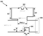
図6は、例示的なアンテナの波放射部分600を示す。図6の波放射部分600は、例示的なアンテナの例示的な波放射ダブレットを示す。より具体的には、図6は、例示的なDOEWG600の断面を示す。上記のように、DOEWG600は、水平フィード(すなわち、チャネル)、垂直フィード(すなわち、ダブレットネック)、および波指向部材604を含んでいてもよい。垂直フィードは、水平フィードからのエネルギーを2つの出力ポート602に結合するように構成されてもよく、その各々は、DOEWG600から電磁波の少なくとも一部を放射するように構成される。いくつかの実施形態では、入力ポートから最も遠いDOEWGは、位置606にバックストップを含んでいてもよい。バックストップは、それぞれの導波路の端または終端であり得る。最後のDOEWGの前に来るDOEWGは、単に位置606で開いてればよく、電磁波はその位置606を介して後続のDOEWGに伝播することができる。例えば、複数のDOEWGは、水平フィードが複数のDOEWGにわたって共通である場合、直列に接続してもよい。図6は、放射要素に結合する電磁信号の振幅および/または位相を修整ために調整できる様々なパラメータを示している。 FIG. 6 shows a
DOEWG600などのDOEWGを修整するために、垂直フィード幅、vfeed_a、およびステップ604の様々な寸法(例えば、dw、dx、およびdz1)を修整して、DOEWG600からの放射エネルギーの異なる割合を達成できる。ステップ604は、水平フィードを下って垂直フィードに伝播する電磁波の一部を反射するので、反射コンポーネントと称されることもある。さらに、いくつかの例では、反射コンポーネントの高さdz1は負であり得、すなわち、水平フィードの底より下に延在し得る。同様の修整メカニズムを使用して、寄生コンポーネントを修整することもできる。例えば、寄生コンポーネントは、垂直幅、および高さの様々な寸法(例えば、dw、dx、およびdz1)のいずれかを含んでいてもよい。 To modify a DOEWG such as
いくつかの例では、DOEWG600の各出力ポート602は、関連付けられた位相および振幅を有していてもよい。各出力ポート602について所望の位相および振幅を達成するためには、様々なジオメトリのコンポーネントを調整すればよい。前述のように、ステップ(反射コンポーネント)604は、垂直フィードを通して電磁波の一部を導くことができる。それぞれのDOEWG600の各出力ポート602に関連付けられた振幅を調整するために、各出力ポート602に関連付けられた高さを調整することができる。さらに、各出力ポート602に関連付けられる高さは、出力ポート602のこのフィードセクションの高さまたは深さでもよく、高さまたは深さの調整でよいだけでなく、一般に、これらの変化もしくはステップの多様性、または高さもしくは深さの増減でもよい。 In some examples, each
図6に示されるように、高さdz2および高さdz3は、2つの出力ポート602に関して振幅を制御するように調整してもよい。高さdz2と高さdz3を調整すると、ダブレットネックの物理的な寸法が変わる場合がある(図6の垂直フィードなど)。ダブレットネックは、高さdz2と高さdz3に基づいた寸法を有していてもよい。よって、高さdz2および高さdz3が様々なダブレットに対して変更されると、ダブレットネックの寸法(すなわち、ダブレットネックの少なくとも片側の高さ)が変化する可能性がある。一例では、高さdz2が高さdz3より大きいので、高さdz2に関連付けられた(すなわち、隣接して配置される)出力ポート602は、高さdz3に関連付けられた出力ポート602によって放射される信号の振幅よりも大きな振幅で放射し得る。 As shown in FIG. 6, height dz2 and height dz3 may be adjusted to control the amplitude for the two
図7は、レーダシステムで信号送信する方法700を示すフローチャートである。方法700は、上述の例示的なレーダユニットまたはシステムのいずれかを使用して実行してもよい。さらに、いくつかの実施形態では、方法700は、(放射ではなく)電磁波を受信するために疑似逆に実行することもできる。方法700は、例えば、自律車両に取り付けられたレーダシステムを使用して自律車両のナビゲーションを支援するために実行してもよい。上述のように、レーダユニットは、異なる配向を含む車両の様々な部分に取り付けることができる。例えば、レーダユニットは、レーダユニットの所望の性能に応じて、垂直、水平、直角、またはその他の異なる配向で車両に結合することができる。レーダユニットを車両に結合するには、様々なコンポーネントを使用することを伴う場合がある。他の例では、レーダユニットは車両コンポーネントの一部に組み込まれる場合もある。代替的に、無線通信技術を使用して通信するために方法700を実行してもよい。 FIG. 7 is a flowchart illustrating a
ブロック702では、方法700は、複数の送信アンテナを使用してレーダ信号を送信することを伴う。例えば、複数の送信アンテナは、4つの偏波のうちの1つで送信するように構成された送信アンテナを含むことができる。 At
一例として、送信アンテナは、3つの送信アンテナのセットを含んでいてもよい。第1の送信アンテナは、水平直線偏波で進行するレーダ信号を送信してもよく、第2の送信アンテナは、垂直直線偏波で進行するレーダ信号を送信してもよい。このセットは、水平面から約+45度の第1の傾斜偏波および水平面から約-45度の第2の傾斜偏波のような2つの偏波の間でレーダ信号を選択的に送信するように構成された第3の送信アンテナをさらに含んでいてもよい。 As an example, the transmit antennas may include a set of three transmit antennas. The first transmit antenna may transmit radar signals traveling with horizontal linear polarization, and the second transmit antenna may transmit radar signals traveling with vertical linear polarization. The set is adapted to selectively transmit radar signals between two polarizations, such as a first tilted polarization about +45 degrees from the horizontal and a second tilted polarization about -45 degrees from the horizontal. A configured third transmit antenna may also be included.
ブロック704では、方法700は、複数の受信アンテナを使用してレーダを受信することを含む。複数の受信アンテナは、4つの偏波のうちの1つで進行するレーダ信号を受信するように構成された送信アンテナを含むことができる。 At
いくつかの実施形態では、方法700は、少なくとも2つの偏波の間で選択的に送信された1つまたは複数のレーダ信号を受信することをさらに伴い得る。受信したレーダ信号を使用して、レーダシステムの環境の気象条件を判定できる。例えば、車両は、レーダシステムを使用して検出された気象条件に基づいてナビゲーション操作を実行してもよい。このように、車両制御システムは、気象条件が安全なナビゲーションにあまり適していない場合に制御戦略を調整してもよい。場合によっては、車両制御システムはレーダシステムを利用して、雨、雪、道路の水たまりの存在、またはナビゲーションに影響を与える可能性のあるその他の気象条件を検出できる。 In some embodiments,
さらなる実施形態では、方法700は、第1の偏波を有する第1のレーダ送信から受信した第1のレーダ反射送信に基づいて予備的な物体識別を判定することをさらに伴い得る。実施形態は、第1の偏波とは異なる第2の偏波を有する第2のレーダ信号の送信を引き起こし、第2のレーダ信号の送信から受信した第2の受信レーダ反射送信に基づいて物体識別を行うことをさらに伴ってもよい。 In a further embodiment,
いくつかの実施形態では、レーダシステムの送信アンテナは、複数の偏波の間で選択的にレーダ信号を送信してもよい。例えば、送信アンテナは、水平直線偏波と垂直直線偏波との間で選択的に送信してもよい。他の例では、送信アンテナは、水平面から約+45度の第1の傾斜偏波と、水平面から約-45度で放射するように構成された第2の傾斜偏波との間でレーダ信号を選択的に送信してもよい。 In some embodiments, a transmit antenna of a radar system may selectively transmit radar signals between multiple polarizations. For example, a transmit antenna may selectively transmit between horizontal linear polarization and vertical linear polarization. In another example, the transmit antenna steers the radar signal between a first tilted polarization at about +45 degrees from the horizontal and a second tilted polarization configured to radiate at about -45 degrees from the horizontal. It may be sent selectively.
さらなる例では、レーダシステムに関連付けられたプロセッサは、レーダ信号を使用して気象条件を判定してもよい。特に、プロセッサは、複数の偏波(例えば、少なくとも2つの偏波)のレーダに基づいて気象条件を判定してもよい。 In a further example, a processor associated with a radar system may use radar signals to determine weather conditions. In particular, the processor may determine weather conditions based on radar of multiple polarizations (eg, at least two polarizations).
導波路チャネル、導波路チャネルの部分、導波路チャネルの側面、波指向部材などの他の形状および寸法も可能であることを理解されたい。いくつかの実施形態では、導波路チャネルの矩形形状または角丸矩形形状は、製造するのに非常に便利であり得るが、同等またはそれ以上の利便性で導波路チャネルを製造するために既知またはまだ知られていない他の方法が実施されてもよい。 It should be understood that other shapes and dimensions of waveguide channels, portions of waveguide channels, sides of waveguide channels, wave directing members, etc. are possible. In some embodiments, a rectangular shape or rounded rectangular shape for the waveguide channel can be very convenient to manufacture, although there is no known or Other methods not yet known may be implemented.
さらに、図に示されている様々な要素は、他のレイアウト、配置、数量、または寸法も可能であることを理解されたい。例えば、アンテナまたはアンテナシステムの所与の用途が、図に示される偏波回転オーバーレイユニットセルの様々な機械加工部分、および/または本明細書に記載のアンテナ(複数可)およびアンテナシステム(複数可)のその他の機械加工された(または機械加工されていない)部分/コンポーネントの適切な大きさおよび寸法(例えば、チャネル寸法、金属層の厚さなど)を判定し得ることを理解されたい。例えば、上述のように、いくつかの例示的なレーダシステムは、77GHzの電磁波周波数で動作するように構成してもよく、これは、ミリメートル電磁波波長に対応する。この周波数では、装置のチャネル、ポートなどは、77GHzの周波数に適した所与の寸法のものでよい。他の例のアンテナおよびアンテナアプリケーションも可能である。 Further, it should be understood that other layouts, arrangements, quantities or dimensions of the various elements shown in the figures are possible. For example, a given application of an antenna or antenna system may include various machined portions of the polarization rotating overlay unit cell shown in the figures, and/or the antenna(s) and antenna system(s) described herein. ) may be determined for other machined (or non-machined) portions/components (e.g., channel dimensions, metal layer thicknesses, etc.). For example, as noted above, some exemplary radar systems may be configured to operate at an electromagnetic frequency of 77 GHz, which corresponds to millimeter electromagnetic wavelengths. At this frequency, the channels, ports, etc. of the device may be of given dimensions suitable for the 77 GHz frequency. Other example antennas and antenna applications are also possible.
さらに、「アンテナ」という語は、電磁スペクトルの無線周波数内のみの電磁波を伴う用途に限定されるべきではない。「アンテナ」という用語は、本明細書では、電磁波を送信および/または受信することができるデバイスを説明するために広く使用している。例えば、本明細書に記載されているアンテナまたはアンテナのコンポーネントのいずれも、光を送信および/または受信することが可能であり得る。さらに、本明細書で説明するアンテナまたはアンテナのコンポーネントのいずれも、光源(例えば、光ファイバまたは光レーザ)によって給電することが可能であり得る。かかる例示的なアンテナは、例えば、コンピューティングデバイス内の光相互接続として使用してもよい。さらに、そのようなアンテナ内のコンポーネントの対応する形状と寸法は、波長に応じて変えてもよい(例えば、光学の実施形態で使用されるコンポーネントは、無線の実施形態のミリメートルの形状とは対照的に、数百ナノメートルの縮尺の形状を有し得る)。 Furthermore, the term "antenna" should not be limited to applications involving electromagnetic waves only within the radio frequencies of the electromagnetic spectrum. The term "antenna" is used broadly herein to describe a device capable of transmitting and/or receiving electromagnetic waves. For example, any of the antennas or components of antennas described herein may be capable of transmitting and/or receiving light. Additionally, any of the antennas or components of antennas described herein may be capable of being powered by a light source such as an optical fiber or optical laser. Such exemplary antennas may be used as optical interconnects within computing devices, for example. Additionally, the corresponding shapes and dimensions of components within such antennas may vary with wavelength (e.g., components used in optical embodiments may have millimeter shapes as opposed to wireless embodiments). can typically have features on the scale of hundreds of nanometers).
本明細書において説明される配置は、例示のみを目的としていることを理解されたい。このようなことから、当業者であれば、他の配置および他の要素(例えば、機械、装置、インターフェース、機能、順序、および機能のグループ化など)が代わりに使用でき、いくつかの要素は、所望の結果に応じて一括して省略してもよいことを理解するであろう。さらに、説明される要素の多くは、個別のコンポーネントもしくは分散したコンポーネントとして、または他のコンポーネントと共に、任意の適切な組み合わせおよび場所で実装してもよい。 It should be understood that the arrangements described herein are for illustrative purposes only. As such, other arrangements and other elements (e.g., machines, devices, interfaces, functions, sequences, groupings of functions, etc.) can be substituted by those skilled in the art, and some elements are , may be omitted altogether depending on the desired result. Moreover, many of the described elements may be implemented as separate or distributed components, or with other components, in any suitable combination and location.
様々な態様および実施形態が本明細書において開示されているが、当業者には、その他の態様および実施形態が明らかとなるであろう。本明細書に開示される様々な態様および実施形態は、例証を目的とするものであり、限定することを意図するものではなく、その範囲は、以下の特許請求の範囲によって示される。 While various aspects and embodiments are disclosed herein, other aspects and embodiments will be apparent to those skilled in the art. The various aspects and embodiments disclosed herein are intended to be illustrative and not limiting, the scope of which is indicated by the following claims.
Claims (20)
Translated fromJapanese複数の送信アンテナであって、第1の偏波を有するレーダ信号を送信するように構成されている第1の送信アンテナ、第2の偏波を有するレーダ信号を送信するように構成されている第2の送信アンテナ、および第3の偏波と第4の偏波との間でレーダ信号を選択的に送信するように構成されている第3の送信アンテナを含み、前記第1の偏波、前記第2の偏波、前記第3の偏波、および前記第4の偏波は互いに異なる、複数の送信アンテナと、
複数の受信アンテナであって、前記第1の偏波、前記第2の偏波、前記第3の偏波および前記第4の偏波のうちの少なくとも1つからレーダ信号の反射を受信するように構成されているそれぞれの受信アンテナを含む、複数の受信アンテナと、を備えるレーダユニット。a radar unit,
A plurality of transmit antennas, a first transmit antenna configured to transmit radar signals having a first polarization, and a radar signal having a second polarization. a second transmit antenna and a third transmit antenna configured toselectively transmit radar signalsbetween a third polarization and a fourth polarization; , a plurality of transmit antennas, wherein the second polarization, the third polarization, and the fourth polarization are different from each other;
a plurality of receive antennas for receiving radar signal reflections from at least one of the first polarization, the second polarization, the third polarizationand the fourth polarization; a plurality of receive antennas, each receive antenna configured to:
前記第1の送信アンテナは、前記第1の導波路チャネルからの電磁エネルギーを使用してレーダ信号を送信するように構成され、前記第2の送信アンテナは、前記第2の導波路チャネルからの電磁エネルギーを使用してレーダ信号を送信するように構成され、前記第3の送信アンテナは、前記第3の導波路チャネルからの電磁エネルギーを使用してレーダ信号を送信するように構成されている、請求項1に記載のレーダユニット。further comprising a plurality of waveguide channels, including at least a first waveguide channel, a second waveguide channel and a third waveguide channel;
The first transmit antenna is configured to transmit radar signals using electromagnetic energy from the first waveguide channel, and the second transmit antenna is configured to transmit radar signals from the second waveguide channel. configured to transmit radar signals using electromagnetic energy, the third transmitting antenna configured to transmit radar signals using electromagnetic energy from the third waveguide channel A radar unit according to claim 1.
前記第1の偏波を有する第1のレーダ送信信号から受信した第1のレーダ反射送信に基づいて予備的な物体識別を判定し、
前記第2の偏波を有する第2のレーダ信号を送信させ、
前記第2のレーダ信号の前記送信から受信した第2の受信レーダ反射送信に基づいて物体識別を行うように構成されている、請求項10に記載のレーダユニット。further comprising a processor, said processor comprising:
determining a preliminary object identification based on a first radar return transmission received from the first radar transmission signal having the first polarization;
transmit a second radar signal having the second polarization;
11. The radar unit of claim 10, configured to perform object identification based on a second received radar return transmission received from said transmission of said second radar signal.
前記レーダユニットの第1の送信アンテナによって、第1の偏波を有するレーダ信号を送信することと、
前記レーダユニットの第2の送信アンテナによって、第2の偏波を有するレーダ信号を送信することと、
前記レーダユニットの第3の送信アンテナによって、第3の偏波と第4の偏波との間でレーダ信号を選択的に送信することと、
複数の受信アンテナを使用して前記レーダ信号の反射を受信することであって、前記複数の受信アンテナは、前記第1の偏波、前記第2の偏波、前記第3の偏波および前記第4の偏波のうちの少なくとも1つからレーダ信号を受信するように構成されているそれぞれの受信アンテナを含む、受信することと、を含み、前記第1の偏波、前記第2の偏波、前記第3の偏波および前記第4の偏波は互いに異なる、方法。A method of signal transmission using a radar unit, comprising:
transmitting a radar signal having a first polarization by a first transmit antenna of the radar unit;
transmitting a radar signal having a second polarization by a second transmit antenna of the radar unit;
selectively transmitting a radar signal between a third polarizationand a fourth polarization by a third transmit antenna of the radar unit;
receiving reflections of the radar signal using a plurality of receive antennas, the plurality of receive antennas having the first polarization, the second polarization, the third polarizationand the and receiving, including respective receive antennas configured to receive radar signals from at least one ofa fourth polarization , the first polarization, the second polarization. The method, wherein the waves, said third polarizationand said fourth polarization are different from each other.
前記第2の偏波を有する第2のレーダ信号を送信させることと、
前記第2のレーダ信号の前記送信から受信した第2の受信レーダ反射送信に基づいて物体識別を行うことと、をさらに含む請求項14に記載の方法。determining a preliminary object identification based on a first radar return transmission received from the first radar transmission signal having the first polarization;
transmitting a second radar signal having the second polarization;
15. The method of claim14 , further comprising performing object identification based on a second received radar return transmission received from said transmission of said second radar signal.
複数の送信アンテナであって、水平直線偏波で送信するように構成されている第1の送信アンテナと、垂直水平直線偏波で送信するように構成されている第2の送信アンテナと、水平面から約+45度の第1の傾斜偏波と前記水平面から約-45度で放射するように構成されている第2の傾斜偏波との間で選択的に送信するように構成されている第3の送信アンテナとを含む、複数の送信アンテナと、
複数の受信アンテナであって、前記水平直線偏波で送信されたレーダ信号の反射を受信するように構成されている第1の受信アンテナと、前記垂直水平直線偏波で送信されたレーダ信号の反射を受信するように構成されている第2の受信アンテナと、前記第1の傾斜偏波で送信されたレーダ信号の反射を受信するように構成されている第3の受信アンテナと、前記第2の傾斜偏波で送信されたレーダ信号の反射を受信するように構成されている
第4の受信アンテナとを含む、複数の受信アンテナと、を備える、レーダシステム。a radar system,
a plurality of transmit antennas, a first transmit antenna configured to transmit with horizontal linear polarization, a second transmit antenna configured to transmit with vertical horizontal linear polarization, and a horizontal plane and a second tilted polarization configured to radiate at about -45 degrees from the horizontal plane. a plurality of transmit antennas, including 3 transmit antennas;
a plurality of receiving antennas, a first receiving antenna configured to receive reflections of radar signals transmitted with the horizontal linear polarization; a second receive antenna configured to receive reflections; a third receive antenna configured to receive reflections of a radar signal transmitted with said first tilted polarization; a plurality of receive antennas, including a fourth receive antenna configured to receive reflections of radar signals transmitted with two tilted polarizations.
Applications Claiming Priority (3)
| Application Number | Priority Date | Filing Date | Title |
|---|---|---|---|
| US15/848,205 | 2017-12-20 | ||
| US15/848,205US10852390B2 (en) | 2017-12-20 | 2017-12-20 | Multiple polarization radar unit |
| PCT/US2018/062249WO2019125697A1 (en) | 2017-12-20 | 2018-11-21 | Multiple polarization radar unit |
Publications (2)
| Publication Number | Publication Date |
|---|---|
| JP2021507219A JP2021507219A (en) | 2021-02-22 |
| JP7271550B2true JP7271550B2 (en) | 2023-05-11 |
Family
ID=66815928
Family Applications (1)
| Application Number | Title | Priority Date | Filing Date |
|---|---|---|---|
| JP2020532686AActiveJP7271550B2 (en) | 2017-12-20 | 2018-11-21 | Multiple polarization radar unit |
Country Status (6)
| Country | Link |
|---|---|
| US (2) | US10852390B2 (en) |
| EP (1) | EP3717930A4 (en) |
| JP (1) | JP7271550B2 (en) |
| KR (1) | KR102401038B1 (en) |
| CN (1) | CN111480090A (en) |
| WO (1) | WO2019125697A1 (en) |
Families Citing this family (34)
| Publication number | Priority date | Publication date | Assignee | Title |
|---|---|---|---|---|
| US20220200115A1 (en)* | 2020-12-18 | 2022-06-23 | Aptiv Technologies Limited | Waveguide with slot-fed dipole elements |
| WO2019198420A1 (en)* | 2018-04-11 | 2019-10-17 | ソニー株式会社 | Radar device, radar control device, and radar system |
| CN112424629B (en)* | 2018-06-26 | 2024-04-09 | 苏州宝时得电动工具有限公司 | Electric device using radar |
| DE102019124507A1 (en) | 2018-09-13 | 2020-03-19 | Magna Closures Inc. | CIRCULAR POLARIZED MOTOR VEHICLE RADAR FOR IMPROVED SIGNAL-NOISE RATIO |
| EP3859388A4 (en)* | 2018-09-27 | 2022-06-15 | Kyocera Corporation | Electronic device, control method for electronic device, and control program for electronic device |
| US10811778B2 (en)* | 2018-12-21 | 2020-10-20 | Waymo Llc | Center fed open ended waveguide (OEWG) antenna arrays |
| JP7174668B2 (en)* | 2019-04-25 | 2022-11-17 | 京セラ株式会社 | ELECTRONIC DEVICE, ELECTRONIC DEVICE CONTROL METHOD, AND ELECTRONIC DEVICE CONTROL PROGRAM |
| US11114733B2 (en)* | 2019-07-23 | 2021-09-07 | Veoneer Us, Inc. | Waveguide interconnect transitions and related sensor assemblies |
| US11365801B2 (en)* | 2019-08-28 | 2022-06-21 | Donovan Knutson | Utility vehicle having adaptive drive limiting control |
| US11275174B2 (en) | 2019-08-28 | 2022-03-15 | Waymo Llc | Methods and systems for reducing vehicle sensor interference |
| JP2021076443A (en)* | 2019-11-07 | 2021-05-20 | 株式会社デンソー | Vehicle radar system |
| US11349220B2 (en)* | 2020-02-12 | 2022-05-31 | Veoneer Us, Inc. | Oscillating waveguides and related sensor assemblies |
| US11378683B2 (en)* | 2020-02-12 | 2022-07-05 | Veoneer Us, Inc. | Vehicle radar sensor assemblies |
| US11860294B2 (en)* | 2020-08-24 | 2024-01-02 | Google Llc | Electromagnetic vector sensors for a smart-device-based radar system |
| WO2022096779A1 (en)* | 2020-11-06 | 2022-05-12 | Nokia Technologies Oy | Proximity detection for a beamforming transceiver |
| EP4001953A1 (en)* | 2020-11-11 | 2022-05-25 | Aptiv Technologies Limited | Automotive radar system |
| CN112578339B (en)* | 2020-12-02 | 2024-02-13 | 云南航天工程物探检测股份有限公司 | A multi-polarization mode combination array ground-penetrating radar antenna and its control method |
| US20230420857A1 (en)* | 2020-12-08 | 2023-12-28 | Huber+Suhner Ag | Antenna device |
| US11749883B2 (en) | 2020-12-18 | 2023-09-05 | Aptiv Technologies Limited | Waveguide with radiation slots and parasitic elements for asymmetrical coverage |
| US11901601B2 (en) | 2020-12-18 | 2024-02-13 | Aptiv Technologies Limited | Waveguide with a zigzag for suppressing grating lobes |
| US11668787B2 (en)* | 2021-01-29 | 2023-06-06 | Aptiv Technologies Limited | Waveguide with lobe suppression |
| US12058804B2 (en) | 2021-02-09 | 2024-08-06 | Aptiv Technologies AG | Formed waveguide antennas of a radar assembly |
| US11721905B2 (en) | 2021-03-16 | 2023-08-08 | Aptiv Technologies Limited | Waveguide with a beam-forming feature with radiation slots |
| US11962085B2 (en) | 2021-05-13 | 2024-04-16 | Aptiv Technologies AG | Two-part folded waveguide having a sinusoidal shape channel including horn shape radiating slots formed therein which are spaced apart by one-half wavelength |
| DE102021207896A1 (en)* | 2021-07-22 | 2023-01-26 | Robert Bosch Gesellschaft mit beschränkter Haftung | Radar sensor with waveguide structure |
| KR102416476B1 (en)* | 2021-07-28 | 2022-07-05 | 주식회사 에이티코디 | Radar module using multi polarization |
| US11616282B2 (en) | 2021-08-03 | 2023-03-28 | Aptiv Technologies Limited | Transition between a single-ended port and differential ports having stubs that match with input impedances of the single-ended and differential ports |
| EP4454064A1 (en)* | 2021-12-23 | 2024-10-30 | Huber+Suhner AG | Antenna device |
| CN114665284A (en)* | 2022-03-22 | 2022-06-24 | 东南大学 | A millimeter wave array antenna |
| EP4249943B1 (en) | 2022-03-25 | 2025-07-16 | Rohde & Schwarz GmbH & Co. KG | Radar test system |
| US12210115B2 (en)* | 2022-04-05 | 2025-01-28 | Honeywell International Inc. | High isolation between transmit and receive antenna in FMCW radars |
| US20230417904A1 (en)* | 2022-06-28 | 2023-12-28 | Veoneer Us, Llc | Integrated circuit to waveguide transitional structures and related sensor assemblies |
| US12148992B2 (en) | 2023-01-25 | 2024-11-19 | Aptiv Technologies AG | Hybrid horn waveguide antenna |
| FR3147022B1 (en)* | 2023-03-22 | 2025-02-07 | Vitesco Technologies | Improved sensitivity gesture detection system for a motor vehicle |
Citations (4)
| Publication number | Priority date | Publication date | Assignee | Title |
|---|---|---|---|---|
| JP2010014533A (en) | 2008-07-03 | 2010-01-21 | Toyota Central R&D Labs Inc | Polarization radar device |
| JP2015190809A (en) | 2014-03-27 | 2015-11-02 | 日本電産エレシス株式会社 | Radar apparatus and radar method |
| JP2016516983A (en) | 2013-03-11 | 2016-06-09 | トルンマー,シュテファン | Polarization radar for object classification and its proper use |
| US20170353338A1 (en) | 2016-06-06 | 2017-12-07 | Intel Corporation | Phased array antenna cell with adaptive quad polarization |
Family Cites Families (45)
| Publication number | Priority date | Publication date | Assignee | Title |
|---|---|---|---|---|
| US3568190A (en)* | 1968-07-26 | 1971-03-02 | North American Rockwell | Full monopulse variable polarization feed bridge |
| FR2108814B1 (en)* | 1970-10-08 | 1976-09-03 | Labo Cent Telecommunicat | |
| US4197541A (en)* | 1977-12-19 | 1980-04-08 | International Telephone And Telegraph Corporation | Polarization agile planar array |
| US5038150A (en)* | 1990-05-14 | 1991-08-06 | Hughes Aircraft Company | Feed network for a dual circular and dual linear polarization antenna |
| JPH04122874A (en)* | 1990-09-14 | 1992-04-23 | Nec Corp | Radar apparatus |
| US5329285A (en)* | 1991-07-18 | 1994-07-12 | The Boeing Company | Dually polarized monopulse feed using an orthogonal polarization coupler in a multimode waveguide |
| FR2699008B1 (en)* | 1992-12-04 | 1994-12-30 | Alcatel Espace | Active antenna with variable polarization synthesis. |
| US5337058A (en)* | 1993-04-16 | 1994-08-09 | United Technologies Corporation | Fast switching polarization diverse radar antenna system |
| JPH07191132A (en)* | 1993-12-24 | 1995-07-28 | Nippondenso Co Ltd | On-vehicle radar device |
| JPH08194055A (en)* | 1995-01-17 | 1996-07-30 | Mitsubishi Electric Corp | Polarization control radar device |
| EP0995128A1 (en)* | 1997-07-02 | 2000-04-26 | Ekko Dane Production A/S | Radar plant and measurement technique for determination of the orientation and the depth of buried objects |
| US6201508B1 (en)* | 1999-12-13 | 2001-03-13 | Space Systems/Loral, Inc. | Injection-molded phased array antenna system |
| US6731241B2 (en)* | 2001-06-13 | 2004-05-04 | Raytheon Company | Dual-polarization common aperture antenna with rectangular wave-guide fed centered longitudinal slot array and micro-stripline fed air cavity back transverse series slot array |
| US6545647B1 (en)* | 2001-07-13 | 2003-04-08 | Hrl Laboratories, Llc | Antenna system for communicating simultaneously with a satellite and a terrestrial system |
| US6724341B1 (en)* | 2002-01-07 | 2004-04-20 | The United States Of America As Represented By The Secretary Of The Army | Autonomous onboard absolute position and orientation referencing system |
| US20070241962A1 (en)* | 2003-11-14 | 2007-10-18 | Hiroshi Shinoda | Automotive Radar |
| DE102006029317A1 (en)* | 2006-06-23 | 2007-12-27 | Selex Sistemi Integrati Gmbh | Polarization modulated transmitter |
| JP5040549B2 (en)* | 2007-09-20 | 2012-10-03 | 日本電気株式会社 | Synthetic aperture radar, compact polarimetry SAR processing method, program |
| US8830133B2 (en)* | 2008-02-04 | 2014-09-09 | Commonwealth Scientific And Industrial Research Organisation | Circularly polarised array antenna |
| US7733265B2 (en)* | 2008-04-04 | 2010-06-08 | Toyota Motor Engineering & Manufacturing North America, Inc. | Three dimensional integrated automotive radars and methods of manufacturing the same |
| US7834803B2 (en)* | 2008-09-03 | 2010-11-16 | Lockheed Martin Corporation | Electronically steered, dual-polarized, dual-plane, monopulse antenna feed |
| US8098189B1 (en)* | 2008-09-23 | 2012-01-17 | Rockwell Collins, Inc. | Weather radar system and method using dual polarization antenna |
| GB0916300D0 (en)* | 2009-09-17 | 2009-10-28 | Univ Manchester Metropolitan | Remote detection of bladed objects |
| JP5135317B2 (en)* | 2009-11-04 | 2013-02-06 | 株式会社ホンダエレシス | On-vehicle radar device and program |
| JP5558943B2 (en)* | 2010-07-06 | 2014-07-23 | 古野電気株式会社 | Slot array antenna and radar device |
| US8902103B2 (en)* | 2011-03-16 | 2014-12-02 | Electronics And Telecommunications Research Institute | Radar apparatus supporting short and long range radar operation |
| JP2013224893A (en)* | 2012-04-23 | 2013-10-31 | Honda Elesys Co Ltd | Direction detection device, direction detection method, and direction detection program |
| US9103906B2 (en) | 2012-06-25 | 2015-08-11 | Mando Corporation | Radar apparatus utilizing multiple transmission channels |
| US9391375B1 (en)* | 2013-09-27 | 2016-07-12 | The United States Of America As Represented By The Secretary Of The Navy | Wideband planar reconfigurable polarization antenna array |
| US20160047907A1 (en)* | 2014-08-14 | 2016-02-18 | Google Inc. | Modular Planar Multi-Sector 90 Degrees FOV Radar Antenna Architecture |
| US9612317B2 (en)* | 2014-08-17 | 2017-04-04 | Google Inc. | Beam forming network for feeding short wall slotted waveguide arrays |
| US10281571B2 (en) | 2014-08-21 | 2019-05-07 | Raytheon Company | Phased array antenna using stacked beams in elevation and azimuth |
| WO2016098913A1 (en) | 2014-12-15 | 2016-06-23 | 우리로광통신 주식회사 | Vehicle radar |
| CN104518289A (en)* | 2014-12-22 | 2015-04-15 | 中国电子科技集团公司第三十八研究所 | Dual-polarized slotted waveguide antenna array |
| US9851436B2 (en)* | 2015-01-05 | 2017-12-26 | Delphi Technologies, Inc. | Radar antenna assembly with panoramic detection |
| US20160195607A1 (en)* | 2015-01-06 | 2016-07-07 | Radar Obstacle Detection Ltd. | Short-ragne obstacle detection radar using stepped frequency pulse train |
| US20180066991A1 (en)* | 2015-03-12 | 2018-03-08 | President And Fellows Of Harvard College | Polarization-selective scattering antenna arrays based polarimeter |
| US10514341B2 (en)* | 2015-03-24 | 2019-12-24 | Utilis Israel Ltd. | System and method of detecting underground gas leakage |
| US10809375B1 (en)* | 2015-09-14 | 2020-10-20 | Rockwell Collins, Inc. | Radar system and method for detecting hazards associated with particles or bodies |
| KR101698030B1 (en)* | 2015-10-01 | 2017-01-19 | 현대자동차주식회사 | antenna |
| KR102660419B1 (en)* | 2016-04-19 | 2024-04-24 | 주식회사 에이치엘클레무브 | Radar device |
| US10008782B2 (en)* | 2016-06-24 | 2018-06-26 | Huawei Technologies Co., Ltd. | Low coupling full-duplex MIMO antenna array with coupled signal cancelling |
| US10756417B2 (en)* | 2017-12-14 | 2020-08-25 | Waymo Llc | Adaptive polarimetric radar architecture for autonomous driving |
| JP7174668B2 (en)* | 2019-04-25 | 2022-11-17 | 京セラ株式会社 | ELECTRONIC DEVICE, ELECTRONIC DEVICE CONTROL METHOD, AND ELECTRONIC DEVICE CONTROL PROGRAM |
| US11616309B2 (en)* | 2019-11-20 | 2023-03-28 | Thinkom Solutions, Inc. | Wide-scan-capable polarization-diverse polarizer with enhanced switchable dual-polarization properties |
- 2017
- 2017-12-20USUS15/848,205patent/US10852390B2/ennot_activeExpired - Fee Related
- 2018
- 2018-11-21WOPCT/US2018/062249patent/WO2019125697A1/ennot_activeCeased
- 2018-11-21KRKR1020207019915Apatent/KR102401038B1/enactiveActive
- 2018-11-21JPJP2020532686Apatent/JP7271550B2/enactiveActive
- 2018-11-21CNCN201880081077.2Apatent/CN111480090A/enactivePending
- 2018-11-21EPEP18892586.1Apatent/EP3717930A4/ennot_activeWithdrawn
- 2020
- 2020-11-18USUS16/951,574patent/US11644533B2/enactiveActive
Patent Citations (4)
| Publication number | Priority date | Publication date | Assignee | Title |
|---|---|---|---|---|
| JP2010014533A (en) | 2008-07-03 | 2010-01-21 | Toyota Central R&D Labs Inc | Polarization radar device |
| JP2016516983A (en) | 2013-03-11 | 2016-06-09 | トルンマー,シュテファン | Polarization radar for object classification and its proper use |
| JP2015190809A (en) | 2014-03-27 | 2015-11-02 | 日本電産エレシス株式会社 | Radar apparatus and radar method |
| US20170353338A1 (en) | 2016-06-06 | 2017-12-07 | Intel Corporation | Phased array antenna cell with adaptive quad polarization |
Also Published As
| Publication number | Publication date |
|---|---|
| JP2021507219A (en) | 2021-02-22 |
| US20190187247A1 (en) | 2019-06-20 |
| WO2019125697A1 (en) | 2019-06-27 |
| US11644533B2 (en) | 2023-05-09 |
| US20210072344A1 (en) | 2021-03-11 |
| CN111480090A (en) | 2020-07-31 |
| EP3717930A1 (en) | 2020-10-07 |
| EP3717930A4 (en) | 2021-06-30 |
| US10852390B2 (en) | 2020-12-01 |
| KR20200086753A (en) | 2020-07-17 |
| KR102401038B1 (en) | 2022-05-24 |
Similar Documents
| Publication | Publication Date | Title |
|---|---|---|
| JP7271550B2 (en) | Multiple polarization radar unit | |
| US20210367352A1 (en) | Radar antenna array with parasitic elements excited by surface waves | |
| US11619734B2 (en) | Integrated MIMO and SAR radar antenna architecture | |
| US10826166B2 (en) | Plated, injection molded, automotive radar waveguide antenna | |
| US11749883B2 (en) | Waveguide with radiation slots and parasitic elements for asymmetrical coverage | |
| US11309636B2 (en) | Antenna structure for reducing beam squint and sidelobes |
Legal Events
| Date | Code | Title | Description |
|---|---|---|---|
| A621 | Written request for application examination | Free format text:JAPANESE INTERMEDIATE CODE: A621 Effective date:20200730 | |
| A977 | Report on retrieval | Free format text:JAPANESE INTERMEDIATE CODE: A971007 Effective date:20210630 | |
| A131 | Notification of reasons for refusal | Free format text:JAPANESE INTERMEDIATE CODE: A131 Effective date:20210824 | |
| A521 | Request for written amendment filed | Free format text:JAPANESE INTERMEDIATE CODE: A523 Effective date:20211115 | |
| A131 | Notification of reasons for refusal | Free format text:JAPANESE INTERMEDIATE CODE: A131 Effective date:20220329 | |
| A521 | Request for written amendment filed | Free format text:JAPANESE INTERMEDIATE CODE: A523 Effective date:20220602 | |
| A131 | Notification of reasons for refusal | Free format text:JAPANESE INTERMEDIATE CODE: A131 Effective date:20220830 | |
| A521 | Request for written amendment filed | Free format text:JAPANESE INTERMEDIATE CODE: A523 Effective date:20221128 | |
| TRDD | Decision of grant or rejection written | ||
| A01 | Written decision to grant a patent or to grant a registration (utility model) | Free format text:JAPANESE INTERMEDIATE CODE: A01 Effective date:20230324 | |
| A601 | Written request for extension of time | Free format text:JAPANESE INTERMEDIATE CODE: A601 Effective date:20230421 | |
| A61 | First payment of annual fees (during grant procedure) | Free format text:JAPANESE INTERMEDIATE CODE: A61 Effective date:20230426 | |
| R150 | Certificate of patent or registration of utility model | Ref document number:7271550 Country of ref document:JP Free format text:JAPANESE INTERMEDIATE CODE: R150 |