JP7270826B2 - Airbag device and vehicle seat - Google Patents
Airbag device and vehicle seatDownload PDFInfo
- Publication number
- JP7270826B2 JP7270826B2JP2022500296AJP2022500296AJP7270826B2JP 7270826 B2JP7270826 B2JP 7270826B2JP 2022500296 AJP2022500296 AJP 2022500296AJP 2022500296 AJP2022500296 AJP 2022500296AJP 7270826 B2JP7270826 B2JP 7270826B2
- Authority
- JP
- Japan
- Prior art keywords
- airbag device
- seat
- airbag
- seat frame
- occupant
- Prior art date
- Legal status (The legal status is an assumption and is not a legal conclusion. Google has not performed a legal analysis and makes no representation as to the accuracy of the status listed.)
- Active
Links
Images


Classifications
- B—PERFORMING OPERATIONS; TRANSPORTING
- B60—VEHICLES IN GENERAL
- B60R—VEHICLES, VEHICLE FITTINGS, OR VEHICLE PARTS, NOT OTHERWISE PROVIDED FOR
- B60R21/00—Arrangements or fittings on vehicles for protecting or preventing injuries to occupants or pedestrians in case of accidents or other traffic risks
- B60R21/02—Occupant safety arrangements or fittings, e.g. crash pads
- B60R21/16—Inflatable occupant restraints or confinements designed to inflate upon impact or impending impact, e.g. air bags
- B60R21/20—Arrangements for storing inflatable members in their non-use or deflated condition; Arrangement or mounting of air bag modules or components
- B60R21/207—Arrangements for storing inflatable members in their non-use or deflated condition; Arrangement or mounting of air bag modules or components in vehicle seats
- B—PERFORMING OPERATIONS; TRANSPORTING
- B60—VEHICLES IN GENERAL
- B60R—VEHICLES, VEHICLE FITTINGS, OR VEHICLE PARTS, NOT OTHERWISE PROVIDED FOR
- B60R21/00—Arrangements or fittings on vehicles for protecting or preventing injuries to occupants or pedestrians in case of accidents or other traffic risks
- B60R21/02—Occupant safety arrangements or fittings, e.g. crash pads
- B60R21/16—Inflatable occupant restraints or confinements designed to inflate upon impact or impending impact, e.g. air bags
- B60R21/23—Inflatable members
- B60R21/231—Inflatable members characterised by their shape, construction or spatial configuration
- B60R21/23138—Inflatable members characterised by their shape, construction or spatial configuration specially adapted for side protection
- B—PERFORMING OPERATIONS; TRANSPORTING
- B60—VEHICLES IN GENERAL
- B60R—VEHICLES, VEHICLE FITTINGS, OR VEHICLE PARTS, NOT OTHERWISE PROVIDED FOR
- B60R21/00—Arrangements or fittings on vehicles for protecting or preventing injuries to occupants or pedestrians in case of accidents or other traffic risks
- B60R21/02—Occupant safety arrangements or fittings, e.g. crash pads
- B60R21/16—Inflatable occupant restraints or confinements designed to inflate upon impact or impending impact, e.g. air bags
- B60R21/23—Inflatable members
- B60R21/231—Inflatable members characterised by their shape, construction or spatial configuration
- B60R21/233—Inflatable members characterised by their shape, construction or spatial configuration comprising a plurality of individual compartments; comprising two or more bag-like members, one within the other
- B—PERFORMING OPERATIONS; TRANSPORTING
- B60—VEHICLES IN GENERAL
- B60R—VEHICLES, VEHICLE FITTINGS, OR VEHICLE PARTS, NOT OTHERWISE PROVIDED FOR
- B60R21/00—Arrangements or fittings on vehicles for protecting or preventing injuries to occupants or pedestrians in case of accidents or other traffic risks
- B60R2021/003—Arrangements or fittings on vehicles for protecting or preventing injuries to occupants or pedestrians in case of accidents or other traffic risks characterised by occupant or pedestian
- B60R2021/0039—Body parts of the occupant or pedestrian affected by the accident
- B60R2021/0044—Chest
- B—PERFORMING OPERATIONS; TRANSPORTING
- B60—VEHICLES IN GENERAL
- B60R—VEHICLES, VEHICLE FITTINGS, OR VEHICLE PARTS, NOT OTHERWISE PROVIDED FOR
- B60R21/00—Arrangements or fittings on vehicles for protecting or preventing injuries to occupants or pedestrians in case of accidents or other traffic risks
- B60R2021/003—Arrangements or fittings on vehicles for protecting or preventing injuries to occupants or pedestrians in case of accidents or other traffic risks characterised by occupant or pedestian
- B60R2021/0039—Body parts of the occupant or pedestrian affected by the accident
- B60R2021/0048—Head
- B—PERFORMING OPERATIONS; TRANSPORTING
- B60—VEHICLES IN GENERAL
- B60R—VEHICLES, VEHICLE FITTINGS, OR VEHICLE PARTS, NOT OTHERWISE PROVIDED FOR
- B60R21/00—Arrangements or fittings on vehicles for protecting or preventing injuries to occupants or pedestrians in case of accidents or other traffic risks
- B60R21/02—Occupant safety arrangements or fittings, e.g. crash pads
- B60R21/16—Inflatable occupant restraints or confinements designed to inflate upon impact or impending impact, e.g. air bags
- B60R21/23—Inflatable members
- B60R21/231—Inflatable members characterised by their shape, construction or spatial configuration
- B60R21/23138—Inflatable members characterised by their shape, construction or spatial configuration specially adapted for side protection
- B60R2021/23146—Inflatable members characterised by their shape, construction or spatial configuration specially adapted for side protection seat mounted
- B—PERFORMING OPERATIONS; TRANSPORTING
- B60—VEHICLES IN GENERAL
- B60R—VEHICLES, VEHICLE FITTINGS, OR VEHICLE PARTS, NOT OTHERWISE PROVIDED FOR
- B60R21/00—Arrangements or fittings on vehicles for protecting or preventing injuries to occupants or pedestrians in case of accidents or other traffic risks
- B60R21/02—Occupant safety arrangements or fittings, e.g. crash pads
- B60R21/16—Inflatable occupant restraints or confinements designed to inflate upon impact or impending impact, e.g. air bags
- B60R21/23—Inflatable members
- B60R21/231—Inflatable members characterised by their shape, construction or spatial configuration
- B60R2021/23161—Inflatable members characterised by their shape, construction or spatial configuration specially adapted for protecting at least two passengers, e.g. preventing them from hitting each other
- B—PERFORMING OPERATIONS; TRANSPORTING
- B60—VEHICLES IN GENERAL
- B60R—VEHICLES, VEHICLE FITTINGS, OR VEHICLE PARTS, NOT OTHERWISE PROVIDED FOR
- B60R21/00—Arrangements or fittings on vehicles for protecting or preventing injuries to occupants or pedestrians in case of accidents or other traffic risks
- B60R21/02—Occupant safety arrangements or fittings, e.g. crash pads
- B60R21/16—Inflatable occupant restraints or confinements designed to inflate upon impact or impending impact, e.g. air bags
- B60R21/23—Inflatable members
- B60R21/231—Inflatable members characterised by their shape, construction or spatial configuration
- B60R21/233—Inflatable members characterised by their shape, construction or spatial configuration comprising a plurality of individual compartments; comprising two or more bag-like members, one within the other
- B60R2021/23308—Inflatable members characterised by their shape, construction or spatial configuration comprising a plurality of individual compartments; comprising two or more bag-like members, one within the other the individual compartments defining the external shape of the bag
Landscapes
- Engineering & Computer Science (AREA)
- Mechanical Engineering (AREA)
- Air Bags (AREA)
- Vehicle Waterproofing, Decoration, And Sanitation Devices (AREA)
- Seats For Vehicles (AREA)
Description
Translated fromJapanese本発明は、車両用シート及び当該シートに装備されるエアバッグ装置に関する。特に、座席に着座した乗員の姿勢に関わらず、当該乗員を確実に拘束可能なエアバッグ装置に関する。 The present invention relates to a vehicle seat and an airbag device installed in the seat. In particular, the present invention relates to an airbag device capable of reliably restraining an occupant regardless of the posture of the occupant seated on the seat.
車両の事故発生時に乗員を保護するために1つまたは複数のエアバッグを車両に設けることは周知である。エアバッグは、例えば、ステアリングホイールの中心付近から膨張して運転者を保護する、いわゆる運転者用エアバッグ、自動車の窓の内側で下方向に展開して車両横方向の衝撃や横転、転覆事故時に乗員を保護するカーテンエアバッグ、更には、車両横方向の衝撃時に乗員を保護すべく乗員とサイドパネルとの間で展開するサイドエアバッグなどの様々な形態がある。 It is known to provide vehicles with one or more airbags to protect occupants in the event of a vehicle accident. Airbags, for example, are so-called driver airbags that inflate from near the center of the steering wheel to protect the driver. There are various forms such as a curtain airbag that sometimes protects the occupant, and a side airbag that deploys between the occupant and a side panel to protect the occupant in the event of a lateral impact of the vehicle.
近年では、車両の自動運転技術の進歩に伴い、乗員がシートを大きくリクライニングしてリラックスした姿勢など様々な着座姿勢を採ることが想定され、そのような状況においても乗員を適切に保護する必要がある。 In recent years, with advances in automated driving technology, it is expected that occupants will adopt a variety of seating postures, such as a relaxed posture with their seats largely reclined. be.
しかしながら、車両用シートに搭載される周知のサイドエアバッグ装置は、シートの左右片側又は両側からエアバッグを展開するものであるため、様々な姿勢の乗員を適切に保護することが困難であった。 However, the well-known side airbag device mounted on the vehicle seat deploys the airbag from one or both sides of the seat, so it is difficult to appropriately protect the occupants in various postures. .
本発明は上記のような状況に鑑みてなされたものであり、座席に着座した乗員の姿勢に関わらず、当該乗員を確実に拘束可能なエアバッグ装置を提供することを目的とする。 SUMMARY OF THE INVENTION It is an object of the present invention to provide an airbag device capable of reliably restraining an occupant regardless of the posture of the occupant seated on the seat.
以下に、上記課題を解決するための手段に及び、その効果について説明する。なお、本発明において、乗員が正規の姿勢で進行方向を向いて座席に着座した際に、乗員が向いている方向を「前方」、その反対方向を「後方」と称し、座標の軸を示すときは「前後方向」と言う。また、乗員が正規の姿勢で座席に着座した際に、乗員の右側を「右方向」、乗員の左側を「左方向」と称し、座標の軸を示すときは「左右方向」と言う。更に、乗員が正規の姿勢で座席に着座した際に、乗員の頭部方向を「上方」、乗員の腰部方向を「下方」と称し、座標の軸を示すときは「上下方向」と言う。 Means for solving the above problems and their effects will be described below. In the present invention, the direction in which the occupant is facing when the occupant is seated on the seat facing the traveling direction in a normal posture is called "forward", and the opposite direction is called "rear", and the axes of the coordinates are shown. Sometimes referred to as "back and forth". Also, when the occupant is seated on the seat in a normal posture, the right side of the occupant is called the "right direction" and the left side of the occupant is called the "left direction". Further, when the occupant is seated on the seat in a normal posture, the direction of the head of the occupant is called "upward", the direction of the waist of the occupant is called "downward", and the axes of coordinates are called "vertical direction".
上記目的を達成するために、本発明は、車両用シートに装備されるエアバッグ装置である。前記車両用シートは、シートバック内部の左右側部にシートフレームが配置される構造である。本発明に係るエアバッグ装置は、前記車両用シートの前記シートフレームの側部に固定され、膨張ガスを発生するインフレータと、細長く圧縮された状態で前記シートバッグ内に収容され、前記インフレータから放出される膨張ガスによって膨張・展開するエアバッグと、を備える。収容状態の前記エアバッグは、前記シートフレームに沿って配置され、前記インフレータよりも下側の下部領域と、前記インフレータよりも上側の上部領域とを含む。そして、前記下部領域が前記シートフレームの内側に配置され、前記上部領域が前記シートフレームの外側に配置される。 In order to achieve the above object, the present invention is an airbag device installed in a vehicle seat. The vehicle seat has a structure in which seat frames are arranged on left and right side portions inside the seat back. An airbag device according to the present invention includes an inflator that is fixed to a side portion of the seat frame of the vehicle seat and that generates inflation gas; an airbag that is inflated and deployed by the applied inflation gas. The airbag in the accommodated state is arranged along the seat frame and includes a lower region below the inflator and an upper region above the inflator. The lower area is arranged inside the seat frame, and the upper area is arranged outside the seat frame.
なお、「シートバック内部の左右側部にシートフレームが配置」とあるが、シートフレームは、左右側部のシートフレーム(サイドフレーム)の他に、例えば、左右側部のフレームを連結するように水平方向に延びるフレームを含むことができる。 It should be noted that although it is stated that "seat frames are arranged on the left and right sides inside the seat back", the seat frame is not only the seat frames (side frames) on the left and right sides, but also the frames on the left and right sides, for example, are connected. A horizontally extending frame may be included.
また、「細長く圧縮された」とあるのは、ロールや折り畳み等の手法によって棒状に成形された状態を意味し、圧縮の方法は問わない。 Further, "long and thin and compressed" means a state in which the material is shaped into a rod shape by a method such as rolling or folding, and the method of compression does not matter.
また、「シートフレームの内側」とは、上下方向に延びるシートフレームの乗員側を意味し、「シートフレームの外側」とは、乗員と反対側を意味する。 In addition, "inside the seat frame" means the occupant side of the seat frame extending in the vertical direction, and "outside the seat frame" means the side opposite to the occupant.
また、「インフレータよりも下側」、「インフレータよりも上側」とは、厳密にインフレータの上端より上側、下端より下側とする意味ではなく、例えば、シートフレームに固定されるインフレータを基準にして、概ね当該インフレータの固定部よりも下側又は上側とすることができる。 In addition, "below the inflator" and "above the inflator" do not strictly mean above the upper end of the inflator and below the lower end of the inflator. , generally below or above the fixing portion of the inflator.
上記のような本発明においては、インフレータを境にしてエアバッグを上下に分割して考えたときに、下側の下部領域がシートフレームの内側に配置され、上側の上部領域がシートフレームの外側に配置される。このため、エアバッグが展開した時には、下部領域はシートフレームの内面(乗員側の面)を反力面として乗員側に展開することができ、速やかに乗員の腰部から胸部周辺を拘束することができる。 In the present invention as described above, when the airbag is divided into upper and lower parts with the inflator as a boundary, the lower lower area is arranged inside the seat frame, and the upper upper area is arranged outside the seat frame. placed in Therefore, when the airbag deploys, the lower area can be deployed toward the occupant using the inner surface of the seat frame (the surface facing the occupant) as a reaction force surface, thereby quickly restraining the occupant from the waist to the chest area. can.
一方、上部領域は、シートフレームの外側で展開するため、シートを正面から見たときに下部領域よりも幅方向に大きく広がり、乗員の肩部から頭部周辺を確実に拘束することができる。人間の体は、肩部分の幅が最も大きく、また、上半身は左右に大きく動きやすいため、ゆったりとした上部領域によって乗員の肩部から頭部周辺を保護することは重要である。 On the other hand, since the upper region is deployed outside the seat frame, the upper region is wider in the width direction than the lower region when the seat is viewed from the front, and the occupant's shoulders and head can be restrained securely. Since the width of the human body is widest at the shoulders and the upper body tends to move from side to side, it is important to protect the occupant's head from the shoulders by a spacious upper region.
また、上部領域は、乗員の肩付近でシートベルトの下側に入り込ませることができるため、シートベルトの反力を利用して展開することが可能となり、乗員の頭部周辺での展開形状を安定化に寄与することになる。 In addition, since the upper area can be inserted under the seatbelt near the occupant's shoulder, it is possible to use the reaction force of the seatbelt to deploy the seatbelt. It will contribute to stabilization.
前記エアバッグの展開時に、前記下部領域は、主に乗員の腰部から胸部付近を保護し、前記上部領域は、主に乗員の頭部付近を保護する構成とすることができる。 When the airbag is deployed, the lower region may mainly protect the occupant's lower back and chest regions, and the upper region may mainly protect the occupant's head region.
前記下部領域は、前記シートバックの左右両側に配置され、前記上部領域は、これら左右両側の下部領域の上端部分を連結するように配置することができる。 The lower regions may be arranged on both left and right sides of the seatback, and the upper region may be arranged to connect upper end portions of the lower regions on both the left and right sides.
また、前記上部領域は、前記シートバックの上縁付近から展開し、乗員の頭部を包むように展開するように構成することができる。 Further, the upper region can be configured to expand from the vicinity of the upper edge of the seatback and expand to cover the head of the occupant.
この場合、左右の下部領域と中央の上部領域とが繋がった状態となり、エアバッグはドーム状に展開し、シートに着座している乗員の側部及び上部を完全に覆うようになる。その結果、少なくとも左右方向、上方向、斜め上方向への乗員の移動を確実に拘束でき、乗員の頭部から腰部に渡って適切に保護することが可能となる。 In this case, the left and right lower regions and the central upper region are connected, and the airbag deploys in a dome shape to completely cover the sides and upper portion of the occupant seated in the seat. As a result, the movement of the occupant in at least the lateral direction, the upward direction, and the diagonally upward direction can be reliably restrained, and the occupant's head and waist can be appropriately protected.
前記シートフレームの左右両側部において、前記下部領域と上部領域との境界付近に前記インフレータを1コずつ配置することができる。 One inflator can be arranged near a boundary between the lower area and the upper area on both left and right sides of the seat frame.
前記インフレータは、前記シートフレームの内側又は、外側に配置することができる。 The inflator can be arranged inside or outside the seat frame.
インフレータをシートフレームの内側に配置した場合には、下部領域を速やかに展開させることが可能となる。一方、インフレータをシートフレームの外側に配置した場合には、インフレータの設置場所の確保が容易、すなわち、高い自由度でインフレータをシートフレームに容易に固定することができる。 When the inflator is arranged inside the seat frame, the lower region can be expanded quickly. On the other hand, when the inflator is arranged outside the seat frame, it is easy to secure an installation place for the inflator, that is, the inflator can be easily fixed to the seat frame with a high degree of freedom.
前記エアバッグは、一端が前記下部領域に連結された固定用のタブを備え、当該タブの他端を前記シートフレームに対して固定する構成とすることができる。前記タブの一端は、前記エアバッグの下部領域の最下端に連結することが好ましい。 The airbag may include a fixing tab having one end connected to the lower region, the other end of which is fixed to the seat frame. One end of the tab is preferably connected to the lowest end of the lower region of the airbag.
タブを用いてエアバッグの下部領域をシートフレームに対して固定することにより、エアバッグ展開時において下部領域が前方に飛び出したり、バタついたりすることもなく、当該下部領域の展開姿勢、展開挙動が安定することになる。その結果、シートフレームの内側において乗員の腰部付近を確実に拘束することが可能となる。 By fixing the lower region of the airbag to the seat frame using a tab, the lower region does not protrude forward or flutter when the airbag is deployed, and the deployment attitude and deployment behavior of the lower region. will stabilize. As a result, it is possible to reliably restrain the waist region of the occupant inside the seat frame.
前記タブの他端は、前記シートフレームの後端部に固定することができる。あるいは、前記タブの他端は、前記シートフレームの後端部を通過するように延び、当該シートフレームの外側に固定することができる。 The other end of the tab can be fixed to the rear end of the seat frame. Alternatively, the other end of the tab may extend past the rear end of the seat frame and be fixed to the outside of the seat frame.
なお、「シートフレームの後端部」とは、車両用シートにおけるシートフレームの最も背面側の部分を含む概念である。また、「シートフレームの後端部を通過するように」とは、シートフレームの内側(乗員側)から後端部(背面部)の後方を通ってシートフレームの外側に達する状態を含む概念である。 The term "rear end portion of the seat frame" is a concept including the rearmost portion of the seat frame of the vehicle seat. Also, "passing through the rear end of the seat frame" is a concept that includes the state of reaching the outside of the seat frame from the inside of the seat frame (passenger side) through the rear of the rear end (back part). be.
以下、本発明の実施形態に係る車両用シートについて、添付図面に基づいて詳細に説明する。なお、繰り返しになるが、各図に表示する「前」とは車両の前方(進行方向)、「後」とは車両の後方(進行方向と反対側)、「内」とは車幅方向の内側(乗員側)、「外」とは車幅方向外側(乗員と反対側)をそれぞれ示す。 A vehicle seat according to an embodiment of the present invention will be described in detail below with reference to the accompanying drawings. Again, “front” in each figure indicates the front of the vehicle (direction of travel), “rear” indicates the rear of the vehicle (opposite direction of travel), and “inner” indicates the width of the vehicle. The inside (passenger side) and "outside" indicate the outside in the vehicle width direction (opposite side to the occupant), respectively.
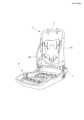
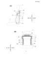
図1は、本発明に係るサイドエアバッグ装置を適用可能な車両用シートの主に外観形状を示す斜視図であり、サイドエアバッグ装置の図示は省略する。図2は、図1に示す車両用シートの骨組みとして機能する内部構造体(シートフレーム)を示す斜視図であり、ここでも、サイドエアバッグ装置の図示は省略する。 FIG. 1 is a perspective view mainly showing an external shape of a vehicle seat to which a side airbag device according to the present invention can be applied, and illustration of the side airbag device is omitted. FIG. 2 is a perspective view showing an internal structure (seat frame) that functions as a frame of the vehicle seat shown in FIG. 1, and the illustration of the side airbag device is also omitted here.
図1に示すように、車両用シートを部位として観たときには、乗員が着座する部分のシートクッション2と;背もたれを形成するシートバック1と;シートバック1の上端に連結されるヘッドレスト3とを含んでいる。 As shown in FIG. 1, when a vehicle seat is viewed as a part, a
図2に示すように、シートバック1の内部にはシートの骨格を形成するシートバックフレーム1fが設けられ、その表面及び周囲にはウレタン発泡材等からなるパッド、表皮(図示せず)が設けられている。シートクッション2についても、シートバック1と同様に、着座フレーム2fの上面及び周囲にはウレタン発泡材等からなるパッド、表皮(図示せず)が設けられている。なお、着座フレーム2fとシートバックフレーム1fとは、リクライニング機構4を介して連結されている。 As shown in FIG. 2, a seatback frame 1f that forms the skeleton of the seat is provided inside the
シートバックフレーム1fは、図2に示すように、左右に離間して配置され上下方向に延在するサイドフレーム10L,10Rと、これらのサイドフレーム10L,10Rの上端部を連結する上部フレーム11と、下端部を連結する下部フレームとにより枠状に構成されている。 As shown in FIG. 2, the seatback frame 1f includes side frames 10L and 10R that are spaced apart from each other in the left and right direction and extend in the vertical direction, and an
(第1実施例)
図3は、本発明の第1実施例に係るエアバッグ装置を車両用シートに搭載した様子を示す側面図(A)、正面図(B)であり、車両用シートに関しては透視で示すものとする。図4は、第1実施例に係るエアバッグ装置に採用されるエアバッグ14の構造を示すものであり、(A)がエアバッグ14を展開した状態(収容前の平置き状態)を示す平面図であり、(B)がロールした状態(収容時の状態)を示す正面図である。(First embodiment)
3A and 3B are a side view (A) and a front view (B) showing how the airbag device according to the first embodiment of the present invention is mounted on a vehicle seat. do. FIG. 4 shows the structure of the
本実施例に係るエアバッグ装置は、シートバック1の左右側部に収容され、膨張ガスを発生する一対のインフレータ12L,12Rと、ロールされ、又は折り畳まれた状態でシートバッグ1内に収容され、インフレータ12L,12Rから放出される膨張ガスによって展開するエアバッグ14とを備えている。なお、本実施例においては、シートバック1はヘッドレスト3と分離しているが、本発明に係るサイドエアバッグ装置は、ヘッドレスト一体型のシートバックにも適用することができる。 The airbag device according to the present embodiment includes a pair of
収容状態のエアバッグ14は、左右のサイドフレーム10L,10Rに沿って配置され、インフレータ12L,12Rよりも下側に位置する下部領域16L,16Rと、左右のサイドフレーム10L,10Rに加えて上部のシートフレーム11に沿って配置され、インフレータ12L,12Rよりも上側に位置する上部領域18とを備えている。 The
なお、図3において、エアバッグ14の上部領域18と下部領域16L,16Rとの境界位置をL0で示している。また、図4において、下部領域16L,16Rに対応する範囲、上部領域18に対応する範囲を一点鎖線で囲って示している。また、符号20L,20Rはインフレータ12L,12Rの導入部を示すものである。 In FIG. 3, the boundary position between the
上部領域18は、左右両側の下部領域16L,16Rの上端部分を連結するように形成され、シートバック1の上縁付近から、乗員の頭部を包むように展開するようになっている。これにより、下部領域16L,16Rが、主に乗員の腰部から胸部付近を保護し、上部領域18が、主に乗員の頭部付近(肩部から頭部)を保護するようになっている。 The
図3(B)に示すように、インフレータ12L,12Rは、サイドフレーム10L,10Rの内側にスタッドボルト(図示せず)等によって固定される。また、下部領域16L,16Rについても、サイドフレーム10L,10Rの内側に配置される。一方、上部領域18は、サイドフレーム10L,10Rの外側を通って、シートフレーム11の上部に配置される。シートフレーム11上の上部領域18aは、例えば、オメガ(Ω)状に折り畳まれた状態で収容される。 As shown in FIG. 3B, the
なお、本発明においては、単一のエアバッグ14を、インフレータ12L,12Rを境に、上部領域18と下部領域16L,16Rとに分割して説明しているが、少なくともインフレータ12L,12Rよりも上側を上部領域18とし、下側を下部領域16L,16Rと大まかに定義することもできる。 In the present invention, the
エアバッグ14をサイドフレーム10L,10Rに対して固定する際には、図4(B)に示すように、エアバッグ14を細長く圧縮した状態で、インフレータ12L,12Rを、スタッドボルト(図示せず)によってサイドフレーム10L,10Rの内側に固定する。このとき、下部領域16L,16Rも、サイドフレーム10L,10Rの内側に配置し、必要に応じてタブ等の連結具によってサイドフレーム10L,10Rに固定する。つづいて、インフレータ12L,12Rより上の部分(上部領域18)を屈曲させて、サイドフレーム10L,10Rの外側に配置する。 When fixing the
図5は、本発明の第1実施例に係るエアバッグ装置の作動状態(エアバッグ14の展開状態)を示すものであり、(A)が車両幅方向の側面から見た様子を示し、(B)が正面から見た様子を示すものである。 FIG. 5 shows the operating state of the airbag device (deployed state of the airbag 14) according to the first embodiment of the present invention. B) shows a state seen from the front.
車両の側面衝突等が発生すると、インフレータ12L,12Rから膨張ガスが放出されて、エアバッグ14が膨張・展開する。エアバッグ14の膨張が始まると、ガスが下部領域16L,16Rと上部領域18に流れ込む。エアバッグ14の下部領域16L,16Rは、サイドフレーム10L,10Rの内側で展開し、乗員方向(内側)及び前方(進行方向)に向かって展開する。このとき、下部領域16L,16Rは、サイドフレーム10L,10Rの内面(乗員側の面)を反力面として乗員側に展開するため、速やかに乗員の腰部から胸部周辺を拘束することができる。 When a vehicle side collision or the like occurs, inflation gas is released from the
一方、エアバッグ14の上部領域18は、シートバック1の上端からヘッドレスト3を飛び越えて前方に展開し、乗員の後頭部の後ろから前方に向かって覆い被さるようになる。このため、上部領域18がエアバッグ14の展開時に乗員の頭部に直接衝撃を与えることを回避できるとともに、乗員の頭部周辺の広い範囲に保護領域を形成することが可能となる。 On the other hand, the
このように、エアバッグ14の上部領域18は、サイドフレーム10L,10Rの外側で展開するため、シートを正面から見たときに下部領域16L,16Rよりも幅方向に大きく広がり、乗員の肩部から頭部周辺を確実に拘束することができる。 As described above, the
また、エアバッグ14の上部領域18は、乗員の肩付近でシートベルトSBの下側に入り込ませることができるため、シートベルトSBの反力を利用して展開することが可能となり、乗員の頭部周辺での展開形状が安定する。 In addition, since the
(第2実施例)
図6は、本発明の第2実施例に係るエアバッグ装置を車両用シートに搭載した様子を示す側面図(A)、正面図(B)であり、車両用シートに関しては透視で示すものとする。なお、上述した第1実施例と共通又は対応する構成要素については同一の符号を付し、重複した説明は省略する。(Second embodiment)
6A and 6B are a side view (A) and a front view (B) showing how an airbag device according to a second embodiment of the present invention is mounted on a vehicle seat. do. In addition, the same code|symbol is attached|subjected about the component which is common or respond|corresponds with 1st Example mentioned above, and the overlapping description is abbreviate|omitted.
本実施例においては、インフレータ12L,12Rをサイドフレーム10L,10Rの外側に配置した構造となっている。その他の構成は、第1実施例と同様である。このように、インフレータ12L,12Rをサイドフレーム10L,10Rの外側に配置することにより、インフレータ12L,12Rの設置場所の確保が容易、すなわち、高い自由度でインフレータ12L,12Rをサイドフレーム10L,10Rに容易に固定することができる。 In this embodiment, the
(第3実施例)
図7は、本発明の第3実施例に係るエアバッグ装置に採用されるエアバッグ14の構造を示すものであり、(A)がエアバッグ14を展開した状態(収容前に平置きした状態)を示す平面図であり、(B)がロールした状態(収容時の状態)を示す正面図である。図8は、本発明の第3実施例に係るエアバッグ装置の作動状態(エアバッグ14の展開状態)を概略的に示すものであり、車両幅方向の左側面から見た様子である。図9(A)は、図8のA1-A1方向の概略断面図である。図9(B)、(C)は、シートフレームとタブとの連結構造のバリエーションを示す断面図である。(Third embodiment)
FIG. 7 shows the structure of the
なお、上述した第1実施例及び第2実施例と共通又は対応する構成要素については同一の符号を付し、重複した説明は省略する。また、図8、図9においては、シートの左側のみを示すが、右側も同様の構成となっている。 In addition, the same code|symbol is attached|subjected about the component which is common or respond|corresponds to 1st Example and 2nd Example mentioned above, and the overlapping description is abbreviate|omitted. 8 and 9 show only the left side of the seat, the right side has the same configuration.
本実施例においては、エアバッグ14の左右下端部に固定用のタブ102L,102Rが取り付けられている。これらタブ102L(102R)の一端はエアバッグ14の下部領域16L(16R)に連結され、他端がシートフレーム10L(10R)に対して固定される。 In this embodiment, fixing
このようなタブ102L(102R)を用いてエアバッグ14の下部領域16L(16R)をシートフレーム10L(10R)に対して固定することにより、エアバッグ14が展開した時に、下部領域16L(16R)が必要以上に前方に飛び出したり、バタついたりすることもなく、当該下部領域16L(16R)の展開姿勢、展開挙動が安定することになる。その結果、シートフレーム10L(10R)の内側において乗員の腰部付近を確実に拘束することが可能となる。 By using
図9(A)に示すように、タブ102Lの他端(後端)は、シートフレーム10Lの後端部内側において、固定具104によって固定される。または、図9(B)に示すように、タブ102Lの他端(後端)は、シートフレーム10Lの後端部外側(背面側)において、固定具104によって固定される。あるいは、図9(C)に示すように、タブ102Lの他端(後端)は、シートフレーム10Lの内側(乗員側)から後端部(背面部)の後方を通ってシートフレーム10Lの外側(左側面側)に達し、固定具104によって固定される。 As shown in FIG. 9A, the other end (rear end) of the
本発明について実施例を参照して説明したが、本発明は上記実施例に限定されるものではない。すなわち、本発明の技術的思想の範囲を逸脱することなく、適宜変更可能なものである。 Although the present invention has been described with reference to examples, the present invention is not limited to the above examples. That is, it can be changed as appropriate without departing from the scope of the technical idea of the present invention.
Claims (12)
Translated fromJapanese前記車両用シートは、シートバック内部の左右側部にシートフレームが配置される構造であり、
当該エアバッグ装置は、
前記車両用シートの前記シートフレームの側部に固定され、膨張ガスを発生するインフレータと、
細長く圧縮された状態で前記シートバッグ内に収容され、前記インフレータから放出される膨張ガスによって膨張・展開するエアバッグと、を備え、
収容状態の前記エアバッグは、前記シートフレームに沿って配置され、前記インフレータよりも下側の下部領域と、前記インフレータよりも上側の上部領域とを含み、
前記下部領域が前記シートフレームの内側に配置され、前記上部領域が前記シートフレームの外側に配置されることを特徴とするエアバッグ装置。An airbag device installed in a vehicle seat,
The vehicle seat has a structure in which seat frames are arranged on left and right sides inside the seat back,
The airbag device is
an inflator fixed to a side portion of the seat frame of the vehicle seat and generating inflation gas;
an airbag that is housed in the seat bag in an elongated and compressed state and that is inflated and deployed by inflation gas emitted from the inflator;
The airbag in the accommodated state is arranged along the seat frame and includes a lower region below the inflator and an upper region above the inflator,
An airbag device, wherein the lower area is arranged inside the seat frame, and the upper area is arranged outside the seat frame.
前記上部領域は、これら左右両側の下部領域の上端部分を連結するように配置されることを特徴とする請求項2に記載のエアバッグ装置。The lower regions are arranged on both left and right sides of the seat back,
3. The airbag device according to claim 2, wherein the upper region is arranged to connect the upper end portions of the lower regions on both left and right sides.
前記タブの他端が前記シートフレームに対して固定されることを特徴とする請求項1乃至7の何れか1項に記載のエアバッグ装置。the airbag includes a locking tab having one end connected to the lower region;
8. The airbag device according to claim 1, wherein the other end of said tab is fixed to said seat frame.
Applications Claiming Priority (5)
| Application Number | Priority Date | Filing Date | Title |
|---|---|---|---|
| JP2020023895 | 2020-02-16 | ||
| JP2020023895 | 2020-02-16 | ||
| JP2020112188 | 2020-06-29 | ||
| JP2020112188 | 2020-06-29 | ||
| PCT/JP2021/001834WO2021161748A1 (en) | 2020-02-16 | 2021-01-20 | Airbag device and vehicle seat |
Publications (2)
| Publication Number | Publication Date |
|---|---|
| JPWO2021161748A1 JPWO2021161748A1 (en) | 2021-08-19 |
| JP7270826B2true JP7270826B2 (en) | 2023-05-10 |
Family
ID=77293144
Family Applications (1)
| Application Number | Title | Priority Date | Filing Date |
|---|---|---|---|
| JP2022500296AActiveJP7270826B2 (en) | 2020-02-16 | 2021-01-20 | Airbag device and vehicle seat |
Country Status (6)
| Country | Link |
|---|---|
| US (1) | US11858448B2 (en) |
| EP (1) | EP4105084B1 (en) |
| JP (1) | JP7270826B2 (en) |
| KR (1) | KR102729838B1 (en) |
| CN (1) | CN115003560B (en) |
| WO (1) | WO2021161748A1 (en) |
Families Citing this family (2)
| Publication number | Priority date | Publication date | Assignee | Title |
|---|---|---|---|---|
| KR102403511B1 (en)* | 2019-08-09 | 2022-05-31 | 아우토리브 디벨롭먼트 아베 | Airbag apparatus |
| JP7446790B2 (en)* | 2019-11-22 | 2024-03-11 | 株式会社ダイセル | Airbag devices and vehicle seats |
Citations (4)
| Publication number | Priority date | Publication date | Assignee | Title |
|---|---|---|---|---|
| US20070228699A1 (en) | 2006-03-31 | 2007-10-04 | Ford Global Technologies, Llc | Contoured side impact airbag |
| WO2018105324A1 (en) | 2016-12-05 | 2018-06-14 | オートリブ ディベロップメント エービー | Side air bag device |
| US20180194317A1 (en) | 2017-01-12 | 2018-07-12 | Ford Global Technologies, Llc | Seat supported airbag |
| JP2020501971A (en) | 2016-12-22 | 2020-01-23 | オートリブ ディベロップメント エービー | Airbag device and vehicle seat including airbag device |
Family Cites Families (23)
| Publication number | Priority date | Publication date | Assignee | Title |
|---|---|---|---|---|
| GB2397047B (en)* | 2003-01-10 | 2006-02-22 | Autoliv Development Ab | Improvements in or relating to vehicle air-seats and air-bag units |
| US7669888B2 (en)* | 2007-07-19 | 2010-03-02 | Toyoda Gosei Co., Ltd. | Side airbag apparatus |
| JP5467820B2 (en) | 2009-08-31 | 2014-04-09 | オートリブ ディベロップメント エービー | Side airbag device |
| EP2567870B1 (en)* | 2011-09-09 | 2015-03-25 | Autoliv Development AB | Vehicle seat with an airbag unit |
| JP5594327B2 (en)* | 2012-07-10 | 2014-09-24 | トヨタ自動車株式会社 | Vehicle seat |
| JP6269619B2 (en)* | 2015-08-25 | 2018-01-31 | トヨタ自動車株式会社 | Vehicle seat belt device and occupant protection device |
| JP6323438B2 (en)* | 2015-12-16 | 2018-05-16 | トヨタ自動車株式会社 | Vehicle seat with side airbag device |
| US9932011B2 (en)* | 2015-12-28 | 2018-04-03 | Toyoda Gosei Co., Ltd. | Side airbag apparatus |
| JP6428666B2 (en)* | 2016-02-10 | 2018-11-28 | トヨタ自動車株式会社 | Vehicle seat with side airbag device |
| JP6614047B2 (en)* | 2016-06-24 | 2019-12-04 | 豊田合成株式会社 | Side airbag device |
| JP6561942B2 (en)* | 2016-08-22 | 2019-08-21 | トヨタ自動車株式会社 | Vehicle seat with side airbag device |
| CN110431052B (en)* | 2017-03-30 | 2022-01-28 | 奥托立夫开发公司 | Occupant protection device |
| JP6783715B2 (en)* | 2017-07-11 | 2020-11-11 | 本田技研工業株式会社 | Airbag device |
| JP6919383B2 (en)* | 2017-07-18 | 2021-08-18 | トヨタ自動車株式会社 | Vehicle seats equipped with side airbag devices |
| US11351947B2 (en)* | 2018-01-11 | 2022-06-07 | Autoliv Development Ab | Passenger protection apparatus |
| KR102064844B1 (en)* | 2018-06-07 | 2020-01-10 | 아우토리브 디벨롭먼트 아베 | Airbag apparatus of vehicle |
| EP3581441B1 (en)* | 2018-06-13 | 2021-05-12 | Autoliv Development AB | A vehicle seat |
| JP7047701B2 (en)* | 2018-10-22 | 2022-04-05 | 豊田合成株式会社 | Side airbag device |
| EP3922517A4 (en)* | 2019-02-09 | 2022-12-14 | Autoliv Development AB | SIDE AIRBAG DEVICE |
| EP3978322A4 (en)* | 2019-05-31 | 2023-07-05 | Autoliv Development AB | Side airbag device and method for manufacturing side airbag device |
| EP4011710B1 (en)* | 2019-08-09 | 2025-03-26 | Autoliv Development AB | Airbag device |
| US12337784B2 (en)* | 2019-09-23 | 2025-06-24 | Autoliv Development Ab | Airbag device and vehicle seat |
| JP7449964B2 (en)* | 2020-01-23 | 2024-03-14 | オートリブ ディベロップメント エービー | air bag device |
- 2021
- 2021-01-20USUS17/904,169patent/US11858448B2/enactiveActive
- 2021-01-20EPEP21753543.4Apatent/EP4105084B1/enactiveActive
- 2021-01-20KRKR1020227031153Apatent/KR102729838B1/enactiveActive
- 2021-01-20WOPCT/JP2021/001834patent/WO2021161748A1/ennot_activeCeased
- 2021-01-20JPJP2022500296Apatent/JP7270826B2/enactiveActive
- 2021-01-20CNCN202180010085.XApatent/CN115003560B/enactiveActive
Patent Citations (4)
| Publication number | Priority date | Publication date | Assignee | Title |
|---|---|---|---|---|
| US20070228699A1 (en) | 2006-03-31 | 2007-10-04 | Ford Global Technologies, Llc | Contoured side impact airbag |
| WO2018105324A1 (en) | 2016-12-05 | 2018-06-14 | オートリブ ディベロップメント エービー | Side air bag device |
| JP2020501971A (en) | 2016-12-22 | 2020-01-23 | オートリブ ディベロップメント エービー | Airbag device and vehicle seat including airbag device |
| US20180194317A1 (en) | 2017-01-12 | 2018-07-12 | Ford Global Technologies, Llc | Seat supported airbag |
Also Published As
| Publication number | Publication date |
|---|---|
| CN115003560A (en) | 2022-09-02 |
| EP4105084A4 (en) | 2024-03-27 |
| EP4105084B1 (en) | 2025-09-10 |
| WO2021161748A1 (en) | 2021-08-19 |
| CN115003560B (en) | 2023-04-28 |
| US11858448B2 (en) | 2024-01-02 |
| US20230069779A1 (en) | 2023-03-02 |
| JPWO2021161748A1 (en) | 2021-08-19 |
| KR102729838B1 (en) | 2024-11-14 |
| EP4105084A1 (en) | 2022-12-21 |
| KR20220131391A (en) | 2022-09-27 |
Similar Documents
| Publication | Publication Date | Title |
|---|---|---|
| JP6756922B2 (en) | Vehicle seat with airbag device and airbag device | |
| KR102064844B1 (en) | Airbag apparatus of vehicle | |
| KR102839909B1 (en) | airbag device | |
| JP7222110B2 (en) | Airbag device and vehicle seat | |
| JP6748294B2 (en) | Occupant protection device | |
| KR102656870B1 (en) | Side airbag device, vehicle seat equipped therewith, and method of manufacturing the side airbag device | |
| JP6940627B2 (en) | Crew protection device | |
| JP7402783B2 (en) | Vehicle seat/airbag integrated occupant protection device | |
| US11358555B2 (en) | Vehicle seat | |
| JP6755072B2 (en) | Vehicle structure | |
| CN116194344A (en) | Airbag device | |
| JP7270826B2 (en) | Airbag device and vehicle seat | |
| WO2019146382A1 (en) | Side air bag device and vehicle seat with same | |
| CN117284234B (en) | Airbag device, vehicle seat, and vehicle | |
| JP2019131160A (en) | Side air bag device and vehicular seat comprising the same | |
| CN117841894B (en) | Airbag device, vehicle seat, and vehicle | |
| JP7381772B2 (en) | Seat built-in airbag device | |
| KR102408036B1 (en) | Airbag apparatus | |
| WO2021166530A1 (en) | Side airbag device | |
| JP7514307B2 (en) | Airbag device | |
| JP7519393B2 (en) | Seat-mounted airbag device | |
| WO2022209259A1 (en) | Side airbag device and method for manufacturing same | |
| WO2024128054A1 (en) | Side airbag device | |
| JP2023046992A (en) | Airbag device and passenger vehicle provided with airbag device |
Legal Events
| Date | Code | Title | Description |
|---|---|---|---|
| A621 | Written request for application examination | Free format text:JAPANESE INTERMEDIATE CODE: A621 Effective date:20220526 | |
| TRDD | Decision of grant or rejection written | ||
| A01 | Written decision to grant a patent or to grant a registration (utility model) | Free format text:JAPANESE INTERMEDIATE CODE: A01 Effective date:20230404 | |
| A61 | First payment of annual fees (during grant procedure) | Free format text:JAPANESE INTERMEDIATE CODE: A61 Effective date:20230425 | |
| R150 | Certificate of patent or registration of utility model | Ref document number:7270826 Country of ref document:JP Free format text:JAPANESE INTERMEDIATE CODE: R150 | |
| RD03 | Notification of appointment of power of attorney | Free format text:JAPANESE INTERMEDIATE CODE: R3D03 |