JP7268190B2 - Medical devices for tissue hemostasis or tissue closure - Google Patents
Medical devices for tissue hemostasis or tissue closureDownload PDFInfo
- Publication number
- JP7268190B2 JP7268190B2JP2021558877AJP2021558877AJP7268190B2JP 7268190 B2JP7268190 B2JP 7268190B2JP 2021558877 AJP2021558877 AJP 2021558877AJP 2021558877 AJP2021558877 AJP 2021558877AJP 7268190 B2JP7268190 B2JP 7268190B2
- Authority
- JP
- Japan
- Prior art keywords
- clamping
- sheath
- clamp
- connecting element
- arms
- Prior art date
- Legal status (The legal status is an assumption and is not a legal conclusion. Google has not performed a legal analysis and makes no representation as to the accuracy of the status listed.)
- Active
Links
Images


Classifications
- A—HUMAN NECESSITIES
- A61—MEDICAL OR VETERINARY SCIENCE; HYGIENE
- A61B—DIAGNOSIS; SURGERY; IDENTIFICATION
- A61B17/00—Surgical instruments, devices or methods
- A61B17/12—Surgical instruments, devices or methods for ligaturing or otherwise compressing tubular parts of the body, e.g. blood vessels or umbilical cord
- A61B17/128—Surgical instruments, devices or methods for ligaturing or otherwise compressing tubular parts of the body, e.g. blood vessels or umbilical cord for applying or removing clamps or clips
- A61B17/1285—Surgical instruments, devices or methods for ligaturing or otherwise compressing tubular parts of the body, e.g. blood vessels or umbilical cord for applying or removing clamps or clips for minimally invasive surgery
- A—HUMAN NECESSITIES
- A61—MEDICAL OR VETERINARY SCIENCE; HYGIENE
- A61B—DIAGNOSIS; SURGERY; IDENTIFICATION
- A61B17/00—Surgical instruments, devices or methods
- A61B17/12—Surgical instruments, devices or methods for ligaturing or otherwise compressing tubular parts of the body, e.g. blood vessels or umbilical cord
- A61B17/122—Clamps or clips, e.g. for the umbilical cord
- A61B17/1227—Spring clips
- A—HUMAN NECESSITIES
- A61—MEDICAL OR VETERINARY SCIENCE; HYGIENE
- A61B—DIAGNOSIS; SURGERY; IDENTIFICATION
- A61B17/00—Surgical instruments, devices or methods
- A61B2017/00477—Coupling
- A—HUMAN NECESSITIES
- A61—MEDICAL OR VETERINARY SCIENCE; HYGIENE
- A61B—DIAGNOSIS; SURGERY; IDENTIFICATION
- A61B17/00—Surgical instruments, devices or methods
- A61B2017/00831—Material properties
- A61B2017/00862—Material properties elastic or resilient
- A—HUMAN NECESSITIES
- A61—MEDICAL OR VETERINARY SCIENCE; HYGIENE
- A61B—DIAGNOSIS; SURGERY; IDENTIFICATION
- A61B17/00—Surgical instruments, devices or methods
- A61B17/12—Surgical instruments, devices or methods for ligaturing or otherwise compressing tubular parts of the body, e.g. blood vessels or umbilical cord
- A61B2017/12004—Surgical instruments, devices or methods for ligaturing or otherwise compressing tubular parts of the body, e.g. blood vessels or umbilical cord for haemostasis, for prevention of bleeding
- A—HUMAN NECESSITIES
- A61—MEDICAL OR VETERINARY SCIENCE; HYGIENE
- A61B—DIAGNOSIS; SURGERY; IDENTIFICATION
- A61B17/00—Surgical instruments, devices or methods
- A61B17/12—Surgical instruments, devices or methods for ligaturing or otherwise compressing tubular parts of the body, e.g. blood vessels or umbilical cord
- A61B17/12022—Occluding by internal devices, e.g. balloons or releasable wires
- A61B2017/1205—Introduction devices
- A61B2017/12054—Details concerning the detachment of the occluding device from the introduction device
Landscapes
- Health & Medical Sciences (AREA)
- Surgery (AREA)
- Life Sciences & Earth Sciences (AREA)
- Heart & Thoracic Surgery (AREA)
- Nuclear Medicine, Radiotherapy & Molecular Imaging (AREA)
- Vascular Medicine (AREA)
- Engineering & Computer Science (AREA)
- Biomedical Technology (AREA)
- Reproductive Health (AREA)
- Medical Informatics (AREA)
- Molecular Biology (AREA)
- Animal Behavior & Ethology (AREA)
- General Health & Medical Sciences (AREA)
- Public Health (AREA)
- Veterinary Medicine (AREA)
- Surgical Instruments (AREA)
Description
Translated fromJapanese本出願は、医療器具の分野に属し、具体的に、組織止血又は組織閉鎖用の医療器具に関する。 The present application is in the field of medical devices and specifically relates to medical devices for tissue hemostasis or tissue closure.
関係出願の相互参照
本出願は、2019年7月10日に欧州特許庁に提出された、出願番号がEP19185556.8であり、名称が「血管止血用医療器具」である欧州出願に基づいて優先権を主張し、その全ての内容が、参照により本出願に組み込まれる。CROSS-REFERENCE TO RELATED APPLICATIONS This application takes precedence over European application number EP19185556.8 and titled "Medical Devices for Vaseostatics" filed with the European Patent Office on July 10, 2019. , the entire contents of which are hereby incorporated by reference into this application.
従来技術において、例えば、EP 1 328 199 B1に、特に消化管の出血の治療に使用される医療器具が開示された。具体的に、このような装置は、血管に必要な収縮力を与えることにより該血管における血液の流動を制限し又は遮断するように、出血している血管を挟むためのクランプ又はクリップをセットすることに用いられる。 In the prior art, for example EP 1 328 199 B1 disclosed a medical device used in particular for the treatment of gastrointestinal bleeding. Specifically, such devices set clamps or clips to pinch a bleeding vessel so as to restrict or block blood flow in the vessel by imparting the necessary contractile force to the vessel. used for
EP 1 328 199 B1による医療器具は、ハンドルと、ハンドルに取り付けられるシースとを備える。コントロールワイヤは、シースを穿通して延在し、アクチュエータによって駆動でき、該アクチュエータがコントロールワイヤの近位端に連結され、コントロールワイヤを、遠位側方向及び近位側方向に可逆的に移動させる。医療器具は、シースの遠位端に設置されるスリーブと、J形フックによってコントロールワイヤの遠位端に連結された2つのクランプアームを備えるクリップとを含むクランプ装置とをさらに備える。近位側方向へコントロールワイヤを引っ張るとき、クランプアームがスリーブの前縁と接触して内側へ弾性変形しながら閉じられ、遠位側方向へコントロールワイヤを押すとき、クランプアームがスリーブから遠位側へ押し出され、クランプアームが弾性復元力よって自動的に再開放するように、クランプアームはスリーブと協働する。クランプ装置は、繰り返して開閉できるため、クランプ装置の設置が容易である。 A medical instrument according to EP 1 328 199 B1 comprises a handle and a sheath attached to the handle. A control wire extends through the sheath and can be driven by an actuator coupled to a proximal end of the control wire to reversibly move the control wire in distal and proximal directions. . The medical device further comprises a clamping device including a sleeve positioned at the distal end of the sheath and a clip comprising two clamping arms connected to the distal end of the control wire by a J-hook. When the control wire is pulled proximally, the clamp arm comes into contact with the front edge of the sleeve and is closed while being elastically deformed inward, and when the control wire is pushed distally, the clamp arm moves distally from the sleeve. The clamp arm cooperates with the sleeve such that the clamp arm automatically reopens due to the elastic restoring force. Since the clamping device can be opened and closed repeatedly, installation of the clamping device is easy.
クランプ装置を正確に位置にセットできたら、クランプアームとスリーブとを含むクランプ装置を医療器具の他の部分から分離させればよい。そうするために、クランプ装置が完全に閉じたとき、コントロールワイヤをさらに引き戻せば、J形フックが破断し、クランプアームとコントロールワイヤとの連結が解除される。そして、コントロールワイヤをさらに引き戻せば、コントロールワイヤとスリーブとを接続する保持部材が駆動され、保持部材とスリーブとが分離されて、コントロールワイヤとスリーブとの接続が解除される。 Once the clamping device is properly positioned, the clamping device, including the clamp arm and sleeve, can be separated from the rest of the medical device. To do so, when the clamping device is fully closed, the control wire is further pulled back, breaking the J-shaped hook and disconnecting the clamping arm from the control wire. When the control wire is further pulled back, the holding member connecting the control wire and the sleeve is driven, the holding member and the sleeve are separated, and the connection between the control wire and the sleeve is released.
従来技術における少なくとも1つの問題を解決するため、本発明は、操作、製造及び組立に容易である医療器具を提供することを目的とする。 SUMMARY OF THE INVENTION To overcome at least one problem in the prior art, the present invention aims to provide a medical device that is easy to operate, manufacture and assemble.
本発明の実施例による組織止血又は組織閉鎖用の医療器具は、ハンドルと、ハンドルに取り付けられるシース装置と、クランプベースを有するクランプハウジングと、少なくとも2つのクランプアームを備え、特に、該クランプベースが、シース装置の遠位端にセットされるスリーブの形態のものであるクランプ装置と、シース装置を穿通して延在し、遠位側方向及び近位側方向に可逆的に移動可能であるコントロールワイヤと、コントロールワイヤの近位端に連結され、コントロールワイヤを遠位端方向及び近位端方向に可逆的に移動させるように駆動されることができるアクチュエータと、を備え、クランプアームのそれぞれがコントロールワイヤの遠位端に連結され、コントロールワイヤの近位側方向への移動がクランプアームの閉じる移動に変換され、コントロールワイヤの遠位側方向への移動がクランプアームの開放移動に変換されるように、コントロールワイヤの移動により、クランプ装置のクランプアームが開閉駆動される。 A medical device for tissue hemostasis or tissue closure according to an embodiment of the present invention comprises a handle, a sheath device attached to the handle, a clamp housing having a clamp base, and at least two clamp arms, in particular the clamp base having a clamping device in the form of a sleeve that is set at the distal end of the sheath device; and a control that extends through the sheath device and is reversibly movable in distal and proximal directions. a wire and an actuator coupled to a proximal end of the control wire and operable to reversibly move the control wire distally and proximally; Coupled to the distal end of the control wire such that proximal movement of the control wire translates to closing movement of the clamp arm and distal movement of the control wire translates to opening movement of the clamp arm. Thus, movement of the control wire drives the clamp arm of the clamp device to open and close.
任意選択で、クランプハウジングが少なくとも1つの接続素子により直接シース装置に接続され、各接続素子がクランプハウジングに固定的に取り付けられ又はクランプハウジングの一部として形成されるとともに、シース装置に外し可能に接続され、各接続素子と協働する釈放機構が設置され、クランプアームが閉じたとき、コントロールワイヤの近位端方向への移動により該釈放機構が駆動されることにより、シース装置から各接続素子がリリースされてクランプハウジングが釈放される。 Optionally, the clamp housing is directly connected to the sheath device by at least one connecting element, each connecting element being fixedly attached to or formed as part of the clamp housing and removably attached to the sheath device. A release mechanism is provided that is connected and associated with each connecting element such that movement of the control wire toward the proximal end actuates the release mechanism to release each connecting element from the sheath device when the clamp arms are closed. is released to release the clamp housing.
任意選択で、クランプハウジングとシース装置とは相応の接続素子により互いに直接接続され、前記接続素子がクランプハウジングに固定的に設置され又はクランプハウジングの一部として形成されるとともに、シース装置に外し可能に接続される。このようにして、クランプハウジングとシース装置とは、とても確実且つ安定に接続することができる。また、本出願に係る医療器具は、設計構成が簡単で、製造が容易である。 Optionally, the clamping housing and the sheathing device are directly connected to each other by corresponding connecting elements, said connecting elements being fixedly mounted on the clamping housing or formed as part of the clamping housing and detachable from the sheathing device. connected to In this way, a very secure and stable connection can be achieved between the clamp housing and the sheath device. In addition, the medical device according to the present application has a simple design configuration and is easy to manufacture.
クランプアームが閉じたとき、接続素子を駆動して、クランプベースをシース装置から釈放することができる。具体的に、クランプアームが閉じたときにコントロールワイヤを近位端方向へさらに移動させれば、クランプハウジングがシース装置から釈放されるように構成される。 When the clamping arms are closed, the connecting element can be actuated to release the clamping base from the sheath device. Specifically, further movement of the control wire proximally when the clamp arm is closed is configured to release the clamp housing from the sheath device.
本出願の選択可能な実施形態によれば、シース装置はシースを備え、任意選択で、伸長可能な螺旋シース(coiled sheath)を備え、シースの遠位端に設置される接続管をさらに備える。任意選択で、接続管がシースに接続される方式により、接続管がその縦方向の中心軸線回りにシースに対して回動することができる。このために、接続管をシースに接続/連結するように、接続管の外周面に環状溝が設けられ、係合部材がシースに固定的に設置され、任意選択で、シースに溶接され、係合部材が環状溝に係合される。このような接続関係で、係合部材が環状溝における環状の肩部と係合可能である。 According to optional embodiments of the present application, the sheath device comprises a sheath, optionally comprising an extendable coiled sheath and further comprising a connecting tube located at the distal end of the sheath. Optionally, the manner in which the connecting tube is connected to the sheath allows the connecting tube to pivot relative to the sheath about its longitudinal central axis. For this purpose, an annular groove is provided on the outer peripheral surface of the connecting tube so as to connect/couple the connecting tube to the sheath, and an engaging member is fixedly mounted on the sheath, optionally welded to the sheath and engaged. A mating member is engaged in the annular groove. In such connected relationship, the engagement member is engageable with an annular shoulder in the annular groove.
任意選択で、少なくとも2つの接続素子が設置され、接続素子がクランプハウジングの外周に沿って規定の角度でずれて位置設定される。任意選択で、2つの接続素子が設置され、この2つの接続素子がそれぞれクランプハウジングの対向する両側に設置される。 Optionally, at least two connecting elements are provided, the connecting elements being positioned offset at a defined angle along the circumference of the clamp housing. Optionally, two connection elements are provided, each on opposite sides of the clamp housing.
本出願の選択可能な実施形態として、接続素子は、弾性を有して弾性変形可能な接続アームで構成され、接続素子の遠位端がクランプハウジングに固定的に取り付けられ、接続素子の自由近位端が、クランプハウジングをシース装置に接続するようにシース装置における相応の係合手段と係合する係合部として形成され、釈放機構は突起部を有し、該突起部が接続素子の間に配置されるとともに接続素子と協働し、突起部が接続素子を押圧し、接続素子が外側へ弾性変形して、接続素子の係合部が外側へ押されてシース装置の相応の係合手段と係合することにより、クランプハウジングがシース装置に接続され、そして、突起部がコントロールワイヤに連結され、特に、コントロールワイヤに固定的に設置されることにより、クランプアームが閉じた後、コントロールワイヤが近位端方向へさらに移動すると、突起部がコントロールワイヤと共に接続素子との係合から外され、接続素子がその弾性復元力によって内側へ変形して接続素子の係合部がシース装置の相応の係合手段との係合から外されて、シース装置からクランプハウジングが釈放される。 In an optional embodiment of the present application, the connecting element consists of an elastic, elastically deformable connecting arm, the distal end of the connecting element being fixedly attached to the clamp housing and the free proximal end of the connecting element. The proximal end is formed as an engaging portion that engages with corresponding engaging means on the sheath device to connect the clamp housing to the sheath device, the release mechanism having a projection which extends between the connecting elements. and cooperating with the connecting element, the projection presses the connecting element, the connecting element is elastically deformed outward, and the engaging portion of the connecting element is pushed outward to correspondingly engage the sheath device. The clamp housing is connected to the sheath device by engaging the means, and the projection is coupled to the control wire, in particular fixedly mounted on the control wire, so that after the clamp arm is closed, the control Further movement of the wire in the proximal direction disengages the protrusion from the connecting element together with the control wire, and the elastic restoring force of the connecting element deforms inwardly so that the engaging portion of the connecting element is pulled out of the sheath device. The clamp housing is released from the sheath device by being disengaged from the corresponding engagement means.
任意選択で、接続素子に凸起セクションが設けられ、特に、該凸起セクションが接続素子の自由端の箇所に設けられ、突起部が、接続素子の凸起セクションの間に配置され、接続素子を外側へ変形させるように凸起セクションと協働し、突起部が凸起セクションとの係合から外されると、接続素子がその弾性復元力によって内側へ変形する。 Optionally, the connecting element is provided with a raised section, in particular the raised section is provided at the location of the free end of the connecting element, the protrusion is arranged between the raised sections of the connecting element, , so that when the protrusion is disengaged from the raised section, the connecting element deforms inward due to its elastic restoring force.
任意選択で、弾性接続素子の係合部は、突起部と接続素子(特に、接続素子の凸起セクション)との係合によりクランプベースに設置される係合手段と主動的に係合する。この係合が解除された場合、コントロールワイヤが近位端方向へ引き戻されて、突起部が接続素子/凸起セクションの間に配置/位置しなくなるため、接続素子がその復元力によって内側へ弾性変形する。つまり、コントロールワイヤの突起部が接続素子又は凸起セクションの範囲外に移動することにより、シース装置とクランプベースとの接続が受動的に解除される。 Optionally, the engaging portion of the resilient connecting element actively engages with engaging means provided on the clamp base by engagement of the projection with the connecting element (particularly the raised section of the connecting element). When this engagement is disengaged, the control wire is pulled back in the proximal direction such that the protrusion is no longer positioned/positioned between the connecting element/raised section so that the connecting element is elastically inwardly exerted by its restoring force. transform. That is, the connection between the sheath device and the clamp base is passively released by moving the projection of the control wire out of the connection element or raised section.
本出願の選択可能な形態として、押入(嵌入)接続によりクランプハウジングがシース装置に接続されて、重なり合った部分が形成され、任意選択で、クランプハウジングの近位端がシース装置の遠位端に挿入され、係合手段がシース装置の内周壁における凹部又は貫通孔で構成され、好ましくは、接続素子の係合部が外向きの指状係合部と形成される。 As an optional form of the present application, a push-fit connection connects the clamp housing to the sheath device to form an overlapping portion, optionally connecting the proximal end of the clamp housing to the distal end of the sheath device. When inserted, the engagement means are constituted by recesses or through-holes in the inner peripheral wall of the sheath device, preferably the engagement portion of the connecting element is formed with an outwardly directed finger-like engagement portion.
任意選択で、クランプハウジングをシース装置に接続するように、シース装置の係合手段及び対応の孔は、シース装置とクランプハウジングとの重なり合った部分に設けられ、接続素子の係合部がクランプハウジングにおける孔に通されて外側へ押されてシース装置の係合手段に押される。 Optionally, the engaging means and corresponding apertures of the sheath device are provided in the overlapping portions of the sheath device and the clamp housing so as to connect the clamp housing to the sheath device, and the engagement portion of the connecting element is in the clamp housing. is passed through the hole in the sheath and pushed outward to the engaging means of the sheath device.
接続素子はストレートセクションを有し、近位端方向に向かって観察する場合、該ストレートセクションがクランプハウジングの縦方向の中心軸線に対して内側へ傾斜し、特に、傾斜角度が3°~15°であり、任意選択で、5°である。 The connecting element has a straight section which, when viewed toward the proximal end, is inclined inwardly with respect to the longitudinal central axis of the clamp housing, in particular at an angle of inclination of 3° to 15°. and optionally 5°.
本出願の選択可能な実施形態として、接続素子が遠位端セクションでクランプハウジングに固定的に接続され、特に、接続素子の遠位端が、径方向において外側に向かってクランプハウジングに設けられた相応の保持孔内まで延在し、任意選択で、溶接により保持孔に固定される。 As an alternative embodiment of the present application, the connecting element is fixedly connected to the clamping housing at the distal end section, in particular the distal end of the connecting element is provided radially outwards on the clamping housing. It extends into the corresponding retaining holes and is optionally fixed to the retaining holes by welding.
任意選択で、クランプハウジングは、クランプベースから遠位端方向へ延在する2つの軸受アームを有し、接続素子が軸受アームの自由端セクションで軸受アームに固定的に取り付けられ、特に、2つの軸受アームの間にガイドピンが保持され、接続素子がガイドピンの近位端側に設置される。Optionally, the clamp housing has two bearing arms extending distally from the clamp base, the connecting element being fixedly attached to the bearing arms at the free end sections of the bearing arms, in particular the two A guide pin is held between the bearing arms and a connecting element is locatedproximally of the guide pin.
本出願の選択可能な実施形態として、クランプアームは枢動ピンを介してコントロールワイヤに連結され、該枢動ピンがコントロールワイヤの遠位端セクションに設置されるとともに、クランプアームの尾端における相応の貫通孔を穿通して延在し、クランプアームの尾端において、貫通孔の近位端側に出口通路が設けられ、クランプアームが閉じた後、該枢動ピンが、該出口通路に通されて貫通孔及びクランプアームから引き出されることができ、コントロールワイヤとクランプアームとを分離させるためのコントロールワイヤの近位端への移動により尾端セクションが断裂することがないように、出口通路の対向する両側においてクランプアームの尾端セクションが離間する。 In an optional embodiment of the present application, the clamp arm is connected to the control wire via a pivot pin, the pivot pin being located on the distal end section of the control wire and a corresponding arm at the caudal end of the clamp arm. and an exit passage is provided at the proximal end of the through-hole at the caudal end of the clamp arm, the pivot pin passing through the exit passage after the clamp arm is closed. can be pulled out of the through hole and the clamp arm, and the proximal movement of the control wire to separate the control wire and clamp arm does not tear the caudal section. The caudal sections of the clamp arms are spaced apart on opposite sides.
任意選択で、クランプアームがコントロールワイヤに直接連結されるため、J形フックのような形態の別体の連結素子を設置する必要がない。具体的に、コントロールワイヤの遠位端セクションに枢動ピンが設置され、該枢動ピンがクランプアームの近位端セクションに設けられた相応の貫通孔と係合する。 Optionally, there is no need to install a separate coupling element in the form of a J-hook, as the clamp arm is directly coupled to the control wire. Specifically, a pivot pin is provided at the distal end section of the control wire and engages with a corresponding through hole provided at the proximal end section of the clamp arm.
貫通孔はクランプアームの近位端に向かって開放する。具体的に、出口通路は、枢動ピンのクランプアームからの意図しない脱出がないとともに、コントロールワイヤに十分な引張力を与えることにより出口通路の対向する両側のクランプアームの尾端セクションが離間して変形するように意図的に枢動ピンを出口通路に通して貫通孔から引き出すことができるように、十分小さく設計されている。 The through hole opens toward the proximal end of the clamp arm. Specifically, the exit passageway is such that there is no unintentional escape of the pivot pin from the clamp arm, and sufficient pulling force on the control wire separates the caudal sections of the clamp arms on opposite sides of the exit passageway. It is designed to be small enough so that the pivot pin can be intentionally pulled through the outlet passage and out of the through hole so as to be deformed by force.
出口通路は、例えば、クランプアームの尾端におけるスリットで形成される。 The exit passage is formed, for example, by a slit in the tail end of the clamp arm.
本出願の選択可能な実施形態によれば、クランプアームの尾端セクションが離間するとき、弾性変形又は塑性変形する。いずれの状況でも、尾端セクションが断裂することがなく、断裂したアームの一部が勝手に患者の体内に残されることを防ぐことができる。 According to optional embodiments of the present application, the caudal sections of the clamping arms elastically or plastically deform as they move apart. In either situation, the caudal section is not torn, preventing a torn portion of the arm from being left unintentionally in the patient's body.
本出願の選択可能な一実施形態では、クランプアームをクランプベースにロックするように、出口通路の対向する両側のクランプアームの尾端セクションが、クランプベースの少なくとも1つの肩部の後方に係合される。任意選択で、クランプアームをクランプベースにロックするように、出口通路の対向する両側のクランプアームの尾端セクションが、クランプベースの前記少なくとも1つの肩部の後方に係合するフックと形成される。 In one optional embodiment of the present application, tail sections of the clamp arms on opposite sides of the outlet passage engage behind at least one shoulder of the clamp base to lock the clamp arms to the clamp base. be done. Optionally, tail sections of the clamp arms on opposite sides of the outlet passage are formed with hooks engaging rearwardly of said at least one shoulder of the clamp base to lock the clamp arms to the clamp base. .
肩部は、クランプベースの環状突起部で形成され、特に、環状突起部が中央開口を有するクランプベースの遠位端面を形成し、クランプアームが完全に閉じたとき、クランプアームの尾端が該開口を通過してクランプベース内まで延伸することができる。 The shoulder is formed by an annular protrusion of the clamp base, in particular the annular protrusion forms a distal end face of the clamp base having a central opening, the tail end of the clamp arm resting against it when the clamp arm is fully closed. It can extend through the opening and into the clamp base.
クランプアームの出口通路の対向する両側の尾端セクションは、塑性変形する場合、枢動ピンをクランプアームとの係合から引き出すときにクランプアームの近位端を後方、即ちクランプベースの肩部の近位端側に位置させ、クランプアームを塑性変形させて肩部の後方に係合させてクランプアームをクランプベースにロックし、したがって、クランプアームがクランプベースから取り外されることができなくなる。このようにして、別体のロック素子が不要になる。 Opposite tail sections of the exit passage of the clamp arm, when plastically deformed, push the proximal end of the clamp arm rearward, i.e., behind the shoulder of the clamp base, when the pivot pin is pulled out of engagement with the clamp arm. Positioned proximally, the clamp arm is plastically deformed to engage behind the shoulder to lock the clamp arm to the clamp base so that the clamp arm cannot be removed from the clamp base. In this way, no separate locking element is required.
本出願の選択可能な実施形態では、コントロールワイヤの遠位端にカップリングヘッドが設置され、カップリングヘッドに枢動ピンが設置される。任意選択で、カップリングヘッドは、遠位端側で開放したU字状保持構造を有し、クランプアームの一部がU字状保持構造の脚部の間に配置され、枢動ピンが、U字状保持構造の脚部の間に保持されるとともに、クランプアームの貫通孔を穿通して延在する。特に、クランプアームがU字状保持構造の開放した側面から側方に外へ延出する。該実施形態において、クランプアームがU字状保持構造に配置されるため、互いに直接接触できる。 In an optional embodiment of the present application, a coupling head is mounted on the distal end of the control wire and a pivot pin is mounted on the coupling head. Optionally, the coupling head has a U-shaped retaining structure open at the distal end, a portion of the clamp arm being disposed between the legs of the U-shaped retaining structure, the pivot pin comprising: It is held between the legs of the U-shaped retaining structure and extends through a through hole in the clamp arm. Specifically, a clamp arm extends laterally out from the open side of the U-shaped retaining structure. In this embodiment, the clamping arms are arranged in a U-shaped holding structure so that they can directly contact each other.
本出願の選択可能な実施形態では、その目的が最初に言及した医療器具で達成される。その特徴として、クランプ装置は、2つのクランプアームと、ガイドピンとを備え、2つのクランプアームが、互いに別体の素子として構成され、各クランプアームが枢動ピンによって規定された共通の枢動軸線回りに枢動可能にコントロールワイヤの遠位端に連結され、クランプアームのそれぞれにガイド溝が設けられ、クランプアームのガイド溝が部分的に重なり合い、ガイドピンが、クランプハウジングに取り付けられるとともにガイド溝の重なり合った部分でガイド溝を穿通して延在し、ガイドピンとガイド溝との係合により、コントロールワイヤの近位側方向への移動がクランプアームの閉じる移動に変換され、コントロールワイヤの遠位側方向への移動がクランプアームの枢動軸線回りの開放移動に変換される。 In optional embodiments of the present application, that objective is achieved with the first-mentioned medical device. Characteristically, the clamping device comprises two clamping arms and a guide pin, the two clamping arms being constructed as separate elements from each other, each clamping arm having a common pivot axis defined by a pivot pin. A guide groove is provided in each of the clamp arms, the guide grooves of the clamp arms partially overlap, and a guide pin is attached to the clamp housing and in the guide groove. and the engagement of the guide pin with the guide groove translates proximal movement of the control wire into closing movement of the clamp arm and distal movement of the control wire. Lateral movement is translated into opening movement about the pivot axis of the clamp arm.
任意選択で、クランプアームは互いに直接接続しない素子/部品である。逆に、クランプアームは、それぞれ貫通孔と枢動ピンとの係合によりコントロールワイヤに連結される。そして、クランプアームは、ガイドピンとガイド溝との係合によりクランプハウジングに連結されて、コントロールワイヤの軸方向の移動がクランプアームの枢動軸線回りの閉じる移動/開放移動に変換される。選択可能な一実施形態では、ガイドピンは、クランプハウジングにおける、クランプベースから遠位端方向へ延在する2つの軸受アームの間に保持され、特に、軸受アームの自由端セクションに保持される。この場合、ガイドピンの近位端側に接続素子を設置することができる。 Optionally, the clamp arms are elements/parts that are not directly connected to each other. Conversely, the clamp arms are coupled to the control wires by engagement of respective through holes and pivot pins. The clamp arm is then coupled to the clamp housing by engagement of the guide pin and the guide groove so that axial movement of the control wire is converted into closing/opening movement of the clamp arm about the pivot axis. In one alternative embodiment, the guide pin is held in the clamp housing between two bearing arms extending distally from the clamp base, in particular in the free end sections of the bearing arms. In this case, the connecting element can be placed on the proximal end side of the guide pin.
任意選択で、クランプアームに保持凸部が設けられ、該保持凸部は、ガイド溝の側面からガイド溝内まで延在するとともに、ガイドピンが保持凸部を通過してガイド溝の遠位端に到達することを許容するが、ガイドピンの反対方向への通過を阻止するように構成された。特に、ガイド溝が軸方向に延在するストレートな遠位端セクションを有し、ガイドピンが、クランプアームの更なる回動にならないように該遠位端セクション内を移動可能であり、保持凸部がストレートな端部内まで延在する。特に、保持凸部の遠位端側において、ガイド溝の側面に凹部が形成され、ガイドピンが保持凸部を通過してガイド溝における遠位端位置に到達することを許容するように保持凸部が弾性変形して該凹部に入ることができる。 Optionally, the clamp arm is provided with a retaining projection extending from the side of the guide groove into the guide groove and the guide pin passing through the retaining projection to the distal end of the guide groove. , but prevented passage of the guide pin in the opposite direction. In particular, the guide groove has an axially extending straight distal end section, the guide pin being movable within said distal end section against further pivoting of the clamping arm and the retaining projection. extends into the straight end. In particular, on the distal end side of the holding protrusion, a recess is formed in the side surface of the guide groove, and the holding protrusion is formed so as to allow the guide pin to pass through the holding protrusion and reach the distal end position in the guide groove. The portion can be elastically deformed to enter the recess.
任意選択で、ガイドピンを保持凸部によってガイド溝の遠位端に拘束(制限)することにより、クリップをクランプベースにロックする。このようにして、別体のロック素子が不要になる。 Optionally, the clip is locked to the clamp base by constraining (limiting) the guide pin to the distal end of the guide channel by a retaining projection. In this way, no separate locking element is required.
以下、図面を参照しながら本開示の実施例を説明する。 Hereinafter, embodiments of the present disclosure will be described with reference to the drawings.
図1~13には、本出願に係る医療器具の実施形態が示されている。該医療器具は、内視鏡によりクリップを目標部位まで送り、消化管に沿って分布する血管の止血のためのクリップをセットすることに用いられる。 1-13 illustrate embodiments of medical devices according to the present application. The medical device is used to endoscopically deliver a clip to a target site and set the clip for hemostasis in blood vessels distributed along the gastrointestinal tract.
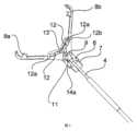
図1に示すように、医療器具は、ハンドル1と、ハンドル1に取り付けられるシース装置2と、シース装置2の遠位端にセットされるクランプ装置3とを備える。コントロールワイヤ4は、シース装置2を穿通して延在し、シース装置の近位端の箇所でアクチュエータ5に接続され、該アクチュエータがハンドル1にスライド可能に保持されるとともにコントロールワイヤ4を遠位端方向及び近位端方向に可逆的に移動させるように駆動される。 As shown in FIG. 1, the medical instrument comprises a handle 1, a
図3に示すように、クランプ装置3は、2つのクランプアーム8a、8bと、スリーブとして形成されるクランプベース7を備えるクランプハウジング6とを含み、前記クランプアームのそれぞれがコントロールワイヤ4の遠位端に連結される。具体的に、2つのクランプアーム8a、8bは、枢動ピン9を介してコントロールワイヤ4と連結される別体の素子/部品であり、該枢動ピンが、コントロールワイヤ4の遠位端セクションに設置されるとともに、クランプアーム8a、8bの近位端セクションに設けられた相応の貫通孔10を穿通して延在する。本実施形態において、枢動ピン9はカップリングヘッド11に設置され、該カップリングヘッドがコントロールワイヤ4の遠位端に設置されている。As shown in FIG. 3, the
図8に示すように、カップリングヘッド11は、遠位端で開放したU字状又は二股の分岐状の保持構造を有し、クランプアーム8a、8bの一部がU字状保持構造の脚部の間に配置される。枢動ピン9は、U字状保持構造の脚部の間に保持されるとともに、クランプアーム8a、8bの貫通孔10を穿通して延在し、該クランプアーム8a、8bがU字状保持構造の開放した側から側方に外へ延出し、又は側方に突出する。As shown in FIG. 8, the
図5~7及び図11に示すように、2つのクランプアーム8a、8bは、枢動ピン9によって形成された共通の枢動軸線回りに回動可能にして2つのクランプアームの開閉を実現するように、コントロールワイヤ4の遠位端に連結される。クランプアーム8a、8bのそれぞれにガイド溝12が設けられ、クランプアーム8a、8bのガイド溝12が部分的に重なり合う。 As shown in FIGS. 5-7 and 11, the two clamping
クランプ装置3は、ガイドピン13をさらに備え、ガイドピンがクランプハウジング6に取り付けられるとともにガイド溝の重なり合った部分でガイド溝12を穿通して延在し、ガイドピン13とガイド溝12との係合により、コントロールワイヤ4の近位端方向への移動がクランプアーム8a、8bの閉じる移動に変換され、コントロールワイヤ4の遠位端方向への移動がクランプアーム8a、8bの枢動軸線回りの開放運動に変換される。本実施形態において、ガイドピン13は2つの軸受アーム14a、14bの間に保持され、この2つの軸受アーム14a、14bが、クランプハウジング6の、クランプベース7の遠位端から直立して延在する二股の分岐状の構造と形成され、クランプアーム8a、8bが軸受アーム14a、14bの間に配置されるるとともにその構造から側方に外へ延出する。 The
図9に示すように、クランプアーム8a、8bの近位端セクションにおける、枢動ピン9のための貫通孔10の後(近位)側が開放する。つまり、クランプアーム8a、8bの尾端において、貫通孔10の近位端に出口通路15が設けられ、クランプアーム8a、8bが閉じた後、枢動ピン9を出口通路に通して貫通孔10から引き出すことができ、開口の対向の両側のクランプアーム8a、8bの尾端セクション16、17が離間し、尾端セクションが断裂することがない。このようにして、コントロールワイヤ4がクランプアーム8a、8bから分離されて、クランプ装置3から分離される。ここで、出口通路15は、クランプアーム8a、8bの尾端におけるスリットで形成されている。 As shown in FIG. 9, the rear (proximal) side of the through
クランプアーム8a、8bの尾端セクション16、17は、後に詳細に説明するように、クランプアーム8a、8bをクランプベース7にロックするために、離間するとき、塑性変形して、1つの尾端セクション16がクランプベース7の肩部18の後方に係合するフックとして形成される。肩部18は、クランプベース7の遠位端に設けられるとともにクランプベースの遠位端面を形成する内向きの環状突起部で形成される。 The
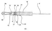
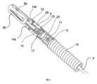
図5~7に示すように、シース装置2は、ハンドル1に接続される螺旋のシース19と、螺旋のシース19の遠位端に設置される接続管20とを含み、シース装置2が分離不能なユニットにされる。接続管20のシース19に対する接続方式により、接続管20がシース19に対してその縦方向の中心軸線回りに回動自在である。このために、接続管20をシース19に回動可能に接続するように、接続管20の外周面に環状溝21が設けられ、係合部材22がシース19に固定的に設置され、任意選択で、係合部材22がシース19に溶接され、係合部材が環状溝21に係合される。本実施形態において、係合部材22は保持スリーブに設置される環状部材と形成され、該保持スリーブがシース19に溶接される。上記の環状溝21も1つの別体の環状部材であり、その遠位端側の末端に環状凸部を有し、本出願では肩部とも呼ばれる。相応に、係合部材22の近位端の末端にも凸部が設けられ、上記の2種の凸部の係合関係により、接続管20がシース19に接続された後、その長手方向において固定されて運動できないとともに、その縦方向の中心軸線回りにシース19に対して回動できるように構成される。 As shown in FIGS. 5-7, the
図7及び図8に示すように、シース装置2は、クランプハウジング6の対向する両側に位置決めされるとともに弾性接続アームの形態である2つの接続素子23によってクランプハウジング6に接続される。具体的に、接続素子23の遠位端はクランプハウジング6に固定的に取り付けられ、接続素子23の自由近位端が係合部24と形成され、該係合部が接続管20の内周面に設けられた相応の係合手段25と係合することにより、クランプハウジング6がシース装置2に連結される。押入(嵌入)接続によりクランプハウジング6をシース装置2に接続し、クランプハウジング6の近位端がシース装置2の接続管20の遠位端に挿入/延伸する。図12に示すように、接続管20の重なり合ったセクションにおいて、シース装置2の係合手段25が貫通孔の形態に設けられ、クランプハウジング6に貫通孔に対応する孔26を設けることにより、接続素子23の係合部24が、孔26及びクランプハウジング6に通されて外へシース装置2の係合手段25に圧入されることにより、クランプハウジング6がシース装置2に接続される。 As shown in FIGS. 7 and 8, the
図13に示すように、接続素子23は内向きの凸起セクションを有する。また、接続素子23の遠位端は、径方向に外側に向かってクランプハウジング6に設けられた対応の保持孔27内まで延在し、任意選択で、溶接により保持孔に固定される。接続素子23は、接続素子23の遠位端に向かって延在するストレートセクション28をさらに有し、近位端方向に向かって観察する場合、該ストレートセクションが、クランプハウジングの縦方向の中心軸線に対して5°の傾斜角度で内側へ傾斜する。接続素子23のストレートセクション28と係合部24との間において、接続素子23の近位端の箇所に内向きの凸起セクション29が設けられる。 As shown in FIG. 13, connecting
図10に示すように、一実施形態において、クランプハウジング6と接続管20との接続を解除するための釈放機構が設置される。該釈放機構は、コントロールワイヤ4上に設置された突起部30を有する。突起部30は、接続素子23の内向きの凸起セクション29と協働するとともに該内向きの凸起セクションの間に位置し、内向きの凸起セクション29を弾性的に外へ押圧することにより、接続素子23が変形して、その自由端が押圧される。コントロールワイヤ4を近位端へ引っ張ることにより突起部30が接続素子23との係合から離脱すると、凸起セクション29がその弾性復元力で内向きに変形して元の形状になり、接続部24が接続管20の係合手段25との係合から外される。 As shown in FIG. 10, in one embodiment, a release mechanism is provided for disconnecting the clamp housing 6 and the connecting
使用時に、内視鏡によりクランプ装置3を目標部位まで送り、クランプ装置3を目標部位における所定位置で血管に固定する。血管をしっかりと挟むために、アクチュエータ5によりコントロールワイヤ4を遠位端方向及び近位端方向へ移動させることにより、クランプアーム8a、8bを繰り返して開閉させることができる。 In use, the
クランプ装置3をセットできたら、クランプアーム8a、8bをコントロールワイヤ4から分離させる。このために、図9に示すように、近位側方向へコントロールワイヤ4を引っ張って、クランプアーム8a、8bを完全に閉じて血管閉鎖位置に固定する。この図面に示すように、ガイド溝12は軸方向に延在するストレートな遠位端セクション12aを有し、ガイドピン13が、クランプアーム8a、8bの更なる回動にならないように該遠位端セクション12a内を移動可能である。ガイドピン13がガイド溝12の遠位端の先端位置に到達すると、クランプアーム8a、8bに設けられた保持凸部31によりガイドピンが該位置に固定/ロックされる。保持凸部31は、ガイド溝の側方からガイド溝12のストレートな遠位端セクション12a内まで延在するとともに、ガイドピン13がこれらの保持凸部31を通過してガイド溝12の遠位端まで到達することを許容するが、ガイドピン13の反対方向への通過を阻止するように構成された。具体的に、保持凸部31は、ガイドピン13が保持凸部31の近位端の側に押圧されるとき、保持凸部がガイド溝12の側面における凹部12bへ弾性変形して、ガイドピン13が保持凸部31を通過してガイド溝12の遠位端位置に到達することが許容され、ガイドピン13が最終位置に到達したとき、保持凸部がその弾性復元力によって元の形状に復元してガイドピン13の後方に係合され、ただし、ガイドピン13が保持凸部31の遠位端の側に押圧されるとき、ガイド溝12を再開放するように保持凸部が変形することができなく、ガイドピン13がガイド溝12の遠位端位置に拘束されるように構成される。したがって、クランプアーム8a、8bがクランプベース7に確実にロックされて、クランプハウジング6にロックされる。 After setting the
コントロールワイヤ4をさらに引き戻す場合、クランプアーム8a、8bの更なる移動が不能になり、そして、この場合、枢動ピン9が貫通孔の後側の出口通路15を通って貫通孔10から引き出される。該過程において、出口通路15の対向する両側に位置するクランプアーム8a、8bの尾端セクション16、17が塑性的に離間して、出口通路15が開放される。 If the
クランプハウジング6をシース装置2から分離/釈放するために、近位端方向へコントロールワイヤ4をさらに引き戻し、したがって、カップリングヘッド11の突起部30が接続素子23の内向きの凸起セクション29との係合から解除されて、接続素子23が、その自由端とシース装置2の接続管20の係合手段25との係合が解除されるように元の形状に復元される。In order to separate/release the clamp housing 6 from the
クランプアーム8a、8bの閉じる過程において、クランプアーム8a、8bの尾端が環状の肩部18の中央開口を通過してクランプベース7に進入し、クランプアームがクランプベース7の肩部18の後方に係合されて、クランプアーム8a、8bがクランプベース7にロックされる。 During the closing process of the
任意選択で、図2~9に示すように、本出願の各実施例による医療器具におけるクランプ装置3のクランプアーム8a、8bそれぞれに、少なくとも2つの歯状部材が設けられ、以下、側歯と称する。任意選択で、各側歯と、対応するクランプアーム8a、8bとが一体成形される。ここで、各側歯が歯頂と歯底とを有し、各クランプアームにおける側歯の数が同じである。任意選択で、片側のクランプアーム8aにおける各側歯と、もう片側のクランプアーム8bにおける各側歯とは、位置が対称で、歯の形状が逆になっている。また、例えば、クランプアームのそれぞれにおける少なくとも2つの側歯は、それぞれ該当クランプアームの軸線(即ち、長手方向の中心線)に対する両側に対称の位置で配置され、歯の形状が互いに逆になっている。ここで、片側のクランプアーム8aを例にする。図面に示すように、該クランプアームの軸線に対する左側の歯の形状が雄歯であり、右側の歯の形状が雌歯である。したがって、片側のクランプアーム8aをその軸線回りに180度回転させれば、もう片側のクランプアーム8bになることができる。このような設計を採用することにより、本出願によるクランプ装置3のクランプアーム8a、8bについて、1種の金型で両方のクランプアームも作製することができるので、製造プロセスが簡素化されて、製造コストを抑えることができる。各クランプアームに上記の側歯を設けることによれば、該医療器具は、生物組織をより確実につかむことができて、臨床止血や創傷閉鎖に使用する場合、操作がより安全でコントロール性に優れる。
Optionally, as shown in FIGS. 2-9, each of the clamping
本出願は、操作、製造及び組立に容易である組織止血又は組織閉鎖用の医療器具を提供する。本開示に係る医療器具によれば、クランプハウジング及びシース装置は相応の接続素子によって互いに直接接続され、接続素子がクランプハウジングに固定的に設置され、又はクランプハウジングの一部として形成され、シース装置に外し可能に接続される。このようにして、クランプハウジングとシース装置とは、確実且つ安定に接続することができて、本出願に係る医療器具は、設計構成が簡単で、製造が容易になる。 The present application provides a medical device for tissue hemostasis or tissue closure that is easy to operate, manufacture and assemble. According to the medical instrument according to the present disclosure, the clamping housing and the sheath device are directly connected to each other by corresponding connecting elements, the connecting elements being fixedly mounted on the clamping housing or formed as part of the clamping housing, and the sheath device is detachably connected to the In this way, the clamp housing and the sheath device can be reliably and stably connected, and the medical device according to the present application has a simple design configuration and is easy to manufacture.
1 ハンドル
2 シース装置
3 クランプ装置
4 コントロールワイヤ
5 アクチュエータ
6 クランプハウジング
7 クランプベース
8a、8b クランプアーム
9 枢動ピン
10 貫通孔
11 カップリングヘッド
12 ガイド溝
12a 遠位端セクション
12b 凹部
13 ガイドピン
14a、14b 軸受アーム
15 出口通路
16、17 尾端セクション
18 肩部
19 シース
20 接続管
21 環状溝
22 係合部材
23 接続素子
24 係合部
25 係合手段
26 孔
27 保持孔
28 ストレートセクション
29 凸起セクション
30 突起部
31 保持凸部
1 handle 2
Claims (20)
Translated fromJapaneseハンドル(1)に取り付けられるシース装置(2)と、
少なくとも2つのクランプアーム(8a、8b)と、クランプベース(7)を備えるクランプハウジング(6)とを備え、クランプベース(7)が、前記シース装置(2)の遠位端にセットされるスリーブの形態のものであるクランプ装置(3)と、
前記シース装置(2)を穿通して延在し、遠位端方向及び近位端方向に可逆的に移動可能であるコントロールワイヤ(4)と、
前記コントロールワイヤ(4)の近位端に連結され、前記コントロールワイヤ(4)を前記遠位端方向及び前記近位端方向に可逆的に移動させるように駆動されることができるアクチュエータ(5)と、
を備え、
前記クランプアーム(8a、8b)のそれぞれが前記コントロールワイヤ(4)の遠位端に連結され、
前記コントロールワイヤ(4)の前記近位端方向への移動が前記クランプアーム(8a、8b)の閉じる移動に変換され、前記コントロールワイヤ(4)の前記遠位端方向への移動が前記クランプアーム(8a、8b)の開放移動に変換されるように、前記コントロールワイヤ(4)の移動により、前記クランプ装置(3)の前記クランプアーム(8a、8b)が開閉駆動され、
前記クランプハウジング(6)が少なくとも1つの接続素子(23)により直接前記シース装置(2)に接続され、
各前記接続素子(23)が、前記クランプハウジング(6)に固定的に取り付けられ、又は前記クランプハウジング(6)の一部として形成され、前記シース装置(2)に外し可能に接続され、
各前記接続素子(23)と協働する釈放機構が設置され、前記クランプアーム(8a、8b)が閉じたとき、前記コントロールワイヤ(4)の前記近位端方向への移動により前記釈放機構が駆動されることにより、前記シース装置(2)から各前記接続素子(23)がリリースされて前記クランプハウジングが釈放され、
前記接続素子(23)は、弾性を有して弾性変形可能な接続アームで構成され、前記接続素子(23)の遠位端が前記クランプハウジング(6)に固定的に取り付けられ、前記接続素子(23)の自由近位端が、前記クランプハウジング(6)を前記シース装置(2)に接続するように前記シース装置(2)における相応の係合手段(25)と係合する係合部(24)として形成され、
押入接続により前記クランプハウジング(6)が前記シース装置(2)に接続されて、重なり合った部分が形成され、前記係合手段(25)が前記シース装置(2)の内周壁における凹部又は貫通孔で構成される
ことを特徴とする組織止血又は組織閉鎖用の医療器具。a handle (1);
a sheath device (2) attached to the handle (1);
comprising at least two clamping arms (8a, 8b) and a clamping housing (6) comprising a clamping base (7), the clamping base (7) being set at the distal end of said sheath device (2) a clamping device (3) in the form of a sleeve;
a control wire (4) extending through the sheath device (2) and reversibly movable distally and proximally;
an actuator (5) coupled to the proximal end of the control wire (4) and operable to reversibly move the control wire (4) in the distal and proximal directions; and,
with
each of said clamping arms (8a, 8b) being connected to a distal end of said control wire (4);
Movement of the control wire (4) towards the proximal end translates into closing movement of the clamp arms (8a, 8b) and movement of the control wire (4) towards the distal end of the clamp arm movement of the control wire (4) drives the clamping arms (8a, 8b) of the clamping device (3) to open and close, so as to be converted into opening movement of (8a, 8b);
said clamping housing (6) is directly connected to said sheath device (2) by at least one connecting element (23),
each said connecting element (23) being fixedly attached to said clamp housing (6) or formed as part ofsaid clamp housing (6) and releasably connected to said sheath device (2);
A release mechanism is provided cooperating with each said connecting element (23) such that when said clamping arms (8a, 8b) are closed, movement of said control wire (4) towards said proximal end releases said release mechanism. being actuated releases each said connecting element (23) from said sheath device (2) to release said clamping housing;
Said connecting element (23) consists of an elastic and elastically deformable connecting arm, a distal end of said connecting element (23) is fixedly attached to said clamping housing (6), said connecting element (23) (23) free proximal end engages with corresponding engagement means (25) on said sheath device (2) to connect said clamp housing (6) to said sheath device (2). (24) is formed as
A push-fit connection connects said clamp housing (6) to said sheath device (2) to form an overlapping portion, said engagement means (25) being recessed or through-holes in the inner peripheral wall of said sheath device (2). consists of
A medical device for tissue hemostasis or tissue closure, characterized in that:
ことを特徴とする請求項1に記載の医療器具。Said sheath device (2) comprises a sheath (19) and further comprises a connecting tube (20) located at the distal end of said sheath (19), said connecting tube (20) being connected to said sheath device (2). ) and the clamping device (3)
The medical device according to claim 1, characterized in that:
ことを特徴とする請求項2に記載の医療器具。3. A medical device according to claim 2, characterized in that the sheath (19) is of an extendable helix.
ことを特徴とする請求項3に記載の医療器具。4. Medical treatment according to claim 3, characterized in that the connecting tube (20) is connected to the sheath (19) so as to be pivotable relative to the sheath (19) about its longitudinal central axis. instrument.
ことを特徴とする請求項4に記載の医療器具。An annular groove (21) is provided on the outer peripheral surface of the connecting tube (20) so that the connecting tube (20) is connected to the sheath (19), and an engaging member (22) is fitted to the sheath (19). 5. A medical device according to claim 4, characterized in that it is fixedly mounted in a , and said engagement member is engaged in said annular groove (21).
ことを特徴とする請求項5に記載の医療器具。6. A device according to claim 5, characterized in that said engagement member (22) is welded to said sheath (19), said engagement member (22) engaging an annular shoulder of said annular groove (21). medical instruments.
ことを特徴とする請求項1~6のいずれか1項に記載の医療器具。Claims1 to 6 , characterized in that at least two said connecting elements (23) are provided, said connecting elements being positioned offset by a defined angle along the circumference of said clamping housing (6). The medical device according to any one of Claims 1 to 3.
ことを特徴とする請求項7に記載の医療器具。8. Medical instrument according to claim 7, characterized in that two connecting elements (23) are provided, said connecting elements being located on opposite sides of said clamping housing (6) respectively.
ことを特徴とする請求項8に記載の医療器具。Said release mechanism comprises a projection (30), said projection being arranged between and cooperating withsaidtwo connecting elements (23), said projection (30) being connected to said connecting element. By pressing the element (23), the connecting element is elastically deformed outwards and the engaging portion (24) of the connecting element (23) is pushed outwards to correspondingly engage the sheath device (2). The clamping housing (6) is connected to the sheath device (2) by engaging means (25 ) and the projection (30) iscoupled to the control wire (4), After the clamping arms (8a, 8b) are closed, further movement of the control wire (4) towards the proximal end causesthe protrusion (30) to move with the control wire (4) to remove the connecting element. (23), the connecting element is deformed inwardly by its elastic restoring force so that the engaging portion (24) of the connecting element (23) is correspondingly engaged with the sheath device (2). 9. A medical instrument according to claim 8, characterized in that disengagement with mating means (25) releases the clamping housing (6) from the sheath device (2).
ことを特徴とする請求項9に記載の医療器具。Said connection element (23) is provided with a raised section (29), said raised section is provided at the free end of said connection element (23), and said projection (30) connects saidtwo connections. disposed between said raised sections (29) of elements (23) and cooperating with said raised sections to deform said connecting element (23) outwardly, said protrusions (30) being displaced; 10. Medical device according to claim 9, characterized in that when disengaged from the raised section (29), the connecting element (23) deforms inwards due to its elastic restoring force.
ことを特徴とする請求項10に記載の医療器具。The proximal end of said clamp housing (6) is inserted into the distal end of said sheath device (2), said engagement portion (24) of said connecting element (23)being an outward finger engagement portion. 11. The medical device of claim10 , wherein the medical device is formedby
ことを特徴とする請求項11に記載の医療器具。Said engagement means (25 ) and corresponding holes (26) of said sheath device (2) are adapted to connect said clamp housing (6) to said sheath device (2). It is installed in the overlapping part with the clamp housing (6), and the engaging part (24) of the connecting element (23) is pushed outward through the hole (26) in the clamp housing (6). 12. A medical device according to claim11 , characterized in that it is pressed into the engagement means (25) of the sheath device (2).
ことを特徴とする請求項9~12のいずれか1項に記載の医療器具。Said connecting element (23) has a straight section (28) which, when viewed towards said proximal end, slopes inwards with respect to the longitudinal central axis of said clamping housing (6).do
The medical device according to any one of claims 9 to12 , characterized in that:
ことを特徴とする請求項1に記載の医療器具。The distal end of the connecting element (23) extends radially outwards into a corresponding retaining hole (27) provided in the clamping housing (6) and is welded into the retaining hole. 2. The medical device of claim1 , wherein the medical device is stationary.
ことを特徴とする請求項14に記載の医療器具。The clamping housing (6) has two bearing arms (14a, 14b) extending from the clamping base (7) in the distal direction, the connecting element (23) extending from the free ends of the bearing arms. fixedly attached to said bearing arms (14a, 14b) in sections, between said two bearing arms (14a, 14b) a guide pin (13) is held and said connecting element (23) is connected to said guide 15. Medical device according to claim14 , characterized in that it is placed on theproximal side of the pin (13).
ことを特徴とする請求項1~15のいずれか1項に記載の医療器具。Each said clamping arm (8a, 8b) is provided with at least two side teeth respectively, and at least two side teeth on one side of said clamping arm (8a, 8b) are arranged in symmetrical positions on both sides with respect to said clamping arm axis. 16. The medical device according to any one ofclaims1 to 15, characterized in that the tooth shapes are opposite to each other.
2つの前記クランプアーム(8a、8b)が、互いに別体の素子として構成され、各前記クランプアームが枢動ピン(9)によって規定された共通の枢動軸線回りに枢動可能に前記コントロールワイヤ(4)の遠位端に連結され、各前記クランプアーム(8a、8b)のそれぞれにガイド溝(12)が設けられ、2つの前記クランプアーム(8a、8b)の前記ガイド溝(12)が部分的に重なり合い、
前記ガイドピン(13)が前記クランプハウジング(6)に取り付けられるとともに前記ガイド溝(12)の重なり合った部分を穿通して延在し、前記ガイドピン(13)と前記ガイド溝(12)との係合により、前記コントロールワイヤ(4)の前記近位端方向への移動が前記クランプアーム(8a、8b)の閉じる移動に変換され、前記コントロールワイヤ(4)の前記遠位端方向への移動が前記クランプアーム(8a、8b)の前記枢動軸線回りの開放移動に変換される
ことを特徴とする請求項1~14のいずれか1項に記載の医療器具。said clamping device (3) comprises twosaid clamping arms (8a, 8b) and a guide pin (13),
Twosaid clamping arms(8a, 8b) are constructed as separate elements from each other, eachsaid clamping arm being pivotable about a common pivot axis defined by a pivot pin (9) to said control wire. (4),each clamp arm (8a, 8b) is provided with a guide groove (12), and the guide groove (12) ofthe two clamp arms (8a, 8b) is partially overlapping,
The guide pin (13) is attached to the clamp housing (6) andextends through the overlapped portion of the guide groove (12) to form a gap between the guide pin (13) and the guide groove (12). Engagement translates movement of the control wire (4) towards the proximal end into a closing movement of the clamp arms (8a, 8b) and movement of the control wire (4) towards the distal end.is translated into an opening movement of the clamping arms (8a, 8b) about the pivot axis.
ことを特徴とする請求項17に記載の医療器具。Said guide pin (13) is held between two bearing arms (14a, 14b) extending from said clamp housing (6) in the distal direction, and the freedom of said bearing arms (14a, 14b). 18. The medical device of claim17 , retained in the end section.
ことを特徴とする請求項17又は18に記載の医療器具。A holding protrusion (31) is provided on the clamp arms (8a, 8b), and the holding protrusion (31) extends from the side surface of the guide groove to the inside of the guide groove (12). (13) to pass through the holding protrusion to reach the distal end of the guide groove (12), but to prevent the passage of the guide pin (13) in the opposite direction., said guide groove (12) has an axially extending straight distal end section (12a) and said guide pin (13) is prevented from pivoting of said clamping arms (8a, 8b). 19. According to claim17 or18 , characterized in that said retaining projection( 31) extends into said straightdistal end section (12a). Medical device as described.
ことを特徴とする請求項19に記載の医療器具。A concave portion (12b) is formed on the side surface of the guide groove (12) on the distal end side of the holding projection (31), and the guide pin (13) passes through the holding projection (31) to 20. The method according to claim19 , characterized in that said retaining projection (31) can be elastically deformed into said recess (12b) so as to allow reaching the distal end position of the guide groove (12). medical instruments.
Applications Claiming Priority (3)
| Application Number | Priority Date | Filing Date | Title |
|---|---|---|---|
| EP19185556.8AEP3763298B1 (en) | 2019-07-10 | 2019-07-10 | Medical device for causing the hemostasis of a blood vessel |
| EP19185556.8 | 2019-07-10 | ||
| PCT/CN2020/084280WO2021004107A1 (en) | 2019-07-10 | 2020-04-10 | Medical instrument for tissue hemostasis or closure |
Publications (2)
| Publication Number | Publication Date |
|---|---|
| JP2022526402A JP2022526402A (en) | 2022-05-24 |
| JP7268190B2true JP7268190B2 (en) | 2023-05-02 |
Family
ID=67226176
Family Applications (1)
| Application Number | Title | Priority Date | Filing Date |
|---|---|---|---|
| JP2021558877AActiveJP7268190B2 (en) | 2019-07-10 | 2020-04-10 | Medical devices for tissue hemostasis or tissue closure |
Country Status (8)
| Country | Link |
|---|---|
| US (1) | US12070225B2 (en) |
| EP (1) | EP3763298B1 (en) |
| JP (1) | JP7268190B2 (en) |
| KR (1) | KR102678260B1 (en) |
| CN (2) | CN117883143A (en) |
| AU (1) | AU2020311418B2 (en) |
| CA (1) | CA3134416A1 (en) |
| WO (1) | WO2021004107A1 (en) |
Families Citing this family (13)
| Publication number | Priority date | Publication date | Assignee | Title |
|---|---|---|---|---|
| US12167857B2 (en)* | 2019-04-17 | 2024-12-17 | Micro-Tech (Nanjing) Co., Ltd. | Clamp device for hemostasis or closure of tissue and medical instrument for hemostasis or closure of tissue |
| EP3763298B1 (en)* | 2019-07-10 | 2023-11-29 | Micro-Tech (Nanjing) Co., Ltd. | Medical device for causing the hemostasis of a blood vessel |
| EP3725242B1 (en)* | 2019-04-17 | 2023-11-29 | Micro-Tech (Nanjing) Co., Ltd. | Medical device for causing the hemostasis of a blood vessel |
| CN115103641A (en) | 2019-11-01 | 2022-09-23 | 康美公司 | Apparatus and method for applying a hemostatic clip assembly |
| CA3156881A1 (en) | 2019-11-01 | 2021-05-06 | Doug SJOSTROM | Devices and methods for applying a hemostatic clip assembly |
| CN118576267A (en)* | 2020-06-12 | 2024-09-03 | 南微医学科技股份有限公司 | A clamp with high grip and low release force |
| EP4225162A1 (en)* | 2020-10-08 | 2023-08-16 | Conmed Corporation | Devices and methods for applying a hemostatic clip assembly |
| DE212022000341U1 (en)* | 2022-02-25 | 2024-08-07 | Micro-Tech (Nanjing) Co., Ltd. | Medical device for stopping bleeding in a blood vessel |
| CN222870566U (en)* | 2022-02-25 | 2025-05-16 | 南微医学科技股份有限公司 | Medical instrument for hemostasis of blood vessels |
| WO2023159521A1 (en)* | 2022-02-25 | 2023-08-31 | Micro-Tech (Nanjing) Co., Ltd. | Medical device for causing hemostasis of blood vessel |
| WO2023186258A1 (en)* | 2022-03-28 | 2023-10-05 | Clearstream Technologies Limited | Delivery systems for implants |
| CN116473608B (en)* | 2022-12-28 | 2025-07-08 | 杭州圣石科技股份有限公司 | A split left atrial appendage closure clip system |
| CN116115288B (en)* | 2023-03-10 | 2024-03-12 | 江苏唯德康医疗科技有限公司 | Hemostatic clamp assembly and hemostatic clamp comprising same |
Citations (4)
| Publication number | Priority date | Publication date | Assignee | Title |
|---|---|---|---|---|
| JP2005505337A (en) | 2001-10-05 | 2005-02-24 | ボストン サイエンティフィック リミテッド | Scope Endoscopic hemostatic clip device |
| US20140074131A1 (en) | 2010-01-29 | 2014-03-13 | Advanced Bariatric Technology, Llc | Surgical clamp and surgical clamp installation tool |
| CN109805977A (en) | 2019-03-21 | 2019-05-28 | 南京微创医学科技股份有限公司 | A kind of Medical hemostatic clamp |
| CN109953800A (en) | 2019-05-05 | 2019-07-02 | 南京微创医学科技股份有限公司 | A kind of chute-type multi-arm folder |
Family Cites Families (40)
| Publication number | Priority date | Publication date | Assignee | Title |
|---|---|---|---|---|
| US5496333A (en) | 1993-10-20 | 1996-03-05 | Applied Medical Resources Corporation | Laparoscopic surgical clamp |
| US7494461B2 (en)* | 2003-09-30 | 2009-02-24 | Boston Scientific Scimed, Inc. | Through the scope tension member release clip |
| AU2004289214B2 (en)* | 2003-11-07 | 2011-05-19 | Scimed Life Systems, Inc. | Endoscopic hemoscopic clipping apparatus |
| JP4758173B2 (en) | 2004-12-24 | 2011-08-24 | オリンパス株式会社 | Ligation device |
| JP5244816B2 (en)* | 2006-12-05 | 2013-07-24 | クック メディカル テクノロジーズ エルエルシー | Combination therapy hemostatic clip |
| US8162959B2 (en) | 2007-05-03 | 2012-04-24 | Boston Scientific Scimed, Inc. | Single stage hemostasis clipping device |
| JP5006753B2 (en)* | 2007-10-17 | 2012-08-22 | Hoya株式会社 | Endoscopic clip device |
| EP2467069A1 (en) | 2009-08-19 | 2012-06-27 | Boston Scientific Scimed, Inc. | Multifunctional core for two-piece hemostasis clip |
| JP5486983B2 (en) | 2010-03-29 | 2014-05-07 | 富士フイルム株式会社 | Ligation device |
| CN103200883B (en) | 2010-10-11 | 2015-08-26 | 库克医学技术有限责任公司 | Medical device with removable pivotable jaws |
| EP2627264B1 (en) | 2010-10-11 | 2015-06-17 | Cook Medical Technologies LLC | Medical devices with detachable pivotable jaws |
| CN102090910B (en) | 2011-03-03 | 2012-12-19 | 柏峻峰 | Biological tissue clamp |
| WO2013067662A1 (en)* | 2011-11-11 | 2013-05-16 | Zhu Jian | Clamping or ligating device |
| CN102626335B (en)* | 2012-04-16 | 2014-04-09 | 常州市久虹医疗器械有限公司 | Hemostatic clamp with four-bar structure |
| CN202699217U (en) | 2012-05-28 | 2013-01-30 | 杭州安杰思医学科技有限公司 | Hemostasis clamp capable of being repeatedly opened and closed and provided with pusher |
| CN202699218U (en) | 2012-07-05 | 2013-01-30 | 安瑞医疗器械(杭州)有限公司 | Tissue hemostasis clamping device |
| US20140088616A1 (en) | 2012-09-24 | 2014-03-27 | Boston Scientific Scimed, Inc. | Release mechanism for hemostatic clip |
| CN203828993U (en)* | 2014-05-23 | 2014-09-17 | 南京微创医学科技有限公司 | Hemostatic clip |
| CN103989500B (en) | 2014-05-23 | 2015-11-18 | 南京微创医学科技有限公司 | A kind of hemostatic clamp |
| CN206482631U (en) | 2016-03-18 | 2017-09-12 | 杭州光典医疗器械有限公司 | A kind of not damaged clamp of Minimally Invasive Surgery nipper |
| CN105935304B (en) | 2016-03-30 | 2018-05-04 | 北京龙淼医疗器械有限公司 | A kind of hemostatic clamp |
| US10799358B2 (en)* | 2016-04-12 | 2020-10-13 | Lars Erickson | Catheter system for selectively manipulating and connecting cardiac tissues |
| EP3487422B1 (en)* | 2016-08-22 | 2021-11-03 | Boston Scientific Limited | Hemostasis reloadable clipping device with sleeve engagement |
| CN206239447U (en) | 2016-08-31 | 2017-06-13 | 张龙 | A kind of single use can single armed folding clip |
| DE202017007425U1 (en)* | 2016-09-22 | 2021-06-11 | Boston Scientific Limited | Multiple opening / closing of a clip |
| EP3457953A1 (en)* | 2016-09-29 | 2019-03-27 | Boston Scientific Limited | Sacrificial coupler for reloadable hemostasis clipping device |
| WO2018106710A1 (en)* | 2016-12-06 | 2018-06-14 | Boston Scientific Scimed, Inc. | Compressive coupler for reloadable hemostasis clipping device |
| CN107115130B (en)* | 2017-04-20 | 2020-05-19 | 南微医学科技股份有限公司 | Double-sliding-groove self-locking hemostatic clamp |
| JP6815506B2 (en) | 2017-06-21 | 2021-01-20 | 富士フイルム株式会社 | Clip treatment tool |
| CN109199515B (en) | 2017-07-05 | 2020-10-09 | 江苏风和医疗器材股份有限公司 | Vascular clamp |
| CN107684448A (en) | 2017-09-29 | 2018-02-13 | 苏州朗特斯医疗科技有限公司 | A kind of hemostatic clamp |
| CN208435704U (en) | 2017-09-29 | 2019-01-29 | 苏州朗特斯医疗科技有限公司 | A kind of hemostatic clamp |
| CN108635007B (en)* | 2018-05-22 | 2024-01-05 | 杭州丽康医学科技股份有限公司 | Disposable repeatable opening and closing endoscope hemostatic clamp |
| CN109009310A (en) | 2018-06-07 | 2018-12-18 | 诸暨市鹏天医疗器械有限公司 | A kind of Endoscope hemostasis folder |
| CN109480950B (en) | 2018-12-27 | 2024-10-25 | 扬州发特利医疗器械科技有限公司 | Clip device for endoscope |
| CN209884245U (en)* | 2019-03-21 | 2020-01-03 | 南微医学科技股份有限公司 | Medical hemostatic clamp |
| EP3763298B1 (en)* | 2019-07-10 | 2023-11-29 | Micro-Tech (Nanjing) Co., Ltd. | Medical device for causing the hemostasis of a blood vessel |
| EP3725242B1 (en)* | 2019-04-17 | 2023-11-29 | Micro-Tech (Nanjing) Co., Ltd. | Medical device for causing the hemostasis of a blood vessel |
| US12167857B2 (en)* | 2019-04-17 | 2024-12-17 | Micro-Tech (Nanjing) Co., Ltd. | Clamp device for hemostasis or closure of tissue and medical instrument for hemostasis or closure of tissue |
| US11857213B2 (en)* | 2020-08-28 | 2024-01-02 | Gyrus Acmi, Inc. | Forceps with hinged jaws and force distribution |
- 2019
- 2019-07-10EPEP19185556.8Apatent/EP3763298B1/enactiveActive
- 2020
- 2020-04-10CNCN202410028074.XApatent/CN117883143A/enactivePending
- 2020-04-10CACA3134416Apatent/CA3134416A1/enactivePending
- 2020-04-10USUS17/441,397patent/US12070225B2/enactiveActive
- 2020-04-10KRKR1020217036304Apatent/KR102678260B1/enactiveActive
- 2020-04-10WOPCT/CN2020/084280patent/WO2021004107A1/ennot_activeCeased
- 2020-04-10JPJP2021558877Apatent/JP7268190B2/enactiveActive
- 2020-04-10AUAU2020311418Apatent/AU2020311418B2/enactiveActive
- 2020-04-10CNCN202080029617.XApatent/CN113784671B/enactiveActive
Patent Citations (4)
| Publication number | Priority date | Publication date | Assignee | Title |
|---|---|---|---|---|
| JP2005505337A (en) | 2001-10-05 | 2005-02-24 | ボストン サイエンティフィック リミテッド | Scope Endoscopic hemostatic clip device |
| US20140074131A1 (en) | 2010-01-29 | 2014-03-13 | Advanced Bariatric Technology, Llc | Surgical clamp and surgical clamp installation tool |
| CN109805977A (en) | 2019-03-21 | 2019-05-28 | 南京微创医学科技股份有限公司 | A kind of Medical hemostatic clamp |
| CN109953800A (en) | 2019-05-05 | 2019-07-02 | 南京微创医学科技股份有限公司 | A kind of chute-type multi-arm folder |
Also Published As
| Publication number | Publication date |
|---|---|
| EP3763298A1 (en) | 2021-01-13 |
| WO2021004107A1 (en) | 2021-01-14 |
| AU2020311418A1 (en) | 2021-10-21 |
| KR102678260B1 (en) | 2024-06-26 |
| EP3763298C0 (en) | 2023-11-29 |
| US12070225B2 (en) | 2024-08-27 |
| CN117883143A (en) | 2024-04-16 |
| CN113784671A (en) | 2021-12-10 |
| AU2020311418B2 (en) | 2022-12-15 |
| EP3763298B1 (en) | 2023-11-29 |
| KR20210147062A (en) | 2021-12-06 |
| CA3134416A1 (en) | 2021-01-14 |
| JP2022526402A (en) | 2022-05-24 |
| CN113784671B (en) | 2024-01-26 |
| US20220167990A1 (en) | 2022-06-02 |
Similar Documents
| Publication | Publication Date | Title |
|---|---|---|
| JP7268190B2 (en) | Medical devices for tissue hemostasis or tissue closure | |
| JP7269365B2 (en) | Medical devices for tissue hemostasis or tissue closure | |
| EP1670365B1 (en) | Apparatus for deployment of a hemostatic clip | |
| EP2380509B1 (en) | Apparatus for deployment of a hemostatic clip | |
| CN217793203U (en) | Clamping devices and medical devices for hemostasis or closure of tissue | |
| CN111526804A (en) | Dual support jaw design | |
| CN216876472U (en) | Medical device for tissue hemostasis or closure | |
| JP3249585U (en) | Medical devices for vascular hemostasis | |
| JP3250413U (en) | Medical devices for vascular hemostasis | |
| AU2021105991A4 (en) | Clamp device for hemostasis or closure of tissue and medical instrument for hemostasis or closure of tissue | |
| WO2025162363A1 (en) | Clip instrument and operation method therefor |
Legal Events
| Date | Code | Title | Description |
|---|---|---|---|
| A621 | Written request for application examination | Free format text:JAPANESE INTERMEDIATE CODE: A621 Effective date:20211001 | |
| A977 | Report on retrieval | Free format text:JAPANESE INTERMEDIATE CODE: A971007 Effective date:20220930 | |
| A131 | Notification of reasons for refusal | Free format text:JAPANESE INTERMEDIATE CODE: A131 Effective date:20221011 | |
| A521 | Request for written amendment filed | Free format text:JAPANESE INTERMEDIATE CODE: A523 Effective date:20230110 | |
| TRDD | Decision of grant or rejection written | ||
| A01 | Written decision to grant a patent or to grant a registration (utility model) | Free format text:JAPANESE INTERMEDIATE CODE: A01 Effective date:20230411 | |
| A61 | First payment of annual fees (during grant procedure) | Free format text:JAPANESE INTERMEDIATE CODE: A61 Effective date:20230420 | |
| R150 | Certificate of patent or registration of utility model | Ref document number:7268190 Country of ref document:JP Free format text:JAPANESE INTERMEDIATE CODE: R150 |