JP7268073B2 - vehicle display - Google Patents
vehicle displayDownload PDFInfo
- Publication number
- JP7268073B2 JP7268073B2JP2021036796AJP2021036796AJP7268073B2JP 7268073 B2JP7268073 B2JP 7268073B2JP 2021036796 AJP2021036796 AJP 2021036796AJP 2021036796 AJP2021036796 AJP 2021036796AJP 7268073 B2JP7268073 B2JP 7268073B2
- Authority
- JP
- Japan
- Prior art keywords
- display
- state
- transmittance
- light
- content
- Prior art date
- Legal status (The legal status is an assumption and is not a legal conclusion. Google has not performed a legal analysis and makes no representation as to the accuracy of the status listed.)
- Active
Links
Images


Classifications
- G—PHYSICS
- G02—OPTICS
- G02B—OPTICAL ELEMENTS, SYSTEMS OR APPARATUS
- G02B27/00—Optical systems or apparatus not provided for by any of the groups G02B1/00 - G02B26/00, G02B30/00
- G02B27/01—Head-up displays
- G02B27/0101—Head-up displays characterised by optical features
- B—PERFORMING OPERATIONS; TRANSPORTING
- B60—VEHICLES IN GENERAL
- B60K—ARRANGEMENT OR MOUNTING OF PROPULSION UNITS OR OF TRANSMISSIONS IN VEHICLES; ARRANGEMENT OR MOUNTING OF PLURAL DIVERSE PRIME-MOVERS IN VEHICLES; AUXILIARY DRIVES FOR VEHICLES; INSTRUMENTATION OR DASHBOARDS FOR VEHICLES; ARRANGEMENTS IN CONNECTION WITH COOLING, AIR INTAKE, GAS EXHAUST OR FUEL SUPPLY OF PROPULSION UNITS IN VEHICLES
- B60K35/00—Instruments specially adapted for vehicles; Arrangement of instruments in or on vehicles
- B60K35/20—Output arrangements, i.e. from vehicle to user, associated with vehicle functions or specially adapted therefor
- B60K35/21—Output arrangements, i.e. from vehicle to user, associated with vehicle functions or specially adapted therefor using visual output, e.g. blinking lights or matrix displays
- B60K35/22—Display screens
- B—PERFORMING OPERATIONS; TRANSPORTING
- B60—VEHICLES IN GENERAL
- B60K—ARRANGEMENT OR MOUNTING OF PROPULSION UNITS OR OF TRANSMISSIONS IN VEHICLES; ARRANGEMENT OR MOUNTING OF PLURAL DIVERSE PRIME-MOVERS IN VEHICLES; AUXILIARY DRIVES FOR VEHICLES; INSTRUMENTATION OR DASHBOARDS FOR VEHICLES; ARRANGEMENTS IN CONNECTION WITH COOLING, AIR INTAKE, GAS EXHAUST OR FUEL SUPPLY OF PROPULSION UNITS IN VEHICLES
- B60K35/00—Instruments specially adapted for vehicles; Arrangement of instruments in or on vehicles
- B60K35/20—Output arrangements, i.e. from vehicle to user, associated with vehicle functions or specially adapted therefor
- B60K35/21—Output arrangements, i.e. from vehicle to user, associated with vehicle functions or specially adapted therefor using visual output, e.g. blinking lights or matrix displays
- B60K35/23—Head-up displays [HUD]
- B—PERFORMING OPERATIONS; TRANSPORTING
- B60—VEHICLES IN GENERAL
- B60K—ARRANGEMENT OR MOUNTING OF PROPULSION UNITS OR OF TRANSMISSIONS IN VEHICLES; ARRANGEMENT OR MOUNTING OF PLURAL DIVERSE PRIME-MOVERS IN VEHICLES; AUXILIARY DRIVES FOR VEHICLES; INSTRUMENTATION OR DASHBOARDS FOR VEHICLES; ARRANGEMENTS IN CONNECTION WITH COOLING, AIR INTAKE, GAS EXHAUST OR FUEL SUPPLY OF PROPULSION UNITS IN VEHICLES
- B60K2360/00—Indexing scheme associated with groups B60K35/00 or B60K37/00 relating to details of instruments or dashboards
- B60K2360/1523—Matrix displays
- B—PERFORMING OPERATIONS; TRANSPORTING
- B60—VEHICLES IN GENERAL
- B60K—ARRANGEMENT OR MOUNTING OF PROPULSION UNITS OR OF TRANSMISSIONS IN VEHICLES; ARRANGEMENT OR MOUNTING OF PLURAL DIVERSE PRIME-MOVERS IN VEHICLES; AUXILIARY DRIVES FOR VEHICLES; INSTRUMENTATION OR DASHBOARDS FOR VEHICLES; ARRANGEMENTS IN CONNECTION WITH COOLING, AIR INTAKE, GAS EXHAUST OR FUEL SUPPLY OF PROPULSION UNITS IN VEHICLES
- B60K2360/00—Indexing scheme associated with groups B60K35/00 or B60K37/00 relating to details of instruments or dashboards
- B60K2360/20—Optical features of instruments
- B60K2360/23—Optical features of instruments using reflectors
- B—PERFORMING OPERATIONS; TRANSPORTING
- B60—VEHICLES IN GENERAL
- B60K—ARRANGEMENT OR MOUNTING OF PROPULSION UNITS OR OF TRANSMISSIONS IN VEHICLES; ARRANGEMENT OR MOUNTING OF PLURAL DIVERSE PRIME-MOVERS IN VEHICLES; AUXILIARY DRIVES FOR VEHICLES; INSTRUMENTATION OR DASHBOARDS FOR VEHICLES; ARRANGEMENTS IN CONNECTION WITH COOLING, AIR INTAKE, GAS EXHAUST OR FUEL SUPPLY OF PROPULSION UNITS IN VEHICLES
- B60K2360/00—Indexing scheme associated with groups B60K35/00 or B60K37/00 relating to details of instruments or dashboards
- B60K2360/20—Optical features of instruments
- B60K2360/33—Illumination features
- B60K2360/349—Adjustment of brightness
- B—PERFORMING OPERATIONS; TRANSPORTING
- B60—VEHICLES IN GENERAL
- B60K—ARRANGEMENT OR MOUNTING OF PROPULSION UNITS OR OF TRANSMISSIONS IN VEHICLES; ARRANGEMENT OR MOUNTING OF PLURAL DIVERSE PRIME-MOVERS IN VEHICLES; AUXILIARY DRIVES FOR VEHICLES; INSTRUMENTATION OR DASHBOARDS FOR VEHICLES; ARRANGEMENTS IN CONNECTION WITH COOLING, AIR INTAKE, GAS EXHAUST OR FUEL SUPPLY OF PROPULSION UNITS IN VEHICLES
- B60K2360/00—Indexing scheme associated with groups B60K35/00 or B60K37/00 relating to details of instruments or dashboards
- B60K2360/40—Hardware adaptations for dashboards or instruments
- B60K2360/48—Sensors
- B—PERFORMING OPERATIONS; TRANSPORTING
- B60—VEHICLES IN GENERAL
- B60K—ARRANGEMENT OR MOUNTING OF PROPULSION UNITS OR OF TRANSMISSIONS IN VEHICLES; ARRANGEMENT OR MOUNTING OF PLURAL DIVERSE PRIME-MOVERS IN VEHICLES; AUXILIARY DRIVES FOR VEHICLES; INSTRUMENTATION OR DASHBOARDS FOR VEHICLES; ARRANGEMENTS IN CONNECTION WITH COOLING, AIR INTAKE, GAS EXHAUST OR FUEL SUPPLY OF PROPULSION UNITS IN VEHICLES
- B60K2360/00—Indexing scheme associated with groups B60K35/00 or B60K37/00 relating to details of instruments or dashboards
- B60K2360/77—Instrument locations other than the dashboard
- B60K2360/785—Instrument locations other than the dashboard on or in relation to the windshield or windows
- B—PERFORMING OPERATIONS; TRANSPORTING
- B60—VEHICLES IN GENERAL
- B60K—ARRANGEMENT OR MOUNTING OF PROPULSION UNITS OR OF TRANSMISSIONS IN VEHICLES; ARRANGEMENT OR MOUNTING OF PLURAL DIVERSE PRIME-MOVERS IN VEHICLES; AUXILIARY DRIVES FOR VEHICLES; INSTRUMENTATION OR DASHBOARDS FOR VEHICLES; ARRANGEMENTS IN CONNECTION WITH COOLING, AIR INTAKE, GAS EXHAUST OR FUEL SUPPLY OF PROPULSION UNITS IN VEHICLES
- B60K35/00—Instruments specially adapted for vehicles; Arrangement of instruments in or on vehicles
- B60K35/50—Instruments characterised by their means of attachment to or integration in the vehicle
- B—PERFORMING OPERATIONS; TRANSPORTING
- B60—VEHICLES IN GENERAL
- B60K—ARRANGEMENT OR MOUNTING OF PROPULSION UNITS OR OF TRANSMISSIONS IN VEHICLES; ARRANGEMENT OR MOUNTING OF PLURAL DIVERSE PRIME-MOVERS IN VEHICLES; AUXILIARY DRIVES FOR VEHICLES; INSTRUMENTATION OR DASHBOARDS FOR VEHICLES; ARRANGEMENTS IN CONNECTION WITH COOLING, AIR INTAKE, GAS EXHAUST OR FUEL SUPPLY OF PROPULSION UNITS IN VEHICLES
- B60K35/00—Instruments specially adapted for vehicles; Arrangement of instruments in or on vehicles
- B60K35/60—Instruments characterised by their location or relative disposition in or on vehicles
- B—PERFORMING OPERATIONS; TRANSPORTING
- B60—VEHICLES IN GENERAL
- B60K—ARRANGEMENT OR MOUNTING OF PROPULSION UNITS OR OF TRANSMISSIONS IN VEHICLES; ARRANGEMENT OR MOUNTING OF PLURAL DIVERSE PRIME-MOVERS IN VEHICLES; AUXILIARY DRIVES FOR VEHICLES; INSTRUMENTATION OR DASHBOARDS FOR VEHICLES; ARRANGEMENTS IN CONNECTION WITH COOLING, AIR INTAKE, GAS EXHAUST OR FUEL SUPPLY OF PROPULSION UNITS IN VEHICLES
- B60K35/00—Instruments specially adapted for vehicles; Arrangement of instruments in or on vehicles
- B60K35/80—Arrangements for controlling instruments
- B60K35/81—Arrangements for controlling instruments for controlling displays
- G—PHYSICS
- G02—OPTICS
- G02B—OPTICAL ELEMENTS, SYSTEMS OR APPARATUS
- G02B27/00—Optical systems or apparatus not provided for by any of the groups G02B1/00 - G02B26/00, G02B30/00
- G02B27/01—Head-up displays
- G02B27/0101—Head-up displays characterised by optical features
- G02B2027/014—Head-up displays characterised by optical features comprising information/image processing systems
- G—PHYSICS
- G02—OPTICS
- G02B—OPTICAL ELEMENTS, SYSTEMS OR APPARATUS
- G02B27/00—Optical systems or apparatus not provided for by any of the groups G02B1/00 - G02B26/00, G02B30/00
- G02B27/01—Head-up displays
- G02B27/0101—Head-up displays characterised by optical features
- G02B2027/0141—Head-up displays characterised by optical features characterised by the informative content of the display
Landscapes
- Engineering & Computer Science (AREA)
- Physics & Mathematics (AREA)
- Chemical & Material Sciences (AREA)
- Combustion & Propulsion (AREA)
- Transportation (AREA)
- Mechanical Engineering (AREA)
- General Physics & Mathematics (AREA)
- Optics & Photonics (AREA)
- Instrument Panels (AREA)
- Controls And Circuits For Display Device (AREA)
Description
Translated fromJapanese本発明は、車両用表示装置に関する。 The present invention relates to a vehicle display device.
従来、自動車等の車両には、ヘッドアップディスプレイ(HUD:Head Up Display)装置を搭載するものがある。ヘッドアップディスプレイ装置は、表示器に表示される表示画像を、反射ミラー等を介してウインドシールドまたはコンバイナに投影することで、ドライバに虚像として視認させるものである。ヘッドアップディスプレイ装置では、筐体内の表示器に表示された表示画像を筐体外のウインドシールド等に投影させる場合、筐体の上部に開口を設けている(例えば、特許文献1参照)。 2. Description of the Related Art Conventionally, some vehicles such as automobiles are equipped with a head-up display (HUD: Head Up Display) device. A head-up display device projects a display image displayed on a display onto a windshield or a combiner via a reflecting mirror or the like, thereby allowing a driver to view the image as a virtual image. 2. Description of the Related Art In a head-up display device, an opening is provided in the upper part of a housing when projecting a display image displayed on a display device inside the housing onto a windshield or the like outside the housing (see, for example, Patent Document 1).
ところで、太陽光等が外部から開口を介して内部に入射し、反射ミラー等を介して表示器に到達すると、反射ミラー等の集光作用により表示器の温度が上昇し、表示器の性能や耐久性が低下するおそれがあることから改善の余地がある。 By the way, when sunlight or the like enters the inside through the opening from the outside and reaches the display via the reflecting mirror, etc., the temperature of the display rises due to the light collecting action of the reflecting mirror, etc., and the performance of the display deteriorates. There is room for improvement since there is a possibility that the durability may be lowered.
本発明は、上記課題に鑑みて成されたものであり、外光による表示器の温度上昇を抑制する車両用表示装置を提供することを目的とする。 SUMMARY OF THE INVENTION It is an object of the present invention to provide a vehicular display device that suppresses temperature rise of a display device due to external light.
上記目的を達成するために、本発明に係る車両用表示装置は、車両用表示装置の外部に設けられた被投影部材に投影される表示画像を表示光として出射する表示器と、前記表示器から前記被投影部材までの前記表示光の光路上に少なくとも1つ配置され、前記表示光を反射する反射ミラーと、太陽光を含む外光が前記表示器に照射されているか否かを示す照射情報として取得する照射情報取得部と、前記表示光の光路上に配置された調光部材と、前記照射情報取得部により取得された前記照射情報に基づいて、前記調光部材の透過率を切り替える調光制御部と、を備え、前記調光制御部は、前記照射情報が、前記表示器に前記外光が照射されていることを示す場合、前記調光部材を第1透過率の状態から前記第1透過率よりも小さい第2透過率の状態に切り替え、前記表示器は、細分化された複数の表示領域毎にコンテンツを表示するコンテンツ表示状態と、前記コンテンツを表示しないコンテンツ非表示状態とに切り替え、前記調光部材は、細分化された複数の透過領域毎に前記第1透過率の状態と前記第2透過率の状態とに切り替えが可能であり、前記調光制御部は、前記照射情報が、前記表示器に前記外光が照射されていないことを示す場合、複数の前記透過領域のうち、前記コンテンツ表示状態の前記表示領域に対応する領域を前記第1透過率の状態で維持し、かつ、前記コンテンツ非表示状態の前記表示領域に対応する領域を前記第2透過率の状態で維持し、前記照射情報が、前記表示器に前記外光が照射されていることを示す場合、複数の前記透過領域のうち、前記コンテンツ表示状態の前記表示領域に対応する領域を前記第1透過率の状態から前記第2透過率の状態に切り替え、かつ、前記コンテンツ非表示状態の前記表示領域に対応する領域を前記第2透過率の状態で維持する、ことを特徴とする。
In order to achieve the above object, a vehicle display device according to the present invention includes: a display device that emits a display image projected onto a projection target member provided outside the vehicle display device as display light; at least one reflective mirror arranged on the optical path of the display light from to the projection target member to reflect the display light; The transmittance of the light control member is switched based on the irradiation information acquisition unit that acquires information, the light control member arranged on the optical path of the display light, and the irradiation information acquired by the irradiation information acquisition unit. a light adjustment control unit, wherein the light adjustment control unit changes the light adjustment member from a state of a first transmittance when the irradiation information indicates that the display is irradiated with the external light.Switching to a state with a second transmittance smaller than the first transmittance, the display device has a content display state in which content is displayed in each of a plurality of subdivided display areas, and a content non-display state in which the content is not displayed. and the light control member is capable of switching between the first transmittance state and the second transmittance state for each of the plurality of subdivided transmission regions, and the light control control unit , when the irradiation information indicates that the display is not irradiated with the external light, the region corresponding to the display region in the content display state among the plurality of transmission regions is set to the first transmittance. and a region corresponding to the display region in the content non-display state is maintained in the state of the second transmittance, and the irradiation information indicates that the display is irradiated with the external light. , an area corresponding to the display area in the content display state among the plurality of transmission areas is switched from the first transmittance state to the second transmittance state, and the content non-display state is maintained in the state of the second transmittance .
本発明に係る車両用表示装置によれば、外光による表示器の温度上昇を抑制することができる、という効果を奏する。 ADVANTAGE OF THE INVENTION According to the display apparatus for vehicles which concerns on this invention, it is effective in the ability to suppress the temperature rise of a display by external light.
以下に、本発明に係る車両用表示装置の実施形態について図面を参照しつつ詳細に説明する。なお、本実施形態により本発明が限定されるものではない。また、下記実施形態における構成要素には、当業者が容易に想定できるもの、あるいは実質的に同一のものが含まれる。また、下記実施形態における構成要素は、発明の要旨を逸脱しない範囲で、種々の省略、置き換え、変更を行うことができる。 EMBODIMENT OF THE INVENTION Below, it demonstrates in detail, referring drawings for embodiment of the display apparatus for vehicles which concerns on this invention. It should be noted that the present invention is not limited by this embodiment. In addition, components in the following embodiments include those that can be easily assumed by those skilled in the art, or substantially the same components. Also, the constituent elements in the following embodiments can be omitted, replaced, and changed in various ways without departing from the scope of the invention.
[実施形態]
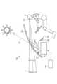
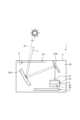
車両用表示装置1は、図1に示すように、例えば自動車等の車両100に搭載されるヘッドアップディスプレイ装置である。車両用表示装置1は、車両100において、インストルメントパネル102の内側にメータ104と共に配置され、ウインドシールド103に表示画像を投影する。車両用表示装置1は、被投影部材であるウインドシールド103に表示画像を投影して、ドライバDのアイポイントEPの前方に虚像Sを表示する。ウインドシールド103は、入射する光の一部を反射し、他の一部を透過させる半透過性を有することから、車両100の前景を透過させながら、車両用表示装置1から投影される表示画像を表示光LとしてドライバDのアイポイントEPに向けて反射する。ウインドシールド103は、車両用表示装置1の外部に設けられており、例えばインストルメントパネル102の上方に配置されている。アイポイントEPは、ドライバDの視点位置として予め想定される。ドライバDは、ウインドシールド103によって反射された表示画像を虚像Sとして認識する。虚像Sは、ドライバDにとって、ウインドシールド103よりも前方に認識される。車両用表示装置1は、車両100内のECU(Electronic Control Unit:電子制御ユニット)105に接続されており、ECU105からの制御信号に応じて駆動する場合がある。ECU105は、例えば、インストルメントパネル102上に配置された照度センサ106に接続されている。車両100は、例えば、当該車両100の周囲の明るさに合わせてヘッドライト(不図示)の点灯/消灯を自動的に行うオートライト機能を有する。ECU105は、例えば、照度センサ106の検出結果により、周囲の照度が1000ルクス未満であると判断するとヘッドライトを点灯し、周囲の照度が7000ルクス以上であると判断するとヘッドライトを消灯する。本実施形態の車両用表示装置1は、図2に示すように、筐体2と、2つの反射ミラー3と、表示器5と、調光部材6と、制御部7とを含んで構成される。[Embodiment]
The
筐体2は、例えば、合成樹脂材料を箱状に成形したものであり、内部に内部空間2bを有する。筐体2は、図2に示すように、内部空間2bに、上述した表示器5、2つの反射ミラー3、及び制御部7を収容し、これらを支持している。筐体2は、車両用表示装置1の外部と内部空間2bとの間を連通する開口2aを有する。開口2aは、筐体2において、ウインドシールド103に対向する位置に設けられる。開口2aは、調光部材6で閉塞されている。本実施形態の車両用表示装置1は、筐体2から調光部材6を介してウインドシールド103に向けて表示光Lを出射する。表示光Lは、表示器5から出射され、反射ミラー3により反射された光である。 The
2つの反射ミラー3は、図2に示すように、表示器5からウインドシールド103までの表示光Lの光路上に配置され、表示器5から出射された表示光Lをウインドシールド103に向けて反射する。本実施形態の2つの反射ミラー3は、平面ミラー8と、凹面ミラー9とで構成される。 The two reflecting
平面ミラー8は、反射面が平面で形成され、表示器5と対向する位置に配置される。平面ミラー8は、表示器5から出射された表示光Lを反射面で凹面ミラー9に向けて全反射させる。 The
凹面ミラー9は、反射面が凹状曲面(または凸状曲面)で形成され、平面ミラー8と対向する位置に配置される。凹面ミラー9は、平面ミラー8で反射した表示光Lを、調光部材6を介してウインドシールド103に向けて全反射させる。本実施形態の凹面ミラー9は、拡大ミラーとしての機能を有する。すなわち、凹面ミラー9は、当該凹面ミラー9にて反射する前の表示光Lが表す表示画像と比較して当該凹面ミラー9にて反射した後の表示光Lが表す表示画像が相対的に大きくなるように当該表示画像を拡大して反射する。ここで外光SLは、調光部材6を介して筐体2内に入射する太陽光である。外光SLは、拡大ミラーとして機能する凹面ミラー9に反射することで集光される。そのため、凹面ミラー9を介して表示器5に向かう外光SLは、集光された光である。 The
表示器5は、ウインドシールド103に投影される表示画像を表示光Lとして出射するものである。表示器5は、液晶表示ユニット21と、バックライトユニット22と、温度センサ23と、光学センサ24とを含んで構成される。 The
液晶表示ユニット21は、いわゆる液晶パネルであり、例えば光透過型または光半透過型のTFT液晶(Thin Film Transistor Liquid Crystal Display)等から成る。液晶表示ユニット21は、裏面側から照明されることで表面側の表示面が発光する。液晶表示ユニット21は、バックライトユニット22から出射された光の光路上に配置され、裏面側から照明されることで表面側の表示面が発光する。液晶表示ユニット21は、平面ミラー8を介して入射する外光SLを透過する機能を有する。液晶表示ユニット21は、例えば、入射した外光SLを屈折させることなく、光学センサ24に向けて透過させる。 The liquid
バックライトユニット22は、液晶表示ユニット21を裏面側から照明するものである。バックライトユニット22は、反射ミラー3のうちの平面ミラー8と対向して配置される。バックライトユニット22は、例えば、車両100内のバッテリー(不図示)から得られる電力により駆動する。 The
温度センサ23は、照射情報取得部の一例であり、表示器5の温度を検出するものであり、例えば、サーミスタや熱電対、測温抵抗体(RTD:RESISTANCE TEMPERATURE DETECTOR)、IC温度センサ等で構成される。温度センサ23は、表示器5の内部空間に配置され、液晶表示ユニット21またはバックライトユニット22の近傍に配置される。温度センサ23は、制御部7に電気的に接続されており、例えば検出値(検出温度)を一定の間隔で制御部7に出力する。照射情報取得部としての温度センサ23は、制御部7に対して照射情報として検出値を出力する。 The
光学センサ24は、照射情報取得部の一例であり、筐体2の外部から調光部材6を透過し、反射ミラー3を介して表示器5に入射する外光SLを検出するものである。光学センサ24は、表示器5に入射する外光SLの光路上で、バックライトユニット22を挟んで液晶表示ユニット21の反対側に配置される。光学センサ24は、例えば、赤外線センサで構成され、外光SLの赤外領域の光(赤外線)を検出する。具体的には、光学センサ24は、外光SLの赤外領域の光(赤外線)を受光して電気信号に変換し、当該電気信号を検出信号として制御部7に出力する。照射情報取得部としての光学センサ24は、外光SLを検出している場合、制御部7に対して照射情報として検出信号を出力し、外光SLを検出しなくなった場合は、制御部7に対して検出信号を出力しない。 The
調光部材6は、表示光Lの光路上に配置され、光の透過率を電気的に可変できるものである。調光部材6は、印加電圧の電圧値を変えると、例えば最小透過率と最大透過率との間で透過率の状態を変更することができる。最小透過率は、例えば0%とすることができるが、任意の値に設定することもできる。透過率が0%の場合、非透過状態である。一方、最大透過率は、例えば100%とすることができるが、任意の値に設定することができる。本実施形態の調光部材6は、制御部7により印加される電圧値に応じて、第1透過率の状態と、第1透過率より小さい第2透過率の状態とに切り替えることができる。第1透過率は、最大透過率であってもよいし、任意の値であってもよい。第2透過率は、最小透過率であってもよいし、任意の値であってもよい。調光部材6は、平板状またはフィルム状に形成されており、例えば、開口2aを閉塞する位置に配置される。なお、調光部材6は、制御部7により印加される電圧値に応じて、第1透過率、第2透過率以外の任意の透過率に切り替えることも可能である。 The
制御部7は、調光制御部の一例であり、図2に示すように、表示器5に電気的に接続され、表示器5の動作を制御する。制御部7は、光学センサ24による外光SLの検出結果、または、温度センサ23による検出値に基づいて、調光部材6における透過率を切り替える。制御部7は、例えばICチップ等で構成され、車両100内のバッテリーから得られる電力により駆動する。制御部7は、車両100内のECU105と電気的に接続され、当該ECU105との間で信号のやりとりを行っている。 The
制御部7は、外光SLが表示器5に照射されているか否かを示す照射情報に基づいて、調光部材6の透過率を切り替える。例えば、制御部7は、照射情報が、表示器5に外光SLが照射されていることを示す場合、調光部材6を第1透過率の状態から第2透過率の状態に切り替える。具体的には、制御部7は、光学センサ24により外光SLが検出された場合、当該光学センサ24から照射情報として検出信号を受信し、調光部材6を第1透過率の状態から第2透過率の状態に切り替える。また、制御部7は、光学センサ24により外光SLが検出された後、外光SLが検出されなくなった場合、光学センサ24から照射情報としての検出信号を受信しなくなることから、調光部材6を第2透過率の状態から第1透過率の状態に切り替える。つまり、制御部7は、調光部材6が第2透過率に切り替わった状態で、光学センサ24から検出信号を受信しなくなった場合、調光部材6を第2透過率の状態から第1透過率の状態に切り替える。 The
また、制御部7は、温度センサ23による検出値が閾値を超えた場合、温度センサ23から照射情報として検出値を受信し、当該検出値と閾値とを比較して検出値が閾値を超えたと判定した場合、調光部材6の透過率を第1透過率の状態から第2透過率の状態に切り替える。閾値は、例えば、液晶表示ユニット21が破損するおそれがある温度(ここでは限界温度とする。)であってもよいし、任意の温度であってもよい。例えば、閾値が50℃、第1透過率が100%の場合、制御部7は、第2透過率である75%に切り替える。また、閾値が75℃、第1透過率が100%の場合、制御部7は、第2透過率である50%に切り替える。また、閾値が100℃以上、第1透過率が100%の場合、制御部7は、第2透過率である0%に切り替える。また、制御部7は、温度センサ23の検出値が閾値を超えた後、温度センサ23により新たに検出された検出値が閾値以下に低下した場合、調光部材6を第2透過率の状態から第1透過率の状態に切り替える。つまり、制御部7は、調光部材6が第2透過率に切り替わった状態で、温度センサ23から照射情報として受信した新たな検出値が閾値以下であると判定した場合、調光部材6を第2透過率の状態から第1透過率の状態に切り替える。 Further, when the detected value by the
次に、車両用表示装置1における虚像表示動作について説明する。まず、表示器5から出射された表示光Lは、平面ミラー8に向かう。平面ミラー8は、表示器5から入射した表示光Lを凹面ミラー9に向けて反射する。凹面ミラー9は、平面ミラー8から入射する表示光Lを、凹状の反射面により、調光部材6を介してウインドシールド103に向けて反射させる。これにより、ウインドシールド103に表示光Lに対応する表示画像が投影され、ドライバDのアイポイントEPの前方に虚像Sが表示される。 Next, the virtual image display operation in the
次に、車両用表示装置1における調光部材6の透過率の状態変化について図3の(A)、図3の(B)を参照して説明する。まず、調光部材6を透過して筐体2の内部空間2bに入射した外光SLは、凹面ミラー9により一部または全部が平面ミラー8に向けて反射する。平面ミラー8は、凹面ミラー9からの外光SLの一部または全部を表示器5に向けて反射する。平面ミラー8から表示器5に向かう外光SLは、液晶表示ユニット21及びバックライトユニット22を透過して光学センサ24に向かう。図3の(A)において、制御部7は、光学センサ24により外光SLが検出されたか否かを判定する(ステップS1)。光学センサ24により外光SLが検出されたと判定した場合、制御部7は、調光部材6を第1透過率の状態から第2透過率の状態に切り替える(ステップS2)。一方、光学センサ24により外光SLが検出されていない場合、ステップS1を繰り返す。 Next, changes in the transmittance of the
次に、制御部7は、ステップS2の後において、光学センサ24により外光SLが検出されなくなったか否かを判定する(ステップS3)。光学センサ24により外光SLが検出されなくなったと判定した場合、制御部7は、調光部材6を第2透過率の状態から第1透過率の状態に切り替えて(ステップS4)、本処理を終了する。なお、ステップS4の後に本処理を終了しているが、ステップS1へ移行してもよい。凹面ミラー9を介して表示器5に向かう外光SLは、当該凹面ミラー9により集光されることから表示器5に照射されると当該表示器5の温度が急上昇する。そこで、調光部材6の透過率が第1透過率から当該第1透過率よりも小さい第2透過率に切り替わることで、反射ミラー3を介して表示器5に照射される外光SLを低減し、外光SLによる表示器5の温度上昇を抑制することができる。 Next, after step S2, the
図3の(B)において、制御部7は、温度センサ23の検出値が閾値を超えたか否かを判定する(ステップS10)。温度センサ23の検出値が閾値を超えたと判定した場合、制御部7は、調光部材6を第1透過率の状態から第2透過率の状態に切り替える(ステップS11)。一方、温度センサ23の検出値が閾値を超えていない場合、ステップS10を繰り返す。次に、制御部7は、調光部材6が第1透過率の状態から第2透過率の状態に切り替えられた後、温度センサ23の検出値が閾値以下となったか否かを判定する(ステップS12)。温度センサ23の検出値が閾値以下となったと判定した場合、制御部7は、調光部材6を第2透過率の状態から第1透過率の状態に切り替えて(ステップS13)、本処理を終了する。なお、ステップS13の後に本処理を終了しているが、ステップS10へ移行してもよい。 In FIG. 3B, the
表示器5は、制御部7による制御に応じて、細分化された複数の表示領域33毎にコンテンツ40を表示するコンテンツ表示状態と、コンテンツ40を表示しないコンテンツ非表示状態とに切り替える。そのため、表示器5により表示される虚像Sでは、図4の(B)、図5の(B)に示すように、連結された複数の表示領域33aには、所望の形状を有するコンテンツ40が表示され、複数の表示領域33bには、コンテンツ40が表示されない。 The
調光部材6は、図4の(A)、図5の(A)に示すように、表示光Lの透過方向から視て、複数の透過領域10に細分化されている場合、透過領域10毎に第1透過率の状態と第2透過率の状態とに切り替えることが可能である。なお、調光部材6は、例えば透過率の変更が可能な調光フィルムを、想定される透過領域の数に応じて複数枚設けることで実現することが可能である。 As shown in FIGS. 4A and 5A, when the
制御部7は、光学センサ24により外光SLが検出されていない場合または温度センサ23の検出値が閾値以下である場合、複数の透過領域10のうち、コンテンツ表示状態の表示領域33aに対応する領域を第1透過率の状態で維持し、かつ、コンテンツ非表示状態の表示領域33bに対応する領域を第2透過率の状態で維持する。一方、制御部7は、光学センサ24により外光SLが検出された場合または温度センサ23の検出値が閾値を超えた場合、複数の透過領域10のうち、コンテンツ表示状態の表示領域33aに対応する領域を第1透過率の状態から第2透過率の状態に切り替え、かつ、コンテンツ非表示状態の表示領域33bに対応する領域を第2透過率の状態で維持する。具体的には、光学センサ24が外光SLを検出した場合または温度センサ23の検出値が閾値を超えた場合、調光部材6は、図4の(A)に示す外光未検出時の状態から図5の(A)に示す外光検出時の状態に変化する。調光部材6は、光学センサ24が外光SLを検出していない場合または温度センサ23の検出値が閾値以下である場合、透過領域10aが第1透過率の状態で維持され、透過領域10bが第2透過率の状態で維持される。一方、光学センサ24が外光SLを検出した場合または温度センサ23の検出値が閾値を超えた場合、虚像Sは、図4の(B)に示す外光未検出時の状態から図5の(B)に示す外光検出時の状態に変化する。虚像Sは、光学センサ24が外光SLを検出していない場合または温度センサ23の検出値が閾値以下である場合、表示領域33aが第1透過率の状態で維持され、表示領域33bが第2透過率の状態で維持される。 When the external light SL is not detected by the
以上説明した車両用表示装置1は、車両100のウインドシールド103に投影される表示画像を表示光Lとして出射する表示器5と、表示光Lの光路上に配置された調光部材6と、照射情報取得部により取得された照射情報に基づいて、調光部材6を第1透過率の状態と第1透過率よりも小さい第2透過率の状態とに切り替える制御部7とを備える。制御部7は、取得された照射情報が、表示器5に外光SLが照射されていることを示す場合、調光部材6を第1透過率の状態から第2透過率の状態に切り替える。例えば、制御部7は、光学センサ24により外光SLが検出された場合、調光部材6を第1透過率の状態から第2透過率の状態に切り替える。また、制御部7は、温度センサ23の検出値が閾値を超えた場合、調光部材6を第1透過率の状態から第2透過率の状態に切り替える。 The
上記構成により、調光部材6の透過率を小さくすることで調光部材6を透過して表示器5に照射される外光SLを低減し、調光部材6が第1透過率の状態にある場合と比較して第2透過率の状態における表示器5の温度上昇を抑制するので、外光SLによる表示器5の温度上昇を抑制することができる。また、従来は、外光SLによる表示器5の温度上昇を抑制するために、表示器5を消灯または反射ミラー3の角度変更を行うと、表示されるべき速度や警告等に関するコンテンツ40が一時的に表示されない場合があるが、必要なコンテンツ40の表示を継続させつつ表示器5の温度上昇を抑制することが可能となる。また、反射ミラー3の角度変更を行うためにモータ等で駆動すると駆動音が生じてドライバDが煩わしさを感じる可能性があるが、ドライバDが駆動音を聞くことなく、表示器5の温度上昇を抑制することが可能となる。さらに、従来と比較して反射ミラー3の角度変更に必要なスペースが不要となり、装置の小型化を図ることができる。また、第2透過率を非透過状態にする設定することで、虚像Sを一時的に非表示にすることもでき、従来であったパークポジションの代わりとすることができる。 With the above configuration, by reducing the transmittance of the
また、車両用表示装置1では、制御部7は、調光部材6が第2透過率に切り替わった状態で、光学センサ24により外光SLが検出されなくなったとき、調光部材6を第2透過率の状態から第1透過率の状態に切り替える。または、制御部7は、調光部材6が第2透過率に切り替わった状態で、温度センサ23により新たに検出された検出値が閾値以下に低下したときは、調光部材6を第2透過率の状態から第1透過率の状態に切り替える。このように、外光SLの照射状態、及び、表示器5の温度状態に合わせて調光部材6の透過率を切り替えることで、表示器の温度上昇が収まったときには、調光部材6の透過率を大きくして、虚像Sの視認性の低下を抑制することができる。 Further, in the
また、車両用表示装置1では、制御部7は、照射情報が、表示器5に外光SLが照射されていないを示す場合、複数の透過領域10のうち、コンテンツ表示状態の表示領域33aに対応する領域を第1透過率の状態で維持し、かつ、コンテンツ非表示状態の表示領域33bに対応する領域を第2透過率の状態で維持する。一方、照射情報が、表示器5に外光SLが照射されていることを示す場合、複数の透過領域10のうち、コンテンツ表示状態の表示領域33aに対応する領域を第1透過率の状態から第2透過率の状態に切り替え、かつ、コンテンツ非表示状態の表示領域33bに対応する領域を第2透過率の状態で維持する。これにより、必要なコンテンツ40の表示を維持しつつ、外光SLによる表示器5の温度上昇を抑制できるため、表示器5の消灯や減光が不要となり、虚像Sの視認性を向上させることができる。 In addition, in the
(変形例)
実施形態の第1変形例に係る表示器5は、複数の表示領域33で構成され、少なくとも一部がコンテンツ表示状態を常時維持するコンテンツ常時表示領域群32と、コンテンツ常時表示領域群32以外の表示領域33で構成され、少なくとも一部がコンテンツ表示状態を一時的に維持するコンテンツ一時表示領域群31とを有する。コンテンツ一時表示領域群31における表示領域33aに表示されるコンテンツ40は、例えば車両100の進行方向を案内するアイコンや横断歩道があることを示すアイコン等が含まれる。一方、コンテンツ常時表示領域群32における表示領域33aに表示されるコンテンツ40は、例えば車両100の速度を示す情報や警告を示す情報等が含まれる。(Modification)
The
制御部7は、光学センサ24により外光SLが検出されていない場合または温度センサ23の検出値が閾値以下である場合、複数の透過領域10のうち、コンテンツ常時表示領域群32におけるコンテンツ表示状態の表示領域33aに対応する領域を第1透過率の状態で維持し、かつ、コンテンツ常時表示領域群32におけるコンテンツ非表示状態の表示領域33bに対応する領域を第2透過率の状態で維持する。一方、制御部7は、光学センサ24により外光SLが検出された場合または温度センサ23の検出値が閾値を超えた場合、複数の透過領域10のうち、コンテンツ一時表示領域群31におけるコンテンツ表示状態の表示領域33aに対応する領域を第1透過率の状態から第2透過率の状態に切り替え、かつ、コンテンツ一時表示領域群31におけるコンテンツ非表示状態の表示領域33bに対応する領域を第2透過率の状態で維持する。具体的には、光学センサ24が外光SLを検出した場合または温度センサ23の検出値が閾値を超えた場合、調光部材6は、図6の(A)に示す外光未検出時の状態から図7の(A)に示す外光検出時の状態に変化する。調光部材6は、光学センサ24が外光SLを検出していない場合または温度センサ23の検出値が閾値以下である場合、透過領域10aが第1透過率の状態で維持され、透過領域10bが第2透過率の状態で維持される。一方、光学センサ24が外光SLを検出した場合または温度センサ23の検出値が閾値を超えた場合、虚像Sは、図6の(B)に示す外光未検出時の状態から図7の(B)に示す外光検出時の状態に変化する。虚像Sは、光学センサ24が外光SLを検出していない場合または温度センサ23の検出値が閾値以下である場合、表示領域33aが第1透過率の状態で維持され、表示領域33bが第2透過率の状態で維持される。 When the
また、第1変形例に係る車両用表示装置1では、表示器5は、複数の表示領域33で構成され、少なくとも一部がコンテンツ表示状態を常時維持するコンテンツ常時表示領域群32と、コンテンツ常時表示領域群32以外の表示領域33で構成され、少なくとも一部がコンテンツ表示状態を一時的に維持するコンテンツ一時表示領域群31とを有する。調光部材6は、細分化された複数の透過領域10毎に第1透過率の状態と第2透過率の状態とに切り替えが可能である。制御部7は、照射情報が、表示器5に外光SLが照射されていないを示す場合、複数の透過領域10のうち、コンテンツ常時表示領域群32におけるコンテンツ表示状態の表示領域33aに対応する領域を第1透過率の状態で維持し、かつ、コンテンツ常時表示領域群32におけるコンテンツ非表示状態の表示領域33bに対応する領域を第2透過率の状態で維持する。制御部7は、照射情報が、表示器5に外光SLが照射されていることを示す場合、複数の透過領域10のうち、コンテンツ一時表示領域群31におけるコンテンツ表示状態の表示領域33aに対応する領域を第1透過率の状態から第2透過率の状態に切り替え、かつ、コンテンツ一時表示領域群31におけるコンテンツ非表示状態の表示領域33bに対応する領域を第2透過率の状態で維持する。 Further, in the
上記構成により、第1透過率の状態が維持されるコンテンツ常時表示領域群32の表示領域33aは、コンテンツ40が表示された状態において、第1透過率から第2透過率の状態に切り替わった場合と比較して、コンテンツ40の視認性を維持することができる。一方、第1透過率の状態から第2透過率の状態に切り替わるコンテンツ一時表示領域群31の表示領域33aは、第1透過率の状態が維持された場合と比較して、表示器5の温度上昇を抑制することができる。従って、コンテンツ40の視認性を維持しつつ、表示器5の温度上昇を抑制することができる。また、表示領域33aと表示領域33bとで調光部材6の透過率の状態が異なるので、領域間のコントラストが明確になる。また、調光部材6が、細分化された複数の透過領域10毎に第1透過率の状態と第2透過率の状態とに切り替えが可能であれば、コンテンツ40の表示状態の変化に追従して透過率の状態を迅速に切り替えることができる。 With the above configuration, the
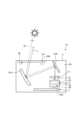
図8は、実施形態の第2変形例に係る車両用表示装置の概略構成を示す模式図である。変形例に係る車両用表示装置1Aは、図8に示すように、調光部材6の配置位置が上記車両用表示装置1と異なる。 FIG. 8 is a schematic diagram showing a schematic configuration of a vehicle display device according to a second modification of the embodiment. As shown in FIG. 8, the
車両用表示装置1Aでは、調光部材6は、表示光Lの光路上にあって、反射ミラー3と表示器5の間に配置されている。開口2aは、表示光Lを透過させる透明カバー50で閉塞されている。透明カバー50は、開口2aを閉塞することで、外部から筐体2内へのホコリ等の侵入を防止する。調光部材6は、図示のように、表示器5と離間して配置してもよいし、表示器5に接触させて配置してもよい。これにより、調光部材6の厚み方向と直行する平面方向のサイズを小さくすることができる。また、調光部材6の各透過領域のサイズと表示器5の表示画面のサイズが略同一にできることから、調光部材6を開口2aに配置する場合に比べて、コンテンツの表示位置の設計が容易になる。 In the
また、上記実施形態の他の変形例として、GPS(Global Positioning System)衛星から受信した位置情報や方位情報に基づいて太陽の位置を推定し、推定した太陽の位置に基づいて外光SLの照射による表示器5の温度上昇等を推定する構成であってもよい。例えば、ECU105は、照射情報取得部の一例として機能し、GPS衛星からの位置情報等を照射情報として取得する。制御部7は、ECU105により取得された照射情報に基づいて調光部材6の透過率を切り替えるものとする。なお、上記他の変形例の場合、ECU105が、照射情報取得部の一例として機能しているが、これに限定されず、制御部7が照射情報取得部の一例として機能してもよい。 Further, as another modified example of the above embodiment, the position of the sun is estimated based on position information and direction information received from GPS (Global Positioning System) satellites, and the irradiation of external light SL is performed based on the estimated position of the sun. It may be configured to estimate the temperature rise of the
なお、上記実施形態及び変形例では、表示器5は、液晶方式であるが、他の方式、例えばレーザ方式やDLP(Digital Light Processing)方式、プロジェクタ方式であってもよい。 In addition, although the
また、上記実施形態及び変形例では、温度センサ23は、表示器5の内部に配置されているが、これに限定されず、筐体2の内部空間2bにあって表示器5の外部に配置されていてもよい。例えば、図8に示すように、温度センサ23Aは、制御部7を構成する基板上に配置されてもよい。また、温度センサ23は、複数の位置にそれぞれ配置されていてもよい。例えば、温度センサ23が表示器5の内部に配置され、温度センサ23Aが筐体2の内部空間2bにあって表示器5の外部に配置される構成であってもよい。 Further, in the above-described embodiment and modification, the
また、上記実施形態及び変形例では、温度センサ23は、検出値を制御部7に直接出力しているが、これに限定されるものではない。例えば、温度センサ23は、検出値をメータ104または車両100内のECU105を介して制御部7に出力する構成であってもよい。 In addition, in the above-described embodiment and modification, the
また、上記実施形態及び変形例では、光学センサ24は、表示器5の内部に配置されているが、これに限定されず、筐体2の内部空間2bにあって表示器5の外部に配置されていてもよい。例えば、図8に示すように、光学センサ24Aは、透明カバー50の周辺であって外光SLを検出可能な位置に配置されていてもよい。また、光学センサ24は、複数の位置にそれぞれ配置されていてもよい。例えば、光学センサ24が表示器5の内部に配置され、光学センサ24Aが筐体2の内部空間2bにあって表示器5の外部に配置される構成であってもよい。 In addition, in the above-described embodiment and modification, the
また、上記実施形態及び変形例では、光学センサ24は、赤外線センサであるが、外光SLを検出できるものであれば、例えば、照度センサであってもよい。光学センサ24が照度センサである場合、光学センサ24は、外光SLの可視領域の光(可視光線)を受光して電気信号に変換し、当該電気信号を制御部7に出力する。また、光学センサ24は、赤外線センサ及び照度センサのいずれか一方が配置されていてもよいし、赤外線センサ及び照度センサの両方が配置されていてもよい。 Further, in the above-described embodiment and modification, the
また、上記実施形態及び変形例では、調光部材6は、開口2aを閉塞する位置に配置されていたり、表示光Lの光路上にあって、反射ミラー3と表示器5の間に配置されているが、これに限定されるものではない。平面ミラー8に適用してもよい。この場合、透過率ではなく反射率を切り替える。 Further, in the above-described embodiment and modified example, the
また、上記実施形態及び変形例では、照射情報取得部として、車両用表示装置1の内部に配置された温度センサ23,23A、光学センサ24,24Aについて説明したが、これらに限定されるものではない。例えば、照射情報取得部が車両100に搭載された照度センサ106であってもよい。この場合、照度センサ106による検出信号をECU105を介して制御部7が受信し、当該検出信号(照射情報)に基づいて制御部7が調光部材6の透過率を切り替える構成となる。例えば、照射情報取得部が車両100に搭載された室温センサ(不図示)であってもよい。この場合、室温センサによる検出値をECU105を介して制御部7が受信し、当該検出値(照射情報)に基づいて制御部7が調光部材6の透過率を切り替える構成となる。なお、照射情報取得部として、車両用表示装置1の内部に配置された温度センサ23,23Aと、車両100に搭載された照度センサ106とを組み合わせてもよいし、車両100に搭載された室温センサと、車両用表示装置1の内部に配置された光学センサ24,24Aとを組み合わせてもよい。また、車両100に搭載された室温センサと、車両100に搭載された照度センサ106とを組み合わせてもよい。 Further, in the above-described embodiment and modified example, the
また、上記実施形態及び変形例に係る車両用表示装置1,1Aでは、制御部7は、照射情報が、表示器5に外光SLが照射されていることを示す場合か、そうでない場合かにより切り替えを行っているが、照射情報を受信したか否かで切り替えを行うように構成してもよい。 Further, in the
また、上記実施形態及び変形例に係る車両用表示装置1,1Aでは、温度センサ23及び光学センサ24の両方を備えているが、いずれか一方であってもよい。また、制御部7は、光学センサ24の検出結果を優先して切り替えを行うように構成されていてもよい。 Moreover, although the
また、上記実施形態及び変形例では、車両用表示装置1,1Aは、2つの反射ミラー3を有しているが、これに限定されず、1つの反射ミラー3を有していてもよいし、3つ以上の反射ミラー3を有していてもよい。平面ミラー8は、凹面ミラーであってもよいし、例えば、凸面ミラー、非球面ミラー、球面ミラー、自由曲面ミラー等であってもよい。凹面ミラー9は、例えば、凸面ミラー、非球面ミラー、球面ミラー、自由曲面ミラー等であってもよい。また、凹面ミラー9は、拡大ミラーとしての機能を有するが、これに限定されず、補正ミラーとしての機能を有してもよい。 In addition, in the above-described embodiment and modified example, the
また、上記実施形態及び変形例では、車両用表示装置1,1Aは、表示画像を車両100のウインドシールド103に投影しているが、これに限定されず、例えばコンバイナ等に投影してもよい。 In addition, in the above-described embodiments and modifications, the
また、上記実施形態及び変形例では、車両用表示装置1,1Aは、自動車等の車両100に適用されているが、これに限定されず、例えば車両100以外の船舶や航空機等に適用してもよい。 Further, in the above embodiments and modifications, the
1,1A 車両用表示装置
2 筐体
2a 開口
2b 内部空間
3 反射ミラー
5 表示器
6 調光部材
7 制御部
10,10a,10b 透過領域
23 温度センサ
24 光学センサ
31 コンテンツ一時表示領域群
32 コンテンツ常時表示領域群
33,33a,33b 表示領域
40 コンテンツ
100 車両
103 ウインドシールド
L 表示光
S 虚像
SL 外光
Claims (4)
Translated fromJapanese前記表示器から前記被投影部材までの前記表示光の光路上に少なくとも1つ配置され、前記表示光を反射する反射ミラーと、
太陽光を含む外光が前記表示器に照射されているか否かを示す照射情報として取得する照射情報取得部と、
前記表示光の光路上に配置された調光部材と、
前記照射情報取得部により取得された前記照射情報に基づいて、前記調光部材の透過率を切り替える調光制御部と、を備え、
前記調光制御部は、
前記照射情報が、前記表示器に前記外光が照射されていることを示す場合、前記調光部材を第1透過率の状態から前記第1透過率よりも小さい第2透過率の状態に切り替え、
前記表示器は、
細分化された複数の表示領域毎にコンテンツを表示するコンテンツ表示状態と、前記コンテンツを表示しないコンテンツ非表示状態とに切り替え、
前記調光部材は、
細分化された複数の透過領域毎に前記第1透過率の状態と前記第2透過率の状態とに切り替えが可能であり、
前記調光制御部は、
前記照射情報が、前記表示器に前記外光が照射されていないことを示す場合、複数の前記透過領域のうち、前記コンテンツ表示状態の前記表示領域に対応する領域を前記第1透過率の状態で維持し、かつ、前記コンテンツ非表示状態の前記表示領域に対応する領域を前記第2透過率の状態で維持し、
前記照射情報が、前記表示器に前記外光が照射されていることを示す場合、複数の前記透過領域のうち、前記コンテンツ表示状態の前記表示領域に対応する領域を前記第1透過率の状態から前記第2透過率の状態に切り替え、かつ、前記コンテンツ非表示状態の前記表示領域に対応する領域を前記第2透過率の状態で維持する、
ことを特徴とする車両用表示装置。a display device that emits a display image projected onto a projection target member provided outside the vehicle display device as display light;
at least one reflecting mirror arranged on an optical path of the display light from the display device to the projection target member and reflecting the display light;
an irradiation information acquisition unit that acquires irradiation information indicating whether the display is irradiated with external light including sunlight;
a light control member arranged on the optical path of the display light;
a light control control unit that switches the transmittance of the light control member based on the irradiation information acquired by the irradiation information acquisition unit;
The dimming control unit
When the irradiation information indicates that the display is irradiated with the external light, the light control member is switched from a state of a first transmittance to a state of a second transmittance smaller than the first transmittance.picture,
The indicator is
switching between a content display state in which content is displayed in each of a plurality of subdivided display areas and a content non-display state in which the content is not displayed;
The light control member is
It is possible to switch between the state of the first transmittance and the state of the second transmittance for each of the plurality of subdivided transmission areas,
The dimming control unit
When the irradiation information indicates that the display is not irradiated with the external light, the region corresponding to the display region in the content display state, among the plurality of transmission regions, is in the state of the first transmittance. and maintaining an area corresponding to the display area in the content non-display state in the state of the second transmittance,
When the irradiation information indicates that the display is irradiated with the external light, the region corresponding to the display region in the content display state, among the plurality of transmission regions, is in the state of the first transmittance. to the state of the second transmittance, and maintaining an area corresponding to the display area in the content non-display state in the state of the second transmittance;
A vehicle display device characterized by:
前記表示器から前記被投影部材までの前記表示光の光路上に少なくとも1つ配置され、前記表示光を反射する反射ミラーと、 at least one reflecting mirror arranged on an optical path of the display light from the display device to the projection target member and reflecting the display light;
太陽光を含む外光が前記表示器に照射されているか否かを示す照射情報として取得する照射情報取得部と、 an irradiation information acquisition unit that acquires irradiation information indicating whether the display is irradiated with external light including sunlight;
前記表示光の光路上に配置された調光部材と、 a light control member arranged on the optical path of the display light;
前記照射情報取得部により取得された前記照射情報に基づいて、前記調光部材の透過率を切り替える調光制御部と、を備え、 a light control control unit that switches the transmittance of the light control member based on the irradiation information acquired by the irradiation information acquisition unit;
前記調光制御部は、 The dimming control unit
前記照射情報が、前記表示器に前記外光が照射されていることを示す場合、前記調光部材を第1透過率の状態から前記第1透過率よりも小さい第2透過率の状態に切り替え、 When the irradiation information indicates that the display is irradiated with the external light, the light control member is switched from a state of a first transmittance to a state of a second transmittance smaller than the first transmittance. ,
前記表示器は、The indicator is
細分化された複数の表示領域毎にコンテンツを表示するコンテンツ表示状態と、前記コンテンツを表示しないコンテンツ非表示状態とに切り替え、 switching between a content display state in which content is displayed in each of a plurality of subdivided display areas and a content non-display state in which the content is not displayed;
複数の前記表示領域で構成され、少なくとも一部が前記コンテンツ表示状態を常時維持するコンテンツ常時表示領域群と、前記コンテンツ常時表示領域群以外の表示領域で構成され、少なくとも一部が前記コンテンツ表示状態を一時的に維持するコンテンツ一時表示領域群と、を有し、 A content constant display area group, at least a part of which always maintains the content display state, and a display area other than the content constant display area group, at least a part of which is in the content display state. and a content temporary display area group that temporarily maintains
前記調光部材は、 The light control member is
細分化された複数の透過領域毎に前記第1透過率の状態と前記第2透過率の状態とに切り替えが可能であり、 It is possible to switch between the state of the first transmittance and the state of the second transmittance for each of the plurality of subdivided transmission areas,
前記調光制御部は、 The dimming control unit
前記照射情報が、前記表示器に前記外光が照射されていないことを示す場合、複数の前記透過領域のうち、前記コンテンツ常時表示領域群における前記コンテンツ表示状態の前記表示領域に対応する領域を前記第1透過率の状態で維持し、かつ、前記コンテンツ常時表示領域群における前記コンテンツ非表示状態の前記表示領域に対応する領域を前記第2透過率の状態で維持し、 When the irradiation information indicates that the display is not irradiated with the external light, among the plurality of transmissive regions, the region corresponding to the display region in the content display state in the content constant display region group is selected. maintaining the first transmittance state, and maintaining an area corresponding to the display area in the content non-display state in the content always-display area group at the second transmittance state;
前記照射情報が、前記表示器に前記外光が照射されていることを示す場合、複数の前記透過領域のうち、前記コンテンツ一時表示領域群における前記コンテンツ表示状態の前記表示領域に対応する領域を前記第1透過率の状態から前記第2透過率の状態に切り替え、かつ、前記コンテンツ一時表示領域群における前記コンテンツ非表示状態の前記表示領域に対応する領域を前記第2透過率の状態で維持する、 When the irradiation information indicates that the display is irradiated with the external light, a region corresponding to the display region in the content display state in the content temporary display region group among the plurality of transmissive regions is selected. Switching from the state of the first transmittance to the state of the second transmittance, and maintaining an area corresponding to the display area in the content non-display state in the content temporary display area group in the state of the second transmittance. do,
ことを特徴とする車両用表示装置。A vehicle display device characterized by:
前記調光制御部は、
前記光学センサにより前記外光が検出された場合、前記調光部材を前記第1透過率の状態から前記第2透過率の状態に切り替え、
前記光学センサにより前記外光が検出された後、前記外光を検出しなくなったときは、前記調光部材を前記第2透過率の状態から前記第1透過率の状態に切り替える、
請求項1または2に記載の車両用表示装置。The irradiation information acquisition unit is an optical sensor that is arranged inside or outside the display and detects incident external light,
The dimming control unit
when the external light is detected by the optical sensor, switching the light control member from the state of the first transmittance to the state of the second transmittance;
After the external light is detected by the optical sensor, when the external light is no longer detected, the light control member is switched from the state of the second transmittance to the state of the first transmittance;
The vehicle display device according to claim 1or 2 .
前記調光制御部は、
前記温度センサの検出値が閾値を超えた場合、前記調光部材を前記第1透過率の状態から前記第2透過率の状態に切り替え、
前記温度センサの検出値が前記閾値を超えた後、前記温度センサにより新たに検出された検出値が前記閾値以下に低下した場合、前記調光部材を前記第2透過率の状態から前記第1透過率の状態に切り替える、
請求項1または2に記載の車両用表示装置。The irradiation information acquisition unit is a temperature sensor that is arranged inside or outside the display and detects the temperature of the display,
The dimming control unit
switching the light control member from the state of the first transmittance to the state of the second transmittance when the detected value of the temperature sensor exceeds a threshold;
After the detected value of the temperature sensor exceeds the threshold value, when the detected value newly detected by the temperature sensor falls below the threshold value, the light control member is changed from the second transmittance state to the first transmittance state. switch to transparency state,
The vehicle display device according to claim 1or 2 .
Priority Applications (4)
| Application Number | Priority Date | Filing Date | Title |
|---|---|---|---|
| JP2021036796AJP7268073B2 (en) | 2021-03-09 | 2021-03-09 | vehicle display |
| DE102022104732.6ADE102022104732B4 (en) | 2021-03-09 | 2022-02-28 | vehicle display device |
| CN202210216609.7ACN115047622B (en) | 2021-03-09 | 2022-03-07 | Vehicle display device |
| US17/688,785US11714279B2 (en) | 2021-03-09 | 2022-03-07 | Vehicle display device |
Applications Claiming Priority (1)
| Application Number | Priority Date | Filing Date | Title |
|---|---|---|---|
| JP2021036796AJP7268073B2 (en) | 2021-03-09 | 2021-03-09 | vehicle display |
Publications (2)
| Publication Number | Publication Date |
|---|---|
| JP2022137325A JP2022137325A (en) | 2022-09-22 |
| JP7268073B2true JP7268073B2 (en) | 2023-05-02 |
Family
ID=83005379
Family Applications (1)
| Application Number | Title | Priority Date | Filing Date |
|---|---|---|---|
| JP2021036796AActiveJP7268073B2 (en) | 2021-03-09 | 2021-03-09 | vehicle display |
Country Status (4)
| Country | Link |
|---|---|
| US (1) | US11714279B2 (en) |
| JP (1) | JP7268073B2 (en) |
| CN (1) | CN115047622B (en) |
| DE (1) | DE102022104732B4 (en) |
Families Citing this family (5)
| Publication number | Priority date | Publication date | Assignee | Title |
|---|---|---|---|---|
| JP7534181B2 (en)* | 2020-10-13 | 2024-08-14 | 株式会社Subaru | Vehicle display device |
| JP7693737B2 (en)* | 2023-03-28 | 2025-06-17 | 矢崎総業株式会社 | Image display device |
| JP7693738B2 (en) | 2023-03-28 | 2025-06-17 | 矢崎総業株式会社 | Vehicle display device |
| WO2025047757A1 (en)* | 2023-08-31 | 2025-03-06 | 京セラ株式会社 | Virtual image display device, virtual image display method, and program |
| CN119872232A (en)* | 2025-03-25 | 2025-04-25 | 江苏泽景汽车电子股份有限公司 | Projection assembly, projection equipment and head-up display equipment |
Citations (11)
| Publication number | Priority date | Publication date | Assignee | Title |
|---|---|---|---|---|
| JP2008164908A (en) | 2006-12-28 | 2008-07-17 | Kanto Auto Works Ltd | Head-up display device |
| JP2013228442A (en) | 2012-04-24 | 2013-11-07 | Nippon Seiki Co Ltd | Head-up display device |
| US20140132852A1 (en) | 2011-06-22 | 2014-05-15 | Wolfgang-Peter Pawusch | Display Device Having A Liquid Crystal Display And Method For Protecting A Liquid Crystal Display |
| JP2015152746A (en) | 2014-02-14 | 2015-08-24 | 日本精機株式会社 | display device |
| JP2018106193A (en) | 2018-02-26 | 2018-07-05 | 日本精機株式会社 | Head-up display device |
| JP2019139157A (en) | 2018-02-14 | 2019-08-22 | 株式会社デンソー | Head-up display device |
| JP2020024322A (en) | 2018-08-08 | 2020-02-13 | 京セラ株式会社 | Three-dimensional display device, three-dimensional display system, head-up display system, and moving body |
| JP2020052070A (en) | 2018-09-21 | 2020-04-02 | マクセル株式会社 | Head-up display device |
| DE102018126476A1 (en) | 2018-10-24 | 2020-04-30 | Valeo Schalter Und Sensoren Gmbh | Head-Up Display |
| JP2021026097A (en) | 2019-08-02 | 2021-02-22 | 株式会社ジャパンディスプレイ | Display system and display |
| JP2021085989A (en) | 2019-11-27 | 2021-06-03 | 京セラ株式会社 | Head-up display system and movable body |
Family Cites Families (8)
| Publication number | Priority date | Publication date | Assignee | Title |
|---|---|---|---|---|
| JPS6320243A (en)* | 1986-07-11 | 1988-01-27 | Toyota Motor Corp | Head-up display device for vehicle |
| JPH08175225A (en)* | 1994-12-27 | 1996-07-09 | Mitsubishi Motors Corp | Vehicle display |
| JPH0943531A (en)* | 1995-07-31 | 1997-02-14 | Fujitsu Ltd | Display device for vehicles |
| WO2018168595A1 (en)* | 2017-03-15 | 2018-09-20 | 日本精機株式会社 | Head-up display device |
| DE102019212537A1 (en) | 2018-08-29 | 2020-03-05 | Shadevision GmbH | Three-cell liquid crystal display and adaptive disc element |
| CN113573935A (en)* | 2019-03-19 | 2021-10-29 | 株式会社小糸制作所 | Head-up display for vehicle and head-up display system for vehicle |
| KR20210143474A (en) | 2020-05-20 | 2021-11-29 | 현대모비스 주식회사 | Head up display apparatus having external light blocking function |
| JP2022071763A (en)* | 2020-10-28 | 2022-05-16 | 株式会社ジャパンディスプレイ | Display system |
- 2021
- 2021-03-09JPJP2021036796Apatent/JP7268073B2/enactiveActive
- 2022
- 2022-02-28DEDE102022104732.6Apatent/DE102022104732B4/enactiveActive
- 2022-03-07CNCN202210216609.7Apatent/CN115047622B/enactiveActive
- 2022-03-07USUS17/688,785patent/US11714279B2/enactiveActive
Patent Citations (11)
| Publication number | Priority date | Publication date | Assignee | Title |
|---|---|---|---|---|
| JP2008164908A (en) | 2006-12-28 | 2008-07-17 | Kanto Auto Works Ltd | Head-up display device |
| US20140132852A1 (en) | 2011-06-22 | 2014-05-15 | Wolfgang-Peter Pawusch | Display Device Having A Liquid Crystal Display And Method For Protecting A Liquid Crystal Display |
| JP2013228442A (en) | 2012-04-24 | 2013-11-07 | Nippon Seiki Co Ltd | Head-up display device |
| JP2015152746A (en) | 2014-02-14 | 2015-08-24 | 日本精機株式会社 | display device |
| JP2019139157A (en) | 2018-02-14 | 2019-08-22 | 株式会社デンソー | Head-up display device |
| JP2018106193A (en) | 2018-02-26 | 2018-07-05 | 日本精機株式会社 | Head-up display device |
| JP2020024322A (en) | 2018-08-08 | 2020-02-13 | 京セラ株式会社 | Three-dimensional display device, three-dimensional display system, head-up display system, and moving body |
| JP2020052070A (en) | 2018-09-21 | 2020-04-02 | マクセル株式会社 | Head-up display device |
| DE102018126476A1 (en) | 2018-10-24 | 2020-04-30 | Valeo Schalter Und Sensoren Gmbh | Head-Up Display |
| JP2021026097A (en) | 2019-08-02 | 2021-02-22 | 株式会社ジャパンディスプレイ | Display system and display |
| JP2021085989A (en) | 2019-11-27 | 2021-06-03 | 京セラ株式会社 | Head-up display system and movable body |
Also Published As
| Publication number | Publication date |
|---|---|
| CN115047622B (en) | 2024-06-07 |
| CN115047622A (en) | 2022-09-13 |
| US20220291505A1 (en) | 2022-09-15 |
| JP2022137325A (en) | 2022-09-22 |
| US11714279B2 (en) | 2023-08-01 |
| DE102022104732B4 (en) | 2025-01-16 |
| DE102022104732A1 (en) | 2022-09-15 |
Similar Documents
| Publication | Publication Date | Title |
|---|---|---|
| JP7268073B2 (en) | vehicle display | |
| CN110471182B (en) | Display device for vehicle | |
| CN110471181B (en) | Display device for vehicle | |
| JP7117066B2 (en) | Vehicle information display device and vehicle information display system | |
| US5510983A (en) | On-vehicle display | |
| CN110753875A (en) | Information display device | |
| US20150123878A1 (en) | Information display device | |
| US11376964B2 (en) | Vehicle display device including passage extending through optical member | |
| JP2014069703A (en) | Vehicular display device | |
| US11561394B2 (en) | Information display apparatus and reflecting mirror used therein | |
| CN113741031A (en) | Vehicle-mounted display device | |
| EP3705333A1 (en) | Vehicle display device | |
| JP2007186017A (en) | Display unit for vehicle | |
| JP2009056932A (en) | Rear view mirror for vehicle | |
| JP2002234360A (en) | Vehicle display device and display method thereof | |
| JP2007186016A (en) | Head-up display device for vehicle | |
| JP6593393B2 (en) | Virtual image display device | |
| JP2020067650A (en) | Vehicle display | |
| JP6942747B2 (en) | Vehicle display device | |
| JPH1123997A (en) | On-vehicle headup display | |
| CN116224595B (en) | Head-up display system and vehicle | |
| JPH0518948U (en) | Vehicle display | |
| JP2022135583A (en) | Head-up display for vehicle | |
| KR19980014603A (en) | Apparatus and method for preventing phase distortion in HUD optical systems | |
| KR20190008747A (en) | Head up display |
Legal Events
| Date | Code | Title | Description |
|---|---|---|---|
| A621 | Written request for application examination | Free format text:JAPANESE INTERMEDIATE CODE: A621 Effective date:20220711 | |
| A977 | Report on retrieval | Free format text:JAPANESE INTERMEDIATE CODE: A971007 Effective date:20230228 | |
| A131 | Notification of reasons for refusal | Free format text:JAPANESE INTERMEDIATE CODE: A131 Effective date:20230307 | |
| A521 | Request for written amendment filed | Free format text:JAPANESE INTERMEDIATE CODE: A523 Effective date:20230411 | |
| TRDD | Decision of grant or rejection written | ||
| A01 | Written decision to grant a patent or to grant a registration (utility model) | Free format text:JAPANESE INTERMEDIATE CODE: A01 Effective date:20230418 | |
| A61 | First payment of annual fees (during grant procedure) | Free format text:JAPANESE INTERMEDIATE CODE: A61 Effective date:20230420 | |
| R150 | Certificate of patent or registration of utility model | Ref document number:7268073 Country of ref document:JP Free format text:JAPANESE INTERMEDIATE CODE: R150 |