JP7267920B2 - Substrate separation method - Google Patents
Substrate separation methodDownload PDFInfo
- Publication number
- JP7267920B2 JP7267920B2JP2019536054AJP2019536054AJP7267920B2JP 7267920 B2JP7267920 B2JP 7267920B2JP 2019536054 AJP2019536054 AJP 2019536054AJP 2019536054 AJP2019536054 AJP 2019536054AJP 7267920 B2JP7267920 B2JP 7267920B2
- Authority
- JP
- Japan
- Prior art keywords
- stress
- substrate
- workpiece
- range
- separation
- Prior art date
- Legal status (The legal status is an assumption and is not a legal conclusion. Google has not performed a legal analysis and makes no representation as to the accuracy of the status listed.)
- Active
Links
- 239000000758substrateSubstances0.000titleclaimsdescription130
- 238000000926separation methodMethods0.000titleclaimsdescription118
- 230000035882stressEffects0.000claimsdescription156
- 239000011521glassSubstances0.000claimsdescription86
- 230000003902lesionEffects0.000claimsdescription76
- 239000000463materialSubstances0.000claimsdescription70
- 238000000034methodMethods0.000claimsdescription57
- 230000001419dependent effectEffects0.000claimsdescription18
- 239000002241glass-ceramicSubstances0.000claimsdescription14
- XUIMIQQOPSSXEZ-UHFFFAOYSA-NSiliconChemical compound[Si]XUIMIQQOPSSXEZ-UHFFFAOYSA-N0.000claimsdescription13
- 230000009477glass transitionEffects0.000claimsdescription13
- 239000010703siliconSubstances0.000claimsdescription13
- 229910052710siliconInorganic materials0.000claimsdescription13
- 230000008646thermal stressEffects0.000claimsdescription13
- 238000000576coating methodMethods0.000claimsdescription8
- 239000011248coating agentSubstances0.000claimsdescription7
- 238000004458analytical methodMethods0.000claimsdescription4
- 230000035515penetrationEffects0.000claimsdescription4
- 108090000623proteins and genesProteins0.000claimsdescription4
- 102000004169proteins and genesHuman genes0.000claimsdescription4
- 239000000203mixtureSubstances0.000description61
- GOLCXWYRSKYTSP-UHFFFAOYSA-NArsenious AcidChemical compoundO1[As]2O[As]1O2GOLCXWYRSKYTSP-UHFFFAOYSA-N0.000description30
- QPLDLSVMHZLSFG-UHFFFAOYSA-NCopper oxideChemical compound[Cu]=OQPLDLSVMHZLSFG-UHFFFAOYSA-N0.000description30
- GWEVSGVZZGPLCZ-UHFFFAOYSA-NTitan oxideChemical compoundO=[Ti]=OGWEVSGVZZGPLCZ-UHFFFAOYSA-N0.000description30
- CETPSERCERDGAM-UHFFFAOYSA-Nceric oxideChemical compoundO=[Ce]=OCETPSERCERDGAM-UHFFFAOYSA-N0.000description30
- 229910000422cerium(IV) oxideInorganic materials0.000description30
- QDOXWKRWXJOMAK-UHFFFAOYSA-Ndichromium trioxideChemical compoundO=[Cr]O[Cr]=OQDOXWKRWXJOMAK-UHFFFAOYSA-N0.000description30
- GNTDGMZSJNCJKK-UHFFFAOYSA-Ndivanadium pentaoxideChemical compoundO=[V](=O)O[V](=O)=OGNTDGMZSJNCJKK-UHFFFAOYSA-N0.000description30
- NUJOXMJBOLGQSY-UHFFFAOYSA-Nmanganese dioxideChemical compoundO=[Mn]=ONUJOXMJBOLGQSY-UHFFFAOYSA-N0.000description30
- AKEJUJNQAAGONA-UHFFFAOYSA-Nsulfur trioxideChemical compoundO=S(=O)=OAKEJUJNQAAGONA-UHFFFAOYSA-N0.000description30
- XOLBLPGZBRYERU-UHFFFAOYSA-Ntin dioxideChemical compoundO=[Sn]=OXOLBLPGZBRYERU-UHFFFAOYSA-N0.000description30
- 230000008569processEffects0.000description27
- 229910010413TiO 2Inorganic materials0.000description18
- 230000003287optical effectEffects0.000description16
- 229910018072Al 2 O 3Inorganic materials0.000description15
- 229910018068Li 2 OInorganic materials0.000description15
- 229910004298SiO 2Inorganic materials0.000description15
- ADCOVFLJGNWWNZ-UHFFFAOYSA-Nantimony trioxideInorganic materialsO=[Sb]O[Sb]=OADCOVFLJGNWWNZ-UHFFFAOYSA-N0.000description15
- 239000003795chemical substances by applicationSubstances0.000description15
- 229910052801chlorineInorganic materials0.000description15
- IVMYJDGYRUAWML-UHFFFAOYSA-Ncobalt(II) oxideInorganic materials[Co]=OIVMYJDGYRUAWML-UHFFFAOYSA-N0.000description15
- 229910052731fluorineInorganic materials0.000description15
- JEIPFZHSYJVQDO-UHFFFAOYSA-Niron(III) oxideInorganic materialsO=[Fe]O[Fe]=OJEIPFZHSYJVQDO-UHFFFAOYSA-N0.000description15
- PLDDOISOJJCEMH-UHFFFAOYSA-Nneodymium oxideInorganic materials[O-2].[O-2].[O-2].[Nd+3].[Nd+3]PLDDOISOJJCEMH-UHFFFAOYSA-N0.000description15
- GNRSAWUEBMWBQH-UHFFFAOYSA-Nnickel(II) oxideInorganic materials[Ni]=OGNRSAWUEBMWBQH-UHFFFAOYSA-N0.000description15
- 229910001404rare earth metal oxideInorganic materials0.000description15
- 238000007670refiningMethods0.000description15
- YEAUATLBSVJFOY-UHFFFAOYSA-Ntetraantimony hexaoxideChemical compoundO1[Sb](O2)O[Sb]3O[Sb]1O[Sb]2O3YEAUATLBSVJFOY-UHFFFAOYSA-N0.000description15
- 238000012360testing methodMethods0.000description12
- 239000005352borofloatSubstances0.000description11
- 239000005354aluminosilicate glassSubstances0.000description5
- 238000005520cutting processMethods0.000description5
- 239000003513alkaliSubstances0.000description4
- 230000015572biosynthetic processEffects0.000description4
- 239000005388borosilicate glassSubstances0.000description4
- 230000004048modificationEffects0.000description4
- 238000012986modificationMethods0.000description4
- 239000006018Li-aluminosilicateSubstances0.000description3
- 229910006404SnO 2Inorganic materials0.000description3
- 238000011161developmentMethods0.000description3
- 230000018109developmental processEffects0.000description3
- 239000005361soda-lime glassSubstances0.000description3
- 229910052783alkali metalInorganic materials0.000description2
- 150000001340alkali metalsChemical class0.000description2
- 210000004436artificial bacterial chromosomeAnatomy0.000description2
- 230000008901benefitEffects0.000description2
- 230000005540biological transmissionEffects0.000description2
- 238000005056compactionMethods0.000description2
- 230000007423decreaseEffects0.000description2
- -1epoxysilanesChemical class0.000description2
- 230000002349favourable effectEffects0.000description2
- 239000005357flat glassSubstances0.000description2
- 238000002493microarrayMethods0.000description2
- 230000000737periodic effectEffects0.000description2
- 229920000642polymerPolymers0.000description2
- 230000008092positive effectEffects0.000description2
- 238000012805post-processingMethods0.000description2
- 238000002360preparation methodMethods0.000description2
- 238000012545processingMethods0.000description2
- 238000000018DNA microarrayMethods0.000description1
- 230000005374Kerr effectEffects0.000description1
- 108091034117OligonucleotideProteins0.000description1
- 108010090804StreptavidinProteins0.000description1
- 206010044625TrichorrhexisDiseases0.000description1
- JLCPHMBAVCMARE-UHFFFAOYSA-N[3-[[3-[[3-[[3-[[3-[[3-[[3-[[3-[[3-[[3-[[3-[[5-(2-amino-6-oxo-1H-purin-9-yl)-3-[[3-[[3-[[3-[[3-[[3-[[5-(2-amino-6-oxo-1H-purin-9-yl)-3-[[5-(2-amino-6-oxo-1H-purin-9-yl)-3-hydroxyoxolan-2-yl]methoxy-hydroxyphosphoryl]oxyoxolan-2-yl]methoxy-hydroxyphosphoryl]oxy-5-(5-methyl-2,4-dioxopyrimidin-1-yl)oxolan-2-yl]methoxy-hydroxyphosphoryl]oxy-5-(6-aminopurin-9-yl)oxolan-2-yl]methoxy-hydroxyphosphoryl]oxy-5-(6-aminopurin-9-yl)oxolan-2-yl]methoxy-hydroxyphosphoryl]oxy-5-(6-aminopurin-9-yl)oxolan-2-yl]methoxy-hydroxyphosphoryl]oxy-5-(6-aminopurin-9-yl)oxolan-2-yl]methoxy-hydroxyphosphoryl]oxyoxolan-2-yl]methoxy-hydroxyphosphoryl]oxy-5-(5-methyl-2,4-dioxopyrimidin-1-yl)oxolan-2-yl]methoxy-hydroxyphosphoryl]oxy-5-(4-amino-2-oxopyrimidin-1-yl)oxolan-2-yl]methoxy-hydroxyphosphoryl]oxy-5-(5-methyl-2,4-dioxopyrimidin-1-yl)oxolan-2-yl]methoxy-hydroxyphosphoryl]oxy-5-(5-methyl-2,4-dioxopyrimidin-1-yl)oxolan-2-yl]methoxy-hydroxyphosphoryl]oxy-5-(6-aminopurin-9-yl)oxolan-2-yl]methoxy-hydroxyphosphoryl]oxy-5-(6-aminopurin-9-yl)oxolan-2-yl]methoxy-hydroxyphosphoryl]oxy-5-(4-amino-2-oxopyrimidin-1-yl)oxolan-2-yl]methoxy-hydroxyphosphoryl]oxy-5-(4-amino-2-oxopyrimidin-1-yl)oxolan-2-yl]methoxy-hydroxyphosphoryl]oxy-5-(4-amino-2-oxopyrimidin-1-yl)oxolan-2-yl]methoxy-hydroxyphosphoryl]oxy-5-(6-aminopurin-9-yl)oxolan-2-yl]methoxy-hydroxyphosphoryl]oxy-5-(4-amino-2-oxopyrimidin-1-yl)oxolan-2-yl]methyl [5-(6-aminopurin-9-yl)-2-(hydroxymethyl)oxolan-3-yl] hydrogen phosphatePolymersCc1cn(C2CC(OP(O)(=O)OCC3OC(CC3OP(O)(=O)OCC3OC(CC3O)n3cnc4c3nc(N)[nH]c4=O)n3cnc4c3nc(N)[nH]c4=O)C(COP(O)(=O)OC3CC(OC3COP(O)(=O)OC3CC(OC3COP(O)(=O)OC3CC(OC3COP(O)(=O)OC3CC(OC3COP(O)(=O)OC3CC(OC3COP(O)(=O)OC3CC(OC3COP(O)(=O)OC3CC(OC3COP(O)(=O)OC3CC(OC3COP(O)(=O)OC3CC(OC3COP(O)(=O)OC3CC(OC3COP(O)(=O)OC3CC(OC3COP(O)(=O)OC3CC(OC3COP(O)(=O)OC3CC(OC3COP(O)(=O)OC3CC(OC3COP(O)(=O)OC3CC(OC3COP(O)(=O)OC3CC(OC3COP(O)(=O)OC3CC(OC3CO)n3cnc4c(N)ncnc34)n3ccc(N)nc3=O)n3cnc4c(N)ncnc34)n3ccc(N)nc3=O)n3ccc(N)nc3=O)n3ccc(N)nc3=O)n3cnc4c(N)ncnc34)n3cnc4c(N)ncnc34)n3cc(C)c(=O)[nH]c3=O)n3cc(C)c(=O)[nH]c3=O)n3ccc(N)nc3=O)n3cc(C)c(=O)[nH]c3=O)n3cnc4c3nc(N)[nH]c4=O)n3cnc4c(N)ncnc34)n3cnc4c(N)ncnc34)n3cnc4c(N)ncnc34)n3cnc4c(N)ncnc34)O2)c(=O)[nH]c1=OJLCPHMBAVCMARE-UHFFFAOYSA-N0.000description1
- 239000005358alkali aluminosilicate glassSubstances0.000description1
- JNDMLEXHDPKVFC-UHFFFAOYSA-Naluminum;oxygen(2-);yttrium(3+)Chemical compound[O-2].[O-2].[O-2].[Al+3].[Y+3]JNDMLEXHDPKVFC-UHFFFAOYSA-N0.000description1
- 238000005452bendingMethods0.000description1
- 210000004027cellAnatomy0.000description1
- 238000004140cleaningMethods0.000description1
- 239000002299complementary DNASubstances0.000description1
- 230000007547defectEffects0.000description1
- 238000009826distributionMethods0.000description1
- 230000000694effectsEffects0.000description1
- 238000001493electron microscopyMethods0.000description1
- 238000007676flexural strength testMethods0.000description1
- 238000010438heat treatmentMethods0.000description1
- 239000000017hydrogelSubstances0.000description1
- 238000003754machiningMethods0.000description1
- 238000000691measurement methodMethods0.000description1
- 238000000847optical profilometryMethods0.000description1
- 238000005498polishingMethods0.000description1
- 230000002028prematureEffects0.000description1
- 102000004196processed proteins & peptidesHuman genes0.000description1
- 108090000765processed proteins & peptidesProteins0.000description1
- 230000005855radiationEffects0.000description1
- 230000009467reductionEffects0.000description1
- 238000007493shaping processMethods0.000description1
- FZHAPNGMFPVSLP-UHFFFAOYSA-NsilanamineChemical class[SiH3]NFZHAPNGMFPVSLP-UHFFFAOYSA-N0.000description1
- 230000000930thermomechanical effectEffects0.000description1
- 210000001519tissueAnatomy0.000description1
- 238000005406washingMethods0.000description1
- XLYOFNOQVPJJNP-UHFFFAOYSA-NwaterSubstancesOXLYOFNOQVPJJNP-UHFFFAOYSA-N0.000description1
- 229910019901yttrium aluminum garnetInorganic materials0.000description1
Images


Classifications
- C—CHEMISTRY; METALLURGY
- C03—GLASS; MINERAL OR SLAG WOOL
- C03B—MANUFACTURE, SHAPING, OR SUPPLEMENTARY PROCESSES
- C03B33/00—Severing cooled glass
- C03B33/02—Cutting or splitting sheet glass or ribbons; Apparatus or machines therefor
- C03B33/0222—Scoring using a focussed radiation beam, e.g. laser
- B—PERFORMING OPERATIONS; TRANSPORTING
- B23—MACHINE TOOLS; METAL-WORKING NOT OTHERWISE PROVIDED FOR
- B23K—SOLDERING OR UNSOLDERING; WELDING; CLADDING OR PLATING BY SOLDERING OR WELDING; CUTTING BY APPLYING HEAT LOCALLY, e.g. FLAME CUTTING; WORKING BY LASER BEAM
- B23K26/00—Working by laser beam, e.g. welding, cutting or boring
- B23K26/0006—Working by laser beam, e.g. welding, cutting or boring taking account of the properties of the material involved
- B—PERFORMING OPERATIONS; TRANSPORTING
- B23—MACHINE TOOLS; METAL-WORKING NOT OTHERWISE PROVIDED FOR
- B23K—SOLDERING OR UNSOLDERING; WELDING; CLADDING OR PLATING BY SOLDERING OR WELDING; CUTTING BY APPLYING HEAT LOCALLY, e.g. FLAME CUTTING; WORKING BY LASER BEAM
- B23K26/00—Working by laser beam, e.g. welding, cutting or boring
- B23K26/50—Working by transmitting the laser beam through or within the workpiece
- B23K26/53—Working by transmitting the laser beam through or within the workpiece for modifying or reforming the material inside the workpiece, e.g. for producing break initiation cracks
- B—PERFORMING OPERATIONS; TRANSPORTING
- B23—MACHINE TOOLS; METAL-WORKING NOT OTHERWISE PROVIDED FOR
- B23K—SOLDERING OR UNSOLDERING; WELDING; CLADDING OR PLATING BY SOLDERING OR WELDING; CUTTING BY APPLYING HEAT LOCALLY, e.g. FLAME CUTTING; WORKING BY LASER BEAM
- B23K2103/00—Materials to be soldered, welded or cut
- B23K2103/50—Inorganic material, e.g. metals, not provided for in B23K2103/02 – B23K2103/26
- B23K2103/54—Glass
- Y—GENERAL TAGGING OF NEW TECHNOLOGICAL DEVELOPMENTS; GENERAL TAGGING OF CROSS-SECTIONAL TECHNOLOGIES SPANNING OVER SEVERAL SECTIONS OF THE IPC; TECHNICAL SUBJECTS COVERED BY FORMER USPC CROSS-REFERENCE ART COLLECTIONS [XRACs] AND DIGESTS
- Y02—TECHNOLOGIES OR APPLICATIONS FOR MITIGATION OR ADAPTATION AGAINST CLIMATE CHANGE
- Y02P—CLIMATE CHANGE MITIGATION TECHNOLOGIES IN THE PRODUCTION OR PROCESSING OF GOODS
- Y02P40/00—Technologies relating to the processing of minerals
- Y02P40/50—Glass production, e.g. reusing waste heat during processing or shaping
- Y02P40/57—Improving the yield, e-g- reduction of reject rates
Landscapes
- Engineering & Computer Science (AREA)
- Chemical & Material Sciences (AREA)
- Optics & Photonics (AREA)
- Physics & Mathematics (AREA)
- Mechanical Engineering (AREA)
- Plasma & Fusion (AREA)
- Organic Chemistry (AREA)
- Oil, Petroleum & Natural Gas (AREA)
- General Chemical & Material Sciences (AREA)
- Chemical Kinetics & Catalysis (AREA)
- Materials Engineering (AREA)
- Re-Forming, After-Treatment, Cutting And Transporting Of Glass Products (AREA)
- Laser Beam Processing (AREA)
- Glass Compositions (AREA)
- Liquid Crystal (AREA)
Description
Translated fromJapanese本発明は、予定された分離ラインに沿って、パルスレーザービームを用いて互いに離間した損傷を基材内に導入する、基材、ことにガラス、ガラスセラミックまたはシリコンからなる基材をレーザーアシスト分離する方法に関する。本発明は、さらに、分離ラインに沿って互いに離間した損傷を有するワークピース、ことにガラス製品、ガラスセラミック製品またはシリコン製品に関する。 The present invention is a laser-assisted separation of substrates, particularly substrates made of glass, glass-ceramic or silicon, using a pulsed laser beam to introduce spaced damage into the substrate along a predetermined separation line. on how to. The invention further relates to workpieces, in particular glass, glass-ceramic or silicon products, with damage spaced apart along a separation line.
ガラス工業において広く普及した切断方法は、機械的スクライビングおよび破断である。この方法は低コストであるが、本質的に直線的切断に限定される。破断後に、端部は、頻繁に十分な品質を有しないため、例えば研削または研磨による手間のかかる後処理が必要となることがある。 A prevalent cutting method in the glass industry is mechanical scribing and breaking. This method is low cost, but is inherently limited to straight cuts. After breaking, the ends frequently do not have sufficient quality and may require a laborious post-treatment, for example by grinding or polishing.
他の方法は、ウォータージェット切断であり、これは自由な幾何学形状を許容するが、限られた品質であると同時に、比較的低速でかつ高価であるため、この方法の場合でも典型的には端部のさらなる後処理が必要である。したがって、このウォータージェット切断の方法は、スクライビングおよび破断、および場合により引き続く後処理を用いて製造できない複雑な幾何学形状のために主に使用される。 Another method is water jet cutting, which allows free geometry but is of limited quality and at the same time is relatively slow and expensive, so even for this method typically requires further post-processing of the edges. This method of waterjet cutting is therefore primarily used for complex geometries that cannot be manufactured using scribing and breaking and possibly subsequent post-processing.
熱的レーザースクライビングの方法の場合には、ガラスは切断ラインに沿って、例えばCO2レーザーを用いて加熱され、また即座に冷却される。それにより、高い端部品質を達成し、かつ同時に自由な幾何学形状を製造することが可能となるが、この場合、切断端部の曲率半径は小さすぎてはならない。しかしながら、レーザースクライビングは、比較的大きな厚みを有するガラスには適していないかまたは大きな品質損失を伴って適するだけであり、ことに低い熱膨張係数を有するガラスにとっては適していない。In the case of the thermal laser scribing method, the glass is heated along the cutting line using, for example, aCO2 laser and immediately cooled. This makes it possible to achieve a high edge quality and at the same time to produce free geometries, the radius of curvature of the cut edge not being too small. Laser scribing, however, is unsuitable, or only suitable with great quality losses, for glasses having relatively large thicknesses, especially glasses having a low coefficient of thermal expansion.
この背景から、レーザーフィラメント化の方法が特に有望であると考えられる。ここでは、超短パルスレーザーを用いて、例えばパーフォレーションの形で、分離ラインがガラス内に導入される。 Against this background, the method of laser filamentation is considered to be particularly promising. Here, using an ultrashort pulse laser, separating lines are introduced into the glass, for example in the form of perforations.
例えば国際公開第2012/006736号(WO 2012/006736 A2)に記載されているように、パルス集束レーザービームを用いて、透明な基材内にフィラメントを作製することができ、この際に、複数のフィラメントから形成された経路が、基材の分離を可能にする。この場合、フィラメントは、高エネルギーの短いレーザーパルスによって製造され、この際に、非線形光学的カー効果がレーザービームの自己集束を引き起こし、それによりプラズマ生成が生じると考えられる。 A pulsed focused laser beam can be used to create filaments in a transparent substrate, wherein a plurality of The paths formed from the filaments of the substrate allow separation of the substrates. In this case, the filament is produced by a short laser pulse of high energy, where the nonlinear optical Kerr effect is believed to cause self-focusing of the laser beam, resulting in plasma generation.
独国特許出願公開第102012110971号明細書(DE 10 2012 110 971 A1)も、透明なワークピースの分離準備の方法を記載していて、この場合、超短レーザーパルスにより、ワークピースを横切る方向に延びる互いに並んだフィラメント構造が、破断予定ラインに沿って作製される。 DE 10 2012 110 971 A1 (DE 10 2012 110 971 A1) also describes a method for the separation preparation of transparent workpieces, in which ultrashort laser pulses are used in the transverse direction of the workpiece. An extending side-by-side filament structure is produced along the line of intended breakage.
レーザーフィラメント化を用いて、フィラメント経路が、ことに予備損傷ラインの形でまたはパーフォレーションラインの形でガラス内に導入された後で、このガラスを、さらなるいわゆる分割工程で分離することができる。この場合、フィラメント経路は、例えばCO2レーザーで追跡されるので、ガラスは、フィラメント経路にそって、それにより予定された分離ラインに沿って分離される。しかしながら、分割工程の間に、ことに複雑な幾何学形状の場合または低い熱膨張係数を有する材料の場合、例えば、亀裂が予め導入された分離ラインを追従せずに入るか、または亀裂が入らないかもしくは中断するような欠陥が生じることがある。このような問題は、多様なガラスの場合に異なって現れることがあり、つまり、時折、その都度分離されるべきガラスに依存することもあることが判明した。Using laser filamentation, after filament paths have been introduced into the glass, in particular in the form of predamage lines or in the form of perforation lines, the glass can be separated in a further so-called splitting process. In this case, the filament path is tracked, for example with aCO2 laser, so that the glass is separated along the filament path and thereby along the predetermined separation line. However, during the splitting process, especially in the case of complex geometries or in the case of materials with a low coefficient of thermal expansion, for example, cracks do not follow the pre-introduced parting line or are cracked. There may be defects that are absent or disruptive. It has been found that such problems can appear differently in the case of various glasses, i.e. sometimes depending on the glass to be separated in each case.
したがって、本発明の一般的な課題は、レーザーフィラメント化に引き続き分割工程を有する方法を、ことにその都度分離されるべき材料に関して、最適化することであった。 The general object of the present invention was therefore to optimize a process comprising laser filamentation followed by a splitting step, especially with respect to the material to be separated in each case.
本発明の課題の一態様は、分離端部の品質を改善することである。 One aspect of the problem of the present invention is to improve the quality of the separation edge.
この課題は、本発明の場合に、独立請求項の主題により解決される。本発明の有利な発展形態は、従属請求項の主題である。 This task is solved in the present case by the subject matter of the independent claims. Advantageous developments of the invention are the subject matter of the dependent claims.
したがって、本発明は、予定された分離ラインに沿って、少なくとも一つのパルスレーザービームを用いて、互いに離間した損傷を基材内に導入する、基材の、ことに脆性の硬質材料からなる、特別にガラス、ガラスセラミックおよび/またはシリコンからなる基材の分離方法に関する。 Accordingly, the present invention provides a substrate, in particular of a brittle hard material, to introduce mutually spaced damage into the substrate using at least one pulsed laser beam along a predetermined separation line. In particular, it relates to a method for separating substrates made of glass, glass-ceramic and/or silicon.
したがって、分離ラインに沿って互いに並んだフィラメント状の損傷を基材のバルク内に作製し、この際、基材は、ことに平坦なガラスエレメントとして、平坦なガラスセラミックエレメントとして、または平坦なシリコンウェハとして形成されていてよい。フィラメント状の損傷は、レーザーのレーザーパルスにより、ことにレーザーパルスがガラスのバルク内にプラズマを生成させることにより作製され、この場合、基材の材料は、レーザーパルスに対して透過性であり、かつ基材に対するレーザーパルスの衝突点を、基材の表面にわたり分離ラインに沿って移動する。 Thus, filamentary lesions are produced in the bulk of the substrate along the separation line, the substrate being in particular as a flat glass element, as a flat glass-ceramic element or as a flat silicon element. It may be formed as a wafer. The filamentary lesion is produced by a laser pulse of a laser, in particular by the laser pulse generating a plasma within the bulk of the glass, where the substrate material is transparent to the laser pulse, And the point of impact of the laser pulse on the substrate is moved along the separation line across the surface of the substrate.
損傷を導入する際に、隣接する損傷の間の平均間隔も、損傷のそれぞれ一つを作製するためのレーザーパルスの数も、(a)分離ラインに沿って基材を分離するための破断応力σBは、それぞれの基材に依存する第一の基準応力σR1よりも小さく、(b)分離後に得られる分離端部の端部強度σKは、それぞれの基材に依存する第二の基準応力σR2よりも大きく、かつ(c)基材は、損傷の導入後に、応力を印加することにより分離ラインに沿って分離可能であるように選択される。In introducing the lesions, neither the average spacing between adjacent lesions nor the number of laser pulses to create each one of the lesions (a) the breaking stress to separate the substrates along the separation line σB is less than the respective substrate-dependent first reference stress σR1 , and (b) the edge strength σK of the separated edge obtained after separation is the respective substrate-dependent second is greater than the reference stress σR2 and (c) the substrate is selected such that it can be separated along the separation line by applying the stress after the introduction of damage.
換言すると、レーザーフィラメント化は、基材の破断応力を考慮して行われ、この場合、ことに、個々のパーフォレーション箇所に入射されるパルスの数、およびフィラメントの間隔は相応して予め選択される。さらに、フィラメントの作製のための個々のパルスの間の時間差を予め選択することも可能である。 In other words, the laser filamentation takes place taking into account the breaking stress of the substrate, in which, in particular, the number of pulses incident on the individual perforation points and the spacing of the filaments are preselected accordingly. . Furthermore, it is also possible to preselect the time difference between the individual pulses for filament creation.
破断応力σBとは、この場合、損傷を導入した後に、基材を分離ラインに沿って分離するために、つまりフィラメント化通路を開くために必要とされる応力であると解釈される。破断応力について、σB<σR1が当てはまり、この場合、第一の基準応力σR1は、基材に依存する値、ことに基材の材料および/または材料の特性に依存する値を表す。Breaking stress σB is understood in this case to be the stress required to separate the substrate along the separation line, ie to open the filamentation path, after introducing damage. For the breaking stress σB <σR1 applies, where the first reference stress σR1 represents a substrate-dependent value, in particular a substrate material and/or material properties dependent value.
さらに、これらのフィラメント化パラメーターによって端部強度に影響を及ぼしてもよい。端部強度σKとは、分離後に得られる分離端部を有する基材内に亀裂を走らせ、かつ基材を破断させるために調達しなければならない応力であると解釈される。端部強度について、σK>σR2が当てはまり、この場合、第二の基準応力σR2はまた、基材に依存する値、ことに基材の材料および/または材料の特性に依存する値を表す。Additionally, edge strength may be affected by these filamentization parameters. The edge strength σK is taken to be the stress that must be developed to run a crack in the substrate with the separated edge obtained after separation and to break the substrate. For the edge strength, σK >σR2 holds, in which case the second reference stress σR2 also takes a substrate-dependent value, in particular a value that depends on the substrate material and/or material properties. show.
ことに、第一の基準応力と第二の基準応力とは同じであり、かつ基材の材料に依存する最大熱応力として予め設定されている、つまりσR1=σR2=σthであることが予定されていてよい。最大熱応力σthとは、この場合、ことにCO2レーザーを用いた基材の点状の加熱により、最大で達成することができる応力であると解釈される。In particular, the first reference stress and the second reference stress are the same and are preset as the maximum thermal stress dependent on the material of the substrate, i.e. σR1 =σR2 =σth may be scheduled. The maximum thermal stress σth is understood here to mean the stress that can be reached at the maximum by point-wise heating of the substrate, preferably with a CO2 laser.
最大熱応力σthは、ことに式σth=0.5・α・E・(Tg-100℃)により決定可能であってよく、この場合、αは、基材の材料の熱膨張係数を表し、Eは、基材の材料の弾性率を表し、Tgは、基材の材料のガラス転移温度を表す。The maximum thermal stress σth may in particular be determinable by the formula σth =0.5·α·E·(Tg −100° C.), where α is the coefficient of thermal expansion of the material of the substrate , E represents the elastic modulus of the substrate material, and Tg represents the glass transition temperature of the substrate material.
さらに下記に詳説されるDOE試験系列の範囲内で、多様なガラスからなる試料の場合の分割工程は、述べられた前提条件、ことにσB<0.5・α・E・(Tg-100℃)およびσK>0.5・α・E・(Tg-100℃)の下で特に良好にうまくいくことを実験的に確認することができた。Within the DOE test series detailed further below, the splitting process for samples of various glasses is subject to the stated prerequisites, in particular σB <0.5·α·E·(Tg − 100° C.) and σK >0.5·α·E·(Tg −100° C.).
好ましい実施形態の場合に、第一の基準応力については、σR1≦CR1・α・E・(Tg-100℃)が当てはまり、かつ第二の基準応力については、σR2≧CR2・α・E・(Tg-100℃)が当てはまり、この場合、CR1およびCR2は、CR1=0.5/kおよびCR2=0.5*kを有する基準応力係数であり、かつk=1.5、好ましくはk=2、特に好ましくはk=2.5であり、かつこの場合、また、αは、基材の材料の熱膨張係数を表し、Eは、基材の材料の弾性率を表し、Tgは、基材の材料のガラス転移温度を表すことが予定されている。In the preferred embodiment, for the first reference stress σR1 ≤ CR1 ·α E · (Tg -100°C) holds and for the second reference stress σR2 ≥ CR2 · α·E·(Tg −100° C.) applies, where CR1 and CR2 are reference stress coefficients with CR1 =0.5/k and CR2 =0.5*k, and k=1.5, preferably k=2, particularly preferably k=2.5, and in this case also α represents the coefficient of thermal expansion of the material of the substrate and E the material of the substrate and Tg is intended to represent the glass transition temperature of the substrate material.
したがって、例えば、破断応力については、σB<0.25・α・E・(Tg-100℃)が当てはまり、かつ端部強度については、σK>0.5・α・E・(Tg-100℃)が当てはまることが特に好ましい。破断応力については、σB<0.25・α・E・(Tg-100℃)が当てはまり、かつ端部強度については、σK>α・E・(Tg-100℃)が当てはまることがさらに好ましい。破断応力については、さらに好ましくはσB>1/20α・E・(Tg-100℃)が当てはまることが言及に値する。Therefore, for example, for the breaking stress, σB <0.25·α·E·(Tg −100° C.) applies, and for the edge strength, σK >0.5·α·E·(Tg −100° C.) is particularly preferred. σB < 0.25 α E (Tg -100°C) applies to breaking stress, and σK > α E (Tg -100°C) applies to edge strength. is more preferred. It is worth mentioning that with respect to the breaking stress, more preferably σB >1/20α·E·(Tg −100° C.) holds.
例えば、分割工程の熱により導入された応力の値が、破断応力についての上限値を超える場合、基材はTgの付近のため、局所的に緩和することがあり、つまり必要な応力を調達することができず、かつ分割工程はうまくいかず、この場合、応力分布の平均値から出発される。For example, if the value of the thermally induced stress of the splitting process exceeds the upper limit for breaking stress, the substrate may relax locally because it is nearT , i. and the splitting process fails, in this case starting from the mean value of the stress distribution.
上述の実施態様は、ことに、予め応力がかけられていないガラスからなる基材について当てはまる。それに対して、予め応力がかけられた基材またはガラスの場合には、熱膨張係数αの値はそれほど重要とはならない。それに対して、内部引張応力σCT(「center tension」)がより重要となる。The embodiments described above apply in particular to substrates made of unprestressed glass. In contrast, for prestressed substrates or glass, the value of the coefficient of thermal expansion α is less critical. In contrast, the internal tensile stress σCT (“center tension”) becomes more important.
したがって、好ましくはガラスからなる、ことに化学的に予め応力がかけられた基材を分離するための一実施形態の場合に、第一の基準応力と第二の基準応力とは同じであり、かつ予め応力がかけられた基材の特性によって定義された内部引張応力として予め設定されている、つまりσR1=σR2=σCTであることが予定されている。Thus, in the case of one embodiment for separating a substrate, in particular a chemically prestressed substrate, preferably made of glass, the first and second reference stresses are the same and and is preset as the internal tensile stress defined by the properties of the prestressed substrate, ie, σR1 =σR2 =σCT .
内部引張応力σCTは、ことに、化学的に予め応力がかけられた基材の場合に、式σCT=(σCS・dL)/(d-2dL)により決定することができ、この場合、σCSは、予め応力がかけられた基材の表面圧縮応力(compaction stress)を表し、dは、基材の、ことに平坦なガラス基材の厚みを表し、dLは、予めかけられた応力の侵入深さ(「depth of layer」、DoL)を表し、換言すると、基材表面から応力のゼロクロッシングの距離または基材の予め応力がかけられた層の厚みを表す。The internal tensile stress σCT can be determined, especially in the case of chemically prestressed substrates, by the formula σCT =(σCS dL )/(d−2dL ), In this case, σCS represents the surface compaction stress of the prestressed substrate, d represents the thickness of the substrate, in particular of a flat glass substrate, and dL represents the prestressed substrate. Denotes the depth of penetration (“depth of layer”, DoL) of the applied stress, in other words the distance of the zero crossing of the stress from the substrate surface or the thickness of the prestressed layer of the substrate.
内部引張応力σCTは、ことに、熱的に予め応力がかけられた基材の場合に、式σCT=σCS/2により決定することができ、この場合、σCSは、予め応力がかけられた基材の表面圧縮応力(compaction stress)を表す。The internal tensile stress σCT can be determined, in particular for thermally prestressed substrates, by the formula σCT =σCS /2, where σCS is Represents the surface compaction stress of the applied substrate.
したがって、分割のプロセスのために、好ましくは、破断応力を内部引張応力σCTよりも低く調節し、それに対して端部強度を明らかにより大きく調節してよい。したがって、分割のプロセスのために、特に好ましくは、破断応力を内部引張応力σCTと熱的応力σthとの合計よりも低く調節し、それに対して端部強度をより大きく、ことに明らかにより大きく調節してよい。Therefore, for the splitting process, the breaking stress may preferably be adjusted lower than the internal tensile stress σCT , whereas the edge strength may be adjusted significantly higher. Therefore, for the process of splitting, it is particularly preferred to adjust the breaking stress to be lower than the sum of the internal tensile stress σCT and the thermal stress σth , whereas the edge strength is greater, in particular significantly more It can be adjusted to a large extent.
予め応力がかけられた基材であるか、または予め応力がかけられていない基材であるかとは無関係に、損傷の導入後に、分離ラインに沿った分離のために作用する応力を生じさせるために、基材に対するレーザービーム、好ましくはCO2レーザーの衝突点を分離ラインに沿って移動させてよい。この工程は、分割工程ともいわれ、上述の措置によって好ましい様式で行われる。To produce a stress acting for separation along the separation line after the introduction of damage, irrespective of whether the substrate is pre-stressed or non-pre-stressed. Secondly, the point of impact of the laser beam, preferably aCO2 laser, on the substrate may be moved along the separation line. This step, also called the splitting step, is carried out in a preferred manner by means of the measures described above.
分割工程を用いて、隣接するフィラメント状の損傷の間に亀裂形成を生じさせるために、つまり隣接するフィラメント状の損傷を亀裂によって結合するために、分離ラインに接してまたは分離ラインに沿って、局所的な熱機械応力を、基材内に、つまりことにガラスエレメント、ガラスセラミックエレメント、もしくはシリコンエレメント内に生じさせる。 tangent to or along the separation line to use the splitting process to cause crack formation between adjacent filamentary lesions, i.e. to join adjacent filamentary lesions by cracks; Local thermomechanical stresses are produced in the substrate, ie especially in the glass, glass-ceramic or silicon element.
それにより、パーフォレーションは、少なくとも一区間ずつの分離部を完成することができ、つまり、分離ラインに沿って基材の少なくとも部分的な分離または分割を達成することができる。好ましくは、完全な分離部を生じさせる。 Thereby, the perforations can complete at least section-by-section separations, ie achieve at least partial separation or division of the substrate along the separation lines. Preferably a complete separation is produced.
上述のように調節された破断応力または端面強度によって、分割工程の成功のための前提条件は、一連の態様で最適化される。 With the breaking stress or edge strength adjusted as described above, the prerequisites for a successful splitting process are optimized in a series of ways.
一方で、パーフォレーションラインの分離は、比較的低い熱膨張係数αを有する材料の場合であってもうまくいく。ことに、α<5・10-6K-1、好ましくはα<4.5・10-6K-1,特に好ましくはα<4・10-6K-1を有する材料またはガラスをうまく分離することができる。これは、下記に詳細に説明されるDOE試験の範囲内で検証することができた。On the other hand, perforation line separation works well even for materials with a relatively low coefficient of thermal expansion α. In particular, materials or glasses with α<5·10−6 K−1 , preferably α<4.5·10−6 K−1 , particularly preferably α<4·10−6 K−1 are successfully separated. can do. This could be verified within the DOE tests detailed below.
他方で、分割工程の間に、パーフォレーションラインに対するレーザースポットの横方向の逸脱は比較的大きくてよい、つまり、CO2レーザーの衝突点の位置公差は、分割工程がうまくいかなくならない限り、あまり正確である必要はない。この横方向の逸脱は通常では500μm未満であるべきであるが、本発明による方法により、好ましくは3mmまでの横方向の逸脱を許容することができる。またこれは、下記に示された試験の範囲内で、ことに、説明されたようにフィラメント化され、つまりパーフォレーションされたα>4.5・10-6K-1を有する材料について確認された。On the other hand, during the splitting process, the lateral deviation of the laser spot with respect to the perforation line can be relatively large, i.e. the positional tolerance of the impingement point of theCO2 laser is not very accurate unless the splitting process goes wrong. does not have to be This lateral deviation should normally be less than 500 μm, but with the method according to the invention a lateral deviation of preferably up to 3 mm can be tolerated. This was also confirmed within the scope of the tests given below, in particular for materials with α>4.5·10−6 K−1 which were filamented, i.e. perforated, as described. .
さらに、好ましい様式で、分割のために使用されたレーザーの出力は、一定の速度で低減されてもよい。 Furthermore, in a preferred manner, the power of the laser used for splitting may be reduced at a constant rate.
損傷の作成は、好ましくは超短レーザーパルスを放射するレーザー(USPレーザー)の使用に基づく。レーザーパルスは、レーザー光と相互作用する区域内で素材の局所的な破壊により、好ましくは平坦な基材を横切るように、予め設定された分離ラインに沿って正確にフィラメント状の損傷を作製する。これらの損傷は、典型的には、定義された線状の損傷として形成されていて、その長さは、適切なパルスエネルギーおよびパルス時間の選択により影響を及ぼすことができる。互いに適切な間隔で並んだ多数のフィラメントを作製することにより、素材のパーフォレーションが達成される。 The creation of lesions is preferably based on the use of a laser that emits ultrashort laser pulses (USP laser). The laser pulse creates a filamentous lesion precisely along a pre-set separation line across a preferably flat substrate by local disruption of the material in the area where it interacts with the laser light. . These lesions are typically formed as defined linear lesions, the length of which can be influenced by selection of appropriate pulse energies and pulse times. The perforations of the material are achieved by creating a large number of filaments that are properly spaced from each other.
このようなマイクロパーフォレーションにより、この場合、基材の切断端部には極めて高い端部品質が達成される。したがって、この方法は、定義された高い端部品質を保証しかつそれによりことに、分離後に基材の定義された高い端部強度または曲げ強度を生じさせる精密分離法である。達成された端部品質は、ことに、端部の後続する研削をしばしば省略できるほど十分に高い。 Due to such microperforations, in this case a very high edge quality is achieved at the cut edge of the substrate. The method is therefore a precision separation method that guarantees a defined high edge quality and thereby, among other things, results in a defined high edge strength or bending strength of the substrate after separation. The edge quality achieved is particularly high enough that subsequent grinding of the edge can often be dispensed with.
損傷の作製は、ことに、超短パルスレーザーのいわゆるバーストモードでの作動で行われる。この作動モードの場合には、レーザーパルスは単一パルスとして放射されるのではなく、共通する一つのパルスパケット、いわゆるバーストを形成する一連の短く連続して放出されるパルスとして放射され、この場合、好ましくは一つのバーストによって一つの損傷が作製される。 The creation of lesions takes place in particular by operating the ultrashort-pulse laser in the so-called burst mode. In this mode of operation, the laser pulses are not emitted as single pulses, but as a series of short, successively emitted pulses forming a common pulse packet, a so-called burst, in which case , preferably one burst creates one lesion.
このようなパルスパケットは、一般には、通常のシングルショット作動の場合の単一パルスよりもいくらか大きなエネルギーを有する。しかしながら、一つのバースト自体のパルスは、単一パルスよりも明らかに低いエネルギーを有する。一つのバースト中のパルスに関して、パルスエネルギーが柔軟に調節可能であり、ことにパルスエネルギーがほぼ一定に留まるかまたはパルスエネルギーが増大するかまたはパルスエネルギーが減少することが予定されていてよい。 Such pulse packets generally have somewhat more energy than a single pulse in normal single-shot operation. However, the pulses of one burst itself have significantly lower energy than single pulses. For the pulses in a burst, the pulse energy can be flexibly adjusted, in particular it can be provided that the pulse energy remains approximately constant or that the pulse energy increases or the pulse energy decreases.
本発明による適切なレーザー源は、1064ナノメートルの波長を有するネオジムドープされたイットリウム-アルミニウム-ガーネットレーザーである。 A suitable laser source according to the invention is a neodymium-doped yttrium-aluminum-garnet laser with a wavelength of 1064 nanometers.
このレーザー源は、例えば12mmの(1/e2)直径を有する粗ビームを生成し、光学系として、16mmの焦点間隔を有する両凸レンズを使用することができる。粗ビームの生成のために、場合により、例えばガリレイ-テレスコープのような適切なビーム生成する光学系を使用することができる。This laser source produces a coarse beam with a (1/e2 ) diameter of, for example, 12 mm, and as optics a biconvex lens with a focal distance of 16 mm can be used. Suitable beam-forming optics, such as, for example, a Galileo-telescope, can optionally be used for coarse beam generation.
レーザー源は、ことに、1kHz~1000kHz、好ましくは10kHz~400kHz、特に好ましくは30kHz~200kHzの間の反復率で運転する。 The laser source operates in particular at a repetition rate of between 1 kHz and 1000 kHz, preferably between 10 kHz and 400 kHz, particularly preferably between 30 kHz and 200 kHz.
反復率および/またはスキャン速度は、この場合、隣接するフィラメント状の損傷の所望の間隔が達成されるように選択することができる。 The repetition rate and/or scan speed can then be selected such that the desired spacing of adjacent filamentary lesions is achieved.
レーザーパルスの適切なパルス時間は、100ピコ秒未満の範囲であり、好ましくは20ピコ秒未満である。 Suitable pulse times for laser pulses are in the range of less than 100 picoseconds, preferably less than 20 picoseconds.
レーザー源の典型的な出力は、この場合、特に好ましくは20~300ワットの範囲にある。フィラメント状の損傷を達成するために、本発明の好ましい発展形態によると、400マイクロジュールを超えるバースト中でのパルスエネルギーを使用し、さらに好ましくは、500マイクロジュールを超える全体のバーストエネルギーを使用する。 Typical powers of the laser sources are in this case particularly preferably in the range from 20 to 300 Watts. To achieve filamentary damage, according to a preferred development of the invention, pulse energies in bursts of more than 400 microjoules are used, and more preferably total burst energies of more than 500 microjoules. .
バーストモードでの超短パルスレーザーの作動の際に、反復率は、バーストの放射の繰り返し率である。パルス時間は、レーザーが単一パルス作動でまたはバーストモードで作動されるかどうかにはほとんど無関係である。一つのバースト内でのパルスは、典型的に、単一パルス作動でのパルスと同じようなパルス長さを有する。バースト周波数は、範囲[15MHz,90MHz]、好ましくは範囲[20MHz,85MHz]にあることができ、例えば50MHzであり、バースト内でのパルスの数は、1~10パルス、例えば6パルスであることができる。 When operating an ultrashort pulse laser in burst mode, the repetition rate is the repetition rate of the burst emission. Pulse time is largely independent of whether the laser is operated in single pulse operation or in burst mode. Pulses within a burst typically have similar pulse lengths as pulses in single pulse operation. The burst frequency can be in the range [15 MHz, 90 MHz], preferably in the range [20 MHz, 85 MHz], for example 50 MHz, and the number of pulses in the burst is between 1 and 10 pulses, for example 6 pulses. can be done.
本発明の範囲内で、損傷の導入の際に、隣接する損傷の間の平均間隔および損傷のそれぞれ一つを作製するためのレーザーパルスの数は、破断応力σBおよび端部強度σKを考慮して選択される。Within the scope of the present invention, the average spacing between adjacent lesions and the number of laser pulses to create each one of the lesions, during the introduction of the lesion, determine the breaking stress σB and the edge strength σK selected with consideration.
それぞれ一つの損傷を作製するためのレーザーパルスの数は、この場合、ことに、範囲[1,20]、好ましくは範囲[1,10]、特に好ましくは範囲[2,8]から選択される。 The number of laser pulses for producing each single lesion is in this case preferably selected from the range [1,20], preferably from the range [1,10], particularly preferably from the range [2,8]. .
隣接する損傷の間の平均間隔は、ことに、範囲[1μm,10μm]、好ましくは範囲[3μm,8μm]、特に好ましくは範囲[5μm,7μm]から選択される。この範囲は、ことに、連続的であると解釈されるが、本発明の一実施形態の場合には、離散的な範囲であることが予定されていてもよい。好ましくは、隣接する損傷の間隔の標準偏差は、1μm未満である。 The average distance between adjacent lesions is preferably selected from the range [1 μm, 10 μm], preferably from the range [3 μm, 8 μm], particularly preferably from the range [5 μm, 7 μm]. This range is in particular to be construed as continuous, but in the case of one embodiment of the invention it may be envisaged to be a discrete range. Preferably, the standard deviation of the spacing of adjacent lesions is less than 1 μm.
ここで、ことに>5μm、好ましくは>7μmの個々のフィラメントの間の比較的大きな間隔が予定されていて、この間隔を用いて、フィラメント化により、下記に詳細に記載される一連の試験から明らかなように、適切な破断応力を調節することができる。 Here, in particular relatively large spacings between the individual filaments of >5 μm, preferably >7 μm are provided, with which the filamentation results from the series of tests described in detail below. As will be appreciated, the appropriate breaking stress can be adjusted.
好ましくは比較的大きな間隔が選択されることは、今まで間隔の増大とともに破断力が連続的に増大するということが前提とされているという点では意外である。しかしながら、この関連は、下記に示されるように事実であることが明らかになっていない。8μmを超える間隔から初めて増大する破断力の受け入れが再び当てはまることが前提とされる。 The choice of preferably relatively large distances is surprising in that up to now it has been assumed that the breaking force increases continuously with increasing distance. However, this association has not proven to be true, as shown below. It is assumed that the acceptance of the breaking force, which increases only from a distance of more than 8 μm, applies again.
この効果は、バーストまたはバースト間隔とは反対に、端部粗さに好ましい影響も及ぼすため、フィラメントの大きな間隔が特に好ましい。換言すると、損傷の大きな間隔が平滑な端部を生じさせる。その点で、比較的大きなフィラメント間隔の選択が好ましい。さらに、これは、速度に好ましい影響を及ぼす、というのも、同じ周波数のレーザーを用いて、明らかにより高い切断速度を達成することができるためである。 Large filament spacing is particularly preferred, as this effect also has a positive effect on edge roughness, as opposed to burst or burst spacing. In other words, large intervals of damage produce smooth edges. In that respect, selection of a relatively large filament spacing is preferred. Furthermore, this has a positive effect on speed, since with the same frequency laser a significantly higher cutting speed can be achieved.
本発明の第一の特別な実施形態の場合に、基材の材料は、範囲[3・10-6K-1,4・10-6K-1]の熱膨張係数、範囲[69kN/mm2,76kN/mm2]の弾性率および/または範囲[700℃,800℃]のガラス転移温度を有する。In the case of a first particular embodiment of the invention, the substrate material has a coefficient of thermal expansion in the range [3·10−6 K−1 , 4·10−6 K−1 ], a range [69 kN/mm2,76 kN/mm2 ] and/or a glass transition temperature in the range [700° C., 800° C.].
この第一の特別な実施形態の場合に、隣接する損傷の間の平均間隔は、範囲[6μm,8μm]から選択され、かつそれぞれ一つの損傷を作製するためのレーザーパルスの数は、範囲[7,9]から選択される。 In the case of this first particular embodiment, the average spacing between adjacent lesions is selected from the range [6 μm, 8 μm] and the number of laser pulses to create each single lesion is selected from the range [ 7, 9].
本発明の第二の特別な実施形態の場合に、基材の材料は、範囲[7・10-6K-1,8・10-6K-1]の熱膨張係数、範囲[69kN/mm2,76kN/mm2]の弾性率および/または範囲[500℃,600℃]のガラス転移温度を有する。In the case of a second particular embodiment of the invention, the substrate material has a coefficient of thermal expansion in the range [7·10−6 K−1 , 8·10−6 K−1 ], a range [69 kN/mm2,76 kN/mm2 ] and/or a glass transition temperature in the range [500° C., 600° C.].
この第二の特別な実施形態の場合に、隣接する損傷の間の平均間隔は、範囲[6μm,8μm]から選択され、かつそれぞれ一つの損傷を作製するためのレーザーパルスの数は、範囲[1,3]から選択される。 For this second particular embodiment, the average spacing between adjacent lesions is selected from the range [6 μm, 8 μm] and the number of laser pulses to create each single lesion is selected from the range [ 1, 3].
本発明の第三の特別な実施形態の場合に、基材の材料は、範囲[3・10-6K-1,4・10-6K-1]の熱膨張係数、範囲[60kN/mm2,68kN/mm2]の弾性率および/または範囲[500℃,600℃]のガラス転移温度を有する。In the case of a third particular embodiment of the invention, the substrate material has a coefficient of thermal expansion in the range [3·10−6 K−1 , 4·10−6 K−1 ], a range [60 kN/mm2 , 68 kN/mm2 ] and/or a glass transition temperature in the range [500° C., 600° C.].
この第三の特別な実施形態の場合に、隣接する損傷の間の平均間隔は、範囲[4μm,8μm]から選択され、かつそれぞれ一つの損傷を作製するためのレーザーパルスの数は、範囲[7,9]から選択されるか、または隣接する損傷の間の平均間隔は、範囲[6μm,8μm]から選択され、かつそれぞれ一つの損傷を作製するためのレーザーパルスの数は、範囲[3,5]から選択される。 For this third particular embodiment, the average spacing between adjacent lesions is selected from the range [4 μm, 8 μm] and the number of laser pulses to create each single lesion is selected from the range [ 7, 9] or the average spacing between adjacent lesions is selected from the range [6 μm, 8 μm] and the number of laser pulses to create each single lesion is selected from the range [3 , 5].
上述の三つの特別な実施形態とは無関係に、および場合によりこれらの特別な実施形態と組み合わせて、基材は、所定のガラスタイプおよび/または所定のガラス組成の材料を含むかまたはこの材料から作製されていてよい。 Independently of, and optionally in combination with, the three special embodiments described above, the substrate comprises or is made of a material of a given glass type and/or a given glass composition. It may be manufactured.
例えば、基材は、次の組成(質量%で表す)を有するリチウムアルミノケイ酸塩ガラスであってよい:
組成 (質量%)
SiO2 55~69
Al2O3 18~25
Li2O 3~5
Na2O+K2O 0~30
MgO+CaO+SrO+BaO 0~5
ZnO 0~4
TiO2 0~5
ZrO2 0~5
TiO2+ZrO2+SnO2 2~6
P2O5 0~8
F 0~1
B2O3 0~2For example, the substrate may be a lithium aluminosilicate glass having the following composition (expressed in % by weight):
Composition (% by mass)
SiO2 55-69
Al2 O3 18-25
Li2 O 3-5
Na2 O + K2 O 0-30
MgO + CaO + SrO + BaO 0-5
ZnO 0-4
TiO2 0-5
ZrO2 0-5
TiO2 +ZrO2 +SnO2 2-6
P2O50-8
F 0-1
B2O30-2
場合により、Nd2O3、Fe2O3、CoO、NiO、V2O5、MnO2、TiO2、CuO、CeO2、Cr2O3のような着色酸化物が添加されてよく、0~2質量%のAs2O3、Sb2O3、SnO2、SO3、Cl、Fおよび/またはCeO2が清澄剤として添加されてよく、かつ0~5質量%の希土類酸化物が、磁性機能、光子機能、または光学機能をガラス層またはガラス板内に導入するために同様に添加されてよく、全組成の全体量は、100質量%となる。Optionally,coloredoxides such asNd2O3,Fe2O3 , CoO, NiO,V2O5 ,MnO2 ,TiO2 , CuO,CeO2 ,Cr2O3 may be added. ~2 wt%As2O3 ,Sb2O3 ,SnO2 ,SO3, Cl, F and/orCeO2 may be added as refiningagents and 0-5 wt% rare earth oxides It may likewise be added to introduce magnetic, photonic or optical functions into the glass layer or glass plate, the total amount of the total composition being 100% by weight.
ことに、上述の組成の材料は、3・10-6K-1~6・10-6K-1または3.3・10-6K-1~5.7・10-6K-1の熱膨張係数を有していてよい。Inparticular,the material withtheabove compositionhasa It may have a coefficient of thermal expansion.
好ましくは、リチウムアルミノケイ酸塩ガラスは、次の組成(質量%で表す)を有する:
組成 (質量%)
SiO2 57~66
Al2O3 18~23
Li2O 3~5
Na2O+K2O 3~25
MgO+CaO+SrO+BaO 1~4
ZnO 0~4
TiO2 0~4
ZrO2 0~5
TiO2+ZrO2+SnO2 2~6
P2O5 0~7
F 0~1
B2O3 0~2Preferably, the lithium aluminosilicate glass has the following composition (expressed in % by weight):
Composition (% by mass)
SiO2 57-66
Al2 O3 18-23
Li2 O 3-5
Na2 O + K2 O 3-25
MgO + CaO + SrO + BaO 1-4
ZnO 0-4
TiO2 0-4
ZrO2 0-5
TiO2 +ZrO2 +SnO2 2-6
P2O50-7
F 0-1
B2O30-2
場合により、Nd2O3、Fe2O3、CoO、NiO、V2O5、MnO2、TiO2、CuO、CeO2、Cr2O3のような着色酸化物が添加されてよく、0~2質量%のAs2O3、Sb2O3、SnO2、SO3、Cl、Fおよび/またはCeO2が清澄剤として添加されてよく、かつ0~5質量%の希土類酸化物が、磁性機能、光子機能、または光学機能をガラス層またはガラス板内に導入するために同様に添加されてよく、全組成の全体量は、100質量%となる。Optionally,coloredoxides such asNd2O3,Fe2O3 , CoO, NiO,V2O5 ,MnO2 ,TiO2 , CuO,CeO2 ,Cr2O3 may be added. ~2 wt%As2O3 ,Sb2O3 ,SnO2 ,SO3, Cl, F and/orCeO2 may be added as refiningagents and 0-5 wt% rare earth oxides It may likewise be added to introduce magnetic, photonic or optical functions into the glass layer or glass plate, the total amount of the total composition being 100% by weight.
ことに、上述の組成の材料は、4.5・10-6K-1~6・10-6K-1または4.76・10-6K-1~5.7・10-6K-1の熱膨張係数を有していてよい。In particular, the material with the above composition has a 4.5·10−6 K−1 to 6·10−6 K−1 or 4.76·10−6 K−1 to 5.7·10−6 K −1. It may have a coefficient of thermal expansion of1 .
リチウムアルミノケイ酸塩ガラスは、さらに好ましくは、次の組成(質量%で表す)を有する:
組成 (質量%)
SiO2 57~63
Al2O3 18~22
Li2O 3.5~5
Na2O+K2O 5~20
MgO+CaO+SrO+BaO 0~5
ZnO 0~3
TiO2 0~3
ZrO2 0~5
TiO2+ZrO2+SnO2 2~5
P2O5 0~5
F 0~1
B2O3 0~2The lithium aluminosilicate glass more preferably has the following composition (expressed in % by weight):
Composition (% by mass)
SiO2 57-63
Al2 O3 18-22
Li2 O 3.5-5
Na2 O + K2 O 5-20
MgO + CaO + SrO + BaO 0-5
ZnO 0-3
TiO2 0-3
ZrO2 0-5
TiO2 +ZrO2 +SnO2 2-5
P2O50-5
F 0-1
B2O30-2
場合により、Nd2O3、Fe2O3、CoO、NiO、V2O5、MnO2、TiO2、CuO、CeO2、Cr2O3のような着色酸化物が添加されてよく、0~2質量%のAs2O3、Sb2O3、SnO2、SO3、Cl、Fおよび/またはCeO2が清澄剤として添加されてよく、かつ0~5質量%の希土類酸化物が、磁性機能、光子機能、または光学機能をガラス層またはガラス板内に導入するために同様に添加されてよく、全組成の全体量は、100質量%となる。Optionally,coloredoxides such asNd2O3,Fe2O3 , CoO, NiO,V2O5 ,MnO2 ,TiO2 , CuO,CeO2 ,Cr2O3 may be added. ~2 wt%As2O3 ,Sb2O3 ,SnO2 ,SO3, Cl, F and/orCeO2 may be added as refiningagents and 0-5 wt% rare earth oxides It may likewise be added to introduce magnetic, photonic or optical functions into the glass layer or glass plate, the total amount of the total composition being 100% by weight.
ことに、上述の組成の材料は、4・10-6K-1~8・10-6K-1または5・10-6K-1~7・10-6K-1の熱膨張係数を有していてよい。-0.068・10-6K-1~1.16・10-6K-1の熱膨張係数を有する相応するガラスセラミックが予定されていてもよい。In particular, the material of the above composition has a thermal expansion coefficient of 4·10−6 K−1 to 8·10−6 K−1 or 5·10−6 K−1 to 7·10−6 K−1 . may have. Corresponding glass-ceramics with thermal expansion coefficients between −0.068·10−6 K−1 and 1.16·10−6 K−1 may be provided.
他の例では、基材は、次の組成(質量%で表す)を有するソーダ石灰ガラスであってよい:
組成 (質量%)
SiO2 40~81
Al2O3 0~6
B2O3 0~5
Li2O+Na2O+K2O 5~30
MgO+CaO+SrO+BaO+ZnO 5~30
TiO2+ZrO2 0~7
P2O5 0~2In another example, the substrate may be a soda-lime glass having the following composition (expressed in weight percent):
Composition (% by mass)
SiO2 40-81
Al2 O3 0-6
B2O30-5
Li2 O + Na2 O + K2 O 5-30
MgO + CaO + SrO + BaO + ZnO 5-30
TiO2 +ZrO2 0-7
P2O50-2
場合により、Nd2O3、Fe2O3、CoO、NiO、V2O5、MnO2、TiO2、CuO、CeO2、Cr2O3のような着色酸化物が添加されてよく、0~2質量%のAs2O3、Sb2O3、SnO2、SO3、Cl、Fおよび/またはCeO2が清澄剤として添加されてよく、かつ0~5質量%の希土類酸化物が、磁性機能、光子機能、または光学機能をガラス層またはガラス板内に導入するために同様に添加されてよく、全組成の全体量は、100質量%となる。Optionally,coloredoxides such asNd2O3,Fe2O3 , CoO, NiO,V2O5 ,MnO2 ,TiO2 , CuO,CeO2 ,Cr2O3 may be added. ~2 wt%As2O3 ,Sb2O3 ,SnO2 ,SO3, Cl, F and/orCeO2 may be added as refiningagents and 0-5 wt% rare earth oxides It may likewise be added to introduce magnetic, photonic or optical functions into the glass layer or glass plate, the total amount of the total composition being 100% by weight.
ことに、上述の組成の材料は、5.25・10-6K-1~10・10-6K-1または5.53・10-6K-1~9.77・10-6K-1の熱膨張係数を有していてよい。In particular, the material with the above composition has a 5.25·10−6 K−1 to 10·10−6 K−1 or 5.53·10−6 K−1 to 9.77·10−6 K−1 . It may have a coefficient of thermal expansion of1 .
ソーダ石灰ガラスは、好ましくは、次の組成(質量%で表す)を有する:
組成 (質量%)
SiO2 50~81
Al2O3 0~5
B2O3 0~5
Li2O+Na2O+K2O 5~28
MgO+CaO+SrO+BaO+ZnO 5~25
TiO2+ZrO2 0~6
P2O5 0~2The soda-lime glass preferably has the following composition (expressed in % by weight):
Composition (% by mass)
SiO2 50-81
Al2 O3 0-5
B2O30-5
Li2 O + Na2 O + K2 O 5-28
MgO + CaO + SrO + BaO + ZnO 5-25
TiO2 +ZrO2 0-6
P2O50-2
場合により、Nd2O3、Fe2O3、CoO、NiO、V2O5、MnO2、TiO2、CuO、CeO2、Cr2O3のような着色酸化物が添加されてよく、0~2質量%のAs2O3、Sb2O3、SnO2、SO3、Cl、Fおよび/またはCeO2が清澄剤として添加されてよく、かつ0~5質量%の希土類酸化物が、磁性機能、光子機能、または光学機能をガラス層またはガラス板内に導入するために同様に添加されてよく、全組成の全体量は、100質量%となる。Optionally,coloredoxides such asNd2O3,Fe2O3 , CoO, NiO,V2O5 ,MnO2 ,TiO2 , CuO,CeO2 ,Cr2O3 may be added. ~2 wt%As2O3 ,Sb2O3 ,SnO2 ,SO3, Cl, F and/orCeO2 may be added as refiningagents and 0-5 wt% rare earth oxides It may likewise be added to introduce magnetic, photonic or optical functions into the glass layer or glass plate, the total amount of the total composition being 100% by weight.
ことに、上述の組成の材料は、4.5・10-6K-1~11・10-6K-1または4.94・10-6K-1~10.25・10-6K-1の熱膨張係数を有していてよい。In particular, the material with the above composition has a 4.5·10−6 K−1 to 11·10−6 K−1 or 4.94·10−6 K−1 to 10.25·10−6 K−1 . It may have a coefficient of thermal expansion of1 .
ソーダ石灰ガラスは、さらに好ましくは、次の組成(質量%で表す)を有する:
組成 (質量%)
SiO2 55~76
Al2O3 0~5
B2O3 0~5
Li2O+Na2O+K2O 5~25
MgO+CaO+SrO+BaO+ZnO 5~20
TiO2+ZrO2 0~5
P2O5 0~2The soda-lime glass more preferably has the following composition (expressed in % by weight):
Composition (% by mass)
SiO2 55-76
Al2 O3 0-5
B2O30-5
Li2 O + Na2 O + K2 O 5-25
MgO + CaO + SrO + BaO + ZnO 5-20
TiO2 +ZrO2 0-5
P2O50-2
場合により、Nd2O3、Fe2O3、CoO、NiO、V2O5、MnO2、TiO2、CuO、CeO2、Cr2O3のような着色酸化物が添加されてよく、0~2質量%のAs2O3、Sb2O3、SnO2、SO3、Cl、Fおよび/またはCeO2が清澄剤として添加されてよく、かつ0~5質量%の希土類酸化物が、磁性機能、光子機能、または光学機能をガラス層またはガラス板内に導入するために同様に添加されてよく、全組成の全体量は、100質量%となる。Optionally,coloredoxides such asNd2O3,Fe2O3 , CoO, NiO,V2O5 ,MnO2 ,TiO2 , CuO,CeO2 ,Cr2O3 may be added. ~2 wt%As2O3 ,Sb2O3 ,SnO2 ,SO3, Cl, F and/orCeO2 may be added as refiningagents and 0-5 wt% rare earth oxides It may likewise be added to introduce magnetic, photonic or optical functions into the glass layer or glass plate, the total amount of the total composition being 100% by weight.
ことに、上述の組成の材料は、4.5・10-6K-1~11・10-6K-1または4.93・10-6K-1~10.25・10-6K-1の熱膨張係数を有していてよい。In particular, the material with the above composition has a 4.5·10−6 K−1 to 11·10−6 K−1 or 4.93·10−6 K−1 to 10.25·10−6 K−1 . It may have a coefficient of thermal expansion of1 .
他の例では、基材は、次の組成(質量%で表す)を有するホウケイ酸ガラスである:
組成 (質量%)
SiO2 60~85
Al2O3 0~10
B2O3 5~20
Li2O+Na2O+K2O 2~16
MgO+CaO+SrO+BaO+ZnO 0~15
TiO2+ZrO2 0~5
P2O5 0~2In another example, the substrate is a borosilicate glass having the following composition (expressed in % by weight):
Composition (% by mass)
SiO2 60-85
Al2 O3 0-10
B2O35-20
Li2 O + Na2 O + K2 O 2-16
MgO + CaO + SrO + BaO + ZnO 0-15
TiO2 +ZrO2 0-5
P2O50-2
場合により、Nd2O3、Fe2O3、CoO、NiO、V2O5、MnO2、TiO2、CuO、CeO2、Cr2O3のような着色酸化物が添加されてよく、0~2質量%のAs2O3、Sb2O3、SnO2、SO3、Cl、Fおよび/またはCeO2が清澄剤として添加されてよく、かつ0~5質量%の希土類酸化物が、磁性機能、光子機能、または光学機能をガラス層またはガラス板内に導入するために同様に添加されてよく、全組成の全体量は、100質量%となる。Optionally,coloredoxides such asNd2O3,Fe2O3 , CoO, NiO,V2O5 ,MnO2 ,TiO2 , CuO,CeO2 ,Cr2O3 may be added. ~2 wt%As2O3 ,Sb2O3 ,SnO2 ,SO3, Cl, F and/orCeO2 may be added as refiningagents and 0-5 wt% rare earth oxides It may likewise be added to introduce magnetic, photonic or optical functions into the glass layer or glass plate, the total amount of the total composition being 100% by weight.
ことに、上述の組成の材料は、2.75・10-6K-1~10・10-6K-1または3.0・10-6K-1~9.01・10-6K-1の熱膨張係数を有していてよい。In particular, the material with the above composition has a 2.75·10−6 K−1 to 10·10−6 K−1 or 3.0·10−6 K−1 to 9.01·10−6 K −1. It may have a coefficient of thermal expansion of1 .
ホウケイ酸ガラスは、好ましくは、次の組成(質量%で表す)を有する:
組成 (質量%)
SiO2 63~84
Al2O3 0~8
B2O3 5~18
Li2O+Na2O+K2O 3~14
MgO+CaO+SrO+BaO+ZnO 0~12
TiO2+ZrO2 0~4
P2O5 0~2The borosilicate glass preferably has the following composition (expressed in % by weight):
Composition (% by mass)
SiO2 63-84
Al2 O3 0-8
B2O35-18
Li2 O + Na2 O + K2 O 3-14
MgO + CaO + SrO + BaO + ZnO 0-12
TiO2 +ZrO2 0-4
P2O50-2
場合により、Nd2O3、Fe2O3、CoO、NiO、V2O5、MnO2、TiO2、CuO、CeO2、Cr2O3のような着色酸化物が添加されてよく、0~2質量%のAs2O3、Sb2O3、SnO2、SO3、Cl、Fおよび/またはCeO2が清澄剤として添加されてよく、かつ0~5質量%の希土類酸化物が、磁性機能、光子機能、または光学機能をガラス層またはガラス板内に導入するために同様に添加されてよく、全組成の全体量は、100質量%となる。Optionally,coloredoxides such asNd2O3,Fe2O3 , CoO, NiO,V2O5 ,MnO2 ,TiO2 , CuO,CeO2 ,Cr2O3 may be added. ~2 wt%As2O3 ,Sb2O3 ,SnO2 ,SO3, Cl, F and/orCeO2 may be added as refiningagents and 0-5 wt% rare earth oxides It may likewise be added to introduce magnetic, photonic or optical functions into the glass layer or glass plate, the total amount of the total composition being 100% by weight.
ことに、上述の組成の材料は、2.5・10-6K-1~8・10-6K-1または2.8・10-6K-1~7.5・10-6K-1の熱膨張係数を有していてよい。In particular, the material with the above composition has a 2.5·10−6 K−1 to 8·10−6 K−1 or 2.8·10−6 K−1 to 7.5·10−6 K −1. It may have a coefficient of thermal expansion of1 .
ホウケイ酸ガラスは、さらに好ましくは、次の組成(質量%で表す)を有する:
組成 (質量%)
SiO2 63~83
Al2O3 0~7
B2O3 5~18
Li2O+Na2O+K2O 4~14
MgO+CaO+SrO+BaO+ZnO 0~10
TiO2+ZrO2 0~3
P2O5 0~2The borosilicate glass more preferably has the following composition (expressed in % by weight):
Composition (% by mass)
SiO2 63-83
Al2 O3 0-7
B2O35-18
Li2 O + Na2 O + K2 O 4-14
MgO + CaO + SrO + BaO + ZnO 0-10
TiO2 +ZrO2 0-3
P2O50-2
場合により、Nd2O3、Fe2O3、CoO、NiO、V2O5、MnO2、TiO2、CuO、CeO2、Cr2O3のような着色酸化物が添加されてよく、0~2質量%のAs2O3、Sb2O3、SnO2、SO3、Cl、Fおよび/またはCeO2が清澄剤として添加されてよく、かつ0~5質量%の希土類酸化物が、磁性機能、光子機能、または光学機能をガラス層またはガラス板内に導入するために同様に添加されてよく、全組成の全体量は、100質量%となる。Optionally,coloredoxides such asNd2O3,Fe2O3 , CoO, NiO,V2O5 ,MnO2 ,TiO2 , CuO,CeO2 ,Cr2O3 may be added. ~2 wt%As2O3 ,Sb2O3 ,SnO2 ,SO3, Cl, F and/orCeO2 may be added as refiningagents and 0-5 wt% rare earth oxides It may likewise be added to introduce magnetic, photonic or optical functions into the glass layer or glass plate, the total amount of the total composition being 100% by weight.
ことに、上述の組成の材料は、3.0・10-6K-1~8・10-6K-1または3.18・10-6K-1~7.5・10-6K-1の熱膨張係数を有していてよい。In particular, the material with the above composition has a 3.0·10−6 K−1 to 8·10−6 K−1 or 3.18·10−6 K−1 to 7.5·10−6 K −1. It may have a coefficient of thermal expansion of1 .
他の例では、基材は、次の組成(質量%で表す)を有するアルカリ金属アルミノケイ酸塩ガラスである:
組成 (質量%)
SiO2 40~75
Al2O3 10~30
B2O3 0~20
Li2O+Na2O+K2O 4~30
MgO+CaO+SrO+BaO+ZnO 0~15
TiO2+ZrO2 0~15
P2O5 0~10In another example, the substrate is an alkali metal aluminosilicate glass having the following composition (expressed in % by weight):
Composition (% by mass)
SiO2 40-75
Al2 O3 10-30
B2O30-20
Li2 O + Na2 O + K2 O 4-30
MgO + CaO + SrO + BaO + ZnO 0-15
TiO2 +ZrO2 0-15
P2O50-10
場合により、Nd2O3、Fe2O3、CoO、NiO、V2O5、MnO2、TiO2、CuO、CeO2、Cr2O3のような着色酸化物が添加されてよく、0~2質量%のAs2O3、Sb2O3、SnO2、SO3、Cl、Fおよび/またはCeO2が清澄剤として添加されてよく、かつ0~5質量%の希土類酸化物が、磁性機能、光子機能、または光学機能をガラス層またはガラス板内に導入するために同様に添加されてよく、全組成の全体量は、100質量%となる。Optionally,coloredoxides such asNd2O3,Fe2O3 , CoO, NiO,V2O5 ,MnO2 ,TiO2 , CuO,CeO2 ,Cr2O3 may be added. ~2 wt%As2O3 ,Sb2O3 ,SnO2 ,SO3, Cl, F and/orCeO2 may be added as refiningagents and 0-5 wt% rare earth oxides It may likewise be added to introduce magnetic, photonic or optical functions into the glass layer or glass plate, the total amount of the total composition being 100% by weight.
ことに、上述の組成の材料は、3.0・10-6K-1~11・10-6K-1または3.3・10-6K-1~10・10-6K-1の熱膨張係数を有していてよい。Inparticular,the material withtheabove compositionhasa It may have a coefficient of thermal expansion.
アルカリアルミノケイ酸塩ガラスは、好ましくは、次の組成(質量%で表す)を有する:
組成 (質量%)
SiO2 50~70
Al2O3 10~27
B2O3 0~18
Li2O+Na2O+K2O 5~28
MgO+CaO+SrO+BaO+ZnO 0~13
TiO2+ZrO2 0~13
P2O5 0~9The alkali aluminosilicate glass preferably has the following composition (expressed in % by weight):
Composition (% by mass)
SiO2 50-70
Al2 O3 10-27
B2 O3 0-18
Li2 O + Na2 O + K2 O 5-28
MgO + CaO + SrO + BaO + ZnO 0-13
TiO2 +ZrO2 0-13
P2O50-9
場合により、Nd2O3、Fe2O3、CoO、NiO、V2O5、MnO2、TiO2、CuO、CeO2、Cr2O3のような着色酸化物が添加されてよく、0~2質量%のAs2O3、Sb2O3、SnO2、SO3、Cl、Fおよび/またはCeO2が清澄剤として添加されてよく、かつ0~5質量%の希土類酸化物が、磁性機能、光子機能、または光学機能をガラス層またはガラス板内に導入するために同様に添加されてよく、全組成の全体量は、100質量%となる。Optionally,coloredoxides such asNd2O3,Fe2O3 , CoO, NiO,V2O5 ,MnO2 ,TiO2 , CuO,CeO2 ,Cr2O3 may be added. ~2 wt%As2O3 ,Sb2O3 ,SnO2 ,SO3, Cl, F and/orCeO2 may be added as refiningagents and 0-5 wt% rare earth oxides It may likewise be added to introduce magnetic, photonic or optical functions into the glass layer or glass plate, the total amount of the total composition being 100% by weight.
ことに、上述の組成の材料は、3.75・10-6K-1~11・10-6K-1または3.99・10-6K-1~10.22・10-6K-1の熱膨張係数を有していてよい。In particular, the material with the above composition has a 3.75·10−6 K−1 to 11·10−6 K−1 or 3.99·10−6 K−1 to 10.22·10−6 K−1 It may have a coefficient of thermal expansion of1 .
アルカリ金属アルミノケイ酸塩ガラスは、さらに好ましくは、次の組成(質量%で表す)を有する:
組成 (質量%)
SiO2 55~68
Al2O3 10~27
B2O3 0~15
Li2O+Na2O+K2O 4~27
MgO+CaO+SrO+BaO+ZnO 0~12
TiO2+ZrO2 0~10
P2O5 0~8The alkali metal aluminosilicate glass more preferably has the following composition (expressed in % by weight):
Composition (% by mass)
SiO2 55-68
Al2 O3 10-27
B2O30-15
Li2 O + Na2 O + K2 O 4-27
MgO + CaO + SrO + BaO + ZnO 0-12
TiO2 +ZrO2 0-10
P2O50-8
場合により、Nd2O3、Fe2O3、CoO、NiO、V2O5、MnO2、TiO2、CuO、CeO2、Cr2O3のような着色酸化物が添加されてよく、0~2質量%のAs2O3、Sb2O3、SnO2、SO3、Cl、Fおよび/またはCeO2が清澄剤として添加されてよく、かつ0~5質量%の希土類酸化物が、磁性機能、光子機能、または光学機能をガラス層またはガラス板内に導入するために同様に添加されてよく、全組成の全体量は、100質量%となる。Optionally,coloredoxides such asNd2O3,Fe2O3 , CoO, NiO,V2O5 ,MnO2 ,TiO2 , CuO,CeO2 ,Cr2O3 may be added. ~2 wt%As2O3 ,Sb2O3 ,SnO2 ,SO3, Cl, F and/orCeO2 may be added as refiningagents and 0-5 wt% rare earth oxides It may likewise be added to introduce magnetic, photonic or optical functions into the glass layer or glass plate, the total amount of the total composition being 100% by weight.
ことに、上述の組成の材料は、4.0・10-6K-1~10・10-6K-1または4.5・10-6K-1~9.08・10-6K-1の熱膨張係数を有していてよい。In particular, the material with the above composition has a 4.0·10−6 K−1 to 10·10−6 K−1 or 4.5·10−6 K−1 to 9.08·10−6 K −1. It may have a coefficient of thermal expansion of1 .
他の例では、基材は、次の組成(質量%で表す)を有する低アルカリ含有率を有するアルミノケイ酸塩ガラスである:
組成 (質量%)
SiO2 50~75
Al2O3 7~25
B2O3 0~20
Li2O+Na2O+K2O 0~4
MgO+CaO+SrO+BaO+ZnO 5~25
TiO2+ZrO2 0~10
P2O5 0~5In another example, the substrate is an aluminosilicate glass with a low alkali content having the following composition (expressed in % by weight):
Composition (% by mass)
SiO2 50-75
Al2 O3 7-25
B2O30-20
Li2 O + Na2 O + K2 O 0-4
MgO + CaO + SrO + BaO + ZnO 5-25
TiO2 +ZrO2 0-10
P2O50-5
場合により、Nd2O3、Fe2O3、CoO、NiO、V2O5、MnO2、TiO2、CuO、CeO2、Cr2O3のような着色酸化物が添加されてよく、0~2質量%のAs2O3、Sb2O3、SnO2、SO3、Cl、Fおよび/またはCeO2が清澄剤として添加されてよく、かつ0~5質量%の希土類酸化物が、磁性機能、光子機能、または光学機能をガラス層またはガラス板内に導入するために同様に添加されてよく、全組成の全体量は、100質量%となる。Optionally,coloredoxides such asNd2O3,Fe2O3 , CoO, NiO,V2O5 ,MnO2 ,TiO2 , CuO,CeO2 ,Cr2O3 may be added. ~2 wt%As2O3 ,Sb2O3 ,SnO2 ,SO3, Cl, F and/orCeO2 may be added as refiningagents and 0-5 wt% rare earth oxides It may likewise be added to introduce magnetic, photonic or optical functions into the glass layer or glass plate, the total amount of the total composition being 100% by weight.
ことに、上述の組成の材料は、2.5・10-6K-1~7・10-6K-1または2.8・10-6K-1~6.5・10-6K-1の熱膨張係数を有していてよい。In particular, the material with the above composition has a 2.5·10−6 K−1 to 7·10−6 K−1 or 2.8·10−6 K−1 to 6.5·10−6 K− It may have a coefficient of thermal expansion of1 .
低アルカリ含有率を有するアルミノケイ酸塩ガラスは、好ましくは、次の組成(質量%で表す)を有する:
組成 (質量%)
SiO2 52~73
Al2O3 7~23
B2O3 0~18
Li2O+Na2O+K2O 0~4
MgO+CaO+SrO+BaO+ZnO 5~23
TiO2+ZrO2 0~10
P2O5 0~5The aluminosilicate glass with low alkali content preferably has the following composition (expressed in % by weight):
Composition (% by mass)
SiO2 52-73
Al2 O3 7-23
B2 O3 0-18
Li2 O + Na2 O + K2 O 0-4
MgO + CaO + SrO + BaO + ZnO 5-23
TiO2 +ZrO2 0-10
P2O50-5
場合により、Nd2O3、Fe2O3、CoO、NiO、V2O5、MnO2、TiO2、CuO、CeO2、Cr2O3のような着色酸化物が添加されてよく、0~2質量%のAs2O3、Sb2O3、SnO2、SO3、Cl、Fおよび/またはCeO2が清澄剤として添加されてよく、かつ0~5質量%の希土類酸化物が、磁性機能、光子機能、または光学機能をガラス層またはガラス板内に導入するために同様に添加されてよく、全組成の全体量は、100質量%となる。Optionally,coloredoxides such asNd2O3,Fe2O3 , CoO, NiO,V2O5 ,MnO2 ,TiO2 , CuO,CeO2 ,Cr2O3 may be added. ~2 wt%As2O3 ,Sb2O3 ,SnO2 ,SO3, Cl, F and/orCeO2 may be added as refiningagents and 0-5 wt% rare earth oxides It may likewise be added to introduce magnetic, photonic or optical functions into the glass layer or glass plate, the total amount of the total composition being 100% by weight.
ことに、上述の組成の材料は、2.5・10-6K-1~7・10-6K-1または2.8・10-6K-1~6.5・10-6K-1の熱膨張係数を有していてよい。In particular, the material with the above composition has a 2.5·10−6 K−1 to 7·10−6 K−1 or 2.8·10−6 K−1 to 6.5·10−6 K− It may have a coefficient of thermal expansion of1 .
低アルカリ含有率を有するアルミノケイ酸塩ガラスは、さらに好ましくは、次の組成(質量%で表す)を有する:
組成 (質量%)
SiO2 53~71
Al2O3 7~22
B2O3 0~18
Li2O+Na2O+K2O 0~4
MgO+CaO+SrO+BaO+ZnO 5~22
TiO2+ZrO2 0~8
P2O5 0~5The aluminosilicate glass with low alkali content more preferably has the following composition (expressed in % by weight):
Composition (% by mass)
SiO2 53-71
Al2 O3 7-22
B2 O3 0-18
Li2 O + Na2 O + K2 O 0-4
MgO + CaO + SrO + BaO + ZnO 5-22
TiO2 +ZrO2 0-8
P2O50-5
場合により、Nd2O3、Fe2O3、CoO、NiO、V2O5、MnO2、TiO2、CuO、CeO2、Cr2O3のような着色酸化物が添加されてよく、0~2質量%のAs2O3、Sb2O3、SnO2、SO3、Cl、Fおよび/またはCeO2が清澄剤として添加されてよく、かつ0~5質量%の希土類酸化物が、磁性機能、光子機能、または光学機能をガラス層またはガラス板内に導入するために同様に添加されてよく、全組成の全体量は、100質量%となる。Optionally,coloredoxides such asNd2O3,Fe2O3 , CoO, NiO,V2O5 ,MnO2 ,TiO2 , CuO,CeO2 ,Cr2O3 may be added. ~2 wt%As2O3 ,Sb2O3 ,SnO2 ,SO3, Cl, F and/orCeO2 may be added as refiningagents and 0-5 wt% rare earth oxides It may likewise be added to introduce magnetic, photonic or optical functions into the glass layer or glass plate, the total amount of the total composition being 100% by weight.
ことに、上述の組成の材料は、2.5・10-6K-1~7・10-6K-1または2.8・10-6K-1~6.5・10-6K-1の熱膨張係数を有していてよい。In particular, the material with the above composition has a 2.5·10−6 K−1 to 7·10−6 K−1 or 2.8·10−6 K−1 to 6.5·10−6 K− It may have a coefficient of thermal expansion of1 .
基材は、350μm未満、有利に250μm未満、好ましくは100μm未満、特に好ましくは50μm未満でかつ好ましくは少なくとも3μm、有利に少なくとも10μm、特に好ましくは少なくとも15μmの厚みを有してもよい。好ましい基材の厚みは、5、10、15、25、30、35、50、55、70、80、100、130、145、160、190、210または280μmである。ことに、基材は、薄板ガラス帯材としてまたはガラスシートとして形成されていてよい。 The substrate may have a thickness of less than 350 μm, preferably less than 250 μm, preferably less than 100 μm, particularly preferably less than 50 μm and preferably at least 3 μm, preferably at least 10 μm, particularly preferably at least 15 μm. Preferred substrate thicknesses are 5, 10, 15, 25, 30, 35, 50, 55, 70, 80, 100, 130, 145, 160, 190, 210 or 280 μm. In particular, the substrate can be designed as a thin glass strip or as a glass sheet.
したがって、本発明は、一般に述べて、次の方法工程を含む基材の、ことに脆性の硬質材料からなる、特別にガラス、ガラスセラミックまたはシリコンからなる基材の分離方法に関する。 Accordingly, the present invention generally relates to a method for separating substrates, in particular substrates of brittle hard materials, in particular of glass, glass-ceramic or silicon, comprising the following method steps.
a)少なくとも一つの公知の材料特性値、ことに熱膨張係数、弾性率および/またはガラス転移温度、および/または少なくとも一つの公知の基材特性、ことに例えばレーザー光に対する透過率、および/または基材表面の少なくとも一つの平均粗さRaを有する、少なくとも一つの平坦な基材、ことにガラスエレメント、ガラスセラミックエレメントまたはシリコンエレメントを準備すること。a) at least one known material property value, in particular thermal expansion coefficient, modulus of elasticity and/or glass transition temperature, and/or at least one known substrate property, in particular transmission for laser light, for example, and/or Providing at least one flat substrate, in particular a glass element, a glass ceramic element or a silicon element, having at least one average roughnessRa of the substrate surface.
b)少なくとも一つの公知の材料特性値および/または少なくとも一つの公知の基材特性に依存して、少なくとも一つのプロセスパラメーター、ことに損傷間隔、レーザーパルス数および/またはバースト周波数を確定すること。 b) Determining at least one process parameter, in particular the damage interval, the number of laser pulses and/or the burst frequency, as a function of at least one known material property value and/or at least one known substrate property.
c)少なくとも一つの確定されたプロセスパラメーターに応じて、平坦な基材内にレーザーのレーザーパルスを用いて予定された分離ラインに沿って互いに離間した損傷を導入すること。 c) introducing spaced apart lesions along predetermined separation lines in the planar substrate using laser pulses of a laser in accordance with at least one established process parameter;
好ましくは、基材の、ことにパルスレーザービームに対する透過率は、70%より高く、好ましくは80%より高く、特に好ましくは85%より高いことが予定されていてよい。さらに、好ましくは、平均粗さRaは、0.5μm未満、好ましくは0.4μm未満、特に好ましくは0.35μm未満である。Preferably, the transmission of the substrate, in particular for pulsed laser radiation, can be provided to be higher than 70%, preferably higher than 80%, particularly preferably higher than 85%. Furthermore, the average roughness Ra is preferably less than 0.5 μm, preferably less than 0.4 μm, particularly preferably less than 0.35 μm.
本発明は、分離ラインに沿って予め損傷されているワークピース、ことにガラス製品、ガラスセラミック製品またはシリコン製品において、ワークピースは分離ラインに沿って互いに離間した損傷を有し、かつ分離ラインに沿ってワークピースを分離するための破断応力σBは、それぞれのワークピースに依存する第一の基準応力σR1よりも小さく、かつ分離後に得られる分離端部の端部強度σKは、それぞれのワークピースに依存する第二の基準応力σR2よりも大きいことを特徴とする、ワークピースにも関する。The present invention provides a work piece, particularly a glass, glass-ceramic or silicon article, which has been predamaged along the separation line, the workpiece having damage spaced apart along the separation line, and The breaking stress σB for separating the workpieces along is smaller than the respective workpiece-dependent first reference stress σR1 , and the edge strength σK of the separated edge obtained after separation is, respectively is greater than a second workpiece-dependent reference stress σR2 of σ R2 .
第一の基準応力も第二の基準応力も、ワークピースの材料に依存する最大熱応力σR1=σR2=σthとして予め設定されていてよく、この場合、最大熱応力σthは、ことに式σth=0.5・α・E・(Tg-100℃)により決定可能である。Both the first reference stress and the second reference stress may be preset as the maximum thermal stress σR1 =σR2 =σth depending on the material of the workpiece, where the maximum thermal stress σth is can be determined by the formula σth =0.5·α·E·(Tg −100° C.).
好ましい実施形態の場合に、第一の基準応力については、σR1≦CR1・α・E・(Tg-100℃)が当てはまることができ、かつ第二の基準応力については、σR2≧CR2・α・E・(Tg-100℃)が当てはまることができ、この場合、CR1およびCR2は、CR1=0.5/kおよびCR2=0.5・kを有する基準応力係数であり、k=1.5、好ましくはk=2、特に好ましくはk=2.5である。In a preferred embodiment, for the first reference stress σR1 ≤ CR1 αE (Tg −100° C.) may apply, and for the second reference stress σR2 ≧ CR2 ·α·E·(Tg −100° C.) can apply, where CR1 and CR2 are based on criteria with CR1 =0.5/k and CR2 =0.5·k is the stress coefficient, k=1.5, preferably k=2, particularly preferably k=2.5.
上述のワークピースは、好ましくは予め応力がかけられていない。しかしながら、ことにガラスからなる予め応力がかけられたワークピースが予定されていてもよく、この場合、第一の基準応力と第二の基準応力とは同じであり、かつ予め応力がかけられたワークピースの特性によって定義された内部引張応力として予め設定されている、つまりσR1=σR2=σCTである。ワークピースは、ことに、化学的に応力がかけられていてよく、この場合、内部引張応力σCTは、式σCT=(σCS・dL)/(d-2dL)により決定可能である。ワークピースは、熱的に応力がかけられていることが予定されていてもよく、この場合、内部引張応力σCTは、式σCT=σCS/2により決定可能である。The aforementioned workpieces are preferably not pre-stressed. However, it is also possible to envisage prestressed workpieces, in particular made of glass, in which case the first and second reference stresses are the same and the prestressed It is preset as the internal tensile stress defined by the properties of the workpiece: σR1 =σR2 =σCT . The workpiece may in particular be chemically stressed, in which case the internal tensile stress σCT can be determined by the formula σCT =(σCS dL )/(d−2dL ). be. The workpiece may be intended to be thermally stressed, in which case the internal tensile stress σCT can be determined by the formula σCT =σCS /2.
次に、添付の図面を引き合いに出す。図面中では、同じ符号は、同じまたは対応する構成要素に付されている。 Reference is now made to the accompanying drawings. In the drawings, the same reference numerals refer to the same or corresponding components.
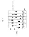
図1~3に関して、三つの異なるガラス、つまりSCHOTT AF32(登録商標)(図1)、SCHOTT D263(登録商標)(図2)およびSCHOTT BOROFLOAT(登録商標)33(図3)についてのDOE試験系列の結果が示されている。 1-3, the DOE test series for three different glasses: SCHOTT AF32® (FIG. 1), SCHOTT D263® (FIG. 2) and SCHOTT BOROFLOAT® 33 (FIG. 3). results are shown.
これは実施例の選択である。一般に、本発明は、フィラメント化を有する、ことにガラス、ガラスセラミックおよび/またはシリコンからなる異なる基材について、ことにわずかな熱膨張係数を有する材料についても使用することができる。 This is a choice of examples. In general, the invention can be used with different substrates having filamentation, in particular consisting of glass, glass-ceramic and/or silicon, in particular also with materials having a low coefficient of thermal expansion.
これらのガラスの多数の試料について、それぞれ一つのフィラメント化が行われ、つまりレーザーのレーザーパルスを用いて、分離ラインに沿って互いに離間した損傷をそれぞれの試料のバルク内へ導入した。 A number of samples of these glasses were each filamented, ie laser pulses of a laser were used to introduce spaced-apart lesions along separation lines into the bulk of each sample.
SCHOTT AF32(登録商標)またはSCHOTT D263(登録商標)からなる試料について、ことに約100μmの基材の厚みが選択され、SCHOTT BOROFLOAT(登録商標)33からなる試料について、ことに1mmの基材の厚みが選択された。 For samples consisting of SCHOTT AF32® or SCHOTT D263®, a substrate thickness of approximately 100 μm is chosen, and for samples consisting of SCHOTT BOROFLOAT® 33, a substrate thickness of in particular 1 mm is selected. thickness was selected.
フィラメント化後に、フィラメント化された分離ラインに関するガラスの破断強度σBをそれぞれ調査した。換言すると、試料を分離ラインに沿って分離し、この際に、分離のために必要な破断応力を測定しかつ記録した。このために、材料の厚みに応じて、DIN EN 843-1(比較的厚いガラス)による4点曲げ強さ試験法、または独国特許出願公開第102014110855号明細書(DE 10 2014 110 855 A1)(比較的薄いガラス)による段付きロールを用いた破断強度の決定を実施した。この独国特許出願公開第102014110855号明細書(DE 10 2014 110 855 A1)は、脆性材料の薄い帯材の縁部の破断強度の決定のための方法および装置を記載している。After filamentation, the breaking strength σB of the glass on the filamentized separating line was investigated respectively. In other words, the sample was separated along the separation line, during which the breaking stress required for separation was measured and recorded. For this purpose, depending on the thickness of the material, the four-point flexural strength test method according to DIN EN 843-1 (relatively thick glasses) or
次の工程では、試料の各々について、分離後に得られる分離端部の強度について調査した。それぞれの端部強度σKの決定のために、試料をそれぞれまた材料の厚みに応じて、DIN EN 843-1(比較的厚いガラス)または独国特許出願公開第102014110855号明細書(DE 10 2014 110 855 A1)(比較的薄いガラス)による方法を用いて調査し、結果を測定し、かつ記録した。In the next step, each of the samples was investigated for the strength of the separated edge obtained after separation. For the determination of the respective edge strength σK , the specimens are individually and depending on the thickness of the material, according to DIN EN 843-1 (relatively thick glass) or according to
この手法により得られた破断応力σBおよび端部強度σKは、図1~3において、縦軸にMPaの単位でプロットされている。破断応力σBは、図面の下側にBによって表されていて、端部強度σKは、相応してKにより示されている。The rupture stress σB and edge strength σK obtained by this technique are plotted in units of MPa on the vertical axis in FIGS. The breaking stress σB is denoted by B at the bottom of the drawing and the edge strength σK is denoted by K correspondingly.
レーザーフィラメント化は、このために多様なパラメーターで実施され、つまり異なるようにパーフォレーションされた試料を作成した。隣接する損傷の間の間隔およびそれぞれ一つの損傷を作成するためのレーザーパルスの数を変更した。これらのパラメーターは、それぞれ一つの試料に対して調節され、かつ所定の試料のフィラメント化の間、一定に保持された。 Laser filamentation was performed for this purpose with various parameters, ie to produce differently perforated samples. The spacing between adjacent lesions and the number of laser pulses to create each single lesion were varied. These parameters were each adjusted for one sample and held constant during the filamentation of a given sample.
図1~3において、破断応力σBおよび端部強度σKは、したがって、横軸にプロットされているレーザーフィラメント化の多様なパラメーターに対して示されている。この場合、マイクロメートルで表される隣接する損傷の間の間隔はAで示され、かつそれぞれ一つの損傷を作成するためのレーザーパルス数はLで示されている。In FIGS. 1-3, the breaking stress σB and the edge strength σK are thus shown for various parameters of laser filamentation plotted on the horizontal axis. In this case, the spacing between adjacent lesions, expressed in micrometers, is denoted by A, and the number of laser pulses for creating each lesion is denoted by L.
示された試験結果に基づいて、フィラメント化に引き続く分割工程にとって、分離ラインに沿った分離のための破断応力σBに関しておよび分離後に得られる分離端部の端部強度σKに関してフィラメント化のプロセスパラメーターAおよびLを調節することが特に有利であることを確かめることができる。Based on the test results presented, for the splitting step subsequent to filamentation, the process of filamentation with respect to the breaking stressσ for splitting along the splitting line and with respect to the edge strengthσK of the split edge obtained after splitting. It can prove to be particularly advantageous to adjust the parameters A and L.
次に、ことに、分離ラインに沿ってガラスを分離するための破断応力σBは、それぞれのガラスに依存する第一の基準応力σR1よりも小さく、かつ分離後に得られる分離端部の端部強度σKは、それぞれのガラスに依存する第二の基準応力σR2よりも大きく調節することが特に有利であることが明らかになり、この場合、例えばことに、σR1=σR2=σthが当てはまる場合が好ましいことが明らかになるという認識を確かめることができ、この場合、σthは、例えば
σth=0.5・α・E・(Tg-100℃)
と仮定することができる最大熱応力である。Then, in particular, the breaking stress σB for separating the glasses along the separation line is less than the respective glass-dependent first reference stress σR1 and the edge of the separation edge obtained after separation It has proven particularly advantageous to set the part strength σK to be greater than the respective glass-dependent second reference stress σR2 , in which case, for example, in particular σR1 =σR2 =σ One can confirm the recognition that it turns out to be favorable ifth holds, in which case σth is for example σth =0.5·α·E·(Tg −100° C.)
is the maximum thermal stress that can be assumed.
図1~3には、それぞれのガラスに対して所定の最大熱応力0.5・α・E・(Tg-100℃)が計算され、かつ水平線として表されている。A predetermined maximum thermal stress of 0.5·α·E·(Tg −100° C.) was calculated for each glass and represented as a horizontal line in FIGS.
三つの全てのガラス、つまりSCHOTT AF32(登録商標)(図1)、SCHOTT D263(登録商標)(図2)およびSCHOTT BOROFLOAT(登録商標)33(図3)についてのこれらの値は、測定された破断応力σBおよび端部強度σKのオーダーにあり、かつしたがって、プロセスパラメーターAおよびLをこの値に関して最適化して選択する可能性が生じることが明らかとなる。These values for all three glasses, namely SCHOTT AF32® (Fig. 1), SCHOTT D263® (Fig. 2) and SCHOTT BOROFLOAT® 33 (Fig. 3), were measured It becomes apparent that the breaking stress σB and the edge strength σK are of the order and therefore the possibility arises to select the process parameters A and L optimized with respect to this value.
SCHOTT AF32(登録商標)ガラスに基づく図1で示された試験結果から、ことに0.5・α・E・(Tg-100℃)の値に関して破断応力σBを最小化しかつ他方で端部強度σKを最大化するために、ことに7μmの損傷間隔と8のレーザーパルス数との組合せが特に適していることを認識することができる。From the test results shown in FIG. 1 on SCHOTT AF32® glass, it can be seen that the breaking stress σB is minimized, especially for values of 0.5·α·E·(Tg −100° C.) and on the other hand the edge It can be seen that the combination of a lesion spacing of 7 μm and a laser pulse number of 8 is particularly suitable for maximizing the spot intensity σK .
SCHOTTガラスD263(登録商標)については、図2から、7μmの損傷間隔と2のレーザーパルス数との組合せが特に適したパラメーターであることが推知できる。 For SCHOTT glass D263®, it can be deduced from FIG. 2 that a combination of a damage spacing of 7 μm and a laser pulse number of 2 is a particularly suitable parameter.
図3から、SCHOTTガラスBOROFLOAT(登録商標)33について、パルス数4と損傷間隔7μmとの組合せか、またはパルス数8と損傷間隔5μmもしくは7μmとの組合せが特に適したパラメーターであることが推知できる。 From FIG. 3 it can be deduced that for SCHOTT glass BOROFLOAT® 33, a pulse number of 4 in combination with a lesion spacing of 7 μm or a pulse number of 8 in combination with a lesion spacing of 5 μm or 7 μm are particularly suitable parameters. .
したがって、破断応力に関するフィラメントの最適化により、引き続く分離プロセス(分割工程)は熱により誘導された応力によって最適化されて実施することができる。 Thus, by optimizing the filament with respect to breaking stress, the subsequent separation process (splitting step) can be performed optimized with thermally induced stress.
これらの試験は、ことに、意外にも、比較的大きな間隔を有するパーフォレーションが、分離可能性において材料に広がる利点をもたらすことを示す。 These tests show, among other things, that perforations with a relatively large spacing provide a material widening advantage in separability.
これには、比較的高いプロセス信頼性が含まれる:限界値のプロセスウィンドウの場合でさえ、つまり先行技術から今までは確実には導き出すことができなかったパラメーター範囲を用いたプロセスの場合でさえ、本発明による方法を用いて、基材を確実に分離することができる。 This includes a relatively high process reliability: even in the case of marginal process windows, i.e. processes with parameter ranges that so far could not be reliably derived from the prior art. , the substrate can be reliably separated using the method according to the invention.
このため、レーザーを低減された出力で作動させることができ、かつ/またはレーザーの走行速度(送り速度)を適合することができ、ことに高めることができる。例えば、5μmのパーフォレーション間隔を有する材料の場合、40mm/sの送りのプロセス設定で、レーザー出力を110Wから75Wに低減することができた。 For this reason, the laser can be operated with a reduced power and/or the running speed (feed rate) of the laser can be adapted and, in particular, increased. For example, for a material with a perforation spacing of 5 μm, the laser power could be reduced from 110 W to 75 W at a process setting of 40 mm/s feed.
一適用例の場合に、SCHOTT BOROFLOAT(登録商標)33からなり、1mmの厚み、3.3・10-6K-1のCTEの試料を、7μmの損傷の間隔で、それぞれ一つの損傷を作製するために300kHzで6のレーザーパルスで、かつ2100mm/sの送り速度でフィラメント化した。In one application, specimens of
他の利点は、分離端部の造形に関して生じる。分割工程での比較的低い応力に基づいて、複雑な幾何学形状、例えば小さなコーナー半径を製造できる。 Another advantage arises with respect to the shaping of the split ends. Complex geometries, such as small corner radii, can be produced due to the relatively low stresses in the splitting process.
さらに、端部品質を改善することができる:端部の欠けや微小亀裂は、回避されるかまたは視覚的にも顕微鏡によっても知覚することができない。このことは、ことに端部強度に対して好ましく作用する。 Furthermore, the edge quality can be improved: edge chips and microcracks are avoided or cannot be perceived visually or microscopically. This has a particularly favorable effect on the edge strength.
図4には、例として、多様なプロセスパラメーターに対して、1mmの厚みを有するSCHOTT BOROFLOAT(登録商標)33についての端部粗さが示されている。レーザーパルスの数Lは、この図中ではバーストで示されている。損傷の間隔が増大すると共に、同じレーザーパルス数で端部粗さは低下することが明らかである。 In FIG. 4, by way of example, the edge roughness for a SCHOTT BOROFLOAT® 33 with a thickness of 1 mm is shown for various process parameters. The number L of laser pulses is indicated in bursts in this figure. It is clear that edge roughness decreases with the same number of laser pulses as the distance between lesions increases.
次の表中に、先の文面中に述べられたSchottガラスAF32(登録商標)、D263(登録商標)およびBOROFLOAT(登録商標)33の特性が詳細に列挙されている。 In the following table the properties of the Schott glasses AF32®, D263® and BOROFLOAT® 33 mentioned in the previous text are listed in detail.
表1:SCHOTT AF32(登録商標)の特性
表2:SCHOTTガラスD263(登録商標)の特性
表3:SCHOTT BOROFLOAT(登録商標)33の特性
交差する分離ラインが設けられている場合、分割の際に亀裂が予定された分離ラインに従って分離しないか、または亀裂は始まらないかもしくは破断しないという問題が、深刻化する。互いに角度が付けられて配置されかつフィラメントからなる分離ラインを有する基材を熱により誘導された応力によって分離する場合、分離ラインの交差点でしばしば、潜在的に全ての方向に亀裂形成が進行するという問題が生じる。分離ラインを、(例えば中間段階の洗浄、被覆などを有する)多段階プロセスの範囲内で、後に複数の部材片に分離もしくは個別化するために破断準備として利用する場合、予め加工された基材は、しばしば、分離ラインの交差点に初期亀裂が設けられている。この場合、後に(例えば、洗浄および被覆のようなさらなるプロセス段階の後で)初めて分離されるべき分離ラインにも初期亀裂形成が設けられる。それにより、分離ラインは後続加工プロセスにおいて制御不能に破断されるという危険が高まる。 If intersecting parting lines are provided, the problem that during splitting the crack does not separate according to the intended parting line or does not initiate or break, is exacerbated. It is said that when substrates that are arranged at an angle to each other and have separation lines of filaments are separated by thermally induced stress, crack formation can potentially progress in all directions, often at the intersection of the separation lines. A problem arises. Prefabricated substrates when the separating line is used as break preparation for subsequent separation or singulation into multiple pieces within the scope of a multi-step process (e.g. with intermediate washing, coating, etc.) are often provided with initial cracks at the intersection of the separation lines. In this case, the separation lines to be separated only later (eg after further process steps such as cleaning and coating) are also provided with initial crack formation. This increases the risk that the separating line will break uncontrollably in subsequent machining processes.
一般に、この場合にも、本発明は、正確に調節された破断応力に基づいて、予定された分離ラインが、互いに離間した損傷を有する他の分離ラインと交差する場合であっても、予定されたラインに沿った分離を可能にするために特に適している。したがって、本発明の発展形態の場合に、本発明により加工されたワークピースは、互いに離間した損傷を有する少なくとも二つの互いに交差する分離ラインを有するか、または基材中に離間した損傷を有する少なくとも二つの互いに交差する分離ラインが作製されることが予定されている。 In general, again in this case, the present invention provides a pre-determined separation line based on a precisely adjusted breaking stress, even if the pre-determined separation line intersects another separation line with damage that is spaced apart from each other. It is particularly suitable for enabling separation along a line. Therefore, in the case of a development of the invention, the workpiece machined according to the invention has at least two mutually intersecting separation lines with spaced-apart damages or at least two spaced-apart damages in the substrate. It is envisaged that two mutually intersecting separating lines will be made.
交差する分離ラインの場合、ワークピースに、異なる高さの応力で分離することができる異なる分離ラインを設けることが有利である。 In the case of intersecting separation lines, it is advantageous to provide the workpieces with different separation lines that can be separated at different heights of stress.
したがって、一般に、特別な実施例に限定されることなく、本発明の他の態様によると、少なくとも二つの分離ラインに沿って予め損傷されていて、この分離ラインは交差しているため、ワークピースは破断応力を加えることによりこれらの分離ラインに沿って分離可能である、ワークピース、ことにガラス製品、ガラスセラミック製品および/またはシリコン製品が予定されていて、この場合、分離ラインまたは変性ラインで分割するためのこれらの破断応力は、少なくとも3MPa、好ましくは少なくとも5MPa、特に好ましくは少なくとも10MPa異なる。 Thus, generally, and without being limited to a particular embodiment, according to another aspect of the invention, the workpiece is pre-damaged along at least two separation lines, the separation lines intersecting so that the workpiece is is intended for workpieces, in particular glassware, glass-ceramic articles and/or silicon articles, which can be separated along these separation lines by applying a breaking stress, in this case in a separation line or a modification line. Their breaking stresses for splitting differ by at least 3 MPa, preferably by at least 5 MPa and particularly preferably by at least 10 MPa.
この場合、最初に分離されるべき分離ラインの主要構造は、後に分離されるべき分離ラインよりも明らかに低い応力を有する場合が特に有利である。 In this case it is particularly advantageous if the main structure of the separating line to be separated first has a significantly lower stress than the separating line to be separated later.
一般に、ワークピースは、また、分離ラインに沿って互いに離間した損傷を有し、ここで、この分離ラインに沿ってワークピースを分離するための破断応力σBは、それぞれのワークピースに依存する第一の基準応力σR1よりも小さく、かつ分離後に得られる分離端部の端部強度σKは、それぞれのワークピースに依存する第二の基準応力σR2よりも大きいことが好ましい。この場合、他の分離ラインの破断応力は、相応して、少なくとも3MPa高いかまたは低い。特に好ましくは、この第二の破断応力はより高い。Generally, the workpieces also have damage spaced apart from each other along a separation line, where the breaking stress σB for separating the workpieces along this separation line depends on the respective workpiece. Preferably, the edge strength σK of the separated edge obtained after separation is less than the first reference stress σR1 and greater than the respective workpiece-dependent second reference stress σR2 . In this case, the breaking stress of the other separating lines is correspondingly higher or lower by at least 3 MPa. Particularly preferably, this second breaking stress is higher.
異なる破断応力は、好ましくはレーザーパラメーターの変更により調節することができるので、超短パルスレーザーを用いて製造された分離ラインのここに記載された全ての特徴が、交差する分離ラインを有するこの実施形態についても当てはまる。しかしながら、交差する分離ラインに沿った損傷を他の手法で製造することも考えられる。したがって、本発明のこの実施形態は、必ずしもフィラメント状の損傷の導入またはレーザー加工に限定されるものではない。 Since the different breaking stresses can preferably be adjusted by changing the laser parameters, all the features described here of the separation lines produced using an ultrashort pulse laser are in this implementation with intersecting separation lines. The same applies to form. However, it is also conceivable to produce lesions along intersecting separation lines in other ways. Therefore, this embodiment of the invention is not necessarily limited to the introduction of filamentary damage or laser processing.
図5は、上述のように二つの分離ライン3,5を有するワークピースまたは基材1を示す。好ましくは、基材1は、一般に、示された例に限定されることなく、板状であり、かつしたがって対向する、一般に互いに平行に延びる二つの側面10,11を有する。記載された方法によって、超短パルスレーザーを用いてフィラメント状の損傷7を基材1内に導入した。この場合、レーザー光は、側面10,11の一方に入射するので、フィラメント状の損傷7は、放射方向に即して、両方の側面10,11の間に広がる。分離ライン3,5は、示された例の場合に直角で交差していて、これは、長方形の部材を分離するためにも好ましい。 Figure 5 shows a workpiece or
図5に基づいて認識できるように、分離ライン3,5に沿ったフィラメント状の損傷7の間隔a1,a2は異なる。示された例の場合に、分離ライン3に沿ったフィラメント状の損傷の間隔a1は、分離ライン5に沿ったフィラメント状の損傷の間隔a2よりも小さい。このため、分離ライン3で分離するための破断応力σB1は、分離ライン5で分離するための破断応力σB2とは異なる。上述の観察によれば、分離ライン3のための破断応力は、よりわずかな間隔a1により、より高いかまたはより低くてよい。典型的には、破断応力の最小値は、5~7μmの範囲内のフィラメントラインの間隔の場合に観察される。したがって、一般に、示された例に限定されることなく、フィラメント状の損傷の間隔が異なり、分離ライン3の一方の間隔は、互いに交差する分離ラインの他方の間隔よりも小さい、ワークピース、もしくは基材1が予定されている。As can be recognized on the basis of FIG. 5, the spacings a1, a2 of the
他の実施形態の場合に、ワークピースまたは基材1は、図5に示されたような少なくとも二つの異なる分離ラインにより特徴付けられ、分離ライン3に沿ってワークピース1を分離するための破断応力σB1は、それぞれのワークピースに依存する第一の基準応力σR1よりも小さく、分離後に生じる分離端部の端部強度σKは、それぞれのワークピースに依存する第二の基準応力σR2よりも大きく、かつ第二の分離ライン5は、少なくともσB1+5MPa、好ましくはσB1+10MPa、好ましくはσB1+15MPaの明らかにより高い破断応力を有する。好ましくは、第二の分離ラインは、それに所属する破断応力がσR1を超えることが際立っている。In another embodiment, the workpiece or
他の実施形態の場合に、基材には、後の個別化のための多数の分離ラインが設けられていて、同じ方向の分離ラインは、同じレーザープロセスパラメーターを用いて作成され、したがって同じ破断応力を有し、かつ異なる方向の分離ラインの間に異なる破断応力が存在するだけである。換言すると、二つより多くの互いに交差する分離ラインが予定され、分離ラインの集合は、並んで延びる分離ラインの少なくとも二つの群に区分けすることができ、一方の群の分離ラインの平均破断力は、他方の群の平均破断力とは、少なくとも3MPaの上述の値だけ相違する。このようなワークピースまたは基材1の例は、図6に示す。複数の分離ライン3が互いに平行に延び、したがって側面10に沿って並んでいる。これらの分離ライン3は、同様に互いに平行に延びる分離ライン5と交差している。図5に示された例の場合のように、分離ライン3,5は直角に交差している。平行に延びる分離ライン3の集合は、分離ラインの第一の群30を形成し、これに対して垂直に延びる分離ライン5は、他の群50を形成する。群30,50は、これらの分離ラインが、それぞれ同じように離間するが、他の群の分離ラインとは異なるように離間するフィラメント状の損傷7を有することを特徴とする。したがって、群30の分離ライン3の破断応力はまた、値σB1を有し、この値は、他の群50の分離ライン5の値σB2とは異なる。In another embodiment, the substrate is provided with multiple separation lines for subsequent singulation, and separation lines of the same direction are produced using the same laser process parameters and thus the same fracture There are only different breaking stresses between separation lines that have stress and are in different directions. In other words, more than two mutually crossing parting lines are provided, the set of parting lines can be divided into at least two groups of parting lines running side by side, the average breaking force of the parting lines of one group differs from the average breaking force of the other group by the abovementioned value of at least 3 MPa. An example of such a workpiece or
原則として、分離ラインに沿った破断応力を変更する、もしくは調節するいくつかの可能性がある。例えば、フィラメントの形成のために使用されるバーストパルスの数を変えてもよい(1~100パルスの範囲内、好ましくは2~20パルスの範囲内)。単一パルスまたはバーストパルスのパルスエネルギーを、単一パルスについては100μJ~1mJの範囲内で、バーストパルスの場合には400μJ~4mJの範囲内で変更してもよい。さらに、これらの図で示されたように、フィラメント7の間隔を、個々の分離ライン3,5の中で、1μm~25μmの範囲内、特に好ましくは2μm~20μmの範囲内の多様な値に変えてよいため、異なる間隔の値a1およびa2が生じる。In principle there are several possibilities to modify or adjust the breaking stress along the separation line. For example, the number of burst pulses used for filament formation may vary (within the range of 1-100 pulses, preferably in the range of 2-20 pulses). The pulse energy of the single or burst pulses may vary within the range of 100 μJ to 1 mJ for single pulses and within the range of 400 μJ to 4 mJ for burst pulses. Furthermore, as shown in these figures, the spacing of the
例えば、0.5mmの厚みのアルカリホウケイ酸ガラスについて、300μJのバーストエネルギーを400μJに変更することにより(100kHzの反復率および10psパルス時間を有するUSPレーザーの場合)、25MPaの破断力を約15MPaに低下させることにより異なる破断応力の分離ラインの系を作製することができる。さらに、ピッチ間隔の増大は、分離プロセスにとって必要な破断応力の約5MPaの低下を引き起こす:導入された変性の間の5μmのピッチの場合、上述のようなガラスにおいて約45MPaの破断応力を生じ、10μmの間隔の場合の破断応力はわずか15MPaである。 For example, for a 0.5 mm thick alkali borosilicate glass, changing a burst energy of 300 μJ to 400 μJ (for a USP laser with a repetition rate of 100 kHz and a 10 ps pulse time) reduces the breaking force of 25 MPa to about 15 MPa. A system of separation lines of different breaking stresses can be produced by lowering. Furthermore, increasing the pitch spacing causes a reduction in the breaking stress required for the separation process of about 5 MPa: for a pitch of 5 μm during the introduced modification, a breaking stress of about 45 MPa results in the glass as described above, The breaking stress for a spacing of 10 μm is only 15 MPa.
基材1は、分離ラインの導入後に、二段階の個別化プロセスにより、まず、第一の方向に沿った破断により、引き続き第二の方向に沿った破断により個別化することができる。この場合に、部材片の隣接する端部は、異なるように離間する周期構造(フィラメント通路の開口により二つの半円筒形)を有し、この周期構造は、触覚的または光学的プロフィロメトリーまたは電子顕微鏡のような通常のトポロジー測定法により求められる。ワークピース1から分離された相応するエレメント2は、図7に示されている。 After introduction of the separating line, the
概略図に基づいて明らかなように、二つの対向する側面10,11、ならびに端面13,14,15,16を有する板状のガラスエレメントまたはガラスセラミックエレメント2が準備され、ここで、端面13,14,15,16の少なくとも二つは、フィラメント状の損傷7を有し、このフィラメント状の損傷は、周期的間隔で側面10,11の一方から側面の他方に向かう方向で互いに並んで端面上に延び、ここで、フィラメント状の損傷の間隔の周期は、端面13,14,15,16の少なくとも二つで互いに異なる。 As can be seen from the schematic illustration, a plate-like glass or glass-
好ましくは、図示された例の場合でも、一般に四角形の形状であるので、エレメント2は、対向する端面13,15および14,16の二つのペアを有する。この場合、フィラメント状の損傷7の周期は、対向する端面の一つのペアの場合に、好ましくはそれぞれ同じである。フィラメント状の損傷の周期もしくは間隔、エレメント2の厚み、およびその材料に関しては、本発明による方法およびそれにより製造可能なワークピースについてここで開示された全ての記載が相応して当てはまる。 Preferably, the
一般性に制限されずに、分離は、機械的破断プロセスまたはレーザーに基づく熱的分離プロセス(CO2レーザーを用いる)または他の方法により実施されてよい。Without being limited in generality, separation may be performed by a mechanical fracture process or a laser-based thermal separation process (using aCO2 laser) or other methods.
他の実施形態の場合に、個別のストリップ(同じ破断応力の対向する端面により形成される)は、一つの共通するウェブを介して相互に結合されたままであり、このウェブは、洗浄、被覆および後の個別化のような後続するプロセス段階のためのハンドリング補助部として使用されてよい。このようなワークピース1についての実施例を図8が示す。例示的な図に基づき明らかなように、群50の一方の分離ライン5は、ワークピース1の端部の一方の前で終端しているので、ワークピース1が端部20の前で終端する分離ライン5で分離される場合であっても、分離ライン5の終端とワークピースの端部20との間にウェブ18が形成され、このウェブに接して分離可能なエレメント2が固定されて残る。 In another embodiment, the individual strips (formed by opposing end faces of the same breaking stress) remain connected to each other via one common web, which web is cleaned, coated and It may be used as a handling aid for subsequent process steps such as later singulation. An example for such a
他の実施形態の場合に、分離のために準備されたワークピース1は、取り囲むフレームを有し、このフレームから、個別化の際に、全体のストリップまたは個々の断片を破断することができる。フレーム22を有するこの実施形態を図9が示す。この場合、個別化プロセスにおいてハンドリングフレームは、全体として保持されたままにしてよいかまたは段階的に分解されてもよい。図8による実施形態のウェブ18の場合のように、この群の一方の分離ラインは、ワークピース1の端部20の前で終端する。フレーム22の場合には、このことが、両方の群30,50について当てはまる。 In another embodiment, the
フィラメント化された分離ラインが例えば部分的にハンドリングフレームまたはハンドリングストリップ内に突き出ている他の変形形態も同様に考えられる。これについての例を図10が示す。この例の場合に、フレーム22の一方の側は、分離ライン5の終端の端部20に対する間隔により決定され、フレームの他方の側は、分離ライン3,5の縦方向側によって区切られる。 Other variants are likewise conceivable, in which the filamentized separating line protrudes, for example, partially into the handling frame or handling strip. An example of this is shown in FIG. In this example, one side of the
図11は、本発明によるワークピース1を例えば工業的後続加工のために取り扱うことができ、かつこの場合に分離ライン3,5での予定前の分離を回避する例を示す。この例の場合に、ワークピース1は、その側面の一方11で支持体24上に固定される。支持体24は、例えばガラスウェハまたはシリコンウェハまたはポリマー、もしくはプラスチックプレートであってよい。 FIG. 11 shows an example in which
図6の実施形態の場合に、フィラメント状の損傷7の間隔および破断応力は群ごとに異なり、ここでこれらの群は、互いに並んで延びかつ交差していない分離ラインにより形成される。これは、互いに並んで延びる分離ラインの一つ以上に、他の、ことに低い破断応力を付与することを排除しない。例えば、他の実施形態の場合に、基材またはワークピース1は、破断応力の適切な選択により、それ自体また分割することができるいくつかのより大きな部材片に区分される。この区分は、実際の切り離しである必要はなく、ことに部材片の間の分離ラインでワークピースを区分けすることであると解釈される。図12で示された実施例の場合に、ワークピース1は、分離ライン6で二つの部材片8,9に区分けされる。 In the case of the embodiment of FIG. 6, the spacing and breaking stress of the
例えばn番目毎の平行な分離ラインだけが同じ破断応力を有し、その間の分離ラインは他の破断応力値を有する。この場合、平行な分離ラインとそれに対して垂直の分離ラインとの任意の組合せが可能である。破断応力の変更は、それぞれ、上述のように、パルスエネルギー、バースト数または導入された変性の間隔の変更によって可能である。部材片の間の境界での分離ラインが、隣接する分離ラインよりも高い破断応力を有する区分も考えられる。まず部材片8,9に分離し、次いでさらに個々のエレメント2に分離することを可能にするためには、しかしながら、分離ライン6について、部材片8,9内の隣接する分離ラインよりも低い破断応力に調節することが特に好ましい。したがって、本発明のこの実施形態の場合に、ワークピース1はいくつかの互いに並んで延びる分離ライン5,6を有し、ここで、分離ライン6の少なくとも一つが、二つの隣接する分離ライン5の間に延び、かつ、ここで、両方の隣接する分離ライン5の間に延びる分離ラインは、隣接する分離ライン5よりも低い破断応力を有することが予定されている。好ましくは、図示の例のように、より低い破断応力を有する分離ライン6の両側に、より高い破断応力を有する分離ライン5の二つの群が延びる。この破断応力の相違は、一般に、交差する分離ラインを有する実施形態の場合と同様に、好ましくは少なくとも3MPa、ことに少なくとも5MPaであるように選択されてよい。 For example, only every nth parallel separating line has the same breaking stress, and separating lines in between have other breaking stress values. In this case any combination of parallel and perpendicular separation lines is possible. Modification of the breaking stress is possible by varying the pulse energy, the number of bursts or the interval of induced modification, respectively, as described above. Sections are also conceivable in which the parting line at the boundary between the pieces has a higher breaking stress than the adjacent parting line. In order to be able to separate first into
ここに記載された全てのワークピースは、原則として、被覆された基材であってもよい。この場合、被覆は、場合により分離ラインのレーザーアシストされた導入の前に施されてもよい。被覆として、本発明の一実施形態の場合には、タンパク質分析またはDNA分析用の有機官能被覆が施されていてよい。したがって、ワークピース1、またはワークピース1から製造可能なエレメント2は、DNAマイクロアレイまたはタンパク質マイクロアレイとして使用されてよい。このために適切な被覆は、アミノシラン、エポキシシラン、アルデヒドシラン、ヒドロゲル、ストレプトアビジン、ならびに所定のポリマーである。この場合、被覆には、オリゴヌクレオチド、cDNA/PCR、BAC(細菌人工染色体(Bacterial Artificial Chromosomes))、ペプチド、タンパク質、抗体、グリカン、または細胞試料もしくは組織試料からなるマイクロアレイが設けられていてよい。これらの試料は、この手法で共通して作成され、かつ次いで分割後に別個に検査および/または出荷することができる。 All workpieces described herein can in principle be coated substrates. In this case, the coating may optionally be applied prior to the laser-assisted introduction of the separation line. As a coating, in one embodiment of the invention, an organofunctional coating for protein analysis or DNA analysis may be applied. Thus, the
1 ワークピース
2 エレメント
3,5,6 分離ライン
7 フィラメント状の損傷
8,9 1の部材片
10,11 1の側面
30,50 分離ラインの群
13,14,15,16 端面
18 ウェブ
20 1の端部
22 フレーム
24 支持体1
Claims (21)
Translated fromJapanese予定された分離ラインに沿って少なくとも一つのパルスレーザービームを用いて互いに離間した損傷を前記基材内に導入し、
隣接する損傷の間の平均間隔、ならびにそれぞれ一つの損傷を作製するためのレーザーパルスの数を、
a)前記分離ラインに沿って前記基材(1)を分離するための破断応力σBは、それぞれの基材に依存する第一の基準応力σR1よりも小さく、
b)前記分離後に得られる分離端部の端部強度σKは、それぞれの基材に依存する第二の基準応力σR2よりも大きく、かつ
c)前記基材は、前記損傷の導入後に、前記分離ラインに沿った応力の作用により分離可能である
ように選択し、前記第一の基準応力と前記第二の基準応力とは同じでありσR1=σR2、かつ(i)前記基材の材料に依存する最大熱応力σthとして予め設定されているか、または、(ii)予め応力がかけられた基材に対して、予め応力がかけられた基材の特性により定義される内部引張応力σCTとして予め設定されており、
前記第一の(i)の場合、前記最大熱応力σthは、式
σth=0.5・α・E・(Tg-100℃)により決定され、この場合、αは、前記基材の材料の熱膨張係数を表し、Eは、前記基材の材料の弾性率を表し、Tgは、前記基材の材料のガラス転移温度を表し、
前記第二の(ii)の場合、前記内部引張応力σCTは、化学的に予め応力がかけられた基材については、式σCT=(σCS・dL)/(d-2dL)により決定され、熱的に予め応力がかけられた基材については、式σCT=σCS/2により決定され、この場合、σCSは、前記予め応力がかけられた基材の表面圧縮応力を表し、dLは、予めかけられた応力の侵入深さを表し、dは、前記基材の厚みを表す、基材(1)の分離方法。In a method for separating substrates (1), in particular substrates made of brittle hard materials, in particular glass, glass-ceramic and/or silicon,
introducing spaced apart lesions into the substrate using at least one pulsed laser beam along a predetermined separation line;
the average spacing between adjacent lesions, as well as the number of laser pulses to create each single lesion,
a) the breaking stress σB for separating the substrates (1) along the separation line is less than the respective substrate-dependent first reference stress σR1 ,
b) the edge strengthσK of the split edge obtained after said splitting is greater than the respective substrate-dependent second reference stressσR2 , and c) said substrate, after introduction of said damage, is: selected to be separable by action of stress along said separation line, said first reference stress and said second reference stress being the same and σR1 =σR2 , and (i) said substrate or (ii) for the pre-stressedsubstrate , the internal tension defined by the properties of the pre-stressed substrate It is preset as stress σCT ,
In the first (i) case, the maximum thermal stress σth is determined by the formula σth =0.5·α·E·(Tg −100° C.), where α is the substrate represents the coefficient of thermal expansion of the material of the substrate, E represents the modulus of elasticity of the material of the substrate,T represents the glass transition temperature of the material of the substrate,
In the second (ii) case, the internal tensile stress σCT is given by the formula σCT =(σCS dL )/(d−2dL ) for a chemically prestressed substrate for a thermally prestressed substrate, determined by the formula σCT =σCS /2, where σCS is the surface compressive stress of said prestressed substrate , dL representing the penetration depth of the pre-applied stress and d representing the thickness of said substrate (1).
隣接する損傷の間の平均間隔は、範囲[6μm,8μm]から選択され、かつそれぞれ一つの損傷を作製するためのレーザーパルスの数は、範囲[7,9]から選択される、
請求項1から5までのいずれか1項記載の方法。The material of the substrate has a coefficient of thermal expansion in the range [3·10−6 K−1 , 4·10−6 K−1 ], an elastic modulus in the range [69 kN/mm2 , 76 kN/mm2 ] and/or having a glass transition temperature in the range [700°C, 800°C], and the average spacing between adjacent lesions is selected from the range [6 µm, 8 µm], and the number of laser pulses to create each single lesion the number is selected from the range [7,9];
A method according to any one of claims 1 to 5.
隣接する損傷の間の平均間隔は、範囲[6μm,8μm]から選択され、かつそれぞれ一つの損傷を作製するためのレーザーパルスの数は、範囲[1,3]から選択される、
請求項1から6までのいずれか1項記載の方法。The material of the substrate has a coefficient of thermal expansion in the range [7·10−6 K−1 , 8·10−6 K−1 ], an elastic modulus in the range [69 kN/mm2 , 76 kN/mm2 ] and/or having a glass transition temperature in the range [500° C., 600° C.] and the average spacing between adjacent lesions is selected from the range [6 μm, 8 μm] and the number of laser pulses to create each one lesion the number is selected from the range [1,3];
A method according to any one of claims 1 to 6.
隣接する損傷の間の平均間隔は、範囲[4μm,8μm]から選択され、かつそれぞれ一つの損傷を作製するためのレーザーパルスの数は、範囲[7,9]から選択されるか、または隣接する損傷の間の平均間隔は、範囲[6μm,8μm]から選択され、かつそれぞれ一つの損傷を作製するためのレーザーパルスの数は、範囲[3,5]から選択される、
請求項1から7までのいずれか1項記載の方法。The glass has a coefficient of thermal expansion in the range [3·10−6 K−1 , 4·10−6 K−1 ], a modulus of elasticity in the range [60 kN/mm2 , 68 kN/mm2 ] and/or a range [500 °C, 600 °C], and the average spacing between adjacent lesions is selected from the range [4 µm, 8 µm], and the number of laser pulses to create each single lesion is The average spacing between adjacent lesions is selected from the range [7, 9], or the average spacing between adjacent lesions is selected from the range [6 μm, 8 μm], and the number of laser pulses to create each single lesion is selected from the range selected from [3,5],
A method according to any one of claims 1 to 7.
前記ワークピースは、前記分離ラインに沿って互いに離間した損傷を有し、かつ
前記分離ラインに沿って前記ワークピースを分離するための破断応力σBは、それぞれのワークピースに依存する第一の基準応力σR1よりも小さく、かつ
前記分離後に得られる分離端部の端部強度σKは、それぞれのワークピースに依存する第二の基準応力σR2よりも大きく、
前記第一の基準応力と前記第二の基準応力とは同じでありσR1=σR2、かつ(i)前記基材の材料に依存する最大熱応力σthとして予め設定されているか、または、(ii)予め応力がかけられた基材に対して、予め応力がかけられた基材の特性により定義される内部引張応力σCTとして予め設定されており、
前記第一の(i)の場合、前記最大熱応力σthは、式
σth=0.5・α・E・(Tg-100℃)により決定され、この場合、αは、前記基材の材料の熱膨張係数を表し、Eは、前記基材の材料の弾性率を表し、Tgは、前記基材の材料のガラス転移温度を表し、
前記第二の(ii)の場合、前記内部引張応力σCTは、化学的に予め応力がかけられた基材については、式σCT=(σCS・dL)/(d-2dL)により決定され、熱的に予め応力がかけられた基材については、式σCT=σCS/2により決定され、この場合、σCSは、前記予め応力がかけられた基材の表面圧縮応力を表し、dLは、予めかけられた応力の侵入深さを表し、dは、前記基材の厚みを表す、ワークピース。In workpieces, in particular glass, glass-ceramic and/or silicon products, which have been previously damaged along the separation line,
The workpieces have damage spaced apart from each other along the separation line, and the breaking stress σB for separating the workpieces along the separation line is a respective workpiece-dependent first the edge strengthσK of the separated edge obtained after said separation is less than the reference stressσR1 and greater than a second reference stressσR2 depending on the respective workpiece,
the first reference stress and the second reference stress are the same and preset as σR1 =σR2 , and (i) a maximum thermal stress σth that depends on the material of the substrate, or (ii) preset to the pre-stressed substrate as an internal tensile stressσ defined by the properties of the pre-stressed substrate;
In the first (i) case, the maximum thermal stress σth is determined by the formula σth =0.5·α·E·(Tg −100° C.), where α is the substrate represents the coefficient of thermal expansion of the material of the substrate, E represents the modulus of elasticity of the material of the substrate,T represents the glass transition temperature of the material of the substrate,
In the second (ii) case, the internal tensile stress σCT is given by the formula σCT =(σCS dL )/(d−2dL ) for a chemically prestressed substrate for a thermally prestressed substrate, determined by the formula σCT =σCS /2, where σCS is the surface compressive stress of said prestressed substrate where dL represents the penetration depth of the pre-applied stress and d represents the thickness of said substrate.
前記最大熱応力σthは、ことに式σth=0.5・α・E・(Tg-100℃)により決定され、この場合、αは、前記ワークピースの材料の熱膨張係数を表し、Eは、前記ワークピースの材料の弾性率を表し、Tgは、前記ワークピースの材料のガラス転移温度を表す、
請求項9記載のワークピース。the first reference stress and the second reference stress are preset as σR1 =σR2 , a maximum thermal stress σth dependent on the material of the workpiece;
Said maximum thermal stress σth is determined in particular by the formula σth =0.5·α·E·(Tg −100° C.), where α represents the coefficient of thermal expansion of the material of said workpiece. , E represents the modulus of elasticity of the material of the workpiece andT represents the glass transition temperature of the material of the workpiece;
10. A workpiece according to claim9 .
前記第一の基準応力と前記第二の基準応力とは同じでありσR1=σR2、かつ予め応力がかけられたワークピースの特性により定義される内部引張応力σCTとして予め設定されていて、
前記内部引張応力σCTは、式σCT=(σCS・dL)/(d-2dL)により決定され、この場合、σCSは、前記予め応力がかけられたワークピースの表面圧縮応力を表し、dLは、予めかけられた応力の侵入深さを表し、dは、前記ワークピースの厚みを表す、
請求項9記載のワークピース。The workpiece is in particular chemically prestressed,
The first reference stress and the second reference stress are the same and preset as σR1 =σR2 and an internal tensile stress σCT defined by properties of the prestressed workpiece. ,
The internal tensile stress σCT is determined by the formula σCT =(σCS dL )/(d−2dL ), where σCS is the surface compressive stress of the prestressed workpiece whered represents the penetration depth of the pre-stress and d represents the thickness of the workpiece.
10. A workpiece according to claim9 .
前記第一の基準応力と前記第二の基準応力とは同じでありσR1=σR2、かつ予め応力がかけられたワークピースの特性により定義される内部引張応力σCTとして予め設定されていて、
前記内部引張応力σCTは、式σCT=σCS/2により決定され、この場合、σCSは、前記予め応力がかけられたワークピースの表面圧縮応力を表す、
請求項9記載のワークピース。The workpiece is in particular thermally prestressed,
The first reference stress and the second reference stress are the same and preset as σR1 =σR2 and an internal tensile stress σCT defined by properties of the prestressed workpiece. ,
The internal tensile stress σCT is determined by the formula σCT =σCS /2, where σCS represents the surface compressive stress of the prestressed workpiece.
10. A workpiece according to claim9 .
Applications Claiming Priority (3)
| Application Number | Priority Date | Filing Date | Title |
|---|---|---|---|
| DE102017100015.1 | 2017-01-02 | ||
| DE102017100015.1ADE102017100015A1 (en) | 2017-01-02 | 2017-01-02 | Method for separating substrates |
| PCT/EP2017/084177WO2018122112A1 (en) | 2017-01-02 | 2017-12-21 | Method for separating substrates |
Publications (2)
| Publication Number | Publication Date |
|---|---|
| JP2020514222A JP2020514222A (en) | 2020-05-21 |
| JP7267920B2true JP7267920B2 (en) | 2023-05-02 |
Family
ID=60937740
Family Applications (1)
| Application Number | Title | Priority Date | Filing Date |
|---|---|---|---|
| JP2019536054AActiveJP7267920B2 (en) | 2017-01-02 | 2017-12-21 | Substrate separation method |
Country Status (9)
| Country | Link |
|---|---|
| US (2) | US11618707B2 (en) |
| EP (1) | EP3562790B1 (en) |
| JP (1) | JP7267920B2 (en) |
| KR (1) | KR102448768B1 (en) |
| CN (1) | CN110167892A (en) |
| DE (1) | DE102017100015A1 (en) |
| ES (1) | ES3020564T3 (en) |
| LT (1) | LT3562790T (en) |
| WO (1) | WO2018122112A1 (en) |
Families Citing this family (12)
| Publication number | Priority date | Publication date | Assignee | Title |
|---|---|---|---|---|
| DE102015111490A1 (en)* | 2015-07-15 | 2017-01-19 | Schott Ag | Method and device for laser-assisted separation of a section from a flat glass element |
| CN106935491B (en)* | 2015-12-30 | 2021-10-12 | 上海微电子装备(集团)股份有限公司 | Laser annealing device and annealing method thereof |
| DE102017208290A1 (en) | 2017-05-17 | 2018-11-22 | Schott Ag | Apparatus and method for processing a workpiece along a predetermined processing line |
| CN110997213B (en) | 2017-05-19 | 2022-09-06 | 肖特股份有限公司 | Component comprising glass or glass ceramic, method and device for producing a component, and use of a component |
| DE102018114973A1 (en)* | 2018-06-21 | 2019-12-24 | Schott Ag | Flat glass with at least one predetermined breaking point |
| DE102019113635A1 (en)* | 2019-05-22 | 2020-11-26 | Schott Ag | Method and device for processing glass elements |
| DE102019129036A1 (en)* | 2019-10-28 | 2021-04-29 | Schott Ag | Process for the production of glass panes and glass panes produced in accordance with the process and their use |
| DE102020123928A1 (en) | 2020-09-15 | 2022-03-17 | Schott Ag | Process and device for cutting glass foils |
| TW202302477A (en)* | 2021-02-26 | 2023-01-16 | 美商康寧公司 | Methods for laser processing transparent material using pulsed laser beam focal lines |
| DE102023100535A1 (en) | 2023-01-11 | 2024-07-11 | Schott Ag | Process for cutting workpieces made of brittle material and elements that can be produced using this process |
| DE102023126355A1 (en)* | 2023-09-27 | 2025-03-27 | Schott Ag | Process for producing ultra-thin glass elements and glass element produced according to the process and their use |
| DE102024119224A1 (en)* | 2024-07-05 | 2025-07-31 | Schott Ag | Method for machining a workpiece made of brittle material |
Citations (8)
| Publication number | Priority date | Publication date | Assignee | Title |
|---|---|---|---|---|
| JP2005286218A (en) | 2004-03-30 | 2005-10-13 | Hamamatsu Photonics Kk | Laser processing method and processing object |
| JP2013536081A (en) | 2010-07-12 | 2013-09-19 | フィレイザー ユーエスエー エルエルシー | Material processing by laser filament formation |
| US20150165548A1 (en) | 2013-12-17 | 2015-06-18 | Corning Incorporated | Edge chamfering methods |
| US20150165560A1 (en) | 2013-12-17 | 2015-06-18 | Corning Incorporated | Laser processing of slots and holes |
| US20150166393A1 (en) | 2013-12-17 | 2015-06-18 | Corning Incorporated | Laser cutting of ion-exchangeable glass substrates |
| JP2016515944A (en) | 2013-03-21 | 2016-06-02 | コーニング レーザー テクノロジーズ ゲーエムベーハーCORNING LASER TECHNOLOGIES GmbH | Apparatus and method for cutting a contour shape from a flat substrate using a laser |
| US20160200621A1 (en) | 2015-01-12 | 2016-07-14 | Corning Incorporated | Laser cutting of thermally tempered substrates |
| JP2016520501A (en) | 2013-03-15 | 2016-07-14 | キネストラル テクノロジーズ,インク. | Laser cutting tempered glass |
Family Cites Families (9)
| Publication number | Priority date | Publication date | Assignee | Title |
|---|---|---|---|---|
| US8051679B2 (en)* | 2008-09-29 | 2011-11-08 | Corning Incorporated | Laser separation of glass sheets |
| DE102012110971B4 (en) | 2012-11-14 | 2025-03-20 | Schott Ag | Method for producing linearly arranged damage points in a transparent workpiece and method and device for separating a workpiece |
| EP2754524B1 (en)* | 2013-01-15 | 2015-11-25 | Corning Laser Technologies GmbH | Method of and apparatus for laser based processing of flat substrates being wafer or glass element using a laser beam line |
| KR101825276B1 (en)* | 2013-03-15 | 2018-02-02 | 쇼오트 글라스 테크놀로지스 (쑤저우) 코퍼레이션 리미티드. | Chemically toughened flexible ultrathin glass |
| KR101483746B1 (en)* | 2013-05-24 | 2015-01-19 | (주)하드램 | Laser glass cutting system and method for cutting glass using the same |
| US9850160B2 (en)* | 2013-12-17 | 2017-12-26 | Corning Incorporated | Laser cutting of display glass compositions |
| WO2015113026A2 (en) | 2014-01-27 | 2015-07-30 | Corning Incorporated | Edge chamfering by mechanically processing laser cut glass |
| CN106414352B (en)* | 2014-05-29 | 2020-07-07 | Agc株式会社 | Cutting method of optical glass and glass substrate |
| DE102014110855B4 (en) | 2014-07-31 | 2017-08-03 | Schott Ag | Method and device for determining the breaking strength of the edges of thin webs of brittle material |
- 2017
- 2017-01-02DEDE102017100015.1Apatent/DE102017100015A1/enactivePending
- 2017-12-21JPJP2019536054Apatent/JP7267920B2/enactiveActive
- 2017-12-21ESES17825853Tpatent/ES3020564T3/enactiveActive
- 2017-12-21WOPCT/EP2017/084177patent/WO2018122112A1/ennot_activeCeased
- 2017-12-21EPEP17825853.9Apatent/EP3562790B1/enactiveActive
- 2017-12-21LTLTEPPCT/EP2017/084177Tpatent/LT3562790T/enunknown
- 2017-12-21CNCN201780081960.7Apatent/CN110167892A/enactivePending
- 2017-12-21KRKR1020197021343Apatent/KR102448768B1/enactiveActive
- 2019
- 2019-07-02USUS16/459,914patent/US11618707B2/enactiveActive
- 2022
- 2022-05-06USUS17/738,530patent/US20220267189A1/enactivePending
Patent Citations (8)
| Publication number | Priority date | Publication date | Assignee | Title |
|---|---|---|---|---|
| JP2005286218A (en) | 2004-03-30 | 2005-10-13 | Hamamatsu Photonics Kk | Laser processing method and processing object |
| JP2013536081A (en) | 2010-07-12 | 2013-09-19 | フィレイザー ユーエスエー エルエルシー | Material processing by laser filament formation |
| JP2016520501A (en) | 2013-03-15 | 2016-07-14 | キネストラル テクノロジーズ,インク. | Laser cutting tempered glass |
| JP2016515944A (en) | 2013-03-21 | 2016-06-02 | コーニング レーザー テクノロジーズ ゲーエムベーハーCORNING LASER TECHNOLOGIES GmbH | Apparatus and method for cutting a contour shape from a flat substrate using a laser |
| US20150165548A1 (en) | 2013-12-17 | 2015-06-18 | Corning Incorporated | Edge chamfering methods |
| US20150165560A1 (en) | 2013-12-17 | 2015-06-18 | Corning Incorporated | Laser processing of slots and holes |
| US20150166393A1 (en) | 2013-12-17 | 2015-06-18 | Corning Incorporated | Laser cutting of ion-exchangeable glass substrates |
| US20160200621A1 (en) | 2015-01-12 | 2016-07-14 | Corning Incorporated | Laser cutting of thermally tempered substrates |
Also Published As
| Publication number | Publication date |
|---|---|
| CN110167892A (en) | 2019-08-23 |
| JP2020514222A (en) | 2020-05-21 |
| US11618707B2 (en) | 2023-04-04 |
| KR20190101404A (en) | 2019-08-30 |
| DE102017100015A1 (en) | 2018-07-05 |
| ES3020564T3 (en) | 2025-05-23 |
| KR102448768B1 (en) | 2022-09-28 |
| US20220267189A1 (en) | 2022-08-25 |
| EP3562790A1 (en) | 2019-11-06 |
| US20190322564A1 (en) | 2019-10-24 |
| WO2018122112A1 (en) | 2018-07-05 |
| EP3562790B1 (en) | 2025-02-12 |
| LT3562790T (en) | 2025-04-25 |
Similar Documents
| Publication | Publication Date | Title |
|---|---|---|
| JP7267920B2 (en) | Substrate separation method | |
| KR102287201B1 (en) | Laser cutting of ion-exchangeable glass substrates | |
| KR102288418B1 (en) | Edge Chamfering Methods | |
| KR102287200B1 (en) | Laser cut composite glass article and method of cutting | |
| KR101690344B1 (en) | Method of separating strengthened glass | |
| EP2925690B1 (en) | Methods of fabricating glass articles by laser damage and etching | |
| EP3708548A1 (en) | Laser cutting of thermally tempered substrates using the multiphoton absorption method | |
| EP1964820A1 (en) | Method of glass substrate working and glass part | |
| JP2017528322A (en) | Material processing using non-circular laser beams. | |
| TW201326069A (en) | Glass article having high damage resistance | |
| WO2016137488A1 (en) | Methods of fabricating channels in glass articles by laser damage and etching and articles made therefrom | |
| US12162791B2 (en) | Method for producing glass sheets and glass sheets produced by such method and use thereof | |
| TWI621597B (en) | Methods of separating strengthened glass sheets by mechanical scribing | |
| JP2005289685A (en) | Tempered glass in which heterogeneous phase is formed by laser irradiation | |
| US20210107823A1 (en) | Flat glass having at least one predetermined breaking point | |
| DE102023126355A1 (en) | Process for producing ultra-thin glass elements and glass element produced according to the process and their use | |
| CN119677699A (en) | Glass wafer and method for manufacturing the same | |
| EA042227B1 (en) | METHOD FOR MANUFACTURING PARTIALLY TEXTURED GLASS PRODUCT |
Legal Events
| Date | Code | Title | Description |
|---|---|---|---|
| A621 | Written request for application examination | Free format text:JAPANESE INTERMEDIATE CODE: A621 Effective date:20200717 | |
| A131 | Notification of reasons for refusal | Free format text:JAPANESE INTERMEDIATE CODE: A131 Effective date:20210517 | |
| A977 | Report on retrieval | Free format text:JAPANESE INTERMEDIATE CODE: A971007 Effective date:20210520 | |
| A601 | Written request for extension of time | Free format text:JAPANESE INTERMEDIATE CODE: A601 Effective date:20210715 | |
| A601 | Written request for extension of time | Free format text:JAPANESE INTERMEDIATE CODE: A601 Effective date:20210921 | |
| A521 | Request for written amendment filed | Free format text:JAPANESE INTERMEDIATE CODE: A523 Effective date:20211116 | |
| A131 | Notification of reasons for refusal | Free format text:JAPANESE INTERMEDIATE CODE: A131 Effective date:20220328 | |
| A601 | Written request for extension of time | Free format text:JAPANESE INTERMEDIATE CODE: A601 Effective date:20220627 | |
| A601 | Written request for extension of time | Free format text:JAPANESE INTERMEDIATE CODE: A601 Effective date:20220824 | |
| A521 | Request for written amendment filed | Free format text:JAPANESE INTERMEDIATE CODE: A523 Effective date:20220909 | |
| A131 | Notification of reasons for refusal | Free format text:JAPANESE INTERMEDIATE CODE: A131 Effective date:20221221 | |
| A521 | Request for written amendment filed | Free format text:JAPANESE INTERMEDIATE CODE: A523 Effective date:20230316 | |
| TRDD | Decision of grant or rejection written | ||
| A01 | Written decision to grant a patent or to grant a registration (utility model) | Free format text:JAPANESE INTERMEDIATE CODE: A01 Effective date:20230328 | |
| A61 | First payment of annual fees (during grant procedure) | Free format text:JAPANESE INTERMEDIATE CODE: A61 Effective date:20230420 | |
| R150 | Certificate of patent or registration of utility model | Ref document number:7267920 Country of ref document:JP Free format text:JAPANESE INTERMEDIATE CODE: R150 |