JP7267311B2 - Low power receiver for in vivo channel detection and ingestible sensor detection at fluctuation frequencies - Google Patents
Low power receiver for in vivo channel detection and ingestible sensor detection at fluctuation frequenciesDownload PDFInfo
- Publication number
- JP7267311B2 JP7267311B2JP2020570058AJP2020570058AJP7267311B2JP 7267311 B2JP7267311 B2JP 7267311B2JP 2020570058 AJP2020570058 AJP 2020570058AJP 2020570058 AJP2020570058 AJP 2020570058AJP 7267311 B2JP7267311 B2JP 7267311B2
- Authority
- JP
- Japan
- Prior art keywords
- data
- processor
- wearable device
- accelerometer
- patient
- Prior art date
- Legal status (The legal status is an assumption and is not a legal conclusion. Google has not performed a legal analysis and makes no representation as to the accuracy of the status listed.)
- Active
Links
- 238000001514detection methodMethods0.000titledescription19
- 238000001727in vivoMethods0.000titledescription2
- 230000000694effectsEffects0.000claimsdescription140
- 238000000034methodMethods0.000claimsdescription128
- 238000012545processingMethods0.000claimsdescription86
- 230000008569processEffects0.000claimsdescription33
- 230000004044responseEffects0.000claimsdescription32
- 230000008859changeEffects0.000claimsdescription23
- 210000001124body fluidAnatomy0.000claimsdescription16
- 239000003550markerSubstances0.000claimsdescription16
- 230000002708enhancing effectEffects0.000claimsdescription10
- 230000001965increasing effectEffects0.000claimsdescription8
- 238000004422calculation algorithmMethods0.000description348
- 239000013598vectorSubstances0.000description158
- 230000001133accelerationEffects0.000description94
- 230000000284resting effectEffects0.000description94
- 230000002776aggregationEffects0.000description53
- 238000004220aggregationMethods0.000description53
- 238000005259measurementMethods0.000description34
- 238000004891communicationMethods0.000description29
- 238000004140cleaningMethods0.000description26
- 230000002902bimodal effectEffects0.000description24
- 238000004364calculation methodMethods0.000description23
- 230000000052comparative effectEffects0.000description20
- 238000013442quality metricsMethods0.000description18
- 238000005070samplingMethods0.000description18
- 238000010586diagramMethods0.000description16
- 230000006870functionEffects0.000description15
- 230000002829reductive effectEffects0.000description15
- 230000003044adaptive effectEffects0.000description13
- 230000003190augmentative effectEffects0.000description12
- 238000001914filtrationMethods0.000description12
- 230000000630rising effectEffects0.000description12
- 238000004458analytical methodMethods0.000description11
- 230000035945sensitivityEffects0.000description11
- 230000006793arrhythmiaEffects0.000description10
- 206010003119arrhythmiaDiseases0.000description10
- 238000012937correctionMethods0.000description9
- 238000002847impedance measurementMethods0.000description9
- 239000000463materialSubstances0.000description9
- 230000004048modificationEffects0.000description9
- 238000012986modificationMethods0.000description9
- 238000009826distributionMethods0.000description8
- 238000012546transferMethods0.000description8
- 238000012935AveragingMethods0.000description7
- 239000000853adhesiveSubstances0.000description7
- 230000001070adhesive effectEffects0.000description7
- 238000007667floatingMethods0.000description7
- 230000033001locomotionEffects0.000description7
- 230000005540biological transmissionEffects0.000description6
- 230000000747cardiac effectEffects0.000description6
- 238000000718qrs complexMethods0.000description6
- 238000003860storageMethods0.000description6
- 230000001052transient effectEffects0.000description6
- 239000000872bufferSubstances0.000description5
- 238000010606normalizationMethods0.000description5
- 230000003287optical effectEffects0.000description5
- 230000009467reductionEffects0.000description5
- 239000003814drugSubstances0.000description4
- 238000011156evaluationMethods0.000description4
- 230000007246mechanismEffects0.000description4
- 230000036961partial effectEffects0.000description4
- 238000002106pulse oximetryMethods0.000description4
- 239000000523sampleSubstances0.000description4
- 238000012360testing methodMethods0.000description4
- 238000012952ResamplingMethods0.000description3
- 238000006243chemical reactionMethods0.000description3
- 238000004590computer programMethods0.000description3
- 238000013461designMethods0.000description3
- 230000008014freezingEffects0.000description3
- 238000007710freezingMethods0.000description3
- 230000000670limiting effectEffects0.000description3
- 230000000737periodic effectEffects0.000description3
- 238000000746purificationMethods0.000description3
- 230000029058respiratory gaseous exchangeEffects0.000description3
- 230000000717retained effectEffects0.000description3
- 102000001554HemoglobinsHuman genes0.000description2
- 108010054147HemoglobinsProteins0.000description2
- VYPSYNLAJGMNEJ-UHFFFAOYSA-NSilicium dioxideChemical compoundO=[Si]=OVYPSYNLAJGMNEJ-UHFFFAOYSA-N0.000description2
- 230000004075alterationEffects0.000description2
- 230000000712assemblyEffects0.000description2
- 238000000429assemblyMethods0.000description2
- QVGXLLKOCUKJST-UHFFFAOYSA-Natomic oxygenChemical compound[O]QVGXLLKOCUKJST-UHFFFAOYSA-N0.000description2
- 230000008901benefitEffects0.000description2
- 230000001413cellular effectEffects0.000description2
- 239000013078crystalSubstances0.000description2
- 238000013500data storageMethods0.000description2
- 230000004907fluxEffects0.000description2
- 230000037406food intakeEffects0.000description2
- 230000005021gaitEffects0.000description2
- 230000005484gravityEffects0.000description2
- 239000000017hydrogelSubstances0.000description2
- 230000010354integrationEffects0.000description2
- 230000028161membrane depolarizationEffects0.000description2
- 239000000203mixtureSubstances0.000description2
- 230000037230mobilityEffects0.000description2
- 238000012806monitoring deviceMethods0.000description2
- 238000012544monitoring processMethods0.000description2
- 210000003205muscleAnatomy0.000description2
- 230000002107myocardial effectEffects0.000description2
- 230000008520organizationEffects0.000description2
- 229910052760oxygenInorganic materials0.000description2
- 239000001301oxygenSubstances0.000description2
- 229920000642polymerPolymers0.000description2
- 238000012805post-processingMethods0.000description2
- 230000002336repolarizationEffects0.000description2
- 239000012723sample bufferSubstances0.000description2
- 239000004065semiconductorSubstances0.000description2
- 229910052814silicon oxideInorganic materials0.000description2
- 240000001436Antirrhinum majusSpecies0.000description1
- 208000019901Anxiety diseaseDiseases0.000description1
- 208000020925Bipolar diseaseDiseases0.000description1
- 206010017577Gait disturbanceDiseases0.000description1
- 241001465754MetazoaSpecies0.000description1
- 241000414697TegraSpecies0.000description1
- 230000002159abnormal effectEffects0.000description1
- 239000002253acidSubstances0.000description1
- 239000000654additiveSubstances0.000description1
- 230000000996additive effectEffects0.000description1
- 230000004931aggregating effectEffects0.000description1
- 230000036506anxietyEffects0.000description1
- 238000003491arrayMethods0.000description1
- 208000010587benign idiopathic neonatal seizuresDiseases0.000description1
- 239000008280bloodSubstances0.000description1
- 210000004369bloodAnatomy0.000description1
- 238000009529body temperature measurementMethods0.000description1
- 239000003990capacitorSubstances0.000description1
- 230000001427coherent effectEffects0.000description1
- 230000003750conditioning effectEffects0.000description1
- 238000010276constructionMethods0.000description1
- 230000008602contractionEffects0.000description1
- 230000008878couplingEffects0.000description1
- 238000010168coupling processMethods0.000description1
- 238000005859coupling reactionMethods0.000description1
- 230000001186cumulative effectEffects0.000description1
- 238000007405data analysisMethods0.000description1
- 238000013480data collectionMethods0.000description1
- 230000003111delayed effectEffects0.000description1
- 230000001419dependent effectEffects0.000description1
- 238000011143downstream manufacturingMethods0.000description1
- 230000009977dual effectEffects0.000description1
- 238000005516engineering processMethods0.000description1
- 230000037433frameshiftEffects0.000description1
- 238000009499grossingMethods0.000description1
- 230000008676importEffects0.000description1
- 230000006872improvementEffects0.000description1
- 210000005240left ventricleAnatomy0.000description1
- 230000007774longtermEffects0.000description1
- 238000004519manufacturing processMethods0.000description1
- 230000005055memory storageEffects0.000description1
- 239000003607modifierSubstances0.000description1
- 208000010125myocardial infarctionDiseases0.000description1
- 150000004767nitridesChemical class0.000description1
- 238000005457optimizationMethods0.000description1
- 230000005693optoelectronicsEffects0.000description1
- 238000002496oximetryMethods0.000description1
- 239000000825pharmaceutical preparationSubstances0.000description1
- 229940127557pharmaceutical productDrugs0.000description1
- 230000037081physical activityEffects0.000description1
- 239000006187pillSubstances0.000description1
- 230000000644propagated effectEffects0.000description1
- 230000036279refractory periodEffects0.000description1
- 230000004213regulation of atrial cardiomyocyte membrane depolarizationEffects0.000description1
- 210000005241right ventricleAnatomy0.000description1
- 201000000980schizophreniaDiseases0.000description1
- 238000000926separation methodMethods0.000description1
- 230000011664signalingEffects0.000description1
- 231100000430skin reactionToxicity0.000description1
- 230000008667sleep stageEffects0.000description1
- 230000003595spectral effectEffects0.000description1
- 229910001220stainless steelInorganic materials0.000description1
- 239000010935stainless steelSubstances0.000description1
- 230000003068static effectEffects0.000description1
- 210000002784stomachAnatomy0.000description1
- 238000006467substitution reactionMethods0.000description1
- 230000001360synchronised effectEffects0.000description1
- 238000010998test methodMethods0.000description1
- 230000009466transformationEffects0.000description1
- 230000007704transitionEffects0.000description1
- 230000002861ventricularEffects0.000description1
Images


Classifications
- A—HUMAN NECESSITIES
- A61—MEDICAL OR VETERINARY SCIENCE; HYGIENE
- A61B—DIAGNOSIS; SURGERY; IDENTIFICATION
- A61B5/00—Measuring for diagnostic purposes; Identification of persons
- A61B5/0002—Remote monitoring of patients using telemetry, e.g. transmission of vital signals via a communication network
- A61B5/0015—Remote monitoring of patients using telemetry, e.g. transmission of vital signals via a communication network characterised by features of the telemetry system
- A61B5/0022—Monitoring a patient using a global network, e.g. telephone networks, internet
- A—HUMAN NECESSITIES
- A61—MEDICAL OR VETERINARY SCIENCE; HYGIENE
- A61B—DIAGNOSIS; SURGERY; IDENTIFICATION
- A61B5/00—Measuring for diagnostic purposes; Identification of persons
- A61B5/02—Detecting, measuring or recording for evaluating the cardiovascular system, e.g. pulse, heart rate, blood pressure or blood flow
- A61B5/024—Measuring pulse rate or heart rate
- A61B5/02405—Determining heart rate variability
- A—HUMAN NECESSITIES
- A61—MEDICAL OR VETERINARY SCIENCE; HYGIENE
- A61B—DIAGNOSIS; SURGERY; IDENTIFICATION
- A61B5/00—Measuring for diagnostic purposes; Identification of persons
- A61B5/02—Detecting, measuring or recording for evaluating the cardiovascular system, e.g. pulse, heart rate, blood pressure or blood flow
- A61B5/024—Measuring pulse rate or heart rate
- A61B5/02438—Measuring pulse rate or heart rate with portable devices, e.g. worn by the patient
- A—HUMAN NECESSITIES
- A61—MEDICAL OR VETERINARY SCIENCE; HYGIENE
- A61B—DIAGNOSIS; SURGERY; IDENTIFICATION
- A61B5/00—Measuring for diagnostic purposes; Identification of persons
- A61B5/07—Endoradiosondes
- A61B5/073—Intestinal transmitters
- A—HUMAN NECESSITIES
- A61—MEDICAL OR VETERINARY SCIENCE; HYGIENE
- A61B—DIAGNOSIS; SURGERY; IDENTIFICATION
- A61B5/00—Measuring for diagnostic purposes; Identification of persons
- A61B5/103—Measuring devices for testing the shape, pattern, colour, size or movement of the body or parts thereof, for diagnostic purposes
- A61B5/11—Measuring movement of the entire body or parts thereof, e.g. head or hand tremor or mobility of a limb
- A61B5/1118—Determining activity level
- A—HUMAN NECESSITIES
- A61—MEDICAL OR VETERINARY SCIENCE; HYGIENE
- A61B—DIAGNOSIS; SURGERY; IDENTIFICATION
- A61B5/00—Measuring for diagnostic purposes; Identification of persons
- A61B5/24—Detecting, measuring or recording bioelectric or biomagnetic signals of the body or parts thereof
- A61B5/316—Modalities, i.e. specific diagnostic methods
- A61B5/318—Heart-related electrical modalities, e.g. electrocardiography [ECG]
- A—HUMAN NECESSITIES
- A61—MEDICAL OR VETERINARY SCIENCE; HYGIENE
- A61B—DIAGNOSIS; SURGERY; IDENTIFICATION
- A61B5/00—Measuring for diagnostic purposes; Identification of persons
- A61B5/68—Arrangements of detecting, measuring or recording means, e.g. sensors, in relation to patient
- A61B5/6801—Arrangements of detecting, measuring or recording means, e.g. sensors, in relation to patient specially adapted to be attached to or worn on the body surface
- A—HUMAN NECESSITIES
- A61—MEDICAL OR VETERINARY SCIENCE; HYGIENE
- A61B—DIAGNOSIS; SURGERY; IDENTIFICATION
- A61B5/00—Measuring for diagnostic purposes; Identification of persons
- A61B5/68—Arrangements of detecting, measuring or recording means, e.g. sensors, in relation to patient
- A61B5/6846—Arrangements of detecting, measuring or recording means, e.g. sensors, in relation to patient specially adapted to be brought in contact with an internal body part, i.e. invasive
- A61B5/6847—Arrangements of detecting, measuring or recording means, e.g. sensors, in relation to patient specially adapted to be brought in contact with an internal body part, i.e. invasive mounted on an invasive device
- A61B5/6861—Capsules, e.g. for swallowing or implanting
- A—HUMAN NECESSITIES
- A61—MEDICAL OR VETERINARY SCIENCE; HYGIENE
- A61B—DIAGNOSIS; SURGERY; IDENTIFICATION
- A61B5/00—Measuring for diagnostic purposes; Identification of persons
- A61B5/72—Signal processing specially adapted for physiological signals or for diagnostic purposes
- A61B5/7235—Details of waveform analysis
- A61B5/725—Details of waveform analysis using specific filters therefor, e.g. Kalman or adaptive filters
- A—HUMAN NECESSITIES
- A61—MEDICAL OR VETERINARY SCIENCE; HYGIENE
- A61B—DIAGNOSIS; SURGERY; IDENTIFICATION
- A61B5/00—Measuring for diagnostic purposes; Identification of persons
- A61B5/72—Signal processing specially adapted for physiological signals or for diagnostic purposes
- A61B5/7271—Specific aspects of physiological measurement analysis
- A61B5/7282—Event detection, e.g. detecting unique waveforms indicative of a medical condition
- G—PHYSICS
- G01—MEASURING; TESTING
- G01C—MEASURING DISTANCES, LEVELS OR BEARINGS; SURVEYING; NAVIGATION; GYROSCOPIC INSTRUMENTS; PHOTOGRAMMETRY OR VIDEOGRAMMETRY
- G01C22/00—Measuring distance traversed on the ground by vehicles, persons, animals or other moving solid bodies, e.g. using odometers, using pedometers
- G01C22/006—Pedometers
- G—PHYSICS
- G16—INFORMATION AND COMMUNICATION TECHNOLOGY [ICT] SPECIALLY ADAPTED FOR SPECIFIC APPLICATION FIELDS
- G16H—HEALTHCARE INFORMATICS, i.e. INFORMATION AND COMMUNICATION TECHNOLOGY [ICT] SPECIALLY ADAPTED FOR THE HANDLING OR PROCESSING OF MEDICAL OR HEALTHCARE DATA
- G16H20/00—ICT specially adapted for therapies or health-improving plans, e.g. for handling prescriptions, for steering therapy or for monitoring patient compliance
- G16H20/30—ICT specially adapted for therapies or health-improving plans, e.g. for handling prescriptions, for steering therapy or for monitoring patient compliance relating to physical therapies or activities, e.g. physiotherapy, acupressure or exercising
- G—PHYSICS
- G16—INFORMATION AND COMMUNICATION TECHNOLOGY [ICT] SPECIALLY ADAPTED FOR SPECIFIC APPLICATION FIELDS
- G16H—HEALTHCARE INFORMATICS, i.e. INFORMATION AND COMMUNICATION TECHNOLOGY [ICT] SPECIALLY ADAPTED FOR THE HANDLING OR PROCESSING OF MEDICAL OR HEALTHCARE DATA
- G16H40/00—ICT specially adapted for the management or administration of healthcare resources or facilities; ICT specially adapted for the management or operation of medical equipment or devices
- G16H40/60—ICT specially adapted for the management or administration of healthcare resources or facilities; ICT specially adapted for the management or operation of medical equipment or devices for the operation of medical equipment or devices
- G16H40/67—ICT specially adapted for the management or administration of healthcare resources or facilities; ICT specially adapted for the management or operation of medical equipment or devices for the operation of medical equipment or devices for remote operation
- G—PHYSICS
- G16—INFORMATION AND COMMUNICATION TECHNOLOGY [ICT] SPECIALLY ADAPTED FOR SPECIFIC APPLICATION FIELDS
- G16H—HEALTHCARE INFORMATICS, i.e. INFORMATION AND COMMUNICATION TECHNOLOGY [ICT] SPECIALLY ADAPTED FOR THE HANDLING OR PROCESSING OF MEDICAL OR HEALTHCARE DATA
- G16H50/00—ICT specially adapted for medical diagnosis, medical simulation or medical data mining; ICT specially adapted for detecting, monitoring or modelling epidemics or pandemics
- G16H50/20—ICT specially adapted for medical diagnosis, medical simulation or medical data mining; ICT specially adapted for detecting, monitoring or modelling epidemics or pandemics for computer-aided diagnosis, e.g. based on medical expert systems
- A—HUMAN NECESSITIES
- A61—MEDICAL OR VETERINARY SCIENCE; HYGIENE
- A61B—DIAGNOSIS; SURGERY; IDENTIFICATION
- A61B2560/00—Constructional details of operational features of apparatus; Accessories for medical measuring apparatus
- A61B2560/02—Operational features
- A61B2560/0204—Operational features of power management
- A61B2560/0209—Operational features of power management adapted for power saving
- A—HUMAN NECESSITIES
- A61—MEDICAL OR VETERINARY SCIENCE; HYGIENE
- A61B—DIAGNOSIS; SURGERY; IDENTIFICATION
- A61B2562/00—Details of sensors; Constructional details of sensor housings or probes; Accessories for sensors
- A61B2562/02—Details of sensors specially adapted for in-vivo measurements
- A61B2562/0219—Inertial sensors, e.g. accelerometers, gyroscopes, tilt switches
- A—HUMAN NECESSITIES
- A61—MEDICAL OR VETERINARY SCIENCE; HYGIENE
- A61B—DIAGNOSIS; SURGERY; IDENTIFICATION
- A61B5/00—Measuring for diagnostic purposes; Identification of persons
- A61B5/0002—Remote monitoring of patients using telemetry, e.g. transmission of vital signals via a communication network
- A61B5/0004—Remote monitoring of patients using telemetry, e.g. transmission of vital signals via a communication network characterised by the type of physiological signal transmitted
- A61B5/0006—ECG or EEG signals
- A—HUMAN NECESSITIES
- A61—MEDICAL OR VETERINARY SCIENCE; HYGIENE
- A61B—DIAGNOSIS; SURGERY; IDENTIFICATION
- A61B5/00—Measuring for diagnostic purposes; Identification of persons
- A61B5/02—Detecting, measuring or recording for evaluating the cardiovascular system, e.g. pulse, heart rate, blood pressure or blood flow
- A61B5/024—Measuring pulse rate or heart rate
- A61B5/0245—Measuring pulse rate or heart rate by using sensing means generating electric signals, i.e. ECG signals
- A—HUMAN NECESSITIES
- A61—MEDICAL OR VETERINARY SCIENCE; HYGIENE
- A61B—DIAGNOSIS; SURGERY; IDENTIFICATION
- A61B5/00—Measuring for diagnostic purposes; Identification of persons
- A61B5/103—Measuring devices for testing the shape, pattern, colour, size or movement of the body or parts thereof, for diagnostic purposes
- A61B5/11—Measuring movement of the entire body or parts thereof, e.g. head or hand tremor or mobility of a limb
- A61B5/1116—Determining posture transitions
- A—HUMAN NECESSITIES
- A61—MEDICAL OR VETERINARY SCIENCE; HYGIENE
- A61B—DIAGNOSIS; SURGERY; IDENTIFICATION
- A61B5/00—Measuring for diagnostic purposes; Identification of persons
- A61B5/103—Measuring devices for testing the shape, pattern, colour, size or movement of the body or parts thereof, for diagnostic purposes
- A61B5/11—Measuring movement of the entire body or parts thereof, e.g. head or hand tremor or mobility of a limb
- A61B5/112—Gait analysis
- A—HUMAN NECESSITIES
- A61—MEDICAL OR VETERINARY SCIENCE; HYGIENE
- A61B—DIAGNOSIS; SURGERY; IDENTIFICATION
- A61B5/00—Measuring for diagnostic purposes; Identification of persons
- A61B5/103—Measuring devices for testing the shape, pattern, colour, size or movement of the body or parts thereof, for diagnostic purposes
- A61B5/11—Measuring movement of the entire body or parts thereof, e.g. head or hand tremor or mobility of a limb
- A61B5/1123—Discriminating type of movement, e.g. walking or running
- A—HUMAN NECESSITIES
- A61—MEDICAL OR VETERINARY SCIENCE; HYGIENE
- A61B—DIAGNOSIS; SURGERY; IDENTIFICATION
- A61B5/00—Measuring for diagnostic purposes; Identification of persons
- A61B5/48—Other medical applications
- A61B5/4806—Sleep evaluation
- A—HUMAN NECESSITIES
- A61—MEDICAL OR VETERINARY SCIENCE; HYGIENE
- A61B—DIAGNOSIS; SURGERY; IDENTIFICATION
- A61B5/00—Measuring for diagnostic purposes; Identification of persons
- A61B5/72—Signal processing specially adapted for physiological signals or for diagnostic purposes
- A61B5/7235—Details of waveform analysis
- A61B5/7239—Details of waveform analysis using differentiation including higher order derivatives
- A—HUMAN NECESSITIES
- A61—MEDICAL OR VETERINARY SCIENCE; HYGIENE
- A61B—DIAGNOSIS; SURGERY; IDENTIFICATION
- A61B5/00—Measuring for diagnostic purposes; Identification of persons
- A61B5/72—Signal processing specially adapted for physiological signals or for diagnostic purposes
- A61B5/7235—Details of waveform analysis
- A61B5/7246—Details of waveform analysis using correlation, e.g. template matching or determination of similarity
- A—HUMAN NECESSITIES
- A61—MEDICAL OR VETERINARY SCIENCE; HYGIENE
- A61B—DIAGNOSIS; SURGERY; IDENTIFICATION
- A61B5/00—Measuring for diagnostic purposes; Identification of persons
- A61B5/72—Signal processing specially adapted for physiological signals or for diagnostic purposes
- A61B5/7235—Details of waveform analysis
- A61B5/7264—Classification of physiological signals or data, e.g. using neural networks, statistical classifiers, expert systems or fuzzy systems
- G—PHYSICS
- G16—INFORMATION AND COMMUNICATION TECHNOLOGY [ICT] SPECIALLY ADAPTED FOR SPECIFIC APPLICATION FIELDS
- G16H—HEALTHCARE INFORMATICS, i.e. INFORMATION AND COMMUNICATION TECHNOLOGY [ICT] SPECIALLY ADAPTED FOR THE HANDLING OR PROCESSING OF MEDICAL OR HEALTHCARE DATA
- G16H20/00—ICT specially adapted for therapies or health-improving plans, e.g. for handling prescriptions, for steering therapy or for monitoring patient compliance
- G16H20/10—ICT specially adapted for therapies or health-improving plans, e.g. for handling prescriptions, for steering therapy or for monitoring patient compliance relating to drugs or medications, e.g. for ensuring correct administration to patients
Landscapes
- Health & Medical Sciences (AREA)
- Life Sciences & Earth Sciences (AREA)
- Engineering & Computer Science (AREA)
- Public Health (AREA)
- Medical Informatics (AREA)
- General Health & Medical Sciences (AREA)
- Biomedical Technology (AREA)
- Biophysics (AREA)
- Physics & Mathematics (AREA)
- Pathology (AREA)
- Heart & Thoracic Surgery (AREA)
- Molecular Biology (AREA)
- Surgery (AREA)
- Animal Behavior & Ethology (AREA)
- Veterinary Medicine (AREA)
- Cardiology (AREA)
- Physiology (AREA)
- Epidemiology (AREA)
- Primary Health Care (AREA)
- Signal Processing (AREA)
- Artificial Intelligence (AREA)
- Computer Vision & Pattern Recognition (AREA)
- Psychiatry (AREA)
- Oral & Maxillofacial Surgery (AREA)
- Physical Education & Sports Medicine (AREA)
- Dentistry (AREA)
- Computer Networks & Wireless Communication (AREA)
- Business, Economics & Management (AREA)
- Remote Sensing (AREA)
- General Business, Economics & Management (AREA)
- General Physics & Mathematics (AREA)
- Radar, Positioning & Navigation (AREA)
- Data Mining & Analysis (AREA)
- Databases & Information Systems (AREA)
- Measurement Of The Respiration, Hearing Ability, Form, And Blood Characteristics Of Living Organisms (AREA)
- Measurement And Recording Of Electrical Phenomena And Electrical Characteristics Of The Living Body (AREA)
- Medical Treatment And Welfare Office Work (AREA)
- Measuring And Recording Apparatus For Diagnosis (AREA)
- Measuring Pulse, Heart Rate, Blood Pressure Or Blood Flow (AREA)
Description
Translated fromJapanese 関連出願の相互参照
本願は、2018年6月15日に出願された、表題「LOW POWER RECEIVER FOR IN VIVO CHANNEL SENSING AND INGESTIBLE SENSOR DETECTION WITH WANDERING FREQUENCY」の米国仮特許出願第62/685,878号の優先権を主張し、その全内容は参照により全体として本明細書中に組み込まれる。CROSS-REFERENCE TO RELATED APPLICATIONS This application is related to U.S. Provisional Patent Application Serial No. 62/685,878, entitled "LOW POWER RECEIVER FOR IN VIVO CHANNEL SENSING AND INGESTIBLE SENSOR DETECTION WITH WANDERING FREQUENCY," filed June 15, 2018. of priority is claimed, the entire content of which is incorporated herein by reference in its entirety.
ウェアラブルレシーバーアセンブリを利用して、インジェスティブルイベントマーカー(IEM)及び/又は他の生理学的メトリックから個体を通して伝達されるシグナルを検出することができる。そのようなレシーバーアセンブリの様々な例は、ファームウェア及び電子機器を含む再利用可能な部品と、電極及び電源を含む使い捨ての粘着性ストリップ部品とを特徴とし得る。IEMや他の生理学的メトリックからのデータ解析には課題がある。 Wearable receiver assemblies can be utilized to detect signals transmitted through an individual from ingestible event markers (IEMs) and/or other physiological metrics. Various examples of such receiver assemblies may feature reusable components, including firmware and electronics, and disposable adhesive strip components, including electrodes and power supplies. Data analysis from IEMs and other physiological metrics presents challenges.
一例では、患者のステップカウントを決定するためのシステムが提供される。このシステムは、ウェアラブルデバイスと、前記ウェアラブルデバイス及び前記ウェアラブルデバイスと通信可能に連結されたリモートデバイスのうちの少なくとも1つのプロセッサとを備える。ウェアラブルデバイスは加速度計を備え、ウェアラブルデバイスは、患者の身体に連結されるように構成され、少なくとも加速度計を利用して不連続データを検出するように構成される。不連続データは、インジェスティブルセンサデータのフレームと、インジェスティブルセンサデータのフレーム間のタイムギャップに散在する患者の生理学的データのフレームとを含む。プロセッサは、検出された生理学的データを用いて80~150歩/分の速度範囲内でステップカウントを決定するように構成され、少なくとも1000歩にわたって測定して、平均誤差は±3パーセントである。 In one example, a system is provided for determining a patient's step count. The system includes a wearable device and a processor in at least one of the wearable device and a remote device communicatively coupled to the wearable device. The wearable device comprises an accelerometer, the wearable device configured to be coupled to the patient's body and configured to detect discrete data utilizing at least the accelerometer. The discrete data includes frames of ingestible sensor data and frames of patient physiological data interspersed in time gaps between frames of ingestible sensor data. The processor is configured to use the detected physiological data to determine step count within a speed range of 80-150 steps/minute, measured over at least 1000 steps, with an average error of ±3 percent.
別の例では、非一時的メモリに連結されたプロセッサを備えるウェアラブルデバイスが提供される。非一時的メモリは、プロセッサで実行される場合、プロセッサに、インジェスティブルセンサデータのフレームと、インジェスティブルセンサデータのフレーム間のタイムギャップに散在する患者の生理学的データのフレームとを含む不連続データを受信させる、マシンで実行可能な命令を含み、検出された生理学的データを用いて80~150歩/分の速度範囲でステップカウントを決定し、少なくとも1000歩にわたって測定して平均誤差は±3パーセントである。 In another example, a wearable device is provided that includes a processor coupled to non-transitory memory. The non-transitory memory, when executed by a processor, provides the processor with a non-transient memory containing frames of ingestible sensor data and frames of patient physiological data interspersed in time gaps between frames of ingestible sensor data. comprising machine-executable instructions for receiving continuous data and using sensed physiological data to determine a step count at speeds ranging from 80 to 150 steps per minute and measuring over at least 1000 steps with an average error of ±3 percent.
さらに別の例では、不連続データから患者のステップカウントを決定するための方法が提供される。この方法は、インジェスティブルセンサデータのフレームとインジェスティブルセンサデータのフレーム間のタイムギャップに散在する生理学的データのフレームとを含む不連続データを受信することを含む。生理学的データは、加速度計からの加速度計データを含む。この方法は、加速度計データを強化し、強化された加速度計データにおけるレベルクロッシングの数を計算し、それによってステップカウントを得ることを含む。 In yet another example, a method is provided for determining a patient's step count from discrete data. The method includes receiving discrete data including frames of ingestible sensor data and frames of physiological data interspersed in time gaps between the frames of ingestible sensor data. Physiological data includes accelerometer data from an accelerometer. The method includes enhancing accelerometer data and calculating the number of level crossings in the enhanced accelerometer data, thereby obtaining a step count.
一例では、向きを自動的に決定するためのシステムが提供される。このシステムは、ウェアラブルデバイスと、前記ウェアラブルデバイス及び前記ウェアラブルデバイスと通信可能に連結されたリモートデバイスのうちの少なくとも1つのプロセッサとを備える。ウェアラブルデバイスは加速度計を備える。ウェアラブルデバイスは、患者の身体に連結されるように構成され、少なくとも加速度計を利用して不連続データを検出するように構成される。不連続データは、インジェスティブルセンサデータのフレームと、インジェスティブルセンサデータのフレーム間のタイムギャップに散在する患者の生理学的データのフレームとを含む。プロセッサは、検出された生理学的データを利用して患者の身体に対するウェアラブルデバイスの向きを自動的に決定するように構成される。 In one example, a system is provided for automatically determining orientation. The system includes a wearable device and a processor in at least one of the wearable device and a remote device communicatively coupled to the wearable device. A wearable device is equipped with an accelerometer. The wearable device is configured to be coupled to the patient's body and configured to detect discrete data utilizing at least the accelerometer. The discrete data includes frames of ingestible sensor data and frames of patient physiological data interspersed in time gaps between frames of ingestible sensor data. The processor is configured to utilize the detected physiological data to automatically determine the orientation of the wearable device relative to the patient's body.
別の例では、非一時的メモリに連結されたプロセッサを備えるウェアラブルデバイスが提供される。非一時的メモリは、プロセッサで実行される場合、プロセッサに、インジェスティブルセンサデータのフレームと、インジェスティブルセンサデータのフレーム間のタイムギャップに散在する患者の生理学的データのフレームとを含む不連続データを受信させる、マシンで実行可能な命令を含み、前記生理学的データは、加速度計データを含み、この加速度計データを利用して患者の身体に対するウェアラブルデバイスの向きを自動的に決定する。 In another example, a wearable device is provided that includes a processor coupled to non-transitory memory. The non-transitory memory, when executed by a processor, provides the processor with a non-transient memory containing frames of ingestible sensor data and frames of patient physiological data interspersed in time gaps between frames of ingestible sensor data. The method includes machine-executable instructions for receiving continuous data, the physiological data including accelerometer data, and utilizing the accelerometer data to automatically determine an orientation of the wearable device relative to the patient's body.
さらに別の例では、向きを自動的に決定するための方法が提供される。この方法は、インジェスティブルセンサデータのフレームとインジェスティブルセンサデータのフレーム間のタイムギャップに散在された生理学的データのフレームとを含む不連続データを受信することを含み、前記生理学的データはウェアラブルデバイスからの加速度計データを含む。この方法はまた、加速度計データを利用して患者の身体に対するウェアラブルデバイスの向きを自動的に決定することも含む。 In yet another example, a method is provided for automatically determining orientation. The method includes receiving discrete data including frames of ingestible sensor data and frames of physiological data interspersed in time gaps between the frames of ingestible sensor data, the physiological data comprising: Contains accelerometer data from wearable devices. The method also includes utilizing the accelerometer data to automatically determine the orientation of the wearable device relative to the patient's body.
一例では、患者の心拍数を決定するためのシステムが提供される。システムは、電極を備えるウェアラブルデバイスを備える。ウェアラブルデバイスは、患者の身体に連結されるように構成され、少なくとも電極を利用して不連続データを検出するように構成される。不連続データは、インジェスティブルセンサデータのフレームと、インジェスティブルセンサデータのフレーム間のタイムギャップに散在する患者の生理学的データのフレームとを含む。このシステムはまた、前記ウェアラブルデバイス及び前記ウェアラブルデバイスと通信可能に連結されたリモートデバイスのうちの少なくとも1つのベクトルコプロセッサも備える。ベクトルコプロセッサは、生理学的データのフレームを強化するように構成される。このシステムはまた、前記ウェアラブルデバイス及び前記リモートデバイスのうちの少なくとも1つのプロセッサも備える。プロセッサは、生理学的データの強化フレームを使用して患者の心拍数を決定するように構成される。 In one example, a system is provided for determining a patient's heart rate. The system includes a wearable device with electrodes. The wearable device is configured to be coupled to the patient's body and configured to detect discrete data utilizing at least the electrodes. The discrete data includes frames of ingestible sensor data and frames of patient physiological data interspersed in time gaps between frames of ingestible sensor data. The system also includes a vector coprocessor in at least one of the wearable device and a remote device communicatively coupled to the wearable device. A vector coprocessor is configured to enhance frames of physiological data. The system also includes a processor in at least one of the wearable device and the remote device. The processor is configured to determine the patient's heart rate using the enhanced frames of physiological data.
別の例では、非一時的メモリに連結されたプロセッサを備えるウェアラブルデバイスが提供される。非一時的メモリは、プロセッサ及び/又はベクトルコプロセッサで実行される場合、前記プロセッサ及び/又はコプロセッサに、インジェスティブルセンサデータのフレームと、インジェスティブルセンサデータのフレーム間のタイムギャップに散在する患者の生理学的データのフレームとを含む不連続データを受信させ、コプロセッサによって生理学的データのフレームを強化させ、そしてプロセッサによって、生理学的データの強化フレームを使用して患者の心拍数を決定させる、マシンで実行可能な命令を含む。 In another example, a wearable device is provided that includes a processor coupled to non-transitory memory. non-transitory memory interspersed in frames of ingestible sensor data and time gaps between frames of ingestible sensor data in said processor and/or coprocessor when executed in a processor and/or vector coprocessor; receiving discontinuous data including a frame of patient physiological data to and from the patient; enhancing the frame of physiological data by a coprocessor; and determining a heart rate of the patient using the enhanced frame of physiological data by the processor. contains machine-executable instructions that
さらに別の例では、患者の心拍数を決定するための方法が提供される。この方法は、少なくとも電極を利用して不連続データを受信することを含む。不連続データは、インジェスティブルセンサデータのフレームと、インジェスティブルセンサデータのフレーム間のタイムギャップに散在する患者の生理学的データのフレームとを含む。この方法はまた、コプロセッサによって生理学的データのフレームを強化し、プロセッサによって、生理学的データの強化フレームを使用して患者の心拍数を決定することも含む。 In yet another example, a method is provided for determining heart rate of a patient. The method includes receiving discrete data utilizing at least the electrodes. The discrete data includes frames of ingestible sensor data and frames of patient physiological data interspersed in time gaps between frames of ingestible sensor data. The method also includes enhancing the frame of physiological data by the coprocessor and determining the heart rate of the patient using the enhanced frame of physiological data by the processor.
一例では、不連続データにおけるレベルクロッシングを決定するためのシステムが提供される。このシステムは、ウェアラブルデバイスと、前記ウェアラブルデバイス及び前記ウェアラブルデバイスと通信可能に連結されたリモートデバイスのうちの少なくとも1つのプロセッサとを備える。ウェアラブルデバイスは、患者の身体に連結されるように構成され、連続データを検出するように構成される。不連続データは、インジェスティブルセンサデータのフレームと、インジェスティブルセンサデータのフレーム間のタイムギャップに散在する患者からの生理学的データのフレームとを含む。プロセッサは、生理学的データのフレームにおける境界効果を取り扱い、レベルクロッシングの数を計算するように構成される。 In one example, a system is provided for determining level crossings in discrete data. The system includes a wearable device and a processor in at least one of the wearable device and a remote device communicatively coupled to the wearable device. The wearable device is configured to be coupled to the patient's body and configured to detect continuous data. The discrete data includes frames of ingestible sensor data and frames of physiological data from the patient interspersed in time gaps between frames of ingestible sensor data. The processor is configured to handle boundary effects in frames of physiological data and calculate the number of level crossings.
別の例では、非一時的メモリに連結されたプロセッサを備えるウェアラブルデバイスが提供される。非一時的メモリは、プロセッサによって実行された場合、プロセッサに、インジェスティブルセンサデータのフレームと、インジェスティブルセンサデータのフレーム間のタイムギャップにおいて散在する患者からの生理学的データのフレームとを含む不連続データを受信させ、生理学的データのフレームにおける境界効果を取り扱わせ、生理学的データにおけるレベルクロッシングの数を計算させる、マシンで実行可能な命令を含む。 In another example, a wearable device is provided that includes a processor coupled to non-transitory memory. The non-transitory memory, when executed by the processor, contains frames of ingestible sensor data and frames of physiological data from the patient interspersed in time gaps between frames of ingestible sensor data. It includes machine-executable instructions for receiving discrete data, dealing with boundary effects in frames of physiological data, and calculating the number of level crossings in the physiological data.
さらに別の例では、不連続データにおけるレベルクロッシングの数を決定する方法が提供される。この方法は、インジェスティブルセンサデータのフレームと、インジェスティブルセンサデータのフレーム間のタイムギャップにおいて散在する患者からの生理学的データのフレームとを含む不連続データを受信することと、生理学的データのフレームにおける境界効果を取り扱い、不連続データにおけるレベルクロッシングの数を計算することとを含む。 In yet another example, a method is provided for determining the number of level crossings in discrete data. The method includes receiving discrete data including frames of ingestible sensor data and frames of physiological data from the patient interspersed in time gaps between the frames of ingestible sensor data; and calculating the number of level crossings in discrete data.
一例では、患者の心拍数変動性を決定するためのシステムが提供される。このシステムは、ウェアラブルデバイスと、前記ウェアラブルデバイス及び前記ウェアラブルデバイスと通信可能に連結されたリモートデバイスのうちの少なくとも1つのプロセッサとを備える。ウェアラブルは、電極デバイスを備え、患者の身体に連結されるように構成され、少なくとも電極を利用して不連続データを検出するように構成される。不連続データは、インジェスティブルセンサデータのフレームと、インジェスティブルセンサデータのフレーム間のタイムギャップにおいて散在する患者からの生理学的データのフレームとを含む。プロセッサは、生理学的データのフレームの少なくとも2つをあわせてブロックにグループ化し、このブロックを利用して患者の心拍数変動性を決定するように構成される。 In one example, a system is provided for determining heart rate variability of a patient. The system includes a wearable device and a processor in at least one of the wearable device and a remote device communicatively coupled to the wearable device. The wearable comprises an electrode device, is configured to be coupled to a patient's body, and is configured to detect discrete data utilizing at least the electrodes. The discrete data includes frames of ingestible sensor data and frames of physiological data from the patient interspersed in time gaps between frames of ingestible sensor data. The processor is configured to group together at least two of the frames of physiological data into a block and utilize the block to determine heart rate variability of the patient.
別の例では、非一時的メモリに連結されたプロセッサを備えるウェアラブルデバイスが提供される。非一時的メモリは、プロセッサによって実行された場合、プロセッサに、インジェスティブルセンサデータのフレームと、インジェスティブルセンサデータのフレーム間のタイムギャップにおいて散在する患者からの生理学的データのフレームとを含む不連続データを受信させ、生理学的データのフレームの少なくとも2つをあわせてブロックにグループ化し、このブロックを利用して患者の心拍数変動性を決定させる、マシンで実行可能な命令を含む。 In another example, a wearable device is provided that includes a processor coupled to non-transitory memory. The non-transitory memory, when executed by the processor, contains frames of ingestible sensor data and frames of physiological data from the patient interspersed in time gaps between frames of ingestible sensor data. It includes machine-executable instructions for receiving discrete data, grouping together at least two frames of physiological data into a block, and utilizing the block to determine heart rate variability of the patient.
さらに別の例では、患者の心拍数変動性を決定するための方法が提供される。この方法は、インジェスティブルセンサデータのフレームと、インジェスティブルセンサデータのフレーム間のタイムギャップにおいて散在する患者からの生理学的データのフレームとを含む不連続データを受信し、生理学的データのフレームの少なくとも2つをあわせてブロックにグループ化し、このブロックを利用して患者の心拍数変動性を決定することを含む。 In yet another example, a method is provided for determining heart rate variability of a patient. The method receives discrete data including frames of ingestible sensor data and frames of physiological data from the patient interspersed in time gaps between frames of ingestible sensor data; are grouped together into a block, and the block is utilized to determine the patient's heart rate variability.
一例では、患者の安静を判定するためのシステムが提供される。このシステムは、ウェアラブルデバイスと、前記ウェアラブルデバイス及び前記ウェアラブルデバイスと通信可能に連結されたリモートデバイスのうちの少なくとも1つのプロセッサとを備える。ウェアラブルデバイスは加速度計を備え、ウェアラブルデバイスは、患者の身体に連結されるように構成され、少なくとも加速度計及び電極を利用して不連続データを検出するように構成される。不連続データは、インジェスティブルセンサデータのフレームと、インジェスティブルセンサデータのフレーム間のタイムギャップにおいて散在する患者からの生理学的データのフレームとを含む。生理学的データは、加速度計からの加速度計データを含む。プロセッサは、加速度計データに基づいて患者が安静にしていると判定するように構成される。 In one example, a system is provided for determining patient rest. The system includes a wearable device and a processor in at least one of the wearable device and a remote device communicatively coupled to the wearable device. A wearable device comprises an accelerometer, the wearable device is configured to be coupled to a patient's body and is configured to detect discrete data utilizing at least the accelerometer and the electrodes. The discrete data includes frames of ingestible sensor data and frames of physiological data from the patient interspersed in time gaps between frames of ingestible sensor data. Physiological data includes accelerometer data from an accelerometer. The processor is configured to determine that the patient is resting based on the accelerometer data.
別の例では、非一時的メモリに連結されたプロセッサを備えるウェアラブルデバイスが提供される。非一時的メモリは、プロセッサによって実行された場合、プロセッサに、インジェスティブルセンサデータのフレームと、インジェスティブルセンサデータのフレーム間のタイムギャップにおいて散在する患者からの生理学的データのフレームとを含む不連続データを受信させ、加速度計データに基づいて患者が安静にしていると判定させる、マシンで実行可能な命令を含む。 In another example, a wearable device is provided that includes a processor coupled to non-transitory memory. The non-transitory memory, when executed by the processor, contains frames of ingestible sensor data and frames of physiological data from the patient interspersed in time gaps between frames of ingestible sensor data. It includes machine-executable instructions for receiving the discrete data and determining that the patient is at rest based on the accelerometer data.
さらに別の例では、患者の安静を判定するための方法が提供される。この方法は、インジェスティブルセンサデータのフレームと、インジェスティブルセンサデータのフレーム間のタイムギャップに散在する患者からの生理学的データのフレームとを含む不連続データを受信し、加速度計データに基づいて患者が安静にしていると判定することを含む。 In yet another example, a method is provided for determining patient rest. The method receives discrete data including frames of ingestible sensor data and frames of physiological data from the patient interspersed in time gaps between the frames of ingestible sensor data; and determining that the patient is resting.
本明細書中に記載する様々な態様の新規特徴は、添付の特許請求の範囲で詳細に記載されている。しかしながら、構成及び操作方法の両方に関する様々な態様は、以下の添付の図面とあわせて以下の説明を参照することにより、よりよく理解できる。 The novel features of the various aspects described herein are pointed out with particularity in the appended claims. Various aspects, however, both as to organization and method of operation, may be better understood by reference to the following description, taken in conjunction with the accompanying drawings.
開示された項目及び方法の構造、機能、及び使用の全般的な理解のために、様々な例を本明細書中で記載し、説明する。本明細書中で記載し、説明する様々な例は非限定的かつ非網羅的である。したがって、本発明は、本明細書中で開示する様々な非限定的かつ非網羅的例の記載によって限定されない。むしろ、本発明は、特許請求の範囲によってのみ規定される。様々な例と関連して説明及び/又は記載する特徴及び特性を、他の例の特徴及び特性を組み合わせてもよい。そのような修正及び変更は本明細書の範囲内に含まれることが意図される。そのため、特許請求の範囲は、本明細書に明示的若しくは本質的に記載されているか、又は本明細書に明示的若しくは本質的にサポートされている、任意の特徴又は特性を列挙するように補正することができる。さらに、出願人は、先行技術に存在し得る特徴又は特性を積極的に放棄するように請求項を補正する権利を保有する。本明細書に開示され記載されている様々な例は、本明細書中で様々に記載されている特徴及び特性を含み得るか、これらからなり得るか、又は本質的にこれらからなり得る。 Various examples are described and explained herein for a general understanding of the structure, function, and use of the disclosed items and methods. The various examples described and illustrated herein are non-limiting and non-exhaustive. Accordingly, the invention is not limited by the various non-limiting and non-exhaustive descriptions of examples disclosed herein. Rather, the invention is defined only by the claims that follow. The features and characteristics described and/or described in connection with various examples may be combined with the features and characteristics of other examples. Such modifications and changes are intended to be included within the scope of the specification. As such, the claims may be amended to recite any feature or characteristic expressly or inherently recited in or supported by this specification. can do. Further, applicant reserves the right to amend its claims to affirmatively disclaim any feature or property that may be present in the prior art. The various examples disclosed and described herein may include, consist of, or consist essentially of the features and characteristics variously described herein.
本明細書における「様々な例」、「いくつかの例」、「1つの例」、「一例」、又は同様の語句の言及は、前記例と関連して記載される特定の特徴、構造、又は特性が少なくとも1つの例に含まれることを意味する。したがって、明細書に出現する「様々な例において」、「いくつかの例において」、「1つの例において」、「一例において」、又は同様の語句は、必ずしも同じ例を指すとは限らない。さらに、特定の記載された特徴、構造、又は特性は、1つ以上の例において、任意の好適な方法で組み合わせることができる。したがって、1つの例と関連して説明又は記載された特定の特徴、構造、又は特性を、全体で又は一部で、限定されることなく1つ以上の他の例の特徴、構造、又は特性と組み合わせることができる。そのような修正及び変更は本例の範囲内に含まれることが意図される。 References herein to "various examples," "some examples," "an example," "an example," or similar phrases refer to the particular features, structures, or that the property is included in at least one instance. Thus, appearances of "in various instances," "in some instances," "in one instance," "in one instance," or similar phrases do not necessarily refer to the same instances. Moreover, the particular described features, structures or characteristics may be combined in any suitable manner in one or more examples. Thus, any particular feature, structure, or characteristic illustrated or described in connection with one example may, in whole or in part, be, without limitation, a feature, structure, or characteristic of one or more other examples. can be combined with Such modifications and variations are intended to be included within the scope of the examples.
本明細書では、特に明記しない限り、すべての数値パラメータは、すべての場合において「約」という語が先行して修飾すると理解されるべきであり、数値パラメータは、パラメータの数値を決定するために使用される基礎となる測定技術の固有の変動特性を有する。少なくとも、そして特許請求の範囲に対する均等論の適用を限定する試みとしてではなく、本明細書中で記載する各数値パラメータは、少なくとも報告された有効桁数に照らして、通常の丸め技術を適用することによって解釈されるべきである。 As used herein, unless otherwise specified, all numerical parameters are to be understood to be preceded and modified in all instances by the word "about," and numerical parameters are used to determine the numerical value of the parameter. It has inherent variability characteristics of the underlying measurement technology used. At least, and not as an attempt to limit the application of the doctrine of equivalents to the claims, each numerical parameter described herein applies conventional rounding techniques, at least in light of the number of significant digits reported. should be interpreted by
また、本明細書中で列挙される任意の数値範囲は、列挙された範囲内に組み込まれるすべての部分範囲を含む。例えば、「1~10」の範囲は、記載された最小値の1と記載された最大値10との間(両端を含む)、すなわち、1以上の最小値と10以下の最大値とを有するすべての部分範囲を含む。本明細書中で記載する任意の最大数値限定は、その中に組み込まれるすべてのより低い数値限定を含むことが意図され、本明細書中で記載する任意の最小数値限定は、その中に組み込まれるすべてのより高い数値限定を含むことが意図される。したがって、出願人は、明示的に記載された範囲内に組み込まれる任意の部分範囲を明示的に記載するように、特許請求の範囲を含む本明細書を補正する権利を保有する。すべてのそのような範囲は、本明細書中に本質的に記載されている。 Also, any numerical range recited herein includes all subranges subsumed within the recited range. For example, a range of "1 to 10" is between a stated minimum value of 1 and a stated maximum value of 10, inclusive, i.e., having a minimum value greater than or equal to 1 and a maximum value less than or equal to 10. Include all subranges. It is intended that any maximum numerical limitation given herein includes all lower numerical limitations incorporated therein, and any minimum numerical limitation given herein is intended to include all lower numerical limitations incorporated therein. It is intended to include all higher numerical limitations given. Accordingly, Applicant reserves the right to amend the specification, including the claims, to expressly recite any subranges subsumed within the expressly recited range. All such ranges are inherently disclosed herein.
特に明記しない限り、「少なくとも1つ」又は「1つ以上」がある特定の例で明示的に使用されている場合でも、文法的冠詞「a」、「an」、及び「the」は、本明細書中で使用する場合、「少なくとも1つ」又は「1つ以上」を含むことが意図される。したがって、前述の文法的冠詞は、本明細書では、具体的に特定された要素の1つ又は複数(すなわち、「少なくとも1つ」)を指すために用いられる。さらに、使用法の文脈で別段の要求がない限り、単数名詞の使用は複数を含み、複数名詞の使用は単数を含む。 Unless otherwise specified, the grammatical articles "a", "an", and "the" are used in As used herein, it is intended to include "at least one" or "one or more." Accordingly, the foregoing grammatical articles are used herein to refer to one or more (ie, "at least one") of the specifically identified elements. Further, the use of singular nouns includes pluralities and the use of plural nouns includes singular unless the context of usage requires otherwise.
ウェアラブルデバイスは、患者の身体(例えば、皮膚)に連結(例えば、付着)させることができ、患者がデジタルメディスン(例えば、丸薬又は他の医薬製品中に埋め込まれた、インジェスティブルイベントマーカー(IEM))を摂取したか否か、及び/又はIEMによって生成したインジェスティブルセンサデータから摂取の頻度を決定することができる。インジェスティブルセンサデータは、患者の体液、例えば、胃酸と接触した後に、IEMから生成することができる。ウェアラブルデバイスは、生理学的メトリック、例えば、ステップカウント、ボディアングル、心拍数、心拍数変動性、安静、及び安静時の心拍数を決定することもできる。ウェアラブルデバイスは、バッテリ駆動であり得、限られたリソース、例えば、メモリ、バッテリ寿命、計算能力、及び通信帯域幅などを有し得るが、ウェアラブルデバイスは、IEM(例えば、高周波、体内電気シグナル-10KHz以上)を含む患者によるデジタルメディスンのすべての摂取を検出し、また様々なタイプの生理学的データ(例えば、高解像度センサデータ、例えば、心電図(ECG)データ及び加速度計データ)を検出及び/又は受信する必要があり得る。高パフォーマンス要件であるが限られたリソースの故に、ウェアラブルデバイス及び/又はウェアラブルデバイスを備えるシステムのパフォーマンスを最適化し、バッテリ寿命を改善するために、様々なアルゴリズム及び他の技術革新が本明細書中で提示されている。 Wearable devices can be coupled (e.g., attached) to a patient's body (e.g., skin) and used to provide digital medicine (e.g., implanted in pills or other pharmaceutical products), ingestible event markers (IEMs). )) and/or the frequency of ingestion from the ingestible sensor data generated by the IEM. Ingestible sensor data can be generated from the IEM after contact with a patient's bodily fluid, eg, stomach acid. The wearable device can also determine physiological metrics such as step count, body angle, heart rate, heart rate variability, rest, and resting heart rate. Although wearable devices may be battery-powered and have limited resources such as memory, battery life, computing power, and communication bandwidth, wearable devices rely on IEMs (e.g., radio frequency, internal electrical signals— 10 KHz or higher), and detect various types of physiological data (e.g., high-resolution sensor data, e.g., electrocardiogram (ECG) data and accelerometer data) and/or may need to receive. Due to the high performance requirements but limited resources, various algorithms and other innovations are described herein to optimize performance and improve battery life of wearable devices and/or systems comprising wearable devices. is presented in
様々なアルゴリズム(例えば、ステップカウントアルゴリズム、ボディアングルアルゴリズム、心拍数アルゴリズム、ピークファインダーアルゴリズム、適応的閾値化アルゴリズム、心拍数変動性アルゴリズム、R-Rクリーニングアルゴリズム、デルタR-Rクリーニングアルゴリズム、マージツインインターバルアルゴリズム、スプリットトールインターバルアルゴリズム、アブソーブショートインターバルアルゴリズム、二峰性検出アルゴリズム、安静時アルゴリズム)及び他の技術革新は、ウェアラブルデバイスで単独であり得るか、又はウェアラブルデバイス及びリモートデバイス(例えば、ペアモバイルデバイス、バックエンドサーバー、クラウド)にわたって分配することもできる。様々なアルゴリズムを、ウェアラブルデバイスのプロセッサ及び/又はリモートデバイスのプロセッサによって実行できる。リモートデバイスはリソースの制約が少ない場合もあるが、リモートデバイスは、パッチによって後処理された低解像度のデータを受信する場合があり、これは、生理学的メトリックの精度に影響を与える可能性がある。このように、様々なアルゴリズム及び他の技術革新は、ウェアラブルデバイスの限られたリソースと、例えばANSI EC-13のような高精度の生理学的メトリックの必要性とのバランスをとることができる。 Various algorithms (e.g., step count algorithm, body angle algorithm, heart rate algorithm, peak finder algorithm, adaptive thresholding algorithm, heart rate variability algorithm, RR cleaning algorithm, delta RR cleaning algorithm, merged twin interval Algorithm, Split Toll Interval Algorithm, Absorb Short Interval Algorithm, Bimodal Detection Algorithm, Resting Algorithm) and other innovations can be either alone in a wearable device or in a wearable device and a remote device (e.g. paired mobile device , backend servers, clouds). Various algorithms may be executed by the wearable device's processor and/or the remote device's processor. Remote devices may be less resource constrained, but remote devices may receive low-resolution data post-processed by patches, which can affect the accuracy of physiological metrics. . Various algorithms and other innovations can thus balance the limited resources of wearable devices with the need for highly accurate physiological metrics, such as ANSI EC-13.
ウェアラブルデバイス及び/又はウェアラブルデバイスを含むシステムは、インジェスティブルセンサデータのフレームと、インジェスティブルセンサデータのフレーム間のタイムギャップに散在する患者の生理学的データのフレームとを含む不連続データを検出及び/又は受信するように構成することができる。異なるタイプの生理学的データを、並行して、検出、受信、及び/又は処理することができ、一方、インジェスティブルセンサデータを生理学的データと直列に、検出、受信、及び/又は処理することができる。すなわち、ウェアラブルデバイスは、インジェスティブルセンサデータの検出、受信、及び/又は処理と、生理学的データの検出、受信及び/又は処理とを、迅速に切り替えることができる。インジェスティブルセンサデータ及び生理学的データは、連続的に検出、受信、及び/又は処理することができ、互いに時間的に平行でなくてもよい。生理学的データのフレームをつなぎ合わせ、及び/又はまとめて、患者がデジタルメディスンを摂取したか否かを検出しつつ、正確な生理学的メトリックを得ることは、課題となり得る。 A wearable device and/or a system including the wearable device detects discrete data comprising frames of ingestible sensor data and frames of patient physiological data interspersed in time gaps between frames of ingestible sensor data. and/or configured to receive Different types of physiological data can be detected, received, and/or processed in parallel, while ingestible sensor data can be detected, received, and/or processed serially with physiological data. can be done. That is, the wearable device can quickly switch between detecting, receiving, and/or processing ingestible sensor data and detecting, receiving, and/or processing physiological data. Ingestible sensor data and physiological data can be detected, received, and/or processed continuously and need not be temporally parallel to each other. Obtaining accurate physiological metrics while stitching and/or assembling frames of physiological data to detect whether a patient has taken digital medicine can be a challenge.
したがって、患者がデジタルメディスンを摂取したか否かを検出しつつ、生理学的メトリックの正確性を増大させることができる、及び/又はウェアラブルデバイスのパフォーマンスを改善することができる、本開示の例は、本開示による様々なアルゴリズムを含み得る。本開示の例は、不連続データを正確に処理することができ、これにより、メモリ要件の低減及び処理要件の低減が可能になり得る。 Accordingly, examples of the present disclosure that can increase the accuracy of physiological metrics and/or improve the performance of wearable devices while detecting whether a patient has taken digital medicine are: Various algorithms according to this disclosure may be included. Examples of this disclosure can accurately process discontiguous data, which may allow for reduced memory requirements and reduced processing requirements.
利用されるデータのフレームは、ウェアラブルデバイス及び/又はウェアラブルデバイスを含むシステムの所望の消費電力(例えば、バッテリ寿命)、所望の精度、及び/又は所望のデータ転送サイズに基づいて優先順位をつけることができる。様々な例において、ウェアラブルデバイス及び/又はウェアラブルデバイスを含むシステムは、インジェスティブルセンサデータのフレームを含む第1の連続データ及び生理学的データのフレームを含む第2の連続データを検出及び/又は受信するように構成することができる。 prioritizing the frames of data utilized based on desired power consumption (e.g., battery life) of the wearable device and/or system including the wearable device, desired accuracy, and/or desired data transfer size; can be done. In various examples, a wearable device and/or a system including the wearable device detects and/or receives first continuous data including frames of ingestible sensor data and second continuous data including frames of physiological data. can be configured to
ウェアラブルデバイス構造 Wearable device structure
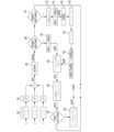
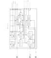
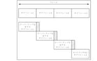
図1は、ウェアラブルデバイス102の一例のシステム図を示す。ウェアラブルデバイスは、患者の皮膚に取り外し可能に取り付けるように構成することができる。ウェアラブルデバイスは再ウェアラブルであり得るか、又はウェアラブルデバイスは使い捨て可能であり得る。ウェアラブルデバイス102は、使い捨て部品110及びエレクトロニクスモジュール120(例えば、再利用可能なエレクトロニクスモジュール)を含む少なくとも2つの部品を含み得る。使い捨て部品110及びエレクトロニクスモジュールの各々は、プリント回路板アセンブリ(PCBA)を備えることができる。エレクトロニクスモジュール120は、コンピューティングプラットフォーム108、プロセッサ111(例えば、マイクロコントローラユニット(MCU))、ワイヤレス通信回路106、ユニバーサルシリアルバス134(USB)、加速度計(ACC)122、メモリ112、LED136、32KHz水晶クロック(X-Tal)126、外部デバイスとの通信接続を開始するために使用し得るユーザボタン140、及びセンサインターフェース116を備えることができる。様々な例において、エレクトロニクスモジュール120は、ジャイロスコープ、身体組成回路、SpO2オキシメトリ回路、並びにECGシグナル、温度シグナル、及び加速度計シグナルを処理するための回路を含み得る。SpO2パルスオキシメトリ回路は、酸素を輸送することができるヘモグロビンに対する酸化ヘモグロビンの割合を計算することによって動脈血の機能的酸素飽和度をモニタリングすることができる。SpO2パルスオキシメトリ回路は、SpO2の連続的非侵襲的測定を提供するように構成することができ、プレチスモグラフ波形を示すことができる。心拍数値はSpO2パルスオキシメトリシグナルから誘導することができる。エレクトロニクスモジュール220はまた、外部メモリへの接続ポート、外部センサへの接続ポート、及びハードウェアアクセラレータも備える。FIG. 1 shows a system diagram of an example
エレクトロニクスモジュール120は、ウェアラブルデバイス102の様々な機能を実装するためのハードウェア構造とソフトウェアフレームワークとを備え得る、特定用途向け集積回路(ASIC)ベースのコンピューティングプラットフォーム108を備え得る。コンピューティングプラットフォーム108は、エレクトロニクスモジュール120のPCBA上に配置することができ、これとインターフェースで連結することができる。使い捨て部品110は、エレクトロニクスモジュール120のPCBAとインターフェースで連結できる。エレクトロニクスモジュール120及び使い捨て部品110は、各々、それぞれの部品、110、120のPCBA上に配置することができるか、又はそれぞれのモジュール、110、120のPCBAから除去することができる追加のモジュールを備えていてもよい。
コンピューティングプラットフォーム108は、様々なセンサ及びウェアラブルデバイス102の部品の組み合わせとインターフェースで連結するように設計された回路を備え得る。例えば、コンピューティングプラットフォーム108は、アナログフロントエンド、ベクトル/デジタルシグナル処理、マイクロプロセッサ及びメモリの組み合わせを、例えば、インジェスティブルイベントマーカーの検出、心電図(ECG)シグナルの検知及びデコード、AC皮膚インピーダンス測定、(例えば、皮膚及び/又は周囲の)温度測定、DC皮膚インピーダンス(例えば、電気皮膚反応(GSR))測定、加速度計測定、及び他の生物学/医療データセンサのためのソフトウェア無線などの、複数の機能を含み得る単一の低電力ASIC/チップで提供できる。
プロセッサ111は中央処理装置(CPU)であり得る。プロセッサ111は、汎用プロセッサ、チップマルチプロセッサ(CMP)、専用プロセッサ、組込みプロセッサ、デジタルシグナルプロセッサ(DSP)、ネットワークプロセッサ、メディアプロセッサ、入力/出力(I/O)プロセッサ、メディアアクセス制御(MAC)プロセッサ、無線ベースバンドプロセッサ、ベクトルコプロセッサ、マイクロプロセッサ、例えば、複数命令セットコンピュータ(CISC)マイクロプロセッサ、縮小命令セットコンピューティング(RISC)マイクロプロセッサ、及び/又は超長命令語(VLIW)マイクロプロセッサ、又は他の処理デバイスとして実装することができる。プロセッサはまた、コントローラ、マイクロコントローラ、特定用途向け集積回路(ASIC)、フィールドプログラマブルゲートアレイ(FPGA)、プログラマブルロジックデバイス(PLD)などにより実装することもできる。
プロセッサ111は、オペレーティングシステム(OS)及び様々なモバイルアプリケーションを実行するように構成することができる。例えば、OSには、Microsoft Windows OSの商品名で一般に知られているオペレーティングシステム、及び任意の他の専用又はオープンソースOSが含まれ得る。モバイルアプリケーションには、例えば、電話アプリ、カメラ(例えば、デジタルカメラ、ビデオカメラ)アプリ、ブラウザアプリ、マルチメディアプレーヤーアプリ、ゲームアプリ、メッセージングアプリ(例えば、電子メール、ショートメッセージ、マルチメディア)、ビューアーアプリなどが含まれ得る。プロセッサ111は、通信インターフェースを通して情報を受信するように配置することができる。通信インターフェースは、ウェアラブルデバイス102を1つ以上のネットワーク及び/又はデバイスに連結することができる、任意の好適なハードウェア、ソフトウェア、又はハードウェアとソフトウェアとの組み合わせを含み得る。
プロセッサ111は、例えば、他の部品の中でも、リアルタイムアプリケーションのための、ARM Cortex(商標)M3プロセッサ、シグナル処理アクセラレータ(例えば、ベクトルコプロセッサ)、例えば、Vector Math Accelerator、プログラムメモリ、データメモリ、シリアルインターフェース、例えば、SPI、汎用非同期送受信機(UART)、2線式マルチマスタシリアルシングルエンドバスインターフェース(I2C)、汎用入力/出力(GPIO)、リアルタイムクロック、アナログ-デジタルコンバータ(ADC)、生体電位シグナル用の利得及び調整回路、発光ダイオード(LED)ドライバーなどを含み得る。プロセッサ111は、アナログセンサのアナログフロントエンドを操作したり、ADCコンバータを用いてセンサからのデジタルデータを受信したりすることによって、センサの各々からのシグナルを受信することができる。プロセッサ111は、データを処理することができ、また結果をメモリ112にデータレコードの形態で保存することができる。様々な例において、プロセッサ111は超長命令語(VLIW)プロセッサ構造を有していてもよい。
ワイヤレス通信回路106は、モバイルチップセット無線周波数(RF)ワイヤレス回路又は単にセル無線であり得る。ワイヤレス通信回路106は低電力モバイルチップセットであってもよく、セルラーネットワーク並びに他のリモートデバイス(例えば、中でも、携帯電話、スマートホン、タブレットコンピュータ、ノートパソコン、ゲートウェイデバイスなどのワイヤレスデバイス)と接続するように構成することができる。ワイヤレス通信回路106は、以下で詳細に記載するように、ワイヤレスシグナルを受信し送信するアンテナ、送信機回路、受信機回路、及び、別の外部ワイヤレスデバイスと接続(リンクを確立)しデータを転送するメカニズムを含むリンクマスタコントローラを備えることができる。リンクマスタコントローラは、外部デバイス、例えば、モバイルデバイスに対する接続を確立することができる。リンクのマスタとして、リンクマスタコントローラは、タイミング制御及び無線周波数制御(チャンネルホッピング)を含む、外部デバイスへのリンクでのデータ伝送の制御を実施することができる。リンクマスタコントローラは、メモリに保存されているデータレコードの数(全データレコードの総数及び各データタイプのレコードの総数)を与える命令で、リモートデバイスにシグナルを送ることができる。ワイヤレス通信回路106は、限定されるものではないが、中でも、Nvidia製のTegra、Qualcomm製のSnapdragon、Texas Instruments製のOMAP、Samsung製のExynos、Apple製のAx、ST-Ericsson製のNovaThor、Intel製のAtom、Freescale Semiconductor製のi.MX、Rockchip製のRK3xxx、AllWinner製のA31をはじめとする、様々な販売会社から入手可能なモバイルチップセットを使用して実装することができる。そのようなモバイルチップセットは、当該技術分野では、とりわけ別名、「モバイル」、「ワイヤレス」、「セルラーフォン」、「セルフォン」、「ハンドフォン(HP)」、「スマートホン」として知られるモバイル電話で用いられる。様々な例において、ウェアラブルデバイス102は有線回路を介して通信することができる。様々な例において、ウェアラブルデバイス102はBluetoothを介して通信することができる。
各接続後、プロセッサ111は、すべてのセンサシグナルを受信し続け、データを処理し、新しいデータレコードをメモリ112に保存することができる。その後の接続の各々に際して、リンクマスタコントローラは、最後の接続以降の新しいデータレコードとともに(例えば、ウェアラブルデバイス102の外部の)リモートデバイスへシグナルを送信することができ、データレコードが正常に送信されたことを確認できる。リンクマスタコントローラは、リモートデバイスがデータレコードを受信できる準備ができたか否かを立証するリモートデバイスからのシグナルを受信することができ、また、どのデータレコードが正常に転送されなかったかを立証するリモートデバイスからシグナルを受信することができる。リンクマスタコントローラは、すでに送信されたデータレコードの送信を繰り返すことを回避することができ、これにより、長期操作のバッテリ消費電力を改善することができ、また、正常に転送されなかったデータレコードを再送することができる。リンクマスタコントローラは、メモリ112から、正常に転送されたデータレコードのすべて又は一部を後の時点で(例えば、メモリ112がいっぱいになった時に)削除することができる。 After each connection,
メモリ112は非一時的メモリであり得、プロセッサ111によって実行される場合に、プロセッサ111及び/又はリモートデバイス上のプロセッサに様々なアルゴリズム及び本明細書中に記載する他の技術革新の機能を実施させることができるマシンで実行可能な命令を含み得る。様々な例において、マシンで実行可能な命令の少なくとも一部はリモートデバイス上のメモリに保存される。
センサインターフェース116は、電極150とバンドパスフィルタ又はチャンネルとの間に配置することができる。センサインターフェース116はアナログフロントエンドを提供することができ、プログラム可能な利得又は固定利得増幅器、プログラム可能なローパスフィルタ、プログラム可能なハイパスフィルタを含んでもよい。センサインターフェース116は、例えば、歪みゲージ測定回路をはじめとするアクティブなシグナル調製回路を含んでもよい。1つのチャンネルは、患者(例えば、ユーザ、対象)の生理学的データに関連する低周波数情報を受信することができ、別のチャンネルは、患者内の電子機器デバイスに関連する高周波数情報を受信することができる。高周波数チャンネルは患者のDCデータを受信することができる。高周波数チャンネルデータは、コンピューティングプラットフォーム108に実装されたデジタルシグナルプロセッサ(DSP)に伝えられ、次に展開及びデコードのためにプロセッサ111に伝えることができるか、又はプロセッサ111に直接伝えることができる。低周波数チャンネルデータは、コンピューティングプラットフォーム108のDSP部分に伝えられ、次にプロセッサ111に伝えることができるか、又はプロセッサ111に直接伝えることができる。DSP部分及びプロセッサ111は、高周波数チャンネル及び低周波数チャンネルからのデータをデコードすることができる。データを次に処理し、送信のために準備することができる。
シグナル処理は、チャンネルから収集された生データに適用される場合もあるし、又は適用されない場合もある。シグナル処理は、実空間、複素数空間、又は極座標空間中で行うことができる。シグナル処理の関数には、中でも、フィルタ、例えば、有限インパルス応答(FIR)及び無限インパルス応答(IIR)、ミキサ、高速フーリエ変換(FFT)、三角関数が含まれる。生データを、単にメモリ112中に保存し、後にダウンストリームで処理してもよい。シグナル処理はプロセッサ111で行ってもよいし、又はコンピューティングプラットフォーム108に組み込むことができるシグナル処理アクセラレータで行ってもよい。ウェアラブルデバイス102上の様々なセンサからの生理学的データをプロセッサ111によって処理することができ、リアルタイム若しくは生データとして送信してもよいし、又は誘導された量若しくはパラメータを送信してもよい。生理学的データは、加速度計データ、ECGデータ、及び他の生理学的データを含み得る。加速度計データは、ECGデータに対して時間的に平行であり得る。 Signal processing may or may not be applied to the raw data collected from the channels. Signal processing can be done in real space, complex number space, or polar space. Signal processing functions include filters such as finite impulse response (FIR) and infinite impulse response (IIR), mixers, fast Fourier transforms (FFT), trigonometric functions, among others. Raw data may simply be stored in
エレクトロニクスモジュール120は、同じであるが、例えば、1つは皮膚の近くに、もう1つは追加のデータを測定するために周囲環境に延在しているなど、異なる位置に配置された2つの温度センサ124を備え得る。温度センサ124は、皮膚、周囲、及び回路基板温度を測定し記録するように構成することができる。温度センサ124を使用して、皮膚と周囲温度センサとの間の熱流束を測定することができる。温度センサ124は、負の温度係数(NTC)又は正の温度係数(PTC)を有するサーミスタデバイスであり得る。温度センサ124は、統合半導体デバイスを使用できる。温度シグナルをプロセッサ111に提供することができ、またプロセッサ111によって処理することができ、ワイヤレス通信回路106の送信機部分による送信のために準備することができる。 The
加速度計122は、リサンプリング周波数補正プロセッサを有する3軸加速度計であり得る。図2に示すように、ウェアラブルデバイスの一例が提示され、ウェアラブルデバイスの埋め込まれた加速度計が加速度計データを測定及び出力し得る際に基づく、関連するX、Y、及びZ軸が示されている。加速度計122は、異なる記録モードを含むことができ、例えば、ウェアラブルデバイス102は、生加速度計X、Y、Zデータのみを記録することができるか、又はウェアラブルデバイス102は、生加速度計X、Y、Zデータ及び通常の加速度計メトリックを記録することができる。
図1に戻ると、加速度計122は、MEMSベースの加速度センサ素子、デジタイザー、及びデジタルインターフェース制御ロジックを含むデジタル加速度計であり得る。加速度計122は、低精度の抵抗器-コンデンサ(RC)オシレータを使用して、デジタイザーサンプリング入力をストローブすることができる。エレクトロニクスモジュール120は、加速度計122からシグナルを受信し、再サンプリングを実施してRCオシレータエラーを相殺する加速度計サンプリング周波数補正プロセッサを備え得る。 Returning to FIG. 1,
加速度計122は、基準クロック(高精度オシレータ)、固定アップサンプルブロック、デジタルフィルタ、プログラム可能なダウンサンプルブロック、及び加速度計からのシグナルのタイミング及び基準クロックの比較に基づいてダウンサンプル係数を選択する制御回路を含むサンプリング周波数補正プロセッサを含み得る。再サンプリング機能は、スライディングウインドウ中の基準クロックに対するアラインメントを保持して、正確なサンプリング速度を得ることができる。時間アルゴリズムはリアルタイム32kHz水晶クロック(X-Tal)126を較正できる。加速度計122サンプリング周波数補正プロセッサは、加速度計シグナルからのデータの各フレームのダウンサンプリング係数を設定することができる。加速度計シグナルのタイミングは、継続的に追跡することができ、ダウンサンプリング係数を選択して、累積タイミングエラーを最小限に抑えることができる。したがって、加速度計122からの加速度計データは、高精度で正確なクロックに整列させることができる。 The
エレクトロニクスモジュール120は、低電力低メモリデータ保存及び転送スキームを採用することができる。例えば、メモリ112内のデータの保存及び転送は、低電力及び低メモリ使用量のために最適化することができる。センサシグナルからの生理学的データは、メモリ112内に、それぞれが型識別子を有するデータレコードとして保存することができる。データレコードは、ワイヤレス通信回路106によってパケットペイロードでリモートデバイスへ転送することができる。データレコードは、可変長で順次保存して、メモリ112内のスペース使用量を最適化することができる。データディレクトリをメモリ112中に提供することができ、これによりメモリ112からの高速レコード読取アクセスを可能にできる。データディレクトリはまた、タイプ別のデータレコードの迅速なカウントを可能にすることもできる。
エレクトロニクスモジュール120は高信頼性完全性データ保存及び転送スキームを採用することができる。例えば、ウェアラブルデバイス102メモリ保存及び転送スキームは、高信頼性データ完全性のために設計することができる。ウェアラブルデバイス102のメモリ112中に保存された各データレコードについて、データレコードの破損を検出するために使用できるエラー検出コードがあり得る。ウェアラブルデバイス102がリモートデバイスへのデータパケット転送に先立ってメモリ112からデータレコードを読み取る場合、エラー検出コードをチェックすることができる。ウェアラブルデバイス102が保存されたデータレコードの破損を検出すると、エラーシグナルをワイヤレス通信回路106によってリモートデバイスに送信することができる。ウェアラブルデバイス102からリモートデバイスへ転送された各パケットは、エラー検出コードを含み得、これはリモートデバイスでパケット破損を検出するために使用できる。
コンピューティングプラットフォーム108のシグナル処理アクセラレータ部分は、高効率シグナル処理タスクを実装するために最適化された計算エンジンを含み得る。シグナル処理機能は、プロセッサ111又は他のマイクロコントローラユニットで実行されるソフトウェアに実装されたソフトウェアベースのアルゴリズムと比較して、10倍以上効率的であり得るロジックでハードコーディングすることができる。効率は、チップサイズの減少、消費電力の減少、及び/又はクロック速度の減少であり得る。シグナル処理機能は、あるレベルのプログラム可能性を維持することができるが、最適化された計算である実行ユニットを利用することができる。例えば、シグナル処理機能は、様々なサイズのデータセットについてFFT計算を可能にすることができるが、プロセッサ111で実行されるソフトウェアよりも著しい効率改善を維持することができる高速フーリエ変換(FFT)-バタフライエンジンを採用することができる。実行ユニットはまた、乗累算ユニット(MAC)であってもよく、これは、共通のDSP機能ブロックであるか、又は浮動小数点計算ユニット(複数可)若しくはFIRフィルタプリミティブなどであり得る。これらの例では、所与の集積回路プロセスの効率は、プロセッサ111上のソフトウェアの効率よりも大きいが専用のハードウェアの効率よりも小さい可能性があるが、限られたリソースと生理学的測定の精度とのバランスをとる点で、はるかに柔軟であり得る。 The signal processing accelerator portion of
シグナル処理アクセラレータは、プロセッサ111とのインターフェースを維持することができる。このインターフェースは、先入れ先出し(FIFO)レジスタ、デュアルポートメモリ、プロセッサ111のダイレクトメモリアクセス(DMA)エンジン、及び/又はレジスタを含んでもよい。インターフェースは、レジスタレベル又はメモリブロックレベルで取り扱われる場合がある競合の認識又は回避のある形態を含み得る。関与するメカニズムは、プロセッサ111及びシグナル処理アクセラレータによってポーリングされ得るレジスタフラグセットを含んでもよく、シグナルへのインタラプトは、優先順位の高いデバイスが自身の活動を完了するまで、読取又は書き込み要求を保持する機能をブロック又は遅延することができる。 A signal processing accelerator may maintain an interface with
使い捨て部品110は、エレクトロニクスモジュール120のPCBAに連結させることができる。使い捨て部品は、インターフェースに関して、モニタリングするもの(人間、動物、マシン、ビルディング等)に取り付けられたセンサ、例えば、皮膚電位(EDA)センサ、GSRセンサ、(例えば、皮膚及び/又は周囲の)温度センサ、身体組成センサ(50Hz)、SpO2/パルスオキシメトリセンサ、歪みゲージセンサ、加速度計、及び他の生物学/医療データセンサを含み得る。コンピューティングプラットフォーム108又はプロセッサ111によって実行される様々なアルゴリズムは、例えば、ステップカウント、ボディアングル、心拍数、心拍数変動性、安静、安静時の心拍数、熱流束、呼吸速度、ストレスレベル、転倒検知、及び他の生理学的メトリックなどのメトリックを生成することができる。
使い捨て部品110はまた、バッテリ160、バッテリを保持するためのクレードル、バッテリホルダ又はハウジング(カバー)、接着剤、及び電極150(例えば、少なくとも2つの電極)も含み得る。電力は、バッテリ160からウェアラブルデバイス102へ提供することができる。バッテリ160は、使い捨て部品110の接着剤の有効寿命にほぼ等しいバッテリ寿命を有する使い捨てのコイン電池であり得る。接着剤はウェアラブルデバイス102を患者の皮膚に付着させることができる。接着剤は、ほとんどの患者に関して3~10日の有効寿命を含み得る。電極150は、ヒドロゲル電極と個別のステンレス鋼電極とを含み得る。ヒドロゲル電極は、患者がデジタルメディスンを摂取したことを示すことができる、高周波の体内電気シグナル(10KHz以上)を検出するために使用することができる。
メモリ112は、揮発性及び不揮発性メモリの両方を含む、データを保存することができる任意のマシン可読又はコンピュータ可読媒体を含み得る。例えば、メモリ112は、読み出し専用メモリ(ROM)、ランダムアクセスメモリ(RAM)、ダイナミックRAM(DRAM)、ダブルデータレートDRAM(DDR-RAM)、シンクロナスDRAM(SDRAM)、スタティックRAM(SRAM)、プログラマブルROM(PROM)、消去可能なプログラマブルROM(EPROM)、電気的に消去可能なプログラマブルROM(EEPROM)、フラッシュメモリ(例えば、NOR又はNANDフラッシュメモリ)、コンテントアドレッサブルメモリ(CAM)、ポリマーメモリ(例えば、強誘電性ポリマーメモリ)、相変化メモリ(例えば、オボニックメモリ)、強誘電体メモリ、シリコン酸化物窒化物酸化物シリコン(SONOS)メモリ、ディスクメモリ(例えば、フロッピディスク、ハードドライブ、光ディスク、磁気ディスク)、又はカード(例えば、磁気カード、光カード)、又は情報を保存するために適した任意の他の種類のメディアを含み得る。
ステップカウント step count
ウェアラブルデバイス102は、使い捨て部品110(例えば、接着性ストリップ)の接着剤を用いて患者にウェアラブルデバイスを取り付けることによって患者に着用させることができる。患者が移動すると、加速度計112は、加速度計122が経験する加速力に基づいた加速度計シグナルを提供することができる。加速の変動は、患者の動作/活動を示すことができる。加速度計シグナルは、ウェアラブルデバイス102によって加速度計データに変換することができる。
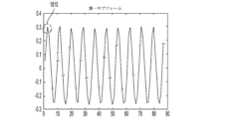
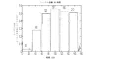
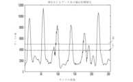
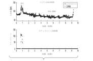
歩行は、加速度計シグナルから得られる加速度計データ及び/又は自己相関データにおいて強力なピークと解釈され得る周期的/規則的動作であり得る。加速度計データを分析し、使用して、患者が歩いたステップカウント(例えば、ステップカウント)を計算することができる。例えば、図3に示すように、各軸X、Y、Zの個々にトレースを含み得る加速度計データ302が提供される。加速度計データ302は、ウェアラブルデバイス102を着用した患者が24歩歩いた加速データの14秒ブロックの加速データを含む。加速度計データ302が閾値を超える回数の計数を用いて、加速度計データ302からのステップカウントの生理学的メトリックを決定することができる。加速度計データ302から測定されるステップカウントは、14秒の期間で24ステップを測定することに基づいて103ステップ/分である。 Walking can be a periodic/regular movement that can be interpreted as strong peaks in the accelerometer data and/or autocorrelation data obtained from the accelerometer signal. Accelerometer data can be analyzed and used to calculate the step count (eg, step count) taken by the patient. For example, as shown in FIG. 3, accelerometer data 302 is provided, which may include traces for each axis X, Y, Z individually. Accelerometer data 302 includes 14-second blocks of acceleration data taken by a patient wearing
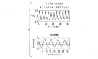
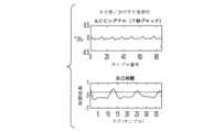
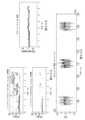
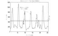
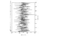
ウェアラブルデバイス102は、移動が困難(例えば、高齢の患者)又はゆっくりとしたペースで歩行する患者が使用することができる。本明細書中で使用する場合、「緩徐な歩行」は、15~80歩/分の範囲内のステップレートを指し、普通の歩行は、80~150歩/分の範囲内のステップレートを指す。以前の比較アルゴリズムは、足が遅い(例えば、足を引きずる、及び/若しくはゆっくり動く)又は運転しているかもしれない患者の加速度計データからステップカウントを正確に計算することはできない可能性がある。例えば、加速度計データは普通の歩行ステップに見えない場合があり、また、加速度計データはステップカウントを計算するために容易に分析できない場合がある。例えば、図4Aの上段は、100ステップ/分(例えば、普通の歩行)の移動速度での加速度計データ例を示し、図4Cの上段は、50ステップ/分(例えば、緩徐な歩行)の移動速度での加速度計データ例を示す。 The
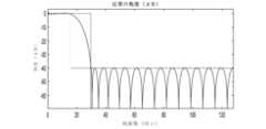
比較アルゴリズムは、自己相関データ(例えば、図4A~図4Eで破線によって示される閾値)におけるレベルクロッシングの計数にのみ依存し得る。図4Aの下段に示すように、普通の歩行によって生じる自己相関データの閾値のクロッシングの計数の結果、レベルクロッシングのみに基づいて正確なステップカウント(例えば、+/-10%を超える)が得られる可能性がある。しかしながら、図4Cの下段に示すように、緩徐な歩行によって得られた自己相関データのレベルクロッシングの計数の結果、レベルクロッシングのみに基づくと不正確なステップカウントが得られる可能性がある。 The comparison algorithm may rely only on counting level crossings in the autocorrelation data (eg, thresholds indicated by dashed lines in FIGS. 4A-4E). As shown in the bottom row of FIG. 4A, counting the threshold crossings of the autocorrelation data caused by normal walking results in an accurate step count (eg, greater than +/-10%) based on level crossings alone. there is a possibility. However, counting level crossings of autocorrelation data obtained by slow walking, as shown in the lower part of FIG. 4C, can result in inaccurate step counts based on level crossings alone.
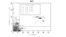
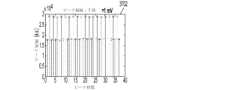
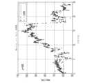
図4Eを参照すると、ステップカウントデータ点のプロットが提供され、各点は、比較アルゴリズムから分析された図4Eで特定される各活動のみからなる加速度計データの7秒ブロックを表す。普通の歩行100歩/分のデータを4分間にわたってサンプリングし、ステップカウントについて400ステップの期待値であった;緩徐な歩行50歩/分のデータを4分にわたってサンプリングし、ステップカウントについて200の期待値であった;低速シャフリング60歩/分のデータを4分間にわたってサンプリングし、ステップカウントについて240の期待値であった;中速シャフリング80歩/分のデータを4分間にわたってサンプリングし、ステップカウントについて320の期待値であった;ドライブデータ(例えば、0歩/分)を様々な時間にわたってサンプリングし、ステップカウントについて0の期待値であった。 Referring to FIG. 4E, a plot of step count data points is provided, each point representing a 7 second block of accelerometer data consisting solely of each activity identified in FIG. 4E analyzed from the comparison algorithm. Data of 100 steps/min of normal walking were sampled over 4 min with an expected value of 400 steps for step count; Data of 50 steps/min of slow walking were sampled over 4 min with an expected value of 200 for step count slow shuffling 60 steps/min data sampled over 4 min, expected value of 240 for step count; medium shuffling 80 steps/min data sampled over 4 min, step There was an expected value of 320 for count; the drive data (eg, 0 steps/min) were sampled over various times and an expected value of 0 for step count.
緩徐な歩行についての不正確なステップカウントに加えて、図4B、図4E、及び図5に示すように、ドライブは誤ったステップカウントを引き起こす可能性がある。さらに、表1に示すように、比較アルゴリズムを含む比較歩数計は、不正確なステップカウントを提供する(例えば、運転中に誤ったステップカウントを検出する)可能性がある。さらに、比較歩数計は加速度計データを連続して(例えば、不連続的にではなく)受信する。 In addition to inaccurate step counting for slow walking, driving can cause erroneous step counting, as shown in FIGS. 4B, 4E, and 5. FIG. Furthermore, as shown in Table 1, a comparative pedometer that includes a comparative algorithm may provide inaccurate step counts (eg, detect erroneous step counts while driving). Further, the comparative pedometer receives accelerometer data continuously (eg, not discontinuously).

したがって、緩徐な歩行中に、ウェアラブルデバイス102によって生成される加速度計データを含む不連続データにおいてステップカウントを不正確にカウントするステップカウントアルゴリズムが提供される。ステップカウントアルゴリズムは、少なくとも1000歩にわたって測定して±3パーセントの平均誤差で検出された生理学的データを使用して80~150歩/分のステップレート範囲のステップカウントを決定することができる。さらに、ステップカウントアルゴリズムは、ドライブ中又は他のタイプの動作中の誤ったステップカウントを、防止できなかったとしても制限することができる。 Accordingly, a step counting algorithm is provided that incorrectly counts steps in discrete data, including accelerometer data, generated by
ステップカウントアルゴリズムは、不連続データから連続的なステップレートを推定することによって、メモリと電力を節約することができる。例えば、毎分、ウェアラブルデバイスは、加速度計データの14秒フレームを収集し、このフレーム上でステップレートを計算し、ステップレートを内挿して、1分のステップ数を誘導することができる。精度を最適化するために、アルゴリズムは14秒フレームの境界でのハーフステップを考慮することができる。 A step count algorithm can save memory and power by estimating the continuous step rate from discrete data. For example, every minute the wearable device can collect a 14 second frame of accelerometer data, calculate the step rate on this frame, and interpolate the step rate to derive the number of steps per minute. To optimize accuracy, the algorithm can consider half-steps at 14 second frame boundaries.
加えて、ウェアラブルデバイス102は、活動レベルに基づいてデータを分類するように構成することができる。例えば、ウェアラブルデバイス102は、浴室から台所までの簡単な歩行などの思い付きのウォーキング(例えば、第1の活動レベルよりも低い第2の活動レベル)と比較して、より高速で、より明確なステップ(例えば、第1の活動レベル)を含む「意図的なウォーキング」を区別することができる。ウォーキングのタイプは、加速度計データに基づいたステップカウントアルゴリズムによって区別することができる。 Additionally,
ステップカウントアルゴリズムは加速度計データを受信することができ、制御回路によって実行するためにウェアラブルデバイス102及びリモートデバイスにわたって分配することができる。例えば、ステップカウントアルゴリズムは、メモリ112に保存することができ、プロセッサ111によって利用されて、加速度計122から受信した加速度計データを、生理学的メトリック、例えば、ステップカウントなどに変換することができる。 The step counting algorithm can receive accelerometer data and can be distributed across
本明細書においてアルゴリズムの構成を記載する目的で、加速度計値は「g」の単位で解釈され、ここで、「g」は、徳野別段の記載がない限り、地球の重力による加速度(約9.8m/s2)である。性能の最適化のために、設計の実装は、生の加速度計カウントで操作することができる。For the purposes of describing the construction of algorithms herein, accelerometer values are interpreted in units of "g", where "g" is the acceleration due to Earth's gravity (approximately 9 .8 m/s2 ). For performance optimization, the design implementation can operate on raw accelerometer counts.
ステップカウントアルゴリズムは、ソースコード内のデフォルト値に設定することができるが、ステップカウントアルゴリズムの全体的又は部分的再設計無しで(ソフトウェアの完全再コンパイルで)調節することができる、表2に記載するような固定パラメータを含み得る。 The step count algorithm can be set to default values in the source code, but can be adjusted without a complete or partial redesign of the step count algorithm (with a full recompilation of the software), listed in Table 2. It may contain fixed parameters such as

ステップカウントアルゴリズムは、表3に記載するようなプログラム可能なパラメータを含み得る。ステップカウントアルゴリズムは、デフォルト値に設定することができ、製造中及び/又はワイヤレス/優先インターフェースを介した使用中に再構成することができる。各々のプログラム可能なパラメータは、すべての状態遷移及びウェアラブルデバイス102からの電力の完全な除去(例えば、バッテリの切断)によりその設定値を維持することができる。 The step count algorithm may include programmable parameters as listed in Table 3. The step count algorithm can be set to default values and reconfigured during manufacture and/or during use via the wireless/priority interface. Each programmable parameter can maintain its set value through all state transitions and complete removal of power from the wearable device 102 (eg, disconnecting the battery).

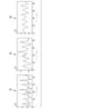
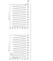
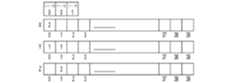
ステップカウントアルゴリズムは、選択された周波数でサンプリングされた選択された時間ウインドウ中の加速度計データを処理することができる。14秒の時間ウインドウと12.5GhZの選択された周波数の例で、175のサンプルがウインドウ。ステップカウントは、図6で示される単一のブロックを含むサンプルバッファーで誘導することができるか、又はサンプルバッファーは、図7A~図7Bで示されるように、2つのブロック、ピリオド1(P1)及びピリオド2(P2)に分割できる。サンプルの数が奇数である例では、各ピリオドが等しくなるように1つのポイントを除外してもよい。サンプルの数が175である例では、各ピリオドが等しくなるように175番目のサンプルを除外できる。 A step count algorithm can process accelerometer data during a selected time window sampled at a selected frequency. A window of 175 samples with an example time window of 14 seconds and a selected frequency of 12.5 GhZ. The step count can be derived with a sample buffer containing a single block as shown in FIG. 6, or the sample buffer can be divided into two blocks, period 1 (P1), as shown in FIGS. 7A-7B. and period 2 (P2). In instances where the number of samples is odd, one point may be left out so that each period is equal. In the example where the number of samples is 175, the 175th sample can be omitted so that each period is equal.
ステップカウントアルゴリズムは、本明細書中で記載する評価、計算、及び変換を実施することができ、表4で記載するような加速度計レコード(ACR)を生成することができる。ACRは、所望により測定期間ごとに1回又はそれ以上の回数で作製することができる。 A step count algorithm can perform the evaluations, calculations, and conversions described herein, and can generate an accelerometer record (ACR) as described in Table 4. The ACR can be made one or more times per measurement period if desired.

加速度計データは、式1に示すように用いられるの感度によって定義される、固定変換値Gを用いて「g」(又は加速度の二乗の尺度である場合はg2)に正規化することができる。デフォルトは2G感度であり得る。Accelerometer data can be normalized to 'g' (or g2 if it is a squared measure of acceleration) using a fixed transformation value G, defined by the sensitivity of the used as shown in

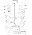
図6は、患者の緩徐な歩行中のステップカウントを正確に決定できるステップカウントアルゴリズムのフローチャートの例を示す。図示されているように、x軸加速度計データ、y軸加速度計データ、及びz軸加速度計データ、まとめて加速度計データを、ステップカウントアルゴリズムによって処理することができる。 FIG. 6 shows an example flow chart of a step count algorithm that can accurately determine the step count during slow walking of a patient. As shown, x-axis accelerometer data, y-axis accelerometer data, and z-axis accelerometer data, collectively, can be processed by a step count algorithm.
加速度計データの各軸における生加速データ(例えば、ベクトル)は、ボックスカーフィルタを使用したステップカウントアルゴリズムによって処理して、式2、602に従ってノイズを軽減し、シグナルの高周波数成分を除去することができる。 The raw acceleration data (e.g., vectors) in each axis of the accelerometer data are processed by a step counting algorithm using a boxcar filter to reduce noise and remove high frequency components of the signal according to

デフォルトパラメータ値AccFs=12.5Hz及びM=2の例では、3.125Hzより低い周波数成分を正確に再現できる。 In the example of default parameter values AccFs=12.5 Hz and M=2, frequency components below 3.125 Hz can be reproduced accurately.
12.5Hzでサンプリングされた加速度計データは、生加速度データに適用されるタップフィルタ、例えば、2-タップフィルタ等を有し得る。フィルタ中のタップが多いほど、加速度計データがより平均化される。タップフィルタは、忠実に表すことができる高周波数を決定することができる。様々な長さのタップフィルタを生加速度データに適用して、活動(例えば、ジムのエクササイズ)中のステップカウントの感度を特徴づけることができる。生加速度データに適用されるサンプリング速度及びデジタルフィルタ(例えば、タップフィルタ)は、所望の用途に対して構成することができる。様々な例において、ウェアラブルデバイス102のハードウェアは異なるサンプリング速度(例えば、より高いサンプリング速度)をサポートできる。 Accelerometer data sampled at 12.5 Hz may have a tap filter applied to the raw acceleration data, such as a 2-tap filter. The more taps in the filter, the more the accelerometer data is averaged. A tap filter can determine the high frequencies that can be faithfully represented. Various length tap filters can be applied to the raw acceleration data to characterize the sensitivity of step counts during activity (eg, gym exercise). The sampling rate and digital filters (eg, tap filters) applied to the raw acceleration data can be configured for the desired application. In various examples, the hardware of
加速度計データの各軸における加速データのポストボックスカーフィルタリングは、式3、604に示すような加速度計データの各軸からの二乗L2ノルムを計算することによって全加速(totAcc、Acctotal,i)に変換することができる。Post-boxcar filtering of the acceleration data in each axis of the accelerometer data is the total acceleration (totAcc, Acctotal,i ) by computing the squared L2 norm from each axis of the accelerometer data as shown in Equation 3,604: can be converted to

ステップカウントアルゴリズムは、計算の簡略化としてL2ノルムの代わりに二乗L2ノルムを利用することができる。式3中のスケーリング係数(例えば、2で除算)は、メモリ中のバッファーのオーバーフロー/飽和を防止することができる。全加速(例えば、totActThresh、totActThreshLo)に関連して閾値を決定及び/又はプログラミングする場合、スケーリング係数を考慮することができる。 The step count algorithm can utilize the squared L2 norm instead of the L2 norm as a computational simplification. The scaling factor (eg, divide by 2) in
全加速データのトータル活動(totActivity)は、式4、4606に示すように全加速データの標準偏差(std(totAcc))をとることによって計算することができる。 The total activity of all acceleration data (totActivity) can be calculated by taking the standard deviation of all acceleration data (std(totAcc)) as shown in

トータル活動は、加速度計データの2ブロックを有する例においてブロックP1及びP2について独立して計算することができ、その結果、図7A~図7Bに示すように2つの浮動小数点値が得られる。 Total activity can be calculated independently for blocks P1 and P2 in an example with two blocks of accelerometer data, resulting in two floating point values as shown in FIGS. 7A-7B.
図6に戻ると、トータル活動は、加速度計データのブロックが有効なステップ活動608を含むか否かを評価するためにステップカウントアルゴリズムによって使用され得る。例えば、ステップカウントアルゴリズムは、トータル活動データが活動閾値を満たす若しくは超えるか否かを評価することができる。トータル活動が活動閾値を満たすか又は超える場合、ステップカウントアルゴリズムはステップ624に進み、加速度計データを平均調節し、ステップカウントについて加速データを評価する。 Returning to FIG. 6, the total activity can be used by the step count algorithm to evaluate whether a block of accelerometer data contains
しかしながら、トータル活動が活動閾値を満たさないか又は超えない場合、ステップカウントアルゴリズムは加速度計データが強化されるべきか否かを評価することができる610。例えば、ステップカウントアルゴリズムは、トータル活動が下限活動閾値を満たすか又は超えるか否かを評価することができる。トータル活動が下限活動閾値を満たさないか又は超えない場合、加速度計データは有効なステップ活動を含まないと判断することができ、加速度計データのブロックにステップはカウントされない。 However, if the total activity does not meet or exceed the activity threshold, the step count algorithm can evaluate 610 whether the accelerometer data should be enhanced. For example, a step count algorithm can evaluate whether total activity meets or exceeds a lower activity threshold. If the total activity does not meet or exceed the lower activity threshold, it can be determined that the accelerometer data does not contain valid step activity and no steps are counted in the block of accelerometer data.
しかしながら、トータル活動が下限活動閾値(例えば、低振幅活動の測定値)を満たすか又は超える場合、加速度計データのブロックを強化することができる612-622。例えば、全加速度計データを強化することができる。下限活動閾値は、加速度計データ中の真のステップ(例えば、緩徐な歩行)と誤ったステップ(例えば、ドライブ)とのさらなる区別を可能にできる。 However, if the total activity meets or exceeds a lower activity threshold (eg, a measure of low-amplitude activity), the block of accelerometer data can be enhanced 612-622. For example, full accelerometer data can be enhanced. A lower activity threshold can allow further discrimination between true steps (eg, slow walking) and false steps (eg, driving) in accelerometer data.
加速度計データ強化は、トータル活動及び、様々な例では、エネルギー消費量に基づいて実施することができる。図7A~図7Bに示すように2ブロックの加速度計データを含む様々な例において、強化は、ブロックP1及びP2について独立して実施することができる。加速度計データ強化により、加速度計データの周期性を増強することができ、ここで、真のステップにより、この強化に基づいて誤ったステップから区別できる追加のアーティファクトが導入された可能性がある。 Accelerometer data enrichment can be implemented based on total activity and, in various examples, energy expenditure. In various examples involving two blocks of accelerometer data as shown in FIGS. 7A-7B, enhancement can be performed independently for blocks P1 and P2. Accelerometer data enhancement can enhance the periodicity of the accelerometer data, where true steps may have introduced additional artifacts that can be distinguished from false steps based on this enhancement.
図6に戻ると、より低いトータル活動閾値は、評価された加速度計データのブロックに基づいて調節することができる612。その後、加速データを式6で示すようなさらなる計算のために調節することができ、それによって平均調節された加速データ(inpZM0)を得る614。Returning to FIG. 6, the lower total activity threshold can be adjusted 612 based on blocks of evaluated accelerometer data. The acceleration data can then be adjusted for further calculations as shown in

平均調節は、加速度計データの各ブロックに対して独立して行うことができる(例えば、図7A~図7Bに示すP1及びP2)。平均調節された加速度計データの絶対値を計算することができる616。 Average adjustments can be made independently for each block of accelerometer data (eg, P1 and P2 shown in FIGS. 7A-7B). An absolute value of the average adjusted accelerometer data can be calculated 616 .
絶対加速度計データはローパスフィルタ(LPF)により処理することができる。すなわち、絶対値は、式7に示すようなエンベロープ検出の手段として5点移動平均フィルタによって決定することができる618。 Absolute accelerometer data can be processed by a low pass filter (LPF). That is, the absolute value can be determined 618 by a 5-point moving average filter as a means of envelope detection as shown in

ローパスフィルタリングされた加速度計データを次いで、ハイパスフィルタ(HPF)によって処理することができる620。例えば、式8に示されるように、4次非再帰的ハイパスフィルタを加速度計データに関して利用して、ドリフトを除去することができる。 The low pass filtered accelerometer data can then be processed 620 by a high pass filter (HPF). For example, a fourth-order non-recursive high-pass filter can be used on the accelerometer data to remove drift, as shown in

ハイパスフィルタリングされた加速度計データは、スケーリングすることができ4622、自己相関の計算のための入力として利用することができる。 The high-pass filtered accelerometer data can be scaled 4622 and used as input for autocorrelation calculations.
図8は、歩いたかどうか、又は加速度計データが他の活動を示すものであるか否かを判定するための加速度計データの強化の例を示す。すなわち、加速度計からの生加速度データ802は、絶対値フィルタ及びローパスフィルタ(例えば、エンベロープ検出)を介した生加速度データ802の処理を行うことによって処理済み加速度計データ804に変換することができる。処理済み加速度計データ804は、ハイパスフィルタ(例えば、ドリフト除去)、平均正規化、及び平滑化など、加速度計データ804を処理することによって、強化された加速度計データ806にさらに変換することができる。図8に示すステップは、任意の順序で実施することができる。その後、ステップカウントアルゴリズムは、強化されたシグナルから特徴を抽出することができる。 FIG. 8 shows an example of enrichment of accelerometer data to determine whether a walk has been performed or whether the accelerometer data is indicative of other activity. That is,
図6に戻ると、図示するように、624(inpZM)で平均調節された加速度計データ又は622(inpZM)からシグナル強化データを、自己相関データ(例えば、AC、aCorr)に変換することができる626。ラグtにおける自己相関データを式9に記載する。計算される自己相関のラグ数tは、表2に記載するようにパラメータACC_AC_LIMによって支配され得る。 Returning to FIG. 6, mean-adjusted accelerometer data at 624 (inpZM) or signal enhancement data from 622 (inpZM) can be converted to autocorrelation data (e.g., AC, aCorr) as shown. 626. The autocorrelation data at lag t are given in

加速データの2ブロックを含む様々な例において、自己相関は各ブロック(例えば、図7A~図7BのブロックP1及びP2)について独立して計算することができる。入力の平均調節及び出力の正規化は、この量を記載するために自己相関という語を使用できるが、AC(t)がラグtにおける自己共分散を表すことを暗示し得る。 In various examples involving two blocks of acceleration data, the autocorrelation can be calculated independently for each block (eg, blocks P1 and P2 in FIGS. 7A-7B). Input mean adjustment and output normalization may use the term autocorrelation to describe this quantity, but may imply that AC(t) represents the autocovariance at lag t.
ステップカウントアルゴリズムは自己相関データにおけるレベルクロッシング(numLC)の数を計算することができる628。レベルクロッシングとは、データ中のシグナルがレベルクロッシング閾値を超える時である。自己相関データの上向き及び下向きレベルクロッシングは独立してカウントすることができる。自己相関データにおけるレベルクロッシングは、図9に示された状態マシンに従って決定することができる。レベルクロッシングを使用して、加速データのブロックが有効なステップ活動を含むか否かを判定することができる630。例えば、ステップカウントアルゴリズムは、レベルクロッシングの数がレベルクロッシング閾値を満たすか又は超えるかを評価することができる(numLCThresh)。加速データにおけるレベルクロッシングの数がレベルクロッシング閾値を満たさないか又は超えない場合、加速度計データは有効なステップ活動を有さないと判定することができ、ステップはカウントされない。 A step count algorithm can calculate 628 the number of level crossings (numLC) in the autocorrelation data. A level crossing is when the signal in the data exceeds the level crossing threshold. Upward and downward level crossings of the autocorrelation data can be counted independently. Level crossings in the autocorrelation data can be determined according to the state machine shown in FIG. Level crossings can be used to determine 630 whether a block of acceleration data contains a valid step activity. For example, a step count algorithm can evaluate whether the number of level crossings meets or exceeds the level crossing threshold (numLCThresh). If the number of level crossings in the acceleration data does not meet or exceed the level crossing threshold, it can be determined that the accelerometer data does not have valid step activity and the steps are not counted.
レベルクロッシングの数がレベルクロッシング閾値を満たすか又は超える場合、レベルクロッシングの数(numZC)は、4624(inpZM)で平均調節された加速度計データ又は4622からのシグナル強化データ(inpZM)でカウントされる632。様々な例では、ステップ632において、レベルクロッシングはゼロクロッシングであり得る(例えば、閾値は0である)又はレベルクロッシングの数はゼロクロッシングとは異なり得る(例えば、閾値はゼロでない数である)。ゼロクロッシングは、データ中のシグナルの符号が変わるときである(例えば、プラスがマイナスになる、又はその逆)。有効なステップ活動を含むとみなされる加速データにおいて、ステップカウントアルゴリズムは、平均調節された加速データ(inpZM)におけるレベルクロッシングの総数に基づいてステップの数を計算することができる。加速度計データ(inpZM)におけるレベルクロッシングは、図9に示す状態マシンに従って決定することができる。上向き及び下向きレベルクロッシングは、図9の状態マシンによって示されるように独立してカウントすることができ、したがって、総ステップカウントを2で割って、実際のステップカウントを決定することができる。例えば、患者の各ステップは、彼/彼女の足を物理的に持ち上げること(下向きクロッシングを生成する)、続いて彼/彼女の足を地面におろすこと(上向きクロッシングを生成する)を含む。したがって、上向き/下向きクロッシング対は1ステップを構成する。 If the number of level crossings meets or exceeds the level crossing threshold, the number of level crossings (numZC) is counted with the average adjusted accelerometer data from 4624 (inpZM) or the signal enhancement data from 4622 (inpZM). 632. In various examples, at
ステップカウントアルゴリズムは、加速度計レコード(ACR)として、加速度計データ由来の出力値(例えば、生理学的メトリック)及び生加速度データ自体を含む出力データを作成することができる。ACRは、本明細書中の表4に示すように構成することができる。ACRは、ウェアラブルデバイス102(例えば、オンボードフラッシュメモリ)及び/又はリモートデバイスのメモリ112中に保存することができる。 The step count algorithm can produce output data as an accelerometer record (ACR), including output values derived from the accelerometer data (eg, physiological metrics) and the raw acceleration data itself. The ACR can be configured as shown in Table 4 herein. The ACR can be stored in the wearable device 102 (eg, on-board flash memory) and/or
図7A~図7Bを参照すると、軸(X、Y、Z)の各々における加速データの平均は、ステップカウントアルゴリズムによって計算することができ、平均加速データは、式10に従って浮動小数点における出力値として報告することができる。平均加速データは、ボディアングルアルゴリズムに対する入力として使用することができ、標準偏差メトリックを計算するためにも使用できる。これらのメトリックは、加速度計データの測定期間ごとに1回だけ計算することができる。 Referring to FIGS. 7A-7B, the average acceleration data in each of the axes (X, Y, Z) can be calculated by a step-count algorithm, and the average acceleration data is expressed as an output value in floating point according to

軸(X、Y、Z)の各々における加速データの標準偏差は、ステップカウントアルゴリズムによって計算することができ、式11で示すように浮動小数点における出力メトリックとして報告することができる。加速データの標準偏差は、加速度計データのP1及びP2ブロックの両方の測定期間につき1回計算することができる。 The standard deviation of the acceleration data in each of the axes (X, Y, Z) can be calculated by a step count algorithm and reported as an output metric in floating point as shown in

エネルギー消費量(EE)は、式12に従って、全加速ベクトルにおけるすべての負の値の絶対値の合計としてステップカウントアルゴリズムによって計算することができる。EEは、ブロックP1及びP2について独立して計算することができ、その結果、2つの浮動小数点値が得られる。EEを使用して、ブロックが有効なステップ活動を含むか否かを判定することができ、また加速度計データのシグナル強化を行うべきか否かも判定することができる。 Energy expenditure (EE) can be calculated by a step counting algorithm as the sum of the absolute values of all negative values in all acceleration vectors according to

図7A~図7Bに示すように、ブロックP1及びP2からの全加速、トータル活動、エネルギー消費量、及び自己相関情報を組み合わせて、測定期間ごとに単一ステップカウント数(UINT16値)を得ることができる。ステップカウントアルゴリズムは以下のステップを含み得る:(i)ブロックが中~高振幅又は低振幅活動ブロックとして適格であるか否かを判定するステップ、(ii)低振幅活動ブロックに対してシグナル強化を実施するステップ、(iii)ブロックが有効なステップ活動を含むか否かを判定するステップ、及び(iv)有効ブロックにおけるステップの数をカウントするステップ。ブロックP1及びP2からのステップカウントを単純に合計して、所与の測定期間内のステップの数を決定する。ブロックP1及びP2について独立して計算することで、ユーザのステップカウントを追跡する際により繊細な精度が可能になる。 Combining total acceleration, total activity, energy expenditure, and autocorrelation information from blocks P1 and P2 to obtain a single step count (UINT16 values) for each measurement period, as shown in FIGS. 7A-7B. can be done. The step counting algorithm may include the following steps: (i) determining whether a block qualifies as a medium-to-high amplitude or low amplitude activity block; (ii) applying signal enhancement to low amplitude activity block; (iii) determining whether the block contains valid step activities; and (iv) counting the number of steps in the valid block. Simply sum the step counts from blocks P1 and P2 to determine the number of steps in a given measurement period. Calculating independently for blocks P1 and P2 allows finer precision in tracking the user's step count.
ブロック(P1又はP2)は、以下の条件が満たされた場合に有効なステップ活動を有するとされる:(i)ブロックにおけるトータル活動が閾値「加速度計トータル活動低閾値」を越える、及び(ii)自己相関のレベルクロッシングの数が閾値「加速度計Num Crossing」を越える。 A block (P1 or P2) is said to have valid step activity if the following conditions are met: (i) the total activity in the block exceeds the threshold "accelerometer total activity low threshold", and (ii) ) The number of autocorrelation level crossings exceeds the threshold "Accelerometer Num Crossing".
上述の条件を満たすブロックについて、ステップの数は、全加速データのレベルクロッシングの総数として計算される。ブロックP1及びP2からのステップカウントを合計して、測定期間における総ステップの数を得る。この数を次に適切にスケーリングして、調節されたステップカウント(すなわち、AStepCount)を決定し、これは1分当たりのステップのおよその尺度である。調節されたステップカウントを、ウェアラブルデバイス及び/又はリモートデバイスに実装されたアルゴリズムへの入力として使用することができる。 For blocks satisfying the above conditions, the number of steps is calculated as the total number of level crossings of all acceleration data. Sum the step counts from blocks P1 and P2 to get the total number of steps in the measurement period. This number is then scaled appropriately to determine the adjusted step count (ie, AStepCount), which is an approximate measure of steps per minute. The adjusted step count can be used as an input to algorithms implemented in the wearable device and/or remote device.
ウェアラブルデバイス102は、プログラム可能なパラメータであり得る加速度計区間及び/又は加速度計期間パラメータに従って加速度計データの取得を開始し停止するスケジューラ(例えば、ステップカウントアルゴリズムの外部のソフトウェアモジュール)を含み得る。加速度計は、加速度計期間パラメータセットの長さについて固定されたサンプリング速度(例えば、12.5Hz)でデータを取得できる。
様々な例において、ステップカウントアルゴリズムは、さらなる評価、例えば、最小及び/又は最大値、検出されたステップ間の時間間隔、及び検出されたステップ評価間の振幅変動などを含み得る。ステップカウントアルゴリズムは、以下の任意選択的特徴の少なくとも1つを使用することができ、全加速に組み合わせる代わりに各軸を別に処理することができ、基準ベクトルを使用して、どの軸(1つ)/軸(複数)を使用するかを決定する前にパッチの向きを決定することができ、またより多くの生理学的データに基づいて閾値を調製することができ、2つの軸からのデータを結合できる。ステップカウントアルゴリズムは、少なくとも1000ステップにわたって測定して、普通の歩行(80~150歩/分)については±3%の精度であり得、緩徐な歩行(15~80歩/分)については±10%の精度であり得る。様々な例において、ステップカウントアルゴリズムは、少なくとも1000ステップにわたって測定して、緩徐な歩行(15~80歩/分)については±5%の精度であり得る。 In various examples, the step count algorithm may include additional evaluations, such as minimum and/or maximum values, time intervals between detected steps, and amplitude variations between detected step evaluations. The step counting algorithm can use at least one of the following optional features, can treat each axis separately instead of combining them into a total acceleration, and use a reference vector to determine which axis (one )/axis to be used, and the threshold can be adjusted based on more physiological data, allowing the data from the two axes to be can be combined. The step counting algorithm measures over at least 1000 steps and can be accurate to ±3% for moderate walking (80-150 steps/min) and ±10% for slow walking (15-80 steps/min). % accuracy. In various examples, the step counting algorithm can measure over at least 1000 steps and be ±5% accurate for slow walking (15-80 steps/min).
図10A~図10Eを参照して、ステップカウントアルゴリズムは、比較アルゴリズムよりも正確なステップカウントを提供することができる。図10A~図10E中の破線は活動閾値を表す。図10Cの緩徐な歩行例で示すように、ステップカウントアルゴリズムは、緩徐な歩行によって生じる自己相関データにおけるレベルクロッシングがより正確なステップカウントをもたらすことができるようにデータを強化している。 Referring to Figures 10A-10E, the step count algorithm can provide a more accurate step count than the comparison algorithm. The dashed lines in FIGS. 10A-10E represent activity thresholds. As shown in the slow walking example of FIG. 10C, the step counting algorithm enhances the data so that level crossings in the autocorrelation data caused by slow walking can result in more accurate step counting.
図10Eは、普通の歩行、緩徐な歩行、低速シャフリング、及びドライブからの加速度計データから比較アルゴリズム及びステップカウントアルゴリズムによって決定されるステップカウント値を示す。普通の歩行100歩/分のデータを4分間にわたってサンプリングし、ステップカウントについて400ステップの期待値であった;緩徐な歩行50歩/分のデータを4分にわたってサンプリングし、ステップカウントについて200の期待値であった;低速シャフリング60歩/分のデータを4分間にわたってサンプリングし、ステップカウントについて240の期待値であった;中速シャフリング80歩/分のデータを4分間にわたってサンプリングし、ステップカウントについて320の期待値であった;ドライブデータ(例えば、0歩/分)を様々な時間にわたってサンプリングし、ステップカウントについて0の期待値であった。 FIG. 10E shows step count values determined by the comparison and step count algorithms from accelerometer data from normal walking, slow walking, slow shuffling, and driving. Data of 100 steps/min of normal walking were sampled over 4 min with an expected value of 400 steps for step count; Data of 50 steps/min of slow walking were sampled over 4 min with an expected value of 200 for step count slow shuffling 60 steps/min data sampled over 4 min, expected value of 240 for step count; medium shuffling 80 steps/min data sampled over 4 min, step There was an expected value of 320 for count; the drive data (eg, 0 steps/min) were sampled over various times and an expected value of 0 for step count.
図10Eはステップデータ点のプロットであり、各点は、ステップカウントアルゴリズムによって分析された図10Eで特定される各活動のみからなる加速度計データの1つの7秒ブロックを表す。図10Eは、活動閾値4402及び下限活動閾値4404を示す。図示されるように、下限活動閾値4404は、緩徐な歩行の検出を可能にする。 FIG. 10E is a plot of step data points, each point representing one 7-second block of accelerometer data consisting solely of each activity identified in FIG. 10E analyzed by the step counting algorithm. FIG. 10E shows activity threshold 4402 and lower activity threshold 4404 . As illustrated, the lower activity threshold 4404 allows detection of slow walking.
さらに、ステップカウントアルゴリズムの閾値は図11A~図11Cに示すように調節することができる。図11A~図11Cの各々のプロットの右上は、閾値を調節することによって、ドライブ中の誤ったステップカウントが、ステップカウントアルゴリズムによって防止されなかったとしても制限され得ることを示す。 Additionally, the threshold of the step count algorithm can be adjusted as shown in FIGS. 11A-11C. The top right of each plot in FIGS. 11A-11C shows that by adjusting the threshold, erroneous step counting during driving can be limited, if not prevented by the step counting algorithm.
図12Aに示すように、周期的シグナルの形態の加速データは歩行から生成され、データは自己相関され、図12Bに示される自己相関データを生成する。さらに、図13A~図13Bは、ステップカウントアルゴリズムを用いて生成される、例えば、歩行、ドライブ、及び着席などの他の活動についての自己相関データを示す。 As shown in FIG. 12A, acceleration data in the form of periodic signals are generated from walking and the data are autocorrelated to produce the autocorrelation data shown in FIG. 12B. In addition, FIGS. 13A-13B show autocorrelation data for other activities, such as walking, driving, and sitting, generated using the step counting algorithm.
ステップカウントアルゴリズムを試験し、結果を以下の表に示すように報告した。すなわち、表5~8は、患者に設置されたウェアラブルデバイスからのステップカウントを示し、加速度計データは異なる活動中に比較アルゴリズム及びステップカウントアルゴリズムを利用して処理される。さらに、比較歩数計1の結果を示す。表5は患者の左側に設置されたウェアラブルデバイスの結果を示し、表6は患者の内側に設置されたウェアラブルデバイスの結果を示し、表7は患者の右側に設置されたウェアラブルデバイスの結果を示し、表8は患者の外側に設置されたウェアラブルデバイスの結果を示す。 A step counting algorithm was tested and the results reported as shown in the table below. That is, Tables 5-8 show step counts from a wearable device placed on a patient, the accelerometer data being processed using comparison and step counting algorithms during different activities. Furthermore, the results of


表5と7の比較は、患者の左側及び患者の右側のウェアラブルデバイスから出力されたステップカウントは同等であったことを示し、パッチの設置はステップカウントに対して影響を及ぼさない場合があり、ステップカウントアルゴリズムは再現性よくステップをカウントすることができることを意味する。表6と8の比較は、患者の内側及び患者の外側のウェアラブルデバイスから報告されたステップカウントは同等であったことを示し、パッチの設置はステップカウントに対して影響を及ぼさない場合があり、ステップカウントアルゴリズムは再現性よくステップをカウントすることができることを意味する。 A comparison of Tables 5 and 7 shows that the step counts output from the wearable devices on the patient's left and patient's right sides were comparable, patch placement may have no effect on step counts, A step counting algorithm means that steps can be counted reproducibly. A comparison of Tables 6 and 8 shows that step counts reported from wearable devices inside and outside the patient were comparable, patch placement may have no effect on step counts, A step counting algorithm means that steps can be counted reproducibly.
表9~14は、様々な患者に関して、比較アルゴリズム、比較歩数計1、及びステップカウントアルゴリズムから出力されたステップカウント値を示す。 Tables 9-14 show the step count values output from the Comparison Algorithm,


表5~14は、本開示にかかるステップカウントアルゴリズムが、ドライブ中の誤ったステップカウントを最小限に抑えつつ、ステップカウントについて改善された精度を有し得ることを示す。 Tables 5-14 show that the step counting algorithm according to the present disclosure can have improved accuracy for step counting while minimizing false step counting during driving.
ステップカウントアルゴリズムは、ステップカウントに関して、ステップのマニュアルカウントと比較して、±10%又は±12歩/分の、どちらか高いほうの精度を有し得る。ステップカウントアルゴリズムは、1,000以上のシミュレーションされたステップにわたって測定して、80~150歩/分又は80~180歩/分の入力範囲にわたって、既知ステップ基準と比較して、ステップの±3%の精度を有し得る。様々な例において、ステップカウントアルゴリズムは、参照により本明細書中に組み込まれるJIS S72000-1993日本歩数計規格以上の精度を有し得る。 The step counting algorithm may have an accuracy of ±10% or ±12 steps/minute, whichever is higher, for step counting compared to manual counting of steps. The step counting algorithm measured over 1,000 simulated steps and measured ±3% of steps over the input range of 80-150 steps/min or 80-180 steps/min compared to a known step reference. can have an accuracy of In various examples, the step counting algorithm can have accuracy equal to or greater than the JIS S72000-1993 Japanese Pedometer Standard, which is incorporated herein by reference.
表15は、様々なステップレートで加速データを分析した、比較アルゴリズムによる出力としてのステップカウント値を示す。 Table 15 shows the step count values as output by the comparison algorithm analyzing the acceleration data at various step rates.

表16は、様々なステップレートで加速データを分析した、本開示にかかるステップカウントアルゴリズムから出力されたステップカウント値を示す。 Table 16 shows step count values output from a step count algorithm according to the present disclosure analyzing acceleration data at various step rates.

表17は、測定中、45°の方向を向いている間、様々なステップレートで加速データを分析した、本開示にかかるステップカウントアルゴリズムから出力されたステップカウント値を示す。 Table 17 shows step count values output from a step count algorithm according to the present disclosure analyzing acceleration data at various step rates while oriented at 45 degrees during the measurement.

表16及び17は、パッチの向きがステップカウントに対して最小の効果を有し得ることを示す、実質的に類似した結果を含む。 Tables 16 and 17 contain substantially similar results showing that patch orientation can have minimal effect on step count.
表18は、80~150歩/分又は80~180歩/分の範囲にわたって計算された表15から17の様々なメトリックのまとめを示す。バイアス、絶対誤差、及び誤差の変動は、比較アルゴリズムよりも本開示にかかるステップカウントアルゴリズムの方が低い。さらに、本開示にかかるステップカウントアルゴリズムはウェアラブルデバイスの全体的な性能を改善する。 Table 18 shows a summary of the various metrics in Tables 15-17 calculated over the range of 80-150 steps/minute or 80-180 steps/minute. Bias, absolute error, and error variation are lower for the step count algorithm according to the present disclosure than for the comparison algorithm. Moreover, the step counting algorithm according to the present disclosure improves the overall performance of wearable devices.

本開示にかかるステップカウントアルゴリズムは全体として、±3%以下の精度を有するデータポイントの数によって測定される、より正確なステップカウントを提供する。 Overall, the step count algorithm according to the present disclosure provides a more accurate step count as measured by the number of data points with an accuracy of ±3% or less.
図14は、様々な歩数計及び、比較アルゴリズムと本開示にかかるステップカウントアルゴリズムとを含むウェアラブルデバイスによる出力としての様々な患者の報告されたステップカウント速度のプロットを示す。患者1~12はウェアラブルデバイスを着用していた。図示されているように、ほとんどのデバイスは100歩/分で良好に機能した。しかしながら、ウェアラブルデバイス上の本開示にかかるステップカウントアルゴリズムは、ドライブからの誤ったステップカウントを最小限に抑えつつ、50歩/分の歩行で比較アルゴリズムを含む他のデバイスよりも優れていた。 FIG. 14 shows plots of various patients' reported step count velocities as output by various pedometers and wearable devices including a comparison algorithm and a step count algorithm according to the present disclosure. Patients 1-12 wore wearable devices. As shown, most devices performed well at 100 steps/minute. However, the step counting algorithm according to the present disclosure on the wearable device outperformed other devices including comparison algorithms at 50 steps/minute walking while minimizing false step counting from the drive.
加速度計が外部クロック(X-Tal)を有さず、トリム設定がない場合、サンプリング速度の変動が起こり得る。様々な例において、様々なウェアラブルデバイスにわたって多少のサンプリング速度の変動があり得る。様々なウェアラブルデバイスにわたる変動は、入力周波数(例えば、ステップレート)の知覚されるシフトに至る可能性があり、したがって、異なるステップレートとして報告される可能性がある。ステップカウントアルゴリズムはサンプリング速度をステップレート計算に組み込むことができる。 If the accelerometer does not have an external clock (X-Tal) and there is no trim setting, variations in sampling rate can occur. In various examples, there may be some sampling rate variation across various wearable devices. Variations across different wearable devices can lead to perceived shifts in the input frequency (eg, step rate) and thus can be reported as different step rates. A step count algorithm can incorporate the sampling rate into the step rate calculation.
境界効果 boundary effect
ウェアラブルデバイスは、例えば、インジェスティブルセンサデータのフレーム1504間のタイムギャップ1506に散在する患者のインジェスティブルセンサデータのフレーム1504と生理学的データのフレーム1502とを含む図15に示されるような不連続データ1500などの不連続データを取り扱うことができる。例えば、ウェアラブルデバイスはインジェスティブルセンサデータ1504を生理学的データ1502と連続して受信することができる。不連続データは、1つのタイプのデータから他のものへ(例えば、生理学的データからインジェスティブルセンサデータへ、及び/又はインジェスティブルセンサデータから生理学的データへ)切り替えることによって引き起こされる境界効果のために、多少不正確な読取値を創出する可能性があり、この結果、不正確生理学的メトリック(例えば、ステップカウント、心拍数、心拍数変動性、ボディアングル)がもたらされる可能性がある。 The wearable device, for example, includes frames of patient
例えば、図16は、左側に加速データの第1のサブフレーム、右側に加速データの第2のサブフレームを示す。第1及び第2のサブフレームはウェアラブルデバイスにより不連続的に受信された単一フレームの一部である。図示されているように、単一フレームは加速度計データの14秒フレームであり得、各フレームはより小さなサブフレーム(例えば、14秒フレームの7秒部分)に分割することができ、これにより加速度計データの精度が改善され、異なるデータタイプのシリアル通信が促進され得る。 For example, FIG. 16 shows the first subframe of acceleration data on the left and the second subframe of acceleration data on the right. The first and second subframes are portions of a single frame discontinuously received by the wearable device. As shown, a single frame can be a 14-second frame of accelerometer data, and each frame can be divided into smaller sub-frames (eg, 7-second portions of 14-second frames), resulting in acceleration Accuracy of metering data can be improved and serial communication of different data types can be facilitated.
サブフレームは、ばらばらに受信され処理される可能性があるため、各フレームの開始時及び終了時で境界効果が起こり得る。図16中の円は、ステップカウントアルゴリズムによってカウントされハーフステップが得られるレベルクロッシングを示す。サブフレーム境界での欠落したレベルクロッシングは欠落したハーフステップ(例えば、不正確なステップカウント)に至る可能性がある。図16に示すように、レベルクロッシングは、第1のサブブロックの終了1602(例えば、サンプルインデックス90付近)と第2のサブブロックの開始1604(例えば、サンプルインデックス0付近)との間で境界効果及び不連続データの構成の結果として見落とされた。様々な例において、レベルクロッシングは、ゼロクロッシングであり得る(例えば、閾値レベルはゼロである)又はレベルクロッシングはゼロクロッシングよりも遠いクロッシングであり得る(例えば、閾値はゼロでない数である)。 Since subframes can be received and processed in pieces, boundary effects can occur at the beginning and end of each frame. Circles in FIG. 16 indicate level crossings that are counted by the step counting algorithm to obtain half steps. Missing level crossings at subframe boundaries can lead to missing half-steps (eg, incorrect step counts). As shown in FIG. 16, level crossings have a boundary effect between the
境界効果を取り扱うために、様々な対策を講じることができる。本明細書中で論じるように、ステップカウントは、レベルクロッシングをカウントすること(例えば、1つのレベルクロッシングはハーフステップとカウントされる)に基づく可能性があり、心拍数の決定及び心拍数変動性はピークをカウントすることに基づいて決定することができる。上向きのレベルクロッシングは、上向きの閾値まで、又はそれを越えるまで、Y軸上を負の値から正の値になることとして定義することができる。下向きのレベルクロッシングは、下向きの閾値まで、又はそれを越えるまで、Y軸上を正の値から負の値になることとして定義することができる。境界効果を取り扱うために、1つの尺度は、第1のサブフレームの最後のレベルクロッシングと第2のサブフレームの初期レベルクロッシングとが同じタイプのもの(すなわち、両方とも上向き又は両方とも下向き)である場合、ステップカウントアルゴリズムはステップカウントをハーフステップ増加させることができる。さらに、ステップカウントアルゴリズムは、ステップカウントの拡張精度値を含む可能性があり、ステップレート計算においてハーフステップの要因となる。 Various measures can be taken to deal with boundary effects. As discussed herein, step counting can be based on counting level crossings (e.g., one level crossing counts as a half step), heart rate determination and heart rate variability can be determined based on counting peaks. An upward level crossing may be defined as going from a negative value to a positive value on the Y-axis until an upward threshold is reached or exceeded. A downward level crossing may be defined as going from a positive value to a negative value on the Y-axis up to or above a downward threshold. To deal with boundary effects, one measure is that the last level crossing of the first subframe and the initial level crossing of the second subframe are of the same type (i.e. both upward or both downward). In some cases, the step count algorithm can increment the step count by half steps. Additionally, the step count algorithm may include extended precision values for the step count, factoring in half steps in the step rate calculation.
図17は、不連続データがウェアラブルデバイスによって受信された場合に、ステップカウントに影響を及ぼし得る加速度計データのフレームにおける境界効果の一例を示す。図示されているように、第1のサブフレーム及び第2のサブフレームはそれぞれ全加速データの14秒データブロックの7秒部分である。図17中の円は、カウントされハーフステップが得られるレベルクロッシングを示す。第1のサブフレームの開始及び/又は第2のサブフレームの終了1708での部分的ハーフステップ1706をカウントしないことで、不正確なステップカウント(例えば、ステップカウントの過小評価)に至る可能性がある。 FIG. 17 illustrates an example of boundary effects in frames of accelerometer data that can affect step counts when discontinuous data is received by a wearable device. As shown, the first and second subframes are each a 7 second portion of a 14 second data block of full acceleration data. Circles in FIG. 17 indicate level crossings that are counted and half steps are obtained. Not counting partial half-
境界効果を取り扱うために、サブフレーム又はフレーム中の最初のレベルクロッシングの前又は最後のレベルクロッシングの後で、生理学的データの勾配変化(例えば、x[n]-x[n-1]として計算される、勾配の符号の変化)がある場合、ステップカウントアルゴリズムはハーフステップを追加できる。図18中の領域1810は勾配変化を示す。勾配変化に応答して、ステップカウントアルゴリズムはハーフステップを追加できる。一般に、境界効果を取り扱うための対策を、異なるタイプのデータを連続して同様に取り扱う他のデバイスに適用することができ、結果として不連続データが収集される。さらに、加速度計データにおける境界効果を取り扱うために集められたものは、他のタイプの生理学的データ、例えば、ECGデータなどにも適用することができる。 To handle boundary effects, before the first level crossing or after the last level crossing in a subframe or frame, the slope change of the physiological data (e.g., x[n]-x[n-1]) is calculated as The step counting algorithm can add half steps if there is a change in the sign of the gradient).
ステップカウントアルゴリズムのデータを示すために、ステップカウントアルゴリズムを含むウェアラブルデバイスを使用して、ファームウェアを介してステップカウントを出力し、ウェアラブルデバイスからの加速データもまたMATLABで後処理して、ステップが見落とされた可能性があるか否かを判定した。ウェアラブルデバイスは、加速度計データから誘導される出力値(例えば、生理学的メトリック)及び生加速度データを集めていた。MATLABモデルは生加速度データを分析した。図19に示すように、ウェアラブルデバイスのプロセッサで処理された、ステップカウントアルゴリズムから出力されたステップカウント値と、リモートデバイス上のウェアラブルデバイスからの生加速度データを後処理するMATLABモデルとは完全に一致した。 To illustrate the data for the step-counting algorithm, a wearable device containing the step-counting algorithm was used to output the step-counts via firmware, and the acceleration data from the wearable device was also post-processed in MATLAB to determine which steps were missed. It was determined whether or not there was a possibility that Wearable devices have collected output values (eg, physiological metrics) derived from accelerometer data and raw acceleration data. A MATLAB model analyzed the raw acceleration data. As shown in FIG. 19, the step count values output from the step count algorithm processed by the wearable device's processor are in perfect agreement with the MATLAB model post-processing the raw acceleration data from the wearable device on the remote device. bottom.
さらに、図20Aは、長時間にわたってステップカウントアルゴリズムから出力されたトータル活動を示す(ステップレートは、1分当たりのステップのデータの上に表示する(例えば、30、60、120、150、180、210)。トータル活動の閾値は、ウェアラブルデバイスによって検出され測定されるべき最低のステップレートに基づいて設定することができる。例えば、60ステップ/分のステップレートを検出し、30歩以下のステップレートを無視するために、0.03~0.28の範囲内の閾値を図20Aに示すデータに基づいて設定することができる。図20Bは、左側の様々なステップレートでの加速度計からの生加速データ(ステップレートは、1分当たりのステップのデータの上に表示(例えば、30、60、120、150、180、210)と右側のボックスカーフィルタリングされた加速データとを示す。サンプリング周波数は12.5Hzであり、ナイキスト周波数は6.25Hzであり、ボックスカーフィルタ長さは2であり、3.2Hzで3dBカットオフであった。210歩/分のステップレートで示すように、ボックスカーフィルタは、フィルタの長さ及び測定されたステップの周波数のために、データのステップの一部(例えば、2ステップ1を1とカウント)を不鮮明にしている可能性がある。しかしながら、十分な量のシグナルはボックスカーフィルタを通過して、210歩/分で測定される。 In addition, FIG. 20A shows the total activity output from the step counting algorithm over time (step rate displayed above data in steps per minute (e.g., 30, 60, 120, 150, 180, 210).The threshold for total activity can be set based on the lowest step rate to be detected and measured by the wearable device, for example detecting a step rate of 60 steps/min and To ignore , a threshold in the range of 0.03 to 0.28 can be set based on the data shown in Figure 20A.Figure 20B shows the raw Acceleration data (step rate is shown above data in steps per minute (e.g. 30, 60, 120, 150, 180, 210) and boxcar filtered acceleration data on the right. Sampling frequency is 12.5 Hz, the Nyquist frequency was 6.25 Hz, the boxcar filter length was 2, with a 3 dB cutoff at 3.2 Hz.As shown by the step rate of 210 steps/min, the boxcar The filter may be obscuring some of the steps in the data (e.g. 2
ボディアングル body angle
ウェアラブルデバイス102は、検出された生理学的データを利用して、患者の身体に対するウェアラブルデバイスの向きを自動的に決定するための機能を含み得る。判定は、患者がウェアラブルデバイス102を初期化及び/又は較正することを必要としない可能性がある。このように、ウェアラブルデバイス102は様々な向きでインストールすることができ、したがって、ウェアラブルデバイス102は、特定の位置及び/又は向きで患者の皮膚上にウェアラブルデバイス102を正確に配置することを必要としない可能性がある。例えば、ウェアラブルデバイス102は、右側を上にしてもよいし、上下逆にしてもよいし、又は他の向きにしてもよい。
ボディアングルアルゴリズムは、比較歩数計を初期化するために典型的に使用され得る患者からの入力無しで、患者のボディアングルを決定することができる。ボディアングルアルゴリズムは、さらに、本明細書中に記載されているように、着用者が眠っている、及び/又は横になっているか否かを判定するために使用することができる。患者が横になっている間は歩くことができないので、患者が眠っている及び/又は横になっている間にボディアングルアルゴリズムは、ウェアラブルデバイス102が消費電力を減少することを可能にすることができる。さらに、ボディアングルアルゴリズムは、ウェアラブルデバイス102における停電後に効率的なボディアングル決定を可能にできる。 The body angle algorithm can determine the patient's body angle without input from the patient that would typically be used to initialize a comparison pedometer. Body angle algorithms can also be used to determine whether the wearer is sleeping and/or lying down, as described herein. Since the patient cannot walk while lying down, the body angle algorithm allows the
ボディアングルアルゴリズムは加速度計データを受信することができ、制御回路によって実行するためにウェアラブルデバイス102及びリモートデバイスにわたって分配することができる。例えば、ボディアングルアルゴリズムは、メモリ112に保存することができ、プロセッサ111によって利用されて、加速度計122から受信した加速度計データを、生理学的メトリック、例えば、ボディアングルなどに変換することができる。ボディアングルアルゴリズムは、ウェアラブルデバイスのアクティブな較正なしでの向き決定を可能にすることができる。 The body angle algorithm can receive accelerometer data and can be distributed across
様々な例において、ボディアングルアルゴリズムは、リモートデバイス上に保存し計算することができ、ボディアングルを計算するために使用される加速度計データは、より長時間保存することができ、その期間では、潜在的に誤ったボディアングル値を除外する時間フレームが増加したために、精度の改善を提供できる。 In various examples, the body angle algorithm can be stored and calculated on a remote device, and the accelerometer data used to calculate the body angle can be stored for a longer period of time, during which time the Improved accuracy can be provided due to the increased time frame that filters out potentially erroneous body angle values.
ボディアングルの決定は、加速度計からの次元ごとの平均加速データから誘導することができる基準ベクトルに依存し得る。基準ベクトルは、患者が直立(例えば、歩行、起立)しているときのウェアラブルデバイスの向きに対応し得、一方、ボディアングルは、基準ベクトル上への加速データからの瞬間平均加速ベクトルの投影であり得る。本明細書中で使用する場合、「横になっている」とは、0度のボディアングルに関連する患者の位置を意味し、一方、「直立」とは、-90度のボディアングルに関連する患者の位置を意味する。 Determination of body angle can rely on a reference vector that can be derived from dimensionally averaged acceleration data from accelerometers. The reference vector may correspond to the orientation of the wearable device when the patient is standing (e.g., walking, standing), while the body angle is the projection of the instantaneous mean acceleration vector from the acceleration data onto the reference vector. could be. As used herein, "lying" refers to the position of the patient relative to a 0 degree body angle, while "upright" refers to a -90 degree body angle. means the position of the patient to
基準ベクトルは、浮動小数点での単位のない量(X、Y、Z次元ごとに1つの数値)として出力することができ、ボディアングルは度で出力することができる。基準ベクトルは、測定期間の数がACC BA Num Recordsパラメータを越えた後、測定期間ごとに1回更新することができる。ボディアングルは、測定期間ごとに1回計算することができ、最後に更新された基準ベクトルに依存し得る。 The reference vector can be output as a unitless quantity in floating point (one number per X, Y, Z dimension) and the body angle can be output in degrees. The reference vector may be updated once per measurement period after the number of measurement periods exceeds the ACC BA Num Records parameter. The body angle can be calculated once per measurement period and can depend on the last updated reference vector.
基準ベクトル計算は、入力として選択範囲内(例えば、パラメータACC BA Min Step ThrとACC BA Max Step Thrとの間)のステップレートを含む適格ACRを使用し得る。したがって、基準ベクトル計算では、患者が選択範囲内のステップレートで歩んでいるので、患者は直立していると仮定できる。適格ACRはそれらの平均加速データに基づいてビニングされる。ビニングは、加速度計データの軸(例えば、X、Y、Z)のそれぞれについて独立して実施することができる。次に、最も的確なレコード(ただし、「ACC_MIN_MODE」以上であり得る)を有する軸の各々の選択ビンを基準ベクトルとして設定することができる。 A reference vector calculation may use a qualifying ACR with a step rate within a selection range (eg, between the parameters ACC BA Min Step Thr and ACC BA Max Step Thr) as input. Therefore, the reference vector calculation can assume that the patient is standing because he is walking at a step rate within the selected range. Eligible ACRs are binned based on their average acceleration data. Binning can be performed independently for each of the accelerometer data axes (eg, X, Y, Z). Then, the selected bin for each of the axes that has the most accurate record (but can be greater than or equal to "ACC_MIN_MODE") can be set as the reference vector.
ウェアラブルデバイスが基準ベクトルを設定するために十分な適格ACRを保存及び/又は受信していない場合、患者が直立している場合、加速度計のX軸は重力と完全に一致しているという名目上の仮定の下で、ウェアラブルデバイスはデフォルトのベクトル(例えば、{-1,0,0})を使用することができる。患者がウェアラブルデバイスを身体に上下逆に設置し、十分な数の適格ACRが集められなかった(例えば、ウェアラブルデバイスを設置し、患者が横になっている)例では、ウェアラブルデバイスは基準ベクトルを反転させることができる(例えば、{1,0,0})。ACRのほとんどが閾値を上回る、例えば、0.8gを上回るx軸値を有し、最低3ACRである場合、ウェアラブルデバイスは基準ベクトルを反転させることができる。例えば、ウェアラブルデバイスは、ウェアラブルデバイスが上下逆に設置されていると仮定することができる。 If the wearable device has not stored and/or received enough qualified ACRs to set the reference vector, the accelerometer's X-axis is nominally perfectly aligned with gravity when the patient is upright. The wearable device can use the default vector (eg, {−1,0,0}) under the assumption of . In instances where the patient placed the wearable device upside down on the body and not enough eligible ACRs were collected (e.g., the wearable device was placed and the patient was lying down), the wearable device placed the reference vector It can be inverted (eg {1,0,0}). If most of the ACRs are above the threshold, eg, have x-axis values above 0.8g, with a minimum of 3 ACRs, the wearable device can invert the reference vector. For example, the wearable device may assume that the wearable device is installed upside down.
基準ベクトル更新は、ビンカウントがいずれかの軸でビンカウント閾値(例えば、ACC_MAX_MODE)に達すると、凍結することができる(例えば、さらなる更新はない)。更新を凍結させことで、ビンカウントを8ビットの整数として保存することができるようにメモリ使用量を最適化することができる。ユーザの身体に対してウェアラブルデバイスの向きを相対的に固定できると仮定すると(皮膚の変形による多少の可能な変動を除く)、基準ベクトルを凍結することは基準ベクトルの精度に影響を及ぼさない場合がある。 A reference vector update can be frozen (eg, no further updates) when the bin count reaches a bin count threshold (eg, ACC_MAX_MODE) on either axis. By freezing updates, memory usage can be optimized so that bin counts can be stored as 8-bit integers. Assuming that the orientation of the wearable device relative to the user's body can be fixed (except for some possible variations due to skin deformation), freezing the reference vectors does not affect the accuracy of the reference vectors. There is
本明細書中で記載するように、ボディアングルアルゴリズムは、患者の位置を含まない基準ベクトルを計算することができる、及び/又はウェアラブルデバイスを選択位置及び/又は向きに向けることができる。このようにして、ウェアラブルデバイスは、患者にとって使いやすくなり、停電の場合、ボディアングルの決定を自動的に継続することができる。 As described herein, the body angle algorithm can calculate a reference vector that does not include the patient's position and/or can orient the wearable device to a selected position and/or orientation. In this way, the wearable device is easy to use for the patient and can automatically continue body angle determination in the event of a power failure.
ボディアングルアルゴリズムは、必要に応じて、メモリと基準ベクトルの精度とのバランスをとるように構成することができる。例えば、別のパラメータ、ACC_NUM_BINSを使用して、精度のメモリ要件をトレードオフすることができる。このようにして、本開示の例は、チップサイズの減少、消費電力の減少、及び/又はクロック速度の減少を可能にすることができる。 The body angle algorithm can be configured to balance memory and reference vector accuracy, if desired. For example, another parameter, ACC_NUM_BINS, can be used to trade off accuracy memory requirements. In this manner, examples of the present disclosure may enable reduced chip size, reduced power consumption, and/or reduced clock speed.
図21A~図21Dは、ビンをACRで満たすことによる基準ベクトルの生成の一例を示す。ウェアラブルデバイスは基準ベクトル計算を実施するように構成することができる。ウェアラブルデバイスの起動時(例えば、初期化)、基準ベクトルビンを空にすることができる。ビンの数は、デフォルトコンパイル時間パラメータに基づくことができる。様々な例において、40の基準ベクトルビンが存在する可能性がある。 21A-21D show an example of generating a reference vector by filling bins with ACR. The wearable device can be configured to perform reference vector calculations. Upon power-up (eg, initialization) of the wearable device, the reference vector bins can be emptied. The number of bins can be based on default compile-time parameters. In various examples, there may be 40 reference vector bins.
図21Aを参照すると、基準ベクトルビンが空である、基準ベクトル決定のための初期状態が示されている。デフォルトの40基準ベクトルビンを軸X、Y、及びZについて示す。ステップカウントが「ACC BA Min Step Thr」を越え、「ACC BA Max Step Thr」未満である加速データ(例えば、ACR)は、基準ベクトル計算のための適格レコードとしてみなすことができ、基準ベクトルビンに追加することができる。適格レコードを受信すると、ボディアングルアルゴリズムは加速データ(例えば、データのパケット)の平均結果を計算することができる。すなわち、ボディアングルアルゴリズムは、式13中のMeanX、MeanY、及びMeanZに基づいてXBin#ビン、YBin#ビン、及びZBin#ビンを計算することができる。YBin#ビンとZBin#ビンとは、XBin#ビンと同様の方法で計算される。Referring to FIG. 21A, the initial state for reference vector determination is shown with reference vector bins empty. The

ボディアングルアルゴリズムは、加速データの平均結果に基づいてXBin#ビン、YBin#ビン、及び/又はZBin#ビンでのカウントを増加させることができる。図21Bを参照すると、基準ベクトルビンの実装状態が示されている。図示するように、基準ベクトルビン中の適格加速データのカウントを提示する。基準ベクトルを決定するために、ボディアングルアルゴリズムは、各軸の基準ベクトルビンを評価することができ、各軸のどの基準ベクトルビンが他の基準ベクトルビンに対して最も多くのカウントを含むかを決定することができる。図21Bでは、各軸の基準ベクトルビンにおいて適格レコードは1つしかないので、基準ベクトルはボディアングルアルゴリズムによってまだ計算されていない可能性がある。ボディアングルアルゴリズムは、レコードの閾値数に達したら(例えば、ACC BA Num Records)、基準ベクトルを計算するだけであり得る。レコードの閾値数を待つことで、計算された基準ベクトルの精度を増加させることができる。受信されたさらなる適格レコードを基準ベクトルビンに追加することができる。The body angle algorithm can increment the counts in the XBin# bin, YBin# bin, and/or ZBin# bin based on the average result of the acceleration data. Referring to FIG. 21B, an implementation of reference vector bins is shown. As shown, the counts of qualifying acceleration data in the reference vector bins are presented. To determine the reference vectors, the body angle algorithm can evaluate the reference vector bins for each axis and determine which reference vector bin for each axis contains the most counts relative to the other reference vector bins. can decide. In FIG. 21B, there is only one qualifying record in the reference vector bin for each axis, so the reference vector may not have been calculated by the body angle algorithm yet. The body angle algorithm may only calculate the reference vector once a threshold number of records has been reached (eg, ACC BA Num Records). Waiting for a threshold number of records can increase the accuracy of the computed reference vector. Additional eligible records received may be added to the reference vector bin.
図21Cを参照すると、第2の適格レコードが受信され、基準ベクトルビン中に実装されている。Y軸の基準ベクトルビン中にはタイが存在する。基準ベクトルビンがタイを有する例では、カウントに達した第1の基準ベクトルビンが選択される。しかしながら、レコードの閾値数(例えば、ACC BA Num Record)にはまだ達していない(例えば、3適格レコード未満)。したがって、基準ベクトルビンは基準ベクトル計算に選択されていない。 Referring to FIG. 21C, a second qualifying record is received and populated into reference vector bins. There are ties in the Y-axis reference vector bins. In the example where the reference vector bins have ties, the first reference vector bin that reaches the count is selected. However, the threshold number of records (eg, ACC BA Num Record) has not yet been reached (eg, less than 3 eligible records). Therefore, the reference vector bin has not been selected for reference vector calculation.
図21Dを参照すると、第3の適格レコードが受信され、基準ベクトルビン中に実装されている。レコードの閾値数(ACC BA Num Records)に達している。したがって、ボディアングルアルゴリズムは、各軸で最高のカウントを有する基準ベクトルビン(斜線を施したビンによって示す)を選択することができ、ボディアングルアルゴリズムは、選択されたビンから基準ベクトルを計算することができる。図示されているように、ボディアングルアルゴリズムはXBin=0、YBin=0、及びZBin=1を選択した。その後、ボディアングルアルゴリズムは式14から基準ベクトルを計算することができる。基準ベクトルY、及び基準ベクトルZを基準ベクトルXと同様の方法で計算することができる。 Referring to FIG. 21D, a third qualifying record has been received and populated into reference vector bins. The threshold number of records (ACC BA Num Records) has been reached. Thus, the body-angle algorithm can select the reference vector bin (indicated by the hatched bin) with the highest count on each axis, and the body-angle algorithm can compute the reference vector from the selected bin. can be done. As shown, the body angle algorithm chose XBin=0, YBin=0, and ZBin=1. The body angle algorithm can then calculate the reference vector from

基準ベクトルは、各軸の基準ベクトルの組み合わせであり得る。例えば、基準ベクトルは{基準ベクトルX、基準ベクトルY、基準ベクトルZ}として出力することができる。追加の適格レコードが受信され基準ベクトルビンに実装されるので、基準ベクトルビン中のカウントが変化する可能性があり、その結果、各軸内で新しい最大値が得られる可能性がある。したがって、基準ベクトルは、各適格レコードが受信された後に再計算(例えば、更新)することができる。閾値量の適格レコードが受信された後(ACC_MAX_MODE)、基準ベクトルは、凍結され、再計算されない場合がある。 The reference vector can be a combination of reference vectors for each axis. For example, the reference vectors can be output as {reference vector X, reference vector Y, reference vector Z}. As additional qualifying records are received and populated into the reference vector bins, the counts in the reference vector bins can change, resulting in new maxima within each axis. Accordingly, the reference vector can be recalculated (eg, updated) after each eligible record is received. After a threshold amount of eligible records have been received (ACC_MAX_MODE), the reference vector may be frozen and not recalculated.
基準ベクトルを計算した後、又はデフォルトの基準ベクトルに基づいた後、患者のボディアングルを決定するために、ボディアングルアルゴリズムは、式15に従って基準ベクトル上への平均加速ベクトルの正規化投影を計算することができる。 After calculating the reference vector, or based on the default reference vector, to determine the patient's body angle, the body angle algorithm calculates the normalized projection of the mean acceleration vector onto the reference vector according to

式15によると、基準ベクトルと整列させた加速ベクトルは、-90oのボディアングル(例えば、直立)となり得る。基準ベクトルから半径方向にオフセットされた加速ベクトルは、0度のボディアングル(例えば、横になっている)又は90度のボディアングル(例えば、上下逆)となり得る。ボディアングルはボディアングルアルゴリズム又は他のソフトウェア(ウェアラブルデバイス及び/又はリモートデバイスに埋め込まれている)によって数値化することができ、可能な状態のうちの1つにマッピングすることができる。様々な例において、可能な状態は、直立、傾斜、横になる、上下逆、の4つだけであり得る。このように、ボディアングルアルゴリズムは、ウェアラブルデバイスによって使用されて、患者は特定の状態で歩かない可能性が高いので、その特定の状態(例えば、横になっている)の消費電力(例えば、加速度計測定の周波数)を低下させることができる。According to
心拍数 Heart rate
患者の心拍数は、心臓周期中の心筋脱分極及び再分極によって引き起こされる心臓の電気的活動を測定することによって決定できる。電気的活動は、患者の身体に電極を設置し、ECGシグナル(電圧対時間)を検出することによって検出することができる。ECGシグナルは、典型的には、特に、P波、QRS群、及びT波を含む。P波は心房の脱分極を表し、典型的には80ミリ秒(ms)以下で起こる。QRS群は、Q波(P波後の下向きの偏向)、R波(Q波後の上向きの偏向)、及びS波(R波後の下向きの湾曲)の組み合わせであって、典型的には、ヒトの心臓の右心室及び左心室の脱分極並びに大心室筋の収縮に相当する。QRS群は、典型的には、80ms~100msで発生し、典型的にはR波ピークによって表されるECGシグナルにおいて最大の振幅を有する。T波はQRS群に続いて生じ、典型的には、160ms間に起こり得る、心室の再分極を表す。 A patient's heart rate can be determined by measuring the electrical activity of the heart caused by myocardial depolarization and repolarization during the cardiac cycle. Electrical activity can be detected by placing electrodes on the patient's body and detecting ECG signals (voltage versus time). ECG signals typically include P waves, QRS complexes, and T waves, among others. The P-wave represents an atrial depolarization and typically occurs in 80 milliseconds (ms) or less. The QRS complex is a combination of the Q wave (downward deflection after the P wave), the R wave (upward deflection after the Q wave), and the S wave (downward curvature after the R wave), typically , corresponding to the depolarization of the right and left ventricles of the human heart and the contraction of the great ventricular muscle. The QRS complex typically occurs between 80 ms and 100 ms and typically has the greatest amplitude in the ECG signal represented by the R-wave peak. The T wave follows the QRS complex and represents repolarization of the ventricle, which can typically occur during 160 ms.
心拍数を決定する方法は、ECGデータにおけるR波ピーク検出に焦点を合わせることができ、確実に周期的かつ連続的なデータを想定することができる。例えば、患者の心拍数メトリックは式16に従って計算することができる。本明細書中で使用する場合、「心拍数」という語は、別段の記載がない限り、メジアン心拍数を意味する。平均心拍数も計算することができるが、メジアン心拍数が典型的な出力である。 Methods for determining heart rate can focus on R-wave peak detection in ECG data, and can reliably assume periodic and continuous data. For example, a patient's heart rate metric can be calculated according to

R-R区間とは、ECGシグナルにおける2つの隣接するR波ピーク間の時間を指す。しかしながら、インジェスティブルセンサデータ及び生理学的データのフレームを含む不連続データは、患者の心拍数をECGデータから決定する場合に課題を提示する可能性がある。すなわち、ウェアラブルデバイスからのバーストデータを取り扱い、ECGデータから心拍数を正確に決定することは、課題を提示し得る。 RR interval refers to the time between two adjacent R-wave peaks in the ECG signal. However, discrete data, including frames of ingestible sensor data and physiological data, can present challenges when determining a patient's heart rate from ECG data. That is, handling bursty data from wearable devices and accurately determining heart rate from ECG data can present challenges.
心拍数アルゴリズムはECGデータを受信することができ、制御回路によって実行するためにウェアラブルデバイス102及びリモートデバイスにわたって分配することができる。例えば、心拍数アルゴリズムは、メモリ112に保存することができ、プロセッサ111によって利用されて、ECGデータを、生理学的メトリック、例えば、ステップカウントなどに変換することができる。様々な例において、心拍数アルゴリズムのベクトルコプロセッサ部分は、ウェアラブルデバイスのメモリ112中に保存することができ、ウェアラブルデバイス102上で実行することができ、心拍数アルゴリズムのプロセッサ部分は、リモートデバイスのメモリ中に保存することができ、リモートデバイス上で実行することができる。パッチ上のECGデータの処理は、さらなる処理のためにリモートデバイスへ転送されるデータを減少させることができる。 Heart rate algorithms can receive ECG data and can be distributed across
図22Aは、図22Bにおいて患者のボディアングル対時間で示されるように、ある時間中に患者が眠っているか又は安静にしているために、大きなデータブロックが欠落しているECGデータから心拍数を決定する比較アルゴリズムのデータ例を示す(0度は患者が横になっていることに対応する)。欠落している大きなデータブロックは、比較品質フィルタを利用してフィルタリングで除去した。図22Cは、比較品質にてフィルタリングで除去された生ECGシグナルの3つのフレームを示す。しかしながら、図示されているように、心拍は生ECGシグナルで依然として観察可能である。 FIG. 22A plots heart rate from ECG data in which large blocks of data are missing due to the patient sleeping or resting during certain hours, as shown in patient body angle vs. time in FIG. 22B. Example data for the determining comparison algorithm is shown (0 degrees corresponds to patient lying down). Large missing data blocks were filtered out using a comparative quality filter. FIG. 22C shows three frames of raw ECG signal filtered out at comparative quality. However, heartbeat is still observable in the raw ECG signal, as shown.
ECGメトリックを得るために、図15を参照して、生理学的データ1502はタイムギャップ1506中のECGイベント期間のECGデータを含み得る。インジェスティブルセンサデータ1504は、ECGデータ間(例えば、ECG測定間隔中)で受信することができる。ECGデータフレームは、ECGシグナル取得の期間であり得、サブフレームはフレームの一部であり得る。様々な例において、各フレームは4つのサブフレームを含む。 To obtain ECG metrics, referring to FIG. 15,
ECGデータを処理するための心拍数(HR)アルゴリズムは表19のパラメータを含み得る。 A heart rate (HR) algorithm for processing ECG data may include the parameters in Table 19.

ECGデータの品質メトリックを計算し、使用して、ノイズの多いECGデータから計算された心拍数メトリックの精度を向上させることができる心拍数メトリックのために使用することができるECGデータをフィルタリングすることができる。大規模に破損したECGデータでは、ECGデータ内のR波ピークとそれらの位置とを正確に特定することは可能でない場合があり、その結果、不正確な心拍数メトリックに至る可能性がある。したがって、大規模に破損したECGデータは、患者に対して誤った心拍数を出力及び/又は表示するのではなく、無視及び/又は破棄することができる。 Calculating and using a quality metric of ECG data to filter ECG data that can be used for a heart rate metric that can improve the accuracy of a heart rate metric calculated from noisy ECG data. can be done. With massively corrupted ECG data, it may not be possible to precisely identify the R-wave peaks and their locations within the ECG data, which can lead to inaccurate heart rate metrics. Thus, massively corrupted ECG data can be ignored and/or discarded rather than outputting and/or displaying an erroneous heart rate to the patient.
HRアルゴリズムは、各ECGデータフレーム、例えば、(i)1分当たりの心拍での心拍数メトリック及び(ii)対応するフレーム内で報告された心拍数メトリックが有効であるか否かを示すフラグ(例えば、フラグは、測定が有効である場合に1に設定され、その他の場合、すなわち逆の場合は0に設定される)などの出力を生成することができる。HRアルゴリズムはまた、ウェアラブルデバイス及び/又はリモートデバイスによって使用され得る他の補助メトリックも生成することができる。 The HR algorithm generates each ECG data frame, e.g., (i) a heart rate metric in beats per minute and (ii) a flag indicating whether the heart rate metric reported in the corresponding frame is valid ( For example, a flag may be set to 1 if the measurement is valid and set to 0 otherwise, ie vice versa). The HR algorithm can also generate other auxiliary metrics that can be used by wearable devices and/or remote devices.
図23は、ECGデータを受信し処理するためのフローチャートを示す。すなわち、ECGシグナルは、患者に設置されたウェアラブルデバイスの電極から受信される。生ECGシグナルは、アナログ処理ブロック2302で処理することができ、生ECGデータとして出力することができる。生ECGデータはHRアルゴリズムによる処理のために処理ブロック2304に入力することができる。HRアルゴリズムは、ベクトルコプロセッサ2306(例えば、ベクトルマスコプロセッサ、例えば、デュアルコアDSPプロセッサなど)及びプロセッサ2308(例えば、ARM Cortex(商標)M3プロセッサ)においてECGデータを処理することができる。ベクトルコプロセッサ2306及びプロセッサ2308は、ウェアラブルデバイス上の同一場所に配置することができるか、又は1つはウェアラブルデバイス上にあり得、1つはリモートデバイス上にあり得る。ベクトルコプロセッサはASIC上のベクトルマスコプロセッサであり得、プロセッサはASIC上の高機能縮小命令セットコンピューティングマシンプロセッサであり得る。処理ブロック2304は、データから特徴を抽出することができ、例えば、心拍数及び/又は他のメトリックなどメトリックを出力することができる。 FIG. 23 shows a flow chart for receiving and processing ECG data. That is, ECG signals are received from electrodes of a wearable device placed on the patient. The raw ECG signal can be processed in
比較アルゴリズムにおいて、ECGデータの処理は、ベクトルコプロセッサ2306では実施されず、生ECGデータはプロセッサ2308に入力されたのであろう。しかしながら、本開示によるHRアルゴリズムは、ベクトルコプロセッサ2306においてECGデータを処理する。すなわち、ベクトルコプロセッサ2306はアナログ処理ブロック2302から受信した生ECGデータを強化し、強化ECGデータをプロセッサ2308に入力し、ここで、強化ECGデータから特徴を抽出することができる。すなわち、生ECGデータの処理は、ベクトルコプロセッサ2306及びプロセッサ2308にわたって分割することができる。すなわち、ベクトルコプロセッサ2306は、生ECGデータを、心拍数メトリックを計算する際に、より容易に特定及び/又は位置付けし得る強調されたR波ピークを有する強化ECGデータに変換することによって、生ECGデータを脱ノイズすることができる。例えば、強化ECGデータは、R波ピークを特定し位置付けするために、必要とするプロセッサ2308及び/又は異なるプロセッサによる処理が少なくてよい。 In the comparison algorithm, no processing of the ECG data would have been performed in
ベクトルコプロセッサ2306は、所望によりECGデータのサンプリング速度を減少させることができるか、又は生ECGデータと同じサンプリング速度で強化ECGデータを出力することができる。例えば、ベクトルコプロセッサ2306は、第1の周波数(例えば、256Hz)でサンプリングされた生ECGデータを受信することができ、同じ第1の周波数(例えば、256Hz)又は第1の周波数よりも少ない異なる第2の周波数(例えば、64Hz)で強化ECGデータを生成することができる。ベクトルコプロセッサ2306を利用して強化ECGデータを作成することにより、下流のフィルタリング操作において効率を増加させることができ、移動したデータの量を少なくすることができ、また、プロセッサ2308におけるメモリ使用量の効率を増加させることができる。ベクトルコプロセッサ2306及びプロセッサ2308を利用することで、ウェアラブルデバイスのハードウェアデザインにおけるさらなる柔軟性、及び修飾されない方への影響を、あったとしても最小にしてベクトルコプロセッサ2306又はプロセッサ2308の修飾を可能にすることができる。 The
本開示によるHRアルゴリズムとの使用のための様々なプログラム可能なパラメータを表20に提示する。 Various programmable parameters for use with the HR algorithm according to the present disclosure are presented in Table 20.

ECGシグナル取得が開始されると(例えば、ECGイベント間隔のプログラム可能なパラメータによって制御される)、ECGシグナル取得が完了するまで(例えば、ECGイベント期間のプログラム可能なパラメータによって制御される)処理フレーム境界を越えてフィルタリング操作の状態を維持しつつ、ベクトルコプロセッサ2306はECGデータのフレーム上で操作することができる(例えば、256Hzで512サンプル)。フィルタ操作の状態は、ECGシグナルのすべての取得の開始時にリセットすることができる。例えば、ベクトルコプロセッサ2306は、生ECGデータを受信することができ、一連の線形及び/又は非線形フィルタリング操作、例えば、図24で図示し本明細書中で記載するような一連のフィルタリング操作を介してECGデータを強化することができる。 Once ECG signal acquisition is started (eg, controlled by the ECG event interval programmable parameter), processing frames until ECG signal acquisition is complete (eg, controlled by the ECG event duration programmable parameter). The
図24に示すように、生ECGデータを強化するために、生ECGデータは、ベクトルコプロセッサ、2402によりハイパスフィルタを通して処理することができる。ハイパスフィルタは、例えば、ベースライン変動及びモーションアーティファクトなどの低周波数ノイズ源を抑制することができる。ハイパスフィルタは、FIRフィルタ(例えば、31タップ)として実装することができ、応答の程度は図25に示すとおりであり、パラメータを表21にまとめる。 As shown in FIG. 24, the raw ECG data can be processed through a high pass filter by a vector coprocessor, 2402, to enhance the raw ECG data. A high-pass filter can suppress low-frequency noise sources such as baseline fluctuations and motion artifacts, for example. The high-pass filter can be implemented as an FIR filter (eg, 31 taps), the degree of response is as shown in FIG. 25, and the parameters are summarized in Table 21.

図24に戻ると、ハイパスフィルタ化ECGデータは、ローパスフィルタを通して処理して、高周波数ノイズ源、例えば、60Hz電力線妨害などを抑制することができる2404。ローパスフィルタは、FIRフィルタ(例えば、31タップ)として実装することができ、応答の程度は図26に示すとおりであり、パラメータを表22にまとめる。 Returning to FIG. 24, the high-pass filtered ECG data can be processed 2404 through a low-pass filter to suppress high frequency noise sources such as 60 Hz power line interference. The low-pass filter can be implemented as an FIR filter (eg, 31 taps), the degree of response is as shown in FIG. 26, and the parameters are summarized in Table 22.

図24に戻ると、ローパスフィルタ化ECGデータは、ダウンサンプリングフィルタを通して処理することができる2306。ダウンサンプリングフィルタは、ECGデータのサンプリング速度を減少させることができ、これによりECGデータを処理するために必要とされる処理サイクル及びメモリ内のECGデータのサイズを減少させることができる。例えば、ダウンサンプリングフィルタは、2つのサンプルのうちの1つ、3つのサンプルのうちの2つ、4つのサンプルのうちの3つを除去することができるか、又は別の量のサンプルを除去することができる。様々な例において、ローパスフィルタ化ECGデータはダウンサンプリングフィルタを通して処理されない。 Returning to FIG. 24, the low pass filtered ECG data can be processed 2306 through a downsampling filter. A downsampling filter can reduce the sampling rate of the ECG data, thereby reducing the processing cycles required to process the ECG data and the size of the ECG data in memory. For example, the downsampling filter can remove 1 out of 2 samples, 2 out of 3 samples, 3 out of 4 samples, or remove another amount of samples. be able to. In various examples, low-pass filtered ECG data is not processed through a downsampling filter.
ECGデータは、デリバティブフィルタを通して処理して、R波ピークをさらに強化することができ、またECGデータのR波ピークにおける特徴をシャープにする(勾配を増加させる)ことができる2408。デリバティブフィルタはFIRフィルタ(例えば、5タップ)を使用してECGデータを処理することができる。デリバティブフィルタの係数は、[0.5、0、0、0、-0.5]の縮小版に設定することができる。デリバティブフィルタは、図27に示すような応答の程度で実装することができる。先行するハイパスフィルタ及びローパスフィルタの阻止帯域周波数を、参考のために図27において破線で示す。 The ECG data can be processed 2408 through a derivative filter to further enhance the R-wave peaks and sharpen (increase slope) features in the R-wave peaks of the ECG data. A derivative filter can process the ECG data using an FIR filter (eg, 5 taps). The derivative filter coefficients can be set to a scaled-down version of [0.5, 0, 0, 0, -0.5]. Derivative filters can be implemented with degrees of response as shown in FIG. The stopband frequencies of the preceding high-pass and low-pass filters are shown in dashed lines in FIG. 27 for reference.
再度図24に戻ると、誘導体化ECGデータは、更正フィルタ(すなわち、ECGデータの絶対値)を通して処理して、R波ピークの極性を決定性(すなわち、常にプラス)にすることができる2410。更正フィルタは、ECGデータの極性に関連する曖昧度を除去することができる。更正フィルタは、その後のボックスカー平均化ステップのためにECGデータを準備することができる。様々な例において、更正フィルタは、ベクトルコプロセッサによって事項される唯一の非線形フィルタリング操作であり得る。 Returning again to FIG. 24, the derivatized ECG data can be processed 2410 through a calibration filter (ie, the absolute value of the ECG data) to make the polarity of the R-wave peak deterministic (ie, always positive). The calibration filter can remove ambiguity associated with the polarity of the ECG data. A calibration filter can prepare the ECG data for a subsequent boxcar averaging step. In various examples, the calibration filter may be the only non-linear filtering operation performed by the vector coprocessor.
更正されたECGデータはボックスカーフィルタを通して処理することができる2412。例えば、更正されたECGデータは、24タップのボックスカーフィルタを使用して平均化でき、すべての係数は1/24の縮小版に設定される。ボックスカーフィルタは、QRS群をブースト、局在化、及び/又は単離することができ、R波ピークをさらに強化することができる。ボックスカーフィルタから出力されたデータは強化ECGデータであり得、これをプロセッサに送ることができる。ボックスカーフィルタは、図28に示すような応答の程度で実装することができる。 The corrected ECG data can be processed 2412 through a boxcar filter. For example, the corrected ECG data can be averaged using a 24-tap boxcar filter, with all coefficients set to 1/24 reduction. A boxcar filter can boost, localize, and/or isolate the QRS complex and further enhance the R-wave peak. The data output from the boxcar filter can be enhanced ECG data, which can be sent to the processor. Boxcar filters can be implemented with degrees of response as shown in FIG.
このようにして、プロセッサに先立ってベクトルコプロセッサにおいてECGシグナルを処理することで、プロセッサにおいて必要とされる処理サイクル、プロセッサのクロック速度、及び/又はプロセッサにおけるメモリ使用量を低下させることができる。さらに、ECGデータの強化は、高効率シグナル処理タスクを実行するために最適化された計算エンジンを含み得る。これらのシグナル処理機能は、プロセッサ111又は他のマイクロコントローラユニットで実行されるソフトウェアに実装されたソフトウェアベースのアルゴリズムと比較して、10倍以上効率的であり得るロジックでハードコーディングすることができる。効率は、チップサイズの減少、消費電力の減少、及び/又はクロック速度の減少であり得る。さらに、心拍数アルゴリズムは、あるレベルのプログラム可能性を維持することができるが、最適化された計算である実行ユニットを利用することができる。HRアルゴリズムは、ウェアラブルデバイスを患者に見境なく設置して、それでもなお正確な心拍数メトリックが得られることを可能にする。例えば、患者の身体上のウェアラブルデバイスの位置に応じて、ウェアラブルデバイスによって検出されるECGシグナルは類似した全体的構造を有し得るが、ECGシグナルの振幅は位置間で異なり得る。ECGシグナルの振幅における差異は、HRアルゴリズムにおける様々な閾値の調節によって説明できる。 In this manner, processing the ECG signal in the vector coprocessor prior to the processor can reduce the processing cycles required in the processor, the clock speed of the processor, and/or memory usage in the processor. Further, enhancement of ECG data may include computational engines optimized to perform high efficiency signal processing tasks. These signal processing functions can be hard-coded in logic that can be ten times more efficient than software-based algorithms implemented in software running on
図29A~図29Gを参照すると、ダウンサンプリングを含むベクトルコプロセッサによって処理された生ECGデータの一例が提示されている。図29A~図29Gは、胴体にウェアラブルデバイスを着用して安静にしている患者から収集されたECGデータフレーム(1フレーム=14sec)を視覚的に示す。図29Aは生ECGデータを示し、図29Bは、図29Aからの生ECGデータを、ハイパスフィルタを通して処理した後のハイパスフィルタ化ECGデータを示す。図29Cは、図29Bからのハイパスフィルタ化ECGデータを、ローパスフィルタを通して処理した後のローパスフィルタ化ECGデータを示す。図29Dは、図29Cからのローパスフィルタ化データを、ダウンサンプリングフィルタを通して処理した後のダウンサンプリングしたECGデータを示す。図29Eは、図29DからのダウンサンプリングしたECGデータを、デリバティブフィルタを通して処理した後の誘導体化ECGデータを示す。図29Fは、図29Eからの微分ECGデータを、更正フィルタを通して処理した後の更正されたECGデータを示す。図29Gは、図29Fからの更正されたECGデータを、ボックスカーフィルタを通して処理した後の強化ECGデータを示す。 Referring to Figures 29A-29G, an example of raw ECG data processed by a vector coprocessor including downsampling is presented. Figures 29A-29G visually show frames of ECG data (1 frame = 14 sec) collected from a resting patient wearing the wearable device on his torso. Figure 29A shows the raw ECG data and Figure 29B shows the high pass filtered ECG data after processing the raw ECG data from Figure 29A through a high pass filter. FIG. 29C shows the low pass filtered ECG data after processing the high pass filtered ECG data from FIG. 29B through a low pass filter. FIG. 29D shows downsampled ECG data after processing the low pass filtered data from FIG. 29C through a downsampling filter. FIG. 29E shows derivatized ECG data after processing the downsampled ECG data from FIG. 29D through a derivative filter. FIG. 29F shows the corrected ECG data after processing the differential ECG data from FIG. 29E through the correction filter. FIG. 29G shows the enhanced ECG data after processing the corrected ECG data from FIG. 29F through a boxcar filter.
図30A~図30Fを参照すると、ダウンサンプリングを含まないベクトルコプロセッサによって処理された生ECGデータの一例が提示されている。図30A~図30Gは、胴体にウェアラブルデバイスを着用して安静にしている患者から収集されたECGデータフレーム(1フレーム=14sec)を視覚的に示す。図30Aは生ECGデータを示し、図30Bは、図30Aからの生ECGデータを、ハイパスフィルタを通して処理した後のハイパスフィルタ化ECGデータを示す。図30Cは、図30Bからのハイパスフィルタ化ECGデータを、ローパスフィルタを通して処理した後のローパスフィルタ化ECGデータを示す。図30Dは、図30Cからのローパスフィルタ化ECGデータを、デリバティブフィルタを通して処理した後の誘導体化ECGデータを示す。図30Eは、図30Dからの微分ECGデータを、更正フィルタを通して処理した後の更正されたECGデータを示す。図30Fは、図30Eからの更正されたECGデータを、ボックスカーフィルタを通して処理した後の強化ECGデータを示す。 Referring to Figures 30A-30F, an example of raw ECG data processed by a vector coprocessor without downsampling is presented. Figures 30A-30G visually show frames of ECG data (1 frame = 14 sec) collected from a resting patient wearing the wearable device on his torso. FIG. 30A shows the raw ECG data and FIG. 30B shows the high pass filtered ECG data after processing the raw ECG data from FIG. 30A through a high pass filter. FIG. 30C shows the low pass filtered ECG data after processing the high pass filtered ECG data from FIG. 30B through a low pass filter. FIG. 30D shows derivatized ECG data after processing the low-pass filtered ECG data from FIG. 30C through a derivative filter. FIG. 30E shows the corrected ECG data after processing the differential ECG data from FIG. 30D through the correction filter. FIG. 30F shows enhanced ECG data after processing the corrected ECG data from FIG. 30E through a boxcar filter.
ベクトルコプロセッサの強化ECGデータ出力は、24ビット解像度で出力することができる。一部のプロセッサにおけるメモリ制約のために、ECGデータの各ECGデータフレームは16ビット解像度で適合するように正規化することができ、結果として得られるシフト係数(例えば、NR_シフト)を保存して下流の処理で使用することができる。シフト係数は、フレーム内で観察される最大値(Max)に基づいて計算することができ、これはまた、ベクトルコプロセッサによって計算してもよい。 The enhanced ECG data output of the vector coprocessor can be output at 24-bit resolution. Due to memory constraints in some processors, each ECG data frame of ECG data can be normalized to fit at 16-bit resolution and the resulting shift coefficients (e.g., NR_shift) saved. Can be used in downstream processing. The shift factor can be calculated based on the maximum value (Max) observed in the frame, which may also be calculated by the vector coprocessor.
図31を参照すると、ECGデータの正規化の一例が提示されている。様々な例において、ベクトルコプロセッサは、第1のビット数(例えば、24ビット数)としてデータを処理することができ、プロセッサは、第1のビット数よりも小さい第2のビット数(例えば、16ビット数)としてデータを処理して、メモリを節約することができる。ベクトルコプロセッサからプロセッサのデータを正規化するために、最下位ビット(例えば、ビット23)に整列させるために必要とされるビット数シフト(例えば、シフト係数)は強化ECGデータで決定される。図示するように、ECGデータフレームのシフト係数は、ECGデータフレームにおいて観察される最大値を正規化するために、5であると計算される。シフト係数を計算するための命令は、「(INT32 EcgFileRead::Normp24(UINT32 inp32)」であり得る。その後、シフト(例えば、左へシフト)をシフト係数に基づいて実施して、メモリに保存する。最下位ビット数(例えば、図31で示すような16)を保持し、プロセッサに渡す。正規化は、ECGデータの様々なサブフレームをまとめて、サブフレーム間のシフトをもたらす方法であり得る。 Referring to FIG. 31, an example of ECG data normalization is presented. In various examples, the vector coprocessor can process the data as a first number of bits (eg, a 24-bit number) and the processor processes the data as a second number of bits (eg, a 24-bit number) that is less than the first number of bits. 16-bit number) to save memory. To normalize the processor data from the vector coprocessor, the number of bit shifts (eg, shift factor) required to align with the least significant bit (eg, bit 23) is determined with the enhanced ECG data. As shown, the ECG data frame shift factor is calculated to be 5 in order to normalize the maximum value observed in the ECG data frame. The instruction to calculate the shift factor can be "(INT32 EcgFileRead::Normp24 (UINT32 inp32)" Then a shift (e.g. shift left) is performed based on the shift factor and stored in memory Retain the number of least significant bits (e.g., 16 as shown in Figure 31) and pass to the processor Normalization can be a method of grouping the various subframes of the ECG data together to provide a shift between subframes. .
図23に戻ると、ベクトルコプロセッサ2306からの強化ECGデータをプロセッサ2308に入力することができる。プロセッサ2308は、強化ECGデータ中のR波ピークを特定し位置付けすることができ、そしてR波ピークの位置を心拍数メトリックに変換することができる。プロセッサ2308はまた、出力心拍数メトリックの有効性を決定するために使用できる品質メトリックも計算できる。出力心拍数メトリックの有効性を決定することで、入力生ECGデータが大規模に破損しているためにウェアラブルデバイスが不正確な心拍数を出力することを、防止できなくても制限することができる。有効性決定は、ウェアラブルデバイス及び/又はリモートデバイスによって下流で使用されて、不正確な出力心拍数メトリックをフィルタで除去し破棄することができる。 Returning to FIG. 23, enhanced ECG data from
プロセッサ2308は、ベクトルコプロセッサ2306からの強化ECGデータの処理を開始する前に、プログラム可能なパラメータ(例えば、ECGイベント期間)によって決定されるように、ある期間にわたってある量の強化ECGデータがバッファーに格納されるまで待つことができる。例えば、256HzのECGサンプリング速度及び14secの3584公称ECGイベント期間で、強化ECGデータのサンプルは、強化ECGデータの処理に先立って、プロセッサ2308によってバッファーに格納されなければならない。強化ECGデータのバッファーは、部分的なオーバーラップを伴ってサブフレームに分割することができる。例えば、図32に示すように、バッファーは部分的なオーバーラップを伴って4つのサブフレームに分割することができる。4つのサブフレームは強化ECGデータのそれぞれで3.5秒であり得る。サブフレームは、境界効果の処理のためにピークが失われるのを回避するためにオーバーラップさせることができる。フレーム内の最後のサブフレームはオーバーラップを有していない場合がある。例えば、0.125などのオーバーラップ係数を使用することができる。 Before
図33は、プロセッサにおける強化ECGデータの処理のフローチャートを示す。すなわち、プロセッサは、ピークファインダー(PF)アルゴリズム及び適応的閾値化(AT)アルゴリズムを利用して、バッファーで分割されたサブフレーム中にピークを見出すことができる3302。ピーク発見は、ピーク閾値のレベルクロッシングが与えられた場合に、立ち上がりエッジと立下りエッジとの対を見出すことに基づき得る。ピーク閾値は、本明細書中で記載するATアルゴリズムに従って定義することができる。プロセッサは、図34に示すようなピーク発見(PF)アルゴリズムを利用することができる。PFアルゴリズム及びATアルゴリズムはHRアルゴリズムのサブ構成要素であり得る。 FIG. 33 shows a flowchart of the processing of enhanced ECG data in the processor. That is, the processor can utilize a peak finder (PF) algorithm and an adaptive thresholding (AT) algorithm to find 3302 peaks in the buffered subframes. Peak finding may be based on finding pairs of rising and falling edges given the level crossings of the peak threshold. A peak threshold can be defined according to the AT algorithm described herein. The processor can utilize a peak finding (PF) algorithm as shown in FIG. The PF algorithm and the AT algorithm can be sub-components of the HR algorithm.
連続するサンプルの数がピーク検出閾値を超えることが判明し、局所導関数が正である場合、立ち上がりエッジと断定できる。連続するサンプルの数がピーク検出閾値を下回ることが判明した場合、立ち下がりエッジと断定できる。立ち上がりエッジに続いて見出される場合(例えば、立下りエッジ及び立ち上がりエッジの対)、暫定ピークと断定できる。PFアルゴリズムは、レベルクロッシングを探すだけで、極大を探さなくてもよく、したがって、本明細書中に記載されているようにピーク精緻化が必要とされる可能性がある。 A rising edge can be declared if the number of consecutive samples is found to exceed the peak detection threshold and the local derivative is positive. A falling edge can be declared if the number of consecutive samples is found to be below the peak detection threshold. If it is found following a rising edge (eg a pair of falling edge and rising edge), it can be declared a tentative peak. The PF algorithm may only look for level crossings and not local maxima, so peak refinement may be required as described herein.
図35Aを参照すると、閾値3506の後に3つの連続するサンプルが見出された後に、立ち上がりエッジ3502と断定される。閾値3506の後に3つの連続するサンプルが見出された後に、立下りエッジ3504と断定され、ピークは、立下りエッジ3504と立ち上がりエッジとの対3502に基づいて断定される。 Referring to FIG. 35A, a rising
プロセッサはまた、各サブフレーム内のピークを特定するために、PFアルゴリズムとあわせてATアルゴリズムを利用することもできる。ATアルゴリズムは、ピーク閾値(例えば、下側ピーク閾値L、上側ピーク閾値U)が収束する(すなわち、実質的に同じ数又は同じ数の特定されたR波ピークをもたらす)まで、又は1つ以上の終了基準が満たされるために収束しなくなるまで、それらを動的に適応させること(例えば、変更、調節)を含み得る。ATアルゴリズムは、データに依存する閾値で初期化して、サブフレームにわたるシグナル振幅変動を構成することができる。 The processor can also utilize the AT algorithm in conjunction with the PF algorithm to identify peaks within each subframe. The AT algorithm continues until the peak thresholds (e.g., lower peak threshold L, upper peak threshold U) converge (i.e., yield substantially the same or the same number of identified R-wave peaks), or one or more can include dynamically adapting (eg, changing, adjusting) them until they no longer converge due to the termination criteria of being met. The AT algorithm can be initialized with data dependent thresholds to configure signal amplitude variations across subframes.
各サブフレームについて、ATアルゴリズムは式17を計算することができる。 For each subframe, the AT algorithm can compute Equation 17.

ECGシグナル取得の開始時にフィルタ操作を初期化する必要があり得るので、第1のサブフレーム中の第1のサンプル量(過渡領域と称する)を省略して、ベクトルコプロセッサにおけるフィルタ操作を収束させることができる。様々な例において、第1のサンプル量は60である。過渡領域の期間は、ベクトルコプロセッサにおけるフィルタ操作すべての総ステップ応答に基づいて選択することができる。その後、ATアルゴリズムはピーク閾値を初期化することができる。例えば、初期ピーク閾値は、ECGデータの統計値、例えば、最大、平均、及び/又は標準偏差などに基づき得る。PFアルゴリズムは、式18の条件を満たしつつ、閾値Uに基づいたピークの数(nU)及び閾値Lに基づいたピークの数(nL)を計算することができる。 Since it may be necessary to initialize the filtering at the beginning of the ECG signal acquisition, the first amount of samples in the first subframe (referred to as the transient region) is omitted to allow the filtering in the vector coprocessor to converge. be able to. In various examples, the first sample amount is sixty. The duration of the transient region can be selected based on the total step response of all filtering operations in the vector coprocessor. The AT algorithm can then initialize the peak threshold. For example, the initial peak threshold may be based on statistics of ECG data, such as maximum, mean, and/or standard deviation. The PF algorithm can compute the number of peaks based on the threshold U (nU) and the number of peaks based on the threshold L (nL) while satisfying the condition of

閾値は式19に従って調整することができ、PFアルゴリズムは、式18における条件が依然として満たされている限り、nU及びnLを再計算することができる。 The threshold can be adjusted according to Equation 19 and the PF algorithm can recalculate nU and nL as long as the conditions in

ATアルゴリズムは、反復が収束する場合、サブフレームを有効と断定することができ(すなわち、ループが終了する場合はnU=nL)、そうでない場合(例えば、反復数>反復の最大数)サブフレームを無効と断定することができる。 The AT algorithm can declare the subframe valid if the iterations converge (i.e. nU=nL if the loop terminates), otherwise (e.g. number of iterations > maximum number of iterations) subframe can be declared invalid.
図36A~図36Eを参照すると、適応的閾値化アルゴリズムを利用してECGデータにおける閾値を動的に適応させる一例である。閾値化アルゴリズムはHRアルゴリズムのサブ構成要素であり得る。図36Aにおいて、閾値LはECGデータにおける最大値の20%として初期化され、閾値Uは最大値の60%として初期化される。反復の最大数は10と定義される。その後、ピーク数の第1の反復を初期ピーク閾値U及びLに基づいて計算する。すなわち、図36Aにおいて、閾値Uに基づいて、6つのピークがあり、閾値Lに基づいて、8つのピークがある。ATアルゴリズムは、式18を評価し、条件が満たされていることを確認し、そして引き続きピーク閾値U及びLを動的に適応させる。 Referring to Figures 36A-36E, an example of dynamically adapting thresholds in ECG data using an adaptive thresholding algorithm is shown. The thresholding algorithm can be a subcomponent of the HR algorithm. In FIG. 36A, the threshold L is initialized as 20% of the maximum value in the ECG data and the threshold U is initialized as 60% of the maximum value. The maximum number of iterations is defined as ten. A first iteration of the number of peaks is then calculated based on the initial peak thresholds U and L. That is, in FIG. 36A, based on threshold U, there are 6 peaks, and based on threshold L, there are 8 peaks. The AT algorithm evaluates
閾値U及びLは、式19に基づくATアルゴリズムによって動的に適応される。その後、ピーク数nU及びnLの第2の反復をそれぞれの適応されたピーク閾値U及びLに基づいて計算する。すなわち、図36Bにおいて、閾値Uに基づいて、6つのピークがあり、閾値Lに基づいて、8つのピークがある。ATアルゴリズムは、式18を評価し、条件が満たされていることを確認し、そして引き続きピーク閾値U及びLを動的に適応させる。 Thresholds U and L are dynamically adapted by the AT algorithm based on Eq. A second iteration of peak numbers nU and nL is then calculated based on the respective adapted peak thresholds U and L. That is, in FIG. 36B, based on threshold U, there are 6 peaks, and based on threshold L, there are 8 peaks. The AT algorithm evaluates
ピーク閾値U及びLは、式19に基づいて2回目として動的に適応される。その後、ピーク数nU及びnLの第3の反復をそれぞれの2回適応されたピーク閾値U及びLに基づいて計算する。すなわち、図36Cにおいて、閾値Uに基づいて、6つのピークがあり、閾値Lに基づいて、7つのピークがある。ATアルゴリズムは、式18を評価し、条件が満たされていることを確認し、そして引き続きピーク閾値U及びLを動的に適応させる。 The peak thresholds U and L are dynamically adapted for the second time based on Equation 19. A third iteration of peak numbers nU and nL is then calculated based on the respective twice-adapted peak thresholds U and L. That is, in FIG. 36C, based on threshold U, there are 6 peaks, and based on threshold L, there are 7 peaks. The AT algorithm evaluates
ピーク閾値U及びLは、式19に基づいて3回目として動的に適応される。その後、ピーク数nU及びnLの第4の反復をそれぞれの3回適応されたピーク閾値U及びLに基づいて計算する。その後、すなわち、図36Dにおいて、閾値Uに基づいて、6つのピークがあり、閾値Lに基づいて、7つのピークがある。ATアルゴリズムは、式18を評価し、条件が満たされていることを確認し、そして引き続きピーク閾値U及びLを動的に適応させる。 The peak thresholds U and L are dynamically adapted for the third time based on Equation 19. A fourth iteration of peak numbers nU and nL is then calculated based on the respective three times adapted peak thresholds U and L. Then, ie in FIG. 36D, based on threshold U there are 6 peaks and based on threshold L there are 7 peaks. The AT algorithm evaluates
ピーク閾値U及びLは、式19に基づいて4回目として動的に適応される。その後、ピークnU及びnLの第5の反復をそれぞれの4回適応されたピーク閾値U及びLに基づいて計算する。すなわち、図36Eにおいて、閾値Uに基づいて、6つのピークがあり、閾値Lに基づいて、6つのピークがある。ATアルゴリズムは式18を評価し、Uに基づくピークの数(nU)がLに基づくピークの数(nL)を等しいので、条件がもはや満たされていないと判定する。したがって、ATアルゴリズムピーク閾値U及びLの動的な適用を停止し、PFアルゴリズムは適応されたピーク閾値に基づいて暫定ピークを定義する。さらに、反復の数は反復の最大数よりも少ないので、サブフレームは有効と断定される。 The peak thresholds U and L are dynamically adapted for the fourth time based on Equation 19. Then the fifth iteration of peaks nU and nL is calculated based on the respective four-time adapted peak thresholds U and L. That is, in FIG. 36E, based on threshold U, there are 6 peaks, and based on threshold L, there are 6 peaks. The AT algorithm evaluates
図33に戻ると、PFアルゴリズムから見出される暫定ピークは、統合することができる3304。例えば、すべてのサブフレームで見出されるピークを照合数することができ、第1のサブフレームの過渡領域において見出されるピークを破棄することができる。様々な例において、ピーク統合は起こらない可能性がある。PFアルゴリズムによって見出されるピークは、R波ピークだけではなく、追加のピーク(例えば、T波ピーク)を含んでもよい。したがって、暫定ピークは、見出されたピークがR波ピークに対応することを確認及び/又は対応することが確実になるように調節しなければならない。 Returning to FIG. 33, interim peaks found from the PF algorithm can be integrated 3304 . For example, peaks found in all subframes can be matched and peaks found in the transient region of the first subframe can be discarded. In various examples, peak integration may not occur. The peaks found by the PF algorithm may include not only the R-wave peak, but additional peaks (eg, T-wave peaks). Therefore, the interim peak must be adjusted to confirm and/or ensure that the peak found corresponds to the R-wave peak.
PFアルゴリズムによって特定される暫定ピークは、極大検索に基づいて調整することができる3306。例えば、ピーク検索ウインドウはピーク閾値に基づく立ち上がりエッジに基づいて定義することができ、検索ウインドウにおける極大はピークの位置と断定することができる。ピーク検索ウインドウインドウ上がりエッジの位置で始まり、前方へ向かう(例えば、対になった立下りエッジに向かう)多数のサンプル(例えば、40)に及び得る。サンプル数は、関心対象のQRS群期間(例えば、120msまで)の実質的にすべてに適応するように定義することができる。PFアルゴリズムは、逆方向検索の必要性を防ぐことができる、実際に近くにあるピークの後に発生するピークの位置を断定することはできない。 Temporary peaks identified by the PF algorithm can be adjusted 3306 based on local maxima searches. For example, a peak search window can be defined based on a rising edge based on a peak threshold, and a local maximum in the search window can be asserted as the location of the peak. The peak search window may begin at the position of the rising edge and go forward (eg, toward the paired falling edges) over a number of samples (eg, 40). The number of samples can be defined to accommodate substantially all QRS complex durations of interest (eg, up to 120 ms). The PF algorithm cannot determine the location of peaks that occur after peaks that are actually nearby, which can prevent the need for backward searches.
図35Bに示すように、検索ウインドウ3510は立ち上がりエッジ3502に基づいて定義することができる。その後、調整されたピーク3508ウインドウ置は、ピーク検索ウインドウ3510内の最大検索に基づいて断定することができる。 A
図33に戻ると、ピークの位置が断定され、その位置が極大に対応するように調整されると、プロセッサは偽のピークを排除することができる3308。例えば、互いに距離の閾値よりも近いピーク(例えば、170ms以上であり得る心不応期によって決定される)を排除することができる。例えば、ピークの位置を連続してスキャンし、連続するピークが互いに44サンプル内にあることが見出されるならば、より高い振幅を有するピークを保持することができ、他のピーク(複数可)を排除することができる。さらに、過渡領域におけるピークを排除することができる。 Returning to FIG. 33, once the location of the peak has been determined and adjusted to correspond to the local maximum, the processor can eliminate 3308 false peaks. For example, peaks that are closer to each other than a distance threshold (eg, determined by cardiac refractory period, which can be 170 ms or greater) can be eliminated. For example, if the positions of the peaks are continuously scanned and consecutive peaks are found to be within 44 samples of each other, the peak with the higher amplitude can be retained and the other peak(s) can be eliminated. Additionally, peaks in the transient region can be eliminated.
プロセッサは振幅変動拒否に基づいてピークを排除することができる3310。例えば、高振幅のT波ピークの場合、PFアルゴリズムは、T波ピークを、強化ECGデータにおいて二峰性振幅分布として起こり得る暫定ピークとして特定する場合があり得る。暫定ピークからのT波ピークを有効R波ピークと断定することを回避するために、二峰性振幅検出器をプロセッサによってアクティブ化することができる。二峰性振幅分布が検出される場合、ピーク分布を分析することができ、R波に対応するピークのみを心拍数メトリックに関して考慮することができる。 The processor can reject
二峰性振幅が強化ECGデータ中に存在するか否かを判定するために、二峰性振幅検出器は、シフト係数の暫定ピークの振幅を調節し、最小ピーク振幅Aminを計算し、最大ピーク振幅Amaxを計算することができる。ピーク振幅をNbビンにビニングすることができ、ビン範囲は、ピーク振幅の範囲(例えば、0.8最小振幅(Amin)1.2最大振幅(Amax))を動的にカバーするように決定することができる。二峰性振幅検出器は、最大エントリーのビンn1と、二番目のエントリーのビンn2とを決定することができる。ビンn1の振幅A1及びビンn2の振幅A2を計算することができる。次に、プロセッサは、式20における条件(i)~(v)が有効であるか否かを判定することができる。To determine whether bimodal amplitudes are present in the enhanced ECG data, the bimodal amplitude detector adjusts the amplitude of the interim peak of the shift factor, calculates the minimum peak amplitude Amin , and calculates the maximum The peak amplitudeAmax can be calculated. The peak amplitudes can be binned into Nb bins, with the bin ranges dynamically set to cover a range of peak amplitudes (e.g., 0.8 minimum amplitude (Amin ) 1.2 maximum amplitude (Amax )). can be determined to A bimodal amplitude detector can determine binn1 of the largest entry and binn2 of the second entry. The amplitudeA1 of binn1 and the amplitudeA2 of binn2 can be calculated. The processor can then determine whether conditions (i)-(v) in

式20の条件(i)~(v)のすべてが有効である場合、二峰性振幅検出器は、強化ECGデータが二峰性振幅分布を含むと断定することができる。二峰性振幅分布の断定に応答して、プロセッサは、有効なR波に対応するピークを保持することができ、暫定ピークからのT波に対応するピークを除去することができる。例えば、A1がA2より大きい場合、プロセッサは、最大エントリーのビンn1に対応する第1の範囲内の振幅(例えば、0.8A1~1.2A1)を有する強化ECGデータにおけるピークを保持することができる。しかしながら、A2がA1より大きい場合、プロセッサは、エントリーが二番目に多いビンn2に対応する第2の範囲内の振幅(例えば、0.8A2~1.2A2)を有する強化ECGデータにおけるピークを保持することができる。条件(v)の決定により、信頼できるヒストグラムを作成するためにビニングに利用可能なピークが十分にあることを確実にできる。様々な例において、Nb=10、thresh1=0.25、thresh2=1.3、thresh3=0.8、thresh4=15。If all of conditions (i)-(v) of
さらに、二峰性振幅検出器は以下の条件のうちの少なくとも1つが満たされるか否かを判定することができる:ビンn2中のエントリー数がビン閾値以上である;A1とA2との差が差の閾値以上である;ビンn1及びn2におけるエントリー数がピークの総数の閾値部分より大きい;そしてn1及びn2が隣接するビンではない。様々な例において、二峰性振幅検出器は条件のすべてが満たされるか否かを判定することができる。Additionally, the bimodal amplitude detector can determine if at least one ofthe following conditions are met: the number of entries in binn2 is greater than or equal tothe bin threshold; is greater than or equal to the difference threshold; the number of entries in binsn1 andn2 is greater than the threshold portion of the total number of peaks; andn1 andn2 are not adjacent bins. In various examples, a bimodal amplitude detector can determine whether all of the conditions are met.
図37Aを参照すると、暫定ピークは、ECGデータ3702において円によりマークされた位置で断定されている。暫定ピークはR波ピーク及びT波ピークの両方を含む。その後、図37A中の暫定ピークの振幅は、10ビンにビニングされ、ビン範囲はピーク振幅の範囲をカバーする。ビニングされたピーク振幅の振幅ヒストグラム出力を図37Bに示す。その後、検出された二峰性振幅は、式20における条件(i)~(v)が有効であると判定し、強化ECGデータが二峰性振幅分布を含むと断定した。二峰性振幅断定の断定に応答して、ビン8中のピークの80%~120%の範囲内の振幅を有するピークが保持され、他のピークは除去される(例えば、ビン2及び3中のピークが除去される)。二峰性振幅検出器によって除去されなかった、図37Aからの残存するピークを、図37CにおいてECGデータ3902中の円によってマークしている。 Referring to FIG. 37A, interim peaks are asserted in
ステップ3304でピーク統合、ステップ3308での偽ピーク除去、及びステップ3310での振幅変動ピーク除去によって除去されなかったピークは有効なR波ピークと断定される。有効なR波ピークは心拍数メトリックに使用できる。 Peaks not removed by peak integration in
ECGデータの例をMATLABでモデル化した。各例はT波を含み、T波の振幅は例間で様々であった。心拍数(R-R区間に基づく)は毎分80ビートで一定に保たれた。実施例を比較アルゴリズム及び本開示にかかる二峰性振幅検出器で処理し、有効なR波決定出力に基づいて、心拍数メトリックを計算した。表23は、ECGデータの例に基づいて心拍数を決定するための比較アルゴリズムの結果を示し、表24は、二峰性振幅除去を伴う、本開示によるHRアルゴリズムの結果を示す。 Example ECG data were modeled in MATLAB. Each example contained a T-wave, and the amplitude of the T-wave varied between examples. Heart rate (based on the RR interval) was kept constant at 80 beats per minute. The examples were processed with a comparison algorithm and a bimodal amplitude detector according to the present disclosure to calculate a heart rate metric based on valid R-wave determination outputs. Table 23 shows the results of a comparative algorithm for determining heart rate based on example ECG data, and Table 24 shows the results of the HR algorithm according to the present disclosure with bimodal amplitude removal.


示されているように、比較アルゴリズムは、0.6mVのT波振幅を越えると確実に成功しなった。しかしながら、本開示による二峰性振幅検出器は、正確な心拍数メトリックを0.6mVよりも大きなT波振幅で計算できるように、T波を拒絶した。 As shown, the comparison algorithm did not reliably succeed beyond a T-wave amplitude of 0.6 mV. However, the bimodal amplitude detector according to the present disclosure rejected T-waves so that an accurate heart rate metric could be calculated with T-wave amplitudes greater than 0.6 mV.
さらに、図30Gを参照すると、プロセッサによって処理された図30Fからの強化ECGデータの一例である。ピーク閾値を水平な実線で示し、各フレームの境界を垂直な破線で示し、有効であると判定されたR波ピークを円でマークする。 Additionally, referring to FIG. 30G, an example of enhanced ECG data from FIG. 30F processed by a processor. Peak thresholds are indicated by horizontal solid lines, boundaries of each frame are indicated by vertical dashed lines, and R-wave peaks determined to be valid are marked by circles.
図33に戻ると、暫定ピークが有効なR波データであると判定されたら、HRアルゴリズムは強化ECGデータのR-R区間を計算することができる3312。R-R区間は式21に従って計算することができる。 Returning to FIG. 33, once the interim peak is determined to be valid R-wave data, the HR algorithm can calculate 3312 the RR interval of the enhanced ECG data. The RR interval can be calculated according to Equation 21.

R-Rベクトル区間計算に基づいて、HRアルゴリズムは平均及びメジアン心拍数を計算できる3314。平均心拍数は、式22に従ってR-R区間から決定することができ、メジアン心拍数は、式23に従ってR-R区間から決定することができる。 Based on the RR vector interval calculation, the HR algorithm can calculate 3314 the mean and median heart rate. The average heart rate can be determined from the RR interval according to Equation 22, and the median heart rate can be determined from the RR interval according to


ウェアラブルデバイスによって不連続データから取得された強化ECGデータは、ベクトルコプロセッサ及びプロセッサに関連するシグナル処理を用いて抑制されない可能性のあるノイズの影響を受けやすい可能性がある。したがって、強化ECGデータの品質メトリックを計算し、使用して、強化ECGデータが有効であるか否かを決定することができる3316。品質メトリック計算はステップ3314での心拍数計算と平行して実施することができる。品質メトリックは、ピークスプレッド、メジアン絶対偏差、及び品質スコアのうちの少なくとも1つを含み得る。 Enhanced ECG data acquired from discrete data by wearable devices can be susceptible to noise that may not be suppressed using vector coprocessors and signal processing associated with processors. Accordingly, a quality metric for the enhanced ECG data can be calculated and used 3316 to determine whether the enhanced ECG data is valid. Quality metric calculation can be performed in parallel with heart rate calculation at
品質メトリックを使用して、(i)ECGデータフレーム中の、もしあれば、どのR波ピークを心拍数計算に使用するべきか、及び(ii)心拍数メトリック値を患者に提示すべきか否かを決定することができる。強化ECGデータの有効フレーム中に存在する有効なR波データを心拍数計算で使用することができ、有効フレームに基づいて心拍数メトリック値をユーザに提示することができる。強化ECGデータの無効フレームは心拍数計算で使用されない可能性がある一方で、無効フレームから計算された心拍数値は、ユーザに提示されない可能性がある。品質メトリックを使用して、強化ECGデータのフレームが本明細書中で記載するような品質閾値に対する品質メトリックの比較に基づいて有効であるか否かを判定することができる。HRアルゴリズムは比較に基づいてフレーム又は生理学的データのフレームを無視できる。このようにして、HRアルゴリズムは、生理学的メトリック、例えば、心拍数を、不連続データから正確に決定することができ、生理学的メトリックの計算中に無効フレームを処理しないことで、消費電力を低減することができる。 The quality metric is used to determine (i) which R-wave peak, if any, in the ECG data frame should be used for heart rate calculation and (ii) whether the heart rate metric value should be presented to the patient. can be determined. Valid R-wave data present in valid frames of enhanced ECG data can be used in heart rate calculations, and heart rate metric values can be presented to the user based on the valid frames. Invalid frames of enhanced ECG data may not be used in heart rate calculations, while heart rate values calculated from invalid frames may not be presented to the user. A quality metric can be used to determine whether a frame of enhanced ECG data is valid based on a comparison of the quality metric to a quality threshold as described herein. The HR algorithm can ignore frames or frames of physiological data based on the comparison. In this way, the HR algorithm can accurately determine a physiological metric, e.g., heart rate, from discrete data and reduce power consumption by not processing invalid frames during computation of the physiological metric. can do.
ピークスプレッドの数(PS)は、i番目のサブフレーム中にniの特定されたピークが与えられると、式24に従って計算することができる。The number of peak spreads (PS) can be calculated according to Equation 24 given ni identified peaks in the i th subframe.

メジアン絶対偏差(MAD)は、R-R区間(RR)及びメジアン絶対偏差メトリック(メジアン(RR))が与えられると、式25に従って計算することができる。MADは、メジアン付近の変動の尺度であり得る。 The median absolute deviation (MAD) can be calculated according to

品質スコア(QS)は、有効とみなされるサブフレームの総数として計算することができる(例えば、4つのサブフレームを含む例において0~4の範囲内の値)。本明細書中で記載するように、サブフレームは、(i)適応的閾値化の非収束及び/又は(ii)二峰性振幅決定によるピーク拒否のために無効とみなすことができる。 A quality score (QS) can be calculated as the total number of subframes considered valid (eg, a value in the
フレームは、式26中の以下の条件(i)~(iii)(例えば、品質閾値に対する品質メトリックの比較)が有効である場合、有効とみなすことができる。 A frame may be considered valid if the following conditions (i)-(iii) in Equation 26 (eg, comparison of quality metric to quality threshold) are valid.

ECG MAD閾値、ECGピークスプレッド閾値及びECG品質閾値を表19に示す。様々な例において、MAD品質フィルタは、プログラム可能なパラメータECG MAD閾値を0に設定することによって無効化することができる。 The ECG MAD threshold, ECG peak spread threshold and ECG quality threshold are shown in Table 19. In various examples, the MAD quality filter can be disabled by setting the programmable parameter ECG MAD threshold to zero.
図38に示すように、生ECGデータ3802~3810の5フレームが提供され、ベクトルコプロセッサ及びプロセッサによって処理された。すなわち、生ECGデータ3802~3810の各フレームをベクトルコプロセッサによって処理してECGデータを強化し、強化ECGデータをプロセッサで処理して、メジアン心拍数メトリック及び品質メトリックを計算した。ECG MAD閾値を12に設定し、ECGピークスプレッド閾値を4に設定し、ECG品質閾値を3に設定した。各フレームの有効性を式26に従って決定した。メジアン心拍数メトリック及び品質メトリックを表25に示す。 As shown in FIG. 38, five frames of raw ECG data 3802-3810 were provided and processed by the vector coprocessor and processor. That is, each frame of raw ECG data 3802-3810 was processed by the vector coprocessor to enhance the ECG data, and the enhanced ECG data was processed by the processor to calculate the median heart rate metric and the quality metric. The ECG MAD threshold was set to 12, the ECG peak spread threshold was set to 4, and the ECG quality threshold was set to 3. The validity of each frame was determined according to Equation 26. The median heart rate metric and quality metric are shown in Table 25.

図示されているように、生ECGデータ3806は無効であり、心拍数メトリック計算で使用することができない場合があり、生ECGデータ3806に基づく心拍数メトリック値は患者に表示されない場合がある。生ECGデータ3802、3804、3808、及び3810は有効であり、心拍数計算で使用することができ、生ECGデータ3802、3804、3808、及び3810に基づく心拍数値は患者に表示することができる。 As illustrated,
さらに、HRアルゴリズムは、生ECGデータ及び/又は強化ECGデータから抽出された特徴を利用して、ウェアラブルデバイスからの電極が患者の皮膚と接触しているか、又は患者の皮膚と接触していないかを判定することができる。電極が患者の皮膚に取り付けられていないとHRアルゴリズムが判定した場合、HRアルゴリズムはECGデータを無効と断定することができ、そうでない場合、HRアルゴリズムはECGデータが有効と断定することができる。この場合にECGデータがどのように使用されるかについてのさらなる例の説明が、弁理士整理番号PRTS-220PRVに記載され、これは参照により再度本明細書中に組み込まれる。 Additionally, the HR algorithm utilizes features extracted from the raw ECG data and/or enhanced ECG data to determine whether electrodes from the wearable device are in contact with the patient's skin or not. can be determined. If the HR algorithm determines that the electrodes are not attached to the patient's skin, the HR algorithm may declare the ECG data invalid; otherwise, the HR algorithm may declare the ECG data valid. A further example description of how ECG data may be used in this case is set forth in Patent Attorney Docket No. PRTS-220PRV, which is again incorporated herein by reference.
本開示によるHRアルゴリズムは、HRアルゴリズムの実行中の処理サイクルの数及びHRアルゴリズムのサイズ(例えば、コード空間)を減少させることができる。したがって、本開示によるHRアルゴリズムは実行するために必要とする電力及びメモリが少なくてよい。例えば、本開示によるHRアルゴリズムは、HRアルゴリズムの実行中の処理サイクルの85%の削減(例えば、390万から59万)及びコード空間の46%の削減(例えば、4.78kBから2.6kB)をもたらすことができる。処理サイクル及び/又はメモリ使用量の削減により、メモリ制約環境で追加の特徴/アルゴリズムを動作させることが可能にできる。追加の特徴及び/又はアルゴリズムは、HRV測定、呼吸測定、及び/又はIEMデュアルデコード操作であり得る。処理サイクルの削減により、HRアルゴリズムを処理するために必要な電力を削減することができ、HRアルゴリズムの高速処理を可能にできる。様々な例において、処理サイクルの削減により、より低いクロック速度でのプロセッサの操作を可能にでき、これにより、HRアルゴリズムを処理するために必要な電力をさらに削減できる。 The HR algorithm according to the present disclosure can reduce the number of processing cycles during execution of the HR algorithm and the size (eg, code space) of the HR algorithm. Therefore, the HR algorithm according to the present disclosure requires less power and memory to execute. For example, the HR algorithm according to the present disclosure provides an 85% reduction in processing cycles (e.g., 3.9 million to 590,000) and a 46% reduction in code space (e.g., 4.78 kB to 2.6 kB) during execution of the HR algorithm. can bring Reducing processing cycles and/or memory usage may allow additional features/algorithms to operate in memory constrained environments. Additional features and/or algorithms may be HRV measurements, respiration measurements, and/or IEM dual decoding operations. The reduction in processing cycles can reduce the power required to process the HR algorithm and allow for faster processing of the HR algorithm. In various examples, the reduction in processing cycles can allow the processor to operate at a lower clock speed, which can further reduce the power required to process the HR algorithm.
ウェアラブルデバイスのファームウェアで採用されたプロセッサのエミュレーションを、プロセッサのMATLABモデルと比較し、どちらもベクトルコプロセッサのMATLABモデルからの強化ECGデータを分析したものであった。MATLABモデル及びエミュレーションは、実質的に同じ心拍数計算をもたらした。 The processor emulation employed in the firmware of the wearable device was compared to a MATLAB model of the processor, both analyzing enhanced ECG data from a MATLAB model of the vector coprocessor. The MATLAB model and emulation yielded virtually identical heart rate calculations.
バイナリフォーマットでECGデータを受信したウェアラブルデバイスのファームウェアで採用されるベクトルコプロセッサ及びプロセッサのエミュレーションをベクトルコプロセッサ及び生ECGデータを分析したプロセッサのMATLABモデルと比較した。プロセッサのMATLABモデル及びエミュレーションは、実質的に同じ心拍数メトリック値をもたらした。 The emulation of the vector coprocessor and processor employed in the firmware of the wearable device that received ECG data in binary format was compared to the MATLAB model of the vector coprocessor and processor that analyzed the raw ECG data. A MATLAB model and emulation of the processor yielded substantially the same heart rate metric values.
HRアルゴリズムを、比較アルゴリズム及び本開示によるHRアルゴリズムを利用してMIT-BIH不整脈データベース(「http://www.physionet.org/physiobank/database/mitdb/」で入手可能)のECGデータに関して評価した。MIT-BIH不整脈データベースには、臨床現場で30分ずつ、48のECGデータ記録(47人の患者)が存在していた。MIT-BIH不整脈データベースは、QRS検出アルゴリズムを評価するために通常使用される。ノイズの多い環境下で性能を評価するために、別のノイズトレースが利用可能である。 The HR algorithm was evaluated on ECG data from the MIT-BIH arrhythmia database (available at "http://www.physionet.org/physiobank/database/mitdb/") utilizing the comparative algorithm and the HR algorithm according to the present disclosure. . There were 48 ECG data records (47 patients) in the MIT-BIH arrhythmia database, each 30 minutes at the clinical site. The MIT-BIH arrhythmia database is commonly used to evaluate QRS detection algorithms. Another noise trace is available to evaluate performance in noisy environments.
MIT-BIH不整脈データベースからの生ECGデータを波形 Database(WFDB)ツール(「http://physionet.org/physiotools/matlab/wfdb-app-matlab/」で入手可能)で処理した。WFDBツールで処理されたECGデータを、本開示によるHRアルゴリズムのMATLABモデルに入力し、WFDBツールのみで処理したECGデータの注釈付き結果に基づいて感度及び正の予測可能性について評価する。感度を、真陽性(TP)の数及び偽陰性(FN)の数に基づき、式27に従って評価した。 Raw ECG data from the MIT-BIH arrhythmia database were processed with the Waveform Database (WFDB) tool (available at "http://physionet.org/physitools/matlab/wfdb-app-matlab/"). The WFDB tool-processed ECG data is input into the MATLAB model of the HR algorithm according to the present disclosure and evaluated for sensitivity and positive predictability based on the annotated results of the WFDB tool-only processed ECG data. Sensitivity was evaluated according to Equation 27 based on the number of true positives (TP) and false negatives (FN).

正の予測可能性は、真陽性(TP)の数及び偽陽性(FP)の数に基づき、式28に従って評価した。 Positive predictability was evaluated according to Equation 28, based on the number of true positives (TP) and the number of false positives (FP).

ノイズのないMIT-BIH不整脈データベースにおけるレコードの評価の結果及びHRアルゴリズムにおいてオフにされた品質メトリックを図41及び図42に示す。すなわち、比較アルゴリズム及び本開示によるHRアルゴリズムの感度の結果を図41に示す。比較アルゴリズムのMIT-BIH不整脈データベースにおける48レコードすべてにわたって平均された全体的感度平均は93.6%であり、本開示によるHRアルゴリズムに関しては、97.9%であった。HRアルゴリズムの感度は、フレーム内のECGデータの処理のために98%に限定され得る。 Results of evaluation of records in the noiseless MIT-BIH arrhythmia database and quality metrics turned off in the HR algorithm are shown in FIGS. That is, the sensitivity results of the comparative algorithm and the HR algorithm according to the present disclosure are shown in FIG. The overall sensitivity mean averaged over all 48 records in the MIT-BIH arrhythmia database of the comparative algorithm was 93.6% and 97.9% for the HR algorithm according to the present disclosure. The sensitivity of the HR algorithm may be limited to 98% due to the processing of ECG data within frames.
比較アルゴリズム及び本開示によるHRアルゴリズムの正の予測可能性の結果を図42に示す。比較アルゴリズムのMIT-BIH不整脈データベースにおける48レコードすべてにわたって平均された全体的な正の予測可能性平均は90.1%であり、本開示によるHRアルゴリズムに関しては、99.5%であった。 The positive predictability results of the comparative algorithm and the HR algorithm according to the present disclosure are shown in FIG. The overall positive predictability mean averaged over all 48 records in the MIT-BIH arrhythmia database of the comparative algorithm was 90.1% and 99.5% for the HR algorithm according to the present disclosure.
HRアルゴリズムにおいて、追加ノイズを有し、品質フィルタをオンにした、MIT-BIH不整脈データベースにおける全48レコードにわたって平均した感度平均の結果を図43A~図43Cに示す。48レコードにノイズを追加するために、「http://www.physionet.org/physiobank/database/nstdb/」で記載されているように、ノイズトレースを異なるスケーリングで別々に追加して、シグナル対ノイズ比(SNR)を変化させた。図43Aは、電極の動作に基づいて追加ノイズで検出された有効フレームを示し、図43Bは、ベースライン変動に基づいて追加ノイズで検出された有効フレームを示し、図43Cは、筋肉アーティファクトに基づいて追加ノイズで検出された有効フレームを示す。 Results of sensitivity averages averaged over all 48 records in the MIT-BIH arrhythmia database with added noise and quality filter on in the HR algorithm are shown in FIGS. 43A-43C. To add noise to the 48 records, noise traces were added separately with different scalings, as described at http://www.physionet.org/physiobank/database/nstdb/, to give signal vs. The noise ratio (SNR) was varied. 43A shows effective frames detected with added noise based on electrode motion, FIG. 43B shows effective frames detected with added noise based on baseline variation, and FIG. 43C shows effective frames detected with muscle artifacts. indicates valid frames detected with added noise.
HRアルゴリズムは臨床現場で有効であり得る。すなわち、HRアルゴリズムの性能は、胴体付近にウェアラブルデバイスを24~48時間着用した10人の患者で実行した後に現場で確認され、その結果、13.7日分のECGデータが集められた。ウェアラブルデバイスは、ECG測定を19秒ごとに実施し、それからECGデータを取得した。 HR algorithms can be effective in clinical settings. Briefly, the performance of the HR algorithm was confirmed in the field after running it on 10 patients who wore the wearable device near their torso for 24-48 hours, resulting in the collection of 13.7 days of ECG data. The wearable device performed ECG measurements every 19 seconds and then acquired ECG data.
患者はまた、標準的ECG電極を用いて胴体に取り付けられた比較心拍数モニタ(CHRM)も着用していた。R-R区間を、1ミリ秒分解能でCHRMに記録し、ECGデータをCHRMから連続的に提供した(例えば、不連続的ではない)。CHRMから得られたデータをオフラインで後処理(14秒ブロック)して、メジアン心拍数を計算した。CHRMデータからのメジアン心拍数メトリック値を、表26で示すようなタイミング同期(相互相関に基づく)後のウェアラブルデバイスからのメジアン心拍数メトリック値と比較した。 The patient also wore a comparative heart rate monitor (CHRM) attached to the torso using standard ECG electrodes. The RR interval was recorded on the CHRM with 1 ms resolution and the ECG data was provided continuously (eg, not discontinuously) from the CHRM. Data obtained from CHRM were post-processed offline (14 sec blocks) to calculate the median heart rate. Median heart rate metric values from CHRM data were compared to median heart rate metric values from wearable devices after timing synchronization (based on cross-correlation) as shown in Table 26.

示されるように、HRアルゴリズムは不連続データを利用するにもかかわらず、本開示によるHRアルゴリズムは、CHRM ECGデータと比較して、うまく機能した。 As shown, the HR algorithm according to the present disclosure performed well compared to the CHRM ECG data, even though the HR algorithm utilizes discontinuous data.
図44A~図44Eの各々の上側の図は、様々な患者についてウェアラブルデバイスのHRアルゴリズム及びCHRMを用いて集められたECGデータの例を示す。すなわち、図44Aは患者2の結果を示し、図44Bは患者3の結果を示し、図44Cは患者4の結果を示し、図44Dは患者8の結果を示し、図44Eは患者7の結果を示す。図44A~図44Eに示すように、HRアルゴリズムによって出力される心拍数メトリック値は、異なる活動中で予測可能であり、かつ信頼性が高いものであり得る。さらに、図44A~図44Eの各々の下の図は、ウェアラブルデバイスのステップカウントアルゴリズムから出力されたステップレートメトリック値を示す。 The upper panel of each of Figures 44A-44E shows examples of ECG data collected using the wearable device's HR algorithm and CHRM for various patients. 44A shows the results for
HRアルゴリズムと合わせたウェアラブルデバイスは、30~250拍の心拍範囲内で、±10%又は±拍/分のどちらか高い方の精度でECGデータから心拍数メトリック値を決定することができる。精度は、ANSI/AAMI EC13:2002 Cardiac Monitors,Cardiac Monitors,heart rate meters,and alarms,Section 5 Test Methodsから40ms~120msのQRS期間及び0.2mV~2mVのQRS振幅で、試験波形に関して試験することができる。ウェアラブルデバイスは、回線周波数電圧許容差要件(ANSI/AAMI EC13:2002のSection 4.2.6.2)及びドリフト許容差要件(ANSI/AAMI EC13:2002のSection 4.2.6.3)を満たすように構成することができる。さらに、精度の試験中、ECGデータの95%以上を有効としてマークすべきである。 Wearable devices combined with HR algorithms can determine heart rate metric values from ECG data within a heart rate range of 30-250 beats with an accuracy of ±10% or ± beats/minute, whichever is higher. The accuracy is ANSI / AAMI EC13: 2002 Cardiac Monitors, CardiaC Monitors, Heart Rate Meters, And Alarms,
図45A~図45Dは、心拍数モニタリングが、アクティブ期間中などの追加の設定でどのように実施され得るかの例を示す。HRアルゴリズムは、休息/睡眠及び可動性が制限された状態で正確であり得、測定の脱落が限定されている。図示されているように、HRアルゴリズムは、患者が何らかの活動を実行している間に心拍数を検出することができ、患者は完全に静止している必要はない可能性がある。例えば、図45Aは、ステップレートが増加する際の心拍数対ステップレートを示す。図45Bは、患者が活動中のデータ損失が、あったとしても最小であることを示す。図45Cは、患者の活動中のECGを示し、図45Dは患者が非活動中のECGデータを示す。 Figures 45A-45D show examples of how heart rate monitoring can be implemented in additional settings, such as during active periods. The HR algorithm can be accurate in rest/sleep and limited mobility conditions, with limited measurement dropouts. As shown, the HR algorithm can detect heart rate while the patient is performing some activity, and the patient may not need to be completely still. For example, FIG. 45A shows heart rate versus step rate as the step rate increases. FIG. 45B shows minimal, if any, data loss while the patient is active. FIG. 45C shows the patient's active ECG and FIG. 45D shows the patient's inactive ECG data.
生ECGデータ、強化ECGデータ、及びメトリックは、例えば、ウェアラブルデバイスのメモリ及び/又はリモートデバイスのメモリなどの、メモリ中のECGデータレコードに保存することができる。ECGデータの一例が表27に提示される。 Raw ECG data, enhanced ECG data, and metrics can be stored in ECG data records in memory, such as the memory of the wearable device and/or the memory of the remote device, for example. An example of ECG data is presented in Table 27.

ウェアラブルデバイスは、ECGイベント間隔及びECGイベント期間プログラム可能なパラメータに従ってECGデータ取得を開始及び停止することができるスケジューラ(例えば、本明細書中で記載するアルゴリズムの外部のソフトウェアモジュール)を含み得る。具体的には、ECGシグナルは、ECGイベント期間の秒数の期間決定のためにECGイベント間隔の秒ごとに周期的に取得できる(例えば、256Hzの固定されたサンプリング速度で)。 The wearable device may include a scheduler (eg, a software module external to the algorithms described herein) that can start and stop ECG data acquisition according to ECG event intervals and ECG event duration programmable parameters. Specifically, the ECG signal can be acquired periodically (eg, at a fixed sampling rate of 256 Hz) every second of the ECG event interval for duration determination of the number of seconds of the ECG event duration.
心拍数変動性 heart rate variability
心拍数変動性(HRV)は、R-R区間における変動によって測定される心拍間の時間間隔における変動である。HRVは、心臓及び精神学的使用事例の両方で臨床的有意性を有することが示されている。例えば、異常なHRVは、心筋梗塞、うつ病、不安神経症、双極性障害、及び統合失調症後の死亡率の予測因子であることが示されている。HRVは、ストレス定量化、睡眠段階特定、及び呼吸速度の推定にも使用できる。 Heart rate variability (HRV) is the variation in the time interval between beats as measured by the variation in the RR interval. HRV has been shown to have clinical significance in both cardiac and psychiatric use cases. For example, abnormal HRV has been shown to be a predictor of mortality after myocardial infarction, depression, anxiety, bipolar disorder, and schizophrenia. HRV can also be used to quantify stress, identify sleep stages, and estimate respiration rate.
HRVメトリックを決定するために、基本的には数分程度で大量のECGデータを集める必要があり得る。拡張された量のECGデータを平滑化し、平均化することができ、その後、HRVメトリックを決定することができる。 To determine the HRV metric, it may be necessary to collect a large amount of ECG data, basically in a matter of minutes. The dilated amount of ECG data can be smoothed and averaged, after which the HRV metric can be determined.
HRVアルゴリズムはECGデータを受信することができ、制御回路によって実行するためにウェアラブルデバイス102及びリモートデバイスにわたって分配することができる。例えば、HRVアルゴリズムは、メモリ112に保存することができ、プロセッサ111によって利用されて、受信されたECGデータを、生理学的メトリック、例えば、HRVメトリックなどに変換することができる。HRVアルゴリズムはリモートデバイスのメモリに保存することができ、リモートデバイスのECGデータを処理して、ECGデータを生理学的メトリックに変換することができる。様々な例において、HRアルゴリズムは、ウェアラブルデバイスのECGデータに対して実施することができ、ウェアラブルデバイスは、結果として得られるデータをHRVアルゴリズムのリモートデバイスに出力して、結果として得られるデータからHRVメトリックを決定することができる。 The HRV algorithm can receive ECG data and can be distributed across
ウェアラブルデバイス及び/又はリモートデバイスは、ECGデータからHRVを計算することができる。例えば、ウェアラブルデバイス及び/又はリモートデバイスは、ECG HRV区間のプログラム可能なパラメータを介してHRVモードが有効化された場合に、HRVを計算することができる。HRVモードが有効化されると、ウェアラブルデバイスは、本明細書中に記載するように、ECGシグナルを測定することができ、ウェアラブルデバイスからECGデータを得ることができる。 A wearable device and/or a remote device can calculate HRV from ECG data. For example, the wearable device and/or the remote device can calculate HRV if the HRV mode is enabled via programmable parameters of the ECG HRV interval. When HRV mode is enabled, the wearable device can measure ECG signals and obtain ECG data from the wearable device as described herein.
図15に戻ると、ウェアラブルデバイスは、HRVモードにある間に、生理学的データ1506中の各ECGフレームの後にIEM(インジェスティブルイベントマーカー)スニフ操作を実施できる。IEM活動が検出されない場合、ウェアラブルデバイスは、各ECG HRVギャップの後に、次のECGフレームへ移動する。IEM活動がスニフ操作によって検出される場合、ウェアラブルデバイスは、HRVモードでベイルでき、代わりにIEM検出モードにできる。 Returning to FIG. 15, the wearable device can perform an IEM (Ingestible Event Marker) sniff operation after each ECG frame in the
HRVメトリックは、タイムドメインメトリック、周波数ドメインメトリック、非線形メトリック、又は他のタイプのメトリックであり得る。例えば、タイムドメインメトリックは、通常のR-ピーク間の区間(平均N-N区間)、N-N区間の標準偏差(SDNN)、連続R-R区間差の二乗平均平方根(RMSSD)、閾値(例えば、50ms)を越えて異なる連続N-N区間の割合(pNN50:P)、HRV三角指数、及びT-T区間ヒストグラムのベースライン幅(TINN)を含み得る。周波数ドメインメトリックは、低周波帯の電力(LF電力)、高周波帯の電力(HF電力)、及びLF電力のHF電力に対する比(LF/HF比)を含み得る。非線形メトリックは近似エントロピー(ApEn)を含み得、これは、時系列の規則性及び複雑さを測定できる。HRVメトリックは、短時間(数分)及び/又は長期間(24時間)にわたって計算することができる。 HRV metrics may be time domain metrics, frequency domain metrics, non-linear metrics, or other types of metrics. For example, time-domain metrics include the regular R-peak-to-peak interval (mean NN interval), standard deviation of NN interval (SDNN), root mean square of consecutive RR interval differences (RMSSD), threshold ( 50 ms), the HRV triangular index, and the baseline width of the TT interval histogram (TINN). Frequency domain metrics may include power in the low frequency band (LF power), power in the high frequency band (HF power), and the ratio of LF power to HF power (LF/HF ratio). Non-linear metrics may include approximate entropy (ApEn), which can measure the regularity and complexity of time series. The HRV metric can be calculated over a short period of time (minutes) and/or a long period of time (24 hours).
しかしながら、不連続データ環境では、ECGデータ間のギャップは、HRVメトリックを計算する場合に課題を提示する可能性がある。ECGデータのフレームの境界は、心筋サイクルの同じ点で開始又は終了しない可能性があるので、ECGデータフレームをつなぎ合わせてHRVメトリックを正確に計算することは困難であり得る。さらに、HRVメトリックがウェアラブルデバイスで少なくとも部分的に計算される例では、電力効率の良いアルゴリズムを作成してバッテリを節約することが望ましい可能性がある(例えば、単純計算、例えば、FFTのような複雑な操作を行わない、そして浮動小数点操作の代わりに整数を使用する)。 However, in a discrete data environment, gaps between ECG data can present challenges when calculating HRV metrics. Since the boundaries of frames of ECG data may not start or end at the same points in the myocardial cycle, it can be difficult to stitch ECG data frames together and accurately calculate the HRV metric. Furthermore, in instances where the HRV metric is at least partially computed on the wearable device, it may be desirable to create power efficient algorithms to conserve battery (e.g. simple computations, such as FFT Do not do complex operations, and use integers instead of floating point operations).
HRVモードは、以下のパラメータを含み得る:HRV_Event_Interval(デフォルト30分);HRV_Num_Blocks(デフォルト9);及びHRV_Block_Gap(デフォルト4秒)。 HRV mode may include the following parameters: HRV_Event_Interval (
HRV_Event_Interval秒ごとに、ウェアラブルデバイスはHRVモードにすることができ、このモードで、不連続ECGシグナルを取得することができる(例えば、14秒フレーム)ECGシグナルを有するHRV_Num_Blocks時間は、HRV_Block_Gap秒によって分離することができる。ECGシグナルのすべてのフレームの後に、IEMが成功する場合、ウェアラブルデバイスはHRVモードを終了できる。HRVモードの終了時に、取得されたECGシグナルからのECGデータを集め、処理して、関連するHRVメトリックを抽出する。このステップは、バックエンド(例えば、リモートデバイス)に回してもよい。 Every HRV_Event_Interval seconds, the wearable device can be placed in HRV mode, in which discontinuous ECG signals can be acquired (e.g., 14 second frames) HRV_Num_Blocks times with ECG signals separated by HRV_Block_Gap seconds be able to. After every frame of ECG signal, if the IEM is successful, the wearable device can exit HRV mode. At the end of HRV mode, ECG data from the acquired ECG signals are collected and processed to extract relevant HRV metrics. This step may be passed to the backend (eg, remote device).
図46を参照すると、HRVメトリックを決定するために、HRVアルゴリズムは、インジェスティブルセンサデータのフレームと生理学的データのフレームとを含む不連続データを受信する。HRVアルゴリズムは、解析ECGデータ、ECGデータにおけるすべての検出されたRピークの指数(RWV)、及びインピーダンス(IMP)データ(例えば、別の測定)をはじめとする生理学的データを解析する4602。ECGデータは、図23に従ってHRアルゴリズムで処理することができる。その後、図46に戻ると、ECGデータのフレームをブロックにグループ化することができる4604。例えば、まとめてブロックにグループ化されたフレームの数は、パラメータHRV_Num_Blocksで設定することができる。まとめてグループ化されるフレームの数は少なくとも2であり得、デフォルト値は9フレームであり得る。ブロック中のフレームは、連続的に配置することができる。 Referring to FIG. 46, to determine the HRV metric, the HRV algorithm receives discrete data including frames of ingestible sensor data and frames of physiological data. The HRV algorithm analyzes 4602 the physiological data including the analyzed ECG data, the index (RWV) of all detected R-peaks in the ECG data, and the impedance (IMP) data (eg, another measurement). ECG data can be processed with the HR algorithm according to FIG. Thereafter, returning to FIG. 46, frames of ECG data can be grouped 4604 into blocks. For example, the number of frames grouped together into blocks can be set with the parameter HRV_Num_Blocks. The number of frames grouped together may be at least 2, and the default value may be 9 frames. Frames in a block can be arranged consecutively.
その後、HRVアルゴリズムは、有効な心拍数メトリック値を有するブロック中のフレームの数が有効性閾値以上であるか否かを判定することができる4606。各フレームの有効性は、プロセッサによって、また式26に従って、決定することができる。様々な例において、有効性閾値は8(例えば、全ブロックの90%)であり得る。有効な心拍数メトリック値を有するブロック中のフレームの数が有効性閾値未満である場合、ブロックをスキップすることができ、HRVメトリックはブロックから決定されない場合があある。このようにして、HRVアルゴリズムは、ECGデータの無効なブロックを処理しないことで、ウェアラブルデバイスの消費電力を低減できる。 The HRV algorithm can then determine 4606 whether the number of frames in the block with valid heart rate metric values is greater than or equal to the validity threshold. The validity of each frame can be determined by the processor and according to Equation 26. In various examples, the validity threshold can be 8 (eg, 90% of all blocks). If the number of frames in the block with valid heart rate metric values is below the validity threshold, the block may be skipped and no HRV metric may be determined from the block. In this way, the HRV algorithm can reduce power consumption of the wearable device by not processing invalid blocks of ECG data.
しかしながら、有効な心臓メトリック値を有するブロック中のフレームの数が有効性閾値以上である場合、HRVアルゴリズムを進めてブロックの前及び/又は後のインピーダンスデータが有効であるか否かを判定することができる4608。ブロックの前及び/又は後の最も近いインピーダンスデータが有効でない場合、ブロックを無視することができ、HRVメトリックはブロックから決定されない可能性がある。例えば、連続するインピーダンス値(例えば、5)の移動ウインドウのメジアンがインピーダンス閾値(例えば、10kOhm)よりも大きい場合、ブロックを無効とみなすことができ、HRVメトリックはブロックから決定されない可能性がある。次に、インピーダンス閾値より低い1回のインピーダンス測定の後、ブロックをHRVメトリックについて使用することができる。このようにして、HRVアルゴリズムは、高インピーダンスが測定された(例えば、電極が皮膚から外れる)場合に電力を節約することができ、高インピーダンス事象が終了した(例えば、皮膚に戻す)後、HRVメトリックの計算に迅速に戻ることができる。 However, if the number of frames in the block with valid cardiac metric values is greater than or equal to the validity threshold, proceed with the HRV algorithm to determine whether the impedance data before and/or after the block is valid. 4608 can do. If the closest impedance data before and/or after the block is not valid, the block can be ignored and the HRV metric may not be determined from the block. For example, if the median of a moving window of consecutive impedance values (eg, 5) is greater than an impedance threshold (eg, 10 kOhm), the block may be considered invalid and no HRV metric may be determined from the block. The block can then be used for the HRV metric after one impedance measurement below the impedance threshold. In this way, the HRV algorithm can save power when a high impedance is measured (e.g., the electrode is removed from the skin), and after the high impedance event is terminated (e.g., put back on the skin), the HRV algorithm can save power. You can quickly get back to calculating your metrics.
しかしながら、ブロックの前及び/又は後の最も近いインピーダンスデータが有効である場合、HRVアルゴリズムはブロックを処理することができ、ECGデータのブロック中の心拍数の外れ値を含むフレームを拒否できる4610。外れ値の心臓は、誤って特定されたRピーク、又は不規則な間隔のRピークを有するデータ(例えば、不整脈)に基づき得る。心拍数の外れ値は、メジアン絶対偏差に基づいて決定することができる。その後、HRVアルゴリズムは、ブロック中の多数のフレームが良好であるか否か(例えば、心拍数の外れ値を含まない)を判定することができる4612。様々な例において、良好な閾値は8であり得る。ブロック中の良好なフレームの数が良好な閾値未満である場合、ブロックを無視することができ、HRVメトリックはブロックから決定されない場合がある。 However, if the closest impedance data before and/or after the block is valid, the HRV algorithm can process the block and reject 4610 frames containing heart rate outliers in the block of ECG data. Outlier hearts may be based on data with incorrectly identified R-peaks or irregularly spaced R-peaks (eg, arrhythmias). Heart rate outliers can be determined based on the median absolute deviation. The HRV algorithm can then determine 4612 whether a number of frames in the block are good (eg, do not contain heart rate outliers). In various examples, a good threshold may be eight. If the number of good frames in the block is below the good threshold, the block can be ignored and the HRV metric may not be determined from the block.
しかしながら、ブロック中の良好なフレームの数が良好な閾値以上である場合、HRVアルゴリズムは、ECGデータのブロック中のすべての良好なフレームからR波データを集約できる4614。その後、集約されたR波データは、R-Rクリーニングアルゴリズムを介して処理することができる4616。 However, if the number of good frames in the block is greater than or equal to the good threshold, the HRV algorithm can aggregate 4614 R-wave data from all good frames in the block of ECG data. The aggregated R-wave data can then be processed 4616 via an RR cleaning algorithm.
R-Rクリーニングアルゴリズムは、マージツインインターバルアルゴリズム、スプリットトールインターバルアルゴリズム、アブソーブショートインターバルアルゴリズム、及び二峰性検出アルゴリズム(例えば、本明細書中で記載するような二峰性振幅検出器)を含み得る。R-Rクリーニングアルゴリズムは、ウェアラブルデバイス上のプロセッサ及び/又はリモートデバイス上のプロセッサ上の集約されたR波データに適用することができる。さらに、R-Rクリーニングアルゴリズムをフレームレベルで適用して、心拍数報告における外れ値の数を低減できる。 RR cleaning algorithms can include merge twin interval algorithms, split toll interval algorithms, absorb short interval algorithms, and bimodal detection algorithms (eg, bimodal amplitude detectors as described herein). . The RR cleaning algorithm can be applied to the aggregated R-wave data on the processor on the wearable device and/or the processor on the remote device. Additionally, the RR cleaning algorithm can be applied at the frame level to reduce the number of outliers in heart rate reports.
マージツインインターバルアルゴリズムは、2つの長いRR-区間の間に挟まれた2つの短いR-R区間を統合できる。例えば、式29が有効である場合は、2つの長いR-R区間(Xn-1、Xn+2)の間に挟まれた2つの短いR-R区間(Xn、Xn+1)を統合して、1つのR-R区間(Xn+Xn+1)にすることができる。The merge twin interval algorithm can merge two short RR-intervals sandwiched between two long RR-intervals. For example, if Equation 29 is valid, integrate two short RR intervals (Xn, Xn+1 ) sandwiched between two long RR intervals (Xn−1 , Xn+2 ) such that It can be one RR interval (Xn+Xn+1 ).

スプリットトールインターバルアルゴリズムは、2つの短い区間の間に挟まれたトールR-R区間を2つの区間に分割できる。例えば、式30が有効である場合2つの短いR-R区間(Xn-1、Xn+1)の間に挟まれた1つのトールR-R区間(Xn)は、2つ(Xn/2の2)に分割することができる。A split toll interval algorithm can split a toll RR interval sandwiched between two shorter intervals into two intervals. For example, if

アブソーブショートインターバルアルゴリズムは、2つの長いR-R区間の間に挟まれた短い区間を吸収できる。例えば、2つの長いR-R区間(Xn-1、Xn+1)の間に挟まれた1つの短いR-R区間(Xn)は、第2の長い区間に吸収され得る(例えば、式31が有効である場合、Xnを除去し、Xn+1を(Xn+1+Xn)に変える。The absorb short interval algorithm can absorb a short interval sandwiched between two long RR intervals. For example, one short RR interval (Xn) sandwiched between two long RR intervals (Xn−1 , Xn+1 ) can be absorbed into a second long interval (e.g., Equation 31 is If so, remove Xn and turn Xn+1 into (Xn+1 +Xn).

その後、HRVメトリックをクリーニングされたR波データから計算することができる。例えば、平均R-R区間及びSDNNを計算することができる4618。しかしながら、RMSSDを計算するために、クリーニングされたR波データのデルタR-Rクリーニングは、メジアン/MADに基づいて拒否の外れ値を拒否するために必要とされる場合がある。さらに、クリーニングされたR波データは、スペクトル周波数推定及び周波数ドメイン測定に関して補間することができる。様々な例において、HRVメトリックは、リアルタイムで実施されない可能性があるバックエンドステップ(例えば、リモートデバイス上)であり得、したがって、バッテリを節約できる。 HRV metrics can then be calculated from the cleaned R-wave data. For example, the average RR interval and SDNN can be calculated 4618. However, to calculate RMSSD, delta RR cleaning of the cleaned R-wave data may be required to reject outliers based on median/MAD. Additionally, the cleaned R-wave data can be interpolated for spectral frequency estimation and frequency domain measurements. In various examples, HRV metrics can be a backend step (eg, on a remote device) that may not be performed in real time, thus saving battery.
さらに、HRVアルゴリズムは、インジェスティブルセンサデータのフレームと生理学的データのフレームとを含む不連続データを、大量の処理能力を必要としない可能性のある効率的な方法で利用できる。すなわち、HRVアルゴリズムは、不連続データをまとめる、及び/又はつなぎ合わせることができ、また正確な生理学的メトリック、例えばHRVメトリックを出力できる。 Further, the HRV algorithm can utilize discrete data, including frames of ingestible sensor data and frames of physiological data, in an efficient manner that may not require a large amount of processing power. That is, the HRV algorithm can summarize and/or stitch together discrete data and output an accurate physiological metric, eg, an HRV metric.
HRVメトリックは、自由な生活条件下で約24時間、胴体及びCHRMに都立受けられたウェアラブルデバイスを着用した、8人の異なる患者(例えば、対象)から測定した。ウェアラブルデバイスは、20秒ごとにECGシグナルを取得するようにプログラムされていた。加速度計データは、1分ごとに取得した。インピーダンス測定は20分ごとに行った。IEM測定は試験中、無効化された。メトリックデータは、比較ソフトウェアを使用してCHRMから抽出された。ウェアラブルデバイス及びCHRMからのデータをPythonで後処理し、図47に示すデータフローに従って比較した。 HRV metrics were measured from eight different patients (eg, subjects) who wore the wearable device received on the torso and CHRM for approximately 24 hours under free-living conditions. The wearable device was programmed to acquire an ECG signal every 20 seconds. Accelerometer data were acquired every minute. Impedance measurements were taken every 20 minutes. IEM measurements were disabled during testing. Metric data were extracted from CHRM using comparison software. Data from the wearable device and CHRM were post-processed in Python and compared according to the data flow shown in FIG.
表28は、連続ECGデータを利用するCHRMデータからの HRVメトリックを、不連続ECGデータをR-Rクリーニングアルゴリズム又はデルタR-Rクリーニングアルゴリズムにかけることなく本開示によるアルゴリズムを使用してウェアラブルデバイスからの不連続ECGデータを利用するウェアラブルデバイスと比較する、スピアマン相関係数を示す。R-Rクリーニングアルゴリズム及び/又はデルタR-Rクリーニングアルゴリズムは、HRVアルゴリズムのサブ構成要素であり得る。 Table 28 shows the HRV metrics from CHRM data utilizing continuous ECG data and from wearable devices using algorithms according to the present disclosure without subjecting discontinuous ECG data to the RR cleaning algorithm or the delta RR cleaning algorithm. Figure 3 shows the Spearman correlation coefficient compared to a wearable device utilizing discontinuous ECG data of . The RR cleaning algorithm and/or the delta RR cleaning algorithm can be sub-components of the HRV algorithm.

図示されているように、平均R-Rのスピアマン相関係数が高い(例えば、1に近い)ため、平均R-Rデータは、不連続データと連続データとの間で強い線形相関を示す。したがって、平均又はメジアン心拍数は、さらにHRVクリーニングすることなく不連続データから正確に決定することができる。しかしながら、SDNN及びRMSSDのスピアマン相関係数は0に近いので、連続データと不連続データとの間でSDNNとRMSSDの線形相関は不十分であった。 As shown, the average RR data exhibits a strong linear correlation between the discrete and continuous data due to the high Spearman correlation coefficient of the average RR (eg, close to 1). Therefore, the average or median heart rate can be accurately determined from discrete data without further HRV cleaning. However, since the Spearman correlation coefficients of SDNN and RMSSD are close to 0, the linear correlation between SDNN and RMSSD was poor between continuous and discrete data.
表29は、連続ECGデータを利用するCHRMデータからのHRVメトリックを、不連続ECGデータをR-Rクリーニングアルゴリズムのみにかけて不連続ECGデータを利用するウェアラブルデバイスと比較するスピアマン相関係数を示す。 Table 29 shows Spearman correlation coefficients comparing HRV metrics from CHRM data that utilize continuous ECG data to wearable devices that subject discrete ECG data to only the RR cleaning algorithm and utilize discrete ECG data.

図示されているように、R-Rクリーニングアルゴリズムは平均R-Rのスピアマン相関係数に対する影響が最小である。しかしながら、SDNN及びRMSSDの相関係数(例えば、1に近い)が著しく改善される。 As shown, the RR cleaning algorithm has minimal impact on the average RR Spearman correlation coefficient. However, the correlation coefficient (eg, close to 1) of SDNN and RMSSD is significantly improved.
表30は、連続ECGデータを利用するCHRMデータからのHRVメトリックを、不連続ECGデータをデルタR-Rクリーニングアルゴリズムのみにかけて不連続ECGデータを利用するウェアラブルデバイスと比較するスピアマン相関係数を示す。 Table 30 shows Spearman correlation coefficients comparing HRV metrics from CHRM data that utilize continuous ECG data to wearable devices that subject discrete ECG data to only the delta RR cleaning algorithm and utilize discrete ECG data.

図示されているように、デルタR-Rクリーニングアルゴリズムは平均R-R及びSDNNのスピアマン相関係数に対する影響が最小である。しかしながら、RMSSDについてはクリーニングなしと比較して、また、一部の患者についてはR-Rクリーニングのみと比較して、スピアマン相関係数が著しく改善される(例えば、1に近い)。 As shown, the delta RR cleaning algorithm has minimal impact on the average RR and SDNN Spearman correlation coefficients. However, the Spearman correlation coefficient is significantly improved (eg, closer to 1) for RMSSD compared to no cleaning, and for some patients compared to RR cleaning alone.
表31は、連続ECGデータを利用するCHRMデータからのHRVメトリックを、不連続ECGデータをR-Rクリーニングアルゴリズム及びデルタR-Rクリーニングアルゴリズムにかけて不連続ECGデータを利用するウェアラブルデバイスと比較するスピアマン相関係数を示す。 Table 31 shows the Spearman phase comparing HRV metrics from CHRM data utilizing continuous ECG data to wearable devices utilizing discrete ECG data by subjecting discrete ECG data to RR and delta RR cleaning algorithms. Relation coefficients are shown.

図示されているように、両アルゴリズム(すなわち、R-R及びデルタR-R)を利用することは、R-Rクリーニングのみと比較して、平均R-R及びSDNNのスピアマン相関係数に及ぼす影響は最小である。しかしながら、一部の患者について、デルタR-Rクリーニングアルゴリズムのみと比較して、RMSSDのスピアマン相関係数が改善された(例えば、1に近い)。デルタR-Rクリーニングアルゴリズムは、R-RクリーニングよりもRMSSD計算に対して大きな影響を及ぼし得る。 As shown, utilizing both algorithms (i.e., RR and delta RR) has an effect on the average RR and SDNN Spearman correlation coefficients compared to RR cleaning alone. Minimal impact. However, for some patients, the Spearman correlation coefficient of RMSSD improved (eg, closer to 1) compared to the delta RR cleaning algorithm alone. The delta RR cleaning algorithm can have a greater impact on the RMSSD calculation than RR cleaning.
表32は、連続ECGデータを利用するCHRMデータからのHRVメトリックを、不連続ECGデータをR-Rクリーニングアルゴリズム及びデルタR-Rクリーニングアルゴリズムにかけて不連続ECGデータを利用するウェアラブルデバイスと比較するスピアマン相関係数を示し、データはギャップを含む(例えば、ギャップをCHRMからのデータに加えて、本開示によるウェアラブルデバイスからのECGデータからのデータと同じタイミングで一致させた)。 Table 32 shows the Spearman phase comparing HRV metrics from CHRM data utilizing continuous ECG data to wearable devices utilizing discrete ECG data by subjecting discrete ECG data to RR and delta RR cleaning algorithms. Relation coefficients are shown and the data includes gaps (eg, gaps were added to data from CHRM and matched at the same time as data from ECG data from a wearable device according to the present disclosure).

表33は、ウェアラブルデバイスから計算されたRMSSDとCHRMから報告されたRMSSDとを比較した場合の平均絶対誤差パーセント及びメジアン絶対誤差パーセントを示す。 Table 33 shows the mean absolute error percentage and median absolute error percentage when comparing the RMSSD calculated from the wearable device and the RMSSD reported from the CHRM.

図48は、患者5のHRVメトリックプロットの一例を示し、不連続データを利用する本開示によるアルゴリズムが、連続データを利用する比較アルゴリズムとどのくらい一致するかを示す。 FIG. 48 shows an example of an HRV metric plot for
安静 rest
ウェアラブルデバイス及び/又はリモートデバイスのプロセッサは、安静時及び/又は安静時の心拍数を決定するために加速度計データ及びECGデータを処理できる。安静時アルゴリズムは加速度計データ及びECGデータを受信することができ、制御回路によって実行するためにウェアラブルデバイス102及びリモートデバイスにわたって分配することができる。例えば、安静時アルゴリズムは、メモリ112に保存することができ、プロセッサ111によって利用されて、加速度計データ及びECGデータを、生理学的メトリック、例えば、安静時メトリックなどに変換することができる。様々な例において、安静時アルゴリズムをリモートデバイスに保存し、他のメトリックと組み合わせて使用することができる。例えば、安静時アルゴリズムを使用して、安静時に検出されたステップを破棄したり、又は心拍数メトリックから安静時の心拍数を決定したりするなど、他のメトリック出力をクリーニングすることができる。 A processor of the wearable device and/or the remote device can process the accelerometer data and ECG data to determine resting and/or resting heart rate. Resting algorithms can receive accelerometer data and ECG data and can be distributed across
加速データに基づいて、患者は安静にしていると判定することができる。すなわち、患者は、患者のボディアングル及びトータル活動に基づいて安静状態であると判定することができる。例えば、患者がボディアングルに基づいて横になっており、かつ、トータル活動に基づいて非アクティブである場合、患者及び関連する生理学的データは、安静時アルゴリズムによって安静状態として分類することができる。このようにして、安静時メトリックを使用して、安静期間中のウェアラブルデバイスの消費電力(例えば、測定周波数)を低減することができる、及び/又は安静期間中に得られたデータを選択的に使用若しくは無視できる。 Based on the acceleration data, it can be determined that the patient is resting. That is, the patient can be determined to be resting based on the patient's body angle and total activity. For example, if the patient is lying down based on body angle and inactive based on total activity, the patient and associated physiological data can be classified as resting by the resting algorithm. In this manner, resting metrics can be used to reduce power consumption (e.g., measurement frequency) of the wearable device during periods of rest and/or selectively reduce data obtained during periods of rest. Can be used or ignored.
図49を参照すると、安静時アルゴリズムは加速度計データを受信できる。安静時アルゴリズムは、加速度計データ及び基準ベクトルに基づいて患者のボディアングルを決定できる4902。ボディアングルは、平均期間にわたって平均(例えば、ボックスカーフィルタ)することができ、平均ボディアングルデータ(ba_avg)を出力することができる4904。平均期間は、スライディング時間ウインドウであり得、ウインドウ長さはプログラム可能な変数body_angle_smoothing_size_minsに従ってパラメータ化される。ステップ4904での平均ボディウインドウータは、ウウインドウさの中央の時間で刻印された時間であり得る。 Referring to FIG. 49, the resting algorithm can receive accelerometer data. A resting algorithm can determine 4902 the patient's body angle based on the accelerometer data and the reference vector. Body angles can be averaged (eg, boxcar filtered) over an averaging period, and average body angle data (ba_avg) can be
その後、平均ボディアングルデータを集約ウインドウに追加することができる4906。安静時アルゴリズムを次に、集約ウインドウィンドウボディアングルデータによってカバーされる集約期間を決定できる。安静時アルゴリズムは、集約閾値以上であるか否かを判定できる4908。集約閾値は、プログラム可能なパラメータaggregation_period_minsに従って定義することができる。集約期間が集約閾値未満である場合、安静時アルゴリズムはより多くの加速データを取得できる。 The average body angle data can then be added 4906 to the aggregation window. The resting algorithm can then determine the aggregate time period covered by the aggregate window body angle data. The resting algorithm can determine 4908 whether it is greater than or equal to the aggregation threshold. The aggregation threshold can be defined according to the programmable parameter aggregation_period_mins. If the aggregation period is less than the aggregation threshold, the resting algorithm can obtain more acceleration data.
さもなければ、集約期間が集約閾値以上である場合、安静時アルゴリズムは、集約ウインドウ内のデータポイントの実際の数の、データポイントの予想数に対するデータ比を計算できる。安静時アルゴリズムは、データ比をプログラム可能なデータ閾値(例えば、data_missing_frac)と比較して、集約ウインドウ内のデータが確実に使用できるか否かを判定する4910。データ比がデータ閾値未満である場合、安静時アルゴリズムはより多くの加速データを取得できる。 Otherwise, if the aggregation period is greater than or equal to the aggregation threshold, the resting algorithm can calculate the data ratio of the actual number of data points in the aggregation window to the expected number of data points. The resting algorithm compares the data ratio to a programmable data threshold (eg, data_missing_frac) to determine 4910 whether the data within the aggregation window is definitely available. If the data ratio is less than the data threshold, the resting algorithm can acquire more acceleration data.
しかしながら、データ比がデータ閾値以上である場合、安静時アルゴリズムは加速データに基づいて集約ウインドウ内の平均ボディアングルデータを分類できる。例えば、平均ボディアングルデータ(ba_avg)は、平均ボディアングルが第1のアングル閾値(例えば、recumbent_angle_min、-30°)より大きく、第2のアングル閾値(例えば、recumbent_angle_max、30°)未満である場合は横になっているとして分類することができる。さもなければ、データは横になっていないとして武運類することができる。その後、安静時アルゴリズムは、横になっているとして分類された集約ウインドウ内の平均ボディアングルデータ数が横臥閾値以上であるか否かを判定できる4912。横臥閾値はプログラム可能なパラメータ(「minimum_recumbent_frac」)であり得る。横になっているとして分類された集約ウインドウ内の平均ボディアングルデータ数が横臥閾値未満である場合、集約ウインドウ内のデータは、患者の横になった位置に対応しないと判定することができる4914。さもなければ、安静時アルゴリズムはステップ4926に進むことができる。 However, if the data ratio is greater than or equal to the data threshold, the resting algorithm can classify the mean body angle data within the aggregation window based on the acceleration data. For example, the average body angle data (ba_avg) is Can be classified as lying down. Otherwise, the data can be treated as not lying. The resting algorithm can then determine 4912 whether the average number of body angle data within the aggregation window classified as lying is greater than or equal to the lying threshold. The recumbent threshold can be a programmable parameter ("minimum_recumbent_frac"). If the average number of body angle data in the aggregation window classified as lying down is less than the lying down threshold, then the data in the aggregation window can be determined 4914 not corresponding to the lying position of the patient. . Otherwise, the resting algorithm can proceed to step 4926.
ボディアングルに加えて、安静時アルゴリズムは加速度計データのトータル活動を説明できる。すなわち、安静時アルゴリズムは加速度計データからトータル活動を計算できる4916。安静時アルゴリズムは、トータル活動データから断続非活動データを計算できる4918。すなわち、図50に示されるように、安静時アルゴリズムは、SD期間にわたって標準偏差を計算する5002。SD期間は、スライディング時間ウインドウであり得、ウインドウ長さはプログラム可能な変数acc_std_win_size_minsに従ってパラメータ化される。トータル活動データの各軸の標準偏差を個別にとることができ、各軸の標準偏差を合計できる。 In addition to body angle, resting algorithms can account for total activity in accelerometer data. That is, the resting algorithm can calculate 4916 total activity from the accelerometer data. The resting algorithm can calculate 4918 intermittent inactivity data from total activity data. That is, as shown in FIG. 50, the resting algorithm calculates 5002 the standard deviation over the SD period. The SD period can be a sliding time window, with the window length parameterized according to the programmable variable acc_std_win_size_mins. The standard deviation of each axis of total activity data can be taken separately and the standard deviation of each axis can be summed.
安静時アルゴリズムは、合計された標準偏差データからSD閾値以上の値を除去できる5004。SD閾値は、プログラム可能なパラメータstd_threshに従ってパラメータ化することができる。SD閾値以上の値を除去することで、標準偏差においてスパイクを発生させることができる安静期間中の患者による向きの偶発的なシフト(例えば、回転)の影響を制限できる。除去された値は、直前の測定値と置換することができる。 The resting algorithm can remove 5004 values above the SD threshold from the summed standard deviation data. The SD threshold can be parameterized according to the programmable parameter std_thresh. Removing values above the SD threshold can limit the effects of accidental shifts in orientation (eg, rotation) by the patient during rest periods that can generate spikes in standard deviations. The removed value can replace the previous measured value.
その後、標準偏差データを合計期間にわたって平均化することができる5006。合計期間は、プログラム可能なパラメータactivity_smoothing_size_minsに従ってパラメータ化することができる。標準偏差データを集約ウインドウに追加することができる5008。 The standard deviation data can then be averaged 5006 over the total period. The total duration can be parameterized according to the programmable parameter activity_smoothing_size_mins. Standard deviation data can be added 5008 to the aggregation window.
図49に戻ると、標準偏差データを集約ウインドウに追加した後、安静時アルゴリズムは、集約期間が集約閾値以上である場合、集約ウインドウ内の標準偏差データによってカバーされる集約期間を決定できる4920。集約期間が集約閾値未満である場合、安静時アルゴリズムはより多くの加速データを取得できる。 Returning to FIG. 49, after adding the standard deviation data to the aggregation window, the resting algorithm can determine 4920 the aggregation period covered by the standard deviation data within the aggregation window if the aggregation period is greater than or equal to the aggregation threshold. If the aggregation period is less than the aggregation threshold, the resting algorithm can obtain more acceleration data.
さもなければ、集約期間が集約閾値以上である場合、安静時アルゴリズムは、集約ウインドウ内のデータポイントの実際の数の、データポイントの予想数に対するデータ比を計算できる。安静時アルゴリズムは、データ比をプログラム可能なデータ閾値と比較して、集約ウインドウ内のデータが確実に使用できるか否かを判定する4922。データ比がデータ閾値未満である場合、安静時アルゴリズムはより多くの加速データを取得できる。 Otherwise, if the aggregation period is greater than or equal to the aggregation threshold, the resting algorithm can calculate the data ratio of the actual number of data points in the aggregation window to the expected number of data points. The resting algorithm compares the data ratio to a programmable data threshold to determine 4922 whether the data within the aggregation window is definitely usable. If the data ratio is less than the data threshold, the resting algorithm can acquire more acceleration data.
しかしながら、データ比がデータ閾値以上である場合、安静時アルゴリズムは、集約ウインドウ内の標準偏差データを分類できる。例えば、標準偏差データは、平均ボディアングルがSD閾値(例えば、smoothed_acc_std_max、0.065)以下である場合、非アクティブとして分類することができる。それ以外の場合は、標準偏差データはアクティブとして分類することができる。その後、安静時アルゴリズムは、非アクティブとして分類された集約ウインドウ内の標準偏差データ数が非アクティブ閾値以上であるか否かを判定する4924。非アクティブ閾値はプログラム可能なパラメータ(「minimum_inactive_frac」)であり得る。非アクティブとして分類された集約ウインドウ内の標準偏差データ数が非アクティブ閾値未満である場合、集約ウインドウ内のデータは、アクティブであると判定することができる4914。非アクティブとして分類された集約ウインドウ内の標準偏差データ数が非アクティブ閾値以上である場合、集約ウインドウ内のデータは非アクティブであると判定することができ、安静時アルゴリズムはステップ4926に進むことができる。 However, if the data ratio is greater than or equal to the data threshold, the resting algorithm can classify the standard deviation data within the aggregation window. For example, standard deviation data can be classified as inactive if the average body angle is less than or equal to the SD threshold (eg, smoothed_acc_std_max, 0.065). Otherwise, the standard deviation data can be classified as active. The resting algorithm then determines 4924 whether the number of standard deviation data in the aggregation window classified as inactive is greater than or equal to the inactivity threshold. The inactivity threshold can be a programmable parameter ("minimum_inactive_frac"). Data in the aggregation window can be determined to be active 4914 if the number of standard deviation data in the aggregation window classified as inactive is less than the inactivity threshold. If the number of standard deviation data in the aggregation window classified as inactive is greater than or equal to the inactivity threshold, the data in the aggregation window may be determined to be inactive and the resting algorithm may proceed to step 4926. can.
横になり、かつ非アクティブとして加速データを分類した後、加速データを安静時データとしてさらに分類することができる4926。安静時データ分類はメモリ内に保存することができる4928。このようにして、安静時アルゴリズムはインジェスティブルセンサデータと生理学的データとを含む不連続データを利用できる。 After lying down and classifying the acceleration data as inactive, the acceleration data can be further classified 4926 as resting data. Resting data classifications can be saved 4928 in memory. In this manner, resting algorithms can utilize discrete data, including ingestible sensor data and physiological data.
安静時アルゴリズムは、表34に示すようなプログラム可能なパラメータを有し得る。 The resting algorithm may have programmable parameters as shown in Table 34.

ウェアラブルデバイスは、加速度計データを、例えば、10分ごとなど、規則的区間で安静時データとして分類すべきであるか否かを判定できる。安静時データは、睡眠としてさらに定義することができる。様々な例において、一次安静は、24時間の期間(例えば、午後3時から午後3時までの間)における安静時データとして分類されたデータの最大ブロックとして計算することができる。非隣接安息時セグメントは、非安静時分離閾値(例えば、30分)未満で分離され、ギャップが追加される新しい安息時ブロックよりも大きくない場合は、一次安静のいずれかの側で追加することができる。 The wearable device can determine whether accelerometer data should be classified as resting data at regular intervals, such as every 10 minutes. Resting data can be further defined as sleep. In various examples, primary rest can be calculated as the largest block of data classified as resting data in a 24 hour period (eg, between 3:00 pm and 3:00 pm). Non-adjacent resting segments should be added on either side of the primary rest if separated by less than a non-resting separation threshold (e.g., 30 min) and no greater than the new resting block to which the gap is added. can be done.
安静時の心拍数は、例えば、睡眠などの最小の身体活動の期間中に計算される心拍数メトリックであり得る。すなわち、安静時の心拍数は、安静時データとして分類された加速度計データに対応するECGデータから計算することができる(例えば、時間スタンプに基づく)。様々な例において、ECGデータは、関連する加速度計データに基づく(例えば、時間スタンプに基づく)安静時データとして分類することができる。 A resting heart rate can be, for example, a heart rate metric calculated during periods of minimal physical activity, such as sleep. That is, resting heart rate can be calculated from ECG data corresponding to accelerometer data classified as resting data (eg, based on time stamps). In various examples, ECG data can be classified as resting data based on associated accelerometer data (eg, based on time stamps).
安静時の心拍数は、安静時の心拍数メトリック値のメジアンのスライディングウインドウから計算することができる。安静時の心拍数は、最低の局所メジアンとして定義することができる。安静時の心拍数を定義するために使用することができる他のパラメータとしては、新しい期間(例えば、24時間の期間)を定義するための時間;安静期間にわたって心拍数メトリック値を平均するためのウインドウの長さ;次の計算のためにウインドウをスライドさせる時間(分);及びウインドウを有効とみなすための最小心拍数値が挙げられる。 The resting heart rate can be calculated from a sliding window of the median resting heart rate metric values. Resting heart rate can be defined as the lowest regional median. Other parameters that can be used to define the resting heart rate include time to define a new period (e.g., 24-hour period); the length of the window; the amount of time (in minutes) to slide the window for the next calculation; and the minimum heart rate value for the window to be considered valid.
さらに、心拍数値及び安静時の数値が等しくない可能性があるので、安静時の値は心拍数メトリック値とは別のキューに保存することができる。 Additionally, since the heart rate value and the resting value may not be equal, the resting value can be stored in a separate queue from the heart rate metric values.
2018年6月15日に出願された、置換ストリップ用センサアセンブリのモニタリングという表題の米国特許仮出願第62/685,855号;これと同時に出願された、置換ストリップ用センサアセンブリのモニタリングという表題の米国PCT出願___、代理人整理番号PRTS-220WO;2018年6月15日に出願された、再ウェアラブル生理学的モニタリングデバイスという表題の米国特許仮出願第62/685,784号;及びこれと同時に出願された、再ウェアラブル生理学的モニタリングデバイスという表題の米国PCT出願___、代理人整理番号PRTS-228WOは、それぞれ、その全体が参照により本明細書中に組み込まれる。 U.S. Provisional Patent Application No. 62/685,855, filed June 15, 2018, entitled Monitoring Sensor Assembly For Replacement Strip; U.S. PCT Application ____, Attorney Docket No. PRTS-220WO; U.S. Provisional Patent Application No. 62/685,784, entitled Re-Wearable Physiological Monitoring Device, filed June 15, 2018; US PCT Application ____, Attorney Docket No. PRTS-228WO, entitled Re-Wearable Physiological Monitoring Device, filed herein, is each incorporated herein by reference in its entirety.
いくつかの形態を図示し、説明してきたが、添付の特許請求の範囲をそのような詳細に制限又は限定することは出願人の意図するところではない。これらの形態に対して多くの修正、変形、変更、置換、組み合わせ、及び均等物を実施することができ、本開示の範囲から逸脱することなく当業者は思いつくであろう。さらに、記載した形態に関連する各要素の構造は、その要素が果たす機能を提供する手段として別の代替的に記載することができる。また、材料がある特定の構成要素について開示されている場合、他の材料を使用してもよい。したがって、前述の説明及び添付の特許請求の範囲は、開示された形態の範囲内に含まれる、そのような多くの修飾、組み合わせ、及び変形をすべてカバーすることを意図すると理解されたい。添付の特許請求の範囲は、そのような修飾、変形、変更、置換、修飾、及び均等物をすべてカバーすることを意図している。 Although several forms have been illustrated and described, it is not the applicant's intention to limit or limit the scope of the appended claims to such details. Many modifications, variations, alterations, permutations, combinations and equivalents to these forms can be made and will occur to those skilled in the art without departing from the scope of this disclosure. Furthermore, the structure of each element associated with a described form may be alternatively described as a means of providing the function performed by that element. Also, where materials are disclosed for a particular component, other materials may be used. It is therefore to be understood that the foregoing description and appended claims are intended to cover all such modifications, combinations and variations that fall within the scope of the disclosed forms. The appended claims are intended to cover all such modifications, variations, alterations, substitutions, modifications and equivalents.
前述の詳細な説明は、ブロック図、フローチャート、及び/又は実施例の使用により、デバイス及び/又はプロセスの様々な形態を説明してきた。そのようなブロック図、フローチャート、及び/又は実施例が機能及び/又は操作を含む限りにおいて、そのようなブロック図、フローチャート、及び/又は実施例の範囲内の各機能及び/又は操作が、広範囲のハードウェア、ソフトウェア、ファームウェア、又はそれらの実質的にあらゆる組み合わせによっても個別に及び/又はまとめて実施することができることは、当業者には理解されるであろう。当業者は、本明細書で開示される形態の一部の例が、全体的又は一部で、集積回路において、コンピュータで実行されるコンピュータプログラムとして(例えば、コンピュータシステムで実行されるプログラムとして)、プロセッサで実行されるプログラムとして(例えば、マイクロプロセッサで実行されるプログラムとして)、ファームウェアとして、又はそれらの実質的にあらゆる組み合わせとして同等に実行することができ、電気回路を設計すること、並びに/又はソフトウェア及び又はファームウェアのコードを書くことは、本開示を考慮すれば十分に当業者の技術範囲内であることは理解するであろう。加えて、当業者は、本明細書中に記載する主題のメカニズムを、様々な形態のプログラム製品として配布することができ、本明細書中に記載する主題が、実際に配布を行うために使用されるシグナル伝達媒体の特定のタイプに関係なく適用されることを理解するであろう。 The foregoing detailed description has illustrated various aspects of devices and/or processes through the use of block diagrams, flowcharts, and/or examples. To the extent such block diagrams, flowcharts and/or examples include functions and/or operations, each function and/or operation within the scope of such block diagrams, flowcharts and/or examples may be interpreted broadly. Individually and/or collectively, it can be implemented by hardware, software, firmware, or substantially any combination thereof. Those skilled in the art will appreciate that some examples of the forms disclosed herein can be implemented in whole or in part in an integrated circuit as a computer program executed by a computer (e.g., as a program executed by a computer system). , as a program executed by a processor (e.g., as a program executed by a microprocessor), as firmware, or substantially any combination thereof, designing electrical circuits; and/or Alternatively, it will be understood that writing software and/or firmware code is well within the skill of those of ordinary skill in the art in view of this disclosure. Additionally, those skilled in the art may distribute the subject mechanisms described herein as program products in various forms, and the subject matter described herein may be used to actually make the distribution. It will be understood that this applies regardless of the particular type of signaling medium used.
開示した様々な実施例を実行するためのロジックをプログラムするために使用される命令は、ダイナミックランダムアクセスメモリ(DRAM)、キャッシュ、フラッシュメモリ、又は他のストレージなどのシステム内のメモリ中に保存することができる。さらに、命令は、ネットワークを介して、又は他のコンピュータ可読媒体によって配布することができる。したがって、マシン可読媒体は、限定されるものではないが、フロッピディスケット、光ディスク、コンパクトディスク読み出し専用メモリ(CD-ROM)、磁気-光ディスク、読み出し専用メモリ(ROM)、ランダムアクセスメモリ(RAM)、消去可能なプログラム可能な読み出し専用メモリ(EPROM)、電気的に消去可能なプログラム可能な読み出し専用メモリ(EEPROM)、磁気若しくは光カード、フラッシュメモリ、又は電気的、光学的、音響的、若しくは他の形態の伝搬されたシグナル(例えば、搬送波、赤外シグナル、デジタルシグナルなど)を介したインターネット経由の情報の送信で使用される有形のマシン可読ストレージをはじめとする、マシン(例えば、コンピュータ)によって読取可能な形態で情報を保存又は送信するためにいかなるメカニズムを含んでもよい。したがって、非一時的コンピュータ可読媒体には、マシン(例えば、コンピュータ)によって読取可能な形態の電子命令又は情報を保存又は送信するために適した任意のタイプの有形マシン可媒体が含まれる。 The instructions used to program the logic to perform the various disclosed embodiments are stored in memory within the system, such as dynamic random access memory (DRAM), cache, flash memory, or other storage. be able to. Additionally, the instructions may be distributed over a network or by other computer-readable media. Thus, machine-readable media include, but are not limited to, floppy diskettes, optical disks, compact disk read-only memory (CD-ROM), magnetic-optical disks, read-only memory (ROM), random-access memory (RAM), erasable programmable read-only memory (EPROM), electrically erasable programmable read-only memory (EEPROM), magnetic or optical card, flash memory, or electrical, optical, acoustic, or other form readable by machines (e.g., computers), including tangible machine-readable storage used in the transmission of information over the Internet via propagated signals (e.g., carrier waves, infrared signals, digital signals, etc.) may include any mechanism for storing or transmitting information in any form. Non-transitory computer-readable media thus includes any type of tangible machine-readable medium suitable for storing or transmitting electronic instructions or information in a form readable by a machine (eg, a computer).
本明細書中で使用する場合、「制御回路」という語は、例えば、配線回路、プログラム可能な電気回路(例えば、1つ以上の個別の命令処理コア、処理ユニット、プロセッサ、マイクロコントローラ、マイクロコントローラユニット、コントローラ、デジタルシグナルプロセッサ(DSP)、プログラマブルロジックデバイス(PLD)、プログラマブルロジックアレイ(PLA)、又はFPGAを含むコンピュータプロセッサ)、状態マシン電気回路、プログラム可能な電気回路によって実行され得る命令を保存するファームウェア、及びそれらの任意の組み合わせを指す場合がある。制御回路は、まとめて又は個別に、例えば、IC、ASIC、SoC、デスクトップコンピュータ、ノートパソコン、タブレットコンピュータ、サーバー、スマートホンなどの、より大きなシステムの一部を構成する電気回路として具体化され得る。したがって、本明細書中で使用する場合、「制御回路」には、限定されるものではないが、少なくとも1つの個別の電気回路、少なくとも1つのICを有する電気回路、少なくとも1つの特定用途向けICを有する電気回路、コンピュータプログラムによって構成された汎用計算デバイスを形成する電気回路(例えば、本明細書中に記載するプロセス及び/又はデバイスを少なくとも部分的に実行するコンピュータプログラムによって構成される汎用コンピュータ又は本明細書中に記載するプロセス及び/又はデバイスを少なくとも部分的に実行するコンピュータプログラムによって構成されるマイクロプロセッサ)、メモリデバイスを形成する電気回路(例えば、RAMの形態)、及び/又は通信デバイスを形成する電気回路(例えば、モデム、通信スイッチ、若しくは光電気装置)が含まれる。当業者は、本明細書中に記載する主題が、アナログ若しくはデジタル方式又はそれらの何らかの組み合わせで実行され得ることを理解するであろう。 As used herein, the term "control circuitry" includes, for example, hardwired circuitry, programmable electrical circuitry (e.g., one or more discrete instruction processing cores, processing units, processors, microcontrollers, microcontroller computer processors, including units, controllers, digital signal processors (DSPs), programmable logic devices (PLDs), programmable logic arrays (PLAs), or FPGAs), state machine circuitry, storing instructions that can be executed by programmable circuitry and any combination thereof. The control circuits may, collectively or individually, be embodied as electrical circuits forming part of a larger system, such as an IC, ASIC, SoC, desktop computer, laptop, tablet computer, server, smartphone, etc. . Thus, as used herein, "control circuitry" includes, but is not limited to, at least one discrete electrical circuit, an electrical circuit having at least one IC, at least one application-specific IC , an electrical circuit forming a general-purpose computing device configured by a computer program (e.g., a general-purpose computer or a microprocessor configured by a computer program that executes, at least in part, the processes and/or devices described herein), electrical circuits forming memory devices (e.g., in the form of RAM), and/or communication devices. It includes an electrical circuit that forms (eg, a modem, a communications switch, or an optoelectronic device). Those skilled in the art will appreciate that the subject matter described herein can be implemented in analog or digital form, or some combination thereof.
本明細書中で使用する場合、「ロジック」という語は、前記操作のいずれかを実行するように構成された、アプリ、ソフトウェア、ファームウェア、及び/又は回路を指す場合がある。ソフトウェアは、非一時的コンピュータ可読保存媒体に記録されたソフトウェアパッケージ、コード、命令、命令セット、及び/又はデータとして具体化することができる。ファームウェアは、メモリデバイス中にハードコードされた(例えば、不揮発性)コード、命令若しくは命令セット、及び/又はデータとして具体化することができる。 As used herein, the term "logic" may refer to apps, software, firmware, and/or circuitry configured to perform any of the aforementioned operations. Software may be embodied as software packages, code, instructions, sets of instructions, and/or data recorded on a non-transitory computer-readable storage medium. Firmware may be embodied as hard-coded (eg, non-volatile) code, instructions or sets of instructions, and/or data in a memory device.
本明細書中で使用する場合、「構成要素」、「システム」、「モジュール」という語等は、ハードウェア、ハードウェアとソフトウェアとの組み合わせ、ソフトウェア、又は実行中のソフトウェアのいずれかの、コンピュータ関連エンティティを指すことができる。 As used herein, the terms “component,” “system,” “module,” etc., refer to either hardware, a combination of hardware and software, software, or software in execution. Can point to related entities.
本明細書中で使用する場合、「アルゴリズム」という語は、所望の結果をもたらす首尾一貫した一連のステップを指し、ここで、「ステップ」とは、必ずしもそうである必要はないが、保存、転送、結合、比較、及び他の方法での操作が可能な電気又は磁気シグナルの形態をとり得る物理量及び/又はロジック状態の操作を指す。ビット、値、要素、記号、文字、用語、数字などとしてこれらのシグナルを言及するのが一般的な用法である。これらや類似の用語は、適切な物理量と関連する可能性があり、これらの量及び/又は状態に適用される便利なラベルに過ぎない。 As used herein, the term "algorithm" refers to a coherent sequence of steps leading to a desired result, where "step" does not necessarily have to be storage, Refers to the manipulation of physical quantities and/or logic states, which may take the form of electrical or magnetic signals capable of being transferred, combined, compared, and otherwise manipulated. It is common usage to refer to these signals as bits, values, elements, symbols, characters, terms, numbers, and the like. These and similar terms may be associated with the appropriate physical quantities and are merely convenient labels applied to these quantities and/or states.
ネットワークはパケット交換ネットワークを含み得る。通信デバイスは、互いに選択されたパケット交換ネットワーク通信プロトコルを使用して通信することが可能であり得る。通信プロトコルの一例は、通信制御プロトコル/インターネットプロトコル(TCP/IP)を用いた通信を可能にすることができるイーサネット通信プロトコルを含み得る。イーサネットプロトコルは、電気電子技術者協会(IEEE)によって公開された、「IEEE 802.3 Standard」というタイトルのイーサネット規格、2008年12月版及び/又はこの規格のそれ以降の版に準拠又はこれと互換性があり得る。代替的又は付加的に、通信デバイスは、X.25通信プロトコルを使用して互いに通信することが可能であり得る。X.25通信プロトコルは、国際電気通信連合・電気通信標準化部門(ITU-T)によって呼応付された規格に準拠しているか又はこれらと互換性があり得る。代替的又は付加的に、通信デバイスは、フレームリレー通信プロトコルを使用して互いに通信することが可能であり得る。フレームリレー通信プロトコルは、国際電信電話諮問委員会(CCITT)及び/又は米国規格協会(ANSI)によって公布された規格に準拠するか又はこれらと互換性があり得る。代替的又は付加的に、トランシーバーは、非同期転送モード(ATM)通信プロトコルを使用して互いに通信することが可能であり得る。ATM通信プロトコルは、ATMフォーラムによって公開されたATM規格、2001年8月版のタイトル「ATM-MPLS Network Interworking 2.0」及び/又はこの規格のそれ以降の版に準拠するか、又はこれらと互換性があり得る。もちろん、異なる及び/又は展開後接続型ネットワーク通信プロトコルは本明細書中では同等に企図される。 The network may include packet switched networks. The communication devices may be able to communicate with each other using a selected packet-switched network communication protocol. An example communication protocol may include the Ethernet communication protocol, which may enable communication using the Transmission Control Protocol/Internet Protocol (TCP/IP). The Ethernet protocol may conform to or be compatible with the Ethernet standard entitled "IEEE 802.3 Standard" published by the Institute of Electrical and Electronics Engineers (IEEE), December 2008 edition and/or any later edition of this standard. can be compatible. Alternatively or additionally, the communication device may It may be possible to communicate with each other using the V.25 communication protocol. X. The V.25 communication protocol may conform to or be compatible with standards endorsed by the International Telecommunication Union-Telecommunication Standardization Sector (ITU-T). Alternatively or additionally, communication devices may be capable of communicating with each other using a frame relay communication protocol. The frame relay communication protocol may conform to or be compatible with standards promulgated by the International Telegraph and Telephone Consultative Committee (CCITT) and/or the American National Standards Institute (ANSI). Alternatively or additionally, the transceivers may be capable of communicating with each other using an asynchronous transfer mode (ATM) communication protocol. The ATM communication protocol conforms to or is compatible with the ATM standard published by the ATM Forum, titled "ATM-MPLS Network Interworking 2.0", version August 2001 and/or any later version of this standard. possible. Of course, different and/or post-deployment connection-oriented network communication protocols are equally contemplated herein.
前述の開示から明らかなように、特に別段の記載が無い限り、前述の開示全体を通して、「処理する」、「計算する(computing)」、「計算する(calculating)」、「決定する(determining)」、「表示する」などという語を使用する議論は、コンピュータシステムのレジスタ及びメモリ内の物理(電子)量として表されるデータを操作し、コンピュータシステムメモリ若しくはレジスタ又は他のそのような情報保存、送信、若しくは表示デバイス内の物理量として同様に表される他のデータに変換する、コンピュータシステム、又は類似の電子機器計算デバイスの動作及びプロセスを指すと理解される。 As is apparent from the foregoing disclosure, the terms "processing," "computing," "calculating," "determining" are used throughout the foregoing disclosure unless otherwise stated. Discussions using the words "", "display", etc., refer to manipulating data represented as physical (electronic) quantities in computer system registers and memory, computer system memory or registers, or other such information storage. It will be understood to refer to the operations and processes of a computer system, or similar electronic computing device, that convert, transmit, or transform other data that is similarly represented as physical quantities in a display device.
構成要素は、「~するように構成される」、「~するように構成可能である」、「~するように操作可能/操作性である」、「適応される/適応可能である」、「可能である」、「適合可能である/適合される」等として本明細書中で言及され得る。当業者は、「~するように構成される」とは、特に文脈で別段の要求が無い限り、概して、アクティブ状態の構成要素、非アクティブ状態の構成要素、及び/又はスタンバイ状態の構成要素を包含し得ることを認識するであろう。 A component is "configured to", "configurable to", "operable/operable to", "adaptable/adaptable", May be referred to herein as "capable", "compatible/adapted", and the like. Those skilled in the art will understand that "configured to" generally refers to active, inactive, and/or standby components, unless the context requires otherwise. You will recognize that it can be included.
当業者は、一般に、本明細書中、特に、添付の特許請求の範囲(例えば、添付の特許請求の範囲の特徴部分)で使用される用語は、「オープンな」用語であることを意図していることを理解するであろう(例えば、「含む(including)」という語は、「含むが、限定されるものではない」と解釈されるべきであり、「有する」という語は、「少なくとも有する」と解釈されるべきであり、「含む(includes)」という語は、「含むが、限定されるものではない」と解釈されるべきである)。特定の数の導入された請求項の記述が意図される場合、そのような意図は請求項に明示的に記載され、そのような記載が無い場合、そのような意図は存在しないことは、当業者にはさらに理解されるであろう。例えば、理解を助けるために、以下の添付の特許請求の範囲は、請求項の記述を導入するための前置句「少なくとも1つ」及び「1つ以上」の使用を含み得る。しかしながら、そのような句の使用は、不定冠詞「a」又は「an」による請求項の記述の導入が、そのような導入された請求項の記述を含む任意特定の請求項を、同じ請求項が、前置句「1つ以上」又は「少なくとも1つ」と、「a」又は「an」などの不定冠詞とを含む場合でも、そのような記述の1つだけを含む請求項に限定することを意味すると解釈されるべきではない(例えば、「a」及び/又は「an」は、典型的には、「少なくとも1つ」又は「1つ以上」を意味すると解釈されるべきである);同じことが、請求項の記述を導入するために使用される定冠詞の使用についても当てはまる。 Those skilled in the art will generally recognize that the terms used herein, and particularly in the appended claims (e.g., the characterizing portions of the appended claims), are intended to be "open" terms. (e.g., the word "including" is to be interpreted as "including but not limited to," and the word "having" is to be interpreted as "at least shall be construed as "having" and the word "includes" shall be construed as "including but not limited to"). Where a particular number of introduced claim recitations is intended, such intentions are expressly recited in the claims, and in the absence of such recitations it is understood that no such intent exists. It will be better understood by traders. For example, as an aid to understanding, the following appended claims may contain usage of the prepositional phrases "at least one" and "one or more" to introduce claim recitations. However, the use of such phrases means that the introduction of a claim recitation by the indefinite article "a" or "an" may refer to any particular claim containing such introduced claim recitation as if it were the same claim. contains the prefix "one or more" or "at least one" and an indefinite article such as "a" or "an", limit the claim to only one such statement (e.g., "a" and/or "an" should typically be construed to mean "at least one" or "one or more") the same holds true for the use of definite articles used to introduce claim recitations.
加えて、特定の数の導入された請求項の記述が明示的に記載されている場合でも、当業者は、そのような記述が典型的には少なくとも記載された数を意味すると解釈されるべきであることを理解するであろう(例えば、他の修飾語句がない「2つの記述」の最小限の記述は、典型的には、少なくとも2つの記述、又は2つ以上の記述を意味する)。さらに、「A、B、及びCなどの少なくとも1つ」に類似した慣例が使用される例では、一般に、そのような構成は、当業者がその慣例を理解するという意味で意図される(例えば、「A、B、及びCの少なくとも1つを有するシステム」は、限定されるものではないが、A単独、B単独、C単独、AとBとをあわせて、AとCとをあわせて、BとCとをあわせて、及び/又はAとBとCとをあわせて有するシステムを含む)。明細書、特許請求の範囲、又は図面のいずれにおいても、典型的には、隣接語及び/又は2つ以上の別の語を提示する句は、文脈で別段の指示がない限り、複数の用語のうちの1つ、いずれかの用語、又は両方の用語を含む可能性を想定すると理解すべきであるということは、当業者にはさらに理解されるであろう。例えば、「A又はB」という句は、典型的には、「A」、「B,」又は「A及びB」の可能性を含むと理解されるであろう。 In addition, even where specific numbers of the introduced claim statements are expressly recited, those skilled in the art should interpret such statements to mean typically at least the recited number. (e.g., a minimal statement of "two statements" without other modifiers typically means at least two statements, or two or more statements) . Further, in examples where conventions similar to "at least one of A, B, and C, etc." , "a system comprising at least one of A, B, and C" includes, but is not limited to, A alone, B alone, C alone, A and B together, A and C together , B and C together, and/or A and B and C together). In either the specification, claims, or drawings, adjacent words and/or phrases presenting two or more separate words typically refer to plural terms unless the context dictates otherwise. It will further be understood by those of ordinary skill in the art that it should be understood to assume the possibility of including one of, either term, or both terms. For example, the phrase "A or B" will typically be understood to include the possibilities of "A," "B," or "A and B."
添付の特許請求の範囲に関して、当業者は、そこに記載された操作が概して任意の順序で実施され得ることを理解するであろう。また、様々な操作フロー図が順に提示されているが、様々な操作を示されているものとは異なる順序で実施してもよいし、又は同時に実施してもよいことを理解されたい。そのような順の例は、文脈で別段の指示がない限り、重複、交互、中断、並べ替え、増分、準備、捕捉、同時、逆、又は他の変形順序を含み得る。さらに、「~に応答する」、「~に関連する」、又は他の過去形の形容詞のような語は、文脈で別段の指示がない限り、概して、そのような変形を排除することを意図しない。 With regard to the appended claims, those skilled in the art will understand that the operations described therein can generally be performed in any order. Also, while the various operational flow diagrams are presented in order, it should be understood that the various operations may be performed in a different order than that shown, or may be performed simultaneously. Examples of such orders may include overlapping, alternating, interrupted, permuted, incremented, ready, captured, simultaneous, reversed, or other permuted orders, unless the context indicates otherwise. Moreover, words such as "response to", "related to", or other past tense adjectives are generally intended to exclude such variations unless the context indicates otherwise. do not.
本明細書中で言及される任意の特許出願、特許、非特許出願、又は他の開示試料は、組み込まれる試料が本明細書と矛盾しない範囲に、参照により本明細書中に組み込まれる。したがって、必要な範囲に、本明細書中で明示的に記載される開示は、参照により本明細書中に組み込まれる、矛盾する資料に優先する。本明細書中で参照により組み込まれるとされるが、本明細書中で記載する既存の定義、記述、又は他の開示資料と矛盾する、任意の資料、又はその一部は、その組み込まれた資料と既存の開示資料との間に矛盾が生じない程度でのみ組み込まれる。 Any patent application, patent, non-patent application, or other disclosed material referred to in this specification is hereby incorporated by reference to the extent that the incorporated material does not contradict this specification. As such, and to the extent necessary, the disclosure as explicitly set forth herein supersedes any conflicting material incorporated herein by reference. Any material, or portion thereof, that is said to be incorporated herein by reference, but which contradicts existing definitions, statements, or other disclosure material set forth herein, shall not be deemed to be incorporated by reference. Incorporated only to the extent that the material is not inconsistent with existing disclosure material.
要約すると、本明細書中に記載される概念を採用することから得られる多くの利点が記載されている。前述の説明は、例示及び説明の目的で提示されている。開示された正確な例を網羅するか、又は限定することを意図するものではない。前記教示を考慮して修飾又は変形が可能である。実施例は、想定される特定の使用に適した様々な修飾を加えて、それにより当業者が様々な実施例を利用することが可能になる原理及び実際の適用を説明するために選択し記載した。ここに提出する特許請求の範囲は、全範囲を定義することを意図する。
以下の項目は、国際出願時の請求の範囲に記載の要素である。
(項目1)
患者のステップカウントを測定するためのシステムであって、
加速度計を備えるウェアラブルデバイスであって、前記患者の身体に結合されるように構成され、少なくとも前記加速度計を利用して不連続データを検出するように構成され、前記不連続データは、インジェスティブルセンサデータのフレームと、前記インジェスティブルセンサデータの前記フレーム間のタイムギャップに散在する前記患者の生理学的データのフレームとを含む、ウェアラブルデバイスと、
前記ウェアラブルデバイスと前記ウェアラブルデバイスに通信可能に接続されたリモートデバイスとのうちの少なくとも1つのプロセッサであって、少なくとも1000歩にわたって測定された平均誤差が±3%である前記検出された生理学的データを用いて、80~150歩/分の速度範囲で前記ステップカウントを測定するように構成される、プロセッサと、
を備える、システム。
(項目2)
前記生理学的データが、前記加速度計からの加速度計データを含む、項目1に記載のシステム。
(項目3)
前記プロセッサは、
前記加速度計データを増強し、
前記増強された加速度計データのレベルクロッシングの数を算出し、それによって前記ステップカウントを生成するように、
さらに構成される、項目2に記載のシステム。
(項目4)
前記プロセッサは、前記加速度計データのトータル活動が第1の閾値以下でありかつ第2の閾値以上である測定に応答して前記加速度計データを増強するように構成される、項目3に記載のシステム。
(項目5)
前記加速度計データを増強するように構成された前記プロセッサは、
ボックスカーフィルタ、
絶対値フィルタ、
ローパスフィルタ、
ハイパスフィルタ、及び
平均アジャストメント、
のうちの少なくとも1つを通して前記加速度計データを処理するように構成された前記プロセッサを備える、項目3~4のいずれか一項に記載のシステム。
(項目6)
前記プロセッサは、前記加速度計データの前記フレーム内の境界効果を処理するようにさらに構成される、項目2~5のいずれか一項に記載のシステム。
(項目7)
前記リモートデバイスをさらに備え、前記リモートデバイスは、前記ウェアラブルデバイスから不連続データを受信するように構成される、項目1~6のいずれか一項に記載のシステム。
(項目8)
前記インジェスティブルセンサデータは、前記患者の体液との接触後にインジェスティブルイベントマーカーによって生成される、項目1~7のいずれか一項に記載のシステム。
(項目9)
前記ウェアラブルデバイスは、前記患者の皮膚に取り外し可能に取り付けられるように構成される、項目1~8のいずれか一項に記載のシステム。
(項目10)
非一時的メモリに結合されたプロセッサを備えるウェアラブルデバイスであって、前記非一時的メモリは、前記プロセッサによって実行されるとき、前記プロセッサに、
インジェスティブルセンサデータのフレームと、前記インジェスティブルセンサデータの前記フレーム間のタイムギャップ内に散在する前記患者の生理学的データのフレームとを含む不連続データを受信させ、かつ
少なくとも1000歩にわたって測定された平均誤差が±3%である前記検出された生理学的データを用いて、80~150歩/分の速度範囲でステップカウントを測定させる、
マシンで実行可能な命令を含む、ウェアラブルデバイス。
(項目11)
前記生理学的データは、前記加速度計からの加速度計データを含む、項目10に記載のウェアラブルデバイス。
(項目12)
前記マシンで実行可能な命令は、
前記プロセッサによって実行されるとき、前記プロセッサに、さらに、
前記加速度計データを増強させ、かつ
前記増強された加速度計データのレベルクロッシングの数を算出させ、それによって前記ステップカウントを生成させる、
項目11に記載のウェアラブルデバイス。
(項目13)
前記マシンで実行可能な命令は、前記プロセッサによって実行されるとき、前記プロセッサに、前記加速度計データのトータル活動が第1の閾値以下であり、第2の閾値以上である測定に応答して、前記加速度計データを増強させる、項目12に記載のウェアラブルデバイス。
(項目14)
前記プロセッサによって実行されるとき、前記プロセッサに前記加速度計データを増強させる前記マシンで実行可能な命令は、前記プロセッサによって実行されるとき、前記プロセッサに、さらに、
ボックスカーフィルタ、
絶対値フィルタ、
ローパスフィルタ、
ハイパスフィルタ、及び
平均アジャストメント、
のうちの少なくとも1つを通して前記加速度計データを処理させる、マシンで実行可能な命令を含む、項目12又は13に記載のウェアラブルデバイス。
(項目15)
前記マシンで実行可能な命令は、前記プロセッサによって実行されるとき、前記プロセッサに前記加速度データの前記フレーム内の境界効果をさらに処理させる、項目11~14のいずれか一項に記載のウェアラブルデバイス。
(項目16)
前記インジェスティブルセンサデータは、前記患者の体液との接触後にインジェスティブルイベントマーカーによって生成される、項目10~15のいずれか一項に記載のウェアラブルデバイス。
(項目17)
前記ウェアラブルデバイスは、前記患者の皮膚に取り外し可能に取り付けられるように構成される、項目10~16のいずれか一項に記載のウェアラブルデバイス。
(項目18)
不連続データから患者のステップカウントを測定するための方法であって、
インジェスティブルセンサデータのフレームと、前記インジェスティブルセンサデータの前記フレーム間のタイムギャップに散在する生理学的データのフレームとを含む不連続データを受信することであって、前記生理学的データが加速度計からの加速度計データを含む、受信することと、
前記加速度計データを増強することと、
前記増強された加速度計データにおけるレベルクロッシングの数を計算し、それによって前記ステップカウントを生成することと、
を含む、方法。
(項目19)
前記ステップカウントを計算することは、少なくとも1000歩にわたって測定された平均誤差が±3%である前記検出された生理学的データを用いて、80~150歩/分の速度範囲で実行される、項目18に記載の方法。
(項目20)
前記加速度計データを増強することは、前記加速度計データのトータル活動が第1の閾値以下であり、第2の閾値以上である測定に対する応答である、項目18又は19のいずれか一項に記載の方法。
(項目21)
前記加速度計データを増強することは、
ボックスカーフィルタ、
絶対値フィルタ、
ローパスフィルタ、
ハイパスフィルタ、及び
平均アジャストメント、
のうちの少なくとも1つを通して前記加速度計データを処理することを含む、項目18~20のいずれか一項に記載の方法。
(項目22)
前記加速度データの前記フレーム内の境界効果を処理することをさらに含む、項目18~21のいずれか一項に記載の方法。
(項目23)
インジェスティブルイベントマーカーを前記患者の体液と接触させることによって、前記インジェスティブルセンサデータを生成することをさらに含む、項目18~22のいずれか一項に記載の方法。
(項目24)
前記患者の皮膚にウェアラブルデバイスを着脱可能に取り付けることをさらに含み、前記不連続データを受信することは、前記ウェアラブルデバイスによって前記不連続データを受信することを含む、項目18~23のいずれか一項に記載の方法。
(項目25)
方位を自動的に測定するためのシステムであって、
加速度計を備えるウェアラブルデバイスであって、前記患者の身体に結合されるように構成され、少なくとも前記加速度計を利用して不連続データを検出するように構成され、前記不連続データが、インジェスティブルセンサデータのフレームと、前記インジェスティブルセンサデータの前記フレーム間のタイムギャップに散在する前記患者の生理学的データのフレームとを含む、ウェアラブルデバイスと、
前記ウェアラブルデバイスと前記ウェアラブルデバイスに通信可能に接続されたリモートデバイスとのうちの少なくとも1つのプロセッサであって、前記検出された生理学的データを利用して、前記患者の前記身体に対する前記ウェアラブルデバイスの方位を自動的に測定するように構成される、プロセッサと、
を備える、システム。
(項目26)
前記生理学的データが、前記加速度計からの加速度計データを含む、項目25に記載のシステム。
(項目27)
前記プロセッサは、前記加速度計データに基づいて前記患者の方位を測定するようにさらに構成される、項目26に記載のシステム。
(項目28)
前記プロセッサは前記ウェアラブルデバイスの方位を自動的に測定するように構成され、
参照ベクトルを測定し、前記測定は、
前記患者が前記加速度計データに基づいてステップを取っていると判定し、
前記患者がステップを取っているとの前記判定に応答して、前記加速度計データを含む加速度計記録を、前記加速度データに基づいて少なくとも2つの軸について独立してビンに取り込み、
最大の加速度計記録を有する前記少なくとも2つの軸の各々のビンに基づいて参照ベクトルを算出し、
前記参照ベクトル及び前記加速度計データに基づいて前記患者の前記身体の前記方位を算出する、
ように構成される前記プロセッサを含むように構成される、前記プロセッサをさらに備える、項目26又は27のいずれか一項に記載のシステム。
(項目29)
前記プロセッサは、3つの軸について独立して前記ビンに加速度計記録を取り込むように構成される、項目28に記載のシステム。
(項目30)
新しい加速度計記録を前記ビンに取り込み、
前記新しい加速度計記録に基づいて前記参照ベクトルを再計算するよう構成された前記プロセッサをさらに含む、項目28又は29に記載のシステム。
(項目31)
前記ビン内のいくつかの加速度計記録がビン計数閾値以上になった後に、前記参照ベクトルのさらなるアップデートをフリーズするように構成された前記プロセッサをさらに備える、項目30に記載のシステム。
(項目32)
前記身体の前記方位が、前記参照ベクトル上の平均加速度ベクトルの正規化凸部である、項目28~31のいずれか一項に記載のシステム。
(項目33)
前記加速度計記録が、ステップカウント、ボディアングル、トータル活動、レベルクロッシング、平均加速度、参照ベクトル、エネルギー消費量、信号増強フラグ、及び前記加速度データの標準偏差のうちの少なくとも1つをさらに含む、項目28~32のいずれか一項に記載のシステム。
(項目34)
前記ウェアラブルデバイスは、前記患者の皮膚に取り外し可能に取り付けられるように構成される、項目25~33のいずれか一項に記載のシステム。
(項目35)
前記インジェスティブルセンサデータは、前記患者の体液との接触後にインジェスティブルイベントマーカーによって生成される、項目25~34のいずれか一項に記載のシステム。
(項目36)
非一時的メモリに結合されたプロセッサを備えるウェアラブルデバイスであって、前記非一時的メモリは、前記プロセッサによって実行されるとき、前記プロセッサに、
インジェスティブルセンサデータのフレームと、前記インジェスティブルセンサデータの前記フレーム間のタイムギャップに散在する生理学的データのフレームとを含む不連続データを受信させ、前記生理学的データは加速度計データを含み、
前記加速度計データを利用して、患者の身体に対する前記ウェアラブルデバイスの方位を自動的に測定させる、
マシンで実行可能な命令を含む、ウェアラブルデバイス。
(項目37)
前記マシンで実行可能な命令は、前記プロセッサによって実行されるとき、前記プロセッサに、前記加速度計データに基づいて前記患者の方位を測定させる、項目36に記載のウェアラブルデバイス。
(項目38)
前記マシンで実行可能な命令は、前記プロセッサによって実行されるとき、
前記プロセッサに、
参照ベクトルを測定させ、前記測定は、
前記加速度計データに基づいて前記患者がステップを取っていると判定し、
前記患者がステップを取っているとの前記判定に応答して、前記加速度計データを含む加速度計記録を、前記加速度データに基づいて少なくとも2つの軸について独立してビンに取り込み、
最大の加速度計記録を有する前記少なくとも2つの軸の各々のビンに基づいて参照ベクトルを算出する、
ことを含み、
前記参照ベクトル及び前記加速度計データに基づいて前記患者の前記身体の前記方位を算出させる、項目36又は37に記載のウェアラブルデバイス。
(項目39)
前記マシンで実行可能な命令は、前記プロセッサによって実行されるとき、前記プロセッサに、3つの軸について独立して前記ビン内に加速度計記録を取り込ませる、項目38に記載のウェアラブルデバイス。
(項目40)
前記マシンで実行可能な命令は、前記プロセッサによって実行されるとき、前記プロセッサに
新しい加速度計記録を前記ビンに取り込ませ、
前記新しい加速度計記録に基づいて前記参照ベクトルを再計算させる、
項目38又は39に記載のウェアラブルデバイス。
(項目41)
前記マシンで実行可能な命令は、前記プロセッサによって実行されるとき、前記プロセッサに、前記ビン内のいくつかの加速度計記録がビンカウント閾値以上になった後に、前記参照ベクトルのさらなるアップデートをフリーズさせる、項目40に記載のウェアラブルデバイス。
(項目42)
前記身体の前記方位は、前記参照ベクトル上の平均加速度ベクトルの正規化凸部である、項目38~41のいずれか一項に記載のウェアラブルデバイス。
(項目43)
前記加速度計記録は、ステップカウント、ボディアングル、トータル活動、レベルクロッシング、平均加速度、参照ベクトル、エネルギー消費量、信号増強フラグ、及び前記加速度データの標準偏差のうちの少なくとも1つをさらに含む、項目38~42のいずれか一項に記載のウェアラブルデバイス。
(項目44)
前記インジェスティブルセンサデータは、前記患者の体液との接触後にインジェスティブルイベントマーカーによって生成される、項目36~43のいずれか一項に記載のウェアラブルデバイス。
(項目45)
方位を自動的に測定するための方法であって、
インジェスティブルセンサデータのフレームと、前記インジェスティブルセンサデータの前記フレーム間のタイムギャップに散在する生理学的データのフレームとを含む不連続データを受信することであって、前記生理学的データは、ウェアラブルデバイスからの加速度計データを含む、受信することと、
前記加速度計データを使用して患者の身体に対する前記ウェアラブルデバイスの方位を自動的に測定することと、
を含む、方法。
(項目46)
前記加速度計データに基づいて前記患者の方位を測定することをさらに含む、項目45に記載の方法。
(項目47)
参照ベクトルを測定することであって、前記測定は、
前記加速度計データに基づいて前記患者がステップを取っていると判定することと、
前記患者がステップを取っているとの前記判定に応答して、前記加速度計データを含む加速度計記録を、前記加速度データに基づいて少なくとも2つの軸について独立してビンに取り込むことと、
最大の加速度計記録を有する前記少なくとも2つの軸の各々のビンに基づいて前記参照ベクトルを算出することと、
を含む、測定することと、
前記参照ベクトル及び前記加速度計データに基づいて前記患者の前記身体の前記方位を算出する、
こととをさらに含む、項目45又は46に記載の方法。
(項目48)
加速度計記録を、3つの軸について独立して前記ビンに取り込むことをさらに含む、項目47に記載の方法。
(項目49)
新しい加速度計記録を前記ビンに取り込むことと、
前記新しい加速度計記録に基づいて前記参照ベクトルを再計算することと、
をさらに含む、項目47又は48に記載の方法。
(項目50)
前記ビン内のいくつかの加速度計記録がビン計数閾値以上になった後に、前記参照ベクトルのさらなるアップデートをフリーズすることをさらに含む、項目49に記載の方法。
(項目51)
前記身体の前記方位が、前記参照ベクトル上の平均加速度ベクトルの正規化された凸部である、項目47~50のいずれか一項に記載の方法。
(項目52)
前記加速度計記録は、ステップカウント、ボディアングル、トータル活動、レベルクロッシング、平均加速度、参照ベクトル、エネルギー消費量、信号増強フラグ、及び前記加速度データの標準偏差のうちの少なくとも1つをさらに含む、項目47~51のいずれか一項に記載の方法。
(項目53)
前記患者の体液との接触後にインジェスティブルイベントマーカーによって前記インジェスティブルセンサデータを生成する、項目45~52のいずれか一項に記載の方法。
(項目54)
前記患者の皮膚にウェアラブルデバイスを着脱可能に取り付けることをさらに含み、前記不連続データを受信することは、前記ウェアラブルデバイスによって前記不連続データを受信することを含む、項目45~53のいずれか一項に記載の方法。
(項目55)
患者の心拍数を測定するためのシステムであって、
電極を備えるウェアラブルデバイスであって、前記患者の身体に結合されるように構成され、少なくとも前記電極を利用して不連続データを検出するように構成され、前記不連続データは、インジェスティブルセンサデータのフレームと、前記インジェスティブルセンサデータの前記フレームとの間のタイムギャップに散在する前記患者の生理学的データのフレームとを含む、ウェアラブルデバイスと、
前記ウェアラブルデバイスと前記ウェアラブルデバイスに通信可能に接続されたリモートデバイスの少なくとも1つのベクトルコプロセッサであって、前記生理学的データのフレームを増強するように構成される、前記ベクトルコプロセッサと、
前記ウェアラブルデバイス及び前記リモートデバイスの少なくとも1つのプロセッサであって、前記生理学的データの前記増強されたフレームを用いて前記患者の心拍数を測定するように構成されるプロセッサと、
を備える、システム。
(項目56)
前記生理学的データのフレームを増強させるように構成された前記ベクトルコプロセッサは、
ハイパスフィルタ、
ローパスフィルタ、
ダウンサンプリングフィルタ、
誘導体フィルタ、
更正フィルタ、及び
ボックスカーの平均化フィルタ、
のうちの少なくとも1つを通して前記生理学的データを処理するように構成された前記ベクトルコプロセッサを備える、項目55に記載のシステム。
(項目57)
前記生理学的データを処理するように構成された前記プロセッサは、
ピークファインダー、
適応閾値、
ピーク精製、
スプリアスピーク除去、及び
振幅変動除去、
からなる群から選択される少なくとも1つの技術で、心拍数を測定するように構成される、項目55又は56に記載のシステム。
(項目58)
前記プロセッサは、前記生理学的データが第1の閾値を横切ることに基づいて立ち上がりエッジ及び立ち下がりエッジを検出するように構成された前記プロセッサを備える、前記ピークファインダーを用いて前記生理学的データを処理するように構成される、項目57に記載のシステム。
(項目59)
前記プロセッサは、
前記第1の閾値に基づいて、前記生理学的データにおいて第1のピーク数を検出し、
前記第1の閾値とは異なる第2の閾値に基づいて、前記生理学的データにおいて第2のピーク数を検出し、
前記第1のピーク数が前記第2のピーク数と等しくなるまで、又は、調整の反復回数の閾値に達するか、若しくは超えるまで、前記第1の閾値及び前記第2の閾値を調整する、
ように構成される前記プロセッサを備える、前記適応閾値を有する前記生理学的データを処理するように構成される、項目58に記載のシステム。
(項目60)
前記プロセッサが、距離閾値よりも互いに近い前記生理学的データのピークを除去するように構成されること含む、前記生理学的データを前記スプリアスピーク除去で処理するように前記プロセッサが構成される、項目57~59のいずれか一項に記載のシステム。
(項目61)
前記プロセッサは、前記生理学的データ内のピーク間の間隔を計算し、前記生理学的データのフレーム内の2つのピークを1つのピークにマージすること、又は前記計算された間隔に基づいて、ピークを前記生理学的データ内の2つのピークに分割することを含む、前記振幅変動除去により前記生理学的データを処理するように構成される、項目57~60のいずれか一項に記載のシステム。
(項目62)
前記プロセッサは、前記心拍数を測定する間、無効データを含む生理学的データのフレームを無視するように構成される、項目57~61のいずれか一項に記載のシステム。
(項目63)
前記プロセッサは、さらに、
生理学的データの各フレームのピーク広がり、メジアン絶対偏差、及び品質スコアからなる群から選択される少なくとも1つの品質メトリックを測定するように構成され、前記プロセッサが前記少なくとも1つの品質メトリックと品質閾値との比較に基づいて、前記生理学的データのフレームを無視するように構成される、項目62に記載のシステム。
(項目64)
前記ベクトルコプロセッサは、特定用途向け集積回路(ASIC)上のベクトル演算コプロセッサである、項目55~63のいずれか一項に記載のシステム。
(項目65)
前記プロセッサは、前記ASIC上の高度縮小命令セット計算機プロセッサである、項目55~64のいずれか一項に記載のシステム。
(項目66)
前記ウェアラブルデバイスは、前記電極に動作可能に連結された心電図(ECG)回路を含む、項目55~64のいずれか一項に記載のシステム。
(項目67)
前記生理学的データは、前記ECG回路からのECGデータを含む、項目66に記載のシステム。
(項目68)
前記ウェアラブルデバイスは、前記患者の皮膚に取り外し可能に取り付けられるように構成される、項目55~67のいずれか一項に記載のシステム。
(項目69)
前記インジェスティブルセンサデータは、前記患者の体液との接触後にインジェスティブルイベントマーカーによって生成される、項目55~68のいずれか一項に記載のシステム。
(項目70)
非一時的メモリに結合されたプロセッサを含むウェアラブルデバイスであって、前記非一時的メモリは、前記プロセッサ及び/又はベクトルコプロセッサによって実行されるとき、前記プロセッサ及び/又はコプロセッサに、
インジェスティブルセンサデータのフレームと、前記インジェスティブルセンサデータの前記フレーム間のタイムギャップに散在した前記患者の生理学的データのフレームとを含む不連続データを受信させ、
前記コプロセッサによって前記生理学的データのフレームを増強させ、
前記プロセッサによって前記生理学的データの前記増強されたフレームを使用して、前記患者の心拍数を測定させる、
マシンで実行可能な命令を含む、ウェアラブルデバイス。
(項目71)
前記マシンで実行可能な命令は、前記ベクトルコプロセッサによって実行されるとき、前記ベクトルコプロセッサに、
ハイパスフィルタ、
ローパスフィルタ、
ダウンサンプリングフィルタ、
誘導体フィルタ、
更正フィルタ、及び
ボックスカーの平均化フィルタ、
のうちの少なくとも1つを通して前記生理学的データを処理させる、項目70に記載のウェアラブルデバイス。
(項目72)
前記マシンで実行可能な命令は、前記プロセッサによって実行されるとき、前記プロセッサに、
ピークファインダー、
適応閾値、
ピーク精製、
スプリアスピーク除去、及び
振幅変動除去、
からなる群から選択される少なくとも1つの技術で前記生理学的データを処理させる、項目70又は71に記載のウェアラブルデバイス。
(項目73)
前記マシンで実行可能な命令は、前記プロセッサによって実行されるとき、前記プロセッサに、前記生理学的データが第1の閾値を横切ることに基づいて立ち上がりエッジ及び立ち下がりエッジを検出するように、前記ピークファインダーを用いて前記生理学的データを処理させる、項目72に記載のウェアラブルデバイス。
(項目74)
前記マシンで実行可能な命令は、前記プロセッサによって実行されるとき、前記プロセッサに、
前記第1の閾値に基づいて、前記生理学的データにおいて第1のピーク数を検出させ、
前記第1の閾値とは異なる第2の閾値に基づいて、前記生理学的データにおいて第2のピーク数を検出させ、
前記第1のピーク数が前記第2のピーク数と等しくなるまで、又は、調整の反復回数の閾値に達するまで、若しくは超えるまで、前記第1の閾値及び前記第2の閾値を調整させる、
項目72又は73に記載のウェアラブルデバイス。
(項目75)
前記マシンで実行可能な命令は、前記プロセッサによって実行されるとき、前記プロセッサに、距離閾値よりも互いに近い前記生理学的データのピークを除去するように構成された前記プロセッサを含む、前記スプリアスピーク除去で前記生理学的データを処理させる、項目72~74のいずれか一項に記載のウェアラブルデバイス。
(項目76)
前記マシンで実行可能な命令は、前記プロセッサによって実行されるとき、前記プロセッサに、前記振幅変動除去を伴う前記生理学的データを処理させて、前記生理学的データ内のピーク間の間隔を計算させ、前記計算された間隔に基づいて、2つのピークを前記生理学的データのフレーム内の1つのピークにマージさせるか、又は、ピークを前記生理学的データ内の2つのピークに分割させる、項目72~75のいずれか一項に記載のウェアラブルデバイス。
(項目77)
前記マシンで実行可能な命令は、前記プロセッサによって実行されるとき、前記プロセッサに、前記心拍数を測定する間、無効なデータを含む生理学的データのフレームを無視させる、項目72~75のいずれか一項に記載のウェアラブルデバイス。
(項目78)
前記マシンで実行可能な命令は、前記プロセッサによって実行されるとき、前記プロセッサに、生理学的データの各フレームのピーク広がり、メジアン絶対偏差、及び品質スコアからなる群から選択される少なくとも1つの品質メトリックを測定させ、前記プロセッサは、前記少なくとも1つの品質メトリックと品質閾値との比較に基づいて、前記生理学的データのフレームを無視するように構成される、
項目77のウェアラブルデバイス。
(項目79)
前記生理学的データは、ECG回路からの心電図(ECG)データを含む、項目70~78のいずれか一項に記載のウェアラブルデバイス。
(項目80)
前記ウェアラブルデバイスは、前記患者の皮膚に取り外し可能に取り付けられるように構成される、項目70~79のいずれか一項に記載のウェアラブルデバイス。
(項目81)
前記インジェスティブルセンサデータは、前記患者の体液との接触後にインジェスティブルイベントマーカーによって生成される、項目70~80のいずれか一項に記載のウェアラブルデバイス。
(項目82)
心拍数を測定するための方法であって、
少なくとも前記電極を利用して不連続データを受信することであって、前記不連続データは、インジェスティブルセンサデータのフレームと、前記インジェスティブルセンサデータの前記フレーム間のタイムギャップに散在した前記患者の生理学的データのフレームとを含む、受信することと、
コプロセッサによって、前記生理学的データのフレームを増強することと、
プロセッサによって、前記生理学的データの前記増強されたフレームを使用して、前記患者の心拍数を測定することとを含む、方法。
(項目83)
前記生理学的データの前記フレームを増強することは、
ハイパスフィルタ、
ローパスフィルタ、
ダウンサンプリングフィルタ、
誘導体フィルタ、
更正フィルタ、及び
ボックスカーの平均化フィルタ、
のうちの少なくとも1つを通して前記生理学的データを処理すること含む、項目82に記載の方法。
(項目84)
前記患者の前記心拍数を測定することは、
ピークファインダー、
適応閾値、
ピーク精製、
スプリアスピーク除去、及び
振幅変動除去、
からなる群から選択される少なくとも1つの技術で前記生理学的データを処理することを含む、項目82又は83に記載の方法。
(項目85)
前記心拍数を測定することは、前記ピークファインダーを介して前記生理学的データを処理して、第1の閾値を横切る前記生理学的データに基づいて立ち上がりエッジ及び立ち下がりエッジを検出することを含む、項目84に記載の方法。
(項目86)
前記第1の閾値に基づいて、前記生理学的データにおける第1のピーク数を検出することと、
前記第1の閾値とは異なる第2の閾値に基づいて、前記生理学的データにおける第2のピーク数を検出することと、
前記第1のピーク数が前記第2のピーク数と等しくなるまで、又は、調整の反復回数の閾値に達するまで、若しくは超えるまで、前記第1の閾値及び前記第2の閾値を調整する、
こととをさらに含む、項目85に記載の方法。
(項目87)
前記心拍数を測定することは、距離閾値よりも互いに近い前記生理学的データ内のピークを除去することを含む、前記スプリアスピーク除去を介して前記生理学的データを処理することを含む、項目85又は86に記載の方法。
(項目88)
前記心拍数を測定することは、前記生理学的データ内のピーク間の間隔を計算し、前記計算された間隔に基づいて、2つのピークを前記生理学的データのフレーム内の1つのピークにマージすること、又はピークを前記生理学的データ内の2つのピークに分割することを含む、前記振幅変動除去を用いて前記生理学的データを処理することを含む、項目85~87のいずれか一項に記載の方法。
(項目89)
前記心拍数を測定する間、無効データを含む生理学的データのフレームを無視することをさらに含む、項目82~88のいずれか一項に記載の方法。
(項目90)
ピークの広がり、メジアン絶対偏差、及び生理学的データの各フレームの品質スコアからなる群から選択される少なくとも1つの品質メトリックを測定することと、
前記品質メトリックを品質閾値と比較することとをさらに含み、前記生理学的データのフレームを無視することは前記比較に基づいている、項目89に記載の方法。
(項目91)
前記生理学的データは、ECG回路からの心電図(ECG)データを含む、項目82~90のいずれか一項に記載の方法。
(項目92)
前記患者の体液との接触後にインジェスティブルイベントマーカーによって前記インジェスティブルセンサデータを生成する、項目82~91のいずれか一項に記載の方法。
(項目93)
前記患者の皮膚にウェアラブルデバイスを着脱可能に取り付けることをさらに含み、前記不連続データを受信することが、前記ウェアラブルデバイスによって前記不連続データを受信することを含む、項目82~92のいずれか一項に記載の方法。
(項目94)
不連続データにおけるレベルクロッシングを測定するためのシステムであって、
患者の身体に結合されるように構成され、不連続データを検出するように構成されたウェアラブルデバイスであって、前記不連続データは、インジェスティブルセンサデータのフレームと、前記インジェスティブルセンサデータの前記フレーム間のタイムギャップに散在する前記患者からの生理学的データのフレームとを含む、ウェアラブルデバイスと、
前記ウェアラブルデバイスと、前記ウェアラブルデバイスに通信可能に接続されたリモートデバイスとのうちの少なくとも1つのプロセッサであって、前記生理学的データのフレームにおける境界効果を処理し、レベルクロッシングの数を算出するように構成される、プロセッサと、
を備える、システム。
(項目95)
前記生理学的データは、加速度計からの加速度計データ及びECG回路からの心電図(ECG)データのうちの少なくとも1つを含む、項目94に記載のシステム。
(項目96)
前記プロセッサは、それぞれのレベルクロッシングの方向を測定するように構成される、項目94又は95に記載のシステム。
(項目97)
前記プロセッサは、生理学的データの第1のフレームの終わりでのレベルクロッシングが、生理学的データの第2のフレームの始まりでのレベルクロッシングと同じ方向にあるとの判定に応答してレベルクロッシングの数を増やすように構成され、前記第1及び第2のフレームは、前記生理学的データ内に順次配置される、項目94~96のいずれか一項に記載のシステム。
(項目98)
前記プロセッサは、前記生理学的データのフレームの傾斜の変化を検出し、前記傾斜の変化に応答して前記レベルクロッシングの数を増やすように構成される、項目94~97のいずれか一項に記載のシステム。
(項目99)
前記傾斜の変化は、生理学的データのフレームの始まりでのレベルクロッシングの前である、項目98に記載のシステム。
(項目100)
前記傾斜の変化は、前記生理学的データのフレームの終わりでのレベルクロッシングの後である、項目98又は99に記載のシステム。
(項目101)
前記ウェアラブルデバイスは、前記患者の皮膚に取り外し可能に取り付けられるように構成される、項目94~100のいずれか一項に記載のシステム。
(項目102)
前記インジェスティブルセンサデータが、前記患者の体液との接触後にインジェスティブルイベントマーカーによって生成される、項目94~101のいずれか一項に記載のシステム。
(項目103)
非一時的メモリに結合されたプロセッサを備えるウェアラブルデバイスであって、前記非一時的メモリは、前記プロセッサによって実行されるとき、前記プロセッサに、
インジェスティブルセンサデータのフレームと、前記インジェスティブルセンサデータの前記フレーム間のタイムギャップに散在する前記患者からの生理学的データのフレームとを含む不連続データを受信させ、
前記生理学的データのフレームにおける境界効果を処理して、前記生理学的データにおけるレベルクロッシングの数を算出させる、
マシンで実行可能な命令を含む、ウェアラブルデバイス。
(項目104)
前記生理学的データは、加速度計からの加速度計データ及びECG回路からの心電図(ECG)データのうちの少なくとも1つを含む、項目103に記載のウェアラブルデバイス。
(項目105)
前記マシンで実行可能な命令は、前記プロセッサによって実行されるとき、前記プロセッサに、それぞれのレベルクロッシングの方向を測定させる、項目103又は104に記載のウェアラブルデバイス。
(項目106)
前記マシンで実行可能な命令は、前記プロセッサによって実行されるとき、前記プロセッサに、生理学的データの第1のフレームの終わりでのレベルクロッシングが、生理学的データの第2のフレームの始まりでのレベルクロッシングと同じ方向にあるとの判定に応答してレベルクロッシングの数を増加させ、前記第1及び第2のフレームが前記生理学的データ内に順次配置される、項目103~105のいずれか一項に記載のウェアラブルデバイス。
(項目107)
前記マシンで実行可能な命令は、前記プロセッサによって実行されるとき、前記プロセッサに、前記生理学的データのフレームの傾斜の変化を検出させ、前記傾斜の変化に応じて前記レベルクロッシングの数を増加させる、項目103~106のいずれか一項に記載のウェアラブルデバイス。
(項目108)
前記傾斜の変化は、生理学的データのフレームの始まりでのレベルクロッシングの前である、項目107に記載のウェアラブルデバイス。
(項目109)
前記傾斜の変化は、前記生理学的データのフレームの終わりでのレベルクロッシングの後である、項目107又は108に記載のウェアラブルデバイス。
(項目110)
前記インジェスティブルセンサデータは、前記患者の体液との接触後にインジェスティブルイベントマーカーによって生成される、項目103~109のいずれか一項に記載のウェアラブルデバイス。
(項目111)
不連続データにおけるレベルクロッシングの数を測定するための方法であって、
インジェスティブルセンサデータのフレームと、前記インジェスティブルセンサデータの前記フレーム間のタイムギャップに散在する前記患者からの生理学的データのフレームとを含む不連続データを受信することと、
前記生理学的データのフレームにおける境界効果を処理し、前記不連続データにおけるレベルクロッシングの数を計算することと、
を含む、方法。
(項目112)
前記生理学的データは、加速度計からの加速度計データ及びECG回路からの心電図(ECG)データのうちの少なくとも1つを含む、項目111に記載の方法。
(項目113)
各レベルクロッシングの方向を測定することをさらに含む、項目111又は112に記載の方法。
(項目114)
生理学的データの第1のフレームの終わりでのレベルクロッシングが、生理学的データの第2のフレームの始まりでのレベルクロッシングと同じ方向にあるとの判定に応答してレベルクロッシングの数を増加させることをさらに含み、前記第1及び第2のフレームが、前記生理学的データ内に順次配置される、項目111~113のいずれか一項に記載の方法。
(項目115)
生理学的データの前記フレームの傾斜の変化を検出し、前記傾斜の変化に応答して前記レベルクロッシングの数を増加させることをさらに含む、項目111~114のいずれか一項に記載の方法。
(項目116)
前記傾斜の変化が、生理学的データのフレームの始まりでのレベルクロッシングの前である、項目111~115のいずれか一項に記載の方法。
(項目117)
前記傾斜の変化が、前記生理学的データのフレームの終わりでのレベルクロッシングの後である、項目111~116のいずれか一項に記載の方法。
(項目118)
前記インジェスティブルセンサデータが、前記患者の体液との接触後にインジェスティブルイベントマーカーによって生成される、項目111~117のいずれか一項に記載の方法。
(項目119)
前記患者の皮膚にウェアラブルデバイスを着脱可能に取り付けることをさらに含み、前記不連続データを受信することが、前記ウェアラブルデバイスによって前記不連続データを受信することを含む、項目111~118のいずれか一項に記載の方法。
(項目120)
患者の心拍変動を測定するためのシステムであって、
電極を備えるウェアラブルデバイスであって、前記患者の身体に結合されるように構成され、少なくとも前記電極を利用して不連続データを検出するように構成され、前記不連続データは、インジェスティブルセンサデータのフレームと、前記インジェスティブルセンサデータの前記フレーム間のタイムギャップに散在する前記患者の生理学的データのフレームとを含む、ウェアラブルデバイスと、
前記ウェアラブルデバイスと前記ウェアラブルデバイスに通信可能に接続されたリモートデバイスとのうちの少なくとも1つのプロセッサであって、前記生理学的データの前記フレームのうちの少なくとも2つを、ブロックにまとめてグループ化し、前記ブロックを利用する前記患者の心拍変動を測定するように構成される、プロセッサと、
を備える、システム。
(項目121)
前記ブロック内の生理学的データの各フレーム内の心拍数データの有効性を測定する前記プロセッサをさらに備える、項目120に記載のシステム。
(項目122)
前記ブロック内の有効な心拍数データを含むフレームの数が閾値以上であると判定するように構成された前記プロセッサをさらに備える、項目121に記載のシステム。
(項目123)
第2のブロック内の有効な心拍数データを含むフレームの数が前記閾値未満であると判定するように構成された前記プロセッサをさらに備え、前記患者の前記心拍変動を計算する間、前記第2のブロックを無視する、項目122に記載のシステム。
(項目124)
有効な心拍数データを含むと判定された前記フレームを集約するように構成された前記プロセッサをさらに備え、前記プロセッサは、前記集約されたフレームに基づいて前記心拍変動を測定するように構成される、項目121~123のいずれか一項に記載のシステム。
(項目125)
前記ブロックに近位に配置されたインピーダンス測定値がインピーダンス閾値以下であると判定するように構成された前記プロセッサをさらに備える、項目120~124のいずれか一項に記載のシステム。
(項目126)
第2のブロックに近位に配置された第2のインピーダンス測定値が前記インピーダンス閾値よりも大きいと判定するように構成された前記プロセッサをさらに備え、前記患者の前記心拍変動を測定する間、前記第2のブロックを無視する、項目125に記載のシステム。
(項目127)
前記ブロックを処理して、前記心拍変動測定から外れ値の心拍数を含むフレームを除去するように構成された前記プロセッサをさらに備える、項目120~126のいずれか一項に記載のシステム。
(項目128)
前記ブロックを、マージツインインターバルアルゴリズム、スプリットトールインターバルアルゴリズム、アブソーブショートインターバルアルゴリズム、及び二峰性検出アルゴリズムから選択されるクリーニングアルゴリズムを介して処理するように構成された前記プロセッサをさらに備える、項目120~127のいずれか一項に記載のシステム。
(項目129)
前記ウェアラブルデバイスは、前記電極に動作可能に連結された心電図(ECG)回路を含む、項目120~128のいずれか一項に記載のシステム。
(項目130)
前記生理学的データは、前記ECG回路からのECGデータを含む、項目129に記載のシステム。
(項目131)
前記ウェアラブルデバイスは、前記患者の皮膚に取り外し可能に取り付けられるように構成される、項目120~130のいずれか一項に記載のシステム。
(項目132)
非一時的メモリに結合されたプロセッサを備えるウェアラブルデバイスであって、前記非一時的メモリは、前記プロセッサによって実行されるとき、前記プロセッサに、
インジェスティブルセンサデータのフレーム及び前記インジェスティブルセンサデータの前記フレーム間のタイムギャップに散在する前記患者からの生理学的データのフレームを含む不連続データを受信させ、
前記生理学的データの前記フレームの少なくとも2つをブロックにまとめてグループ化し、前記ブロックを利用する前記患者の心拍変動を測定させる、マシンで実行可能な命令を含む、ウェアラブルデバイス。
(項目133)
前記マシンで実行可能な命令は、前記プロセッサによって実行されるとき、前記プロセッサに、前記ブロック内の生理学的データの各フレーム内の心拍数データの有効性を測定させる、項目132に記載のウェアラブルデバイス。
(項目134)
前記マシンで実行可能な命令は、前記プロセッサによって実行されるとき、前記プロセッサに、前記ブロック内の有効な心拍数データを含むフレームの数が閾値以上であると判定させる、項目133に記載のウェアラブルデバイス。
(項目35)
前記マシンで実行可能な命令は、前記プロセッサによって実行されるとき、前記プロセッサに、第2のブロック内の有効な心拍数データを含むフレームの数が前記閾値未満であると判定させ、前記患者の前記心拍変動を計算する間、前記第2のブロックを無視する、項目134に記載のウェアラブルデバイス。
(項目136)
前記マシンで実行可能な命令は、前記プロセッサによって実行されるとき、前記プロセッサに、有効な心拍数データを含むと判定された前記フレームを集約させ、前記集約されたフレームに基づいて前記心拍変動を測定させる、項目133~135のいずれか一項に記載のウェアラブルデバイス。
(項目137)
前記マシンで実行可能な命令は、前記プロセッサによって実行されるとき、前記プロセッサに、前記ブロックに近位に配置されたインピーダンス測定値がインピーダンス閾値以下であると判定させる、項目132~135のいずれか一項に記載のウェアラブルデバイス。
(項目138)
前記マシンで実行可能な命令は、前記プロセッサによって実行されるとき、前記プロセッサに、第2のブロックに近位に配置された第2のインピーダンス測定値が前記インピーダンス閾値よりも大きいと判定させ、前記患者の前記心拍変動を測定する間、前記第2のブロックを無視する、項目137に記載のウェアラブルデバイス。
(項目139)
前記マシンで実行可能な命令は、前記プロセッサによって実行されるとき、前記プロセッサに、前記ブロックを処理させて、前記心拍変動測定から外れ値の心拍数を含むフレームを除去させる、項目132~138のいずれか一項に記載のウェアラブルデバイス。
(項目140)
前記マシンで実行可能な命令は、前記プロセッサによって実行されるとき、前記プロセッサに、マージツインインターバルアルゴリズム、スプリットトールインターバルアルゴリズム、アブソーブショートインターバルアルゴリズム、及び二峰性検出アルゴリズムから選択されるクリーニングアルゴリズムを介して前記ブロックを処理させる、項目132~139のいずれか一項に記載のウェアラブルデバイス。
(項目141)
前記ウェアラブルデバイスは、前記電極に動作可能に連結された心電図(ECG)回路を含む、項目132~140のいずれか一項に記載のウェアラブルデバイス。
(項目142)
前記生理学的データは、前記ECG回路からのECGデータを含む、項目141に記載のウェアラブルデバイス。
(項目143)
前記ウェアラブルデバイスは、前記患者の皮膚に取り外し可能に取り付けられるように構成される、項目132~147のいずれか一項に記載のウェアラブルデバイス。
(項目144)
患者の心拍変動を測定するための方法であって、
インジェスティブルセンサデータのフレームと、前記インジェスティブルセンサデータの前記フレーム間のタイムギャップに散在する患者からの生理学的データのフレームとを含む不連続データを受信することと、
前記生理学的データの前記フレームの少なくとも2つをブロックにまとめてグループ化し、前記ブロックを利用する前記患者の心拍変動を測定する、
こととを含む、方法。
(項目145)
前記ブロック内の生理学的データの各フレーム内の心拍数データの有効性を測定することをさらに含む、項目144に記載の方法。
(項目146)
前記ブロック内の有効な心拍数データを含むフレームの数が閾値以上であると判定することをさらに含む、項目145に記載の方法。
(項目147)
第2のブロック内の有効な心拍数データを含むフレームの数が前記閾値未満であると判定することと、前記患者の前記心拍変動を計算する間、前記第2のブロックを無視することとをさらに含む、項目146に記載の方法。
(項目148)
有効な心拍数データを含むと判定された前記フレームを集約し、前記集約されたフレームに基づいて前記心拍変動を測定することをさらに含む、項目146又は147に記載の方法。
(項目149)
前記ブロックに近位に配置されたインピーダンス測定値が、インピーダンス閾値以下であると判定することをさらに含む、項目144~148のいずれか一項に記載の方法。
(項目150)
第2のブロックに近位に配置された第2のインピーダンス測定値が前記インピーダンス閾値よりも大きいと判定し、前記患者の前記心拍変動を測定する間、前記第2のブロックを無視することをさらに含む、項目149に記載の方法。
(項目151)
前記ブロックを処理して、前記心拍変動測定から外れ値の心拍数を含むフレームを除去することをさらに含む、項目144~150のいずれか一項に記載の方法。
(項目152)
前記ブロックを、マージツインインターバルアルゴリズム、スプリットトールインターバルアルゴリズム、アブソーブショートインターバルアルゴリズム、及び二峰性検出アルゴリズムから選択されるクリーニングアルゴリズムを介して処理することをさらに含む、項目144~151のいずれか一項に記載の方法。
(項目153)
前記生理学的データは、ECG回路からのECGデータを含む、項目144~152のいずれか一項に記載の方法。
(項目154)
前記患者の皮膚にウェアラブルデバイスを着脱可能に取り付けることをさらに含み、前記不連続データを受信することが、前記ウェアラブルデバイスによって前記不連続データを受信することを含む、項目144~153のいずれか一項に記載の方法。
(項目155)
患者の安静を測定するためのシステムであって、
加速度計を備えるウェアラブルデバイスであって、前記患者の身体に結合されるように構成され、少なくとも前記加速度計と前記電極とを利用して不連続データを検出するように構成され、前記不連続データは、インジェスティブルセンサデータのフレームと、前記インジェスティブルセンサデータの前記フレーム間のタイムギャップに散在する前記患者の生理学的データのフレームとを含み、前記生理学的データは、前記加速度計からの加速度計データを含む、ウェアラブルデバイスと、
前記ウェアラブルデバイス及び前記ウェアラブルデバイスに通信可能に接続されたリモートデバイスのうちの少なくとも1つのプロセッサであって、加速度計データに基づいて前記患者が安静にしていると判定するように構成される、プロセッサと、
を備える、システム。
(項目156)
前記患者のボディアングルデータ及び前記加速度計データからのトータル活動データを測定し、前記ボディアングルデータ及びトータル活動データに基づいて前記患者が安静にしていると判定するように構成された前記プロセッサをさらに備える、項目155に記載のシステム。
(項目157)
閾値期間がボディアングルデータによってカバーされるまでボディアングルデータをボディアングル集約ウィンドウに追加し、前記ボディアングル集約ウィンドウに基づいて集約ボディアングルデータを測定するように構成された前記プロセッサをさらに備え、前記患者が安静にしていると判定することは、前記集約ボディアングルデータに基づく、項目156に記載のシステム。
(項目158)
閾値期間が前記トータル活動データによってカバーされるまで、トータル活動データをトータル活動集約ウィンドウに追加し、前記トータル活動集約ウィンドウに基づいて集約されたトータル活動データを測定するように構成された前記プロセッサをさらに備え、前記患者は、前記集約されたトータル活動データに基づいて安静にしていると判定される、項目156又は157に記載のシステム。
(項目159)
閾値以上の前記トータル活動データの値を除去するように構成された前記プロセッサをさらに含む、項目156~158のいずれか一項に記載のシステム。
(項目160)
前記ボディアングル集約ウィンドウ内のボディアングルデータが有効であると判定するように構成された前記プロセッサをさらに含む、項目156~159のいずれか一項に記載のシステム。
(項目161)
有効でない前記ボディアングル集約ウィンドウ内の第2のボディアングルデータを無視するように構成された前記プロセッサをさらに含む、項目156~160のいずれか一項に記載のシステム。
(項目162)
前記トータル活動集約ウィンドウ内のトータル活動データが有効であると判定するように構成された前記プロセッサをさらに含む、項目156~161のいずれか一項に記載のシステム。
(項目163)
有効でない前記トータル活動集約ウィンドウ内の第2のトータル活動データを無視するように構成された前記プロセッサをさらに含む、項目156~162のいずれか一項に記載のシステム。
(項目164)
前記患者が安静にしているという前記判定に基づいて、前記生理学的データを安静データとして分類する、又は安静ではないデータとして分類するように構成された前記プロセッサをさらに備える、項目155~163のいずれか一項に記載のシステム。
(項目165)
生理学的データは、心電図(ECG)データをさらに含み、前記プロセッサは、前記患者が安静にしていると判定される間、前記生理学的データからの前記ECGデータから安静時心拍数を測定するように構成される、項目164に記載のシステム。
(項目166)
前記プロセッサは、安静データとして分類される24時間内の生理学的データの最大セグメントから前記安静時心拍数を測定するように構成される、項目165に記載のシステム。
(項目167)
前記ウェアラブルデバイスは、前記患者の皮膚に取り外し可能に取り付けられるように構成される、項目155~166のいずれか一項に記載のシステム。
(項目168)
非一時的メモリに結合されたプロセッサを備えるウェアラブルデバイスであって、前記非一時的メモリは、前記プロセッサによって実行されるとき、前記プロセッサに、
インジェスティブルセンサデータのフレームと、前記インジェスティブルセンサデータの前記フレーム間のタイムギャップに散在する患者からの生理学的データのフレームとを含む不連続データを受信させ、
加速度計データに基づいて前記患者が安静にしていると判定させる、
マシンで実行可能な命令を含む、ウェアラブルデバイス。
(項目169)
前記マシンで実行可能な命令は、前記プロセッサによって実行されるとき、前記プロセッサに、前記加速度計データから前記患者のボディアングルデータ及びトータル活動データを測定させ、前記ボディアングルデータ及びトータル活動データに基づいて前記患者が安静にしていると判定させる、項目168に記載のウェアラブルデバイス。
(項目170)
前記マシンで実行可能な命令は、前記プロセッサによって実行されるとき、前記プロセッサに、閾値期間が前記ボディアングルデータによってカバーされるまで、ボディアングルデータをボディアングル集約ウィンドウに追加させ、前記ボディアングル集約ウィンドウに基づいて集約ボディアングルデータを測定させ、前記患者が安静にしていると判定することは、前記集約ボディアングルデータに基づく、項目169に記載のウェアラブルデバイス。
(項目171)
前記マシンで実行可能な命令は、前記プロセッサによって実行されるとき、前記プロセッサに、閾値期間が前記トータル活動データによってカバーされるまで、トータル活動データをトータル活動集約ウィンドウに追加させ、前記トータル活動集約ウィンドウに基づいて、集約されたトータル活動データを測定させ、前記患者は、前記集約されたトータル活動データに基づいて、安静にしていると判定される、項目169又は170に記載のウェアラブルデバイス。
(項目172)
前記マシンで実行可能な命令は、前記プロセッサによって実行されるとき、前記プロセッサに、閾値以上の前記トータル活動データの値を除去させる、項目169~171のいずれか一項に記載のウェアラブルデバイス。
(項目173)
前記マシンで実行可能な命令は、前記プロセッサによって実行されるとき、前記プロセッサに、前記ボディアングル集約ウィンドウ内のボディアングルデータが有効であると判定させる、項目169~172のいずれか一項に記載のウェアラブルデバイス。
(項目174)
前記マシンで実行可能な命令は、前記プロセッサによって実行されるとき、前記プロセッサに、無効である前記ボディアングル集約ウィンドウ内の第2のボディアングルデータを無視させる、項目169~173のいずれか一項に記載のウェアラブルデバイス。
(項目175)
前記マシンで実行可能な命令は、前記プロセッサによって実行されるとき、前記プロセッサに、前記トータル活動集約ウィンドウ内のトータル活動データが有効であると判定させる、項目169~174のいずれか一項に記載のウェアラブルデバイス。
(項目176)
前記マシンで実行可能な命令は、前記プロセッサによって実行されるとき、前記プロセッサに、有効ではない前記トータル活動集約ウィンドウ内の第2のトータル活動データを無視させる、項目169~175のいずれか一項に記載のウェアラブルデバイス。
(項目177)
前記マシンで実行可能な命令は、前記プロセッサによって実行されるとき、前記プロセッサに、前記患者が安静にしているという前記判定に基づいて、前記生理学的データを安静データとして、又は安静ではないデータとして分類させる、項目169~176のいずれか一項に記載のウェアラブルデバイス。
(項目178)
前記生理学的データが、心電図(ECG)データをさらに含み、前記マシンで実行可能な命令は、前記プロセッサによって実行されるとき、前記プロセッサに、前記患者が安静にしていると判定される間、前記生理学的データからの前記ECGデータから安静時心拍数を測定させる、項目177に記載のウェアラブルデバイス。
(項目179)
前記マシンで実行可能な命令は、前記プロセッサによって実行されるとき、前記プロセッサに、安静データとして分類された24時間内に、生理学的データの最大セグメントから前記安静時心拍数を測定させる、項目178に記載のウェアラブルデバイス。
(項目180)
前記ウェアラブルデバイスは、前記患者の皮膚に取り外し可能に取り付けられるように構成される、項目168~179のいずれか一項に記載のウェアラブルデバイス。
(項目181)
患者の安静を測定するための方法であって、
インジェスティブルセンサデータのフレームと、前記インジェスティブルセンサデータの前記フレーム間のタイムギャップに散在する患者からの生理学的データのフレームとを含む不連続データを受信することと、
加速度計データに基づいて前記患者が安静にしていると判定することとを含む、
方法。
(項目182)
前記加速度計データから前記患者のボディアングルデータ及びトータル活動データを測定することと、前記ボディアングルデータ及びトータル活動データに基づいて前記患者が安静にしていると判定することとをさらに含む、項目181に記載の方法。
(項目183)
閾値期間が前記ボディアングルデータによってカバーされるまで、ボディアングルデータをボディアングル集約ウィンドウに追加することと、前記ボディアングル集約ウィンドウに基づいて集約ボディアングルデータを測定することとをさらに含み、前記患者が安静にしていると判定することは、前記集約ボディアングルデータに基づいている、項目182に記載の方法。
(項目184)
閾値期間が前記トータル活動データによってカバーされるまで、トータル活動データをトータル活動集約ウィンドウに追加することと、前記トータル活動集約ウィンドウに基づいて集約されたトータル活動データを測定することとをさらに含み、前記患者が休息していると判定することは、前記集約されたトータル活動データに基づく、項目182又は183に記載の方法。
(項目185)
閾値以上の前記トータル活動データ中の値を除去することをさらに含む、項目182~184のいずれか一項に記載の方法。
(項目186)
前記ボディアングル集約ウィンドウ内のボディアングルデータが有効であると判定することをさらに含む、項目182~185のいずれか一項に記載の方法。
(項目187)
有効でない前記ボディアングル集約ウィンドウ内の第2のボディアングルデータを無視することをさらに含む、項目182~186のいずれか一項に記載の方法。
(項目188)
前記トータル活動集約ウィンドウ内のトータル活動データが有効であると判定することをさらに含む、項目182~187のいずれか一項に記載の方法。
(項目189)
有効でない前記トータル活動集約ウィンドウ内の第2のトータル活動データを無視することをさらに含む、項目182~188のいずれか一項に記載の方法。
(項目190)
前記患者が安静にしているという前記判定に基づいて、前記生理学的データを、安静データとして、又は安静ではないデータとして分類することをさらに含む、項目181~189のいずれか一項に記載の方法。
(項目191)
生理学的データが、心電図(ECG)データをさらに含み、前記患者が安静にしていると判定される間、前記生理学的データからの前記ECGデータから安静時心拍数を測定することをさらに含む、項目190に記載の方法。
(項目192)
安静データとして分類される24時間内に、生理学的データの最大セグメントから前記安静時心拍数を測定することをさらに含む、項目191に記載の方法。
(項目193)
前記患者の皮膚にウェアラブルデバイスを着脱可能に取り付けることをさらに含み、前記不連続データを受信することが、前記ウェアラブルデバイスによって前記不連続データを受信することを含む、項目181~192のいずれか一項に記載の方法。 In summary, many advantages have been described that result from employing the concepts described herein. The foregoing description has been presented for purposes of illustration and description. It is not intended to be exhaustive or to be limiting to the precise examples disclosed. Modifications or variations are possible in light of the above teachings. The examples were chosen and described to illustrate principles and practical applications, with various modifications suitable for the particular uses envisioned, thereby enabling those skilled in the art to utilize the various examples. bottom. The claims submitted here are intended to define the full scope.
The following items are claimed elements as originally filed:
(Item 1)
A system for measuring a patient's step count, comprising:
A wearable device comprising an accelerometer, configured to be coupled to the patient's body and configured to detect discrete data utilizing at least the accelerometer, the discrete data being detected by the ingestion. a wearable device comprising frames of ingestible sensor data and frames of the patient's physiological data interspersed in time gaps between the frames of ingestible sensor data;
A processor of at least one of said wearable device and a remote device communicatively connected to said wearable device, said detected physiological data having an average error of ±3% measured over at least 1000 steps. a processor configured to measure the step count at speeds ranging from 80 to 150 steps per minute using
A system comprising:
(Item 2)
The system of
(Item 3)
The processor
augmenting the accelerometer data;
calculating the number of level crossings of said augmented accelerometer data, thereby generating said step count;
3. The system of
(Item 4)
4. The method of
(Item 5)
The processor configured to augment the accelerometer data comprises:
boxcar filter,
absolute value filter,
low pass filter,
a high pass filter, and
average adjustment,
5. The system of any one of items 3-4, comprising the processor configured to process the accelerometer data through at least one of:
(Item 6)
6. The system of any one of items 2-5, wherein the processor is further configured to process boundary effects within the frame of the accelerometer data.
(Item 7)
7. The system of any one of items 1-6, further comprising the remote device, the remote device being configured to receive discrete data from the wearable device.
(Item 8)
8. The system of any one of items 1-7, wherein the ingestible sensor data is generated by an ingestible event marker after contact with the patient's bodily fluid.
(Item 9)
9. The system of any one of items 1-8, wherein the wearable device is configured to be removably attached to the patient's skin.
(Item 10)
A wearable device comprising a processor coupled to non-transitory memory, wherein the non-transitory memory, when executed by the processor, causes the processor to:
receive discrete data comprising frames of ingestible sensor data and frames of the patient's physiological data interspersed within a time gap between the frames of the ingestible sensor data; and
Using said detected physiological data with an average error of ±3% measured over at least 1000 steps, measuring a step count in a speed range of 80-150 steps/minute;
A wearable device that contains machine-executable instructions.
(Item 11)
11. The wearable device of
(Item 12)
Instructions executable on said machine are:
When executed by the processor, the processor further:
augmenting the accelerometer data, and
calculating the number of level crossings of the augmented accelerometer data, thereby generating the step count;
12. A wearable device according to
(Item 13)
The machine-executable instructions, when executed by the processor, instruct the processor to: 13. The wearable device of
(Item 14)
The machine-executable instructions that, when executed by the processor, cause the processor to augment the accelerometer data further, when executed by the processor, cause the processor to:
boxcar filter,
absolute value filter,
low pass filter,
a high pass filter, and
average adjustment,
14. The wearable device of
(Item 15)
15. The wearable device of any one of items 11-14, wherein the machine-executable instructions, when executed by the processor, cause the processor to further process boundary effects within the frames of the acceleration data.
(Item 16)
16. The wearable device of any one of items 10-15, wherein the ingestible sensor data is generated by an ingestible event marker after contact with the patient's bodily fluid.
(Item 17)
17. The wearable device according to any one of items 10-16, wherein the wearable device is configured to be removably attached to the patient's skin.
(Item 18)
A method for measuring a patient's step count from discrete data, comprising:
receiving discrete data comprising frames of ingestible sensor data and frames of physiological data interspersed in time gaps between said frames of said ingestible sensor data, wherein said physiological data comprises acceleration; receiving accelerometer data from the sensor;
augmenting the accelerometer data;
calculating the number of level crossings in the augmented accelerometer data, thereby generating the step count;
A method, including
(Item 19)
wherein calculating said step count is performed in a speed range of 80-150 steps/minute using said detected physiological data with an average error of ±3% measured over at least 1000 steps; 18. The method according to 18.
(Item 20)
20. Any one of
(Item 21)
Augmenting the accelerometer data includes:
boxcar filter,
absolute value filter,
low pass filter,
a high pass filter, and
average adjustment,
21. The method of any one of items 18-20, comprising processing the accelerometer data through at least one of
(Item 22)
22. The method of any one of items 18-21, further comprising processing boundary effects within the frames of the acceleration data.
(Item 23)
23. The method of any one of items 18-22, further comprising generating the ingestible sensor data by contacting an ingestible event marker with a bodily fluid of the patient.
(Item 24)
24. Any one of items 18-23, further comprising removably attaching a wearable device to the patient's skin, wherein receiving the discrete data comprises receiving the discrete data by the wearable device. The method described in section.
(Item 25)
A system for automatically measuring heading, comprising:
A wearable device comprising an accelerometer, configured to be coupled to the patient's body and configured to detect discrete data utilizing at least the accelerometer, the discrete data being detected by an ingestee. a wearable device comprising frames of ingestible sensor data and frames of the patient's physiological data interspersed in time gaps between the frames of ingestible sensor data;
a processor of at least one of the wearable device and a remote device communicatively connected to the wearable device, utilizing the detected physiological data to perform a processor configured to automatically measure heading;
A system comprising:
(Item 26)
26. The system of
(Item 27)
27. The system of item 26, wherein the processor is further configured to determine orientation of the patient based on the accelerometer data.
(Item 28)
the processor is configured to automatically measure orientation of the wearable device;
measuring a reference vector, said measurement comprising:
determining that the patient is taking steps based on the accelerometer data;
responsive to the determination that the patient is taking steps, binning accelerometer records containing the accelerometer data independently for at least two axes based on the acceleration data;
calculating a reference vector based on the bin for each of the at least two axes having the maximum accelerometer recording;
calculating the orientation of the body of the patient based on the reference vector and the accelerometer data;
28. The system of any one of items 26 or 27, further comprising the processor configured to include the processor configured to:
(Item 29)
29. The system of item 28, wherein the processor is configured to capture accelerometer recordings into the bin independently for three axes.
(Item 30)
fetching a new accelerometer recording into said bin;
30. The system of item 28 or 29, further comprising the processor configured to recalculate the reference vector based on the new accelerometer recording.
(Item 31)
31. The system of
(Item 32)
32. The system of any one of items 28-31, wherein the orientation of the body is the normalized convexity of the mean acceleration vector over the reference vector.
(Item 33)
wherein said accelerometer recording further comprises at least one of step counts, body angles, total activity, level crossings, average acceleration, reference vectors, energy expenditure, signal enhancement flags, and standard deviation of said acceleration data; 33. The system according to any one of clauses 28-32.
(Item 34)
34. The system of any one of items 25-33, wherein the wearable device is configured to be removably attached to the patient's skin.
(Item 35)
35. The system of any one of items 25-34, wherein the ingestible sensor data is generated by an ingestible event marker after contact with the patient's bodily fluid.
(Item 36)
A wearable device comprising a processor coupled to non-transitory memory, wherein the non-transitory memory, when executed by the processor, causes the processor to:
receiving discrete data comprising frames of ingestible sensor data and frames of physiological data interspersed in time gaps between said frames of said ingestible sensor data, said physiological data comprising accelerometer data; ,
utilizing the accelerometer data to automatically measure the orientation of the wearable device relative to the patient's body;
A wearable device that contains machine-executable instructions.
(Item 37)
37. The wearable device of item 36, wherein the machine-executable instructions, when executed by the processor, cause the processor to determine orientation of the patient based on the accelerometer data.
(Item 38)
The machine-executable instructions, when executed by the processor:
to the processor;
causing a reference vector to be measured, said measurement comprising:
determining that the patient is taking steps based on the accelerometer data;
responsive to the determination that the patient is taking steps, binning accelerometer records containing the accelerometer data independently for at least two axes based on the acceleration data;
calculating a reference vector based on the bin for each of the at least two axes having the maximum accelerometer recording;
including
38. Wearable device according to
(Item 39)
39. The wearable device of
(Item 40)
The machine-executable instructions, when executed by the processor, instruct the processor to
import a new accelerometer recording into the bin;
cause the reference vector to be recalculated based on the new accelerometer recording;
40. A wearable device according to
(Item 41)
The machine-executable instructions, when executed by the processor, cause the processor to freeze further updates of the reference vector after a number of accelerometer records in the bin exceeds a bin count threshold. ,
(Item 42)
42. The wearable device according to any one of items 38-41, wherein the orientation of the body is the normalized convex portion of the mean acceleration vector on the reference vector.
(Item 43)
said accelerometer recording further comprising at least one of step counts, body angles, total activity, level crossings, average acceleration, reference vectors, energy expenditure, signal enhancement flags, and standard deviation of said acceleration data; 43. The wearable device according to any one of 38-42.
(Item 44)
44. The wearable device of any one of items 36-43, wherein the ingestible sensor data is generated by an ingestible event marker after contact with the patient's bodily fluid.
(Item 45)
A method for automatically measuring orientation, comprising:
receiving discrete data comprising frames of ingestible sensor data and frames of physiological data interspersed in time gaps between said frames of said ingestible sensor data, said physiological data comprising: receiving, including accelerometer data from the wearable device;
automatically measuring the orientation of the wearable device relative to a patient's body using the accelerometer data;
A method, including
(Item 46)
46. The method of
(Item 47)
measuring a reference vector, said measuring comprising:
determining that the patient is taking steps based on the accelerometer data;
responsive to the determination that the patient is taking steps, binning accelerometer records containing the accelerometer data independently for at least two axes based on the acceleration data;
calculating the reference vector based on the bin of each of the at least two axes having the maximum accelerometer recording;
measuring, including
calculating the orientation of the body of the patient based on the reference vector and the accelerometer data;
47. The method of
(Item 48)
48. The method of item 47, further comprising capturing accelerometer recordings into the bins independently for three axes.
(Item 49)
fetching a new accelerometer recording into the bin;
recalculating the reference vector based on the new accelerometer recording;
49. The method of item 47 or 48, further comprising
(Item 50)
50. The method of item 49, further comprising freezing further updates of the reference vector after a number of accelerometer records in the bin are equal to or greater than a bin count threshold.
(Item 51)
51. A method according to any one of items 47-50, wherein the orientation of the body is the normalized convexity of the mean acceleration vector over the reference vector.
(Item 52)
said accelerometer recording further comprising at least one of step counts, body angles, total activity, level crossings, average acceleration, reference vectors, energy expenditure, signal enhancement flags, and standard deviation of said acceleration data; 52. The method of any one of 47-51.
(Item 53)
53. The method of any one of items 45-52, wherein the ingestible sensor data is generated by an ingestible event marker after contact with the patient's bodily fluid.
(Item 54)
54. Any one of items 45-53, further comprising removably attaching a wearable device to the patient's skin, wherein receiving the discrete data comprises receiving the discrete data by the wearable device. The method described in section.
(Item 55)
A system for measuring a patient's heart rate, comprising:
A wearable device comprising electrodes configured to be coupled to the patient's body and configured to detect discrete data utilizing at least the electrodes, the discrete data being detected by an ingestible sensor. a wearable device comprising frames of data and frames of the patient's physiological data interspersed in a time gap between the frames of the ingestible sensor data;
at least one vector coprocessor of the wearable device and a remote device communicatively connected to the wearable device, the vector coprocessor configured to augment the frames of physiological data;
a processor of at least one of the wearable device and the remote device, the processor configured to measure the patient's heart rate using the augmented frames of the physiological data;
A system comprising:
(Item 56)
The vector coprocessor configured to augment frames of physiological data comprising:
high pass filter,
low pass filter,
downsampling filter,
derivative filter,
correction filter, and
boxcar averaging filter,
56. The system of
(Item 57)
The processor configured to process the physiological data comprises:
peak finder,
adaptive threshold,
peak purification,
spurious peak removal, and
amplitude fluctuation rejection,
57. System according to
(Item 58)
The processor processes the physiological data using the peak finder, the processor being configured to detect rising and falling edges based on the physiological data crossing a first threshold. 58. The system of item 57, wherein the system is configured to:
(Item 59)
The processor
detecting a first number of peaks in the physiological data based on the first threshold;
detecting a second number of peaks in the physiological data based on a second threshold different from the first threshold;
adjusting the first and second thresholds until the first number of peaks equals the second number of peaks or until a threshold number of iterations of adjustment is reached or exceeded;
59. The system of item 58, configured to process the physiological data with the adaptive threshold, comprising the processor configured to:
(Item 60)
Item 57, wherein the processor is configured to process the physiological data with the spurious peak removal, including wherein the processor is configured to remove peaks in the physiological data that are closer together than a distance threshold. 60. The system of any one of clauses -59.
(Item 61)
The processor calculates intervals between peaks in the physiological data, merges two peaks in the frame of physiological data into one peak, or merges peaks based on the calculated intervals. 61. The system of any one of items 57-60, configured to process the physiological data by the amplitude variation removal comprising splitting into two peaks in the physiological data.
(Item 62)
62. The system of any one of items 57-61, wherein the processor is configured to ignore frames of physiological data containing invalid data while measuring the heart rate.
(Item 63)
The processor further
configured to measure at least one quality metric selected from the group consisting of peak spread, median absolute deviation, and quality score for each frame of physiological data, wherein the processor determines the at least one quality metric and a quality threshold; 63. The system of item 62, wherein the system is configured to ignore frames of the physiological data based on the comparison of .
(Item 64)
64. The system of any one of items 55-63, wherein the vector co-processor is a vector arithmetic co-processor on an application specific integrated circuit (ASIC).
(Item 65)
65. The system of any one of items 55-64, wherein said processor is a highly reduced instruction set computer processor on said ASIC.
(Item 66)
65. The system of any one of items 55-64, wherein the wearable device includes electrocardiogram (ECG) circuitry operatively coupled to the electrodes.
(Item 67)
67. The system of item 66, wherein the physiological data includes ECG data from the ECG circuit.
(Item 68)
68. The system of any one of items 55-67, wherein the wearable device is configured to be removably attached to the patient's skin.
(Item 69)
69. The system of any one of items 55-68, wherein the ingestible sensor data is generated by an ingestible event marker after contact with the patient's bodily fluid.
(Item 70)
A wearable device comprising a processor coupled to non-transitory memory, said non-transitory memory, when executed by said processor and/or vector coprocessor, causing said processor and/or coprocessor to:
receive discrete data comprising frames of ingestible sensor data and frames of the patient's physiological data interspersed in time gaps between the frames of the ingestible sensor data;
augmenting the frames of physiological data by the coprocessor;
causing the processor to measure the patient's heart rate using the augmented frames of the physiological data;
A wearable device that contains machine-executable instructions.
(Item 71)
The machine-executable instructions, when executed by the vector coprocessor, cause the vector coprocessor to:
high pass filter,
low pass filter,
downsampling filter,
derivative filter,
correction filter, and
boxcar averaging filter,
71. Wearable device according to
(Item 72)
The machine-executable instructions, when executed by the processor, cause the processor to:
peak finder,
adaptive threshold,
peak purification,
spurious peak removal, and
amplitude fluctuation rejection,
72. Wearable device according to
(Item 73)
The machine-executable instructions, when executed by the processor, instruct the processor to detect rising and falling edges based on the physiological data crossing a first threshold, the peak 73. Wearable device according to item 72, wherein the physiological data is processed using a finder.
(Item 74)
The machine-executable instructions, when executed by the processor, cause the processor to:
detecting a first number of peaks in the physiological data based on the first threshold;
detecting a second peak number in the physiological data based on a second threshold different from the first threshold;
causing the first and second thresholds to be adjusted until the first number of peaks equals the second number of peaks or until a threshold number of iterations of adjustment is reached or exceeded;
74. A wearable device according to item 72 or 73.
(Item 75)
The machine-executable instructions, when executed by the processor, cause the processor to remove spurious peaks that are configured to remove peaks in the physiological data that are closer together than a distance threshold. 75. The wearable device according to any one of items 72-74, wherein the physiological data is processed at .
(Item 76)
The machine-executable instructions, when executed by the processor, cause the processor to process the physiological data with the amplitude variation removal to calculate intervals between peaks in the physiological data; Merging two peaks into one peak in a frame of the physiological data or splitting a peak into two peaks in the physiological data based on the calculated interval, items 72-75 The wearable device according to any one of 1.
(Item 77)
76. The machine-executable instructions, when executed by the processor, cause the processor to ignore frames of physiological data containing invalid data while measuring the heart rate. 1. The wearable device according to
(Item 78)
The machine-executable instructions, when executed by the processor, instruct the processor to at least one quality metric selected from the group consisting of a peak spread, a median absolute deviation, and a quality score for each frame of physiological data. and the processor is configured to ignore frames of the physiological data based on comparing the at least one quality metric to a quality threshold.
The wearable device of item 77.
(Item 79)
79. The wearable device of any one of items 70-78, wherein the physiological data comprises electrocardiogram (ECG) data from an ECG circuit.
(Item 80)
79. The wearable device of any one of items 70-79, wherein the wearable device is configured to be removably attached to the patient's skin.
(Item 81)
81. The wearable device of any one of items 70-80, wherein the ingestible sensor data is generated by an ingestible event marker after contact with the patient's bodily fluid.
(Item 82)
A method for measuring heart rate, comprising:
Receiving discrete data using at least the electrodes, the discrete data interspersed in frames of ingestible sensor data and time gaps between the frames of ingestible sensor data. receiving, including frames of patient physiological data;
augmenting, with a coprocessor, the frame of physiological data;
measuring, by a processor, the patient's heart rate using the augmented frames of the physiological data.
(Item 83)
Enhancing the frame of the physiological data comprises:
high pass filter,
low pass filter,
downsampling filter,
derivative filter,
correction filter, and
boxcar averaging filter,
83. The method of item 82, comprising processing the physiological data through at least one of
(Item 84)
Measuring the heart rate of the patient comprises:
peak finder,
adaptive threshold,
peak purification,
spurious peak removal, and
amplitude fluctuation rejection,
84. A method according to item 82 or 83, comprising processing said physiological data with at least one technique selected from the group consisting of:
(Item 85)
measuring the heart rate includes processing the physiological data via the peak finder to detect rising and falling edges based on the physiological data that cross a first threshold; 84. The method of item 84.
(Item 86)
detecting a first number of peaks in the physiological data based on the first threshold;
detecting a second number of peaks in the physiological data based on a second threshold different from the first threshold;
adjusting the first and second thresholds until the first number of peaks equals the second number of peaks, or until a threshold number of iterations of adjustment is reached or exceeded;
86. The method of
(Item 87)
(Item 88)
Measuring the heart rate includes calculating intervals between peaks in the physiological data and merging two peaks into one peak in frames of the physiological data based on the calculated intervals. or processing the physiological data with the amplitude variation removal comprising splitting a peak into two peaks in the physiological data. the method of.
(Item 89)
89. The method of any one of items 82-88, further comprising ignoring frames of physiological data containing invalid data while measuring the heart rate.
(Item 90)
measuring at least one quality metric selected from the group consisting of peak spread, median absolute deviation, and quality score for each frame of physiological data;
90. The method of item 89, further comprising comparing said quality metric to a quality threshold, wherein ignoring frames of physiological data is based on said comparison.
(Item 91)
91. The method of any one of items 82-90, wherein the physiological data comprises electrocardiogram (ECG) data from an ECG circuit.
(Item 92)
92. The method of any one of items 82-91, wherein the ingestible sensor data is generated by an ingestible event marker after contact with the patient's bodily fluid.
(Item 93)
93. Any one of items 82-92, further comprising removably attaching a wearable device to the patient's skin, wherein receiving the discrete data comprises receiving the discrete data by the wearable device. The method described in section.
(Item 94)
A system for measuring level crossings in discrete data, comprising:
A wearable device configured to be coupled to a patient's body and configured to detect discrete data, said discrete data comprising frames of ingestible sensor data, said ingestible sensor data frames of physiological data from the patient interspersed in time gaps between the frames of
a processor of at least one of the wearable device and a remote device communicatively coupled to the wearable device for processing boundary effects in frames of physiological data and calculating a number of level crossings; a processor configured to
A system comprising:
(Item 95)
95. The system of item 94, wherein the physiological data includes at least one of accelerometer data from an accelerometer and electrocardiogram (ECG) data from an ECG circuit.
(Item 96)
96. System according to
(Item 97)
The processor determines the number of level crossings in response to determining that the level crossing at the end of the first frame of physiological data is in the same direction as the level crossing at the beginning of the second frame of physiological data. , wherein the first and second frames are arranged sequentially within the physiological data.
(Item 98)
98. The processor according to any one of items 94-97, wherein the processor is configured to detect a change in slope of the frame of physiological data and to increase the number of level crossings in response to the change in slope. system.
(Item 99)
99. The system of item 98, wherein the slope change is before a level crossing at the beginning of a frame of physiological data.
(Item 100)
99. The system of item 98 or 99, wherein the change in slope is after a level crossing at the end of the frame of physiological data.
(Item 101)
101. The system of any one of items 94-100, wherein the wearable device is configured to be removably attached to the patient's skin.
(Item 102)
102. The system of any one of items 94-101, wherein the ingestible sensor data is generated by an ingestible event marker after contact with the patient's bodily fluid.
(Item 103)
A wearable device comprising a processor coupled to non-transitory memory, wherein the non-transitory memory, when executed by the processor, causes the processor to:
receive discrete data comprising frames of ingestible sensor data and frames of physiological data from the patient interspersed in time gaps between the frames of ingestible sensor data;
processing boundary effects in frames of the physiological data to calculate the number of level crossings in the physiological data;
A wearable device that contains machine-executable instructions.
(Item 104)
104. The wearable device of
(Item 105)
105. The wearable device of
(Item 106)
The machine-executable instructions, when executed by the processor, cause the processor to indicate that a level crossing at the end of a first frame of physiological data is a level at the beginning of a second frame of physiological data. 106. Any one of items 103-105, wherein increasing the number of level crossings in response to determining that they are in the same direction as the crossings, wherein the first and second frames are positioned sequentially within the physiological data. wearable device described in .
(Item 107)
The machine-executable instructions, when executed by the processor, cause the processor to detect a change in slope of the frame of physiological data and increase the number of level crossings in response to the change in slope. , Items 103-106.
(Item 108)
108. The wearable device of
(Item 109)
109. Wearable device according to
(Item 110)
109. The wearable device of any one of items 103-109, wherein the ingestible sensor data is generated by an ingestible event marker after contact with the patient's bodily fluid.
(Item 111)
A method for measuring the number of level crossings in discrete data, comprising:
receiving discrete data including frames of ingestible sensor data and frames of physiological data from the patient interspersed in time gaps between the frames of the ingestible sensor data;
processing boundary effects in frames of the physiological data and calculating a number of level crossings in the discrete data;
A method, including
(Item 112)
112. The method of
(Item 113)
113. A method according to
(Item 114)
increasing the number of level crossings in response to determining that the level crossings at the end of the first frame of physiological data are in the same direction as the level crossings at the beginning of the second frame of physiological data. 114. The method of any one of items 111-113, further comprising: wherein the first and second frames are arranged sequentially within the physiological data.
(Item 115)
115. The method of any one of items 111-114, further comprising detecting a change in slope of the frame of physiological data and increasing the number of level crossings in response to the change in slope.
(Item 116)
116. The method of any one of items 111-115, wherein the change in slope is before a level crossing at the beginning of a frame of physiological data.
(Item 117)
117. The method of any one of items 111-116, wherein the change in slope is after a level crossing at the end of the frame of physiological data.
(Item 118)
118. The method of any one of items 111-117, wherein the ingestible sensor data is generated by an ingestible event marker after contact with the patient's bodily fluid.
(Item 119)
118. Any one of items 111-118, further comprising removably attaching a wearable device to the patient's skin, wherein receiving the discrete data comprises receiving the discrete data by the wearable device. The method described in section.
(Item 120)
A system for measuring heart rate variability of a patient, comprising:
A wearable device comprising electrodes configured to be coupled to the patient's body and configured to detect discrete data utilizing at least the electrodes, the discrete data being detected by an ingestible sensor. a wearable device comprising frames of data and frames of the patient's physiological data interspersed in time gaps between the frames of the ingestible sensor data;
a processor of at least one of the wearable device and a remote device communicatively coupled to the wearable device, grouping at least two of the frames of the physiological data together into blocks; a processor configured to measure heart rate variability of the patient utilizing the block;
A system comprising:
(Item 121)
121. The system of
(Item 122)
122. The system of
(Item 123)
further comprising the processor configured to determine that a number of frames containing valid heart rate data in a second block is less than the threshold; 123. The system of
(Item 124)
Further comprising the processor configured to aggregate the frames determined to contain valid heart rate data, the processor configured to measure the heart rate variability based on the aggregated frames. , items 121-123.
(Item 125)
125. The system of any one of items 120-124, further comprising the processor configured to determine that an impedance measurement located proximal to the block is equal to or less than an impedance threshold.
(Item 126)
further comprising the processor configured to determine that a second impedance measurement located proximal to a second block is greater than the impedance threshold; 126. The system of item 125, ignoring the second block.
(Item 127)
127. The system of any one of items 120-126, further comprising the processor configured to process the block to remove frames containing outlier heart rates from the heart rate variability measurement.
(Item 128)
items 120- 127. The system of any one of Clauses 127.
(Item 129)
129. The system of any one of items 120-128, wherein the wearable device includes an electrocardiogram (ECG) circuit operably coupled to the electrodes.
(Item 130)
130. The system of item 129, wherein the physiological data includes ECG data from the ECG circuit.
(Item 131)
131. The system of any one of items 120-130, wherein the wearable device is configured to be removably attached to the patient's skin.
(Item 132)
A wearable device comprising a processor coupled to non-transitory memory, wherein the non-transitory memory, when executed by the processor, causes the processor to:
receive discrete data comprising frames of ingestible sensor data and frames of physiological data from the patient interspersed in time gaps between the frames of ingestible sensor data;
A wearable device comprising machine-executable instructions for grouping together at least two of said frames of said physiological data into a block and measuring heart rate variability of said patient utilizing said block.
(Item 133)
133. The wearable device of item 132, wherein the machine-executable instructions, when executed by the processor, cause the processor to measure validity of heart rate data in each frame of physiological data in the block. .
(Item 134)
134. The wearable of item 133, wherein the machine-executable instructions, when executed by the processor, cause the processor to determine that the number of frames containing valid heart rate data in the block is greater than or equal to a threshold. device.
(Item 35)
The machine-executable instructions, when executed by the processor, cause the processor to determine that the number of frames containing valid heart rate data in a second block is less than the threshold; 135. The wearable device of
(Item 136)
The machine-executable instructions, when executed by the processor, cause the processor to aggregate the frames determined to contain valid heart rate data and calculate the heart rate variability based on the aggregated frames. 136. The wearable device according to any one of items 133-135, which is made to measure.
(Item 137)
Any of items 132-135, wherein the machine-executable instructions, when executed by the processor, cause the processor to determine that an impedance measurement located proximal to the block is less than or equal to an impedance threshold. 1. The wearable device according to
(Item 138)
The machine-executable instructions, when executed by the processor, cause the processor to determine that a second impedance measurement located proximal to a second block is greater than the impedance threshold; 138. The wearable device of item 137, ignoring the second block while measuring the heart rate variability of the patient.
(Item 139)
The machine-executable instructions, when executed by the processor, cause the processor to process the block to remove frames containing outlier heart rates from the heart rate variability measurement of items 132-138. A wearable device according to any one of the clauses.
(Item 140)
The machine-executable instructions, when executed by the processor, direct the processor through a cleaning algorithm selected from a merge twin interval algorithm, a split toll interval algorithm, an absorb short interval algorithm, and a bimodal detection algorithm. 140. The wearable device according to any one of items 132-139, wherein the block is processed by the wearable device according to any one of items 132-139.
(Item 141)
141. The wearable device of any one of items 132-140, wherein the wearable device includes electrocardiogram (ECG) circuitry operably coupled to the electrodes.
(Item 142)
142. The wearable device of item 141, wherein the physiological data comprises ECG data from the ECG circuit.
(Item 143)
148. The wearable device of any one of items 132-147, wherein the wearable device is configured to be removably attached to the patient's skin.
(Item 144)
A method for measuring heart rate variability in a patient, comprising:
receiving discrete data comprising frames of ingestible sensor data and frames of physiological data from a patient interspersed in time gaps between said frames of said ingestible sensor data;
grouping together at least two of said frames of said physiological data into a block and measuring heart rate variability of said patient utilizing said block;
A method, comprising:
(Item 145)
145. The method of item 144, further comprising measuring validity of heart rate data in each frame of physiological data in the block.
(Item 146)
146. The method of clause 145, further comprising determining that the number of frames containing valid heart rate data in the block is greater than or equal to a threshold.
(Item 147)
determining that the number of frames containing valid heart rate data in a second block is less than the threshold; and ignoring the second block while calculating the heart rate variability of the patient. 147. The method of item 146, further comprising.
(Item 148)
148. The method of clause 146 or 147, further comprising aggregating the frames determined to contain valid heart rate data and measuring the heart rate variability based on the aggregated frames.
(Item 149)
149. The method of any one of items 144-148, further comprising determining that an impedance measurement placed proximal to the block is equal to or less than an impedance threshold.
(Item 150)
Further determining that a second impedance measurement located proximal to a second block is greater than the impedance threshold and ignoring the second block while measuring the heart rate variability of the patient. 149. The method of item 149, comprising:
(Item 151)
151. The method of any one of items 144-150, further comprising processing the block to remove frames containing outlier heart rates from the heart rate variability measurement.
(Item 152)
152. Any one of items 144-151, further comprising processing the block through a cleaning algorithm selected from a merge twin interval algorithm, a split toll interval algorithm, an absorb short interval algorithm, and a bimodal detection algorithm. The method described in .
(Item 153)
153. The method of any one of items 144-152, wherein the physiological data comprises ECG data from an ECG circuit.
(Item 154)
154. Any one of items 144-153, further comprising removably attaching a wearable device to the patient's skin, wherein receiving the discrete data comprises receiving the discrete data by the wearable device. The method described in section.
(Item 155)
A system for measuring patient rest, comprising:
A wearable device comprising an accelerometer configured to be coupled to the patient's body and configured to detect discrete data utilizing at least the accelerometer and the electrodes, comprises frames of ingestible sensor data and frames of physiological data of the patient interspersed in time gaps between the frames of ingestible sensor data, wherein the physiological data is from the accelerometer; a wearable device containing accelerometer data;
A processor of at least one of the wearable device and a remote device communicatively connected to the wearable device, the processor configured to determine that the patient is at rest based on accelerometer data. and,
A system comprising:
(Item 156)
further comprising the processor configured to measure total activity data from the patient's body angle data and the accelerometer data and determine that the patient is resting based on the body angle data and the total activity data; 156. The system of item 155, comprising:
(Item 157)
adding body angle data to a body angle aggregation window until a threshold period of time is covered by the body angle data; and further comprising the processor configured to measure aggregate body angle data based on the body angle aggregation window; 157. The system of item 156, wherein determining that the patient is resting is based on the aggregate body angle data.
(Item 158)
the processor configured to add total activity data to a total activity aggregation window and measure aggregated total activity data based on the total activity aggregation window until a threshold period of time is covered by the total activity data; 158. The system of clause 156 or 157, further comprising, wherein the patient is determined to be resting based on the aggregated total activity data.
(Item 159)
159. The system of any one of items 156-158, further comprising the processor configured to remove values of the total activity data equal to or greater than a threshold.
(Item 160)
160. The system of any one of items 156-159, further comprising the processor configured to determine that body angle data in the body angle aggregation window is valid.
(Item 161)
161. The system of any one of items 156-160, further comprising the processor configured to ignore second body angle data within the body angle aggregation window that are not valid.
(Item 162)
162. The system of any one of items 156-161, further comprising the processor configured to determine that total activity data in the total activity aggregation window is valid.
(Item 163)
163. The system of any one of items 156-162, further comprising the processor configured to ignore second total activity data within the total activity aggregation window that is not valid.
(Item 164)
164. Any of items 155-163, further comprising the processor configured to classify the physiological data as resting data or as non-resting data based on the determination that the patient is at rest. or the system according to
(Item 165)
The physiological data further includes electrocardiogram (ECG) data, and the processor is configured to measure a resting heart rate from the ECG data from the physiological data while the patient is determined to be resting. 164. The system of item 164, wherein:
(Item 166)
166. The system of item 165, wherein the processor is configured to measure the resting heart rate from the largest segment of physiological data within a 24-hour period classified as resting data.
(Item 167)
167. The system of any one of items 155-166, wherein the wearable device is configured to be removably attached to the patient's skin.
(Item 168)
A wearable device comprising a processor coupled to non-transitory memory, wherein the non-transitory memory, when executed by the processor, causes the processor to:
receiving discrete data comprising frames of ingestible sensor data and frames of physiological data from a patient interspersed in time gaps between said frames of said ingestible sensor data;
determining that the patient is resting based on accelerometer data;
A wearable device that contains machine-executable instructions.
(Item 169)
The machine-executable instructions, when executed by the processor, cause the processor to determine body angle data and total activity data of the patient from the accelerometer data, and perform a measurement based on the body angle data and total activity data. 168. Wearable device according to item 168, wherein the wearable device according to item 168 causes the patient to determine that the patient is resting.
(Item 170)
The machine-executable instructions, when executed by the processor, cause the processor to add body angle data to a body angle aggregation window until a threshold period of time is covered by the body angle data; 169. The wearable device of item 169, wherein measuring aggregated body angle data based on a window and determining that the patient is resting is based on the aggregated body angle data.
(Item 171)
The machine-executable instructions, when executed by the processor, cause the processor to add total activity data to a total activity aggregation window until a threshold period of time is covered by the total activity data; 171. The wearable device of item 169 or 170, wherein aggregated total activity data is measured based on a window and the patient is determined to be resting based on the aggregated total activity data.
(Item 172)
172. The wearable device of any one of items 169-171, wherein the machine-executable instructions, when executed by the processor, cause the processor to eliminate values of the total activity data that are equal to or greater than a threshold.
(Item 173)
173. The machine-executable instructions of any one of items 169-172, wherein the machine-executable instructions, when executed by the processor, cause the processor to determine that body angle data in the body angle aggregation window is valid. wearable devices.
(Item 174)
174. Any one of items 169-173, wherein the machine-executable instructions, when executed by the processor, cause the processor to ignore second body angle data within the body angle aggregation window that are invalid. wearable device described in .
(Item 175)
175. The machine-executable instructions of any one of items 169-174, wherein the machine-executable instructions, when executed by the processor, cause the processor to determine that total activity data within the total activity aggregation window is valid. wearable devices.
(Item 176)
176. Any one of items 169-175, wherein the machine-executable instructions, when executed by the processor, cause the processor to ignore second total activity data within the total activity aggregation window that is not valid. wearable device described in .
(Item 177)
The machine-executable instructions, when executed by the processor, instruct the processor to convert the physiological data as resting data or as non-resting data based on the determination that the patient is at rest. 177. The wearable device according to any one of items 169-176, which is classified.
(Item 178)
The physiological data further includes electrocardiogram (ECG) data, and the machine-executable instructions, when executed by the processor, cause the processor to 178. The wearable device of item 177, wherein the resting heart rate is determined from the ECG data from physiological data.
(Item 179)
The machine-executable instructions, when executed by the processor, cause the processor to measure the resting heart rate from the largest segment of physiological data within a 24-hour period classified as resting data, item 178. wearable device described in .
(Item 180)
179. The wearable device of any one of items 168-179, wherein the wearable device is configured to be removably attached to the patient's skin.
(Item 181)
A method for measuring rest in a patient, comprising:
receiving discrete data comprising frames of ingestible sensor data and frames of physiological data from a patient interspersed in time gaps between said frames of said ingestible sensor data;
determining that the patient is resting based on accelerometer data;
Method.
(Item 182)
Item 181, further comprising: determining body angle data and total activity data of the patient from the accelerometer data; and determining that the patient is resting based on the body angle data and total activity data. The method described in .
(Item 183)
adding body angle data to a body angle aggregation window until a threshold period of time is covered by the body angle data; and measuring aggregate body angle data based on the body angle aggregation window; 183. The method of item 182, wherein determining that the is resting is based on the aggregate body angle data.
(Item 184)
adding total activity data to a total activity aggregation window until a threshold period of time is covered by the total activity data; and measuring aggregated total activity data based on the total activity aggregation window; 184. The method of clause 182 or 183, wherein determining that the patient is resting is based on the aggregated total activity data.
(Item 185)
185. The method of any one of items 182-184, further comprising removing values in the total activity data above a threshold.
(Item 186)
186. The method of any one of items 182-185, further comprising determining that body angle data in the body angle aggregation window is valid.
(Item 187)
186. The method of any one of items 182-186, further comprising ignoring second body angle data within the body angle aggregation window that is not valid.
(Item 188)
188. The method of any one of items 182-187, further comprising determining that total activity data within the total activity aggregation window is valid.
(Item 189)
189. The method of any one of items 182-188, further comprising ignoring second total activity data within said total activity aggregation window that is not valid.
(Item 190)
189. The method of any one of items 181-189, further comprising classifying the physiological data as resting data or as non-resting data based on the determination that the patient is resting. .
(Item 191)
wherein the physiological data further comprises electrocardiogram (ECG) data, further comprising measuring resting heart rate from said ECG data from said physiological data while said patient is determined to be resting. 190.
(Item 192)
192. The method of paragraph 191, further comprising measuring said resting heart rate from the largest segment of physiological data within 24 hours classified as resting data.
(Item 193)
193. Any one of items 181-192, further comprising removably attaching a wearable device to the patient's skin, wherein receiving the discrete data comprises receiving the discrete data by the wearable device. The method described in section.
Claims (15)
Translated fromJapanese加速度計を含むウェアラブルデバイスであって、前記ウェアラブルデバイスは、前記患者の身体に連結されるように構成され、少なくとも前記加速度計を利用して不連続データを検出するように構成され、前記不連続データは、インジェスティブルセンサデータのフレームと、インジェスティブルセンサデータのフレーム間のタイムギャップに散在する前記患者の生理学的データのフレームとを含む、ウェアラブルデバイスと、
前記ウェアラブルデバイス及び前記ウェアラブルデバイスに通信可能に連結されたリモートデバイスのうちの少なくとも1つのプロセッサと、を含み、
前記プロセッサは、
前記生理学的データから加速度計データを抽出し、
前記加速度計データを強化し、
前記強化された加速度計データにおけるレベルクロッシングの数を、
前記インジェスティブルセンサデータによって中断されない前記加速度計データの部分において初期レベルクロッシングを計算すること、
前記生理学的データが前記インジェスティブルセンサデータに切り替わり、前記インジェスティブルセンサデータが前記生理学的データに切り替わる、前記不連続データにおける境界条件を特定すること、
前記境界条件の各々における前記加速度計データの前記レベルクロッシングの方向を決定すること、及び
生理学的データの第1のフレームの終わりでのレベルクロッシングが、生理学的データの第2のフレームの始まりでのレベルクロッシングと同じ方向であるという判断であって、前記第1及び第2のフレームが前記生理学的データにおいて連続した位置にある場合の判定に応答してレベルクロッシングの前記数を増加させること、
によって計算し、
少なくとも1000歩にわたって測定して、±3パーセントの平均誤差で前記計算されたレベルクロッシングの数を用いて80~150歩/分の速度範囲で前記ステップカウントを決定する、システム。A system for determining a patient's step count, comprising:
A wearable device comprising an accelerometer, the wearable device configured to be coupled to the patient's body and configured to detect discrete data utilizing at least the accelerometer; the wearable device, wherein the data includes frames of ingestible sensor data and frames of physiological data of the patient interspersed in time gaps between frames of ingestible sensor data;
a processor in at least one of the wearable device and a remote device communicatively coupled to the wearable device;
The processor
extracting accelerometer data from the physiological data;
enhancing said accelerometer data;
the number of level crossings in the enriched accelerometer data,
calculating initial level crossings in portions of the accelerometer data not interrupted by the ingestible sensor data;
identifying boundary conditions in the discrete data at which the physiological data switches to the ingestible sensor data and the ingestible sensor data switches to the physiological data;
determining the direction of the level crossings of the accelerometer data at each of the boundary conditions; and increasing the number of level crossings in response to determining that they are in the same direction as the level crossings, wherein the first and second frames are at consecutive locations in the physiological data;
calculated by
measuring over at least 1000 steps and determining said step count in a speed range of 80-150 steps per minute using said calculated number of level crossings with an average error of ±3 percent.
絶対値フィルタ、
ローパスフィルタ、
ハイパスフィルタ、及び
平均調節
の少なくとも1つにより前記加速度計データを処理するように構成された前記プロセッサを含む前記加速度計データを強化するように前記プロセッサが構成される、請求項1又は2に記載のシステム。boxcar filter,
absolute value filter,
low pass filter,
3. The processor of claim 1 or 2, wherein the processor is configured to enhance the accelerometer data including the processor configured to process the accelerometer data by at least one of: a high pass filter; and an average adjustment. system.
患者に取り付けて、インジェスティブルセンサデータのフレームと前記インジェスティブルセンサデータの前記フレーム間のタイムギャップに散在する前記患者の生理学的データのフレームとを含む不連続データを受信するように構成された使い捨て部品と、
前記使い捨て部品に連結される再利用可能な部品と、を含み、
前記再利用可能な部品は、
プロセッサと、
前記プロセッサに連結され、前記不連続データを保存するように構成された非一時的メモリであって、前記非一時的メモリが、プロセッサによって実行された場合、前記プロセッサに、
加速度計データを前記生理学的データから抽出させ、
前記加速度計データを強化させ、
前記強化された加速度計データにおけるレベルクロッシングの数を、
前記インジェスティブルセンサデータによって中断されない前記加速度計データの部分における初期レベルクロッシングを計算すること、
前記生理学的データが前記インジェスティブルセンサデータに切り替わり、前記インジェスティブルセンサデータが前記生理学的データに切り替わる前記不連続データにおける境界条件を特定すること、
前記境界条件の各々で前記加速度計データの前記レベルクロッシングの方向を決定すること、及び
生理学的データの第1のフレームの終わりでのレベルクロッシングが、生理学的データの第2のフレームの始まりでのレベルクロッシングと同じ方向であるという判定であって、前記第1及び第2のフレームが前記生理学的データにおいて連続した位置にある、判定に応答して前記レベルクロッシングの数を増加させること
によって計算させ、
少なくとも1000歩にわたって測定して±3パーセントの平均誤差で前記計算されたレベルクロッシングの数を使用して80~150歩/分の速度範囲内で前記患者のステップカウントを決定させる、
マシンで実行可能な命令を含む、非一時的メモリと、を有する、ウェアラブルデバイス。a wearable device,
mounted on a patient to receive discrete data comprising frames of ingestible sensor data and frames of physiological data of said patient interspersed in time gaps between said frames of said ingestible sensor data; Disposable parts and
a reusable component coupled to the disposable component;
The reusable parts are
a processor;
A non-transitory memory coupled to the processor and configured to store the discrete data, wherein when the non-transitory memory is executed by the processor, the processor:
extracting accelerometer data from the physiological data;
enhancing the accelerometer data;
the number of level crossings in the enriched accelerometer data,
calculating initial level crossings in portions of the accelerometer data not interrupted by the ingestible sensor data;
identifying boundary conditions at the discrete data at which the physiological data switches to the ingestible sensor data and at which the ingestible sensor data switches to the physiological data;
determining the direction of the level crossings of the accelerometer data at each of the boundary conditions; and calculating by increasing the number of level crossings in response to a determination that the level crossings are in the same direction, wherein the first and second frames are in consecutive positions in the physiological data; ,
having said patient's step count determined within a speed range of 80-150 steps/minute using said calculated number of level crossings with an average error of ±3 percent measured over at least 1000 steps;
A wearable device having a non-transitory memory containing machine-executable instructions.
ボックスカーフィルタ、
絶対値フィルタ、
ローパスフィルタ、
ハイパスフィルタ、及び
平均調節
の少なくとも1つにより前記加速度計データを処理させるマシンで実行可能な命令を含む、請求項7又は8に記載のウェアラブルデバイス。to the processor, when executed by the processor, the machine-executable instructions that, when executed by the processor, cause the processor to enhance the accelerometer data;
boxcar filter,
absolute value filter,
low pass filter,
9. The wearable device of claim 7 or 8, comprising machine executable instructions to cause the accelerometer data to be processed by at least one of: a high pass filter; and an average adjustment.
前記ウェアラブルデバイスによって、前記患者に由来する不連続データを受信することであって、前記不連続データはインジェスティブルセンサデータのフレームと、前記インジェスティブルセンサデータの前記フレーム間のタイムギャップに散在する前記患者の生理学的データのフレームとを含む、受信することと、
加速度計データを前記生理学的データから抽出することと、
前記加速度計データを強化することと、
前記強化された加速度計データにおけるレベルクロッシングの数を、
前記インジェスティブルセンサデータによって中断されない前記加速度計データの部分において初期レベルクロッシングを計算すること、
前記生理学的データが前記インジェスティブルセンサデータに切り替わり、前記インジェスティブルセンサデータが前記生理学的データに切り替わる、前記不連続データにおける境界条件を特定すること、
前記境界条件の各々における前記加速度計データの前記レベルクロッシングの方向を決定すること、及び
生理学的データの第1のフレームの終わりでのレベルクロッシングが生理学的データの第2のフレームの始まりでのレベルクロッシングと同じ方向であるという判定であって、前記第1及び第2のフレームが前記生理学的データにおいて連続した位置にある、判定に応答して前記レベルクロッシングの数を増加させること
によって計算することと、
少なくとも1000歩にわたって測定して±3パーセントの平均誤差で前記計算されたレベルクロッシングの数を用いて80~150歩/分の速度範囲において前記ステップカウントを決定することと、を含む、方法。A wearable device method for determining a patient's step count from discrete data, comprising:
Receiving, by the wearable device, discrete data from the patient, the discrete data interspersed in frames of ingestible sensor data and time gaps between the frames of ingestible sensor data. receiving, including frames of physiological data of the patient from
extracting accelerometer data from the physiological data;
enhancing the accelerometer data;
the number of level crossings in the enriched accelerometer data,
calculating initial level crossings in portions of the accelerometer data not interrupted by the ingestible sensor data;
identifying boundary conditions in the discrete data at which the physiological data switches to the ingestible sensor data and the ingestible sensor data switches to the physiological data;
determining the direction of the level crossing of the accelerometer data at each of the boundary conditions; and determining the direction of the level crossing of the accelerometer data at each of the boundary conditions; calculating by increasing the number of level crossings in response to a determination that the crossings are in the same direction, wherein the first and second frames are at consecutive positions in the physiological data. and,
and determining the step count in a speed range of 80-150 steps/minute using the calculated number of level crossings with an average error of ±3 percent measuring over at least 1000 steps.
ボックスカーフィルタ、
絶対値フィルタ、
ローパスフィルタ、
ハイパスフィルタ、及び
平均調節
の少なくとも1つにより前記加速度計データを処理することを含む、請求項12に記載の方法。enhancing the accelerometer data in response to determining that total activity in the accelerometer data is less than or equal to a first threshold and greater than or equal to a second threshold;
boxcar filter,
absolute value filter,
low pass filter,
13. The method of claim 12, comprising processing the accelerometer data with at least one of: a high pass filter; and an average adjustment.
Priority Applications (2)
| Application Number | Priority Date | Filing Date | Title |
|---|---|---|---|
| JP2023068437AJP7510534B2 (en) | 2018-06-15 | 2023-04-19 | Low-power receiver for in vivo channel sensing and ingestible sensor detection at fluctuating frequencies |
| JP2024100484AJP7701521B2 (en) | 2018-06-15 | 2024-06-21 | Low-power receiver for in vivo channel sensing and ingestible sensor detection at fluctuating frequencies |
Applications Claiming Priority (3)
| Application Number | Priority Date | Filing Date | Title |
|---|---|---|---|
| US201862685878P | 2018-06-15 | 2018-06-15 | |
| US62/685,878 | 2018-06-15 | ||
| PCT/US2019/037307WO2019241704A1 (en) | 2018-06-15 | 2019-06-14 | Low power receiver for in vivo channel sensing and ingestible sensor detection with wandering frequency |
Related Child Applications (1)
| Application Number | Title | Priority Date | Filing Date |
|---|---|---|---|
| JP2023068437ADivisionJP7510534B2 (en) | 2018-06-15 | 2023-04-19 | Low-power receiver for in vivo channel sensing and ingestible sensor detection at fluctuating frequencies |
Publications (2)
| Publication Number | Publication Date |
|---|---|
| JP2021527498A JP2021527498A (en) | 2021-10-14 |
| JP7267311B2true JP7267311B2 (en) | 2023-05-01 |
Family
ID=67396973
Family Applications (3)
| Application Number | Title | Priority Date | Filing Date |
|---|---|---|---|
| JP2020570058AActiveJP7267311B2 (en) | 2018-06-15 | 2019-06-14 | Low power receiver for in vivo channel detection and ingestible sensor detection at fluctuation frequencies |
| JP2023068437AActiveJP7510534B2 (en) | 2018-06-15 | 2023-04-19 | Low-power receiver for in vivo channel sensing and ingestible sensor detection at fluctuating frequencies |
| JP2024100484AActiveJP7701521B2 (en) | 2018-06-15 | 2024-06-21 | Low-power receiver for in vivo channel sensing and ingestible sensor detection at fluctuating frequencies |
Family Applications After (2)
| Application Number | Title | Priority Date | Filing Date |
|---|---|---|---|
| JP2023068437AActiveJP7510534B2 (en) | 2018-06-15 | 2023-04-19 | Low-power receiver for in vivo channel sensing and ingestible sensor detection at fluctuating frequencies |
| JP2024100484AActiveJP7701521B2 (en) | 2018-06-15 | 2024-06-21 | Low-power receiver for in vivo channel sensing and ingestible sensor detection at fluctuating frequencies |
Country Status (5)
| Country | Link |
|---|---|
| US (2) | US11890092B2 (en) |
| EP (1) | EP3807903A1 (en) |
| JP (3) | JP7267311B2 (en) |
| TW (1) | TWI851579B (en) |
| WO (1) | WO2019241704A1 (en) |
Families Citing this family (7)
| Publication number | Priority date | Publication date | Assignee | Title |
|---|---|---|---|---|
| JP7267311B2 (en) | 2018-06-15 | 2023-05-01 | 大塚製薬株式会社 | Low power receiver for in vivo channel detection and ingestible sensor detection at fluctuation frequencies |
| CN115701934A (en)* | 2020-06-18 | 2023-02-14 | 瑞爱普健康有限公司 | Event Detection in Subject Voices |
| CN111724878A (en)* | 2020-06-23 | 2020-09-29 | 歌尔科技有限公司 | A data acquisition method, device and equipment thereof |
| US20220047174A1 (en)* | 2020-08-11 | 2022-02-17 | Predicor Llc | Device for human performance assessment and monitoring |
| TWI749696B (en)* | 2020-08-11 | 2021-12-11 | 明新學校財團法人明新科技大學 | Skin detection method |
| CN115515217B (en) | 2021-06-23 | 2025-07-18 | 联发科技(新加坡)私人有限公司 | High-precision time stamping and synchronizing method and device in low-power consumption sensor system |
| US20240108271A1 (en)* | 2022-09-30 | 2024-04-04 | Welch Allyn, Inc. | Methods and systems for detecting pace pulses |
Citations (4)
| Publication number | Priority date | Publication date | Assignee | Title |
|---|---|---|---|---|
| JP2012511969A (en) | 2008-12-15 | 2012-05-31 | プロテウス バイオメディカル インコーポレイテッド | Receiver and method associated with the body |
| AU2012216694A1 (en) | 2008-12-15 | 2012-09-27 | Otsuka Pharmaceutical Co., Ltd. | Body-associated receiver and method |
| EP3079568A1 (en) | 2014-12-03 | 2016-10-19 | Koninklijke Philips N.V. | Device, method and system for counting the number of cycles of a periodic movement of a subject |
| WO2017011464A1 (en) | 2015-07-13 | 2017-01-19 | Bml Productions, Inc. | Exercise data collection system |
Family Cites Families (17)
| Publication number | Priority date | Publication date | Assignee | Title |
|---|---|---|---|---|
| JP4534535B2 (en)* | 2004-03-15 | 2010-09-01 | セイコーエプソン株式会社 | Biological evaluation apparatus and control method of biological evaluation apparatus |
| US7884727B2 (en)* | 2007-05-24 | 2011-02-08 | Bao Tran | Wireless occupancy and day-light sensing |
| JP2009279019A (en) | 2008-05-19 | 2009-12-03 | Wakasawan Energ Kenkyu Center | Body motion monitoring system in radiotherapy |
| JP5320837B2 (en)* | 2008-06-12 | 2013-10-23 | 富士通株式会社 | Pulse measuring device, pulse measuring program, and pulse measuring method |
| US20130261410A1 (en) | 2012-03-28 | 2013-10-03 | Larger Reality Technologies LLC | System and Method for Body and In-Vivo Device, Motion and Orientation Sensing and Analysis |
| WO2014151925A1 (en)* | 2013-03-15 | 2014-09-25 | Proteus Digital Health, Inc. | Re-wearable wireless device |
| CA3080600C (en)* | 2015-01-06 | 2022-11-29 | David Burton | Mobile wearable monitoring systems |
| JP6569233B2 (en) | 2015-02-16 | 2019-09-04 | 沖電気工業株式会社 | Posture estimation apparatus, posture estimation system, posture estimation method, and program |
| EP3117766B1 (en)* | 2015-07-16 | 2021-02-24 | Preventicus GmbH | Processing biological data |
| US11154228B2 (en) | 2015-08-31 | 2021-10-26 | Zoll Medical Corporation | Electrode use indication |
| US10278620B2 (en)* | 2015-09-10 | 2019-05-07 | Panasonic Intellectual Property Management Co., Ltd. | Individual authentication method, electrocardiographic authentication information generation method, individual authentication device, electrocardiographic authentication information generating device, recording medium, and method |
| US20200260962A1 (en)* | 2015-11-09 | 2020-08-20 | Magniware Ltd. | System and methods for acquisition and analysis of health data |
| JP6602657B2 (en)* | 2015-12-11 | 2019-11-06 | 公立大学法人首都大学東京 | Biological information acquisition apparatus, biological information acquisition program, and biological information acquisition method |
| TWI576088B (en)* | 2015-12-14 | 2017-04-01 | 國立臺北科技大學 | Physiological parameters monitoring method of wearable device |
| TWI655928B (en)* | 2016-07-20 | 2019-04-11 | 宏達國際電子股份有限公司 | Physiological monitoring device, physiological monitoring method and computer readable recording medium for implementing the physiological monitoring method |
| KR102496643B1 (en)* | 2017-09-19 | 2023-02-07 | 현대자동차주식회사 | Apparatus for measuring electrocardiogram in vehicle, system having the same and method thereof |
| JP7267311B2 (en) | 2018-06-15 | 2023-05-01 | 大塚製薬株式会社 | Low power receiver for in vivo channel detection and ingestible sensor detection at fluctuation frequencies |
- 2019
- 2019-06-14JPJP2020570058Apatent/JP7267311B2/enactiveActive
- 2019-06-14USUS17/252,600patent/US11890092B2/enactiveActive
- 2019-06-14WOPCT/US2019/037307patent/WO2019241704A1/ennot_activeCeased
- 2019-06-17TWTW108120922Apatent/TWI851579B/enactive
- 2019-07-11EPEP19742658.8Apatent/EP3807903A1/enactivePending
- 2023
- 2023-04-19JPJP2023068437Apatent/JP7510534B2/enactiveActive
- 2024
- 2024-01-08USUS18/407,397patent/US20240215867A1/enactivePending
- 2024-06-21JPJP2024100484Apatent/JP7701521B2/enactiveActive
Patent Citations (4)
| Publication number | Priority date | Publication date | Assignee | Title |
|---|---|---|---|---|
| JP2012511969A (en) | 2008-12-15 | 2012-05-31 | プロテウス バイオメディカル インコーポレイテッド | Receiver and method associated with the body |
| AU2012216694A1 (en) | 2008-12-15 | 2012-09-27 | Otsuka Pharmaceutical Co., Ltd. | Body-associated receiver and method |
| EP3079568A1 (en) | 2014-12-03 | 2016-10-19 | Koninklijke Philips N.V. | Device, method and system for counting the number of cycles of a periodic movement of a subject |
| WO2017011464A1 (en) | 2015-07-13 | 2017-01-19 | Bml Productions, Inc. | Exercise data collection system |
Also Published As
| Publication number | Publication date |
|---|---|
| US20210330216A1 (en) | 2021-10-28 |
| WO2019241704A1 (en) | 2019-12-19 |
| JP7701521B2 (en) | 2025-07-01 |
| US11890092B2 (en) | 2024-02-06 |
| JP2023099037A (en) | 2023-07-11 |
| EP3807903A1 (en) | 2021-04-21 |
| JP7510534B2 (en) | 2024-07-03 |
| TW202018466A (en) | 2020-05-16 |
| WO2019241704A9 (en) | 2020-04-23 |
| JP2024123169A (en) | 2024-09-10 |
| TWI851579B (en) | 2024-08-11 |
| JP2021527498A (en) | 2021-10-14 |
| US20240215867A1 (en) | 2024-07-04 |
Similar Documents
| Publication | Publication Date | Title |
|---|---|---|
| JP7267311B2 (en) | Low power receiver for in vivo channel detection and ingestible sensor detection at fluctuation frequencies | |
| EP3478166B1 (en) | On-demand heart rate estimation based on optical measurements | |
| EP3379997B1 (en) | Method to quantify photoplethysmogram (ppg) signal quality | |
| US9462956B2 (en) | Calculating heart rate from acceleration signals containing cardiac activity signals | |
| Siddiqui et al. | A pulse rate estimation algorithm using PPG and smartphone camera | |
| EP3664694A1 (en) | Systems, devices and methods for physiological monitoring of patients | |
| JP2023510943A (en) | System and method for pulse transit time measurement with optical data | |
| CN105769151A (en) | Multipoint pulse wave detection method and device | |
| Chu et al. | Dynamic heart rate monitors algorithm for reflection green light wearable device | |
| CN109567780A (en) | Rate calculation method, apparatus, electronic equipment and storage medium by shooting | |
| CN113518582A (en) | Pulse oximetry system | |
| Girčys et al. | Wearable system for real-time monitoring of hemodynamic parameters: Implementation and evaluation | |
| CN107080526A (en) | Bio signal processing method and equipment | |
| EP3393345B1 (en) | Method and apparatus for detecting live tissues using signal analysis | |
| CN106236041B (en) | A kind of algorithm and system measuring heart rate and respiratory rate in real time and accurately | |
| Mascret et al. | A Vital-Signs Monitoring Wristband With Real-Time In-Sensor Data Analysis Using Very Low-Hardware Resources | |
| JP2023035888A (en) | Device and method for extracting heart beat data on the basis of radio radar signal | |
| CN105167759A (en) | Human pulse wave velocity measuring method and system based on intelligent mobile phone | |
| Hassanuzzaman et al. | End to end solution for continuous monitoring and real-time analysis of vital signs from ecg signal | |
| WO2023223358A1 (en) | An information processing apparatus and method for continuous estimation of respiratory signal and respiratory parameters | |
| JP2023026124A (en) | Method and device for detecting biological signal and data processing apparatus | |
| CN114557684A (en) | Wristwatch type pulse electrocardio synchronous acquisition display device | |
| Rezaei et al. | Comparison of two low-power signal processing algorithms for optical heart rate monitoring | |
| CN104688214B (en) | Heart rate calculation device and method based on algorithms of software filter and data statistics | |
| Lin et al. | Low-Cost High-Accuracy QRS Detection for Body Area Network Applications |
Legal Events
| Date | Code | Title | Description |
|---|---|---|---|
| A521 | Request for written amendment filed | Free format text:JAPANESE INTERMEDIATE CODE: A523 Effective date:20210222 | |
| RD03 | Notification of appointment of power of attorney | Free format text:JAPANESE INTERMEDIATE CODE: A7423 Effective date:20210407 | |
| RD04 | Notification of resignation of power of attorney | Free format text:JAPANESE INTERMEDIATE CODE: A7424 Effective date:20210414 | |
| A711 | Notification of change in applicant | Free format text:JAPANESE INTERMEDIATE CODE: A711 Effective date:20210728 | |
| A621 | Written request for application examination | Free format text:JAPANESE INTERMEDIATE CODE: A621 Effective date:20220518 | |
| TRDD | Decision of grant or rejection written | ||
| A01 | Written decision to grant a patent or to grant a registration (utility model) | Free format text:JAPANESE INTERMEDIATE CODE: A01 Effective date:20230320 | |
| A61 | First payment of annual fees (during grant procedure) | Free format text:JAPANESE INTERMEDIATE CODE: A61 Effective date:20230419 | |
| R150 | Certificate of patent or registration of utility model | Ref document number:7267311 Country of ref document:JP Free format text:JAPANESE INTERMEDIATE CODE: R150 | |
| RD02 | Notification of acceptance of power of attorney | Free format text:JAPANESE INTERMEDIATE CODE: R3D02 | |
| RD04 | Notification of resignation of power of attorney | Free format text:JAPANESE INTERMEDIATE CODE: R3D04 |