JP7262325B2 - tank equipment - Google Patents
tank equipmentDownload PDFInfo
- Publication number
- JP7262325B2 JP7262325B2JP2019124744AJP2019124744AJP7262325B2JP 7262325 B2JP7262325 B2JP 7262325B2JP 2019124744 AJP2019124744 AJP 2019124744AJP 2019124744 AJP2019124744 AJP 2019124744AJP 7262325 B2JP7262325 B2JP 7262325B2
- Authority
- JP
- Japan
- Prior art keywords
- tank
- hole
- filter
- cover member
- strainer
- Prior art date
- Legal status (The legal status is an assumption and is not a legal conclusion. Google has not performed a legal analysis and makes no representation as to the accuracy of the status listed.)
- Active
Links
Images


Classifications
- B—PERFORMING OPERATIONS; TRANSPORTING
- B01—PHYSICAL OR CHEMICAL PROCESSES OR APPARATUS IN GENERAL
- B01D—SEPARATION
- B01D35/00—Filtering devices having features not specifically covered by groups B01D24/00 - B01D33/00, or for applications not specifically covered by groups B01D24/00 - B01D33/00; Auxiliary devices for filtration; Filter housing constructions
- B01D35/02—Filters adapted for location in special places, e.g. pipe-lines, pumps, stop-cocks
- B01D35/027—Filters adapted for location in special places, e.g. pipe-lines, pumps, stop-cocks rigidly mounted in or on tanks or reservoirs
- B01D35/0273—Filtering elements with a horizontal or inclined rotation or symmetry axis submerged in tanks or reservoirs
- B—PERFORMING OPERATIONS; TRANSPORTING
- B01—PHYSICAL OR CHEMICAL PROCESSES OR APPARATUS IN GENERAL
- B01D—SEPARATION
- B01D35/00—Filtering devices having features not specifically covered by groups B01D24/00 - B01D33/00, or for applications not specifically covered by groups B01D24/00 - B01D33/00; Auxiliary devices for filtration; Filter housing constructions
- B—PERFORMING OPERATIONS; TRANSPORTING
- B01—PHYSICAL OR CHEMICAL PROCESSES OR APPARATUS IN GENERAL
- B01D—SEPARATION
- B01D29/00—Filters with filtering elements stationary during filtration, e.g. pressure or suction filters, not covered by groups B01D24/00 - B01D27/00; Filtering elements therefor
- B01D29/11—Filters with filtering elements stationary during filtration, e.g. pressure or suction filters, not covered by groups B01D24/00 - B01D27/00; Filtering elements therefor with bag, cage, hose, tube, sleeve or like filtering elements
- B01D29/13—Supported filter elements
- B01D29/15—Supported filter elements arranged for inward flow filtration
- B01D29/21—Supported filter elements arranged for inward flow filtration with corrugated, folded or wound sheets
- B—PERFORMING OPERATIONS; TRANSPORTING
- B01—PHYSICAL OR CHEMICAL PROCESSES OR APPARATUS IN GENERAL
- B01D—SEPARATION
- B01D29/00—Filters with filtering elements stationary during filtration, e.g. pressure or suction filters, not covered by groups B01D24/00 - B01D27/00; Filtering elements therefor
- B01D29/50—Filters with filtering elements stationary during filtration, e.g. pressure or suction filters, not covered by groups B01D24/00 - B01D27/00; Filtering elements therefor with multiple filtering elements, characterised by their mutual disposition
- B01D29/56—Filters with filtering elements stationary during filtration, e.g. pressure or suction filters, not covered by groups B01D24/00 - B01D27/00; Filtering elements therefor with multiple filtering elements, characterised by their mutual disposition in series connection
- B01D29/58—Filters with filtering elements stationary during filtration, e.g. pressure or suction filters, not covered by groups B01D24/00 - B01D27/00; Filtering elements therefor with multiple filtering elements, characterised by their mutual disposition in series connection arranged concentrically or coaxially
- B—PERFORMING OPERATIONS; TRANSPORTING
- B01—PHYSICAL OR CHEMICAL PROCESSES OR APPARATUS IN GENERAL
- B01D—SEPARATION
- B01D29/00—Filters with filtering elements stationary during filtration, e.g. pressure or suction filters, not covered by groups B01D24/00 - B01D27/00; Filtering elements therefor
- B01D29/60—Filters with filtering elements stationary during filtration, e.g. pressure or suction filters, not covered by groups B01D24/00 - B01D27/00; Filtering elements therefor integrally combined with devices for controlling the filtration
- B01D29/606—Filters with filtering elements stationary during filtration, e.g. pressure or suction filters, not covered by groups B01D24/00 - B01D27/00; Filtering elements therefor integrally combined with devices for controlling the filtration by pressure measuring
- B—PERFORMING OPERATIONS; TRANSPORTING
- B01—PHYSICAL OR CHEMICAL PROCESSES OR APPARATUS IN GENERAL
- B01D—SEPARATION
- B01D29/00—Filters with filtering elements stationary during filtration, e.g. pressure or suction filters, not covered by groups B01D24/00 - B01D27/00; Filtering elements therefor
- B01D29/96—Filters with filtering elements stationary during filtration, e.g. pressure or suction filters, not covered by groups B01D24/00 - B01D27/00; Filtering elements therefor in which the filtering elements are moved between filtering operations; Particular measures for removing or replacing the filtering elements; Transport systems for filters
- B—PERFORMING OPERATIONS; TRANSPORTING
- B01—PHYSICAL OR CHEMICAL PROCESSES OR APPARATUS IN GENERAL
- B01D—SEPARATION
- B01D35/00—Filtering devices having features not specifically covered by groups B01D24/00 - B01D33/00, or for applications not specifically covered by groups B01D24/00 - B01D33/00; Auxiliary devices for filtration; Filter housing constructions
- B01D35/02—Filters adapted for location in special places, e.g. pipe-lines, pumps, stop-cocks
- B01D35/027—Filters adapted for location in special places, e.g. pipe-lines, pumps, stop-cocks rigidly mounted in or on tanks or reservoirs
- B—PERFORMING OPERATIONS; TRANSPORTING
- B01—PHYSICAL OR CHEMICAL PROCESSES OR APPARATUS IN GENERAL
- B01D—SEPARATION
- B01D35/00—Filtering devices having features not specifically covered by groups B01D24/00 - B01D33/00, or for applications not specifically covered by groups B01D24/00 - B01D33/00; Auxiliary devices for filtration; Filter housing constructions
- B01D35/14—Safety devices specially adapted for filtration; Devices for indicating clogging
- B01D35/153—Anti-leakage or anti-return valves
- B—PERFORMING OPERATIONS; TRANSPORTING
- B01—PHYSICAL OR CHEMICAL PROCESSES OR APPARATUS IN GENERAL
- B01D—SEPARATION
- B01D36/00—Filter circuits or combinations of filters with other separating devices
- B01D36/001—Filters in combination with devices for the removal of gas, air purge systems
- B—PERFORMING OPERATIONS; TRANSPORTING
- B01—PHYSICAL OR CHEMICAL PROCESSES OR APPARATUS IN GENERAL
- B01D—SEPARATION
- B01D2201/00—Details relating to filtering apparatus
- B01D2201/16—Valves
- B—PERFORMING OPERATIONS; TRANSPORTING
- B01—PHYSICAL OR CHEMICAL PROCESSES OR APPARATUS IN GENERAL
- B01D—SEPARATION
- B01D2201/00—Details relating to filtering apparatus
- B01D2201/30—Filter housing constructions
- B01D2201/301—Details of removable closures, lids, caps, filter heads
- B01D2201/306—Closures, lids, caps or filter heads forming one element with the filtering element
- F—MECHANICAL ENGINEERING; LIGHTING; HEATING; WEAPONS; BLASTING
- F02—COMBUSTION ENGINES; HOT-GAS OR COMBUSTION-PRODUCT ENGINE PLANTS
- F02M—SUPPLYING COMBUSTION ENGINES IN GENERAL WITH COMBUSTIBLE MIXTURES OR CONSTITUENTS THEREOF
- F02M37/00—Apparatus or systems for feeding liquid fuel from storage containers to carburettors or fuel-injection apparatus; Arrangements for purifying liquid fuel specially adapted for, or arranged on, internal-combustion engines
- F02M37/22—Arrangements for purifying liquid fuel specially adapted for, or arranged on, internal-combustion engines, e.g. arrangements in the feeding system
- F02M37/32—Arrangements for purifying liquid fuel specially adapted for, or arranged on, internal-combustion engines, e.g. arrangements in the feeding system characterised by filters or filter arrangements
- F02M37/42—Installation or removal of filters
Landscapes
- Chemical & Material Sciences (AREA)
- Chemical Kinetics & Catalysis (AREA)
- Engineering & Computer Science (AREA)
- Combustion & Propulsion (AREA)
- Mechanical Engineering (AREA)
- General Engineering & Computer Science (AREA)
- Supply Devices, Intensifiers, Converters, And Telemotors (AREA)
- Filtration Of Liquid (AREA)
Description
Translated fromJapanese本発明は、タンク装置に関する。 The present invention relates to a tank system.
特許文献1には、濾材を含むカートリッジがフィルタケースの内部に挿入されると、カートリッジに形成された第1孔及び第2孔と、フィルタケースに形成された第3孔及び第4孔とがそれぞれ連結され、第1カバー部材から第4カバー部材が第1孔から第4孔をそれぞれ覆わない状態となり、カートリッジの内部空間とフィルタケースの内部空間とが連通するタンク装置が開示されている。 In
特許文献1に記載の発明では、カートリッジ交換時に、タンクの上方の開口部からカートリッジを出し入れする必要がある。このとき、作業者は、高所に登って交換作業を行なわなければならず、作業者の安全性や、交換作業の作業性等に問題を生ずる可能性がある。 In the invention described in
本発明はこのような事情に鑑みてなされたもので、タンクの側面からフィルタエレメントを交換することができるタンク装置を提供することを目的とする。 SUMMARY OF THE INVENTION It is an object of the present invention to provide a tank device in which a filter element can be replaced from the side of the tank.
上記課題を解決するために、本発明に係るタンク装置は、例えば、内部が空洞のタンクと、前記タンクの内部に横向きに設けられたリターンフィルタであって、一端が開口部である略有底筒形状のフィルタケースと、前記フィルタケースの内部に設けられたヘッドと、略筒形状の濾材、前記濾材の端面に設けられたバルブ受け部材、及び前記バルブ受け部材に設けられた弁を有するフィルタエレメントと、を備えたリターンフィルタと、前記開口部を覆うように前記リターンフィルタに設けられた蓋体と、前記タンクの内部に横向きに設けられたストレーナであって、前記リターンフィルタに設けられたストレーナと、を備えたタンク装置であって、前記タンクは、略平行な2つの側面であるタンク第1側面及びタンク第2側面を有し、前記タンク第1側面には、挿入孔が形成され、前記フィルタケースは、前記タンク第1側面に設けられ、かつ、前記挿入孔から前記タンクの内部に挿入され、前記フィルタケースの底面には、前記濾材を通過した液体を前記タンクに流出させる流出部が設けられており、前記ストレーナは、一端が前記流出部に設けられ、他端が前記タンク第2側面に設けられており、前記バルブ受け部材は、前記濾材へ油を流入させる略筒状の第1孔及び前記濾材で濾過された油である濾過後の油を流出させる第2孔が設けられた略板状の板状部を有し、前記弁は、前記第1孔の内部に挿入されて前記第1孔を塞ぐ第1挿入部を有する第1カバー部材、及び、前記第1挿入部が前記第1孔を塞ぐ位置に前記第1カバー部材を配置する第1圧縮ばねを有する第1弁と、及び前記第2孔の内部に挿入されて前記第2孔を塞ぐ第2挿入部を有する第2カバー部材、及び、前記第2挿入部が前記第2孔を塞ぐ位置に前記第2カバー部材を配置する第2圧縮ばねを有する第2弁と、を有し、前記ヘッドには、第3孔及び第4孔が形成されたプレートと、前記第3孔の内部に挿入可能な第3挿入部を有する第3カバー部材と、前記第4孔の内部に挿入可能な第4挿入部を有する第4カバー部材と、前記第3カバー部材が前記第3孔を塞ぎ、前記第4カバー部材が前記第4孔を塞ぐ位置に前記プレートを配置するように前記プレートに前記開口部に向かう方向の力を付勢する第3圧縮ばねと、が設けられ、前記フィルタエレメントが前記開口部から前記フィルタケースの内部に挿入されると、前記第1カバー部材の第1面と前記第3カバー部材の第3面とが当接し、前記第2カバー部材の第2面と前記第4カバー部材の第4面とが当接し、前記プレートと前記バルブ受け部材とが当接し、前記フィルタエレメントが前記フィルタケースの内部に押し込まれると、前記第3圧縮ばねの付勢力に抗して前記バルブ受け部材が前記プレートを押圧し、前記第1圧縮ばねの付勢力に抗して前記第3カバー部材が前記第1カバー部材を押圧し、かつ前記第2圧縮ばねの付勢力に抗して前記第4カバー部材が前記第2カバー部材を押圧し、前記フィルタエレメントが前記フィルタケースの奥まで挿入されると、前記第1孔と前記第3孔とが連通し、前記第2孔と前記第4孔とが連通して、前記フィルタエレメントの内部空間と前記ヘッドの内部空間とが連通することを特徴とする。 In order to solve the above-mentioned problems, the tank device according to the present invention includes, for example, a tank having a hollow interior and a return filter horizontally provided inside the tank. A filter having a cylindrical filter case, a head provided inside the filter case, a substantially cylindrical filter medium, a valve receiving member provided on an end face of the filter medium, and a valve provided on the valve receiving member. a cover provided on the return filter so as to cover the opening; and a strainer provided laterally inside the tank, the return filter being provided with an element. and a strainer, wherein the tank has a tank first side surface and a tank second side surface which are two substantially parallel sides, and an insertion hole is formed in the tank first side surface. The filter case is provided on the first side surface of the tank and is inserted into the tank through the insertion hole, and the bottom surface of the filter case has an outflow filter for allowing the liquid that has passed through the filter medium to flow out to the tank. The strainer has one end provided at the outflow portion and the other end provided at the second side surface of the tank, and the valve receiving member has a substantially cylindrical shape for allowing oil to flow into the filter medium. and a substantially plate-shaped plate-shaped portion provided with a first hole of and a second hole for flowing out filtered oil that is oil filtered by the filter medium, and the valve is located inside the first hole A first cover member having a first insertion portion that is inserted to close the first hole, and a first compression spring that arranges the first cover member at a position where the first insertion portion closes the first hole. a first valve; and a second cover member having a second insertion portion inserted into the second hole to block the second hole; a second valve having a second compression spring for disposing a second cover member, the head having a plate formed with a third hole and a fourth hole, and being insertable into the third hole. a third cover member having a third insertion portion; a fourth cover member having a fourth insertion portion that can be inserted into the fourth hole; 4 a third compression spring that biases the plate toward the opening so that the plate is placed in a position where the cover member closes the fourth hole, and When the first cover member is inserted into the inside of the filter case from the part, the first surface of the first cover member and the third surface of the third cover member are in contact with each other, and the second surface of the second cover member and the fourth cover member are in contact with each other. When the fourth surface of the cover member abuts, the plate abuts against the valve receiving member, and the filter element is pushed into the filter case, the urging force of the third compression spring is resisted. The valve receiving member presses the plate, the third cover member presses the first cover member against the biasing force of the first compression spring, and the biasing force of the second compression spring. When the fourth cover member presses the second cover member and the filter element is inserted all the way into the filter case, the first hole and the third hole communicate with each other, and the second hole and the The fourth hole communicates with the internal space of the filter element and the internal space of the head.
本発明に係るタンク装置によれば、内部が空洞のタンクの内部には、リターンフィルタ及びストレーナが横向きに設けられている。タンクは略平行な2つの側面であるタンク第1側面及びタンク第2側面を有し、タンク第1側面に形成された挿入孔を介してリターンフィルタがタンクに設けられている。ストレーナは、一端がフィルタケースの底面に設けられた流出部に設けられ、他端がタンク第2側面に設けられている。このように、リターンフィルタ及びストレーナを一体化して横向きにタンク内部に設けることで、タンクの側面からフィルタエレメントを交換をすることができる。 According to the tank device of the present invention, the return filter and the strainer are horizontally provided inside the hollow tank. The tank has a tank first side and a tank second side, which are two substantially parallel sides, and a return filter is provided in the tank via an insertion hole formed in the tank first side. One end of the strainer is provided on the outflow portion provided on the bottom surface of the filter case, and the other end is provided on the second side surface of the tank. In this way, by integrating the return filter and the strainer and providing them sideways inside the tank, the filter element can be replaced from the side of the tank.
また、タンクの平行な2つの側面でリターンフィルタ及びストレーナを挟むようにしたため、リターンフィルタ及びストレーナが横向きであっても、リターンフィルタ及びストレーナをタンクの内部にしっかり固定することができる。 Also, since the return filter and the strainer are sandwiched between two parallel side surfaces of the tank, the return filter and the strainer can be firmly fixed inside the tank even if the return filter and the strainer are oriented sideways.
さらに、フィルタエレメントが開口部からフィルタケースの内部に挿入されると、フィルタエレメント側の第1カバー部材の第1面及び第2カバー部材の第2面がヘッド側の第3カバー部材の第3面及び第4カバー部材の第4面とそれぞれ当接し、プレートとバルブ受け部材とが当接する。フィルタエレメントをフィルタケースの内部に押し込むと、第3圧縮ばねの付勢力に抗してバルブ受け部材がプレートを押圧し、第1圧縮ばねの付勢力に抗して第3カバー部材が第1カバー部材を押圧して第1孔及び第3孔が開き、かつ第2圧縮ばねの付勢力に抗して第4カバー部材が第2カバー部材を押圧して第2孔及び第4孔が開く。さらにフィルタエレメントをフィルタケースの内部に押し込むと、第1孔と第3孔とが連通し、第2孔と第4孔とが連通して、フィルタエレメントの内部空間とヘッドの内部空間とが連通する。つまり、フィルタエレメントがヘッドに装着されて初めてフィルタエレメントの内部空間とヘッドの内部空間とが連通する。このため、リターンフィルタを横向きに設置しても、フィルタエレメント交換時にタンク内部の液体やフィルタエレメント内部の液体が外に漏れないようにすることができる。 Furthermore, when the filter element is inserted into the filter case through the opening, the first surface of the first cover member on the filter element side and the second surface of the second cover member on the side of the filter element become the third surface of the third cover member on the head side. The plate abuts against the surface and the fourth surface of the fourth cover member, respectively, and the plate abuts against the valve receiving member. When the filter element is pushed into the filter case, the valve receiving member presses the plate against the biasing force of the third compression spring, and the third cover member closes the first cover against the biasing force of the first compression spring. The member is pressed to open the first hole and the third hole, and the fourth cover member presses the second cover member against the biasing force of the second compression spring to open the second hole and the fourth hole. When the filter element is further pushed into the filter case, the first hole communicates with the third hole, the second hole communicates with the fourth hole, and the internal space of the filter element communicates with the internal space of the head. do. In other words, the internal space of the filter element and the internal space of the head communicate with each other only when the filter element is attached to the head. Therefore, even if the return filter is installed sideways, it is possible to prevent the liquid inside the tank and the liquid inside the filter element from leaking to the outside when the filter element is replaced.
ここで、前記リターンフィルタは、前記タンクの外部と前記フィルタケースの内部とを連通する管状部材を有し、前記タンクは、前記タンク第1側面及び前記タンク第2側面に隣接する側面であるタンク第3側面を有し、前記タンク第3側面及び前記フィルタケースには、それぞれ前記管状部材が挿入される孔が設けられていてもよい。これにより、タンク装置の振動に合わせてリターンフィルタ及びストレーナが振動することを防ぎ、タンク装置の強度をさらに高めることができる。 Here, the return filter has a tubular member communicating between the outside of the tank and the inside of the filter case, and the tank is a side surface adjacent to the tank first side surface and the tank second side surface. The tank may have a third side surface, and the third side surface of the tank and the filter case may each be provided with a hole into which the tubular member is inserted. Thereby, it is possible to prevent the return filter and the strainer from vibrating with the vibration of the tank device, thereby further increasing the strength of the tank device.
ここで、リターンフィルタ及び前記ストレーナは、前記タンクの底面近傍に設けられていてもよい。これにより、リターンフィルタの設置位置を低くし、交換作業の安全性を高めることができる。 Here, the return filter and the strainer may be provided near the bottom surface of the tank. As a result, the installation position of the return filter can be lowered, and the safety of the replacement work can be enhanced.
本発明によれば、タンクの側面からフィルタエレメントを交換することができる。 According to the invention, the filter element can be replaced from the side of the tank.
以下、本発明の実施形態を、図面を参照して詳細に説明する。本発明のタンク装置は、油圧ショベル等の建設機械に設けられている。 BEST MODE FOR CARRYING OUT THE INVENTION Hereinafter, embodiments of the present invention will be described in detail with reference to the drawings. A tank device according to the present invention is provided in a construction machine such as a hydraulic excavator.
建設機械は、主として、履帯を有する下部走行体、下部走行体の上側に設けられる上部旋回体、ブームと、ブームの先端に取り付けられるアームと、アームの先端に取り付けられるバケット等を含む作業部、作業部を駆動する油圧シリンダやタンク等を含む油圧回路、運転室等を有する。作業部、油圧回路、運転室等は、上部旋回体に設けられている。本発明のタンク装置は、油圧回路の一部である。 Construction machinery mainly includes a lower traveling body having crawler belts, an upper rotating body provided above the lower traveling body, a boom, an arm attached to the tip of the boom, and a working part including a bucket attached to the tip of the arm, It has a hydraulic circuit including hydraulic cylinders and tanks for driving the working part, and an operator's cab. A working section, a hydraulic circuit, an operator's cab, etc. are provided in the upper revolving structure. The tank system of the invention is part of a hydraulic circuit.
以下、本発明のタンク装置を、油圧回路で用いる作動油を濾過するものとして説明するが、濾過対象の液体は作動油に限られない。タンク装置は、油、水等の様々な液体を濾過することができる。 Hereinafter, the tank device of the present invention will be described as filtering hydraulic fluid used in a hydraulic circuit, but the liquid to be filtered is not limited to hydraulic fluid. The tank system can filter various liquids such as oil, water, and the like.
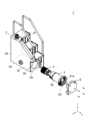
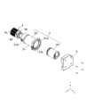
図1は、本発明の実施形態であるタンク装置1の概略を示す分解斜視図である。図2は、タンク装置1の一部であるリターンフィルタ3、ストレーナ4及び蓋体5の概略を示す分解斜視図である。 FIG. 1 is an exploded perspective view showing an outline of a
タンク装置1は、主として、タンク2と、リターンフィルタ3と、ストレーナ4と、蓋体5と、を有する。 The
タンク2は、内部が空洞であり、作動油が貯留される。タンク2は、主として、側面2a、2c、2dと、底面2eと、階段状に形成された上面2fと、を有する。ただし、タンク2の形状はこれに限られない。 The
側面2aには、挿入孔2bが設けられる。挿入孔2bは、底面2e近傍に形成されている。 An
タンク2の内部には、リターンフィルタ3及びストレーナ4が設けられている。リターンフィルタ3及びストレーナ4は、一体化されており、タンク2の側面2aに形成された挿入孔2bを介してタンク2の内部に設けられる。 A
挿入孔2bが底面2e近傍に形成されているため、リターンフィルタ3及びストレーナ4は、底面2e近傍に横向きに設けられる。なお、本発明において、横向きとは、中心軸が水平方向に沿った状態や、中心軸が水平方向に対して少し(例えば、10度前後)傾いた状態を含むものとする。 Since the
ストレーナ4及び筐体30が挿入孔2bからタンク2の内部に挿入され、フランジ部31a(後に詳述)が側面2aに当接して固定されることでリターンフィルタ3及びストレーナ4がタンク2の内部に設けられる。 The
リターンフィルタ3は、主として、フィルタエレメント20と、筐体30と、を有する。筐体30は、一方の端面が開口しており、この開口が開口部31bである。所定期間使用後、使用済みのフィルタエレメント20を開口部31bを介して筐体30から取り出す。また、新しいフィルタエレメント20は、開口部31bを介して筐体30の内部に設けられる。開口部31bの周囲には、筐体30を側面2aに取り付けるためのフランジ部31aが設けられている。リターンフィルタ3については後に詳述する。 The
ストレーナ4は、油圧ポンプへの異物の進入を防止するため、タンク2の内部に設けられる。タンク2内に貯留された作動油は、ストレーナ4を介して油圧ポンプ(図示せず)に吸引されて、再度油圧装置へ供給される。ストレーナ4は、主として、濾材4aと、上端支持部材4bと、下端支持部材4cと、を有する。濾材4aは、例えば多数の孔が形成された金属製の板状部材であり、両端を連結して円筒状に丸めることによって略円筒形状に形成される。なお、濾材4aの形態はこれに限られない。上端支持部材4bは、濾材4aの上端を覆う板状部材であり、下端支持部材4cは、濾材4aの下端を覆う板状部材である。 A
蓋体5は、開口部31bを覆うように、リターンフィルタ3及びタンク2に設けられる。なお、蓋体5は、リターンフィルタ3のみに設けられてもよい。 The
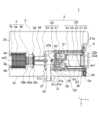
図3は、タンク装置1の概略を示す断面図である。図3では、リターンフィルタ3及びストレーナ4の中心軸ax1、ax2を通り、xy平面に沿った面でタンク装置1を切断した図である。図3においては、断面を示すハッチングを省略している。 FIG. 3 is a cross-sectional view showing an outline of the
リターンフィルタ3は、フランジ部31aが側面2aに固定されることで、タンク2の内部に設けられる。ストレーナ4は、下端支持部材4cの略中央部分に形成された貫通孔4dに、側面2dに形成された流出口2gが挿入されることで、タンク2に位置決めされて固定される。貫通孔4dと流出口2gとの間には、作動油が漏れないようにシールするシール部材(例えば、Oリング)58が設けられている。 The
本発明の形態では、リターンフィルタ3の中心軸ax1と、ストレーナ4の中心軸ax2とが略一致しているが、中心軸ax1、ax2に沿って見たときにリターンフィルタ3とストレーナ4とが重なっていればよい。これにより、リターンフィルタ3及びストレーナ4を狭いスペースに設けることができ、タンク2の大きさを小さくすることができる。 In the embodiment of the present invention, the central axis ax1 of the
フィルタエレメント20は、主として、濾材21と、持ち手部22と、外筒23と、バルブ受け部材24と、内筒25と、を有する。 The
濾材21は、径方向に厚みを有する略中空円筒形状である。濾材21は、合成樹脂や紙等を用いたシート状の濾紙をひだ折りにし、ひだ折りにした濾紙の両端を連結して円筒状に丸めることによって形成される。 The
外筒23及び内筒25は、耐腐食性の高い材料(樹脂又は金属)を用いて形成された略中空円筒形状の部材である。内筒25には、作動油が通過する孔が全面に形成されている。外筒23は濾材21の外側に設けられ、内筒25は濾材21の内側に設けられる。なお、内筒25は必須ではない。 The
濾材21、外筒23及び内筒25の一方の端(図3における右端、+y側の端)には、持ち手部22が設けられる。持ち手部22は、濾材21、外筒23及び内筒25の上端を覆うように、濾材21、外筒23及び内筒25に固定される。持ち手部22には、作業者がフィルタエレメント20を把持するための部材である把持部22aが設けられている。また、持ち手部22は、内筒25の内周面に嵌合する筒状部22bを有し、フィルタエレメント20の蓋として役割を有する。 A
また、持ち手部22には、差圧センサ、温度計等の測定部26が設けられている。差圧センサは、流入空間S3と流出空間S4との圧力差(差圧)を検出する。 Further, the
濾材21、外筒23及び内筒25の他方の端(図3における左端、-y側の端)には、バルブ受け部材24が設けられる。バルブ受け部材24は、耐腐食性の高い材料(樹脂又は金属)を用いて形成される。バルブ受け部材24については後に詳述する。 A
筐体30は、主として、フィルタエレメント20が内部に設けられるフィルタケース31と、フィルタケース31の内部に設けられたヘッド32と、フィルタケース31に設けられた流出管34と、背圧バルブ38と、を有する。 The
フィルタケース31は、略有底筒形状の部材であり、金属又は樹脂により形成される。フィルタケース31の+y側の端には、フランジ部31a及び開口部31b(図3では図示省略)が設けられている。開口部31bからフィルタケース31内部にフィルタエレメント20が挿入された後で、開口部31bは蓋体5により覆われる。 The
フィルタケース31の開口部33bと反対側(-y側)の端には、底面31cが設けられている。また、フィルタケース31の側面には、孔31dが形成されている。 A
なお、本実施の形態では、フィルタケース31は、略筒状の部材と、有底略筒形状の部材とを組み合わせて形成されているが、フィルタケース31の構成はこれに限られない。 In this embodiment, the
フィルタケース31の内部には、フィルタエレメント20のバルブ受け部材24が装着されるヘッド32が設けられている。 A
ヘッド32は、主として、プレート35と、圧縮ばね36と、本体部37と、を有する。プレート35は、圧縮ばね36を介して本体部37に設けられる。 The
フィルタケース31と本体部37との間には、シール部材50(例えば、Oリング)が設けられる。シール部材50により、フィルタケース31と本体部37との間から液体が外部に漏れないようにシールされる。ヘッド32については後に詳述する。 A seal member 50 (for example, an O-ring) is provided between the
管状部材33は、タンク2の外部とフィルタケース31の内部とを連通する略筒状の部材である。本体部37の側面には、濾過前の油を流入空間S1に導く流入口37aが設けられている。流入口37aは、本体部37に設けられた孔37bの一方の端の開口部である。孔31d及び流入口37aには、管状部材33が挿入される。また、タンク2の側面2a及び側面2dに隣接する側面2cには、孔2hが設けられており、孔2hには管状部材33が挿入されている。この結果、管状部材33を介して、濾過前の作動油が流入空間S1に導かれる。 The
流出管34は、略筒形状(ここでは、略円筒形状)であり、底面31cに設けられている。流出管34は、ヘッド32を介して流出空間S2と連通している。 The
流出管34の先端(-y側、底面31c側と逆側)には、背圧バルブ38が設けられている。流出管34及び背圧バルブ38は、濾材21を通過した濾過後の作動油をタンク2に流出させる流出部を構成する。背圧バルブ38は、主として、弾性部材38aと、弾性部材38aの一端が設けられる固定部38bと、弾性部材38aの他端が設けられる移動部材38cと、を有する。固定部38bは、ストレーナ4と当接している。 A
フィルタケース31の内部の圧力が上昇するのに伴って、移動部材38cが流出管34に当接する閉状態(図3に示す状態)から、移動部材38cが流出管34に当接しない開状態へと、移動部材38cが弾性部材38aの付勢力に抗して移動する。 As the pressure inside the
作業機械等のエンジンの動作が停止している場合には、フィルタケース31内に作動油が含まれていない。したがって、背圧バルブ38は閉状態にある。作業機械のエンジンが稼動し、作動油の流量が増加すると、フィルタケース31の内部が作動油で満たされ、フィルタケース31の内部の圧力が十分に高くなる。したがって、作動油が、弾性部材38aの付勢力に抗して移動部材38cを押し下げ、背圧バルブ38が開状態となる。その結果、濾過後の作動油が流出管34から流出する。 When the operation of the engine of the work machine or the like is stopped, the
また、本体部37には、バルブ48が設けられている。流出管34は、バルブ48を覆うように設けられる。バルブ48は、流入空間S1の圧力と筐体30の外部空間の圧力との差に応じて開閉する。バルブ48は公知であるため詳細な説明を省略する。 A
また、本体部37に図示しない空気抜き弁を設けてもよい。空気抜き弁は、本体部37の内部に空気が溜まった時に開いて空気をタンク2内部に排出する。本実施の形態では、リターンフィルタ3が横向きに設けられているため、本体部37の側面の上側(+z側)に空気抜き弁を設ける。 Also, an air vent valve (not shown) may be provided in the
次に、バルブ受け部材24及びヘッド32について説明する。図4は、フィルタエレメント20がヘッド32に装着される前の状態のリターンフィルタ3を部分的に拡大した断面図である。図4においては、断面を示すハッチングを一部省略している。 Next, the
バルブ受け部材24は、主として、内筒部24aと、板状部24bと、外筒部24cと、を有する。内筒部24aの先端が濾材21の端部に設けられたプレート21aの内周面と嵌合し、外筒23が外筒部24cの先端に形成された溝24dに嵌合されることで、濾材21、外筒23及びバルブ受け部材24が一体化される。 The
板状部24bは、略円板形状であり、略筒状の孔24e、24fが形成されている。孔24eは、濾材21へ濾過されていない汚れた油(濾過前の油)を流入させる油導入口であり、孔24fは、濾材21で濾過された油(濾過後の油)を流出させる油導出口である。孔24eは流入空間S3と繋がっており、孔24fは流出空間S4と繋がっている。 The plate-
また、バルブ受け部材24には、弁40が設けられている。弁40は、孔24eや孔24fの内部に挿入されることで孔24eや孔24fを塞ぐカバー部材41と、カバー部材41に力を付勢する圧縮ばね42と、を有する。 A
カバー部材41は、孔24e、24fの内部に挿入される略円板形状の挿入部41aと、挿入部41aの表面(+z側の面)に設けられたフランジ部41bと、を有する。フランジ部41bは、板状であり、外径が孔24e、24fの内径より大きい。 The
挿入部41aは、略円筒形状であり、外径が孔24e、24fの内径と略同一である。挿入部41aの外周には溝41cが形成され、溝41cにはシール部材(例えば、Oリング)55が設けられる。挿入部41aの裏面(-z側の面)41dは、全体が略円錐台の凹形状である。 The insertion portion 41a has a substantially cylindrical shape and an outer diameter that is substantially the same as the inner diameters of the
圧縮ばね42は、例えばコイルばねであり、一端が内筒部24aの底面裏側(突起部24g)に設けられ、他端がカバー部材41(フランジ部41bの表面に形成された突起部41e)に設けられる。したがって、圧縮ばね42は、カバー部材41に-y方向の力を付勢する。 The
圧縮ばね42により-y方向の力が付勢されると、挿入部41aが孔24e又は孔24fに挿入されて、フランジ部41bが板状部24bに当接する位置にカバー部材41が配置されて、カバー部材41が孔24e又は孔24fを塞ぐ。この状態は、弁40が閉じた状態である。 When the
本体部37は、フィルタケース31の内側を、フィルタエレメント20へ濾過前の油を流入させる流入空間S1と、フィルタエレメント20から流出された濾過後の油をタンク装置1の外部へ流出させる流出空間S2と、に分割する。 The
圧縮ばね36は、一端がプレート35の裏面、他端が本体部37の表面に設けられ、プレート35に上向き(+y向き)の力を付勢する。したがって、プレート35は、圧縮ばね36の自然長だけ本体部37から離れた位置に配置される。 The
プレート35は、全体として略円板形状であり、略板状の本体部35aと、本体部35aから上方に突出して形成された円筒部35bと、を有する。本体部35aの外周面には溝35cが形成され、溝35cにはシール部材51(例えば、Oリング)が設けられる。シール部材51により、フィルタケース31と本体部35aとの間から液体が漏れないようにシールされる。 The
プレート35には、本体部35aを板圧方向に貫通する孔35d、35eが形成される。孔35dは、濾過前の油が通過する油導入口であり、孔35eは、濾過後の油が通過する油導出口である。孔35dの直径は、孔24eの直径と略同一であり、孔35eの直径は、孔24fの直径と略同一である。
本体部35aには、-y方向に突出する円筒部35fが形成される。円筒部35fの中空部は、孔35dと連通する。円筒部35fの先端は、本体部37の上面に形成される円筒部37fの内部に摺動可能に設けられる。円筒部37f及び円筒部35fの内部空間は流入空間S1であり、円筒部37f及び円筒部35fの外部空間は流出空間S2である。円筒部35fは、孔35dよりも細い。 A cylindrical portion 35f protruding in the -y direction is formed in the
円筒部35fの外周にはシール部材57が設けられ、円筒部37fと円筒部35fの間から液体が漏れないようにシールされる。 A sealing
また、本体部35aには、孔35eの下孔として、孔35eより細い孔35gが形成される。孔35gの直径は、円筒部35fの直径より細い。 A
孔35d、35eには、それぞれカバー部材45が設けられる。カバー部材45は、本体部37に設けられたシャフト37eの先端に固定される。 A
カバー部材45は、孔35d、35eの内部に挿入される厚板状の挿入部45aを有する。挿入部45aは、略円筒形状であり、外径が孔35d、35eの内径と略同一である。挿入部45aの外周には溝45cが形成され、溝45cにはシール部材(例えば、Oリング)56が設けられる。 The
挿入部45aの裏面には、挿入部45aより細い突出部45dが形成される。シャフト37eは、突出部45dに設けられる。突出部45dは円筒部35f、孔35gより細く、挿入部45aは円筒部35f、孔35gより太い。 A protruding
カバー部材45と圧縮ばね36は、弁46を構成する。圧縮ばね36がプレート35を押し上げることで、挿入部45aがそれぞれ孔35d、35eを塞ぐ位置(突出部45dが円筒部35f又は孔35gに挿入される位置)にプレート35が配置される。この状態は、弁46が閉じた状態である。弁46が閉じた状態では、シール部材56により挿入部45aと孔35d、35eとの間から液体が漏れないようにシールされる。 The
挿入部45aの表面45bは、全体が略円錐台の凸形状である。この表面45bと裏面41dとは、相補的な形状である。 The
次に、このように形成されたタンク装置1の組み立て、部品交換及び作用について説明する。 Next, assembly, part replacement and operation of the
タンク装置1を使用する前に、筐体30にフィルタエレメント20をセットする。具体的には、まず、図1、2に示すように、作業者は、フィルタエレメント20を開口部31bから挿入する。そのままフィルタエレメント20がフィルタケース31の奥まで挿入されると、図5に示すように、カバー部材41の裏面41dと、カバー部材45の表面45bとが当接し、板状部24bの外周(シール部材52)と円筒部35bとが嵌合する。 The
図5は、フィルタエレメント20がヘッド32に装着された状態のリターンフィルタ3を部分的に拡大した断面図である。図5においては、断面を示すハッチングを一部省略している。 FIG. 5 is a partially enlarged sectional view of the
作業者がフィルタエレメント20を押し込むことにより、カバー部材41の裏面41dと、カバー部材45の表面45bとが当接したまま、圧縮ばね36の付勢力に抗してバルブ受け部材24がプレート35を押圧する。その結果、圧縮ばね36が圧縮され、バルブ受け部材24及びプレート35が押し下げられる(-y方向に移動する、図5太矢印参照)。 When the operator pushes in the
その結果、圧縮ばね42の付勢力に抗して、カバー部材41は、カバー部材45により押圧されて押し上げられる(+y方向に移動する、図5太矢印参照)。 As a result, the
カバー部材41の裏面41dと、カバー部材45の表面45bとは相補的な形状であるため、裏面41d全体が表面45b全体と当接している。したがって、圧縮ばね42の付勢力に抗してカバー部材41が確実に押し上げられる。 Since the rear surface 41d of the
フィルタエレメント20がヘッド32に装着されたときは、バルブ受け部材24の板状部24bがプレート35の円筒部35bに嵌合するため、孔35dと孔24eとが連通し、孔24fと孔35eとが連通する。そして、カバー部材41が押し上げられることで、孔24e及び孔35dが開かれ、流入空間S1と流入空間S3とが連通する。また、孔24f及び孔35eが開かれ、流出空間S2と流出空間S4とが連通する。 When the
フィルタエレメント20を筐体30にセットし、開口部31bを蓋体5で覆うことで、タンク装置1が使用可能となる(図3参照)。 By setting the
図5に示すように、流入口37aから流入した濾過前の油は、流入空間S1を通過してフィルタエレメント20の流入空間S3へ流入する。流入空間S3へ導かれた濾過前の油は、濾材21を外側から内側へ通過することにより濾過されて、流出空間S4へ導かれる。 As shown in FIG. 5 , the unfiltered oil that has flowed in from the
濾過後の油は、フィルタエレメント20から排出されて流出空間S2へ導かれる。流出空間S2へ導かれた濾過後の油は、流出管34を通過してタンク装置1の外部へと排出される。 The filtered oil is discharged from the
カバー部材41の裏面41dと、カバー部材45の表面45bとは相補的な形状であるため、裏面41d全体が表面45b全体と当接している。したがって、タンク装置1を使用しても、裏面41dには濾過前の油及び濾過後の油(以下、作動油という)が付着しない。 Since the rear surface 41d of the
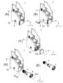
所定期間使用後、使用済みのフィルタエレメント20を筐体30から取り出し、新しいフィルタエレメント20と交換する。図6は、フィルタエレメント20の交換の様子を模式的に示す図である。 After being used for a predetermined period, the used
図6(A)に示す交換作業前のタンク装置1に対して、作業者は、図6(B)に示すように蓋体5を外し、把持部22aを把持して、図6(C)に示すようにフィルタエレメント20を+y方向に引き出す。その結果、図4に示すように、圧縮ばね36が元の長さに戻り、プレート35及びバルブ受け部材24が押し上げられ、カバー部材41の裏面41dと、カバー部材45の表面45bとの当接が外れ、板状部24bと円筒部35bとの嵌合が外れ、フィルタエレメント20と筐体30とが分離される。 As shown in FIG. 6(A), the operator removes the
プレート35が押し上げられると、図4に示すように、カバー部材45が孔35d、35eを塞ぐ(弁46が閉じる)。弁46が閉じているため、ヘッド32の内部に残っている作動油は、ヘッド32の内部に閉じ込められる。本実施の形態では、リターンフィルタ3を横向きに設置しているが、フィルタエレメント20の交換時に弁46を閉じることで、作動油がタンク2から漏れないようにする。 When the
それと同時に、カバー部材41が、圧縮ばね42により押し下げられる。その結果、図4に示すように、カバー部材41が孔24e、孔24fを塞ぐ(弁40が閉じる)。弁40が閉じているため、フィルタエレメント20の内部に残っている作動油は、フィルタエレメント20の内部に閉じ込められ、フィルタエレメント20の外に流出しない。 At the same time, the
このようにしてフィルタエレメント20を筐体30の外側に取り出したら、すでに説明した手順で新たなフィルタエレメント20を筐体30にセットする。 After removing the
また、本実施の形態のタンク装置1は、ストレーナ4の交換も可能である。図7は、ストレーナ4の交換の様子を模式的に示す図である。 Further, in the
図7(A)に示す交換作業前のタンク装置1に対して、作業者は、図7(B)に示すように、側面2cからフランジ2iを外し、孔2hから管状部材33を引き抜く。その後、作業者は、図7(C)に示すように蓋体5を外し、図7(D)に示すようにリターンフィルタ3及びストレーナ4を+y方向に引き出す。リターンフィルタ3及びストレーナ4は一体化されているため、フランジ部31aをタンク2から取り外すことで、リターンフィルタ3及びストレーナ4をタンク2から引き出すことができる。 As shown in FIG. 7(B), the operator removes the
作業者は、図7(E)に示すように、リターンフィルタ3とストレーナ4とを分解する。これにより、使用後のストレーナ4がリターンフィルタ3から取り外される。 The operator disassembles the
その後、作業者は、新たなストレーナ4をリターンフィルタ3に設け、リターンフィルタ3及びストレーナ4を挿入孔2bからタンク2内部に挿入し、フランジ部31aを側面2aに固定し、側面2aに蓋体5を取り付ける。また、作業者は、孔2hから管状部材33を挿入し、フランジ2iを側面2cに取り付ける。これにより、新たなストレーナ4がタンク2にセットされる。 After that, the operator installs a
本実施の形態によれば、弁40、46を設けて、フィルタエレメント20の交換時にタンク2内部の作動油やフィルタエレメント20内部の作動油が漏れないようにしたため、タンク2の内部にリターンフィルタ3を横向きに設置することができる。したがって、フィルタエレメント20を交換するときに、タンク2の上からフィルタエレメント20を引き抜く必要がない。すなわち、作業者が高所で作業を行う必要がなく、交換作業の安全性を高めることができる。 According to the present embodiment, the
また、本実施の形態によれば、リターンフィルタ3及びストレーナ4を一体化してタンク2の内部に設けたため、タンク2を小型化することができる。また、ストレーナ4を流出口2gを介して側面2dに設け、リターンフィルタ3を側面2aに設け、平行な2つの側面2a、2dでリターンフィルタ3及びストレーナ4を挟むようにしたため、リターンフィルタ3及びストレーナ4が横向きであっても、リターンフィルタ3及びストレーナ4をタンク2の内部にしっかり固定することができる。 Further, according to the present embodiment, the
建設機械は凹凸のある路面を走行することが多いため、建設機械と同様に、タンク装置1も上下に大きく振動する。例えば、リターンフィルタ3の先端にストレーナ4が設けられておらず、リターンフィルタ3が側面2aのみに取り付けられている(いわゆる片持ち)構造だと、タンク装置1の振動に合わせてリターンフィルタ3の先端が上下方向に移動してしまい、タンク装置1の強度が低下するおそれがある。それに対し、本実施の形態のように、リターンフィルタ3の先端にストレーナ4を設け、タンク2の対向する2つの側面2a、2dでリターンフィルタ3及びストレーナ4を挟む(いわゆる両持ち)構造とすることで、タンク装置1の強度を高めることができる。 Since the construction machine often travels on uneven road surfaces, the
さらに、リターンフィルタ3の側面を管状部材33を介して側面2cに取り付けることで、タンク装置1の振動に合わせてリターンフィルタ3及びストレーナ4が上下方向に振動することを防ぎ、タンク装置1の強度をさらに高めることができる。 Furthermore, by attaching the side surface of the
なお、本実施の形態では、リターンフィルタ3及びストレーナ4を底面2eの近傍に設けたが、リターンフィルタ3及びストレーナ4は底面2eから離れた位置に設けられていてもよい。ただし、交換作業の安全性を考慮すると、リターンフィルタ3及びストレーナ4が底面2eの近傍に設けられていることが望ましい。 Although the
また、本実施の形態では、リターンフィルタ3及びストレーナ4を一体化してタンク2内部に設けたが、リターンフィルタ3及びストレーナ4を一体化することは必須ではない例えば、リターンフィルタ3のみを横向きにしてタンク2内に設けてもよい。 In addition, in the present embodiment, the
ただし、リターンフィルタ3の先端にストレーナ4が設けられていない場合には、タンク装置1の振動に合わせてリターンフィルタ3の先端が上下方向に移動することを防ぐため、本実施の形態のように、リターンフィルタ3の側面を管状部材33を介して側面2cに取り付けることが望ましい。しかしながら、強度の面からは、リターンフィルタ3の先端にストレーナ4を設け、タンク2の対向する2つの側面2a、2dでリターンフィルタ3及びストレーナ4を挟む構造とすることがさらに望ましい。 However, when the
また、本実施の形態では、流出管34とストレーナ4との間に背圧バルブ38が設けられていたが、背圧バルブ38は必須ではない。背圧バルブ38を有しない場合には、流出管34の側面に孔を設け、流出管34の先端をストレーナ4に設ければよい。 Also, in the present embodiment, the
また、本実施の形態では、挿入部41aの裏面41dが略円錐台の凹形状であり、挿入部45aの表面45bが略円錐台の凸形状であるが、裏面41dが略円錐台の凸形状であり、表面45bが略円錐台の凹形状であってもよい。また、裏面41dと表面45bとは相補的な形状である必要があるが、これらの形状は略円錐台の凸形状及び凹形状に限られない。 In the present embodiment, the rear surface 41d of the insertion portion 41a has a substantially truncated cone concave shape, and the insertion portion 45a has a substantially truncated cone convex shape on the front surface 45b. , and the
また、本実施の形態では、挿入部41a及び孔24e、24fの直径と、挿入部45a及び孔35d、35eの直径とが略同一であるが、これらの直径は略同一なくてもよく、挿入部45a及び孔35d、35eの直径が、挿入部41a及び孔24e、24fの直径以上であればよい。 In the present embodiment, the insertion portion 41a and the
以上、この発明の実施形態を、図面を参照して詳述してきたが、具体的な構成はこの実施形態に限られるものではなく、この発明の要旨を逸脱しない範囲の設計変更等も含まれる。例えば、上記の実施例は本発明を分かりやすく説明するために詳細に説明したものであり、必ずしも説明した全ての構成を備えるものに限定されるものではない。また、実施形態の構成の一部を他の実施形態の構成に置き換えることが可能であり、また、実施形態の構成に他の構成の追加、削除、置換等をすることが可能である。 Although the embodiments of the present invention have been described in detail with reference to the drawings, the specific configuration is not limited to these embodiments, and design changes and the like are also included within the scope of the gist of the present invention. . For example, the above embodiments have been described in detail for easy understanding of the present invention, and are not necessarily limited to those having all the described configurations. Also, part of the configuration of the embodiment can be replaced with the configuration of another embodiment, and it is possible to add, delete, or replace the configuration of the embodiment with another configuration.
また、本発明において、「略」とは、厳密に同一である場合のみでなく、同一性を失わない程度の誤差や変形を含む概念である。例えば、「略円筒形状」とは、厳密に円筒形状の場合には限られない。また、例えば、単に略中央等と表現する場合において、厳密に中央等の場合のみでなく、略中央等の場合を含むものとする。 In addition, in the present invention, the term "substantially" is not limited to the case of being exactly the same, but is a concept that includes errors and deformations to the extent that the identity is not lost. For example, "substantially cylindrical" is not strictly limited to a cylindrical shape. Further, for example, the expression "approximately at the center" includes not only the exact center, but also the approximate center.
1 :タンク装置
2 :タンク
2a、2c、2d:側面
2b :挿入孔
2e :底面
2f :上面
2g :流出口
2h :孔
2i :フランジ
3 :リターンフィルタ
4 :ストレーナ
4a :濾材
4b :上端支持部材
4c :下端支持部材
4d :貫通孔
5 :蓋体
20 :フィルタエレメント
21 :濾材
21a :プレート
22 :持ち手部
22a :把持部
22b :筒状部
23 :外筒
24 :バルブ受け部材
24a :内筒部
24b :板状部
24c :外筒部
24d :溝
24e、24f:孔
24g :突起部
25 :内筒
26 :測定部
30 :筐体
31 :フィルタケース
31a :フランジ部
31b :開口部
31c :底面
31d :孔
32 :ヘッド
33 :管状部材
33b :開口部
34 :流出管
35 :プレート
35a :本体部
35b :円筒部
35c :溝
35d、35e、35g:孔
35f :円筒部
36 :圧縮ばね
37 :本体部
37a :流入口
37b :孔
37e :シャフト
37f :円筒部
38 :背圧バルブ
38a :弾性部材
38b :固定部
38c :移動部材
40 :弁
41 :カバー部材
41a :挿入部
41b :フランジ部
41c :溝
41d :裏面
41e :突起部
42 :圧縮ばね
45 :カバー部材
45a :挿入部
45b :表面
45c :溝
45d :突出部
46 :弁
48 :バルブ
50、51、52、55、56、57、58:シール部材Reference Signs List 1: Tank device 2: Tanks 2a, 2c, 2d: Side surface 2b: Insertion hole 2e: Bottom surface 2f: Top surface 2g: Outflow port 2h: Hole 2i: Flange 3: Return filter 4: Strainer 4a: Filter medium 4b: Upper end support member 4c : Lower end support member 4d : Through hole 5 : Lid 20 : Filter element 21 : Filter medium 21a : Plate 22 : Handle portion 22a : Grip portion 22b : Cylindrical portion 23 : Outer cylinder 24 : Valve receiving member 24a : Inner cylinder 24b: Plate-like portion 24c: Outer cylinder portion 24d: Grooves 24e, 24f: Hole 24g: Projection portion 25: Inner cylinder 26: Measuring portion 30: Housing 31: Filter case 31a: Flange portion 31b: Opening portion 31c: Bottom surface 31d : Hole 32 : Head 33 : Tubular member 33b : Opening 34 : Outflow tube 35 : Plate 35a : Body portion 35b : Cylindrical portion 35c : Grooves 35d, 35e, 35g : Hole 35f : Cylindrical portion 36 : Compression spring 37 : Body portion 37a: Inflow port 37b: Hole 37e: Shaft 37f: Cylindrical portion 38: Back pressure valve 38a: Elastic member 38b: Fixed portion 38c: Moving member 40: Valve 41: Cover member 41a: Insertion portion 41b: Flange portion 41c: Groove 41d : Back surface 41e : Projection 42 : Compression spring 45 : Cover member 45a : Insertion portion 45b : Surface 45c : Groove 45d : Projection 46 : Valve 48 : Valves 50, 51, 52, 55, 56, 57, 58: Seal member
Claims (3)
Translated fromJapanese前記タンクの内部に横向きに設けられたリターンフィルタであって、一端が開口部である略有底筒形状のフィルタケースと、前記フィルタケースの内部に設けられたヘッドと、略筒形状の濾材、前記濾材の端面に設けられたバルブ受け部材、及び前記バルブ受け部材に設けられた弁を有するフィルタエレメントと、を備えたリターンフィルタと、
前記開口部を覆うように前記リターンフィルタに設けられた蓋体と、
前記タンクの内部に横向きに設けられたストレーナであって、前記リターンフィルタに設けられたストレーナと、
を備えたタンク装置であって、
前記タンクは、略平行な2つの側面であるタンク第1側面及びタンク第2側面を有し、
前記タンク第1側面には、挿入孔が形成され、
前記フィルタケースは、前記タンク第1側面に設けられ、かつ、前記挿入孔から前記タンクの内部に挿入され、
前記フィルタケースの底面には、前記濾材を通過した液体を前記タンクに流出させる流出部が設けられており、
前記ストレーナは、一端が前記流出部に設けられ、他端が前記タンク第2側面に設けられており、
前記バルブ受け部材は、前記濾材へ油を流入させる略筒状の第1孔及び前記濾材で濾過された油である濾過後の油を流出させる第2孔が設けられた略板状の板状部を有し、
前記弁は、前記第1孔の内部に挿入されて前記第1孔を塞ぐ第1挿入部を有する第1カバー部材、及び、前記第1挿入部が前記第1孔を塞ぐ位置に前記第1カバー部材を配置する第1圧縮ばねを有する第1弁と、及び前記第2孔の内部に挿入されて前記第2孔を塞ぐ第2挿入部を有する第2カバー部材、及び、前記第2挿入部が前記第2孔を塞ぐ位置に前記第2カバー部材を配置する第2圧縮ばねを有する第2弁と、を有し、
前記ヘッドには、第3孔及び第4孔が形成されたプレートと、前記第3孔の内部に挿入可能な第3挿入部を有する第3カバー部材と、前記第4孔の内部に挿入可能な第4挿入部を有する第4カバー部材と、前記第3カバー部材が前記第3孔を塞ぎ、前記第4カバー部材が前記第4孔を塞ぐ位置に前記プレートを配置するように前記プレートに前記開口部に向かう方向の力を付勢する第3圧縮ばねと、が設けられ、
前記フィルタエレメントが前記開口部から前記フィルタケースの内部に挿入されると、前記第1カバー部材の第1面と前記第3カバー部材の第3面とが当接し、前記第2カバー部材の第2面と前記第4カバー部材の第4面とが当接し、前記プレートと前記バルブ受け部材とが当接し、
前記フィルタエレメントが前記フィルタケースの内部に押し込まれると、前記第3圧縮ばねの付勢力に抗して前記バルブ受け部材が前記プレートを押圧し、前記第1圧縮ばねの付勢力に抗して前記第3カバー部材が前記第1カバー部材を押圧し、かつ前記第2圧縮ばねの付勢力に抗して前記第4カバー部材が前記第2カバー部材を押圧し、
前記フィルタエレメントが前記フィルタケースの奥まで挿入されると、前記第1孔と前記第3孔とが連通し、前記第2孔と前記第4孔とが連通して、前記フィルタエレメントの内部空間と前記ヘッドの内部空間とが連通する
ことを特徴とするタンク装置。a tank with a hollow interior;
A return filter provided horizontally inside the tank, the filter case having a substantially bottomed cylindrical shape having an opening at one end, a head provided inside the filter case, and a substantially cylindrical filter material, a return filter comprising: a valve receiving member provided on an end face of the filter medium; and a filter element having a valve provided on the valve receiving member;
a cover provided on the return filter so as to cover the opening;
a strainer provided laterally inside the tank, the strainer provided on the return filter;
A tank device comprising
The tank has two substantially parallel sides, a tank first side and a tank second side,
An insertion hole is formed in the first side surface of the tank,
The filter case is provided on the first side surface of the tank and is inserted into the tank through the insertion hole,
The bottom surface of the filter case is provided with an outflow portion for causing the liquid that has passed through the filter medium to flow out to the tank,
The strainer has one end provided at the outflow portion and the other end provided at the second side surface of the tank,
The valve receiving member has a substantially plate-like shape provided with a substantially cylindrical first hole for allowing oil to flow into the filter medium and a second hole for discharging oil filtered by the filter medium after filtering. has a part
The valve includes: a first cover member having a first insertion portion inserted into the first hole to close the first hole; a first valve having a first compression spring for disposing a cover member; a second cover member having a second insertion portion inserted into the second hole to block the second hole; and the second insertion a second valve having a second compression spring that positions the second cover member at a position where the portion closes the second hole;
The head includes a plate formed with a third hole and a fourth hole, a third cover member having a third insertion portion that can be inserted into the third hole, and a cover member that can be inserted into the fourth hole. a fourth cover member having a fourth insertion portion; and the third cover member closes the third hole, and the fourth cover member closes the fourth hole. a third compression spring that biases a force in a direction toward the opening,
When the filter element is inserted into the inside of the filter case through the opening, the first surface of the first cover member and the third surface of the third cover member abut against each other, and the third surface of the second cover member two surfaces and the fourth surface of the fourth cover member are in contact, the plate and the valve receiving member are in contact,
When the filter element is pushed into the filter case, the valve receiving member presses the plate against the biasing force of the third compression spring, and the valve receiving member presses the plate against the biasing force of the first compression spring. the third cover member presses the first cover member, and the fourth cover member presses the second cover member against the biasing force of the second compression spring;
When the filter element is inserted all the way into the filter case, the first hole and the third hole communicate, the second hole and the fourth hole communicate, and the internal space of the filter element and the internal space of the head communicate with each other.
前記タンクは、前記タンク第1側面及び前記タンク第2側面に隣接する側面であるタンク第3側面を有し、
前記タンク第3側面及び前記フィルタケースには、それぞれ前記管状部材が挿入される孔が設けられている
ことを特徴とする請求項1に記載のタンク装置。The return filter has a tubular member communicating between the outside of the tank and the inside of the filter case,
the tank has a tank third side adjacent to the tank first side and the tank second side;
The tank device according to claim 1, wherein the third side surface of the tank and the filter case are provided with holes into which the tubular members are inserted.
ことを特徴とする請求項1又は2に記載のタンク装置。The tank device according to claim 1 or 2, wherein the return filter and the strainer are provided near the bottom surface of the tank.
Priority Applications (6)
| Application Number | Priority Date | Filing Date | Title |
|---|---|---|---|
| JP2019124744AJP7262325B2 (en) | 2019-07-03 | 2019-07-03 | tank equipment |
| EP20835664.2AEP3995197B8 (en) | 2019-07-03 | 2020-06-26 | Tank device |
| PCT/JP2020/025235WO2021002291A1 (en) | 2019-07-03 | 2020-06-26 | Tank device |
| CN202010634597.0ACN112169427B (en) | 2019-07-03 | 2020-07-02 | Box device |
| CN202021289663.7UCN212396091U (en) | 2019-07-03 | 2020-07-02 | Box device |
| US17/551,258US12025085B2 (en) | 2019-07-03 | 2021-12-15 | Tank device |
Applications Claiming Priority (1)
| Application Number | Priority Date | Filing Date | Title |
|---|---|---|---|
| JP2019124744AJP7262325B2 (en) | 2019-07-03 | 2019-07-03 | tank equipment |
Publications (2)
| Publication Number | Publication Date |
|---|---|
| JP2021010854A JP2021010854A (en) | 2021-02-04 |
| JP7262325B2true JP7262325B2 (en) | 2023-04-21 |
Family
ID=73919035
Family Applications (1)
| Application Number | Title | Priority Date | Filing Date |
|---|---|---|---|
| JP2019124744AActiveJP7262325B2 (en) | 2019-07-03 | 2019-07-03 | tank equipment |
Country Status (5)
| Country | Link |
|---|---|
| US (1) | US12025085B2 (en) |
| EP (1) | EP3995197B8 (en) |
| JP (1) | JP7262325B2 (en) |
| CN (2) | CN212396091U (en) |
| WO (1) | WO2021002291A1 (en) |
Families Citing this family (4)
| Publication number | Priority date | Publication date | Assignee | Title |
|---|---|---|---|---|
| USD977610S1 (en)* | 2019-03-19 | 2023-02-07 | Soclean Inc. | Filter cartridge |
| JP7262325B2 (en)* | 2019-07-03 | 2023-04-21 | ヤマシンフィルタ株式会社 | tank equipment |
| EP4467220A4 (en)* | 2022-01-20 | 2025-04-02 | Yamashin-Filter Corp. | SUCTION STRAINER |
| JP2023150437A (en)* | 2022-03-31 | 2023-10-16 | ヤマシンフィルタ株式会社 | suction strainer |
Citations (3)
| Publication number | Priority date | Publication date | Assignee | Title |
|---|---|---|---|---|
| JP2000117015A (en) | 1998-10-19 | 2000-04-25 | Nippon Walbro:Kk | Fuel tank filter device |
| EP1449572A2 (en) | 2003-02-21 | 2004-08-25 | Deere & Company | Filter assembly, gearbox casing and vehicle |
| JP2017196552A (en) | 2016-04-26 | 2017-11-02 | ヤマシンフィルタ株式会社 | Filter device |
Family Cites Families (14)
| Publication number | Priority date | Publication date | Assignee | Title |
|---|---|---|---|---|
| JPS53162917U (en)* | 1977-05-27 | 1978-12-20 | ||
| JPH0622577U (en)* | 1991-11-12 | 1994-03-25 | 東芝機械株式会社 | Suction filter |
| JP2540931Y2 (en)* | 1992-07-14 | 1997-07-09 | 石川島芝浦機械株式会社 | Oil filter mounting device |
| US7056432B2 (en) | 2003-02-21 | 2006-06-06 | Deere & Company | Tank mounted oil filter assembly |
| US7166210B2 (en) | 2003-02-21 | 2007-01-23 | Deere & Company | Oil filter cartridge |
| KR200335808Y1 (en)* | 2003-07-10 | 2003-12-11 | 김근태 | connect structure of a filter-cartrige for clean water appliance to be change easily |
| JP4892407B2 (en)* | 2007-05-24 | 2012-03-07 | ヤマシンフィルタ株式会社 | Filtration equipment, tank equipment |
| DE202007012691U1 (en)* | 2007-09-11 | 2009-02-12 | Mann+Hummel Gmbh | Cut filter |
| US8815090B2 (en)* | 2008-06-16 | 2014-08-26 | Baldwin Filters, Inc. | Filter with water separation device |
| CN103446799B (en)* | 2012-06-05 | 2016-09-28 | 熊津豪威株式会社 | Filter assembly and water treatment facilities |
| US9486725B2 (en)* | 2013-02-21 | 2016-11-08 | Caterpillar Inc. | System and method for filtering fuel within fuel tank |
| EP3466518A4 (en)* | 2016-06-03 | 2019-05-22 | Yamashin-Filter Corp. | Filter device |
| JP6892279B2 (en)* | 2017-02-13 | 2021-06-23 | ヤマシンフィルタ株式会社 | Filter device and filtration device |
| JP7262325B2 (en)* | 2019-07-03 | 2023-04-21 | ヤマシンフィルタ株式会社 | tank equipment |
- 2019
- 2019-07-03JPJP2019124744Apatent/JP7262325B2/enactiveActive
- 2020
- 2020-06-26EPEP20835664.2Apatent/EP3995197B8/enactiveActive
- 2020-06-26WOPCT/JP2020/025235patent/WO2021002291A1/ennot_activeCeased
- 2020-07-02CNCN202021289663.7Upatent/CN212396091U/ennot_activeWithdrawn - After Issue
- 2020-07-02CNCN202010634597.0Apatent/CN112169427B/enactiveActive
- 2021
- 2021-12-15USUS17/551,258patent/US12025085B2/enactiveActive
Patent Citations (3)
| Publication number | Priority date | Publication date | Assignee | Title |
|---|---|---|---|---|
| JP2000117015A (en) | 1998-10-19 | 2000-04-25 | Nippon Walbro:Kk | Fuel tank filter device |
| EP1449572A2 (en) | 2003-02-21 | 2004-08-25 | Deere & Company | Filter assembly, gearbox casing and vehicle |
| JP2017196552A (en) | 2016-04-26 | 2017-11-02 | ヤマシンフィルタ株式会社 | Filter device |
Also Published As
| Publication number | Publication date |
|---|---|
| CN112169427A (en) | 2021-01-05 |
| US20220106933A1 (en) | 2022-04-07 |
| CN112169427B (en) | 2025-07-29 |
| CN212396091U (en) | 2021-01-26 |
| EP3995197B1 (en) | 2025-08-06 |
| US12025085B2 (en) | 2024-07-02 |
| EP3995197A1 (en) | 2022-05-11 |
| WO2021002291A1 (en) | 2021-01-07 |
| EP3995197A4 (en) | 2022-07-13 |
| EP3995197B8 (en) | 2025-09-17 |
| JP2021010854A (en) | 2021-02-04 |
Similar Documents
| Publication | Publication Date | Title |
|---|---|---|
| JP7262325B2 (en) | tank equipment | |
| EP2658629B1 (en) | Filter with venting means and filter element for said filter | |
| JP6559651B2 (en) | Liquid filter assembly | |
| JP4965267B2 (en) | Filter device | |
| JP2014193469A (en) | Filter | |
| JP5513223B2 (en) | Fluid filter | |
| EP0844012A2 (en) | Filter element assembly and element-replaceable type filter equipped with the same | |
| JP2018086625A (en) | Filter device and filtration device | |
| CN110290849B (en) | Filter device and filter device | |
| CN108348826A (en) | System and method for integrating differential pressure pickup | |
| JP7219475B2 (en) | filter device | |
| CN104136091B (en) | filtering system | |
| KR102695274B1 (en) | Filter device | |
| CN111828413B (en) | Filter device | |
| JP7451390B2 (en) | oil separator | |
| US20100252494A1 (en) | Fluid supply device and fuel supply device | |
| JP3225792U (en) | Filter device and filtration device | |
| JPH0771404A (en) | Filter device for hydraulic oil tank | |
| JP6625006B2 (en) | Filter device | |
| KR102075015B1 (en) | Air breather | |
| KR20190069409A (en) | Filter device | |
| KR20130064187A (en) | Micro particles filtering apparatus for liquid fluids | |
| JP2019183817A (en) | Filter device | |
| WO2024190590A1 (en) | Filter device and filtering device | |
| JP7191437B2 (en) | Working vehicle hydraulic oil tank |
Legal Events
| Date | Code | Title | Description |
|---|---|---|---|
| A621 | Written request for application examination | Free format text:JAPANESE INTERMEDIATE CODE: A621 Effective date:20220621 | |
| TRDD | Decision of grant or rejection written | ||
| A01 | Written decision to grant a patent or to grant a registration (utility model) | Free format text:JAPANESE INTERMEDIATE CODE: A01 Effective date:20230328 | |
| A61 | First payment of annual fees (during grant procedure) | Free format text:JAPANESE INTERMEDIATE CODE: A61 Effective date:20230411 | |
| R150 | Certificate of patent or registration of utility model | Ref document number:7262325 Country of ref document:JP Free format text:JAPANESE INTERMEDIATE CODE: R150 |