JP7260409B2 - Autonomous working machine and wireless power supply system - Google Patents
Autonomous working machine and wireless power supply systemDownload PDFInfo
- Publication number
- JP7260409B2 JP7260409B2JP2019111489AJP2019111489AJP7260409B2JP 7260409 B2JP7260409 B2JP 7260409B2JP 2019111489 AJP2019111489 AJP 2019111489AJP 2019111489 AJP2019111489 AJP 2019111489AJP 7260409 B2JP7260409 B2JP 7260409B2
- Authority
- JP
- Japan
- Prior art keywords
- core
- work machine
- station
- autonomous traveling
- receiving coil
- Prior art date
- Legal status (The legal status is an assumption and is not a legal conclusion. Google has not performed a legal analysis and makes no representation as to the accuracy of the status listed.)
- Active
Links
Images


Classifications
- H—ELECTRICITY
- H02—GENERATION; CONVERSION OR DISTRIBUTION OF ELECTRIC POWER
- H02J—CIRCUIT ARRANGEMENTS OR SYSTEMS FOR SUPPLYING OR DISTRIBUTING ELECTRIC POWER; SYSTEMS FOR STORING ELECTRIC ENERGY
- H02J50/00—Circuit arrangements or systems for wireless supply or distribution of electric power
- H02J50/005—Mechanical details of housing or structure aiming to accommodate the power transfer means, e.g. mechanical integration of coils, antennas or transducers into emitting or receiving devices
- A—HUMAN NECESSITIES
- A01—AGRICULTURE; FORESTRY; ANIMAL HUSBANDRY; HUNTING; TRAPPING; FISHING
- A01D—HARVESTING; MOWING
- A01D34/00—Mowers; Mowing apparatus of harvesters
- A01D34/006—Control or measuring arrangements
- A01D34/008—Control or measuring arrangements for automated or remotely controlled operation
- A—HUMAN NECESSITIES
- A01—AGRICULTURE; FORESTRY; ANIMAL HUSBANDRY; HUNTING; TRAPPING; FISHING
- A01D—HARVESTING; MOWING
- A01D69/00—Driving mechanisms or parts thereof for harvesters or mowers
- A01D69/02—Driving mechanisms or parts thereof for harvesters or mowers electric
- B—PERFORMING OPERATIONS; TRANSPORTING
- B60—VEHICLES IN GENERAL
- B60L—PROPULSION OF ELECTRICALLY-PROPELLED VEHICLES; SUPPLYING ELECTRIC POWER FOR AUXILIARY EQUIPMENT OF ELECTRICALLY-PROPELLED VEHICLES; ELECTRODYNAMIC BRAKE SYSTEMS FOR VEHICLES IN GENERAL; MAGNETIC SUSPENSION OR LEVITATION FOR VEHICLES; MONITORING OPERATING VARIABLES OF ELECTRICALLY-PROPELLED VEHICLES; ELECTRIC SAFETY DEVICES FOR ELECTRICALLY-PROPELLED VEHICLES
- B60L53/00—Methods of charging batteries, specially adapted for electric vehicles; Charging stations or on-board charging equipment therefor; Exchange of energy storage elements in electric vehicles
- B60L53/10—Methods of charging batteries, specially adapted for electric vehicles; Charging stations or on-board charging equipment therefor; Exchange of energy storage elements in electric vehicles characterised by the energy transfer between the charging station and the vehicle
- B60L53/12—Inductive energy transfer
- B—PERFORMING OPERATIONS; TRANSPORTING
- B60—VEHICLES IN GENERAL
- B60L—PROPULSION OF ELECTRICALLY-PROPELLED VEHICLES; SUPPLYING ELECTRIC POWER FOR AUXILIARY EQUIPMENT OF ELECTRICALLY-PROPELLED VEHICLES; ELECTRODYNAMIC BRAKE SYSTEMS FOR VEHICLES IN GENERAL; MAGNETIC SUSPENSION OR LEVITATION FOR VEHICLES; MONITORING OPERATING VARIABLES OF ELECTRICALLY-PROPELLED VEHICLES; ELECTRIC SAFETY DEVICES FOR ELECTRICALLY-PROPELLED VEHICLES
- B60L53/00—Methods of charging batteries, specially adapted for electric vehicles; Charging stations or on-board charging equipment therefor; Exchange of energy storage elements in electric vehicles
- B60L53/30—Constructional details of charging stations
- B60L53/34—Plug-like or socket-like devices specially adapted for contactless inductive charging of electric vehicles
- B—PERFORMING OPERATIONS; TRANSPORTING
- B60—VEHICLES IN GENERAL
- B60L—PROPULSION OF ELECTRICALLY-PROPELLED VEHICLES; SUPPLYING ELECTRIC POWER FOR AUXILIARY EQUIPMENT OF ELECTRICALLY-PROPELLED VEHICLES; ELECTRODYNAMIC BRAKE SYSTEMS FOR VEHICLES IN GENERAL; MAGNETIC SUSPENSION OR LEVITATION FOR VEHICLES; MONITORING OPERATING VARIABLES OF ELECTRICALLY-PROPELLED VEHICLES; ELECTRIC SAFETY DEVICES FOR ELECTRICALLY-PROPELLED VEHICLES
- B60L53/00—Methods of charging batteries, specially adapted for electric vehicles; Charging stations or on-board charging equipment therefor; Exchange of energy storage elements in electric vehicles
- B60L53/30—Constructional details of charging stations
- B60L53/35—Means for automatic or assisted adjustment of the relative position of charging devices and vehicles
- B60L53/38—Means for automatic or assisted adjustment of the relative position of charging devices and vehicles specially adapted for charging by inductive energy transfer
- G—PHYSICS
- G05—CONTROLLING; REGULATING
- G05D—SYSTEMS FOR CONTROLLING OR REGULATING NON-ELECTRIC VARIABLES
- G05D1/00—Control of position, course, altitude or attitude of land, water, air or space vehicles, e.g. using automatic pilots
- G05D1/02—Control of position or course in two dimensions
- G05D1/021—Control of position or course in two dimensions specially adapted to land vehicles
- G05D1/0259—Control of position or course in two dimensions specially adapted to land vehicles using magnetic or electromagnetic means
- H—ELECTRICITY
- H02—GENERATION; CONVERSION OR DISTRIBUTION OF ELECTRIC POWER
- H02J—CIRCUIT ARRANGEMENTS OR SYSTEMS FOR SUPPLYING OR DISTRIBUTING ELECTRIC POWER; SYSTEMS FOR STORING ELECTRIC ENERGY
- H02J50/00—Circuit arrangements or systems for wireless supply or distribution of electric power
- H02J50/10—Circuit arrangements or systems for wireless supply or distribution of electric power using inductive coupling
- H02J50/12—Circuit arrangements or systems for wireless supply or distribution of electric power using inductive coupling of the resonant type
- H—ELECTRICITY
- H02—GENERATION; CONVERSION OR DISTRIBUTION OF ELECTRIC POWER
- H02J—CIRCUIT ARRANGEMENTS OR SYSTEMS FOR SUPPLYING OR DISTRIBUTING ELECTRIC POWER; SYSTEMS FOR STORING ELECTRIC ENERGY
- H02J50/00—Circuit arrangements or systems for wireless supply or distribution of electric power
- H02J50/90—Circuit arrangements or systems for wireless supply or distribution of electric power involving detection or optimisation of position, e.g. alignment
- H—ELECTRICITY
- H02—GENERATION; CONVERSION OR DISTRIBUTION OF ELECTRIC POWER
- H02J—CIRCUIT ARRANGEMENTS OR SYSTEMS FOR SUPPLYING OR DISTRIBUTING ELECTRIC POWER; SYSTEMS FOR STORING ELECTRIC ENERGY
- H02J7/00—Circuit arrangements for charging or depolarising batteries or for supplying loads from batteries
- H02J7/0042—Circuit arrangements for charging or depolarising batteries or for supplying loads from batteries characterised by the mechanical construction
- A—HUMAN NECESSITIES
- A01—AGRICULTURE; FORESTRY; ANIMAL HUSBANDRY; HUNTING; TRAPPING; FISHING
- A01D—HARVESTING; MOWING
- A01D2101/00—Lawn-mowers
- Y—GENERAL TAGGING OF NEW TECHNOLOGICAL DEVELOPMENTS; GENERAL TAGGING OF CROSS-SECTIONAL TECHNOLOGIES SPANNING OVER SEVERAL SECTIONS OF THE IPC; TECHNICAL SUBJECTS COVERED BY FORMER USPC CROSS-REFERENCE ART COLLECTIONS [XRACs] AND DIGESTS
- Y02—TECHNOLOGIES OR APPLICATIONS FOR MITIGATION OR ADAPTATION AGAINST CLIMATE CHANGE
- Y02T—CLIMATE CHANGE MITIGATION TECHNOLOGIES RELATED TO TRANSPORTATION
- Y02T10/00—Road transport of goods or passengers
- Y02T10/60—Other road transportation technologies with climate change mitigation effect
- Y02T10/70—Energy storage systems for electromobility, e.g. batteries
- Y—GENERAL TAGGING OF NEW TECHNOLOGICAL DEVELOPMENTS; GENERAL TAGGING OF CROSS-SECTIONAL TECHNOLOGIES SPANNING OVER SEVERAL SECTIONS OF THE IPC; TECHNICAL SUBJECTS COVERED BY FORMER USPC CROSS-REFERENCE ART COLLECTIONS [XRACs] AND DIGESTS
- Y02—TECHNOLOGIES OR APPLICATIONS FOR MITIGATION OR ADAPTATION AGAINST CLIMATE CHANGE
- Y02T—CLIMATE CHANGE MITIGATION TECHNOLOGIES RELATED TO TRANSPORTATION
- Y02T10/00—Road transport of goods or passengers
- Y02T10/60—Other road transportation technologies with climate change mitigation effect
- Y02T10/7072—Electromobility specific charging systems or methods for batteries, ultracapacitors, supercapacitors or double-layer capacitors
- Y—GENERAL TAGGING OF NEW TECHNOLOGICAL DEVELOPMENTS; GENERAL TAGGING OF CROSS-SECTIONAL TECHNOLOGIES SPANNING OVER SEVERAL SECTIONS OF THE IPC; TECHNICAL SUBJECTS COVERED BY FORMER USPC CROSS-REFERENCE ART COLLECTIONS [XRACs] AND DIGESTS
- Y02—TECHNOLOGIES OR APPLICATIONS FOR MITIGATION OR ADAPTATION AGAINST CLIMATE CHANGE
- Y02T—CLIMATE CHANGE MITIGATION TECHNOLOGIES RELATED TO TRANSPORTATION
- Y02T90/00—Enabling technologies or technologies with a potential or indirect contribution to GHG emissions mitigation
- Y02T90/10—Technologies relating to charging of electric vehicles
- Y02T90/12—Electric charging stations
- Y—GENERAL TAGGING OF NEW TECHNOLOGICAL DEVELOPMENTS; GENERAL TAGGING OF CROSS-SECTIONAL TECHNOLOGIES SPANNING OVER SEVERAL SECTIONS OF THE IPC; TECHNICAL SUBJECTS COVERED BY FORMER USPC CROSS-REFERENCE ART COLLECTIONS [XRACs] AND DIGESTS
- Y02—TECHNOLOGIES OR APPLICATIONS FOR MITIGATION OR ADAPTATION AGAINST CLIMATE CHANGE
- Y02T—CLIMATE CHANGE MITIGATION TECHNOLOGIES RELATED TO TRANSPORTATION
- Y02T90/00—Enabling technologies or technologies with a potential or indirect contribution to GHG emissions mitigation
- Y02T90/10—Technologies relating to charging of electric vehicles
- Y02T90/14—Plug-in electric vehicles
Landscapes
- Engineering & Computer Science (AREA)
- Power Engineering (AREA)
- Computer Networks & Wireless Communication (AREA)
- Transportation (AREA)
- Mechanical Engineering (AREA)
- Physics & Mathematics (AREA)
- Life Sciences & Earth Sciences (AREA)
- Environmental Sciences (AREA)
- Electromagnetism (AREA)
- Aviation & Aerospace Engineering (AREA)
- Radar, Positioning & Navigation (AREA)
- Remote Sensing (AREA)
- General Physics & Mathematics (AREA)
- Automation & Control Theory (AREA)
- Current-Collector Devices For Electrically Propelled Vehicles (AREA)
- Harvester Elements (AREA)
- Charge And Discharge Circuits For Batteries Or The Like (AREA)
- Control Of Position, Course, Altitude, Or Attitude Of Moving Bodies (AREA)
Description
Translated fromJapanese本発明は、自律走行作業機、及び無線給電システムに関する。 The present invention relates to an autonomous traveling work machine and a wireless power supply system.
自律走行しながら作業をする自律走行作業機の1つとして、芝地領域の中を自律的に走行し芝刈する芝刈機が知られている。この種の芝刈機は、動力源である電動モーターと、当該電動モーターに電力を供給するバッテリーと、を備え、芝刈機がステーションに接続されることで、バッテリーが充電される(例えば、特許文献1参照)。 BACKGROUND ART A lawn mower that autonomously travels and mows a lawn in a lawn area is known as one type of autonomously traveling work machine that performs work while autonomously traveling. This type of lawn mower includes an electric motor as a power source and a battery that supplies electric power to the electric motor. When the lawn mower is connected to a station, the battery is charged. 1).
また、バッテリーに非接触に給電して充電する非接触給電システムの1つとして、電磁誘導式の無線給電システムが知られている。無線給電システムでは、送電コイルと受電コイルとの間のエネルギー伝達効率を高めるために、送電コイル、及び受電コイルに磁性体のコアを挿入する方式が用いられている(例えば、特許文献2参照)。 An electromagnetic induction wireless power supply system is known as one of non-contact power supply systems that charge a battery by supplying power in a non-contact manner. In a wireless power supply system, a method of inserting a magnetic core into a power transmission coil and a power reception coil is used in order to increase the efficiency of energy transfer between the power transmission coil and the power reception coil (see, for example, Patent Document 2). .
芝刈機に受電コイルを設け、ステーションに送電コイル、及び磁性体のコアを設けることで、無線給電システムを芝刈機、及びステーションに適用可能である。
しかしながら、芝刈機がステーションに位置する際に、コアに対して受電コイルが適切な位置に配置されていないと、無線給電のエネルギー伝達効率が劣化する。By providing a lawn mower with a power receiving coil and a station with a power transmitting coil and a magnetic core, the wireless power supply system can be applied to the lawn mower and the station.
However, when the lawn mower is positioned at the station, the energy transfer efficiency of wireless power supply is degraded if the receiving coil is not positioned appropriately with respect to the core.
本発明は、コアに対し受電コイルを適切な位置に容易に配置できる自律走行作業機、及び無線給電システムを提供することを目的とする。 SUMMARY OF THE INVENTION An object of the present invention is to provide an autonomous traveling work machine and a wireless power supply system in which a power receiving coil can be easily arranged at an appropriate position with respect to a core.
本発明は、ステーションから無線給電を受ける自律走行作業機であって、前記ステーションに設けられ、磁性体のコアが挿入された送電コイルに磁気結合する受電コイルを有し、前記受電コイルは、前記自律走行作業機が前記ステーションに進入する際に前記コアが通過する開放部を有することを特徴とする。 The present invention is an autonomous mobile work machine that receives power wirelessly from a station, and has a power receiving coil that is provided in the station and magnetically coupled to a power transmitting coil in which a magnetic core is inserted. It is characterized by having an opening through which the core passes when the autonomous traveling work machine enters the station.
本発明は、上記自律走行作業機において、前記受電コイルは、前記自律走行作業機が前記ステーションに進入する際に前記コアに対向する前端部が、当該コアの先端よりも高い位置に配置されることで、当該前端部の下方に前記開放部が形成されていることを特徴とする。 In the autonomous traveling work machine according to the present invention, the front end of the power receiving coil facing the core when the autonomous traveling work machine enters the station is arranged at a position higher than the tip of the core. Thus, the opening is formed below the front end.
本発明は、上記自律走行作業機において、前記受電コイルは、前記コアの先端よりも低い位置に配置された低位部を有することを特徴とする。 According to the present invention, in the above-described autonomous traveling work machine, the power receiving coil has a lower portion arranged at a position lower than the tip of the core.
本発明は、上記自律走行作業機において、前記低位部は、前記前端部に対向する後端部を含む範囲、又は、前記後端部と前記前端部の間に設けられている、ことを特徴とする。 According to the present invention, in the above-described autonomous traveling work machine, the lower portion is provided in a range including a rear end portion facing the front end portion, or provided between the rear end portion and the front end portion. and
本発明は、上記自律走行作業機において、前記ステーションには前記送電コイルを覆う送電カバーが設けられており、前記自律走行作業機は、前記ステーションに進入する際に前記送電カバーに係合する係合部を有することを特徴とする。 In the autonomous traveling work machine of the present invention, the station is provided with a power transmission cover that covers the power transmission coil, and the autonomous traveling work machine engages with the power transmission cover when entering the station. It is characterized by having a joint.
本発明は、上記自律走行作業機において、前記送電カバーは、前記コアを収めた凸状の凸部を有し、前記係合部は、前記凸部に係合する凹部を有し、前記受電コイルは、当該凹部を囲んで設けられていることを特徴とする。 According to the present invention, in the above autonomous traveling work machine, the power transmission cover has a convex portion containing the core, the engaging portion has a concave portion that engages with the convex portion, and The coil is characterized in that it is provided so as to surround the recess.
本発明は、ステーションと、前記ステーションから無線給電を受ける自律走行作業機と、を備えた無線給電システムであって、前記ステーションは、送電コイル、及び当該送電コイルが挿入された磁性体のコアを有し、前記自律走行作業機は、前記送電コイルと磁気結合する受電コイルを有し、前記受電コイルは、前記自律走行作業機が前記ステーションに進入する際に前記コアが通過する開放部を有することを特徴とする。 The present invention is a wireless power supply system comprising a station and an autonomous mobile working machine that receives power wirelessly from the station, wherein the station includes a power transmission coil and a magnetic core into which the power transmission coil is inserted. The autonomous mobile work machine has a power receiving coil that magnetically couples with the power transmission coil, and the power reception coil has an opening through which the core passes when the autonomous mobile work machine enters the station. It is characterized by
本発明によれば、コアに対し受電コイルを適切な位置に容易に配置できる。 ADVANTAGE OF THE INVENTION According to this invention, a receiving coil can be easily arrange|positioned to an appropriate position with respect to a core.
以下、図面を参照して本発明の実施形態について説明する。
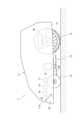
図1は、本実施形態に係る無人芝刈システム1の構成を示す図である。
無人芝刈システム1は、ロボット芝刈機2と、芝刈作業を実行する作業対象エリアである芝刈エリアARを区画するエリアワイヤー5と、充電ステーション3と、を備える。
ロボット芝刈機2は、芝刈エリアARの中を無人で自律走行しながら芝草を刈る自律走行作業機である。エリアワイヤー5は、芝刈エリアARの境界Aをロボット芝刈機2が検知可能にするために、業者等によって境界Aに沿って敷設される部材である。本実施形態では、敷設されたエリアワイヤー5が磁性を帯びており、ロボット芝刈機2がエリアワイヤー5の磁気を検出することで芝刈エリアARの境界Aを検知する。ロボット芝刈機2は、「自律走行作業機」の一例に対応する。Embodiments of the present invention will be described below with reference to the drawings.
FIG. 1 is a diagram showing the configuration of an unmanned
The unmanned
The
充電ステーション3は、ロボット芝刈機2が備えるバッテリー17(図2)を無線給電によって充電する装置であり、芝刈エリアARの中に設置される。充電ステーション3は、非作業時におけるロボット芝刈機2の待機場所でもある。ロボット芝刈機2は、芝刈作業の終了時、或いは、バッテリー17の残量が少なくなった場合(残量が所定値を下回った場合)に、自律走行により充電ステーション3に帰還し、充電ステーション3から充電を受けるように構成されている。 The
図2は、ロボット芝刈機2の構成を示す図である。
ロボット芝刈機2は、本体ケースを構成するハウジング11と、ハウジング11の前部の左右の各々に設けられた前輪12と、ハウジング11の後部の左右の各々に設けられた後輪13と、ハウジング11の中央の下部に設けられた作業部14とを備えている。作業部14は、芝草を刈る刈刃が設けられた刈刃ディスク14Aを有する。FIG. 2 is a diagram showing the configuration of the
The
ロボット芝刈機2は、左右の各後輪13を個別に駆動する走行用モーター15と、作業部14の刈刃ディスク14Aを駆動する作業部駆動用モーター16と、バッテリー17と、充電制御回路18と、制御部20と、を備え、これらがハウジング11に収納されている。 The
制御部20は、ロボット芝刈機2の各部を制御するものであり、CPUやMPU等のプロセッサプロセッサーと、RAMやROM等のメモリデバイスと、を有する。プロセッサがメモリデバイスに格納されたプログラムを実行することで、制御部20は、走行用モーター15を制御して自律走行する自律走行制御や、作業部駆動用モーター16を制御して芝刈動作する芝刈動作制御などの各種の制御手段として機能する。またメモリデバイスには、芝刈エリアARに関するマップデータや、芝刈作業の自動実行スケジュールを示すスケジュールデータといった、自律走行制御や芝刈作業制御に要する各種のデータが格納されている。 The
バッテリー17は、ロボット芝刈機2の各部に電力を供給するものであり、充電制御回路18は、充電ステーション3から給電される電力でバッテリー17を充電する。
本実施形態では、充電ステーション3とロボット芝刈機2とによって、充電ステーション3からロボット芝刈機2に電力を無線給電する無線給電システム30が構成されている。かかる無線給電システム30によれば、受電のために充電ステーション3に機械的に係合する電極をロボット芝刈機2に設ける必要がないため、ロボット芝刈機2の防水性、防塵性、及び絶縁性を向上させることができる。またロボット芝刈機2において、受電のための電極(後述する受電コイル35)をハウジング11の中に配置し、当該電極を露出させない事で、ロボット芝刈機2の安全性や耐久性、デザイン性の向上を図ることができる。The
In this embodiment, the
かかる無線給電システム30について図3を参照して、より詳述に説明する。 The wireless
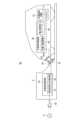
図3は、無線給電システム30の構成を示す図である。
無線給電システム30は、電磁誘導を利用して非接触に電力を送受するシステムであり、図3に示すように、充電ステーション3が、非接触送電回路32と、送電コイル33と、コア34と、を備え、ロボット芝刈機2が、受電コイル35と、非接触受電回路36と、を備える。
非接触送電回路32は、電源コード40を介して商用電源Pに接続され、当該商用電源Pの商用電力を送電コイル33から送電する回路であり、商用電力を送電電力に変換する電源回路41と、送電電力に応じた所定周波数の交流電圧(交流電流)を送電コイル33に出力する送電回路42と、を備える。送電コイル33は電力供給用のコイルである。コア34は、磁性体材料から成る柱状の部材であり、当該送電コイル33がコア34に挿入状態で設けられている。FIG. 3 is a diagram showing the configuration of the wireless
The wireless
The contactless
受電コイル35は電力取出用のコイルであり、交流電流によって交番磁界を発する送電コイル33と磁気結合し、電磁誘導によって誘導起電力を発生させることで、送電コイル33から電力を受け取る。
本実施形態の無線給電システム30では、バッテリー17の充電時には、受電コイル35にコア34の先端34Aが挿入された状態で無線給電が行われることで、送電コイル33と受電コイル35との間の磁気的な結合が強められ、送電コイル33、及び受電コイル35の間のエネルギー伝達効率が高められている。The
In the wireless
非接触受電回路36は、受電コイル35に生じた誘導起電力から充電電力を生成するものであり、共振・整流回路43と、電圧調整用コンバータ44と、を備える。共振・整流回路43は、受電コイル35を送電コイル33の交番磁界(交流電流)と共振させることで当該受電コイル35に正弦波の電流を生じさせ、当該電流を整流することで直流電圧を出力する回路である。電圧調整用コンバータ44は、共振・整流回路43が出力する直流電圧を、充電に用いる所定電圧値の直流電圧に変換し、それを出力する回路である。上記充電制御回路18によって、かかる直流電圧がバッテリー17に印加されることで、当該バッテリー17が充電される。 The non-contact
なお、無線給電システム30において、送電コイル33や、コア34、受電コイル35の材質、及び、それらの構造(寸法形状など)は、所望の電力が無線給電可能なものであれば任意である。 In the wireless
ここで、電磁誘導方式の無線給電システム30においては、非接触でエネルギーを伝達する距離(すなわち、送電コイル33及び受電コイル35の間の距離)が長くなるほど、同じ電力を送受するためには、これら送電コイル33、受電コイル35の直径を大きくし、かつ、コア34を大型化する必要がある。このため、コア34は、比較的大型化し、重量物になる傾向がある。
これに対し、上述の通り、この無線給電システム30では、コア34が充電ステーション3の側に設けられ、このコア34に、ロボット芝刈機2の受電コイル35を挿入する構成となっている。これにより、ロボット芝刈機2の重量増加が抑えられ、ロボット芝刈機2の可搬性(ユーザによる持ち運び)が損なわれたり、轍が芝生に残り易くなったりする、といった悪影響が抑えられる。また、ユーザーによって持ち運ばれるロボット芝刈機2の側にコア34が設けられていないため、比較的割れ易いコア34の破損を抑制できる。Here, in the electromagnetic induction type wireless
On the other hand, as described above, in this wireless
図4は、充電ステーション3、及びロボット芝刈機2の係合構造の説明図である。
同図に示すように、充電ステーション3は、上記送電コイル33、コア34、及び、これらを覆う送電カバー51を備えた送電用構造体50を有する。
充電ステーション3は、ロボット芝刈機2に対面する壁面52を有し、この壁面52に送電用構造体50が設けられる。具体的には、柱状のコア34が壁面52に突設され、そのコア34に送電コイル33が挿入され、これらコア34、及び送電コイル33が送電カバー51で覆われている。送電カバー51は、凸状(本実施形態では四角柱状)の凸部53を有し、この凸部53の中にコア34が配置される。なお、壁面52や送電カバー51の材料は、無線給電を阻害しない限り任意である。FIG. 4 is an explanatory diagram of the engagement structure of the charging
As shown in the figure, the charging
The charging
図5は、ロボット芝刈機2の前面11Aの構成を模試的に示す図である。
ロボット芝刈機2のハウジング11の前面11Aには、充電時に充電ステーション3の壁面52に対面する箇所に、送電カバー51の凸部53と係合する凹部55が設けられている。同図5、及び前掲図4に示すように、受電コイル35は、この凹部55を包囲するようにハウジング11の中に設けられており、充電ステーション3の凸部53が凹部55に入り込むことで、凸部53の中のコア34が受電コイル35に挿入された状態となる。
なお、受電コイル35をハウジング11の中にどのように設置するかは任意であり、例えば樹脂製のハウジング11の凹部55に受電コイル35を埋設してもよいし、ハウジング11の内面に設けた保持構造によって受電コイル35を保持してもよい。FIG. 5 is a schematic diagram showing the configuration of the
The
It should be noted that how the
本実施形態の凹部55は、同図5に示すように、前面11Aの正面視において左側の左側面55L、及び右側の右側面55Rが凸部53に係合し、また底面55Bが凸部53の先端53A(図4)に突き当たることで、充電ステーション3の凸部53と、ロボット芝刈機2の凹部55との相対位置を一意の位置に位置決めするように構成されている。かかる凸部53と凹部55の係合構造により、送電コイル33、及び受電コイル35の相対位置が、効率良くエネルギー伝達が行われる位置に位置決めされる。 As shown in FIG. 5, in the front view of the
なお、凸部53、及び凹部55の係合面(例えば上記左側面55L、及び右側面55R)をテーパー形状にすることで、ロボット芝刈機2が充電ステーション3に帰還する際に凸部53、及び凹部55が係合し易いようにしてもよい。
またロボット芝刈機2は、自走して充電ステーション3に帰還する際、受電コイル35によって所定値以上の電圧が受電されているか否かを判定することで、凸部53と凹部55とが適切に係合したか否かを判定することもできる。By tapering the engagement surfaces of the
Further, when the
図6は、送電コイル33、コア34、及び受電コイル35の係合関係の説明図である。
ロボット芝刈機2の受電コイル35が、充電ステーション3の凸部53(コア34)に挿入されるためには、図6(A)に示すように、受電コイル35がコア34の先端34Aよりも低い位置に配置されている必要がある。
しかしながら、図6(A)の構成においては、ロボット芝刈機2が進入方向Dに直進して充電ステーション3に進入する際に、仮想線で示すように受電コイル35がコア34に衝突し、ロボット芝刈機2の進入が阻害される。FIG. 6 is an explanatory diagram of the engagement relationship between the
In order for the
However, in the configuration of FIG. 6(A), when the
そこで、本実施形態では、受電コイル35には、ロボット芝刈機2が充電ステーション3に進入する際にコア34を通す開放部70が設けられている。
具体的には、図6(B)、及び前掲図4に示すように、受電コイル35のうち、ロボット芝刈機2が充電ステーション3に進入する際にコア34に対向する前端部60Aを、コア34の先端34Aよりも高い位置に配置することで、コア34が通過する開放部70が当該前端部60Aの下方に形成される。
さらに、受電コイル35は、コア34の先端34Aよりも低い位置に配置された低位部60Lを有することで、開放部70を通過して受電コイル35の内部に進入したコア34の先端34Aが当該受電コイル35から突出するようになっている。本実施形態において低位部60Lは、受電コイル35のうち、前端部60Aに対向する後端部60Bを含む範囲に設定されており、この受電コイル35では、当該後端部60Bが最も低くなっている。かかる開放部70、及び低位部60Lを有した受電コイル35は、コア34の先端34Aよりも低い位置に後端部60Bを配置した状態で、当該後端部60Bを基点とし、前端部60Aをコア34の先端34Aよりも高い地点に配置する傾斜角度で、受電コイル35を傾斜させることで実現される。Therefore, in the present embodiment, the receiving
Specifically, as shown in FIG. 6B and FIG. 4, the
Further, the receiving
また前掲図3、及び図4に示すように、本実施形態では、コア34が地面(すなわち、ロボット芝刈機2の進行方向)に対して斜めに立設されている。これにより、垂直に立設された場合に比べ、コア34の先端34Aの高さを低くできる。 As shown in FIGS. 3 and 4, in this embodiment, the core 34 stands obliquely with respect to the ground (that is, the traveling direction of the robot lawnmower 2). As a result, the height of the
上述した実施形態によれば、次のような効果を奏する。 According to the embodiment described above, the following effects are obtained.
本実施形態では、ロボット芝刈機2の受電コイル35は、当該ロボット芝刈機2が充電ステーション3に進入する際にコア34が通過する開放部70を有する。これにより、ロボット芝刈機2の進入時に、受電コイル35がコア34に衝突することなく、受電コイル35の中に当該コア34を容易に配置できる。 In this embodiment, the receiving
本実施形態では、受電コイル35は、ロボット芝刈機2が充電ステーション3に進入する際にコア34に対向する前端部60Aが、当該コア34の先端34Aよりも高い位置に配置されることで、当該前端部60Aの下方に開放部70が形成されている。
これにより、開放部70を受電コイル35に簡単に設けることができる。In this embodiment, the
Thereby, the opening
本実施形態では、受電コイル35は、コア34の先端よりも低い位置に配置された低位部60Lを有するので、コア34の先端34Aを受電コイル35(低位部60L)から突出させ、受電コイル35がコア34に挿入された状態を簡単に作ることができる。 In the present embodiment, the
本実施形態では、受電コイル35の低位部60Lは、前端部60Aに対向する後端部60Bを含む範囲に設けられているので、例えば、コア34の先端34Aよりも低い位置に後端部60Bを配置した状態で、当該後端部60Bを基点とし、前端部60Aをコア34の先端34Aよりも高い地点に配置する傾斜角度で、受電コイル35を傾斜させることで、上記開放部70、及び低位部60Lを有した受電コイル35を簡単に実現できる。 In the present embodiment, the
本実施形態では、充電ステーション3には送電コイル33を覆う送電カバー51が設けられており、ロボット芝刈機2は、充電ステーション3に進入する際に送電カバー51に係合する係合部としての凹部55を有する。
これにより、送電カバー51と、凹部55との係合構造により、充電ステーション3の凸部53と、ロボット芝刈機2の凹部55との相対位置を、効率良くエネルギー伝達が行われる位置に、簡単に位置決めできる。In this embodiment, the charging
As a result, the engagement structure between the
本実施形態では、受電コイル35は、送電カバー51の凸部53に係合する凹部55を囲んで設けられている。これにより、充電ステーション3の凸部53に、ロボット芝刈機2の凹部55が係合すれば、凸部53に収められたコア34が受電コイル35に挿入された状態になる。したがって、例えばユーザーがロボット芝刈機2を充電ステーション3にセットする際には、受電コイル35やコア34が目視できなくとも、凸部53、及び凹部55を係合させるだけで、簡単、かつ確実に、受電コイル35をコア34に挿入することができる。 In the present embodiment, the
なお、上述した実施形態は、あくまでも本発明の一態様の例示であり、本発明の主旨を逸脱しない範囲において任意に変形、及び応用が可能である。 Note that the above-described embodiment is merely an example of one aspect of the present invention, and can be arbitrarily modified and applied without departing from the gist of the present invention.
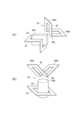
上述した実施形態において、例えば図7(A)に示すように、受電コイル35の前端部60Aをコア34の先端34Aよりも高い位置に配置した状態で、後端部60Bの側を略L字状に折り曲げるとで、前端部60Aの下方に開放部70を設け、かつ当該後端部60Bの側に低位部60Lを設けてもよい。また、この場合、送電コイル33を受電コイル35の屈曲に合わせてL字状に折り曲げてもよい。 In the above-described embodiment, for example, as shown in FIG. 7A, the
また例えば、コア34は地面に傾斜して設ける構成に限らず、図7(B)に示すように、地面に略垂直に立設してもよい。
また同図7(B)に示すように、受電コイル35において、前端部60A、及び後端部60Bをコア34の先端34Aよりも高い位置に配置した状態で、これら前端部60A、及び後端部60Bの間(図示例では中間部)に低位部60Lを設けてもよい。この構成によれば、後端部60Bの下方にも、コア34が通過可能な開放部70を形成できる。Further, for example, the
Further, as shown in FIG. 7B, in the receiving
また例えば図7(C)に示すように、受電コイル35において、前端部60Aをコア34の先端34Aよりも高い位置に配置した状態で、後端部60Bから前端部60Aにかけた所定の範囲Wを低位部60Lとしてもよい。 Further, for example, as shown in FIG. 7C, in a state where the
また例えば、コア34は、円柱や四角柱などの柱状に限らず、例えば図8(A)に示すように、板状であってもよい。この場合、コア34の先端34Aは、最も高い位置にある面、或いは部位(図示例では上面)に該当する。 Further, for example, the
また例えば、充電時には、コア34が受電コイル35に挿入されてなくとも良く、例えば、図8(B)に示すように、受電コイル35の全体がコア34の先端34Aよりも高い位置に配置されていてもよい。ただし、この場合、送電コイル33との磁気結合を強めるために、受電コイル35には、同図に示すように、前端部60Aを除くいずれかの箇所(図示例では、前端部60Aと後端部60Bの中間部)に、コア34の先端34Aに近づく部位80を設けることが望ましい。 Further, for example, during charging, the
上述した実施形態において、ロボット芝刈機2が備えるバッテリー17と、受電コイル35とを1つのパッケージに収めることで、これらをユーザーが交換自在にしてもよい。このパッケージには、重量物である上記コア34が含まれることは無いので、パッケージの取扱性を高めることができる。 In the above-described embodiment, the
本発明は、ロボット芝刈機2に限らず、バッテリー17を搭載し、自律走行しながら作業を行う任意の自律走行作業機に適用できる。 The present invention is not limited to the
上述した実施形態において、水平、及び垂直等の方向、及び形状は、特段の断りがなされていない限り、これらの方向の周辺の範囲、及び、近似の形状を除外するものではなく、同一の作用効果を奏する限りにおいて、これら周辺の範囲、及び近似の形状(いわゆる、均等の範囲)を含む。 In the above-described embodiments, directions such as horizontal and vertical, and shapes do not exclude ranges around these directions and approximate shapes, and have the same effect, unless otherwise specified. To the extent efficacious, these peripheral ranges and approximate shapes (so-called equivalent ranges) are included.
1 無人芝刈システム
2 ロボット芝刈機(自律走行作業機)
3 充電ステーション(ステーション)
17 バッテリー
30 無線給電システム
32 非接触送電回路
33 送電コイル
34 コア
34A コアの先端
35 受電コイル
36 非接触受電回路
50 送電用構造体
51 送電カバー
53 凸部
53A 凸部の先端
55 凹部
60A 受電コイルの前端部
60B 受電コイルの後端部
60L 低位部
70 開放部
D 進入方向1 Unmanned
3 Charging station (station)
17
Claims (6)
Translated fromJapanese前記ステーションに設けられ、地面に対して斜めに配置される磁性体のコアが挿入された送電コイルに磁気結合する受電コイルを有し、
前記受電コイルは、
前記自律走行作業機が前記ステーションに進入する際に前方に位置する前端部と、後方に位置する後端部とを有し、前記前端部を上にして傾けて前記自律走行作業機に固定され、前記前端部の下方に前記コアが通過する開放部が形成され、前記後端部は前記開放部に前記コアの先端が挿入された際に当該コアの先端よりも低い位置に配置される低位部を有する
ことを特徴とする自律走行作業機。An autonomous traveling work machine that receives wireless power supply from a station,
A power receiving coil that is provided in the station and magnetically couples to a power transmitting coil in which a magnetic core isinserted and arranged obliquely with respect to the ground ;
The receiving coil is
When the autonomous traveling work machine enters the station, it has a front end positioned forward and a rear end positioned rearward, and is fixed to the autonomous traveling work machine with the front end tilted upward. , an opening through which the core passes is formed below the front end, and the rear end is arranged at a position lower than the tip of the core when the tip of the core is inserted into the opening. have a part
An autonomous traveling work machine characterized by:
前記ステーションに設けられ、地面に対して斜め又は地面に略垂直に配置される磁性体のコアが挿入された送電コイルに磁気結合する受電コイルを有し、
前記受電コイルは、
前記自律走行作業機が前記ステーションに進入する際に前方に位置する前端部と、後方に位置する後端部とを有し、前記後端部と前記前端部との間を折り曲げて前記自律走行作業機に固定され、前記前端部の下方に前記コアが通過する開放部が形成され、前記折り曲げた部分は前記開放部に前記コアの先端が挿入された際に当該コアの先端よりも低い位置に配置される低位部を有する
ことを特徴とする自律走行作業機。An autonomous traveling work machine that receives wireless power supply from a station,
A power receiving coil that is provided in the station and magnetically couples to a power transmitting coil in which a magnetic core is insertedthat is arranged obliquely to the ground or substantially perpendicular to the ground ;
The receiving coil is
Whenthe autonomous traveling work machine enters the station, it has a front end positioned forward and a rear end positioned rearward, and the autonomous traveling work machine is bent between the rear end and the front end. Fixed to the work machine, an opening through which the core passes is formed below the front end, and the bent portion is positioned lower than the tip of the core when the tip of the core is inserted into the opening. having a lower portion located in
An autonomous traveling work machine characterized by:
前記自律走行作業機は、
前記ステーションに進入する際に前記送電カバーに係合する係合部を有する
ことを特徴とする請求項1又は2に記載の自律走行作業機。The station is provided with a power transmission cover that covers the power transmission coil,
The autonomous traveling work machine includes:
The autonomous traveling work machine according to claim 1 or 2, further comprising an engaging portion that engages with the power transmission cover when entering the station.
前記係合部は、前記凸部に係合する凹部を有し、
前記受電コイルは、当該凹部を囲んで設けられている
ことを特徴とする請求項3に記載の自律走行作業機。The power transmission cover has a convex portion containing the core,
The engaging portion has a concave portion that engages with the convex portion,
The autonomous traveling work machine according to claim 3, wherein the power receiving coil is provided so as to surround the recess.
前記ステーションから無線給電を受ける自律走行作業機と、を備えた無線給電システムであって、
前記ステーションは、
送電コイル、及び当該送電コイルが挿入され、地面に対して斜めに配置される磁性体のコアを有し、
前記自律走行作業機は、
前記送電コイルと磁気結合する受電コイルを有し、
前記受電コイルは、
前記自律走行作業機が前記ステーションに進入する際に前方に位置する前端部と、後方に位置する後端部とを有し、前記前端部を上にして傾けて前記自律走行作業機に固定され、前記前端部の下方に前記コアが通過する開放部が形成され、前記後端部は前記開放部に前記コアの先端が挿入された際に当該コアの先端よりも低い位置に配置される低位部を有する
ことを特徴とする無線給電システム。a station;
A wireless power supply system comprising: an autonomous mobile work machine that receives wireless power supply from the station,
The station is
A power transmission coil and a magnetic core into which the power transmission coil is insertedand arranged obliquely with respect to the ground ,
The autonomous traveling work machine includes:
Having a power receiving coil that magnetically couples with the power transmitting coil,
The receiving coil is
When the autonomous traveling work machine enters the station, it has a front end positioned forward and a rear end positioned rearward, and is fixed to the autonomous traveling work machine with the front end tilted upward. , an opening through which the core passes is formed below the front end, and the rear end is arranged at a position lower than the tip of the core when the tip of the core is inserted into the opening. have a part
A wireless power supply system characterized by:
前記ステーションから無線給電を受ける自律走行作業機と、を備えた無線給電システムであって、
前記ステーションは、
送電コイル、及び当該送電コイルが挿入され、地面に対して斜め又は地面に略垂直に配置される磁性体のコアを有し、
前記自律走行作業機は、
前記送電コイルと磁気結合する受電コイルを有し、
前記受電コイルは、
前記自律走行作業機が前記ステーションに進入する際に前方に位置する前端部と、後方に位置する後端部とを有し、前記後端部と前記前端部との間を折り曲げて前記自律走行作業機に固定され、前記前端部の下方に前記コアが通過する開放部が形成され、前記折り曲げた部分は前記開放部に前記コアの先端が挿入された際に当該コアの先端よりも低い位置に配置される低位部を有する
ことを特徴とする無線給電システム。
a station;
A wireless power supply system comprising: an autonomous mobile work machine that receives wireless power supply from the station,
The station is
a power transmission coil, and a magnetic core into which the power transmission coil is insertedand arranged obliquely to the ground or substantially perpendicular to the ground ;
The autonomous traveling work machine includes:
Having a power receiving coil that magnetically couples with the power transmitting coil,
The receiving coil is
Whenthe autonomous traveling work machine enters the station, it has a front end positioned forward and a rear end positioned rearward, and the autonomous traveling work machine is bent between the rear end and the front end. Fixed to the work machine, an opening through which the core passes is formed below the front end, and the bent portion is positioned lower than the tip of the core when the tip of the core is inserted into the opening. having a lower portion located in
A wireless power supply system characterized by:
Priority Applications (3)
| Application Number | Priority Date | Filing Date | Title |
|---|---|---|---|
| JP2019111489AJP7260409B2 (en) | 2019-06-14 | 2019-06-14 | Autonomous working machine and wireless power supply system |
| EP20172673.4AEP3751700B1 (en) | 2019-06-14 | 2020-05-04 | Autonomous running working machine and wireless power feeding system |
| US15/931,953US11205925B2 (en) | 2019-06-14 | 2020-05-14 | Wireless power feeding structure including a power transmission coil, power reception coil, and a core of a magnetic substance |
Applications Claiming Priority (1)
| Application Number | Priority Date | Filing Date | Title |
|---|---|---|---|
| JP2019111489AJP7260409B2 (en) | 2019-06-14 | 2019-06-14 | Autonomous working machine and wireless power supply system |
Publications (2)
| Publication Number | Publication Date |
|---|---|
| JP2020205680A JP2020205680A (en) | 2020-12-24 |
| JP7260409B2true JP7260409B2 (en) | 2023-04-18 |
Family
ID=70553728
Family Applications (1)
| Application Number | Title | Priority Date | Filing Date |
|---|---|---|---|
| JP2019111489AActiveJP7260409B2 (en) | 2019-06-14 | 2019-06-14 | Autonomous working machine and wireless power supply system |
Country Status (3)
| Country | Link |
|---|---|
| US (1) | US11205925B2 (en) |
| EP (1) | EP3751700B1 (en) |
| JP (1) | JP7260409B2 (en) |
Families Citing this family (1)
| Publication number | Priority date | Publication date | Assignee | Title |
|---|---|---|---|---|
| JP2023009634A (en)* | 2021-07-07 | 2023-01-20 | 株式会社マキタ | Reinforcement binding robot |
Citations (6)
| Publication number | Priority date | Publication date | Assignee | Title |
|---|---|---|---|---|
| JP2010080851A (en) | 2008-09-29 | 2010-04-08 | Canon Inc | Power receiving coil and electronic equipment |
| WO2013080860A1 (en) | 2011-11-28 | 2013-06-06 | 株式会社 豊田自動織機 | Non-contact power supply device |
| JP2014197977A (en) | 2013-03-08 | 2014-10-16 | Tdk株式会社 | Power supply device, power reception device and wireless power transmission device |
| JP2015092809A (en) | 2013-10-04 | 2015-05-14 | Tdk株式会社 | Power receiving device and power supply device |
| JP2016010382A (en) | 2014-06-30 | 2016-01-21 | 日立工機株式会社 | Self-propelled mower |
| US20170215336A1 (en) | 2014-08-07 | 2017-08-03 | Positec Power Tools (Suzhou) Co., Ltd. | Wireless charging station, automatic mower and automatic mowing system |
Family Cites Families (22)
| Publication number | Priority date | Publication date | Assignee | Title |
|---|---|---|---|---|
| EP0552737A1 (en)* | 1992-01-22 | 1993-07-28 | Hughes Aircraft Company | Weatherized curb-side charger |
| JPH06189479A (en)* | 1992-12-15 | 1994-07-08 | Toyota Autom Loom Works Ltd | Electromagnetic power feeding apparatus |
| US5408209A (en)* | 1993-11-02 | 1995-04-18 | Hughes Aircraft Company | Cooled secondary coils of electric automobile charging transformer |
| JP3185605B2 (en)* | 1995-05-29 | 2001-07-11 | 松下電器産業株式会社 | DC power supply |
| WO1996038898A1 (en)* | 1995-05-29 | 1996-12-05 | Matsushita Electric Industrial Co., Ltd. | Power source apparatus |
| JPH09102429A (en)* | 1995-07-31 | 1997-04-15 | Sumitomo Wiring Syst Ltd | Charging device for electric automobile |
| EP0788211B1 (en)* | 1996-01-30 | 2002-08-28 | Sumitomo Wiring Systems, Ltd. | A connection system and a connection method |
| JPH1075538A (en)* | 1996-06-27 | 1998-03-17 | Sumitomo Wiring Syst Ltd | Charging connector |
| JPH10322921A (en)* | 1997-05-15 | 1998-12-04 | Sumitomo Wiring Syst Ltd | Magnetic coupling device for electric vehicle charging |
| JPH11285156A (en)* | 1998-03-30 | 1999-10-15 | Nippon Electric Ind Co Ltd | Non-contact charger |
| DE102009059976A1 (en)* | 2009-12-22 | 2011-06-30 | HS Genion GmbH, 82205 | System for charging a battery of a motor vehicle |
| JP5593977B2 (en) | 2010-09-01 | 2014-09-24 | Nok株式会社 | Non-contact power feeding device |
| EP2621050B1 (en)* | 2012-01-27 | 2015-04-08 | Braun GmbH | Inductive Charger for Hand-Held Appliances |
| JP5859869B2 (en)* | 2012-02-10 | 2016-02-16 | 本田技研工業株式会社 | lawn mower |
| US9240276B2 (en)* | 2012-11-27 | 2016-01-19 | GM Global Technology Operations LLC | Induction powered panels |
| KR101449197B1 (en)* | 2012-12-26 | 2014-10-08 | 현대자동차주식회사 | Magnetic connector apparatus for charging electric vehicle |
| US9805864B2 (en)* | 2014-04-04 | 2017-10-31 | Apple Inc. | Inductive spring system |
| JP6129231B2 (en)* | 2015-03-27 | 2017-05-17 | 本田技研工業株式会社 | Lawn mower |
| JP2017010161A (en) | 2015-06-18 | 2017-01-12 | 本田技研工業株式会社 | Control device for unmanned working machine |
| CN108366532B (en)* | 2015-12-24 | 2021-01-08 | 本田技研工业株式会社 | Automatic traveling mower |
| JP6141956B1 (en)* | 2015-12-25 | 2017-06-07 | 本田技研工業株式会社 | Automatic lawn mower |
| DE112018001471T5 (en)* | 2017-03-22 | 2019-12-05 | The University Of Hong Kong | System and method for charging electric vehicles |
- 2019
- 2019-06-14JPJP2019111489Apatent/JP7260409B2/enactiveActive
- 2020
- 2020-05-04EPEP20172673.4Apatent/EP3751700B1/enactiveActive
- 2020-05-14USUS15/931,953patent/US11205925B2/enactiveActive
Patent Citations (6)
| Publication number | Priority date | Publication date | Assignee | Title |
|---|---|---|---|---|
| JP2010080851A (en) | 2008-09-29 | 2010-04-08 | Canon Inc | Power receiving coil and electronic equipment |
| WO2013080860A1 (en) | 2011-11-28 | 2013-06-06 | 株式会社 豊田自動織機 | Non-contact power supply device |
| JP2014197977A (en) | 2013-03-08 | 2014-10-16 | Tdk株式会社 | Power supply device, power reception device and wireless power transmission device |
| JP2015092809A (en) | 2013-10-04 | 2015-05-14 | Tdk株式会社 | Power receiving device and power supply device |
| JP2016010382A (en) | 2014-06-30 | 2016-01-21 | 日立工機株式会社 | Self-propelled mower |
| US20170215336A1 (en) | 2014-08-07 | 2017-08-03 | Positec Power Tools (Suzhou) Co., Ltd. | Wireless charging station, automatic mower and automatic mowing system |
Also Published As
| Publication number | Publication date |
|---|---|
| JP2020205680A (en) | 2020-12-24 |
| US11205925B2 (en) | 2021-12-21 |
| US20200395786A1 (en) | 2020-12-17 |
| EP3751700A1 (en) | 2020-12-16 |
| EP3751700B1 (en) | 2022-06-08 |
Similar Documents
| Publication | Publication Date | Title |
|---|---|---|
| CN114815839B (en) | System and method for docking a robotic lawn mower | |
| US10575696B2 (en) | Autonomous robot auto-docking and energy management systems and methods | |
| JP5860998B2 (en) | System and method for guiding a robot cleaner along a path | |
| CN103948354B (en) | A kind of robot for cleaning floor and control method thereof | |
| JPWO2013175596A1 (en) | Power transmission system and method, power transmission device and power reception device | |
| US11906975B2 (en) | Mobile charging apparatus | |
| JP2016010382A (en) | Self-propelled mower | |
| CN111602315A (en) | Wireless charging station, self-moving equipment and wireless charging system | |
| CN104737698A (en) | Automatic lawn mower | |
| WO2017101882A1 (en) | Auto-movement robot system | |
| JP7260409B2 (en) | Autonomous working machine and wireless power supply system | |
| JP7260672B2 (en) | Autonomous working machine station and power supply | |
| CN119225356A (en) | Autonomous charging system, autonomous mobile device and charging station | |
| EP4254117B1 (en) | Self-moving robot charging systems and self-moving robot charging method | |
| US20210066933A1 (en) | Charging control system, autonomous traveling work machine, and charging station | |
| CN112352367A (en) | Non-contact power supply system for vehicle | |
| JP6006857B2 (en) | Power transmission equipment | |
| EP2679083A1 (en) | Apparatus for cutting grass | |
| JP2016103938A (en) | Vehicle power supply equipment | |
| KR102023342B1 (en) | Wireless Power Charging System Strong to Deviation | |
| CN114518747A (en) | A kind of robot return charging control method and device | |
| CN216099032U (en) | Line patrol sensor and robot | |
| TWI595728B (en) | Robot having rechargable function, wireless charging device and wireless charging system | |
| CN223428178U (en) | A docking station, autonomous operating equipment, boundary of autonomous operating equipment, and autonomous operating system | |
| US12325317B2 (en) | Autonomous work system and autonomous work machine |
Legal Events
| Date | Code | Title | Description |
|---|---|---|---|
| A621 | Written request for application examination | Free format text:JAPANESE INTERMEDIATE CODE: A621 Effective date:20211126 | |
| A977 | Report on retrieval | Free format text:JAPANESE INTERMEDIATE CODE: A971007 Effective date:20220926 | |
| A131 | Notification of reasons for refusal | Free format text:JAPANESE INTERMEDIATE CODE: A131 Effective date:20221004 | |
| A521 | Request for written amendment filed | Free format text:JAPANESE INTERMEDIATE CODE: A523 Effective date:20221202 | |
| TRDD | Decision of grant or rejection written | ||
| A01 | Written decision to grant a patent or to grant a registration (utility model) | Free format text:JAPANESE INTERMEDIATE CODE: A01 Effective date:20230328 | |
| A61 | First payment of annual fees (during grant procedure) | Free format text:JAPANESE INTERMEDIATE CODE: A61 Effective date:20230406 | |
| R150 | Certificate of patent or registration of utility model | Ref document number:7260409 Country of ref document:JP Free format text:JAPANESE INTERMEDIATE CODE: R150 |