Movatterモバイル変換


[0]ホーム

URL:


JP7259489B2 - cassette - Google Patents

cassette
Download PDF

Info

Publication number
JP7259489B2
JP7259489B2JP2019069561AJP2019069561AJP7259489B2JP 7259489 B2JP7259489 B2JP 7259489B2JP 2019069561 AJP2019069561 AJP 2019069561AJP 2019069561 AJP2019069561 AJP 2019069561AJP 7259489 B2JP7259489 B2JP 7259489B2
Authority
JP
Japan
Prior art keywords
printing tape
cassette
spool
printing
recess
Prior art date
Legal status (The legal status is an assumption and is not a legal conclusion. Google has not performed a legal analysis and makes no representation as to the accuracy of the status listed.)
Active
Application number
JP2019069561A
Other languages
Japanese (ja)
Other versions
JP2020168725A (en
Inventor
健太郎 村山
Current Assignee (The listed assignees may be inaccurate. Google has not performed a legal analysis and makes no representation or warranty as to the accuracy of the list.)
Brother Industries Ltd
Original Assignee
Brother Industries Ltd
Priority date (The priority date is an assumption and is not a legal conclusion. Google has not performed a legal analysis and makes no representation as to the accuracy of the date listed.)
Filing date
Publication date
Priority to JP2019069561ApriorityCriticalpatent/JP7259489B2/en
Application filed by Brother Industries LtdfiledCriticalBrother Industries Ltd
Priority to CN202310903332.XAprioritypatent/CN117021793B/en
Priority to CA3135338Aprioritypatent/CA3135338A1/en
Priority to MX2021011978Aprioritypatent/MX2021011978A/en
Priority to PH1/2021/552450Aprioritypatent/PH12021552450A1/en
Priority to CN202310903324.5Aprioritypatent/CN117021792B/en
Priority to CN202080026096.2Aprioritypatent/CN113661069B/en
Priority to SG11202110838RAprioritypatent/SG11202110838RA/en
Priority to KR1020257018658Aprioritypatent/KR20250090369A/en
Priority to EP20783843.4Aprioritypatent/EP3932681A4/en
Priority to AU2020250328Aprioritypatent/AU2020250328B2/en
Priority to KR1020217031344Aprioritypatent/KR102819117B1/en
Priority to CN202310903311.8Aprioritypatent/CN117021791A/en
Priority to BR112021019447Aprioritypatent/BR112021019447A2/en
Priority to PCT/JP2020/011087prioritypatent/WO2020203172A1/en
Publication of JP2020168725ApublicationCriticalpatent/JP2020168725A/en
Priority to US17/489,713prioritypatent/US11987064B2/en
Priority to MX2025001517Aprioritypatent/MX2025001517A/en
Priority to JP2023060616Aprioritypatent/JP7452735B2/en
Application grantedgrantedCritical
Publication of JP7259489B2publicationCriticalpatent/JP7259489B2/en
Priority to JP2024032546Aprioritypatent/JP7647956B2/en
Priority to US18/631,331prioritypatent/US20240253378A1/en
Priority to JP2025035278Aprioritypatent/JP2025074346A/en
Activelegal-statusCriticalCurrent
Anticipated expirationlegal-statusCritical

Links

Images

Classifications

Landscapes

Description

Translated fromJapanese

本発明は、印刷装置に脱着可能に装着されるカセットに関するものである。 The present invention relates to a cassette detachably attached to a printing apparatus.

従来、テープと、テープに印刷を行うためのインクリボンとを備えたカセットが知られている。例えば特許文献1に記載のインクリボンカートリッジは、リボンカートリッジと印刷シートカートリッジとを備える。リボンカートリッジの中には、インクリボンと、インクリボンを巻き取るための巻取軸とが収容される。印刷シートカートリッジの中には、印刷シートが収容される。印刷シートカートリッジの外周壁には、複数のセット爪が設けられる。複数のセット爪がリボンカートリッジと係合することで、印刷シートカートリッジは、リボンカートリッジの上方に重ね合わされて、リボンカートリッジと一体化される。リボンカートリッジには、プリンタのヘッドが挿入されるヘッド開口部が設けられる。印刷シートカートリッジのうち印刷シートのロールに対してヘッド開口部とは反対の位置には、印刷シートが通過するシート開口部が設けられる。印刷シートは、ロールから引き出された後、シート開口部を介して印刷シートカートリッジの外に出される。その後、印刷シートは、印刷シートカートリッジの外周壁の周りを通ってヘッド開口部を通過する。ヘッド開口部では、印刷シートとインクリボンとが互いに重ね合されて、プリンタのヘッドによって印刷が行われる。印刷された印刷シートは、ヘッド開口部側のセット爪によって、印刷シートを排出するためのフィルムゲートへ案内される。印刷に用いられたインクリボンは、巻取軸によって巻き取られる。 2. Description of the Related Art Conventionally, a cassette is known that includes a tape and an ink ribbon for printing on the tape. For example, an ink ribbon cartridge disclosed in Patent Document 1 includes a ribbon cartridge and a print sheet cartridge. The ribbon cartridge accommodates an ink ribbon and a take-up shaft for taking up the ink ribbon. A print sheet is contained within the print sheet cartridge. A plurality of setting claws are provided on the outer peripheral wall of the print sheet cartridge. By engaging the plurality of setting claws with the ribbon cartridge, the print sheet cartridge is superimposed above the ribbon cartridge and integrated with the ribbon cartridge. The ribbon cartridge is provided with a head opening into which the head of the printer is inserted. A sheet opening through which the print sheet passes is provided in the print sheet cartridge at a position opposite to the head opening with respect to the roll of the print sheet. After the print sheet is pulled from the roll, it exits the print sheet cartridge through the sheet opening. The print sheet then passes around the perimeter wall of the print sheet cartridge and through the head opening. At the head opening, the print sheet and the ink ribbon are superimposed on each other and printed by the printer head. The printed sheet is guided to a film gate for ejecting the printed sheet by a set pawl on the side of the head opening. The ink ribbon used for printing is wound up by a winding shaft.

実開昭63-156762号公報Japanese Utility Model Laid-Open No. 63-156762

上記インクリボンカートリッジは、リボンカートリッジと印刷シートカートリッジとが並ぶ方向、すなわち上下方向において異なる位置にインクリボンとヘッド開口部とを設けることで、上下方向に直交する直交方向においてカートリッジを小型化する。カセットでは、上下方向に直交する直交方向に更なる小型化が要求される。 In the ink ribbon cartridge, the ink ribbon and the head opening are provided at different positions in the direction in which the ribbon cartridge and the print sheet cartridge are arranged, that is, in the vertical direction, thereby miniaturizing the cartridge in the orthogonal direction perpendicular to the vertical direction. Cassettes are required to be further miniaturized in the orthogonal direction perpendicular to the vertical direction.

本発明は以上の事情を背景として為されたものであり、その目的とするところは、上下方向に直交する直交方向において小型化することができるカセットを提供することにある。 SUMMARY OF THE INVENTION The present invention has been made in view of the above circumstances, and an object thereof is to provide a cassette which can be miniaturized in the orthogonal direction orthogonal to the vertical direction.

第1発明の要旨とするところは、(a)印刷ヘッドを保持するヘッド保持板を有する印刷装置に装着可能なカセットであって、(b)回転可能であり、被印刷媒体である印刷テープが巻回された印刷テープロールと、()前記印刷テープロールに対して、前記印刷テープの幅方向である第1方向の一方側に位置する外周壁であって、前記第1方向に直交する第2方向に延びる第1側壁と、前記第1方向に直交し、且つ、前記第2方向と交差する第3方向に延びる第2側壁と、前記印刷ヘッドを保持する前記ヘッド保持板を収容可能であり前記第2側壁から前記第2方向の一方に延びる凹部であって前記第2側壁よりも前記第2方向の一方側において前記第3方向に延びる前記凹部を規定する凹部壁と、を備える前記外周壁と、を備え、()前記凹部の少なくとも一部は、前記印刷テープロールと前記第1方向に重なることにある。The gist of the first invention is (a)a cassette that can be mounted on a printing apparatus having a head holding plate for holding a print head, and (b) a cassette that is rotatable and has a printing tape that is a medium to be printed. a wound printing tape roll; and (c ) an outer peripheral wall positioned on one side of the printing tape roll in a first direction that is the width direction of the printing tape and that is perpendicular to the first direction. A first side wall extending in a second direction, a second side wall extending in a third direction orthogonal to the first direction and crossing the second direction, andthe head holding plate holding the print head can be accommodated. and a recessed portion extending in one of the second directions from the second side wall defining the recessed portion extending in the third direction on one side of the second direction in the second direction. and (d ) at least a portion of the recess overlaps the printing tape roll in the first direction.

第2発明の要旨とするところは、第1発明において、前記印刷テープロールは、回転可能な印刷テープスプールに前記印刷テープが巻回されてなり、前記凹部壁の少なくとも一部は、前記印刷テープスプールと前記第1方向に重なることにある。 The gist of the second invention is that in the first invention, the printing tape roll is formed by winding the printing tape around a rotatable printing tape spool, and at least a part of the wall of the recess is formed by the printing tape. It overlaps with the spool in said first direction.

第3発明の要旨とするところは、第2発明において、前記凹部の少なくとも一部は、前記印刷テープスプールと前記第1方向に重なることにある。 The gist of the third invention is that, in the second invention, at least part of the concave portion overlaps the printing tape spool in the first direction.

第4発明の要旨とするところは、第1発明から第3発明のいずれか1の発明において、前記第3方向において、前記印刷テープロールの回転中心は、前記凹部の前記第3方向の一方側端部と他方側端部との間に位置することにある。 The gist of the fourth invention is that in any one of the first to third inventions, the center of rotation of the printing tape roll in the third direction is one side of the recess in the third direction. It lies between the end and the other end.

第5発明の要旨とするところは、第1発明から第4発明のいずれか1の発明において、前記印刷テープロールは、回転可能な印刷テープスプールに前記印刷テープが巻回されてなり、前記第3方向において、前記印刷テープスプールの少なくとも一部は、前記凹部の前記第3方向の一方側端部と他方側端部との間に位置することにある。 The gist of the fifth invention is that in any one of the first to fourth inventions, the printing tape roll is formed by winding the printing tape around a rotatable printing tape spool, In three directions, at least part of the printing tape spool is positioned between one side end and the other side end of the recess in the third direction.

第6発明の要旨とするところは、第5発明において、前記第3方向において、前記印刷テープスプールの回転中心は、前記凹部の前記第3方向の前記一方側端部と前記他方側端部との間に位置することにある。 The gist of the sixth invention is that in the fifth invention, in the third direction, the center of rotation of the printing tape spool is the one end and the other end of the recess in the third direction. to be located between

第7発明の要旨とするところは、第5発明又は第6発明において、前記印刷テープロールが収容された第1ケースと、前記第1ケースに対して前記第1方向の前記一方側に位置し、前記外周壁を有する第2ケースと、を備え、前記第2ケースは、前記第2側壁により規定される排出口であって、前記第3方向において前記凹部の前記第3方向の一方側端部と他方側端部との間に位置し、前記印刷テープロールから供給される前記印刷テープが前記第2ケースから前記凹部に排出される前記排出口を備え、前記第3方向において、前記印刷テープスプールの回転中心は、前記排出口と前記凹部の前記第3方向の前記一方側端部との間に位置することにある。 The gist of the seventh invention is that, in the fifth invention or sixth invention, a first case in which the printing tape roll is housed, and and a second case having the outer peripheral wall, the second case being a discharge port defined by the second side wall, the second case being located at one end of the recess in the third direction in the third direction. and the other side end, and the discharge port through which the printing tape supplied from the printing tape roll is discharged from the second case to the recess, The rotation center of the tape spool is positioned between the discharge port and the one side end of the recess in the third direction.

第8発明の要旨とするところは、第7発明において、前記凹部は、前記第1ケースの少なくとも一部と前記第1方向に重なることにある。 The gist of the eighth invention is that in the seventh invention, the recess overlaps at least a portion of the first case in the first direction.

第9発明の要旨とするところは、第1発明から第8発明のいずれか1の発明において、前記印刷テープロールに対して前記第1方向の一方側に位置し、前記印刷テープロールから供給される前記印刷テープへの印刷に使用されるインクリボンが巻回され、回転可能な供給スプールと、前記印刷テープロールに対して前記第1方向の一方側に位置し、前記供給スプールから供給される前記インクリボンを巻き取るように回転可能な巻取スプールと、を備え、前記供給スプールの少なくとも一部及び前記巻取スプールの少なくとも一部は、前記印刷テープロールと前記第1方向に重なることにある。 The gist of the ninth invention is that in any one of the first to eighth inventions, the and a rotatable supply spool positioned on one side of the printing tape roll in the first direction and fed from the supply spool. a take-up spool rotatable to take up the ink ribbon, wherein at least a portion of the supply spool and at least a portion of the take-up spool overlap the printing tape roll in the first direction. be.

第10発明の要旨とするところは、第1発明から第9発明のいずれか1の発明において、前記印刷テープロールに対して前記第1方向の一方側に位置し、前記印刷テープに貼り合わされる貼合せテープが巻回され、回転可能な貼合せテープロールを備え、前記貼合せテープロールの少なくとも一部は、前記印刷テープロールと前記第1方向に重なることにある。 The gist of the tenth invention is that, in any one of the first to ninth inventions, the A lamination tape is wound and comprises a rotatable lamination tape roll, at least a portion of said lamination tape roll overlapping said printing tape roll in said first direction.

第11発明の要旨とするところは、第10発明において、前記貼合せテープロールは、前記貼合せテープが貼合せテープスプールに巻回されて構成され、前記貼合せテープスプールは、前記印刷テープロールと前記第1方向において重なることにある。 The gist of the eleventh invention is that in the tenth invention, the lamination tape roll is configured by winding the lamination tape around a lamination tape spool, and the lamination tape spool is configured by winding the lamination tape spool around the printing tape roll. and overlap in the first direction.

第12発明の要旨とするところは、第11発明において、前記第3方向において、前記貼合せテープスプールの回転中心は、前記凹部の前記第3方向の一方側端部と他方側端部との間に位置することにある。 The gist of the twelfth invention is that in the eleventh invention, in the third direction, the center of rotation of the lamination tape spool is between one end and the other end of the recess in the third direction. It lies in between.

第13発明の要旨とするところは、第1発明から第12発明のいずれか1の発明において、前記第2方向及び前記第3方向において、前記カセットの前記第2方向の中心且つ前記第3方向の中心である中心位置から前記印刷テープロールの回転中心までの距離は、前記中心位置から前記凹部までの距離よりも小さいことにある。 The gist of the thirteenth invention is that in any one of the first to twelfth inventions, in the second direction and the third direction, the center of the cassette in the second direction and the third direction is smaller than the distance from the center position to the recess.

第14発明の要旨とするところは、(a)印刷ヘッドを保持するヘッド保持板を有する印刷装置に装着可能なカセットであって、(b)前記印刷テープが巻回された印刷テープロールと、()前記印刷テープの幅方向である第1方向において、前記印刷テープロールに当接するスペーサフィルムと、()前記印刷テープロール及び前記スペーサフィルムに対して、前記第1方向の一方側に位置する外周壁であって、前記第1方向に直交する第2方向に延びる第1側壁と、前記第1方向に直交し、且つ、前記第2方向と交差する第3方向に延びる第2側壁と、前記印刷ヘッドを保持する前記ヘッド保持板を収容可能であり前記第2側壁から前記第2方向の一方に延びる凹部であって、前記第2側壁よりも前記第2方向の一方側において前記第3方向に延びる前記凹部を規定する凹部壁と、を備える外周壁と、を備え、()前記凹部の少なくとも一部は、前記スペーサフィルムと前記第1方向に重なることにある。The gist of the fourteenth invention is (a)a cassette that can be mounted on a printing apparatus having a head holding plate that holds a print head, (b) a printing tape roll around which the printing tape is wound; (c ) a spacer film in contact with the printingtape roll in a first direction that is the width direction of the printing tape; A first side wall extending in a second direction orthogonal to the first direction, and a second side wall extending in a third direction orthogonal to the first direction and crossing the second direction. and a concave portionthat can accommodate the head holding plate that holds the print head and extends from the second side wall in one side of the second direction, the a recess wall defining the recess extending in a third direction; and (e ) at least a portion of the recess overlaps the spacer film in the first direction.

第1発明のカセットによれば、(a)印刷ヘッドを保持するヘッド保持板を有する印刷装置に装着可能なカセットであって、(b)回転可能であり、被印刷媒体である印刷テープが巻回された印刷テープロールと、()前記印刷テープロールに対して、前記印刷テープの幅方向である第1方向の一方側に位置する外周壁であって、前記第1方向に直交する第2方向に延びる第1側壁と、前記第1方向に直交し、且つ、前記第2方向と交差する第3方向に延びる第2側壁と、前記印刷ヘッドを保持する前記ヘッド保持板を収容可能であり前記第2側壁から前記第2方向の一方に延びる凹部であって前記第2側壁よりも前記第2方向の一方側において前記第3方向に延びる前記凹部を規定する凹部壁と、を備える前記外周壁と、を備え、()前記凹部の少なくとも一部は、前記印刷テープロールと前記第1方向に重なっている。これにより、印刷テープロールを備えた第1ケースと凹部壁を備える前記第2ケースとが第1方向すなわち上下方向において重ねられ、凹部の少なくとも一部が前記印刷テープロールと前記第1方向に重ねられているので、カセットは第1方向に直交する直交方向において小型化されるAccording to the cassette of the first invention, (a)the cassette is attachable to a printing apparatus having a head holding plate for holding a print head, and (b) is rotatable and has a print tape, which is a medium to be printed, wound thereon. (c ) an outer peripheral wall located on one side of the printing tape roll in a first direction that is the width direction of the printing tape, the outer peripheral wall being perpendicular to the first direction; A first side wall extending in two directions, a second side wall extending in a third direction orthogonal to the first direction and crossing the second direction, andthe head holding plate holding the print head can be accommodated. a recess extending from the second side wall in one of the second directions and defining the recess extending in the third direction on one side of the second side in the second direction from the second side wall; and (d ) at least a portion of said recess overlaps said printing tape roll in said first direction. As a result, the first case provided with the printing tape roll and the second case provided with the wall of the recess are overlapped in the first direction, that is, in the vertical direction, and at least a portion of the recess overlaps the printing tape roll in the first direction. so that the cassette is miniaturized in the orthogonal direction orthogonal to the first direction

第2発明のカセットによれば、前記印刷テープロールは、回転可能な印刷テープスプールに前記テープが巻回されてなり、前記凹部壁の少なくとも一部は、前記印刷テープスプールと前記印刷テープの幅方向である第1方向に重なっている。これにより、カセットは、凹部壁の少なくとも一部が印刷テープスプールと前記第1方向に重なっていない場合よりも、第1方向に直交する直交方向において小型化される。 According to the cassette of the second aspect of the invention, the printing tape roll is formed by winding the tape around a rotatable printing tape spool, and at least a part of the wall of the recess is formed by the width of the printing tape spool and the printing tape. It overlaps in the first direction, which is the direction. Thereby, the cassette is smaller in the orthogonal direction perpendicular to the first direction than if at least part of the recess wall did not overlap the printing tape spool in said first direction.

第3発明のカセットによれば、前記凹部の少なくとも一部は、前記印刷テープスプールと前記第1方向に重なっている。これにより、カセットは、前記凹部の少なくとも一部が前記印刷テープスプールと前記第1方向に重なっていない場合よりも、第1方向に直交する直交方向において小型化される。 According to the cassette of the third invention, at least part of the recess overlaps the printing tape spool in the first direction. Thereby, the cassette is smaller in the orthogonal direction perpendicular to the first direction than when at least part of the recess does not overlap the printing tape spool in the first direction.

第4発明のカセットによれば、前記第3方向において、前記印刷テープロールの回転中心は、前記凹部の前記第3方向の一方側端部と他方側端部との間に位置している。これにより、カセットは、前記凹部の前記第3方向の一方側端部と他方側端部との間に位置していない場合よりも、第1方向に直交する直交方向において小型化される。 According to the cassette of the fourth aspect of the invention, in the third direction, the center of rotation of the printing tape roll is positioned between the one side end and the other side end of the recess in the third direction. Thereby, the cassette is made smaller in the orthogonal direction orthogonal to the first direction than when the recess is not located between the one side end and the other side end in the third direction.

第5発明のカセットによれば、前記印刷テープロールは、回転可能な印刷テープスプールに前記印刷テープが巻回されてなり、前記第3方向において、前記印刷テープスプールの少なくとも一部は、前記凹部の前記第3方向の一方側端部と他方側端部との間に位置している。これにより、カセットは、前記印刷テープスプールの回転中心が前記凹部の前記第3方向の一方側端部と他方側端部との間に位置していない場合よりも、第1方向に直交する直交方向において小型化される。 According to the cassette of the fifth aspect of the invention, the printing tape roll is formed by winding the printing tape around a rotatable printing tape spool, and in the third direction, at least a part of the printing tape spool has the concave portion. is positioned between one side end and the other side end in the third direction. As a result, the cassette rotates at right angles to the first direction more than when the center of rotation of the printing tape spool is not positioned between the one side end and the other side end of the recess in the third direction. direction is miniaturized.

第6発明のカセットによれば、前記第2ケースは、前記第3方向において、前記印刷テープスプールの回転中心は、前記排出口と前記凹部の前記第3方向の一方側端部との間に位置している。これにより、カセットは、前記印刷テープスプールの回転中心が前記排出口と前記凹部の前記第3方向の一方側端部との間に位置していない場合よりも第1方向に直交する直交方向において小型化される。 According to the cassette of the sixth invention, in the third direction, the center of rotation of the printing tape spool is between the discharge port and one end of the concave portion in the third direction. positioned. As a result, the cassette rotates more in the orthogonal direction orthogonal to the first direction than when the center of rotation of the printing tape spool is not positioned between the discharge port and the one side end of the recess in the third direction. Miniaturized.

第7発明のカセットによれば、前記印刷テープロールが収容された第1ケースと、前記第1ケースに対して前記第1方向の前記一方側に位置し、前記外周壁を有する第2ケースと、を備え、前記第2ケースは、前記第2側壁により規定される排出口であって、前記第3方向において前記凹部の前記第3方向の一方側端部と他方側端部との間に位置し、前記印刷テープロールから供給される前記印刷テープが前記第2ケースから前記凹部に排出される前記排出口を備え、前記第3方向において、前記印刷テープスプールの回転中心は、前記排出口と前記凹部の前記第3方向の前記一方側端部との間に位置している。これにより、カセットは、前記第3方向において、前記印刷テープスプールの回転中心が前記排出口と前記凹部の前記第3方向の前記一方側端部との間に位置していない場合よりも、第1方向に直交する直交方向において小型化される。 According to the cassette of the seventh aspect of the invention, the first case accommodates the printing tape roll, and the second case is located on the one side in the first direction with respect to the first case and has the outer peripheral wall. , wherein the second case is a discharge port defined by the second side wall and is located between one side end and the other side end of the recess in the third direction in the third direction. and a discharge port through which the printing tape supplied from the printing tape roll is discharged from the second case into the recess, and in the third direction, the center of rotation of the printing tape spool is located at the discharge port. and the one end of the recess in the third direction. As a result, the cassette is arranged in the third direction faster than when the center of rotation of the printing tape spool is not located between the discharge port and the one side end of the recess in the third direction. It is miniaturized in an orthogonal direction orthogonal to one direction.

第8発明のカセットによれば、前記凹部は、前記第1ケースの少なくとも一部と前記第1方向に重なっている。これにより、カセットは、凹部が前記第1ケースの少なくとも一部と前記第1方向に重なっていない場合よりも、第1方向に直交する直交方向において小型化される。 According to the cassette of the eighth invention, the recess overlaps at least a portion of the first case in the first direction. Thereby, the cassette is made smaller in the orthogonal direction orthogonal to the first direction than when the concave portion does not overlap at least a part of the first case in the first direction.

第9発明の要旨とするところは、前記印刷テープロールに対して前記第1方向の一方側に位置し、前記印刷テープロールから供給される前記印刷テープへの印刷に使用されるインクリボンが巻回され、回転可能な供給スプールと、前記印刷テープロールに対して前記第1方向の一方側に位置し、前記供給スプールから供給される前記インクリボンを巻き取るように回転可能な巻取スプールと、を備え、前記供給スプールの少なくとも一部及び前記巻取スプールの少なくとも一部は、前記印刷テープロールと前記第1方向に重なっている。これにより、カセットは、前記供給スプールの少なくとも一部及び前記巻取スプールの少なくとも一部が前記印刷テープロールと前記第1方向に重なっていない場合よりも、第1方向に直交する直交方向において小型化される。The gist of the ninth invention is that an ink ribbon is positioned on one side in the first direction with respect to the printing tape roll and is wound with an ink ribbon used for printing on the printing tape supplied from the printing tape roll. a supply spool that is turned and rotatable; and a take-up spool positioned on one side of the printing tape roll in the first direction and rotatable to take up the ink ribbon supplied from the supply spool. , wherein at least a portion of the supply spool and at least a portion of the take-up spool overlap the printing tape roll in the first direction. Thereby, the cassette is smaller in an orthogonal direction perpendicular to the first direction than if at least a portion of the supply spool and at least a portion of the take-up spool did not overlap the printing tape roll in the first direction. become.

第10発明のカセットによれば、前記第2ケースは、前記印刷テープに貼り合わされる貼合せテープが巻回され、回転可能な貼合せテープロールを備え、前記貼合せテープロールの少なくとも一部は、前記印刷テープロールと前記第1方向に重なっている。これにより、カセットは、前記貼合せテープロールの少なくとも一部が前記印刷テープロールと前記第1方向に重なっていない場合よりも、第1方向に直交する直交方向において小型化される。 According to the cassette of the tenth invention, the second case includes a rotatable bonding tape roll around which a bonding tape to be bonded to the printing tape is wound, and at least part of the bonding tape roll is , overlapping the printing tape roll in the first direction. Thereby, the cassette is made smaller in the orthogonal direction orthogonal to the first direction than when at least part of the laminating tape roll does not overlap the printing tape roll in the first direction.

第11発明のカセットによれば、前記貼合せテープロールは、前記貼合せテープが貼合せテープスプールに巻回されて構成され、前記貼合せテープスプールは、前記印刷テープロールと前記第1方向において重なっている。これにより、カセットは、前記貼合せテープスプールが前記印刷テープロールと前記第1方向において重なっていない場合よりも、第1方向に直交する直交方向において小型化される。 According to the cassette of the eleventh aspect of the invention, the lamination tape roll is configured by winding the lamination tape around a lamination tape spool, and the lamination tape spool and the printing tape roll are arranged in the first direction. overlapping. This makes the cassette smaller in the orthogonal direction perpendicular to the first direction than if the laminating tape spool did not overlap the printing tape roll in the first direction.

第12発明のカセットによれば、前記第3方向において、前記貼合せテープスプールの回転中心は、前記凹部の前記第3方向の一方側端部と他方側端部との間に位置している。これにより、カセットは、前記第3方向において、前記貼合せテープスプールの回転中心が前記凹部の前記第3方向の一方側端部と他方側端部との間に位置していない場合よりも、第1方向に直交する直交方向において小型化される。 According to the cassette of the twelfth invention, in the third direction, the center of rotation of the bonding tape spool is located between the one end and the other end of the recess in the third direction. . As a result, in the third direction, the cassette is more stable than when the center of rotation of the lamination tape spool is not positioned between the one side end and the other side end of the recess in the third direction. It is miniaturized in an orthogonal direction perpendicular to the first direction.

第13発明のカセットによれば、前記第1方向と直交する第2方向、および前記第1方向および第2方向と直交する第3方向において、前記カセットの前記第2方向の中心且つ前記第3方向の中心である中心位置から前記印刷テープロールの回転中心までの距離は、前記中心位置から前記凹部までの距離よりも小さい。これにより、カセットは、カセットの中心位置から前記印刷テープロールの回転中心までの距離が前記中心位置から前記凹部までの距離よりも大きい場合よりも、第1方向に直交する直交方向において小型化される。According to the cassette of the thirteenth invention, in the second direction perpendicular to the first direction and in the third direction perpendicular to the first and second directions, the center of the cassette in the second direction and the third The distance from the center position, which is the center of the direction, to the center of rotation of the printing tape roll is smaller than the distance from the center position to the recess. Thereby, the cassette is made smaller in the orthogonal direction orthogonal to the first direction than when the distance from the center position of the cassette to the center of rotation of the printing tape roll is greater than the distance from the center position to the recess. be.

第14発明のカセットによれば、(a)印刷ヘッドを保持するヘッド保持板を有する印刷装置に装着可能なカセットであって、(b)前記印刷テープが巻回された印刷テープロールと、()前記印刷テープの巻回方向と直交する第1方向において、前記印刷テープロールに当接するスペーサフィルムと、()前記印刷テープロール及び前記スペーサフィルムに対して前記第1方向の一方側に位置する外周壁であって、前記第1ケースに対して第1方向の一方に位置する第2ケースであって、前記第1方向に直交する第2方向に延びる第1側壁と、前記第1方向に直交し、且つ、前記第2方向と交差する第3方向に延びる第2側壁と、前記印刷ヘッドを保持する前記ヘッド保持板を収容可能であり前記第2側壁から前記第2方向の一方に延び、且つ、前記第2側壁よりも前記第2方向の一方側において前記第3方向に延びる凹部を規定する凹部壁とを備える前記第2ケースと、を備え、()前記凹部の少なくとも一部は、前記スペーサフィルムと前記第1方向に重なっている。これにより、印刷テープロールを備えた第1ケースと凹部壁を備える前記第2ケースとが第1方向すなわち上下方向において重ねられ、凹部の少なくとも一部が前記スペーサフィルムと前記第1方向に重なっているので、カセットが第1方向に直交する直交方向において小型化され得る。According to the cassette of the fourteenth aspect of the invention, (a)a cassette that can be mounted on a printing apparatus having a head holding plate for holding a print head, (b) a printing tape roll around which the printing tape is wound;c ) a spacer film in contact with theprinting tape roll in a first direction perpendicular to the winding direction of the printing tape; a first side wall extending in a second direction perpendicular to the first direction; a second side wall extending in a third directionperpendicular to the direction and intersecting the second direction; and a recess wall defining a recess extending in the third direction on one side of the second direction from the second side wall, (e ) at least the recess A part overlaps with the spacer film in the first direction. As a result, the first case provided with the printing tape roll and the second case provided with the walls of the recess are overlapped in the first direction, that is, in the vertical direction, and at least part of the recess is overlapped with the spacer film in the first direction. Therefore, the cassette can be miniaturized in the orthogonal direction orthogonal to the first direction.

本発明の一実施形態のカセットの上面側を示す斜視図である。It is a perspective view showing the upper surface side of the cassette of one embodiment of the present invention.図1のカセットの下面側を示す斜視図である。2 is a perspective view showing the bottom side of the cassette of FIG. 1; FIG.図1のカセットのケースの構成および内部構成を、ケースを構成する第1ケース部材、第2ケース部材、第3ケース部材、および第4ケース部材を分離して示す斜視図である。FIG. 2 is a perspective view showing the configuration and internal configuration of the case of the cassette of FIG. 1 with the first case member, the second case member, the third case member, and the fourth case member that configure the case separated;図1の第1ケース部材の上面側を示す正面図である。2 is a front view showing the upper surface side of the first case member of FIG. 1; FIG.図1の第1ケース部材の下面側を示す斜視図である。FIG. 2 is a perspective view showing the lower surface side of the first case member of FIG. 1;図1の第2ケース部材の上面側を印刷テープロールとともに示す正面図である。FIG. 2 is a front view showing the upper surface side of the second case member of FIG. 1 together with a printing tape roll;図1のカセットを、第1ケース部材を取り除いて示す斜視図である。2 is a perspective view showing the cassette of FIG. 1 with a first case member removed; FIG.印刷テープがテープケース内からリボンケース内へ架け渡されている状態を示す、図6のVIII-VIII視断面図である。FIG. 7 is a cross-sectional view taken along line VIII-VIII in FIG. 6, showing a state in which the printing tape is stretched from the inside of the tape case to the inside of the ribbon case;図1の第2ケース部材の下面側を示す斜視図である。FIG. 3 is a perspective view showing the lower surface side of the second case member of FIG. 1;図1の第3ケース部材の上面側を示す斜視図である。2 is a perspective view showing the upper surface side of the third case member of FIG. 1; FIG.図1の第3ケース部材の下面側を示す斜視図である。2 is a perspective view showing the lower surface side of the third case member of FIG. 1; FIG.図1の第4ケース部材の上面側を示す斜視図である。It is a perspective view which shows the upper surface side of the 4th case member of FIG.図1の第4ケース部材の下面側を示す下面図である。It is a bottom view which shows the lower surface side of the 4th case member of FIG.図1の第3ケース部材の下面を示す図を用いて、印刷テープロールから引き出される印刷テープおよび貼合せテープロールから引き出される貼合せテープの経路と、インクリボンから引き出されるインクリボンの経路とを、それぞれ示す図である。Using the drawing showing the lower surface of the third case member in FIG. 1, the path of the printing tape pulled out from the printing tape roll and the bonding tape pulled out from the bonding tape roll, and the path of the ink ribbon pulled out from the ink ribbon are shown. , respectively.図1のカセットから送り出された印刷テープおよび貼合せテープの積層体を説明する図である。FIG. 2 is a diagram for explaining a laminate of a printing tape and a lamination tape sent out from the cassette of FIG. 1;図1のカセットの平面視であって、印刷テープロール、貼合せテープロール、インクリボン、巻取スプールの相対位置を示す図である。2 is a plan view of the cassette of FIG. 1 showing relative positions of a printing tape roll, lamination tape roll, ink ribbon, and take-up spool; FIG.図6のXVII-XVII視断面図である。FIG. 7 is a sectional view taken along line XVII-XVII of FIG. 6;図1のカセットが装着される、印刷装置のカセット装着部を説明する図である。FIG. 2 is a diagram illustrating a cassette mounting portion of a printing apparatus to which the cassette of FIG. 1 is mounted;本発明の第2実施形態のノンラミネートタイプのカセットの上面側を示す斜視図である。FIG. 5 is a perspective view showing the upper surface side of a non-laminate type cassette according to a second embodiment of the present invention;図19のカセットの下面側を示す斜視図である。FIG. 20 is a perspective view showing the bottom side of the cassette of FIG. 19;図19のカセットのケースの構成および内部構成を、ケースを構成する第1ケース部材、第2ケース部材、第3ケース部材、および第4ケース部材を分離して示す斜視図である。FIG. 20 is a perspective view showing the configuration and internal configuration of the case of the cassette of FIG. 19 with the first case member, the second case member, the third case member, and the fourth case member that configure the case separated;図19のカセットの第1ケース部材の上面側を示す正面図である。20 is a front view showing the upper surface side of the first case member of the cassette of FIG. 19; FIG.図19のカセットの第1ケース部材の下面側を示す斜視図である。FIG. 20 is a perspective view showing the lower surface side of the first case member of the cassette of FIG. 19;図19のカセットの第2ケース部材の上面側を印刷テープロールとともに示す正面図である。FIG. 20 is a front view showing the top side of the second case member of the cassette of FIG. 19 together with the print tape roll;図19のカセットを、第1ケース部材を取り除いて示す斜視図である。FIG. 20 is a perspective view showing the cassette of FIG. 19 with the first case member removed;図19のカセットにおいて、印刷テープがテープケース内からリボンケース内へ架け渡されている状態を示す、図24のXXVI-XXVI視断面図である。25 is a cross-sectional view taken along line XXVI-XXVI in FIG. 24, showing a state in which the print tape is stretched from the inside of the tape case to the inside of the ribbon case in the cassette of FIG. 19; FIG.図19のカセットの第2ケース部材の下面側を示す斜視図である。FIG. 20 is a perspective view showing the bottom side of the second case member of the cassette of FIG. 19;図19のカセットの第3ケース部材の上面側を示す斜視図である。FIG. 20 is a perspective view showing the upper surface side of the third case member of the cassette of FIG. 19;図19のカセットの第3ケース部材の下面側を示す斜視図である。FIG. 20 is a perspective view showing the bottom side of the third case member of the cassette of FIG. 19;図19のカセットの第4ケース部材の上面側を示す斜視図である。FIG. 20 is a perspective view showing the upper surface side of the fourth case member of the cassette of FIG. 19;図19のカセットの第4ケース部材の下面側を示す下面図である。FIG. 20 is a bottom view showing the bottom side of the fourth case member of the cassette of FIG. 19;図19のカセットの縦断面を示す図であって、図24のXXXII-XXXII視断面図である。FIG. 24 is a longitudinal cross-sectional view of the cassette of FIG. 19, and is a cross-sectional view taken along line XXXII-XXXII of FIG. 24;図19の第3ケース部材の下面を示す図を用いて、印刷テープロールから引き出される印刷テープの経路と、インクリボンから引き出されるインクリボンの経路とを、それぞれ示す図である。FIG. 20 is a diagram showing the path of the printing tape pulled out from the printing tape roll and the path of the ink ribbon pulled out from the ink ribbon, using the view showing the bottom surface of the third case member in FIG. 19 ;図19のカセットから送り出された印刷テープおよび貼合せテープの積層体を説明する図である。FIG. 20 is a diagram for explaining a laminate of a printing tape and a bonding tape sent out from the cassette of FIG. 19;図19のカセットの印刷テープロール、インクリボン、巻取スプール、および凹部の相対位置を示す図である。Figure 20 shows the relative positions of the printing tape roll, ink ribbon, take-up spool and recess of the cassette of Figure 19;本発明の第3実施形態のカセットの上面側を示す斜視図である。It is a perspective view which shows the upper surface side of the cassette of 3rd Embodiment of this invention.図36のカセットの下面側を示す斜視図である。37 is a perspective view showing the bottom side of the cassette of FIG. 36; FIG.図36の実施形態のカセットの構成を、ケースを構成する第1ケース部材、第2ケース部材、第3ケース部材、および第4ケース部材を分離して示す斜視図である。FIG. 37 is a perspective view showing the configuration of the cassette of the embodiment of FIG. 36 with the first case member, the second case member, the third case member, and the fourth case member constituting the case separated;図36のカセットの第1ケース部材の上面側を示す正面図である。37 is a front view showing the upper surface side of the first case member of the cassette of FIG. 36; FIG.図36のカセットの第1ケース部材の下面側を示す斜視図である。37 is a perspective view showing the lower surface side of the first case member of the cassette of FIG. 36; FIG.図36のカセットの第2ケース部材の上面側を印刷テープロールとともに示す正面図である。37 is a front view showing the upper surface side of the second case member of the cassette of FIG. 36 together with the print tape roll; FIG.図36のカセットの第2ケース部材の下面側を示す斜視図である。37 is a perspective view showing the lower surface side of the second case member of the cassette of FIG. 36; FIG.図36のカセットの第3ケース部材の上面側を示す斜視図である。37 is a perspective view showing the upper surface side of the third case member of the cassette of FIG. 36; FIG.図36のカセットの第3ケース部材の下面側を示す斜視図である。37 is a perspective view showing the lower surface side of the third case member of the cassette of FIG. 36; FIG.図36のカセットの第4ケース部材の上面側を示す斜視図である。37 is a perspective view showing the upper surface side of the fourth case member of the cassette of FIG. 36; FIG.図36のカセットの第4ケース部材の下面側を示す斜視図である。37 is a perspective view showing the bottom side of the fourth case member of the cassette of FIG. 36; FIG.図36の第3ケース部材の下面を示す図を用いて、印刷テープロールから引き出される印刷テープの経路と、および貼合せテープロールから引き出される貼合せテープの経路とを、それぞれ示す図である。FIG. 37 is a diagram showing the path of the printing tape pulled out from the printing tape roll and the path of the bonding tape pulled out from the bonding tape roll, respectively, using the view showing the lower surface of the third case member in FIG. 36 ;図36のカセットから送り出された印刷テープを説明する図である。FIG. 37 is a diagram for explaining a print tape sent out from the cassette of FIG. 36;図36のカセットの印刷テープロール、貼合せテープロール、および凹部の相対位置を示す図である。37 shows the relative positions of the printing tape roll, laminating tape roll, and recesses of the cassette of FIG. 36; FIG.本発明の第4実施形態のカセットの上面側を示す斜視図である。It is a perspective view which shows the upper surface side of the cassette of 4th Embodiment of this invention.図50のカセットの下面側を示す斜視図である。51 is a perspective view showing the bottom side of the cassette of FIG. 50; FIG.図50の実施形態のカセットの構成を、ケースを構成する第1ケース部材、第2ケース部材、第3ケース部材、および第4ケース部材を分離して示す斜視図である。FIG. 51 is a perspective view showing the configuration of the cassette of the embodiment of FIG. 50 with the first case member, second case member, third case member, and fourth case member constituting the case separated;図50のカセットから送り出された印刷テープを説明する図である。FIG. 51 is a diagram for explaining a print tape sent out from the cassette of FIG. 50;本発明の更に他の実施形態のカセットの構成を示す摸式図である。FIG. 4 is a schematic diagram showing the configuration of a cassette according to still another embodiment of the present invention;

以下、本発明の一実施形態を図面を参照しつつ詳細に説明する。 An embodiment of the present invention will be described in detail below with reference to the drawings.

[実施形態1]
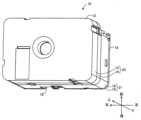
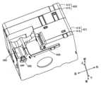
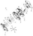
図1は、本発明の一実施形態であるカセット10を正面側すなわち上面から示す斜視図である。本実施形態の説明では、図1の上側をカセット10の前側とし、下側をカセット10の後側とし、右側をカセット10の左側とし、左側をカセット10の右側とし、左上側をカセット10の上側とし、右下側をカセット10の下側とする。図2は、カセット10を裏面側すなわち下面から示す斜視図である。図3は、カセット10の第1ケース部材12、第2ケース部材14、第3ケース部材16、および第4ケース部材18を分離させて、カセット10の内部構成を説明する斜視図である。カセット10は、全体として直方体状を成し、後述の図18に示す印刷装置102のカセット装着部104に着脱可能に装着される。カセット10は、第1ケース部材12および第2ケース部材14から構成される第1ケースすなわちテープケース20と、第3ケース部材16および第4ケース部材18から構成される第2ケースすなわちリボンケース21とを備えている。第1ケース部材12から第4ケース部材18は、図1に示す上下方向に積み重ねられている。第1ケース部材12、第2ケース部材14、第3ケース部材16および第4ケース部材18は、相互に重ねられた状態で、相互の外周壁間にそれぞれ設けられた複数の係止爪27と固定爪28との係合と位置決め突起29による位置決めとによって相互に固定されている。なお、本実施形態において、各ケース部材12~18の上側の面を上面もしくは正面と称し、下側の面を下面もしくは裏面と称す。
[Embodiment 1]
FIG. 1 is a perspective view showing acassette 10 that is an embodiment of the present invention from the front side, that is, from the top. In the description of this embodiment, the upper side of FIG. The upper side is the upper side, and the lower right side is the lower side of thecassette 10 . FIG. 2 is a perspective view showing thecassette 10 from the back side, that is, from the bottom side. FIG. 3 is a perspective view illustrating the internal configuration of thecassette 10 with thefirst case member 12, thesecond case member 14, thethird case member 16, and thefourth case member 18 of thecassette 10 separated. Thecassette 10 has a rectangular parallelepiped shape as a whole and is detachably attached to acassette attachment portion 104 of aprinting apparatus 102 shown in FIG. 18 which will be described later. Thecassette 10 comprises a first case ortape case 20 comprising afirst case member 12 and asecond case member 14, and a second case orribbon case 21 comprising athird case member 16 and afourth case member 18. and Thefirst case member 12 to thefourth case member 18 are stacked vertically as shown in FIG. Thefirst case member 12, thesecond case member 14, thethird case member 16, and thefourth case member 18 are stacked with a plurality of lockingclaws 27 provided between their outer peripheral walls. They are fixed to each other by engagement with fixedclaws 28 and positioning by positioningprojections 29 . In this embodiment, the upper surfaces of thecase members 12 to 18 are referred to as upper surfaces or front surfaces, and the lower surfaces are referred to as lower surfaces or rear surfaces.

リボンケース21は、テープケース20に対して上下方向の一方側に位置する。本実施形態では、リボンケース21は、テープケース20に対して上下方向の一方側である下側に位置する。テープケース20は、内部に形成された第1空間S1に被印刷媒体である印刷テープ22が巻回された印刷テープロール26を回転可能に収容する。印刷テープロール26は、帯状の印刷テープ22が円筒状の軸芯材である印刷テープスプール24に巻回されて構成される。印刷テープ22は、印刷テープ22の幅方向が第1方向である上下方向となるように巻回されている。印刷テープロール26の径方向は前後方向及び左右方向であり、径方向は上下方向に直交する直交方向である。直交方向は、上下方向に直交する平面に平行な任意の方向とも言い換えることができる。印刷テープ22、印刷テープスプール24、および印刷テープロール26は、被印刷媒体、印刷媒体スプール、および印刷媒体ロールに対応している。 Theribbon case 21 is positioned on one side of thetape case 20 in the vertical direction. In this embodiment, theribbon case 21 is located on the lower side, which is one side of thetape case 20 in the vertical direction. Thetape case 20 rotatably accommodates aprinting tape roll 26 around which aprinting tape 22, which is a medium to be printed, is wound in a first space S1 formed therein. Theprinting tape roll 26 is configured by winding the strip-shapedprinting tape 22 around aprinting tape spool 24 that is a cylindrical core member. Theprinting tape 22 is wound so that the width direction of theprinting tape 22 is the vertical direction, which is the first direction. The radial direction of theprinting tape roll 26 is the front-rear direction and the left-right direction, and the radial direction is the orthogonal direction perpendicular to the vertical direction. The orthogonal direction can also be rephrased as any direction parallel to a plane orthogonal to the vertical direction. Printingtape 22,printing tape spool 24, andprinting tape roll 26 correspond to the receiving medium, the printing medium spool, and the printing medium roll.

リボンケース21は、内部に形成された第2空間S2にインクリボンロール72及び貼合せテープロール64、巻取スプール76をそれぞれ回転可能に収容する。インクリボンロール72は、帯状のインクリボン68が、インクリボン68幅方向が上下方向となるように巻取スプール76に巻回されて構成される。インクリボン68は、帯状の印刷テープ22への印刷に使用される。巻取スプール76は、インクリボンロール72から引き出されたインクリボン68を巻き取る。貼合せテープロール64は、印刷された印刷テープ22に貼り合わされる帯状の貼合せテープ60が、貼合せテープ60の幅方向が上下方向となるように貼合せテープスプール62に巻回されている。 Theribbon case 21 rotatably accommodates theink ribbon roll 72, thebonding tape roll 64, and the take-upspool 76 in a second space S2 formed therein. Theink ribbon roll 72 is configured by winding a strip-shapedink ribbon 68 around a take-upspool 76 so that the width direction of theink ribbon 68 is the vertical direction. Theink ribbon 68 is used for printing on the strip-shapedprinting tape 22 . The take-upspool 76 takes up theink ribbon 68 pulled out from theink ribbon roll 72 . In thelamination tape roll 64, a band-shapedlamination tape 60 to be laminated to the printedprinting tape 22 is wound around thelamination tape spool 62 so that the width direction of thelamination tape 60 is the vertical direction. .

図2に示すように、カセット10の第4ケース部材18の下面には巻取スプール支持穴94が設けられている。巻取スプール支持穴94から、後述の巻取スプール76の連結穴96が露出している。連結穴96は、カセット10が印刷装置102のカセット装着部104に装着されたとき、カセット装着部104に設けられた巻取スプール駆動軸108が差し入れられる。また、第3ケース部材16および第4ケース部材18の側面すなわちリボンケース21の外周壁16wのうちの一部及び第2ケース部材14の外周壁の一部には、凹部99が形成されている。凹部99は、カセット10が印刷装置102のカセット装着部104に装着されたとき、カセット装着部104に設けられた後述の印刷ヘッド106が挿入される。図2に示すように、凹部99の上端は第2ケース部材14の下側の面で規定されている。 As shown in FIG. 2, a take-upspool support hole 94 is provided in the bottom surface of thefourth case member 18 of thecassette 10 . Aconnection hole 96 of the windingspool 76 , which will be described later, is exposed from the windingspool support hole 94 . A take-upspool drive shaft 108 provided in thecassette mounting portion 104 is inserted into the connectinghole 96 when thecassette 10 is mounted in thecassette mounting portion 104 of theprinting apparatus 102 . In addition,concave portions 99 are formed in the side surfaces of thethird case member 16 and thefourth case member 18, that is, a portion of the outerperipheral wall 16w of theribbon case 21 and a portion of the outer peripheral wall of thesecond case member 14. . When thecassette 10 is attached to thecassette mounting portion 104 of theprinting apparatus 102 , theconcave portion 99 receives aprint head 106 , which will be described later, provided on thecassette mounting portion 104 . As shown in FIG. 2 , the upper end of therecess 99 is defined by the lower surface of thesecond case member 14 .

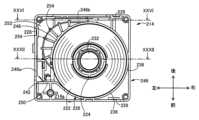
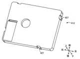
図4は、第1ケース部材12の上面側を示す正面図であり、図5は第1ケース部材12の下面側を示す斜視図である。図6は第2ケース部材14の上面側を印刷テープロールとともに示す正面図である。なお、図6では、印刷テープロール26から引き出された印刷テープ22の記載は省略されている。図7は第2ケース部材14の上面側を示す斜視図である。また、図8は印刷テープ22がテープケース20内からリボンケース21内へ架け渡されている状態を示す、図6のVIII-VIII視断面図である。図9は第2ケース部材14の下面側を示す斜視図であり、図10は第3ケース部材16の上面側を示す斜視図であり、図11は第3ケース部材16の下面側を示す斜視部である。図12は第4ケース部材18の上面側を示す斜視図であり、図13は第4ケース部材18の下面側を示す下面図である。 4 is a front view showing the upper surface side of thefirst case member 12, and FIG. 5 is a perspective view showing the lower surface side of thefirst case member 12. FIG. FIG. 6 is a front view showing the upper surface side of thesecond case member 14 together with the printing tape roll. 6, illustration of theprinting tape 22 pulled out from theprinting tape roll 26 is omitted. FIG. 7 is a perspective view showing the upper surface side of thesecond case member 14. FIG. 8 is a cross-sectional view taken along line VIII-VIII in FIG. 6, showing a state in which theprinting tape 22 is stretched from the inside of thetape case 20 to the inside of theribbon case 21. As shown in FIG. 9 is a perspective view showing the bottom side of thesecond case member 14, FIG. 10 is a perspective view showing the top side of thethird case member 16, and FIG. 11 is a perspective view showing the bottom side of thethird case member 16. FIG. Department. 12 is a perspective view showing the top side of thefourth case member 18, and FIG. 13 is a bottom view showing the bottom side of thefourth case member 18. As shown in FIGS.

第1ケース部材12と第2ケース部材14との間の第1空間S1には、印刷テープロール26が上下方向に平行な第1回転中心線C1まわりに回転可能に収容されている。なお、第1回転中心線C1は、印刷テープロール26の回転中心であるとともに、印刷テープスプール24の回転中心でもある。第1ケース部材12および第2ケース部材14は長方形状であって、第1回転中心線C1は、第1ケース部材12および第2ケース部材14における、第2方向である左右方向の中央略右寄り、且つ、第3方向である前後方向の略中央付近に位置している。印刷テープ22は、たとえば図15に示すように、剥離テープ22cが被印刷テープ22aの印刷面とは反対側の面に、粘着剤22bを介して積層されることにより構成されたものである。 Aprinting tape roll 26 is accommodated in a first space S1 between thefirst case member 12 and thesecond case member 14 so as to be rotatable about a first rotation center line C1 parallel to the vertical direction. The first rotation center line C<b>1 is the rotation center of theprinting tape roll 26 and also the rotation center of theprinting tape spool 24 . Thefirst case member 12 and thesecond case member 14 are rectangular, and the first rotation center line C1 is substantially to the right of the center of thefirst case member 12 and thesecond case member 14 in the left-right direction, which is the second direction. , and located near the approximate center in the front-rear direction, which is the third direction. As shown in FIG. 15, for example, theprinting tape 22 is constructed by laminating a peelingtape 22c on the opposite side of the printing surface of theprinting tape 22a with an adhesive 22b interposed therebetween.

図3、図5に示すように、第1ケース部材12の下面側には、円筒状の第1支持突起30と、第1円周壁34とが設けられる。第1支持突起30は、円筒状の印刷テープスプール24に挿入され印刷テープロール26を回転可能に支持する。第1円周壁34は、印刷テープロール26の外径よりも大きい内径を有する。第1支持突起30と第1円周壁34は、第1回転中心線C1と同じ中心線を有する状態で第1ケース部材12の下面側から下向きに突設されている。図6及び図7に示すように、第2ケース部材14の上面側には、円筒状の第2支持突起32と、第2円周壁36とが設けられる。第2支持突起32は、円筒状の印刷テープスプール24に挿入され印刷テープロール26を回転可能に支持する。第2円周壁36は、印刷テープロール26の外径よりも大きい内径を有する。第2支持突起32と第2円周壁36は、第1回転中心線C1と同じ中心線を有する状態で第2ケース部材14の上面側から上向きに突設されている。印刷テープロール26は、印刷テープロール26の外径と略同じ外径を有する円形のスペーサフィルム38を印刷テープロール26の上下にそれぞれ介在させた状態で第1ケース部材12と第2ケース部材14との間に配設されている。スペーサフィルム38は、印刷テープロール26を円滑に回転させるためのものであり、たとえば4フッ化エチレン樹脂シートから構成されたものである。 As shown in FIGS. 3 and 5 , a cylindricalfirst support projection 30 and a firstcircumferential wall 34 are provided on the lower surface side of thefirst case member 12 . Thefirst support protrusion 30 is inserted into the cylindricalprinting tape spool 24 and rotatably supports theprinting tape roll 26 . The firstcircumferential wall 34 has an inner diameter that is greater than the outer diameter of theprinting tape roll 26 . Thefirst support projection 30 and the firstcircumferential wall 34 protrude downward from the lower surface side of thefirst case member 12 while having the same center line as the first rotation center line C1. As shown in FIGS. 6 and 7 , a cylindricalsecond support projection 32 and a secondcircumferential wall 36 are provided on the upper surface side of thesecond case member 14 . Thesecond support protrusions 32 are inserted into the cylindricalprinting tape spool 24 and rotatably support theprinting tape roll 26 . The secondcircumferential wall 36 has an inner diameter that is greater than the outer diameter of theprinting tape roll 26 . Thesecond support projection 32 and the secondcircumferential wall 36 protrude upward from the upper surface side of thesecond case member 14 while having the same center line as the first rotation center line C1. Theprinting tape roll 26 is arranged between thefirst case member 12 and thesecond case member 14 withcircular spacer films 38 having substantially the same outer diameter as theprinting tape roll 26 interposed above and below theprinting tape roll 26, respectively. is placed between. Thespacer film 38 is for smoothly rotating theprinting tape roll 26, and is made of, for example, a tetrafluoroethylene resin sheet.

第1ケース部材12の下面側および第2部材14ケースの上面側には、図5および図6に示すように、印刷テープロール26から印刷テープ22を一定の位置から引き出すために第1円周壁34および第2円周壁36の一部を切り欠いて形成した印刷テープゲート40、42が形成されている図7に示すように、第2ケース部材14の上面側には、印刷テープロール26から引き出された印刷テープ22を一定の方向に案内するために、印刷テープゲート42の左端から左側へ延びる案内壁50が形成されている。 5 and 6, on the bottom side of thefirst case member 12 and on the top side of the case of thesecond member 14, a first circumferential wall for drawing theprinting tape 22 from the printing tape roll 26 from a fixed position. 34 andprinting tape gates 40 and 42 formed by cutting out a part of the secondcircumferential wall 36. As shown in FIG. Aguide wall 50 extending leftward from the left end of theprinting tape gate 42 is formed to guide the pulled out printingtape 22 in a fixed direction.

図6に示すように、印刷テープゲート42の左端から左方向へ延びる案内壁50は、外周壁46の短辺部46aに到達する前に長辺部46b側すなわち後方へ曲がり、第2円周壁36に沿って延設されて長辺部44bへ接続されている。 As shown in FIG. 6, theguide wall 50 extending leftward from the left end of theprinting tape gate 42 bends toward thelong side 46b, i.e., rearward, before reaching theshort side 46a of the outerperipheral wall 46, and bends toward the second peripheral wall. 36 and connected to thelong side 44b.

図6に示すように、第2ケース部材14の底板14aには、案内壁50と外周壁46の長辺部46bとに沿って前後方向及び左右方向に延びる正面視略L字状の貫通穴52が形成されている。底板14aには、第2円周壁36のうち案内壁50および長辺部46bに対向する部分と貫通穴52との間において複数の案内リブ54が形成されている。複数の案内リブ54は、印刷テープロール26から巻き出され且つ印刷テープゲート40および42を通して送り出された印刷テープ22を貫通穴52内へ案内する。 As shown in FIG. 6, in thebottom plate 14a of thesecond case member 14, a substantially L-shaped through hole extending in the front-rear direction and the left-right direction along theguide wall 50 and thelong side portion 46b of the outerperipheral wall 46 is formed. 52 are formed. A plurality ofguide ribs 54 are formed on thebottom plate 14 a between the throughhole 52 and the portion of the secondcircumferential wall 36 facing theguide wall 50 and thelong side portion 46 b. A plurality ofguide ribs 54 guide theprinting tape 22 unwound from theprinting tape roll 26 and fed through theprinting tape gates 40 and 42 into the through holes 52 .

図7は、第1ケース部材12を取り除いたカセット10を示す。図7に示すように、印刷テープロール26から巻き出された印刷テープ22が、貫通穴52を通して第3ケース部材16と第4ケース部材18との間の第2空間内S2へ導かれている。印刷テープ22は、第1空間S1と第2空間内S2との間を区画する底板14aに形成された貫通穴52を通して、テープケース20とリボンケース21とに架け渡される。FIG. 7 shows thecassette 10 with thefirst case member 12 removed. As shown in FIG. 7, theprinting tape 22 unwound from theprinting tape roll 26 is guided into the second space S2 between thethird case member 16 and thefourth case member 18 through the throughhole 52. . Theprinting tape 22 spans thetape case 20 and theribbon case 21 through a throughhole 52 formed in thebottom plate 14a that separates the first space S1 and the second space S2.

図8に示すように、印刷テープ22が、貫通穴52を通して、テープケース20内からリボンケース21内へ斜めに架け渡される。より詳細には、後述する図14に示すように、印刷テープ22は、リボンケース21の凹部99にまで架け渡されている。図9は、第2ケース部材14の下面側を示している。図9に示すように、第2ケース部材14の底板14aの裏面には、貫通穴52が開口しており、貫通穴52に沿って案内壁56が上下方向に立設されている。図10は、第3ケース部材16の上面側を示している。第3ケース部材16の天井板16eには、貫通穴58と、貼合せテープロール支持穴66と、インクリボン支持穴74と、巻取スプール支持穴78と、ローラ支持穴82とが、形成されている。貫通穴58は、印刷テープロール26から引き出された印刷テープ22を第2空間S2へ通すために、第2ケース部材14の貫通穴52に対応する位置に形成されている。つまり、貫通穴52の一部と貫通穴58の一部は上下方向において互いに重複している。 As shown in FIG. 8, theprinting tape 22 is diagonally stretched from the inside of thetape case 20 to the inside of theribbon case 21 through the through holes 52 . More specifically, as shown in FIG. 14 to be described later, theprint tape 22 is stretched over therecess 99 of theribbon case 21 . 9 shows the bottom side of thesecond case member 14. FIG. As shown in FIG. 9 , a throughhole 52 is opened in the rear surface of thebottom plate 14 a of thesecond case member 14 , and aguide wall 56 is provided vertically along the throughhole 52 . 10 shows the top side of thethird case member 16. FIG. Theceiling plate 16e of thethird case member 16 is formed with a throughhole 58, a bonding taperoll support hole 66, an inkribbon support hole 74, a take-upspool support hole 78, and aroller support hole 82. ing. A throughhole 58 is formed at a position corresponding to the throughhole 52 of thesecond case member 14 so that theprinting tape 22 pulled out from theprinting tape roll 26 is passed through the second space S2. That is, a portion of the throughhole 52 and a portion of the throughhole 58 overlap each other in the vertical direction.

第2ケース部材14の底板14aおよび第3ケース部材16の天井板16eは、テープケース20内の第1空間S1とリボンケース21内の第2空間S2とを区画する。 Thebottom plate 14a of thesecond case member 14 and theceiling plate 16e of thethird case member 16 partition the first space S1 inside thetape case 20 and the second space S2 inside theribbon case 21 .

貼合せテープロール支持穴66は、貼合せテープ60が巻回された貼合せテープスプール62の一端を嵌め入れて貼合せテープロール64を第1回転中心線C1と平行な第2回転中心線C2まわりに回転可能に支持する。なお、第2回転中心線C2は、貼合せテープロール64の回転中心であるとともに、貼合せテープスプール62の回転中心でもある。貼合せテープ60は、図15に示すように、印刷テープ22の印刷面を保護するためにたとえばこの印刷面と接触する一面に粘着剤60bが塗布された透明フィルム60aから成る。インクリボン支持穴74は、インクリボン68が巻回された供給スプール70の一端を嵌め入れてインクリボンロール72を第1回転中心線C1と平行な第3回転中心線C3まわりに回転可能に支持する。なお、第3回転中心線C3は、インクリボンロール72の回転中心であるとともに、供給プール70の回転中心でもある。巻取スプール支持穴78は、インクリボンロール72から巻き出されたインクリボン68を巻き取る巻取スプール76の一端を嵌め入れて巻取スプール76を第1回転中心線C1と平行な第4回転中心線C4まわりに回転可能に支持する。なお、第4回転中心線C4は、巻取スプール24の回転中心である。ローラ支持穴82は、印刷テープ22の印刷面と貼合せテープ60の接着面とを圧着するために印刷テープ22と貼合せテープ60とを印刷装置102のローラとの間で挟圧するローラ80の一端を嵌め入れてローラ80を第1回転中心線C1と平行な第5回転中心線C5まわりに回転可能に支持する。 One end of thelamination tape spool 62 around which thelamination tape 60 is wound is inserted into the lamination taperoll support hole 66 so that thelamination tape roll 64 is positioned on the second rotation center line C2 parallel to the first rotation center line C1. Support rotatable around. The second rotation center line C2 is the center of rotation of thebonding tape roll 64 and the center of rotation of thebonding tape spool 62 as well. As shown in FIG. 15, the laminatingtape 60 is composed of atransparent film 60a coated with an adhesive 60b on one surface that contacts the printing surface of theprinting tape 22, for example, in order to protect the printing surface. One end of thesupply spool 70 around which theink ribbon 68 is wound is inserted into the inkribbon support hole 74 to support theink ribbon roll 72 rotatably around a third rotation center line C3 parallel to the first rotation center line C1. do. The third rotation center line C3 is the center of rotation of theink ribbon roll 72 and the center of rotation of thesupply pool 70 as well. One end of a windingspool 76 for winding theink ribbon 68 unwound from theink ribbon roll 72 is fitted into the windingspool support hole 78, and the windingspool 76 is rotated in a fourth rotation parallel to the first rotation center line C1. It is rotatably supported around the center line C4. The fourth rotation center line C4 is the rotation center of the take-upspool 24. As shown in FIG. The roller support holes 82 are formed by therollers 80 that pinch theprinting tape 22 and thebonding tape 60 between the printingtape 22 and thebonding tape 60 and the rollers of theprinting device 102 in order to press the printing surface of theprinting tape 22 and the adhesive surface of thebonding tape 60 together. One end is fitted to support theroller 80 so as to be rotatable about a fifth rotation center line C5 parallel to the first rotation center line C1.

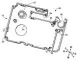
図11に示すように、第3ケース部材16の下面には、貼合せテープロール保持壁84と、インクリボンロール保持壁86と、円筒状突起88と、円弧状壁92とが、形成されている。貼合せテープロール保持壁84および円弧状壁92は、貼合せテープロール64
の配置位置を規定するために貼合せテープロール支持穴66の周囲に貼合せテープロール支持穴66を中心とする円弧状に形成されている。インクリボンロール保持壁86は、巻取スプール76に巻き取られたインクリボン68のインクリボンロール配置位置を規定するために巻取スプール支持穴78の周囲に巻取スプール支持穴78を中心とする円弧状に形成されている。円筒状突起88は、インクリボン支持穴74の周囲から下方に突設され且つ先端面に周方向に並ぶ凹凸が形成されている。また、第3ケース部材16の下面には、貼合せテープ60の貼り付きを防止する貼付防止ローラ91の上端部を回動可能に支持する支持突起93が設けられている。また、図12に示すように、第4ケース部材18の上面には、貼付防止ローラ91の下端部を連結可能に支持する支持突起95が設けられている。
As shown in FIG. 11, the lower surface of thethird case member 16 is formed with a lamination taperoll holding wall 84, an ink ribbonroll holding wall 86, acylindrical protrusion 88, and anarcuate wall 92. there is Laminating taperoll retaining wall 84 andarcuate wall 92 hold thelaminating tape roll 64
is formed in an arc around the lamination taperoll support hole 66 to define the arrangement position of the lamination taperoll support hole 66 . The ink ribbonroll retaining wall 86 is centered around the take-upspool support hole 78 to define the ink ribbon roll placement position of theink ribbon 68 wound on the take-upspool 76 . It is formed in an arc shape. Thecylindrical projection 88 projects downward from the periphery of the inkribbon support hole 74 and has unevenness arranged in the circumferential direction on the tip surface thereof. Further, on the lower surface of thethird case member 16, asupport protrusion 93 is provided to rotatably support the upper end of a stickingprevention roller 91 that prevents sticking of the stickingtape 60. As shown in FIG. Further, as shown in FIG. 12, the upper surface of thefourth case member 18 is provided with asupport protrusion 95 that supports the lower end of the stickingprevention roller 91 so as to be connectable.

図3に示されるように、インクリボン68が巻回された供給スプール70の他端には、クラッチばねを収容したクラッチばねホルダ90が嵌め付けられており、供給スプール70がクラッチばねホルダ90内のクラッチばねによってインクリボンロール72には適度の回転抵抗が付与されるようになっている。 As shown in FIG. 3, aclutch spring holder 90 containing a clutch spring is fitted to the other end of thesupply spool 70 around which theink ribbon 68 is wound. A suitable rotational resistance is imparted to theink ribbon roll 72 by the clutch spring of .

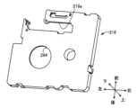
図12および図13は、第4ケース部材18の上面および下面を示している。第4ケース部材18側において巻取スプール76の他端を嵌め入れて巻取スプール76を回転可能に支持する巻取スプール支持穴94が貫通して形成されている。第4ケース部材18には、供給スプール70の他端を嵌め入れて供給スプール70を回転可能に支持する円筒状の支持突起97が形成されている。巻取スプール76の他端側の端面に形成された連結穴96が、図2に示すように巻取スプール支持穴94を通して第4ケース部材18の下面に露出させられる。カセット10が印刷装置102に装着されたとき、後述の印刷装置102の巻取スプール駆動軸108が連結穴96内に挿入されて巻取スプール76に連結され、巻取スプール76が上記駆動軸により回転駆動される。 12 and 13 show the upper and lower surfaces of thefourth case member 18. FIG. A windingspool support hole 94 is formed through thefourth case member 18 side to fit the other end of the windingspool 76 and rotatably support the windingspool 76 . Acylindrical support projection 97 is formed on thefourth case member 18 to fit the other end of thesupply spool 70 and rotatably support thesupply spool 70 . A connectinghole 96 formed in the end surface of the other end of the take-upspool 76 is exposed to the lower surface of thefourth case member 18 through the take-upspool support hole 94 as shown in FIG. When thecassette 10 is attached to theprinting device 102, the take-upspool drive shaft 108 of theprinting device 102, which will be described later, is inserted into the connectinghole 96 and connected to the take-upspool 76, and the take-upspool 76 is driven by the drive shaft. rotationally driven.

第4ケース部材18には、第3ケース部材16に形成されたローラ支持穴82に対応する位置に、ローラ80の軸端を露出させるローラ露出穴98が設けられている。ローラ80の第4ケース部材18側の端部に形成された連結部80aが、図2に示すようにローラ露出穴98を通して第4ケース部材18の下面に露出させられる。カセット10が印刷装置102に装着されたとき、後述の印刷装置102のローラ駆動軸110が連結部80aと連結され、ローラ80がローラ駆動軸110により回転駆動される。 Thefourth case member 18 is provided with aroller exposure hole 98 for exposing the shaft end of theroller 80 at a position corresponding to theroller support hole 82 formed in thethird case member 16 . A connectingportion 80a formed at the end portion of theroller 80 on the side of thefourth case member 18 is exposed to the lower surface of thefourth case member 18 through theroller exposing hole 98 as shown in FIG. When thecassette 10 is attached to theprinting device 102 , theroller driving shaft 110 of theprinting device 102 , which will be described later, is connected to the connectingportion 80 a , and theroller 80 is rotationally driven by theroller driving shaft 110 .

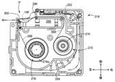
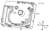
図2、図11に示すように、第3ケース部材16および第4ケース部材18から構成されるリボンケース21には、カセット10が図18に示すカセット装着部104に装着されたとき、カセット装着部104に立設された印刷ヘッド106を保持するヘッド保持板114を収容するための凹部99が形成されている。図11に示すように、第3ケース部材16の外周壁16wの一部には、積重ね方向に対応する上下方向と直交する第2方向である前後方向に伸びる第1側壁16aと、第1側壁16aの前端部から上下方向および前後方向と直交する第3方向である左右方向に伸びる第2側壁16bと、凹部99を囲むU字状の凹部壁16cとが、形成されている。凹部壁16cは、第2側壁16bと前後方向に対向し左右方向に延びる内壁16hと、内壁16hの右端から後方に延びる内壁16iと、内壁16iの後端から左方に延びる内壁16jと、内壁16jの左端から前方に延びる内壁16kとから構成される。第2側壁16b及び凹部壁16cによって、凹部99は、第2側壁16bの左側端部から後方に延び、且つ、第2側壁16bよりも後方において左右方向に延びるように規定されている。第4ケース部材18には、図12および図13に示すように、凹部壁16cに対応するU字状の切欠き18aが形成されている。これら凹部壁16cおよび切欠き18aによって、凹部99が形成されている。図2に示すように、凹部99の上端の一部は、第2ケース部材14の下面によって規定されている。すなわち、凹部99は、第2ケース部材14及び第1ケース部材12と上下方向において重なっている。 As shown in FIGS. 2 and 11, theribbon case 21, which is composed of thethird case member 16 and thefourth case member 18, has a cassette mounting portion when thecassette 10 is mounted in thecassette mounting portion 104 shown in FIG. Arecess 99 is formed to accommodate ahead holding plate 114 that holds theprint head 106 erected on theportion 104 . As shown in FIG. 11, a part of the outerperipheral wall 16w of thethird case member 16 includes afirst side wall 16a extending in the front-rear direction, which is a second direction perpendicular to the vertical direction corresponding to the stacking direction, and afirst side wall 16a. Asecond side wall 16b extending in the horizontal direction, which is a third direction perpendicular to the vertical direction and the front-rear direction, from the front end portion of 16a, and a U-shaped recessedportion wall 16c surrounding the recessedportion 99 are formed. The recessedwall 16c includes aninner wall 16h extending in the left-right direction facing thesecond side wall 16b in the front-rear direction, aninner wall 16i extending rearward from the right end of theinner wall 16h, and aninner wall 16j extending leftward from the rear end of the inner wall 16i. and aninner wall 16k extending forward from the left end of 16j. Therecess 99 is defined by thesecond side wall 16b and therecess wall 16c so as to extend rearward from the left end of thesecond side wall 16b and extend in the left-right direction behind thesecond side wall 16b. As shown in FIGS. 12 and 13, thefourth case member 18 is formed with aU-shaped notch 18a corresponding to therecess wall 16c. Arecess 99 is formed by therecess wall 16c and thenotch 18a. As shown in FIG. 2 , part of the upper end of therecess 99 is defined by the lower surface of thesecond case member 14 . That is, theconcave portion 99 vertically overlaps thesecond case member 14 and thefirst case member 12 .

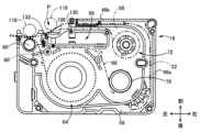
図14は、カセット10が印刷装置102のカセット装着部104に装着されたときの、第3ケース部材16の下面を示す図である。前述の通り、印刷テープ22は、印刷テープロール26から引き出され、貫通穴52および貫通穴58を介してテープケース20内の第1空間S1からリボンケース21内の第2空間S2に斜めに架け渡される。そのため、第3ケース部材16を示す図14において印刷テープ22は、第3ケース部材16の後方の貫通穴58から描画されている。図14に示すように、印刷テープ22および貼合せテープ60は、ローラ80と印刷装置102の押圧ローラ118とに挟圧され、ローラ80の駆動によって、各々印刷テープロール26貼合せテープロール64から引き出される。インクリボン68は、巻取スプール76の駆動によってインクリボンロール72から引き出され、巻取スプール76に巻き取られる。図14は、印刷テープ22、インクリボン68および貼合せテープ60の搬送経路を示している。印刷テープ22は二点鎖線で、貼合せテープ60は破線で、インクリボン68は一点鎖線で示されている。 FIG. 14 is a diagram showing the bottom surface of thethird case member 16 when thecassette 10 is attached to thecassette attachment portion 104 of theprinting apparatus 102. FIG. As described above, theprinting tape 22 is pulled out from theprinting tape roll 26 and diagonally stretched from the first space S1 in thetape case 20 to the second space S2 in theribbon case 21 through the throughholes 52 and 58. Passed. Therefore, in FIG. 14 showing thethird case member 16 , theprinting tape 22 is drawn from the throughhole 58 behind thethird case member 16 . As shown in FIG. 14, theprinting tape 22 and thelaminating tape 60 are pressed between theroller 80 and thepressing roller 118 of theprinting device 102, and theroller 80 is driven to drive theprinting tape roll 26 and thelaminating tape roll 64 from theprinting tape roll 26 and thelaminating tape roll 64, respectively. pulled out. Theink ribbon 68 is pulled out from theink ribbon roll 72 by driving the windingspool 76 and wound on the windingspool 76 . FIG. 14 shows the conveying paths of theprinting tape 22, theink ribbon 68 and thebonding tape 60. As shown in FIG. Theprinting tape 22 is shown in dashed lines, thelamination tape 60 is shown in dashed lines, and theink ribbon 68 is shown in dashed lines.

図14に示すように、巻取スプール76およびローラ80が回転駆動されると、排出口130から印刷テープ22およびインクリボン68が重ねられた状態で印刷場所Pへ向かって排出される。排出口130は、第2側壁16bの左端部と側壁16hの左端部により規定され、左右方向に貫通する間隙である。印刷ヘッド106とプラテンローラ116との間の印刷場所Pにおいて、印刷テープ22はインクリボン68を介して印刷ヘッド106に押しつけられる。この状態で、印刷ヘッド106の表面に配置された複数の発熱素子が選択的に駆動されて局所発熱することで、インクリボン68の一面に設けられたインク68aのうち一部が印刷テープ22に転写されて、印刷テープ22に文字、記号などが印刷される。印刷場所Pを通過した使用済のインクリボン68は、搬入口132からリボンケース21内に搬入され、巻取スプール76に巻き取られる。搬入口132は、排出口130よりも左側に位置し、第3ケース部材16に設けられている。印刷場所Pを通過した印刷テープ22の印刷面には、ローラ80により透明な貼合せテープ60が押しつけられて接着される。これにより、印刷テープ22の印刷面は貼合せテープ60により保護される。 As shown in FIG. 14, when the take-upspool 76 androller 80 are driven to rotate, theprinting tape 22 and theink ribbon 68 are discharged toward the printing place P from thedischarge port 130 in a state of being superimposed. Thedischarge port 130 is defined by the left end of thesecond side wall 16b and the left end of theside wall 16h, and is a gap penetrating in the left-right direction. At a print station P between theprint head 106 and theplaten roller 116 , theprint tape 22 is pressed against theprint head 106 via theink ribbon 68 . In this state, a plurality of heating elements arranged on the surface of theprint head 106 are selectively driven to locally generate heat, so that part of theink 68 a provided on one surface of theink ribbon 68 is transferred to theprinting tape 22 . Characters, symbols, etc. are printed on theprinting tape 22 by being transferred. The usedink ribbon 68 that has passed through the printing place P is carried into theribbon case 21 through the carry-inport 132 and taken up by the take-upspool 76 . The carry-inport 132 is located on the left side of thedischarge port 130 and is provided in thethird case member 16 . Atransparent laminating tape 60 is pressed by aroller 80 and adhered to the printing surface of theprinting tape 22 that has passed through the printing place P. As shown in FIG. Thereby, the printing surface of theprinting tape 22 is protected by thebonding tape 60 .

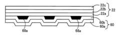
図15は、カセット10から送り出された印刷テープ22および貼合せテープ60の積層体を模式的に示している。印刷テープ22の被印刷テープ22a側すなわち印刷面側に、一面に粘着剤60bが塗布された透明フィルム60aから構成された貼合せテープ60が、貼り着けられている。これにより、印刷テープ22の印刷面に転写されたインク68aが保護される。なお、図15に描かれた積層体の各部材22a~22c,60a,60b,68aの大きさや寸法比等は必ずしも正確ではない。 FIG. 15 schematically shows a laminate of theprinting tape 22 and thebonding tape 60 fed from thecassette 10. As shown in FIG. Alamination tape 60 composed of atransparent film 60a coated with an adhesive 60b on one side is adhered to theprint tape 22a side of theprinting tape 22, that is, the printing surface side. As a result, theink 68a transferred to the printing surface of theprinting tape 22 is protected. Note that the sizes and dimensional ratios of themembers 22a to 22c, 60a, 60b, and 68a of the laminate shown in FIG. 15 are not necessarily accurate.

図16は、第3ケース部材16の下面を示す図である。第3ケース部材16と第4ケース部材18との間の第2空間S2内すなわちリボンケース21内には、貼合せテープロール64、インクリボンロール72、巻取スプール76、およびローラ80が収容される。上述したように、リボンケース21は、テープケース20に対して下方に重ねて配置されている。テープケース20内に収容された印刷テープロール26およびスペーサフィルム38を、第2空間S2内で前後方向および左右方向に広がる投影面上に対し上下方向に投影した場合、印刷テープロール26およびスペーサフィルム38の投影位置は図16の一点鎖線で示される。なお、スペーサフィルム38は印刷テープロール26と略同じ直径を有するので、図16では印刷テープロール26を表す一点鎖線のみを記載する。図16に示すように、貼合せテープロール64、インクリボンロール72及び巻取スプール76は、印刷テープロール26と上下方向に重なる位置に配置されている。貼合せテープロール64の少なくとも一部及び貼合せテープスプール62の少なくとも一部は、印刷テープロール26と上下方向に重なっている。より詳細には、貼合せテープロール64の一部及び貼合せテープスプール62の一部は、それぞれ印刷テープスプール24及び印刷テープスプール24に巻回された印刷テープ22と上下方向に重なっている。 16 is a diagram showing the bottom surface of thethird case member 16. FIG. Abonding tape roll 64, anink ribbon roll 72, a take-upspool 76, and aroller 80 are accommodated in the second space S2 between thethird case member 16 and thefourth case member 18, that is, theribbon case 21. be. As described above, theribbon case 21 is arranged to overlap thetape case 20 downward. When theprinting tape roll 26 and thespacer film 38 accommodated in thetape case 20 are vertically projected onto the projection plane extending in the front-rear direction and the left-right direction in the second space S2, theprinting tape roll 26 and the spacer film The projection position of 38 is indicated by the dashed line in FIG. Since thespacer film 38 has approximately the same diameter as theprinting tape roll 26, FIG. 16 shows only the dashed line representing theprinting tape roll 26. As shown in FIG. 16, thebonding tape roll 64, theink ribbon roll 72, and the take-upspool 76 are arranged at positions overlapping theprinting tape roll 26 in the vertical direction. At least a portion of thelamination tape roll 64 and at least a portion of thelamination tape spool 62 vertically overlap theprinting tape roll 26 . More specifically, a portion of thelamination tape roll 64 and a portion of thelamination tape spool 62 vertically overlap theprinting tape spool 24 and theprinting tape 22 wound on theprinting tape spool 24, respectively.

図16において、印刷テープロール26およびそれと略同径のスペーサフィルム38は、貼合せテープスプール62を有する貼合せテープロール64の少なくとも一部およびその第2回転中心線C2、インクリボンロール72の少なくとも一部およびその第3回転中心線C3、巻取スプール76の少なくとも一部およびその第4回転中心線C4、凹部99および凹部壁16cの少なくとも一部と上下方向において重なっている。印刷テープロール26およびスペーサフィルム38を上下方向に投影した場合、その投影面の中に、貼合せテープロール64およびその第2回転中心線C2、インクリボンロール72およびその第3回転中心線C3、および巻取スプール76およびその第4回転中心線C4、凹部99および凹部壁16cが位置している。また、凹部99および凹部壁16cの少なくとも一部は、印刷テープスプール24と上下方向において重なっている。また、左右方向において、印刷テープロール26の一部および印刷テープスプール24の回転中心である第1回転中心線C1は、凹部99の左右方向の一方側端部である右側端部99aと他方側端部である左側端部99bとの間に位置している。また、印刷テープスプール24の回転中心である第1回転中心線C1は、左右方向において排出口130と凹部99の右側端部99aとの間に位置している。また、貼合せテープスプール62は、左右方向において凹部99の右側端部99aと左側端部99bとの間に位置している。特に貼合せテープスプール62の回転中心でもある第2回転中心線C2は、左右方向において凹部99の右側端部99aと排出口130との間に位置している。さらに、図16において、前後方向および左右方向において、カセット10の前後方向の中心且つ左右方向の中心である中心位置Mから印刷テープロール26の第1回転中心線C1までの距離は、中心位置Mから凹部99までの距離よりも小さく設定されている。 In FIG. 16, theprinting tape roll 26 and thespacer film 38 of approximately the same diameter are formed by at least a portion of thelamination tape roll 64 having thelamination tape spool 62 and its second rotational centerline C2, and at least theink ribbon roll 72. It vertically overlaps a part and its third rotation center line C3, at least a part of the take-upspool 76 and its fourth rotation center line C4, therecess 99 and at least a part of therecess wall 16c. When theprinting tape roll 26 and thespacer film 38 are projected in the vertical direction, thelamination tape roll 64 and its second rotation center line C2, theink ribbon roll 72 and its third rotation center line C3, and take-upspool 76 and its fourth centerline of rotation C4,recess 99 andrecess wall 16c are located. At least a portion of therecess 99 and therecess wall 16c overlaps theprinting tape spool 24 in the vertical direction. In the left-right direction, the first rotation center line C1, which is the center of rotation of a portion of theprinting tape roll 26 and theprinting tape spool 24, is aligned with theright end 99a, which is one end of therecess 99 in the left-right direction, and the other side. It is positioned between theleft end portion 99b, which is the end portion. Also, the first rotation center line C1, which is the rotation center of theprinting tape spool 24, is positioned between thedischarge port 130 and theright end 99a of therecess 99 in the left-right direction. Thebonding tape spool 62 is positioned between theright end 99a and theleft end 99b of therecess 99 in the left-right direction. In particular, the second rotation center line C2, which is also the rotation center of thebonding tape spool 62, is positioned between theright end 99a of therecess 99 and thedischarge port 130 in the left-right direction. Further, in FIG. 16, in the front-back direction and the left-right direction, the distance from the center position M, which is the center of thecassette 10 in the front-back direction and the center in the left-right direction, to the first rotation center line C1 of theprinting tape roll 26 is the center position M to theconcave portion 99.

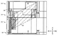
図17は、図6のXVII-XVII視断面図である。上下方向において、印刷テープロール26の上下方向の一方側(下側)端部と、貼合せテープロール64の上下方向の他方側(上側)端部との間の距離Dは、貼合せテープ60の幅寸法W1よりも小さい。印刷テープ22と貼合せテープ60とは同じ幅寸法であるので、距離Dは、印刷テープロール26の幅寸法よりも小さい。 17 is a sectional view taken along line XVII-XVII of FIG. 6. FIG. In the vertical direction, the distance D between the one (lower) end of theprinting tape roll 26 in the vertical direction and the other (upper) end of thelamination tape roll 64 is the length of thelamination tape 60 . is smaller than the width dimension W1 of the Since theprinting tape 22 and thelamination tape 60 have the same width dimension, the distance D is smaller than the width dimension of theprinting tape roll 26 .

図18は、印刷システム122に含まれる印刷装置102の一部に設けられたカセット装着部104を示している。カセット装着部104には、嵌め入れられたカセット10を位置決めする矩形の位置決め穴112と、位置決め穴112の下面に立設された巻取スプール駆動軸108およびローラ駆動軸110とが設けられている。位置決め穴112は、カセット10の下ケースであるリボンケース21の一部を収容する収容部として機能している。これら巻取スプール駆動軸108およびローラ駆動軸110は、図示しないステップモータによりギヤ機構を介して同じ方向に回転駆動される。また、カセット装着部104の位置決め穴112の下面には、熱式の印刷ヘッド(サーマルプリントヘッド)106が固着されたヘッド保持板114が立設されており、プラテンローラ116および押圧ローラ118が回転可能に先端部に設けられたプラテン保持部材120がその基端部まわりに回動可能に設けられている。ヘッド保持板114は、たとえばアルミニウム製の金属板であって、印刷ヘッドのヒートシンクを兼ねている。 FIG. 18 shows thecassette mounting section 104 provided in a part of theprinting device 102 included in theprinting system 122. As shown in FIG. Thecassette mounting portion 104 is provided with arectangular positioning hole 112 for positioning the insertedcassette 10, and a take-upspool drive shaft 108 and aroller drive shaft 110 erected on the lower surface of thepositioning hole 112. . Thepositioning hole 112 functions as an accommodation portion that accommodates a portion of theribbon case 21 that is the lower case of thecassette 10 . The take-upspool drive shaft 108 androller drive shaft 110 are rotated in the same direction by a step motor (not shown) via a gear mechanism. Ahead holding plate 114 to which athermal print head 106 is fixed is erected on the lower surface of thepositioning hole 112 of thecassette mounting portion 104. Aplaten roller 116 and apressure roller 118 rotate. Aplaten holding member 120 is provided at its distal end and is rotatable about its proximal end. Thehead holding plate 114 is a metal plate made of aluminum, for example, and also serves as a heat sink for the print head.

カセット10が、印刷装置102のカセット装着部104に装着されると、カセット装着部104に立設された巻取スプール駆動軸108およびローラ駆動軸110が巻取スプール76およびローラ80に連結される。次いで、カセット10がカセット装着部104に装着された状態で印刷装置102の図示しないカバーが閉じられると、プラテン保持部材120がその基端部まわりに回動させられて、プラテンローラ116および押圧ローラ118が印刷ヘッド106およびカセット10のローラ80へ押圧されるようになっている。印刷装置102とカセット10とが、印刷システム122を構成している。 When thecassette 10 is attached to thecassette attachment portion 104 of theprinting apparatus 102 , the take-upspool drive shaft 108 and theroller drive shaft 110 erected on thecassette attachment portion 104 are connected to the take-upspool 76 and theroller 80 . . Next, when the cover (not shown) of theprinting apparatus 102 is closed with thecassette 10 attached to thecassette attachment portion 104, theplaten holding member 120 is rotated around its base end portion, and theplaten roller 116 and the pressure roller are rotated. 118 are adapted to be pressed against theprint head 106 and therollers 80 of thecassette 10 . Theprinting device 102 and thecassette 10 constitute aprinting system 122 .

本実施形態のカセット10によれば、(a)回転可能であり、被印刷媒体である印刷テープ22が巻回された印刷テープロール26と、(b)印刷テープロール26に対して印刷テープ22の幅方向である第1方向の一方側(下方側)に位置する外周壁16wであって、前記第1方向に直交する第2方向に延びる第1側壁16aと、第1方向に直交し、且つ、前記第2方向と交差する第3方向に延びる第2側壁16bと、第2側壁16bから第2方向の一方側において第3方向に延びる凹部99を規定する凹部壁16cとを備える外周壁16wと、を備え、(c)凹部99の少なくとも一部は、印刷テープロール26と第1方向に重なっている。これにより、印刷テープロール26とその下側の凹部壁16cとが第1方向すなわち上下方向において重ねられ、凹部99の少なくとも一部が印刷テープロール26と第1方向に重ねられているので、カセット10は、上下方向に直交する直交方向において小型化される。 According to thecassette 10 of the present embodiment, (a) theprinting tape roll 26 which is rotatable and around which theprinting tape 22 as the medium to be printed is wound, and (b) theprinting tape 22 on theprinting tape roll 26 The outerperipheral wall 16w located on one side (lower side) in the first direction, which is the width direction of the, is perpendicular to thefirst side wall 16a extending in the second direction perpendicular to the first direction, Further, the outer peripheral wall includes asecond side wall 16b extending in a third direction intersecting the second direction, and a recessedportion wall 16c defining a recessedportion 99 extending in the third direction on one side of the second direction from thesecond side wall 16b. 16w, and (c) at least a portion of therecess 99 overlaps theprinting tape roll 26 in the first direction. As a result, theprinting tape roll 26 and the recessedwall 16c below it overlap in the first direction, ie, the vertical direction, and at least a portion of the recessedportion 99 overlaps theprinting tape roll 26 in the first direction. 10 is miniaturized in the orthogonal direction perpendicular to the vertical direction.

本実施形態のカセット10によれば、印刷テープロール26は、回転可能な印刷テープスプール24に印刷テープ22が巻回されてなり、凹部壁16cの少なくとも一部は、印刷テープスプール24と第1方向に重なっている。これにより、カセット10は、凹部壁16cの少なくとも一部が印刷テープスプール24と第1方向に重なっていない場合よりも、上下方向に直交する直交方向において小型化される。 According to thecassette 10 of this embodiment, theprinting tape roll 26 is formed by winding theprinting tape 22 around the rotatableprinting tape spool 24, and at least a portion of therecess wall 16c is formed by theprinting tape spool 24 and thefirst tape spool 24. direction overlaps. As a result, thecassette 10 is made smaller in the orthogonal direction perpendicular to the vertical direction than when at least a portion of the recessedwall 16c does not overlap theprinting tape spool 24 in the first direction.

本実施形態のカセット10によれば、凹部99の少なくとも一部は、印刷テープスプール24と第1方向に重なっている。これにより、カセット10は、凹部99の少なくとも一部が印刷テープスプール24と第1方向に重なっていない場合よりも、上下方向に直交する直交方向において小型化される。 According to thecassette 10 of this embodiment, at least a portion of therecess 99 overlaps theprinting tape spool 24 in the first direction. As a result, thecassette 10 is made smaller in the orthogonal direction perpendicular to the vertical direction than when at least a portion of the recessedportion 99 does not overlap theprinting tape spool 24 in the first direction.

本実施形態のカセット10によれば、第3方向において、印刷テープロール26の回転中心である第1回転中心線C1は、凹部99の第3方向の一方側端部16aと他方側端部16bとの間に位置している。これにより、カセット10は、凹部99の前記第3方向の一方側端部と他方側端部との間に位置していない場合よりも、上下方向に直交する直交方向において小型化される。 According to thecassette 10 of the present embodiment, in the third direction, the first rotation center line C1, which is the rotation center of theprinting tape roll 26, is aligned with the oneside end 16a and theother side end 16b of theconcave portion 99 in the third direction. is located between As a result, thecassette 10 is made smaller in the orthogonal direction perpendicular to the vertical direction than in the case where therecess 99 is not positioned between the one side end and the other side end of the third direction.

本実施形態のカセット10によれば、印刷テープロール26は、回転可能な印刷テープスプール24に印刷テープ22が巻回されてなり、第3方向において、印刷テープスプール24の少なくとも一部は、凹部99の第3方向の一方側端部と他方側端部との間に位置している。これにより、カセットは、印刷テープスプール24の少なくとも一部が凹部99の第3方向の一方側端部16aと他方側端部16bとの間に位置していない場合よりも、上下方向に直交する直交方向において小型化される。 According to thecassette 10 of the present embodiment, theprinting tape roll 26 is formed by winding theprinting tape 22 around the rotatableprinting tape spool 24, and in the third direction, at least part of theprinting tape spool 24 is recessed. It is positioned between one side end and the other side end of 99 in the third direction. As a result, the cassette is more perpendicular to the vertical direction than when at least a portion of theprinting tape spool 24 is not positioned between the third-direction oneside end 16a and theother side end 16b of therecess 99. Compact in the orthogonal direction.

本実施形態のカセット10によれば、第3方向において、印刷テープスプール24の回転中心である第1回転中心線C1は、排出口130と凹部99の第3方向の一方側端部との間に位置している。これにより、カセット10は、印刷テープスプール24の第1回転中心線C1が排出口130と凹部99の第3方向の一方側端部との間に位置していない場合よりも、上下方向に直交する直交方向において小型化される。 According to thecassette 10 of the present embodiment, in the third direction, the first rotation center line C1, which is the rotation center of theprinting tape spool 24, is between thedischarge port 130 and one end of theconcave portion 99 in the third direction. located in As a result, thecassette 10 is perpendicular to the vertical direction more than when the first rotation center line C1 of theprinting tape spool 24 is not positioned between thedischarge port 130 and the one side end of therecess 99 in the third direction. miniaturization in the orthogonal direction.

本実施形態のカセット10によれば、印刷テープロール26が収容されたテープケース(第1ケース)20と、テープケース20に対して第1方向の前記一方側に位置し、外周壁16wを有するリボンケース(第2ケース)21とを備え、リボンケース21は、第2側壁16bにより規定される排出口130であって、第3方向において凹部99の第3方向の一方側端部16aと他方側端部16bとの間に位置し、印刷テープロール26から供給される印刷テープ22がテープケース20から凹部99に排出される排出口130を備え、第3方向において、印刷テープスプール26の回転中心である第1回転中心線C1は、排出口130と凹部99の第3方向の一方側端部との間に位置している。これにより、カセット10は、第3方向において、印刷テープスプール26の第1回転中心線C1が排出口130と凹部99の第3方向の一方側端部16aとの間に位置していない場合よりも、上下方向に直交する直交方向において小型化される。 According to thecassette 10 of the present embodiment, the tape case (first case) 20 in which theprint tape roll 26 is accommodated and the outerperipheral wall 16w located on the one side in the first direction with respect to thetape case 20 are provided. A ribbon case (second case) 21 is provided, and theribbon case 21 is adischarge port 130 defined by thesecond side wall 16b, and the oneside end 16a of therecess 99 in the third direction and the other side end 16a in the third direction. and adischarge port 130 positioned between theside end 16b and through which theprinting tape 22 supplied from theprinting tape roll 26 is discharged from thetape case 20 into therecess 99, and theprinting tape spool 26 rotates in the third direction. A first rotation center line C1, which is the center, is located between theoutlet 130 and one end of therecess 99 in the third direction. As a result, thecassette 10 is more stable in the third direction than when the first rotation center line C1 of theprinting tape spool 26 is not located between thedischarge port 130 and the oneside end 16a of therecess 99 in the third direction. is also miniaturized in the orthogonal direction orthogonal to the vertical direction.

本実施形態のカセット10によれば、凹部99は、テープケース(第1ケース)20の少なくとも一部と第1方向に重なっている。これにより、カセットは、凹部99がテープケース(第1ケース)20の少なくとも一部と第1方向に重なっていない場合よりも、上下方向に直交する直交方向において小型化される。 According to thecassette 10 of the present embodiment, theconcave portion 99 overlaps at least part of the tape case (first case) 20 in the first direction. As a result, the cassette is smaller in the orthogonal direction perpendicular to the vertical direction than when theconcave portion 99 does not overlap at least a portion of the tape case (first case) 20 in the first direction.

本実施形態のカセット10によれば、印刷テープロール26に対して第1方向の一方側に位置し、印刷テープロール26から供給される印刷テープ22への印刷に使用されるインクリボン68が巻回され、回転可能な供給スプール70と、印刷テープロール26に対して第1方向の一方側に位置し、供給スプール70から供給されるインクリボン68を巻き取るように回転可能な巻取スプール76とを、備え、供給スプール70の少なくとも一部及び巻取スプール76の少なくとも一部は、印刷テープロール26と第1方向に重なっている。これにより、カセット10は、供給スプール70の少なくとも一部及び巻取スプール76の少なくとも一部が印刷テープロール26と第1方向に重なっていない場合よりも、上下方向に直交する直交方向において小型化される。According to thecassette 10 of the present embodiment, theink ribbon 68 is positioned on one side in the first direction with respect to theprinting tape roll 26 and is used for printing on theprinting tape 22 supplied from theprinting tape roll 26 . A turned,rotatable supply spool 70 and a take-upspool 76 positioned on one side of theprinting tape roll 26 in the first direction and rotatable to take up anink ribbon 68 supplied from thesupply spool 70 . and at least a portion of thesupply spool 70 and at least a portion of the take-upspool 76 overlap theprinting tape roll 26 in the first direction. As a result, thecassette 10 is smaller in the vertical direction than when at least a portion of thesupply spool 70 and at least a portion of the take-upspool 76 do not overlap theprinting tape roll 26 in the first direction. be done.

本実施形態のカセット10によれば、印刷テープロール26に対して第1方向の一方側に位置し、印刷テープ22に貼り合わされる貼合せテープ60が巻回され、回転可能な貼合せテープロール64を備え、貼合せテープロール64の少なくとも一部は、印刷テープロール26と第1方向に重なっている。これにより、カセット10は、貼合せテープロール64の少なくとも一部が印刷テープロール26と第1方向に重なっていない場合よりも、上下方向に直交する直交方向において小型化される。 According to thecassette 10 of the present embodiment, thebonding tape 60 positioned on one side in the first direction with respect to theprinting tape roll 26 and bonded to theprinting tape 22 is wound and is rotatable. 64, and at least a portion of thelaminating tape roll 64 overlaps theprinting tape roll 26 in the first direction. As a result, thecassette 10 is made smaller in the orthogonal direction perpendicular to the vertical direction than when at least a portion of thebonding tape roll 64 does not overlap theprinting tape roll 26 in the first direction.

本実施形態のカセット10によれば、貼合せテープロール64は、貼合せテープ60が貼合せテープスプール62に巻回されて構成され、貼合せテープスプール62は、印刷テープロール26と第1方向において重なっている。これにより、カセット10は、貼合せテープスプール62が印刷テープロール26と第1方向において重なっていない場合よりも、上下方向に直交する直交方向において小型化される。 According to thecassette 10 of the present embodiment, thelamination tape roll 64 is configured by winding thelamination tape 60 around thelamination tape spool 62, and thelamination tape spool 62 is positioned along theprinting tape roll 26 in the first direction. overlaps in As a result, thecassette 10 is made smaller in the orthogonal direction perpendicular to the vertical direction than when thelaminating tape spool 62 does not overlap theprinting tape roll 26 in the first direction.

本実施形態のカセット10によれば、第3方向において、貼合せテープスプール62の回転中心である第2回転中心線C2は、凹部99の第3方向の一方側端部と他方側端部16bとの間に位置している。これにより、カセット10は、貼合せテープスプール62の第2回転中心線C2が凹部99の第3方向の一方側端部と他方側端部16bとの間に位置していない場合よりも、上下方向に直交する直交方向において小型化される。 According to thecassette 10 of the present embodiment, in the third direction, the second rotation center line C2, which is the rotation center of thebonding tape spool 62, is aligned with the one side end of therecess 99 in the third direction and the other side end 16b. is located between As a result, thecassette 10 can move vertically more than when the second rotation center line C2 of thebonding tape spool 62 is not positioned between the one side end portion and the otherside end portion 16b of therecess 99 in the third direction. It is miniaturized in the orthogonal direction perpendicular to the direction.

本実施形態のカセット10によれば、第2方向および第3方向において、カセット10の第2方向の中心且つ第3方向の中心である中心位置Mから印刷テープロール26の第1回転中心線C1までの距離は、中心位置Mから凹部99までの距離よりも小さい。これにより、カセット10は、カセット10の中心位置Mから印刷テープロール26の第1回転中心線C1までの距離が中心位置Mから凹部99までの距離よりも大きい場合よりも、上下方向に直交する直交方向において小型化される。 According to thecassette 10 of the present embodiment, in the second direction and the third direction, the first rotation center line C1 of the printing tape roll 26 from the center position M, which is the center in the second direction and the center in the third direction of thecassette 10 . is smaller than the distance from the center position M to therecess 99 . As a result, thecassette 10 is perpendicular to the vertical direction than when the distance from the center position M of thecassette 10 to the first rotation center line C1 of theprinting tape roll 26 is greater than the distance from the center position M to therecess 99. Compact in the orthogonal direction.

本実施形態のカセット10によれば、(a)印刷テープ22が巻回された印刷テープロール26と、(b)第1方向において、印刷テープロール26に当接するスペーサフィルム38と、(c)外周壁16wのうちの印刷テープスロール26およびスペーサフィルム38に対して第1方向の一方側に位置する外周壁16wの一部であって、第1方向に直交する第2方向に延びる第1側壁16aと、第1方向に直交し、且つ第2方向と交差する第3方向に延びる第2側壁16bと、第2側壁16bから第2方向の一方側に延びる凹部であって、第2側壁16bよりも第2方向の一方側(図16の左側)において第3方向に延びる凹部99を規定するようにU字状に形成された凹部壁16cと、を備え、(d)凹部99の少なくとも一部は、スペーサフィルム38と第1方向に重なっている。これにより、凹部99の少なくとも一部がスペーサフィルム38と第1方向に重なっているので、カセット10が上下方向に直交する直交方向において小型化され得る。 According to thecassette 10 of the present embodiment, (a) theprinting tape roll 26 around which theprinting tape 22 is wound, (b) thespacer film 38 in contact with theprinting tape roll 26 in the first direction, and (c) A first sidewall extending in a second direction orthogonal to the first direction, which is a portion of the outerperipheral wall 16w positioned on one side in the first direction with respect to theprinting tape roll 26 and thespacer film 38 of the outerperipheral wall 16w 16a, asecond side wall 16b extending in a third direction orthogonal to the first direction and crossing the second direction, and a concave portion extending from thesecond side wall 16b in one side of the second direction, thesecond side wall 16b (d) at least one of the recessedportions 99; The portion overlaps thespacer film 38 in the first direction. As a result, at least a portion of therecess 99 overlaps thespacer film 38 in the first direction, so that thecassette 10 can be downsized in the orthogonal direction orthogonal to the vertical direction.

[実施形態2]
次に、本発明の他の実施形態を説明する。以下の説明において、実施形態相互に共通する部分には同一の符号を付して説明を省略する。
[Embodiment 2]
Next, another embodiment of the present invention will be described. In the following description, the same reference numerals are given to the parts common to the embodiments, and the description thereof is omitted.

図19は、本発明の他の実施形態である貼合せテープロール64を用いないノンラミネートタイプのカセット210を正面側すなわち上面から示す斜視図であり、図20は、カセット210を裏面側すなわち下面から示す斜視図である。カセット210は、全体として直方体状を成し、寸法が少し相違し且つローラ駆動軸110を備えないだけで図18と同様に構成されたプリンタに着脱可能に装着される。以後においては、そのプリンタとして、図18の印刷装置102を用いて説明する。本実施形態のカセット210は、貼合せテープロール64およびローラ80を備えないノンラミネートタイプであるため、ラミネートタイプであるカセット10と比較して小型である。カセット210は、カセット10と同様に、第1ケース部材212および第2ケース部材214から構成される第1ケースすなわちテープケース220と、第3ケース部材216および第4ケース部材218から構成される第2ケースすなわちリボンケース221とを備えている。第1ケース部材212から第4ケース部材218は、図18に示す上下方向に積み重ねられている。第1ケース部材212、第2ケース部材214、第3ケース部材216および第4ケース部材218は、相互に重ねられた状態で、相互の外周壁間にそれぞれ設けられた複数の係止爪227と固定爪228との係合と位置決め突起229による位置決めとによって相互に固定される。なお、本実施形態において、各ケース部材212~218の上側の面を上面もしくは正面と称し、下側の面を下面もしくは裏面と称す。 FIG. 19 is a perspective view showing anon-laminate type cassette 210 that does not use thelamination tape roll 64, which is another embodiment of the present invention, from the front side, that is, from the top side, and FIG. 1 is a perspective view from . Thecassette 210 has a rectangular parallelepiped shape as a whole and is detachably attached to a printer constructed similarly to that of FIG. In the following description, theprinter 102 shown in FIG. 18 is used as the printer. Since thecassette 210 of the present embodiment is a non-laminate type that does not include thebonding tape roll 64 and theroller 80, it is smaller than thecassette 10 that is a laminate type. Like thecassette 10, thecassette 210 has a first case, that is, atape case 220 composed of afirst case member 212 and asecond case member 214, and athird tape case 220 composed of athird case member 216 and afourth case member 218. It has two cases, theribbon case 221 . Thefirst case member 212 to thefourth case member 218 are stacked vertically as shown in FIG. Thefirst case member 212, thesecond case member 214, thethird case member 216, and thefourth case member 218 are stacked with a plurality of lockingclaws 227 provided between their outer peripheral walls. They are fixed to each other by engagement with fixingclaws 228 and positioning by positioningprojections 229 . In this embodiment, the upper surfaces of thecase members 212 to 218 are referred to as upper surfaces or front surfaces, and the lower surfaces are referred to as lower surfaces or rear surfaces.

リボンケース221は、テープケース220に対して上下方向の一方側に位置する。本実施形態では、リボンケース221は、テープケース220に対して上下方向の一方側である下側に位置する。テープケース220は、内部に形成された第1空間S1に被印刷媒体である印刷テープ222が巻回された印刷テープロール226を回転可能に収容する。印刷テープロール226は、帯状の印刷テープ222が円筒状の軸芯材である印刷テープスプール224に巻回されて構成される。印刷テープ222は、印刷テープ222の幅方向が第1方向である上下方向となるように巻回されている。印刷テープロール226の径方向は前後方向及び左右方向であり、径方向は上下方向に直交する直交方向である。直交方向は、上下方向に直交する平面に平行な任意の方向とも言い換えることができる。印刷テープ222、印刷テープスプール224、および印刷テープロール226は、被印刷媒体、印刷媒体スプール、および印刷媒体ロールに対応している。リボンケース221は、内部に形成された第2空間S2にインクリボンロール272と巻取スプール272を回転可能に収容する。インクリボンロール272は、帯状のインクリボン268が、インクリボン268幅方向が上下方向となるように巻取スプール276に巻回されて構成される。インクリボン268は、帯状の印刷テープ222への印刷に使用される。巻取スプール276は、インクリボンロール272から引き出されたインクリボン268を巻き取る。 Theribbon case 221 is positioned on one side of thetape case 220 in the vertical direction. In this embodiment, theribbon case 221 is positioned on the lower side, which is one side in the vertical direction, of thetape case 220 . Thetape case 220 rotatably accommodates aprinting tape roll 226 around which aprinting tape 222, which is a medium to be printed, is wound in a first space S1 formed therein. Theprinting tape roll 226 is configured by winding the strip-shapedprinting tape 222 around aprinting tape spool 224 that is a cylindrical core member. Theprinting tape 222 is wound so that the width direction of theprinting tape 222 is the vertical direction, which is the first direction. The radial direction of theprinting tape roll 226 is the front-rear direction and the left-right direction, and the radial direction is the orthogonal direction orthogonal to the vertical direction. The orthogonal direction can also be rephrased as any direction parallel to a plane orthogonal to the vertical direction.Printing tape 222, printingtape spool 224, andprinting tape roll 226 correspond to the print media, print media spool, and print media roll. Theribbon case 221 rotatably accommodates theink ribbon roll 272 and the take-upspool 272 in a second space S2 formed therein. Theink ribbon roll 272 is configured by winding a strip-shapedink ribbon 268 around a take-upspool 276 so that the width direction of theink ribbon 268 is the vertical direction. Theink ribbon 268 is used for printing on the strip-shapedprinting tape 222 . The take-upspool 276 takes up theink ribbon 268 drawn from theink ribbon roll 272 .

図20に示すように、カセット210の第4ケース部材218の下面には、巻取スプール支持穴294が設けられている。巻取スプール支持穴294から、後述の巻取スプール276の連結穴296が露出している。連結296は、カセット210が印刷装置102のカセット装着部104に装着されたとき、カセット装着部104に設けられた巻取スプール駆動軸108が差し入れられる。また、第3ケース部材216および第4ケース部材218の側面、すなわちリボンケース221の外周壁216wのうちの一部および第2ケース部材214の外周壁の一部には、凹部299が形成されている。凹部299は、カセット210が印刷装置102のカセット装着部104に装着されたとき、カセット装着部104に設けられた印刷ヘッド106が挿入される。図20に示すように、凹部299の上端は第2ケース部材214の下側の面で規定されている。 As shown in FIG. 20 , a take-upspool support hole 294 is provided on the bottom surface of thefourth case member 218 of thecassette 210 . Aconnection hole 296 of the take-upspool 276 , which will be described later, is exposed from the take-upspool support hole 294 . When thecassette 210 is attached to thecassette mounting portion 104 of theprinting apparatus 102 , the take-upspool drive shaft 108 provided in thecassette mounting portion 104 is inserted into theconnection 296 . Further,concave portions 299 are formed in the side surfaces of thethird case member 216 and thefourth case member 218, that is, part of the outerperipheral wall 216w of theribbon case 221 and part of the outer peripheral wall of thesecond case member 214. there is When thecassette 210 is attached to thecassette mounting portion 104 of theprinting apparatus 102 , theprint head 106 provided on thecassette mounting portion 104 is inserted into theconcave portion 299 . As shown in FIG. 20 , the upper end ofrecess 299 is defined by the lower surface ofsecond case member 214 .

図21は、第1ケース部材212、第2ケース部材214、第3ケース部材216、および第4ケース部材218を分離させて、カセット210の内部構成を説明する斜視図である。図22は、第1ケース部材212の上面側を示す正面図であり、図23は第1ケース部材212の下面側を示す斜視図である。図24は第2ケース部材214の上面側を示す斜視図であり、図25は第2ケース部材214の下面側を示す斜視図であり、図26は印刷テープ222がテープケース220内からリボンケース221内へ架け渡されている状態を示す、図24のXXVI-XXVI視断面図である。図27は第2ケース部材214の側面図である。図28は第3ケース部材216の上面側を示す斜視部であり、図29は第3ケース部材216の下面側を示す斜視部である。図30は第4ケース部材218の上面側を示す斜視部であり、図31は第4ケース部材218の下面側を示す下面図である。 FIG. 21 is a perspective view illustrating the internal configuration of thecassette 210 with thefirst case member 212, thesecond case member 214, thethird case member 216, and thefourth case member 218 separated. 22 is a front view showing the top side of thefirst case member 212, and FIG. 23 is a perspective view showing the bottom side of thefirst case member 212. FIG. 24 is a perspective view showing the upper surface side of thesecond case member 214, FIG. 25 is a perspective view showing the lower surface side of thesecond case member 214, and FIG. 25 is a cross-sectional view taken along line XXVI-XXVI of FIG. 27 is a side view of thesecond case member 214. FIG. 28 is a perspective view showing the top side of thethird case member 216, and FIG. 29 is a perspective view showing the bottom side of thethird case member 216. FIG. 30 is a perspective view showing the top side of thefourth case member 218, and FIG. 31 is a bottom view showing the bottom side of thefourth case member 218. FIG.

第1ケース部材212と第2ケース部材214との間の第1空間S1には、印刷テープロール226が上下方向に平行な第1回転中心線C1まわりに回転可能に収容されている。第1ケース部材212および第2ケース部材214は長方形状であって、第1回転中心線C1は、第1ケース部材212および第2ケース部材214における、第2方向である左右方向の中央略右寄り、且つ、第3方向である前後方向の略中央付近に位置している。印刷テープ222は、たとえば図34に示すように、剥離テープ222cが被印刷テープ222aの印刷面とは反対側の面に、粘着剤222bを介して積層されることにより構成されたものである。 In a first space S1 between thefirst case member 212 and thesecond case member 214, aprinting tape roll 226 is rotatably accommodated around a first rotation center line C1 parallel to the vertical direction. Thefirst case member 212 and thesecond case member 214 are rectangular, and the first rotation center line C1 is substantially rightward of the center of thefirst case member 212 and thesecond case member 214 in the left-right direction, which is the second direction. , and located near the approximate center in the front-rear direction, which is the third direction. Theprinting tape 222 is, for example, as shown in FIG. 34, formed by laminating a peelingtape 222c on the surface opposite to the printing surface of theprinting tape 222a with an adhesive 222b interposed therebetween.

図21、図23に示すように、第1ケース部材212の下面側には、円筒状の第1支持突起230と第1円周壁234とが設けられる。第1支持突起230は、円筒状の印刷テープスプール224に挿入され印刷テープロール226を回転可能に支持する。第1円周壁234は、印刷テープロール226の外径よりも大きい内径を有する。第1支持突起230と第1円周壁234は、第1回転中心線C1と同じ中心線を有する状態で第1ケース部材212の下面側から下向きに突設されている。図24及び図25に示すように、第2ケース部材214の上面側には、円筒状の第2支持突起232と、第2円周壁236とが設けられる。第2支持突起232は、円筒状の印刷テープスプール224に挿入され印刷テープロール226を回転可能に支持する。第2円周壁236は、印刷テープロール226の外径よりも大きい内径を有する。第2支持突起232と第2円周壁236は、第1回転中心線C1と同じ中心線を有する状態で第2ケース部材214の上面側から上向きに突設されている。印刷テープロール226は、印刷テープロール226の外径と略同じ外径を有する円形のスペーサフィルム238を印刷テープロール226の上下にそれぞれ介在させた状態で第1ケース部材212と第2ケース部材214との間に配設されている。 As shown in FIGS. 21 and 23 , a cylindricalfirst support projection 230 and a firstcircumferential wall 234 are provided on the lower surface side of thefirst case member 212 . Thefirst support protrusion 230 is inserted into the cylindricalprinting tape spool 224 and rotatably supports theprinting tape roll 226 . Firstcircumferential wall 234 has an inner diameter that is greater than the outer diameter ofprinting tape roll 226 . Thefirst support projection 230 and the firstcircumferential wall 234 protrude downward from the lower surface side of thefirst case member 212 while having the same center line as the first rotation center line C1. As shown in FIGS. 24 and 25 , a cylindricalsecond support projection 232 and a secondcircumferential wall 236 are provided on the upper surface side of thesecond case member 214 . Thesecond support protrusion 232 is inserted into the cylindricalprinting tape spool 224 and rotatably supports theprinting tape roll 226 . The secondcircumferential wall 236 has an inner diameter that is greater than the outer diameter of theprinting tape roll 226 . Thesecond support projection 232 and the secondcircumferential wall 236 protrude upward from the upper surface side of thesecond case member 214 while having the same center line as the first rotation center line C1. Theprinting tape roll 226 includes thefirst case member 212 and thesecond case member 214 withcircular spacer films 238 having substantially the same outer diameter as theprinting tape roll 226 interposed above and below theprinting tape roll 226 . is placed between.

第1ケース部材212の下面側および第2部材214ケースの上面側には、図23および図24に示すように、印刷テープロール226から印刷テープ222を一定の位置から引き出すために第1円周壁234および第2円周壁236の一部を切り欠いて形成した印刷テープゲート40、42が形成されている。図23に示すように第1ケース部材212の下面側には、印刷テープロール226から引き出された印刷テープ222を一定の方向に案内するために、印刷テープゲート240から左側へ延びる案内壁248が形成されている。図24に示すように、第2ケース部材214の上面側には、印刷テープロール226から引き出された印刷テープ222を一定の方向に案内するために、印刷テープゲート242の左端から左側へ延びる案内壁250が形成されている。 On the bottom side of thefirst case member 212 and on the top side of the case of thesecond member 214, as shown in FIGS. 234 and a portion of the secondcircumferential wall 236 are cut away to form theprinting tape gates 40,42. As shown in FIG. 23, on the bottom side of thefirst case member 212, aguide wall 248 extending leftward from theprinting tape gate 240 is provided to guide theprinting tape 222 pulled out from theprinting tape roll 226 in a certain direction. formed. As shown in FIG. 24, on the upper surface side of thesecond case member 214, a guide extending leftward from the left end of theprinting tape gate 242 is provided to guide theprinting tape 222 pulled out from theprinting tape roll 226 in a certain direction. Awall 250 is formed.

図24に示すように、第2ケース部材214の底板214aには、第2円周壁236と外周壁246の短辺部246aおよび長辺部46bとの間に沿って前後方向及び左右方向に延びる正面視略L字状の貫通穴252が形成されている。第2円周壁236のうち短辺部246aおよび長辺部46bの角部と対向する部分と貫通穴252との間において複数の案内リブ254が形成されている。複数の案内リブ254は、印刷テープロール226から巻き出され且つ印刷テープゲート240および242を通して送り出された印刷テープ222を貫通穴252内へ案内する。図25は、第1ケース部材212を取り除いたカセット210を示す。図25に示すように、印刷テープロール226から巻き出された印刷テープ222が、貫通穴252を通して第3ケース部材216と第4ケース部材218との間の第2空間内S2へ導かれている。印刷テープ222は、第1空間S1と第2空間内S2との間を区画する底板214aに形成された貫通穴252を通して、テープケース220とリボンケース221とに架け渡されている。 As shown in FIG. 24, thebottom plate 214a of thesecond case member 214 has a plate extending in the front-rear direction and the left-right direction along between the secondcircumferential wall 236 and theshort side portion 246a and thelong side portion 46b of the outercircumferential wall 246. A substantially L-shaped throughhole 252 is formed in front view. A plurality ofguide ribs 254 are formed between the throughholes 252 and portions of the secondcircumferential wall 236 facing the corners of theshort side portion 246a and thelong side portion 46b. A plurality ofguide ribs 254 guide theprinting tape 222 unwound from theprinting tape roll 226 and fed through theprinting tape gates 240 and 242 into the throughholes 252 . FIG. 25 shows thecassette 210 with thefirst case member 212 removed. As shown in FIG. 25, theprinting tape 222 unwound from theprinting tape roll 226 is led through the throughhole 252 into the second space S2 between thethird case member 216 and thefourth case member 218. . Theprint tape 222 spans thetape case 220 and theribbon case 221 through a throughhole 252 formed in thebottom plate 214a that separates the first space S1 and the second space S2.

図26に示すように、印刷テープ222が、貫通穴252を通して、テープケース220内からリボンケース221内へ斜めに架け渡される。より詳細には、後述する図33に示すように、印刷テープ222は、リボンケース221の凹部299にまで架け渡されている。図27は、第2ケース部材214の下面側を示している。図27に示すように、第2ケース部材214の底板214aの裏面には、貫通穴252が開口しており、貫通穴252に沿って案内壁256が上下方向に立設されている。図28は、第3ケース部材216の上面側を示している。第3ケース部材216の天井板216eには、貫通穴258と、インクリボン支持穴274と、巻取スプール支持穴278とが、形成されている。貫通穴258は、印刷テープロール226から引き出された印刷テープ222を第2空間S2へ通すために、第2ケース部材214の貫通穴252に対応する位置に形成されている。つまり、貫通穴252の一部と貫通穴258の一部は上下方向において互いに重複している。 As shown in FIG. 26, theprinting tape 222 is diagonally stretched from the inside of thetape case 220 to the inside of theribbon case 221 through the throughhole 252 . More specifically, as shown in FIG. 33 to be described later, theprint tape 222 is stretched over therecess 299 of theribbon case 221 . 27 shows the bottom side of thesecond case member 214. FIG. As shown in FIG. 27, a throughhole 252 is opened in the rear surface of thebottom plate 214a of thesecond case member 214, and aguide wall 256 is provided vertically along the throughhole 252. As shown in FIG. 28 shows the top side of thethird case member 216. FIG. A throughhole 258 , an inkribbon support hole 274 , and a take-upspool support hole 278 are formed in theceiling plate 216 e of thethird case member 216 . A throughhole 258 is formed at a position corresponding to the throughhole 252 of thesecond case member 214 so that theprinting tape 222 pulled out from theprinting tape roll 226 is passed through the second space S2. That is, part of the throughhole 252 and part of the throughhole 258 overlap each other in the vertical direction.

第2ケース部材214の底板214aおよび第3ケース部材216の天井板216eは、テープケース220内の第1空間S1とリボンケース221内の第2空間S2とを区画する。 Thebottom plate 214a of thesecond case member 214 and theceiling plate 216e of thethird case member 216 partition the first space S1 inside thetape case 220 and the second space S2 inside theribbon case 221 .

インクリボン支持穴274は、インクリボン268が巻回された供給スプール270の一端を嵌め入れてインクリボンロール272を第1回転中心線C1と平行な第3回転中心線C3まわりに回転可能に支持する。巻取スプール支持穴278は、インクリボンロール272から巻き出されたインクリボン268を巻き取る巻取スプール276の一端を嵌め入れて巻取スプール276を第1回転中心線C1と平行な第4回転中心線C4まわりに回転可能に支持する。 One end of thesupply spool 270 around which theink ribbon 268 is wound is inserted into the inkribbon support hole 274 to support theink ribbon roll 272 rotatably around the third rotation center line C3 parallel to the first rotation center line C1. do. One end of a windingspool 276 for winding theink ribbon 268 unwound from theink ribbon roll 272 is fitted into the windingspool support hole 278, and the windingspool 276 is rotated in a fourth rotation parallel to the first rotation center line C1. It is rotatably supported around the center line C4.

図29に示すように、第3ケース部材216の下面には、インクリボンロール保持壁286と、円筒状突起288とが、形成されている。インクリボンロール保持壁286は、巻取スプール276に巻き取られたインクリボン268のインクリボンロールの配置位置を規定するために巻取スプール支持穴278の周囲に巻取スプール支持穴278を中心とする円弧状に形成されている。円筒状突起288の先端面には、インクリボン支持穴274の周囲から下方に突設され且つ先端面に周方向に並ぶ凹凸が形成されている。 As shown in FIG. 29, an ink ribbonroll holding wall 286 and acylindrical projection 288 are formed on the bottom surface of thethird case member 216 . The ink ribbonroll retaining wall 286 is centered around the take-upspool support hole 278 to define the placement position of the ink ribbon roll of theink ribbon 268 wound on the take-upspool 276 . It is formed in an arc shape. The tip end surface of thecylindrical projection 288 is provided with projections and recesses protruding downward from the periphery of the inkribbon support hole 274 and arranged in the circumferential direction on the tip end surface.

図21に示されるように、インクリボン268が巻回された供給スプール270の一端と円筒状突起288の先端面との間には、クラッチばねを収容したクラッチばねホルダ290が介在させられており、供給スプール70がクラッチばねホルダ90内のクラッチばねによって、インクリボンロール72には適度の回転抵抗が付与されるようになっている。 As shown in FIG. 21, aclutch spring holder 290 containing a clutch spring is interposed between one end of thesupply spool 270 around which theink ribbon 268 is wound and the tip surface of thecylindrical projection 288. A clutch spring in theclutch spring holder 90 of thesupply spool 70 imparts an appropriate rotational resistance to theink ribbon roll 72 .

図30および図31は、第4ケース部材218の上面および下面を示している。第4ケース部材18側において巻取スプール76の他端を嵌め入れて巻取スプール76を回転可能に支持する巻取スプール支持穴294が第4ケース部材218を貫通して形成されている。第4ケース部材218には、供給スプール270の他端を嵌め入れて供給スプール270を回転可能に支持する円筒状の支持突起297が形成されている。巻取スプール276の他端側の端面に形成された連結穴296が、図21に示すように巻取スプール支持穴294を通して第4ケース部材218の下面に露出させられる。カセット210が印刷装置102に装着されたとき、印刷装置102の巻取スプール駆動軸108が連結穴296内に挿入されて巻取スプール276に連結され、巻取スプール276が巻取スプール駆動軸108により回転駆動される。 30 and 31 show the upper and lower surfaces of thefourth case member 218. FIG. A take-upspool support hole 294 for rotatably supporting the take-upspool 76 by inserting the other end of the take-upspool 76 is formed through thefourth case member 18 on the side of thefourth case member 18 . Acylindrical support projection 297 is formed on thefourth case member 218 to fit the other end of thesupply spool 270 and rotatably support thesupply spool 270 . A connectinghole 296 formed in the other end face of the take-upspool 276 is exposed to the lower surface of thefourth case member 218 through the take-upspool support hole 294 as shown in FIG. When thecassette 210 is attached to theprinting device 102 , the take-upspool drive shaft 108 of theprinting device 102 is inserted into the connectinghole 296 and connected to the take-upspool 276 so that the take-upspool 276 is connected to the take-upspool drive shaft 108 . is rotationally driven by

図32は、図24のXXXII-XXXIII視断面図である。テープケース220とリボンケース221との間、すなわち、第2ケース部材214の底板214aと第3ケース部材216の天井板216eとの間には、所定容積の第3空間S3が形成されている。 32 is a cross-sectional view taken along line XXXII-XXXIII of FIG. 24. FIG. Between thetape case 220 and theribbon case 221, that is, between thebottom plate 214a of thesecond case member 214 and theceiling plate 216e of thethird case member 216, a third space S3 having a predetermined volume is formed.

図20、図29に示すように、第3ケース部材216および第4ケース部材218から構成されるリボンケース221には、カセット210が図18に示すカセット装着部104に装着されたとき、カセット装着部104に立設された印刷ヘッド106を保持するヘッド保持板114を収容するための凹部299が形成されている。図29に示すように、第3ケース部材216の外周壁216wの一部には、上下方向と直交する前後方向に伸びる第1側壁216aと、上下方向および前後方向と直交する左右方向に伸びる第2側壁216bと、凹部299を囲むように配置されたU字状の凹部壁216cとが、形成されている。凹部壁216cは、第2側壁216bと前後方向に対向し左右方向に延びる内壁216hと、内壁16hの右端から後方に延びる内壁216iと、内壁216iの後端から左方に延びる内壁216jと、内壁216jの左端から前方に延びる内壁216kとから構成される。第2側壁216b及び凹部壁216cによって、凹部299は、第2側壁216bの左側端部から後方に延び、且つ、第2側壁216bよりも後方において左右方向に延びるように規定されている。第4ケース部材218には、図30および図31に示すように、凹部壁16cに対応するU字状の切欠き218aが形成されている。これら凹部壁216cおよび切欠き218aによって、凹部299が形成されている。図21に示すように、凹部299の上端の一部は、第2ケース部材214の下面によって規定されている。すなわち、凹部299は、第2ケース部材214及び第1ケース部材212と上下方向において重なっている。 As shown in FIGS. 20 and 29, theribbon case 221 composed of thethird case member 216 and thefourth case member 218 has a cassette mounting portion when thecassette 210 is mounted in thecassette mounting portion 104 shown in FIG. Arecess 299 is formed to accommodate thehead holding plate 114 that holds theprint head 106 erected on theportion 104 . As shown in FIG. 29, part of the outerperipheral wall 216w of thethird case member 216 includes afirst side wall 216a extending in the front-rear direction perpendicular to the up-down direction and afirst side wall 216a extending in the left-right direction perpendicular to the up-down direction and the front-rear direction. Twoside walls 216b and aU-shaped recess wall 216c arranged to surround therecess 299 are formed. The recessedwall 216c is composed of aninner wall 216h that faces thesecond side wall 216b in the front-rear direction and extends in the left-right direction, aninner wall 216i that extends rearward from the right end of theinner wall 16h, aninner wall 216j that extends leftward from the rear end of theinner wall 216i, and an inner wall. and aninner wall 216k extending forward from the left end of 216j. Therecess 299 is defined by thesecond side wall 216b and therecess wall 216c so as to extend rearward from the left end of thesecond side wall 216b and extend in the left-right direction behind thesecond side wall 216b. As shown in FIGS. 30 and 31, thefourth case member 218 is formed with aU-shaped notch 218a corresponding to therecess wall 16c. Arecess 299 is formed by therecess wall 216c and thenotch 218a. As shown in FIG. 21 , part of the upper end ofrecess 299 is defined by the lower surface ofsecond case member 214 . That is, theconcave portion 299 vertically overlaps thesecond case member 214 and thefirst case member 212 .

図33は、カセット10が印刷装置102のカセット装着部104に装着されたときの、第3ケース部材216の下面を示す図である。前述の通り、印刷テープ222は、印刷テープロール226から引き出され、貫通穴252および貫通穴258を介してテープケース20内の第1空間S1からリボンケース221内の第2空間S2に斜めに架け渡される。そのため、第3ケース部材216を示す図33において印刷テープ222は、第3ケース部材216の後方の貫通穴258から描画されている。カセット210が巻取スプール駆動軸108が立設されたカセット装着部104に装着されたとき、巻取スプール駆動軸108により回転駆動される巻取スプール276がインクリボン268を巻きとることにより、印刷ヘッド106とプラテンローラ116との間においてインクリボン268と共に挟圧された印刷テープ222が印刷テープロール226から引き出される。図33では、印刷テープ222の経路と、巻取スプール276の駆動によってインクリボンロール272から引き出されたインクリボン268の経路とが、二点鎖線および破線でそれぞれ示されている。 FIG. 33 is a diagram showing the bottom surface of thethird case member 216 when thecassette 10 is attached to thecassette attachment portion 104 of theprinting apparatus 102. FIG. As described above, theprinting tape 222 is pulled out from theprinting tape roll 226 and diagonally stretched from the first space S1 in thetape case 20 to the second space S2 in theribbon case 221 via the throughholes 252 and 258. Passed. Therefore, in FIG. 33 showing thethird case member 216 , theprinting tape 222 is drawn from the throughhole 258 behind thethird case member 216 . When thecassette 210 is mounted in thecassette mounting portion 104 in which the windingspool driving shaft 108 is provided upright, the windingspool 276 rotationally driven by the windingspool driving shaft 108 winds theink ribbon 268, thereby printing. Theprinting tape 222 pinched together with theink ribbon 268 between thehead 106 and theplaten roller 116 is pulled out from theprinting tape roll 226 . In FIG. 33, the path of theprinting tape 222 and the path of theink ribbon 268 pulled out from theink ribbon roll 272 by driving the take-upspool 276 are indicated by two-dot chain lines and broken lines, respectively.

図33に示すように、印刷テープ222およびインクリボン268は排出口300から印刷場所Pへ向かって排出される。排出口300は、第2側壁216bの左端部と側壁216hの左端部により規定され、左右方向に貫通する間隙である。印刷ヘッド106とプラテンローラ116との間の印刷場所Pにおいて、印刷テープ222はインクリボン268を介して印刷ヘッド106に押しつけられる。この状態で、印刷ヘッド106の表面に配置された複数の発熱素子が選択的に駆動されて局所発熱することで、インクリボン68の一面に設けられたインク68aのうち一部が印刷テープ22に転写されて、印刷テープ22に文字、記号などが印刷される。印刷場所Pを通過した使用済のインクリボン268は、搬入口302からリボンケース221内に搬入され、巻取スプール276に巻き取られる。搬入口302は、排出口300よりも左側に位置し、第3ケース部材216に設けられている。 As shown in FIG. 33, theprinting tape 222 and theink ribbon 268 are discharged from thedischarge port 300 toward the printing place P. As shown in FIG. Thedischarge port 300 is a gap defined by the left end of thesecond side wall 216b and the left end of theside wall 216h and penetrating in the left-right direction. At a print station P between theprint head 106 and theplaten roller 116 , theprint tape 222 is pressed against theprint head 106 via theink ribbon 268 . In this state, a plurality of heating elements arranged on the surface of theprint head 106 are selectively driven to locally generate heat, so that part of theink 68 a provided on one surface of theink ribbon 68 is transferred to theprinting tape 22 . Characters, symbols, etc. are printed on theprinting tape 22 by being transferred. The usedink ribbon 268 that has passed through the printing place P is carried into theribbon case 221 through the carry-inport 302 and taken up by the take-upspool 276 . The carry-inport 302 is located on the left side of thedischarge port 300 and is provided in thethird case member 216 .

図34は、カセット210から送り出された印刷テープ222の積層構造体を模式的に示している。印刷テープ222は、被印刷テープ222aと、被印刷テープ222aの非印刷面側に粘着剤222bを介して貼り着けられた剥離テープ222cとの積層体である。被印刷テープ222aの印刷面には、印刷テープ222からのインク68aが転写されている。なお、図34に描かれた積層体の各部材の大きさや寸法比等は必ずしも正確ではない。 FIG. 34 schematically shows a layered structure of theprint tape 222 delivered from thecassette 210. As shown in FIG. Theprinting tape 222 is a laminate of aprinting tape 222a and arelease tape 222c attached to the non-printing surface of theprinting tape 222a via an adhesive 222b.Ink 68a from theprinting tape 222 is transferred to the printing surface of theprinting tape 222a. Note that the sizes and dimensional ratios of the members of the laminate depicted in FIG. 34 are not necessarily accurate.

図35は、第3ケース部材216の下面を示す図である。第3ケース部材216と第4ケース部材218との間の第2空間S2内すなわちリボンケース221内には、インクリボンロール272、巻取スプール276が収容されている。上述したように、リボンケース221は、テープケース220に対して下方に重ねて配置されている。テープケース220内に収容された印刷テープロール226およびスペーサフィルム238を第2空間S2内で前後方向および左右方向に広がる投影面上に対し上下方向に投影した場合、印刷テープロール226およびスペーサフィルム238の投影位置は図35の一点鎖線で示される。なお、スペーサフィルム238は印刷テープロール226と略同じ直径を有するので、図35では印刷テープロール226を表す一点鎖線のみを記載する。図35に示すように、インクリボンロール272及び巻取スプール276は、印刷テープロール226と上下方向に重なる位置に配置されている。 35 is a diagram showing the lower surface of thethird case member 216. FIG. In a second space S2 between thethird case member 216 and thefourth case member 218, that is, in theribbon case 221, anink ribbon roll 272 and a take-upspool 276 are accommodated. As described above, theribbon case 221 is arranged to overlap thetape case 220 downward. When theprinting tape roll 226 and thespacer film 238 accommodated in thetape case 220 are vertically projected onto the projection plane extending in the front-rear direction and the left-right direction in the second space S2, theprinting tape roll 226 and thespacer film 238 is indicated by the one-dot chain line in FIG. Note that thespacer film 238 has approximately the same diameter as theprinting tape roll 226, so only the dashed line representing theprinting tape roll 226 is shown in FIG. As shown in FIG. 35, theink ribbon roll 272 and the take-upspool 276 are positioned to vertically overlap theprinting tape roll 226 .

供給スプール270の少なくとも一部、インクリボン268またはインクリボンロール272の少なくとも一部、および、巻取スプール276及び印刷場所Pを通過し、巻取スプール276に巻き取られようとするインクリボン268の少なくとも一部は、印刷テープロール226およびスペーサフィルム38と上下方向に重なっている。すなわち、巻取スプール276に巻き取られた或いは搬入口302から巻取スプール76へ巻き取られる過程のインクリボン268またはインクリボンロール272の少なくとも一部は、上下方向への印刷テープロール226およびスペーサフィルム238の投影面の中に位置している。 At least a portion ofsupply spool 270, at least a portion ofink ribbon 268 orink ribbon roll 272, and a portion ofink ribbon 268 passing through take-upspool 276 and print station P and about to be taken up on take-upspool 276. At least a portion of it vertically overlaps theprinting tape roll 226 and thespacer film 38 . That is, at least a portion of theink ribbon 268 or theink ribbon roll 272 wound on the take-upspool 276 or in the process of being taken up from theinlet 302 to the take-upspool 76 is formed from the verticalprinting tape roll 226 and spacers. It is located in the projection plane offilm 238 .

図35において、印刷テープロール226およびそれと略同径のスペーサフィルム238は、インクリボンロール272の少なくとも一部およびその第3回転中心線C3、巻取スプール276の少なくとも一部およびその第4回転中心線C4、凹部299および凹部壁216cの少なくとも一部と上下方向において重なっている。印刷テープロール226およびスペーサフィルム238を上下方向に投影した場合、その投影面の中に、インクリボンロール272の少なくとも一部およびその第3回転中心線C3、および巻取スプール276の少なくとも一部およびその第4回転中心線C4、凹部299および凹部壁216cの少なくとも一部が位置している。また、凹部299および凹部壁216cの少なくとも一部は、印刷テープスプール224と上下方向において重なっている。また、左右方向において、印刷テープロール226の一部および印刷テープスプール224の回転中心である第1回転中心線C1は、凹部299の左右方向の一方側端部である右側端部299aと他方側端部である左側端部299bとの間に位置している。また、印刷テープスプール224の回転中心である第1回転中心線C1は、左右方向において排出口300と凹部299の右側端部299aとの間に位置している。さらに、図35において、前後方向および左右方向において、カセット10の前後方向の中心且つ左右方向の中心であるカセット210の中心位置Mから印刷テープロール226の第1回転中心線C1までの距離は、中心位置Mから凹部299までの距離よりも小さく設定されている。 In FIG. 35, theprinting tape roll 226 and thespacer film 238 having substantially the same diameter are arranged at least a portion of theink ribbon roll 272 and its third rotation center line C3, and at least a portion of the take-upspool 276 and its fourth rotation center. It overlaps with at least part of the line C4, therecess 299 and therecess wall 216c in the vertical direction. When theprinting tape roll 226 and thespacer film 238 are projected vertically, at least a portion of theink ribbon roll 272 and its third rotation centerline C3, and at least a portion of the take-upspool 276 and The fourth centerline of rotation C4, therecess 299 and at least a portion of therecess wall 216c are located. At least a portion of therecess 299 and therecess wall 216c overlaps theprinting tape spool 224 in the vertical direction. In the left-right direction, the first rotation center line C1, which is the center of rotation of a portion of theprinting tape roll 226 and theprinting tape spool 224, is aligned with theright end 299a, which is one end of therecess 299 in the left-right direction, and the other side. It is positioned between theleft end portion 299b, which is the end portion. A first rotation center line C1, which is the center of rotation of theprinting tape spool 224, is located between thedischarge port 300 and theright end 299a of therecess 299 in the left-right direction. Furthermore, in FIG. 35, the distance from the center position M of thecassette 210, which is the center of thecassette 10 in the front-back direction and the center of the left-right direction, to the first rotation center line C1 of theprinting tape roll 226 is It is set smaller than the distance from the center position M to therecess 299 .

本実施形態のカセット210によれば、(a)回転可能であり、被印刷媒体である印刷テープ222が巻回された印刷テープロール226と、(b)印刷テープロール26に対して印刷テープ222の幅方向である第1方向の一方側に位置する外周壁16wであって、第1方向に直交する第2方向に延びる第1側壁216aと、第1方向に直交し、且つ、前記第2方向と交差する第3方向に延びる第2側壁216bと、第2側壁216bから第2方向の一方側において第3方向に延びて凹部299を規定するように形成されたU字形状の凹部壁216cを形成する外周壁215と、を備え、(c)凹部299の少なくとも一部は、印刷テープロール226と第1方向に重なっている。これにより、印刷テープロール226を備えたテープケース220と凹部壁216cを備えるリボンケース221とが第1方向すなわち上下方向において重ねられ、凹部299の少なくとも一部が印刷テープロール226と第1方向に重ねられているので、カセット210は、上下方向に直交する直交方向において小型化される。 According to thecassette 210 of the present embodiment, (a) theprinting tape roll 226 is rotatable and around which theprinting tape 222, which is the medium to be printed, is wound; and afirst side wall 216a extending in a second direction perpendicular to the first direction and afirst side wall 216a positioned on one side of the first direction, which is the width direction of the Asecond side wall 216b extending in a third direction intersecting the direction, and aU-shaped recess wall 216c formed to define arecess 299 by extending in the third direction on one side of the second direction from the second side wall 216b. and (c) at least a portion of therecess 299 overlaps theprinting tape roll 226 in the first direction. As a result, thetape case 220 having theprinting tape roll 226 and theribbon case 221 having the recessedwall 216c are stacked in the first direction, that is, in the vertical direction, and at least part of the recessedportion 299 is aligned with theprinting tape roll 226 in the first direction. Since thecassettes 210 are superimposed, the size of thecassette 210 is reduced in the orthogonal direction orthogonal to the vertical direction.

本実施形態のカセット210によれば、印刷テープロール224は、回転可能な印刷テープスプール224に印刷テープ222が巻回されてなり、凹部壁216cの少なくとも一部は、印刷テープスプール224と第1方向に重なっている。これにより、カセット210は、凹部壁216cの少なくとも一部が印刷テープスプール226と第1方向に重なっていない場合よりも、上下方向に直交する直交方向において小型化が可能となる。 According to thecassette 210 of this embodiment, theprinting tape roll 224 is formed by winding theprinting tape 222 around the rotatableprinting tape spool 224, and at least a portion of therecess wall 216c is formed by theprinting tape spool 224 and the first tape spool. direction overlaps. As a result, thecassette 210 can be made smaller in the orthogonal direction perpendicular to the vertical direction than when at least a portion of therecess wall 216c does not overlap theprinting tape spool 226 in the first direction.

本実施形態のカセット210によれば、凹部299の少なくとも一部は、印刷テープスプール224と第1方向に重なっている。これにより、カセット210は、凹部299の少なくとも一部が印刷テープスプール224と第1方向に重なっていない場合よりも、上下方向に直交する直交方向において小型化が可能となる。 According to thecassette 210 of this embodiment, at least a portion of therecess 299 overlaps theprinting tape spool 224 in the first direction. As a result, thecassette 210 can be made smaller in the orthogonal direction perpendicular to the vertical direction than when at least a portion of the recessedportion 299 does not overlap theprinting tape spool 224 in the first direction.

本実施形態のカセット210によれば、第3方向において、印刷テープロール226の回転中心である第1回転中心線C1は、凹部299の第3方向の一方側端部と他方側端部との間に位置している。これにより、カセット210は、凹部299の前記第3方向の一方側端部と他方側端部との間に位置していない場合よりも、上下方向に直交する直交方向において小型化が可能となる。 According to thecassette 210 of the present embodiment, in the third direction, the first rotation center line C1, which is the rotation center of theprinting tape roll 226, is between the one side end and the other side end of therecess 299 in the third direction. located in between. As a result, thecassette 210 can be made smaller in the orthogonal direction perpendicular to the vertical direction than when it is not located between the one side end and the other side end of therecess 299 in the third direction. .

本実施形態のカセット210によれば、印刷テープロール226は、回転可能な印刷テープスプール224に印刷テープ222が巻回されてなり、第3方向において、印刷テープスプール224の少なくとも一部は、凹部299の第3方向の一方側端部と他方側端部との間に位置している。これにより、カセット220は、印刷テープスプール224の少なくとも一部が凹部299の第3方向の一方側端部と他方側端部との間に位置していない場合よりも、上下方向に直交する直交方向において小型化が可能となる。 According to thecassette 210 of this embodiment, theprinting tape roll 226 is formed by winding theprinting tape 222 around a rotatableprinting tape spool 224, and in the third direction, at least a portion of theprinting tape spool 224 is recessed. It is positioned between one side end and the other side end of 299 in the third direction. As a result, thecassette 220 can be positioned at right angles to the vertical direction than when at least a portion of theprinting tape spool 224 is not positioned between the one side end and the other side end of therecess 299 in the third direction. It is possible to reduce the size in the direction.

本実施形態のカセット10によれば、第3方向において、印刷テープスプール224の回転中心である第1回転中心線C1は、排出口300と凹部299の第3方向の一方側端部との間に位置している。これにより、カセット210は、印刷テープスプール224の第1回転中心線C1が排出口300と凹部299の第3方向の一方側端部との間に位置していない場合よりも、上下方向に直交する直交方向において小型化が可能となる。 According to thecassette 10 of the present embodiment, in the third direction, the first rotation center line C1, which is the rotation center of theprinting tape spool 224, is between thedischarge port 300 and one end of theconcave portion 299 in the third direction. located in As a result, thecassette 210 is positioned more perpendicularly in the vertical direction than when the first rotational center line C1 of theprinting tape spool 224 is not located between thedischarge port 300 and one end of theconcave portion 299 in the third direction. It is possible to reduce the size in the orthogonal direction.

本実施形態のカセット10によれば、印刷テープロール26が収容されたテープケース(第1ケース)220と、テープケース220に対して第1方向の前記一方側に位置し、外周壁215を有するリボンケース(第2ケース)221とを備え、リボンケース221は、第2側壁216bにより規定される排出口300であって、第3方向において凹部299の第3方向の一方側端部216aと他方側端部216bとの間に位置し、印刷テープロール226から供給される印刷テープ222がテープケース220から凹部299に排出される排出口300を備え、第3方向において、印刷テープスプール226の回転中心である第1回転中心線C1は、排出口300と凹部299の第3方向の前記一方側端部との間に位置している。これにより、カセット210は、第3方向において、印刷テープスプール226の第1回転中心線C1が排出口300と凹部299の第3方向の一方側端部216aとの間に位置していない場合よりも、上下方向に直交する直交方向において小型化が可能となる。 According to thecassette 10 of the present embodiment, the tape case (first case) 220 in which theprinting tape roll 26 is accommodated and the outer peripheral wall 215 located on the one side of thetape case 220 in the first direction are provided. A ribbon case (second case) 221 is provided, and theribbon case 221 is anoutlet 300 defined by thesecond side wall 216b, and the thirddirection end portion 216a of the recessedportion 299 and theother end portion 216a of the recessedportion 299 in the third direction. 216b and adischarge port 300 through which theprinting tape 222 supplied from theprinting tape roll 226 is discharged from thetape case 220 into therecess 299, and theprinting tape spool 226 rotates in the third direction. A first rotation centerline C1, which is the center, is positioned between thedischarge port 300 and the one side end of therecess 299 in the third direction. As a result, thecassette 210 is arranged in the third direction more than when the first rotation center line C1 of theprinting tape spool 226 is not positioned between thedischarge port 300 and the oneside end 216a of therecess 299 in the third direction. Also, it is possible to reduce the size in the orthogonal direction orthogonal to the vertical direction.

本実施形態のカセット210によれば、凹部299は、テープケース(第1ケース)220の少なくとも一部と前記第1方向に重なっている。これにより、カセット210は、凹部299が第1ケース210の少なくとも一部と第1方向に重なっていない場合よりも、上下方向に直交する直交方向において小型化が可能となる。 According to thecassette 210 of this embodiment, theconcave portion 299 overlaps at least part of the tape case (first case) 220 in the first direction. As a result, thecassette 210 can be made smaller in the orthogonal direction perpendicular to the vertical direction than when theconcave portion 299 does not overlap at least a portion of thefirst case 210 in the first direction.

本実施形態のカセット210によれば、印刷テープロール226に対して第1方向の一方側に位置し、印刷テープロール226から供給される印刷テープ222への印刷に使用されるインクリボン268が巻回され、回転可能な供給スプール270と、印刷テープロール226に対して第1方向の一方側に位置し、供給スプール270から供給されるインクリボン268を巻き取るように回転可能な巻取スプール276とを、備え、供給スプール270の少なくとも一部及び巻取スプール276の少なくとも一部は、印刷テープロール226と第1方向に重なっている。これにより、カセット210は、供給スプール270の少なくとも一部及び巻取スプール276の少なくとも一部が印刷テープロール26と第1方向に重なっていない場合よりも、上下方向に直交する直交方向において小型化が可能となる。According to thecassette 210 of the present embodiment, theink ribbon 268 is positioned on one side of theprinting tape roll 226 in the first direction and is used for printing on theprinting tape 222 supplied from theprinting tape roll 226 . A turned,rotatable supply spool 270 and a take-upspool 276 positioned on one side of theprinting tape roll 226 in the first direction and rotatable to take up anink ribbon 268 supplied from thesupply spool 270 . and at least a portion of thesupply spool 270 and at least a portion of the take-upspool 276 overlap theprinting tape roll 226 in the first direction. This allows thecassette 210 to be smaller in the vertical direction than if at least a portion of thesupply spool 270 and at least a portion of the take-upspool 276 did not overlap theprinting tape roll 26 in the first direction. becomes possible.

本実施形態のカセット210によれば、第2方向および第3方向において、カセット210の第2方向の中心且つ第3方向の中心である中心位置Mから印刷テープロール226の第1回転中心線C1までの距離は、中心位置Mから凹部299までの距離よりも小さい。これにより、カセット210は、カセット10の中心位置Mから印刷テープロール226の第1回転中心線C1までの距離が中心位置Mから凹部299までの距離よりも大きい場合よりも、上下方向に直交する直交方向において小型化が可能となる。 According to thecassette 210 of the present embodiment, in the second direction and the third direction, the first rotation center line C1 of theprinting tape roll 226 from the center position M, which is the center in the second direction and the center in the third direction of thecassette 210 . is smaller than the distance from the center position M to therecess 299 . As a result, thecassette 210 is perpendicular to the vertical direction than when the distance from the center position M of thecassette 10 to the first rotation center line C1 of theprinting tape roll 226 is greater than the distance from the center position M to therecess 299. Miniaturization is possible in the orthogonal direction.

本実施形態のカセット210によれば、(a)印刷テープ222が巻回された印刷テープロール226と、(b)第1方向において、印刷テープロール226に当接するスペーサフィルム238と、(c)外周壁215のうちの印刷テープスロール226およびスペーサフィルム238に対して第1方向の一方側に位置する外周壁215の一部であって、第1方向に直交する第2方向に延びる第1側壁216aと、第1方向に直交し、且つ第2方向と交差する第3方向に延びる第2側壁216bと、第2側壁216bから第2方向の一方側に延びる凹部であって、第2側壁216bよりも第2方向の一方側(図16の左側)において第3方向に延びる凹部299を規定するようにU字状に形成された凹部壁216cと、を備え、(d)凹部299の少なくとも一部は、スペーサフィルム238と第1方向に重なっている。これにより、凹部299の少なくとも一部がスペーサフィルム238と第1方向に重なっているので、カセット210が上下方向に直交する直交方向において小型化され得る。 According to thecassette 210 of the present embodiment, (a) theprinting tape roll 226 around which theprinting tape 222 is wound, (b) thespacer film 238 in contact with theprinting tape roll 226 in the first direction, and (c) A first sidewall extending in a second direction orthogonal to the first direction, which is a portion of the outer peripheral wall 215 located on one side in the first direction with respect to theprinting tape roll 226 and thespacer film 238 of the outer peripheral wall 215 216a, asecond side wall 216b extending in a third direction orthogonal to the first direction and crossing the second direction, and a concave portion extending from thesecond side wall 216b in one side of the second direction, thesecond side wall 216b (d) at least one of the recessedportions 299; The portion overlaps thespacer film 238 in the first direction. As a result, at least a portion of the recessedportion 299 overlaps thespacer film 238 in the first direction, so that thecassette 210 can be downsized in the orthogonal direction orthogonal to the vertical direction.

[実施形態3]
図36は、本発明の他の実施形態である、印刷テープ422自身が熱により発色する感熱(サーマル)タイプのカセット410を正面側すなわち上面から示す斜視図であり、図37は、カセット410を裏面側すなわち下面から示す斜視図である。カセット410は、全体として直方体状を成し、寸法が少し相違し且つインクリボンロール72および巻取スプール76を備えないが、図18と同様に構成されたカセット装着部104に着脱可能に装着される。この場合のカセット装着部104には、巻取スプール駆動軸108は備えられておらず、ローラ駆動軸110が突設されている。
[Embodiment 3]
FIG. 36 is a perspective view of another embodiment of the present invention, showing athermal type cassette 410 in which theprinting tape 422 itself is colored by heat, from the front side, that is, from the top side, and FIG. It is a perspective view showing from the back side, that is, the bottom surface. Thecassette 410 has a rectangular parallelepiped shape as a whole, is slightly different in dimensions, and does not include theink ribbon roll 72 and the take-upspool 76, but is detachably attached to thecassette attachment portion 104 constructed in the same manner as in FIG. be. In this case, thecassette mounting portion 104 is not provided with the take-upspool drive shaft 108, but is provided with theroller drive shaft 110 projecting therefrom.

本実施形態のカセット410は、貼合せテープロール464およびローラ480を備えるが、巻取スプールおよびインクリボンロールは備えられていない。カセット410に備えられた印刷テープ422の被印刷テープ422aは、熱を受けて自己発色する感熱紙から構成されている。カセット410は、カセット10、210と同様に、第1ケース部材412および第2ケース部材414から構成される第1ケースすなわちテープケース420と、第3ケース部材416および第4ケース部材418から構成される第2ケースすなわちリボンケース421とを備えている。テープケース420は、内部に形成された第1空間S1に印刷テープロール426を備える。リボンケース421は、テープケース420の下方側に位置するように装着され、内部に形成された第2空間S2に貼合せテープロール464を備える。第1ケース部材412、第2ケース部材414、第3ケース部材416および第4ケース部材418は、相互に重ねられた状態で、相互の外周壁間にそれぞれ設けられた複数の係止爪427と固定爪428との係合と位置決め突起429による位置決めとによって相互に固定される。なお、本実施形態において、各ケース部材412~418の上側の面を上面もしくは正面と称し、下側の面を下面もしくは裏面と称す。Cassette 410 in this embodiment includeslamination tape roll 464 androller 480, but no take-up spool and ink ribbon roll. A print-receivingtape 422a of theprint tape 422 provided in thecassette 410 is composed of heat-sensitive paper that self-colors upon receiving heat. Like thecassettes 10 and 210, thecassette 410 is composed of a first case, that is, atape case 420 composed of afirst case member 412 and asecond case member 414, athird case member 416 and afourth case member 418. A second case orribbon case 421 is provided. Thetape case 420 has aprinting tape roll 426 in a first space S1 formed therein. Theribbon case 421 is attached so as to be positioned below thetape case 420, and has abonding tape roll 464 in a second space S2 formed therein. Thefirst case member 412, thesecond case member 414, thethird case member 416, and thefourth case member 418 are stacked on top of each other, and a plurality of lockingclaws 427 are provided between their outer peripheral walls. They are fixed to each other by engagement with fixed claws 428 and positioning by positioningprotrusions 429 . In this embodiment, the upper surfaces of thecase members 412 to 418 are referred to as upper surfaces or front surfaces, and the lower surfaces are referred to as lower surfaces or rear surfaces.

リボンケース421は、テープケース420に対して上下方向の一方側に位置する。本実施形態では、リボンケース421は、テープケース420に対して上下方向の一方側である下側に位置する。テープケース240は、内部に形成された第1空間S1に被印刷媒体である印刷テープ422が巻回された印刷テープロール426を回転可能に収容する。印刷テープロール426は、帯状の印刷テープ422が円筒状の軸芯材である印刷テープスプール424に巻回されて構成される。印刷テープ422は、印刷テープ22の幅方向が第1方向である上下方向となるように巻回されている。印刷テープロール426の径方向は前後方向及び左右方向であり、径方向は上下方向に直交する直交方向である。直交方向は、上下方向に直交する平面に平行な任意の方向とも言い換えることができる。印刷テープ422、印刷テープスプール424、および印刷テープロール426は、被印刷媒体、印刷媒体スプール、および印刷媒体ロールに対応している。 Theribbon case 421 is positioned on one side of thetape case 420 in the vertical direction. In this embodiment, theribbon case 421 is positioned on the lower side, which is one side in the vertical direction, of thetape case 420 . Thetape case 240 rotatably accommodates aprinting tape roll 426 around which aprinting tape 422, which is a medium to be printed, is wound in a first space S1 formed therein. Theprinting tape roll 426 is configured by winding the strip-shapedprinting tape 422 around aprinting tape spool 424 that is a cylindrical core member. Theprinting tape 422 is wound so that the width direction of theprinting tape 22 is the vertical direction, which is the first direction. The radial direction of theprinting tape roll 426 is the front-back direction and the left-right direction, and the radial direction is the orthogonal direction perpendicular to the vertical direction. The orthogonal direction can also be rephrased as any direction parallel to a plane orthogonal to the vertical direction.Printing tape 422, printingtape spool 424, andprinting tape roll 426 correspond to the receiving medium, the printing medium spool, and the printing medium roll.

リボンケース421は、内部に形成された第2空間S2に貼合せテープロール464を回転可能に収容する。貼合せテープロール464は、印刷された印刷テープ422に貼り合わされる帯状の貼合せテープ460が、貼合せテープ460の幅方向が上下方向となるように貼合せテープスプール462に巻回されている。 Theribbon case 421 rotatably accommodates thebonding tape roll 464 in the second space S2 formed therein. In thelamination tape roll 464, a band-shapedlamination tape 460 to be laminated to the printedprint tape 422 is wound around alamination tape spool 462 so that the width direction of thelamination tape 460 is the vertical direction. .

図37に示すように、カセット410の第4ケース部材418には、ローラ露出穴498が設けられている。ローラ露出穴498から後述のローラ480の軸端が露出している。軸端は、カセット410が印刷装置102のカセット装着部104に装着されたとき、カセット装着部104に設けられたローラ駆動軸110が差し入れられる。また、第3ケース部材416および第4ケース部材418の側面すなわちリボンケース421の外周壁416wのうちの一部及び第2ケース部材414の外周壁の一部には、凹部499が形成されている。凹部499は、カセット410がカセット装着部104に装着されたとき、カセット装着部104に設けられた印刷ヘッド106が挿入される。図37に示すように、凹部99の上端は第2ケース部材14の下側の面で規定されている。 As shown in FIG. 37, thefourth case member 418 of thecassette 410 is provided with roller exposure holes 498 . A shaft end of aroller 480 , which will be described later, is exposed through theroller exposure hole 498 . When thecassette 410 is attached to thecassette mounting portion 104 of theprinter 102 , theroller drive shaft 110 provided on thecassette mounting portion 104 is inserted into the shaft end. In addition,concave portions 499 are formed in side surfaces of thethird case member 416 and thefourth case member 418, that is, part of the outerperipheral wall 416w of theribbon case 421 and part of the outer peripheral wall of thesecond case member 414. . Theprint head 106 provided in thecassette mounting portion 104 is inserted into theconcave portion 499 when thecassette 410 is mounted in thecassette mounting portion 104 . As shown in FIG. 37 , the upper end of therecess 99 is defined by the lower surface of thesecond case member 14 .

図38は、第1ケース部材412、第2ケース部材414、第3ケース部材416、および第4ケース部材418を分離させて、カセット410の内部構成を説明する斜視図である。図39および図40は、第1ケース部材412の上面側および下面側を示しており、実施形態2のカセット210の第1ケース部材212と同様に構成されている。図41および図42は、第2ケース部材414の上面側および下面側を示しており、実施形態2のカセット210の第1ケース部材212と同様に構成されている。第1ケース部材412の上面側は図22に、第1ケース部材412の下側は図23に示すように構成されている。図43および図44は、第3ケース部材216の上面側および下面側を示す図である。図45および図45は第4ケース部材418の上面側および下面側を示す図である。 FIG. 38 is a perspective view illustrating the internal configuration of thecassette 410 with thefirst case member 412, thesecond case member 414, thethird case member 416, and thefourth case member 418 separated. 39 and 40 show the top side and bottom side of thefirst case member 412, which is constructed in the same manner as thefirst case member 212 of thecassette 210 of the second embodiment. 41 and 42 show the top side and bottom side of thesecond case member 414, which is constructed in the same manner as thefirst case member 212 of thecassette 210 of the second embodiment. The upper side of thefirst case member 412 is configured as shown in FIG. 22, and the lower side of thefirst case member 412 is configured as shown in FIG. 43 and 44 are diagrams showing the upper surface side and the lower surface side of thethird case member 216. FIG. 45 and 45 are diagrams showing the upper surface side and the lower surface side of thefourth case member 418. FIG.

第1ケ5ス部材412と第2ケース部材414との間の第1空間S1には、印刷テープロール426が上下方向に平行な第1回転中心線C1まわりに回転可能に収容されている。第1ケース部材412および第2ケース部材414は長方形状であって、第1回転中心線C1は、第1ケース部材412および第2ケース部材414における、第2方向である左右方向の中央略右寄り、且つ、第3方向である前後方向の略中央付近に位置している。本実施形態では、図47に示すように、被印刷テープ422aは、加熱によってたとえば黒色に自己発色する感熱材料から構成されており、被印刷テープ422aの一部には、局所発色領域422dが示されている。 Aprinting tape roll 426 is accommodated in a first space S1 between thefirst case member 412 and thesecond case member 414 so as to be rotatable about a first rotation center line C1 parallel to the vertical direction. Thefirst case member 412 and thesecond case member 414 have a rectangular shape, and the first rotation center line C1 is substantially to the right of the center of thefirst case member 412 and thesecond case member 414 in the left-right direction, which is the second direction. , and located near the approximate center in the front-rear direction, which is the third direction. In this embodiment, as shown in FIG. 47, the print-receivingtape 422a is composed of a heat-sensitive material that self-colors, for example, in black when heated, and a part of the print-receivingtape 422a shows alocal coloring region 422d. It is

図38、図40に示すように、第1ケース部材412の下面側には、円筒状の第1支持突起430と第1円周壁434とが設けられる。第1支持突起430は、円筒状の印刷テープスプール424に挿入され印刷テープロール426を回転可能に支持する。第1円周壁434は、印刷テープロール426の外径よりも大きい内径を有する。第1支持突起430と第1円周壁434は、第1回転中心線C1と同じ中心線を有する状態で第1ケース部材412の下面側から下向きに突設されている。図41に示すように、第2ケース部材414の上面側には、円筒状の第2支持突起432と、第2円周壁436とが設けられる。第2支持突起432は、円筒状の印刷テープスプール424に挿入され印刷テープロール426を回転可能に支持する。第2円周壁436は、印刷テープロール426の外径よりも大きい内径を有する。第2支持突起432と第2円周壁436は、第1回転中心線C1と同じ中心線を有する状態で第2ケース部材414の上面側から上向きに突設されている。印刷テープロール426は、印刷テープロール426の外径と略同じ外径を有する円形のスペーサフィルム438を印刷テープロール426の上下にそれぞれ介在させた状態で第1ケース部材412と第2ケース部材414との間に配設されている。 As shown in FIGS. 38 and 40 , a cylindricalfirst support projection 430 and a firstcircumferential wall 434 are provided on the lower surface side of thefirst case member 412 . Thefirst support protrusion 430 is inserted into the cylindricalprinting tape spool 424 and rotatably supports theprinting tape roll 426 . Firstcircumferential wall 434 has an inner diameter that is greater than the outer diameter ofprinting tape roll 426 . Thefirst support projection 430 and the firstcircumferential wall 434 protrude downward from the lower surface side of thefirst case member 412 while having the same center line as the first rotation center line C1. As shown in FIG. 41 , a cylindrical second support projection 432 and a secondcircumferential wall 436 are provided on the upper surface side of thesecond case member 414 . The second support protrusion 432 is inserted into the cylindricalprinting tape spool 424 and rotatably supports theprinting tape roll 426 . The secondcircumferential wall 436 has an inner diameter that is greater than the outer diameter of theprinting tape roll 426 . The second support projection 432 and the secondcircumferential wall 436 protrude upward from the upper surface side of thesecond case member 414 while having the same center line as the first rotation center line C1. Theprinting tape roll 426 has afirst case member 412 and asecond case member 414 withcircular spacer films 438 having substantially the same outer diameter as theprinting tape roll 426 interposed above and below theprinting tape roll 426 . is placed between.

図41に示すように、第2ケース部材414の底板414aには、第2円周壁436と外周壁446の短辺部446aおよび長辺部446bとの間に沿って前後方向及び左右方向に延びる正面視略L字状の貫通穴452が形成されている。第2円周壁436のうち短辺部446aおよび長辺部446bの角部と対向する部分と貫通穴452との間において複数の案内リブ454が、形成されている。複数の案内リブ454は、印刷テープロール426から巻き出され印刷テープ422を貫通穴452内へ案内する。これにより、印刷テープ422は、第1空間S1と第2空間内S2との間の隔壁として機能する底板414aに形成された貫通穴452を通して、テープケース420とリボンケース421とに架け渡されている。 As shown in FIG. 41, thebottom plate 414a of thesecond case member 414 has a plate extending in the front-rear direction and the left-right direction along between the secondcircumferential wall 436 and theshort side portion 446a and thelong side portion 446b of the outercircumferential wall 446. A substantially L-shaped throughhole 452 is formed in front view. A plurality ofguide ribs 454 are formed between the throughholes 452 and portions of the secondcircumferential wall 436 facing the corners of theshort side portion 446a and thelong side portion 446b. A plurality ofguide ribs 454 are unwound from theprinting tape roll 426 to guide theprinting tape 422 into the throughholes 452 . As a result, theprinting tape 422 is bridged between thetape case 420 and theribbon case 421 through a throughhole 452 formed in thebottom plate 414a that functions as a partition between the first space S1 and the second space S2. there is

図42および図43において、第2ケース部材414の底板414aおよび第3ケース部材416の天井板416eは、テープケース420内の第1空間S1とリボンケース421内の第2空間S2とを区画する。 42 and 43, thebottom plate 414a of thesecond case member 414 and theceiling plate 416e of thethird case member 416 partition the first space S1 within thetape case 420 and the second space S2 within theribbon case 421. .

図44に示すように、第3ケース部材416の下面には、貼合ロール保持壁486と、円筒状突起488とが形成されている。貼合ロール保持壁486は、貼合せテープロール464の配置位置を規定する。円筒状突起488は、貼合せテープロール464の貼合せテープスプール462が嵌め入れられてそれを回転可能に支持する。貼合せロール保持壁486は、貼合せテープスプール462を保持するために円筒状突起488と同心の円弧状に形成されている。 As shown in FIG. 44, a bonding roll holding wall 486 and a cylindrical projection 488 are formed on the lower surface of thethird case member 416 . The lamination roll holding wall 486 defines the placement position of thelamination tape roll 464 . Cylindrical projection 488 engageslamination tape spool 462 oflamination tape roll 464 to rotatably support it. Laminate roll retaining wall 486 is arcuately formed concentric with cylindrical projection 488 to retain laminatingtape spool 462 .

図45および図45は、第4ケース部材418の上面および下面を示している。第4ケース部材418には、貼合せテープスプール支持穴494が上下方向に貫通して形成されている。貼合せテープスプール支持穴494は、貼合せテープスプール462の第4ケース部材218側の端部を嵌め入れてそれを回転可能に支持する。また、第4ケース部材418には、ローラ露出穴498が上下方向に貫通して形成されている。ローラ露出穴498は、ローラ480の第4ケース部材218側の端部を嵌め入れてそれを回転可能に支持するとともに、ローラ480の第4ケース部材218側の軸端を露出させて、ローラ480とローラ駆動軸110との連結を可能とする。 45 and 45 show the upper and lower surfaces of thefourth case member 418. FIG. A bonding tapespool support hole 494 is formed vertically through thefourth case member 418 . The lamination tapespool support hole 494 is fitted with the end of thelamination tape spool 462 on the side of thefourth case member 218 to rotatably support it. Aroller exposure hole 498 is formed through thefourth case member 418 in the vertical direction. Theroller exposing hole 498 is fitted with the end portion of theroller 480 on the side of thefourth case member 218 to rotatably support it, and exposes the axial end of theroller 480 on the side of thefourth case member 218 to expose theroller 480 . and theroller drive shaft 110 can be connected.

図37に示すように、第3ケース部材416および第4ケース部材418から構成されるリボンケース421には、カセット410が図18に示すカセット装着部104に装着されたとき、カセット装着部104に立設された印刷ヘッド106を保持するヘッド保持板114を収容するための凹部499が形成されている。図44に示すように、第3ケース部材416の外周壁416wの一部には、上下方向と直交する前後方向に伸びる第1側壁416aと、上下方向および前後方向と直交する左右方向に伸びる第2側壁416bと、凹部499を囲むように配置されたU字状の凹部壁416cとが、形成されている。凹部壁416cは、第2側壁416bと前後方向に対向し左右方向に延びる内壁416hと、内壁416hの右端から後方に延びる内壁416iと、内壁416iの後端から左方に延びる内壁416jと、内壁416jの左端から前方に延びる内壁416kとから構成される。第2側壁416b及び凹部壁416cによって、凹部499は、第2側壁416bの左側端部から後方に延び、且つ、第2側壁416bよりも後方において左右方向に延びるように規定されている。第4ケース部材418には、図45および図46に示すように、凹部壁416cに対応するU字状の切欠き418aが形成されている。これら凹部壁416cおよび切欠き418aによって、凹部499が形成されている。図37に示すように、凹部499の上端の一部は、第2ケース部材414の下面によって規定されている。すなわち、凹部299は、第2ケース部材414及び第1ケース部材412と上下方向において重なっている。 As shown in FIG. 37, theribbon case 421 composed of thethird case member 416 and thefourth case member 418 is provided with aribbon case 421 which is attached to thecassette mounting portion 104 shown in FIG. Arecess 499 is formed to accommodate thehead holding plate 114 that holds theprint head 106 that is set up. As shown in FIG. 44, part of the outerperipheral wall 416w of thethird case member 416 includes afirst side wall 416a extending in the front-rear direction orthogonal to the vertical direction and afirst side wall 416a extending in the left-right direction orthogonal to the vertical direction and the front-rear direction. Twoside walls 416b and aU-shaped recess wall 416c arranged to surround therecess 499 are formed. The recessedwall 416c is composed of aninner wall 416h that faces thesecond side wall 416b in the front-rear direction and extends in the left-right direction, aninner wall 416i that extends rearward from the right end of theinner wall 416h, aninner wall 416j that extends leftward from the rear end of theinner wall 416i, and an inner wall. and aninner wall 416k extending forward from the left end of 416j. Therecess 499 is defined by thesecond side wall 416b and therecess wall 416c so as to extend rearward from the left end of thesecond side wall 416b and extend in the left-right direction behind thesecond side wall 416b. As shown in FIGS. 45 and 46, thefourth case member 418 is formed with aU-shaped notch 418a corresponding to therecess wall 416c. Arecess 499 is formed by therecess wall 416c and thenotch 418a. As shown in FIG. 37 , part of the upper end ofrecess 499 is defined by the lower surface ofsecond case member 414 . That is, theconcave portion 299 vertically overlaps thesecond case member 414 and thefirst case member 412 .

図47は、カセット10が印刷装置102のカセット装着部104に装着されたときの、第3ケース部材416の下面を示す図である。印刷テープ422は、印刷テープロール426から引き出され、貫通穴452および貫通穴458を介してテープケース420内の第1空間S1からリボンケース421内の第2空間S2に斜めに架け渡される。そのため、第3ケース部材416を示す図47において印刷テープ422は、第3ケース部材416の後方の貫通穴458から描画されている。カセット410がローラ駆動軸110が立設されたカセット装着部104に装着されたとき、ローラ駆動軸110により回転駆動されるローラ480が印刷テープ422および貼合せテープ460を挟圧しつつ搬送する。これにより、印刷ヘッド106とプラテンローラ116との間において印刷テープ422が印刷テープロール426から引き出され、排出口500から排出される。図47では、印刷テープ422の経路と、貼合せテープ460の経路とが、二点鎖線および破線でそれぞれ示されている。図47において、図示しないローラ480が回転駆動されると、排出口500から印刷テープ422が印刷場所Pへ向かって引き出され、ローラ480によって貼り合わせテープ460が重ねられる。排出口500は、第2側壁416bの左端部と側壁416hの左端部により規定され、左右方向に貫通する間隙である。 FIG. 47 is a diagram showing the bottom surface of thethird case member 416 when thecassette 10 is attached to thecassette attachment portion 104 of theprinting apparatus 102. FIG. Theprinting tape 422 is pulled out from theprinting tape roll 426 and diagonally spanned from the first space S1 in thetape case 420 to the second space S2 in theribbon case 421 through the throughholes 452 and 458 . Therefore, in FIG. 47 showing thethird case member 416 , theprinting tape 422 is drawn from the throughhole 458 behind thethird case member 416 . When thecassette 410 is mounted in thecassette mounting portion 104 in which theroller drive shaft 110 is erected, theroller 480 rotationally driven by theroller drive shaft 110 conveys theprint tape 422 and thebonding tape 460 while pinching them. As a result, theprint tape 422 is pulled out from theprint tape roll 426 between theprint head 106 and theplaten roller 116 and discharged from thedischarge port 500 . In FIG. 47, the path of theprinting tape 422 and the path of thelaminating tape 460 are indicated by two-dot chain lines and dashed lines, respectively. In FIG. 47, when a roller 480 (not shown) is driven to rotate, theprinting tape 422 is pulled out from theoutlet 500 toward the printing place P, and thebonding tape 460 is superimposed by theroller 480 . Thedischarge port 500 is a gap defined by the left end of thesecond side wall 416b and the left end of theside wall 416h and penetrating in the left-right direction.

印刷ヘッド106とプラテンローラ116との間の印刷場所Pでは、印刷テープ422が印刷ヘッド106に押しつけられる。この態で、印刷ヘッド106の表面に配置された複数の発熱素子が選択的に駆動されて局所発熱することで、印刷テープ422の被印刷テープ422aが自己発色し、印刷テープ422に文字、記号などが印刷される。 At a print location P between theprint head 106 and theplaten roller 116 , theprint tape 422 is pressed against theprint head 106 . In this state, a plurality of heating elements arranged on the surface of theprint head 106 are selectively driven to locally generate heat, so that the print-receivingtape 422a of theprint tape 422 self-colors, and characters and symbols are printed on theprint tape 422. etc. will be printed.

図48は、カセット410から送り出された印刷テープ422の積層構造体を模式的に示している。印刷テープ422は、被印刷テープ422aと、被印刷テープ422aの非印刷面側に粘着剤422bを介して貼り着けられた剥離テープ422cとの積層体である。被印刷テープ422aには、局所発色領域422dが形成されている。印刷テープ422の基材としての被印刷テープ422aには、貼合せテープ460の透明フィルム460aが粘着剤460bを介して積層されている。 FIG. 48 schematically shows the laminated structure of theprint tape 422 fed from thecassette 410. As shown in FIG. Theprinting tape 422 is a laminate of aprinting tape 422a and a peelingtape 422c attached to the non-printing surface of theprinting tape 422a via an adhesive 422b. Alocal coloring region 422d is formed on the print-receivingtape 422a. Atransparent film 460a of abonding tape 460 is laminated on a printedtape 422a as a base material of theprinting tape 422 via an adhesive 460b.

図49は、第3ケース部材416の下面を示す図である。第3ケース部材416と第4ケース部材418との間の第2空間S2内すなわちリボンケース421内には、貼合せテープロール464が収容されている。上述したように、リボンケース421は、テープケース420に対して下方に重ねて配置されている。テープケース420内に収容された印刷テープロール426およびスペーサフィルム438を、第2空間S2内で後方向および左右方向に広がる投影面上に対し上下方向に投影した場合、印刷テープロール426およびスペーサフィルム438の投影位置は図49の一点鎖線で示される。なお、スペーサフィルム438は印刷テープロール426と略同じ直径を有するので、図49では印刷テープロール426を表す一点鎖線のみを記載する。図49に示すように、貼合せテープロール464は、印刷テープロール426と上下方向に重なる位置に配置されている。 49 is a diagram showing the bottom surface of thethird case member 416. FIG. Abonding tape roll 464 is accommodated in the second space S2 between thethird case member 416 and thefourth case member 418, that is, in theribbon case 421. As shown in FIG. As described above, theribbon case 421 is arranged to overlap thetape case 420 downward. When theprinting tape roll 426 and thespacer film 438 accommodated in thetape case 420 are vertically projected onto the projection plane extending rearward and laterally in the second space S2, theprinting tape roll 426 and the spacer film The projected position of 438 is indicated by the dashed line in FIG. Note that thespacer film 438 has approximately the same diameter as theprinting tape roll 426, so only the dashed line representing theprinting tape roll 426 is shown in FIG. As shown in FIG. 49, the laminatingtape roll 464 is arranged at a position overlapping theprinting tape roll 426 in the vertical direction.

貼合せテープロール464の少なくとも一部および第2回転中心線C2は、印刷テープロール426およびスペーサフィルム438と上下方向に重なっている。すなわち、貼合せテープロール464の少なくとも一部および第2回転中心線C2は、上下方向への印刷テープロール426およびスペーサフィルム438の投影面の中に位置している。 At least a portion of thelaminating tape roll 464 and the second centerline of rotation C2 vertically overlap theprinting tape roll 426 and thespacer film 438 . That is, at least a portion of thelamination tape roll 464 and the second centerline of rotation C2 are located in the projection plane of theprinting tape roll 426 and thespacer film 438 in the vertical direction.

図49において、印刷テープロール426およびそれと略同径のスペーサフィルム438は、貼合せテープロール464の少なくとも一部および第2回転中心線C2、および、凹部499および凹部壁416cの少なくとも一部と上下方向重なっている。印刷テープロール426およびスペーサフィルム438を上下方向に投影した場合、その投影面の中に、貼合せテープロール464の少なくとも一部および第2回転中心線C2、凹部499および凹部壁416cの少なくとも一部が位置している。また、凹部499および凹部壁416cの少なくとも一部は、印刷テープスプール424と上下方向において重なっている。また、左右方向において、印刷テープロール426および印刷テープスプール424の回転中心である第1回転中心線C1は、凹部499の左右方向の一方側端部である右側端部499aと他方側端部である左側端部499bとの間に位置している。また、印刷テープスプール426の回転中心である第1回転中心線C1は、左右方向において排出口500と凹部499の右側端部499aとの間に位置している。さらに、図49において、前後方向および左右方向において、カセット410の前後方向の中心且つ左右方向の中心であるカセット410の中心位置Mから印刷テープロール426の第1回転中心線C1までの距離は、中心位置Mから凹部499までの距離よりも小さく設定されている。 49,printing tape roll 426 andspacer film 438 of approximately the same diameter are positioned above and below at least a portion of laminatingtape roll 464 and second rotational centerline C2, and at least a portion ofrecess 499 andrecess wall 416c. overlapping directions. When theprinting tape roll 426 and thespacer film 438 are projected vertically, at least a portion of thelaminating tape roll 464 and the second rotation centerline C2, therecess 499 and at least a portion of therecess wall 416c are in the plane of projection. is located. At least a portion of therecess 499 and therecess wall 416c overlaps theprinting tape spool 424 in the vertical direction. In the left-right direction, the first rotation center line C1, which is the center of rotation of theprinting tape roll 426 and theprinting tape spool 424, is located at theright end 499a, which is one end of therecess 499 in the left-right direction, and the other end. It is positioned between a certainleft end 499b. Also, the first rotation center line C1, which is the rotation center of theprinting tape spool 426, is located between thedischarge port 500 and theright end 499a of therecess 499 in the left-right direction. 49, the distance from the center position M of thecassette 410, which is the center of thecassette 410 in the front-rear direction and the center of the left-right direction, to the first rotation center line C1 of theprinting tape roll 426 is It is set smaller than the distance from the center position M to therecess 499 .

以上のように構成された本実施形態のカセット410によれば、前述の実施形態1および実施形態2と同様に、(a)回転可能であり、被印刷媒体である印刷テープ422が巻回された印刷テープロール426と、(b)印刷テープロール426に対して印刷テープ422の幅方向である第1方向の一方側に位置する外周壁415であって、第1方向に直交する第2方向に延びる第1側壁416aと、第1方向に直交し、且つ、前記第2方向と交差する第3方向に延びる第2側壁4216bと、第2側壁4216bから第2方向の一方側において第3方向に延びて凹部499を規定するように形成されたU字形状の凹部壁416cを形成する外周壁415と、を備え、(c)凹部499の少なくとも一部は、印刷テープロール426と第1方向に重なっている。これにより、印刷テープロール426を備えたテープケース420と凹部壁416cを備えるリボンケース421とが第1方向すなわち上下方向において重ねられ、凹部499の少なくとも一部が印刷テープロール426と第1方向に重ねられているので、カセット410は、上下方向に直交する直交方向において小型化される。 According to thecassette 410 of the present embodiment configured as described above, as in the first and second embodiments described above, (a) it is rotatable and theprinting tape 422, which is the medium to be printed, is wound. and (b) an outer peripheral wall 415 located on one side of theprinting tape roll 426 in a first direction that is the width direction of theprinting tape 422 and in a second direction orthogonal to the first direction. a second sidewall 4216b extending in a third direction orthogonal to the first direction and intersecting the second direction; and a third direction on one side of the second direction from the second sidewall 4216b. (c) at least a portion of therecess 499 is aligned with theprinting tape roll 426 in the first direction; overlaps with As a result, thetape case 420 with theprinting tape roll 426 and theribbon case 421 with the recessedwall 416c are stacked in the first direction, that is, in the vertical direction, and at least a portion of the recessedportion 499 is aligned with theprinting tape roll 426 in the first direction. Since thecassettes 410 are superimposed, the size of thecassette 410 is reduced in the orthogonal direction orthogonal to the vertical direction.

本実施形態のカセット410によれば、印刷テープロール424は、回転可能な印刷テープスプール424に印刷テープ422が巻回されてなり、凹部壁416cの少なくとも一部は、印刷テープスプール424と第1方向に重なっている。これにより、カセット410は、凹部壁416cの少なくとも一部が印刷テープスプール426と第1方向に重なっていない場合よりも、上下方向に直交する直交方向において小型化が可能となる。 According to thecassette 410 of this embodiment, theprinting tape roll 424 is formed by winding theprinting tape 422 around the rotatableprinting tape spool 424, and at least a portion of therecess wall 416c is formed by theprinting tape spool 424 and thefirst tape spool 424. direction overlaps. As a result, thecassette 410 can be made smaller in the orthogonal direction perpendicular to the vertical direction than when at least a portion of the recessedwall 416c does not overlap theprinting tape spool 426 in the first direction.

本実施形態のカセット410によれば、凹部499の少なくとも一部は、印刷テープスプール424と第1方向に重なっている。これにより、カセット410は、凹部499の少なくとも一部が印刷テープスプール424と第1方向に重なっていない場合よりも、上下方向に直交する直交方向において小型化が可能となる。 According to thecassette 410 of this embodiment, at least a portion of therecess 499 overlaps theprinting tape spool 424 in the first direction. As a result, thecassette 410 can be made smaller in the orthogonal direction perpendicular to the vertical direction than when at least a portion of therecess 499 does not overlap theprinting tape spool 424 in the first direction.

本実施形態のカセット410によれば、第3方向において、印刷テープロール426の回転中心である第1回転中心線C1は、凹部499の第3方向の一方側端部と他方側端部との間に位置している。これにより、カセット410は、凹部249の前記第3方向の一方側端部と他方側端部との間に位置していない場合よりも、上下方向に直交する直交方向において小型化が可能となる。 According to thecassette 410 of the present embodiment, in the third direction, the first rotation center line C1, which is the rotation center of theprinting tape roll 426, is between one side end and the other side end of therecess 499 in the third direction. located in between. As a result, thecassette 410 can be made smaller in the orthogonal direction perpendicular to the vertical direction than in the case where thecassette 410 is not positioned between the one side end and the other side end of the recess 249 in the third direction. .

本実施形態のカセット410によれば、印刷テープロール426は、回転可能な印刷テープスプール424に印刷テープ422が巻回されてなり、第3方向において、印刷テープスプール424の少なくとも一部は、凹部499の第3方向の一方側端部と他方側端部との間に位置している。これにより、カセットは、印刷テープスプール424の少なくとも一部が凹部499の第3方向の一方側端部と他方側端部との間に位置していない場合よりも、上下方向に直交する直交方向において小型化が可能となる。 According to thecassette 410 of this embodiment, theprinting tape roll 426 is formed by winding theprinting tape 422 around a rotatableprinting tape spool 424, and in the third direction, at least a portion of theprinting tape spool 424 is recessed. It is positioned between one side end and the other side end of 499 in the third direction. This allows the cassette to move in the orthogonal direction orthogonal to the vertical direction more than when at least part of theprinting tape spool 424 is not located between the one side end and the other side end of therecess 499 in the third direction. can be made smaller.

本実施形態のカセット410によれば、第3方向において、印刷テープスプール424の回転中心である第1回転中心線C1は、排出口500と凹部499の第3方向の一方側端部との間に位置している。これにより、カセット410は、印刷テープスプール424の第1回転中心線C1が排出口500と凹部99の第3方向の一方側端部との間に位置していない場合よりも、上下方向に直交する直交方向において小型化が可能となる。 According to thecassette 410 of the present embodiment, in the third direction, the first rotation center line C1, which is the rotation center of theprinting tape spool 424, is between thedischarge port 500 and one end of theconcave portion 499 in the third direction. located in As a result, thecassette 410 is positioned more orthogonally in the vertical direction than when the first rotation center line C1 of theprinting tape spool 424 is not positioned between thedischarge port 500 and the one side end of therecess 99 in the third direction. It is possible to reduce the size in the orthogonal direction.

本実施形態のカセット410によれば、凹部299は、テープケース(第1ケース)420の少なくとも一部と前記第1方向に重なっている。これにより、カセット410は、凹部299が第1ケース210の少なくとも一部と第1方向に重なっていない場合よりも、上下方向に直交する直交方向において小型化が可能となる。According to thecassette 410 of this embodiment, theconcave portion 299 overlaps at least part of the tape case (first case) 420 in the first direction. As a result, thecassette 410 can be made smaller in the orthogonal direction perpendicular to the vertical direction than when the recessedportion 299 does not overlap at least a portion of thefirst case 210 in the first direction.

本実施形態のカセット410によれば、印刷テープロール426に対して第1方向の一方側に位置し、印刷テープ422に貼り合わされる貼合せテープ460が巻回され、回転可能な貼合せテープロール264を備え、貼合せテープロール464の少なくとも一部は、印刷テープロール426と第1方向に重なっている。これにより、カセット410は、貼合せテープロール464の少なくとも一部が印刷テープロール426と第1方向に重なっていない場合よりも、上下方向に直交する直交方向において小型化が可能となる。 According to thecassette 410 of the present embodiment, thebonding tape 460 positioned on one side in the first direction with respect to theprinting tape roll 426 and bonded to theprinting tape 422 is wound, and the rotatable bonding tape roll is wound. 264 and at least a portion oflamination tape roll 464 overlaps printingtape roll 426 in a first direction. As a result, thecassette 410 can be made smaller in the orthogonal direction perpendicular to the vertical direction than when at least a portion of thebonding tape roll 464 does not overlap theprinting tape roll 426 in the first direction.

本実施形態のカセット410によれば、貼合せテープロール464は、貼合せテープ260が貼合せテープスプール462に巻回されて構成され、貼合せテープスプール462は、印刷テープロール426と第1方向において重なっている。これにより、カセット410は、貼合せテープスプール462が印刷テープロール426と第1方向において重なっていない場合よりも、上下方向に直交する直交方向において小型化が可能となる。 According to thecassette 410 of this embodiment, thelamination tape roll 464 is constructed by winding the lamination tape 260 around thelamination tape spool 462, and thelamination tape spool 462 is aligned with theprinting tape roll 426 in the first direction. overlaps in This allows thecassette 410 to be made smaller in the orthogonal direction perpendicular to the vertical direction than when thelamination tape spool 462 does not overlap theprinting tape roll 426 in the first direction.

本実施形態のカセット410によれば、第3方向において、貼合せテープスプール462の回転中心である第2回転中心線C2は、凹部499の第3方向の一方側端部と他方側端部416bとの間に位置している。これにより、カセット410は、貼合せテープスプール462の第2回転中心線C2が凹部499の第3方向の一方側端部と他方側端部416bとの間に位置していない場合よりも、上下方向に直交する直交方向において小型化が可能となる。 According to thecassette 410 of the present embodiment, in the third direction, the second rotation center line C2, which is the rotation center of thebonding tape spool 462, is aligned with the one side end of therecess 499 in the third direction and the other side end 416b. is located between As a result, thecassette 410 can move vertically more than when the second rotation center line C2 of thebonding tape spool 462 is not positioned between the one side end portion and the otherside end portion 416b of therecess 499 in the third direction. Miniaturization is possible in the orthogonal direction orthogonal to the direction.

本実施形態のカセット410によれば、第2方向および第3方向において、カセット410の第2方向の中心且つ第3方向の中心である中心位置Mから印刷テープロール426の第1回転中心線C1までの距離は、中心位置Mから凹部499までの距離よりも小さい。これにより、カセット410は、カセット410の中心位置Mから印刷テープロール426の第1回転中心線C1までの距離が中心位置Mから凹部499までの距離よりも大きい場合よりも、上下方向に直交する直交方向において小型化が可能となる。 According to thecassette 410 of this embodiment, in the second direction and the third direction, the first rotation center line C1 of theprinting tape roll 426 from the center position M, which is the center in the second direction and the center in the third direction of thecassette 410 . is smaller than the distance from the center position M to therecess 499 . As a result, thecassette 410 is perpendicular to the vertical direction than when the distance from the center position M of thecassette 410 to the first rotation center line C1 of theprinting tape roll 426 is greater than the distance from the center position M to therecess 499. Miniaturization is possible in the orthogonal direction.

本実施形態のカセット410によれば、(a)印刷テープ422が巻回された印刷テープロール426と、(b)第1方向において、印刷テープロール426に当接するスペーサフィルム438と、(c)外周壁215のうちの印刷テープスロール426およびスペーサフィルム438に対して第1方向の一方側に位置する外周壁415の一部であって、第1方向に直交する第2方向に延びる第1側壁416aと、第1方向に直交し、且つ第2方向と交差する第3方向に延びる第2側壁416bと、第2側壁416bから第2方向の一方側に延びる凹部であって、第2側壁416bよりも第2方向の一方側(図49の左側)において第3方向に延びる凹部499を規定するようにU字状に形成された凹部壁416cと、を備え、(d)凹部499の少なくとも一部は、スペーサフィルム438と第1方向に重なっている。これにより、凹部499の少なくとも一部がスペーサフィルム438と第1方向に重なっているので、カセット410が上下方向に直交する直交方向において小型化され得る。
[実施形態4]
According to thecassette 410 of the present embodiment, (a) theprinting tape roll 426 around which theprinting tape 422 is wound, (b) thespacer film 438 that contacts theprinting tape roll 426 in the first direction, and (c) A first sidewall extending in a second direction orthogonal to the first direction, which is a part of the outer peripheral wall 215 located on one side in the first direction with respect to theprinting tape roll 426 and thespacer film 438 of the outer peripheral wall 215 416a, asecond side wall 416b extending in a third direction orthogonal to the first direction and crossing the second direction, and a concave portion extending from thesecond side wall 416b in one side of the second direction, thesecond side wall 416b (d) at least one of the recessedportions 499; The portion overlaps thespacer film 438 in the first direction. As a result, at least a portion of therecess 499 overlaps thespacer film 438 in the first direction, so that thecassette 410 can be downsized in the orthogonal direction orthogonal to the vertical direction.
[Embodiment 4]

図50および図51は、本発明の他の実施形態のカセット510の上面側の斜視図および下面側の斜視図である。本実施形態のカセット510は、図52に示すように、印刷テープロール526のみを備えている。本実施形態の印刷テープロール526の印刷テープ522は、実施形態3の印刷テープ422と同様に、基材としての被印刷テープ522aの印刷面とは反対側の面に、剥離テープ522cが粘着剤522bを介して積層されることにより構成されたものである。図53は、カセット510から送り出された印刷後の印刷テープ522を示している。本実施形態の印刷テープ522は、図34に示す実施形態3の印刷テープ422と同様に、加熱によってたとえば黒色に自己発色する感熱材料から成る基材としての被印刷テープ522aと、被印刷テープ522aの貼着面に粘着剤522bを介して積層された剥離テープ522cとから構成されたものである。被印刷テープ522aの一部には、局所加熱によって形成された局所発色領域522dが示されている。 50 and 51 are top and bottom perspective views of acassette 510 according to another embodiment of the present invention. Thecassette 510 of this embodiment includes only aprint tape roll 526, as shown in FIG. In theprinting tape 522 of theprinting tape roll 526 of the present embodiment, a peelingtape 522c is attached to the surface opposite to the printing surface of the print-receivingtape 522a as a base material in the same manner as theprinting tape 422 of the third embodiment. 522b are laminated. FIG. 53 shows theprint tape 522 after printing which has been fed out of thecassette 510 . Theprinting tape 522 of this embodiment, like theprinting tape 422 of Embodiment 3 shown in FIG. and a peelingtape 522c laminated on the sticking surface of the adhesive 522b via an adhesive 522b. A portion of the print-receivingtape 522a shows alocal coloring region 522d formed by local heating.

本実施形態のカセット510は、図52に示すように、実施形態2の図21のカセット210の第1ケース部材212、第2ケース部材214、第3ケース部材216、および第4ケース部材218と同様に構成された、第1ケース部材512、第2ケース部材514、第3ケース部材516、および第4ケース部材518を用いて構成されているが、供給スプール270にインクリボン268が巻回されたインクリボンロール272、およびインクリボン268を巻き取るための巻取スプール276を備えない点で、カセット210と相違している。 As shown in FIG. 52, thecassette 510 of the present embodiment includes thefirst case member 212, thesecond case member 214, thethird case member 216, and thefourth case member 218 of thecassette 210 of FIG. 21 of the second embodiment. Afirst case member 512 , asecond case member 514 , athird case member 516 and afourth case member 518 are similarly constructed, but theink ribbon 268 is wound around thesupply spool 270 . It differs from thecassette 210 in that it does not have anink ribbon roll 272 and a take-upspool 276 for taking up theink ribbon 268 .

本実施形態のカセット510によれば、カセット510の第3ケース部材516は、カセット210の第3ケース部材216の第1側壁216a、第2側壁216b、凹部299を形成する凹部壁216cと同様の、第1側壁516a、第2側壁516b、凹部599を形成する凹部壁516cを、有しているので、カセット210と同様の効果が得られる。 According to thecassette 510 of this embodiment, thethird case member 516 of thecassette 510 is similar to thefirst side wall 216a, thesecond side wall 216b, and therecess wall 216c forming therecess 299 of thethird case member 216 of thecassette 210. , afirst side wall 516a, asecond side wall 516b, and a recessedwall 516c forming the recessedportion 599, the same effect as that of thecassette 210 can be obtained.

なお、上述したのはあくまでも本発明の位置実施形態であり、本発明はその趣旨を逸脱しない範囲において種々の変更が加えられ得るものである。 It should be noted that what has been described above is merely a positional embodiment of the present invention, and various modifications can be made to the present invention without departing from the spirit thereof.

上述した実施形態のカセット10,210、410、510は、第1ケース部材12,212、412、512、第2ケース部材14,214、414、514、第3ケース部材16,216、416、516、および、第4ケース部材18,218、416、516の4つのケース部材が上下方向に重ねられて構成されていたが、カセット10はこの構成に限定されるものではない。例えば図54に示すように、カセット10,210、410、510は、第1ケース部材12,212、416、516と第5ケース部材501と第4ケース部材18,218、418、518の3つのケース部材が上下方向に積層されて構成されていてもよい。第5ケース部材501は、上記実施形態の貫通穴52,58などに相当する上下に貫通する貫通穴502を有するとともに、第1空間S1と第2空間S2とを区画する。第5ケース部材501は、上面側の構成が第2ケース部材14,214、414、514の上面側と同じ形状に構成され、下面側が第3ケース部材16,216、416、516の下面側と同じ形状に構成されるとよい。この変形例の場合、第1ケース部材12,212、414、514と第5ケース部材501により、内部に第1空間S1を有する第1ケースが構成され、第5ケース部材501と第4ケース部材18,218により、内部に第2空間S2を有する第2ケースが構成される。 Thecassettes 10, 210, 410, 510 of the above-described embodiments includefirst case members 12, 212, 412, 512,second case members 14, 214, 414, 514,third case members 16, 216, 416, 516. , and thefourth case members 18, 218, 416, and 516 are stacked vertically, but thecassette 10 is not limited to this configuration. For example, as shown in FIG. 54, thecassettes 10, 210, 410, 510 consist of thefirst case members 12, 212, 416, 516, thefifth case member 501, and thefourth case members 18, 218, 418, 518. The case members may be stacked vertically. Thefifth case member 501 has throughholes 502 extending vertically through the throughholes 52, 58, etc. of the above-described embodiment, and partitions the first space S1 and the second space S2. Thefifth case member 501 has the same configuration on the upper surface side as the upper surface side of thesecond case members 14, 214, 414, and 514, and has the same shape on the lower surface side as the lower surface side of thethird case members 16, 216, 416, and 516. They may be configured in the same shape. In the case of this modification, the first case having the first space S1 is configured by thefirst case members 12, 212, 414, 514 and thefifth case member 501, and thefifth case member 501 and thefourth case member 18 and 218 constitute a second case having a second space S2 therein.

また、上記実施形態では、凹部99、299、499、599はU字状の凹部壁16c、216c、416c、516cによって囲まれる形状を示したが、この形状に限定されるものではない。例えば円形状の凹部であってもよい。 Further, in the above embodiment, therecesses 99, 299, 499, 599 are surrounded by theU-shaped recess walls 16c, 216c, 416c, 516c, but the shape is not limited to this. For example, it may be a circular concave portion.

また、上記実施形態の印刷テープロール、貼合せテープロール、インクリボンロール及び巻取スプールは、それらの径が、前後方向及び左右方向に対して水平に設けられていたが、これらは水平に設けられていなくてもよい。例えば印刷テープロールが前後方向及び左右方向に対して水平に設けられていない場合、印刷テープの幅方向である第1方向は、上記実施形態の上下方向とは異なる方向となる。この場合、印刷テープの幅方向である第1方向に直交する第2方向、及び、第1方向と第2方向とに直交する第3方向は、各々上記実施形態の前後方向及び左右方向とは異なる方向となる。 In addition, although the diameters of the printing tape roll, laminating tape roll, ink ribbon roll, and take-up spool of the above-described embodiments are set horizontally in the front-rear direction and the left-right direction, they are set horizontally. It does not have to be For example, when the printing tape roll is not provided horizontally with respect to the front-rear direction and the left-right direction, the first direction, which is the width direction of the printing tape, is a different direction from the vertical direction in the above embodiment. In this case, the second direction orthogonal to the first direction, which is the width direction of the printing tape, and the third direction orthogonal to the first direction and the second direction are different from the front-rear direction and the left-right direction in the above embodiment, respectively. different direction.

また、印刷テープロール、貼合せテープロール、インクリボンロール及び巻取スプールの配置は上記実施形態に示す位置に限定されるものではない。例えば第1実施形態において貼合せテープロール64が巻取スプール76よりも右側に配置されてもよいし、巻取スプール76がインクリボンロール72よりも前側に配置されていてもよい。 Also, the arrangement of the printing tape roll, laminating tape roll, ink ribbon roll, and take-up spool is not limited to the positions shown in the above embodiments. For example, in the first embodiment, thelamination tape roll 64 may be arranged on the right side of the take-upspool 76 , or the take-upspool 76 may be arranged on the front side of theink ribbon roll 72 .

また、実施形態1では、凹部99、貼合せテープロール64、供給スプール70、巻取スプール76のすべてが印刷テープロール26と上下方向に重なる位置に配置されていたが、この構成に限定されない。少なくとも凹部99が印刷テープロール26と上下方向に重なる位置に配置されていればよい。同様に、実施形態2~4においても少なくとも凹部が印刷テープロールと上下方向に重なる位置に配置されていればよい。また、上記実施形態1~4では、凹部もしくは凹部壁が印刷テープスプールと上下方向に重なっていたが、少なくとも凹部もしくは凹部壁が印刷テープスプールに巻回されている印刷テープと上下方向に重なっていればよい。 Further, in the first embodiment, theconcave portion 99, thebonding tape roll 64, thesupply spool 70, and the take-upspool 76 are all arranged at positions overlapping theprinting tape roll 26 in the vertical direction, but the present invention is not limited to this configuration. At least theconcave portion 99 may be arranged at a position overlapping theprinting tape roll 26 in the vertical direction. Similarly, in Embodiments 2 to 4, at least the concave portion may be arranged at a position overlapping the printing tape roll in the vertical direction. Further, in Embodiments 1 to 4 above, the recess or the wall of the recess vertically overlaps the printing tape spool, but at least the recess or the wall of the recess vertically overlaps the printing tape wound on the printing tape spool. All you have to do is

また、上述した実施形態1~4の印刷テープロールは、印刷テープが円筒状の軸芯材である印刷テープスプールに巻回されて構成されていたが、印刷テープは印刷テープスプールに巻回されず、第1支持突起及び第2支持突起を中心に巻回されることで印刷テープロールを構成してもよい。同様に、貼合せテープ60は、貼合せテープスプール62に巻回されることなく巻回され、貼合せテープロール保持壁84及び円弧状壁92により貼合せテープ60の外周が規定されて配置されてもよい。 Further, although the printing tape rolls of Embodiments 1 to 4 described above are configured by winding the printing tape around the printing tape spool, which is a cylindrical core material, the printing tape is wound around the printing tape spool. Alternatively, the printing tape roll may be configured by being wound around the first supporting protrusions and the second supporting protrusions. Similarly, thelamination tape 60 is wound without being wound around thelamination tape spool 62, and the lamination taperoll holding wall 84 and thearcuate wall 92 define the outer periphery of thelamination tape 60. may

10、210、410、510:カセット
12、212、412、512:第1ケース部材
14、214、414、514:第2ケース部材
16、216、416、516:第3ケース部材
16a、216a、416a、516a:第1側壁(外周壁)
16b、216b、416b、516b:第2側壁(外周壁)
16c、216c、416c、516c:凹部壁
16h、216h、416h、516h:内壁
16i、216i、416i、516i:内壁
16j、216j、416j、516j:内壁
16k、216k、416k、516k:内壁
18、218、418、518:第4ケース部材
20、220、420、520:テープケース(第1ケース、上ケース)
21、221、421、521:リボンケース(第2ケース、下ケース)
22、222、422、522:印刷テープ(被印刷媒体,第1媒体)
22a、222a、422a、522a:被印刷テープ
22b、222b、422b、522b:粘着剤
22c、222c、422c、522c:剥離テープ
24、224、424:印刷テープスプール
26、226、426、526:印刷テープロール
27、227、427:係止爪
28、228、428:固定爪
29、229、429:位置決め突起
30、230、430:第1支持突起
32、232、432:第2支持突起
34、234、434:第1円周壁
36、236、436:第2円周壁
38、238、438:スペーサフィルム
40、240:印刷テープゲート
42、242:印刷テープゲート
44、244、444:第1ケース部材の外周壁
44a、244a、444a:短辺部
46、246、446:第2ケース部材の外周壁
46a、246a、446a:短辺部
46b、246b:長辺部
48、248、448:案内壁
50、250、450:案内壁
52、252、452:貫通穴
54、254、454:案内リブ
56、256、456:案内壁
58、258、458:貫通穴
60、260:貼合せテープ
60a、260a:透明フィルム
60b、260b:粘着剤
62、462:貼合せテープスプール
64、464:貼合せテープロール
66、466:貼合せテープロール支持穴
68、268:インクリボン
68a、268a:インク
70、270:供給スプール
72、272:インクリボンロール
74、274:インクリボン支持穴
76、276:巻取スプール
78、278:巻取スプール支持穴
80、280、480:ローラ
80a、280a:連結部
82、482:ローラ支持穴
84、484:貼合せテープロール保持壁
86、286:インクリボンロール保持壁
88、288:円筒状突起
90、290:クラッチばねホルダ
92、292:保持部材
94、294:巻取スプール支持穴
96、296:連結穴
98、498:ローラ露出穴
99、299、499、599:凹部
102:印刷装置
104:カセット装着部
106:印刷ヘッド
108:巻取スプール駆動軸
110:ローラ駆動軸
112:位置決め穴
114:ヘッド保持板
116:プラテンローラ
118:押圧ローラ
120:プラテン保持部材
122:印刷システム
130、300、500:排出口
132、302:搬入口
S1:第1空間
S2:第2空間
C1:第1回転中心線
C2:第2回転中心線
C3:第3回転中心線
C4:第4回転中心線
C5:第5回転中心線
10, 210, 410, 510:cassettes 12, 212, 412, 512:first case members 14, 214, 414, 514:second case members 16, 216, 416, 516:third case members 16a, 216a, 416a , 516a: first side wall (peripheral wall)
16b, 216b, 416b, 516b: Second side wall (peripheral wall)
16c, 216c, 416c, 516c: recessedwalls 16h, 216h, 416h, 516h:inner walls 16i, 216i, 416i, 516i:inner walls 16j, 216j, 416j, 516j:inner walls 16k, 216k, 416k, 516k:inner walls 18, 218, 418, 518:Fourth case members 20, 220, 420, 520: Tape case (first case, upper case)
21, 221, 421, 521: Ribbon case (second case, lower case)
22, 222, 422, 522: printing tape (printing medium, first medium)
22a, 222a, 422a, 522a: printed tapes 22b, 222b, 422b, 522b: adhesives 22c, 222c, 422c, 522c: release tapes 24, 224, 424: printing tape spools 26, 226, 426, 526: printing tapes Rolls 27, 227, 427: locking claws 28, 228, 428: fixing claws 29, 229, 429: positioning projections 30, 230, 430: first supporting projections 32, 232, 432: second supporting projections 34, 234, 434: First peripheral wall 36, 236, 436: Second peripheral wall 38, 238, 438: Spacer film 40, 240: Printed tape gate 42, 242: Printed tape gate 44, 244, 444: Perimeter of first case member Walls 44a, 244a, 444a: short side portions 46, 246, 446: outer peripheral walls 46a, 246a, 446a of the second case member: short side portions 46b, 246b: long side portions 48, 248, 448: guide walls 50, 250 , 450: guide walls 52, 252, 452: through holes 54, 254, 454: guide ribs 56, 256, 456: guide walls 58, 258, 458: through holes 60, 260: bonding tapes 60a, 260a: transparent film 60b, 260b: adhesive 62, 462: lamination tape spools 64, 464: lamination tape rolls 66, 466: lamination tape roll support holes 68, 268: ink ribbons 68a, 268a: inks 70, 270: supply spool 72 , 272: ink ribbon rolls 74, 274: ink ribbon support holes 76, 276: winding spools 78, 278: winding spool support holes 80, 280, 480: rollers 80a, 280a: connecting portions 82, 482: roller support holes 84, 484: Lamination tape roll holding walls 86, 286: Ink ribbon roll holding walls 88, 288: Cylindrical projections 90, 290: Clutch spring holders 92, 292: Holding members 94, 294: Winding spool support holes 96, 296: Connection holes 98, 498: Roller exposure holes 99, 299, 499, 599: Recess 102: Printing device 104: Cassette mounting part 106: Print head 108: Winding spool drive shaft 110: Roller drive shaft 112: Positioning hole 114 : Head holding plate 116 : Platen roller 118 : Pressure roller 120 : Platen holding member 122 : Printing system 130, 300, 500 : Ejection ports 132, 302 : Carry-in port S1 : First space S2 : Second space C1 : First rotation Center line C2: Second rotation center line C3: Third rotation center line C4: Fourth rotation center line C5: Fifth rotation center line

Claims (14)

Translated fromJapanese
印刷ヘッドを保持するヘッド保持板を有する印刷装置に装着可能なカセットであって、
回転可能であり、被印刷媒体である印刷テープが巻回された印刷テープロールと、
前記印刷テープロールに対して、前記印刷テープの幅方向である第1方向の一方側に位置する外周壁であって、
前記第1方向に直交する第2方向に延びる第1側壁と、
前記第1方向に直交し、且つ、前記第2方向と交差する第3方向に延びる第2側壁と、
前記印刷ヘッドを保持する前記ヘッド保持板を収容可能であり前記第2側壁から前記第2方向の一方に延びる凹部であって前記第2側壁よりも前記第2方向の一方側において前記第3方向に延びる前記凹部を規定する凹部壁と、
を備える前記外周壁と、
を備え、
前記凹部の少なくとも一部は、前記印刷テープロールと前記第1方向に重なる
ことを特徴とするカセット。
A cassette mountable to a printing apparatus having a head holding plate for holding a print head,
a rotatable printing tape roll around which a printing tape serving as a print medium is wound;
an outer peripheral wall located on one side in a first direction that is the width direction of the printing tape with respect to the printing tape roll,
a first sidewall extending in a second direction orthogonal to the first direction;
a second sidewall extending in a third direction perpendicular to the first direction and crossing the second direction;
A concave portionthat can accommodate the head holding plate that holds the print head and extends from the second side wall in one of the second directions, and is located on one side of the second direction in the third direction from the second side wall. a recess wall defining the recess extending into
the outer peripheral wall comprising
with
At least a portion of the recess overlaps the printing tape roll in the first direction.
前記印刷テープロールは、回転可能な印刷テープスプールに前記印刷テープが巻回されてなり、
前記凹部壁の少なくとも一部は、前記印刷テープスプールと前記第1方向に重なることを特徴とする請求項1に記載のカセット。
The printing tape roll is formed by winding the printing tape around a rotatable printing tape spool,
2. The cassette of claim 1, wherein at least a portion of said recess wall overlaps said printing tape spool in said first direction.
前記凹部の少なくとも一部は、前記印刷テープスプールと前記第1方向に重なることを特徴とする請求項2に記載のカセット。 3. The cassette of claim 2, wherein at least a portion of said recess overlaps said printing tape spool in said first direction. 前記第3方向において、前記印刷テープロールの回転中心は、前記凹部の前記第3方向の一方側端部と他方側端部との間に位置することを特徴とする請求項1乃至3の何れか1に記載のカセット。 4. The center of rotation of the printing tape roll in the third direction is located between one end and the other end of the recess in the third direction. 1. The cassette according to 1. 前記印刷テープロールは、回転可能な印刷テープスプールに前記印刷テープが巻回されてなり、
前記第3方向において、前記印刷テープスプールの少なくとも一部は、前記凹部の前記第3方向の一方側端部と他方側端部との間に位置することを特徴とする請求項1乃至4の何れかに記載のカセット。
The printing tape roll is formed by winding the printing tape around a rotatable printing tape spool,
5. The method according to any one of claims 1 to 4, wherein in the third direction, at least part of the printing tape spool is positioned between one side end and the other side end of the recess in the third direction. The cassette described in any one.
前記第3方向において、前記印刷テープスプールの回転中心は、前記凹部の前記第3方向の前記一方側端部と前記他方側端部との間に位置することを特徴とする請求項5に記載のカセット。 6. The method according to claim 5, wherein in the third direction, the center of rotation of the printing tape spool is located between the one side end and the other side end of the recess in the third direction. cassette. 前記印刷テープロールが収容された第1ケースと、
前記第1ケースに対して前記第1方向の前記一方側に位置し、前記外周壁を有する第2ケースと、
を備え、
前記第2ケースは、
前記第2側壁により規定される排出口であって、前記第3方向において前記凹部の前記第3方向の一方側端部と他方側端部との間に位置し、前記印刷テープロールから供給される前記印刷テープが前記第2ケースから前記凹部に排出される前記排出口を備え、
前記第3方向において、前記印刷テープスプールの回転中心は、前記排出口と前記凹部の前記第3方向の前記一方側端部との間に位置することを特徴とする請求項5又は6に記載のカセット。
a first case containing the printing tape roll;
a second case positioned on the one side in the first direction with respect to the first case and having the outer peripheral wall;
with
The second case is
a discharge port defined by the second side wall, positioned in the third direction between one end and the other end of the recess in the third direction and supplied from the printing tape roll; the ejection port through which the printing tape is ejected from the second case into the recess,
7. The apparatus according to claim 5, wherein in the third direction, the center of rotation of the printing tape spool is positioned between the discharge port and the one side end of the recess in the third direction. cassette.
前記凹部は、前記第1ケースの少なくとも一部と前記第1方向に重なることを特徴とす
る請求項7に記載のカセット。
8. The cassette according to claim 7, wherein the recess overlaps at least a portion of the first case in the first direction.
前記印刷テープロールに対して前記第1方向の一方側に位置し、前記印刷テープロールから供給される前記印刷テープへの印刷に使用されるインクリボンが巻回され、回転可能な供給スプールと、
前記印刷テープロールに対して前記第1方向の一方側に位置し、前記供給スプールから供給される前記インクリボンを巻き取るように回転可能な巻取スプールと、
を備え、
前記供給スプールの少なくとも一部及び前記巻取スプールの少なくとも一部は、前記印刷テープロールと前記第1方向に重なることを特徴とする請求項1から8の何れか1に記載のカセット。
a rotatable supply spool positioned on one side in the first direction with respect to the printing tape roll, around which an ink ribbon used for printing on the printing tape supplied from the printing tape roll is wound;
a take-up spool positioned on one side of the printing tape roll in the first direction and rotatable to take up the ink ribbon supplied from the supply spool;
with
9. A cassette according to any preceding claim, wherein at least a portion of the supply spool and at least a portion of the take-up spool overlap the printing tape roll in the first direction.
前記印刷テープロールに対して前記第1方向の一方側に位置し、前記印刷テープに貼り合わされる貼合せテープが巻回され、回転可能な貼合せテープロールを備え、
前記貼合せテープロールの少なくとも一部は、前記印刷テープロールと前記第1方向に重なることを特徴とする請求項1から9の何れか1に記載のカセット。
a rotatable bonding tape roll positioned on one side in the first direction with respect to the printing tape roll, around which a bonding tape to be bonded to the printing tape is wound,
10. A cassette according to any preceding claim, wherein at least a portion of the laminating tape roll overlaps the printing tape roll in the first direction.
前記貼合せテープロールは、前記貼合せテープが貼合せテープスプールに巻回されて構成され、
前記貼合せテープスプールは、前記印刷テープロールと前記第1方向において重なることを特徴とする請求項10に記載のカセット。
The lamination tape roll is configured by winding the lamination tape around a lamination tape spool,
11. The cassette of claim 10, wherein the laminating tape spool overlaps the printing tape roll in the first direction.
前記第3方向において、前記貼合せテープスプールの回転中心は、前記凹部の前記第3方向の一方側端部と他方側端部との間に位置することを特徴とする請求項11に記載のカセット。 12. The method according to claim 11, wherein in the third direction, the center of rotation of the lamination tape spool is positioned between one side end and the other side end of the recess in the third direction. cassette. 前記第2方向及び前記第3方向において、前記カセットの前記第2方向の中心且つ前記第3方向の中心である中心位置から前記印刷テープロールの回転中心までの距離は、前記中心位置から前記凹部までの距離よりも小さいことを特徴とする請求項1から12の何れか1に記載のカセット。 In the second direction and the third direction, the distance from the center position, which is the center of the cassette in the second direction and the center in the third direction, to the center of rotation of the printing tape roll is 13. A cassette according to any one of claims 1 to 12, characterized in that it is less than the distance to.印刷ヘッドを保持するヘッド保持板を有する印刷装置に装着可能なカセットであって、
印刷テープが巻回された印刷テープロールと、
前記印刷テープの幅方向である第1方向において、前記印刷テープロールに当接するスペーサフィルムと、
前記印刷テープロール及び前記スペーサフィルムに対して、前記第1方向の一方側に位置する外周壁であって、
前記第1方向に直交する第2方向に延びる第1側壁と、
前記第1方向に直交し、且つ、前記第2方向と交差する第3方向に延びる第2側壁と、
前記印刷ヘッドを保持する前記ヘッド保持板を収容可能であり前記第2側壁から前記第2方向の一方に延びる凹部であって、前記第2側壁よりも前記第2方向の一方側において前記第3方向に延びる前記凹部を規定する凹部壁と、
を備える外周壁と、
を備え、
前記凹部の少なくとも一部は、前記スペーサフィルムと前記第1方向に重なる
ことを特徴とするカセット。
A cassette mountable to a printing apparatus having a head holding plate for holding a print head,
a printing tape roll around which the printing tape is wound;
a spacer film in contact with the printing tape roll in a first direction that is the width direction of the printing tape;
an outer peripheral wall located on one side in the first direction with respect to the printing tape roll and the spacer film,
a first sidewall extending in a second direction orthogonal to the first direction;
a second sidewall extending in a third direction perpendicular to the first direction and crossing the second direction;
A recessthat can accommodate the head holding plate that holds the print head and extends from the second side wall in one of the second directions, the third a recess wall defining the recess extending in a direction;
a perimeter wall comprising
with
The cassette, wherein at least part of the recess overlaps the spacer film in the first direction.
JP2019069561A2019-03-312019-03-31 cassetteActiveJP7259489B2 (en)

Priority Applications (21)

Application NumberPriority DateFiling DateTitle
JP2019069561AJP7259489B2 (en)2019-03-312019-03-31 cassette
BR112021019447ABR112021019447A2 (en)2019-03-312020-03-13 Cassette
MX2021011978AMX2021011978A (en)2019-03-312020-03-13 CASSETTE.
PH1/2021/552450APH12021552450A1 (en)2019-03-312020-03-13Cassette
CN202310903324.5ACN117021792B (en)2019-03-312020-03-13Tape cassette
CN202080026096.2ACN113661069B (en)2019-03-312020-03-13 with box
SG11202110838RASG11202110838RA (en)2019-03-312020-03-13Cassette
CA3135338ACA3135338A1 (en)2019-03-312020-03-13Cassette
EP20783843.4AEP3932681A4 (en)2019-03-312020-03-13 CASSETTE
AU2020250328AAU2020250328B2 (en)2019-03-312020-03-13Cassette
CN202310903332.XACN117021793B (en)2019-03-312020-03-13Tape cassette
CN202310903311.8ACN117021791A (en)2019-03-312020-03-13Tape cassette
KR1020257018658AKR20250090369A (en)2019-03-312020-03-13Cassette
KR1020217031344AKR102819117B1 (en)2019-03-312020-03-13 cassette
PCT/JP2020/011087WO2020203172A1 (en)2019-03-312020-03-13Cassette
US17/489,713US11987064B2 (en)2019-03-312021-09-29Cassette
MX2025001517AMX2025001517A (en)2019-03-312021-09-30Cassette
JP2023060616AJP7452735B2 (en)2019-03-312023-04-04 cassette
JP2024032546AJP7647956B2 (en)2019-03-312024-03-04 cassette
US18/631,331US20240253378A1 (en)2019-03-312024-04-10Cassette
JP2025035278AJP2025074346A (en)2019-03-312025-03-06 cassette

Applications Claiming Priority (1)

Application NumberPriority DateFiling DateTitle
JP2019069561AJP7259489B2 (en)2019-03-312019-03-31 cassette

Related Child Applications (1)

Application NumberTitlePriority DateFiling Date
JP2023060616ADivisionJP7452735B2 (en)2019-03-312023-04-04 cassette

Publications (2)

Publication NumberPublication Date
JP2020168725A JP2020168725A (en)2020-10-15
JP7259489B2true JP7259489B2 (en)2023-04-18

Family

ID=72668587

Family Applications (4)

Application NumberTitlePriority DateFiling Date
JP2019069561AActiveJP7259489B2 (en)2019-03-312019-03-31 cassette
JP2023060616AActiveJP7452735B2 (en)2019-03-312023-04-04 cassette
JP2024032546AActiveJP7647956B2 (en)2019-03-312024-03-04 cassette
JP2025035278APendingJP2025074346A (en)2019-03-312025-03-06 cassette

Family Applications After (3)

Application NumberTitlePriority DateFiling Date
JP2023060616AActiveJP7452735B2 (en)2019-03-312023-04-04 cassette
JP2024032546AActiveJP7647956B2 (en)2019-03-312024-03-04 cassette
JP2025035278APendingJP2025074346A (en)2019-03-312025-03-06 cassette

Country Status (12)

CountryLink
US (2)US11987064B2 (en)
EP (1)EP3932681A4 (en)
JP (4)JP7259489B2 (en)
KR (2)KR20250090369A (en)
CN (4)CN117021791A (en)
AU (1)AU2020250328B2 (en)
BR (1)BR112021019447A2 (en)
CA (1)CA3135338A1 (en)
MX (2)MX2021011978A (en)
PH (1)PH12021552450A1 (en)
SG (1)SG11202110838RA (en)
WO (1)WO2020203172A1 (en)

Families Citing this family (3)

* Cited by examiner, † Cited by third party
Publication numberPriority datePublication dateAssigneeTitle
JP2023131725A (en)*2022-03-092023-09-22セイコーエプソン株式会社cartridge
USD1064064S1 (en)*2022-03-292025-02-25Brother Industries, Ltd.Tape cassette for label printer
JP1733544S (en)*2022-03-292023-01-04

Citations (4)

* Cited by examiner, † Cited by third party
Publication numberPriority datePublication dateAssigneeTitle
JP2004255656A (en)2003-02-252004-09-16Seiko Epson Corp Tape cartridges and tape printers
US20070172293A1 (en)2004-03-242007-07-26DymoTape printer
JP2011037223A (en)2009-08-182011-02-24Seiko Epson CorpTape cartridge
US20110143073A1 (en)2008-08-062011-06-16DymoTape

Family Cites Families (46)

* Cited by examiner, † Cited by third party
Publication numberPriority datePublication dateAssigneeTitle
JPS5036734B1 (en)1970-04-131975-11-27
SE364584B (en)1970-04-131974-02-25Canon Kk
US3672603A (en)1970-06-261972-06-27Cartridge Television IncTape cartridge
US3804227A (en)1972-05-031974-04-16Scm CorpTypewriter ribbon cartridge
US4034935A (en)*1975-11-191977-07-12Xerox CorporationDual level ribbon cartridge
CA1119549A (en)1978-01-301982-03-09Collier M. MillerRibbon cartridge drive
US4402619A (en)1981-03-301983-09-06Kroy, Inc.Printing apparatus and printing cartridge therefor
JPS58175949U (en)1982-05-201983-11-25大和製衡株式会社 label printer
JPS5995180A (en)*1982-11-221984-06-01Matsushita Electric Ind Co Ltd ink ribbon cassette
JPS6036255U (en)*1983-08-221985-03-13日本電産コパル株式会社 Thermal transfer serial printer
JPS6048456U (en)1983-09-121985-04-05株式会社東芝 thermal transfer printer
JPS60224571A (en)1984-04-201985-11-08Canon Inc Transfer recording device
US4668961A (en)1984-04-201987-05-26Canon Kabushiki KaishaRecording apparatus
JPH064580B2 (en)1986-12-191994-01-19日東化学工業株式会社 Method for producing 2,6-dichlorobenzonitrile
DD257614A1 (en)*1987-02-161988-06-22Robotron Bueromasch RIBBON CARTRIDGE
JPS63156762U (en)*1987-04-021988-10-14
JPH029562U (en)1988-06-221990-01-22
JPH03284973A (en)*1990-04-021991-12-16Canon IncRibbon cassette and recording device using same cassette
JPH04110172A (en)1990-08-311992-04-10Oki Electric Ind Co LtdConsumable goods cartridge and thermal transfer printer using same
JPH04152176A (en)1990-10-161992-05-26Nec CorpInk ribbon cassette for printer
JP3441485B2 (en)*1993-05-192003-09-02ブラザー工業株式会社 Tape cassette
JPH0768814A (en)*1993-09-061995-03-14Brother Ind Ltd Tape printer
JP3212445B2 (en)*1994-05-252001-09-25ブラザー工業株式会社 Tape cassette
JPH0839908A (en)1994-08-011996-02-13Brother Ind Ltd Printing cassette
JP2976823B2 (en)1994-09-281999-11-10ブラザー工業株式会社 Cassette case and tape case for making printing tape
US6135657A (en)*1998-08-072000-10-24Axiohm Transaction Solutions, Inc.Ribbon cassette with coaxial spools on common shaft with partition for preventing contamination
US6071026A (en)*1998-08-072000-06-06Axiohm Transaction Solutions, Inc.Ribbon cassette with coaxial spools on common shaft with partitioning plate for preventing contamination
JPH11240232A (en)*1998-12-251999-09-07Seiko Epson Corp Tape Cartridge
JP2001096875A (en)*1999-09-302001-04-10Alps Electric Co LtdMethod for feeding ink ribbon and thermal transfer printer
JP2002308518A (en)*2000-10-192002-10-23Brother Ind Ltd Tape unit
DE602005025719D1 (en)2004-10-222011-02-17Sanford Lp Hybrid printers
JP2008023823A (en)*2006-07-202008-02-07Noritsu Koki Co Ltd Printing device
JP5082916B2 (en)*2008-02-252012-11-28セイコーエプソン株式会社 Container and recording device
CN102361760B (en)*2009-03-312015-04-01兄弟工业株式会社 with box
GB0907280D0 (en)*2009-04-282009-06-10Dymo NvCassette for use in a tape printer
JP5962908B2 (en)*2012-07-062016-08-03ブラザー工業株式会社 Printing device
CN104417103A (en)*2013-09-022015-03-18珠海纳思达企业管理有限公司Ribbon cartridge of label printing device
JP6232932B2 (en)*2013-10-312017-11-22ブラザー工業株式会社 Roll mechanism with shaft, tape cartridge
JP6486599B2 (en)*2014-03-242019-03-20セイコーエプソン株式会社 Tape cartridge
JP2016068407A (en)*2014-09-302016-05-09セイコーエプソン株式会社 Tape cartridge
CN204488231U (en)*2015-03-142015-07-22江西镭博钛电子科技有限公司A kind of tape drum
CN105799335A (en)*2016-05-132016-07-27厦门海普锐科技股份有限公司Belt type printing device
CN205970431U (en)*2016-08-252017-02-22珠海泽冠科技有限公司Label ribbon cartridge with discernment piece support piece
CN207224868U (en)*2017-09-122018-04-13珠海纳思达企业管理有限公司Ribbon cartridge and label machine
JP6460192B2 (en)*2017-09-212019-01-30ブラザー工業株式会社 Tape cassette
CN207630759U (en)*2017-12-042018-07-20新会江裕信息产业有限公司A kind of Portable printer with brief paper feed channel

Patent Citations (4)

* Cited by examiner, † Cited by third party
Publication numberPriority datePublication dateAssigneeTitle
JP2004255656A (en)2003-02-252004-09-16Seiko Epson Corp Tape cartridges and tape printers
US20070172293A1 (en)2004-03-242007-07-26DymoTape printer
US20110143073A1 (en)2008-08-062011-06-16DymoTape
JP2011037223A (en)2009-08-182011-02-24Seiko Epson CorpTape cartridge

Also Published As

Publication numberPublication date
MX2021011978A (en)2021-12-15
AU2020250328B2 (en)2025-06-26
CN117021792B (en)2025-09-16
KR20250090369A (en)2025-06-19
JP7647956B2 (en)2025-03-18
JP2025074346A (en)2025-05-13
MX2025001517A (en)2025-03-07
EP3932681A1 (en)2022-01-05
CN117021793B (en)2025-09-16
CN117021792A (en)2023-11-10
JP2020168725A (en)2020-10-15
US20240253378A1 (en)2024-08-01
EP3932681A4 (en)2022-11-16
CN117021791A (en)2023-11-10
CN113661069A (en)2021-11-16
AU2020250328A1 (en)2021-10-28
KR102819117B1 (en)2025-06-12
JP2023076582A (en)2023-06-01
WO2020203172A1 (en)2020-10-08
US11987064B2 (en)2024-05-21
CN117021793A (en)2023-11-10
SG11202110838RA (en)2021-10-28
JP2024052961A (en)2024-04-12
BR112021019447A2 (en)2021-11-30
JP7452735B2 (en)2024-03-19
KR20210146929A (en)2021-12-06
US20220016918A1 (en)2022-01-20
CA3135338A1 (en)2020-10-08
CN113661069B (en)2023-08-08
PH12021552450A1 (en)2022-06-13

Similar Documents

PublicationPublication DateTitle
JP2023076582A (en) cassette
JP2023121812A (en)cassette
JP7711733B2 (en) cassette
JP7272063B2 (en) cassette
JP7200805B2 (en) cassette
JP7364018B2 (en) cassette
JP7200806B2 (en) cassette

Legal Events

DateCodeTitleDescription
A621Written request for application examination

Free format text:JAPANESE INTERMEDIATE CODE: A621

Effective date:20220322

A131Notification of reasons for refusal

Free format text:JAPANESE INTERMEDIATE CODE: A131

Effective date:20221101

A601Written request for extension of time

Free format text:JAPANESE INTERMEDIATE CODE: A601

Effective date:20221223

A521Request for written amendment filed

Free format text:JAPANESE INTERMEDIATE CODE: A523

Effective date:20230227

TRDDDecision of grant or rejection written
A01Written decision to grant a patent or to grant a registration (utility model)

Free format text:JAPANESE INTERMEDIATE CODE: A01

Effective date:20230307

A61First payment of annual fees (during grant procedure)

Free format text:JAPANESE INTERMEDIATE CODE: A61

Effective date:20230320

R150Certificate of patent or registration of utility model

Ref document number:7259489

Country of ref document:JP

Free format text:JAPANESE INTERMEDIATE CODE: R150


[8]ページ先頭

©2009-2025 Movatter.jp