JP7259129B2 - insertion device - Google Patents
insertion deviceDownload PDFInfo
- Publication number
- JP7259129B2 JP7259129B2JP2022504941AJP2022504941AJP7259129B2JP 7259129 B2JP7259129 B2JP 7259129B2JP 2022504941 AJP2022504941 AJP 2022504941AJP 2022504941 AJP2022504941 AJP 2022504941AJP 7259129 B2JP7259129 B2JP 7259129B2
- Authority
- JP
- Japan
- Prior art keywords
- flexible tube
- insertion device
- transmission member
- proximal end
- sheath
- Prior art date
- Legal status (The legal status is an assumption and is not a legal conclusion. Google has not performed a legal analysis and makes no representation as to the accuracy of the status listed.)
- Active
Links
- 238000003780insertionMethods0.000titleclaimsdescription80
- 230000037431insertionEffects0.000titleclaimsdescription80
- 238000001514detection methodMethods0.000claimsdescription91
- 230000005540biological transmissionEffects0.000claimsdescription35
- 238000005452bendingMethods0.000claimsdescription21
- 230000002093peripheral effectEffects0.000claimsdescription7
- 238000004804windingMethods0.000claims1
- 238000010586diagramMethods0.000description8
- 230000003287optical effectEffects0.000description8
- 239000000470constituentSubstances0.000description4
- 238000005286illuminationMethods0.000description4
- 238000000034methodMethods0.000description4
- 239000000523sampleSubstances0.000description3
- 238000004140cleaningMethods0.000description2
- 238000005192partitionMethods0.000description2
- 230000035945sensitivityEffects0.000description2
- 241000404068CotulaSpecies0.000description1
- 238000005299abrasionMethods0.000description1
- 230000003213activating effectEffects0.000description1
- 238000010292electrical insulationMethods0.000description1
- 239000000835fiberSubstances0.000description1
- 238000003384imaging methodMethods0.000description1
- 239000007788liquidSubstances0.000description1
- 239000000696magnetic materialSubstances0.000description1
- 239000000463materialSubstances0.000description1
- 238000012986modificationMethods0.000description1
- 230000004048modificationEffects0.000description1
- 239000011347resinSubstances0.000description1
- 229920005989resinPolymers0.000description1
- 238000009987spinningMethods0.000description1
Images


Classifications
- A—HUMAN NECESSITIES
- A61—MEDICAL OR VETERINARY SCIENCE; HYGIENE
- A61B—DIAGNOSIS; SURGERY; IDENTIFICATION
- A61B1/00—Instruments for performing medical examinations of the interior of cavities or tubes of the body by visual or photographical inspection, e.g. endoscopes; Illuminating arrangements therefor
- A61B1/005—Flexible endoscopes
- A61B1/0051—Flexible endoscopes with controlled bending of insertion part
- A61B1/0052—Constructional details of control elements, e.g. handles
- A—HUMAN NECESSITIES
- A61—MEDICAL OR VETERINARY SCIENCE; HYGIENE
- A61B—DIAGNOSIS; SURGERY; IDENTIFICATION
- A61B1/00—Instruments for performing medical examinations of the interior of cavities or tubes of the body by visual or photographical inspection, e.g. endoscopes; Illuminating arrangements therefor
- A61B1/00147—Holding or positioning arrangements
- A61B1/00156—Holding or positioning arrangements using self propulsion
- A—HUMAN NECESSITIES
- A61—MEDICAL OR VETERINARY SCIENCE; HYGIENE
- A61B—DIAGNOSIS; SURGERY; IDENTIFICATION
- A61B1/00—Instruments for performing medical examinations of the interior of cavities or tubes of the body by visual or photographical inspection, e.g. endoscopes; Illuminating arrangements therefor
- A61B1/00147—Holding or positioning arrangements
- A61B1/00148—Holding or positioning arrangements using anchoring means
- A—HUMAN NECESSITIES
- A61—MEDICAL OR VETERINARY SCIENCE; HYGIENE
- A61B—DIAGNOSIS; SURGERY; IDENTIFICATION
- A61B1/00—Instruments for performing medical examinations of the interior of cavities or tubes of the body by visual or photographical inspection, e.g. endoscopes; Illuminating arrangements therefor
- A61B1/00147—Holding or positioning arrangements
- A61B1/0016—Holding or positioning arrangements using motor drive units
- A—HUMAN NECESSITIES
- A61—MEDICAL OR VETERINARY SCIENCE; HYGIENE
- A61B—DIAGNOSIS; SURGERY; IDENTIFICATION
- A61B1/00—Instruments for performing medical examinations of the interior of cavities or tubes of the body by visual or photographical inspection, e.g. endoscopes; Illuminating arrangements therefor
- A61B1/005—Flexible endoscopes
- A61B1/0051—Flexible endoscopes with controlled bending of insertion part
- A61B1/0057—Constructional details of force transmission elements, e.g. control wires
- A—HUMAN NECESSITIES
- A61—MEDICAL OR VETERINARY SCIENCE; HYGIENE
- A61B—DIAGNOSIS; SURGERY; IDENTIFICATION
- A61B1/00—Instruments for performing medical examinations of the interior of cavities or tubes of the body by visual or photographical inspection, e.g. endoscopes; Illuminating arrangements therefor
- A61B1/005—Flexible endoscopes
- A61B1/009—Flexible endoscopes with bending or curvature detection of the insertion part
- A—HUMAN NECESSITIES
- A61—MEDICAL OR VETERINARY SCIENCE; HYGIENE
- A61B—DIAGNOSIS; SURGERY; IDENTIFICATION
- A61B1/00—Instruments for performing medical examinations of the interior of cavities or tubes of the body by visual or photographical inspection, e.g. endoscopes; Illuminating arrangements therefor
- A61B1/00064—Constructional details of the endoscope body
- A61B1/00071—Insertion part of the endoscope body
Landscapes
- Health & Medical Sciences (AREA)
- Life Sciences & Earth Sciences (AREA)
- Surgery (AREA)
- Optics & Photonics (AREA)
- Physics & Mathematics (AREA)
- Biomedical Technology (AREA)
- Medical Informatics (AREA)
- Radiology & Medical Imaging (AREA)
- Nuclear Medicine, Radiotherapy & Molecular Imaging (AREA)
- Engineering & Computer Science (AREA)
- Biophysics (AREA)
- Heart & Thoracic Surgery (AREA)
- Pathology (AREA)
- Molecular Biology (AREA)
- Animal Behavior & Ethology (AREA)
- General Health & Medical Sciences (AREA)
- Public Health (AREA)
- Veterinary Medicine (AREA)
- Endoscopes (AREA)
- Instruments For Viewing The Inside Of Hollow Bodies (AREA)
Description
Translated fromJapanese本発明は、駆動源の駆動力で伝達部材を回転させて被駆動部材を回転させる挿入装置に関する。 The present invention relates to an insertion device that rotates a driven member by rotating a transmission member with a driving force of a drive source.
医療用の内視鏡は一般に、挿入部と、その挿入部の基端側に位置する操作部と、を有する。挿入部は長軸方向に沿って細長で体腔内に挿入される。挿入部の先端部には観察光学系を構成する、撮像光学系と照明光学系とが設けられている。内視鏡による観察の際、挿入部の先端部は被検部位に向けて挿入される。 A medical endoscope generally has an insertion section and an operation section located on the proximal side of the insertion section. The insertion portion is elongated along the longitudinal direction and is inserted into the body cavity. An imaging optical system and an illumination optical system, which constitute an observation optical system, are provided at the distal end of the insertion section. During observation with an endoscope, the distal end of the insertion section is inserted toward the site to be examined.
また、挿入部の外周に、挿入部の長手方向に沿った軸周りに回動自在に配置された構造体を配置し、この構造体の外周面に螺旋状の突起を配置することで、挿入部が管腔内に挿入する動作を支援する挿入支援機能を備えた内視鏡も公知のものとなっている。 In addition, by arranging a structure rotatably arranged around an axis along the longitudinal direction of the insertion section on the outer periphery of the insertion section and by arranging a helical projection on the outer peripheral surface of this structure, the insertion is facilitated. An endoscope with an insertion assist function for assisting the operation of inserting a portion into a lumen is also known.
この挿入支援機能を備えた内視鏡では、例えば操作部内に配置された電動モータの駆動源が挿入部内に挿通された可撓性を有する駆動力伝達部材であるドライブシャフトに伝達される。ドライブシャフトは駆動力を伝達されることで軸周りに回転し、この回転が上述した構造体に伝達される。構造体はドライブシャフトの回転を受けて挿入部の長手方向に沿った軸周りに正逆回転される。この構造体の回転状態において螺旋状の突起が管腔壁に接触していると、この管腔壁に沿って螺旋状の突起が進退動作を行なう動作や、あるいは管腔壁が螺旋状の突起により挿入部の長手軸方向に手繰り寄せる動作が行なわれる。 In an endoscope having this insertion assisting function, for example, the drive source of an electric motor arranged in the operation section is transmitted to a drive shaft, which is a flexible driving force transmission member inserted into the insertion section. The drive shaft rotates around its axis when a driving force is transmitted, and this rotation is transmitted to the structure described above. The structure receives the rotation of the drive shaft and rotates forward and backward about an axis along the longitudinal direction of the insertion portion. When the helical projection is in contact with the lumen wall in the rotating state of this structure, the helical projection moves forward and backward along the lumen wall, or the helical projection moves along the lumen wall. The operation of pulling the insertion portion in the direction of the longitudinal axis is performed.
例えば、日本国特許第6165353号公報には、構造体を回転させるモータの駆動電流が閾値以上となったときに、モータの回転を停止するトルクリミット機能を有する挿入支援機能を備えた内視鏡装置が開示されている。さらに日本国特許第6165353号公報に開示された内視鏡装置では、挿入部に挿入部の湾曲形状を検出するための検出プローブを配置し、この検出プローブの形状を外部機器である観測装置によって検出することで、挿入部の湾曲形状に応じ上述したトルクリミット機能の動作を変更している。 For example, Japanese Patent No. 6165353 discloses an endoscope with an insertion assist function that has a torque limit function that stops the rotation of the motor when the drive current of the motor that rotates the structure exceeds a threshold value. An apparatus is disclosed. Furthermore, in the endoscope apparatus disclosed in Japanese Patent No. 6165353, a detection probe for detecting the curved shape of the insertion portion is arranged in the insertion portion, and the shape of the detection probe is detected by an observation device, which is an external device. By detecting this, the operation of the torque limit function described above is changed according to the curved shape of the insertion portion.
しかしながら日本国特許第6165353号公報に開示された内視鏡装置では、挿入部内に検出プローブを配置する必要があるため、挿入部が太径になってしまい、それに加えて外部機器として観測装置が必要となってしまう。 However, in the endoscope apparatus disclosed in Japanese Patent No. 6165353, since it is necessary to dispose the detection probe inside the insertion section, the diameter of the insertion section becomes large. It becomes necessary.
本発明は上記事情に鑑みてなされたものであり、挿入部が太径になることを防止し、単純な構成で湾曲形状を把握可能な挿入装置を提供することを目的にしている。 SUMMARY OF THE INVENTION It is an object of the present invention to provide an insertion device that prevents the diameter of the insertion portion from becoming large and that can grasp the curved shape with a simple structure.
本発明の一態様における挿入装置は、長手軸方向に延設され可撓性を有する可撓管と、前記可撓管の基端側に配置される駆動源と、前記可撓管の先端部側に配置され、前記長手軸方向に移動可能な被駆動部材と、前記可撓管内に挿通されており、該可撓管の基端側から当該可撓管の長手軸に沿って外部に延出される、前記駆動源の駆動力によって軸周りに回転され、該回転を前記被駆動部材に伝達する伝達部材と、前記伝達部材の基端部における前記可撓管の長手軸に沿った位置を検出する検出装置と、を具備する。An insertion device according to one aspect of the present invention includes a flexible tube extending in a longitudinal direction and having flexibility, a drive source disposed on the proximal end side of the flexible tube, anda distal end portion of the flexible tube. a driven member disposed on the side and movable in the longitudinal direction; and a driven member inserted through the flexible tube and extending outward from the proximal side of the flexible tube along the longitudinal axis of the flexible tube a transmission member that is rotated around an axis by the driving force of thedriving source and transmits the rotation to the drivenmember; and a detection devicefor detecting.
本発明の他の態様における挿入装置は、長手軸方向に延設され可撓性を有する可撓管と、前記可撓管の基端側に配置される駆動源と、前記可撓管の先端部側に配置され、前記長手軸方向に移動可能な被駆動部材と、前記可撓管内に挿通されており、該可撓管の基端側から当該可撓管の長手軸に沿って外部に延出される、前記駆動源の駆動力によって軸周りに回転され、該回転を前記被駆動部材に伝達することで前記被駆動部材を前記長手軸方向に移動させる伝達部材と、前記伝達部材の外周を覆うように配置されるシースと、前記シースの基端部と前記伝達部材の基端部との前記可撓管の長手軸方向に沿った相対位置を検出する検出装置と、を具備する。An insertion device according to another aspect of the present invention includes a flexible tube extending in a longitudinal direction and having flexibility, a drive source disposed on the proximal side of the flexible tube, anda distal end of the flexible tube. a driven member disposed on the side of the body and movable in the longitudinal direction; an extended transmission member rotated around an axis by the driving force of the drive source and transmitting the rotation tothe driven member to move the driven member in the longitudinal axis direction; an outer periphery of the transmission member; and a detecting device for detecting relative positionsof the proximal end of the sheath and theproximalend of the transmission member along the longitudinal direction of the flexible tube. .
以下、図面を参照して本発明の実施の形態を説明する。
なお、以下の説明に用いる各図において、各構成要素を図面上で認識可能な程度の大きさとするため、構成要素毎に縮尺を異ならせてあるものもある。すなわち、本発明は、これらの図に記載された構成要素の数量、構成要素の形状、構成要素の大きさの比率および各構成要素の相対的な位置関係のみに限定されるものではない。BEST MODE FOR CARRYING OUT THE INVENTION Hereinafter, embodiments of the present invention will be described with reference to the drawings.
In the drawings used for the following description, the scale of each component may be different in order to make each component recognizable on the drawing. That is, the present invention is not limited only to the number of constituent elements, the shape of the constituent elements, the ratio of the size of the constituent elements, and the relative positional relationship of each constituent element shown in these figures.
本実施形態において挿入装置は図1に示す内視鏡システム1である。内視鏡システム1は、内視鏡2とコントロールシステム3とを有する。コントロールシステム3は内視鏡2に接続される複数のユニット4,5,6,7,8を備える。
本実施形態において挿入機器は内視鏡2を用いて説明するが、内視鏡2の代わりにカテーテル、その他の生体内に挿入される挿入機器などにも適用可能な技術である。
コントロールシステム3は光源ユニット4,プロセッサ5,モニタ6,コントローラ7,入力ユニット8等からなる。光源ユニット4は照明光を出射する光源を備えている。プロセッサ5は画像を処理する。モニタ6は画像を表示する。コントローラ7は動作部としての機能、判定部としての機能等を有する。これらの機能を有するコントローラ7は内視鏡システム1全体を制御する。In this embodiment, the insertion device is the endoscope system 1 shown in FIG. An endoscope system 1 has an
In this embodiment, the
A control system 3 comprises a
本実施形態において入力ユニット8はフットスイッチである。フットスイッチ8には例えば前進スイッチFと後退スイッチBとが配置されている。前進スイッチFと後退スイッチBとは指示部である。フットスイッチ8の指示部から出力された信号はコントローラ7に入力される。コントローラ7では指示部から出力された信号を元に内視鏡2に設けられた後述する駆動ユニット40を制御するようになっている。 In this embodiment the
なお、入力ユニット8はフットスイッチに限定されるものでは無くキーボード、手元スイッチ等であってもよい。 The
コントローラ7は専用装置に限定されるものではなく、例えば任意のプログラムを搭載するパーソナルコンピュータなどの汎用的な処理装置を利用することもできる。 The
図1,図2に示す内視鏡2は、挿入部10,操作部20,ユニバーサルケーブル30を有する。挿入部10は細長で、対象物である管腔内に挿入される。操作部20は挿入部10の基端側に配置されている。ユニバーサルケーブル30は操作部20から延出される。 The
内視鏡2は、操作部20から挿入部10にかけて駆動ユニット40を備えている。また、内視鏡2はコントロールシステム3に対してユニバーサルケーブル30で接続される。 The
内視鏡2の挿入部10,操作部20,ユニバーサルケーブル30には画像信号ケーブル31、ファイバーバンドルなどの照明光学系32が挿通されている。符号32aは照明光学系32のライトガイドコネクタ、符号33は駆動ユニット40から延出される電気ケーブル33である。画像信号ケーブル31と電気ケーブル33は光源4を介してそれぞれプロセッサ5やコントローラ7に接続される。なお、電気ケーブル33をユニバーサルケーブル30の外部に配設してもよい。 An
挿入部10は長手方向の軸である長手軸a10に対して細長な挿入部本体11と、スパイラルチューブ15と、を有する。スパイラルチューブ15は筒状部材の外周に螺旋状のフィン16が形成されたものであって、可撓管14の先端部側の外周面に配置されている。なお、このスパイラルチューブ15を挿入部本体11に対し着脱可能に構成して挿入部10とは別の独立した構成としても良い。 The
挿入部本体11は先端側から順に硬質な先端部12,湾曲部13,可撓管14を有する。可撓管14は管腔の曲がりに沿うことが可能な可撓性を有している。 The insertion portion
操作部20はユーザが把持する把持部21を有する。湾曲部13は把持部21に設けられたノブ22,23の操作に伴って、モニタ6に表示される観察画像における上下左右の四方向に相当する方向に湾曲可能である。湾曲部13の構造は周知であり、その詳細な説明を省略する。 The
湾曲部13は第1ノブ22の時計回り、あるいは、反時計回りへの操作によって下方向あるいは上方向に湾曲する。一方、湾曲部13は第2ノブ23の時計回り、あるいは、反時計回りの操作によって右方向あるいは左方向に湾曲する。 The bending
先端部12には観察光学部(不図示)、洗浄ノズル(不図示)、および、チャンネル先端開口(不図示)などが設けられている。観察光学部は画像信号ケーブル31に接続されている。洗浄ノズルからは液体、あるいは、気体が噴出されるようになっている。チャンネル先端開口は鉗子などが挿通される処置具挿通チャンネル(不図示)の先端側の開口である。 The
符号24は折れ止めである。折れ止め24は可撓管14の基端を支持し、操作部20と挿入部10との境界部分で折れ曲がることを防止する。
なお、把持部21にはノブ22,23に加えて各種の指示が割り当てられたスイッチ25が配置されている。スイッチ25は一つ、または、複数設けられている。スイッチ25は電気的なスイッチだけでなく、吸引ボタン、送気/送水ボタン等の機械的なスイッチを含んでいてもよい。符号26は駆動源収容部である。駆動源収容部26は把持部21の予め定めた位置に設けられている。図示は省略するが駆動源収容部26の基端側にはチャンネル基端開口が設けられている。 In addition to the
スパイラルチューブ15は湾曲部13より基端側で、可撓管14の先端近傍の外周面に位置する。スパイラルチューブ15は、挿入部10の長手軸a10を中心に時計方向、あるいは、反時計方向に回転する。 The
スパイラルチューブ15は、挿入部本体11に対し着脱可能に構成した場合、挿入部本体11の先端側から先端部12および湾曲部13を通過させて、可撓管14の上述した位置に着脱自在に取り付けられる。 When the
スパイラルチューブ15は駆動ユニット40の駆動力が伝達されて、挿入部本体11に対して回転し、管腔に対する挿入部10の挿入、あるいは、抜去を支援する。 The driving force of the
図1,図3を参照して駆動ユニット40を説明する。 The
駆動ユニット40は、電動モータ(以下、モータと略記する)41と伝達部材45とを主に備える。モータ41は駆動源である。モータ41の出力軸41aは時計方向、反時計方向に回転する。モータ41の駆動力は出力軸41aに固設されたモータ歯車41bに噛合する少なくとも一つの歯車を備えた歯車部42と、駆動力受部44と、に伝達したうえで伝達部材45に伝達されるようになっている。 The
歯車部42およびモータ41はケーシング43によって保持される。ケーシング43は駆動源収容部26内に設けられたフレーム(不図示)に固定されている。
駆動力受部44は軸方向貫通孔44hを有する円筒部材である。駆動力受部44の外周面には歯車部42の歯車に噛合する歯部が設けられている。駆動力受部44は不動部材である。具体的に、駆動力受部44は、把持部21内に固設された仕切部材27の凹部27c内に配置される。凹部27c内に配置された駆動力受け部44は長手軸a10方向に摺動することなく、該長手軸a10を中心に時計方向あるいは反時計方向に回転するように保持される。つまり、駆動力受部44は把持部21内において長手軸a10方向の配置位置を変化させることなく回転される。 The driving
伝達部材45はドライブシャフト46と回転部材47とを備える。ドライブシャフト46は複数のワイヤ線を撚り合わせた撚り線である。ドライブシャフト46は予め定めた弾性と、可撓性と、トルク伝達性と、を備える。回転部材47は硬質な棒状部材である。 The
伝達部材45はドライブシャフト46の基端側の端部と回転部材47の先端側の端部とが一体に構成されている。伝達部材45において、ドライブシャフト46の軸と回転部材47の軸とは同軸に構成されている。 The
ドライブシャフト46は主に可撓管14内に挿入部10の長手軸a10に沿って挿通される。ドライブシャフト46の先端側の端部には駆動力出力部48が固設されている。駆動力出力部48にはスパイラルチューブ15に設けられた被伝達部17が連結される。 The
ドライブシャフト46の基端側は可撓管14の基端側から挿入部10の長手軸a10に沿って延出されて操作部20の折れ止め24内を通過し、把持部21内に導かれる。回転部材47とドライブシャフト46とは把持部21内の折れ止め24付近で接続されている。 The proximal side of the
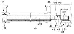
図1,図4Aに示すように回転部材47は長手軸a10に沿って操作部20の把持部21内に延出されている。回転部材47は駆動力受部44の軸方向貫通孔44hを通過し、駆動力受部44の基端面44fから長手軸a10方向に沿って予め定めた距離L、突出している。 As shown in FIGS. 1 and 4A, the rotating
図4Aの符号47mは磁石である。磁石47mは回転部材47の基端面に固設される。
回転部材47の中途部は回転伝達部47aである。駆動力受部44の回転は、軸方向貫通孔44hに設けられた貫通孔伝達部44aから回転伝達部47aに伝達されて回転部材47を回転させる。そして、回転部材47は回転伝達部47aの軸方向貫通孔44h内において軸方向に摺動自在に配置されている。 An intermediate portion of the rotating
ドライブシャフト46の外周面側には該ドライブシャフト46を保護するシース49が設けられている。シース49は電気絶縁性を有すると共に、耐摩耗性と可撓性とを備えた樹脂材で形成されている。シース49の基端側の端部は折れ止め24の先端側に固定されている。シース49の先端側の端部は可撓管14の先端側の予め定めた位置に固定されている。 A
符号50は検出装置である。本実施形態において検出装置50は磁気センサ51である。磁気センサ51は仕切り板27に固定されている。磁気センサ51は長手軸a10方向に沿って移動する磁石47mが磁気センサ51の破線で示す検出範囲a51内に位置するか否かを検出する。磁気センサ51は検出範囲a51内において磁石47mを検出したとき、検出信号を信号線51Lによってコントローラ7に伝送する。
可撓管14が図4Aに示すストレート状態のとき、磁石47mは磁気センサ51の検出範囲a51内に配置されるように規定されている。磁気センサ51は、磁石47mが検出範囲a51内に位置するとき、コントローラ7に検出信号を出力するようになっている。磁気センサ51の検出感度は磁石47mの大きさ(厚み等)を変更することで可能である。 When the
また、本実施形態において歯車部42は複数の歯車を配列したギア列である。モータ41の駆動力はモータ歯車41b,ギア列,駆動力受部44,伝達部材45の順で伝達されていく。ギア列に備えられた複数の歯車の歯車比を適宜設定して、伝達部材45が所定のトルクおよび所定の速度で駆動される。 Further, in this embodiment, the
なお、モータ41の種類、モータ41の制御方法によってはギア列を不要にすることが可能である。すなわち、モータ41の種類、あるいは、制御方法によっては、複数のギアを配列したギア列を用いることなく、モータ41の駆動力を一つの歯車、あるいは、直接、駆動力受部44に伝達して伝達部材45を駆動させることも可能である。 Depending on the type of the
上述に示した内視鏡システム1の作用を説明する。 The action of the endoscope system 1 described above will be described.
術者は内視鏡の挿入部本体11を管腔の入口から管腔内に挿入する。術者は挿入部本体11を挿入中、必要に応じてフットスイッチ8を操作する。 The operator inserts the insertion section
術者によって前進スイッチFが操作されると、コントローラ7によって磁気センサ51が動作状態になる。磁気センサ51は回転部材47に設けられた磁石47mを検知中、該センサ51からコントローラ7に検出信号を出力する。磁気センサ51からの検出信号を受けたコントローラ7はモータ駆動開始と判定し、モータ41を駆動させる制御を行う。 When the forward switch F is operated by the operator, the
すると、モータ41の出力軸41aが予め定められた方向に回転する。この出力軸41aの回転はモータ歯車41bから歯車部42に伝達され、歯車部42が有するギア列の後段歯車(図3の符号42e参照)から駆動力受部44に伝達され、この駆動力受部44が回転する。 Then, the
この駆動力受部44の回転に伴って回転部材47が回転し、回転部材47およびドライブシャフト46が回転する。ドライブシャフト46の回転は該シャフト46に設けられた駆動力出力部48に連結される被伝達部17に伝達される。この結果、スパイラルチューブ15が挿入部10の長手軸a10周りに予め定められた方向に回転する。 As the driving
スパイラルチューブ15が回転することによりフィン16も長手軸a10周りに回転する。回転するフィン16が管腔の内壁面に接触していると、該内壁面がフィン16により挿入部10の基端側に手繰り寄せられる。言い換えれば、挿入部10の先端部12が管腔の深部に向かって移動していく。 As the
スパイラルチューブ15の回転に伴って挿入部10が管腔の深部に挿入されていくと、挿入部本体11の可撓管14が管腔の曲がり状態に沿って湾曲される。 As the
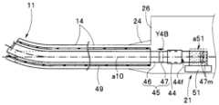
可撓管14がストレート状態から図4Bに示すような緩やかな角度で湾曲状態に変化すると伝達部材45が矢印Y4Bに示すように可撓管14内に僅かに引き込まれる。このとき、回転部材47に固設された磁石47mも破線に示す位置から長手軸a10に沿って駆動力受部44の基端面44f側の実線に示す位置に移動する。 When the
移動された磁石47mの位置が磁気センサ51の検出範囲a51内であるとき、磁気センサ51はコントローラ7に検出信号を出力し続ける。コントローラ7に磁気センサ51からの検出信号が入力されている間、コントローラ7は可撓管14の湾曲状態が規定範囲内であると判定してスパイラルチューブ15の回転を継続させる。 When the position of the moved
一方、可撓管14が図4Cに示すように図4Bの湾曲状態に比べて湾曲されている部分の湾曲角度の積算値が規定した値を越えて複雑に湾曲される、と、伝達部材45が矢印Y4Cに示すように可撓管14内に大きく引き込まれる。このとき、磁石47mが長手軸a10に沿って駆動力受部44の基端面44f側に移動されて磁気センサ51の検出範囲a51から外れ、磁気センサ51からコントローラ7への検出信号の出力が停止される。 On the other hand, as shown in FIG. 4C, the
磁気センサ51からコントローラ7への検出信号の出力が停止されると、モータ制御と判定していたコントローラ7はモータ駆動停止と判定してモータ41を停止させる制御に切り替わる。 When the output of the detection signal from the
本実施形態においてコントローラ7は、上述したように伝達部材45の回転部材47に固設した磁石47mが長手軸a10に沿って駆動力受部44の基端面44f側に引き込まれて磁気センサ51の検出範囲a51内から外れたとき、可撓管14の湾曲された角度の積算値が規定した値を越えて複雑に湾曲された、と判定して、トルクリミット機能を動作させてスパイラルチューブ15の回転を停止させる。 In the present embodiment, the
なお、術者によって後退スイッチBが操作されると、コントローラ7によって磁気センサ51を動作状態にすることなくモータ41の出力軸41aが前進スイッチFを操作したときとは反対方向に回転される。 When the backward switch B is operated by the operator, the
この出力軸41aの回転は上述したようにモータ歯車41bから歯車部42,ギア列の後段歯車42e,駆動力受部44,回転部材47,ドライブシャフト46に伝達される。そして、ドライブシャフト46の回転は上述したように駆動力出力部48から被伝達部17に伝達される。 The rotation of the
この結果、スパイラルチューブ15が挿入部10の長手軸a10周りに前進スイッチFを操作したときとは反対方向に回転する。このとき、フィン16もスパイラルチューブ15と共に回転する。そして、スパイラルチューブ15の回転状態において、フィン16が管腔の内壁面に接触状態であると、該内壁面がフィン16に絡められて挿入部10の先端側に手繰り寄せられる。言い換えれば、挿入部10の先端部12が管腔内を逆方向、すなわち、奥方から管腔の入口方向に向かって移動される。 As a result, the
上述した挿入部本体11の可撓管14の湾曲部13側にスパイラルチューブ15を配置した内視鏡1は、操作部20の把持部21内に固設した磁気センサ51と、該把持部21内で長手軸a10方向に摺動自在な伝達部材45に固設した磁石47mと、を配置したトルクリミット機能を備える。 The endoscope 1 in which the
磁気センサ51は、前進スイッチFを操作した状態において、磁石47mが磁気センサ51の検出範囲a51内に位置するとき、コントローラ7に検出信号を出力する。検出信号を受けたコントローラ7はモータ41の駆動を制御する。このモータ41を駆動させている状態において、磁石47mが磁気センサ51の検出範囲a51から外れると、コントローラ7への検出信号の出力が停止され、コントローラ7によるモータ41の駆動が停止され、スパイラルチューブ15の回転が停止する。 The
本実施形態の内視鏡1のトルクリミット機能は、操作部20の把持部21内に磁気センサ51と、該把持部21内で長手軸a10方向に摺動自在な伝達部材45に固設された磁石47mと、を配置している。したがって、トルクリミット機能のためのセンサおよび信号線を挿入部本体11内に設けることが不要である。したがって、挿入部本体11の外径が太径になる不具合が解消される。この結果、スパイラルチューブ15が配置される挿入部本体11の細径化を図ることができる。 The torque limit function of the endoscope 1 of the present embodiment is fixed to the
加えて、可撓管14の湾曲状態が変化すると伝達部材45の引き込まれる量が変化する。コントローラ7は伝達部材45が可撓管14内に引き込まれて基端に固設された磁石47mが磁気センサ51の検出範囲a51内から外れて検出信号の出力が停止されたとき、挿入部本体11の湾曲形状によらず可撓管14の湾曲状態が規定範囲を越えたと判定してトルクリミット機能を動作させる。 In addition, when the bending state of the
言い換えれば、引き込まれる伝達部材45に固設された磁石47mが磁気センサ51の検出範囲a51内であるときには、挿入部本体11の湾曲形状によらず伝達部材45からスパイラルチューブ15にモータ41の駆動力を伝達してスパイラルチューブ15を回転させて良好な挿入性能を維持できる。 In other words, when the
なお、上述した実施形態では磁石47mが磁気センサ51の検出範囲a51内に位置しているとき、磁気センサ51からコントローラ7に検出信号が出力されてモータ41を制御している。 In the above-described embodiment, when the
図4Dに示す磁気センサ51Aの検出範囲A51Aは長手軸a10に沿って複数の検出範囲a1,a2,a3を備えている。この磁気センサ51Aは各検出範囲a1,a2,a3毎に異なる検出信号をコントローラ7に出力する。コントローラ7は入力される検出信号毎にモータ41の駆動電流を予め設定されている電流値の駆動電流で制御する。 The detection range A51A of the
具体的に、可撓管14がストレート状態のとき実線に示す磁石47mは第1検出範囲a1内に位置する。上述したように前進スイッチFが操作されて磁気センサ51Aが動作状態になると、磁気センサ51Aから第1の検出信号がコントローラ7に出力される。第1の検出信号を受けたコントローラ7はモータ駆動と判定し、モータ41に予め定められた第1の駆動電流を供給してモータ41を駆動させる。 Specifically, when the
可撓管14が湾曲されていくと、破線に示すように磁石47mが長手軸a10に沿って第2検出範囲a2内に移動する。このとき、磁気センサ51Aから第2の検出信号がコントローラ7に出力される。第2の検出信号を受けたコントローラ7はモータ41の駆動力変更と判定し、モータ41に予め定められた第2の駆動電流を供給してモータ41を制御する。第2の駆動電流の電流値は第1の駆動電流の電流値より予め高く設定されている。 As the
さらに可撓管14が湾曲されると、二点鎖線に示すように磁石47mが長手軸a10に沿って第3検出範囲a3内に移動する。このとき、磁気センサ51Aから第3の検出信号がコントローラ7に出力される。第3の検出信号を受けたコントローラ7はモータ41の駆動力変更と判定し、モータ41に第2の駆動電流の電流値より予め高く設定した第3の駆動電流を供給してモータ41を制御する。 When the
そして、磁石47mが磁気センサ51Aの第3検出範囲a3から駆動力受部44の基端面44f側に外れたとき、磁気センサ51Aからコントローラ7への検出信号の出力が停止される。この結果、上述したようにコントローラ7は、モータ41を駆動させる制御からモータ41を停止させる制御に切り替わる。 When the
コントローラ7は磁気センサ51Aから出力される各種検出信号を受けて可撓管14の湾曲状態に対応する予め定めた駆動電流をモータ41に出力して該モータ41を制御する。この結果、スパイラルチューブ15は可撓管14の湾曲形状によらず可撓管14の湾曲状態に合わせて最適な駆動電流を受けて回転され、湾曲状態が規定範囲を越えたとき回転を停止する。 The
なお、磁気センサ51Aの検出範囲は3箇所に限定されるものでは無く、それ以上あるいは二つであってもよい。また、検出装置50は磁気センサ51,51Aに限定されるものでは無く、透過式、あるいは、反射式の光センサであってもよい。また、検出装置50は非接触式のセンサに限定されるものでは無く、マイクロスイッチを備えたリミットスイッチ等の接触式のスイッチであってもよい。 Note that the detection range of the
図5に示すようにドライブシャフト46の外周面側にシース49に替えてコイルシース49cを設けている。コイルシース49cは該ドライブシャフト46を保護する耐摩耗性と弾性力とを備えた非磁性体で形成されている。 As shown in FIG. 5, a
コイルシース49cの先端側の端部は可撓管14の先端側の予め定めた位置に固定されている。コイルシース49cの基端側の端部は折れ止め24の先端側に固定されている。弾性力を有するコイルシース49cは可撓管14が湾曲したときシース中心軸c49cの長さが湾曲量の増大に伴って長くなるようになっている。 The distal end of the
ドライブシャフト46は上述したように複数のワイヤ線を撚り合わせた撚り線である。撚り線であるドライブシャフト46は可撓管14が湾曲されとき、シャフト中心軸c46の長さ変化がほとんど無い。そして、可撓管14が直線状態において、シャフト中心軸c46とシース中心軸c49cとは長手軸a10に略一致している。 The
ドライブシャフト45の基端側に位置する回転部材47との接続部近傍には磁石46mが固設されている。符号51Bは磁気センサである。磁気センサ51Bは磁石46mの移動距離を非接触で検出する機能を有している。 A
磁気センサ51Bは三つの検出範囲を有する。点Oから点Aまでは第1検出範囲、点Aから点Bまでは第2検出範囲、点Bから点Cまでは第3検出範囲である。なお、検出範囲は三つに限定されるものでは無く、それ以上あるいはそれ以下であってもよい。上述したように磁気センサ51Bの検出感度の調整は磁石46mの大きさを変更することで可能である。 The
本実施形態において可撓管14がストレート状態のとき、磁石46mはコイルシース49cの基端に位置して第1の検出範囲内である。可撓管14がストレート状態から湾曲状態に変化していくと、シース中心軸c49cの長さがシャフト中心軸c46の長さに比べて長くなっていく。この結果、ドライブシャフト46に固定された磁石46mが長手軸a10に沿って破線に示すようにコイルシース49c内に引き込まれる。磁石46mの引き込まれる量、すなわち、移動距離は磁気センサ51Bで検出され、コントローラ7に出力される。 In this embodiment, when the
磁気センサ51Bは磁石46mが長手軸a10に沿って第1の検出範囲内に位置するとき第1の検出信号を出力し、第2の検出範囲内に位置するとき第2の検出信号を出力し、第3の検出範囲内に位置するとき第3の検出信号を出力する。そして、点Cを超えると検出信号の出力を停止する。 The
本実施形態においては可撓管14がストレート状態のとき、磁石46mは点Oと点Aとの間でコイルシース49cの基端に位置している。 In this embodiment, when the
前進スイッチFが操作されたときコントローラ7によって磁気センサ51Bが動作状態になる。磁気センサ51Bが動作されたとき、磁石46mが第1の検出範囲内に位置しているとき磁気センサ51Bから第1の検出信号がコントローラ7に出力される。一方、磁石46mが第2の検出範囲内に位置しているとき磁気センサ51Bから第2の検出信号がコントローラ7に出力される。 When the forward switch F is operated, the
検出信号を受けたコントローラ7は移動距離検出開始およびモータ駆動開始と判定する。コントローラ7は検出信号に対応する駆動電流である第1の駆動電流または第2の駆動電流をモータ41に供給してモータ41を駆動させる。 Upon receiving the detection signal, the
コイルシース49cが湾曲されると、矢印Y5に示すように磁石46mがコイルシース49c内に引き込まれていく。このときの磁石46mの長手軸a10方向への移動距離が磁気センサ51Bによって測定される。 When the
磁気センサ51Bは磁石46mがA点を越えるまで第1の検出信号をコントローラ7に出力し、B点を越えるまで第2の検出信号をコントローラ7に出力し、C点を越えるまで第3の検出信号をコントローラ7に出力する。 The
コントローラ7はモータ駆動状態において異なる検出信号が入力されたとき、モータ41の駆動力変更と判定し、駆動状態のモータ41に供給されていた駆動電流と異なる駆動電流を供給してモータ41を制御する。When a different detection signal is input in the motor driving state, the
そして、磁気センサ51Bは磁石46mがC点を超えたとき、磁気センサ51Bからコントローラ7への検出信号の出力を停止させる。この結果、コントローラ7は、モータ41を駆動させる制御からモータ41を停止させる制御に切り替わる。 The
この構成によれば、コントローラ7は磁気センサ51Bから出力される検出信号を受けてコイルシース49cと磁石46mの相対位置を判定して可撓管14の湾曲状態に関わらず最適な駆動電流をモータ41に出力して該モータ41を制御する。この結果、スパイラルチューブ15は可撓管14の湾曲形状によらずコイルシース49cの湾曲状態に合わせて最適な駆動電流で回転される。そして、磁石46mがC点を超えてコイルシース49cの湾曲形状が規定範囲を越えた湾曲角度に変形されたとき、あるいは、可撓管14が複雑に湾曲されたとき、回転を停止する。 According to this configuration, the
その他の構成は上述した実施形態と同様であり、同部材には同符号を付して説明を省略する。 The rest of the configuration is the same as in the above-described embodiment, and the same members are denoted by the same reference numerals, and descriptions thereof are omitted.
本発明は、上述した実施形態に限定されるものではなく、発明の要旨を逸脱しない範囲において種々変更あるいは応用が可能である。 The present invention is not limited to the above-described embodiments, and various modifications and applications are possible without departing from the scope of the invention.
Claims (15)
Translated fromJapanese前記可撓管の基端側に配置される駆動源と、
前記可撓管の先端部側に配置され、前記長手軸方向に移動可能な被駆動部材と、
前記可撓管内に挿通されており、該可撓管の基端側から当該可撓管の長手軸に沿って外部に延出される、前記駆動源の駆動力によって軸周りに回転され、該回転を前記被駆動部材に伝達する伝達部材と、
前記伝達部材の基端部における前記可撓管の長手軸に沿った位置を検出する検出装置と、
を具備することを特徴とする挿入装置。a flexible tube extending in the longitudinal direction and having flexibility;
a driving source disposed on the proximal end side of the flexible tube;
a driven member disposed on the distal end side of the flexible tube and movable in the longitudinal direction;
It is inserted into the flexible tube and extends outward along the longitudinal axis of the flexible tube from the proximal end side of the flexible tube. tothe driven member; and
a detection device for detecting the position of the proximalend of the transmission member along the longitudinal axis of the flexible tube;
An insertion device comprising:
前記可撓管の基端側に配置される駆動源と、
前記可撓管の先端部側に配置され、前記長手軸方向に移動可能な被駆動部材と、
前記可撓管内に挿通されており、該可撓管の基端側から当該可撓管の長手軸に沿って外部に延出される、前記駆動源の駆動力によって軸周りに回転され、該回転を前記被駆動部材に伝達することで前記被駆動部材を前記長手軸方向に移動させる伝達部材と、
前記伝達部材の外周を覆うように配置されるシースと、
前記シースの基端部と前記伝達部材の基端部との前記可撓管の長手軸方向に沿った相対位置を検出する検出装置と、
を具備することを特徴とする挿入装置。a flexible tube extending in the longitudinal direction and having flexibility;
a driving source disposed on the proximal end side of the flexible tube;
a driven member disposed on the distal end side of the flexible tube and movable in the longitudinal direction;
It is inserted into the flexible tube and extends outward along the longitudinal axis of the flexible tube from the proximal end side of the flexible tube. tothe driven member to move the driven member in the longitudinal direction;
a sheath arranged to cover the outer periphery of the transmission member;
a detection device for detecting relative positionsof the proximal end of the sheath and the proximalend of the transmission member along the longitudinal direction of the flexible tube;
An insertion device comprising:
前記伝達部材の基端側における長手軸方向の位置は前記可撓管に対して変位可能であることを特徴とする請求項7に記載の挿入装置。a proximal longitudinal position of the sheath is fixed with respect to the flexible tube;
8. The insertion device of claim7 , wherein the proximal longitudinal position of the transmission member is displaceable with respect to the flexible tube.
Applications Claiming Priority (1)
| Application Number | Priority Date | Filing Date | Title |
|---|---|---|---|
| PCT/JP2020/009827WO2021176719A1 (en) | 2020-03-06 | 2020-03-06 | Insertion device |
Publications (3)
| Publication Number | Publication Date |
|---|---|
| JPWO2021176719A1 JPWO2021176719A1 (en) | 2021-09-10 |
| JPWO2021176719A5 JPWO2021176719A5 (en) | 2022-08-09 |
| JP7259129B2true JP7259129B2 (en) | 2023-04-17 |
Family
ID=77613993
Family Applications (1)
| Application Number | Title | Priority Date | Filing Date |
|---|---|---|---|
| JP2022504941AActiveJP7259129B2 (en) | 2020-03-06 | 2020-03-06 | insertion device |
Country Status (4)
| Country | Link |
|---|---|
| US (1) | US20220409027A1 (en) |
| JP (1) | JP7259129B2 (en) |
| CN (1) | CN115103621A (en) |
| WO (1) | WO2021176719A1 (en) |
Citations (3)
| Publication number | Priority date | Publication date | Assignee | Title |
|---|---|---|---|---|
| WO2005110191A1 (en) | 2004-05-13 | 2005-11-24 | Olympus Corporation | Insertion device |
| JP2007319547A (en) | 2006-06-02 | 2007-12-13 | Olympus Medical Systems Corp | Rotating self-propelled endoscope system |
| WO2014003064A1 (en) | 2012-06-27 | 2014-01-03 | オリンパスメディカルシステムズ株式会社 | Insertion device |
Family Cites Families (2)
| Publication number | Priority date | Publication date | Assignee | Title |
|---|---|---|---|---|
| US5060632A (en)* | 1989-09-05 | 1991-10-29 | Olympus Optical Co., Ltd. | Endoscope apparatus |
| EP3005932A4 (en)* | 2013-05-30 | 2017-03-29 | Olympus Corporation | Insertion device |
- 2020
- 2020-03-06WOPCT/JP2020/009827patent/WO2021176719A1/ennot_activeCeased
- 2020-03-06JPJP2022504941Apatent/JP7259129B2/enactiveActive
- 2020-03-06CNCN202080096380.7Apatent/CN115103621A/enactivePending
- 2022
- 2022-08-31USUS17/899,691patent/US20220409027A1/enactivePending
Patent Citations (3)
| Publication number | Priority date | Publication date | Assignee | Title |
|---|---|---|---|---|
| WO2005110191A1 (en) | 2004-05-13 | 2005-11-24 | Olympus Corporation | Insertion device |
| JP2007319547A (en) | 2006-06-02 | 2007-12-13 | Olympus Medical Systems Corp | Rotating self-propelled endoscope system |
| WO2014003064A1 (en) | 2012-06-27 | 2014-01-03 | オリンパスメディカルシステムズ株式会社 | Insertion device |
Also Published As
| Publication number | Publication date |
|---|---|
| CN115103621A (en) | 2022-09-23 |
| US20220409027A1 (en) | 2022-12-29 |
| JPWO2021176719A1 (en) | 2021-09-10 |
| WO2021176719A1 (en) | 2021-09-10 |
Similar Documents
| Publication | Publication Date | Title |
|---|---|---|
| EP2668885B1 (en) | Endoscope | |
| US8075474B2 (en) | Endoscope system and medical instrument | |
| US10736493B2 (en) | Inserting device | |
| US7914440B2 (en) | Endoscope | |
| JP7560133B2 (en) | Insertion unit for medical instrument and intubation system thereof | |
| US10258223B2 (en) | Inserting instrument, rotary unit and inserting apparatus | |
| US8974376B2 (en) | Introducing device system with bending control | |
| JP6615228B2 (en) | Flexible tube insertion device | |
| JP6218992B2 (en) | Insertion device | |
| JP3549434B2 (en) | Electric curved endoscope | |
| JP4624714B2 (en) | Endoscope | |
| US9603507B2 (en) | Insertion device | |
| EP1649799A1 (en) | Endoscope | |
| JP6177485B1 (en) | Manipulator system | |
| JP7259129B2 (en) | insertion device | |
| JP3283115B2 (en) | Endoscope | |
| JP3934593B2 (en) | Endoscope system | |
| JP2020031844A (en) | Tip rotation catheter | |
| JP3706229B2 (en) | Endoscope device | |
| JPWO2021176719A5 (en) | ||
| JP2020043907A (en) | Endoscope |
Legal Events
| Date | Code | Title | Description |
|---|---|---|---|
| A521 | Request for written amendment filed | Free format text:JAPANESE INTERMEDIATE CODE: A523 Effective date:20220613 | |
| A621 | Written request for application examination | Free format text:JAPANESE INTERMEDIATE CODE: A621 Effective date:20220613 | |
| A131 | Notification of reasons for refusal | Free format text:JAPANESE INTERMEDIATE CODE: A131 Effective date:20230207 | |
| A521 | Request for written amendment filed | Free format text:JAPANESE INTERMEDIATE CODE: A523 Effective date:20230302 | |
| TRDD | Decision of grant or rejection written | ||
| A01 | Written decision to grant a patent or to grant a registration (utility model) | Free format text:JAPANESE INTERMEDIATE CODE: A01 Effective date:20230328 | |
| A61 | First payment of annual fees (during grant procedure) | Free format text:JAPANESE INTERMEDIATE CODE: A61 Effective date:20230405 | |
| R151 | Written notification of patent or utility model registration | Ref document number:7259129 Country of ref document:JP Free format text:JAPANESE INTERMEDIATE CODE: R151 |