JP7258202B2 - Closed system stress resistant membrane - Google Patents
Closed system stress resistant membraneDownload PDFInfo
- Publication number
- JP7258202B2 JP7258202B2JP2022073280AJP2022073280AJP7258202B2JP 7258202 B2JP7258202 B2JP 7258202B2JP 2022073280 AJP2022073280 AJP 2022073280AJP 2022073280 AJP2022073280 AJP 2022073280AJP 7258202 B2JP7258202 B2JP 7258202B2
- Authority
- JP
- Japan
- Prior art keywords
- membrane
- central axis
- distal portion
- distal
- well
- Prior art date
- Legal status (The legal status is an assumption and is not a legal conclusion. Google has not performed a legal analysis and makes no representation as to the accuracy of the status listed.)
- Active
Links
Images


Classifications
- A—HUMAN NECESSITIES
- A61—MEDICAL OR VETERINARY SCIENCE; HYGIENE
- A61J—CONTAINERS SPECIALLY ADAPTED FOR MEDICAL OR PHARMACEUTICAL PURPOSES; DEVICES OR METHODS SPECIALLY ADAPTED FOR BRINGING PHARMACEUTICAL PRODUCTS INTO PARTICULAR PHYSICAL OR ADMINISTERING FORMS; DEVICES FOR ADMINISTERING FOOD OR MEDICINES ORALLY; BABY COMFORTERS; DEVICES FOR RECEIVING SPITTLE
- A61J1/00—Containers specially adapted for medical or pharmaceutical purposes
- A61J1/14—Details; Accessories therefor
- A61J1/20—Arrangements for transferring or mixing fluids, e.g. from vial to syringe
- A61J1/2003—Accessories used in combination with means for transfer or mixing of fluids, e.g. for activating fluid flow, separating fluids, filtering fluid or venting
- A61J1/202—Separating means
- A61J1/2044—Separating means having slits
- A—HUMAN NECESSITIES
- A61—MEDICAL OR VETERINARY SCIENCE; HYGIENE
- A61J—CONTAINERS SPECIALLY ADAPTED FOR MEDICAL OR PHARMACEUTICAL PURPOSES; DEVICES OR METHODS SPECIALLY ADAPTED FOR BRINGING PHARMACEUTICAL PRODUCTS INTO PARTICULAR PHYSICAL OR ADMINISTERING FORMS; DEVICES FOR ADMINISTERING FOOD OR MEDICINES ORALLY; BABY COMFORTERS; DEVICES FOR RECEIVING SPITTLE
- A61J1/00—Containers specially adapted for medical or pharmaceutical purposes
- A61J1/14—Details; Accessories therefor
- A61J1/1406—Septums, pierceable membranes
- A—HUMAN NECESSITIES
- A61—MEDICAL OR VETERINARY SCIENCE; HYGIENE
- A61J—CONTAINERS SPECIALLY ADAPTED FOR MEDICAL OR PHARMACEUTICAL PURPOSES; DEVICES OR METHODS SPECIALLY ADAPTED FOR BRINGING PHARMACEUTICAL PRODUCTS INTO PARTICULAR PHYSICAL OR ADMINISTERING FORMS; DEVICES FOR ADMINISTERING FOOD OR MEDICINES ORALLY; BABY COMFORTERS; DEVICES FOR RECEIVING SPITTLE
- A61J1/00—Containers specially adapted for medical or pharmaceutical purposes
- A61J1/14—Details; Accessories therefor
- A61J1/20—Arrangements for transferring or mixing fluids, e.g. from vial to syringe
- A61J1/2003—Accessories used in combination with means for transfer or mixing of fluids, e.g. for activating fluid flow, separating fluids, filtering fluid or venting
- A61J1/2006—Piercing means
- A61J1/201—Piercing means having one piercing end
- A—HUMAN NECESSITIES
- A61—MEDICAL OR VETERINARY SCIENCE; HYGIENE
- A61J—CONTAINERS SPECIALLY ADAPTED FOR MEDICAL OR PHARMACEUTICAL PURPOSES; DEVICES OR METHODS SPECIALLY ADAPTED FOR BRINGING PHARMACEUTICAL PRODUCTS INTO PARTICULAR PHYSICAL OR ADMINISTERING FORMS; DEVICES FOR ADMINISTERING FOOD OR MEDICINES ORALLY; BABY COMFORTERS; DEVICES FOR RECEIVING SPITTLE
- A61J1/00—Containers specially adapted for medical or pharmaceutical purposes
- A61J1/14—Details; Accessories therefor
- A61J1/20—Arrangements for transferring or mixing fluids, e.g. from vial to syringe
- A61J1/2003—Accessories used in combination with means for transfer or mixing of fluids, e.g. for activating fluid flow, separating fluids, filtering fluid or venting
- A61J1/2048—Connecting means
- A—HUMAN NECESSITIES
- A61—MEDICAL OR VETERINARY SCIENCE; HYGIENE
- A61J—CONTAINERS SPECIALLY ADAPTED FOR MEDICAL OR PHARMACEUTICAL PURPOSES; DEVICES OR METHODS SPECIALLY ADAPTED FOR BRINGING PHARMACEUTICAL PRODUCTS INTO PARTICULAR PHYSICAL OR ADMINISTERING FORMS; DEVICES FOR ADMINISTERING FOOD OR MEDICINES ORALLY; BABY COMFORTERS; DEVICES FOR RECEIVING SPITTLE
- A61J1/00—Containers specially adapted for medical or pharmaceutical purposes
- A61J1/14—Details; Accessories therefor
- A61J1/20—Arrangements for transferring or mixing fluids, e.g. from vial to syringe
- A61J1/2096—Combination of a vial and a syringe for transferring or mixing their contents
- A—HUMAN NECESSITIES
- A61—MEDICAL OR VETERINARY SCIENCE; HYGIENE
- A61M—DEVICES FOR INTRODUCING MEDIA INTO, OR ONTO, THE BODY; DEVICES FOR TRANSDUCING BODY MEDIA OR FOR TAKING MEDIA FROM THE BODY; DEVICES FOR PRODUCING OR ENDING SLEEP OR STUPOR
- A61M5/00—Devices for bringing media into the body in a subcutaneous, intra-vascular or intramuscular way; Accessories therefor, e.g. filling or cleaning devices, arm-rests
- A61M5/14—Infusion devices, e.g. infusing by gravity; Blood infusion; Accessories therefor
- A61M5/1413—Modular systems comprising interconnecting elements
- A—HUMAN NECESSITIES
- A61—MEDICAL OR VETERINARY SCIENCE; HYGIENE
- A61J—CONTAINERS SPECIALLY ADAPTED FOR MEDICAL OR PHARMACEUTICAL PURPOSES; DEVICES OR METHODS SPECIALLY ADAPTED FOR BRINGING PHARMACEUTICAL PRODUCTS INTO PARTICULAR PHYSICAL OR ADMINISTERING FORMS; DEVICES FOR ADMINISTERING FOOD OR MEDICINES ORALLY; BABY COMFORTERS; DEVICES FOR RECEIVING SPITTLE
- A61J1/00—Containers specially adapted for medical or pharmaceutical purposes
- A61J1/14—Details; Accessories therefor
- A61J1/20—Arrangements for transferring or mixing fluids, e.g. from vial to syringe
- A—HUMAN NECESSITIES
- A61—MEDICAL OR VETERINARY SCIENCE; HYGIENE
- A61M—DEVICES FOR INTRODUCING MEDIA INTO, OR ONTO, THE BODY; DEVICES FOR TRANSDUCING BODY MEDIA OR FOR TAKING MEDIA FROM THE BODY; DEVICES FOR PRODUCING OR ENDING SLEEP OR STUPOR
- A61M5/00—Devices for bringing media into the body in a subcutaneous, intra-vascular or intramuscular way; Accessories therefor, e.g. filling or cleaning devices, arm-rests
- A61M5/14—Infusion devices, e.g. infusing by gravity; Blood infusion; Accessories therefor
- A61M5/162—Needle sets, i.e. connections by puncture between reservoir and tube ; Connections between reservoir and tube
Landscapes
- Health & Medical Sciences (AREA)
- Life Sciences & Earth Sciences (AREA)
- Animal Behavior & Ethology (AREA)
- General Health & Medical Sciences (AREA)
- Public Health (AREA)
- Veterinary Medicine (AREA)
- Pharmacology & Pharmacy (AREA)
- Physics & Mathematics (AREA)
- Fluid Mechanics (AREA)
- Engineering & Computer Science (AREA)
- Vascular Medicine (AREA)
- Anesthesiology (AREA)
- Biomedical Technology (AREA)
- Heart & Thoracic Surgery (AREA)
- Hematology (AREA)
- Infusion, Injection, And Reservoir Apparatuses (AREA)
- Medical Preparation Storing Or Oral Administration Devices (AREA)
- Registering, Tensioning, Guiding Webs, And Rollers Therefor (AREA)
- Sealing Devices (AREA)
- Superconductors And Manufacturing Methods Therefor (AREA)
- Surgical Instruments (AREA)
Description
Translated fromJapanese本開示は、一般に、流体の閉鎖系移送のためのシステムに関する。より詳細には、本開示は、第1の容器または装置から第2の容器または装置への流体移送中に漏れ止めシール作用を提供する応力抵抗膜を有する、流体の閉鎖式移送のためのシステムに関する。 The present disclosure relates generally to systems for closed-system transfer of fluids. More particularly, the present disclosure provides a system for closed transfer of fluids having a stress resistant membrane that provides a leak tight seal during fluid transfer from a first container or device to a second container or device. Regarding.
関連出願の相互参照Cross-reference to related applications
本出願は、参照によりその全体的開示が本明細書に組み込まれている、「Closed System Stress Resistant Membrane」と題する、2017年1月12日出願の米国特許仮出願第62/445,393号明細書の優先権を主張するものである。 This application is the subject of U.S. Provisional Application No. 62/445,393, entitled "Closed System Stress Resistant Membrane," filed Jan. 12, 2017, the entire disclosure of which is incorporated herein by reference. The priority of the document is claimed.
がん治療薬剤などの危険な薬剤を再構成し、輸送し、投与する医療提供者は、これらの薬剤への露出というリスクにさらされ、医療環境において重大な危険を有する可能性がある。たとえば、がん患者を治療する看護師は、化学療法薬およびその有毒作用にさらされるリスクを有する。意図せず化学療法薬にさらされると、神経系に影響が及び、生殖器系を損ない、将来的に血液がんを発症するリスクの増大をもたらす可能性がある。有毒薬物にさらされる医療提供者のリスクを低減するために、再構成、輸送、および投与中のこれらの薬物の閉鎖式移送が重要になってきている。 Health care providers who reconstitute, transport, and administer hazardous drugs, such as cancer drugs, are at risk of exposure to these drugs and can pose significant risks in the healthcare setting. For example, nurses who treat cancer patients are at risk of exposure to chemotherapy drugs and their toxic effects. Unintentional exposure to chemotherapy drugs can affect the nervous system, damage the reproductive system, and increase the risk of developing blood cancers in the future. Closed transport of these drugs during reconstitution, transport, and administration has become important to reduce the risk of health care providers' exposure to toxic drugs.
いくつかの薬物は、これらが投与される前に溶解または希釈されなければならず、これは、針を用いて、第1の容器から、粉末または液体の形の薬物を含むシールされたバイアルなどの第2の容器に溶剤を移送することを伴う。薬物は、バイアルからの針の引き出し中、およびバイアルの内部と周囲の大気との間に圧力差が存在する場合に針がバイアルの内側にある間、ガスの形でまたはエアロゾル化によって気付かないうちに大気に放出されることがある。 Some drugs must be dissolved or diluted before they can be administered, such as a sealed vial containing the drug in powder or liquid form, from a first container using a needle. and transferring the solvent to a second container of . The drug is unnoticed in gas form or by aerosolization during withdrawal of the needle from the vial and while the needle is inside the vial when a pressure difference exists between the interior of the vial and the surrounding atmosphere. may be released into the atmosphere over time.
第1の容器から第2の容器への流体移送中に漏れ止めシール作用を提供する流体の閉鎖式移送のためのシステムを提供することが、有利となる。 It would be advantageous to provide a system for closed transfer of fluids that provides a leak tight seal during transfer of fluids from a first container to a second container.
本開示は、第1の容器から第2の容器への流体の閉鎖式移送のためのシステムを提供する。システムは、第1の容器から第2の容器への流体移送中に漏れ止めシール作用を提供する応力抵抗膜を有する。 The present disclosure provides a system for closed transfer of fluid from a first container to a second container. The system has a stress resistant membrane that provides a leaktight seal during fluid transfer from the first container to the second container.
いくつかの例では、閉鎖系移送装置に関連して使用するための膜は、中央軸に沿って遠位部分の反対側に近位部分を備えた本体と、近位部分と遠位部分との間の移行部にへり部が形成されるように遠位部分から径方向に外方向に延びるスカートとを有することができる。膜は、遠位部分内に窪められ、遠位部分の遠位端部から近位方向に延びる、少なくとも1つのウエルをさらに有することができ、それによって遠位部分内にチャネルを形成する。チャネルは、開放された第1の端部と、閉鎖された底部の端部と、その第1の端部と第2の端部との間を延びる側壁の対とを有することができる。少なくとも1つのスリットが、本体の少なくとも一部分を通って、中央軸に沿ってまたは平行に位置合わせされた平面の方向に延びることができる。 In some examples, a membrane for use in connection with a closed system delivery device includes a body with a proximal portion opposite a distal portion along a central axis; and a skirt extending radially outwardly from the distal portion such that a lip is formed at the transition between. The membrane can further have at least one well recessed within the distal portion and extending proximally from the distal end of the distal portion, thereby forming a channel within the distal portion. The channel may have an open first end, a closed bottom end, and a pair of sidewalls extending between the first and second ends thereof. At least one slit can extend through at least a portion of the body in the direction of a plane aligned along or parallel to the central axis.
他の例では、少なくとも1つのウエルは、中央軸周りで円周方向に連続することができる。少なくとも1つのウエルは、中央軸周りで円周方向に不連続になることができる。少なくとも1つのウエルは、環状形状を有することができる。少なくとも1つのウエルは、複数のウエルを有することができ、各ウエルは、中央軸から異なる半径を離して位置決めされる。少なくとも1つのウエルは、中央軸から同じ半径を離して位置決めされ、少なくとも1つの連結リブによって互いから分離される、複数のウエルを有することができる。 In other examples, at least one well can be circumferentially continuous about a central axis. At least one well can be circumferentially discontinuous about the central axis. At least one well can have an annular shape. The at least one well may have multiple wells, each well positioned a different radius away from the central axis. The at least one well can have a plurality of wells positioned the same radius apart from the central axis and separated from each other by at least one connecting rib.
他の例では、少なくとも1つのスリットは、本体の遠位部分の少なくとも一部分を通って、中央軸に沿う方向に延びることができる。少なくとも1つのスリットは、膜を通るカニューレの貫通中にカニューレによって開かれ、膜からのカニューレの引き出しのときに閉じるように構成され得る。少なくとも1つのスリットは、遠位端部の遠位部分から遠位に突起する隆起領域上に位置決めされ得る。隆起領域は、膜の中央軸上に頂点を備えて弓状に成形され得る。少なくとも1つのスリットは、各スリットの中点において互いと交差するスリットの対であってよい。少なくとも1つのスリットは、その端点の1つにおいて互いに連結された3つのスリットであってよい。スリットは、垂直角度で交差することができる。スリットは、カニューレがスリットの交差点を通ってスリットを貫通するように配置され得る。 Alternatively, the at least one slit can extend through at least a portion of the distal portion of the body in a direction along the central axis. The at least one slit may be configured to be opened by the cannula during penetration of the cannula through the membrane and closed upon withdrawal of the cannula from the membrane. At least one slit may be positioned on the raised region projecting distally from the distal portion of the distal end. The raised region may be arcuately shaped with an apex on the central axis of the membrane. The at least one slit may be a pair of slits that intersect each other at the midpoint of each slit. The at least one slit may be three slits connected together at one of its endpoints. The slits can intersect at a vertical angle. The slits may be arranged so that the cannula passes through the slit through the intersection of the slits.
他の例では、保持リングが、遠位端部の遠位部分から遠位方向に突起することができる。保持リングは、中央軸周りで円周方向に連続することができる。保持リングは、中央軸周りで円周方向に不連続になることができる。保持リングは、環状形状を有することができる。近位部分および遠位部分は、一緒になって一枚板状に形成され得る。本体は、中央軸周りで線対称になり得る。へり部は、中央軸に対して実質的に垂直になり得る。近位部分の近位端部は、凸状表面または平面状表面を有することができる。遠位部分の遠位端部は、凸状表面または平面状表面を有することができる。近位部分の外周は、放射状縁を有することができる。 Alternatively, a retaining ring can project distally from a distal portion of the distal end. The retaining ring can be circumferentially continuous about a central axis. The retaining ring can be circumferentially discontinuous about the central axis. The retaining ring can have an annular shape. The proximal portion and the distal portion may be formed together in one piece. The body can be axisymmetric about a central axis. The lip can be substantially perpendicular to the central axis. The proximal end of the proximal portion can have a convex surface or a planar surface. The distal end of the distal portion can have a convex surface or a planar surface. The circumference of the proximal portion can have radial edges.
他の例では、流体の閉鎖式移送のためのシステムは、第1の端部および第2の端部を有し、第1の端部は第1の容器に固定されるように構成される、ハウジングを含むシリンジアダプタと、第1の端部および第2の端部を有し、第2の端部はハウジング内に位置決めされる、カニューレと、膜であって、中央軸に沿って遠位部分の反対側に近位部分を備えた本体と、近位部分と遠位部分との間の移行部にへり部が形成されるように遠位端部から径方向に外方向に延びるスカートとを有する、膜とを有することができる。膜は、遠位部分の遠位端部から近位方向に窪められた少なくとも1つのウエルを有することができ、それによって遠位部分内に、開放された第1の端部と、閉鎖された底部の端部と、その第1の端部と第2の端部との間を延びる側壁の対とを有するチャネルを形成する。膜は、本体の少なくとも一部分を通って、中央軸に沿う方向に延びる少なくとも1つのスリットを有することができる。システムは、第2の膜を有する第2の構成要素をさらに有することができる。 In another example, a system for closed transfer of fluid has a first end and a second end, the first end configured to be secured to a first container. a syringe adapter including a housing; a cannula having a first end and a second end, the second end being positioned within the housing; and a membrane extending distally along a central axis. a body having a proximal portion opposite a proximal portion and a skirt extending radially outwardly from the distal end such that a lip is formed at the transition between the proximal and distal portions; and a membrane. The membrane can have at least one well recessed proximally from the distal end of the distal portion, thereby forming an open first end and a closed well within the distal portion. forming a channel having a flat bottom end and a pair of sidewalls extending between its first and second ends. The membrane can have at least one slit extending through at least a portion of the body in a direction along the central axis. The system can further have a second component with a second membrane.
添付の図を併用して本開示の例の以下の説明を参照することにより、本開示の上記で述べた、および他の特徴および利点、ならびにこれらを達成する方法がより良好に明らかになり、開示自体がより良好に理解されるであろう。 The above-mentioned and other features and advantages of the disclosure, as well as methods of achieving them, will become better apparent by reference to the following description of examples of the disclosure in conjunction with the accompanying figures, The disclosure itself will be better understood.
対応する参照記号は、複数の図にわたって対応する部分を示す。本明細書に記載する例証は、本開示の例示的な例を示すものであり、そのような例証は、本開示の範囲をいかなる形においても限定すると解釈されるものではない。 Corresponding reference characters indicate corresponding parts throughout the figures. The exemplifications set forth herein provide illustrative examples of the disclosure and such exemplifications are not to be construed as limiting the scope of the disclosure in any way.
以下の説明は、本発明を実施するように企図された、説明する例を当業者が作製し、使用できるように提供される。しかし、さまざまな改変形態、等価物、変形形態、および代替策が、依然として当業者に明らかであろう。あらゆるすべてのそのような改変形態、変形形態、等価物、および代替策は、本発明の趣旨および範囲内に入るように意図される。 The following description is provided to enable any person skilled in the art to make and use illustrative examples designed to practice the present invention. However, various modifications, equivalents, variations and alternatives will still be apparent to those skilled in the art. Any and all such modifications, variations, equivalents, and alternatives are intended to come within the spirit and scope of the present invention.
これ以後の説明のために、用語「上側」、「下側」、「右」、「左」、「垂直」、「水平」、「上部」、「底部」、「横方向」、「長手方向」、およびこれらの派生語は、これが図内に配向されるように本発明に関連づけるものとする。しかし、そうではないと明らかに明示される場合を除き、本発明がさまざまな代替の変形形態をとり得ることを理解されたい。また、添付の図に示し、以下の明細書において説明する特有の装置は、本発明の例示的な例にすぎないことも理解されたい。故に、本明細書に開示する例に関連づけられる特有の寸法および他の物理的特徴は、限定的であると解釈されるものではない。 For the purposes of the discussion hereafter, the terms "upper", "lower", "right", "left", "vertical", "horizontal", "top", "bottom", "transverse", "longitudinal" , and derivatives thereof shall relate to the present invention as it is oriented in the figures. However, it is to be understood that the invention is susceptible to various alternative variations, except where expressly stated to the contrary. It is also to be understood that the specific devices shown in the accompanying drawings and described in the following specification are merely illustrative examples of the invention. Therefore, specific dimensions and other physical characteristics associated with the examples disclosed herein are not to be construed as limiting.
本明細書および特許請求の範囲では、「1つ(a)」、「1つ(an)」、および「その」の単数形は、内容が別途明確に定めない限り、複数の指示対象を含む。 In this specification and claims, the singular forms "a," "an," and "the" include plural referents unless the content clearly dictates otherwise. .
別途示されない限り、「近位」は、患者から離れるか、または最も遠くに、かつ治療者に向かうか、または最も近くに位置する部分または方向(上流側)を指し、その一方で遠位は、患者に向かうか、または最も近くに位置し、かつ治療者から離れるか、またはより遠くにある部分または方向(下流側)を指すものとする。また、薬物物質は、本明細書では、任意の目的で患者の体内に注射可能である任意の物質を示すために説明上の非限定な形で使用される。患者への参照は、人または動物の任意の生き物に対するものになり得る。治療者への参照は、たとえば看護師、医師、機械知能、介護士などの治療を与える任意の人もしくは物、または自己治療に対するものにもなり得る。 Unless otherwise indicated, "proximal" refers to the portion or direction located furthest away from the patient and toward or closest to the therapist (upstream), while distal , toward or closest to the patient and away or farther away from the therapist (downstream). Drug substance is also used herein in a descriptive, non-limiting manner to refer to any substance that can be injected into a patient's body for any purpose. References to patients can be to any living creature, human or animal. A reference to a therapist can also be to any person or thing that provides treatment, such as a nurse, doctor, machine intelligence, caregiver, or to self-treatment.
別途示されない限り、本明細書および/または特許請求の範囲に使用する数量を表すすべての数字は、すべての場合において用語「約」によって修飾されると理解されるものである。 Unless otherwise indicated, all numbers expressing quantities used in the specification and/or claims are to be understood as being modified in all instances by the term "about."
図1A~5Bを参照すると、本開示は、流体の閉鎖式移送のためのさまざまなシステム10を対象とする。図1A~5Bを参照して本明細書の説明する各例では、システム10は、第1の容器または装置から第2の容器または装置への流体移送中に漏れ止めシール作用を提供する応力抵抗膜を含む。各例では、システム10は、バイアルなどの第1の容器または装置からシリンジ、IVバッグ、または患者IVラインなどの第2の容器または装置への流体の移送中、実質的に漏れ止めシール作用を提供する。システム10のさまざまな例の漏れ止めシール作用は、システム10の使用中、ガスおよび液体の両方の漏れを実質的に防止する。 1A-5B, the present disclosure is directed to
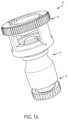
図1A~1Bを参照すれば、流体の閉鎖式移送のためのシステム10の1つの例は、薬物移送手順中にわたって漏れ止めシールを提供するコネクタ12を含む。コネクタ12のさまざまな態様は、参照において全体的に本明細書に組み込まれている、特許文献1に説明される。 Referring to FIGS. 1A-1B, one example of a
図1A~1Bを参照すれば、コネクタ12の1つの例は、患者の血流に挿入された静脈注射用ライン(図示せず)に連結するように構成される。1つの実施形態では、コネクタ12は、ニュージャージー州、フランクリンレイクスのBecton、Dickinson and Companyから入手可能なBecton Dickinson PhaSeal(商標)Systemに適合可能なPhaSeal(商標)コネクタを備える。他の実施形態では、コネクタ12は、他の閉鎖系薬物移送装置に適合可能なコネクタを備える。 1A-1B, one example of
引き続き図1A~1Bを参照すると、コネクタ12は、ルアータイプ継手などによって静脈注射用ラインに連結するように構成された遠位端部14を有する。コネクタ12の近位端部16は、注射器からの薬物が患者に送達され得るように注射器(図示せず)に連結するように構成される。コネクタ12は、遠位端部14と近位端部16との間に通路18(図1Bに示す)を画定する。通路18は、図1Bに示すように実質的に線形になり得る。図2に示すようないくつかの例では、通路18は、L字形状にされ得る。さまざまな他の例では、通路18および/またはコネクタ12の全体形状は、任意の他の形状を有することができる。 With continued reference to FIGS. 1A-1B,
コネクタ12は、通路18内に位置決めされたシール配置をさらに含む。シール配置は、膜34を含む。いくつかの例では、膜34は、通路18を横切って延び、通路18内で移動しないように軸方向に保持される。膜34は、近位部分102および遠位部分104を有する本体100を含む。
図1Bを参照すれば、膜34は、遠位端部14と近位端部16との間の膜シート20内に保持される。膜34は、膜34の近位部分102の少なくとも一部分と係合するへり部22によって膜シート20内に保持される。注射器の針(図示せず)は、薬物移送手順中、膜34を通って近位端部102から遠位端部104に向かって延びるように構成される。カニューレの遠位端部は、膜34を穿孔し、膜34を通って延びるように構成される。膜34は、カニューレの中間部分と係合し、これをシールして、コネクタ12と注射器との間にシールされた漏れのない連結を維持するように構成される。本明細書に論じるさまざまな例では、膜34は、針の貫通後の再シール作用の品質を改善するように構成された特徴を有する。加えて、本明細書に論じる膜34のさまざまな例は、コアリング(カニューレ貫通中の粒子の発生)を最小限に抑えるように構成された特徴を有する。 Referring to FIG. 1B,
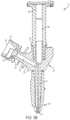
図3A~3Bを参照すれば、流体の閉鎖式移送のためのシステム10の1つの例は、薬物移送手順において使用するために漏れ止め式に静脈注射用バッグに固定して連結するように構成された注入アダプタ24を含む。注入アダプタ24のさまざまな態様は、参照において全体的に本明細書に組み込まれている、特許文献2に説明される。1つの例では、注入アダプタ24は、ニュージャージー州、フランクリンレイクスのBecton、Dickinson and Companyから入手可能なBecton Dickinson PhaSeal(商標)Systemに適合可能であるPhaSealコネクタを有する。他の実施形態では、注入アダプタ24は、他の閉鎖系薬物移送装置に適合可能であるコネクタを備える。 3A-3B, one example of a
引き続き図3A~3Bを参照すると、注入アダプタ24は、遠位端部28に位置する連結部分26と、第1のポート端部32に位置する第1のポート30と、第2のポート端部36に位置する第2のポート35とを含む。連結部分26は、アンカー構成要素と、流体チャネル40(図3Bに示す)とを含む。図3Bを参照すると、第1のポート30は第1のポート流体チャネル42を含み、第2のポート35は第2のポート流体チャネル44を含む。連結部分26の流体チャネル40は、第1のポート30の第1のポート流体チャネル42と流体連通しており、それにより、流体は第1のポート30において注入アダプタ24内に流れ、第1のポート流体チャネル42を通って連結部分26の流体チャネル40まで進行し、注入アダプタ24の遠位端部28から出ることができる。連結部分26の流体チャネル40は、第2のポート35の第2のポート流体チャネル44とも流体連通しており、それにより、流体は連結部分26の遠位端部28において注入アダプタ24内に流れ、流体チャネル40を通って第2のポート流体チャネル44まで進行し、注入アダプタ24の第2のポート35から出ることができる。 With continued reference to FIGS. 3A-3B, the
いくつかの例では、注入アダプタ24は、全体的にY字形状を備えることができる。さらに、薬剤流体を含むシリンジ組立体に第1のポート30を連結することができ、患者の血流と連結するように適合された静脈注射用ラインに第2のポート35を連結することができるように、第1のポート30が第2のポート35から距離をおいて離間されている限り、注入アダプタ24が多様な形状およびサイズで利用可能であってよいことが企図される。たとえば、注入アダプタ24は、全体的にT字形状を備えることができる。 In some examples,
引き続き図3Bを参照すると、注入アダプタ24は、第1のポート流体チャネル42内に位置決めされたシール配置をさらに含む。シール配置は、図1A~1Bを参照して本明細書において説明する膜34などの膜34を含む。いくつかの例では、膜34は、第1のポート流体チャネル42を横切って延び、第1のポート流体チャネル42内で移動しないように軸方向に保持される。膜34は、第1のポート流体チャネル42の膜シート20内に保持される。膜34は、膜34の近位部分の少なくとも一部分と係合するへり部22によって膜シート20内に保持される。 With continued reference to FIG. 3B,
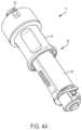
図4A~4Bを参照すれば、流体の閉鎖式移送のためのシステム10の1つの例は、注射器50を含む。注射器50のさまざまな態様は、参照において全体的に本明細書に組み込まれている、特許文献3に説明される。いくつかの例では、注射器50は、管状本体52と、外側スリーブ54と、アダプタ56とを有する。注射器50は、第1の医療容器と第2の医療容器との間、または医療容器と、バイアルアダプタなどの別の装置との間に流体連通を確立するように構成される。従来技術に知られているように、一般的に使用される医療流体容器は、シリンジ、バイアル、カートリッジ、流体含有バッグ、医療用ライン、または薬物、溶剤、および希釈剤などの医療流体を保つための類似の構造体および導管を含む。注射器50は、容器間に流体連通を確立するように使用され、それにより、ユーザは、流体を1つの容器から他のものに注入することができ、または流体を1つの容器から他のものに引き出すことができる。注射器50はまた、装置を第1および/または第2の医療容器にロックし、コネクタと容器との間の連結を維持するための構造体を含む。医療容器間の流体連通は、外側スリーブ54を、管状本体52の一部分が外側スリーブ54から延びる第1の位置から、外側スリーブ54が管状本体52を囲む第2の係合された位置まで移動させることによって確立される。管状本体52は、その近位端部から遠位端部まで管状本体52を通って長手方向に延びる針58(図4Bに示す)をさらに含む。針58は、管状本体52を通る流体経路を提供する管腔を画定する。針58は、医療級金属、または膜34などのシール作用配置を穿孔することができる先端部59になるように鋭利にすることができる他の材料から形成される。針58は、これが管状本体52内に全体的に封入される第1の位置と、針58が膜34を通るように強制され、第2の医療容器またはバイアルアダプタと接触させられる第2の露出された位置とを有する。 4A-4B, one example of a
図4Bを参照すると、膜34は、管状本体52の内部空洞を横切って延び、管状本体52内で移動しないように軸方向に保持される。膜34は、管状本体52の膜シート20内に保持される。膜34は、膜34の近位部分の少なくとも一部分と係合するへり部22によって膜シート20内に保持される。 Referring to FIG. 4B,
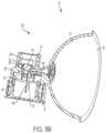
図5A~5Bを参照すれば、流体の閉鎖式移送のためのシステム10の1つの例は、プロテクタ60を含む。プロテクタ60のさまざまな態様は、参照において全体的に本明細書に組み込まれている、特許文献4に説明される。いくつかの例では、プロテクタ60は、第1の側部64および第2の側部66を有する本体62と、本体62の第2の側部66から延びる穿孔部材68(図5Bに示す)と、穿孔部材68を取り囲む取り外し可能なスリーブ70とを含む。プロテクタ60は、バイアル、ボトル、またはバッグなどのシール部材を有する流体容器から流体を移送するように構成される。 5A-5B, one example of a
引き続き図5A~5Bを参照すると、本体62は、本体62の第1の側部64から延びる第1の連結部分72を含む。第1の連結部分72は、プロテクタ60をシリンジアダプタまたは他の適切な装置または容器に取り付けるように構成されて、流体の除去または流体容器への流体の挿入を可能にする。プロテクタ60は、拡張可能なチャンバ76の使用によって流体移送中に容器内の圧力を均圧化するように構成された均圧化配置74をさらに含む。穿孔部材68は、長手方向通気チャネル78と、穿孔部材68の遠位端部から穿孔部材68の近位端部に向かって延びる通気開口部80とを画定する。通気開口部80は、長手方向通気チャネル78と流体連通している。長手方向通気チャネル78は、プロテクタ60の本体62を通って延び、均圧化配置74の拡張可能なチャンバ76と流体連通している。特に、プロテクタ60の使用中、長手方向通気チャネル78および均圧化配置74は、流体容器内の圧力を調節するために使用され、薬剤およびそのすべての蒸気をプロテクタ60および流体容器内に含む。均圧化配置74は、参照によって全体的に本明細書に組み込まれている、特許文献5に示されるバルーンまたは膜配置であってよいが、それだけに限定されるものではなく、フィルタ型の通気出口などの他の適切な均圧化配置が利用されてよい。 With continued reference to FIGS. 5A-5B,
図5Bを参照すると、プロテクタ60は、本体62を通って延び、第1の連結部分72と流体連通する長手方向流体チャネル82をさらに含む。第1の連結部分72は、長手方向流体チャネル82などの第1の連結部分72の内部をシールするように位置決めされたシール配置を含むことができる。シール配置は、図1A~1Bを参照して本明細書において説明する膜34などの膜34を含む。膜34は、第1の連結部分72の内部空洞を横切って延び、管状本体52内で移動しないように軸方向に保持される。膜34は、管状本体52の膜シート20内に保持される。膜34は、膜34の近位部分102の少なくとも一部分と係合するへり部22によって膜シート20内に保持される。いくつかの例では、へり部22は、膜34が膜シート20の遠位端部と係合した後、径方向に内方向に膜34上で折り畳まれる。いくつかの例では、へり部22は、膜34が膜シート20の遠位端部と係合した後、(図5Cに示す)第1の位置から(図5Bに示す)第2の位置に径方向に内方向に膜34上で折り畳まれる。このようにして、膜34は、軸方向に保持され得る。加えて、膜34の外周の少なくとも一部分は、膜シート20の内周の少なくとも一部分に結合されて、膜34を径方向に結合することができる。たとえば、膜34は、膜シート20に超音波式に溶接され得る。 Referring to FIG. 5B,
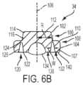
図6A~6Bを参照すれば、1つの例による膜34が、示される。膜34は、近位部分102および遠位部分104を有する本体100を含む。近位部分102および遠位部分104は、一緒になって一枚板状に形成されて本体100を単一の一体的構造体として画定する。いくつかの例では、近位部分102および遠位部分104は、別個に形成され、その後分離可能または分離不能な形で一緒に接合され得る。本体100は、近位部分102および遠位部分104の中央部分を通って延びる中央軸106の周りで実質的に線対称のものである。いくつかの例では、近位部分102および遠位部分104は、中央軸106を横切って実質的に円形断面を有することができる。さまざまな例では、膜34は、熱可塑性エラストマー材料、またはイソプレンなどのエラストマー材料から製造され得る。 6A-6B, one
引き続き図6A~6Bを参照すると、本体100は、近位部分102と遠位部分104との間にへり部108が形成されるように遠位部分104から径方向に外方向に延びるスカート107を有することができる。いくつかの例では、へり部108は、遠位部分104の近位表面110によって画定され得る。へり部108は、膜34の本体100が膜シート20の少なくとも一部分などのシステム10の少なくとも一部分と係合できるように係合表面を画定する。いくつかの例では、へり部108は、中央軸106に対して実質的に垂直になり得る。他の例では、へり部108は、中央軸106に対して非直交角度で傾斜され得る。へり部108は、平面状表面、非平面状表面、またはその組み合わせを有することができる。 With continued reference to FIGS. 6A-6B,
近位部分102の近位表面112は、中央軸106に位置合わせされた頂点を備えたドーム形状または凸形状表面を有することができる。他の例では、近位部分102の近位表面112は、実質的に平面状表面または円錐台表面を有することができる。別の例では、近位部分102の近位表面112は、1つまたは複数の線形および/または非線形セクションからなる非平面状表面を有することができる。近位部分102の近位表面112の外周は、近位部分102の側壁116に移行する放射状縁114を有することができる。側壁116は、遠位部分104の近位表面110に接合される。近位部分102および遠位部分104は、その両方の部分の中心を通って中央軸106が延びるように同軸に位置合わせされ得る。いくつかの例では、近位部分102の中央軸は、遠位部分104の中央軸に対してずらされ得る。 The
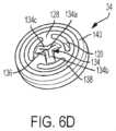
図6B~6Dを参照すると、遠位部分104は、遠位部分104の遠位表面140から近位方向に窪められた少なくとも1つのウエル120を有することができる。図6Bを参照すれば、少なくとも1つのウエル120は、遠位部分104の本体内に窪められたチャネルとして形成され得る。少なくとも1つのウエル120は、側壁126の対によって第2の端部124から分離された第1の端部122を有する。いくつかの例では、第1の端部122は開いており、一方で第2の端部124は閉じられている。側壁126は、少なくとも1つのウエル120の幅を画定する距離Wによって互いから離間されている。 6B-6D, the
いくつかの例では、少なくとも1つのウエル120は、中央軸106から半径Rを離して中央軸106の周りで円周方向に連続して、環状形状を画定することができる。他の例では、少なくとも1つのウエル120は、楕円形状、矩形形状、または他の多角形形状などの連続的な非円形の形状を有することができる。複数の連続ウエル120が、中央軸106から異なる半径を離して設けられ得る。他の例では、少なくとも1つのウエル120は、中央軸106から半径Rを離して中央軸106の周りの全周の一部分にわたって延びることができる。このようにして、ウエル120の末端部は、遠位部分104の本体によって互いから分離されて、断続的な環状形状を画定する。他の例では、少なくとも1つのウエル120は、断続的な楕円形状、矩形形状、または他の多角形形状などの断続的な非円形形状を有することができる。 In some examples, at least one well 120 can be circumferentially continuous around
別の例では、複数のウエル120が設けられ得る。ウエル120のすべては、中央軸106から同じ半径Rを離して設けられ得る。いくつかの例では、複数のウエル120の少なくとも1つは、残りのウエル120の半径Rより大きいか、または小さい半径に設けられ得る。図6C~6Dを参照すると、複数のウエル120の各々は、中央軸106周りの全周の角度延長部α上を延びてウエル120の長さを画定することができる。ウエル120は、均等または不均等の角度延長部αを有することができる。複数のウエル120の各々は、連結リブ128によって隣接するウエル120から分離され得る。各連結リブ128は、隣接するウエル120間の均等または不均等の角度範囲を有することができる。他の例では、少なくとも1つのウエル120は、隣接するウエル120との間に不均等の角度延長部βを有することができる。連結リブ128は、1つまたは複数のウエル120の存在による本体100の中央部分130と本体100の外側部分132との間の空隙を渡す。このようにして、図4Bに示す針58などのカニューレが膜34から後退された後、膜本体100の寸法的安定性が保持される。 In another example,
さまざまな例では、少なくとも1のウエル120は、システム10の少なくとも1つの構成要素と膜34との超音波溶接中などの特定の状況において膜34の圧縮を低減するように構成される。いかなる理論にも拘束されることを意図するものではないが、ハウジング16と膜34との超音波溶接の結果、膜本体100内に、針58が膜34を容易に貫通できる状態に影響を及ぼす膜材料の局所的圧縮が生じ得ることが実験によって判明している。少なくとも1つのウエル120は、本体100の中央部分130を、中央部分130を径方向に取り囲む外側部分132から、これらの間に空間を作りだすことによって隔てる。このようにして、膜34の外周の溶接によって起こり得る任意の材料圧縮は、中央部分130に影響を及ぼすことなく外側部分132に局所化されることになる。したがって、針58は、膜34の本体100を自由に貫通することができる。加えて、少なくとも1つのウエル120は、針58の貫通中、外側部分132の対応する拡張無しに中央部分130の径方向拡張を可能にする。このようにして、少なくとも1つのウエル120は、膜34の中央部分130の変形を吸収して、針58の貫通中のコアリングを最小限に抑えるか、または解消する。 In various examples, at least one well 120 is configured to reduce compression of
図6C~6Dを参照すると、膜34は、本体100の少なくとも一部分を通って延びる少なくとも1つのスリット134を有する。いくつかの例では、少なくとも1つのスリット134は、本体100の遠位部分104の少なくとも一部分を通って、(図6A~6Bに示す)中央軸106に沿う方向に延びる。他の例では、少なくとも1つのスリット134は、本体100の遠位部分104全体および近位部分102の少なくとも一部分を通って、中央軸106に沿う方向に延びる。さらなる例では、少なくとも1つのスリット134は、膜34の本体100全体を通って、中央軸106に沿う方向に延びる。中央軸106に沿う方向の少なくとも1つのスリット134の軸方向範囲は、膜34の本体100を通って針58の遠位端部30が貫通しなければならない長さを低減し、それによってコアリング(膜34の本体100からの材料の除去)の可能性を低減するか、または解消する。 6C-6D,
少なくとも1つのスリット134は、望ましくは、膜34を通る針58の挿入中にスリット134を針58が貫通するように配向される。たとえば、針58は、これが膜34の本体100を開位置になるように撓ませることによって膜34を通って挿入されるとき、少なくとも1つのスリット134を分割することができる。膜34からの針58の引き出し後、少なくとも1つのスリット134は、膜34の本体100のいかなる変形も生じさせずに閉じてその元の位置に戻るように構成される。このようにして、少なくとも1つのスリット134は、油圧シールを作りだして、膜34を通る液体またはガスの通過を防止する。図6Bに示すようないくつかの例では、少なくとも1つのスリット134は、実質的に線形、湾曲状、またはその組み合わせであってよく、それによってスリット134は、スリット134の場所において中央部分130を半分に二等分する。スリット134は、中央軸106に沿って膜34の断面平面において見たとき、丸みのある形状を有することができる。いくつかの例では、スリット134は、遠位部分104の遠位表面140から遠位に突起する隆起領域142上に位置決めされ得る。隆起領域142は、中央軸106と交差する頂点を備えた弓状形状を有することができる。隆起領域142の形状は、望ましくは、スリット134の形状に対応する。たとえば、線形に成形されたスリット134の場合、隆起領域142もまた、その長手方向の長さに沿って、中央軸106の平面に対して平行な平面において弓状断面プロファイルを備えて線形になり得る。 At least one
図6Cを参照すると、少なくとも1つのスリット134は、実質的に、スリット134a、134bの対がそのほぼ中点において交差する断面形状にされ得る。スリット134a、134bの対は、互いに対して実質的に直角で配向されてよく、またはスリット134a、134bの対は、鋭角または鈍角で交差することもできる。各スリット134a、134bは、本体100の遠位部分104の少なくとも一部分を通って、中央軸106に沿う方向に延びることができる。各スリット134a、134bは、実質的に、線形、湾曲状、またはその組み合わせであってよい。スリット134a、134bは、望ましくは、膜34を通る針58の挿入中にスリット134a、134bの対の交差点136を通って針58が貫通するように配向される。 Referring to FIG. 6C, the at least one
図6Dを参照すると、少なくとも1つのスリット134は、実質的にY字形状にされてよく、このとき3つの個々のスリット134a、134b、134cは、その端点の1つにおいて互いに連結されている。スリット134a、134b、134cは、これらの間の均等または不均等の角度でスリット134a、134b、134cが交差するように配向され得る。各スリット134a、134b、134cは、本体100の遠位部分104の少なくとも一部分を通って、中央軸106に沿う方向に延びることができる。各スリット134a、134b、134cは、実質的に、線形、湾曲状、またはその組み合わせであってよい。スリット134a、134b、134cは、望ましくは、膜34を通る針58の挿入中にスリット134a、134b、134cの交差点136を通って針58が貫通するように配向される。 Referring to FIG. 6D, at least one
引き続き図6Dを参照すると、膜34は、遠位部分104の遠位表面140から遠位に突起する保持リング138を有することができる。保持リング138は、膜34をその適所にハウジング16内に維持するように構成される。保持リング138は、ハウジング16上の対応する溝(図示せず)と係合するように成形される。たとえば、保持リング138は、中央軸106の方向に延びる平面に沿って得られた断面において実質的に半円の形状を有することができる。 With continued reference to FIG. 6D,
引き続き図6Dを参照すると、保持リング138は、中央軸106周りに中心を揃えた連続リングとして形成され得る。いくつかの例では、保持リング138は、不連続になることができ、それにより、これは、中央軸106の周りを完全には延びない。さらなる例では、保持リング138は、区画化されてよく、それにより、保持リング138は、2つまたはそれ以上の連結解除(分断)された区画から構成される。 With continued reference to FIG. 6D, retaining
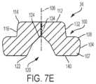
図7A~7Eを参照すると、さまざまな例による膜34が、示される。図7A~7Eに示す膜34の構成要素は、図6A~6Dを参照して本明細書に説明する膜34の構成要素に実質的に類似する。図7A~7Eの参照番号は、図6A~6Dの対応する参照番号の同一の構成要素を示すために使用される。図6A~6Dに全体的に示す膜34に関する前述の論議は、図7A~7Eに示す本開示の態様に適用可能であり、図6A~6Dに全体的に示す膜34と、図7A~7Eに全体的に示す膜34との間の唯一の相対的な違いが、これ以後論じられる。 7A-7E,
図7A~7Eに示す例の膜34は、一緒になって一枚板状に形成され、中央軸106の周りで線対称である近位部分102および遠位部分104を備えた本体100を有する。各例では、遠位部分104は、近位部分102と遠位部分104との間にへり部108が実質的に平面状の表面として形成されるようにスカート107を有する。近位部分102の近位表面112は、近位部分102の側壁116に移行する放射状縁114を備えた実質的に平面状の表面を有する。遠位部分104の遠位表面140は、実質的に平面状(図7B~7D)であるか、または湾曲状(図7A)である。各例では、膜34は、膜34の本体100を通って、中央軸106に沿う方向に延びる少なくとも1つのスリット134を有する。 The
図7A~7Dに示す各例では、遠位部分104は、遠位部分104の遠位表面140から近位方向に窪められたウエル120を有する。ウエル120は、側壁126の対によって第2の端部124から分離された第1の端部122を有する。図7A~7Bを参照すると、第2の端部124は丸みを帯びており、一方で側壁126は、側壁126間の幅Wが、第1の端部122から第2の端部124に向かう方向に変化する(すなわち増大するか、または低減する)ように湾曲される。 In each example shown in FIGS. 7A-7D,
図7C~7Dを参照すると、ウエル120の第2の端部124は、第2の端部124が中央軸106に向かって遠位から近位方向に先細になるように傾斜される。側壁126の対は、第1の側壁126aと第2の側壁126bとを有し、第1の側壁126aは中央軸106の方向に実質的に平行な方向に延び、第2の側壁126bは、中央軸106から離れて遠位から近位方向に先細になるように第1の側壁126aに対して角度を付けて延びる。遠位部分104の中央部分130は、外側部分132と同一平面上にあることができるか(図7C)、または外側部分132に対して近位方向に窪ませることができる(図7D)。図7Eを参照すると、ウエル120は、実質的にV字形状にされ、このとき第2の端部124は、膜34の中央部分に位置決めされ、中央軸106に位置合わせされる。側壁126は、複数の線形区画を有する。 7C-7D,
図8A~8Dを参照すると、追加の例による膜34が示される。各例では、膜34の遠位部分104は、遠位部分104の遠位表面140から近位方向に窪められた少なくとも1つのウエル120を有することができる。たとえば、少なくとも1つのウエル120は、遠位部分104の本体内に窪められるチャネルとして形成され得る。 8A-8D,
図8Dに示すようないくつかの例では、少なくとも1つのウエル120は、中央軸106から半径Rを離して中央軸106(図6Bに示す)の周りで円周方向に連続して環状形状を画定することができる。図8A~8Cに示すような他の例では、少なくとも1つのウエル120は、中央軸106から半径Rを離して中央軸106の周りの全周の一部分上を延びることができる。このようにして、ウエル120の末端部は、遠位部分104の本体によって互いから分離されて断続的な環状形状を画定する。図8A~8Cに示す例では、ウエル120のすべては、中央軸106から同じ半径Rを離して設けられる。図8A~8Cを参照すると、複数のウエル120の各々は、中央軸106の周りの全周の角度延長部α上を延びてウエル120の長さを画定することができる。ウエル120は、均等または不均等の角度延長部αを有することができる。複数のウエル120の各々は、連結リブ128によって隣接するウエル120から分離され得る。連結リブ128は、1つまたは複数のウエル120の存在による本体100の中央部分130と本体100の外側部分132との間の空隙を渡す。このようにして、図4Bに示す針58などのカニューレが膜34から後退された後、膜本体100の寸法的安定性が保持される。 In some examples, such as shown in FIG. 8D, at least one well 120 has a circumferentially continuous annular shape about central axis 106 (shown in FIG. 6B) spaced apart from
本開示は、例示的な設計として説明されてきたが、本開示は、この開示の趣旨および範囲内でさらに改変されてよい。本出願は、したがって、その通常の原理を使用する本開示の任意の変形形態、使用、または適応を含むように意図される。さらに、本出願は、本開示からのそのような逸脱を、本開示が関係し、付属の特許請求の範囲の制限内に入る技術分野において、知られているかまたは慣習的な実践内にこれらが入るように含むように意図される。 While this disclosure has been described as an exemplary design, the present disclosure may be further modified within the spirit and scope of this disclosure. This application is therefore intended to cover any variations, uses, or adaptations of the disclosure using its general principles. Further, the present application reserves the right to avoid such departures from the present disclosure as being within known or customary practice in the art to which this disclosure pertains and which falls within the limits of the appended claims. Intended to contain to enter.
Claims (24)
Translated fromJapanese中央軸に沿って遠位部分の反対側に近位部分を有する本体と、
前記近位部分と前記遠位部分との間の移行部にへり部が形成されるように前記遠位部分から径方向に外方向に延びるスカートと、
前記遠位部分内に窪められ、前記遠位部分の遠位端部から近位方向に延びる少なくとも1つのウエルであって、そのウエルによって前記遠位部分内にチャネルを形成し、前記チャネルは、開放された第1の端部と、閉鎖された底部の端部と、前記第1の端部と前記第2の端部との間を延びる側壁の対とを有する、少なくとも1つのウエルと、
前記本体の少なくとも一部分を通って、前記中央軸に沿ってまたは平行に位置合わせされた平面の方向に延びる少なくとも1つのスリットと
を備え、
前記少なくとも1つのウエルは、前記中央軸周りで円周方向に不連続になる膜。A membrane for use in connection with a closed system transfer device, comprising:
a body having a proximal portion opposite a distal portion along a central axis;
a skirt extending radially outwardly from the distal portion such that a lip is formed at the transition between the proximal portion and the distal portion;
at least one well recessed in said distal portion and extending proximally from a distal end of said distal portion, said well forming a channel in said distal portion, said channel at least one well having an open first end, a closed bottom end and a pair of side walls extending between said first end and said second end; ,
at least one slit extending through at least a portion of said body in a direction of a plane aligned along or parallel to said central axis;
The membrane wherein said at least one well is circumferentially discontinuous about said central axis.
中央軸に沿って遠位部分の反対側に近位部分を有する本体と、
前記近位部分と前記遠位部分との間の移行部にへり部が形成されるように前記遠位部分から径方向に外方向に延びるスカートと、
前記遠位部分内に窪められ、前記遠位部分の遠位端部から近位方向に延びる少なくとも1つのウエルであって、そのウエルによって前記遠位部分内にチャネルを形成し、前記チャネルは、開放された第1の端部と、閉鎖された底部の端部と、前記第1の端部と前記第2の端部との間を延びる側壁の対とを有する、少なくとも1つのウエルと、
前記本体の少なくとも一部分を通って、前記中央軸に沿ってまたは平行に位置合わせされた平面の方向に延びる少なくとも1つのスリットと
を備え、
前記少なくとも1つのウエルは、前記中央軸から同じ半径を離して位置決めされ、少なくとも1つの連結リブによって互いから分離される、複数のウエルを備える膜。A membrane for use in connection with a closed system transfer device, comprising:
a body having a proximal portion opposite a distal portion along a central axis;
a skirt extending radially outwardly from the distal portion such that a lip is formed at the transition between the proximal portion and the distal portion;
at least one well recessed in said distal portion and extending proximally from a distal end of said distal portion, said well forming a channel in said distal portion, said channel at least one well having an open first end, a closed bottom end and a pair of side walls extending between said first end and said second end; ,
at least one slit extending through at least a portion of said body in a direction of a plane aligned along or parallel to said central axis;
A membrane comprising a plurality of wells, wherein said at least one well is positioned at the same radius from said central axis and separated from each other by at least one connecting rib.
Applications Claiming Priority (4)
| Application Number | Priority Date | Filing Date | Title |
|---|---|---|---|
| US201762445393P | 2017-01-12 | 2017-01-12 | |
| US62/445,393 | 2017-01-12 | ||
| PCT/US2018/013274WO2018132540A1 (en) | 2017-01-12 | 2018-01-11 | Closed system stress resistant membrane |
| JP2019538121AJP7066723B2 (en) | 2017-01-12 | 2018-01-11 | Closed system stress resistance film |
Related Parent Applications (1)
| Application Number | Title | Priority Date | Filing Date |
|---|---|---|---|
| JP2019538121ADivisionJP7066723B2 (en) | 2017-01-12 | 2018-01-11 | Closed system stress resistance film |
Publications (2)
| Publication Number | Publication Date |
|---|---|
| JP2022097585A JP2022097585A (en) | 2022-06-30 |
| JP7258202B2true JP7258202B2 (en) | 2023-04-14 |
Family
ID=61074596
Family Applications (2)
| Application Number | Title | Priority Date | Filing Date |
|---|---|---|---|
| JP2019538121AActiveJP7066723B2 (en) | 2017-01-12 | 2018-01-11 | Closed system stress resistance film |
| JP2022073280AActiveJP7258202B2 (en) | 2017-01-12 | 2022-04-27 | Closed system stress resistant membrane |
Family Applications Before (1)
| Application Number | Title | Priority Date | Filing Date |
|---|---|---|---|
| JP2019538121AActiveJP7066723B2 (en) | 2017-01-12 | 2018-01-11 | Closed system stress resistance film |
Country Status (10)
| Country | Link |
|---|---|
| US (2) | US12290491B2 (en) |
| EP (1) | EP3568117B1 (en) |
| JP (2) | JP7066723B2 (en) |
| CN (1) | CN110325165B (en) |
| AU (1) | AU2018207411B2 (en) |
| BR (1) | BR112019014384B1 (en) |
| CA (1) | CA3049913A1 (en) |
| ES (1) | ES2857819T3 (en) |
| IL (1) | IL267972B2 (en) |
| WO (1) | WO2018132540A1 (en) |
Families Citing this family (11)
| Publication number | Priority date | Publication date | Assignee | Title |
|---|---|---|---|---|
| US7547300B2 (en) | 2006-04-12 | 2009-06-16 | Icu Medical, Inc. | Vial adaptor for regulating pressure |
| CA3176437A1 (en) | 2011-08-18 | 2013-02-21 | Icu Medical, Inc. | Pressure-regulating vial adaptors |
| AU2013204180B2 (en) | 2012-03-22 | 2016-07-21 | Icu Medical, Inc. | Pressure-regulating vial adaptors |
| US9089475B2 (en) | 2013-01-23 | 2015-07-28 | Icu Medical, Inc. | Pressure-regulating vial adaptors |
| CA3179530A1 (en) | 2013-07-19 | 2015-01-22 | Icu Medical, Inc. | Pressure-regulating fluid transfer systems and methods |
| WO2015195844A1 (en) | 2014-06-20 | 2015-12-23 | Icu Medical, Inc. | Pressure-regulating vial adaptors |
| EP3397231B1 (en) | 2016-01-29 | 2022-03-02 | ICU Medical, Inc. | Pressure-regulating vial adaptors |
| CA3037577A1 (en) | 2016-09-30 | 2018-04-05 | Icu Medical, Inc. | Pressure-regulating vial access devices and methods |
| HUE069141T2 (en)* | 2017-08-22 | 2025-02-28 | Hoffmann La Roche | Self-sealing septum |
| EP4087530B1 (en)* | 2020-01-09 | 2024-11-06 | Becton, Dickinson and Company | Drug transfer device |
| CA3166759A1 (en)* | 2020-02-05 | 2021-08-12 | Alicia MALBIN | System and method for priming an intravenous line |
Citations (8)
| Publication number | Priority date | Publication date | Assignee | Title |
|---|---|---|---|---|
| JP2002516160A (en) | 1998-05-29 | 2002-06-04 | ローレンス・エイ・リン | Luer receiver and fluid transfer method |
| JP2003522318A (en) | 1998-03-06 | 2003-07-22 | リービー アブナー | Improved urine sample container and method of using the same |
| WO2005004973A1 (en) | 2003-07-09 | 2005-01-20 | Jms Co., Ltd. | Mixed injection port |
| WO2013179596A1 (en) | 2012-05-31 | 2013-12-05 | 学校法人近畿大学 | Exposure-preventing cap |
| WO2014046271A1 (en) | 2012-09-21 | 2014-03-27 | 二プロ株式会社 | Medical connector and method for manufacturing same |
| WO2014104027A1 (en) | 2012-12-28 | 2014-07-03 | 株式会社ジェイ・エム・エス | Vial shield |
| JP2014521453A (en) | 2011-08-04 | 2014-08-28 | ベー・ブラウン・メルズンゲン・アクチエンゲゼルシャフト | Needleless connector device having a collapsible elastic membrane and corresponding method |
| JP2016524475A (en) | 2013-03-15 | 2016-08-18 | ドクター ピー インスティチュート エルエルシー | Controlled non-separating filling instrument and method |
Family Cites Families (21)
| Publication number | Priority date | Publication date | Assignee | Title |
|---|---|---|---|---|
| US5242393A (en)* | 1992-06-18 | 1993-09-07 | Becton, Dickinson And Company | Valved blunt cannula injection site |
| US7033339B1 (en)* | 1998-05-29 | 2006-04-25 | Becton Dickinson And Company (Part Interest) | Self sealing luer receiving stopcock |
| DE19500460A1 (en)* | 1995-01-10 | 1996-07-11 | Pohl Gmbh & Co Kg | Arrangement on infusion bottles or the like |
| US5921264A (en)* | 1997-08-28 | 1999-07-13 | Paradis; Joseph R. | Swabbable needleless valve |
| US20110130740A1 (en)* | 1998-03-06 | 2011-06-02 | Abner Levy | Medication Bottle for Use with Oral Syringe |
| DE10223560B4 (en)* | 2002-05-27 | 2006-01-19 | Fresenius Kabi Deutschland Gmbh | Connector for medical fluid containing packaging and packaging for medical fluids |
| SE526165C2 (en)* | 2003-04-23 | 2005-07-19 | Hugo Nilsson | Self-closing liquid dispensing device |
| BRPI0813906B8 (en)* | 2007-06-12 | 2021-06-22 | Becton Dickinson Co | syringe set including reuse prevention mechanism |
| US8523838B2 (en)* | 2008-12-15 | 2013-09-03 | Carmel Pharma Ab | Connector device |
| FR2948861B1 (en)* | 2009-08-07 | 2013-08-30 | Chanel Parfums Beaute | COSMETIC PRODUCT DEVICE HAVING DISTRIBUTION ORIFICE |
| IT1403656B1 (en)* | 2011-01-28 | 2013-10-31 | Frattini Paolo Giuseppe Gobbi | HERMETIC CLOSURE CONNECTOR, PERFORTABLE WITHOUT NEEDLE AND AUTOMATICALLY CLOSABLE FOR TIGHTENING, FOR FLEXIBLE PIPES INTENDED FOR THE COLLECTION AND DISTRIBUTION OF LIQUID SOLUTIONS FOR PHARMACOLOGICAL AND / OR NUTRITIONAL USE. |
| US10406344B2 (en) | 2012-09-11 | 2019-09-10 | Becton Dickinson and Company Limited | Adapter cap for drug transfer assembly |
| US9724269B2 (en) | 2012-11-30 | 2017-08-08 | Becton Dickinson and Company Ltd. | Connector for fluid communication |
| EP3650059B1 (en) | 2012-11-30 | 2022-07-27 | Becton Dickinson and Company Limited | Infusion adapter for drug transfer assembly |
| JP6446438B2 (en) | 2013-09-23 | 2018-12-26 | ベクトン ディキンソン アンド カンパニー リミテッド | Puncture member for container access device |
| AU2015249915B2 (en) | 2014-04-21 | 2017-11-30 | Becton Dickinson and Company Limited | System for closed transfer of fluids |
| EP4091597A1 (en)* | 2014-04-21 | 2022-11-23 | Becton Dickinson and Company Limited | Syringe adapter with disconnection feedback mechanism |
| KR102225095B1 (en)* | 2015-01-21 | 2021-03-08 | 가부시키가이샤 오츠카 세이야쿠 고죠 | Method of manufacturing a pot, and method of manufacturing a liquid medicine bag |
| CN106232164B (en) | 2015-01-30 | 2021-08-24 | 贝克顿·迪金森公司 | Pen needle hub with patient contact surface |
| EP3275476B1 (en)* | 2015-03-23 | 2020-03-18 | JMS Co., Ltd. | Adapter |
| EP3349713B1 (en)* | 2015-09-15 | 2023-11-01 | Dr. Py Institute LLC | Septum that decontaminates by interaction with penetrating element |
- 2018
- 2018-01-11EPEP18702015.1Apatent/EP3568117B1/enactiveActive
- 2018-01-11USUS15/868,123patent/US12290491B2/enactiveActive
- 2018-01-11CNCN201880013258.1Apatent/CN110325165B/enactiveActive
- 2018-01-11ESES18702015Tpatent/ES2857819T3/enactiveActive
- 2018-01-11WOPCT/US2018/013274patent/WO2018132540A1/ennot_activeCeased
- 2018-01-11JPJP2019538121Apatent/JP7066723B2/enactiveActive
- 2018-01-11CACA3049913Apatent/CA3049913A1/enactivePending
- 2018-01-11ILIL267972Apatent/IL267972B2/enunknown
- 2018-01-11BRBR112019014384-0Apatent/BR112019014384B1/enactiveIP Right Grant
- 2018-01-11AUAU2018207411Apatent/AU2018207411B2/enactiveActive
- 2022
- 2022-04-27JPJP2022073280Apatent/JP7258202B2/enactiveActive
- 2025
- 2025-04-01USUS19/097,113patent/US20250228743A1/enactivePending
Patent Citations (8)
| Publication number | Priority date | Publication date | Assignee | Title |
|---|---|---|---|---|
| JP2003522318A (en) | 1998-03-06 | 2003-07-22 | リービー アブナー | Improved urine sample container and method of using the same |
| JP2002516160A (en) | 1998-05-29 | 2002-06-04 | ローレンス・エイ・リン | Luer receiver and fluid transfer method |
| WO2005004973A1 (en) | 2003-07-09 | 2005-01-20 | Jms Co., Ltd. | Mixed injection port |
| JP2014521453A (en) | 2011-08-04 | 2014-08-28 | ベー・ブラウン・メルズンゲン・アクチエンゲゼルシャフト | Needleless connector device having a collapsible elastic membrane and corresponding method |
| WO2013179596A1 (en) | 2012-05-31 | 2013-12-05 | 学校法人近畿大学 | Exposure-preventing cap |
| WO2014046271A1 (en) | 2012-09-21 | 2014-03-27 | 二プロ株式会社 | Medical connector and method for manufacturing same |
| WO2014104027A1 (en) | 2012-12-28 | 2014-07-03 | 株式会社ジェイ・エム・エス | Vial shield |
| JP2016524475A (en) | 2013-03-15 | 2016-08-18 | ドクター ピー インスティチュート エルエルシー | Controlled non-separating filling instrument and method |
Also Published As
| Publication number | Publication date |
|---|---|
| BR112019014384B1 (en) | 2023-04-11 |
| JP7066723B2 (en) | 2022-05-13 |
| CN110325165A (en) | 2019-10-11 |
| JP2022097585A (en) | 2022-06-30 |
| US12290491B2 (en) | 2025-05-06 |
| JP2020503971A (en) | 2020-02-06 |
| BR112019014384A2 (en) | 2020-02-11 |
| EP3568117B1 (en) | 2021-03-03 |
| ES2857819T3 (en) | 2021-09-29 |
| WO2018132540A1 (en) | 2018-07-19 |
| AU2018207411B2 (en) | 2023-04-13 |
| US20250228743A1 (en) | 2025-07-17 |
| IL267972A (en) | 2019-09-26 |
| IL267972B1 (en) | 2023-06-01 |
| IL267972B2 (en) | 2023-10-01 |
| CN110325165B (en) | 2022-05-17 |
| AU2018207411A1 (en) | 2019-08-01 |
| EP3568117A1 (en) | 2019-11-20 |
| CA3049913A1 (en) | 2018-07-19 |
| US20180193227A1 (en) | 2018-07-12 |
Similar Documents
| Publication | Publication Date | Title |
|---|---|---|
| JP7258202B2 (en) | Closed system stress resistant membrane | |
| US20240157047A1 (en) | Infusion Adapter | |
| US11826540B2 (en) | Flexible cap for conical connectors | |
| US12383466B2 (en) | Fluid transfer device and packaging therefor | |
| CN111867546B (en) | Connection arrangements for closed system transfer of fluids | |
| EP0930056A2 (en) | Universal connector | |
| BR112014008551B1 (en) | VALVE SET FOR USE WITH CONTAINER OF LIQUID AND MEDICINE BOTTLE AND LIQUID MEDICINE TRANSFER UNIT | |
| US20230248957A1 (en) | System comprising a cap for a medical fluid container and an attachment part, medical fluid container, and method for producing a fluid container | |
| CN111450346B (en) | Adapter Cap for Medication Transfer Assembly | |
| US20160074580A1 (en) | Attachment Device For Medical Fluid Container |
Legal Events
| Date | Code | Title | Description |
|---|---|---|---|
| A621 | Written request for application examination | Free format text:JAPANESE INTERMEDIATE CODE: A621 Effective date:20220510 | |
| TRDD | Decision of grant or rejection written | ||
| A01 | Written decision to grant a patent or to grant a registration (utility model) | Free format text:JAPANESE INTERMEDIATE CODE: A01 Effective date:20230307 | |
| A61 | First payment of annual fees (during grant procedure) | Free format text:JAPANESE INTERMEDIATE CODE: A61 Effective date:20230404 | |
| R150 | Certificate of patent or registration of utility model | Ref document number:7258202 Country of ref document:JP Free format text:JAPANESE INTERMEDIATE CODE: R150 |