JP7257942B2 - Surface inspection device, shape correction device, and surface inspection method and shape correction method - Google Patents
Surface inspection device, shape correction device, and surface inspection method and shape correction methodDownload PDFInfo
- Publication number
- JP7257942B2 JP7257942B2JP2019216161AJP2019216161AJP7257942B2JP 7257942 B2JP7257942 B2JP 7257942B2JP 2019216161 AJP2019216161 AJP 2019216161AJP 2019216161 AJP2019216161 AJP 2019216161AJP 7257942 B2JP7257942 B2JP 7257942B2
- Authority
- JP
- Japan
- Prior art keywords
- inspected
- surface inspection
- shape
- deformation
- predetermined
- Prior art date
- Legal status (The legal status is an assumption and is not a legal conclusion. Google has not performed a legal analysis and makes no representation as to the accuracy of the status listed.)
- Active
Links
- 238000007689inspectionMethods0.000titleclaimsdescription113
- 238000000034methodMethods0.000titleclaimsdescription69
- 238000012937correctionMethods0.000titleclaimsdescription32
- 238000005259measurementMethods0.000claimsdescription72
- 239000013598vectorSubstances0.000claimsdescription50
- 238000004441surface measurementMethods0.000claimsdescription41
- 238000004364calculation methodMethods0.000claimsdescription27
- 238000006073displacement reactionMethods0.000claimsdescription24
- 230000005856abnormalityEffects0.000claimsdescription20
- 230000008859changeEffects0.000claimsdescription17
- 238000010586diagramMethods0.000description20
- 238000003825pressingMethods0.000description13
- 241001422033ThestylusSpecies0.000description11
- 238000003860storageMethods0.000description11
- 230000008569processEffects0.000description9
- 238000005452bendingMethods0.000description7
- 238000012545processingMethods0.000description7
- 230000007246mechanismEffects0.000description6
- 238000004519manufacturing processMethods0.000description5
- 239000000523sampleSubstances0.000description5
- 102220611460DNA ligase 3_S17A_mutationHuman genes0.000description4
- 102220611470DNA ligase 3_S17D_mutationHuman genes0.000description4
- 230000002950deficientEffects0.000description4
- 238000004512die castingMethods0.000description4
- 230000000694effectsEffects0.000description4
- 238000011088calibration curveMethods0.000description3
- 102220053993rs28929485Human genes0.000description3
- 238000012360testing methodMethods0.000description3
- 230000007723transport mechanismEffects0.000description3
- 238000005266castingMethods0.000description2
- 238000013461designMethods0.000description2
- 238000005516engineering processMethods0.000description2
- 229910052751metalInorganic materials0.000description2
- 239000002184metalSubstances0.000description2
- 229910000838Al alloyInorganic materials0.000description1
- 230000002159abnormal effectEffects0.000description1
- 230000008901benefitEffects0.000description1
- 238000004590computer programMethods0.000description1
- 238000012790confirmationMethods0.000description1
- 238000009826distributionMethods0.000description1
- 238000001746injection mouldingMethods0.000description1
- 239000004973liquid crystal related substanceSubstances0.000description1
- 238000012423maintenanceMethods0.000description1
- 239000000463materialSubstances0.000description1
- 238000012986modificationMethods0.000description1
- 230000004048modificationEffects0.000description1
- 230000003287optical effectEffects0.000description1
- 230000000704physical effectEffects0.000description1
- 239000002994raw materialSubstances0.000description1
- 239000011347resinSubstances0.000description1
- 229920005989resinPolymers0.000description1
- 239000004065semiconductorSubstances0.000description1
- 230000007704transitionEffects0.000description1
Images


Classifications
- G—PHYSICS
- G01—MEASURING; TESTING
- G01B—MEASURING LENGTH, THICKNESS OR SIMILAR LINEAR DIMENSIONS; MEASURING ANGLES; MEASURING AREAS; MEASURING IRREGULARITIES OF SURFACES OR CONTOURS
- G01B5/00—Measuring arrangements characterised by the use of mechanical techniques
- G01B5/30—Measuring arrangements characterised by the use of mechanical techniques for measuring the deformation in a solid, e.g. mechanical strain gauge
- G—PHYSICS
- G01—MEASURING; TESTING
- G01B—MEASURING LENGTH, THICKNESS OR SIMILAR LINEAR DIMENSIONS; MEASURING ANGLES; MEASURING AREAS; MEASURING IRREGULARITIES OF SURFACES OR CONTOURS
- G01B11/00—Measuring arrangements characterised by the use of optical techniques
- G01B11/02—Measuring arrangements characterised by the use of optical techniques for measuring length, width or thickness
- G01B11/06—Measuring arrangements characterised by the use of optical techniques for measuring length, width or thickness for measuring thickness ; e.g. of sheet material
- G01B11/0608—Height gauges
- G—PHYSICS
- G01—MEASURING; TESTING
- G01B—MEASURING LENGTH, THICKNESS OR SIMILAR LINEAR DIMENSIONS; MEASURING ANGLES; MEASURING AREAS; MEASURING IRREGULARITIES OF SURFACES OR CONTOURS
- G01B11/00—Measuring arrangements characterised by the use of optical techniques
- G01B11/16—Measuring arrangements characterised by the use of optical techniques for measuring the deformation in a solid, e.g. optical strain gauge
- G—PHYSICS
- G01—MEASURING; TESTING
- G01B—MEASURING LENGTH, THICKNESS OR SIMILAR LINEAR DIMENSIONS; MEASURING ANGLES; MEASURING AREAS; MEASURING IRREGULARITIES OF SURFACES OR CONTOURS
- G01B11/00—Measuring arrangements characterised by the use of optical techniques
- G01B11/30—Measuring arrangements characterised by the use of optical techniques for measuring roughness or irregularity of surfaces
- G01B11/306—Measuring arrangements characterised by the use of optical techniques for measuring roughness or irregularity of surfaces for measuring evenness
- G—PHYSICS
- G01—MEASURING; TESTING
- G01B—MEASURING LENGTH, THICKNESS OR SIMILAR LINEAR DIMENSIONS; MEASURING ANGLES; MEASURING AREAS; MEASURING IRREGULARITIES OF SURFACES OR CONTOURS
- G01B11/00—Measuring arrangements characterised by the use of optical techniques
- G01B11/24—Measuring arrangements characterised by the use of optical techniques for measuring contours or curvatures
Landscapes
- Physics & Mathematics (AREA)
- General Physics & Mathematics (AREA)
- Length Measuring Devices With Unspecified Measuring Means (AREA)
- Length Measuring Devices By Optical Means (AREA)
Description
Translated fromJapanese本発明は、被検査体の表面を検査するための表面検査装置および形状矯正装置、並びに表面検査方法および形状矯正方法に関する。 The present invention relates to a surface inspection apparatus, a shape correction apparatus, a surface inspection method, and a shape correction method for inspecting the surface of an object to be inspected.
スタイラスを測定面に沿って滑らかに走査し、高精度かつ高速な形状測定を実現するための技術の一つとして、特許文献1には、測定面と平行な方向へ指定した距離だけスタイラスを測定面に対して移動させる平行移動と、プローブに対するスタイラスの位置の変位量と変位方向とを含むスタイラス変位ベクトルの測定面に法線方向の大きさが予め定められた押込み量の設定値になるように、プローブを現在のスタイラス位置と過去のスタイラス位置との差から算出される測定面の法線方向に移動させる直交移動とを含む、プローブの測定面に対する相対位置を繰り返す、ことが記載されている。 As one of the technologies for realizing high-precision and high-speed shape measurement by smoothly scanning the stylus along the measurement surface,
ダイカスト鋳造は、アルミニウム合金などの溶融金属を精密な金型に圧入して、薄肉で強度の高い鋳物を成形する鋳造方式である。 Die casting is a casting method in which molten metal such as an aluminum alloy is pressed into a precision mold to form a thin, high-strength casting.
このようなダイカスト鋳造などの射出成形法により製造された成形品には、製品自体の反りや曲がりなどが発生することがある。このため、成形品の製造プロセスにおいては、成形品の反りや曲がりに対して逆方向の押圧力をプレス装置で加えることで矯正することがある。 A molded article manufactured by injection molding such as die casting may be warped or bent in the product itself. Therefore, in the process of manufacturing a molded product, the warpage or bending of the molded product may be corrected by applying a pressing force in the opposite direction using a press device.
この矯正を高精度に実施するためには、矯正後の製品の表面形状を測定し、以降の矯正条件を適正に調整することや、矯正前の製品の形状を測定し、測定結果に基づいて矯正条件を決定・実行することが望まれる。 In order to carry out this straightening with high accuracy, it is necessary to measure the surface shape of the product after straightening and appropriately adjust the subsequent straightening conditions, measure the shape of the product before straightening, and use the results based on the measurement results. It is desirable to determine and implement corrective conditions.
表面形状を測定する技術の一環として、上述の特許文献1では、測定面にスタイラスを接触させながら走査し、順次座標とスタイラスの傾きを読み取ることにより測定面の形状を測定して、スタイラスを測定面と平行な方向へ指定した距離だけ移動させる平行移動と、プローブを測定面の法線方向に移動させる直交移動とを繰り返すことで、スタイラスを滑らかに操作し、高精度な形状測定を実現している。 As part of the technology for measuring the surface shape, in the above-mentioned
しかしながら、特許文献1に記載の形状測定装置は、スタイラスを接触させながら走査させるため、形状の測定に時間がかかる、という課題がある。 However, the shape measuring apparatus described in
ここで、成形品の反りや曲がりは、製造工程において製品の寸法を作り込む際に塑性変形が均一に行われずに、残留応力やひずみ分布が残存することで発生する。これは、製造設備の運転条件や、素材の物性条件の変化に起因するものである。 Here, the warpage and bending of the molded product occur due to residual stress and strain distribution remaining without uniform plastic deformation when the dimensions of the product are made in the manufacturing process. This is due to changes in operating conditions of manufacturing equipment and physical property conditions of raw materials.
このため、連続して製造される製品の反りや曲がりをオンラインで測定し、反りや曲がりが次第に大きくなってきたら、製造設備の運転条件を調整することが望ましい。ここで、特許文献1に記載の形状測定装置では、形状の測定に時間がかかるため、連続して製造される製品の反りや曲がりをオンラインで測定するのは困難である、あるいはネックボトルとなる、との課題がある。 Therefore, it is desirable to measure the warpage and bending of products that are continuously manufactured on-line, and adjust the operating conditions of the manufacturing equipment when the warpage and bending gradually increase. Here, with the shape measuring device described in
このような課題は、矯正前の表面形状を測定して矯正に反映する場合においても同様である。 Such a problem is the same when the surface shape before correction is measured and reflected in the correction.
本発明は、ダイカスト品等の成形品の形状を従来に比べて短時間で高精度に評価することができる表面検査装置および形状矯正装置、並びに表面検査方法および形状矯正方法を提供することを目的とする。 SUMMARY OF THE INVENTION It is an object of the present invention to provide a surface inspection apparatus, a shape correction apparatus, a surface inspection method, and a shape correction method that can evaluate the shape of a molded product such as a die cast product in a short time and with high accuracy compared to the conventional art. and
本発明は、上記課題を解決する手段を複数含んでいるが、その一例を挙げるならば、被検査体の表面に設定された所定点の位置をそれぞれ計測する点計測部と、前記被検査体の複数の前記所定点の位置を同時に計測することにより複数の前記所定点を含む所定面の形状を計測する面計測部と、前記点計測部で計測された前記所定点の位置、および前記面計測部で計測された前記所定面の法線方向に基づいて、前記被検査体の基準形状からの変形量を求める演算部と、を備えたことを特徴とする。
The present invention includes a plurality of means for solving the above problems. a surface measuring unit that measures the shape of apredetermined surface includingthe plurality ofpredetermined points by simultaneously measuring the positions of the plurality of predetermined points, the positions of the predetermined points measured by the point measuring unit, and the and a computing unit that obtains a deformation amount from a reference shape of the object to be inspected based on the normal direction of the predetermined surface measured by the surface measuring unit.
本発明によれば、成形品の形状を従来に比べて短時間で高精度に評価することができる。上記した以外の課題、構成および効果は、以下の実施例の説明により明らかにされる。 ADVANTAGE OF THE INVENTION According to this invention, the shape of a molded product can be evaluated with high precision in a short time compared with the past. Problems, configurations and effects other than those described above will be clarified by the following description of the embodiments.
以下に本発明の表面検査装置および形状矯正装置、並びに表面検査方法および形状矯正方法の実施例を、図面を用いて説明する。なお、本明細書で用いる図面において、同一のまたは対応する構成要素には同一の符号を付け、これらの構成要素については繰り返しの説明を省略する場合がある。 Embodiments of the surface inspection apparatus, the shape correction apparatus, the surface inspection method, and the shape correction method of the present invention will be described below with reference to the drawings. In the drawings used in this specification, the same or corresponding components are denoted by the same reference numerals, and repeated description of these components may be omitted.
また、以下の各実施例では、ダイカスト鋳造等により成形された鋳造品の表面を検査する装置と方法、および鋳造品の形状を矯正する装置と方法について説明するが、本発明における検査対象である成形品はダイカスト鋳造により作製した鋳造品に限られず、他の様々な手法により作製された鋳造品に対して適用することができる。また、材質も金属に限定されず、樹脂などにも適用することができる。 Further, in each of the following embodiments, an apparatus and method for inspecting the surface of a cast product formed by die casting or the like and an apparatus and method for correcting the shape of the cast product will be described. The molded product is not limited to a cast product produced by die casting, but can be applied to a cast product produced by various other methods. Also, the material is not limited to metal, and can be applied to resin or the like.
<実施例1>
本発明の表面検査装置および表面検査方法の実施例1について図1乃至図6を用いて説明する。<Example 1>
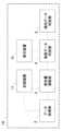
最初に、表面検査装置の全体構成について図1乃至図5を用いて説明する。図1は、本発明の実施例1による表面検査装置のシステム構成図である。図2は、点計測センサ201による被検査体101の所定点102の測定の模式図である。図3は、面計測センサ202による被検査体101の所定点102を含む所定面103の測定の模式図である。図4は、被検査体101の基準形状からの変形量を算出する方法を説明する図である。図5は、被検査体101の面計測データ306から被検査体101の所定点102における法線ベクトルを算出する方法の説明図である。 First, the overall configuration of the surface inspection apparatus will be described with reference to FIGS. 1 to 5. FIG. FIG. 1 is a system configuration diagram of a surface inspection apparatus according to
図1において、表面検査装置1は、被検査体101(図2参照)の表面を検査するための装置であり、データ取得部2、変形量演算部3、表面データ判定部4、記憶装置11、および表示装置10を備えている。 In FIG. 1, a
データ取得部2は、被検査体101の表面のうち所定点102における位置データ、および所定点102を含む所定面103の面計測データを取得し、取得したデータを変形量演算部3、記憶装置11に出力する。なお、所定点102は、1点とは限らず、複数の点を指す場合もある。 The
図2に示すように、データ取得部2は、点計測センサ201、面計測センサ202、ロボット203、検査ステージ204、および搬送機構205を備える。 As shown in FIG. 2 , the
点計測センサ201は、被検査体101の表面に設定された所定点102の位置をそれぞれ計測する測定機器であり、例えばレーザ変位計、白色干渉計などの光学測定器、あるいは接触式の形状測定器であるが、特には、測定精度の面で被検査体101に接触する接触式のセンサであることが望ましい。 The
この点計測センサ201は、図2に示すように、例えばロボット203の先端に設置されている。ロボット203を駆動して点計測センサ201を被検査体101に対して相対移動させて、点計測センサ201と被検査体の所定点102との距離を順次読み取ることにより、被検査体101の所定点102の位置データを得ることができる。 This
面計測センサ202は、被検査体101の複数点の位置を同時に計測することにより複数の所定点102を含む所定面103の形状を計測する測定機器であり、例えば3Dスキャナ、レーザ変位計、およびステレオカメラなどの光学測定機であるが、測定速度の面で被検査体101に接触せずに形状を計測する非接触式のセンサであることが望ましい。 The
この面計測センサ202も、図3に示すように、点計測センサ201と同様に、例えばロボット203の先端に設置される。好適には、面計測センサ202と点計測センサ201とはロボット203の先端に並列して配置されることが望ましい。ロボット203を駆動して面計測センサ202を被検査体101に対して相対的に移動させることにより、被検査体101の面計測データ306を得ることができる。 This
これら点計測センサ201による計測と面計測センサ202による計測とは、同時に行われることが望ましい。 It is desirable that the measurement by the
点計測センサ201における測定対象である所定点102は、反りなどの変形が発生する頻度が高い箇所が既知の被検査体101の場合は、そのような頻度が高い箇所に設定することができる。また、頻度の高い箇所から所定の距離の平面の点や、端部や角部から所定の距離の位置など、様々な条件に応じて適宜決定することができる。 If the
また、面計測センサ202における測定対象である所定面103の範囲は、所定面103に含まれる複数の点の位置のばらつきを表す指標がある閾値以下となるように決定されるのが望ましい。これにより、所定面103に含まれる複数の点の位置のばらつきを小さくして、所定面103に含まれる複数の点の位置から推定される所定面103の法線ベクトルの方向のばらつきが大きくなることを抑制することができる。 The range of the
また、所定面103の範囲を狭くしすぎないことで、所定面103に含まれる点の数をある程度確保して、個々の位置のばらつきを相殺し、精度を担保することができる。 Also, by not narrowing the range of the
したがって、所定面103の範囲は、所定面103に含まれる複数の点の位置のばらつきを表す指標がある閾値以下で、その範囲が最大となるように決定されるのが望ましい。 Therefore, the range of the
ロボット203は、点計測センサ201および面計測センサ202が様々な角度から被検査体101の形状を計測できるように、点計測センサ201および面計測センサ202の位置と角度が調整可能に構成されている。これにより、データ取得部2は、複数台の点計測センサ201および面計測センサ202を備える必要を防いでいる。 The
ロボット203は、例えば、被検査体101が平面状や直方体形状である場合は、被検査体101に対して平行移動可能な2軸移動の機構を用いることができる。また、被検査体101が複雑な形状の場合は、被検査体101を様々な方向からスキャンできるように3軸移動が可能な機構を用いることができる。 For example, when the
検査ステージ204は、被検査体101を載置するためのスペースである。被検査体101は、検査員の手によって、または被検査体101を把持するロボットや多関節アームなどを用いて、検査ステージ204に載置される。検査ステージ204は、点計測センサ201の位置と角度を固定したままで被検査体101の位置と角度を調整できる機構を備えていることができる。 The
検査ステージ204は、図2や図3には示していないが、被検査体101の位置と角度を固定するための機構や、被検査体101が位置と角度が正しく載置されていることを確認するためのセンサを備えてもよい。また、検査ステージ204は、被検査体101の大きさと形状に合わせて被検査体101を固定する部材を着脱可能に備えることもできる。検査ステージ204がこのような部材を着脱可能であることにより、データ取得部2は、複数品種の被検査体101に対して面計測データ306を得ることができる。 Although not shown in FIGS. 2 and 3, the
搬送機構205は、検査ステージ204に載置された被検査体101を、点計測センサ201あるいは面計測センサ202の測定範囲内に移動させる。また、測定が終了した後に、検査員が取りやすい位置まで、あるいは被検査体101を把持するロボットや多関節アームなどが被検査体101を取り出せる位置まで被検査体101を移動させる。 The
なお、面計測センサ202が、レーザ変位計などの、光切断法によって被検査体101の表面形状を取得する測定機である場合には、被検査体101に対して面計測センサ202を相対移動させて被検査体101の形状を計測するように構成することができる。このとき、ロボット203によって面計測センサ202を移動させる、あるいは検査ステージ204に設けた走査機構によって被検査体101を移動させることができる。 Note that if the
図1に戻り、変形量演算部3は、面計測センサ202で計測された面計測データから所定面103の法線方向を求める。そのうえで、点計測センサ201で計測された被検査体101の所定点102の位置データ、およびこの法線方向のデータを用いて被検査体101の基準形状からの変形量を求め、求めた変形量を表面データ判定部4に出力する。 Returning to FIG. 1 , the deformation
変形量演算部3で演算する変形量は、例えば被検査体101の表面形状と被検査体101の基準形状との差分の値の絶対値(大きさ)である。被検査体101の基準形状のデータは、例えば健全品データや設計データから得られた、被検査体の表面形状についての基準となるデータであり、記憶装置11に記憶されたものである。なお、変形量は、例えば被検査体101の基準位置からの距離、あるいは複数の基準位置からなる面との距離であってもよい。 The deformation amount calculated by the
より具体的には、変形量演算部3は、図4に示すように、被検査体101に基準形状301に対してz軸の負方向の曲がりがある場合において、所定点102における被検査体101の基準形状からの変形量を算出する。基準形状からの変形量は、被検査体101の所定点102における基準形状301からの変位ベクトル303の大きさと被検査体101の所定点102における法線ベクトル302とに基づいて算出する。 More specifically, as shown in FIG. 4 , the deformation
被検査体101の所定点102における基準形状301からの変位の変位ベクトル303は、点計測センサ201で取得した点計測センサ201と被検査体101の所定点102の距離と、あらかじめ取得しておいた点計測センサ201と基準形状301の距離との差分をとることにより、算出する。あるいは、あらかじめ点計測センサ201と被検査体101の他の所定点102の距離を取得しておき、その距離との差分をとることにより、算出してもよい。 The
被検査体101の所定点102における法線ベクトル302は、図5に示すように、面計測センサ202で取得した面計測データ306から、被検査体101の所定点102を含む所定面103を抽出し、算出する。 A
被検査体101の所定点102における法線ベクトル302を算出することにより、被検査体101の基準形状301からの変位ベクトル303は、法線ベクトル302方向に射影したベクトル304と、所定面103に射影したベクトル305と、に分解することができる。 By calculating the
この変位ベクトル303を法線ベクトル302方向に射影したベクトル304の大きさは、図4中のθを用いると、(変位ベクトル303の大きさ)×Cosθで求められる。この法線ベクトル302方向に射影したベクトル304は、被検査体101に対して垂直方向の変位ベクトルを表す。したがって、法線ベクトル302方向に射影したベクトル304は、被検査体101の変形にともなう対応点の位置ずれの影響も考慮した被検査体101の基準形状からの変形量を表すと言える。 The magnitude of a
また、変位ベクトル303を所定面103に射影したベクトル305の大きさは、図4中のθを用いると、(変位ベクトル303の大きさ)×Sinθで求められる。この所定面103に射影したベクトル305は、被検査体101に対して水平方向の変位ベクトルを表しており、変形のうち、被検査体101の反りに相当する成分といえる。 Also, the magnitude of a
ここで、変形量演算部3において、点計測センサ201で計測された所定点102の点計測データと面計測センサ202で計測された所定面103の面計測データとの位置合わせは、例えば、面計測センサ202で計測された所定面103の面計測データ306を健全品のデータや設計データに合わせてテンプレートを用いて変形することで所定点102の位置における面計測データ306を特定することにより行うことができるが、もちろんこの方法に限定されるものではない。 Here, in the deformation
表面データ判定部4は、変形量演算部3が求めた、被検査体101の基準形状からの変形量に基づいて、被検査体101が健全品であるか否か(すなわち、良品であるか不良品であるか)を判定することで被検査体101の形状の異常の有無を判定する。 The surface
これら変形量演算部3、表面データ判定部4は、コンピュータで構成される。このコンピュータは、各種データおよび処理結果等を用いた演算を行うためのCPU等の演算装置と、記憶装置11、表示装置10、入出力インターフェース(図示の都合上省略)等から構成されている。演算装置は、記憶装置11に記憶されたプログラムに従ってデータ処理を行う。また、このコンピュータは、表面データ判定部4の判定結果など、演算装置のデータ処理結果を表示装置10に表示することができる。 These deformation
なお、変形量演算部3、表面データ判定部4を構成するコンピュータで実行される動作の制御処理は、1つのプログラムにまとめられていても、それぞれが複数のプログラムに別れていてもよく、それらの組み合わせでもよい。また、プログラムの一部または全ては専用ハードウェアで実現してもよく、モジュール化されていても良い。 It should be noted that the control processing of the operations executed by the computer constituting the deformation
表示装置10は、表面データ判定部4の判定結果や、表面検査装置1が取得したデータや演算した結果を表示するための装置であり、液晶ディスプレイ等の表示機器である。なお、入力装置を兼ねたタッチパネル式の表示装置とすることができる。 The
記憶装置11は、表面データ判定部4の判定結果や、データ取得部2が取得したデータ、変形量演算部3が演算した結果を記憶するための装置であり、フラッシュメモリ等の半導体メモリやHDD等の磁気ディスク等の記録媒体である。この記憶装置11には、表面検査装置1の各機器の動作の制御用の各種パラメータや設定値、各種表示処理等を実行するための様々なコンピュータプログラム等についても記録されている。 The
次に、本実施例に係る表面検査方法について図6を参照して説明する。図6は、本実施例による表面検査方法の一連の手順を示すフローチャートである。 Next, a surface inspection method according to this embodiment will be described with reference to FIG. FIG. 6 is a flow chart showing a series of procedures of the surface inspection method according to this embodiment.
本実施例による表面検査方法は、図1に示した表面検査装置1により好適に実行される。また、本実施例による表面検査方法は、好適には、被検査体101がダイカスト鋳造品である場合には、矯正処理後に矯正プレスの効果の程度を確認するために実施することが望ましいが、矯正処理後に特に限定されるものではない。 The surface inspection method according to this embodiment is suitably executed by the
図6に示すように、まず、データ取得部2は、被検査体101の所定点102の位置データ、および被検査体101の所定点102を含む所定面の面計測データ306を取得する(ステップS11)。本ステップS11が、被検査体101の表面に設定された所定点102の位置をそれぞれ計測する点計測ステップ、および被検査体101の複数点の位置を同時に計測することにより複数の所定点102を含む所定面103の形状を面計測する面計測ステップに相当する。 As shown in FIG. 6, first, the
また、このステップS11における点計測ステップと面計測ステップとは、同時に行うことが望ましい。 Moreover, it is desirable that the point measurement step and the surface measurement step in step S11 are performed at the same time.
次いで、データ取得部2は、先のステップS11で取得した点計測データおよび面計測データを記憶装置11に記憶する(ステップS12)。 Next, the
次いで、変形量演算部3は、被検査体101の所定点102の位置データと被検査体101の基準形状の位置データとの差分を求める演算処理を行い、被検査体101の表面形状と基準形状との差分値を求める(ステップS13)。このステップS13が、点計測ステップで計測された所定点102の位置、および面計測ステップで計測された所定面103の法線方向に基づいて、被検査体101の基準形状からの変形量を求める演算ステップに相当する。 Next, the deformation
次いで、表面データ判定部4は、先のステップS13で求めた、被検査体101の基準形状からの変形量を基に、被検査体101の形状に異常があるか否かを判定する(ステップS14)。 Next, the surface
本ステップS14では、表面データ判定部4は、被検査体101の基準形状からの変形量が閾値より大きければ、その表面形状に異常があると判定し、変形量が閾値以下であれば、その表面形状に異常がないと判定する。この閾値は、予め任意に定めることができる。 In this step S14, the surface
その上で、表面データ判定部4は、被検査体101の全ての所定点102について形状の異常有無を判定し(ステップS15)、全ての所定点102に形状に異常がなければ、被検査体101が健全品であると判定して処理をステップS17に進める。 Then, the surface
次いで、表面データ判定部4は、被検査体101の形状に異常がなく、被検査体101は健全品であるという判定結果を表示装置10に出力する(ステップS17)。その後、処理をステップS18に進める。 Next, the surface
これに対し、被検査体101の全ての所定点102の形状の異常有無の判定(ステップS15)において、少なくとも1つの所定点102に形状の異常があれば、被検査体101が不良品であると判定し、処理をステップS16に進める。 On the other hand, if at least one
次いで、表面データ判定部4は、被検査体101の形状に異常があり、被検査体101は不良品であるという判定結果を表示装置10に出力する(ステップS16)。その後、処理をステップS18に進める。 Next, the surface
次いで、表面データ判定部4は、それぞれの判定結果を記憶装置11に記憶する(ステップS18)。記憶装置11は、表面検査装置1のその他の演算結果も記憶することができる。 Next, the surface
次に、本実施例の効果について説明する。 Next, the effects of this embodiment will be described.
上述した本発明の実施例1の表面検査装置1は、被検査体101の表面に設定された所定点102の位置をそれぞれ計測する点計測センサ201と、被検査体101の複数点の位置を同時に計測することにより複数の所定点102を含む所定面103の形状を計測する面計測センサ202と、点計測センサ201で計測された所定点102の位置、および面計測センサ202で計測された所定面103の法線方向に基づいて、被検査体101の基準形状からの変形量を求める変形量演算部3と、を備えている。 The
これによって、従来よりも少ない計測点数であるにもかかわらず、ダイカスト品等の成形品からなる被検査体101の基準形状301からの変形量を従来に比べて短時間で高精度に評価することできる。 As a result, the amount of deformation from the
また、変形量として、被検査体101の基準形状からの変位ベクトルを所定面103の法線方向に射影したベクトル304の大きさを求めるため、変形量の絶対量に相当する値を把握することができ、より正確な変形量を評価することができる。 As the amount of deformation, the magnitude of the
更に、変形量として、被検査体101の基準形状からの変位ベクトルを所定面103に射影したベクトル305の大きさを求めることで、被検査体101の反りの量に相当する値を把握することができるため、より高い精度で変形量を評価することができる。 Further, as the amount of deformation, the magnitude of the
また、点計測センサ201は、被検査体101に接触する接触式のセンサであり、面計測センサ202は、被検査体101に接触せずに形状を計測する非接触式のセンサであることにより、被検査体101の測定に要する時間を短く済ますことができるため、より速やかに変形量を求めることに寄与する。 Further, the
更に、点計測センサ201による計測と面計測センサ202による計測とが、同時に行われることによっても、被検査体101の測定に要する時間を短く済ますことができるため、より速やかに変形量を求めることに寄与する。 Furthermore, since the measurement by the
また、表面データ判定部4は、変形量に基づいて被検査体101の形状の異常の有無を判定することで、検査員の検査負担を軽減することができ、高精度な成形品の製造を従来に比べて容易に製造することができるようになる。 Further, the surface
<実施例2>
本発明の実施例2の表面検査装置および表面検査方法について図7乃至図9用いて説明する。図7は、本発明の実施例2による表面検査装置のシステム構成図である。図8は、製造個体数に対する被検査体101の基準形状301からの変形量の時系列変化を示す図である。図9は、本実施例による表面検査方法の一連の手順を示すフローチャートである。<Example 2>
A surface inspection apparatus and a surface inspection method according to a second embodiment of the present invention will be described with reference to FIGS. 7 to 9. FIG. FIG. 7 is a system configuration diagram of a surface inspection apparatus according to
図7に示すように、本実施例の表面検査装置1Aは、実施例1で説明した表面検査装置1に加えて傾向データ判定部5を備えており、変形量演算部3、表面データ判定部4に加えて、傾向データ判定部5が演算部を構成する。 As shown in FIG. 7, the
傾向データ判定部5は、被検査体101の基準形状からの変形量の時系列変化を分析することで変化傾向を分析し、変形量の変化傾向の異常有無を判定する。 The trend
図8には、基準形状301からの変形量の法線ベクトル302方向に射影したベクトル304、および/またはベクトル305の大きさをプロットしている。 FIG. 8 plots the magnitudes of a
より具体的には、傾向データ判定部5は、ベクトル304,305の大きさを連続的に監視し、ベクトル304,305の大きさが閾値を超えたタイミングを検知したら、異常ありという判定結果を表示装置10に出力する。これにより、被検査体に曲がりが次第に大きくなった時期を作業者に警告することができ、作業者はこの警告を受けて、設備状態の点検、または設備条件の更新を適切な時期に実施することができる。 More specifically, the trend
なお、傾向データ判定部5では、閾値には、例えば警報を発する閾値や、N.G.判定する閾値など複数の閾値を設けることができる。また、変形量の推移から、1以上の閾値に到達する時間を演算し、メンテナンス等の対処が必要となりそうなタイミングを表示装置10に出力して表示させることができる。 In addition, in the trend
次いで、本実施例における被検査体101の表面検査方法について図9を用いて説明する。本実施例による表面検査方法は、好適には、表面検査装置1Aにより実行される。 Next, a method for inspecting the surface of the
図9に示したフローチャートの各ステップは、基本的には図6に示した実施例1の各ステップと同じであるが、本フローチャートが図6に示した実施例1のフローチャートと異なるのは、被検査体101の基準形状301からの変形量の変化傾向の異常有無を判定するステップS17Aを備える点である。 Each step of the flowchart shown in FIG. 9 is basically the same as each step of the first embodiment shown in FIG. 6, but this flowchart differs from the flowchart of the first embodiment shown in FIG. The difference is that step S17A is provided to determine whether there is an abnormality in the change tendency of the amount of deformation of the
ステップS17の後、傾向データ判定部5は、被検査体101の基準形状からの変形量の時系列変化を分析して変化傾向を分析し、変形量の変化傾向の異常有無を判定する(ステップS17A)。このステップS17Aが、傾向判定ステップに相当する。異常判定の基準などは、上述のような閾値を用いた判定などとすることができる。 After step S17, the trend
その他の構成・動作は前述した実施例1の表面検査装置および表面検査方法と略同じ構成・動作であり、詳細は省略する。 Other configurations and operations are substantially the same as those of the surface inspection apparatus and the surface inspection method of the first embodiment described above, and the details are omitted.
本発明の実施例2の表面検査装置および表面検査方法においても、前述した実施例1の表面検査装置および表面検査方法とほぼ同様な効果が得られる。 The surface inspection apparatus and surface inspection method according to the second embodiment of the present invention also provide substantially the same effects as the surface inspection apparatus and surface inspection method according to the first embodiment.
また、表面検査装置1Aが、更に傾向データ判定部5を備え、変形量の時系列変化を分析することで変化傾向を分析し、変形量の変化傾向の異常有無を判定することにより、被検査体101の基準形状からの変形量の変化傾向の異常有無を自動的に求めることができる。これにより、作業者は、迅速に変形量を把握できることに加えて、被検査体101の曲がりが次第に大きくなる予兆を迅速に把握することができる。このため、従来に比べて適切な処置を速やかに取ることができるようになる。 In addition, the
<実施例3>
本発明の実施例3の形状矯正装置および形状矯正方法について図10乃至図13を用いて説明する。図10は、本発明の実施例3による表面検査装置のシステム構成図である。図11は、形状矯正部6の模式図である。図12は、表面検査装置での基準形状からの変形量からプレス装置の押込み量を算出するための校正曲線の一例を示す図である。図13は、本実施例による形状矯正方法の一連の手順を示すフローチャートである。<Example 3>
A shape correcting device and a shape correcting method according to Example 3 of the present invention will be described with reference to FIGS. 10 to 13. FIG. FIG. 10 is a system configuration diagram of a surface inspection apparatus according to
図10に示すように、本実施例の形状矯正装置7は、実施例2に示した表面検査装置1Aと、表面検査装置1Aで測定された変形量に基づいて被検査体101の変形を矯正する形状矯正部と、を備えている。 As shown in FIG. 10, the
形状矯正部6は、被検査体101の基準形状からの変形量に基づき、プレス装置の押込み量を算出し、求めた押込み量に基づいて被検査体101の矯正を実行する。 The
図11に示すように、形状矯正部6は、例えば、サーボモータ601によりシリンダー602を駆動させてプレス装置の可動型603を押込み、可動型603と固定型604の間に被検査体101を挟み押圧することで、被検査体101の形状を矯正する装置である。 As shown in FIG. 11, the
図12に示すように、被検査体101の反りや曲がりが小さくなるような基準形状301からの変形量と可動型603の押込み量の関係をあらかじめ校正曲線として取得しておき、この校正曲線を用いて、基準形状301からの変形量を可動型603の押込み量に換算することで、可動型603の押込み量を自動で適正な値に設定することができる。 As shown in FIG. 12, the relationship between the amount of deformation from the
本実施例においては、被検査体101の表面データの取得は形状矯正部6による形状矯正後の被検査体101に行われるため、形状矯正部6の条件が反映されるのは、表面データを取得した被検査体101以降に形状矯正が行われた被検査体101からとなる。 In this embodiment, the surface data of the object to be inspected 101 is obtained from the object to be inspected 101 whose shape has been corrected by the
なお、被検査体101の表面データの取得は、形状矯正前に行ってもよく、形状矯正の前後どちらとも行ってもよい。 The acquisition of the surface data of the
なお、図10では、形状矯正装置7が表面検査装置として実施例2の表面検査装置1Aを備えている場合について説明しているが、形状矯正装置7が備える表面検査装置は実施例2の表面検査装置1Aに限られず、実施例1の表面検査装置1とすることができる。この場合は、形状矯正部6は表面データ判定部4、あるいは変形量演算部3に接続されることが望ましい。 FIG. 10 illustrates a case where the
次いで、本実施例における被検査体101の形状矯正方法について図13を用いて説明する。本実施例による表面検査方法は、好適には、形状矯正装置7により実行される。 Next, a method for correcting the shape of the
図13に示したフローチャートの各ステップは、基本的には図9に示した実施例2の各ステップに加えて、ステップS17Aにおいて被検査体101の基準形状301からの変形量の変化傾向に異常があるか否か判定した後にそれぞれ判定に即したステップが実行されるとともに、実際に矯正を実行するステップが追加されている。 Each step of the flowchart shown in FIG. 13 is basically the steps of the second embodiment shown in FIG. After determining whether or not there is an error, a step corresponding to the determination is executed, and a step of actually performing correction is added.
本実施例では、ステップS17Aにおいて異常がないと判定(ステップS17B)された場合は処理をステップS17Dに進める。 In this embodiment, if it is determined in step S17A that there is no abnormality (step S17B), the process proceeds to step S17D.
これに対し、異常があると判定(ステップS17B)された場合は処理をステップS17Cに進め、ステップS13で演算された変形量に基づいて形状矯正部6の可動型603の押込み量を変更する(ステップS17C)。 On the other hand, if it is determined that there is an abnormality (step S17B), the process proceeds to step S17C, and the pushing amount of the
その後、形状矯正部6は、ステップS17Cで変更された可動型603の押込み量、あるいは元の可動型603の押込み量を用いて被検査体101の矯正を実行する(ステップS17D)。その後、処理をステップS18に進める。このステップS17Dが、表面検査ステップで測定された変形量に基づいて被検査体101の変形を矯正する形状矯正ステップに相当する。 After that, the
なお、実施例1の表面検査装置を備えている場合は、図6のステップS17の後にステップS17Dに直接移行して、測定された変形量に基づいて可動型603の押込み量を変更し、被検査体101の変形を矯正する矯正ステップを実行することが望ましい。 If the surface inspection apparatus of Example 1 is provided, the process proceeds directly to step S17D after step S17 in FIG. It is desirable to perform a correction step to correct deformation of the
表面検査装置や表面検査方法の他の構成・動作は前述した実施例1,2の表面検査装置や表面検査方法と略同じ構成・動作であり、詳細は省略する。 Other configurations and operations of the surface inspection apparatus and surface inspection method are substantially the same as those of the surface inspection apparatus and surface inspection method of the first and second embodiments described above, and the details thereof are omitted.
本発明の実施例3の形状矯正装置7は、前述した実施例1の表面検査装置1あるいは実施例2の表面検査装置1Aと、表面検査装置1,1Aで測定された変形量に基づいて被検査体101の変形を矯正する形状矯正部と、を備えているため、速やかにかつ高精度にその変形量を評価できる。このため、正確にかつ迅速に評価された変形量に基づき、可動型の押込み量を自動で適正な値に設定することができる。これにより、ダイカスト品等の成形品の形状を短時間で高精度に矯正することができる、との効果が得られる。 A
<その他>
なお、本発明は、上記の実施例に限定されるものではなく、様々な変形が可能である。例えば、上記の実施例は、本発明を分かりやすく説明するために詳細に説明したものであり、本発明は、必ずしも説明した全ての構成を備える態様に限定されるものではない。<Others>
It should be noted that the present invention is not limited to the above embodiments, and various modifications are possible. For example, the above embodiments have been described in detail in order to facilitate understanding of the present invention, and the present invention is not necessarily limited to aspects having all the described configurations.
また、ある実施例の構成の一部を他の実施例の構成に置き換えることが可能である。また、ある実施例の構成に他の実施例の構成を加えることも可能である。また、各実施例の構成の一部について、削除したり、他の構成を追加・置換したりすることが可能である。 Also, part of the configuration of one embodiment can be replaced with the configuration of another embodiment. It is also possible to add the configuration of another embodiment to the configuration of one embodiment. Moreover, it is possible to delete a part of the configuration of each embodiment, or to add or replace another configuration.
1,1A…表面検査装置
2…データ取得部
3…変形量演算部(演算部)
4…表面データ判定部(演算部)
5…傾向データ判定部(演算部)
6…形状矯正部
7…形状矯正装置
10…表示装置
11…記憶装置
101…被検査体
102…被検査体の所定点
103…被検査体の所定点を含む所定面
201…点計測センサ(点計測部)
202…面計測センサ(面計測部)
203…ロボット
204…検査ステージ
205…搬送機構
301…基準形状
302…被検査体の所定点における法線ベクトル
303…被検査体の所定点における変位ベクトル
304…被検査体の所定点における変位ベクトルを所定面の法線方向に射影したベクトル
305…被検査体の所定点における変位ベクトルを所定面に射影したベクトル
306…被検査体の面計測データ
601…サーボモータ
602…シリンダー
603…可動型
604…固定型DESCRIPTION OF
4 ... surface data determination unit (calculation unit)
5... Trend data determination unit (calculation unit)
6
202 ... Surface measurement sensor (surface measurement unit)
203
Claims (16)
Translated fromJapanese前記被検査体の複数の前記所定点の位置を同時に計測することにより複数の前記所定点を含む所定面の形状を計測する面計測部と、
前記点計測部で計測された前記所定点の位置、および前記面計測部で計測された前記所定面の法線方向に基づいて、前記被検査体の基準形状からの変形量を求める演算部と、を備えた
ことを特徴とする表面検査装置。a point measuring unit that measures the positions of predetermined points set on the surface of the object to be inspected;
a surface measuring unit that simultaneously measures the positions of the pluralityof predetermined points on the object to be inspected to measure the shape of a predetermined surface includingthe plurality ofpredetermined points;
a calculation unit that calculates a deformation amount from a reference shape of the object to be inspected based on the position of the predetermined point measured by the point measurement unit and the normal direction of the predetermined surface measured by the surface measurement unit; A surface inspection device comprising:
前記演算部は、前記変形量として、前記被検査体の基準形状からの変位ベクトルを前記所定面の法線方向に射影したベクトルの大きさを求める
ことを特徴とする表面検査装置。In the surface inspection device according to claim 1,
The surface inspection apparatus, wherein the calculation unit obtains, as the amount of deformation, a magnitude of a vector obtained by projecting a displacement vector from a reference shape of the object to be inspected in a normal direction of the predetermined surface.
前記演算部は、前記変形量として、前記被検査体の基準形状からの変位ベクトルを前記所定面に射影したベクトルの大きさを求める
ことを特徴とする表面検査装置。In the surface inspection device according to claim 1,
The surface inspection apparatus, wherein the calculation unit obtains, as the amount of deformation, a magnitude of a vector obtained by projecting a displacement vector from a reference shape of the object to be inspected onto the predetermined plane.
前記演算部は、前記変形量の時系列変化を分析することで変化傾向を分析し、前記変形量の変化傾向の異常有無を判定する
ことを特徴とする表面検査装置。In the surface inspection device according to claim 1,
The surface inspection device, wherein the calculating unit analyzes a change tendency by analyzing a time-series change of the deformation amount, and determines whether or not there is an abnormality in the change tendency of the deformation amount.
前記点計測部は、前記被検査体に接触する接触式のセンサであり、
前記面計測部は、前記被検査体に接触せずに形状を計測する非接触式のセンサである
ことを特徴とする表面検査装置。In the surface inspection device according to claim 1,
The point measuring unit is a contact sensor that contacts the object to be inspected,
A surface inspection apparatus, wherein the surface measurement unit is a non-contact sensor that measures the shape of the object without contacting the object.
前記点計測部による計測と前記面計測部による計測とが、同時に行われる
ことを特徴とする表面検査装置。In the surface inspection device according to claim 1,
A surface inspection apparatus, wherein the measurement by the point measurement unit and the measurement by the surface measurement unit are performed simultaneously.
前記演算部は、前記変形量に基づいて、前記被検査体の形状の異常の有無を判定する
ことを特徴とする表面検査装置。In the surface inspection device according to claim 1,
The surface inspection apparatus, wherein the calculation unit determines whether or not there is an abnormality in the shape of the object to be inspected based on the deformation amount.
前記表面検査装置で測定された前記変形量に基づいて前記被検査体の変形を矯正する形状矯正部と、を備えた
ことを特徴とする形状矯正装置。A surface inspection apparatus according to any one of claims 1 to 7;
and a shape correction unit that corrects deformation of the object to be inspected based on the amount of deformation measured by the surface inspection device.
前記被検査体の複数の前記所定点の位置を同時に計測することにより複数の前記所定点を含む所定面の形状を面計測する面計測ステップと、
前記点計測ステップで計測された前記所定点の位置、および前記面計測ステップで計測された前記所定面の法線方向に基づいて、前記被検査体の基準形状からの変形量を求める演算ステップと、を有する
ことを特徴とする表面検査方法。a point measurement step of measuring the positions of predetermined points set on the surface of the object to be inspected;
a surface measurement step of measuring a shape of a predetermined surface including the plurality ofpredetermined points by simultaneously measuring the positions ofthe plurality ofpredetermined points of the object to be inspected;
a calculation step of obtaining a deformation amount from a reference shape of the object to be inspected based on the position of the predetermined point measured in the point measurement step and the normal direction of the predetermined surface measured in the surface measurement step; A surface inspection method comprising:
前記変形量として、前記被検査体の基準形状からの変位ベクトルを前記所定面の法線方向に射影したベクトルの大きさを求める
ことを特徴とする表面検査方法。In the surface inspection method according to claim 9,
A surface inspection method, wherein a magnitude of a vector obtained by projecting a displacement vector from a reference shape of the object to be inspected in a normal direction of the predetermined surface is obtained as the amount of deformation.
前記変形量として、前記被検査体の基準形状からの変位ベクトルを前記所定面に射影したベクトルの大きさを求める
ことを特徴とする表面検査方法。In the surface inspection method according to claim 9,
A surface inspection method, wherein a magnitude of a vector obtained by projecting a displacement vector from a reference shape of the object to be inspected onto the predetermined plane is obtained as the amount of deformation.
前記被検査体の基準形状からの変形量の時系列変化を分析して変化傾向を分析し、前記変形量の変化傾向の異常有無を判定する傾向判定ステップを更に有する
ことを特徴とする表面検査方法。In the surface inspection method according to claim 9,
A surface inspection characterized by further comprising a trend determination step of analyzing a time-series change in the amount of deformation from the reference shape of the object to be inspected, analyzing a change trend, and determining whether or not there is an abnormality in the trend of change in the amount of deformation. Method.
前記点計測ステップでは、前記被検査体に接触して前記所定点の位置を計測し、
前記面計測ステップでは、前記被検査体に接触せずに形状を計測する
ことを特徴とする表面検査方法。In the surface inspection method according to claim 9,
In the point measurement step, the position of the predetermined point is measured by contacting the object to be inspected;
A surface inspection method, wherein, in the surface measurement step, the shape is measured without contacting the object to be inspected.
前記点計測ステップによる計測と前記面計測ステップによる計測とを、同時に行う
ことを特徴とする表面検査方法。In the surface inspection method according to claim 9,
A surface inspection method, wherein the measurement by the point measurement step and the measurement by the surface measurement step are performed simultaneously.
前記演算ステップでは、前記変形量に基づいて、前記被検査体の形状の異常の有無を判定する
ことを特徴とする表面検査方法。In the surface inspection method according to claim 9,
The surface inspection method, wherein, in the calculation step, presence/absence of an abnormality in the shape of the object to be inspected is determined based on the deformation amount.
前記表面検査方法で測定された前記変形量に基づいて前記被検査体の変形を矯正する形状矯正ステップと、を有する
ことを特徴とする形状矯正方法。Each step of the surface inspection method according to any one of claims 9 to 15;
and a shape correction step of correcting deformation of the object to be inspected based on the deformation amount measured by the surface inspectionmethod .
Priority Applications (4)
| Application Number | Priority Date | Filing Date | Title |
|---|---|---|---|
| JP2019216161AJP7257942B2 (en) | 2019-11-29 | 2019-11-29 | Surface inspection device, shape correction device, and surface inspection method and shape correction method |
| PCT/JP2020/043332WO2021106767A1 (en) | 2019-11-29 | 2020-11-20 | Surface inspection device, shape correction device, and surface inspection method, and shape correction method |
| US17/778,331US12215971B2 (en) | 2019-11-29 | 2020-11-20 | Shape correction device and shape correction method based on amount of deformation measured by point measurement sensor and surface measurement sensor |
| CN202080077780.3ACN114729800B (en) | 2019-11-29 | 2020-11-20 | Surface inspection device, shape correction device, surface inspection method, and shape correction method |
Applications Claiming Priority (1)
| Application Number | Priority Date | Filing Date | Title |
|---|---|---|---|
| JP2019216161AJP7257942B2 (en) | 2019-11-29 | 2019-11-29 | Surface inspection device, shape correction device, and surface inspection method and shape correction method |
Publications (3)
| Publication Number | Publication Date |
|---|---|
| JP2021085807A JP2021085807A (en) | 2021-06-03 |
| JP2021085807A5 JP2021085807A5 (en) | 2022-04-14 |
| JP7257942B2true JP7257942B2 (en) | 2023-04-14 |
Family
ID=76088751
Family Applications (1)
| Application Number | Title | Priority Date | Filing Date |
|---|---|---|---|
| JP2019216161AActiveJP7257942B2 (en) | 2019-11-29 | 2019-11-29 | Surface inspection device, shape correction device, and surface inspection method and shape correction method |
Country Status (4)
| Country | Link |
|---|---|
| US (1) | US12215971B2 (en) |
| JP (1) | JP7257942B2 (en) |
| CN (1) | CN114729800B (en) |
| WO (1) | WO2021106767A1 (en) |
Families Citing this family (1)
| Publication number | Priority date | Publication date | Assignee | Title |
|---|---|---|---|---|
| JP7618472B2 (en)* | 2020-03-31 | 2025-01-21 | 株式会社ユーシン精機 | Method and system for estimating normal vector of mold and attachment |
Citations (1)
| Publication number | Priority date | Publication date | Assignee | Title |
|---|---|---|---|---|
| JP2014126381A (en) | 2012-12-25 | 2014-07-07 | Nikon Corp | Shape measurement device, structure fabrication system, shape measurement method, structure fabrication method and shape measurement program |
Family Cites Families (40)
| Publication number | Priority date | Publication date | Assignee | Title |
|---|---|---|---|---|
| US5046852A (en)* | 1988-09-16 | 1991-09-10 | The Boeing Company | Method and apparatus for bending an elongate workpiece |
| US4995716A (en)* | 1989-03-09 | 1991-02-26 | Par Technology Corporation | Method and apparatus for obtaining the topography of an object |
| JPH04176543A (en)* | 1990-11-08 | 1992-06-24 | Fanuc Ltd | Control unit for digitizing |
| JPH0914931A (en)* | 1995-06-27 | 1997-01-17 | Matsushita Electric Works Ltd | Optical displacement measuring device |
| JP2000008946A (en)* | 1998-06-23 | 2000-01-11 | Toyota Motor Corp | Internal combustion engine piston |
| JP3344649B2 (en)* | 1998-08-19 | 2002-11-11 | 理化学研究所 | Evaluation method for shape error of free-form surface |
| EP1285224A1 (en)* | 2000-05-16 | 2003-02-26 | Steinbichler Optotechnik Gmbh | Method and device for determining the 3d profile of an object |
| US7251580B2 (en)* | 2003-10-20 | 2007-07-31 | Mitutoyo Corporation | Method for measuring curved surface of workpiece, program and medium thereof |
| WO2005119174A1 (en)* | 2004-05-26 | 2005-12-15 | Werth Messtechnik Gmbh | Coordinate measuring apparatus and method for measuring an object |
| JP4776197B2 (en)* | 2004-09-21 | 2011-09-21 | 日本特殊陶業株式会社 | Wiring board inspection equipment |
| JP4615951B2 (en)* | 2004-09-30 | 2011-01-19 | 株式会社日立製作所 | Shape model creation method and structure optimization system |
| DE102007021809A1 (en)* | 2007-04-20 | 2008-10-23 | Werth Messtechnik Gmbh | Method and device for dimensional measurement with coordinate measuring machines |
| ATE521872T1 (en)* | 2008-04-22 | 2011-09-15 | Leica Geosystems Ag | MEASURING METHOD FOR A LINK ARM COORDINATE MEASURING MACHINE |
| JP4968600B1 (en)* | 2011-01-13 | 2012-07-04 | 株式会社東京精密 | Roundness measuring device and method of correcting misalignment |
| CN104024793B (en)* | 2011-10-24 | 2017-02-15 | 株式会社日立制作所 | Shape inspection method and device |
| EP2647477B1 (en)* | 2012-04-05 | 2019-10-30 | FIDIA S.p.A. | Device for error correction for CNC machines |
| JP6124570B2 (en)* | 2012-11-30 | 2017-05-10 | 株式会社ミツトヨ | XYZ orthogonal measuring device |
| JP5747180B2 (en) | 2012-12-06 | 2015-07-08 | パナソニックIpマネジメント株式会社 | Shape measuring method and shape measuring apparatus |
| JP2014169947A (en)* | 2013-03-05 | 2014-09-18 | Hitachi Ltd | Shape inspection method and device thereof |
| JP5923054B2 (en)* | 2013-04-08 | 2016-05-24 | 株式会社神戸製鋼所 | Shape inspection device |
| US10393505B2 (en)* | 2013-12-06 | 2019-08-27 | Werth Messtechnik Gmbh | Device and method for measuring workpieces |
| JP2015141139A (en)* | 2014-01-29 | 2015-08-03 | 株式会社ミツトヨ | Manual measurement device |
| EP2916099B1 (en)* | 2014-03-07 | 2020-09-30 | Hexagon Technology Center GmbH | Articulated arm coordinate measuring machine |
| EP2930462B1 (en)* | 2014-04-08 | 2017-09-13 | Hexagon Technology Center GmbH | Method for generating information about a sensor chain of a coordinate measuring machine (CMM) |
| JP6316663B2 (en)* | 2014-05-30 | 2018-04-25 | 株式会社キーエンス | Coordinate measuring device |
| DE102015205738A1 (en)* | 2015-03-30 | 2016-10-06 | Carl Zeiss Industrielle Messtechnik Gmbh | Motion measuring system of a machine and method for operating the motion measuring system |
| EP3104118B1 (en)* | 2015-06-12 | 2019-02-27 | Hexagon Technology Center GmbH | Method to control a drive mechanism of an automated machine having a camera |
| WO2017033581A1 (en)* | 2015-08-27 | 2017-03-02 | 株式会社東京精密 | Surface shape measuring method, misalignment amount calculating method, and surface shape measuring device |
| DE102016100308A1 (en)* | 2016-01-11 | 2017-07-13 | Datron Ag | Method for determining a reference coordinate of a workpiece and a processing machine |
| EP3203179B1 (en)* | 2016-02-05 | 2019-04-03 | Hexagon Technology Center GmbH | Measuring machine based on a delta robot assembly |
| JP6691837B2 (en)* | 2016-06-27 | 2020-05-13 | 株式会社キーエンス | measuring device |
| WO2018052015A1 (en)* | 2016-09-14 | 2018-03-22 | 日本電気株式会社 | Analysis support device for system, analysis support method and program for system |
| JP2018072202A (en)* | 2016-10-31 | 2018-05-10 | 株式会社東京精密 | Shape measurement device and method for shape measurement |
| DE102016124549B4 (en)* | 2016-12-15 | 2019-11-07 | Carl Zeiss Industrielle Messtechnik Gmbh | measuring system |
| WO2019075165A1 (en)* | 2017-10-11 | 2019-04-18 | Board Of Regents, The University Of Texas System | Method and system for optically detecting and characterizing defects in semiconductors |
| JP2019113329A (en)* | 2017-12-21 | 2019-07-11 | 株式会社ニューフレアテクノロジー | Displacement measurement device and electron beam inspection device |
| JP7143567B2 (en)* | 2018-09-14 | 2022-09-29 | 株式会社島津テクノリサーチ | Material testing machine and radiation CT equipment |
| WO2020157973A1 (en)* | 2019-02-01 | 2020-08-06 | 日本電気株式会社 | Image processing device |
| US11150189B1 (en)* | 2019-09-03 | 2021-10-19 | Innolux Corporation | Methods of manufacturing a light source carrier and an electronic device, and a light source qualification method |
| DE102020111509B4 (en)* | 2020-04-28 | 2023-04-20 | Carl Zeiss Industrielle Messtechnik Gmbh | Coordinate measuring device and method for measuring coordinates of a workpiece |
- 2019
- 2019-11-29JPJP2019216161Apatent/JP7257942B2/enactiveActive
- 2020
- 2020-11-20CNCN202080077780.3Apatent/CN114729800B/enactiveActive
- 2020-11-20USUS17/778,331patent/US12215971B2/enactiveActive
- 2020-11-20WOPCT/JP2020/043332patent/WO2021106767A1/ennot_activeCeased
Patent Citations (1)
| Publication number | Priority date | Publication date | Assignee | Title |
|---|---|---|---|---|
| JP2014126381A (en) | 2012-12-25 | 2014-07-07 | Nikon Corp | Shape measurement device, structure fabrication system, shape measurement method, structure fabrication method and shape measurement program |
Also Published As
| Publication number | Publication date |
|---|---|
| CN114729800A (en) | 2022-07-08 |
| JP2021085807A (en) | 2021-06-03 |
| US20220390222A1 (en) | 2022-12-08 |
| WO2021106767A1 (en) | 2021-06-03 |
| US12215971B2 (en) | 2025-02-04 |
| CN114729800B (en) | 2024-01-09 |
Similar Documents
| Publication | Publication Date | Title |
|---|---|---|
| US9746303B2 (en) | Coordinate measuring machine and method for calculating correction matrix by coordinate measuring machine | |
| JP5823306B2 (en) | Calibration method of surface texture measuring machine | |
| US20120078418A1 (en) | Robot calibration apparatus and method for same | |
| US20240142355A1 (en) | Thickness correction for video extensometer systems and methods | |
| US6701267B2 (en) | Method for calibrating probe and computer-readable medium | |
| CN104976950A (en) | Object space information measuring device and method and image capturing path calculating method | |
| JP7257942B2 (en) | Surface inspection device, shape correction device, and surface inspection method and shape correction method | |
| JP6884077B2 (en) | Surface inspection equipment and surface inspection method | |
| US11433551B2 (en) | Measurement system and method for positioning accuracy of a robotic arm | |
| JP4531685B2 (en) | Shape measuring device and shape measuring method | |
| JP2000081329A (en) | Shape measuring method and device | |
| CN114459310B (en) | Repeated positioning precision detection method, device, terminal equipment and storage medium | |
| US11333535B2 (en) | Method for correcting values detected by linear scales | |
| JPH11230729A (en) | Straight line bending measuring device | |
| JP2885422B2 (en) | Shape evaluation device and shape evaluation method | |
| JP2005205450A (en) | Mold surface shape correcting method and program thereof | |
| JP2007333442A (en) | Shape measurement method | |
| US10068350B2 (en) | Measurement apparatus, system, measurement method, determination method, and non-transitory computer-readable storage medium | |
| JP2016057082A (en) | Shape measurement device and shape measurement method | |
| NL2027376B1 (en) | Positioning system and method | |
| JP4951270B2 (en) | Measuring method and measuring device | |
| CN205537526U (en) | Calibration device for portable laser displacement sensor | |
| JPH10221027A (en) | Video non-contact extensometer | |
| JP2017030239A (en) | Inspection method and device for molded article | |
| CN115077400A (en) | Imager calibration method and calibration device |
Legal Events
| Date | Code | Title | Description |
|---|---|---|---|
| A521 | Request for written amendment filed | Free format text:JAPANESE INTERMEDIATE CODE: A523 Effective date:20220406 | |
| A621 | Written request for application examination | Free format text:JAPANESE INTERMEDIATE CODE: A621 Effective date:20220406 | |
| TRDD | Decision of grant or rejection written | ||
| A01 | Written decision to grant a patent or to grant a registration (utility model) | Free format text:JAPANESE INTERMEDIATE CODE: A01 Effective date:20230328 | |
| A61 | First payment of annual fees (during grant procedure) | Free format text:JAPANESE INTERMEDIATE CODE: A61 Effective date:20230404 | |
| R150 | Certificate of patent or registration of utility model | Ref document number:7257942 Country of ref document:JP Free format text:JAPANESE INTERMEDIATE CODE: R150 |