JP7257643B2 - Equipment management method and equipment management system - Google Patents
Equipment management method and equipment management systemDownload PDFInfo
- Publication number
- JP7257643B2 JP7257643B2JP2020504954AJP2020504954AJP7257643B2JP 7257643 B2JP7257643 B2JP 7257643B2JP 2020504954 AJP2020504954 AJP 2020504954AJP 2020504954 AJP2020504954 AJP 2020504954AJP 7257643 B2JP7257643 B2JP 7257643B2
- Authority
- JP
- Japan
- Prior art keywords
- user
- identifier
- user identifier
- server
- response
- Prior art date
- Legal status (The legal status is an assumption and is not a legal conclusion. Google has not performed a legal analysis and makes no representation as to the accuracy of the status listed.)
- Active
Links
Images


Classifications
- H—ELECTRICITY
- H04—ELECTRIC COMMUNICATION TECHNIQUE
- H04L—TRANSMISSION OF DIGITAL INFORMATION, e.g. TELEGRAPHIC COMMUNICATION
- H04L41/00—Arrangements for maintenance, administration or management of data switching networks, e.g. of packet switching networks
- H04L41/18—Delegation of network management function, e.g. customer network management [CNM]
- H—ELECTRICITY
- H04—ELECTRIC COMMUNICATION TECHNIQUE
- H04L—TRANSMISSION OF DIGITAL INFORMATION, e.g. TELEGRAPHIC COMMUNICATION
- H04L41/00—Arrangements for maintenance, administration or management of data switching networks, e.g. of packet switching networks
- H04L41/08—Configuration management of networks or network elements
- H04L41/0803—Configuration setting
- G—PHYSICS
- G06—COMPUTING OR CALCULATING; COUNTING
- G06F—ELECTRIC DIGITAL DATA PROCESSING
- G06F13/00—Interconnection of, or transfer of information or other signals between, memories, input/output devices or central processing units
- G—PHYSICS
- G06—COMPUTING OR CALCULATING; COUNTING
- G06F—ELECTRIC DIGITAL DATA PROCESSING
- G06F16/00—Information retrieval; Database structures therefor; File system structures therefor
- G06F16/20—Information retrieval; Database structures therefor; File system structures therefor of structured data, e.g. relational data
- G06F16/23—Updating
- G06F16/2379—Updates performed during online database operations; commit processing
- G—PHYSICS
- G06—COMPUTING OR CALCULATING; COUNTING
- G06F—ELECTRIC DIGITAL DATA PROCESSING
- G06F16/00—Information retrieval; Database structures therefor; File system structures therefor
- G06F16/20—Information retrieval; Database structures therefor; File system structures therefor of structured data, e.g. relational data
- G06F16/24—Querying
- G06F16/245—Query processing
- H—ELECTRICITY
- H04—ELECTRIC COMMUNICATION TECHNIQUE
- H04L—TRANSMISSION OF DIGITAL INFORMATION, e.g. TELEGRAPHIC COMMUNICATION
- H04L12/00—Data switching networks
- H04L12/28—Data switching networks characterised by path configuration, e.g. LAN [Local Area Networks] or WAN [Wide Area Networks]
- H04L12/2803—Home automation networks
- H04L12/2807—Exchanging configuration information on appliance services in a home automation network
- H04L12/2809—Exchanging configuration information on appliance services in a home automation network indicating that an appliance service is present in a home automation network
- H—ELECTRICITY
- H04—ELECTRIC COMMUNICATION TECHNIQUE
- H04L—TRANSMISSION OF DIGITAL INFORMATION, e.g. TELEGRAPHIC COMMUNICATION
- H04L12/00—Data switching networks
- H04L12/28—Data switching networks characterised by path configuration, e.g. LAN [Local Area Networks] or WAN [Wide Area Networks]
- H04L12/2803—Home automation networks
- H04L12/2823—Reporting information sensed by appliance or service execution status of appliance services in a home automation network
- H04L12/2827—Reporting to a device within the home network; wherein the reception of the information reported automatically triggers the execution of a home appliance functionality
- H04L12/2829—Reporting to a device within the home network; wherein the reception of the information reported automatically triggers the execution of a home appliance functionality involving user profiles according to which the execution of a home appliance functionality is automatically triggered
- H—ELECTRICITY
- H04—ELECTRIC COMMUNICATION TECHNIQUE
- H04L—TRANSMISSION OF DIGITAL INFORMATION, e.g. TELEGRAPHIC COMMUNICATION
- H04L41/00—Arrangements for maintenance, administration or management of data switching networks, e.g. of packet switching networks
- H04L41/28—Restricting access to network management systems or functions, e.g. using authorisation function to access network configuration
- H—ELECTRICITY
- H04—ELECTRIC COMMUNICATION TECHNIQUE
- H04L—TRANSMISSION OF DIGITAL INFORMATION, e.g. TELEGRAPHIC COMMUNICATION
- H04L63/00—Network architectures or network communication protocols for network security
- H04L63/10—Network architectures or network communication protocols for network security for controlling access to devices or network resources
- H04L63/101—Access control lists [ACL]
- H—ELECTRICITY
- H04—ELECTRIC COMMUNICATION TECHNIQUE
- H04L—TRANSMISSION OF DIGITAL INFORMATION, e.g. TELEGRAPHIC COMMUNICATION
- H04L63/00—Network architectures or network communication protocols for network security
- H04L63/10—Network architectures or network communication protocols for network security for controlling access to devices or network resources
- H04L63/104—Grouping of entities
- H—ELECTRICITY
- H04—ELECTRIC COMMUNICATION TECHNIQUE
- H04L—TRANSMISSION OF DIGITAL INFORMATION, e.g. TELEGRAPHIC COMMUNICATION
- H04L67/00—Network arrangements or protocols for supporting network services or applications
- H04L67/01—Protocols
- H04L67/12—Protocols specially adapted for proprietary or special-purpose networking environments, e.g. medical networks, sensor networks, networks in vehicles or remote metering networks
- H04L67/125—Protocols specially adapted for proprietary or special-purpose networking environments, e.g. medical networks, sensor networks, networks in vehicles or remote metering networks involving control of end-device applications over a network
- H—ELECTRICITY
- H04—ELECTRIC COMMUNICATION TECHNIQUE
- H04M—TELEPHONIC COMMUNICATION
- H04M11/00—Telephonic communication systems specially adapted for combination with other electrical systems
- H—ELECTRICITY
- H04—ELECTRIC COMMUNICATION TECHNIQUE
- H04Q—SELECTING
- H04Q9/00—Arrangements in telecontrol or telemetry systems for selectively calling a substation from a main station, in which substation desired apparatus is selected for applying a control signal thereto or for obtaining measured values therefrom
- H—ELECTRICITY
- H04—ELECTRIC COMMUNICATION TECHNIQUE
- H04W—WIRELESS COMMUNICATION NETWORKS
- H04W12/00—Security arrangements; Authentication; Protecting privacy or anonymity
- H04W12/08—Access security
- H—ELECTRICITY
- H04—ELECTRIC COMMUNICATION TECHNIQUE
- H04W—WIRELESS COMMUNICATION NETWORKS
- H04W4/00—Services specially adapted for wireless communication networks; Facilities therefor
- H04W4/30—Services specially adapted for particular environments, situations or purposes
- H04W4/38—Services specially adapted for particular environments, situations or purposes for collecting sensor information
- G—PHYSICS
- G16—INFORMATION AND COMMUNICATION TECHNOLOGY [ICT] SPECIALLY ADAPTED FOR SPECIFIC APPLICATION FIELDS
- G16Y—INFORMATION AND COMMUNICATION TECHNOLOGY SPECIALLY ADAPTED FOR THE INTERNET OF THINGS [IoT]
- G16Y10/00—Economic sectors
- G16Y10/80—Homes; Buildings
- G—PHYSICS
- G16—INFORMATION AND COMMUNICATION TECHNOLOGY [ICT] SPECIALLY ADAPTED FOR SPECIFIC APPLICATION FIELDS
- G16Y—INFORMATION AND COMMUNICATION TECHNOLOGY SPECIALLY ADAPTED FOR THE INTERNET OF THINGS [IoT]
- G16Y40/00—IoT characterised by the purpose of the information processing
- G16Y40/30—Control
- H—ELECTRICITY
- H04—ELECTRIC COMMUNICATION TECHNIQUE
- H04L—TRANSMISSION OF DIGITAL INFORMATION, e.g. TELEGRAPHIC COMMUNICATION
- H04L63/00—Network architectures or network communication protocols for network security
- H04L63/06—Network architectures or network communication protocols for network security for supporting key management in a packet data network
- H04L63/067—Network architectures or network communication protocols for network security for supporting key management in a packet data network using one-time keys
- H—ELECTRICITY
- H04—ELECTRIC COMMUNICATION TECHNIQUE
- H04L—TRANSMISSION OF DIGITAL INFORMATION, e.g. TELEGRAPHIC COMMUNICATION
- H04L63/00—Network architectures or network communication protocols for network security
- H04L63/08—Network architectures or network communication protocols for network security for authentication of entities
- H04L63/083—Network architectures or network communication protocols for network security for authentication of entities using passwords
- H04L63/0838—Network architectures or network communication protocols for network security for authentication of entities using passwords using one-time-passwords
- H—ELECTRICITY
- H04—ELECTRIC COMMUNICATION TECHNIQUE
- H04L—TRANSMISSION OF DIGITAL INFORMATION, e.g. TELEGRAPHIC COMMUNICATION
- H04L63/00—Network architectures or network communication protocols for network security
- H04L63/08—Network architectures or network communication protocols for network security for authentication of entities
- H04L63/0876—Network architectures or network communication protocols for network security for authentication of entities based on the identity of the terminal or configuration, e.g. MAC address, hardware or software configuration or device fingerprint
- H—ELECTRICITY
- H04—ELECTRIC COMMUNICATION TECHNIQUE
- H04W—WIRELESS COMMUNICATION NETWORKS
- H04W12/00—Security arrangements; Authentication; Protecting privacy or anonymity
- H04W12/60—Context-dependent security
- H04W12/69—Identity-dependent
- H04W12/71—Hardware identity
- H—ELECTRICITY
- H04—ELECTRIC COMMUNICATION TECHNIQUE
- H04W—WIRELESS COMMUNICATION NETWORKS
- H04W12/00—Security arrangements; Authentication; Protecting privacy or anonymity
- H04W12/60—Context-dependent security
- H04W12/69—Identity-dependent
- H04W12/76—Group identity
Landscapes
- Engineering & Computer Science (AREA)
- Computer Networks & Wireless Communication (AREA)
- Signal Processing (AREA)
- Theoretical Computer Science (AREA)
- General Engineering & Computer Science (AREA)
- Computer Security & Cryptography (AREA)
- Automation & Control Theory (AREA)
- Databases & Information Systems (AREA)
- Physics & Mathematics (AREA)
- General Physics & Mathematics (AREA)
- Computing Systems (AREA)
- Data Mining & Analysis (AREA)
- Computer Hardware Design (AREA)
- Computational Linguistics (AREA)
- Medical Informatics (AREA)
- General Health & Medical Sciences (AREA)
- Health & Medical Sciences (AREA)
- Selective Calling Equipment (AREA)
- Telephonic Communication Services (AREA)
Description
Translated fromJapanese本開示は、機器管理方法、及び、機器管理システムに関する。 The present disclosure relates to a device management method and a device management system.
近年、生活家電(機器ともいう)が、当該機器を制御するクラウドである家電制御クラウド(制御クラウドともいう)にネットワークを介して接続され、制御クラウドによる制御の下で動作する形態がある(特許文献1参照)。 In recent years, there is a form in which home appliances (also called devices) are connected via a network to a home appliance control cloud (also called a control cloud), which is a cloud that controls the device, and operate under the control of the control cloud (Patent Reference 1).
制御クラウドによる制御の下では、ユーザは、例えば、スマートフォンなどの操作機器を用いて機器の操作を行うことができる。また、このように操作機器を用いて機器を操作するためには、制御クラウド上においてユーザの操作対象となる機器を認識する必要がある。つまり、制御クラウドは、ユーザを識別するユーザ識別子と、機器を識別する機器識別子とを対応付けることで、ユーザと機器とを対応付ける必要がある。 Under the control by the control cloud, the user can operate the equipment using the operation equipment such as a smart phone, for example. In addition, in order to operate the device using the operation device in this way, it is necessary to recognize the device to be operated by the user on the control cloud. In other words, the control cloud needs to associate the user with the device by associating the user identifier that identifies the user with the device identifier that identifies the device.
しかし、ユーザは、ユーザ識別子と機器識別子とを対応付けを制御クラウドにおいて設定する必要があり、ユーザが所有している複数の機器全てとユーザとを対応付ける作業に手間がかかるという課題があった。 However, the user needs to set the correspondence between the user identifier and the device identifier in the control cloud, and there is a problem that it takes time and effort to associate all the devices owned by the user with the user.
そこで、本開示は、ユーザと機器との対応付けを効率よく行うことができる機器管理システムなどを提供する。 Accordingly, the present disclosure provides a device management system and the like that can efficiently associate users with devices.
本開示の一態様に係る機器管理方法は、複数の機器、および、第1ユーザを識別する第1ユーザ識別子に対応付けられている第1操作機器とネットワークを介して通信接続されているサーバにおいて行われる機器管理方法であって、前記複数の機器のうちの第1機器を識別する第1機器識別子と前記第1ユーザ識別子との対応付けの要求を前記第1操作機器から受け付ける受け付けステップと、記憶装置に記憶されている対応関係であって、機器を識別する機器識別子と、ユーザを識別するユーザ識別子とが対応付けられている対応関係において、(i)前記第1機器識別子に、前記第1ユーザ識別子とは異なる第2ユーザ識別子が対応付けられており、かつ、(ii)前記第1ユーザ識別子に、前記複数の機器のうちの前記第1機器とは異なる第2機器を識別する第2機器識別子が対応付けられている場合、前記第2機器識別子と前記第2ユーザ識別子とを対応付けて記憶する記憶ステップと、を含む。 A device management method according to an aspect of the present disclosure is provided in a server that is communicatively connected via a network to a plurality of devices and a first operation device associated with a first user identifier that identifies a first user. a receiving step of receiving, from the first operating device, a request for associating a first device identifier that identifies the first device among the plurality of devices with the first user identifier; In the correspondence relationship stored in the storage device in which a device identifier for identifying a device and a user identifier for identifying a user are associated, (i) the first device identifier is associated with the second (ii) a second user identifier different from the first user identifier is associated with the first user identifier; and a storing step of associating and storing the second device identifier and the second user identifier when two device identifiers are associated with each other.
なお、これらの全般的または具体的な態様は、システム、集積回路、コンピュータプログラムまたはコンピュータ読み取り可能なCD-ROMなどの記録媒体で実現されてもよく、システム、集積回路、コンピュータプログラムおよび記録媒体の任意な組み合わせで実現されてもよい。 These general or specific aspects may be realized in a system, integrated circuit, computer program, or recording medium such as a computer-readable CD-ROM. Any combination may be used.
本開示の機器管理方法は、ユーザアカウントと機器との対応付けを効率よく行うことができる。 The device management method of the present disclosure can efficiently associate user accounts with devices.
本開示の一態様に係る機器管理方法は、複数の機器、および、第1ユーザを識別する第1ユーザ識別子に対応付けられている第1操作機器とネットワークを介して通信接続されているサーバにおいて行われる機器管理方法であって、前記複数の機器のうちの第1機器を識別する第1機器識別子と前記第1ユーザ識別子との対応付けの要求を前記第1操作機器から受け付ける受け付けステップと、記憶装置に記憶されている対応関係であって、機器を識別する機器識別子と、ユーザを識別するユーザ識別子とが対応付けられている対応関係において、(i)前記第1機器識別子に、前記第1ユーザ識別子とは異なる第2ユーザ識別子が対応付けられており、かつ、(ii)前記第1ユーザ識別子に、前記複数の機器のうちの前記第1機器とは異なる第2機器を識別する第2機器識別子が対応付けられている場合、前記第2機器識別子と前記第2ユーザ識別子とを対応付けて記憶する記憶ステップと、を含む。 A device management method according to an aspect of the present disclosure is provided in a server that is communicatively connected via a network to a plurality of devices and a first operation device associated with a first user identifier that identifies a first user. a receiving step of receiving, from the first operating device, a request for associating a first device identifier that identifies the first device among the plurality of devices with the first user identifier; In the correspondence relationship stored in the storage device in which a device identifier for identifying a device and a user identifier for identifying a user are associated, (i) the first device identifier is associated with the second (ii) a second user identifier different from the first user identifier is associated with the first user identifier; and a storing step of associating and storing the second device identifier and the second user identifier when two device identifiers are associated with each other.
これによれば、第1機器識別子と第1ユーザ識別子との対応付けの要求を受け付けた場合、記憶装置に記憶されている対応関係を用いて、第2機器識別子と第2ユーザ識別子とを対応付けて記憶する。このため、ユーザと機器との対応付けを効率よく行うことができる。 According to this, when a request for associating the first device identifier and the first user identifier is received, the correspondence relationship stored in the storage device is used to associate the second device identifier and the second user identifier. memorize it. Therefore, it is possible to efficiently associate users with devices.
また、前記記憶ステップでは、前記対応関係において、前記第1機器識別子に、前記第1ユーザ識別子とは異なる第2ユーザ識別子が対応付けられている場合、前記第2ユーザ識別子で識別される第2ユーザが、前記第1ユーザが属する第1ユーザグループのメンバであるか否かを確認する第1の問い合わせを前記第1操作機器に送信し、送信された前記第1の問い合わせに対する第1の応答を受信し、受信された前記第1の応答が、前記第2ユーザが前記第1ユーザグループのメンバであることが承認されたことを示す応答を含む場合、前記第1機器識別子と前記第1ユーザ識別子とを対応付けて記憶してもよい。 Further, in the storing step, when the first device identifier is associated with a second user identifier different from the first user identifier in the correspondence relationship, the second user identifier identified by the second user identifier sending a first query to the first manipulation device to confirm whether the user is a member of a first user group to which the first user belongs; and providing a first response to the sent first query. and the first response received includes a response indicating that the second user has been approved to be a member of the first user group, the first device identifier and the first It may be stored in association with a user identifier.
また、前記記憶ステップでは、受信された前記第1の応答が、前記第2ユーザが前記第1ユーザグループのメンバであることが承認されなかったことを示す応答を含む場合、前記第1機器識別子と前記第1ユーザ識別子との対応付けと、前記第2機器識別子と前記第2ユーザ識別子との対応付けをしないとしてもよい。 Also, in the storing step, if the received first response includes a response indicating that the second user was not approved to be a member of the first user group, the first device identifier and the first user identifier, and the second device identifier and the second user identifier may not be associated.
これによれば、第1の問い合わせへの結果である第1の応答に応じて、第1機器識別子と第1ユーザ識別子とを対応付けるため、望ましくない対応付けの要求を受け付けないようにすることができる。 According to this, since the first device identifier and the first user identifier are associated according to the first response, which is the result of the first inquiry, it is possible to avoid accepting undesired requests for association. can.
また、前記記憶ステップでは、さらに、受信された前記第1の応答が、前記第2ユーザが前記第1ユーザグループのメンバであることが承認されたことを示す応答を含む場合、前記第1ユーザが、前記第2ユーザが属する第2ユーザグループのメンバであるか否かを確認する第2の問い合わせを送信し、送信された前記第2の問い合わせに対する第2の応答を受信し、受信された前記第2の応答が、前記第1ユーザが、前記第2ユーザグループのメンバであることが承認されたことを示す応答を含む場合、前記第1機器識別子と前記第1ユーザ識別子とを対応付けて記憶してもよい。 Also, the storing step further comprises: if the received first response includes a response indicating that the second user has been approved to be a member of the first user group, the first user sends a second query confirming whether the second user is a member of a second user group to which the second user belongs, receives a second response to the sent second query, and receives If the second response includes a response indicating that the first user has been approved as a member of the second user group, associate the first device identifier with the first user identifier. can be stored.
また、前記記憶ステップでは、受信された前記第2の応答が、前記第1ユーザが前記第2ユーザグループのメンバであることが承認されなかったことを示す応答を含む場合、前記第1機器識別子と前記第1ユーザ識別子との対応付けと、前記第2機器識別子と前記第2ユーザ識別子との対応付けをしないとしてもよい。 Also, in the storing step, if the received second response includes a response indicating that the first user was not approved to be a member of the second user group, the first device identifier and the first user identifier, and the second device identifier and the second user identifier may not be associated.
これによれば、第2の問い合わせへの結果である第2の応答に応じて、第1機器識別子と第1ユーザ識別子とを対応付けるため、望ましくない対応付けの要求を受け付けないようにすることができる。 According to this, since the first device identifier and the first user identifier are associated according to the second response, which is the result of the second inquiry, it is possible to avoid accepting undesired requests for association. can.
また、前記記憶ステップは、前記対応関係において、前記第1機器識別子に、前記第1ユーザ識別子とは異なる第2ユーザ識別子が対応付けられている場合、前記第2ユーザ識別子で識別される第2ユーザが前記第1ユーザと同一人物であるか否かを確認する第3の問い合わせを前記第1操作機器に送信し、送信された前記第3の問い合わせに対する第3の応答を受信し、受信された前記第3の応答が、前記第1ユーザと前記第2ユーザとが同一人物であることが承認されたことを示す応答を含む場合、前記第1ユーザ識別子と前記第2ユーザ識別子とを対応付けて記憶してもよい。 Further, in the storing step, when the first device identifier is associated with a second user identifier different from the first user identifier in the correspondence relationship, the second user identifier identified by the second user identifier transmitting a third query to the first operation device for confirming whether the user is the same person as the first user; receiving a third response to the transmitted third query; if the third response received includes a response indicating that the first user and the second user are the same person, the first user identifier and the second user identifier are associated with each other; You can also store it with it.
このため、ユーザが同一人物であるか否かを問い合わせるため、同一人物であると対応付けられた機器から得られた情報を、個々のユーザに最適になるように当該機器を制御することに利用することができる。 Therefore, in order to inquire whether the user is the same person, the information obtained from the device associated with the same person is used to control the device so that it is optimal for each individual user. can do.
また、前記記憶ステップでは、さらに、前記対応関係において、前記複数の機器のうちの前記第1機器および前記第2機器とは異なる第3機器を識別する第3機器識別子と前記第2ユーザ識別子とが対応付けられている場合、前記第3機器識別子と前記第1ユーザ識別子とを対応付けて記憶してもよい。 Further, in the storing step, in the correspondence relationship, a third device identifier and the second user identifier that identify a third device different from the first device and the second device among the plurality of devices. are associated with each other, the third device identifier and the first user identifier may be associated and stored.
このため、ユーザと機器との対応付けをさらに効率よく行うことができる。 Therefore, it is possible to more efficiently associate users with devices.
また、複数の機器、および、第1ユーザを識別する第1ユーザ識別子に対応付けられている第1操作機器とネットワークを介して通信接続されているサーバにおいて行われる機器管理方法であって、前記複数の機器のうちの第1機器を識別する第1機器識別子と前記第1ユーザ識別子との対応付けの要求を前記第1操作機器から受け付ける受け付けステップと、記憶装置に記憶されている対応関係であって、機器を識別する機器識別子と、ユーザを識別するユーザ識別子とが対応付けられている対応関係において、(i)前記第1機器識別子に、前記第1ユーザ識別子とは異なる第2ユーザ識別子が対応付けられており、かつ、(ii)前記第2ユーザ識別子に、前記複数の機器のうちの前記第1機器とは異なる第3機器を識別する第3機器識別子が対応付けられている場合、前記第3機器識別子と前記第1ユーザ識別子とを対応付けて記憶する記憶ステップと、を含んでもよい。 A device management method performed in a server connected for communication via a network to a plurality of devices and a first operation device associated with a first user identifier that identifies a first user, the device management method comprising: a receiving step of receiving a request from the first operating device for associating a first device identifier that identifies the first device among a plurality of devices with the first user identifier, and a correspondence relationship stored in a storage device. and in the correspondence relationship in which a device identifier that identifies a device and a user identifier that identifies a user are associated, (i) the first device identifier is associated with a second user identifier that is different from the first user identifier and (ii) the second user identifier is associated with a third device identifier that identifies a third device different from the first device among the plurality of devices and a storing step of correlating and storing the third device identifier and the first user identifier.
これによれば、第1機器識別子と第1ユーザ識別子との対応付けの要求を受け付けた場合、記憶装置に記憶されている対応関係を用いて、第3機器識別子と第1ユーザ識別子とを対応付けて記憶する。このため、ユーザと機器との対応付けを効率よく行うことができる。 According to this, when a request for associating the first device identifier with the first user identifier is received, the correspondence relationship stored in the storage device is used to associate the third device identifier with the first user identifier. memorize it. Therefore, it is possible to efficiently associate users with devices.
また、前記受け付けステップでは、前記第1操作機器から前記第1ユーザ識別子を受信し、かつ、前記第1機器または前記第1操作機器から前記第1機器に関する機器関連情報を受信することで、前記要求を受け付け、前記記憶ステップは、取得された前記機器関連情報に基づいて前記第1機器を特定し、特定された前記第1機器に、前記ネットワークを介して第4の問い合わせを送信し、送信された前記第4の問い合わせに対する第4の応答を前記第1機器または前記第1操作機器から受信した場合に、前記第1機器識別子と前記第1ユーザ識別子とを対応付けて記憶し、前記第4の応答を受信しない場合に、前記第1機器識別子と前記第1ユーザ識別子との対応付けを行わないとしてもよい。 Further, in the receiving step, by receiving the first user identifier from the first manipulation device and receiving device-related information related to the first device from the first device or the first manipulation device, the receiving a request, the storing step identifies the first device based on the obtained device-related information, transmits a fourth query to the identified first device via the network, and transmits when a fourth response to the given fourth inquiry is received from the first device or the first operation device, the first device identifier and the first user identifier are associated and stored; 4, the association between the first device identifier and the first user identifier may not be performed.
このため、機器とユーザとの対応付けを精度よく行うことができる。 Therefore, it is possible to accurately associate devices with users.
また、前記複数の機器のそれぞれは、遠距離無線通信の基地局を介して前記ネットワークに通信接続されており、前記第1機器への前記第4の問い合わせの送信では、前記基地局を介して前記第1機器に前記第4の問い合わせを送信してもよい。 Further, each of the plurality of devices is communicatively connected to the network via a base station for long-range wireless communication, and transmitting the fourth query to the first device includes: The fourth query may be sent to the first device.
このため、機器は、遠距離無線通信の基地局を介して第4の問い合わせを受信できる。 Thus, the device can receive a fourth interrogation via the telecommunications base station.
また、前記遠距離無線通信は、LPWA(Low Power, Wide Area)による通信であってもよい。 Further, the long-distance wireless communication may be communication by LPWA (Low Power, Wide Area).
このため、機器は、LPWAの基地局を介して第4の問い合わせを受信できる。 Thus, the device can receive a fourth query via the LPWA base station.
なお、これらの全般的または具体的な態様は、方法、集積回路、コンピュータプログラムまたはコンピュータ読み取り可能なCD-ROMなどの記録媒体で実現されてもよく、方法、集積回路、コンピュータプログラムおよび記録媒体の任意な組み合わせで実現されてもよい。 It should be noted that these general or specific aspects may be realized by methods, integrated circuits, computer programs, or recording media such as computer-readable CD-ROMs. Any combination may be used.
以下、適宜図面を参照しながら、実施の形態を詳細に説明する。但し、必要以上に詳細な説明は省略する場合がある。例えば、既によく知られた事項の詳細説明や実質的に同一の構成に対する重複説明を省略する場合がある。これは、以下の説明が不必要に冗長になるのを避け、当業者の理解を容易にするためである。 Hereinafter, embodiments will be described in detail with reference to the drawings as appropriate. However, more detailed description than necessary may be omitted. For example, detailed descriptions of well-known matters and redundant descriptions of substantially the same configurations may be omitted. This is to avoid unnecessary verbosity in the following description and to facilitate understanding by those skilled in the art.
なお、発明者は、当業者が本開示を十分に理解するために添付図面および以下の説明を提供するのであって、これらによって請求の範囲に記載の主題を限定することを意図するものではない。 It should be noted that the inventors provide the accompanying drawings and the following description for a full understanding of the present disclosure by those skilled in the art and are not intended to limit the claimed subject matter thereby. .
以降において、本発明に至る背景、及び、本発明により解決すべき課題を詳細に説明した後で、実施の形態を説明する。 Hereinafter, the background leading to the present invention and the problems to be solved by the present invention will be described in detail, and then the embodiments will be described.
(本発明に至る背景)
図1は、生活家電の進化を示す説明図である。(Background leading to the present invention)
FIG. 1 is an explanatory diagram showing the evolution of household appliances.
図1に生活家電(洗濯機、冷蔵庫等の白物家電とエアコン、加湿空気清浄機等)のアーキテクチャの進化を示す。 Figure 1 shows the evolution of the architecture of household appliances (white goods such as washing machines and refrigerators, air conditioners, humidifying air purifiers, etc.).
第一世代(1990年以前)の生活家電機器は、コンプレッサ、モータ等のハードウェアを、LSI(Large-scale Integrated Circuit)等で作った制御ロジックにより実現していたため、単機能の製品となっていた。 The first generation (before 1990) household appliances were single-function products because the hardware such as compressors and motors was realized by control logic made by LSI (Large-scale Integrated Circuit). rice field.
第二世代(1990年以降2010年くらいまで)のマイコン内蔵生活家電機器には、マイコンが導入され、マイコンのソフトウェアを作成することにより、複雑な制御が可能になったことにより、多機能な家電が実現できた。しかしながら、出荷後マイコンを変更することで機能を変更、追加することはできなかった。 Second generation (from 1990 to around 2010) home appliances with built-in microcomputers introduced microcomputers. was realized. However, it was not possible to change or add functions by changing the microcomputer after shipment.
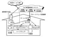
第三世代(2012年以降)のクラウド家電は、Wi-Fi(登録商標)、Bluetooth(登録商標)(以下BTとする)等の通信機能を持ち、ホームGW(ゲートウェイ)とブロードバンド回線網とを経由してIoT(Internet of Things)家電制御クラウドに接続可能になった。このため、出荷後もクラウドから本体内のマイコンのソフトウェアを更新することもできるようになった。マイコンのソフトウェアは更新しないで、クラウド側の該当機器の制御機構を更新すること等により、出荷後も機能追加、更新を行うことができるようになった。ここで、IoT家電制御クラウドとは、ブロードバンド回線網などの通信路を通じて家電機器を制御するクラウド(サーバとネットワークとの集合体)であり、クラウド型のサービスの1つである。 Third-generation (after 2012) cloud home appliances have communication functions such as Wi-Fi (registered trademark) and Bluetooth (registered trademark) (hereinafter referred to as BT), and connect home GW (gateway) and broadband network. It is now possible to connect to the IoT (Internet of Things) home appliance control cloud. For this reason, even after shipment, it is now possible to update the software of the microcomputer in the main unit from the cloud. By updating the control mechanism of the corresponding device on the cloud side without updating the software of the microcomputer, functions can be added and updated even after shipment. Here, the IoT home appliance control cloud is a cloud (collection of servers and networks) that controls home appliances through a communication channel such as a broadband network, and is one of cloud-type services.
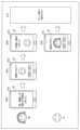
図2は、第三世代の生活家電のアーキテクチャと外部サービス連携の例を示す説明図である。 FIG. 2 is an explanatory diagram showing an example of the architecture of a third-generation home appliance and external service linkage.
第三世代のクラウド生活家電(洗濯機、冷蔵庫等の白物家電とエアコン、加湿)の場合は、スマートフォンのAPPs(アプリケーション)からIoT家電制御クラウドの各生活家電制御機構を経由して、家庭内の各生活家電にアクセスすることが可能になる。 In the case of third-generation cloud home appliances (white goods such as washing machines, refrigerators, air conditioners, and humidifiers), from smartphone APPs (applications) via each home appliance control mechanism of the IoT home appliance control cloud, in the home It becomes possible to access each home appliance of
このため、ユーザは、スマートフォンのAPPsを用いることで、各生活家電の動作状況の遠隔監視、遠隔動作制御(起動、停止、温度調節、洗剤投入等)などをすることができる。また、ECサービスクラウド又は見守りサービスクラウド等の外部サービス群と、IoT家電制御クラウド内の各生活家電制御機構とが連携することにより、各種クラウドサービスから生活家電を制御したり、生活家電の動作情報(ログ等)を取り出し、それを外部サービスで利用したりすることが可能になる。 Therefore, the user can remotely monitor the operation status of each home appliance and remotely control the operation (start, stop, temperature control, detergent injection, etc.) by using the APPs of the smartphone. In addition, external services such as the EC service cloud or the monitoring service cloud cooperate with each home appliance control mechanism in the IoT home appliance control cloud to control home appliances from various cloud services and provide operation information of home appliances. (Logs, etc.) can be extracted and used by external services.
図3は、第三世代の生活家電のアーキテクチャとAI(Artificial Intelligence、人工知能)スピーカー連携の例を示す説明図である。 FIG. 3 is an explanatory diagram showing an example of third-generation home appliance architecture and AI (Artificial Intelligence) speaker linkage.
第三世代のクラウド生活家電(洗濯機、冷蔵庫等の白物家電とエアコン、加湿)の場合は、音声対話機能を実現するAIスピーカーから、ホームGW経由でクラウド内のAIスピーカー制御機構にアクセスし、そのAIスピーカー制御機構が各生活家電制御機構にアクセスすることで、ユーザがAIスピーカーから音声対話で各生活家電を遠隔制御することも可能になる。 In the case of third-generation cloud home appliances (white goods such as washing machines, refrigerators, air conditioners, and humidifiers), the AI speaker that realizes the voice interaction function accesses the AI speaker control mechanism in the cloud via the home gateway. , the AI speaker control mechanism accesses each home appliance control mechanism, thereby enabling the user to remotely control each home appliance through voice interaction from the AI speaker.
(解決すべき課題)
図4は、第三世代の生活家電の第一の課題を示す説明図である。第一の課題は、Wi-Fi GWがない家庭では、第三世代の家電の機能を使うことができない、という課題である。(Problems to be solved)
FIG. 4 is an explanatory diagram showing the first problem of third-generation home appliances. The first problem is that homes without Wi-Fi GW cannot use the functions of third-generation home appliances.
ある家庭が第三世代のクラウド生活家電(洗濯機、冷蔵庫等の白物家電とエアコン、加湿)を購入した場合でも、その家庭にWi-Fi等のホームGWがなくブロードバンド回線網に接続できない場合は、クラウド家電がIoT家電制御クラウドに接続できない。この場合、IoT家電制御クラウドから家電にアクセスすることが不可能なため、第三世代の生活家電が掲げる、購入後のクラウド側での機能進化による商品付加価値向上という目的を達成することができない。そのため、IoT家電でありながら製造時に機能が固定されていた従来型の第二世代生活家電(マイコン生活家電)としてしか使用できない。 Even if a household purchases third-generation cloud-based household appliances (washing machines, refrigerators, and other white goods, air conditioners, and humidifiers), the household does not have a home gateway such as Wi-Fi and cannot connect to a broadband network. , cloud home appliances cannot connect to the IoT home appliance control cloud. In this case, it is impossible to access home appliances from the IoT home appliance control cloud, so it is not possible to achieve the purpose of improving the added value of products through functional evolution on the cloud side after purchase, which is set by third-generation home appliances. . Therefore, although it is an IoT home appliance, it can only be used as a conventional second-generation home appliance (microcomputer home appliance) whose functions were fixed at the time of manufacture.
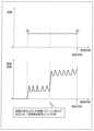
図5は、第三世代の生活家電の第二の課題を示す説明図である。第二の課題は、Wi-Fi GWが家庭にあってもユーザが第三世代の生活家電をWi-Fi GWに接続しない、という課題である。 FIG. 5 is an explanatory diagram showing the second problem of third-generation home appliances. The second problem is that even if a Wi-Fi GW is installed at home, users do not connect third-generation home appliances to the Wi-Fi GW.
スマートフォン、タブレット、PC等の情報機器、又は、AIスピーカーは、Wi-Fi等によるインターネット接続機能がないと、ユーザがその製品に望む本来の機能が使えない。また、スマートフォン又はAIスピーカーには、インターネットに接続し、ユーザ情報(メールアドレス、アカウント等)を設定しないと、そもそも使えない機器もある。ユーザはそれらの機能を使いたいためにその機器を購入したため、ユーザは必ずユーザID設定又はWi-Fi設定を行い、インターネットに接続させる。 Information devices such as smartphones, tablets, and PCs, or AI speakers cannot use the original functions that users want for the product without the Internet connection function such as Wi-Fi. Also, some smartphones or AI speakers cannot be used in the first place unless they are connected to the Internet and user information (e-mail address, account, etc.) is set. Since the user purchased the device in order to use those functions, the user always performs user ID setting or Wi-Fi setting to connect to the Internet.
スマートTVの場合も、Youtube、Netflix、Amazon Prime Video等の映像配信サービスが普及しており、これらの映像コンテンツを大画面TVで視聴するために、ユーザ(もしくは設置業者)がWi-Fiの設定を行うことが多い。 In the case of smart TVs as well, video distribution services such as YouTube, Netflix, and Amazon Prime Video are widespread, and in order to view these video contents on large-screen TVs, users (or installers) set up Wi-Fi. often do
クラウド生活家電の場合は、ユーザが面倒なWi-Fi設定を行ったことで利用可能になるインターネットサービスが判り難かったり、このインターネットサービスの利用価値性がユーザにとって必要な機能と思えなかったりするため、ユーザは最初からインターネット接続設定を行わないことが多い。 In the case of cloud home appliances, it is difficult for the user to understand the Internet service that becomes available after performing the troublesome Wi-Fi settings, and the utility value of this Internet service is not considered a necessary function for the user. , users often do not set up an Internet connection from the beginning.
また、購入直後において、ユーザは、Wi-Fi設定を行うが、インターネットサービスの利便性が比較的高くないと考えた場合、折角接続したものを解除する、または、何らかの理由で接続が切れても再接続しないことが多い。 In addition, immediately after purchase, the user performs Wi-Fi settings, but if he/she considers that the convenience of the Internet service is not relatively high, he or she cancels the connection that was made with great effort, or even if the connection is cut off for some reason, It often doesn't reconnect.
従って、情報機器とAIスピーカーとについてはほぼ100%接続が期待できるため、インターネットに接続されることを前提に各種クラウドサービスを開発することが可能であるが、TV又は生活家電の場合は、100%の接続率はほぼ期待されない。 Therefore, since almost 100% connectivity can be expected between information devices and AI speakers, it is possible to develop various cloud services on the assumption that they will be connected to the Internet. A connection rate of 10% is hardly expected.
図6は、ネット接続機能内蔵家電(AVと生活家電)のネット接続率を示す説明図である。 FIG. 6 is an explanatory diagram showing the network connection rate of home appliances (AV and household appliances) with a built-in network connection function.
前述のクラウド生活家電は、Wi-Fi又はBluetoothなどの通信手段が実装されることによって、IoT家電制御クラウドへの接続が実現され、各種クラウドサービスを利用することで、マイコン生活家電にない顧客価値を提供できる。このため、Wi-Fi等の通信手段をクラウド生活家電に実装することによるコスト増加を上回る顧客価値を提供できることで顧客満足度を向上させることができる。 The above-mentioned cloud home appliances can be connected to the IoT home appliance control cloud by implementing communication means such as Wi-Fi or Bluetooth, and by using various cloud services, customer value that is not found in microcomputer home appliances can provide For this reason, it is possible to improve customer satisfaction by providing customer value that exceeds the cost increase resulting from implementing communication means such as Wi-Fi in cloud home appliances.
しかしながら、前述の通信手段は、以下に示すような多くのケースで機器を保有するユーザによる設定がなされないという課題、つまりはクラウド生活家電がクラウドへ接続されないと、マイコン生活家電と同じ顧客価値しか提供できないという課題がある。 However, the above-mentioned communication means has the problem that in many cases as shown below, settings are not made by the user who owns the device. There is a problem that it cannot be provided.
(1)Wi-Fiを接続するためには、ユーザは宅内にWi-Fiのアクセスポイントを用意する必要がある。しかしながら、インターネットの接続はスマートフォンからしか行わないユーザ、つまり通信キャリアが用意する通信網しか使用しないユーザにとってWi-Fiのアクセスポイントを宅内に保有していないケースがある。 (1) In order to connect to Wi-Fi, the user needs to prepare a Wi-Fi access point at home. However, there are cases where users who connect to the Internet only from their smartphones, that is, users who only use communication networks provided by communication carriers do not have Wi-Fi access points in their homes.
(2)Wi-Fiのアクセスポイントが宅内に存在していたとしても、家電の接続設定の煩雑さ、例えばWi-Fiのパスワード入力を筆頭とする接続作業のために、万人が容易にWi-Fiの接続設定を出来るとは言い難い。 (2) Even if there is a Wi-Fi access point in the home, it is easy for everyone to connect to Wi-Fi because of the complexity of home appliance connection settings, for example, the need to enter a Wi-Fi password. -It is hard to say that you can set the connection of Fi.
実際、図6のように2017年の日本市場でのクラウド対応TV又はクラウド生活家電のネットワーク接続率は、50%以下に留まり、多くのユーザがクラウド生活家電をマイコン生活家電として使っていることがわかる。 In fact, as shown in Figure 6, the network connection rate of cloud-compatible TVs or cloud-based home appliances in the Japanese market in 2017 remained below 50%, indicating that many users are using cloud-based home appliances as microcomputer home appliances. Recognize.
図7は、クラウド生活家電のネット接続などを示す説明図である。 FIG. 7 is an explanatory diagram showing network connection and the like of cloud home appliances.
クラウド生活家電がクラウドに接続されていない場合、IoT家電制御クラウドからクラウド生活家電にアクセスすることが不可能である。このため、クラウド生活家電で実現可能な、購入後のクラウド側での機能進化による商品付加価値向上機能を利用することができない。 If the cloud home appliances are not connected to the cloud, it is impossible to access the cloud home appliances from the IoT home appliance control cloud. For this reason, it is not possible to use the product added value improvement function by function evolution on the cloud side after purchase, which can be realized with cloud home appliances.
そのため、クラウド生活家電でありながら、製造時に機能が固定されていた従来型のマイコン生活家電と同等の機能しか使えない。 Therefore, although it is a cloud home appliance, it can only use the same functions as conventional microcomputer home appliances whose functions were fixed at the time of manufacture.
本来のクラウド生活家電であれば、万が一リコールなどが発生した際にも対象家電に対して緊急停止指示、リモートファーム更新、又は、ユーザへのメール通知などの対応を取ることができる。しかし、接続率の低い、現状では、製造メーカは、これらのIoT家電制御クラウドから、クラウド生活家電を制御する機能をつかうことができないことが多い。このため、対象クラウド生活家電の全部に対して、遠隔監視、制御ができれば実現可能な、リモートメンテナンス又はリコール通知等の機能が十分機能しない。 In the case of the original cloud home appliances, even in the unlikely event of a recall, it is possible to take measures such as instructing the target home appliance to stop immediately, update the remote firmware, or notify the user by email. However, in the current situation where the connection rate is low, manufacturers often cannot use the function of controlling cloud home appliances from these IoT home appliance control clouds. For this reason, functions such as remote maintenance or recall notification, which can be realized if remote monitoring and control are possible, do not function sufficiently for all target cloud home appliances.
そこで、Wi-Fi又はBT等の通信手段が実装されたクラウド生活家電が、実際にはクラウドへ接続されづらい状況もあるなか、家電以外の機器又はセンサをIoT化するための様々な通信手段が利用可能になってきた。 Therefore, while it is difficult to actually connect cloud home appliances equipped with communication means such as Wi-Fi or BT to the cloud, there are various communication means for IoT devices or sensors other than home appliances. has become available.
特に、LPWA(Low Power Wide Area)と総称されるIoT向け利用に特化して開発された無線通信手段が実用化され、IoT時代に適した通信方式として注目されている。 In particular, wireless communication means developed specifically for use in IoT, collectively called LPWA (Low Power Wide Area), have been put into practical use and are attracting attention as a communication system suitable for the IoT era.
LPWA無線の特徴は、LTE(Long Term Evolution)に比べ、小規模の半導体実装により端末コストを削減できることと、非常に長い通信距離(~10km)が得られる低レート変調により基地局数を削減できることとによって、無線回路とインフラ設備との両方の低コスト化を実現したことである。反面、伝送レートを下げて受信感度を改善する手法を取っているため、伝送できるデータ量は小さい。 Compared to LTE (Long Term Evolution), the features of LPWA radio are that terminal costs can be reduced by small-scale semiconductor implementation, and that the number of base stations can be reduced by low-rate modulation that enables extremely long communication distances (up to 10km). As a result, the cost of both radio circuits and infrastructure equipment has been reduced. On the other hand, the amount of data that can be transmitted is small because the transmission rate is lowered to improve reception sensitivity.
LPWA無線を家電機器に搭載することにより、利用者がインターネット回線を契約する必要がなくなり、家電機器が直接的に基地局に接続されて、クラウドサーバに接続したサービスを非常に低コストに実現できる可能性がある。 By installing LPWA radio in home appliances, users do not need to make a contract for Internet lines, and home appliances are directly connected to a base station, making it possible to realize a service connected to a cloud server at a very low cost. there is a possibility.
LPWAは、セルラーLPWAとノンセルラーLPWAとに分類される。セルラーLPWAは、セルラーキャリアに割り当てられた周波数バンド(ライセンスバンド)を用い、セルラー回線(LTEなど)の1つとして提供されるものである。 LPWAs are classified into cellular LPWAs and non-cellular LPWAs. Cellular LPWA uses a frequency band (licensed band) assigned to a cellular carrier and is provided as one of cellular lines (such as LTE).
ノンセルラーLPWAは、各国に存在するノンライセンスバンドを用いてチャネル使用費用が不要となることを利用してLPWA無線を使用するものである。ノンライセンスバンドは他の無線システムとの共用利用となるため、チャネルを独占しないための制限が各国の電波法で規定されている。 Non-cellular LPWA utilizes LPWA radio by using non-licensed bands existing in each country and eliminating channel usage costs. Since non-licensed bands are used in common with other radio systems, restrictions are stipulated by the Radio Law of each country so as not to monopolize the channel.
以下に代表的なLPWA方式について述べる。 A typical LPWA system will be described below.
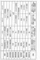
図8は、常時接続IoT生活家電で利用可能な通信方式(Wi-Fi、LPWA)の特徴を示す表である。 FIG. 8 is a table showing the characteristics of communication methods (Wi-Fi, LPWA) that can be used in constant-connection IoT home appliances.
(1)セルラーLPWA
(1-1)NB-IoT
GSM(登録商標)(2G)方式を起源とし、低伝送レート化とLTE通信シーケンスの優位性を適用し、IoT向けのデータ伝送に特化した仕様となっている。チャンネル間隔をGSMと同じ200kHzにすることで、GSMチャネルへの置換え運用を容易にしている。上り送信のピークレートを62.5kbpsと低速化し、また複数回の繰返し送信(64回)で蓄積受信することで、感度点の改善を行っている。最大リンクバジェットは130dBと大きい。また、送信電力を100mW(GSMは2W)に抑える仕様とし、ピーク電流を抑えて電池1本での運用を可能としている。(1) Cellular LPWA
(1-1) NB-IoT
Originating from the GSM (registered trademark) (2G) system, it applies the low transmission rate and superiority of the LTE communication sequence, and has specifications specialized for data transmission for IoT. By setting the channel interval to 200 kHz, which is the same as GSM, it facilitates replacement operation with GSM channels. The sensitivity point is improved by lowering the peak rate of uplink transmission to 62.5 kbps and accumulating/receiving multiple repetitions of transmission (64 times). The maximum link budget is as large as 130 dB. In addition, the transmission power is set to 100mW (2W for GSM), which suppresses the peak current and enables operation with a single battery.
(1-2)LTE-M(CAT-M)
LTE(4G)方式を起源とし、LTEの最小チャネル間隔(1.4MHz)を用いて通信を行う方式である。LTEのスロット構成に準拠しているため、従来LTEの通信スロットに混在させて運用することができる。上り送信のピークレートを1Mbpsと低速化し、繰り返し送信で蓄積受信することで、感度点の改善を行っている。最大リンクバジェットは130dBである。(1-2) LTE-M (CAT-M)
It originates from the LTE (4G) system and is a system that performs communication using the minimum channel spacing (1.4 MHz) of LTE. Since it conforms to the slot configuration of LTE, it can be used in combination with conventional LTE communication slots. The sensitivity point is improved by lowering the peak rate of uplink transmission to 1 Mbps and accumulating and receiving by repeated transmission. The maximum link budget is 130 dB.
伝送レートがやや高いため、電池駆動時の消費電力が最も小さい。送信電力は200mWである。 Since the transmission rate is rather high, power consumption is the lowest when powered by batteries. The transmission power is 200mW.
(2)ノンセルラーLPWA
(2-1)LoRa
従来の小電力無線バンド(ISMバンド)を用いるが、超低レート変調により受信感度を改善している。超低レート変調の実現方法は、LoRaチャープ変調と呼ばれる特殊な拡散変調を用いる。LoRaチャープ変調の特徴は、250bpsの低伝送レートと拡散帯域125kHzとを実現し、妨害ノイズに強く高感度が得られることである。また、同一帯域幅で複数のデータレートを選択でき、これらを同一チャネルで同時に受信できるので、通信容量のキャパシティが改善される。最大リンクバジェットは149dBである。送信電力は20mWである。(2) Non-cellular LPWA
(2-1) LoRa
It uses the conventional low-power radio band (ISM band), but uses ultra-low-rate modulation to improve receiver sensitivity. A very low rate modulation implementation uses a special spread modulation called LoRa chirp modulation. The characteristics of LoRa chirp modulation are that it achieves a low transmission rate of 250 bps and a spread band of 125 kHz, and is highly sensitive to interference noise. Also, multiple data rates can be selected with the same bandwidth and can be received simultaneously on the same channel, thereby improving communication capacity. The maximum link budget is 149 dB. The transmission power is 20mW.
従来の小電力無線の特徴(小電力、小電流ピーク)を継承しており、電池1本で10年駆動又はコイン電池での駆動が可能である。 It inherits the characteristics of conventional low-power radio (low power, low current peak), and can be driven for 10 years with a single battery or with a coin battery.
LoRa Allianceで仕様を統一し、事業者間の相互接続を可能とした。 The LoRa Alliance standardized specifications and enabled interconnection between operators.
(2-2)SIGFOX
従来の小電力無線バンド(ISMバンド)を用いるが、超低レート変調により受信感度を改善している。超低レート変調の実現方法は、狭帯域FSK変調であり、基地局側でデジタル復調処理を工夫することで、周波数誤差の問題を克服した。SIGFOX変調では、上り100bps、下り600bpsの固定レートとなる。周波数を変えた複数回送信をすることで妨害ノイズの影響を回避している。固定レートおよび同時多重受信不可のため、通信容量のキャパシティは比較的小さい。最大リンクバジェットは158dBである。送信電力は20mWである。(2-2) SIGFOX
It uses the conventional low-power radio band (ISM band), but uses ultra-low-rate modulation to improve receiver sensitivity. The ultra-low rate modulation is realized by narrowband FSK modulation, and the frequency error problem was overcome by devising digital demodulation processing on the base station side. SIGFOX modulation has a fixed rate of 100 bps for upstream and 600 bps for downstream. By transmitting multiple times with different frequencies, the influence of interference noise is avoided. The communication capacity is relatively small due to the fixed rate and the inability of simultaneous multiplex reception. The maximum link budget is 158dB. The transmission power is 20mW.
SIGFOXは、従来の小電力無線の特徴(小電力、小電流ピーク)を継承しており、電池1本で10年駆動又はコイン電池での駆動が可能である。 SIGFOX inherits the characteristics of conventional low-power radio (low power, low current peak), and can be driven for 10 years with a single battery or with a coin battery.
SIGFOX独自仕様となり、基地局をSIGFOX1社で独占する形態をとる。 SIGFOX will have its own specification, and the base station will be monopolized by SIGFOX.
SIGFOXは、片方向通信しかできないため、センサ系IoTには使えるが、IoT生活家電には適さない。 SIGFOX can only perform one-way communication, so it can be used for sensor-based IoT, but it is not suitable for IoT home appliances.
図8に示されるように、常時接続IoT生活家電を実現するためには、LPWA技術とWi-Fiとの組み合わせが適切と考えられる。しかしながら、上述したような3方式のLPWAの特質はそれぞれ異なるため、通信品質を重視すればコストが高くなり、反対にコストを重視すると通信品質が悪く安定的な通信が確保できないリスクがある。このため、常時接続IoT家電が1つの方式のLPWAを選択することは難しい。 As shown in FIG. 8, a combination of LPWA technology and Wi-Fi is considered appropriate for realizing always-connected IoT home appliances. However, since the characteristics of the three types of LPWA are different, if communication quality is emphasized, the cost will increase, and if cost is emphasized, the communication quality will be poor and stable communication cannot be ensured. Therefore, it is difficult for an always-connected IoT home appliance to select one type of LPWA.
(実施の形態)
以降において、適切に制御クラウドに接続され、制御され得る機器について説明する。(Embodiment)
In the following, devices that can be suitably connected to and controlled by the control cloud will be described.
図9は、第四世代の生活家電(常時接続IoT家電)のアーキテクチャと外部サービス連携を示す第一の説明図である。生活家電は、例えば、洗濯機、冷蔵庫等の白物家電とエアコン、加湿空気清浄機であり、単に機器ともいう。 FIG. 9 is a first explanatory diagram showing the architecture of fourth-generation household appliances (always-connected IoT appliances) and external service linkage. Home appliances include, for example, white goods such as washing machines and refrigerators, air conditioners, and humidifying air purifiers, and are also simply referred to as appliances.
第三世代の生活家電の課題を解決するためには、生活家電を利用する全てのユーザがWi-Fi GWを持ち、生活家電をインターネットに接続し継続的に利用したいと思わせるサービス開発を行い、かつ、簡単にWi-Fi設定をできるようにする必要があった。 In order to solve the problems of third-generation home appliances, we will develop a service that will make all users of home appliances have Wi-Fi GW, connect them to the Internet, and make them want to use them continuously. And it was necessary to be able to set Wi-Fi easily.
しかし、近年多様な通信手段の台頭により従来よりも簡単に家電をクラウドに接続できる、LPWA(Low Power Wide Area)と総称される通信手段が提唱され、注目されている。 However, in recent years, with the emergence of various communication means, a communication means generically called LPWA (Low Power Wide Area) has been proposed and is attracting attention, which enables home appliances to be connected to the cloud more easily than before.
LPWAの特徴は、ユーザが設定することなく利用することができ、非常に長い通信距離(~10km)を実現し、電波の届くところなら必ず基地局につながることである。 The features of LPWA are that it can be used without user settings, achieves a very long communication distance (up to 10 km), and connects to a base station wherever radio waves reach.
第四世代の生活家電(常時接続IoT家電)においては、LPWAを生活家電に搭載することにより、ユーザがWi-Fi GWを用意し、面倒なWi-Fi設定をすることなく、クラウドと接続することが可能となり、購入後のクラウド側での機能拡張などが可能となる。 In fourth-generation home appliances (always-connected IoT home appliances), by installing LPWA in home appliances, users prepare Wi-Fi GW and connect to the cloud without troublesome Wi-Fi settings. It is possible to expand functions on the cloud side after purchase.
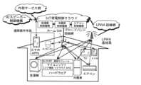
図10は、第四世代の生活家電のアーキテクチャと外部サービス連携を示す第二の説明図である。 FIG. 10 is a second explanatory diagram showing the architecture of fourth-generation home appliances and external service linkage.
LPWAは、前述の通り優れた特徴を持つ反面、伝送レートを下げて受信感度を改善する手法を取っているため、伝送できるデータ量はWi-Fi又はLTEなどに比べて小さい。そのため、第四世代の生活家電(以下、「常時接続IoT家電」とも言う。)においてはLPWAだけでなく、第三世代の生活家電同様Wi-Fiも併せ持つことで用途に応じた適切な通信を可能とする。 LPWA has excellent features as described above, but on the other hand, the amount of data that can be transmitted is smaller than that of Wi-Fi or LTE because it employs a method of lowering the transmission rate to improve reception sensitivity. Therefore, fourth-generation home appliances (hereinafter also referred to as “always-connected IoT home appliances”) have not only LPWA, but also Wi-Fi, like third-generation home appliances, to enable appropriate communication according to the application. make it possible.
図11は、第四世代の生活家電のアーキテクチャと外部サービス連携を示す第三の説明図である。 FIG. 11 is a third explanatory diagram showing the architecture of fourth-generation home appliances and external service linkage.
第三世代の生活家電の大きな課題の一つであった、ユーザに面倒なWi-Fi設定を強いるという点も、以下に例を示すようにLPWAをWi-Fi設定に活用することで設定を簡単にすることができる。 One of the major issues with third-generation household appliances is that users are forced to make complicated Wi-Fi settings. can be simplified.
(1)クラウドにWi-Fi設定を入力し、第四世代の生活家電はLPWAを利用して、クラウドからWi-Fi設定を取得しWi-Fi GWに接続する。 (1) Input Wi-Fi settings to the cloud, and the fourth-generation household appliances use LPWA to obtain the Wi-Fi settings from the cloud and connect to the Wi-Fi GW.
(2)一台の第四世代の生活家電にWi-Fi設定を入力し、LPWA経由で、宅内他機器に送信、他機器はその設定を用いてWi-Fi GWに接続する。 (2) Input Wi-Fi settings into one fourth-generation home appliance, transmit to other home devices via LPWA, and connect to Wi-Fi GW using the settings.
図12は、生活家電のアーキテクチャの進化を示す図である。 FIG. 12 is a diagram showing the evolution of the architecture of home appliances.
第一世代(1990年以前)の生活家電機器は、例えばコンプレッサ、モータ等のメカニクスと制御ロジックとにより実現された単機能製品である。 First-generation (before 1990) home appliances are single-function products realized by mechanics and control logic, such as compressors and motors.
第二世代(2010年くらいまで)の生活家電機器は、マイコンを内蔵しており、マイコンにマイコンソフトを実行させることにより、複雑な制御が可能となった。このため、第二世代の生活家電機器は、多機能である。ただし、第二世代の生活家電機器は、出荷後において、マイコンソフトを変更することで機能を変更したり、追加したりすることは困難であった。 Second-generation (until about 2010) home electric appliances have a built-in microcomputer, and by causing the microcomputer to execute microcomputer software, complicated control becomes possible. Therefore, second-generation home appliances are multifunctional. However, it was difficult to change or add functions by changing the microcomputer software after shipment of second-generation home appliances.
第三世代(2012年以降)のクラウド家電は、Wi-Fi、Bluetooth等の通信機能を持ち、ホームGWとブロードバンド回線網とを経由してIoT家電制御クラウドに接続可能になった。このため、クラウド家電は、出荷後であってもIoT家電制御クラウドから本体内のマイコンソフトを更新することも、マイコンソフトを更新しないで、クラウド側の該当機器の制御機構を更新すること等により、機能の追加または機能の更新を行うことができるようになった。ただし、Wi-Fi等では、出荷された全製品を接続することが難しく、クラウド機能が使えない場合が多かった。 Third-generation (after 2012) cloud home appliances have communication functions such as Wi-Fi and Bluetooth, and can be connected to the IoT home appliance control cloud via home GW and broadband network. For this reason, cloud home appliances can update the microcomputer software in the main body from the IoT home appliance control cloud even after shipment, or update the control mechanism of the corresponding device on the cloud side without updating the microcomputer software. , it is now possible to add features or update features. However, with Wi-Fi, etc., it was difficult to connect all the shipped products, and in many cases cloud functions could not be used.
第四世代(2020年以降)LPWA等の常時接続機能を搭載した常時接続IoT家電では、出荷された全製品を接続することができるため、クラウドの機能がすべての製品で利用可能になると考えられている。 With fourth-generation (after 2020) always-connected IoT home appliances equipped with always-connected functions such as LPWA, all shipped products can be connected, so cloud functions will be available for all products. ing.
図13は、第四世代の生活家電の機能分担(機能の外部化)について説明するための図である。 FIG. 13 is a diagram for explaining the division of functions (externalization of functions) of fourth-generation household appliances.
第四世代のクラウド生活家電(洗濯機、冷蔵庫等の白物家電とエアコン、加湿空気清浄機等)の場合は、生活家電と、クラウド(サーバ)と、スマートフォン等のUI機器との間を常時接続機能で繋ぐことで、クラウドと、スマートフォンと、生活家電などの機器とに機能分担(機能の外部化)を実現することができる。このため、機器が出荷された後も、クラウド側で機能変更や追加を行うことで、生活家電の機能・性能改善が可能となる。 In the case of fourth-generation cloud home appliances (washing machines, refrigerators and other white goods, air conditioners, humidifying air purifiers, etc.), there is always a connection between the home appliances, the cloud (server), and UI devices such as smartphones. By connecting with the connection function, it is possible to realize the sharing of functions (externalization of functions) among the cloud, smartphones, and devices such as household appliances. Therefore, even after the device is shipped, it is possible to improve the function and performance of home appliances by changing or adding functions on the cloud side.
また、第四世代のクラウド生活家電では、出荷された製品の全数の常時接続を容易に実現できるため、出荷後も全製品の遠隔監視および遠隔制御が可能となる。このため、品質保証機能の大幅改善が期待できる。また、不幸にも製品をリコールするような事態になっても、クラウドは、出荷後も機器と通信接続され、トレースできるため、リコールの対象製品に対し、故障の告知、強制停止等の対応を実行できる。このため、リコール費用の大幅低減が可能となる。 In addition, with fourth-generation cloud-based household appliances, it is easy to achieve constant connectivity for all shipped products, enabling remote monitoring and remote control of all products even after shipment. Therefore, a significant improvement in the quality assurance function can be expected. In addition, even in the unfortunate event that a product is recalled, the cloud is connected to the equipment even after shipment and can be traced. can run. As a result, recall costs can be significantly reduced.
図14は、4層の顧客接点と常時接続IoT家電との関係を示す図である。 FIG. 14 is a diagram showing the relationship between customer contact points on the four layers and always-connected IoT home appliances.
携帯キャリアは、フィーチャーフォンで完璧なプラットホーム(機器ID、個人情報、位置情報、決済手段等)を構築した。 Mobile carriers have built a perfect platform (device ID, personal information, location information, payment methods, etc.) with feature phones.
次に、携帯音楽プレーヤー、スマートフォンなどの登場により、クラウドサービス側を奪取され、携帯キャリアにより構築されたエコシステムが弱体化した。 Next, with the advent of portable music players, smartphones, etc., the cloud service side was taken over, weakening the ecosystem built by mobile carriers.
将来では、常時接続に対応する第四世代の常時機器IoT家電の登場により、クラウドに常時接続できる機器ID(クラウド連携ID)を確保することで、顧客接点の取得に活用することができると考えられる。 In the future, with the advent of fourth-generation constant-device IoT home appliances that support constant connectivity, we believe that by securing a device ID (cloud-linked ID) that can always connect to the cloud, it will be possible to use it to acquire customer contact points. be done.
図15は、機器管理システムにおける家電機器の稼働状態データの収集フローを示す図である。図16は、クラウドが受信する家電機器の稼働情報および固有情報の具体例を示す表である。 FIG. 15 is a diagram showing a flow of collecting operating state data of home electric appliances in the appliance management system. FIG. 16 is a table showing a specific example of operation information and unique information of home appliances received by the cloud.
図15に示されるように、機器管理システム1は、サーバ20と、基地局30と、複数の機器10とを備える。 As shown in FIG. 15, the
サーバ20は、インターネットなどのネットワークに通信接続されており、IoT家電制御クラウドとして機能する。サーバ20の詳細な機能については後述する。 The
基地局30は、例えばLPWA基地局であり、IoT家電がネットワークに常時接続するための遠距離無線通信に用いられる基地局である。図15では、1つの基地局30が図示されているが、機器管理システム1は、複数の基地局30を備える。 The
複数の機器10のそれぞれは、上述した第四世代の生活家電、つまり、常時接続IoT家電であり、複数の基地局30のうちの一の基地局30に通信接続する。各機器10は、当該機器10の現在の稼働状態を示す稼働状態データ(以下、「稼働情報」とも言う。)を、当該機器10に内蔵されているLPWA通信モジュールを用いて、一の基地局30を経由してサーバ20に逐次送信する。 Each of the plurality of
なお、稼働情報は、図16に示されるように、「機器固有ID」、「通信モジュールID」、「通信モジュール種別」、「送信日時」、「電源状態」、「稼働回数のカウント開始日時」、「稼働回数」などのデータ項目を含む。稼働情報は、これらのデータ項目以外にもソフトウェアのバージョン情報、部材変更があった場合などはその差分情報を管理する情報、設定されているメニュー項目、モード設定などの情報を含んでいてもよい。これにより、サーバ20は、機器10がどのような状態で動作しているのかをより正確に管理することができる。また、稼働情報に含まれるデータ項目は、優先度や送信頻度が設定されていてもよく、データ送信時に毎回記載する項目、週に一度だけ記載する項目、変化があった場合のみ記載する項目など差をつけることで送信データサイズを削減してもよい。特に、通信モジュールが外部電源ではなく、内部のバッテリで動作しているケースなどでは消費電力を抑えるために重要なデータ項目だけ送信するなどの使い方が有用である。 As shown in FIG. 16, the operation information includes "equipment unique ID", "communication module ID", "communication module type", "transmission date and time", "power supply status", and "operation count start date and time". , including data items such as “operation count”. In addition to these data items, the operating information may include information such as software version information, information for managing difference information when there is a component change, set menu items, and mode settings. . As a result, the
次に、基地局30は、稼働情報を逐次受信すると、逐次受信された稼働情報と共に当該基地局30に固有の情報である固有情報をサーバ20に逐次送信する。ここで、基地局30が稼働情報を転送する際に、稼働情報と共に送信される固有情報は、図16の表の最下段に示されるように、固有情報を送信する基地局30が設置されている位置を示す位置情報である。また、固有情報は、位置情報に限らずに、基地局30を識別する識別子であってもよい。以下では、固有情報として位置情報を例にして説明する。 Next, when the
次に、機器10およびサーバ20の構成についてそれぞれ説明する。 Next, configurations of the
図17は、IoT家電である機器10のブロックを示す構成図である。 FIG. 17 is a configuration diagram showing blocks of the
図17に示されるように、機器10は、通信モジュール101と、制御部104と、機能モジュール107と、保持部108と、電源部109と、バッテリ110と、操作部111と、表示部112とを備える。 As shown in FIG. 17,
通信モジュール101は、機器10を管理するサーバ20に、互いに異なる複数の回線網を介して接続する。通信モジュール101は、例えば、LPWAなどの遠距離無線通信を行うための通信モジュールである。なお、通信モジュール101は、図8を用いて説明した、3方式のLPWAおよびWi-Fiのうちの少なくとも1方式のLPWAを行う通信モジュールを含んでいてもよい。つまり、通信モジュール101は、複数の方式のLPWAをそれぞれ行う、複数の通信モジュールを含んでいてもよいし、LPWAおよびWi-Fiをそれぞれ行う複数の通信モジュールを含んでいてもよい。通信モジュール101は、通信モジュールのモジュールIDを保持している保持部102を有する。通信モジュール101は、通信方式が異なる複数の通信モジュールを有している場合には、保持部102は、複数の通信モジュールのそれぞれのモジュールIDを保持している。
制御部104は、機器10の稼働情報を生成し、生成された稼働情報を、通信モジュール101を用いてサーバ20に送信する。制御部104は、具体的には、機器10の電源部109の電源の入/切を示す電源状態を取得することで電源状態を含む稼働情報を生成してもよいし、機器10が稼働した回数を示す稼働回数をカウントすることで稼働回数を含む稼働情報を生成してもよいし、機能モジュール107が発揮している機能を示す機能情報を含む稼働情報を生成してもよい。稼働情報は、図16で説明した各種データ項目を含んでいてもよい。また、制御部104は、通信モジュール101を介してサーバ20から受信した情報に基づく画像を表示部112に表示させてもよい。 The
機能モジュール107は、機器10の機能を発揮するモジュールである。 The
保持部108は、機器10ごとの固有のIDを保持している記憶装置である。 The holding
電源部109は、外部電源から電力を受け、機器10内部の構成要素に電力を供給する。 The
バッテリ110は、通信モジュール101などに電力を供給する電池である。バッテリ110は、一次電池であってもよいし、二次電池であってもよい。 A
操作部111は、機器10に対するユーザによる操作を受け付ける入力装置である。操作部111は、機器10が冷蔵庫、電子レンジ、炊飯器などのように、開閉するドア、扉などを有する場合、これらのドア、扉などであってもよい。 The
表示部112は、さまざまな情報を画像として表示する表示装置である。 The
機器10の構成について、冷蔵庫を例として詳しく説明する。 The configuration of the
IoT機器としてネット接続されているとしても、冷蔵庫である機器10は、家電として利用されるものであり、家電として本来の機能を実現するための各種モジュールを備えている。冷蔵庫であれば、庫内を冷却するためのコンプレッサ、扉が開かれた際に庫内を照らす照明装置、庫内の温度又は湿度を測定するためのセンサなどがこうしたモジュールにあたる。このようなモジュールが機能モジュール107に相当する。また、冷蔵庫又はエアコンなどの大型家電機器は、電源部109を介して外部電源に接続される構成が一般的である。 Even though it is connected to the Internet as an IoT device, the
また、近年の家電機器では様々な便利機能を制御するために、マイクロコンピューター又はプロセッサを用いた制御部104が搭載されていることが一般的である。例えば、製氷機能を持つ冷蔵庫であれば、製氷された氷を保存しておく専用皿内に設置されたセンサで製氷の是非を判断し、新たな氷を作るような動作を行う。こうした詳細な動作を行うために、マイクロコンピューター又はプロセッサと、そこで実行されるソフトウェアによって制御が行われている。 Further, in recent years, home electric appliances are generally equipped with a
さらに、機器10は、ユーザに対して様々な情報を提示するための表示部112、又は、ユーザが複雑な操作を行うための操作部111をもつ。 Furthermore, the
従来の機器の表示部は、複数のランプ又は数桁の数字での表示など限定的な方法で、異常状態の表示又は通電の有無など最低限必要な表示だけを行っていた。また、操作も数個のボタンだけで、急速冷凍の指示又は異常時のリセット操作などシンプルな操作を行ってきた。 The display unit of the conventional equipment used a limited method, such as a display with a plurality of lamps or numbers of several digits, to display only the minimum required display such as the display of an abnormal state or the presence or absence of electricity. In addition, simple operations such as instructing quick freezing or resetting in the event of an abnormality have been performed with only a few buttons.
これに対して、機器10は、小型のタッチパネルディスプレイを、操作部111及び表示部112として備え、より複雑な状態の表示、及び、各種の設定が可能である。 On the other hand, the
機器10に対し、IoT家電を特徴付けるものが、通信モジュール101である。通信モジュール101は、Wi-Fi又はLTEなど様々な通信手段のなかのいずれか、または複数の方式でインターネットへの接続を可能とする。通信モジュールが複数搭載されている場合にはそれぞれ通信モジュールごとに独立した通信モジュールIDが付与され、通信方式によっては例えばLTEにおける電話番号のように通信識別子としての役割をになう。インターネットと接続することにより、制御部104で収集した各種情報をサーバ20に送付すること、又は、反対にサーバ20から機器10の制御に必要となる情報を取得することが可能である。さらに、近年ではLPWAと呼ばれる、通信速度は低いものの、低消費電力でネット接続が可能な技術も出てきている。LPWAでは、外部電源とは別に機器10内にバッテリ110を持つことで、外部電源に接続されていない場合でも最低限の通信が可能となる。また、通信によっては、特定の家電機器を指定して制御を行う必要もあるため、機器10ごとの固有IDを保持する保持部108を備えることも想定される。 The
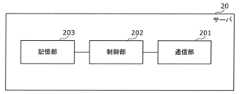
図18は、IoT家電制御クラウドであるサーバ20のブロックを示す構成図である。 FIG. 18 is a configuration diagram showing blocks of the
図18に示されるように、サーバ20は、通信部201と、制御部202と、記憶部203とを有する。 As shown in FIG. 18 , the
通信部201は、インターネットなどのネットワークに通信接続することで、機器10により逐次送信された稼働情報および位置情報を逐次受信する。また、通信部201は、ネットワークを介してユーザの操作機器40から第1ユーザIDと機器10を識別する識別子である第1機器IDとの対応付けの要求を示す要求情報を受信する。また、通信部201は、制御部202の処理結果をネットワークおよび基地局30を介して、機器10に送信してもよい。 The
制御部202は、通信部201により互いに対応するタイミングで逐次受信された稼働情報および位置情報を対応付けて逐次記憶部203に記憶する。また、制御部202は、通信部201により受信された要求情報により示される要求を受け付け、受け付けられた要求に応じて第1機器IDと第1ユーザIDとを対応付けて記憶部203に記憶する。制御部202は、所定のプログラムを実行することで、記憶部203に記憶された稼働情報または位置情報を用いた処理結果を通信部201に機器10へ送信してもよい。 The
制御部202は、所定のプログラムを記憶している不揮発性メモリと、所定のプログラムを実行するプロセッサとにより実現される。制御部202は、上記の機能を実現する専用回路により実現されてもよい。 The
記憶部203は、通信部201により受信された稼働情報および位置情報を記憶する。また、記憶部203は、第1機器IDと第1ユーザIDとを対応付けて記憶する。記憶部203は、機器を識別する機器IDと、ユーザを識別するユーザIDとが対応付けられている対応関係を記憶していてもよい。対応関係は、当該対応関係においてユーザIDに対応付けられている機器IDで識別される機器が、当該ユーザIDで示されるユーザに所有されていることを示す情報である。記憶部203は、制御部202による処理結果を記憶してもよい。記憶部203は、例えば、HDD(Hard Disk Drive)、SSD(Solid State Drive)などにより実現される。
次に、家電機器の状態予測、例えば、家電機器が「一般家庭へ設置されたこと」の予測方法について説明する。 Next, a method of predicting the state of a home appliance, for example, a method of predicting that a home appliance is "installed in a general household" will be described.
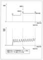
図19および図20は、機器10が一般家庭へ設置されたことを検知する方法について説明するためのグラフである。 19 and 20 are graphs for explaining a method of detecting that the
機器10は、ユーザに購入され、一般家庭に設置されることで始めて、ユーザとの間に関係が生まれる。つまり、機器10が一般家庭へ設置されたタイミングを、ユーザ利用開始として考えることもできるため、当該タイミングを検知することは非常に重要となる。 The
機器10が一般家庭へ設置されたタイミングを検知する方法は複数考えられる。 A plurality of methods are conceivable for detecting the timing when the
例えば、サーバ20は、機器10が最初に通電された際に、ユーザに確認することで機器10が一般家庭に設置されたと判定してもよい。この場合、機器10において、ユーザに機器10が一般家庭に設置されたことを確認するUI(User Interface)を表示部112に表示し、操作部111からの入力を受け付けることで、機器10が一般家庭に設置されたか否かを確認してもよい。この場合、機器10は、最初に家電量販店の店頭で通電されるケースも考えられるが、「利用を開始しますか?」などの質問を表示し、Noの場合は続けて「店頭利用ですか?」などを表示し、当該表示への回答を受け付けることで、店頭利用とユーザの一般家庭による利用とを区別することが考えられる。また、使用開始日、稼働回数などの稼働情報は、ユーザが利用するタイミングから蓄積していき、店頭利用時は情報をリセットしてもよい。 For example, the
つまり、サーバ20の制御部202は、逐次受信された複数の固有情報のうち、第1のタイミングで受信された第1固有情報と、第1のタイミングの次の第2のタイミングで受信された第2固有情報とが異なるか否かを判定し、第1固有情報と第2固有情報とが異なる場合、第1のタイミングまでの第1期間において受信された複数の第1稼働情報と、第2のタイミング以降の第2期間において受信された複数の第2稼働情報とを分けて管理する。つまり、第1期間は、機器10がユーザに購入される前の期間であることを示し、第2期間は、機器10がユーザに販売された後において当該ユーザに所有されている期間であることを示す。 That is, the
制御部202は、具体的には、複数の第1稼働情報を第1識別子と対応付けて記憶し、かつ、複数の第2稼働情報を第1識別子とは異なる第2識別子と対応付けて記憶部203に記憶することで、複数の第1稼働情報と、複数の第2稼働情報とを分けて管理してもよい。第1識別子は、例えば、販売前であり家電量販店などに位置する場合を示す識別子である。第2識別子は、第2期間において少なくとも1つの機器を利用しているユーザに対応付けられていることを示す識別子である。例えば、第2識別子は、一般家庭のユーザにより購入された後に、当該ユーザの家の中に設置されたことを示す識別子である。なお、複数の第1稼働情報は、ユーザの利用開始が検知された後において、記憶部203から削除されてもよい。 Specifically, the
なお、第1識別子は、第1のユーザに所有されていることを示す識別子とし、第2識別子は、第1のユーザとは異なる第2のユーザに所有されていることを示す識別子としてもよい。 Note that the first identifier may be an identifier indicating possession by the first user, and the second identifier may be an identifier indicating possession by a second user different from the first user. .
また、例えば、サーバ20は、機器10の操作部111がユーザから特定の利用操作を受け付けた場合に、機器10が一般家庭に設置されたと判定してもよい。特定の利用操作は、具体的には、機器10が洗濯機であれば注水を検知した場合、炊飯器であれば実際に炊飯が始まって蒸気を検知した場合に、行われたことが判定されてもよい。このように、特定の利用操作は、実際に販売される前に利用されることが考えにくい操作であることが好ましい。また、特定の利用操作とは、エアコンのように設置工事が必ずある機器であれば、工事事業者による設置設定の一部が行われたことを検知した場合に、特定の利用操作が行われたと判定されてもよい。 Further, for example, the
また、例えば、サーバ20は、逐次受信した位置情報を用い、機器10の位置が例えば家電量販店、流通倉庫などのような除外範囲の外の位置を示す場合、一般家庭に設置されたと判定してもよい。除外範囲を示す情報は、記憶部203に予め記憶されていてもよいし、通信部201により外部装置から取得されてもよい。なお、都市部では、この判定方法だけでは不十分だが、False Positive(誤って一般家庭に設置されたと判定する)はないため、利用することが望ましい。なお、除外範囲は、図21に示されるように、予め定められた範囲に限らずに、機器10が内蔵バッテリを有する通信モジュールを有していれば、通電されていない機器10が多く集まる場所としてもよい。これにより、コストをかけずに常に最新の除外範囲を定めることができる。図21は、除外範囲を、複数の機器から送信される稼働情報および位置情報を用いて決定する例を示す図である。 Further, for example, the
本実施の形態に係るサーバ20は、第1のタイミングで受信された第1固有情報と、第1のタイミングの次の第2のタイミングで受信された第2固有情報とが異なる場合、第1のタイミングまでの第1期間において受信された複数の第1稼働情報と、第2のタイミング以降の第2期間において受信された複数の第2稼働情報とを分けて管理する。このため、現在の機器のユーザの使用に基づく稼働情報を管理するため、ユーザの使用状態に適した機器の状態を判定することができる。このように、当該ユーザ以外のユーザなどによる使用に基づく稼働情報を除外して機器の管理を行うことができるため、機器の管理を効率よく行うことができる。 When the first unique information received at the first timing is different from the second unique information received at the second timing subsequent to the first timing, the
また、ユーザが使用している第2期間中に取得された稼働情報および固有情報に基づく機器の状態の判定を、第1期間中に取得された稼働情報および固有情報とは分けて行うことができる。このため、機器の状態の判定を精度よく行うことができる。 Further, the determination of the state of the device based on the operation information and the unique information acquired during the second period of use by the user can be performed separately from the operation information and the unique information acquired during the first period. can. Therefore, it is possible to accurately determine the state of the device.
次に、機器10の生涯管理のうちの家電購入および設置において行われる処理の一例について説明する。 Next, an example of processing performed in the purchase and installation of a home appliance in lifetime management of the
一般家庭での利用が開始した際に、機器10が稼働情報などのログを送信することは、プライバシ保護の観点から問題がある可能性もある。機器10のログは、ユーザのIDと紐付けられないかぎりは日本の法律における個人情報とはならないが、ユーザの心情として気持ち悪さが残る可能性がある。そのため、一般家庭での利用が開始されたと判断される場合には、一旦、機器10は、ログをサーバ20に送信することを停止することが望ましい。ただし、機器10がメッセージを表示できる表示部112を有する場合には、ログをサーバ20に送信することを説明した上で同意を求め、同意が得られれば引き続き機器10がログを送信し続けることも考えられる。 There is a possibility that there is a problem from the viewpoint of privacy protection that the
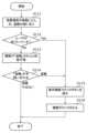
図22は、機器10を設置の際のログ送信の同意を得るための処理を示すフローチャートである。 FIG. 22 is a flowchart showing processing for obtaining consent for log transmission when the
なお、ここでは機器10は、通信モジュール101を備える機器であるため、ネットワークに接続する設定の必要はないものとしている。 Here, since the
まず、機器10は、購入され、ユーザの家に設置される(S1)。このとき、機器10は、店舗からユーザの家に移動するため、サーバ20には、異なる固有情報が送信される。 First, the
これにより、サーバ20は、図19および図20を用いて説明した手段で、一般家庭での利用を検知する(S2)。なお、サーバ20が検知するのではなく、機器10が特定の利用操作を受け付けたことで、一般家庭での機器10の利用を検知してもよい。 As a result, the
サーバ20は、ユーザに対してログ送信の同意是非を問い合わせる(S3)。この場合、サーバ20は、問い合わせるための情報を機器10に送信し、機器10は、当該情報を受信し、問い合わせるための情報を表示部112に表示する。機器10が一般家庭での機器10の利用を検知した場合には、機器10が問い合わせてもよい。 The
機器10の操作部111が入力を受け付けることで同意を得た場合(S3でYes)、機器10は、継続してログを送信する(S4)。これにより、サーバ20は、例えば、機器10が冷蔵庫であれば電力消費量などのデータと、利用地域における気温状況などから故障検知を行うことが可能である。また、サーバ20は、リチウムイオン電池における充電量の推移や、太陽光発電での発電量の推移についても、同様に故障検知が可能である。こうした情報を収集しておくことで、ユーザに対しても買い替え時期のお知らせなどの機能を提供することが可能となる。 When the
一方で、機器10の操作部111が入力を受け付けることで同意が得られなかった場合(S3でNo)、機器10は、ログの送信を停止する(S5)。 On the other hand, when the
なお、機器10は、一旦ログ送信を停止した場合でも、機器10とユーザの紐付けを行う際に、あらためてユーザからの同意を取得することができれば、ログの送信を再開してもよい。 Note that even if log transmission is once stopped, the
サーバ20は、ログの送信に同意が得られなかった場合でも、機器の情報を保存し続け、サーバ20から機器10への通知やコマンド送ってもよい。このような機能は、リコールの際にリコール情報の通知やファーム更新を促すインジケーターを表示させるなどユーザの安全を守るための機能であるため、無効化されないようにしてもよい。 The
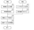
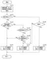
図23は、IoT家電サービスを利用するまでの手順の一例を示すフローチャートである。 FIG. 23 is a flow chart showing an example of the procedure for using the IoT home appliance service.
まず、機器10は、家電量販店などでユーザに購入された後、ユーザ自身または販売者が当該機器10を自宅まで輸送して設置する(S11)。機器10がエアコンなどの大型家電の場合には、設置工事を伴うものもある。一般的な大型家電は外部電源で動作するため、家庭内のコンセントに接続することで通電され、家電機器としての動作を始める。 First, after the
次に、機器10の常時接続の設定が為される(S12)。現在広く利用されているWi-Fi技術では、機器10は、各家庭内のWi-Fiアクセスポイントに接続されることで常時接続が為されてもよい。このためには、Wi-Fiアクセスポイントの名称や、必要に応じて暗号化通信のためのパスワードなどを設定する必要がある。なお、LTEなど通信キャリアのキャリア網に接続される場合には、予め工場出荷までに家電機器の設定を行っておくことで、この常時接続設定は不要である。 Next, the
こうして、常時接続設定が完了すると、機器10は、稼働情報をサーバ20に送信することが可能となる。たとえば、運転状況のログなどの履歴データをサーバ20に送信することが想定される。ただし、セキュリティ上の問題からこの時点ではまだ当該機器10に対してユーザは外部から操作を行うことはできない。 Thus, when the constant connection setting is completed, the
次に、ユーザは、機器10を操作するためのユーザアカウントを作成する(S13)。通常のケースでは、操作機器を用いてWebブラウザで閲覧するIoT家電サービスのホームページ上で、ユーザIDおよびパスワードを設定することでユーザアカウントが作成される。 Next, the user creates a user account for operating the device 10 (S13). In a normal case, a user account is created by setting a user ID and password on the home page of the IoT home appliance service viewed with a web browser using an operation device.
そして、ユーザは、作成されたユーザアカウントを用いて、操作機器でログインする(S14)。操作機器としては、スマートフォン、タブレットの利用を想定するが、スマートスピーカーなどのVPA(Virtual Private Assistant)機器の利用も想定される。 Then, the user uses the created user account to log in with the operation device (S14). As operating devices, smartphones and tablets are assumed to be used, but VPA (Virtual Private Assistant) devices such as smart speakers are also assumed to be used.
こうして、ユーザが操作機器でログインを行った後で、機器10とユーザIDとの紐付けを行う(S15)。この紐付けを行うことによって、以降は当該ユーザのアカウントでログインした操作機器からの操作が可能となる。 In this way, after the user has logged in using the operating device, the
この後で、IoT家電を用いた様々なサービスが利用可能となる(S16)。近年では、設置工事担当者や修理で訪問したサービスマンがWi-Fi設定やユーザアカウントの設定を補佐、代行入力してくれるケースもある。 After this, various services using IoT home appliances become available (S16). In recent years, there have been cases where a person in charge of installation work or a serviceman visiting for repairs assists with the Wi-Fi settings and user account settings and inputs them on behalf of the user.
機器10を用いた様々なサービスとして例えば、冷蔵庫内にカメラが設置されているとすると、外出先からでもスマートフォンでログインしておけば、IoT家電に対応したアプリを用いてカメラで撮影した画像を閲覧することで、冷蔵庫に入れてある食品などを確認することができる。なお、予め紐付けされたユーザアカウントでのみIoT家電の操作ができるため、無関係な第三者から冷蔵庫内の映像を盗み見される心配はない。 As a variety of services using the
ユーザアカウントの紐付けが完了していない状態の機器10は各種サービスを利用できない、つまり機能制限がかかった状態であるので、ユーザにフル機能の提供をするために電源起動時などタイミングでユーザアカウントの紐付けを促す通知を表示するなどの工夫が考えられる。 Various services cannot be used on the
図24は、機器10とユーザとの紐付け手順の第1の例を説明するための図である。図25は、機器10とユーザとの紐付け手順の第1の例を示すフローチャートである。 FIG. 24 is a diagram for explaining a first example of the procedure for associating the
第1の例では、まず、ユーザは、スマートフォンなどの操作機器40にユーザIDおよびパスワードを入力することでログインする(S21)。 In the first example, first, the user logs in by entering a user ID and password into the
次に、ユーザは、操作機器40を用いて、機器10に与えられた機器コードを入力し、機器10は、入力された機器コードをサーバ20に送信する(S22)。 Next, the user uses the
この例では、機器10自身に機器コードが表示される。なお、機器コードは、機器10に表示される代わりに、例えば保証書、取扱説明書などの機器10の付属物に記載されていても良い。また、入力ミスを防止するためにスマートフォンが備えるカメラで機器コード撮影し、スマートフォン自身またはサーバ側で文字認識させてもよい。また、機器コードは、数字などの文字列としなくてもよく、二次元バーコードなどであってもよい。 In this example, the device code is displayed on the
機器10が機器コードをサーバ20に送信すると、サーバ20は、機器コードで指定された機器10に対して通知を行う。なお、機器10のメーカは、工場での設定において機器コードと、通信モジュールによる通信のための通信アドレス情報との対応表を作成しておくことが必要となる。これにより、サーバ20は、対応表を記憶部203に記憶していれば記憶部203に記憶されている対応表を参照すること、そうでなければ外部装置から対応表を取得し、取得された対応表を参照することで、指定された機器コードに対応する通信アドレスを特定し、当該機器10に対して通知を行うことが可能となる。 When the
機器10は、サーバ20からの通知を受信すると、機器10が備える表示部112で通知があった旨を表示する(S23)。例えば、機器10は、表示用のランプを明滅させることによって、通知の受信をユーザに知らせてもよい。 When the
この受信の通知を行った後で、ユーザは、機器10の操作部111に入力を行うことで、ユーザにより入力がされたことを示す情報がサーバ20に送信される(S24)。これにより、サーバ20は、機器IDとユーザIDとを紐付けることで、機器10とユーザとの紐付けを完了する。操作部111は、例えば、入力用のボタンであってもよく、ボタンが押下されることで入力が為されてもよい。 After this notification of reception is given, the user performs input to the
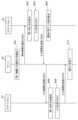
図26は、機器10とユーザとの紐付け手順の第1の例を示すシーケンス図である。 FIG. 26 is a sequence diagram showing a first example of the procedure for associating the
操作機器40は、入力されたユーザIDとパスワードを受け付けて、ユーザIDおよびパスワードをサーバ20に送信する(S31)。これにより、サーバ20は、操作機器40からユーザIDを受信する。ここで、操作機器40は、第1操作機器の一例である。また、ユーザは、第1ユーザの一例であり、ユーザIDは、第1ユーザ識別子の一例である。サーバ20では、予めサーバ20で管理されているユーザ情報に基づいてパスワードが正しいかどうかが確認される。ここで、パスワードが正しくなかった場合には第三者による成りすましの可能性があるため、以降の処理は継続されない。 The
パスワードが正しかった場合、サーバ20は、操作機器40に対してログイン情報を送信する(S32)。ログイン情報とは、例えばセッションを識別するためのIDと、以降の通信で利用する鍵データである。 If the password is correct, the
次に、操作機器40は、図24および図25で示した方法で取得した機器コードをサーバ20に対して送信する(S33)。これにより、サーバ20は、操作機器40から機器コードを受信する。ここで、機器10は、第1機器の一例である。また、機器コードは、機器関連情報の一例である。 Next, the
なお、図24および図25では、機器コードをそのまま送信するとしているが、実際にはログイン情報を用いて処理した結果を送付することが望ましい。処理の方法としては、機器コードだけではなくセッションを識別するためのIDを機器コードに付与した上で、先述した鍵データで暗号化するなどの方法が想定される。また、通信全体をSSLなどの暗号化通信で保護することも好ましい。 In addition, in FIGS. 24 and 25, it is assumed that the device code is sent as it is, but in reality it is desirable to send the result of processing using the login information. As a processing method, not only the device code but also an ID for identifying the session is added to the device code, and then encrypted with the key data described above. It is also preferable to protect the entire communication with encrypted communication such as SSL.
サーバ20は、ユーザIDおよび機器コードを受信することで、ユーザIDおよび機器コードの対応付けの要求を受け付ける。また、サーバ20は、取得された機器コードに基づいて機器10を特定し、特定された機器10にネットワークを介して第4の問い合わせとしての制御信号を送信する。サーバ20は、機器コードと予めサーバ20で管理されている機器情報(つまり、上述した対応表)とに基づいて、機器情報において機器コードに対応付けられている機器10の通信アドレスに変換する。通信アドレスに変換できれば、サーバ20は、当該機器10に対して表示部112での明滅を指示する制御信号を送信する(S34)。 By receiving the user ID and the device code, the
なお、この明滅指示の制御信号については、サーバ20による成りすましを防止するための仕組みが必要である。成りすましの防止ができなければ、擬似サーバを利用することによって、悪意のある第三者のユーザアカウントと機器10とを紐付けることが可能となってしまう。成りすましの防止のためには、例えばサーバ20の公開鍵を予め機器10で保持しておき、サーバ20からの明滅指示は時変要素を加えた上で通知し、全体にサーバ20の秘密鍵による署名を付与することなどが望ましい。 It should be noted that a mechanism for preventing spoofing by the
機器10は、明滅指示を受信すると、表示部112を明滅させる。その後ユーザが操作部111に入力を行えば、機器10は、サーバ20に受け付けた入力を送信する(S35)。つまり、機器10は、第4の問い合わせに対する第4の応答をサーバ20に送信する。 When the
サーバ20は、入力を受信すると、ユーザアカウントと機器10との紐付けを完了し、完了通知を操作機器40に送信する(S36)。つまり、サーバ20は、第4の応答を機器10から受信した場合に、機器IDとユーザIDとを対応付けて記憶部203に記憶する。 Upon receiving the input, the
なお、サーバ20は、入力を待つ期間を定めておくことが望ましい。通常は1分程度とする必要がある。サーバ20は、明滅指示の制御信号を送信してから、カウントを開始し、入力を待つ期間が経過しても入力を受信できない場合、紐付けが失敗した旨の完了通知を操作機器40に送信してもよい。つまり、サーバ20は、所定期間が経過しても第4の応答を受信しない場合に、機器IDとユーザIDとの対応付けを行わない。サーバ20は、第4の問い合わせを送信したタイミングで、カウントを開始し、カウントが所定期間に達しても第4の応答を受信しない場合に、機器IDとユーザIDとの対応付けを行わずに処理を終了する。 In addition, it is desirable that the
操作機器40は、受信した完了通知を表示する。
図27は、機器10とユーザとの紐付け手順の第2の例を示すフローチャートである。 FIG. 27 is a flow chart showing a second example of the procedure for associating the
第2の例では、まず、ユーザは、スマートフォンなどの操作機器40にユーザIDおよびパスワードを入力することでログインし(S41)、ログインした状態で待機させ、ユーザは、機器10の設定ボタンを押す(S42)。 In the second example, first, the user logs in to the
機器10は、設定ボタンが押されるとサーバ20に対し、機器10とユーザアカウントとを紐付けるためのパスワードを要求する。この時、サーバ20は、ワンタイムパスワードまたは時限式のパスワードを発行することが望ましい。そして、機器10は、サーバ20からパスワードを受信し、パスワードを表示部112に表示する(S43)。 When the setting button is pressed, the
ユーザは、表示部112に表示されたパスワードを操作機器40に入力し、操作機器40は、入力されたパスワードをサーバ20に送信する(S44)。この例において、パスワードは、数字などの文字列を例示しているが、二次元バーコードまたはLEDの明滅パターン、モールス信号などの音データ等であってもよい。二次元バーコードまたはLEDの明滅パターンの場合には、操作機器40のカメラを用いて読み取ることにより、パスワードが入力される。モールス信号などの音データである場合には、操作機器40のマイクで収音することにより、パスワードが入力される。 The user enters the password displayed on the
サーバ20は、操作機器40からパスワードを受信すると、紐付け要求をした機器10とパスワードを送ってきたユーザアカウントとの間で紐付けし(S45)、紐付け完了を示す通知を機器10に送信する。 When the password is received from the
機器10は、サーバ20からの紐付け完了の通知を受信すると、機器10が備える表示部112で通知があった旨を表示する(S46)。例えば、機器10は、表示用のランプを明滅させることによって、通知の受信をユーザに知らせてもよい。 When receiving the linking completion notification from the
図28は、機器10とユーザとの紐付け手順の第2の例を示すシーケンス図である。 FIG. 28 is a sequence diagram showing a second example of the procedure for linking the
操作機器40は、入力されたユーザIDとパスワードを受け付けて、ユーザIDおよびパスワードをサーバ20に送信する(S51)。これにより、サーバ20は、操作機器40からユーザIDを受信する。ここで、操作機器40は、第1操作機器の一例である。また、ユーザは、第1ユーザの一例であり、ユーザIDは、第1ユーザ識別子の一例である。サーバ20では、予めサーバ20で管理されているユーザ情報に基づいてパスワードが正しいかどうかが確認される。ここで、パスワードが正しくなかった場合には第三者による成りすましの可能性があるため、以降の処理は継続されない。 The
パスワードが正しかった場合、サーバ20は、操作機器40に対してログイン情報を送信する(S52)。ログイン情報とは、例えばセッションを識別するためのIDと、以降の通信で利用する鍵データである。 If the password is correct, the
次に、機器10は、ユーザからの入力を受け付けると、サーバ20に対してワンタイムパスワードの発行を要求する(S53)。なお、この要求の際に、機器10は、あわせて自身の機器IDをサーバ20に送信する。ここで、機器10は、第1機器の一例である。また、機器IDは、機器関連情報の一例である。また、機器IDは、機器識別子とも言う。なお、サーバ20は、通信の際の機器10のアドレス情報に基づいて、サーバ20で予め管理されている機器情報から、対応する機器IDを取得してもよい。この場合、アドレス情報は、機器関連情報の一例である。 Next, upon receiving the input from the user, the
サーバ20は、ユーザIDおよび機器IDを受信することで、ユーザIDおよび機器コードの対応付けの要求を受け付ける。また、サーバ20は、ワンタイムパスワードの要求に応答して、ワンタイムパスワードを機器10に送信する(S54)。なお、機器10の通信アドレスは、上述した第1の例におけるステップS34と同様の方法を用いることで特定される。ここで送信されるワンタイムパスワードは、第4の問い合わせの一例である。発行されたワンタイムパスワードは、機器10の表示部112で表示される。 By receiving the user ID and the device ID, the
操作機器40は、表示部112に表示されたワンタイムパスワードの入力をユーザから受け付け、入力されたワンタイムパスワードをサーバ20に送信する(S55)。つまり、機器10は、第4の問い合わせに対する第4の応答としてのワンタイムパスワードをサーバ20に送信する。
なお、図28では、ワンタイムパスワードをそのまま送付するとしているが、実際にはログイン情報を用いて処理した結果を送付することが望ましい。処理の方法としては、機器コードだけではなくセッションを識別するためのIDを機器コードに付与した上で、先述した鍵データで暗号化するなどの方法が想定される。また、通信全体をSSLなどの暗号化通信で保護することも好ましい。 In FIG. 28, the one-time password is sent as it is, but in reality it is desirable to send the result of processing using the login information. As a processing method, not only the device code but also an ID for identifying the session is added to the device code, and then encrypted with the key data described above. It is also preferable to protect the entire communication with encrypted communication such as SSL.
サーバ20は、操作機器40から受け取ったワンタイムパスワードが予め発行したワンタイムパスワードと一致しているかを確認し、一致を確認した段階でユーザアカウントと機器IDを紐付ける。つまり、サーバ20は、第4の応答を機器10から受信した場合に、機器IDとユーザIDとを対応付けて記憶部203に記憶する。サーバ20は、紐付けの完了通知を操作機器40に送信する(S56)。 The
なお、サーバ20は、入力を待つ期間を定めておくことが望ましい。通常は1分程度とする必要がある。サーバ20は、ワンタイムパスワードを送信してから、カウントを開始し、入力を待つ期間が経過しても入力を受信できない場合、紐付けが失敗した旨の完了通知を操作機器40に送信してもよい。つまり、サーバ20は、所定期間が経過しても第4の応答を受信しない場合に、機器IDとユーザIDとの対応付けを行わない。サーバ20は、第4の問い合わせを送信したタイミングで、カウントを開始し、カウントが所定期間に達しても第4の応答を受信しない場合に、機器IDとユーザIDとの対応付けを行わずに処理を終了する。 In addition, it is desirable that the
操作機器40は、受信した完了通知を表示する。
このように、ユーザIDと機器IDとの対応付けをユーザが所望する組合せで対応付けることができるため、精度よく機器とユーザとの対応付けを行うことができる。また、機器は、LPWAの基地局30を介して第4の問い合わせを受信できる。 In this way, the user ID and the device ID can be associated in a combination desired by the user, so that the device and the user can be associated with high accuracy. The device can also receive a fourth query via the
以上のように、ユーザIDと機器IDとが対応付けられてサーバ20の記憶部203に記憶されることで、記憶部203には、複数のユーザID毎に、複数の機器IDが対応付けられた対応関係が記憶されることとなる。 As described above, the user IDs and the device IDs are associated with each other and stored in the
次に、複数の機器と複数のユーザとの紐付けの方法について説明する。 Next, a method for associating multiple devices with multiple users will be described.
図29は、複数の機器と複数のユーザとの紐付けの方法の一例の第1の場面を説明するための図である。 FIG. 29 is a diagram for explaining a first scene of an example of a method of associating a plurality of devices with a plurality of users.
ここでは、2台のエアコン11、13、1台の冷蔵庫12、および1台のテレビ14により構成される合計で4台のIoT家電が1つの家庭内に設置されている例が示されている。2台のエアコン11、13は、それぞれ、リビングルームおよび子供部屋に設置されている。エアコン11、13、冷蔵庫12およびテレビ14のそれぞれは、機器10の一例である。つまり、エアコン11、13、冷蔵庫12およびテレビ14のそれぞれは、図示しないが、基地局30とLPWAによって通信接続されている。 Here, an example is shown in which a total of four IoT home appliances, including two
また、この家庭は、父、母、兄および妹から構成される4人家族であり、父と母は各々エアコン11、13、冷蔵庫12およびテレビ14を操作するためのユーザアカウント(ユーザID)を保有しているものとする。ここで、父は、第2ユーザの一例であり、母は、第1ユーザの一例である。ユーザアカウントは、サーバ20が実現するIoT家電制御クラウド上におけるユーザアカウントである。 This family consists of a father, a mother, an older brother, and a younger sister. The father and mother each have a user account (user ID) for operating the
既に述べたように機器10は、ユーザアカウントと紐付けられる前から、その常時接続性を生かして家電の操作ログまたは動作ログをサーバ20へ基地局30を介して送信している。一方で、ユーザは、スマートフォン、VPAなどの操作機器を用いて、機器10の操作を行おうとする場合、機器10とユーザアカウントとの紐付けが必須である。 As already described, the
例えば、図29の例では、父が所有するスマートフォン41上で動作するアプリにおいて、dad@panasonic.comというユーザアカウントでログインし、リビングルームのエアコン11に対して紐付けを既に行っているものとする。つまり、サーバ20で記憶されている対応関係には、dad@panasonic.comというユーザアカウントと、エアコン11の機器IDとが対応付けられている。また、サーバ20で記憶されている対応関係には、ユーザアカウント、及び、操作対象となる機器の機器IDに、さらに、IoT家電制御クラウドへのログインに用いられた操作機器の機器IDが対応付けられていてもよい。つまり、対応関係では、dad@panasonic.comと、エアコン11の機器IDと、スマートフォン41の機器IDとが対応付けられていてもよい。これによって、父は、所有するスマートフォン41を用いてエアコン11を操作することができる。なお、dad@panasonic.comは、第2ユーザIDの一例である。エアコン11は、第1機器の一例であり、エアコン11の機器IDは、第1機器IDの一例である。スマートフォン41は、第2操作機器の一例である。 For example, in the example of FIG. 29, in the application running on the
また、母は、所有するスマートフォン42上で動作するアプリにおいて、mom@panasonic.comというユーザアカウントでログインし、冷蔵庫12に対して紐付けを既に行ったものとする。つまり、サーバ20で記憶されている対応関係には、mom@panasonic.comというユーザアカウントと、冷蔵庫12の機器IDとが対応付けられている。なお、対応関係では、mom@panasonic.comと、冷蔵庫12の機器IDと、スマートフォン42の機器IDとが対応付けられていてもよい。これによって、母は、所有するスマートフォン42を用いて冷蔵庫12を操作することができる。なお、mom@panasonic.comは、第1ユーザIDの一例である。冷蔵庫12は、第2機器の一例であり、冷蔵庫12の機器IDは、第2機器IDの一例である。スマートフォン42は、第1操作機器の一例である。 In addition, my mother uses an application running on her
さらに、この例では、家庭内にVPA43が設置されており、このVPAは、父のユーザアカウントであるdad@panasonic.comでログインされている。VPA43は、子供部屋のエアコン13およびテレビ14に対して紐付けを既に行ったものとする。なお、対応関係では、dad@panasonic.comと、エアコン13およびテレビ14の各機器IDと、スマートフォン41の機器IDとが対応付けられていてもよい。これによって、ユーザは、VPA43を用いて、子供部屋のエアコン13およびテレビ14を操作することができる。なお、VPA43は、一般的に家族共用で利用されるケースが多い。この場合には、兄または妹は、自分のスマートフォンまたはユーザアカウントを持ってはいないものの、VPA43を用いて子供部屋のエアコン13またはテレビ14を操作することができる。 Furthermore, in this example, a
図30は、複数の機器と複数のユーザとの紐付けの方法の一例の第2の場面を説明するための図である。第2の場面は、複数の同一のユーザアカウントを介して複数の操作機器と機器との紐付けが行われる場面である。 FIG. 30 is a diagram for explaining a second scene of an example of a method for associating a plurality of devices with a plurality of users. A second scene is a scene in which a plurality of control devices and devices are linked via a plurality of identical user accounts.
さて、図29では父が所有するdad@panasonic.comというユーザアカウントは、スマートフォン41、VPA43などの複数の操作機器で利用されている。このユーザアカウントを介することによって、明示的には紐付けられていない操作機器とIoT家電とが紐付けられてもよい。 Now, in FIG. 29, dad@panasonic.com owned by my father. com user account is used in a plurality of operating devices such as the
図30では、同一のユーザアカウントを介することにより間接的に紐付けられる操作機器とIoT家電との関係を点線で示している。この例では、父は、父が所有するスマートフォン41を用いることで、サーバ20が記憶している対応関係において明示的に紐付けられているリビングルームのエアコン11に加えて、同一のユーザアカウントで間接的に紐付けられた子供部屋のエアコン13およびテレビ14の操作を許可してもよい。 In FIG. 30 , the dotted line indicates the relationship between the operation device and the IoT home appliance that are indirectly linked via the same user account. In this example, by using the
また、サーバ20は、2台のエアコン11、13、およびテレビ14を同一のdad@panasonic.comというユーザアカウントで紐付けて管理することとなる。これによって、例えば2台のエアコン11、13で部屋を空調するときの温度設定などの設定情報を共有することができる。また、テレビ14の視聴状態に応じてテレビ14が設置されている部屋と同じ部屋に設置されているエアコン11の運転状態を適切に制御することが可能となる。 Also, the
図31は、複数の機器と複数のユーザとの紐付けの方法の一例の第3の場面を説明するための図である。第3の場面は、機器を介してユーザアカウント同士の紐付けが行われる場面である。 FIG. 31 is a diagram for explaining a third scene of an example of a method for associating a plurality of devices with a plurality of users. A third scene is a scene in which user accounts are linked via a device.
さて、さらに図31では、母が所有するスマートフォン42上で動作するアプリにて、リビングルームのエアコン11を母のユーザアカウントmom@panasonic.comに紐付ける操作をサーバ20が受け付けたとする。この場合、母はスマートフォン42を用いて、図24~図27を用いて上述した機器10とユーザとの紐付け手段を行ったものとする。 Further, in FIG. 31, the application running on the
このとき、既にエアコン11には、父のユーザアカウントであるdad@panasonic.comが紐付けられており、同じエアコン11に複数のユーザアカウントが紐付けられたということは、これらの複数のユーザアカウントを所有しているユーザ同士は家族であるという蓋然性が高い。 At this time, the
このため、この場合にサーバ20は、父のユーザアカウントと母のユーザアカウントで紐付けられている機器とを紐付けて、紐付けた結果を対応関係としてさらに記憶部203に記憶させてもよい。同様に、サーバ20は、父のユーザアカウントで紐付けられている機器と母のユーザアカウントとを紐付けて、紐付けた結果を対応関係としてさらに記憶部203に記憶させてもよい。つまり、サーバ20は、記憶部203に記憶されている対応関係において、(i)第1機器IDに、第1ユーザIDとは異なる第2ユーザIDが対応付けられており、かつ、(ii)第1ユーザIDに、複数の機器のうちの第1機器とは異なる第2機器を識別する第2機器IDが対応付けられている場合、第2識別子と第2ユーザIDとを対応付けて記憶部203に記憶させる。これにより、サーバ20は、対応関係を更新する。 Therefore, in this case, the
このように、同一の機器IDに異なるユーザアカウントの紐付けが行われるケースを検知した場合に行われる紐付け処理の一例について次の図32および図33を用いて説明する。 An example of the linking process performed when detecting a case in which different user accounts are linked to the same device ID in this way will be described with reference to FIGS. 32 and 33 below.
図32は、同一の機器IDに異なるユーザアカウントの紐付けが行われる場合に行われる紐付け処理の一例を示すシーケンス図である。図33は、同一の機器IDに異なるユーザアカウントの紐付けが行われる場合に行われる紐付け処理において操作機器への通知を示す情報の一例を示す図である。 FIG. 32 is a sequence diagram illustrating an example of linking processing performed when different user accounts are linked to the same device ID. FIG. 33 is a diagram illustrating an example of information indicating notification to the operation device in the linking process performed when different user accounts are linked to the same device ID.
図32に示すように、まず、サーバ20は、同一機器への紐付けを検出する(S61)。例えば、上述したように、母がスマートフォン42を操作することにより、エアコン11の機器IDと母のユーザアカウントとの紐付けの要求がスマートフォン42により送信される。サーバ20は、当該要求を受信することで、対応関係において、エアコン11の機器IDに紐付けられている他のユーザアカウントがあるか否かを判定する。サーバ20は、他のユーザアカウントがある場合、同一機器への紐付けを検出する。一方で、サーバ20は、他のユーザアカウントが無い場合、エアコン11の機器IDと母のユーザアカウントとの紐付けを行い、この処理を終了する。 As shown in FIG. 32, first, the
サーバ20は、ステップS61の後で、検出結果をスマートフォン42に通知する(S62)。ここで、サーバ20により送信される検出結果には、対応関係においてdad@panasonic.comで識別されるユーザである父が、mom@panasonic.comで識別されるユーザである母の家族であるか否かを確認する第1の問い合わせが含まれる。 The
スマートフォン42は、サーバ20から検出結果を受信すると、図32に示されるように、同一機器への紐付けを検出したことをユーザに通知する画面421を表示する。これにより、ユーザアカウントと紐付けようとした機器に既に他のユーザアカウントが紐づいていたことを検出した旨がユーザに対して通知される。 Upon receiving the detection result from the
次に、スマートフォン42は、サーバ20から受信した検出結果に基づいて、第1の問い合わせを示す画面422を表示する(S63)。これにより、ユーザに、ステップS61において検出された他のユーザアカウントで示されるユーザ(つまり、父)が母の‘家族であるかどうかが確認される。ここでは、家庭内に設置された機器に対する紐付けが行われる場合であるため、画面422において家族であるか否かが確認されるユーザとして、無関係な第三者が表示されることは原則として考えにくい。 Next, the
次に、スマートフォン42は、第1の問い合わせを示す画面422への入力を受け付け(S64)、受け付けた入力結果をサーバ20に送信する(S65)。入力結果は、第1の問い合わせに対する第1の応答を示す。スマートフォン42は、入力結果をサーバ20に送信すると、入力結果としての通知を、サーバ20を介してスマートフォン41に送信したことが完了した旨を示す画面423を表示する(S66)。 Next, the
サーバ20は、ステップS65で送信された入力結果を受信すると、入力結果が、父が母の家族であることが母により承認されたことを示す応答を含む場合、当該入力結果を父のユーザアカウントに対応付けられているスマートフォン41に送信する(S67)。サーバ20は、当該入力結果を、エアコン11の機器IDと母のユーザアカウントとを対応付けることを示す通知として送信する。通知は、母が父の家族であるか否かを父に確認する第2の問い合わせを含んでいてもよい。 When the
スマートフォン41は、サーバ20から受信した通知に基づいて、第2の問い合わせを示す画面411を表示する(S68)。画面411は、アプリが次回に起動されたときに表示されてもよいし、メールまたは通知などのプッシュ式の仕組みを使って表示されてもよい。 The
次に、スマートフォン41は、第2の問い合わせを示す画面411への入力を受け付け(S69)、受け付けた入力結果をサーバ20に送信する(S70)。 Next, the
サーバ20は、ステップS70で送信された入力結果を受信すると、入力結果が、母が父の家族であることが父により承認されたことを示す応答を含む場合、エアコン11の機器IDと母のユーザアカウントとを対応付けて記憶する(S71)。 When the
なお、サーバ20は、ステップS65で受信された入力結果が、父が母の家族であることが母により承認されなかったことを示す応答を含む場合、ステップS71において、エアコン11の機器IDと母のユーザアカウントとの対応付けを行わなくてもよい。例えば、ステップS65で家族でないとの回答が受信された場合には、本例ではサーバ20は、処理を停止してもよい。なお、この場合、サーバ20は、処理を停止するのではなく、積極的に紐付けを解除してもよい。これは、IoT家電が譲渡されたケース、知人が訪問してきた際に誤って、または悪意を持って紐付け操作が行われた場合への対策である。先に紐付けを行ったユーザが解除権を持つとの考え方がもっともシンプルであるが、この方法では譲渡に対応できないため、例えば強制的に紐付けの解除の操作をIoT家電の操作部で受け付けてもよい。このように、第1の問い合わせへの結果である第1の応答に応じて、機器IDとユーザアカウントとを対応付けるため、望ましくない対応付けの要求を受け付けないようにすることができる。 Note that if the input result received in step S65 includes a response indicating that the mother did not approve that the father is a member of the mother's family, the
また、サーバ20は、ステップS70で受信された入力結果が、母が父の家族であることが父により承認されなかったことを示す応答を含む場合、ステップS71において、エアコン11と母のユーザアカウントとの対応付けを行わなくてもよい。例えば、ステップS70で家族でないとの回答が受信された場合には、本例ではサーバ20は、処理を停止してもよい。このように、第2の問い合わせへの結果である第2の応答に応じて、機器IDとユーザアカウントとを対応付けるため、望ましくない対応付けの要求を受け付けないようにすることができる。 Further, if the input result received in step S70 includes a response indicating that the father did not approve that the mother is a family member of the father, the
なお、別の形態としては、家族か否かを問い合わせることなく、無条件に家族として取り扱ってもよい。つまり、第1の問い合わせおよび第2の問い合わせをすることなく、無条件に父と母とが家族であるとして、エアコン11と母のユーザアカウントとの紐付けを行ってもよい。 As another form, the person may be treated unconditionally as a family member without inquiring whether or not the person is a family member. In other words, the
また、家族と問い合わせたとしてNOとの回答があった場合には、当該IoT家電において紐付け元のユーザアカウントとの紐付けを許可しなくてもよい。 Also, if the answer to the question is NO when inquiring about the family, the IoT home appliance does not need to permit the linking with the user account of the linking source.
図34は、複数の機器と複数のユーザとの紐付けの方法の一例の第4の場面を説明するための図である。第4の場面は、機器を介してユーザアカウント同士の紐付けが行われる別の場面である。 FIG. 34 is a diagram for explaining a fourth scene of an example of a method for associating a plurality of devices with a plurality of users. A fourth scene is another scene in which user accounts are linked via a device.
図32で示したシーケンス図において、父のユーザアカウントと母のユーザアカウントが家族同士であると承認された場合、図33で示すように、家庭内の全てのIoT家電が全てのユーザアカウントと相互に紐付けることができる。つまり、エアコン11、13、冷蔵庫12およびテレビ14と、父のユーザアカウントであるdad@panasonic.comおよび母のユーザアカウントであるmom@panasonic.comとを相互に紐付けることができる。 In the sequence diagram shown in FIG. 32, when the father's user account and the mother's user account are approved as family members, as shown in FIG. can be tied to That is, the
このため、ステップS65で受信された入力結果が、父が母の家族であることが母により承認されたことを示す応答を含み、かつ、ステップS70で送信された入力結果が、母が父の家族であることが父により承認されたことを示す応答を含む場合、サーバ20は、冷蔵庫12の機器IDと父のユーザアカウントとの紐付けを行ってもよい。このように、エアコン11の機器IDと母のユーザアカウントとの対応付けの要求を受け付けた場合、サーバ20は、記憶されている対応関係を用いて、冷蔵庫12の機器IDと父のユーザアカウントとを対応付けて記憶する。このため、ユーザと機器との対応付けを効率よく行うことができる。 Therefore, the input result received in step S65 includes a response indicating that the mother approves that the father is a member of the mother's family, and the input result transmitted in step S70 indicates that the mother is the father's family member. If the response indicates that the father has approved the family, the
なお、サーバ20は、ステップS65で受信された入力結果が、父が母の家族であることが母により承認されたことを示す応答を含む場合に、冷蔵庫12の機器IDと父のユーザアカウントとの紐付けを行ってもよい。また、サーバ20は、第1の問い合わせおよび第2の問い合わせをすることなく、無条件に父と母とが家族であるとして、冷蔵庫12の機器IDと父のユーザアカウントとの紐付けを行ってもよい。 If the input result received in step S65 includes a response indicating that the mother approves that the father belongs to the mother's family, the
また、サーバ20は、母のユーザアカウントとリビングのエアコン11の機器IDとを対応付ける要求があった場合に、対応関係において、エアコン11の機器IDには既に父のユーザアカウントが対応付けられており、かつ、父のユーザアカウントにはさらにエアコン13の機器IDおよびテレビ14の機器IDとが対応付けられている。このため、サーバ20は、エアコン13の機器IDおよびテレビ14の機器IDと母のユーザアカウントとの対応付けを記憶してもよい。このため、ユーザと機器との対応付けをさらに効率よく行うことができる。 When the
これにより、図34の破線で示されるように、各機器の機器IDと、各ユーザアカウントとが紐付けられる。 As a result, the device ID of each device and each user account are associated as indicated by the dashed lines in FIG. 34 .
図35は、複数の機器と複数のユーザとの紐付け方法の別の一例を説明するための図である。 FIG. 35 is a diagram for explaining another example of a method of associating multiple devices with multiple users.
図35で示される例では、父が複数のユーザアカウントを持っているケースである。このようなケースは、家庭内に複数メーカのIoT家電が存在し、各メーカが異なるユーザアカウントの体系を管理および運用している場合に発生しうる。ただし、ユーザ観点ではたとえメーカが異なったとしてもIoT家電同士が連携することが好ましいため、メーカ同士が連携することを前提としたケースとなる。なお、別メーカの例以外にも、たとえ同じメーカであったとしても、スマートフォンの買い替えなどによって、既に作成していたユーザアカウントまたはパスワードを失念してしまい、新たに別のユーザアカウントまたはパスワードを設定した場合などにもこのケースが発生しうる。 In the example shown in FIG. 35, the father has multiple user accounts. Such a case can occur when there are IoT home appliances from multiple manufacturers in the home, and each manufacturer manages and operates a different user account system. However, from the user's point of view, it is preferable that IoT home appliances cooperate with each other even if they are made by different manufacturers. In addition to the example of another manufacturer, even if it is the same manufacturer, it is possible to set up a new user account or password after forgetting the user account or password that has already been created due to the purchase of a new smartphone. This case can also occur when
図35で示される例では、子供部屋のエアコン13またはテレビ14が、リビングルームのエアコン11または冷蔵庫12とは別メーカの製品であり、別メーカのユーザアカウントで設定されてしまっているケースである。この場合には、リビングルームのエアコン11を操作するための父のユーザアカウント(dad@panasonic.com)と、子供部屋のエアコン13を操作するための父のユーザアカウント(dad@matsushita.com)とは各々異なる別のユーザアカウントであるため、当面は別人として取り扱われる。 In the example shown in FIG. 35, the
この状態から、図35で太い点線で示した紐付け操作が行われることでIoT家電を介したユーザ紐付けのシーケンスが始まる。つまり、図24~図34で説明した機器とユーザとの紐付けのシーケンスが開始される。ここでは、原則として図32および図33で示したものと同様のシーケンスとなる。例えば、画面422による「家族ですか?」の問い合わせの前に、サーバ20は、例えば、他のユーザアカウントで識別されるユーザが同一人物であるか否かを確認する「同一人物ですか?」という第3の問い合わせを、現在ユーザが操作しているVPA43に送信してもよい。なお、VPA43に問い合わせをする場合には、VPA43は、音声でユーザに問い合わせをし、ユーザからは音声による応答を取得する。このように、ユーザアカウントが異なる場合には、家族であるのか同一人物であるのかの判定がつかないため、第3の問い合わせをユーザにして、ユーザから応答を得ることで異なるユーザアカウントが家族のユーザアカウントであるか同一人物のユーザアカウントであるかの判別を行う。ここで、受信された応答が、同一人物であることが承認されたことを示す場合、異なるユーザアカウントを対応付けて同一人物であるとして記憶する。操作の観点では家族であるか同一人物であるかの区分には大きな差はないが、例えば、家族であるか同一人物であるかの区分をしておくことで、同一人物であるユーザアカウントに対応付けられた機器から得られた情報を、個々のユーザに最適になるように当該機器を制御することに利用することができる。 From this state, the sequence of user tying via the IoT home appliance starts when the tying operation indicated by the thick dotted line in FIG. 35 is performed. That is, the sequence of linking the device and the user described with reference to FIGS. 24 to 34 is started. Here, in principle, the sequence is the same as that shown in FIGS. 32 and 33. FIG. For example, before the inquiry "Are you a family member?" may be sent to the
なお、第1の問い合わせは、第2ユーザが、第1ユーザが属する第1ユーザグループのメンバであるか否かを確認する問い合わせであればよく、第2ユーザが第1ユーザの家族であるか否かを確認する問い合わせでなくてもよい。つまり、第1の応答には、第2ユーザが第1ユーザグループのメンバであることが承認されたこと、または、承認されなかったことを示す応答が含まれる。 The first inquiry may be an inquiry to confirm whether or not the second user is a member of the first user group to which the first user belongs. It does not have to be an inquiry to confirm whether or not. That is, the first response includes a response indicating that the second user has been approved or disapproved to be a member of the first user group.
同様に、第2の問い合わせは、第1ユーザが、第2ユーザが属する第2ユーザグループのメンバであるか否かを確認する問い合わせであればよく、第1ユーザが第2ユーザの家族であるか否かを確認する問い合わせでなくてもよい。つまり、第2の応答には、第1ユーザが第2ユーザグループのメンバであることが承認されたこと、または、承認されなかったことを示す応答が含まれる。 Similarly, the second inquiry may be an inquiry to confirm whether the first user is a member of a second user group to which the second user belongs, and the first user is a family member of the second user. It does not have to be an inquiry to confirm whether or not. That is, the second response includes a response indicating that the first user was or was not approved to be a member of the second user group.
第1ユーザグループのメンバの家族以外の例は、シェアハウスのメンバである。第2ユーザグループのメンバの家族以外の例も、同様に、シェアハウスのメンバである。 Examples of non-family members of the first user group are members of a share house. Examples other than family members of the members of the second user group are also members of the share house.
このように、上述における「母の家族」は、第1ユーザが属する第1ユーザグループのメンバと読み替えることができる。また、「父の家族」は、第2ユーザが属する第2ユーザグループのメンバと読み替えることができる。 Thus, the "mother's family" in the above description can be read as a member of the first user group to which the first user belongs. Also, "father's family" can be read as a member of the second user group to which the second user belongs.
なお、第2ユーザが、第1ユーザグループのメンバであると承認され、かつ、第1ユーザが、第2ユーザグループのメンバであると承認されれば、第1ユーザグループおよび第2ユーザグループは、同一のユーザグループであると見なされる。 Note that if the second user is approved as a member of the first user group and if the first user is approved as a member of the second user group, the first user group and the second user group are , are considered to be the same user group.
次に、機器10の状態予測のうちの、設置場所の移動または使用ユーザが変更された時のイベントを判定方法について説明する。 Next, a method of determining an event when the installation location is moved or the user is changed in the state prediction of the
図36は、「引っ越し」および「譲渡」を判別する処理の一例を示すフローチャートである。 FIG. 36 is a flow chart showing an example of processing for determining "moving" and "transfer".
機器10は、購入された後で他のユーザに譲渡されることが考えられる。特にユーザと機器10との間で紐付けが行われた後で、当該機器10を他のユーザに譲渡した場合には問題が発生する。何も対策を施さない場合、前に利用していたユーザは、譲渡した後であっても、機器10のログを閲覧すること、または、機器10の操作を行うことが可能である。一方で、機器10をリセットするなどしてユーザと機器との紐付けが解除されれば、このような問題は解決される。しかしながら、このような紐付けの解除のための操作は、従来の家電機器では必要ない操作であるため、譲渡を受けたユーザが正しくリセットを行うことができるかは疑わしい。 After being purchased, the
そこで、サーバ20は、IoT家電から受信した稼働情報および位置情報を用いて譲渡されたか否かを判断することが望ましい。譲渡の際には、通常家電機器への通電を一旦切断した上で、別の場所に移動させて新たに利用を開始することが想定される。サーバ20は、稼働情報を用いることでIoT家電の通電状況を確認することが可能であり、また先述した位置情報を用いることで、設置場所が変更されていることも識別可能である。この二つを組み合わせることにより、サーバ20は、機器10が譲渡された可能性を判断することが可能である。 Therefore, it is desirable for the
例えば、サーバ20は、稼働情報および位置情報を用いて、機器10の通電切断と機器10の設置場所が移動したことを検知する(S81)。サーバ20は、例えば、稼働情報の電源状態が切であるかを判定することで機器10が通電切断であるかを判定することができる。また、サーバ20は、位置情報が前回の位置情報から変化した場合に、機器10の設置場所が移動したことを検知することができる。 For example, the
ただし、これだけではユーザが変らずに住所だけが変わった、つまり引っ越したのか、譲渡されたのかは判断できない。そこで、表示部を有する機器であれば、表示部に、紐付けの変更が必要かどうかの問い合わせ表示させることで、ユーザに問い合わせてもよい。 However, it cannot be determined from this alone that the user has not changed but only the address has changed, that is, whether the user has moved or been transferred. Therefore, if the device has a display unit, the inquiry may be made to the user by displaying an inquiry on the display unit as to whether or not it is necessary to change the association.
つまり、サーバ20は、機器10が表示部を有しているか否かを判定する(S82)。サーバ20は、機器10の情報を参照することで当該機器10が表示部を有しているか否かを判定してもよいし、稼働情報に機器10が表示部を有しているか否かの情報が含まれていれば、稼働情報に基づいて判定してもよい。 That is, the
表示部を有していない場合(S82でNo)、いったん安全のためにユーザと機器との紐付けを保留とする(S83)。その上で、サーバ20は、紐付けを行ったスマートフォンなどの操作機器に、「譲渡」であるのか「引越」であるのかを確認するメッセージを送信することでユーザに「譲渡」であるのか「引越」であるのかを問い合わせる(S84)。この問い合わせで「引越」であることが確認できれば、保留状態を解除して、ユーザと機器10との紐付けを維持する(S85)。反対に「譲渡」であることが確認できれば、紐付けを解除する(S86)。 If the device does not have a display unit (No in S82), the connection between the user and the device is once suspended for safety (S83). After that, the
表示部を有している場合(S82でYes)、表示部を用いて上記問い合わせを行う(S87)。この問い合わせで「引越」であることが確認できれば、保留状態を解除して、ユーザと機器10との紐付けを維持する(S88)。反対に「譲渡」であることが確認できれば、紐付けを解除する(S89)。 If the device has a display unit (Yes in S82), the above inquiry is made using the display unit (S87). If it can be confirmed by this inquiry that it is "moving", the pending state is canceled and the association between the user and the
このように、譲渡を受けたユーザは、紐付けが解除されることで適切にリセット操作を行うことが可能である。逆に、ユーザが変わらずに住所だけが変わったのであれば、サーバ20は、紐付けの変更が不要であると判断することができ、ユーザは引き続きこれまでどおりに機器10を利用することが可能である。 In this way, the user who received the transfer can appropriately perform the reset operation by canceling the link. Conversely, if the user has not changed but only the address has changed, the
以上のように、制御部202は、第2のタイミングの後の第3のタイミングで受信された第3固有情報が第2固有情報と異なる場合、第3固有情報を送信した機器10が移動したと判断し、機器10のユーザが他のユーザに変更されたか否かの問い合わせを、機器10またはユーザが所有するスマートフォンなどの端末に、通信部201を用いて送信してもよい。なお、第3のタイミングとは、ステップS81の検知のタイミングに対応する。 As described above, when the third unique information received at the third timing after the second timing is different from the second unique information, the
制御部202は、問い合わせを送信した後に、機器10または端末から受信した問い合わせに対する回答が、機器10のユーザが他のユーザに変更されたことを示す場合、第3のタイミング以降の第3期間において受信された複数の第3稼働情報を、複数の第1稼働情報および複数の第2稼働情報とは分けて管理する。制御部202は、具体的には、複数の第3稼働情報を第1識別子および第2識別子とは異なる第3識別子で対応付けて記憶部203に記憶することで、複数の第3稼働情報を、複数の第1稼働情報および複数の第2稼働情報とは分けて管理する。このため、機器10の譲渡が為されたか否かを効果的に判定することができる。また、機器10の譲渡が為された場合に、譲渡前のユーザによる稼働情報とは分けて管理するため、譲渡後のユーザに適した機器10の状態を判定することができる。 If the response to the inquiry received from the
一方で、制御部202は、問い合わせを送信した後に、機器10または端末から受信した問い合わせに対する回答が、機器10のユーザが他のユーザに変更されていないことを示す場合、第3のタイミング以降の第3期間において受信された複数の第3稼働情報を複数の第2稼働情報と共に管理する。制御部202は、具体的には、複数の第3稼働情報を第2識別子と対応付けて記憶部203に記憶する。このため、例えば機器10の譲渡が為されずに機器10が移動した場合には、ユーザを変更せずに機器10の管理を行うことができる。 On the other hand, if the response to the inquiry received from the
図37は、「引っ越し」および「譲渡」を判別する処理の他の一例について説明するための図である。図38は、「引っ越し」および「譲渡」を判別する処理の他の一例を示すフローチャートである。 FIG. 37 is a diagram for explaining another example of the process of determining "move" and "transfer". FIG. 38 is a flow chart showing another example of the process of determining "move" and "transfer".
引っ越しと譲渡を区別する方法として、先述の通電切断と、設置場所の移動検知に加え、他の情報を組み合わせることで家電機器が譲渡されたのか引っ越しなのかの可能性をより正確に判定してもよい。図37では、時刻T1で同時に、複数の機器(機器Aおよび機器B)が同時に移動した場合の位置情報の例が示されている。このように同時に複数の機器が移動した場合は、引っ越しが行われたと考えられる。このため、ユーザが所有している複数の機器の位置情報を連動させることで判定精度を上げることができる。例えば、ユーザの所有する冷蔵庫、洗濯機、エアコンなどが同じタイミングで位置変更された場合は高確率で引っ越しの可能性が高く、洗濯機だけ変更されていた場合は引っ越しではない可能性が高くなる。 As a method to distinguish between moving and transferring, in addition to the above-mentioned disconnection of power and detection of movement of the installation location, by combining other information, it is possible to more accurately determine the possibility of whether the home appliance has been transferred or moved. good too. FIG. 37 shows an example of position information when a plurality of devices (device A and device B) move simultaneously at time T1. When a plurality of devices are moved at the same time in this way, it is considered that a move has been made. Therefore, by linking the position information of a plurality of devices owned by the user, the determination accuracy can be improved. For example, if the location of a user's refrigerator, washing machine, air conditioner, etc. is changed at the same time, there is a high probability that the user will move. .
この場合、サーバ20は、稼働情報および位置情報に基づいて、通電切断と設置場所の移動を検知する(S91)。 In this case, the
次に、サーバ20は、連動して場所を移動した機器が複数あるか否かを判定する(S92)。つまり、サーバ20は、第1の場所から第2の場所に移動した機器が複数あるか否かを判定する。 Next, the
サーバ20は、連動して場所を移動した機器が複数あると判定した場合(S92でYes)、引っ越しの可能性が高いと判定する(S93)。 When the
サーバ20は、連動して場所を移動した機器が複数ないと判定した場合(S92でNo)、つまり、移動した機器が1台である場合、譲渡の可能性が高いと判定する(S94)。 If the
このように、制御部202は、時刻T1よりも前の第2のタイミングで複数の機器10から受信された複数の第2固有情報が互いに同じであり、かつ、第2のタイミングの後の時刻T1よりも後の第3のタイミングで複数の機器から受信された複数の第3固有情報が互いに同じであり、かつ、第2固有情報と第3固有情報とが異なる場合、第3のタイミング以降の第3期間において受信された複数の第3稼働情報を複数の第2稼働情報と共に管理してもよい。このため、複数の機器が移動した場合には、ユーザが変更されていないと見なして、機器の管理を行うことができる。 In this way, the
図39は、「引っ越し」および「譲渡」を判別する処理の他の一例について説明するための図である。図40は、「引っ越し」および「譲渡」を判別する処理の他の一例を示すフローチャートである。 FIG. 39 is a diagram for explaining another example of the process of determining "move" and "transfer". FIG. 40 is a flow chart showing another example of processing for determining "moving" and "transfer".
サーバ20は、先述の通電切断と、設置場所の移動を検知することに加え、日毎の稼働回数情報を併せて用いることで、「引っ越し」か「譲渡」かの判定を行っても良い。これにより、判定精度を改善することができる。 The
図39では、位置情報が変化しているが、稼働回数のパターンに変化が少ない。このように、サーバ20は、位置情報が変化してもいても、位置情報が変化する前の期間と、位置情報が変化する後の期間における単位時間当たりの稼働回数の変化のパターンが所定の相関度を満たす場合(つまり類似する場合)、引っ越しの可能性が高いと判断してもよい。 In FIG. 39, the position information has changed, but the pattern of the number of times of operation has little change. In this way, even if the position information changes, the
この場合のサーバ20の処理では、図40に示されるように、図38の処理と比較してステップS92の代わりに、ステップS102を行っている点が異なる。ステップS101、S103、S104の処理は、それぞれ、ステップS91、S93、S94の処理と同様である。 The processing of the
ステップS102では、サーバ20は、利用頻度が変化したか否かを判定している。利用頻度が変化したか否かは、上述したように、稼働回数の変化のパターンが所定の相関度を満たすか否かを判定することで判定している。 In step S102, the
図39に示されるように、日毎の稼働回数が変化するということは家電機器を使う人が異なる可能性が高く、「譲渡」された可能性がより高くなる。逆に日毎の稼働回数が変化しないということはこれまでと利用頻度が変わっていないので同一人物が他の場所で使っている「引っ越し」と考えられる。ただし、この判定方法はシェーバーやドライヤーのように外出先に持ち運んで使う家電機器にそのまま適応することはできない。 As shown in FIG. 39, the fact that the daily number of times of operation changes means that there is a high possibility that the user of the home appliance is different, and that the home appliance has been "transferred". On the other hand, if the number of operations per day does not change, it can be considered that the same person is using it in another place because the frequency of use has not changed. However, this determination method cannot be applied as it is to household appliances such as shavers and hair dryers that are carried and used outside.
図41は、「引っ越し」が予想されるケースの例外について説明するための図である。図42は、機器の種別に応じてカテゴリ分けした表である。 FIG. 41 is a diagram for explaining exceptions to cases in which "moving" is expected. FIG. 42 is a table categorized according to the type of equipment.
上述のように、機器10の位置情報が変化したことで、引っ越しか譲渡かを判定することができるが、外出先で持ち運び使う小型の機器においては位置情報が変更されていたとしても外出先で利用しているだけのケースがある。つまり、位置情報が変化されたことがサーバ20によって検知されても、引っ越しでも譲渡でもない場合がある。例えば、図41に示されるように、持ち運びが想定されるシェーバーやドライヤーなどの小型家電は、ユーザにより持ち運びされると位置が変化することになる。この場合、ユーザは、元の家に帰ってくることが想定される。このため、サーバ20は、元の位置に戻ったことを検知することで、引っ越しも譲渡も行われずにユーザに継続して利用されていると判断することができる。つまりこの場合、サーバ20は、ユーザと機器との紐付けを維持したままとする。 As described above, it is possible to determine whether to move or to transfer the
このように、日常生活の中で基本的に通電切断されない冷蔵庫や洗濯機などの大型家電と宅外への持ち運びが想定されるシェーバーやドライヤーなどの小型家電では、引っ越しと判定する際の影響度を変更することで、より判定精度を高めることができる。なお、図42に示されるように、機器の大きさや、季節によって使用される機器などに応じて、複数のカテゴリに分類し、サーバ20は、これらのカテゴリの特徴に応じて機器の状態の判断を変更してもよい。 In this way, large home appliances such as refrigerators and washing machines, which basically do not turn on and off in daily life, and small home appliances such as shavers and dryers, which are expected to be carried outside the home, are affected by the degree of impact when determining moving. By changing the , it is possible to further improve the determination accuracy. As shown in FIG. 42, the equipment is classified into a plurality of categories according to the size of the equipment and the equipment used depending on the season. may be changed.
次に、機器10の状態予測のうち、機器10が「譲渡・転売・盗難」が予測されるケースについて説明する。 Next, among the state predictions of the
図43は、機器10が「譲渡・転売・盗難」の予測ケースのグラフを示す図である。 FIG. 43 is a diagram showing a graph of prediction cases where the
図43に示されるように、機器10の位置が変化し、かつ、稼働回数のパターンも大きく変化した場合、機器10のユーザが変更したと予測される。このため、サーバ20は、「譲渡・転売・盗難」が発生したと予測する。これにより、サーバ20は、機器10上のLED/ディスプレイ等に、確認を促す通知または警告の通知をするサービスを行うことが可能である。また、ユーザ変更前のアカウント情報が紐付いた状態で残っている場合は該当ユーザに対してメールなどで通知を行い、アカウント情報の紐付け解除を促す。 As shown in FIG. 43, when the position of the
一度、ユーザと機器との紐付けが行われた後で紐付け解除を行った場合、当該機器から過去ユーザのログなどを参照できることは管理上望ましくない。参照できるログは、ユーザと紐付く範囲のログに限定されるべきだが、当該機器の耐用年数、耐用使用回数を超過していることなどのユーザの安全に関わる情報は、家電機器を安全にお使いいただくためにもこれらの情報を伝えた方が良いケースもある。こういった観点を踏まえ、サーバ上では当該機器の初回の使用時から現在までの累計情報をユーザが利用したログとは別途管理しておくことが有用である。または、累計情報に対して、どの期間がユーザと紐付いていたのかを管理することで実現可能となる。 Once the user and the device are linked and then the link is released, it is undesirable from the management point of view to be able to refer to the log of the past user from the device. The logs that can be viewed should be limited to those that are associated with the user, but information related to the user's safety, such as the service life of the device and the number of times the device has been used, should be used safely. In some cases, it is better to convey this information so that you can use it. Based on this point of view, it is useful to manage on the server the accumulated information from the first use of the device to the present separately from the user's usage log. Alternatively, it can be realized by managing which period is associated with the user with respect to the cumulative information.
家電機器に紐付く累計情報は、量販店の店頭で展示していた機器を販売するケースや転売などの再販売のケースで参照できるようにするなどの使い方も考えられる。 Cumulative information linked to home appliances can also be used for referencing in the case of selling a device exhibited at a mass retailer or in the case of resale such as resale.
次に、機器10の状態予測において機器10が盗難された際の対策機能について説明する。 Next, a countermeasure function when the
図44は、機器10が盗難された際の対策を実行する処理のフローチャートである。 FIG. 44 is a flowchart of processing for executing countermeasures when the
機器10が盗難された場合、ユーザが自身のユーザアカウントと紐付く機器10を他ユーザが使用できないようにロックできる機能を持たせることが望ましい。具体的には、盗難された機器10に対して、紐付けを行ったスマートフォンなどの操作機器40を用いて、操作機器から盗難された機器10をロックさせる命令を送る機能である。この機能を持つことで盗難により不正に機器10を入手したユーザが機器10を利用することや、不正なユーザに過去のログが閲覧されることを防ぐことが可能となる。 If the
まず、サーバ20は、機器10が送信する位置情報、稼働状態などの情報から「盗難」の疑いがあることを検知する(S111)。 First, the
ユーザが気づいていれば、ステップS115に進み、ユーザが気づいていなければステップS113に進む。なお、ステップS112では、ステップS111の後で、所定期間経過するまでにユーザの操作機器40からステップS115における操作機器でのロックボタンが押されたことを示す情報を受信したか否かを判定する。これにより、所定期間経過してもロックボタンが押されていない場合には、ステップS113に進む。 If the user has noticed, the process proceeds to step S115, and if the user has not noticed, the process proceeds to step S113. In step S112, after step S111, it is determined whether or not information indicating that the lock button on the operation device in step S115 has been pressed has been received from the user's
ステップS113において、サーバ20は、機器10に紐付くユーザアカウントに対してユーザの操作機器40に機器10が盗難されていないかを問い合わせる(S114)。この機能により、ユーザが盗難されたことに気づいていない状態であっても、家電機器から「ご自宅にありますか?」、「手元にありますか?」などのメッセージが操作機器40に送られることでユーザは盗難されたことに気づくことが可能となる。 In step S113, the
サーバ20は、ステップS114において盗難の入力を操作機器40から受信するとステップS115に進む。なお、この場合、盗難の入力がされたときにステップS115のロックボタンが押されたと見なしてもよい。 When the
ステップS115において、ロックボタンが押されると、機器10がロックされる。このように、機器10をロックさせる機能を使って家電機器をロックすることで不正利用をやめさせることができる。 In step S115, when the lock button is pushed, the
ステップS114において盗難ではないことを示す入力を操作機器40から受信すると、この処理を終了する。 When an input indicating that the item is not stolen is received from the
次に、一旦ロックされた家電機器のロックを解除することが考える。家電機器側だけでロックを解除できてしまうと不正利用を防ぐことができないため、紐付くユーザアカウントにロック解除の確認を送信する機能が必要となる。しかし、ユーザがこの機能を悪用し、ユーザアカウント紐付けした状態で転売し、転売後にロックするなどのケースが考えられるため製造メーカにロック解除用の連絡窓口を設ける必要がある。製造メーカは連絡を受けた家電機器に紐付くユーザアカウントを持つユーザに対して連絡を取り、ロック解除の可否を判断する。 Next, consider unlocking the home appliance that has been locked once. Unauthorized use cannot be prevented if the lock can be unlocked only on the home appliance side, so a function to send unlock confirmation to the associated user account is required. However, it is possible that the user abuses this function, resells the device while it is linked to the user account, and then locks the device after the resale. Therefore, it is necessary to provide the manufacturer with a contact point for unlocking. The manufacturer contacts the user who has a user account associated with the contacted home appliance, and determines whether or not the lock can be unlocked.
盗難対策機能を実現する上で、通信モジュールを用いてクラウドと通信可能なことが前提となる。そのため、盗難の際にこの通信モジュールを取り外してから家電機器を運び出すケースが考えられる。この対策として家電機器は通信モジュールが取り外された状態では常にロックするようにすることが有用である。 In order to realize the anti-theft function, it is a prerequisite that communication with the cloud is possible using a communication module. Therefore, it is conceivable that, in the event of theft, the home appliance may be carried out after the communication module is removed. As a countermeasure, it is useful to always lock the home appliance when the communication module is removed.
このように、制御部202は、第2のタイミングの後の第3のタイミングで受信された第3固有情報が第2固有情報と異なる場合、機器10が移動したと判断し、機器10が盗難されたか否かの問い合わせを、通信部201を用いて、ユーザが所有する端末に送信してもよい。次に、制御部202は、問い合わせを送信した後に、端末から受信した問い合わせに対する回答が、機器10が盗難されたことを示す場合、機器10を使用できないようにロックする制御信号を、通信部201を用いて送信してもよい。この場合、機器10は、制御信号を受信すると、当該機器10を使用できないようにロックしてもよい。このため、機器10が盗難された場合に、他のユーザが機器10を使用できないようにロックすることができる。 In this way, when the third unique information received at the third timing after the second timing is different from the second unique information, the
ここで、機器10を使用できないようにロックするとは、具体的には、機器10が操作部111からのユーザの入力を受け付けない状態となることである。例えば、機器10は、機器10の電源をオフにして、かつ、その後に機器10が操作部111からのユーザの入力を受け付けない状態となってもよい。また、機器10が冷蔵庫、洗濯機、電子レンジ、炊飯器など開閉する扉を有する機器の場合、扉が開かないようにロックされてもよい。 Here, locking the
次に、機器10の状態予測において、複数情報を利用した「引っ越し」および「譲渡」の判別について説明する。 Next, determination of “move” and “transfer” using multiple pieces of information in predicting the state of the
図45は、機器10の移動を検知した際のユーザと機器10との紐付け処理の一例を示すフローチャートである。 FIG. 45 is a flowchart showing an example of processing for associating the user with the
これまで示してきたいくつの判定方法を組み合わせ、「引っ越し」と「譲渡」の判別をするフローの例を示す。 An example of the flow for determining "move" and "transfer" by combining several determination methods shown so far will be shown.
サーバ20は、通電切断、及び、設置場所の移動を検知する(S121)。 The
サーバ20は、機器10に表示部があるか否かを判定する(S122)。 The
サーバ20は、機器10に表示部がない場合(S122でNo)、複数機器が同時に移動したか否かを判定する(S123)。 If the
サーバ20は、複数同時に移動していない場合(S123でNo)、ユーザと機器10との紐付けを保留する(S124)。 If the
ステップS123において、サーバ20は、複数機器が同時に移動した場合(S123でYes)、移動した複数機器が小型家電のみか否かを判定する(S125)。 In step S123, if multiple devices have moved at the same time (Yes in S123), the
サーバ20は、移動した複数機器が小型家電のみである場合(S125でYes)、複数機器が数日で元の設置場所に戻るか否かを判定する(S126)。 When the plurality of devices that have moved are only small home appliances (Yes in S125), the
サーバ20は、複数機器が数日で元の設置場所に戻った場合(S126でYes)、または、ステップS125でNoと判定された場合、ユーザと複数機器との紐付けを維持する(S127)。 If the multiple devices return to their original installation locations in a few days (Yes in S126), or if No in step S125, the
サーバ20は、複数機器が数日で元の設置場所に戻らない場合(S126でYes)、ステップS124に進む。 If the multiple devices do not return to their original installation locations within a few days (Yes in S126), the
ステップS122において、サーバ20は、機器10に表示部があると判定した場合(S122でYes)、譲渡であるか否かをユーザの操作機器40に問い合わせる(S128)。 In step S122, when the
サーバ20は、操作機器40から譲渡であるとの回答を受信した場合(S128でYes)、ユーザと機器との紐付けを解除する。 When the
サーバ20は、操作機器40から譲渡でないとの回答を受信した場合(S128でNo)、ステップS127に進む。 When the
この例では表示部がなく、ユーザに確認が取りにくい構成であっても、引っ越しとほぼ断定できる場合にはユーザと機器10との紐付け状態を保留状態にせず、継続利用できるように判定フローが構築されている。 In this example, even if there is no display unit and the configuration is difficult for the user to confirm, if it can be almost determined that the user has moved, the connection state between the user and the
図46は、機器10の移動を検知した際のユーザと機器10の紐付け処理の他の一例を示すフローチャートである。 FIG. 46 is a flow chart showing another example of processing for associating the user with the
前述の例とは逆に、疑わしい状況を極力紐付け保留にし、利用者の確認を常に要求することでセキュリティを担保する考え方もある。この場合、複数の家電機器を利用している場合一つ一つ確認処理を行うのは煩わしいので、一つ確認した段階でIoT機器間通信しで結果を共有できる構成が望ましい。 Contrary to the previous example, there is also a way of thinking that ensures security by suspending the linking of suspicious situations as much as possible and always requesting confirmation from the user. In this case, when a plurality of home appliances are used, it is troublesome to perform confirmation processing one by one, so it is desirable to have a configuration in which the result can be shared by communicating between IoT devices at the stage of confirming one.
この場合、サーバ20は、通電切断、及び、設置場所の移動を検知する(S131)。 In this case, the
サーバ20は、ユーザと機器10との紐付けを保留する(S132)。 The
サーバ20は、譲渡であるか否かをユーザの操作機器40に問い合わせる(S133)。 The
サーバ20は、操作機器40から譲渡であるとの回答を受信した場合(S133でYes)、ユーザと機器との紐付けを解除する。 When the
サーバ20は、操作機器40から譲渡でないとの回答を受信した場合(S133でNo)、ユーザと機器との紐付けを維持する(S135)。 When the
次に、機器10の状態予測において、ユーザの「家族構成変更」が為されたと予測されるケースについて説明する。 Next, a case in which it is predicted that the user's "family structure change" has been made in the state prediction of the
図47は、ユーザの「家族構成変更」が為されたと予測されるケースのグラフを示す図である。 FIG. 47 is a diagram showing a graph of cases in which it is predicted that the user's "family structure change" has been made.
図47に示されるように、機器10の所在位置が変わらないが、稼働回数のパターンが大きく変化している。この場合が、「家族構成変更」したと予測されるケースである。ユーザは、結婚や両親と同居などの変化があった可能性が考えられ、家電上のLED/ディスプレイ等に、それに見合った商品広告を表示するなどのサービスが可能である。 As shown in FIG. 47, the location of the
次に、機器の状態予測において、機器10が「故障」または「廃棄」と予測されるケースについて説明する。 Next, a case will be described where the
図48は、機器10が「故障」したと予測されるケースのグラフを示す図である。図49は、機器10が「廃棄」されたと予測されるケースのグラフを示す図である。 FIG. 48 is a diagram showing a graph of a case where it is predicted that the
図48および図49に示されるように、サーバ20は、一定期間以上、稼働情報および位置情報を受信していない場合、「故障」または「廃棄」が発生したと予測する。また、サーバ20は、機器10が通信モジュール用バッテリを内蔵する場合において、当該機器10の所在位置が変わってから、稼働回数がゼロとなり一定期間以上データ送信が無い場合、「廃棄」されたと予測してもよい。 As shown in FIGS. 48 and 49, the
他にも、サーバ20は、通信モジュール用バッテリを内蔵する場合は通信が途絶した場所が特定範囲(焼却場やリサイクルセンター)であった場合には、ほぼ確実に「廃棄」と判断できる。該当家電機器がリコール対象だった場合には「廃棄」と判定した段階でリコール対象の管理リストから除外してもよい。仮に「廃棄」が誤判定で、家電機器が再度動き始めた場合には、通信が再開しているはずなので改めてリコール通知を送ることで、対応することができる。このため誤判定になるリスクは少ないと考えられる。 In addition, when the
このように、サーバ20は、第2のタイミングの後の第4のタイミングから所定期間後となっても稼働情報を受信しない場合、第4のタイミングまでに受信された複数の稼働情報の管理状態を非管理状態に変更してもよい。 In this way, if the
また、制御部202は、第2のタイミングの後の第4のタイミングから所定期間後となっても、通信部201が稼働情報を受信せず、かつ、第4のタイミングで受信された第4固有情報が予め保持している固有情報リストに含まれる複数の固有情報のいずれか1つと同じである場合、第4のタイミングまでに受信された複数の稼働情報の管理状態を非管理状態に変更してもよい。 Further, the
このように、サーバ20は、機器10が故障または廃棄と判定した場合、当該機器10の管理をしないため、管理にかかる処理負荷を低減することができる。 In this way, when the
以上のように、本開示における技術の例示として、実施の形態を説明した。そのために、添付図面および詳細な説明を提供した。 As described above, the embodiment has been described as an example of the technique of the present disclosure. To that end, the accompanying drawings and detailed description have been provided.
したがって、添付図面および詳細な説明に記載された構成要素の中には、課題解決のために必須な構成要素だけでなく、上記実装を例示するために、課題解決のためには必須でない構成要素も含まれ得る。そのため、それらの必須ではない構成要素が添付図面や詳細な説明に記載されていることをもって、直ちに、それらの必須ではない構成要素が必須であるとの認定をするべきではない。 Therefore, among the components described in the attached drawings and detailed description, there are not only components essential for solving the problem, but also components not essential for solving the problem in order to exemplify the above implementation. can also be included. Therefore, it should not be immediately recognized that those non-essential components are essential just because they are described in the attached drawings and detailed description.
また、上述の実施の形態は、本開示における技術を例示するためのものであるから、請求の範囲またはその均等の範囲において種々の変更、置き換え、付加、省略などを行うことができる。 In addition, the above-described embodiments are intended to illustrate the technology of the present disclosure, and various modifications, replacements, additions, omissions, etc. can be made within the scope of the claims or equivalents thereof.
本開示は、機器の管理を効率よく行うことができる機器管理システム、機器管理方法などとして有用である。 INDUSTRIAL APPLICABILITY The present disclosure is useful as a device management system, a device management method, and the like that can efficiently manage devices.
1 機器管理システム
10 機器
11、13 エアコン
12 冷蔵庫
14 テレビ
20 サーバ
30 基地局
40 操作機器
41、42 スマートフォン
43 VPA
101 通信モジュール
102 保持部
104 制御部
107 機能モジュール
108 保持部
109 電源部
110 バッテリ
111 操作部
112 表示部
201 通信部
202 制御部
203 記憶部
411、421~423 画面1
101
Claims (13)
Translated fromJapanese前記複数の機器のうちの第1機器を識別する第1機器識別子と前記第1ユーザ識別子との対応付けの要求を前記第1操作機器から受け付ける受け付けステップと、
記憶装置に記憶されている対応関係であって、機器を識別する機器識別子と、ユーザを識別するユーザ識別子とが対応付けられている対応関係において、(i)前記第1機器識別子に、前記第1ユーザ識別子とは異なる第2ユーザ識別子が対応付けられており、かつ、(ii)前記第1ユーザ識別子に、前記複数の機器のうちの前記第1機器とは異なる第2機器を識別する第2機器識別子が対応付けられている場合、前記第2機器識別子と前記第2ユーザ識別子とを対応付けて記憶する記憶ステップと、を含む
機器管理方法。A device management method performed in a server connected for communication via a network to a plurality of devices and a first operation device associated with a first user identifier that identifies a first user, comprising:
a receiving step of receiving, from the first manipulation device, a request for associating a first device identifier that identifies the first device among the plurality of devices with the first user identifier;
In the correspondence relationship stored in the storage device in which a device identifier for identifying a device and a user identifier for identifying a user are associated, (i) the first device identifier is associated with the second (ii) a second user identifier different from the first user identifier is associated with the first user identifier; a storage step of associating and storing the second device identifier and the second user identifier when two device identifiers are associated with each other.
前記対応関係において、前記第1機器識別子に、前記第1ユーザ識別子とは異なる第2ユーザ識別子が対応付けられている場合、前記第2ユーザ識別子で識別される第2ユーザが、前記第1ユーザが属する第1ユーザグループのメンバであるか否かを確認する第1の問い合わせを前記第1操作機器に送信し、
送信された前記第1の問い合わせに対する第1の応答を受信し、
受信された前記第1の応答が、前記第2ユーザが前記第1ユーザグループのメンバであることが承認されたことを示す応答を含む場合、前記第1機器識別子と前記第1ユーザ識別子とを対応付けて記憶する
請求項1に記載の機器管理方法。In the storing step,
In the correspondence relationship, when the first device identifier is associated with a second user identifier different from the first user identifier, the second user identified by the second user identifier is the first user is a member of a first user group to which the first operation device belongs;
receiving a first response to the transmitted first query;
if the first response received includes a response indicating that the second user has been approved to be a member of the first user group, combining the first device identifier and the first user identifier; 2. The device management method according to claim 1, wherein the device management method is stored in association with each other.
受信された前記第1の応答が、前記第2ユーザが前記第1ユーザグループのメンバであることが承認されなかったことを示す応答を含む場合、前記第1機器識別子と前記第1ユーザ識別子との対応付けと、前記第2機器識別子と前記第2ユーザ識別子との対応付けをしない
請求項2に記載の機器管理方法。In the storing step,
the first device identifier and the first user identifier if the first response received includes a response indicating that the second user has not been approved to be a member of the first user group; and the second device identifier and the second user identifier are not associated.
受信された前記第1の応答が、前記第2ユーザが前記第1ユーザグループのメンバであることが承認されたことを示す応答を含む場合、前記第1ユーザが、前記第2ユーザが属する第2ユーザグループのメンバであるか否かを確認する第2の問い合わせを送信し、
送信された前記第2の問い合わせに対する第2の応答を受信し、
受信された前記第2の応答が、前記第1ユーザが、前記第2ユーザグループのメンバであることが承認されたことを示す応答を含む場合、前記第1機器識別子と前記第1ユーザ識別子とを対応付けて記憶する
請求項2または3に記載の機器管理方法。The storing step further comprises:
If the first response received includes a response indicating that the second user has been approved to be a member of the first user group, the first user is 2 send a second query to see if it is a member of a user group;
receiving a second response to the sent second query;
if the second response received includes a response indicating that the first user has been approved to be a member of the second user group, the first device identifier and the first user identifier; 4. The device management method according to claim 2 or 3, wherein the device management method is stored in association with .
受信された前記第2の応答が、前記第1ユーザが前記第2ユーザグループのメンバであることが承認されなかったことを示す応答を含む場合、前記第1機器識別子と前記第1ユーザ識別子との対応付けと、前記第2機器識別子と前記第2ユーザ識別子との対応付けをしない
請求項4に記載の機器管理方法。In the storing step,
if the second response received includes a response indicating that the first user has not been approved to be a member of the second user group, the first device identifier and the first user identifier; and the second device identifier and the second user identifier are not associated.
前記対応関係において、前記第1機器識別子に、前記第1ユーザ識別子とは異なる第2ユーザ識別子が対応付けられている場合、前記第2ユーザ識別子で識別される第2ユーザが前記第1ユーザと同一人物であるか否かを確認する第3の問い合わせを前記第1操作機器に送信し、
送信された前記第3の問い合わせに対する第3の応答を受信し、
受信された前記第3の応答が、前記第1ユーザと前記第2ユーザとが同一人物であることが承認されたことを示す応答を含む場合、前記第1ユーザ識別子と前記第2ユーザ識別子とを対応付けて記憶する
請求項1から5のいずれか1項に記載の機器管理方法。The storing step includes:
In the correspondence relationship, when the first device identifier is associated with a second user identifier different from the first user identifier, the second user identified by the second user identifier is the first user. sending a third inquiry to the first operation device for confirming whether it is the same person;
receiving a third response to the transmitted third query;
the first user identifier and the second user identifier, if the received third response includes a response indicating that the first user and the second user are the same person; 6. The device management method according to any one of claims 1 to 5, wherein the device management method is stored in association with .
前記対応関係において、前記複数の機器のうちの前記第1機器および前記第2機器とは異なる第3機器を識別する第3機器識別子と前記第2ユーザ識別子とが対応付けられている場合、前記第3機器識別子と前記第1ユーザ識別子とを対応付けて記憶する
請求項1から6のいずれか1項に記載の機器管理方法。The storing step further comprises:
In the correspondence relationship, when a third device identifier that identifies a third device different from the first device and the second device among the plurality of devices is associated with the second user identifier, The device management method according to any one of claims 1 to 6, wherein the third device identifier and the first user identifier are stored in association with each other.
前記複数の機器のうちの第1機器を識別する第1機器識別子と前記第1ユーザ識別子との対応付けの要求を前記第1操作機器から受け付ける受け付けステップと、
記憶装置に記憶されている対応関係であって、機器を識別する機器識別子と、ユーザを識別するユーザ識別子とが対応付けられている対応関係において、(i)前記第1機器識別子に、前記第1ユーザ識別子とは異なる第2ユーザ識別子が対応付けられており、かつ、(ii)前記第2ユーザ識別子に、前記複数の機器のうちの前記第1機器とは異なる第3機器を識別する第3機器識別子が対応付けられている場合、前記第3機器識別子と前記第1ユーザ識別子とを対応付けて記憶する記憶ステップと、を含む
機器管理方法。A device management method performed in a server connected for communication via a network to a plurality of devices and a first operation device associated with a first user identifier that identifies a first user, comprising:
a receiving step of receiving, from the first manipulation device, a request for associating a first device identifier that identifies the first device among the plurality of devices with the first user identifier;
In the correspondence relationship stored in the storage device in which a device identifier for identifying a device and a user identifier for identifying a user are associated, (i) the first device identifier is associated with the second (ii) a second user identifier that is associated with a second user identifier that is different from the first user identifier; a storage step of correlating and storing the third device identifier and the first user identifier when three device identifiers are associated with each other.
前記記憶ステップは、
取得された前記機器関連情報に基づいて前記第1機器を特定し、
特定された前記第1機器に、前記ネットワークを介して第4の問い合わせを送信し、
送信された前記第4の問い合わせに対する第4の応答を前記第1機器または前記第1操作機器から受信した場合に、前記第1機器識別子と前記第1ユーザ識別子とを対応付けて記憶し、前記第4の応答を受信しない場合に、前記第1機器識別子と前記第1ユーザ識別子との対応付けを行わない
請求項1から8のいずれか1項に記載の機器管理方法。In the accepting step, the request is made by receiving the first user identifier from the first manipulation device and receiving device-related information about the first device from the first device or the first manipulation device. reception,
The storing step includes:
identifying the first device based on the acquired device-related information;
sending a fourth query over the network to the identified first device;
when a fourth response to the transmitted fourth inquiry is received from the first device or the first operation device, the first device identifier and the first user identifier are associated and stored; 9. The device management method according to any one of claims 1 to 8, wherein, when a fourth response is not received, no association between the first device identifier and the first user identifier is performed.
前記第1機器への前記第4の問い合わせの送信では、前記基地局を介して前記第1機器に前記第4の問い合わせを送信する
請求項9に記載の機器管理方法。each of the plurality of devices is communicatively connected to the network via a long-range wireless communication base station;
The device management method according to claim 9, wherein the transmission of the fourth inquiry to the first device includes transmitting the fourth inquiry to the first device via the base station.
請求項10に記載の機器管理方法。11. The device management method according to claim 10, wherein the long-distance wireless communication is communication by LPWA (Low Power, Wide Area).
前記ネットワークに通信接続されており、かつ、第1ユーザを識別する第1ユーザ識別子に対応付けられている第1操作機器と、
前記ネットワークを介して通信接続されているサーバと、を備え、
前記サーバは、
前記複数の機器のうちの第1機器を識別する第1機器識別子と前記第1ユーザ識別子との対応付けの要求を前記第1操作機器から受け付ける受付部と、
記憶装置に記憶されている対応関係であって、機器を識別する機器識別子と、ユーザを識別するユーザ識別子とが対応付けられている対応関係において、(i)前記第1機器識別子に、前記第1ユーザ識別子とは異なる第2ユーザ識別子が対応付けられており、かつ、(ii)前記第1ユーザ識別子に、前記複数の機器のうちの前記第1機器とは異なる第2機器を識別する第2機器識別子が対応付けられている場合、前記第2機器識別子と前記第2ユーザ識別子とを対応付けて記憶する記憶部と、を有する
機器管理システム。multiple devices connected to a network,
a first manipulation device communicatively connected to the network and associated with a first user identifier that identifies a first user;
and a server connected for communication via the network,
The server is
a receiving unit that receives a request from the first operation device for associating a first device identifier that identifies the first device among the plurality of devices with the first user identifier;
In the correspondence relationship stored in the storage device in which a device identifier for identifying a device and a user identifier for identifying a user are associated, (i) the first device identifier is associated with the second (ii) a second user identifier different from the first user identifier is associated with the first user identifier; a storage unit that associates and stores the second device identifier and the second user identifier when two device identifiers are associated with each other.
前記ネットワークに通信接続されており、かつ、第1ユーザを識別する第1ユーザ識別子に対応付けられている第1操作機器と、
前記ネットワークを介して通信接続されているサーバと、を備え、
前記サーバは、
前記複数の機器のうちの第1機器を識別する第1機器識別子と前記第1ユーザ識別子との対応付けの要求を前記第1操作機器から受け付ける受付部と、
記憶装置に記憶されている対応関係であって、機器を識別する機器識別子と、ユーザを識別するユーザ識別子とが対応付けられている対応関係において、(i)前記第1機器識別子に、前記第1ユーザ識別子とは異なる第2ユーザ識別子が対応付けられており、かつ、(ii)前記第2ユーザ識別子に、前記複数の機器のうちの前記第1機器とは異なる第3機器を識別する第3機器識別子が対応付けられている場合、前記第3機器識別子と前記第1ユーザ識別子とを対応付けて記憶する記憶部と、を有する
機器管理システム。multiple devices connected to a network,
a first manipulation device communicatively connected to the network and associated with a first user identifier that identifies a first user;
and a server connected for communication via the network,
The server is
a receiving unit that receives a request from the first operation device for associating a first device identifier that identifies the first device among the plurality of devices with the first user identifier;
In the correspondence relationship stored in the storage device in which a device identifier for identifying a device and a user identifier for identifying a user are associated, (i) the first device identifier is associated with the second (ii) a second user identifier that is associated with a second user identifier that is different from the first user identifier; a storage unit that associates and stores the third device identifier and the first user identifier when three device identifiers are associated with each other.
Priority Applications (2)
| Application Number | Priority Date | Filing Date | Title |
|---|---|---|---|
| JP2023047053AJP7539095B2 (en) | 2018-03-09 | 2023-03-23 | Device management method and program |
| JP2024125825AJP7742552B2 (en) | 2018-03-09 | 2024-08-01 | Device management method and program |
Applications Claiming Priority (3)
| Application Number | Priority Date | Filing Date | Title |
|---|---|---|---|
| US201862640768P | 2018-03-09 | 2018-03-09 | |
| US62/640,768 | 2018-03-09 | ||
| PCT/JP2019/007582WO2019172046A1 (en) | 2018-03-09 | 2019-02-27 | Device management method and device management system |
Related Child Applications (1)
| Application Number | Title | Priority Date | Filing Date |
|---|---|---|---|
| JP2023047053ADivisionJP7539095B2 (en) | 2018-03-09 | 2023-03-23 | Device management method and program |
Publications (2)
| Publication Number | Publication Date |
|---|---|
| JPWO2019172046A1 JPWO2019172046A1 (en) | 2021-03-25 |
| JP7257643B2true JP7257643B2 (en) | 2023-04-14 |
Family
ID=67847102
Family Applications (3)
| Application Number | Title | Priority Date | Filing Date |
|---|---|---|---|
| JP2020504954AActiveJP7257643B2 (en) | 2018-03-09 | 2019-02-27 | Equipment management method and equipment management system |
| JP2023047053AActiveJP7539095B2 (en) | 2018-03-09 | 2023-03-23 | Device management method and program |
| JP2024125825AActiveJP7742552B2 (en) | 2018-03-09 | 2024-08-01 | Device management method and program |
Family Applications After (2)
| Application Number | Title | Priority Date | Filing Date |
|---|---|---|---|
| JP2023047053AActiveJP7539095B2 (en) | 2018-03-09 | 2023-03-23 | Device management method and program |
| JP2024125825AActiveJP7742552B2 (en) | 2018-03-09 | 2024-08-01 | Device management method and program |
Country Status (5)
| Country | Link |
|---|---|
| US (1) | US11438222B2 (en) |
| EP (1) | EP3764654A4 (en) |
| JP (3) | JP7257643B2 (en) |
| CN (1) | CN110945876B (en) |
| WO (1) | WO2019172046A1 (en) |
Families Citing this family (9)
| Publication number | Priority date | Publication date | Assignee | Title |
|---|---|---|---|---|
| JP7257643B2 (en)* | 2018-03-09 | 2023-04-14 | パナソニックIpマネジメント株式会社 | Equipment management method and equipment management system |
| US11888939B2 (en)* | 2019-06-03 | 2024-01-30 | Mitsubishi Electric Corporation | Remote monitoring system and remote monitoring method |
| JP7374028B2 (en)* | 2020-03-12 | 2023-11-06 | 株式会社コロナ | Communications system |
| JP7105829B2 (en)* | 2020-06-10 | 2022-07-25 | ソフトバンク株式会社 | Management device, communication system, management method and program |
| CN114153883A (en)* | 2020-09-08 | 2022-03-08 | 冲电气工业株式会社 | Device management method and system |
| DE112020007830T5 (en)* | 2020-12-10 | 2023-11-23 | Mitsubishi Electric Corporation | Device management system |
| US12432244B2 (en)* | 2022-03-24 | 2025-09-30 | At&T Intellectual Property I, L.P. | Home gateway monitoring for vulnerable home internet of things devices |
| JP7591537B2 (en) | 2022-08-10 | 2024-11-28 | 日立グローバルライフソリューションズ株式会社 | Home appliance linking device, home appliance linking system, and home appliance linking method |
| WO2025157412A1 (en)* | 2024-01-25 | 2025-07-31 | Electrolux Appliances Aktiebolag | Quarantine for household appliance |
Citations (4)
| Publication number | Priority date | Publication date | Assignee | Title |
|---|---|---|---|---|
| JP2015219566A (en) | 2014-05-14 | 2015-12-07 | シャープ株式会社 | Network system, server, terminal, information processing method, and program |
| US20160112434A1 (en) | 2014-10-17 | 2016-04-21 | Samsung Electronics Co., Ltd. | Terminal for internet of things and operation method of the same |
| US20170019390A1 (en) | 2015-07-17 | 2017-01-19 | Cybrook Inc. | Methods and system for user and device management of an iot network |
| JP2017175250A (en) | 2016-03-22 | 2017-09-28 | Kddi株式会社 | Device control apparatus, consideration calculation method, and device control system |
Family Cites Families (24)
| Publication number | Priority date | Publication date | Assignee | Title |
|---|---|---|---|---|
| US7593740B2 (en)* | 2004-05-12 | 2009-09-22 | Google, Inc. | Location-based social software for mobile devices |
| JP2009193433A (en) | 2008-02-15 | 2009-08-27 | Oki Electric Ind Co Ltd | Electric appliance management system, electric appliance management server, and electric appliance management method |
| JP5677295B2 (en)* | 2009-06-26 | 2015-02-25 | シャープ株式会社 | Mobile station, location management apparatus, mobile communication system, and communication method |
| US10290017B2 (en)* | 2011-11-15 | 2019-05-14 | Tapad, Inc. | Managing associations between device identifiers |
| WO2013111244A1 (en)* | 2012-01-25 | 2013-08-01 | パナソニック株式会社 | Consumer electronic appliance information management device, consumer electronic appliance information sharing method and consumer electronic appliance information sharing system |
| CN102685007B (en)* | 2012-05-04 | 2016-11-23 | 华为技术有限公司 | The processing method and processing device of Member Link in a kind of multilink bundle link group |
| US9509653B2 (en)* | 2012-10-29 | 2016-11-29 | Google Inc. | Systems and methods for directing messages to multiple user profiles on a mobile device |
| WO2014092503A1 (en)* | 2012-12-13 | 2014-06-19 | Samsung Electronics Co., Ltd. | Method and apparatus for controlling devices in home network system |
| US8989773B2 (en)* | 2013-01-29 | 2015-03-24 | Apple Inc. | Sharing location information among devices |
| US9043890B1 (en)* | 2013-05-30 | 2015-05-26 | Emc Corporation | Distributed authentication against stored user identifiers and user templates via pseudonym association |
| JP2015002543A (en)* | 2013-06-18 | 2015-01-05 | キヤノン株式会社 | Device management apparatus, communication device, control method thereof, and program |
| JP5680153B2 (en) | 2013-08-06 | 2015-03-04 | シャープ株式会社 | Wireless communication system, pairing device, method for pairing a plurality of devices, and program for causing computer to realize the method |
| JP2015142199A (en) | 2014-01-28 | 2015-08-03 | パナソニック インテレクチュアル プロパティ コーポレーション オブアメリカPanasonic Intellectual Property Corporation of America | Device control authorization setting method and device control system |
| JP2016063520A (en)* | 2014-09-22 | 2016-04-25 | 東芝ライテック株式会社 | Consumer electronics controller, consumer electronics control system, and consumer electronics control method |
| US9554267B2 (en)* | 2014-11-21 | 2017-01-24 | Facebook, Inc. | Techniques to associate user data with a mobile device |
| CN104850106A (en)* | 2015-05-29 | 2015-08-19 | 四川长虹电器股份有限公司 | Household management method in household intelligent home furnishing integration system |
| WO2017004681A1 (en)* | 2015-07-09 | 2017-01-12 | Kortek Industries Pty Ltd | Configurable wireless power control and management |
| EP3220297B1 (en)* | 2016-03-14 | 2019-06-26 | Fenwal, Inc. | Default data set distribution for medical devices |
| JP6554057B2 (en) | 2016-03-29 | 2019-07-31 | 日立グローバルライフソリューションズ株式会社 | Electrical equipment |
| JP2018010110A (en)* | 2016-07-13 | 2018-01-18 | シャープ株式会社 | Server apparatus, control system, method, information processing terminal, and control program |
| US10554663B2 (en)* | 2017-03-23 | 2020-02-04 | Ca, Inc. | Self-destructing smart data container |
| US10992795B2 (en)* | 2017-05-16 | 2021-04-27 | Apple Inc. | Methods and interfaces for home media control |
| US10791560B2 (en)* | 2017-09-28 | 2020-09-29 | Intel Corporation | Distributed and adaptive heterogeneous wireless communication management |
| JP7257643B2 (en) | 2018-03-09 | 2023-04-14 | パナソニックIpマネジメント株式会社 | Equipment management method and equipment management system |
- 2019
- 2019-02-27JPJP2020504954Apatent/JP7257643B2/enactiveActive
- 2019-02-27CNCN201980003646.6Apatent/CN110945876B/enactiveActive
- 2019-02-27EPEP19763273.0Apatent/EP3764654A4/enactivePending
- 2019-02-27WOPCT/JP2019/007582patent/WO2019172046A1/ennot_activeCeased
- 2019-02-27USUS16/638,445patent/US11438222B2/enactiveActive
- 2023
- 2023-03-23JPJP2023047053Apatent/JP7539095B2/enactiveActive
- 2024
- 2024-08-01JPJP2024125825Apatent/JP7742552B2/enactiveActive
Patent Citations (4)
| Publication number | Priority date | Publication date | Assignee | Title |
|---|---|---|---|---|
| JP2015219566A (en) | 2014-05-14 | 2015-12-07 | シャープ株式会社 | Network system, server, terminal, information processing method, and program |
| US20160112434A1 (en) | 2014-10-17 | 2016-04-21 | Samsung Electronics Co., Ltd. | Terminal for internet of things and operation method of the same |
| US20170019390A1 (en) | 2015-07-17 | 2017-01-19 | Cybrook Inc. | Methods and system for user and device management of an iot network |
| JP2017175250A (en) | 2016-03-22 | 2017-09-28 | Kddi株式会社 | Device control apparatus, consideration calculation method, and device control system |
Also Published As
| Publication number | Publication date |
|---|---|
| US11438222B2 (en) | 2022-09-06 |
| JP7742552B2 (en) | 2025-09-22 |
| EP3764654A1 (en) | 2021-01-13 |
| JP2023100607A (en) | 2023-07-19 |
| JP7539095B2 (en) | 2024-08-23 |
| CN110945876B (en) | 2023-08-25 |
| CN110945876A (en) | 2020-03-31 |
| EP3764654A4 (en) | 2021-04-28 |
| JP2024153863A (en) | 2024-10-29 |
| US20200177445A1 (en) | 2020-06-04 |
| JPWO2019172046A1 (en) | 2021-03-25 |
| WO2019172046A1 (en) | 2019-09-12 |
Similar Documents
| Publication | Publication Date | Title |
|---|---|---|
| JP7407423B2 (en) | Device management system and device management method | |
| JP7257643B2 (en) | Equipment management method and equipment management system | |
| US11665524B2 (en) | Apparatus and method for registering and associating internet of things (IoT) devices with anonymous IoT device accounts | |
| US10873634B2 (en) | Apparatus and method for temporarily loaning internet of things (IOT) devices | |
| US11178144B2 (en) | Apparatus and method by which user device in home network system transmits home-device-related information | |
| US20200120202A1 (en) | Configuration and management of smart nodes with limited user interfaces | |
| US9641596B2 (en) | Home appliance information management apparatus, home appliance information sharing method, and home appliance information sharing system | |
| US10119714B2 (en) | System and method for remotely controlling IR-enabled appliances via networked device | |
| US20150180880A1 (en) | Device control method, device control system, and server device | |
| US20200336330A1 (en) | Method and device for event notification in home network system | |
| US12336053B2 (en) | System and method for IoT device identification and initialization using Bluetooth advertising channels | |
| US20210142602A1 (en) | Secure wireless key system and method with dynamically adjustable modulation | |
| US20230377186A1 (en) | System and method for machine learning (ml)-based iot device provisioning | |
| US20250259220A1 (en) | System and method for machine learning-based product identification and internet of things (iot) device recommendations | |
| US20230306404A1 (en) | Dynamic Selection of Processing Devices in a Multi-Device Network |
Legal Events
| Date | Code | Title | Description |
|---|---|---|---|
| A621 | Written request for application examination | Free format text:JAPANESE INTERMEDIATE CODE: A621 Effective date:20220201 | |
| TRDD | Decision of grant or rejection written | ||
| A01 | Written decision to grant a patent or to grant a registration (utility model) | Free format text:JAPANESE INTERMEDIATE CODE: A01 Effective date:20230221 | |
| A61 | First payment of annual fees (during grant procedure) | Free format text:JAPANESE INTERMEDIATE CODE: A61 Effective date:20230323 | |
| R151 | Written notification of patent or utility model registration | Ref document number:7257643 Country of ref document:JP Free format text:JAPANESE INTERMEDIATE CODE: R151 |