JP7257519B2 - implant extractor - Google Patents
implant extractorDownload PDFInfo
- Publication number
- JP7257519B2 JP7257519B2JP2021536719AJP2021536719AJP7257519B2JP 7257519 B2JP7257519 B2JP 7257519B2JP 2021536719 AJP2021536719 AJP 2021536719AJP 2021536719 AJP2021536719 AJP 2021536719AJP 7257519 B2JP7257519 B2JP 7257519B2
- Authority
- JP
- Japan
- Prior art keywords
- arm
- jaw
- distal end
- segment
- longitudinal axis
- Prior art date
- Legal status (The legal status is an assumption and is not a legal conclusion. Google has not performed a legal analysis and makes no representation as to the accuracy of the status listed.)
- Active
Links
- 239000007943implantSubstances0.000titleclaimsdescription50
- 238000000605extractionMethods0.000claimsdescription14
- 230000007246mechanismEffects0.000claimsdescription14
- 230000008878couplingEffects0.000claimsdescription13
- 238000010168coupling processMethods0.000claimsdescription13
- 238000005859coupling reactionMethods0.000claimsdescription13
- 238000006073displacement reactionMethods0.000claimsdescription4
- 230000008901benefitEffects0.000description4
- 238000010276constructionMethods0.000description3
- 210000000988bone and boneAnatomy0.000description2
- 230000000295complement effectEffects0.000description2
- 230000004048modificationEffects0.000description2
- 238000012986modificationMethods0.000description2
- 238000001356surgical procedureMethods0.000description2
- 230000009471actionEffects0.000description1
- 230000001154acute effectEffects0.000description1
- 238000005452bendingMethods0.000description1
- 230000006835compressionEffects0.000description1
- 238000007906compressionMethods0.000description1
- 230000000994depressogenic effectEffects0.000description1
- 210000002758humerusAnatomy0.000description1
- 230000008676importEffects0.000description1
- 238000002955isolationMethods0.000description1
- 230000013011matingEffects0.000description1
Images


Classifications
- A—HUMAN NECESSITIES
- A61—MEDICAL OR VETERINARY SCIENCE; HYGIENE
- A61F—FILTERS IMPLANTABLE INTO BLOOD VESSELS; PROSTHESES; DEVICES PROVIDING PATENCY TO, OR PREVENTING COLLAPSING OF, TUBULAR STRUCTURES OF THE BODY, e.g. STENTS; ORTHOPAEDIC, NURSING OR CONTRACEPTIVE DEVICES; FOMENTATION; TREATMENT OR PROTECTION OF EYES OR EARS; BANDAGES, DRESSINGS OR ABSORBENT PADS; FIRST-AID KITS
- A61F2/00—Filters implantable into blood vessels; Prostheses, i.e. artificial substitutes or replacements for parts of the body; Appliances for connecting them with the body; Devices providing patency to, or preventing collapsing of, tubular structures of the body, e.g. stents
- A61F2/02—Prostheses implantable into the body
- A61F2/30—Joints
- A61F2/46—Special tools for implanting artificial joints
- A61F2/4603—Special tools for implanting artificial joints for insertion or extraction of endoprosthetic joints or of accessories thereof
- A61F2/4612—Special tools for implanting artificial joints for insertion or extraction of endoprosthetic joints or of accessories thereof of shoulders
- A—HUMAN NECESSITIES
- A61—MEDICAL OR VETERINARY SCIENCE; HYGIENE
- A61F—FILTERS IMPLANTABLE INTO BLOOD VESSELS; PROSTHESES; DEVICES PROVIDING PATENCY TO, OR PREVENTING COLLAPSING OF, TUBULAR STRUCTURES OF THE BODY, e.g. STENTS; ORTHOPAEDIC, NURSING OR CONTRACEPTIVE DEVICES; FOMENTATION; TREATMENT OR PROTECTION OF EYES OR EARS; BANDAGES, DRESSINGS OR ABSORBENT PADS; FIRST-AID KITS
- A61F2/00—Filters implantable into blood vessels; Prostheses, i.e. artificial substitutes or replacements for parts of the body; Appliances for connecting them with the body; Devices providing patency to, or preventing collapsing of, tubular structures of the body, e.g. stents
- A61F2/02—Prostheses implantable into the body
- A61F2/30—Joints
- A61F2/46—Special tools for implanting artificial joints
- A61F2/4603—Special tools for implanting artificial joints for insertion or extraction of endoprosthetic joints or of accessories thereof
- A61F2002/4619—Special tools for implanting artificial joints for insertion or extraction of endoprosthetic joints or of accessories thereof for extraction
- A—HUMAN NECESSITIES
- A61—MEDICAL OR VETERINARY SCIENCE; HYGIENE
- A61F—FILTERS IMPLANTABLE INTO BLOOD VESSELS; PROSTHESES; DEVICES PROVIDING PATENCY TO, OR PREVENTING COLLAPSING OF, TUBULAR STRUCTURES OF THE BODY, e.g. STENTS; ORTHOPAEDIC, NURSING OR CONTRACEPTIVE DEVICES; FOMENTATION; TREATMENT OR PROTECTION OF EYES OR EARS; BANDAGES, DRESSINGS OR ABSORBENT PADS; FIRST-AID KITS
- A61F2/00—Filters implantable into blood vessels; Prostheses, i.e. artificial substitutes or replacements for parts of the body; Appliances for connecting them with the body; Devices providing patency to, or preventing collapsing of, tubular structures of the body, e.g. stents
- A61F2/02—Prostheses implantable into the body
- A61F2/30—Joints
- A61F2/46—Special tools for implanting artificial joints
- A61F2/4603—Special tools for implanting artificial joints for insertion or extraction of endoprosthetic joints or of accessories thereof
- A61F2002/4622—Special tools for implanting artificial joints for insertion or extraction of endoprosthetic joints or of accessories thereof having the shape of a forceps or a clamp
- A—HUMAN NECESSITIES
- A61—MEDICAL OR VETERINARY SCIENCE; HYGIENE
- A61F—FILTERS IMPLANTABLE INTO BLOOD VESSELS; PROSTHESES; DEVICES PROVIDING PATENCY TO, OR PREVENTING COLLAPSING OF, TUBULAR STRUCTURES OF THE BODY, e.g. STENTS; ORTHOPAEDIC, NURSING OR CONTRACEPTIVE DEVICES; FOMENTATION; TREATMENT OR PROTECTION OF EYES OR EARS; BANDAGES, DRESSINGS OR ABSORBENT PADS; FIRST-AID KITS
- A61F2/00—Filters implantable into blood vessels; Prostheses, i.e. artificial substitutes or replacements for parts of the body; Appliances for connecting them with the body; Devices providing patency to, or preventing collapsing of, tubular structures of the body, e.g. stents
- A61F2/02—Prostheses implantable into the body
- A61F2/30—Joints
- A61F2/46—Special tools for implanting artificial joints
- A61F2002/4681—Special tools for implanting artificial joints by applying mechanical shocks, e.g. by hammering
Landscapes
- Health & Medical Sciences (AREA)
- Transplantation (AREA)
- Orthopedic Medicine & Surgery (AREA)
- Heart & Thoracic Surgery (AREA)
- Life Sciences & Earth Sciences (AREA)
- Oral & Maxillofacial Surgery (AREA)
- Engineering & Computer Science (AREA)
- Biomedical Technology (AREA)
- Physical Education & Sports Medicine (AREA)
- Vascular Medicine (AREA)
- Cardiology (AREA)
- Animal Behavior & Ethology (AREA)
- General Health & Medical Sciences (AREA)
- Public Health (AREA)
- Veterinary Medicine (AREA)
- Prostheses (AREA)
- Surgical Instruments (AREA)
Description
Translated fromJapanese本開示の例示的実施形態は、概して、外科的摘出ツール、より具体的には、骨からインプラントを摘出するためのツールに関する。 TECHNICAL FIELD Exemplary embodiments of the present disclosure relate generally to surgical extraction tools, and more specifically to tools for extracting implants from bone.
従来、インプラントを摘出するためのインプラント摘出器が知られている。 Conventionally, an implant extractor for extracting an implant is known.
本発明は、摘出されるインプラントに対してより高いクランプ力を提供する。 The present invention provides a higher clamping force on the extracted implant.
例示的な実施形態によれば、本開示は、摘出装置に取り付けるための近位端を有する細長いボディと、細長いボディから延びる第1のアームと、第1のアームに旋回可能に接続される第2のアームとを含む、インプラント摘出器を提供する。第2のアームは、第2のアームの遠位端の周りにトルクを発生させるためのモーメントアームを含む。インプラント摘出器は、第1のアームおよびモーメントアームに動作可能に接続され、第1のアームおよび第2のアームのいずれかに力を加える力アプリケータをさらに含む。 According to an exemplary embodiment, the present disclosure includes an elongate body having a proximal end for attachment to an extractor, a first arm extending from the elongate body, and a first arm pivotally connected to the first arm. An implant extractor is provided that includes two arms. The second arm includes a moment arm for generating torque about the distal end of the second arm. The implant extractor further includes a force applicator operably connected to the first arm and the moment arm to apply a force to either the first arm or the second arm.
例示的な実施形態では、第1のアームは、細長いボディと一体的に形成される。一実施形態では、第1のアームは、第1のアームセグメントと、第2のアームセグメントとを含む。第2のアームセグメントは、第1のアームセグメントから延びることができ、および/または第1のアームセグメントの縦軸に対して約80°~約160°の角度の縦軸を有することができる。第1のアームは、第1のアームセグメントおよび第2のアームセグメントの横方向に延びるテール端部を更に含むことができる。 In an exemplary embodiment, the first arm is integrally formed with the elongated body. In one embodiment, the first arm includes a first arm segment and a second arm segment. The second arm segment can extend from the first arm segment and/or can have a longitudinal axis at an angle of about 80° to about 160° with respect to the longitudinal axis of the first arm segment. The first arm may further include laterally extending tail ends of the first arm segment and the second arm segment.
別の例示的な実施形態では、第2のアームの近位端は、第1のアームのテール端部の真上に配置される。一実施形態では、第2のアームは、モーメントアームの縦軸に対して約80°~約160°の縦軸を有する遠位アームセグメントをさらに含む。一実施形態では、第1のアームおよび第2のアームの一方は、第1のアームおよび第2のアームの他方を通って延在する。 In another exemplary embodiment, the proximal end of the second arm is positioned directly above the tail end of the first arm. In one embodiment, the second arm further includes a distal arm segment having a longitudinal axis between about 80° and about 160° relative to the longitudinal axis of the moment arm. In one embodiment, one of the first arm and the second arm extends through the other of the first arm and the second arm.
例示的な実施形態では、力アプリケータは、ねじ変位装置を含む。一実施形態では、ねじ変位装置は、細長いボディの縦軸に実質的に平行な縦軸を含む。 In an exemplary embodiment, the force applicator includes a screw displacement device. In one embodiment, the screw displacer includes a longitudinal axis substantially parallel to the longitudinal axis of the elongated body.
別の例示的な実施形態では、インプラント摘出器は、第1のアームの遠位端に取り外し可能に取り付け可能な第1のジョーと、第2のアームの遠位端に取り外し可能に取り付け可能な第2のジョーとを含む。一実施形態では、第1のジョーを第1のアームの遠位端に、または第2のジョーを第2のアームの遠位端に解放可能に保持するためのラッチが設けられる。一実施形態では、第1および第2のジョーの少なくとも1つの遠位部分は、実質的にカップ形状、略円筒形状、略突起形状、略先端形状、略円錐形状、略円錐形状、略J形状、略ブーツ形状、略湾曲形状、又は略くの字形状である。 In another exemplary embodiment, the implant extractor includes a first jaw removably attachable to the distal end of the first arm and a first jaw removably attachable to the distal end of the second arm. and a second jaw. In one embodiment, a latch is provided for releasably retaining the first jaw to the distal end of the first arm or the second jaw to the distal end of the second arm. In one embodiment, the distal portion of at least one of the first and second jaws is substantially cup-shaped, generally cylindrical, generally prong-shaped, generally tip-shaped, generally conical-shaped, generally conical-shaped, generally J-shaped , a substantially boot shape, a substantially curved shape, or a substantially dogleg shape.
例示的な実施形態では、細長いボディは、摘出装置に取り付けるための取り付け機構を含む。特定の実施形態では、取り付け機構は、協働する打撃部材に取り付けるための迅速継手および/または多角形のベースを含むことができる。 In an exemplary embodiment, the elongated body includes an attachment mechanism for attachment to an extractor. In certain embodiments, the attachment mechanism may include a quick coupling and/or a polygonal base for attachment to cooperating striking members.
本開示の例示的実施形態の以下の詳細な説明は、添付図面と併せて読むと、より良く理解されるであろう。本開示を例示するために、図面に例示的な実施形態が示されている。しかしながら、本出願は、示された正確な配置及び器具に限定されないことを理解されたい。 The following detailed description of exemplary embodiments of the present disclosure will be better understood when read in conjunction with the accompanying drawings. Exemplary embodiments are shown in the drawings to illustrate the present disclosure. It should be understood, however, that the application is not limited to the precise arrangements and instrumentation shown.
ここで、添付の図面に示される本開示の例示的実施形態を詳細に参照する。可能な限り、同一又は類似の特徴を参照するために、図面全体を通じて同一又は類似の参照番号が使用される。図面は単純化された形であり、正確な縮尺で描かれていないことに留意されたい。本明細書中の開示に関しては、便宜上及び明りょう性の目的のみのために、上方、下方、上部、下部、上方、下方、及び対角線のような方向性のある用語が添付の図面に関して使用される。以下の図面の説明に関連して使用されるこのような方向性のある用語は、明示的に記載されていない方法で主題の開示の範囲を制限すると解釈されるべきではない。また、明細書において「a」という用語は、「少なくとも1つ」を意味し、用語は、上記の用語、その派生物、および類似の意味を有する用語を含む。 Reference will now be made in detail to exemplary embodiments of the present disclosure, which are illustrated in the accompanying drawings. Wherever possible, the same or similar reference numbers will be used throughout the drawings to refer to the same or similar features. Please note that the drawings are in simplified form and are not drawn to scale. With respect to the disclosure herein, directional terms such as above, below, above, below, above, below, and diagonal are used with respect to the accompanying drawings for convenience and clarity only. be. Such directional terminology used in connection with the following description of the drawings should not be construed to limit the scope of the subject disclosure in any way not explicitly stated. Also, as used herein, the term "a" means "at least one," and the term includes the above terms, derivatives thereof, and terms of similar import.
本明細書で使用される「約」とは、量、時間的持続時間等の測定可能な値を言及する場合、例えば、変動が適切であるように、指定された値から±20%、±10%、±5%、±1%または±0.1%の変動を包含することを意味する。 As used herein, "about" when referring to a measurable value such as amount, duration over time, e.g., ±20%, ± Variations of 10%, ±5%, ±1% or ±0.1% are meant to be included.
本明細書において使用される場合、「実質的に」とは、当該技術分野において容認される範囲、大部分ではあるが完全には特定されていないかなりの範囲、または当該技術分野において容認されるような、当該技術分野からの適切な変更を意味するものとする。 As used herein, "substantially" is to the extent accepted in the art, to a large but not fully specified extent, or to the extent accepted in the art Appropriate modifications from the art are intended to be understood as such.
本出願を通して、その種々の態様を範囲形式で提示することができる。範囲形式の説明は、単に便宜性及び簡潔性のためのものであり、本開示の範囲に対する柔軟性のない制限と解釈されるべきではないことを理解されたい。したがって、範囲の説明は、その範囲内の個々の数値だけでなく、すべての可能な範囲を具体的に開示したものとみなすべきである。例えば、1~6の範囲の説明は、1~3、1~4、1~5、2~4、2~6、3~6等のような範囲、並びに例えば1、2、2.7、3、4、5、5.3、6のような範囲内の個々の数字を具体的に開示しているとみなすべきである。これは、範囲の幅に関係なく適用される。 Throughout this application, various aspects thereof may be presented in a range format. It should be understood that the description in range format is merely for convenience and brevity and should not be construed as an inflexible limitation on the scope of the disclosure. Accordingly, the description of a range should be considered to have specifically disclosed all the possible ranges rather than just individual numerical values within that range. For example, a description of a range from 1 to 6 includes ranges such as 1 to 3, 1 to 4, 1 to 5, 2 to 4, 2 to 6, 3 to 6, etc., as well as ranges such as 1, 2, 2.7, Individual numbers within ranges such as 3, 4, 5, 5.3, 6 should be considered as specifically disclosing. This applies regardless of the width of the range.
さらに、本開示の例示的実施形態に記載された特徴、利点および特性は、1つ以上の実施形態において任意の適切な方法で組み合わせることができる。当業者は、本明細書の説明に照らして、特定の例示的実施形態の1つ以上の特定の特徴または利点なしに、主題の開示を実施することができることを認識するであろう。他の例では、本開示の全ての例示的な実施形態に存在しないかもしれない特定の実施形態において、付加的な特徴および利点が認識されてもよい。 Furthermore, the features, advantages and characteristics described in the exemplary embodiments of this disclosure may be combined in any suitable manner in one or more embodiments. One skilled in the relevant art will recognize, in light of the description herein, that the subject disclosure can be practiced without one or more of the specific features or advantages of a particular exemplary embodiment. In other instances, additional features and advantages may be recognized in particular embodiments that may not be present in all exemplary embodiments of this disclosure.
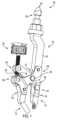
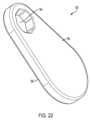
図面を参照すると、図1及び図2は、本開示の例示的実施形態によるインプラント摘出器100を図示する。インプラント摘出器100は、細長いボディ102を含む。細長いボディ102は、細長いボディ102の近位端104の周りで摘出デバイス101に取り付けるための取り付け機構103を有する。摘出デバイスは、限定されるものではないが、Tハンドル抽出デバイス101(図20および図21)、打撃部材193(図22)、またはインプラント摘出器100に摘出力を印加することができる任意の他の抽出デバイスのうちの1つまたは複数を含むことができる。 Referring to the drawings, FIGS. 1 and 2 illustrate an
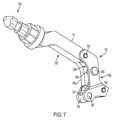
図3を参照すると、細長いボディ102は、近位端104に対向する遠位端175を有する。第1のアーム107は、細長いボディ102から延びている。以下にさらに詳細に説明するように、この特定の実施形態において、第1のアーム107の少なくとも一部は、細長いボディ102(例えば、図2および図3参照)と一体的に形成される。したがって、この特定の実施形態では、細長いボディは、第1のアームの一部と一体的に形成される。あるいは、第1のアーム107および細長いボディ102は、例えば剛性または旋回可能な接続において互いに接続することができる完全に分離した構成要素として提供することができる。 Referring to FIG. 3,
第2のアーム108は、第1のアーム107に旋回可能に接続されている。第2のアーム108は、第2のアーム108の遠位端110の回りにトルクを発生させるためのモーメントアーム105を含む。力アプリケータ126は、第1のアーム107および第2のアーム108のモーメントアーム105に動作可能に接続され、第1のアームおよび第2のアームの一方に力を加える。 A
第1のジョー112は、第1のアーム107の遠位端106に着脱可能に取り付けられ、第2のジョー113は、第2のアーム108の遠位端110に着脱可能に取り付けられる。第1のジョー112および第2のジョー113は、モジュール式であり、例えば、摘出されるインプラントの形状および実施される特定の改修手術に基づいて交換可能である。特定の例示的な実施形態に従った例示的な第1および第2のジョー112a~h、113a~hは、図23~図33に記載され、本開示の態様は、そこに示される特定の構成に限定されないが、以下により詳細に議論される。 A
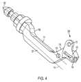
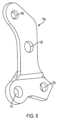
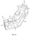
細長いボディ102は、図3~図10に詳細に分離されて示されるように、そこから延びる第1のアーム107を有し、図3に示される前面125および図4に示される背面127を有する。取り付け機構103は、細長いボディ102の近位端104の周囲および/または近傍に設けられる。図17~図19に関連して後述するように、取り付け機構は、迅速継手を含むことができる。
図3および図4を参照すると、細長いボディ102は、近位端104および遠位端175を有する。より具体的には、細長いボディは、取り付け機構103の中心軸123から細長いボディ102の本体111まで、曲げ109(例えば、S字曲げ)により外向きに湾曲する。この本体111は、曲げ109のために、取り付け機構の中心軸123から横方向にオフセットされている細長いボディ102の縦軸117を規定する。 3 and 4,
第1のアームセグメント115は、細長いボディの遠位端175から延び、取り付け機構103の中心軸123よりもさらに側方に位置する端部128に向かって終端するように本体111から内側または側方に湾曲する。第1のアームは、取り付け機構の長手方向の軸線が本体の長手方向の軸線から横方向にオフセットされているのと同じ方向に横方向に湾曲する。第1のアーム107は、全体として第1のアームを形成する右側アーム115a及び左側アーム115bを含む。第1のアームは、第1のアームセグメント115(または近位端セグメント)および第2のアームセグメント121(または遠位端アームセグメント)によっても画定される。
図3に示されるように、第1のアームセグメント115は、中心縦軸197を画定し、第2のアームセグメント121は、中心縦軸198を画定する。第1のアーム107の第2のアームセグメント121は、第1のアームセグメント115から遠位の角度αで第1のアームセグメント115から延在する。第1のアームの第2のアームセグメント121は、中心縦軸198を画定する。長手方向軸197と長手方向軸198との間の前述の角度αは、特定の例示的な実施形態では、約10°~約170°、または約80°~約160°、または約90°~約150°、または約100°~約140°(例えば、100°、101°、102°、103°、104°、105°、106°、107°、108°、109°、110°、111°、112°、113°、114°、115°、116°、117°、118°、119°、120°、121°、122°、123°、124°、125°、126°、127°、128°、129°、130°、131°、132°、133°、134°、135°、136°、137°、138°、139°、140°)の範囲とすることができる。 As shown in FIG. 3,
第1のアーム107のテール端部128は、第1のアームセグメント115および第1のアーム107の第2のアームセグメント121の両方から横方向に延在する。換言すれば、テール端部128は、細長いボディ102からのインプラント摘出器の外側端部である。 A
背面図3を参照すると、外向きに突出するピン154が、前側125に沿って長尺体の本体111に沿って設けられ、第2の外向きに突出するピン156が、その前側125に沿って第1のアーム107の第2のアームセグメント121に沿って設けられている。また、第1のアームセグメント115の長手軸線198に沿った突出ピン154,156間には貫通孔170が設けられている。第1のアーム107のテール端部128付近には、第2の貫通孔172が設けられている。 Referring to rear view 3, an outwardly projecting
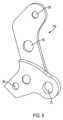
第1のアーム107の左側アーム又はプレート115b(図5~図7)は、右側アーム115aに固着されており、右側アーム115aに対応した形状の全体プロファイルを有している。プレート115bには、一対の貫通孔158、160がそれぞれ、プレートの近位端部および遠位端部の周りに配置されている。これら貫通孔は、細長いボディ102および右側アーム115a上において外方に突出するピン154、156を受け入れるように成形される。プレート115bの貫通孔158、160の間には、図9に最も良く示されているように、旋回軸164を受け入れるように構成された別の貫通孔162が存在する。以下に説明するように、旋回軸154は、第1のアーム107と第2のアーム108との間にジョイント120を画定する。別の貫通孔174は、右側アーム115aのテール端部128を中心として第2貫通孔172に対応する位置に設けられている。 A left arm or
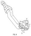
図7~図8は、細長いボディ102と完全に組み立てられた第1のアーム107を示す。組み立てられた状態において、第1のアーム107の左右のアーム間に凹部129が設けられ、第2のアーム108の通過および移動を可能にする。旋回軸164は凹部129を横切る。旋回軸164は、プレート115bを固定するための第1拡大端166(図7)と、第2アーム108の右側アームセグメント108aを保持するための第2拡大端168(図8)とを有する。したがって、組み立てられた状態において、第2のアーム108は、旋回軸164を中心として第1のアーム107を貫通して延在する。 7-8 show the
図8を参照すると、横材176は、第1のアーム107のテール端部128に向かって、またはそのテール端部128に配置されている。横材176は、プレート115bの右側アーム115aの貫通孔172および貫通孔174で受け止められる対向ピン139、140を含む。横材は、以下により詳細に説明されるように、シャフトを受け入れるように形成された、例えば、力アプリケータ126のシャフト135のうち凹んでかつねじが形成されていない非ねじ部133を受け入れるように形成されたオリフィス137を含む。 Referring to FIG. 8,
第1のアーム107の遠位端106は、第1のジョー112の近位端を解放可能に受けいれるための第1のソケット116と、第1のジョーを解放可能に固定するための第1のラッチ118とを含む。図9は、第1のジョー112を第1のソケット116に解放可能に固定するための第1のラッチ118の拡大図を示す。 The
この例示的な実施形態では、第1のラッチ116は、第1のソケット116内の位置で第1のジョー112をロックおよびロック解除するために、第1のラッチ位置と第2のラッチ位置との間で移動可能なスライダブルアクチュエータ119を含む。スライダブルアクチュエータ119は、バイアス部材(図示せず)の付勢に抗してラッチ部材178を移動させることを可能にするために、付勢されたラッチ部材178と動作可能に係合される。この特定の実施形態では、スライダブルアクチュエータ119は、ラッチ部材178が固定的に接続される裏側を有する。 In the exemplary embodiment, the
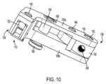
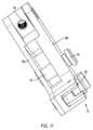
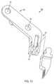
ラッチ部材178は、第1のジョー112(図23~図32)の近位端177に設けられた切欠き179と解放可能に係合し、第1のジョー112を第1のソケット116に解放可能に保持する。図9に最もよく示されるように、ラッチ部材178は、第1のジョーの相補形のメス切欠き179の内側に適合するように付勢される突出切欠き141を含むように形成されている。本開示に従ってジョーを解放可能に保持するために、他のラッチ構成を設けることができる。図1、図2および図10~図15は、第2のアーム108の例示的な構造を示す。第2のアーム108は、右アームセグメント108aと左アームセグメント108bから形成され、各アームセグ面よ108a,108bにより集合的に曲がった第2のアーム108が形成される。第2のアーム108は、モーメントアーム105および遠位アームセグメント147を画定する第1の部分を有する。モーメントアーム105は、その近位端136から第1のアームに回動可能に接続される貫通孔143までの第1の部分であると定義される。図14を参照すると、遠位アームセグメントの中心縦軸148は、モーメントアーム105又は第1の部分の中心縦軸149に対して、約10°から約180°、または約80°から約160°、または約90°から約150°、または約100°から約140°(約100°,101°,102°,103°,104°,105°,106°,107°,108°,109°,110°,111°,112°,113°,114°,115°,116°,117°,118°,119°,120°,121°,122°,123°,124°,125°,126°,127°,128°,129°,130°,131°,132°,133°,134°,135°,136°,137°,138°,139°,140°)の角度βを有する。 The
第2のアーム108は、旋回軸164を受け入れるように形成された貫通孔143を含む。突出ピン144、145は、図10、図14および図15に示されるように設けられ、左側アーム108bを固定する。第2アーム108は、旋回軸164(これはジョイント120を規定する)を介して第1アーム107に回動可能に連結されている。
第2のアーム108は、横材182を支える近位端136を含む。横材182は、横材176と同様の構造を有し、対向するピン150、153を含む。ピン150は、右側アーム108a及びピン153における貫通孔155によって受け止められ、左側アーム108bの貫通孔142によって受け止められる。横材182は、さらに、孔184、例えば、後述するように、力アプリケータ126のシャフトのねじ部186とねじ係合するように構成された雌ねじ孔を含む。
第2のアーム108の遠位端110は、第2のジョー113を解放可能に固定するための第2のラッチ124を含む。第2のラッチ124は、第2のジョー113の近位端177を解放可能に受け入れるための第2のソケット122を含む。
図12は、第2のジョー113を第2のソケット122に解放可能に固定するための第2のラッチ124の拡大図を示す。第2のラッチ124は、上述した第1のラッチ118と同様である。第2のラッチ124は、第1のラッチ位置と第2のラッチ位置との間で移動可能なスライダブルアクチュエータ188を含み、第2のジョー113をロックおよびロック解除する。スライダブルアクチュエータ188は、付勢されたラッチ部材190と動作可能に接続され、ラッチ部材190を圧縮バネ(図示せず)または他のバイアス部材の付勢に抗して移動させることを可能にする。より詳細には、この特定の実施形態では、スライダブルアクチュエータ188は、付勢されたラッチ部材190が固定的に接続される背面を有する。ラッチ部材190は、突出切欠き157を介して、第2のジョー113の近位端177に設けられた切欠き179と解放可能に係合し、第2のジョー113を第2のソケット122に解放可能に固定する。 FIG. 12 shows an enlarged view of
図1および図2に戻って参照すると、力アプリケータ126は、第1のアームおよび第2のアームのうちの1つに力を加えるために、第1のアームおよびモーメントアームに動作可能に接続されている。例えば、力アプリケータは、第2のアーム108の近位端136に上向きの力Fを与えることができる。力アプリケータは、ねじ変位装置に関連して以下に説明されるが、現在開示されている主題事項に従って第1および第2のアームの一方または両方に力を加えるために、他の力アプリケータを設けることができる。 Referring back to FIGS. 1 and 2, a
例示的な力アプリケータ126が図16に示されている。力アプリケータ126は、シャフト135と動作可能に接続された蝶ねじ130を含む。蝶ねじ130の外周は、蝶ねじ130にトルクを与えるために工具のシャフト(例えば、ドライバのシャフト)を受け入れるように形成された1つ以上のオリフィス159を含む。力アプリケータ126のシャフト135は、近位ねじ部186と、円形の長手方向断面形状を有する凹状の非ねじ部133とを含む。シャフト135は、この例示的な実施形態では、細長いボディの長手軸線117に平行な長手軸線199を有する。 An
力アプリケータ126は、横材176を保持するためのノブ131が設けられた遠位端132を有する。シャフト135の凹状の非ねじ部133は、ノブ131とシャフトのねじ部186との間に設けられている。シャフト135のこの凹状の非ねじ部133は、横材176内のオリフィス137によって回転可能に受けられる(図7および図8)。横材176は、第1のアーム107のテール端部128に取り付けられている。シャフト135のねじ部186は、蝶ねじ130の回転時にシャフト135のねじ部186を中心として第2のアーム108の基端136を軸方向に並進させるために、第2のアーム108の横材182のねじ孔184とねじ係合する。図2に示すように組み立てられると、第2のアーム108の近位端136は、それぞれが力アプリケータ126のシャフト135および縦軸132を中心とする第1のアームのテール端部128の真上に位置決めされ得る。
動作中、図1の両頭矢印の時計回り方向134への蝶ねじ130の回転は、第2のアーム108の基端136における横材182を力アプリケータ126のシャフト135のねじ部186に沿って上昇させ、第2のアーム108の先端110を第1のアーム107の先端106に向かって旋回させる。そうすることにより、第2のアーム108の遠位端110によって担持される第2のジョー113は、第1のジョー112および第2のジョー113が、摘出される図示されていないインプラントとクランプ係合(例えば、肩の修正手術の目的で上腕骨に埋め込まれた肩インプラントとクランプ係合)するまで、第1のアーム107の遠位端106によって担持される第1のジョー112に向かって移動する。第1および第2のジョーがインプラントとしっかり係合すると、摘出装置によって、インプラントが存在する骨からインプラントを摘出するための摘出力を加えることができる。 In operation, rotation of
力アプリケータ126が第2のアーム108の近位端136に上向きの力Fを与える場合、力は、近位端136からジョイント120への第2のアームの部分であるモーメントアーム105に向けられる。ジョイント120は、左側アームの貫通孔143を通るように形成されている。 When the
本開示のインプラント摘出器は、その構成のためにレバーの利点を提供する。より詳細には、例えば、図1および図2に示されるように、近位端136からジョイント120までのモーメントアーム105は、ジョイント120からの他のアームセグメントよりも有意に長い。例えば、図2を参照すると、機能モーメントアーム「M」の長さは、第2のアームの長さ「A」の少なくとも1.25、1.5、1.75、または2.0倍長くすることができ、長さ「M」は、力アプリケータ126によって供給される力の作用線からジョイント120まで測定され、長さ「A」は、ジョイント120から遠位アームセグメント147の中心縦軸148まで測定される。 The implant extractor of the present disclosure offers the advantage of a lever because of its construction. More specifically,
別の言い方をすれば、例えば、図1、図2および図14から容易に分かるように、モーメントアーム105は、(a)細長いボディの遠位端175からジョイント120までの第1アームの距離、(b)ジョイント120から第1アームの遠位端106までの第1アームの距離、および(c)ジョイント120から第2アームの遠位端110までの第2アームの距離よりも長い。第1および第2のアームに対する他のすべてのモーメントアーム長よりも長いモーメントアーム105は、第2のジョー113に比較的高いトルクを提供し、これは、摘出されるインプラントに対してより高いクランプ力を提供する。 Stated another way, as readily apparent from, for example, FIGS. (b) the distance of the first arm from the joint 120 to the
図17~図19は、迅速継手161を含む、細長いボディの近位端104を示す。この例示的な実施形態では、迅速継手161は、迅速継手の上部163の周りに比較的小さな円形断面を含む。フレア165は、上部163から迅速継手の第1のポスト167まで遠位方向に延びている。第1ポスト167は、第1ポスト167と同軸である第2ポスト169とサイズおよび断面形状が類似した楕円形またはレーストラック断面形状を有する。環状凹部171は、第1ポスト167と、第1ポストおよび第2ポストよりも有意に小さい直径を有する第2ポスト169との間に設けられる。この特定の実施形態では、環状凹部171は、楕円形またはレーストラック断面形状を有するが、他の構成を設けることもできる。 17-19 show the
迅速継手161の第2のポスト169は、多角形のブロック173に取り付けられ、または多角形のブロック173から延在している。この特定の実施形態では、ブロック173は、正八角形の形状である。多角形形状のブロック173は、円形のベース181に取り付けられているか、またはそこから延びている。円形のベース181は、多角形ブロックの幅を超える直径を有し、摘出装置(例えば、基部プレートまたは打撃プレート)を支持することができるプラトー183を提供する。 A
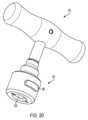
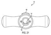
図20~図21は、T型ハンドルの形態の例示的な摘出装置101を示す。摘出装置は、T型ハンドルの遠位端のまわりに位置し、オリフィス192を含む協働する迅速継手187を介して、細長いボディ102の近位端104のまわりの取り付け機構103に接続される。協働する迅速継手187は、スプリングまたは他の付勢機構(図示せず)によって付勢されるアクチュエータ189を含む。図21に示される通常付勢された位置では、アクチュエータ開口191は、オリフィス192によって提供されるチャネルが、スプリング付勢されたアクチュエータ189によって部分的に妨害されるように、オリフィス192によって提供されるチャネルと整合されない。細長いボディ102の迅速継手がT型ハンドル101の協働する迅速継手187に挿入されると、フレア113は、スプリングまたは他の付勢部材の付勢に抗してアクチュエータ開口部191を前進させ、アクチュエータ開口部をオリフィス192によって提供されるチャネルと同時整合状態に強制的にさせて、迅速継手の遠位方向に増加する直径を収容する。アクチュエータが迅速継手の環状凹部171に到達すると、アクチュエータ189は、その通常付勢された位置に戻ることを許容され、この場合、オリフィス192によって提供されるチャネルは、再び、部分的に妨害される。部分的に妨害されたチャネルは、迅速継手の第1ポスト167および第2ポスト169の比較的大きな直径のために、T型ハンドルの移動を許容せず、T型ハンドルは、所定の位置にロックされる。T型ハンドルを取り外すために、アクチュエータ189を押し下げて、アクチュエータ開口191をオリフィス192によって提供されるチャネルと同時整合させ、第1ポスト167がアクチュエータ189をクリアできるようにする。 Figures 20-21 show an
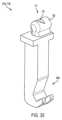
図22は、打撃部材または打撃プレート193の形態における別の摘出装置を開示している。打撃部材193は、多角形のブロック173の形状に対応する形状を有する開口194を含み、この例示的な実施形態では、正八角形の形状である。打撃部材193は、例えば外科用ハンマー(図示せず)で打撃部材193を打撃するための表面を提供するために、開口194の反対側の端部の周りに増大する幅を有する対向する平面195、196の対を有する。打撃部材193は、単独で、またはT型ハンドルまたは他の摘出装置と組み合わせて使用することができる。インプラント摘出器の他の例示的な実施形態では、打撃部材は使用されない。 FIG. 22 discloses another extraction device in the form of a striking member or
図23~図33を参照すると、非限定的ではあるが、第1のアーム107および第2のアーム108の第1および第2のソケット116および122に解放可能に接続され得るジョー112,113のいくつかの例示的な構成が示されている。 23-33, the
ジョー112、113の近位端は、第1のアーム107および第2のアーム108の第1および第2のソケット116、122に受け入れられるように構成された雄部材138を含む。ラッチ部材178、190に相補的な形状を有する切欠き179は、第1および第2のジョー112、113のための第1および第2のラッチ118、124のスライダブルアクチュエータの付勢されたラッチ部材178、190を受け入れるように構成されている。 The proximal ends of
ジョー112a~h、113a~hの先端又は部分146a~hは、略カップ形状の146a(図23)、略湾曲した146b(図24)、J字形状の146c(図25)、略ブーツ形状の146d(図26~図27)、略円筒形又は略垂直円筒形の146e(図28)、略くの字型に曲がった形状の146f(図29~図31)、略歯付きプロング形状の146g(図32)、又はフック付きプロング形状の146g(図33)に構成されている。 The tips or
図29~図31に示すように、くの字型に曲がった形状は、ブロック状の上部151aの下端に約30~60°の鋭角γで下側把持部151bを接続することにより提供されている。図29~図31に図示されるように、下部把持部151bは、略円筒状~略切頭円錐状の形状とすることができる。ユーザは、摘出されるインプラントの構成に基づいて、第1のアーム107の第1および第2のソケット116および122ならびに第2のアーム108に固定するために適切な形状のジョーを選択することが理解される。本開示に従って、他の構成を提供することができる。 As shown in FIGS. 29-31, the dogleg shape is provided by connecting the
一般に、図23~図33に開示されたジョーは交換可能であり、例えば、開示されたジョーの実施形態のいずれか1つを、第1のジョー112または第2のジョー113として使用することができる。なお、特定の実施の形態では、図32に示されたジョーの実施形態112g、113gを第2のアーム108の遠位端に接続された第2のジョー113として使用している。 Generally, the jaws disclosed in FIGS. 23-33 are interchangeable, for example, any one of the disclosed jaw embodiments can be used as
当業者には、上述の例示的な実施形態を、その広範な発明概念から逸脱することなく変更することができることが理解されるであろう。したがって、本開示は、開示された特定の実施形態に限定されるものではなく、添付の特許請求の範囲によって定義される本開示の精神および範囲内の変更をカバーすることを意図するものであることが理解されるであろう。 Those skilled in the art will appreciate that the exemplary embodiments described above can be modified without departing from the broad inventive concept thereof. Accordingly, this disclosure is not intended to be limited to the particular embodiments disclosed, but is intended to cover modifications within the spirit and scope of this disclosure as defined by the appended claims. It will be understood.
Claims (12)
Translated fromJapanese前記細長いボディの遠位端から延在する第1のアームと、
前記第1のアームの遠位端に設けられた第1のジョーと、
前記第1のアームにジョイントを介して旋回可能に接続される第2のアームであって、第2のアームの遠位端の回りにトルクを発生させるためのモーメントアームを有する第2のアームと、
前記第2のアームの遠位端に設けられた第2のジョーと、
前記第1のアームおよび前記モーメントアームに動作可能に接続され、前記第1のアームおよび前記第2のアームのうちの1つに力を加えるための力アプリケータと、
を備え、
前記第1のアーム自体には、前記第2のアームの一部分が挿通される貫通孔が形成されており、
前記第2のアームは、前記第2のアームの一部分が前記第1のアームの前記貫通孔を通った状態で延在しており、
前記第1のアームのうち前記貫通孔が形成された部分と前記第2のアームとが前記ジョイントを介して旋回可能に接続されている、インプラント摘出器。an elongated body having a proximal end for attachment to an extraction device;
a first arm extending from a distal end of the elongated body;
a first jaw at the distal end of the first arm;
a second arm pivotally connected to the first arm via a joint, the second arm having a moment arm for producing a torque about the distal end of the second arm; ,
a second jaw at the distal end of the second arm;
a force applicator operably connected to the first arm and the moment arm for applying a force to one of the first arm and the second arm;
with
The first armitself has a through hole throughwhich a portion of the second arm is inserted,
the second arm extends witha portion of the second armpassing through the through hole of the first arm;
An implant extractor, wherein a portion of the first arm in which the through hole is formed and the second arm are rotatably connected via the joint.
前記第1のジョーは、前記第2のアームセグメントに設けられており、the first jaw is provided on the second arm segment;
前記力アプリケータは、前記第2のアームの近位端に動作可能に接続され、前記第2のアームに力を加えるものであり、the force applicator is operably connected to the proximal end of the second arm and applies force to the second arm;
前記第2のアームのうち、近位端から前記ジョイントまでの部分が前記モーメントアームであり、a portion of the second arm from the proximal end to the joint is the moment arm;
前記第2のアームのうち、前記ジョイントから遠位端までの部分が遠位アームセグメントであり、a portion of the second arm from the joint to a distal end is a distal arm segment;
前記モーメントアームの中心縦軸に対する前記遠位アームセグメントの中心縦軸のなす角度(β)が、80°~160°の角度であり、an angle (β) between the central longitudinal axis of the distal arm segment and the central longitudinal axis of the moment arm is between 80° and 160°;
前記第2のアームにおいて前記モーメントアームの中心縦軸が延びる方向における近位端から前記ジョイントまでの長さ(M)が、前記第2のアームにおいて前記モーメントアームの中心縦軸が延びる方向における前記ジョイントから前記遠位アームセグメントの中心縦軸までの長さ(A)よりも長くなっている、請求項1に記載のインプラント摘出器。The length (M) from the proximal end to the joint in the direction in which the central longitudinal axis of the moment arm extends in the second arm is equal to the length (M) in the direction in which the central longitudinal axis of the moment arm extends in the second arm. 2. The implant extractor of claim 1, longer than the length (A) from the joint to the central longitudinal axis of the distal arm segment.
第1のアームセグメントと、
前記第1のアームセグメントの中心縦軸に対する前記第2のアームセグメントのなす角度(α)が、80°~160°の角度である、請求項2に記載のインプラント摘出器。The first arm is
a first arm segment;
3. The implant extractor of claim2 , wherein the angle (α) of the second arm segment with respect tothe central longitudinal axisof the first arm segmentis between 80°and 160 °.
前記第2のジョーは、前記第2のアームの遠位端に取り外し可能に取り付け可能である、請求項1に記載のインプラント摘出器。the first jaw isremovably attachable to a distal end of the first arm;
2. The implant extractor of Claim1 , wherein the second jawis removably attachable to the distal end of the second arm.
Applications Claiming Priority (5)
| Application Number | Priority Date | Filing Date | Title |
|---|---|---|---|
| US201962790176P | 2019-01-09 | 2019-01-09 | |
| US62/790,176 | 2019-01-09 | ||
| US201962909995P | 2019-10-03 | 2019-10-03 | |
| US62/909,995 | 2019-10-03 | ||
| PCT/US2020/012897WO2020146606A1 (en) | 2019-01-09 | 2020-01-09 | Implant extractor |
Publications (2)
| Publication Number | Publication Date |
|---|---|
| JP2022516447A JP2022516447A (en) | 2022-02-28 |
| JP7257519B2true JP7257519B2 (en) | 2023-04-13 |
Family
ID=69593758
Family Applications (1)
| Application Number | Title | Priority Date | Filing Date |
|---|---|---|---|
| JP2021536719AActiveJP7257519B2 (en) | 2019-01-09 | 2020-01-09 | implant extractor |
Country Status (6)
| Country | Link |
|---|---|
| US (2) | US11723781B2 (en) |
| EP (1) | EP3908231A1 (en) |
| JP (1) | JP7257519B2 (en) |
| CN (1) | CN113286567B (en) |
| AU (1) | AU2020206707B2 (en) |
| WO (1) | WO2020146606A1 (en) |
Families Citing this family (16)
| Publication number | Priority date | Publication date | Assignee | Title |
|---|---|---|---|---|
| US10456264B2 (en) | 2014-01-24 | 2019-10-29 | Tornier, Inc. | Humeral implant anchor system |
| US12023253B2 (en) | 2014-01-24 | 2024-07-02 | Howmedica Osteonics Corp. | Humeral implant anchor system |
| US10463499B2 (en) | 2016-03-25 | 2019-11-05 | Tornier, Inc. | Stemless shoulder implant with fixation components |
| US11129724B2 (en) | 2016-07-28 | 2021-09-28 | Howmedica Osteonics Corp. | Stemless prosthesis anchor component |
| MX2020003194A (en) | 2017-09-25 | 2020-12-09 | Howmedica Osteonics Corp | Patient specific stemless prosthesis anchor components. |
| US11399948B2 (en) | 2017-12-11 | 2022-08-02 | Howmedica Osteonics Corp. | Stemless prosthesis anchor components and kits |
| US20210330476A1 (en)* | 2018-03-01 | 2021-10-28 | Alden Kris | Prosthetic componenet extractor |
| EP4257090A3 (en) | 2018-10-02 | 2023-12-13 | Howmedica Osteonics Corp. | Shoulder prosthesis components and assemblies |
| US11723781B2 (en) | 2019-01-09 | 2023-08-15 | Shukla Medical | Implant extractor |
| US11660210B2 (en) | 2019-09-30 | 2023-05-30 | Shukla Medical | Implant extractor assembly and method of implant extraction |
| EP4527357A3 (en)* | 2019-10-01 | 2025-06-04 | Howmedica Osteonics Corporation | Shoulder prosthesis components and assemblies |
| USD932020S1 (en)* | 2019-10-01 | 2021-09-28 | Shukla Medical | J-loop extractor |
| US11440177B2 (en)* | 2020-03-30 | 2022-09-13 | Shukla Medical | Handle assembly for a surgical tool |
| US11779468B2 (en)* | 2020-04-14 | 2023-10-10 | Shukla Medical | Implant extractor |
| US20220023071A1 (en)* | 2020-07-21 | 2022-01-27 | Shukla Medical | Handle assembly for a medical device instrument |
| CN118285972B (en)* | 2024-06-06 | 2024-08-30 | 北京爱康宜诚医疗器材有限公司 | Femoral condyle prosthesis extraction device |
Citations (5)
| Publication number | Priority date | Publication date | Assignee | Title |
|---|---|---|---|---|
| JP2009050682A (en) | 2007-07-30 | 2009-03-12 | Japan Medical Materials Corp | Femoral component retainer |
| US20090240254A1 (en) | 2006-09-06 | 2009-09-24 | Michael Arnhold | Universal extractor for total endoprostheses of (tep) of the knee joint |
| CN102579168A (en) | 2012-03-20 | 2012-07-18 | 杭州马斯汀医疗器材有限公司 | Universal prosthetic femoral stem extractor |
| US20140207123A1 (en) | 2013-01-22 | 2014-07-24 | Erich Johann MUELLER | Knockout Tool for Minimally Invasive Prosthesis Revision |
| US20160270929A1 (en) | 2015-03-20 | 2016-09-22 | S.S. White Technologies Inc. | Locking Grip Orthopedic Implant Extraction Tool |
Family Cites Families (29)
| Publication number | Priority date | Publication date | Assignee | Title |
|---|---|---|---|---|
| US4993410A (en)* | 1989-05-01 | 1991-02-19 | Kimsey Timothy P | Prosthetic removal device |
| EP0558203A1 (en)* | 1992-02-20 | 1993-09-01 | Wright Medical Technology, Inc. | Modular trial instrument with interlock mechanism |
| US5514136A (en)* | 1994-09-06 | 1996-05-07 | Wright Medical Technology, Inc. | Surgical instrument for driving and rotating a long bone prosthesis |
| US7278995B2 (en)* | 2002-06-04 | 2007-10-09 | Howmedica Osteonics Corp. | Apparatus for securing a spinal rod system |
| US20040102783A1 (en)* | 2002-11-27 | 2004-05-27 | Sutterlin Chester E. | Powered Kerrison-like Rongeur system |
| US20050015095A1 (en)* | 2003-07-15 | 2005-01-20 | Cervitech, Inc. | Insertion instrument for cervical prostheses |
| US20050063549A1 (en)* | 2003-09-19 | 2005-03-24 | Silvestri Louis S. | Multi-function headphone system and method |
| US7776044B2 (en)* | 2004-12-21 | 2010-08-17 | Zimmer Technology, Inc. | Tibial tray inserter |
| US7625376B2 (en)* | 2005-01-26 | 2009-12-01 | Warsaw Orthopedic, Inc. | Reducing instrument for spinal surgery |
| CH697839B1 (en)* | 2005-01-28 | 2009-02-27 | Gen East Licence Kft | Set of rasp and introducer-extractor device. |
| DE202005014270U1 (en)* | 2005-09-09 | 2007-01-11 | Waldemar Link Gmbh & Co. Kg | Insertion aid for femur implant, comprises guiding unit for striker and particularly safe holding arrangement |
| US20080234765A1 (en)* | 2007-03-13 | 2008-09-25 | Depuy Spine, Inc. | Rod reduction methods and devices |
| CN201135492Y (en)* | 2007-12-03 | 2008-10-22 | 上海市第六人民医院 | Femoral Intramedullary Nail Insertion Needle Sighter |
| US20090270873A1 (en)* | 2008-04-24 | 2009-10-29 | Fabian Henry F | Spine surgery method and inserter |
| EP2323568A1 (en)* | 2008-07-29 | 2011-05-25 | Synthes GmbH | Plate holding bone forceps and method of use |
| US20100087831A1 (en)* | 2008-10-07 | 2010-04-08 | Donald Marx | Knee replacement nail remover |
| US8657833B2 (en)* | 2010-03-05 | 2014-02-25 | Greatbatch Medical S.A. | Double offset surgical tool handle assembly to provide greater offset from the coronal plane |
| JP2012154225A (en)* | 2011-01-25 | 2012-08-16 | Yamaha Motor Co Ltd | Water jet propulsion boat |
| US9339393B2 (en)* | 2011-03-28 | 2016-05-17 | Zimmer, Inc. | Orthopedic implant insertion instrument |
| US8998906B2 (en)* | 2012-07-09 | 2015-04-07 | X-Spine Systems, Inc. | Surgical implant inserter compressor |
| US9782265B2 (en)* | 2013-02-15 | 2017-10-10 | Globus Medical, Inc | Articulating and expandable vertebral implant |
| US10034774B2 (en)* | 2013-03-24 | 2018-07-31 | Tyrone Ploch | Disposable modular patella protector/clamp |
| CN104706415A (en)* | 2015-03-17 | 2015-06-17 | 苏州瑞华医院有限公司 | A pair of tongs for taking intramedullary nail |
| TWI611882B (en)* | 2016-01-26 | 2018-01-21 | 施瑞源 | Force limiting damping device |
| US10492929B2 (en)* | 2016-08-02 | 2019-12-03 | Joint Innovation Technology, Llc | Tool and method for separating a femoral cup or a femoral ball from a femoral implant |
| CN206414334U (en)* | 2016-08-31 | 2017-08-18 | 张恒 | A kind of novel orthopaedics broken nail withdrawing device |
| US11864753B2 (en)* | 2017-02-06 | 2024-01-09 | Crossroads Extremity Systems, Llc | Implant inserter |
| GB201718768D0 (en)* | 2017-11-14 | 2017-12-27 | Univ Oxford Innovation Ltd | Surgical Tool |
| US11723781B2 (en) | 2019-01-09 | 2023-08-15 | Shukla Medical | Implant extractor |
- 2020
- 2020-01-09USUS16/738,479patent/US11723781B2/enactiveActive
- 2020-01-09AUAU2020206707Apatent/AU2020206707B2/enactiveActive
- 2020-01-09JPJP2021536719Apatent/JP7257519B2/enactiveActive
- 2020-01-09CNCN202080008609.7Apatent/CN113286567B/enactiveActive
- 2020-01-09WOPCT/US2020/012897patent/WO2020146606A1/ennot_activeCeased
- 2020-01-09EPEP20705818.1Apatent/EP3908231A1/enactivePending
- 2023
- 2023-06-05USUS18/329,168patent/US20230310176A1/enactivePending
Patent Citations (5)
| Publication number | Priority date | Publication date | Assignee | Title |
|---|---|---|---|---|
| US20090240254A1 (en) | 2006-09-06 | 2009-09-24 | Michael Arnhold | Universal extractor for total endoprostheses of (tep) of the knee joint |
| JP2009050682A (en) | 2007-07-30 | 2009-03-12 | Japan Medical Materials Corp | Femoral component retainer |
| CN102579168A (en) | 2012-03-20 | 2012-07-18 | 杭州马斯汀医疗器材有限公司 | Universal prosthetic femoral stem extractor |
| US20140207123A1 (en) | 2013-01-22 | 2014-07-24 | Erich Johann MUELLER | Knockout Tool for Minimally Invasive Prosthesis Revision |
| US20160270929A1 (en) | 2015-03-20 | 2016-09-22 | S.S. White Technologies Inc. | Locking Grip Orthopedic Implant Extraction Tool |
Also Published As
| Publication number | Publication date |
|---|---|
| AU2020206707B2 (en) | 2022-12-08 |
| CN113286567A (en) | 2021-08-20 |
| US20230310176A1 (en) | 2023-10-05 |
| WO2020146606A1 (en) | 2020-07-16 |
| AU2020206707A1 (en) | 2021-07-08 |
| US20200214853A1 (en) | 2020-07-09 |
| CN113286567B (en) | 2024-08-02 |
| US11723781B2 (en) | 2023-08-15 |
| JP2022516447A (en) | 2022-02-28 |
| EP3908231A1 (en) | 2021-11-17 |
Similar Documents
| Publication | Publication Date | Title |
|---|---|---|
| JP7257519B2 (en) | implant extractor | |
| US11219357B2 (en) | Endoscope with improved clamping connection for easy dismantling | |
| US9089440B2 (en) | Knockout tool for minimally invasive prosthesis revision | |
| EP1176912B1 (en) | Retractor for use in endoscopic surgery | |
| CN104994793B (en) | Disposable capsulorhexis forceps | |
| JP5248498B2 (en) | Tool for removing pins | |
| CN110151256B (en) | Microsurgical holding and/or cutting instrument | |
| CN106794067B (en) | cup driver | |
| US20050113841A1 (en) | Guide clamp for guiding placement of a guide wire in a femur | |
| US20080154277A1 (en) | Tool apparatus for locking a spinal rod in an anchoring device therefor | |
| KR20050109916A (en) | Surgical retractor system | |
| JP2004516062A (en) | Universal handle for surgical devices | |
| EP1883358A1 (en) | A surgical instrument | |
| JP2011527613A (en) | Minimal open surgery tool for hip prosthesis | |
| AU2016200461A1 (en) | Tissue repair kit | |
| US20120197304A1 (en) | Expansion and compression instrument for fracture fixation | |
| US10441337B2 (en) | Distraction and compression in one plier | |
| AU2017324821B2 (en) | Medical instrument with cleaning gap in the closure region | |
| US20160213492A1 (en) | Impactor adaptor and screw assembly | |
| CN110403756B (en) | Ophthalmic microsurgery instrument and operation method thereof | |
| EP0550118A1 (en) | Endoprosthesis and appliance for driving it in or out | |
| US10485599B2 (en) | Surgical cable passer instrument and methods | |
| CN115768379A (en) | Medical Implant Delivery Systems | |
| US20210121167A1 (en) | Multifunction quick connect socket for surgical retraction tools | |
| CA2805977C (en) | Expansion and compression instrument for fracture fixation |
Legal Events
| Date | Code | Title | Description |
|---|---|---|---|
| A521 | Request for written amendment filed | Free format text:JAPANESE INTERMEDIATE CODE: A523 Effective date:20210707 | |
| A621 | Written request for application examination | Free format text:JAPANESE INTERMEDIATE CODE: A621 Effective date:20210707 | |
| A977 | Report on retrieval | Free format text:JAPANESE INTERMEDIATE CODE: A971007 Effective date:20220729 | |
| A131 | Notification of reasons for refusal | Free format text:JAPANESE INTERMEDIATE CODE: A131 Effective date:20220809 | |
| A521 | Request for written amendment filed | Free format text:JAPANESE INTERMEDIATE CODE: A523 Effective date:20221003 | |
| A131 | Notification of reasons for refusal | Free format text:JAPANESE INTERMEDIATE CODE: A131 Effective date:20221101 | |
| A521 | Request for written amendment filed | Free format text:JAPANESE INTERMEDIATE CODE: A523 Effective date:20230112 | |
| TRDD | Decision of grant or rejection written | ||
| A01 | Written decision to grant a patent or to grant a registration (utility model) | Free format text:JAPANESE INTERMEDIATE CODE: A01 Effective date:20230307 | |
| A61 | First payment of annual fees (during grant procedure) | Free format text:JAPANESE INTERMEDIATE CODE: A61 Effective date:20230403 | |
| R150 | Certificate of patent or registration of utility model | Ref document number:7257519 Country of ref document:JP Free format text:JAPANESE INTERMEDIATE CODE: R150 |