JP7256281B2 - Rehabilitation exercise device for upper and lower limbs - Google Patents
Rehabilitation exercise device for upper and lower limbsDownload PDFInfo
- Publication number
- JP7256281B2 JP7256281B2JP2021546867AJP2021546867AJP7256281B2JP 7256281 B2JP7256281 B2JP 7256281B2JP 2021546867 AJP2021546867 AJP 2021546867AJP 2021546867 AJP2021546867 AJP 2021546867AJP 7256281 B2JP7256281 B2JP 7256281B2
- Authority
- JP
- Japan
- Prior art keywords
- base plate
- unit
- pair
- plate
- connecting rod
- Prior art date
- Legal status (The legal status is an assumption and is not a legal conclusion. Google has not performed a legal analysis and makes no representation as to the accuracy of the status listed.)
- Active
Links
Images


Classifications
- A—HUMAN NECESSITIES
- A61—MEDICAL OR VETERINARY SCIENCE; HYGIENE
- A61H—PHYSICAL THERAPY APPARATUS, e.g. DEVICES FOR LOCATING OR STIMULATING REFLEX POINTS IN THE BODY; ARTIFICIAL RESPIRATION; MASSAGE; BATHING DEVICES FOR SPECIAL THERAPEUTIC OR HYGIENIC PURPOSES OR SPECIFIC PARTS OF THE BODY
- A61H1/00—Apparatus for passive exercising; Vibrating apparatus; Chiropractic devices, e.g. body impacting devices, external devices for briefly extending or aligning unbroken bones
- A61H1/02—Stretching or bending or torsioning apparatus for exercising
- A61H1/0237—Stretching or bending or torsioning apparatus for exercising for the lower limbs
- A61H1/024—Knee
- A—HUMAN NECESSITIES
- A61—MEDICAL OR VETERINARY SCIENCE; HYGIENE
- A61H—PHYSICAL THERAPY APPARATUS, e.g. DEVICES FOR LOCATING OR STIMULATING REFLEX POINTS IN THE BODY; ARTIFICIAL RESPIRATION; MASSAGE; BATHING DEVICES FOR SPECIAL THERAPEUTIC OR HYGIENIC PURPOSES OR SPECIFIC PARTS OF THE BODY
- A61H1/00—Apparatus for passive exercising; Vibrating apparatus; Chiropractic devices, e.g. body impacting devices, external devices for briefly extending or aligning unbroken bones
- A61H1/02—Stretching or bending or torsioning apparatus for exercising
- A61H1/0237—Stretching or bending or torsioning apparatus for exercising for the lower limbs
- A61H1/0244—Hip
- A—HUMAN NECESSITIES
- A61—MEDICAL OR VETERINARY SCIENCE; HYGIENE
- A61H—PHYSICAL THERAPY APPARATUS, e.g. DEVICES FOR LOCATING OR STIMULATING REFLEX POINTS IN THE BODY; ARTIFICIAL RESPIRATION; MASSAGE; BATHING DEVICES FOR SPECIAL THERAPEUTIC OR HYGIENIC PURPOSES OR SPECIFIC PARTS OF THE BODY
- A61H1/00—Apparatus for passive exercising; Vibrating apparatus; Chiropractic devices, e.g. body impacting devices, external devices for briefly extending or aligning unbroken bones
- A61H1/02—Stretching or bending or torsioning apparatus for exercising
- A61H1/0237—Stretching or bending or torsioning apparatus for exercising for the lower limbs
- A61H1/0266—Foot
- A—HUMAN NECESSITIES
- A61—MEDICAL OR VETERINARY SCIENCE; HYGIENE
- A61H—PHYSICAL THERAPY APPARATUS, e.g. DEVICES FOR LOCATING OR STIMULATING REFLEX POINTS IN THE BODY; ARTIFICIAL RESPIRATION; MASSAGE; BATHING DEVICES FOR SPECIAL THERAPEUTIC OR HYGIENIC PURPOSES OR SPECIFIC PARTS OF THE BODY
- A61H1/00—Apparatus for passive exercising; Vibrating apparatus; Chiropractic devices, e.g. body impacting devices, external devices for briefly extending or aligning unbroken bones
- A61H1/02—Stretching or bending or torsioning apparatus for exercising
- A61H1/0274—Stretching or bending or torsioning apparatus for exercising for the upper limbs
- A61H1/0277—Elbow
- A—HUMAN NECESSITIES
- A61—MEDICAL OR VETERINARY SCIENCE; HYGIENE
- A61H—PHYSICAL THERAPY APPARATUS, e.g. DEVICES FOR LOCATING OR STIMULATING REFLEX POINTS IN THE BODY; ARTIFICIAL RESPIRATION; MASSAGE; BATHING DEVICES FOR SPECIAL THERAPEUTIC OR HYGIENIC PURPOSES OR SPECIFIC PARTS OF THE BODY
- A61H1/00—Apparatus for passive exercising; Vibrating apparatus; Chiropractic devices, e.g. body impacting devices, external devices for briefly extending or aligning unbroken bones
- A61H1/02—Stretching or bending or torsioning apparatus for exercising
- A61H1/0274—Stretching or bending or torsioning apparatus for exercising for the upper limbs
- A61H1/0281—Shoulder
- A—HUMAN NECESSITIES
- A61—MEDICAL OR VETERINARY SCIENCE; HYGIENE
- A61H—PHYSICAL THERAPY APPARATUS, e.g. DEVICES FOR LOCATING OR STIMULATING REFLEX POINTS IN THE BODY; ARTIFICIAL RESPIRATION; MASSAGE; BATHING DEVICES FOR SPECIAL THERAPEUTIC OR HYGIENIC PURPOSES OR SPECIFIC PARTS OF THE BODY
- A61H1/00—Apparatus for passive exercising; Vibrating apparatus; Chiropractic devices, e.g. body impacting devices, external devices for briefly extending or aligning unbroken bones
- A61H1/02—Stretching or bending or torsioning apparatus for exercising
- A61H1/0274—Stretching or bending or torsioning apparatus for exercising for the upper limbs
- A61H1/0285—Hand
- A—HUMAN NECESSITIES
- A63—SPORTS; GAMES; AMUSEMENTS
- A63B—APPARATUS FOR PHYSICAL TRAINING, GYMNASTICS, SWIMMING, CLIMBING, OR FENCING; BALL GAMES; TRAINING EQUIPMENT
- A63B22/00—Exercising apparatus specially adapted for conditioning the cardio-vascular system, for training agility or co-ordination of movements
- A63B22/02—Exercising apparatus specially adapted for conditioning the cardio-vascular system, for training agility or co-ordination of movements with movable endless bands, e.g. treadmills
- A—HUMAN NECESSITIES
- A61—MEDICAL OR VETERINARY SCIENCE; HYGIENE
- A61H—PHYSICAL THERAPY APPARATUS, e.g. DEVICES FOR LOCATING OR STIMULATING REFLEX POINTS IN THE BODY; ARTIFICIAL RESPIRATION; MASSAGE; BATHING DEVICES FOR SPECIAL THERAPEUTIC OR HYGIENIC PURPOSES OR SPECIFIC PARTS OF THE BODY
- A61H2201/00—Characteristics of apparatus not provided for in the preceding codes
- A61H2201/01—Constructive details
- A61H2201/0157—Constructive details portable
- A—HUMAN NECESSITIES
- A61—MEDICAL OR VETERINARY SCIENCE; HYGIENE
- A61H—PHYSICAL THERAPY APPARATUS, e.g. DEVICES FOR LOCATING OR STIMULATING REFLEX POINTS IN THE BODY; ARTIFICIAL RESPIRATION; MASSAGE; BATHING DEVICES FOR SPECIAL THERAPEUTIC OR HYGIENIC PURPOSES OR SPECIFIC PARTS OF THE BODY
- A61H2201/00—Characteristics of apparatus not provided for in the preceding codes
- A61H2201/01—Constructive details
- A61H2201/0161—Size reducing arrangements when not in use, for stowing or transport
- A—HUMAN NECESSITIES
- A61—MEDICAL OR VETERINARY SCIENCE; HYGIENE
- A61H—PHYSICAL THERAPY APPARATUS, e.g. DEVICES FOR LOCATING OR STIMULATING REFLEX POINTS IN THE BODY; ARTIFICIAL RESPIRATION; MASSAGE; BATHING DEVICES FOR SPECIAL THERAPEUTIC OR HYGIENIC PURPOSES OR SPECIFIC PARTS OF THE BODY
- A61H2201/00—Characteristics of apparatus not provided for in the preceding codes
- A61H2201/01—Constructive details
- A61H2201/0192—Specific means for adjusting dimensions
- A—HUMAN NECESSITIES
- A61—MEDICAL OR VETERINARY SCIENCE; HYGIENE
- A61H—PHYSICAL THERAPY APPARATUS, e.g. DEVICES FOR LOCATING OR STIMULATING REFLEX POINTS IN THE BODY; ARTIFICIAL RESPIRATION; MASSAGE; BATHING DEVICES FOR SPECIAL THERAPEUTIC OR HYGIENIC PURPOSES OR SPECIFIC PARTS OF THE BODY
- A61H2201/00—Characteristics of apparatus not provided for in the preceding codes
- A61H2201/12—Driving means
- A61H2201/1207—Driving means with electric or magnetic drive
- A61H2201/1215—Rotary drive
- A—HUMAN NECESSITIES
- A61—MEDICAL OR VETERINARY SCIENCE; HYGIENE
- A61H—PHYSICAL THERAPY APPARATUS, e.g. DEVICES FOR LOCATING OR STIMULATING REFLEX POINTS IN THE BODY; ARTIFICIAL RESPIRATION; MASSAGE; BATHING DEVICES FOR SPECIAL THERAPEUTIC OR HYGIENIC PURPOSES OR SPECIFIC PARTS OF THE BODY
- A61H2201/00—Characteristics of apparatus not provided for in the preceding codes
- A61H2201/14—Special force transmission means, i.e. between the driving means and the interface with the user
- A—HUMAN NECESSITIES
- A61—MEDICAL OR VETERINARY SCIENCE; HYGIENE
- A61H—PHYSICAL THERAPY APPARATUS, e.g. DEVICES FOR LOCATING OR STIMULATING REFLEX POINTS IN THE BODY; ARTIFICIAL RESPIRATION; MASSAGE; BATHING DEVICES FOR SPECIAL THERAPEUTIC OR HYGIENIC PURPOSES OR SPECIFIC PARTS OF THE BODY
- A61H2201/00—Characteristics of apparatus not provided for in the preceding codes
- A61H2201/16—Physical interface with patient
- A61H2201/1602—Physical interface with patient kind of interface, e.g. head rest, knee support or lumbar support
- A61H2201/1635—Hand or arm, e.g. handle
- A61H2201/1638—Holding means therefor
- A—HUMAN NECESSITIES
- A61—MEDICAL OR VETERINARY SCIENCE; HYGIENE
- A61H—PHYSICAL THERAPY APPARATUS, e.g. DEVICES FOR LOCATING OR STIMULATING REFLEX POINTS IN THE BODY; ARTIFICIAL RESPIRATION; MASSAGE; BATHING DEVICES FOR SPECIAL THERAPEUTIC OR HYGIENIC PURPOSES OR SPECIFIC PARTS OF THE BODY
- A61H2201/00—Characteristics of apparatus not provided for in the preceding codes
- A61H2201/16—Physical interface with patient
- A61H2201/1602—Physical interface with patient kind of interface, e.g. head rest, knee support or lumbar support
- A61H2201/164—Feet or leg, e.g. pedal
- A61H2201/1642—Holding means therefor
- A—HUMAN NECESSITIES
- A61—MEDICAL OR VETERINARY SCIENCE; HYGIENE
- A61H—PHYSICAL THERAPY APPARATUS, e.g. DEVICES FOR LOCATING OR STIMULATING REFLEX POINTS IN THE BODY; ARTIFICIAL RESPIRATION; MASSAGE; BATHING DEVICES FOR SPECIAL THERAPEUTIC OR HYGIENIC PURPOSES OR SPECIFIC PARTS OF THE BODY
- A61H2201/00—Characteristics of apparatus not provided for in the preceding codes
- A61H2201/16—Physical interface with patient
- A61H2201/1657—Movement of interface, i.e. force application means
- A61H2201/1676—Pivoting
- A—HUMAN NECESSITIES
- A61—MEDICAL OR VETERINARY SCIENCE; HYGIENE
- A61H—PHYSICAL THERAPY APPARATUS, e.g. DEVICES FOR LOCATING OR STIMULATING REFLEX POINTS IN THE BODY; ARTIFICIAL RESPIRATION; MASSAGE; BATHING DEVICES FOR SPECIAL THERAPEUTIC OR HYGIENIC PURPOSES OR SPECIFIC PARTS OF THE BODY
- A61H2201/00—Characteristics of apparatus not provided for in the preceding codes
- A61H2201/50—Control means thereof
- A61H2201/5058—Sensors or detectors
- A61H2201/5064—Position sensors
- A—HUMAN NECESSITIES
- A61—MEDICAL OR VETERINARY SCIENCE; HYGIENE
- A61H—PHYSICAL THERAPY APPARATUS, e.g. DEVICES FOR LOCATING OR STIMULATING REFLEX POINTS IN THE BODY; ARTIFICIAL RESPIRATION; MASSAGE; BATHING DEVICES FOR SPECIAL THERAPEUTIC OR HYGIENIC PURPOSES OR SPECIFIC PARTS OF THE BODY
- A61H2201/00—Characteristics of apparatus not provided for in the preceding codes
- A61H2201/50—Control means thereof
- A61H2201/5097—Control means thereof wireless
Landscapes
- Health & Medical Sciences (AREA)
- Physical Education & Sports Medicine (AREA)
- General Health & Medical Sciences (AREA)
- Animal Behavior & Ethology (AREA)
- Rehabilitation Therapy (AREA)
- Life Sciences & Earth Sciences (AREA)
- Pain & Pain Management (AREA)
- Epidemiology (AREA)
- Public Health (AREA)
- Veterinary Medicine (AREA)
- Cardiology (AREA)
- Vascular Medicine (AREA)
- Rehabilitation Tools (AREA)
Description
Translated fromJapanese本発明は上肢及び下肢用リハビリ運動装置に関し、より具体的には、上肢または下肢を載置して、上肢または下肢のリハビリ運動が行なえる上肢及び下肢用リハビリ運動装置に関する。 TECHNICAL FIELD The present invention relates to a rehabilitation exercise apparatus for upper and lower limbs, and more particularly to a rehabilitation exercise apparatus for upper and lower limbs on which upper or lower limbs can be placed for rehabilitation exercise.
一般に、人体の各関節部位は、関節部位に隣接する部位が関節部位を基準に回転可能な構造を有する。 In general, each joint part of the human body has a structure in which a part adjacent to the joint part can rotate based on the joint part.
一方、高齢者や筋力が弱いリハビリ患者は自らの運動が不能で、健康な人に比べて、関節の運動に難渋していて、実質的に運動が必要であるにも一般的な運動器具にて運動を行うことが現実的に困難な実情である。 On the other hand, elderly people and rehabilitation patients with weak muscles are unable to exercise themselves and have difficulty in exercising their joints compared to healthy people. It is the reality that it is difficult to exercise in reality.
筋力が弱くなったり、損傷した関節が放置され続けると、筋肉や関節が徐々に固まって動く際に、痛みを感じるようになり、神経が回復されても、通常の活動に支障をきたすことがあり得る。 If muscle strength weakens or damaged joints are left untreated, the muscles and joints gradually harden and become painful when moving. could be.
また、手首及び肩のような関節部位を手術した患者の場合には、自らの運動が不能であるから、筋肉が弱くなって円滑な栄養の供給が行われていなくて手首及び肩の関節部位が堅くなりながら固まるおそれがある。 In addition, in the case of patients who have undergone surgery on joints such as wrists and shoulders, they are unable to exercise themselves, so their muscles are weakened and nourishment is not supplied smoothly to the joints of wrists and shoulders. There is a possibility that it will harden while becoming hard.
これにより、関節の変形を防止し、正常活動に復帰するためには、長時間の痛みを伴うリハビリ運動を行うべきである。 Therefore, long-term painful rehabilitation exercises should be performed to prevent joint deformation and return to normal activity.
この問題を改善するために、高齢者や筋力が弱いリハビリ患者に受動的運動を付与して、関節の運動を行わせるためのリハビリ運動装置の先行技術として、韓国登録特許公報第10-1163903号に脳卒中患者の上肢リハビリのための外骨格ロボットが開示されている。 In order to solve this problem, Korean Patent Publication No. 10-1163903 is a prior art of a rehabilitation exercise device for imparting passive exercise to elderly people and rehabilitation patients with weak muscles to exercise their joints. discloses an exoskeleton robot for upper extremity rehabilitation of stroke patients.
先行技術に開示されたリハビリ機器は不必要に複雑な構成になっており、購入及び設置に伴う費用の負担が大きく、より多くのユーザーに恩恵を提供しにくい問題がある。また、リハビリ運動装置の移動が容易ではなく、ほとんどのユーザーがリハビリ運動装置がある場所に移動して運動を行うべきなので、使用上の煩わしい問題もある。 The rehabilitation equipment disclosed in the prior art has an unnecessarily complicated structure, has a high cost burden associated with purchase and installation, and is difficult to provide benefits to more users. In addition, it is not easy to move the rehabilitation exercise device, and most users should move to a place where the rehabilitation exercise device is located to exercise.
本発明は、前記のような点を勘案して案出されたものであり、本発明は、リハビリ患者の状態に合わせて上肢または下肢の載置角度を簡便に調整してリハビリ運動が行なえて、構造を単純化させて購入及び設置に伴う費用の負担を最小化して、移動が便利でお年寄りや筋力が弱いリハビリ患者が容易に移動させて、机、椅子、マットレスなどに安着してから、上肢または下肢を簡便に載置し、上肢または下肢の各関節を正常運動に近似したリハビリ運動が行なえる上肢及び下肢用リハビリ運動装置を提供することを発明の目的とする。 The present invention has been devised in consideration of the above points, and the present invention enables rehabilitation exercises to be performed by simply adjusting the placement angle of the upper or lower limbs according to the condition of the rehabilitation patient. , The structure is simplified to minimize the cost of purchase and installation, and it is convenient to move, so that the elderly and rehabilitation patients with weak muscles can easily move it and sit on a desk, chair, mattress, etc. SUMMARY OF THE INVENTION It is therefore an object of the present invention to provide a rehabilitation exercise apparatus for upper and lower limbs, on which the upper and lower limbs can be simply placed and the joints of the upper and lower limbs can be exercised in a manner approximating normal exercise.
本発明の目的は、ベースプレートと、手または足を支持する第1支持部と、上肢の前腕または下肢の下腿を支持する第2支持部と、上肢の上腕または下肢の大腿を支持する第3支持部を含むリハビリ運動ユニットが載置して、一側が前記ベースプレートの板面に沿って水平移動可能に結合される載置プレートと、両側がそれぞれ前記ベースプレートと前記載置プレートに回転可能に結合されて、前記載置プレートの一側が前記ベースプレートの板面に沿って水平移動する際に回転して、前記ベースプレートと前記載置プレートの角度を調整するリンク部材を含むことを特徴とする上肢及び下肢用リハビリ運動装置により達成される。 The object of the present invention is to provide a base plate, a first support for supporting the hand or foot, a second support for supporting the forearm of the upper leg or the lower leg of the lower leg, and a third support for supporting the upper arm of the upper leg or the thigh of the lower leg. a resting plate on which the rehabilitation exercise unit including the parts is placed, one side of which is coupled horizontally along the surface of the base plate, and both sides of which are rotatably coupled to the base plate and the placing plate, respectively. and a link member that adjusts the angle between the base plate and the mounting plate by rotating when one side of the mounting plate moves horizontally along the surface of the base plate. This is achieved by a rehabilitation exercise device for
ここで、前記載置プレートの一側に回転可能に結合され、前記第3支持部に向かって並んで延びた一対の延長ブラケットと、前記一対の延長ブラケットを連結する連結棒と、前記ベースプレートに前記一対の延長ブラケットの長手方向に沿って間隔を置いて形成され、前記ベースプレートと前記載置プレートとの間の傾斜角度に対応して前記連結棒が選択的に係止する複数の係止爪と、前記連結棒が選択された前記係止爪に係止した状態が保持されるように固定する固定ユニットをさらに含むことができる。 Here, a pair of extension brackets rotatably coupled to one side of the mounting plate and extending side by side toward the third support portion, a connecting rod connecting the pair of extension brackets, and the base plate. A plurality of locking claws formed at intervals along the longitudinal direction of the pair of extension brackets and selectively locked by the connecting rod corresponding to the inclination angle between the base plate and the mounting plate. and a fixing unit for fixing the connecting rod to the selected locking pawl so as to maintain the locked state.
また、前記ベースプレートは、それぞれの前記係止爪に対応する位置に、前記ベースプレートの一側の側面が陥没して形成された複数の断続溝と、それぞれの前記断続溝に前記係止爪に向かって貫通して形成され、上向き対角方向に開放された移動孔を含み、前記固定ユニットは、一側が前記連結棒に連結され、他側が前記移動孔を介して前記ベースプレートの外部に延びる延長ユニットと、前記延長ユニットの他側に結合されて、前記断続溝に挿入される固定位置と、前記断続溝から離脱される離脱位置との間を移動可能に前記延長ユニットに結合されるユニット本体を含み、前記ユニット本体の前記固定位置で前記延長ユニットの前記移動孔への移動が阻止され、前記連結棒が前記係止爪に係止する状態が保持され、前記ユニット本体の前記離脱位置で前記延長ユニットが前記移動孔を介して他の移動孔への移動が可能になり、複数の前記係止爪の中のいずれか一つに選択的に前記連結棒が移動可能である。 Further, the base plate includes a plurality of intermittent grooves formed by recessing one side surface of the base plate at positions corresponding to the respective locking claws, and a plurality of intermittent grooves extending toward the locking claws in the respective intermittent grooves. an extension unit having one side connected to the connecting rod and the other side extending to the outside of the base plate through the movement hole. and a unit body coupled to the extension unit movably between a fixed position where it is coupled to the other side of the extension unit and inserted into the intermittent groove, and a disengaged position where it is separated from the intermittent groove. movement of the extension unit to the movement hole is blocked at the fixed position of the unit main body, a state in which the connecting rod is engaged with the engaging claw is maintained, and the disengaged position of the unit main body is the The extension unit can move to another moving hole through the moving hole, and the connecting rod can selectively move to any one of the plurality of locking claws.
そして、前記延長ユニットは長手方向に沿って一定の間隔を置いて一対の動作溝が形成されて、前記ユニット本体は前記固定位置と前記離脱位置でそれぞれ前記動作溝に係止する動作爪を含むことができる。 The extension unit is formed with a pair of movement grooves at regular intervals along the longitudinal direction, and the unit main body includes movement claws respectively engaged with the movement grooves at the fixed position and the detached position. be able to.
そして、それぞれの前記係止爪は、前記連結棒の長さに対応して前記長手方向と交差する方向に延びて形成されて、前記固定ユニットが設けられた方向がその反対方向より係止解除される方向にもう突出して、前記固定ユニットの操作を介して前記連結棒を前記係止爪から解除する際に、前記固定ユニットが設けられた方向の係止が解除される際に、前記連接棒全体が前記係止爪から係止解除されることができる。 Each of the locking claws is formed to extend in a direction intersecting with the longitudinal direction corresponding to the length of the connecting rod, and the direction in which the fixing unit is provided releases the locking from the opposite direction. When the connecting rod is released from the locking pawl through the operation of the fixing unit, the connection in the direction in which the fixing unit is provided is released. The entire rod can be unlocked from the pawl.
そして、前記連結棒が前記係止爪に係止されるように弾性力を提供する弾性ユニットをさらに含むことができる。 Further, an elastic unit may be provided to provide elastic force so that the connecting rod is locked to the locking claw.
そして、前記載置プレートは、前記ベースプレートに沿って水平移動する移動ブラケットと、前記移動ブラケットの両側に回転可能に結合される一対の載置ブラケットと、前記移動ブラケットと前記載置ブラケットによって支持されて、前記リハビリ運動ユニットが載置される板状の載置部を含み、一対の前記延長ブラケットが前記移動ブラケットに回転可能に結合され、前記延長ブラケットの移動に同期されて前記移動ブラケットが移動して、前記弾性ユニットは前記移動ブラケットに設けられて一対の前記延長ブラケットの中の少なくとも一つを下部方向に押圧する板バネを含むことができる。 The mounting plate is supported by a moving bracket horizontally moved along the base plate, a pair of mounting brackets rotatably coupled to both sides of the moving bracket, and the moving bracket and the mounting bracket. and a plate-shaped mounting portion on which the rehabilitation exercise unit is mounted, the pair of extension brackets are rotatably coupled to the movement bracket, and the movement bracket moves in synchronism with the movement of the extension bracket. The elastic unit may include a leaf spring installed on the moving bracket to press at least one of the pair of extension brackets downward.
他の例として、前記固定ユニットは、前記ベースプレートと前記載置プレートとの間の角度調整に応じて前記連結棒と共に前記ベースプレートに沿って往復移動する一対のユニット本体と、前記ベースプレートの外側に設けられ、前記一対のユニット本体に回転可能に結合される一対の動作レバーと、前記ベースプレートの内側に設けられ、前記一対の動作レバーの回転に連動して回転するように前記一対のユニット本体に回転可能に結合される一対の連動レバーと、前記連結棒の両側のエッジに前記連動レバーに向かって設けられ、前記連動レバーの回転に応じて押圧または押圧解除される一対の連動ブラケットを含むことができる。 As another example, the fixing unit includes a pair of unit main bodies that reciprocate along the base plate together with the connecting rod according to the angle adjustment between the base plate and the mounting plate, and a pair of unit main bodies provided outside the base plate. a pair of operating levers rotatably coupled to the pair of unit bodies; and a pair of operating levers provided inside the base plate and rotating to the pair of unit bodies so as to rotate in conjunction with the rotation of the pair of operating levers. A pair of interlocking levers that can be coupled together, and a pair of interlocking brackets that are provided on both edges of the connecting rod toward the interlocking levers and are pressed or released according to the rotation of the interlocking levers. can.
別の例として、前記固定ユニットは、前記ベースプレートに前記複数の係止爪と並んで前記ベースプレートの長手方向に沿って連続的な波形状で形成された複数の補助係止爪と、前記ベースプレートに前記補助係止爪と等しいピッチで設けられた複数の係止ピンと、前記ベースプレートと前記載置プレートとの間の角度調整に応じて前記連結棒と共に前記ベースプレートに沿って往復移動し、前記複数の補助係止爪に選択的に載置されるユニット本体と、前記ベースプレートの外側に設けられ、前記ユニット本体に回転可能に結合される動作レバーと、前記ベースプレートの外側に設けられ、前記動作レバーの回転に連動して回転するように、前記ユニット本体に回転可能に結合され、前記複数の係止ピンに選択的に係止または係止解除される連動レバーを含むことができる。 As another example, the fixing unit may include a plurality of auxiliary locking claws formed on the base plate in parallel with the plurality of locking claws and formed in a continuous wavy shape along the longitudinal direction of the base plate; A plurality of locking pins provided at the same pitch as the auxiliary locking claws reciprocate along the base plate together with the connecting rod according to the angle adjustment between the base plate and the mounting plate, A unit body selectively placed on an auxiliary locking claw, an operation lever provided outside the base plate and rotatably coupled to the unit body, and an operation lever provided outside the base plate for the operation lever. An interlocking lever may be included that is rotatably coupled to the unit body so as to rotate in conjunction with rotation, and that selectively engages or unlocks the plurality of locking pins.
本発明によると、リハビリ患者の状態に合わせて上肢または下肢の載置角度を簡便に調整してリハビリ運動が行なえて、構造を単純化させて購入及び設置に伴う費用の負担を最小化して、移動が便利でお年寄りや筋力が弱いリハビリ患者が容易に移動させて、机、椅子、マットレスなどに安着してから、上肢または下肢を簡便に載置し、上肢または下肢の各関節を正常運動に近似したリハビリ運動が行なえる。 INDUSTRIAL APPLICABILITY According to the present invention, rehabilitation exercise can be performed by simply adjusting the mounting angle of the upper or lower limb according to the condition of the rehabilitation patient, and the structure is simplified to minimize the cost of purchase and installation. It is convenient to move, so that the elderly and rehabilitation patients with weak muscles can easily move and sit on a desk, chair, mattress, etc., and then place the upper or lower limbs easily to keep each joint of the upper or lower limbs normal. Rehabilitation exercise similar to exercise can be performed.
本発明は、上肢及び下肢用リハビリ運動装置に関するものであり、ベースプレートと、手または足を支持する第1支持部と、上肢の前腕または下肢の下腿を支持する第2支持部と、上肢の上腕または下肢の大腿を支持する第3支持部を含むリハビリ運動ユニットが載置して、一側が前記ベースプレートの板面に沿って水平移動可能に結合される載置プレートと、両側がそれぞれ前記ベースプレートと前記載置プレートに回転可能に結合されて、前記載置プレートの一側が前記ベースプレートの板面に沿って水平移動する際に回転して、前記ベースプレートと前記載置プレートの角度を調整するリンク部材を含むことを特徴とする。 The present invention relates to a rehabilitation exercise device for upper and lower limbs, comprising a base plate, a first supporting part for supporting hands or feet, a second supporting part for supporting the forearms of the upper limbs or the lower legs of the lower limbs, and the upper arms of the upper limbs. Alternatively, a resting plate on which a rehabilitation exercise unit including a third supporting part for supporting the thigh of the lower leg is placed, one side of which is coupled to the base plate so as to be horizontally movable along the plate surface of the base plate, and both sides of which are respectively connected to the base plate. A link member that is rotatably coupled to the mounting plate and rotates when one side of the mounting plate horizontally moves along the plate surface of the base plate to adjust an angle between the base plate and the mounting plate. characterized by comprising
本発明の利点および特徴、そしてそれらを達成する方法は添付される図面と共に詳細に後述されている実施形態を参照すると明確になるだろう。しかし、本発明は、以下で開示される実施形態に限定されるものではなく、異なる多様な形態で具現されることができ、単に本実施形態は、本発明の開示が完全にして、本発明が属する技術分野の通常の技術者に本発明の範疇を完全に知らせるために提供されているものであり、本発明は、請求項の範疇により定義されるだけである。 Advantages and features of the present invention, as well as the manner in which they are achieved, will become apparent with reference to the embodiments described in detail below in conjunction with the accompanying drawings. This invention, however, should not be limited to the embodiments disclosed below, and may be embodied in many different forms; is provided to fully convey the scope of the invention to those of ordinary skill in the art to which it belongs, the invention being defined only by the scope of the claims.
本明細書で使用する用語は、実施形態を説明するためのものであり、本発明を制限するものではない。本明細書では、単数形は、文句で特に言及しない限り、複数形も含む。明細書で使用される「含む(comprises)」及び/または「含んでいる(comprising)」は、言及された構成要素以外に一つ以上の他の構成要素の存在または追加を排除しない。明細書全体にわたって同一の符号は同一の構成要素を指し、「及び/または」は、言及された構成要素のそれぞれ及び一つ以上のすべての組み合わせを含む。たとえ「第1」、「第2」などのさまざまな構成要素を記述するために使用されるが、これらの構成要素はこれらの用語により限定されないのはもちろんである。これらの用語は、ただ一つの構成要素を他の構成要素と区別するために使用されるものである。したがって、以下、記載されている第1構成要素は、本発明の技術的思想内で第2構成要素であり得る。 The terminology used herein is for the purpose of describing embodiments and is not intended to be limiting of the invention. In this specification, singular forms also include plural forms unless the phrase specifically states otherwise. As used herein, the terms "comprises" and/or "comprising" do not exclude the presence or addition of one or more other elements besides the stated element. Like numbers refer to like elements throughout the specification, and "and/or" includes each and every combination of one or more of the referenced elements. Of course, although "first", "second", etc. are used to describe various elements, these elements are not limited by these terms. These terms are only used to distinguish one component from another. Therefore, the first component described below can be the second component within the technical concept of the present invention.
他の定義がなければ、本明細書で使用されるすべての用語(技術及び科学の用語を含む)は、本発明が属する技術分野の通常の技術者に共通して理解することができる意味で使用されることができる。また、一般的に使用される辞典に定義されている用語は明白に特別に定義されていない限り、理想的または過度に解釈されない。 Unless otherwise defined, all terms (including technical and scientific terms) used herein have the meaning commonly understood by one of ordinary skill in the art to which this invention belongs. can be used. Also, terms defined in commonly used dictionaries are not to be ideally or overly interpreted unless explicitly specifically defined.
以下、添付図面を参照して、本発明について詳細に説明する。 The present invention will now be described in detail with reference to the accompanying drawings.
図1乃至図25には、本発明の一実施形態に係るリハビリ運動装置1が示されている。 1 to 25 show a
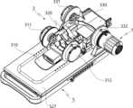
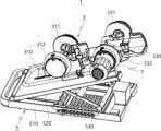
これらの図に示すように、本発明の一実施形態に係るリハビリ運動装置1は、リハビリ運動ユニット3と、リハビリ運動ユニット3を支持する載置台5を含む。 As shown in these drawings, a
リハビリ運動ユニット3は、手または足を支持する第1支持部310と、上肢の前腕または下肢の下腿を支持する第2支持部320と、第1支持部310と第2支持部320を回転可能に連結する一対の第1ヒンジ部311,312と、上肢の上腕または下肢の大腿を支持する第3支持部330と、第2支持部320と第3支持部330を回転可能に連結する一対の第2ヒンジ部331,332を含むことができる。 The
載置台5は、ベースプレート510と、リハビリ運動ユニット3が載置される載置プレート520を含む。ベースプレート510と載置プレート520は、水平方向の動きを垂直方向の動きに変換するリンクメカニズム(Link-mechanism)が適用されるのに、載置プレート520の一側がベースプレート510の板面に沿って水平移動可能に設置され、載置プレート520の中間領域がリンク部材530の一側に連結され、リンク部材530の他側がベースプレート510に回転可能に設けられることにより、リンクメカニズム(Link-mechanism)が適用される。 The mounting table 5 includes a
前記のような構成に応じて、図1に示すように、載置プレート520がベースプレート510に折りまれた状態において、図3に示すように、上肢のリハビリ訓練が行なえて、図2に示すように、リンクメカニズムにより載置プレート520をベースプレート510から一定の角度で起立させた状態で、図4に示すように、下肢のリハビリ訓練が行なえる。 According to the above-described configuration, as shown in FIG. 1, with the mounting
ここで、載置プレート520とベースプレート510との間の角度調整と、角度の固定及び固定解除については後述する。 The adjustment of the angle between the mounting
本発明に係るリハビリ運動ユニット3は、上肢または下肢での使用、リハビリ対象者の上肢の長さや下肢の長さに応じて調節できるように、第2支持部320の長さを調節して、第1支持部310と第3支持部330の間の間隔を調節する間隔調節部を含む。 The
図5乃至図8を参照して、本発明に係るリハビリ運動ユニット3の間隔調節部を説明する。 5 to 8, the interval adjuster of the
本発明に係るリハビリ運動ユニット3は、積層式スライドクランク(Slide-crank)の構造が第2支持部320に適用され、上肢の前腕または下肢の下腿を支持する第2支持部320の長さが調節されることを例にする。 In the
第2支持部320は、第1固定プレート322と、第2固定プレート323と、第1移動プレート324と、第2移動プレート325及びヒンジ軸部321を含むことができる。 The
第1固定プレート322は、一対の第1ヒンジ部311,312に連結されて、第1支持部310と回転可能に結合する。第2固定プレート323は、一対の第2ヒンジ部331,332と連結されて第3支持部330と回転可能に結合する。 The
第1移動プレート324は、第1固定プレート322とヒンジ軸部321との間に設けられ、往復移動する。 The first moving
第2移動プレート325は、第2固定プレート323とヒンジ軸部321との間に設けられ、往復移動する。 The second moving
ヒンジ軸部321は、第1固定プレート322と第2固定プレート323との間に設けられる。 The
一方、間隔調節部は、第1クランク部326と第2クランク部327を含む。 On the other hand, the gap adjusting part includes a first crank
第1クランク部326は、第1固定プレート322とヒンジ軸部321に回転可能に連結されて、ヒンジ軸部321の回転運動を第1固定プレート322の直線運動に変換する。 The
第1クランク部326は、第1調節リンク326aと、第2調節リンク326bと、第1連結リンク326cを含む。 The
第1調節リンク326aは、ヒンジ軸部321に回転可能に結合される。 The
第2調節リンク326bは、一側が第1調節リンク326aに回転可能に結合され、他側が第1固定プレート322に回転可能に結合される。 The
第1連結リンク326cは、第1移動プレート324と、第1調節リンク326aの中間領域に回転可能に結合される。 The first connecting
第2クランク部327は、第2固定プレート323とヒンジ軸部321に回転可能に連結されて、ヒンジ軸部321の回転運動を第2固定プレート323の直線運動に変換する。 The
第2クランク部327は、第3調節リンク327aと、第4調節リンク327bと、第2連結リンク327cを含む。 The
第3調節リンク327aは、ヒンジ軸部321に回転可能に結合される。第3調節リンク327aは、第1調節リンク326aに対して180度の角度を置いて対向配置される。 The
第4調節リンク327bは、一側が第3調節リンク327aに回転可能に結合され、他側が第2固定プレート323に回転可能に結合される。第4調節リンク327bは、第2調節リンク326bと相反するように配置される。 One side of the
第2連結リンク327cは、第2移動プレート325と第3調節リンク327aの中間領域に回転可能に結合される。第2連結リンク327cは、第1連結リンク326cと相反するように配置される。 The second connecting
一方、第1移動プレート324は、第1固定プレート322から第1移動プレート324に向かって延びた一対の第1ガイド棒329aにより往復移動がガイドされる。また、第1移動プレート324は、ヒンジ軸部321から第1移動プレート324に向かって延びた一対の第3ガイド棒329cにより往復移動がガイドされる。ここで、本実施形態においては、第1ガイド棒329aと第3ガイド棒329cがそれぞれ、一対で備わることが図示されているが、これに限定されず、第1ガイド棒329aと第3ガイド棒329cはそれぞれ、一つ以上で備えられる。 On the other hand, the first moving
そして、第2移動プレート325は、第2固定プレート323から第2移動プレート325に向かって延びた一対の第2ガイド棒329bにより往復移動がガイドされる。また、第2移動プレート325は、ヒンジ軸部321から第2移動プレート325に向かって延びた一対の第3ガイド棒329cにより往復移動がガイドされる。ここで、本実施形態においては、第2ガイド棒329bと第3ガイド棒329cがそれぞれ、一対で備わることが図示されているが、これに限定されず、第2ガイド棒329bと第3ガイド棒329cはそれぞれ、一つ以上で備えられる。 The second moving
前記のような構成に応じて、本発明に係るリハビリ運動装置1の間隔調節部は、図7に示すように、第1固定プレート322及び第1移動プレート324と、第2固定プレート323及び第2移動プレート325がそれぞれ、ヒンジ軸部321を中心に相互接近または離隔するように連動して動作するスライドクランク(Slide-crank)のメカニズムが実装されて、第2支持部330の長さの調節が可能になり、第1支持部310と第3支持部330との間の間隔を調節することができる。 As shown in FIG. 7, the interval adjusting part of the
以下、本発明の理解を助けるために、図7を用いて、第2支持部330の長さの調節について具体的に説明する。 Hereinafter, adjustment of the length of the
図7において、第1調節リンク326aと第2調節リンク326bをヒンジ軸部321を中心にして時計廻りで旋回させると、第1調節リンク326aと第2調節リンク326bとの間の角度、第1調節リンク326aと第1連結リンク326cとの間の角度が増加し、ヒンジ軸部321と第1固定プレート322との間の間隔が大きくなる。同様に、第3調節リンク327aと第4調節リンク327bとの間の角度、第3調節リンク327aと第2連結リンク327cとの間の角度が第1調節リンク326aと第2調節リンク326bとの間の等しい大きさで増加し、ヒンジ軸部321と第2固定プレート323との間の間隔が大きくなる。これにより、第1固定プレート322と第2固定プレート323はそれぞれ、ヒンジ軸部321から等しい大きさで開くことになる。 In FIG. 7, when the
逆に、図7において、第1調節リンク326aと第2調節リンク326bをヒンジ軸部321を中心にして反時計廻りで旋回させると、第1調節リンク326aと第2調節リンク326bとの間の角度、第1調節リンク326aと第1連結リンク326cとの間の角度が減少し、ヒンジ軸部321と第1固定プレート322との間の間隔が小さくなる。同様に、第3調節リンク327aと第4調節リンク327bとの間の角度、第3調節リンク327aと第2連結リンク327cとの間の角度が第1調節リンク326aと第2調節リンク326bとの間の等しい大きさで減少し、ヒンジ軸部321と第2固定プレート323との間の間隔が小さくなる。これにより、第1固定プレート322と第2固定プレート323はそれぞれ、ヒンジ軸部321から等しい大きさで絞られることになる。 Conversely, in FIG. 7, when the
したがって、本発明に係るリハビリ運動装置1は、第1固定プレート322及び第1移動プレート324と、第2固定プレート323及び第2移動プレート325がヒンジ軸部321を中心に相互に接近または離隔するように連動して動作される。 Therefore, in the
一方、第1固定プレート322と第2固定プレート323は、一対の連結バー328により連結される。 Meanwhile, the
本発明においては、連結バー328の一側が第2固定プレート323に固定され、第1固定プレート322は連結バー328に移動可能に結合されて、第1固定プレート322は第2固定プレート323に接近及び離隔する。 In the present invention, one side of the connecting
第1固定プレート322には、連結バー328が通過する貫通孔322a(図8参照)が形成され、第1固定プレート322の長手方向への移動が案内されることができる。 The
そして、第1固定プレート322には、第1固定プレート322の長手方向への移動を断続する例えば、第1固定プレート322と第2固定プレート323の相対移動を制限する長さストッパー340が設けられる。本発明においては、長さストッパー340がそれぞれの連結バー328に一対で設けられることを例にする。 Further, the
図8は、本発明に係る長さストッパー340の領域の断面を示した図である。図8を参照して説明すれば、長さストッパー340は、断続レバー341と、押圧部材345を含むことができる。 FIG. 8 shows a cross-section in the area of the length stop 340 according to the invention. Referring to FIG. 8, the
断続レバー341は、第1固定プレート322に結合された回転軸322bに回転可能に設けられる。 The disconnecting
断続レバー341は、一端部に設けられ押圧部材345の押圧または押圧解除を行うプッシャー342と、他端部に設けられプッシャー342が押圧部材345の押圧または押圧解除を行うようにプッシャー342を回転させるためのハンドル343を含む。 The
プッシャー342は、一定の曲率半径を有する半円弧形状を有し、回転に応じて押圧部材345に接触及び離隔する。 The
したがって、図8で断続レバー341を回転軸322bを中心にして時計廻りで回転させると、プッシャーが押圧部材345に向かって回転して押圧部材352と接触し押圧部材345を押圧して、押圧部材345は貫通孔322aを通過する連結バー328を押圧して第1固定プレート322の長手方向への移動を防止する。一方、断続レバー341を回転軸322bを中心にして反時計廻りで回転させると、プッシャーが押圧部材345から離隔し押圧部材345の押圧解除を行って、貫通孔322aの内部で連結バー328の移動が可能になり、第1固定プレート322が連結バー328に沿って長手方向に移動可能になる。 Therefore, when the connecting/disconnecting
ここで、本実施形態においては、連結バー328の一側が第2固定プレート323に固定され、第1固定プレート322が連結バー328に移動可能に結合されることが示されているが、これに限定されず、連結バー328の一側が第1固定プレート322に固定され、第2固定プレート323が連結バー328に移動可能に結合されることもできる。この場合には、断続レバー341は第2固定プレート323に設けられる。 Here, in this embodiment, one side of the connecting
図9乃至図12は、本発明の他の実施形態に係る第2支持部330の長手方向への移動を断続する構造の例を示した図である。本発明の他の実施形態に係るリハビリ運動ユニット3は、ヒンジ軸部321に設けられ、第1固定プレート322と第2固定プレート323の相対移動を制限する回転ストッパー350を含むことができる。 9 to 12 are diagrams showing examples of structures for intermittently moving the
上述したように、本発明に係る第2支持部320は、長手方向への長さを調節するにおいて、スライドクランク(Slide-crank)の構造を有し、これはヒンジ軸部321の回転を含むのに、回転ストッパー350はヒンジ軸部321の回転を断続して一定の長さを保持する。 As described above, the
回転ストッパー350は、断続ダイヤル351と、ヒンジ軸部321を形成する軸本体353と、軸本体353から上向きに突出する軸柱部354と、軸柱部354を中心に回転し、第1調節リンク326a及び第3調節リンク327aが連結されて、第1調節リンク326a及び第3調節リンク327aを軸本体353に対して回転させる軸プレート352を含むことができる。 The
断続ダイヤル351は、断続ピン351aと係止溝351cを含む。 The
断続ピン351cは、軸本体353に向かう断続ダイヤル351の端部から突出して形成され、後述する複数の断続孔352aの中の選択されたいずれか一つの断続孔に挿入及び挿入解除を行う。 The connection/
係止溝351cは、断続ピン351aと離隔して軸本体353に向かう端部の一領域に陥没して形成される。本実施形態においては、一対の係止溝351cが対向して設けられている。 The locking
軸本体353には、軸柱部354の円周方向に沿って複数の断続孔352aが間隔を置いて形成されている。 A plurality of
軸プレート352は、円形のリング形状を有する。軸プレート352の外周には、第1調節リンク326a及び第3調節リンク327aが連結され、内周には、断続ダイヤル351が回転可能に設けられる。また、軸プレート352の内周の一領域には、断続ダイヤル351の係止溝351cに係止して断続ダイヤル351を軸プレート352に連結する一対の係止突起352bが突出して形成されている。
また、本発明に係る回転ストッパー350は、ストッパ用弾性部材355をさらに含むことができる。 Also, the
ストッパ用弾性部材355は、軸柱部354と断続ダイヤル351の間に設けられ、断続ピン351aが選択された断続孔352aに挿入されるように断続ダイヤル351に弾性力を発生する。 The stopper
ストッパ用弾性部材355は、ユーザーが第2支持部320の長さを調節するとき、断続ダイヤル351を引っ張って軸本体から上昇させて断続ピン351aを断続孔352aから離脱させた状態で長さを調節する途中に、第2支持部320が望む長さで調節される時に断続ダイヤル351を放すと、ストッパ用弾性部材355の弾性力により断続ダイヤル351が軸本体353に向かって下降し、同時に断続ピン351aが当該位置の断続孔352aに挿入される。 When the user adjusts the length of the
このような構成により、本発明に係る回転ストッパー350は、断続ピン351aが断続孔352aに挿入される場合に、軸プレート352は軸本体353に対して回転しないことにより、第2支持部320の長さは調節されない。同時に、軸プレート352の係止突起352bが断続ダイヤル351の係止溝351cに係止して、断続ダイヤルが軸柱部354を中心に回転することが防止される。 With this configuration, the
一方、本発明に係る回転ストッパー350は、断続ピン351aが断続孔352aからの挿入解除を行う場合に、軸プレート352は軸本体353に対して回転することにより、第2支持部320の長さは調節可能になる。この際に、軸プレート352の係止突起352bは、断続ダイヤル351の係止溝351cに係止状態を保持して、断続ダイヤル351は軸プレート352と連結された状態を保持する。これにより、断続ダイヤル351は、軸柱部354を中心に正逆回転可能になり、第1固定プレート322と第2固定プレート323は軸本体353を中心に相互に接近または離隔して第2支持部320の長さが調節できる。 On the other hand, in the
図11の未説明の参照符号351bは、断続ピン351aが挿入固定されるピン挿入部であり、参照符号351dは、軸柱部354が通過した後に固定される軸通過孔である。図10は、説明の便宜のために、断続ピン351aが断続ダイヤル351から抜けた状態で断続孔352aに挿入された状態を示す。 An unexplained reference numeral 351b in FIG. 11 is a pin insertion portion into which the
このように、第1固定プレート322及び第1移動プレート324と、第2固定プレート323及び第2移動プレート325がそれぞれ、ヒンジ軸部321を中心に相互に接近または離隔するように連動して動作するスライドクランク(Slide-crank)のメカニズムを実装することにより、第2支持部320の長さの調節が可能になり、ユーザーの様々な前腕または下腿の長さに対応し、第1支持部310と第3支持部330との間の間隔を調節して、リハビリ運動が行なえる。 In this way, the
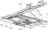
以下、図13乃至図20を参照して、本発明に係る載置台5の構成について詳細に説明する。 The configuration of the mounting table 5 according to the present invention will be described in detail below with reference to FIGS. 13 to 20. FIG.
上述したように、載置台5は、ベースプレート510と、載置プレート520と、リンク部材530を含むことができる。このような構成に応じて、図14に示すように、リンクメカニズム(Link-mechanism)が実装される。 As described above, mounting table 5 can include
前述したように、リンク部材530の両側はベースプレート510と載置プレート520に回転可能に結合される。ここで、載置プレート520の一側、すなわち、第1支持部510側の方向にベースプレート510の板面に沿って水平移動可能に設けられて、中間領域にリンク部材530の一側が回転可能に結合される。また、載置プレート520の他側はリンクメカニズム(Link-mechanism)によりベースプレート510に対して上下方向に接近及び離隔されることで、図1及び図2に示すように角度調整が可能になる。 As described above, both sides of the
リンク部材530の他側はベースプレート510に設けられる固定軸部531に回転可能に結合されることにより、載置プレート520の一側が水平移動する際にリンク部材530の両側の回転により載置プレート520の角度調整が可能になる。 The other side of the
一方、載置プレート520の両側には、一対の延長ブラケット521が第3支持部330に向かって並んで延びて設置される。一対の延長ブラケット521の一端部は、例えば、第1支持部310に向かう一端部は載置プレート520に回転可能に結合される。一対の延長ブラケット521の他端部は、例えば、第3支持部330に向かう他端部は連結棒522により連結される。 Meanwhile, on both sides of the mounting
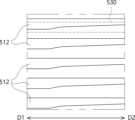
そして、ベースプレート510の内部には、載置プレート520とベースプレート510との間の角度に応じて連結棒522が係止する複数の係止爪512が長手方向に沿って形成された係止プレート511が設けられる。複数の係止爪512は、一対の延長ブラケット521の長手方向に沿って間隔を置いて形成され、連結棒522が選択的に係止する。これにより、載置プレート520とベースプレート510との間の傾斜角度に対応して、連結棒522が係止爪512の中のいずれか一つに係止した状態になって一定の角度で保持可能になる。 Inside the
また、本発明に係る載置台5は、連結棒522が係止爪512の中のいずれか一つに係止した状態が保持されるように固定する固定ユニット540を含むことができる。 In addition, the mounting table 5 according to the present invention may include a fixing
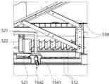
本発明の実施形態においては、ベースプレート510が、図15及び図16に示すように、複数の断続溝513a及び移動孔513bを含むことを例にする。 In an embodiment of the present invention, the
複数の断続溝513aは、それぞれの係止爪512に対応する位置にベースプレート510の一側の側面に陥没して形成される。すなわち、複数の断続溝513aは、延長ブラケット521の長手方向に沿って配列された係止爪512に対応して、ベースプレート510の一側の側面に長手方向に沿って一定の間隔を置いて配列して形成される。 A plurality of
移動孔513bは、それぞれの断続溝513aに形成されるのに、係止爪512に向かって貫通して形成される。つまり、移動孔513bは、断続溝513aが形成された位置でベースプレート510の板面が内部と外部を貫通するように形成される。 The moving
ここで、移動孔513bは、図16に示すように、上向き対角方向に開放される形態を有することで、以降で説明する固定ユニット510の延長ユニット542が移動孔513bの内部に挿入されたり離脱可能になる。 Here, as shown in FIG. 16, the moving
本発明の実施形態に係る固定ユニット540は、図17に示すように、延長ユニット542とユニット本体541を含むことができる。 A fixing
延長ユニット542は、一側が連結棒522に連結され、他側が移動孔513bを介してベースプレート510の外部へ延びる。本発明においては、図20に示すように、延長ユニット542の一側が中間板543を介して連結棒522に連結されることを例にするが、中間板543は連結棒522に直接締結されたり、連結棒522に連結されている延長ブラケット521に締結されたりして、連結棒522と連結することができる。 The
ユニット本体541は、延長ユニット542の他側に結合される。本発明においてはユニット本体541に延長ユニット542が挿入される挿入孔(図示せず)が形成されて、延長ユニット542が挿入孔に挿入されて相互結合することを例にする。 The
本発明の実施形態においては、ユニット本体541が断続溝513aに挿入される固定位置と断続溝513aから離脱される離脱位置との間を移動可能に延長ユニット542に結合することを例にする。このため、延長ユニット542には、図17に示すように、その長手方向に沿って一定の間隔を置いて一対の動作溝542bが形成されることを例にする。また、ユニット本体541には、ユニット本体541の固定位置と離脱位置でそれぞれ動作溝542bに係止する動作爪541cが形成されることを例にする。 In an embodiment of the present invention, the unit
本発明においては、動作爪541cが弾性的に動作溝542bの方向に挿入される形態で設けられ、ユーザーが離脱方向にユニット本体541を引っ張ると、内側の動作溝542bに係止されていた動作爪541cが係止解除され、外側の動作溝542bに係止するように構成することができる。同様に、ユーザーが固定方向にユニット本体541を押し込むと、外側の動作溝542bに係止されていた動作爪541cが係止解除され、外側の動作溝542bに係止することができる。 In the present invention, the
また、ユニット本体541は、固定位置と離脱位置で断続溝513aに挿入される挿入部541bと、ユーザーがユニット本体541を固定位置と離脱位置との間を移動させるために把持する把持部で構成されることができる。ここで、挿入部541bは、断続溝513aに挿入可能な大きさで備わって、移動孔513bの内側に移動せずに係止する大きさで備わることが望ましい。 In addition, the
前記のような構成に応じて、ユーザーがベースプレート510と載置プレート520との間の角度を調整しようとする場合、ユニット本体541が固定位置にある状態でハンドル部541aを引っ張って離脱位置に移動させると、ユニット本体541の挿入部541bが断続溝513aから抜け出す状態になる。 According to the above configuration, when the user wants to adjust the angle between the
このような状態で、ハンドル部541aを上部対角方向に移動させると、延長ユニット542に連結される連結棒522が係止爪512から離脱すると同時に、延長ユニット542が移動孔513bに沿って移動孔513bの外に出てくる状態になる。 In this state, when the
このような状態で載置プレート520の角度を調整しながら、その角度に対応する移動孔513bに延長ユニット542が挿入されるようにハンドル部541aを移動させると、延長ユニット542の挿入と同時に、連結棒522に当該係止爪512に挿入されて係止する状態になる。 While adjusting the angle of the mounting
前記のように角度調整が完了したら、ユニット本体541を再び押し込み、挿入部541bが断続溝513aに挿入される状態になると、挿入部541bが移動孔513b側に係止する状態になり、連結棒522が当該係止爪512に固定可能になる。 When the angle adjustment is completed as described above, the unit
一方、本発明の実施形態に係るそれぞれの係止爪512は、図18に示すように、連結棒522の長さに対応して延長ブラケット521の長手方向と交差する方向、すなわち、連結棒522の長手方向に延びて形成されることができる。 On the other hand, as shown in FIG. 18, each locking
そして、本発明の実施形態に係る係止爪512は、図18及び図19に示すように、固定ユニット540が設けられた方向、すなわち、図19のD1方向がその反対方向のD2方向より係止解除される方向に相対的にさらに突出するように設けられる。 18 and 19, the locking
前述したように、本発明の実施形態においては、固定ユニット540がベースプレート510の一側にのみ設けられることを例にしている。これにより、ユーザーが固定ユニット540を動かしながら、連結棒522を係止爪512から解除させる際には連結棒522の長さに応じて固定ユニット540側が解除方向にもう持ち上げられ、その反対方向には相対的に少し持ち上げられる。 As described above, in the embodiment of the present invention, the fixing
したがって、係止爪512の長さを図19に示すように、固定ユニット540方向の反対方向が相対的に少し突出するように形成することにより、固定ユニット540の操作を介して連結棒522を係止爪512から解除する際に、固定ユニット540が設けられた方向の係止解除が行われると、連結棒522の全体が係止爪512から係止解除されるように構成することができる。 Therefore, as shown in FIG. 19, the length of the locking
一方、本発明の実施形態に係る上肢及び下肢用リハビリ運動装置1は、図20に示すように、弾性ユニット522fをさらに含むことができる。 Meanwhile, the
弾性ユニット522fは、連結棒522が係止爪512に係止する方向に弾性を提供して、連結棒522がユーザーの操作なしに係止爪512から離脱することを防止することができる。たとえば、ユーザーが操作する過程や他の原因などにより、固定ユニット540のユニット本体541が離脱位置に位置する状態の際に、外部からの衝撃などで連結棒522が係止爪512から離脱すると、載置プレート520がベースプレート510方向に急速に折れる恐れがある。したがって、一定の衝撃にも連結棒522の離脱が遮断されることにより、不安全事故を未然に防止することができる。 The
また、固定ユニット540の操作の過程でも、連結棒522が係止爪512に挿入される方向に押圧される状態であるので、連結棒522の挿入位置で挿入方向に移動する力が生じ、より容易に連結棒522の係止爪512への挿入が可能になる。 Also, in the process of operating the fixing
図20を参照して、より具体的に説明すると、本発明の実施形態に係る載置プレート520は移動ブラケット526と、一対の載置ブラケット525及び載置部527を含むことができる。 More specifically, referring to FIG. 20, the mounting
移動ブラケット526は、ベースプレート510に沿って水平移動可能にベースプレート510に設けられる。そして、一対の載置ブラケット525は、移動ブラケット526の両側に回転可能に結合される。ここで、一対のリンク部材530がそれぞれ載置ブラケット525の中間領域に回転可能に結合することができる。載置部527は、移動ブラケット526と載置ブラケット525によって支持される板状に形成され、載置プレート520の上板を形成し、リハビリ運動ユニットが載置される。 A moving
ここで、延長ブラケット521は、移動ブラケット526の両側に回転可能に結合されて延長ブラケット521の移動に同期されて、移動ブラケット526が移動する。この際に、弾性ユニット522fは移動ブラケット526に設けられた状態で一対の延長ブラケット521の少なくとも一つを下部方向に押圧して延長ブラケット521に結合された連結棒522を係止爪512に係止する方向に押圧する。 Here, the
本発明においては、図20に示すように、弾性ユニット522fが板バネの形態で備わることを例にする。また、延長ブラケット521には、内側に延びたスカート部522dが設けられ、弾性ユニット522fがスカート部を押圧し延長ブラケット521を押圧することを例にしている。 In the present invention, as shown in FIG. 20, the
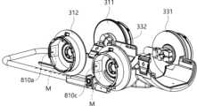
一方、本発明に係るリハビリ装置1は、駆動モジュール7を一対の第1ヒンジ部311,312と、一対の第2ヒンジ部331,332の中のいずれか一つに選択的に結合させることができる。上肢を例にして説明すると、第1ヒンジ部311,312の中のいずれか一側に駆動モジュール7を装着すると、手首のリハビリ運動が可能になり、第2ヒンジ部331,332の中のいずれか一側に駆動モジュール7を装着すると、肘関節のリハビリ運動が可能になる。 Meanwhile, in the
この際に、一対の第1ヒンジ部311,312の場合は、左側の上肢または右側の上肢のリハビリに応じて駆動モジュール7の装着位置を決定することができて、一対の第2ヒンジ部331,332の場合も同様に右側または左側の上肢のリハビリに応じて駆動モジュール7の選択が可能になる。 At this time, in the case of the pair of
以下、図21乃至図24を参照して、本発明に係る駆動モジュール7について詳細に説明する。 The
上述したように、駆動モジュール7は、一対の第1ヒンジ部311,312と、一対の第2ヒンジ部331,332の中のいずれか一つに選択的に装着されて、第1支持部310または第2支持部320を旋回させる。 As described above, the
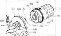
駆動モジュール7は、内部に駆動モータ、プリント回路基板などの構成要素が収容される本体ハウジング710と、駆動モータの回転軸が連結される駆動軸部材720と、第1ヒンジ部311,312または第2ヒンジ部331,332に装着及び固定するためのリング部材730を含むことができる。 The
そして、第1ヒンジ部311,312または第2ヒンジ部331,332には、リング結合部751が形成される。 A
一方、本実施形態においては、駆動モジュール7が、図1において、第1支持部310から第3支持部330に見たとき、右側に位置する第2ヒンジ部332に取り付けられているので、以下、説明の便利上、右側に位置する第2ヒンジ部をライト第2ヒンジ部332と称して説明する。 On the other hand, in this embodiment, the
ここで、リング部材730の内側には、複数の装着突起731がリング部材730円周方向に沿って一定の間隔を置いて形成されており、ライト第2ヒンジ部332の開口の周囲には、駆動モジュール7のリング部材730が結合されるリング結合部751が設けられている。リング結合部751には、装着突起731に対応して複数の係止部753が形成されることができる。 Here, inside the
これにより、駆動モジュール7をライト第2ヒンジ部332に挿入した後、リング部材730を回転させると、装着突起731が回転して係止部753に係止することで、駆動モジュール7の離脱を防止することができる。 As a result, when the
また、本体ハウジング710には、リング部材730に挿入されてリング部材730の回転を断続する係止レバー740が形成され、リング部材730を回転させた後、係止レバー740を押してリング部材730に挿入させることで、リング部材730の回転を防止することができる。 In addition, the
一方、本発明の実施形態に係るライト第2ヒンジ部332には、図24に示すように、駆動モジュール7の回転軸に沿って貫通された回転軸孔3322aが形成されることができる。ここで、駆動モジュール7の駆動軸部材720は、ライト第2ヒンジ部332に装着される際に回転軸孔3322aを通過してライト第2ヒンジ部332に結合される。これにより、駆動モジュール7の動作に応じて駆動軸部材720が回転すると、第2支持部320が旋回する。 Meanwhile, as shown in FIG. 24 , the right
より具体的に説明すると、本発明の実施形態においては、第2支持部320は、図21に示すように、軸結合ブラケット3231と、駆動軸固定部材360を含むことを例にする。 More specifically, in an embodiment of the present invention, the
軸結合ブラケット3231は、駆動モジュール7の回転軸に向かって延びることができる。本発明の実施形態においては、図21に示すように、第2支持部320の第2固定プレート323から軸結合ブラケット3231が駆動モータの回転軸に向かって延びることを例にしている。 The
駆動軸固定部材360は、駆動モジュール7がライト第2ヒンジ部332に締結される際に、回転軸孔3322aを介して挿入された駆動軸部材720を軸結合ブラケット3231に固定させる。これにより、駆動モジュール7の駆動に応じて駆動軸部材720が回転すると、駆動軸部材720の回転に応じて軸結合ブラケット3231が旋回して、第2支持部320全体が第3支持部330に対して旋回する。 The driving
本発明においては、駆動軸部材720の断面形状が多角形の断面形状を有することを例にしている。図21及び図23においては、駆動軸部材720の断面形状が六角形の断面形状を有することを例にしているが、本発明の技術的思想がこれに限定されない。 In the present invention, the cross-sectional shape of the
駆動軸部材720の断面形状に対応して、本発明の実施形態に係る駆動軸固定部材360は、図22に示すように、内径が多角形の断面形状を有する多角形の固定孔364を含むことがことができる。前述したように、六角形の断面形状を有する駆動軸部材720に対応して多角形の固定孔364の内径も六角形の断面形状を有するように備わることができる。 Corresponding to the cross-sectional shape of the
図22を参照して、より具体的に説明すると、駆動軸固定部材360は、ブラケット締結部361及び一対の絞り部材362,363を含むことができる。 More specifically, with reference to FIG. 22, the drive
ブラケット締結部361は、 多角形の固定孔364を中心に一側に設けられ、軸結合ブラケット3231に締結されて、駆動軸固定部材360を軸結合ブラケット3231に固定する。The
一対の絞り部材362,363は、多角形の固定孔364を中心に他側に設けされるのに、相互に離隔された空間365が形成される。図22に示すように、一対の絞り部材362,363の間に多角形の固定孔364が形成され、駆動軸部材720が多角形の固定孔364に挿入された状態で、一対の絞り部材362,363との間の間隔を接近させて、多角形の固定孔364に挿入された駆動軸部材720を絞って固定する。 A pair of
図22に図示された実施形態においては、ブラケット締結部361から一対の絞り部材362,363が分岐される形態を有することを例にしているが、相互対称する2つの部材の一側を結合させてブラケット締結部361を形成して、他側は離隔した状態に保持させて、一対の絞り部材362,363を構成することができる。 In the embodiment shown in FIG. 22, a pair of
本発明の実施形態においては、ブラケット締結部361がボルトを用いた締結を通じて軸結合ブラケット3231に締結されることを例にする。このため、ブラケット締結部361には、複数のボルト締結孔366c、366dが形成されるのに、本発明においては2軸方向でボルトを用いた締結が行われることを例にする。つまり、軸結合ブラケット3231の板面に形成された結合孔3231aに締結される一対のボルト締結孔366cと、軸結合ブラケット3231の板面から略「門」形に延びた一対の延長部3234に形成された結合孔3234aに締結される一対のボルト締結孔366bを含むことを例にする。 In an embodiment of the present invention, the
また、一対の絞り部材362,363の中のいずれか一つは、他側に向かって貫通した第1絞り孔366aが形成され、一対の絞り部材362,363の中の他の一つは、第1絞り孔366aを通過した絞りボルト(図示せず)が締結されて、絞り部材362,363との間の間隔が調節される第2絞り孔(図示せず)が形成されることができる。 One of the pair of
一方、ライト第2ヒンジ部332は、第1回転部3322と第2回転部3321を含むことができる。 Meanwhile, the light
第1回転部3322は、駆動軸部材720の回転に応じてライト第2支持部320と同期されて回転する。そして、第2回転部3321は、第1回転部3322に対して自由回転可能に設けられるのに、第3支持部330に連結されて第3支持部330と共に回転する。ここで、第1回転部3322及び第2回転部3321は、回転軸孔3322aを中心に同軸で結合されることを例にする。 The first
本発明の実施形態においては、第1回転部3322が軸結合ブラケット3231と軸結合して駆動軸部材720の回転に同期され、第2回転部3321に対して相対回転することを例にする。 In an embodiment of the present invention, the first
図23は駆動軸固定部材360が除去された状態を示した図であり、図24は軸結合ブラケット3231が除去された状態を示した図である。 FIG. 23 shows a state in which the drive
図23及び図24を参照して説明すると、軸結合ブラケット3231は、ブラケット結合孔3232と、複数の回転同期孔3233をさらに含むことができる。 23 and 24, the
ブラケット結合孔3232は、回転軸孔3322aに対応して形成され、回転軸孔3322aを通過した駆動軸部材720が通過する。ブラケット結合孔3232を通過した駆動軸部材720は、駆動軸固定部材360によって固定されるのは上述した通りである。
回転同期孔3233は、ブラケット結合孔3232の外側に沿って板面が貫通して形成される。ここで、第1回転部3322は、図24に示すように、複数の回転同期突起3322bを含むことができる。これにより、軸結合ブラケット3231が第1回転部3322に締結される際にそれぞれの回転同期孔3233に回転同期突起3322bが挿入されるのに、駆動モジュール7の回転に応じて駆動軸部材720が回転する際に軸結合ブラケット3231の回転に同期され、第1回転部3322が回転可能になる。 The
図21乃至図24を参照して説明した駆動モジュール7と締結されて駆動するライト第2ヒンジ部332の構成は、他の一つの第2ヒンジ部331にも対称的に実装される。同様に、それぞれの第1ヒンジ部311,312にも同じメカニズムが適用されることができて、ただし、第1支持部と第2支持部320が適用され、第1支持部が駆動モジュール7の回転に応じて旋回する構成を有する。 The configuration of the light
以下、図25乃至図28を参照して、本発明の実施形態に係る回転断続部770について詳細に説明する。 Hereinafter, the rotation interrupter 770 according to the embodiment of the present invention will be described in detail with reference to FIGS. 25 to 28. FIG.
図1、図2及び図25に示すように、一対の第1ヒンジ部311,312及び一対の第2ヒンジ部331,332の中の駆動モジュールが設けられないところにはヒンジカバーが設けられる。図25乃至図28は、第1ヒンジ部311,312の中の右側方向の第1ヒンジ部311,312を示すものである。 As shown in FIGS. 1, 2 and 25, a hinge cover is provided where the driving module is not provided in the pair of
回転断続部770は、第1回転部3322、すなわち、第1支持部310または第2支持部320と共に回転する第1回転部3322と共に回転する回転ギアプレート776と、第2回転部3321に設けられるギア断続部材771を含むことができる。 The rotation interrupting part 770 is provided on the first
回転ギアプレート776の円周方向の末端にはギアが形成され、ギア断続部材771の末端にはギアに挿入可能なギヤ挿入部772が形成されることができる。これにより、ギア断続部材771をスライド移動させてギア挿入部772が回転ギアプレート776のギア内部に挿入される場合に、第1回転部3322の回転を断続することができる。 A gear may be formed at a circumferential end of the
ここで、回転断続部770は、両側に突出するが、弾性的に押圧することができる一対の断続爪774を含むことができる。そして、第2回転部3321の板面には、回転断続部770が上下方向に移動する際に、断続爪774の挿入される断続溝775が回転断続部770の両側にそれぞれ回転断続部770の移動方向に沿って一対ずつ形成されることができる。 Here, the rotation interrupting part 770 may include a pair of interrupting
このような構成により、図1に示すように、第2ヒンジ部331,332に駆動モジュール7を装着し、一対の第1ヒンジ部311,312にそれぞれギア断続部材771と回転ギアプレート776のギアの歯がかみ合うようにして、一対の第1ヒンジ部311,312が回転しないように行う場合に、第2支持部320は駆動モジュール7の回転力によって回転運動が行なえるが、第1支持部310は旋回運動が制限されて、ユーザーは手首の関節が動かない状態で肘関節の運動が行なえる。 With such a configuration, as shown in FIG. 1, the
また、他の実施形態として、第1ヒンジ部311,312に駆動モジュール7を装着し、一対の第2ヒンジ部331,332にそれぞれ、ギア断続部材771と回転ギアプレート776のギアの歯がかみ合うようにして一対の第2ヒンジ部331,332が回転しないように行う場合に、第1支持部310は駆動モジュール7の回転力によって回転運動が行なえるが、第2支持部320は旋回運動が制限されて、ユーザーは肘関節が動かない状態で手首の関節の運動が行なえる。 As another embodiment, the
前記のような構成は、第2ヒンジ部331,332にも同様に適用することができる。 The configuration as described above can be applied to the
図26は、本発明の他の実施形態に係る回転断続部770の構成を示した図である。 FIG. 26 is a diagram showing the configuration of a rotation interrupter 770 according to another embodiment of the present invention.
図27に図示された実施形態においては、回転断続部270の両側面に一対ずつの断続溝774aが形成され、第2回転部3321に設けられた断続棒775aが断続溝775に挿入される構造を有する。ここで、断続棒775aは、断続溝775に挿入される方向に弾性的に押圧するのに、例えば、バネの弾性力を介して断続溝775に挿入される方向に押圧する構成を有することができる。 In the embodiment shown in FIG. 27, a pair of
一方、本発明の実施形態に係る駆動モジュールは、図21及び図23に示すように、ギア突起を含むことができる。 Meanwhile, a drive module according to embodiments of the present invention may include gear protrusions, as shown in FIGS. 21 and 23 .
ここで、ギア突起はギア断続部材771が回転ギアプレート776にかみ合う位置でギア断続部材771に接触可能な位置に設けられる。これにより、ギア断続部材771が回転ギアプレート776とかみ合う状態、すなわち第1回転部3322と第2回転部3321が相対回転しない状態で駆動モジュールが第1ヒンジ部311,312または第2ヒンジ部331,332に締結されることを防止することができる。つまり、ギア断続部材771が回転ギアプレート776にかみ合う状態の際に駆動モジュールの締結が可能になると、第1回転部3322の回転が断続された状態で駆動モジュールが回転して、駆動モジュールの故障の原因となる可能性があるからである。 Here, the gear projection is provided at a position where the gear connection/
したがって、第1回転部3322の回転が断続された状態では、駆動モジュール自体が締結されないようにして、前記のような状況に応じた故障を防止することができる。 Therefore, when the rotation of the first
また、第1ヒンジ部311,312及び第2ヒンジ部331,332は、ギア断続部材771の動作に応じて現在の状態が表示される状態表示窓773が形成されることができる。つまり、ギア断続部材771が回転ギアプレートにかみ合う位置にある場合に状態表示窓773に「Lock」と表示され、かみ合い解除された状態の場合に状態表示窓773に「Unlock」と表示されるように備わることができる。これは器具的にギア断続部材771のスライド移動に同期され、前記文字が表示されるように実装されることができる。 Also, the first and
前記実施形態においては、ギア断続部材771が第2回転部3321に設けられ、回転ギアプレート776が第1回転部3322と共に回転するように設けられることを例にしているが、逆の場合にも適用が可能である。つまり、ギア断続部材771が第1回転部3322に設けられ、回転ギアプレート776が第2回転部3321と共に回転するように構成することができる。 In the above embodiment, the gear connecting/disconnecting
一方、本発明の一実施形態に係るリハビリ運動装置1は、運動しようとする上肢または下肢の位置に対応して、駆動モジュール7を各ヒンジ部に選択的に装着してリハビリ運動が行なえる。 On the other hand, the
例えば、駆動モジュール7がレフト第1ヒンジ部311またはレフト第2ヒンジ部331に装着される場合に、本発明の一実施形態に係るリハビリ運動装置1は、駆動モジュール7がユーザーの胴体と干渉せず、右側の上肢に着用して運動が行なえる。この際に、駆動モジュール7がレフト第1ヒンジ部311に装着されると、右側の手首の関節の運動が行なえて、駆動モジュール7がレフト第2ヒンジ部331に装着されると、右側の肘関節の運動が行なえる。 For example, when the
駆動モジュール7がライト第1ヒンジ部312またはライト第2ヒンジ部332に装着される場合に、本発明の一実施形態に係るリハビリ運動装置1は、駆動モジュール7がユーザーの胴体と干渉せず、左側の上肢に装着して運動が行なえる。この際に、駆動モジュール7がライト第1ヒンジ部312に装着されると、左側の手首の関節の運動が行なえ、駆動モジュール7がレフト第2ヒンジ部332に装着されると、左側の肘関節の運動が行なえる。 When the
ここで、本発明の実施形態に係る駆動モジュール7は、スマートフォンなどのスマートデバイスにインストールされたアプリとの連動が可能に設けられる。この際に、駆動モジュール7が第1ヒンジ部と第2ヒンジ部の中のどこに設けられたか、そして左と右の中のどちら側に設けられたかを駆動モジュール7が自動的に認知することができれば望ましい。 Here, the
そこで、本発明の実施形態に係る上肢及び下肢用リハビリ運動装置1は、駆動モジュール7が装着位置を自動的に検出するための装着位置検出部を含むことができる。 Therefore, the
装着位置検出部は一対の第1ヒンジ部331と一対の第2ヒンジ部331,332の中の駆動モジュール7が装着された位置を検出する。本発明の実施形態においては、装着位置検出部が被検出モジュールM、810a、810b、810c、810dと、センサモジュールHSを含むことを例にする。 The mounting position detector detects the position where the
被検出モジュールM、810a、810b、810c、810dは、一対の第1ヒンジ部331及び一対の第2ヒンジ部331,332にそれぞれ設けられる。また、センサモジュールHSは、駆動モジュール7に設けられ、第1ヒンジ部331と第2ヒンジ部331,332の中のいずれか一つに駆動モジュール7が装着される際に被検出モジュールM、810a、810b、810c、810dを認識する。 The modules to be detected M, 810a, 810b, 810c, 810d are provided on the pair of
ここで、第1ヒンジ部331と第2ヒンジ部331,332にそれぞれ設けられる被検出モジュールM、810a、810b、810c、810dは、相互に区別可能に設けられることにより、センサモジュールHSがこれを認識した際に、第1ヒンジ部331と第2ヒンジ部331,332の中のどこに駆動モジュール7が設けられたかを認識する。 Here, the modules to be detected M, 810a, 810b, 810c, and 810d respectively provided in the
図28及び図29は、本発明の一実施形態に係る装着位置検出部の構成の例を示した図である。本発明の実施形態に係るセンサモジュールHSはホールセンサを含むことを例にする。 28 and 29 are diagrams showing an example of the configuration of the mounting position detection section according to one embodiment of the present invention. The sensor module HS according to the embodiment of the present invention is exemplified to include a Hall sensor.
ホールセンサーは、図21に示すように、駆動モジュール7の本体ハウジング710の内部に設けられることを例にする。 For example, the Hall sensor is installed inside the
それぞれの被検出モジュールM、810a、810b、810c、810dは、磁石部材Mと、磁石孔810a、810b、810c、810dを含むことを例にする。磁石部材Mは、それぞれ、第1ヒンジ部331と第2ヒンジ部331,332に相互に対応する位置に内蔵されることができる。ここで、磁石部材Mが設けられる位置は、駆動モジュール7が第1ヒンジ部311,312または第2ヒンジ部331,332に装着される際にホールセンサーによって検出可能な位置に設けられる。 For example, each detected module M, 810a, 810b, 810c, 810d includes a magnet member M and
磁石孔810a、810b、810c、810dは、図28に示すように、磁石部材Mを外部に露出させるために、第1ヒンジ部311,312及び第2ヒンジ部331,332に形成される。ここで、それぞれの磁石孔810a、810b、810c、810dは、位置と大きさの中の少なくとも一つが異なるように設けられ、ホールセンサが磁石部材Mの磁場を検出する際に、それぞれの磁石孔810a、810b、810c、810dの位置及び大きさに応じて、他の特性の磁場を検出するようにして、駆動モジュール7の装着位置を認識可能にすることができる。
図29を参照して説明すれば、それぞれの第1ヒンジ部311,312及び第2ヒンジ部331,332に形成される4つの磁石孔810a、810b、810c、810dがホールセンサーの位置を中心に上部と下部に位置するように設けれる。例えば、右側の第1ヒンジ部312に形成された磁石孔810a、810b、810c、810dが810aであり、左側の第1ヒンジ部311に形成された磁石孔810a、810b、810c、810dが810bであり、右側の第2ヒンジ部332に形成された磁石孔810a、810b、810c、810dが810cであり、左側の第2ヒンジ部331に形成された磁石孔810a、810b、810c、810dが810dであるといえば、駆動モジュール7が装着される際に磁石孔810a、810b、810c、810dの位置に応じて異なる特性の磁場が検出されて、駆動モジュール7の装着位置を確認することができる。 Referring to FIG. 29, four
図29は、磁石孔810a、810b、810c、810dの位置と大きさが他の形態を有することを例にしているが、磁場特性の区別が可能な場合には、他の形態での構成も可能である。 FIG. 29 exemplifies that the positions and sizes of the
他の実施形態として、被検出モジュールM、810a、810b、810c、810dに当該位置に対する情報が埋め込まれた近距離通信、例えばRF、NFC基盤のタグを取り付けて、センサーモジュールHSにてタグに埋め込まれた情報を認識するリーダーが設けられる。 In another embodiment, a short-range communication, e.g., RF or NFC-based tag in which information about the position is embedded is attached to the modules M, 810a, 810b, 810c, and 810d to be detected, and the sensor module HS is embedded in the tag. A reader is provided to recognize the information received.
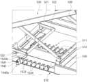
以下、図30乃至図32を参照して、本発明の他の実施形態に係る固定ユニット1540について説明する。 A
固定ユニット1540は、一対のユニット本体1541と、一対の動作レバー1542と、一対の連動レバー1543と、一対の連動ブラケット1522aを含むことができる。 The
ユニット本体1541は、ベースプレート510と載置プレート520の角度調整に応じて連結棒522と共に移動するのに、ベースプレート510に沿って往復移動する。 The
動作レバー1542はベースプレート510の外側に設けられ、ユニット本体1541に回転可能に結合される。 The
連動レバー1543はベースプレート510の内側に設けられ、動作レバー1542の回転に連動して回転するようにユニット本体1541に回転可能に結合される。
連動ブラケット1522aは、連結棒522の両側のエッジに連動レバー1543に向かって設けられ、連動レバー1543の回転に応じて押圧または押圧解除される。連動ブラケット1522aは連結ブラケット1522bによって連結棒522と連結される。 The interlocking
このような構成により、図32の(a)に示すように、動作レバー1542を時計廻りで回転させると、連動レバー1543が時計廻りで回転して、連結ブラケット1522bが連動レバー1543によって下部方向に押圧する形態になって、連結棒522が上部に動くことが遮断され、連結棒522がベースプレート510の係止爪512から抜けることを防止する。 With this configuration, as shown in FIG. 32(a), when the
一方、ベースプレート510に対する載置プレート520の角度を調整するために載置プレート520を折ったり広げたりする動作を行う際に、動作レバー1542を反時計廻りで回転させると、図32の(b)及び(c)に示すように、連動レバー1543が反時計廻りで回転しながら連動ブラケット1522aの上部の末端を持ち上げて、連結棒522が係止爪512から抜け出て、折ったり広げたりすることが可能になる。 On the other hand, in order to adjust the angle of the mounting
これにより、ベースプレート510の外部にある動作レバー1542の操作を介して連結棒522を係止爪512から抜いたり固定したりするように構成することにより、載置プレート520とベースプレート510との間に手を入れ連結棒522を持ち上げる動作により発生できる不安全事故を未然に防止することができる。 Accordingly, by operating the
また、連結棒522を係止爪512から係止解除して、図3に示すように載置プレート520がベースプレート510に折れた状態で上肢のリハビリ運動が行なえる。また、連結棒522を係止爪512に固定して、図4に示すように、載置プレート520をベースプレート510から一定の角度で起立させた状態で下肢のリハビリ運動が行なえる。 Further, the connecting
そして、リハビリ患者の状態に合わせて、床に安着されるベースプレート510に対する上肢または下肢の載置角度を簡便に調整してリハビリ運動が行なえる。 In addition, the rehabilitation exercise can be performed by simply adjusting the mounting angle of the upper or lower limb with respect to the
一方、図33及び図34には、前述した固定ユニット540、1540と他の形態の固定ユニット1540aが示されている。 Meanwhile, FIGS. 33 and 34 show the fixing
本発明の他の実施形態に係る固定ユニット1540aは、前述した固定ユニット540、1540と異なり、ベースプレート510の一側にベースプレート510の長手方向に沿って、例えば、複数の係止爪512と並んで複数の補助係止爪1523が形成されている。 A fixing
複数の補助係止爪1523は、溝と山をなす連続的な波形状を形成して、複数の係止爪512と等しいピッチを有する。複数の補助係止爪1523には、ユニット本体1541が選択的に載置される。 The plurality of
また、複数の補助係止爪1523が形成されたベースプレート510の一側には、補助係止爪1523の溝の位置に対応して複数の係止ピン1524が設けられている。 A plurality of locking
複数の係止ピン1524は、補助係止爪1523と等しいピッチを有して、ベースプレート510の一側から突出するように設けられている。 A plurality of locking
そして、本発明の他の実施形態に係る固定ユニット1540aは、動作レバー1542の回転に連動して回転する連動レバー1543aの自由端部が環形状を有する。 In addition, in the
連動レバー1543aは、ベースプレート510の外側に設けられ、ユニット本体1541に回転可能に結合される。
連動レバー1543aは、動作レバー1542の回転と連動して回転するのに伴い、選択された係止ピン1524に係止または係止解除される。 The interlocking
また、ユニット本体1541は、連結ブラケット1522bによって連結棒522に連結される。 Also, the unit
このような構成により、図33及び図34に示すように、連結棒522が係止爪512に係止した状態で動作レバー1542はベースプレート510に対して垂直に位置する。この際に、連動レバー1543aは、係止ピン1524に係止されて、連結棒522が上部に動くことが遮断され、連結棒522がベースプレート510の係止爪512から抜けることを防止する。 With such a configuration, as shown in FIGS. 33 and 34, the
一方、ベースプレート510に対する載置プレート520の角度を調整するために載置プレート520を折ったり広げたりする動作を行う際に、動作レバー1542を反時計廻りで回転させると、連動レバー1543aが反時計廻りで回転しながら係止ピン1524から係止解除され、これにより動作レバー1542を持ち上げて、連結棒522が係止爪512から抜け出て、折ったり広げたりすることが可能になる。 On the other hand, when the operation of folding or unfolding the mounting
これにより、ベースプレート510の外側にある動作レバー1542の操作を介して連結棒522を係止爪512から抜いたり固定したりするように構成することにより、リハビリ患者の状態に合わせて、床に安着されるベースプレート510に対する上肢または下肢の載置角度を簡便に調整してリハビリ運動が行なえる。 Accordingly, by operating the
以上、添付された図面を参照して、本発明の実施形態を説明したが、本発明が属する技術分野の通常の技術者は、本発明がその技術的思想や必須の特徴を変更せず、他の具体的な形態で実施されることができることを理解できるだろう。従って、以上で記述した実施形態は、すべての面で例示的なものであり、限定的ではないものと理解しなければならない。 The embodiments of the present invention have been described above with reference to the accompanying drawings. It will be understood that it can be embodied in other specific forms. Accordingly, the embodiments described above are to be considered in all respects as illustrative and not restrictive.
本発明は、患者の上肢または下肢のリハビリ運動のためのリハビリ運動装置に適用することができる。 INDUSTRIAL APPLICABILITY The present invention can be applied to a rehabilitation exercise device for rehabilitation exercise of a patient's upper limbs or lower limbs.
1:上肢及び下肢用リハビリ運動装置
3:リハビリ運動ユニット
5:載置台
7:駆動モジュール
310:第1支持部
311,312:第1ヒンジ部
320:第2支持部
330:第3支持部1: Rehabilitation Exercise Device for Upper and Lower Limbs 3: Rehabilitation Exercise Unit 5: Placement Table 7: Drive Module 310:
Claims (5)
Translated fromJapanese手または足を支持する第1支持部と、上肢の前腕または下肢の下腿を支持する第2支持部と、上肢の上腕または下肢の大腿を支持する第3支持部を含むリハビリ運動ユニットが載置して、一側が前記ベースプレートの板面に沿って水平移動可能に結合される載置プレートと、
両側がそれぞれ前記ベースプレートと前記載置プレートに回転可能に結合されて、前記載置プレートの一側が前記ベースプレートの板面に沿って水平移動する際に回転して、前記ベースプレートと前記載置プレートの角度を調整するリンク部材と、
前記載置プレートの一側に回転可能に結合され、前記第3支持部に向かって並んで延びた一対の延長ブラケットと、
前記一対の延長ブラケットを連結する連結棒と、
前記ベースプレートに前記一対の延長ブラケットの長手方向に沿って間隔を置いて形成され、前記ベースプレートと前記載置プレートとの間の傾斜角度に対応して前記連結棒が選択的に係止する複数の係止爪と、
前記連結棒が選択された前記係止爪に係止した状態が保持されるように固定する固定ユニットと、
前記連結棒が前記係止爪に係止されるように弾性力を提供する弾性ユニットと、を含み、
前記ベースプレートは、
それぞれの前記係止爪に対応する位置に、前記ベースプレートの一側の側面が陥没して形成された複数の断続溝と、
それぞれの前記断続溝に前記係止爪に向かって貫通して形成され、上向き対角方向に開放された移動孔を含み、
前記固定ユニットは、
一側が前記連結棒に連結され、他側が前記移動孔を介して前記ベースプレートの外部に延びる延長ユニットと、
前記延長ユニットの他側に結合されて、前記断続溝に挿入される固定位置と前記断続溝から離脱される離脱位置との間を移動可能に前記延長ユニットに結合されるユニット本体を含み、
前記ユニット本体の前記固定位置で前記延長ユニットの前記移動孔への移動が阻止され、前記連結棒が前記係止爪に係止する状態が保持され、
前記ユニット本体の前記離脱位置で前記延長ユニットが前記移動孔を介して他の移動孔への移動が可能になり、複数の前記係止爪の中のいずれか一つに選択的に前記連結棒が移動可能であり、
前記載置プレートは、
前記ベースプレートに沿って水平移動する移動ブラケットと、
前記移動ブラケットの両側に回転可能に結合される一対の載置ブラケットと、
前記移動ブラケットと前記載置ブラケットによって支持されて、前記リハビリ運動ユニットが載置される板状の載置部を含み、
一対の前記延長ブラケットが前記移動ブラケットに回転可能に結合され、前記延長ブラケットの移動に同期されて前記移動ブラケットが移動して、
前記弾性ユニットは前記移動ブラケットに設けられて一対の前記延長ブラケットの中の少なくとも一つを下部方向に押圧する板バネを含むことを特徴とする上肢及び下肢用リハビリ運動装置。a base plate;
Rehabilitation exercise unit including a first support for supporting the hand or foot, a second support for supporting the forearm of the upper leg or the lower leg of the lower leg, and a third support for supporting the upper arm of the upper leg or the thigh of the lower leg is placed. a mounting plate, one side of which is coupled to the base plate so as to be horizontally movable along the surface of the base plate;
Both sides are rotatably coupled to the base plate and the mounting plate, and one side of the mounting plate rotates when horizontally moving along the plate surface of the base plate, so that the base plate and the mounting plate are rotated. a link member for adjusting the angle;
a pair of extension brackets rotatably coupled to one side of the mounting plate and extending side by side toward the third support;
a connecting rod that connects the pair of extension brackets;
A plurality of plurality of extension brackets are formed on the base plate at intervals along the longitudinal direction of the pair of extension brackets, and the connecting rods are selectively engaged in correspondence with the inclination angle between the base plate and the mounting plate. a locking pawl;
a fixing unit that fixes the connecting rod so that it is held in a state of being locked to the selected locking pawl;
an elastic unit that provides an elastic force so that the connecting rod is locked to the locking pawl;
The base plate is
a plurality of intermittent grooves formed by recessing one side surface of the base plate at positions corresponding to the respective locking claws;
each of the intermittent grooves includes a moving hole penetrating toward the locking pawl and open diagonally upward;
The fixed unit is
an extension unit having one side connected to the connecting rod and the other side extending to the outside of the base plate through the moving hole;
a unit body connected to the other side of the extension unit and connected to the extension unit movably between a fixed position inserted into the intermittent groove and a disengaged position separated from the intermittent groove;
movement of the extension unit to the movement hole is blocked at the fixed position of the unit main body, and a state in which the connecting rod is locked to the locking claw is maintained;
At the disengaged position of the unit body, the extension unit can be moved through the moving hole to another moving hole, and the connecting rod can be selectively attached to any one of the plurality of locking claws. is movable, and
The mounting plate is
a moving bracket that moves horizontally along the base plate;
a pair of mounting brackets rotatably coupled to both sides of the moving bracket;
a plate-shaped mounting portion supported by the moving bracket and the mounting bracket and on which the rehabilitation exercise unit is mounted;
A pair of said extension brackets are rotatably coupled to said moving brackets, said moving brackets move in synchronization with the movement of said extension brackets,
The rehabilitation exercise device for upper and lower limbs, wherein the elastic unit includes a leaf spring installed on the movable bracket to press at least one of the pair of extension brackets downward.
前記ユニット本体は前記固定位置と前記離脱位置でそれぞれ前記動作溝に係止する動作爪を含むことを特徴とする請求項1に記載の上肢及び下肢用リハビリ運動装置。The extension unit has a pair of movement grooves formed at regular intervals along the longitudinal direction,
2. The rehabilitation exercise device for upper and lower limbs according to claim1 , wherein said unit body includes movement claws that are engaged with said movement grooves at said fixed position and at said disengaged position, respectively.
前記連結棒の長さに対応して前記長手方向と交差する方向に延びて形成され、かつ、前記交差する方向に関して前記固定ユニットが設けられた方向側の部分がその反対方向側の部分よりも係止解除される方向である前記長手方向の一方に向けてさらに突出し、かつ、前記固定ユニットの操作を介して前記連結棒を前記係止爪から解除する際に、前記固定ユニットが設けられた方向の係止が解除されると、前記連結棒全体が前記係止爪から係止解除されることを特徴とする請求項1に記載の上肢及び下肢用リハビリ運動装置。Each of the locking claws
It is formed to extend in a direction intersecting with the longitudinal direction corresponding to the length of the connecting rod, andthe portion on the side where the fixing unit is providedwith respect to the intersecting direction islarger than the portion on the opposite direction side. The fixingunit further protrudes in one of the longitudinal directions, which is the unlocking direction, and the fixing unit is provided when the connecting rod is released from the locking pawl through the operation of the fixing unit. 2. The rehabilitation exercise device for upper and lower limbs according to claim1, wherein the entireconnecting rod is unlocked from the locking pawl when the orientation is unlocked.
前記ベースプレートと前記載置プレートとの間の角度調整に応じて前記連結棒と共に前記ベースプレートに沿って往復移動する一対のユニット本体と、
前記ベースプレートの外側に設けられ、前記一対のユニット本体に回転可能に結合される一対の動作レバーと、
前記ベースプレートの内側に設けられ、前記一対の動作レバーの回転に連動して回転するように前記一対のユニット本体に回転可能に結合される一対の連動レバーと、
前記連結棒の両側のエッジに前記連動レバーに向かって設けられ、前記連動レバーの回転に応じて押圧または押圧解除される一対の連動ブラケットを含むことを特徴とする請求項1に記載の上肢及び下肢用リハビリ運動装置。The fixed unit is
a pair of unit bodies that reciprocate along the base plate together with the connecting rod according to the angle adjustment between the base plate and the mounting plate;
a pair of operating levers provided outside the base plate and rotatably coupled to the pair of unit bodies;
a pair of interlocking levers provided inside the base plate and rotatably coupled to the pair of unit bodies so as to rotate in conjunction with rotation of the pair of operating levers;
2. The upper limb according to claim1 , further comprising a pair of interlocking brackets provided on both edges of the connecting rod toward the interlocking lever and pressed or released according to rotation of the interlocking lever. Rehabilitation exercise device for lower extremities.
前記ベースプレートに前記複数の係止爪と並んで前記ベースプレートの長手方向に沿って連続的な波形状で形成された複数の補助係止爪と、
前記ベースプレートに前記補助係止爪と等しいピッチで設けられた複数の係止ピンと、
前記ベースプレートと前記載置プレートとの間の角度調整に応じて前記連結棒と共に前記ベースプレートに沿って往復移動し、前記複数の補助係止爪に選択的に載置されるユニット本体と、
前記ベースプレートの外側に設けられ、前記ユニット本体に回転可能に結合される動作レバーと、
前記ベースプレートの外側に設けられ、前記動作レバーの回転に連動して回転するように、前記ユニット本体に回転可能に結合され、前記複数の係止ピンに選択的に係止または係止解除される連動レバーを含むことを特徴とする請求項1に記載の上肢及び下肢用リハビリ運動装置。The fixed unit is
a plurality of auxiliary locking claws formed on the base plate in parallel with the plurality of locking claws and having a continuous wavy shape along the longitudinal direction of the base plate;
a plurality of locking pins provided on the base plate at the same pitch as the auxiliary locking claws;
a unit body that reciprocates along the base plate together with the connecting rod according to the angle adjustment between the base plate and the mounting plate and is selectively mounted on the plurality of auxiliary locking claws;
an operation lever provided outside the base plate and rotatably coupled to the unit body;
It is provided outside the base plate, is rotatably coupled to the unit body so as to rotate in conjunction with rotation of the operating lever, and is selectively locked or unlocked by the plurality of locking pins. The rehabilitation exercise device for upper and lower limbs according to claim1 , comprising an interlocking lever.
Applications Claiming Priority (9)
| Application Number | Priority Date | Filing Date | Title |
|---|---|---|---|
| KR1020190146775AKR102246049B1 (en) | 2019-11-15 | 2019-11-15 | Rehabilitation exercise apparatus for upper limb and lower limb |
| KR10-2019-0146775 | 2019-11-15 | ||
| KR10-2020-0022969 | 2020-02-25 | ||
| KR20200022969 | 2020-02-25 | ||
| KR10-2020-0043957 | 2020-04-10 | ||
| KR1020200043957AKR102352603B1 (en) | 2020-02-25 | 2020-04-10 | Rehabilitation exercise apparatus for upper limb and lower limb |
| KR1020200141795AKR102467495B1 (en) | 2020-10-29 | 2020-10-29 | Rehabilitation exercise apparatus for upper limb and lower limb |
| KR10-2020-0141795 | 2020-10-29 | ||
| PCT/KR2020/015124WO2021096130A1 (en) | 2019-11-15 | 2020-11-02 | Rehabilitation exercise device for upper and lower limbs |
Publications (2)
| Publication Number | Publication Date |
|---|---|
| JP2022521378A JP2022521378A (en) | 2022-04-07 |
| JP7256281B2true JP7256281B2 (en) | 2023-04-11 |
Family
ID=75912848
Family Applications (1)
| Application Number | Title | Priority Date | Filing Date |
|---|---|---|---|
| JP2021546867AActiveJP7256281B2 (en) | 2019-11-15 | 2020-11-02 | Rehabilitation exercise device for upper and lower limbs |
Country Status (4)
| Country | Link |
|---|---|
| US (1) | US11819469B2 (en) |
| EP (1) | EP3984508B1 (en) |
| JP (1) | JP7256281B2 (en) |
| WO (1) | WO2021096130A1 (en) |
Families Citing this family (62)
| Publication number | Priority date | Publication date | Assignee | Title |
|---|---|---|---|---|
| US11904202B2 (en) | 2019-03-11 | 2024-02-20 | Rom Technolgies, Inc. | Monitoring joint extension and flexion using a sensor device securable to an upper and lower limb |
| US11471729B2 (en) | 2019-03-11 | 2022-10-18 | Rom Technologies, Inc. | System, method and apparatus for a rehabilitation machine with a simulated flywheel |
| US11957960B2 (en) | 2019-05-10 | 2024-04-16 | Rehab2Fit Technologies Inc. | Method and system for using artificial intelligence to adjust pedal resistance |
| US11801423B2 (en) | 2019-05-10 | 2023-10-31 | Rehab2Fit Technologies, Inc. | Method and system for using artificial intelligence to interact with a user of an exercise device during an exercise session |
| US11957956B2 (en) | 2019-05-10 | 2024-04-16 | Rehab2Fit Technologies, Inc. | System, method and apparatus for rehabilitation and exercise |
| US12102878B2 (en) | 2019-05-10 | 2024-10-01 | Rehab2Fit Technologies, Inc. | Method and system for using artificial intelligence to determine a user's progress during interval training |
| US11904207B2 (en) | 2019-05-10 | 2024-02-20 | Rehab2Fit Technologies, Inc. | Method and system for using artificial intelligence to present a user interface representing a user's progress in various domains |
| US11433276B2 (en) | 2019-05-10 | 2022-09-06 | Rehab2Fit Technologies, Inc. | Method and system for using artificial intelligence to independently adjust resistance of pedals based on leg strength |
| US11833393B2 (en) | 2019-05-15 | 2023-12-05 | Rehab2Fit Technologies, Inc. | System and method for using an exercise machine to improve completion of an exercise |
| US11896540B2 (en) | 2019-06-24 | 2024-02-13 | Rehab2Fit Technologies, Inc. | Method and system for implementing an exercise protocol for osteogenesis and/or muscular hypertrophy |
| US12402804B2 (en) | 2019-09-17 | 2025-09-02 | Rom Technologies, Inc. | Wearable device for coupling to a user, and measuring and monitoring user activity |
| US11071597B2 (en) | 2019-10-03 | 2021-07-27 | Rom Technologies, Inc. | Telemedicine for orthopedic treatment |
| US11282608B2 (en) | 2019-10-03 | 2022-03-22 | Rom Technologies, Inc. | Method and system for using artificial intelligence and machine learning to provide recommendations to a healthcare provider in or near real-time during a telemedicine session |
| US11270795B2 (en) | 2019-10-03 | 2022-03-08 | Rom Technologies, Inc. | Method and system for enabling physician-smart virtual conference rooms for use in a telehealth context |
| US11915815B2 (en) | 2019-10-03 | 2024-02-27 | Rom Technologies, Inc. | System and method for using artificial intelligence and machine learning and generic risk factors to improve cardiovascular health such that the need for additional cardiac interventions is mitigated |
| US12154672B2 (en) | 2019-10-03 | 2024-11-26 | Rom Technologies, Inc. | Method and system for implementing dynamic treatment environments based on patient information |
| US11923065B2 (en) | 2019-10-03 | 2024-03-05 | Rom Technologies, Inc. | Systems and methods for using artificial intelligence and machine learning to detect abnormal heart rhythms of a user performing a treatment plan with an electromechanical machine |
| US11915816B2 (en) | 2019-10-03 | 2024-02-27 | Rom Technologies, Inc. | Systems and methods of using artificial intelligence and machine learning in a telemedical environment to predict user disease states |
| US11955222B2 (en) | 2019-10-03 | 2024-04-09 | Rom Technologies, Inc. | System and method for determining, based on advanced metrics of actual performance of an electromechanical machine, medical procedure eligibility in order to ascertain survivability rates and measures of quality-of-life criteria |
| US11978559B2 (en) | 2019-10-03 | 2024-05-07 | Rom Technologies, Inc. | Systems and methods for remotely-enabled identification of a user infection |
| US12230381B2 (en) | 2019-10-03 | 2025-02-18 | Rom Technologies, Inc. | System and method for an enhanced healthcare professional user interface displaying measurement information for a plurality of users |
| US11830601B2 (en) | 2019-10-03 | 2023-11-28 | Rom Technologies, Inc. | System and method for facilitating cardiac rehabilitation among eligible users |
| US12087426B2 (en) | 2019-10-03 | 2024-09-10 | Rom Technologies, Inc. | Systems and methods for using AI ML to predict, based on data analytics or big data, an optimal number or range of rehabilitation sessions for a user |
| US12246222B2 (en) | 2019-10-03 | 2025-03-11 | Rom Technologies, Inc. | Method and system for using artificial intelligence to assign patients to cohorts and dynamically controlling a treatment apparatus based on the assignment during an adaptive telemedical session |
| US12230382B2 (en) | 2019-10-03 | 2025-02-18 | Rom Technologies, Inc. | Systems and methods for using artificial intelligence and machine learning to predict a probability of an undesired medical event occurring during a treatment plan |
| US12062425B2 (en) | 2019-10-03 | 2024-08-13 | Rom Technologies, Inc. | System and method for implementing a cardiac rehabilitation protocol by using artificial intelligence and standardized measurements |
| US12380984B2 (en) | 2019-10-03 | 2025-08-05 | Rom Technologies, Inc. | Systems and methods for using artificial intelligence and machine learning to generate treatment plans having dynamically tailored cardiac protocols for users to manage a state of an electromechanical machine |
| US12224052B2 (en) | 2019-10-03 | 2025-02-11 | Rom Technologies, Inc. | System and method for using AI, machine learning and telemedicine for long-term care via an electromechanical machine |
| US12020799B2 (en) | 2019-10-03 | 2024-06-25 | Rom Technologies, Inc. | Rowing machines, systems including rowing machines, and methods for using rowing machines to perform treatment plans for rehabilitation |
| US11961603B2 (en) | 2019-10-03 | 2024-04-16 | Rom Technologies, Inc. | System and method for using AI ML and telemedicine to perform bariatric rehabilitation via an electromechanical machine |
| US11955220B2 (en) | 2019-10-03 | 2024-04-09 | Rom Technologies, Inc. | System and method for using AI/ML and telemedicine for invasive surgical treatment to determine a cardiac treatment plan that uses an electromechanical machine |
| US12420145B2 (en) | 2019-10-03 | 2025-09-23 | Rom Technologies, Inc. | Systems and methods of using artificial intelligence and machine learning for generating alignment plans to align a user with an imaging sensor during a treatment session |
| US20210134412A1 (en) | 2019-10-03 | 2021-05-06 | Rom Technologies, Inc. | System and method for processing medical claims using biometric signatures |
| US11265234B2 (en) | 2019-10-03 | 2022-03-01 | Rom Technologies, Inc. | System and method for transmitting data and ordering asynchronous data |
| US11087865B2 (en) | 2019-10-03 | 2021-08-10 | Rom Technologies, Inc. | System and method for use of treatment device to reduce pain medication dependency |
| US12347543B2 (en) | 2019-10-03 | 2025-07-01 | Rom Technologies, Inc. | Systems and methods for using artificial intelligence to implement a cardio protocol via a relay-based system |
| US20230245750A1 (en) | 2019-10-03 | 2023-08-03 | Rom Technologies, Inc. | Systems and methods for using elliptical machine to perform cardiovascular rehabilitation |
| US11515021B2 (en) | 2019-10-03 | 2022-11-29 | Rom Technologies, Inc. | Method and system to analytically optimize telehealth practice-based billing processes and revenue while enabling regulatory compliance |
| US11101028B2 (en) | 2019-10-03 | 2021-08-24 | Rom Technologies, Inc. | Method and system using artificial intelligence to monitor user characteristics during a telemedicine session |
| US11955223B2 (en) | 2019-10-03 | 2024-04-09 | Rom Technologies, Inc. | System and method for using artificial intelligence and machine learning to provide an enhanced user interface presenting data pertaining to cardiac health, bariatric health, pulmonary health, and/or cardio-oncologic health for the purpose of performing preventative actions |
| US12327623B2 (en) | 2019-10-03 | 2025-06-10 | Rom Technologies, Inc. | System and method for processing medical claims |
| US11075000B2 (en) | 2019-10-03 | 2021-07-27 | Rom Technologies, Inc. | Method and system for using virtual avatars associated with medical professionals during exercise sessions |
| US12020800B2 (en) | 2019-10-03 | 2024-06-25 | Rom Technologies, Inc. | System and method for using AI/ML and telemedicine to integrate rehabilitation for a plurality of comorbid conditions |
| US11139060B2 (en) | 2019-10-03 | 2021-10-05 | Rom Technologies, Inc. | Method and system for creating an immersive enhanced reality-driven exercise experience for a user |
| US12420143B1 (en) | 2019-10-03 | 2025-09-23 | Rom Technologies, Inc. | System and method for enabling residentially-based cardiac rehabilitation by using an electromechanical machine and educational content to mitigate risk factors and optimize user behavior |
| US11282599B2 (en) | 2019-10-03 | 2022-03-22 | Rom Technologies, Inc. | System and method for use of telemedicine-enabled rehabilitative hardware and for encouragement of rehabilitative compliance through patient-based virtual shared sessions |
| US12220201B2 (en) | 2019-10-03 | 2025-02-11 | Rom Technologies, Inc. | Remote examination through augmented reality |
| US11955221B2 (en) | 2019-10-03 | 2024-04-09 | Rom Technologies, Inc. | System and method for using AI/ML to generate treatment plans to stimulate preferred angiogenesis |
| US11069436B2 (en) | 2019-10-03 | 2021-07-20 | Rom Technologies, Inc. | System and method for use of telemedicine-enabled rehabilitative hardware and for encouraging rehabilitative compliance through patient-based virtual shared sessions with patient-enabled mutual encouragement across simulated social networks |
| US11887717B2 (en) | 2019-10-03 | 2024-01-30 | Rom Technologies, Inc. | System and method for using AI, machine learning and telemedicine to perform pulmonary rehabilitation via an electromechanical machine |
| US12100499B2 (en) | 2020-08-06 | 2024-09-24 | Rom Technologies, Inc. | Method and system for using artificial intelligence and machine learning to create optimal treatment plans based on monetary value amount generated and/or patient outcome |
| US11282604B2 (en) | 2019-10-03 | 2022-03-22 | Rom Technologies, Inc. | Method and system for use of telemedicine-enabled rehabilitative equipment for prediction of secondary disease |
| US11317975B2 (en) | 2019-10-03 | 2022-05-03 | Rom Technologies, Inc. | Method and system for treating patients via telemedicine using sensor data from rehabilitation or exercise equipment |
| US12427376B2 (en) | 2019-10-03 | 2025-09-30 | Rom Technologies, Inc. | Systems and methods for an artificial intelligence engine to optimize a peak performance |
| US12150792B2 (en) | 2019-10-03 | 2024-11-26 | Rom Technologies, Inc. | Augmented reality placement of goniometer or other sensors |
| US12176089B2 (en) | 2019-10-03 | 2024-12-24 | Rom Technologies, Inc. | System and method for using AI ML and telemedicine for cardio-oncologic rehabilitation via an electromechanical machine |
| US12191018B2 (en) | 2019-10-03 | 2025-01-07 | Rom Technologies, Inc. | System and method for using artificial intelligence in telemedicine-enabled hardware to optimize rehabilitative routines capable of enabling remote rehabilitative compliance |
| US11826613B2 (en) | 2019-10-21 | 2023-11-28 | Rom Technologies, Inc. | Persuasive motivation for orthopedic treatment |
| US12424319B2 (en) | 2019-11-06 | 2025-09-23 | Rom Technologies, Inc. | System for remote treatment utilizing privacy controls |
| EP3984512B1 (en)* | 2019-11-15 | 2025-01-08 | H Robotics Inc. | Upper and lower limb rehabilitation exercise apparatus |
| US11107591B1 (en) | 2020-04-23 | 2021-08-31 | Rom Technologies, Inc. | Method and system for describing and recommending optimal treatment plans in adaptive telemedical or other contexts |
| WO2021262809A1 (en) | 2020-06-26 | 2021-12-30 | Rom Technologies, Inc. | System, method and apparatus for anchoring an electronic device and measuring a joint angle |
Citations (3)
| Publication number | Priority date | Publication date | Assignee | Title |
|---|---|---|---|---|
| JP2002119555A (en) | 2000-10-13 | 2002-04-23 | Ribaafasshon:Kk | Rehabilitation apparatus |
| US20060240955A1 (en) | 2005-01-19 | 2006-10-26 | Pu Kwan C | Foot exercise device having tiltable platform |
| CN105107144A (en) | 2015-08-13 | 2015-12-02 | 南京小树林医疗科技有限公司 | Multi-station body functional rehabilitation training machine |
Family Cites Families (16)
| Publication number | Priority date | Publication date | Assignee | Title |
|---|---|---|---|---|
| US3297320A (en)* | 1963-09-10 | 1967-01-10 | Anarel Inc | Device for stretch exercising muscles |
| DE2004031C3 (en)* | 1970-01-29 | 1974-12-12 | Gebrueder Junghans Gmbh, 7230 Schramberg | Starting block for running competitions |
| US4549534A (en)* | 1983-01-13 | 1985-10-29 | Zagorski Joseph B | Leg exercise device |
| US4558692A (en)* | 1984-06-25 | 1985-12-17 | Greiner Donn B | Passive leg exerciser |
| US4974830A (en)* | 1989-01-19 | 1990-12-04 | Sutter Corporation | Continuous passive motion device |
| US4930497A (en)* | 1989-01-23 | 1990-06-05 | Toronto Medical Corp. | Apparatus for imparting continuous passive motion to a lower limb |
| JP3174807B2 (en)* | 1996-04-05 | 2001-06-11 | 株式会社エム・イー・システム | Joint continuous passive exercise training device |
| CA2239144A1 (en)* | 1998-06-08 | 1999-12-08 | Mission Sante Bois-Francs Inc. | Orthopedic exercisor |
| US8888723B2 (en)* | 2004-02-05 | 2014-11-18 | Motorika Limited | Gait rehabilitation methods and apparatuses |
| US7309320B2 (en)* | 2004-09-17 | 2007-12-18 | Ana-Tek, Llc | Apparatus and method for supporting and continuously flexing a jointed limb |
| KR100936621B1 (en)* | 2008-03-20 | 2010-01-13 | 경희대학교 산학협력단 | Leg exercise rehabilitation apparatus |
| KR101059828B1 (en)* | 2009-12-08 | 2011-08-29 | (주)케어테크 | Recovery device for fracture patients |
| KR101163903B1 (en) | 2010-08-13 | 2012-07-09 | 한국과학기술원 | Robot shoulder appratus for stroke patients rehabilitation |
| KR101459696B1 (en)* | 2013-04-16 | 2014-11-12 | (주)유에스 | Training device for legs |
| JP6757971B2 (en)* | 2016-11-11 | 2020-09-23 | 充宣 大平 | Lower limb joint exercise device |
| KR101939582B1 (en)* | 2017-11-10 | 2019-01-23 | 대한민국 | Support Apparatus for Rehabilitation Training Trunk of Human Body |
- 2020
- 2020-11-02JPJP2021546867Apatent/JP7256281B2/enactiveActive
- 2020-11-02EPEP20886356.3Apatent/EP3984508B1/enactiveActive
- 2020-11-02USUS17/059,404patent/US11819469B2/enactiveActive
- 2020-11-02WOPCT/KR2020/015124patent/WO2021096130A1/ennot_activeCeased
Patent Citations (3)
| Publication number | Priority date | Publication date | Assignee | Title |
|---|---|---|---|---|
| JP2002119555A (en) | 2000-10-13 | 2002-04-23 | Ribaafasshon:Kk | Rehabilitation apparatus |
| US20060240955A1 (en) | 2005-01-19 | 2006-10-26 | Pu Kwan C | Foot exercise device having tiltable platform |
| CN105107144A (en) | 2015-08-13 | 2015-12-02 | 南京小树林医疗科技有限公司 | Multi-station body functional rehabilitation training machine |
Also Published As
| Publication number | Publication date |
|---|---|
| WO2021096130A1 (en) | 2021-05-20 |
| EP3984508A4 (en) | 2023-08-16 |
| EP3984508A1 (en) | 2022-04-20 |
| US11819469B2 (en) | 2023-11-21 |
| JP2022521378A (en) | 2022-04-07 |
| US20220305328A1 (en) | 2022-09-29 |
| EP3984508B1 (en) | 2025-07-30 |
Similar Documents
| Publication | Publication Date | Title |
|---|---|---|
| JP7256281B2 (en) | Rehabilitation exercise device for upper and lower limbs | |
| JP7198364B2 (en) | Rehabilitation exercise device for upper and lower limbs | |
| JP7231752B2 (en) | Rehabilitation exercise device for upper and lower limbs | |
| JP7231750B2 (en) | Rehabilitation exercise device for upper and lower limbs | |
| JP7231751B2 (en) | Rehabilitation exercise device for upper and lower limbs | |
| JP7202474B2 (en) | Rehabilitation exercise device for upper and lower limbs | |
| US11819468B2 (en) | Rehabilitation exercise device for upper and lower limbs | |
| US20230346628A1 (en) | Rehabilitation exercise device for upper and lower limbs | |
| US20230346627A1 (en) | Rehabilitation exercise device for upper and lower limbs | |
| KR102469723B1 (en) | Rehabilitation exercise apparatus for upper limb and lower limb | |
| JP2023515036A (en) | Rehabilitation exercise device for upper and lower limbs | |
| KR102387577B1 (en) | Rehabilitation exercise apparatus for upper limb and lower limb | |
| KR102352603B1 (en) | Rehabilitation exercise apparatus for upper limb and lower limb | |
| KR102352602B1 (en) | Rehabilitation exercise apparatus for upper limb and lower limb | |
| KR102352604B1 (en) | Rehabilitation exercise apparatus for upper limb and lower limb | |
| KR20210108294A (en) | Rehabilitation exercise apparatus for upper limb and lower limb |
Legal Events
| Date | Code | Title | Description |
|---|---|---|---|
| A621 | Written request for application examination | Free format text:JAPANESE INTERMEDIATE CODE: A621 Effective date:20210810 | |
| A977 | Report on retrieval | Free format text:JAPANESE INTERMEDIATE CODE: A971007 Effective date:20220729 | |
| A131 | Notification of reasons for refusal | Free format text:JAPANESE INTERMEDIATE CODE: A131 Effective date:20220830 | |
| A521 | Request for written amendment filed | Free format text:JAPANESE INTERMEDIATE CODE: A523 Effective date:20221124 | |
| TRDD | Decision of grant or rejection written | ||
| A01 | Written decision to grant a patent or to grant a registration (utility model) | Free format text:JAPANESE INTERMEDIATE CODE: A01 Effective date:20230322 | |
| A61 | First payment of annual fees (during grant procedure) | Free format text:JAPANESE INTERMEDIATE CODE: A61 Effective date:20230330 | |
| R150 | Certificate of patent or registration of utility model | Ref document number:7256281 Country of ref document:JP Free format text:JAPANESE INTERMEDIATE CODE: R150 |