JP7255381B2 - hanging seat - Google Patents
hanging seatDownload PDFInfo
- Publication number
- JP7255381B2 JP7255381B2JP2019111464AJP2019111464AJP7255381B2JP 7255381 B2JP7255381 B2JP 7255381B2JP 2019111464 AJP2019111464 AJP 2019111464AJP 2019111464 AJP2019111464 AJP 2019111464AJP 7255381 B2JP7255381 B2JP 7255381B2
- Authority
- JP
- Japan
- Prior art keywords
- slings
- vehicle
- seat body
- occupant
- support member
- Prior art date
- Legal status (The legal status is an assumption and is not a legal conclusion. Google has not performed a legal analysis and makes no representation as to the accuracy of the status listed.)
- Active
Links
Images


Classifications
- B—PERFORMING OPERATIONS; TRANSPORTING
- B60—VEHICLES IN GENERAL
- B60N—SEATS SPECIALLY ADAPTED FOR VEHICLES; VEHICLE PASSENGER ACCOMMODATION NOT OTHERWISE PROVIDED FOR
- B60N3/00—Arrangements or adaptations of other passenger fittings, not otherwise provided for
- B60N3/008—Arrangements or adaptations of other passenger fittings, not otherwise provided for of beds
- B—PERFORMING OPERATIONS; TRANSPORTING
- B60—VEHICLES IN GENERAL
- B60N—SEATS SPECIALLY ADAPTED FOR VEHICLES; VEHICLE PASSENGER ACCOMMODATION NOT OTHERWISE PROVIDED FOR
- B60N2/00—Seats specially adapted for vehicles; Arrangement or mounting of seats in vehicles
- B60N2/70—Upholstery springs ; Upholstery
- B60N2/7011—Upholstery springs ; Upholstery of substantially two-dimensional shape, e.g. hammock-like, plastic shells, fabrics
- A—HUMAN NECESSITIES
- A45—HAND OR TRAVELLING ARTICLES
- A45F—TRAVELLING OR CAMP EQUIPMENT: SACKS OR PACKS CARRIED ON THE BODY
- A45F3/00—Travelling or camp articles; Sacks or packs carried on the body
- A45F3/22—Hammocks; Hammock spreaders
- A—HUMAN NECESSITIES
- A45—HAND OR TRAVELLING ARTICLES
- A45F—TRAVELLING OR CAMP EQUIPMENT: SACKS OR PACKS CARRIED ON THE BODY
- A45F3/00—Travelling or camp articles; Sacks or packs carried on the body
- A45F3/22—Hammocks; Hammock spreaders
- A45F3/24—Stands; Supports
Landscapes
- Engineering & Computer Science (AREA)
- Transportation (AREA)
- Mechanical Engineering (AREA)
- Aviation & Aerospace Engineering (AREA)
- Seats For Vehicles (AREA)
Description
Translated fromJapanese本明細書では、車内において吊り下げ保持される吊り型シートを開示する。 Disclosed herein is a suspended seat that is held suspended in a vehicle.
一般に、車両に搭載されるシートは、硬い骨格部材の表面を、クッション部材で覆った椅子状のものが広く知られている。しかし、こうした椅子状の車載シートでは、硬く重い骨格部材が必要であるため、どうしても大型で、重くなりやすかった。 In general, a seat mounted on a vehicle is widely known as a chair-like seat in which the surface of a hard frame member is covered with a cushion member. However, such a chair-like in-vehicle seat requires a hard and heavy frame member, so it tends to be large and heavy.
ここで、特許文献1には、三列シート車両で用いられるハンモック状カー用品が開示されている。このカー用品は、ロープ状の枠部の内側にネットを取り付け、さらに、枠部の前後に引っかけ部を設けた、ハンモックのような構成となっている。当該カー用品を使用する際には、中間シートをフラットに倒した上で、前側の引っかけ部を最前列シートのヘッドレストに、後側の引っかけ部を、最後列シートのヘッドレストに、それぞれ引っかけて当該カー用品を、ハンモックのように吊るして使用する。 Here,
かかる特許文献1のカー用品は、椅子状の車載シートに比べて大幅に軽量化できる。しかし、特許文献1のカー用品は、もっぱら車内で就寝する際に使用されるものであり、車両の走行時に乗員が着座するシートではない。また、特許文献1のカー用品では、枠部を吊り下げ保持する部材が、枠部の前後両側にしか存在しない。この場合、当該カー用品は、前後方向に延びる軸を中心とする回転(ロール運動)が生じやすくなり、乗員の姿勢を安定して保つことが難しい。 The car article of
そこで、本明細書では、乗員の姿勢を安定して保つとともに、軽量化が可能な車載の吊り型シートを開示する。 Accordingly, the present specification discloses a suspension-type vehicle-mounted seat capable of maintaining a stable posture of an occupant and reducing weight.
本明細書で開示する吊り型シートは、車両に搭載される吊り型シートであって、乗員を下側から支持するシート本体と、前記シート本体の前部を通るとともに、前後方向かつ上側に延びて、車内の構造物に取り付けられる1以上の前吊り具と、前記シート本体の後部を通るとともに、前後方向かつ上側に延びて、車内の構造物に取り付けられる1以上の後吊り具と、前記シート本体の両サイドを通るとともに、左右方向かつ上側に延びて、車内の構造物に取り付けられる2以上の横吊り具と、を備え、前記シート本体が、前記1以上の前吊り具と、前記1以上の後吊り具と、前記2以上の横吊り具と、で吊り下げ保持されており、前記1以上の前吊り具と、前記1以上の後ろ吊り具と、前記2以上の横吊り具と、はいずれも、前記車両の内部に位置し、前記2以上の横吊り具は、前記シート本体の両サイドそれぞれから左右方向外側または左右方向内側に延びて、車内の構造物に取り付けられ、前記1以上の前吊り具および前記1以上の後ろ吊り具は、車両前後方向に延びる弾性フレームに取り付けられており、前記弾性フレームは、車両前部に位置する前車軸および車両後部に位置する後車軸に接続されている、ことを特徴とする。A suspension-type seat disclosed in this specification is a suspension-type seat mounted on a vehicle, and includes a seat body that supports an occupant from below, and a seat body that passes through a front portion of the seat body and extends in the front-rear direction and upward. one or more front slings attached to a structure in the vehicle; one or more rear slings passing through the rear portion of the seat body and extending in the front-rear direction and upward to be attached to the structure in the vehicle; two or more lateral slings passing through both sides of the seat body, extending in the left-right direction and upward, and attached to a structure inside the vehicle, wherein the seat body includes the one or more front slings, the Suspended and held by one or more rear slings and two or more lateral slings, the one or more front slings, the one or more rear slings, and the two or more side slings and are positioned inside the vehicle, and the two or more horizontal suspension devices extend laterally outward or laterally inward from both sides of the seat body and are attached to a structure in the vehicle, The one or more front slings and the one or more rear slings are attached to an elastic frame extending in the longitudinal direction of the vehicle. characterized bybeing connected to an axle .
車内構造物に取り付けられる吊り具でシート本体を吊り下げ保持することで、シート本体の姿勢を維持するための骨格部材が不要となり、軽量化が可能となる。また、シート本体の前後両側に設けられた前吊り具および後吊り具に加えて、左右方向に延びる横吊り具を設けることで、シート本体の過度なロール運動を抑制でき、乗員の乗り心地を向上できる。 By suspending and holding the seat body with a hanging tool attached to the vehicle interior structure, a frame member for maintaining the posture of the seat body becomes unnecessary, and the weight can be reduced. In addition to the front and rear slings on both the front and rear sides of the seat body, horizontal slings that extend in the left-right direction suppress excessive roll motion of the seat body, improving passenger comfort. can improve.
この場合、前記シート本体は、少なくとも、前記乗員の少なくとも背部が載置される第一支持部材と、前記乗員の少なくとも臀部が載置される第二支持部材と、に分割されていてもよい。 In this case, the seat body may be divided into at least a first support member on which at least the back of the occupant is placed, and a second support member on which at least the buttocks of the occupant are placed.
かかる構成とすることで、背部を含む上半身の動きと、臀部を含む乗員の下半身の動きを分けることができ、上半身および下半身それぞれの動きを別個に調整することができる。 With such a configuration, the movement of the upper body including the back and the movement of the occupant's lower body including the buttocks can be separated, and the movements of the upper body and the lower body can be adjusted separately.
この場合、前記第一支持部材は、複数のワイヤを網状に組み合わせて構成され、前記乗員の少なくとも背部が載置されるネット部材を含んでもよい。 In this case, the first support member may include a net member configured by combining a plurality of wires in a net shape, and on which at least the back of the occupant is placed.
かかる構成とすることで、ネット部材が、乗員の体格に応じて柔軟に変形するため、乗員の体格が異なる場合でも、乗員を適切に支持できる。 With this configuration, the net member deforms flexibly according to the physique of the occupant, so that the occupant can be appropriately supported even if the occupant has a different physique.
また、本明細書で開示する他の吊り型シートは、車両に搭載される吊り型シートであって、乗員を下側から支持するシート本体と、前記シート本体の前部を通るとともに、前後方向かつ上側に延びて、車内の構造物に取り付けられる1以上の前吊り具と、前記シート本体の後部を通るとともに、前後方向かつ上側に延びて、車内の構造物に取り付けられる1以上の後吊り具と、前記シート本体の両サイドを通るとともに、左右方向かつ上側に延びて、車内の構造物に取り付けられる2以上の横吊り具と、を備え、前記シート本体が、前記1以上の前吊り具と、前記1以上の後吊り具と、前記2以上の横吊り具と、で吊り下げ保持されており、前記1以上の前吊り具と、前記1以上の後ろ吊り具と、前記2以上の横吊り具と、はいずれも、前記車両の内部に位置し、前記シート本体は、少なくとも、前記乗員の少なくとも背部が載置される第一支持部材と、前記乗員の少なくとも臀部が載置される第二支持部材と、に分割されており、前記第一支持部材は、複数のワイヤを網状に組み合わせて構成され、前記乗員の少なくとも背部が載置されるネット部材を含み、前記第一支持部材の両サイドから前記横吊り具が延びる一方で、前記第二支持部材から延びる前記横吊り具がない、ことを特徴とする。Another suspension-type seat disclosed in this specification is a suspension-type seat mounted on a vehicle, and includes a seat body that supports an occupant from below, and a seat body that passes through the front portion of the seat body and extends in the front-rear direction. One or more front slings that extend upward and are attached to the structure inside the vehicle, and one or more rear slings that pass through the rear portion of the seat body and extend longitudinally and upward and are attached to the structure inside the vehicle. and two or more lateral slings that pass through both sides of the seat body, extend in the left-right direction and upward, and are attached to structures in the vehicle, wherein the seat body is attached to the one or more front slings. , the one or more rear slings, and the two or more lateral slings, and the one or more front slings, the one or more rear slings, and the two or more are positioned inside the vehicle, and the seat body includes at least a first support member on which at least the back of the occupant is placed, and at least the buttocks of the occupant are placed. and a second support member, wherein the first support member includes a net member configured by combining a plurality of wires in a net shape, on which at least the back of the occupant is placed, and the first support The lateral hangers extend from both sides of the member, while the lateral hangersdo not extend from the second support member.
かかる構成とした場合、第二支持部材は、第一支持部材に比べてロール運動しやすくなる。その結果、車両を通じて路面から入力される振動を、下半身のロール運動で吸収でき、上半身の位置および姿勢をより安定させることができる。 With such a configuration, the second support member rolls more easily than the first support member. As a result, vibrations input from the road surface through the vehicle can be absorbed by the roll motion of the lower body, and the position and posture of the upper body can be stabilized.
また、本明細書で開示する他の吊り型シートは、車両に搭載される吊り型シートであって、乗員を下側から支持するシート本体と、前記シート本体の前部を通るとともに、前後方向かつ上側に延びて、車内の構造物に取り付けられる1以上の前吊り具と、前記シート本体の後部を通るとともに、前後方向かつ上側に延びて、車内の構造物に取り付けられる1以上の後吊り具と、前記シート本体の両サイドを通るとともに、左右方向かつ上側に延びて、車内の構造物に取り付けられる2以上の横吊り具と、を備え、前記シート本体が、前記1以上の前吊り具と、前記1以上の後吊り具と、前記2以上の横吊り具と、で吊り下げ保持されており、前記シート本体は、少なくとも、前記乗員の少なくとも背部が載置される第一支持部材と、前記乗員の少なくとも臀部が載置される第二支持部材と、に分割されており、前記第一支持部材は、複数のワイヤを網状に組み合わせて構成され、前記乗員の少なくとも背部が載置されるネット部材を含み、前記第一支持部材の両サイドおよび前記第二支持部材の両サイドそれぞれから前記横吊り具が延びていてもよい。Another suspension-type seat disclosed in this specification is a suspension-type seat mounted on a vehicle, and includes a seat body that supports an occupant from below, and a seat body that passes through the front portion of the seat body and extends in the front-rear direction. One or more front slings that extend upward and are attached to the structure inside the vehicle, and one or more rear slings that pass through the rear portion of the seat body and extend longitudinally and upward and are attached to the structure inside the vehicle. and two or more lateral slings that pass through both sides of the seat body, extend in the left-right direction and upward, and are attached to structures in the vehicle, wherein the seat body is attached to the one or more front slings. The seat main body is a first support member on which at least the back of the occupant is placed. and a second support member on which at least the buttocks of the occupant are placed, and the first support member is configured by combining a plurality of wires in a net shape, and on which at least the back of the occupant is placed. The horizontal slings may extend from both sides of the first support memberand both sides of the second support member, respectively.
かかる構成とすることで、上半身だけでなく下半身のロール運動も抑制できる。 With such a configuration, not only the upper body but also the lower body roll motion can be suppressed.
また、本明細書で開示する他の吊り型シートは、車両に搭載される吊り型シートであって、乗員を下側から支持するシート本体と、前記シート本体の前部を通るとともに、前後方向かつ上側に延びて、車内の構造物に取り付けられる1以上の前吊り具と、前記シート本体の後部を通るとともに、前後方向かつ上側に延びて、車内の構造物に取り付けられる1以上の後吊り具と、前記シート本体の両サイドを通るとともに、左右方向かつ上側に延びて、車内の構造物に取り付けられる2以上の横吊り具と、を備え、前記シート本体が、前記1以上の前吊り具と、前記1以上の後吊り具と、前記2以上の横吊り具と、で吊り下げ保持されており、さらに、前記シート本体に取り付けられ、吊り具の始点が係合可能な係合部を有する基準プレートを備え、前記1以上の後吊り具のうち少なくとも一つ、および、前記2以上の横吊り具のうち少なくとも二つ、それぞれの始点が、前記基準プレートの前記係合部に係合されてもよい。Another suspension-type seat disclosed in this specification is a suspension-type seat mounted on a vehicle, and includes a seat body that supports an occupant from below, and a seat body that passes through the front portion of the seat body and extends in the front-rear direction. One or more front slings that extend upward and are attached to the structure inside the vehicle, and one or more rear slings that pass through the rear portion of the seat body and extend longitudinally and upward and are attached to the structure inside the vehicle. and two or more lateral slings that pass through both sides of the seat body, extend in the left-right direction and upward, and are attached to structures in the vehicle, wherein the seat body is attached to the one or more front slings. an engaging portion that is suspended and held by a sling, the one or more rear slings, and the two or more side slings, and is attached to the seat body and engageable with the starting points of the slings; at least one of the one or more rear slings and at least two of the two or more side slings, each starting point of which is engaged with the engaging portion of the reference plate. may be combined.
かかる基準プレートを設けることで、後吊り具および前吊り具の位置決めが容易となる。また、後吊り具および前吊り具の始点が、同じ基準プレートにあることで、シート本体が、この基準プレートを基準として安定して吊り下がる。結果として、乗員の乗り心地を向上できる。
また、本明細書で開示する他の吊り型シートは、車両に搭載される吊り型シートであって、乗員を下側から支持するシート本体と、前記シート本体の前部を通るとともに、前後方向かつ上側に延びて、車内の構造物に取り付けられる1以上の前吊り具と、前記シート本体の後部を通るとともに、前後方向かつ上側に延びて、車内の構造物に取り付けられる1以上の後吊り具と、前記シート本体の両サイドを通るとともに、左右方向かつ上側に延びて、車内の構造物に取り付けられる2以上の横吊り具と、を備え、前記シート本体が、前記1以上の前吊り具と、前記1以上の後吊り具と、前記2以上の横吊り具と、で吊り下げ保持されており、前記1以上の前吊り具と、前記1以上の後ろ吊り具と、前記2以上の横吊り具と、はいずれも、前記車両の内部に位置し、前記シート本体は、少なくとも、前記乗員の少なくとも背部が載置される第一支持部材と、前記乗員の少なくとも臀部が載置される第二支持部材と、に分割されており、前記第二支持部材は、前記第一支持部材に、部分的にのみ直接繋がっていることを特徴とする。By providing such a reference plate, the positioning of the rear sling and the front sling is facilitated. In addition, since the starting points of the rear sling and the front sling are on the same reference plate, the sheet body is stably suspended on the basis of this reference plate. As a result, the passenger's riding comfort can be improved.
Another suspension-type seat disclosed in this specification is a suspension-type seat mounted on a vehicle, and includes a seat body that supports an occupant from below, and a seat body that passes through the front portion of the seat body and extends in the front-rear direction. One or more front slings that extend upward and are attached to the structure inside the vehicle, and one or more rear slings that pass through the rear portion of the seat body and extend longitudinally and upward and are attached to the structure inside the vehicle. and two or more lateral slings that pass through both sides of the seat body, extend in the left-right direction and upward, and are attached to structures in the vehicle, wherein the seat body is attached to the one or more front slings. , the one or more rear slings, and the two or more lateral slings, and the one or more front slings, the one or more rear slings, and the two or more are positioned inside the vehicle, and the seat body includes at least a first support member on which at least the back of the occupant is placed, and at least the buttocks of the occupant are placed. and a second support member, said second support memberbeing directly connected to saidfirst support member only partially.
また、本明細書で開示する車両は、弾性を有した車両の骨格である弾性フレームであって、車両の前後方向に延びるとともに、上方に凸状に湾曲した弾性フレームと、前記弾性フレームの前部に連結された前部車体部材と、前記弾性フレームの後部に連結された後部車体部材と、前記前部車体部材と前記後部車体部材との間であって、前記弾性フレームの下方に配されるバッテリと、乗員の少なくとも背部を下側から支持するシート本体と、前記シート本体を吊り下げ保持する複数の吊り具であって、少なくとも一部が前記弾性フレームに取り付けられている複数の吊り具と、を備えることを特徴とする。 Further, the vehicle disclosed in the present specification includes an elastic frame that is a skeleton of the vehicle having elasticity, and includes an elastic frame that extends in the front-rear direction of the vehicle and curves upward in a convex shape; a front vehicle body member connected to the rear part of the elastic frame; a rear vehicle body member connected to the rear part of the elastic frame; a seat body that supports at least the back of an occupant from below; and a plurality of suspension fixtures that suspend and hold the seat body, at least a portion of which is attached to the elastic frame. and.
本明細書で開示する車載の吊り型シートによれば、乗員の姿勢を安定して保つとともに、軽量化が可能である。 According to the vehicle-mounted hanging-type seat disclosed in this specification, it is possible to keep the occupant's posture stable and to reduce the weight.
以下、図面を参照して吊り型シート11の構成について説明する。なお、以下の説明において、特に明記しない限り、「前方」および「後方」は、吊り型シート11に横たわる乗員100からみて「水平方向足先側」および「水平方向頭側」のことである。同様に、「右方向」および「左方向」も特に明記しない限り、水平方向右手側および水平方向左手側を意味している。そして、「上下方向」とは、前後方向および左右方向に直交する方向のことである。また、各図において、「Fr」、「Up」、「R」は、それぞれ、上記の前方、上方、右方向を示している。 The configuration of the hanging
吊り型シート11の説明に先だって、まず、この吊り型シート11が搭載される車両について図1から図3を参照して説明する。図1は、吊り型シート11が搭載される車両10の概略平面図であり、図2は、車両10の概略側面図である。また、図3は、車両10に搭載される弾性フレーム22の概略斜視図である。この車両は、1人乗り用の小型車両である。車両10は、動力源としてモータ(図示せず)を備えた電動車両である。また、この車両10は、乗員100が全ての動的運転タスクを実行する非自動運転車両でもよいし、一部または全ての動的運転タスクを自動で行う運転支援車両または自動運転車両でもよい。 Before describing the
車両10は、船を天地反転させたような形状のボディ12(図1、図2では、ボディ外形を二点鎖線で図示)を有している。後述する吊り型シート11(図1では図示せず)は、その前後方向が、車両前後方向と平行になる姿勢で設置される。車両10の内部には、車幅方向中心位置において車両前後方向に延びる弾性フレーム22が配置されている。この弾性フレーム22は、図2に示す通り、側面視では、上方に凸となるような略弧状となっている。また、弾性フレーム22の前部および後部は、いずれも車幅方向に二又に分かれている。以下では、前側の二又部分を「前側二又部22f」、後側の二又部分を「後側二又部22r」と呼ぶ。この弾性フレーム22は、適度な弾性を有しており、車両走行時に路面から入力される振動の一部が、当該弾性フレーム22の弾性変位により吸収される。このような弾性フレーム22は、例えば、枝状に分岐した格子が周期的に並んだラティス構造で構成されてもよい。 The
車両10は、単一の前輪14と、二つの後輪16と、を有した三輪車両である。前輪14は、弾性フレーム22の前側二又部22fの間に配置されている。前車軸18fは、この前側二又部22fに取り付けられている。また、後輪16は、弾性フレーム22の後側二又部22rの外側に配置されており、後車軸18rは、この後側二又部22rに取り付けられている。別の見方をすれば、弾性フレーム22は、前車軸18fおよび後車軸18rを連結していると言える。後車軸18rの車両前方であって、弾性フレームの下方には、走行用モータ(図示せず)に電力を供給するバッテリ20が配置されている。
乗員100は、弾性フレーム22の下側位置において、仰向けに横たわった姿勢で着座する。こうした姿勢の乗員100を支持するため、車両10には、吊り型シート11が搭載されている。以下、この吊り型シート11の構成について詳説する。 The
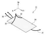
図4、図5は、基本的な吊り型シート11の一例を示す模式図である。吊り型シート11は、乗員100を下側から支持するシート本体24と、当該シート本体24を吊り下げ保持する複数の吊り具30,31,32と、を有している。シート本体24は、少なくとも乗員100の上半身が載置できるものであれば、特に、限定されない。したがって、シート本体24は、特定の形状を維持する硬質材料で構成されてもよいし、乗員100の体型に応じて柔軟に変形可能な柔軟材料(例えば布や樹脂シート、網状部材等)で構成されてもよい。また、乗員100の乗り心地を向上するために、シート本体24の上に、さらに、クッションパッド(図示せず)を載置してもよい。 4 and 5 are schematic diagrams showing an example of a
シート本体24の前部からは、1以上(図4、図5では一つ)の前吊り具31が延びている。各前吊り具31は、このシート本体24の前部を通るとともに、前後方向(図4、図5では前方)かつ上側に延びて、車内の構造物に取り付けられる。シート本体24の後部からは、1以上(図4、図5では一つ)の後吊り具30が延びている。各後吊り具30は、シート本体24の後部を通るとともに、前後方向(図4、図5では後方)かつ上側に延びて車内の構造物に取り付けられる。さらに、シート本体24の両サイドからは2以上(図4、図5では二つ)の横吊り具32が延びている。各横吊り具32は、シート本体24の両サイドを通るとともに、左右方向(図4、図5では左右方向外側)かつ上側に延びて、車内の構造物に取り付けられる。 One or more (one in FIGS. 4 and 5)
ここで、これら吊り具30,31,32は、いずれも、乗員100の荷重に耐えられる程度の強度を有する長尺部材であれば、その構成は、特に限定されない。したがって、吊り具30,31,32は、線状部材でもよいし、幅を有した帯状部材でもよいし、複数の環状体を繋ぎ合わせたチェーン状部材でもよい。また、吊り具30,31,32の素材も、限定されず、例えば、天然繊維、化学繊維、金属、または、これらの組み合わせで構成されてもよい。また、吊り具30,31,32は、全て、同じ構成でもよいし、互いに異なる構成でもよい。例えば、乗員100の体と干渉しやすい横吊り具32は、天然繊維で形成し、後吊り具30および前吊り具31は、金属ワイヤで形成してもよい。 Here, the structures of the
また、これら吊り具30,31,32が取り付けられる車内の構造物は、乗員100の重量に耐えられるのであれば、特に限定されない。したがって、吊り具30,31,32は、例えば、弾性フレーム22またはボディ12に取り付けられてもよい。また、吊り具30,31,32は、車内の構造物に対して、分離不能に固定されてもよいし、着脱可能に取り付けられてもよい。例えば、車内構造物および吊り具30,31,32の末端の一方にフックを、他方に当該フックに着脱自在に引っかけられるループを設けてもよい。 The in-vehicle structure to which these
いずれにしても、シート本体24から延びる吊り具30,31,32が、シート本体24より上側にある車内構造物に取り付けられることで、シート本体24が吊り下げ保持される。そして、車載シートを、こうした吊り型のシートとすることで、車載シートを大幅に軽量化できる。すなわち、従来の車載シートの多くは、座部と座部から立脚する背もたれ部とを有していることが多かった。この場合、背もたれ部の立脚姿勢を維持するために(意図しない倒れを防止するために)、背もたれ部には、通常、金属で構成された硬く重い骨格部材が設けられていた。しかし、骨格部材を設けた場合、車載シートの重量が大きくなり、車両10の燃費または電費の低下を招いていた。 In any case, the
一方、本例では、シート本体24を吊り下げる構成としているため、シート本体24の姿勢は、吊り具30,31,32の張力と、乗員100にかかる力(重力や慣性力)と、が釣り合った位置に自動的に保たれる。その結果、本例では、シート本体24の姿勢を保つための骨格部材が不要となり、シート全体を大幅に軽量化できる。 On the other hand, in this example, since the
また、本例では、シート本体24の前後両側から延びる前吊り具31および後吊り具30に加えて、さらに、シート本体24の左右両側から延びる一対の横吊り具32も設けている。かかる構成とすることで、シート本体24の前後軸周りの揺動、いわゆるロール運動が効果的に抑制できる。すなわち、横吊り具32がなく、前吊り具31および後吊り具30のみでシート本体24を吊り下げ保持した場合、シート本体24は、前後軸周りに容易に揺動する。特に、図1、図2で示すような、前後方向に細長い車両の場合、走行に伴い、こうしたロール運動が生じやすい。シート本体24、ひいては当該シート本体24に載っている乗員100がロール運動すると、乗員100の姿勢が定まらず、各種操作の安定性が低下する。また、乗員100の胸部や頭部が繰り返し動くと、乗り心地が低下し、場合によっては、乗り物酔いを招く。 Further, in this example, in addition to the
本例では、上述した通り、前吊り具31および後吊り具30に加えて二以上の横吊り具32を設けている。この場合、シート本体24のロール運動が、当該横吊り具32により規制されるため、シート本体24のロール運動が効果的に抑制され、乗員100をより安定して支持できる。 In this example, as described above, two or more
なお、図4、図5に示す吊り型シート11の構造は、基本的なものであり、適宜、変更されてもよい。例えば、横吊り具32は、左右方向外側ではなく、図6に示すように、左右方向内側に延びてもよい。また、前吊り具31および後吊り具30も、前後方向外側だけでなく、前後方向内側に延びてもよい。また、図6に示すように、後吊り具30を複数(図6では二つ)設けてもよい。この場合、複数の後吊り具30は、シート本体24の左右方向中心線を対称軸として鏡像配置されてもよい。同様に前吊り具31も複数設けてもよく、この場合、複数の前吊り具31は、シート本体24の左右方向中心線を対称軸として鏡像配置されてもよい。 The structure of the hanging
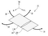
また、シート本体24は、いくつかのパートに分割されてもよい。例えば、図7に示すように、シート本体24は、乗員100の少なくとも背部を下側から支持する第一支持部材26と、乗員100の臀部を下側から支持する第二支持部材28と、に分割されていてもよい。かかる構成とすることで、乗員100の背部を含む上半身の動きと、臀部を含む下半身の動きと、を分けることができ、上半身および下半身それぞれの動きを別個に調整することができる。この場合、第一支持部材26と第二支持部材28は、互いに異なる構成でもよい。例えば、第一支持部材26を柔軟に変形可能な柔軟性材料(例えばシート材や網材等)で構成し、第二支持部材を、第一支持部材26よりも柔軟性に乏しい硬質材料(例えば硬質プラスチック、金属等)で構成してもよい。この場合、第二支持部材28は、第一支持部材26に、部分的にのみ繋がる構成としてもよい。例えば、第二支持部材28の左右方向両端のみが第一支持部材26に繋がっており、第二支持部材28の左右方向中間部分は、第一支持部材26と繋がることなく、フリーな状態としてもよい。かかる構成とすることで、上半身および下半身それぞれの動きを、より明確に分けることができる。 Also, the
この場合、下半身のロール運動より上半身のロール運動の方が抑制されるように、第一、第二支持部材26,28の動きを調整してもよい。かかる構成とすることで、車両走行時に、車両10を通じて路面から入力される振動を、下半身のロール運動で吸収でき、上半身の位置および姿勢をより安定させることができる。こうした構成は、例えば、図7に示すように、第一支持部材26の両サイドから2以上の横吊り具32を延ばす一方で、第二支持部材28から延びる横吊り具32を設けないことで得られる。 In this case, the movements of the first and
また、上半身および下半身ともに、ロール運動を抑制できるように、第一、第二支持部材26,28の動きを調整してもよい。こうした構成は、例えば、図8に示すように、第一支持部材26の両サイドから2以上の横吊り具32を延ばすとともに、第二支持部材28からも2以上の第二横吊り具59を設けることで得られる。 Also, the movements of the first and
次に、吊り型シート11のより具体的な構成例を説明する。図9および図10は、第一の具体例における吊り型シート11の側面図および平面図である。この吊り型シート11は、シート本体24と、吊り具30,31,32として機能する吊りワイヤ33,34,35と、を備えている。吊りワイヤ33,34,35は、いずれも、金属製の素線を単層または多層により合わせて構成される。また、シート本体24は、第一支持部材26と第二支持部材28とに分割されている。 Next, a more specific configuration example of the hanging
第一支持部材26は、複数のワイヤを網状に組み合わせて構成されるネット部材36で構成されており、ネスト部44とラダー部50とに大別される。ネスト部44は、ワイヤをくもの巣状に張り巡らして構成されている。ネスト部44は、略多角形状に貼られた枠ワイヤ46と、当該枠ワイヤ46の中心から枠ワイヤ46まで放射状に延びる複数の放射ワイヤ48と、を備えている。このネスト部44には、乗員100の肩部周辺が載置される。 The
ネスト部44の中心には、基準プレート38が設けられている。図11は、基準プレート38の斜視図である。基準プレート38は、その表面に、三つの係合溝40が周方向に並んで形成された円板状部材である。各係合溝40には、放射ワイヤ48が挿し込まれ、引っかけられる。図11から明らかな通り、各係合溝40は、平面視において径方向外側に向かって開いた逆U字状となっている。そのため、この係合溝40に挿し込まれ、当該係合溝40に沿って進む放射ワイヤ48は、当該基準プレート38内においてUターンすることになる。そして、これにより、基準プレート38からは、六つの放射ワイヤ48(実際にはUターンして繋がっている3本のワイヤ)が放射状に延びる。なお、放射ワイヤ48の係合溝40からの脱落を防止するために、基準プレート38の前面に平板状の蓋体39を取り付けてもよい。 A
この放射ワイヤ48のうち、後方に進む二つの放射ワイヤ48(実際にはUターンして繋がっている一本のワイヤ)が、枠ワイヤ46を越えて後吊りワイヤ33となる。本例では、この二つの後吊りワイヤ33の間に、複数のクロスワイヤ45をかけ渡し、乗員100の頭部が載置されるヘッドレスト部51を構成している。また、放射ワイヤ48のうち、左右方向に進む二つの放射ワイヤ48が枠ワイヤ46を越えて横吊りワイヤ35となる。つまり、後吊りワイヤ33および横吊りワイヤ35の始点は、いずれも、基準プレート38となる。また、基準プレート38の係合溝40は、後吊りワイヤ33および横吊りワイヤ35の始点が係合される係合部として機能する。このように係合部(係合溝40)を有する基準プレート38を設けることで、後吊りワイヤ33および横吊りワイヤ35の位置決めが容易となる。 Of the radiating
また、後吊りワイヤ33および横吊りワイヤ35の始点が、同じ一つの基準プレート38にあるため、第一支持部材26が、当該基準プレート38を基準として安定して吊り下がる。結果として、乗員100の乗り心地を向上できる。さらに、かかる構成とすることで、乗員100の胸部付近のロール運動を小さくできる。すなわち、シート本体24のロール運動は、横吊りワイヤ35によって規制されるため、横吊りワイヤ35に近い箇所ほどロール運動が抑制される。一方、本例において、基準プレート38は、乗員100の肩甲骨または胸部の近くに位置する。かかる基準プレート38を起点として横吊りワイヤ35を延ばすことで、乗員100の胸部周辺のロール運動が効果的に抑制され、乗員100の乗り心地をより向上できる。 In addition, since the starting points of the
ネスト部44の前端には、ラダー部50が接続されている。ラダー部50は、前後方向に延びる一対のサイドワイヤ54と、一対のサイドワイヤ54の間に掛け渡される複数のクロスワイヤ56と、を備えている。このラダー部50には、乗員100の胸部から腰部付近が載置される。なお、クロスワイヤ56の配置間隔を保つために、所定の長さを有したカラー62を用いてもよい。すなわち、図12に示すように、クロスワイヤ56とサイドワイヤ54の接合点と、カラー62と、が交互に並ぶように、サイドワイヤ54にカラー62を挿通してもよい。かかる構成とすることで、クロスワイヤ56の配置間隔がカラー62の長さに規定される。 A
以上の説明から明らかな通り、乗員100の背部を支持する第一支持部材26は、複数のワイヤを組み合わせてなるネット状部材で構成されている。かかる構成とすることで、乗員100の体格に応じて第一支持部材26の形状が柔軟に変形する。そして、これにより、様々な体格の乗員100を安定して支持できる。 As is clear from the above description, the
ラダー部50の前端には、第二支持部材28が接続されている。第二支持部材28は、乗員100の臀部が載置される支持パン42と、当該支持パン42を下側から支える三角ワイヤ52と、を備えている。支持パン42は、臀部がはまり込むように、下方にくぼんだ凹部を有した成型品であり、例えば樹脂等で構成される。この支持パン42は、その下側に配置される三角ワイヤ52で拘束され、支持されている。三角ワイヤ52は、三つのワイヤを、略三角形を成すように互いに接続して構成される。また、この三角ワイヤ52の二つの頂点は、ラダー部50の前端における左右両端に接続されている。ここで、ラダー部50および三角ワイヤ52は、いずれも、ある程度の柔軟性を有するワイヤで構成されているため、比較的自由に変形できる。その結果、第二支持部材28は、第一支持部材26に対して比較的容易に動くことができる。 A
以上のようなシート本体24は、後吊りワイヤ33、前吊りワイヤ34、および横吊りワイヤ35で吊り下げ保持されている。後吊りワイヤ33は、上述した通り、基準プレート38から上側かつ後方に延びて、シート本体24の前部を通過して、弾性フレーム22のポイントP1,P2に固定される。ポイントP1,P2は、図1、図2に示す通り、弾性フレーム22の後側二又部22rに存在する。 The
また、横吊りワイヤ35は、基準プレート38から上側かつ左右方向外側に延びて、シート本体24の両サイドを通過して、弾性フレーム22のポイントP3,P4に固定される。ポイントP3,P4は、ボディ12に存在する。さらに、前吊りワイヤ34は、三角ワイヤ52の前端の頂点(すなわちシート本体24の前部)から上側かつ前方に延びて、弾性フレーム22のポイントP5に固定される。ポイントP5は、弾性フレーム22の前側二又部22fよりやや後方に位置している。 The
以上の通り、本例では、シート本体24を、第一支持部材26と、第二支持部材28と、に分割し、当該シート本体24を、吊りワイヤ33,34,35で吊り下げ保持している。かかる構成とすることで、図7に示す例と同様に、硬く重いフレームが不要となり、シート本体24の大幅な軽量化が可能となる。また、本例では、後吊りワイヤ33および前吊りワイヤ34に加えて、横吊りワイヤ35も設けているため、シート本体24のロール運動を効果的に抑制できる。結果として、乗員100の姿勢が安定し、車酔いしにくくなり、快適な乗り心地が得られる。特に、本例では、横吊りワイヤ35を第一支持部材26にのみ取り付け、第二支持部材28には取り付けていない。かかる構成とすることで、第二支持部材28が第一支持部材26よりもロール運動しやすくなり、乗員100の下半身が、上半身に比べて、ロール運動しやすくなる。その結果、路面からの振動入力が、もっぱら下半身のロール運動で吸収され、上半身の動きがより効果的に抑制される。そして、これにより、乗員100の胸部や頭部の姿勢がより安定し、乗り心地がより向上する。 As described above, in this example, the
また、第一支持部材26自体は、上述した通り、横吊りワイヤ35によりロール運動が抑制されているため、乗員100の寝返りが打ちやすくなる。その結果、例えば、この吊り型シート11を自動運転車両に搭載した場合、乗員100は、比較的容易に寝返りを打つことができるため、長時間乗車してもエコノミー症候群の発症を効果的に防止できる。 In addition, as described above, the roll motion of the
また、本例では、後吊りワイヤ33および前吊りワイヤ34を、適度な弾性を有する弾性フレーム22に取り付けている。かかる構成とすることで、路面からの振動入力の一部が、吊りワイヤ33,34に伝達されることなく、弾性フレーム22の弾性変位で吸収される。その結果、乗員100の乗り心地をより向上できる。 Further, in this example, the
また、これまでの説明で明らかな通り、本例では、略弧状の弾性フレーム22の下側にシート本体24を吊り下げるとともに、シート本体24と弾性フレーム22の後端との間にバッテリ20を配置している。かかる構成とすることで、後突時の衝撃を、弾性フレーム22およびバッテリ20で吸収でき、乗員100を保護することができる。すなわち、車両10後突時に、弾性フレーム22の後部に、前向きの衝突荷重が入力されると、弾性フレーム22の後部が弾性変形しながら前方に移動する。この弾性変形により衝突荷重の一部が吸収される。また、弾性フレーム22の後部の前方移動に伴い、当該弾性フレーム22に取り付けられた後車軸18rがバッテリ20に衝突する。バッテリ20は、通常、硬く頑丈であるため、衝突荷重を受け止めることができる。そして、これによりシート本体24に乗っている乗員100への衝突荷重の入力を低減でき、乗員100を適切に保護できる。 As is clear from the above description, in this example, the
次に、他の吊り型シート11の具体例について、図13から図15を参照して説明する。図13および図14は、第二の具体例における吊り型シート11の側面図および平面図である。また、図15は、この具体例における第二支持部材28の斜視図である。この吊り型シート11は、第一の具体例と比べて第二支持部材28の吊り下げ方が異なっている。具体的には、第二の具体例において、前吊りワイヤ34は、第二支持部材28の前端から、上側前方ではなく、上側後方に延びて、弾性フレーム22のポイントP6に固定されている。また、第二支持部材28には、さらに、二つの第二横吊りワイヤ60も取り付けられている。第二横吊りワイヤ60は、第二支持部材28の前端における左右両端から上側かつ左右方向内側に延びている。この第二横吊りワイヤ60は、前吊りワイヤ34と同じポイント、すなわち弾性フレーム22のポイントP6に固定されている。 Next, another specific example of the hanging
このように、第一支持部材26だけでなく、第二支持部材28にも横吊りワイヤ60を取り付けることで、第二支持部材28、ひいては、乗員100の下半身もロール運動しにくくなる。ここで、第一の具体例では、乗員100の下半身を積極的にロール運動させることで、上半身のロール運動を抑制させている。しかしながら、下半身のロール運動をどの程度抑制すればよいかは、吊り型シート11が搭載される車両10の構成や、当該車両が走行する路面の状況、走行目的等によって異なる。したがって、下半身のロール運動をある程度抑制したい場合には、この第二の具体例が適していると言える。 By attaching the
また、本例では、二つの第二横吊りワイヤ60は、シート本体24の外側方向ではなく、内側方向に延びている。かかる構成とすることで、乗員100のシート本体24からの横滑りが防止され、意に反した乗員100のシート本体からの脱落が効果的に防止できる。 Also, in this example, the two second
ところで、こうした前吊りワイヤ34および第二横吊りワイヤ60は、互いに独立していてもよいし、互いに繋がっていてもよい。例えば、図15に示すように、支持パン42に三つの挿通孔58を形成するとともに、三角ワイヤ52の一部を当該挿通孔58から上側に引き上げて、前吊りワイヤ34および第二横吊りワイヤ60として用いてもよい。 By the way, the
次に、他の吊り型シート11の具体例について、図16、図17を参照して説明する。図16および図17は、第三の具体例における吊り型シート11の側面図および平面図である。この吊り型シート11は、第一の具体例と比べて、第二支持部材28に第二横吊りワイヤ60が取り付けられている点で相違する。第三の具体例において、第二横吊りワイヤ60は、第二支持部材28の前端における左右両端から上側かつ左右方向外側に延びて、ボディ12に存在するポイントP7,P8に接続される。 Next, another specific example of the hanging
つまり、第三の具体例においても、第二の具体例と同様に、第一支持部材26だけでなく、第二支持部材28にも横吊りワイヤ60を取り付けているため、乗員の上半身に加えて下半身もロール運動しにくくなる。また、第二横吊りワイヤ60が、左右方向外側に延びているため、第二の具体例と比べて、当該第二横吊りワイヤ60が、シート本体24への乗員100の乗り降りの邪魔になりにくい。 That is, in the third specific example, as in the second specific example, the
次に、他の吊り型シート11の具体例について、図18を参照して説明する。図18は、第四の具体例における吊り型シート11の平面図である。第四の具体例において第一支持部材26は、ネスト部44およびラダー部50に加えて、さらに、一対のサイド部64を有している。サイド部64は、ネスト部44およびラダー部50の両サイドに接続されており、乗員100の肩や上腕を支持する。サイド部64からは、2対、四つの横吊りワイヤ35が、上側かつ左右方向内側に延びて、弾性フレーム22のポイントP10,P11に取り付けられる。また、ネスト部44の後端からは、一つの後吊りワイヤ33が上側かつ後方に延びて、弾性フレーム22のポイントP9に取り付けられる。さらに、第二支持部材28の前端からは、一つの前吊りワイヤ34が上側かつ前方に延びて、弾性フレーム22のポイントP5に接続されている。 Next, another specific example of the hanging
つまり、本例によれば、吊りワイヤ33,34,35は、全て、弾性を有した弾性フレーム22に接続されている。かかる構成とすることで、路面から入力される振動が、シート本体24により伝達されづらくなりなり、乗り心地がより向上する。 In other words, according to this example, the
また、車両10では、後輪16のタイヤの縦バネ係数と、乗員100を含む車両10全体のロール慣性と、に依存して生じる車両10全体のロール共振によるタイヤの歪みが生じる。本例では、後輪の車軸に連結された弾性フレーム22に、シート本体24を吊り下げることで、当該シート本体24に乗る乗員100を、車体ロール共振を抑えるダイナミックダンパとして活用できる。そして、これにより後輪タイヤの歪みを最小限に抑えることができ、転がり抵抗を低減できる。 Further, in the
なお、これまで説明した構成は、いずれも、一例であり、少なくとも、シート本体24を、1以上の後吊り具30、1以上の前吊り具31、および、2以上の横吊り具32を介して車内の構造物から吊り下げ保持されるのであれば、その他の構成は、適宜、変更されてもよい。したがって、シート本体24の構成や形状は、適宜、変更されてもよい。また、吊り具の構成や個数、位置等も適宜、変更されてもよい。 It should be noted that the configurations described so far are all examples, and at least the
また、これまでの説明では、一人乗り用の三輪車両に搭載される吊り型シート11を例に挙げて説明したが、吊り型シート11が搭載される車両の種類や形態は、適宜、変更されてもよい。例えば、図19に示すように、二人乗り用の四輪車両に吊り型シート11を二つ、搭載してもよい。この場合、弾性フレーム22は、車両10の車幅方向に間隔を開けて、二つ、設けられてもよい。また、吊り型シート11は、弾性フレーム22の存在しない車両に搭載されるのでもよい。また、弾性フレーム22の両端は、車軸18f,18rに変えて、または、加えて、他の車体部材、例えば、車両ボディや骨格部材などに連結されていてもよい。 Further, in the above description, the
10 車両、11 吊り型シート、12 ボディ、14 前輪、16 後輪、18f 前車軸、18r 後車軸、20 バッテリ、22 弾性フレーム、22f 前側二又部、22r 後側二又部、24 シート本体、26 第一支持部材、28 第二支持部材、30 後吊り具、31 前吊り具、32 横吊り具、33 後吊りワイヤ、34 前吊りワイヤ、35 横吊りワイヤ、36 ネット部材、38 基準プレート、39 蓋体、40 係合溝、42 支持パン、44 ネスト部、45,56 クロスワイヤ、46 枠ワイヤ、48 放射ワイヤ、50 ラダー部、51 ヘッドレスト部、52 三角ワイヤ、54 サイドワイヤ、58 挿通孔、59 第二横吊り具、60 第二横吊りワイヤ、62 カラー、64 サイド部、100 乗員。
10 vehicle, 11 suspended seat, 12 body, 14 front wheel, 16 rear wheel, 18f front axle, 18r rear axle, 20 battery, 22 elastic frame, 22f front fork, 22r rear fork, 24 seat body, 26 first support member, 28 second support member, 30 rear suspension tool, 31 front suspension tool, 32 side suspension tool, 33 rear suspension wire, 34 front suspension wire, 35 lateral suspension wire, 36 net member, 38 reference plate, 39 lid, 40 engagement groove, 42 support pan, 44 nest portion, 45, 56 cross wire, 46 frame wire, 48 radiation wire, 50 ladder portion, 51 headrest portion, 52 triangular wire, 54 side wire, 58 insertion hole , 59 second lateral sling, 60 second lateral sling wire, 62 collar, 64 side part, 100 occupant.
Claims (7)
Translated fromJapanese乗員を下側から支持するシート本体と、
前記シート本体の前部を通るとともに、前後方向かつ上側に延びて、車内の構造物に取り付けられる1以上の前吊り具と、
前記シート本体の後部を通るとともに、前後方向かつ上側に延びて、車内の構造物に取り付けられる1以上の後吊り具と、
前記シート本体の両サイドを通るとともに、左右方向かつ上側に延びて、車内の構造物に取り付けられる2以上の横吊り具と、
を備え、前記シート本体が、前記1以上の前吊り具と、前記1以上の後吊り具と、前記2以上の横吊り具と、で吊り下げ保持されており、
前記1以上の前吊り具と、前記1以上の後ろ吊り具と、前記2以上の横吊り具と、はいずれも、前記車両の内部に位置し、
前記2以上の横吊り具は、前記シート本体の両サイドそれぞれから左右方向外側または左右方向内側に延びて、車内の構造物に取り付けられ、
前記1以上の前吊り具および前記1以上の後ろ吊り具は、車両前後方向に延びる弾性フレームに取り付けられており、
前記弾性フレームは、車両前部に位置する前車軸および車両後部に位置する後車軸に接続されている、
ことを特徴とする吊り型シート。A hanging seat mounted on a vehicle,
a seat body that supports an occupant from below;
one or more front slings that pass through the front part of the seat body, extend in the front-rear direction and upward, and are attached to a structure in the vehicle;
one or more rear slings that pass through the rear part of the seat body, extend in the front-rear direction and upward, and are attached to a structure in the vehicle;
two or more horizontal slings that pass through both sides of the seat body, extend in the left-right direction and upward, and are attached to structures in the vehicle;
wherein the seat body is suspended and held by the one or more front slings, the one or more rear slings, and the two or more side slings;
The one or more front slings, the one or more rear slings, and the two or more side slings are all positioned inside the vehicle,
The two or more horizontal slings extend laterally outward or laterally inward from each side of the seat body and are attached to a structure inside the vehicle,
The one or more front suspension devices and the one or more rear suspension devices are attached to an elastic frame extending in the longitudinal direction of the vehicle,
The elastic frame is connected to a front axle located at the front of the vehicle and a rear axle located at the rear of the vehicle.
A hanging sheet characterized by:
前記シート本体は、少なくとも、
前記乗員の少なくとも背部が載置される第一支持部材と、
前記乗員の少なくとも臀部が載置される第二支持部材と、
に分割されている、ことを特徴とする吊り型シート。The hanging sheet according to claim 1,
The seat body has at least
a first support member on which at least the back of the occupant is placed;
a second support member on which at least the buttocks of the occupant are placed;
A hanging sheet, characterized in that it is divided into
前記第一支持部材は、複数のワイヤを網状に組み合わせて構成され、前記乗員の少なくとも背部が載置されるネット部材を含む、ことを特徴とする吊り型シート。The hanging sheet according to claim 2,
The suspension-type seat, wherein the first support member includes a net member configured by combining a plurality of wires in a mesh shape, and including a net member on which at least the back of the occupant is placed.
乗員を下側から支持するシート本体と、
前記シート本体の前部を通るとともに、前後方向かつ上側に延びて、車内の構造物に取り付けられる1以上の前吊り具と、
前記シート本体の後部を通るとともに、前後方向かつ上側に延びて、車内の構造物に取り付けられる1以上の後吊り具と、
前記シート本体の両サイドを通るとともに、左右方向かつ上側に延びて、車内の構造物に取り付けられる2以上の横吊り具と、
を備え、前記シート本体が、前記1以上の前吊り具と、前記1以上の後吊り具と、前記2以上の横吊り具と、で吊り下げ保持されており、
前記1以上の前吊り具と、前記1以上の後ろ吊り具と、前記2以上の横吊り具と、はいずれも、前記車両の内部に位置し、
前記シート本体は、少なくとも、
前記乗員の少なくとも背部が載置される第一支持部材と、
前記乗員の少なくとも臀部が載置される第二支持部材と、
に分割されており、
前記第一支持部材は、複数のワイヤを網状に組み合わせて構成され、前記乗員の少なくとも背部が載置されるネット部材を含み、
前記第一支持部材の両サイドから前記横吊り具が延びる一方で、前記第二支持部材から延びる前記横吊り具がない、ことを特徴とする吊り型シート。A hanging seat mounted on a vehicle,
a seat body that supports an occupant from below;
one or more front slings that pass through the front part of the seat body, extend in the front-rear direction and upward, and are attached to a structure in the vehicle;
one or more rear slings that pass through the rear part of the seat body, extend in the front-rear direction and upward, and are attached to a structure in the vehicle;
two or more horizontal slings that pass through both sides of the seat body, extend in the left-right direction and upward, and are attached to structures in the vehicle;
wherein the seat body is suspended and held by the one or more front slings, the one or more rear slings, and the two or more side slings;
The one or more front slings, the one or more rear slings, and the two or more side slings are all positioned inside the vehicle,
The seat body has at least
a first support member on which at least the back of the occupant is placed;
a second support member on which at least the buttocks of the occupant are placed;
is divided into
The first support member includes a net member configured by combining a plurality of wires in a net shape and on which at least the back of the occupant is placed,
A suspension-type sheet, wherein the horizontal hangers extend from both sides of the first support member, while the horizontal hangers do not extend from the second support member.
乗員を下側から支持するシート本体と、
前記シート本体の前部を通るとともに、前後方向かつ上側に延びて、車内の構造物に取り付けられる1以上の前吊り具と、
前記シート本体の後部を通るとともに、前後方向かつ上側に延びて、車内の構造物に取り付けられる1以上の後吊り具と、
前記シート本体の両サイドを通るとともに、左右方向かつ上側に延びて、車内の構造物に取り付けられる2以上の横吊り具と、
を備え、前記シート本体が、前記1以上の前吊り具と、前記1以上の後吊り具と、前記2以上の横吊り具と、で吊り下げ保持されており、
前記シート本体は、少なくとも、
前記乗員の少なくとも背部が載置される第一支持部材と、
前記乗員の少なくとも臀部が載置される第二支持部材と、
に分割されており、
前記第一支持部材は、複数のワイヤを網状に組み合わせて構成され、前記乗員の少なくとも背部が載置されるネット部材を含み、
前記第一支持部材の両サイドおよび前記第二支持部材の両サイドそれぞれから前記横吊り具が延びている、ことを特徴とする吊り型シート。A hanging seat mounted on a vehicle,
a seat body that supports an occupant from below;
one or more front slings that pass through the front part of the seat body, extend in the front-rear direction and upward, and are attached to a structure in the vehicle;
one or more rear slings that pass through the rear part of the seat body, extend in the front-rear direction and upward, and are attached to a structure in the vehicle;
two or more horizontal slings that pass through both sides of the seat body, extend in the left-right direction and upward, and are attached to structures in the vehicle;
wherein the seat body is suspended and held by the one or more front slings, the one or more rear slings, and the two or more side slings;
The seat body has at least
a first support member on which at least the back of the occupant is placed;
a second support member on which at least the buttocks of the occupant are placed;
is divided into
The first support member includes a net member configured by combining a plurality of wires in a net shape and on which at least the back of the occupant is placed,
The suspension type seat, wherein the horizontal suspension members extend from both sides of the first support member and both sides of the second support member.
乗員を下側から支持するシート本体と、
前記シート本体の前部を通るとともに、前後方向かつ上側に延びて、車内の構造物に取り付けられる1以上の前吊り具と、
前記シート本体の後部を通るとともに、前後方向かつ上側に延びて、車内の構造物に取り付けられる1以上の後吊り具と、
前記シート本体の両サイドを通るとともに、左右方向かつ上側に延びて、車内の構造物に取り付けられる2以上の横吊り具と、
を備え、前記シート本体が、前記1以上の前吊り具と、前記1以上の後吊り具と、前記2以上の横吊り具と、で吊り下げ保持されており、
さらに、前記シート本体に取り付けられ、吊り具の始点が係合可能な係合部を有する基準プレートを備え、
前記1以上の後吊り具のうち少なくとも一つ、および、前記2以上の横吊り具のうち少なくとも二つ、それぞれの始点が、前記基準プレートの前記係合部に係合されている、
ことを特徴とする吊り型シート。A hanging seat mounted on a vehicle,
a seat body that supports an occupant from below;
one or more front slings that pass through the front part of the seat body, extend in the front-rear direction and upward, and are attached to a structure in the vehicle;
one or more rear slings that pass through the rear part of the seat body, extend in the front-rear direction and upward, and are attached to a structure in the vehicle;
two or more horizontal slings that pass through both sides of the seat body, extend in the left-right direction and upward, and are attached to structures in the vehicle;
wherein the seat body is suspended and held by the one or more front slings, the one or more rear slings, and the two or more side slings;
Furthermore, a reference plate is attached to the seat body and has an engaging portion with which the starting point of the sling can be engaged,
At least one of the one or more rear slings and at least two of the two or more side slings, each starting point of which is engaged with the engaging portion of the reference plate,
A hanging sheet characterized by:
乗員を下側から支持するシート本体と、
前記シート本体の前部を通るとともに、前後方向かつ上側に延びて、車内の構造物に取り付けられる1以上の前吊り具と、
前記シート本体の後部を通るとともに、前後方向かつ上側に延びて、車内の構造物に取り付けられる1以上の後吊り具と、
前記シート本体の両サイドを通るとともに、左右方向かつ上側に延びて、車内の構造物に取り付けられる2以上の横吊り具と、
を備え、前記シート本体が、前記1以上の前吊り具と、前記1以上の後吊り具と、前記2以上の横吊り具と、で吊り下げ保持されており、
前記1以上の前吊り具と、前記1以上の後ろ吊り具と、前記2以上の横吊り具と、はいずれも、前記車両の内部に位置し、
前記シート本体は、少なくとも、
前記乗員の少なくとも背部が載置される第一支持部材と、
前記乗員の少なくとも臀部が載置される第二支持部材と、
に分割されており、
前記第二支持部材は、前記第一支持部材に、部分的にのみ直接繋がっている、
ことを特徴とする吊り型シート。A hanging seat mounted on a vehicle,
a seat body that supports an occupant from below;
one or more front slings that pass through the front part of the seat body, extend in the front-rear direction and upward, and are attached to a structure in the vehicle;
one or more rear slings that pass through the rear part of the seat body, extend in the front-rear direction and upward, and are attached to a structure in the vehicle;
two or more horizontal slings that pass through both sides of the seat body, extend in the left-right direction and upward, and are attached to structures in the vehicle;
wherein the seat body is suspended and held by the one or more front slings, the one or more rear slings, and the two or more side slings;
The one or more front slings, the one or more rear slings, and the two or more side slings are all positioned inside the vehicle,
The seat body has at least
a first support member on which at least the back of the occupant is placed;
a second support member on which at least the buttocks of the occupant are placed;
is divided into
the second support member is only partially directly connected to the first support member;
A hanging sheet characterized by:
Priority Applications (3)
| Application Number | Priority Date | Filing Date | Title |
|---|---|---|---|
| JP2019111464AJP7255381B2 (en) | 2019-06-14 | 2019-06-14 | hanging seat |
| US16/898,898US11491900B2 (en) | 2019-06-14 | 2020-06-11 | Hanging type seat |
| CN202010529443.5ACN112078456B (en) | 2019-06-14 | 2020-06-11 | Suspension seat |
Applications Claiming Priority (1)
| Application Number | Priority Date | Filing Date | Title |
|---|---|---|---|
| JP2019111464AJP7255381B2 (en) | 2019-06-14 | 2019-06-14 | hanging seat |
Publications (2)
| Publication Number | Publication Date |
|---|---|
| JP2020203544A JP2020203544A (en) | 2020-12-24 |
| JP7255381B2true JP7255381B2 (en) | 2023-04-11 |
Family
ID=73736139
Family Applications (1)
| Application Number | Title | Priority Date | Filing Date |
|---|---|---|---|
| JP2019111464AActiveJP7255381B2 (en) | 2019-06-14 | 2019-06-14 | hanging seat |
Country Status (3)
| Country | Link |
|---|---|
| US (1) | US11491900B2 (en) |
| JP (1) | JP7255381B2 (en) |
| CN (1) | CN112078456B (en) |
Families Citing this family (1)
| Publication number | Priority date | Publication date | Assignee | Title |
|---|---|---|---|---|
| JP7255381B2 (en)* | 2019-06-14 | 2023-04-11 | トヨタ自動車株式会社 | hanging seat |
Citations (9)
| Publication number | Priority date | Publication date | Assignee | Title |
|---|---|---|---|---|
| JP2000333732A (en) | 1999-05-25 | 2000-12-05 | Hisatsugu Kameoka | Hammock-like automobile accessory for creating new sleeping and storage space when staying overnight in automobile or the like |
| JP2006081685A (en) | 2004-09-15 | 2006-03-30 | Saito Nenshi:Kk | Hammock |
| US20150173496A1 (en) | 2013-12-17 | 2015-06-25 | Hanson Eugene Ely | Exterior-Anchored Automobile Hammock |
| JP2016016754A (en) | 2014-07-08 | 2016-02-01 | トヨタ自動車株式会社 | Vehicular seat |
| JP2017196436A (en) | 2013-06-14 | 2017-11-02 | 川口 潔 | hammock |
| JP2018020596A (en) | 2016-08-01 | 2018-02-08 | トヨタ自動車株式会社 | Vehicle seat |
| DE202018102328U1 (en) | 2018-04-25 | 2018-05-02 | La Siesta Gmbh | Hanging chair with spreader stick |
| US20190001844A1 (en) | 2017-06-30 | 2019-01-03 | Toyota Motor Engineering & Manufacturing North America, Inc. | Sway control for suspended furniture in a vehicle |
| DE102018104449A1 (en) | 2018-02-27 | 2019-08-29 | Jana Grewe | Mobile seat device for a means of transportation and means of transportation |
Family Cites Families (49)
| Publication number | Priority date | Publication date | Assignee | Title |
|---|---|---|---|---|
| US1138820A (en)* | 1914-05-01 | 1915-05-11 | Frank B Wersel Jr | Hammock-cot. |
| US1369638A (en)* | 1920-07-20 | 1921-02-22 | Harriet A Edmonds | Bath-hammock |
| US2163198A (en)* | 1937-04-12 | 1939-06-20 | Sarah L Gossard | Body support for railroad coach cars |
| US2260584A (en)* | 1939-08-22 | 1941-10-28 | Frank M Hoover Inc | Baby hammock |
| US2348217A (en)* | 1941-07-18 | 1944-05-09 | Jones Byron Quinby | Hammock |
| US2601488A (en)* | 1947-10-03 | 1952-06-24 | Paul E Allen | Auto bed |
| US2829702A (en)* | 1955-10-27 | 1958-04-08 | Charles E Keating | High strength safety seat |
| US3314720A (en)* | 1965-02-11 | 1967-04-18 | Millington Ralph | Safety troop seat |
| US3454968A (en)* | 1967-10-09 | 1969-07-15 | Robert P Beckman | Auto baby hammock |
| US3524673A (en)* | 1968-04-08 | 1970-08-18 | Western Sales & Supply Co | Bed for truck cabs |
| US4258951A (en)* | 1977-03-09 | 1981-03-31 | Lock Industrial Developments | Collapsible chairs and wheelchairs |
| US4474347A (en)* | 1977-12-09 | 1984-10-02 | Ara, Inc. | Crashworthy seat |
| US4221424A (en)* | 1979-02-09 | 1980-09-09 | Martin A. Eiserman | Motor vehicle sleeper |
| US4602816A (en)* | 1984-09-04 | 1986-07-29 | General Motors Corporation | Motor vehicle sling seat |
| US5170521A (en)* | 1992-06-15 | 1992-12-15 | Light Robert W | Portable sleeper for a land vehicle |
| US5342111A (en)* | 1992-12-21 | 1994-08-30 | General Motors Corporation | Retractable seat |
| US6199252B1 (en)* | 1995-11-27 | 2001-03-13 | Lear Corporation | Modular seat assembly and method of installing the same within a vehicle |
| US5806910A (en)* | 1996-04-30 | 1998-09-15 | Chrysler Corporation | Vehicle adjustable sling seat |
| US5944381A (en)* | 1998-09-14 | 1999-08-31 | Nguyen; Xuan C. | Hanging chair |
| US6550858B1 (en)* | 2000-09-21 | 2003-04-22 | Lear Corporation | Extricable seat assembly |
| DE10341483B3 (en)* | 2003-09-05 | 2005-03-17 | Autoflug Gmbh | Suspended safety seat for land, air or sea vehicle has textile holding belts in belt rolling units which can be set by user to run freely or be locked |
| DE102004044235A1 (en)* | 2004-09-14 | 2006-03-30 | Recaro Aircraft Seating Gmbh & Co. Kg | Passenger seat, in particular passenger seat |
| WO2007031216A1 (en)* | 2005-09-15 | 2007-03-22 | Autoflug Gmbh | Textile seat that is suspended in a textile supporting frame |
| KR20080059251A (en)* | 2005-10-25 | 2008-06-26 | 인티어 오토모티브, 인크. | Active Head Suppression |
| US7234177B1 (en)* | 2006-06-14 | 2007-06-26 | Drevitson Kyle C | Auto hammock rocker |
| DE102007002372B3 (en)* | 2007-01-16 | 2007-12-20 | Autoflug Gmbh | Safety seat for use in e.g. land vehicle, has tension belts provided within seat part and running from front fastener provided at seat part to connection with holding belt along side edges of seat part |
| DE102007002371B3 (en)* | 2007-01-16 | 2008-05-21 | Autoflug Gmbh | Safety seat for e.g. land vehicle, has belt sections with shoulder belts guided up to fastener arranged at front edge of seat part, where shoulder belts are connected with one another by transverse joints |
| US7530635B2 (en)* | 2007-05-21 | 2009-05-12 | Schramek-Flye Kadie M | Child safety seat |
| US20090070930A1 (en)* | 2007-09-17 | 2009-03-19 | Irma Luz Roman | Sleepy shopper hammock sling |
| US8117691B2 (en)* | 2008-02-18 | 2012-02-21 | Bishop Louis L | Adjustable suspension sleep device and method of use |
| US7905545B2 (en)* | 2008-09-12 | 2011-03-15 | Lear Corporation | Vehicle seat assembly having a mounting member to mount an electric component |
| DE102008064663B4 (en)* | 2008-10-06 | 2013-08-22 | Fico Cables Lda | support mat |
| DE102008051603A1 (en)* | 2008-10-14 | 2010-04-15 | Lufthansa Technik Ag | Seat for a transport |
| EP2371620A1 (en)* | 2010-04-01 | 2011-10-05 | BAE Systems Safety Products Inc. | Sling seat |
| CN103906654B (en)* | 2011-08-31 | 2016-05-11 | 提爱思科技股份有限公司 | Seat unit |
| US9072368B2 (en)* | 2013-05-24 | 2015-07-07 | John H. Mueller | Supporting a hammock on a vehicle |
| WO2015011803A1 (en)* | 2013-07-24 | 2015-01-29 | トヨタ自動車株式会社 | Seat |
| JP6070601B2 (en)* | 2014-02-26 | 2017-02-01 | トヨタ自動車株式会社 | Vehicle seat |
| JP6098576B2 (en)* | 2014-06-20 | 2017-03-22 | トヨタ自動車株式会社 | Vehicle seat |
| US10897982B2 (en)* | 2015-10-02 | 2021-01-26 | Dutch Clips LLC | Hammock |
| US20170127807A1 (en)* | 2015-11-06 | 2017-05-11 | Brent D Lindberg | Day-Cab Lounger |
| US9809140B2 (en)* | 2016-02-02 | 2017-11-07 | Notel Enterprise LLC | Platform system for vehicle interior |
| US10232762B2 (en)* | 2016-05-04 | 2019-03-19 | Nicholas Gordon Eddy | Convertible cargo hitch and hammock assembly |
| JP6512196B2 (en)* | 2016-09-15 | 2019-05-15 | トヨタ自動車株式会社 | Vehicle seat |
| JP6958211B2 (en)* | 2017-10-12 | 2021-11-02 | トヨタ自動車株式会社 | Vehicle seat |
| US10493878B2 (en)* | 2017-12-22 | 2019-12-03 | Faurecia Automotive Seating, Llc | Motion sickness mitigation |
| US10377275B2 (en)* | 2017-12-28 | 2019-08-13 | Faurecia Automotive Seating, Llc | Motion sickness mitigation |
| US10710487B2 (en)* | 2018-02-27 | 2020-07-14 | Ford Global Technologies, Llc | Seating cargo retention and lounging system |
| JP7255381B2 (en)* | 2019-06-14 | 2023-04-11 | トヨタ自動車株式会社 | hanging seat |
- 2019
- 2019-06-14JPJP2019111464Apatent/JP7255381B2/enactiveActive
- 2020
- 2020-06-11CNCN202010529443.5Apatent/CN112078456B/enactiveActive
- 2020-06-11USUS16/898,898patent/US11491900B2/enactiveActive
Patent Citations (9)
| Publication number | Priority date | Publication date | Assignee | Title |
|---|---|---|---|---|
| JP2000333732A (en) | 1999-05-25 | 2000-12-05 | Hisatsugu Kameoka | Hammock-like automobile accessory for creating new sleeping and storage space when staying overnight in automobile or the like |
| JP2006081685A (en) | 2004-09-15 | 2006-03-30 | Saito Nenshi:Kk | Hammock |
| JP2017196436A (en) | 2013-06-14 | 2017-11-02 | 川口 潔 | hammock |
| US20150173496A1 (en) | 2013-12-17 | 2015-06-25 | Hanson Eugene Ely | Exterior-Anchored Automobile Hammock |
| JP2016016754A (en) | 2014-07-08 | 2016-02-01 | トヨタ自動車株式会社 | Vehicular seat |
| JP2018020596A (en) | 2016-08-01 | 2018-02-08 | トヨタ自動車株式会社 | Vehicle seat |
| US20190001844A1 (en) | 2017-06-30 | 2019-01-03 | Toyota Motor Engineering & Manufacturing North America, Inc. | Sway control for suspended furniture in a vehicle |
| DE102018104449A1 (en) | 2018-02-27 | 2019-08-29 | Jana Grewe | Mobile seat device for a means of transportation and means of transportation |
| DE202018102328U1 (en) | 2018-04-25 | 2018-05-02 | La Siesta Gmbh | Hanging chair with spreader stick |
Also Published As
| Publication number | Publication date |
|---|---|
| US20200391635A1 (en) | 2020-12-17 |
| JP2020203544A (en) | 2020-12-24 |
| CN112078456A (en) | 2020-12-15 |
| US11491900B2 (en) | 2022-11-08 |
| CN112078456B (en) | 2023-09-08 |
Similar Documents
| Publication | Publication Date | Title |
|---|---|---|
| US9475413B2 (en) | Vehicle | |
| CN102910098B (en) | Seat | |
| CN110182110A (en) | Seat for vehicle | |
| JP6315788B2 (en) | Vehicle seat belt mounting structure | |
| JP2016094071A (en) | Vehicle seat | |
| JP7255381B2 (en) | hanging seat | |
| JP6074500B2 (en) | Vehicle seat | |
| US8955909B2 (en) | Vehicle | |
| CN103097186B (en) | Auto use chair | |
| US8876162B2 (en) | Vehicle | |
| JP6543923B2 (en) | Vehicle seat with functional skin | |
| KR20230099063A (en) | Car seat for pet | |
| JP5785858B2 (en) | Headrest and vehicle seat | |
| JP2013523531A (en) | Car with variable backrest | |
| JP5552814B2 (en) | Vehicle seat cushion | |
| JP4421585B2 (en) | Seat seating assist device | |
| JP7397300B2 (en) | Vehicle seat and manufacturing method | |
| JP2019069668A (en) | Vehicle seat | |
| EP1223074A1 (en) | Support structure for a child seat for a bicycle | |
| JP2021112972A (en) | In-vehicle seat device | |
| CN220682217U (en) | Seat for vehicle and vehicle | |
| WO2016042575A2 (en) | Indirectly suspended and swivel seating system for vehicles | |
| JP2015196390A (en) | Article loading structure of motorcycle | |
| JPS631620Y2 (en) | ||
| WO2024013805A1 (en) | Seat frame for vehicle |
Legal Events
| Date | Code | Title | Description |
|---|---|---|---|
| A621 | Written request for application examination | Free format text:JAPANESE INTERMEDIATE CODE: A621 Effective date:20210827 | |
| A977 | Report on retrieval | Free format text:JAPANESE INTERMEDIATE CODE: A971007 Effective date:20220516 | |
| A131 | Notification of reasons for refusal | Free format text:JAPANESE INTERMEDIATE CODE: A131 Effective date:20220524 | |
| A521 | Request for written amendment filed | Free format text:JAPANESE INTERMEDIATE CODE: A523 Effective date:20220713 | |
| A131 | Notification of reasons for refusal | Free format text:JAPANESE INTERMEDIATE CODE: A131 Effective date:20220802 | |
| A521 | Request for written amendment filed | Free format text:JAPANESE INTERMEDIATE CODE: A523 Effective date:20220922 | |
| A131 | Notification of reasons for refusal | Free format text:JAPANESE INTERMEDIATE CODE: A131 Effective date:20221011 | |
| A521 | Request for written amendment filed | Free format text:JAPANESE INTERMEDIATE CODE: A523 Effective date:20221114 | |
| TRDD | Decision of grant or rejection written | ||
| A01 | Written decision to grant a patent or to grant a registration (utility model) | Free format text:JAPANESE INTERMEDIATE CODE: A01 Effective date:20230228 | |
| A61 | First payment of annual fees (during grant procedure) | Free format text:JAPANESE INTERMEDIATE CODE: A61 Effective date:20230313 | |
| R151 | Written notification of patent or utility model registration | Ref document number:7255381 Country of ref document:JP Free format text:JAPANESE INTERMEDIATE CODE: R151 |