JP7254876B2 - Light-emitting elements, light-emitting devices, electronic devices and lighting devices - Google Patents
Light-emitting elements, light-emitting devices, electronic devices and lighting devicesDownload PDFInfo
- Publication number
- JP7254876B2 JP7254876B2JP2021179280AJP2021179280AJP7254876B2JP 7254876 B2JP7254876 B2JP 7254876B2JP 2021179280 AJP2021179280 AJP 2021179280AJP 2021179280 AJP2021179280 AJP 2021179280AJP 7254876 B2JP7254876 B2JP 7254876B2
- Authority
- JP
- Japan
- Prior art keywords
- light
- organic compound
- abbreviation
- emitting element
- layer
- Prior art date
- Legal status (The legal status is an assumption and is not a legal conclusion. Google has not performed a legal analysis and makes no representation as to the accuracy of the status listed.)
- Active
Links
- 150000002894organic compoundsChemical class0.000claimsdescription186
- 239000000463materialSubstances0.000claimsdescription158
- 150000001875compoundsChemical class0.000claimsdescription62
- 238000000295emission spectrumMethods0.000claimsdescription58
- 229910052741iridiumInorganic materials0.000claimsdescription41
- GKOZUEZYRPOHIO-UHFFFAOYSA-Niridium atomChemical compound[Ir]GKOZUEZYRPOHIO-UHFFFAOYSA-N0.000claimsdescription41
- 238000010521absorption reactionMethods0.000claimsdescription26
- 238000000862absorption spectrumMethods0.000claimsdescription18
- 239000010410layerSubstances0.000description430
- 230000005281excited stateEffects0.000description69
- 238000002347injectionMethods0.000description54
- 239000007924injectionSubstances0.000description54
- 238000012546transferMethods0.000description54
- 239000000758substrateSubstances0.000description52
- 238000000034methodMethods0.000description48
- 239000010408filmSubstances0.000description44
- 230000005284excitationEffects0.000description42
- 239000000126substanceSubstances0.000description37
- 230000005525hole transportEffects0.000description36
- CUJRVFIICFDLGR-UHFFFAOYSA-NacetylacetonateChemical compoundCC(=O)[CH-]C(C)=OCUJRVFIICFDLGR-UHFFFAOYSA-N0.000description29
- 230000008569processEffects0.000description29
- 238000010586diagramMethods0.000description27
- 230000006870functionEffects0.000description23
- 238000001771vacuum depositionMethods0.000description23
- 230000009102absorptionEffects0.000description22
- 238000004770highest occupied molecular orbitalMethods0.000description19
- 238000001704evaporationMethods0.000description18
- 238000004768lowest unoccupied molecular orbitalMethods0.000description18
- 238000005424photoluminescenceMethods0.000description18
- 230000003287optical effectEffects0.000description17
- 238000007740vapor depositionMethods0.000description16
- -1aromatic amine compoundChemical class0.000description14
- 238000010438heat treatmentMethods0.000description14
- ODHXBMXNKOYIBV-UHFFFAOYSA-NtriphenylamineChemical compoundC1=CC=CC=C1N(C=1C=CC=CC=1)C1=CC=CC=C1ODHXBMXNKOYIBV-UHFFFAOYSA-N0.000description14
- 239000012298atmosphereSubstances0.000description13
- 238000000151depositionMethods0.000description13
- 238000002189fluorescence spectrumMethods0.000description13
- XGCDBGRZEKYHNV-UHFFFAOYSA-N1,1-bis(diphenylphosphino)methaneChemical compoundC=1C=CC=CC=1P(C=1C=CC=CC=1)CP(C=1C=CC=CC=1)C1=CC=CC=C1XGCDBGRZEKYHNV-UHFFFAOYSA-N0.000description12
- 239000000539dimerSubstances0.000description12
- PQXKHYXIUOZZFA-UHFFFAOYSA-Mlithium fluorideChemical compound[Li+].[F-]PQXKHYXIUOZZFA-UHFFFAOYSA-M0.000description12
- 230000005283ground stateEffects0.000description11
- 238000007789sealingMethods0.000description11
- 239000003566sealing materialSubstances0.000description11
- 239000011159matrix materialSubstances0.000description10
- 230000007246mechanismEffects0.000description10
- 229910000476molybdenum oxideInorganic materials0.000description10
- 125000002524organometallic groupChemical group0.000description10
- 230000007704transitionEffects0.000description10
- DHDHJYNTEFLIHY-UHFFFAOYSA-N4,7-diphenyl-1,10-phenanthrolineChemical compoundC1=CC=CC=C1C1=CC=NC2=C1C=CC1=C(C=3C=CC=CC=3)C=CN=C21DHDHJYNTEFLIHY-UHFFFAOYSA-N0.000description9
- 239000011521glassSubstances0.000description9
- 150000002390heteroarenesChemical class0.000description9
- PQQKPALAQIIWST-UHFFFAOYSA-NoxomolybdenumChemical compound[Mo]=OPQQKPALAQIIWST-UHFFFAOYSA-N0.000description9
- 238000001296phosphorescence spectrumMethods0.000description9
- 238000012360testing methodMethods0.000description9
- 238000004364calculation methodMethods0.000description8
- 239000000969carrierSubstances0.000description8
- 229910052751metalInorganic materials0.000description8
- 239000002184metalSubstances0.000description8
- IHCHOVVAJBADAH-UHFFFAOYSA-Nn-[2-hydroxy-4-(1h-pyrazol-4-yl)phenyl]-6-methoxy-3,4-dihydro-2h-chromene-3-carboxamideChemical compoundC1C2=CC(OC)=CC=C2OCC1C(=O)NC(C(=C1)O)=CC=C1C=1C=NNC=1IHCHOVVAJBADAH-UHFFFAOYSA-N0.000description8
- AZFHXIBNMPIGOD-UHFFFAOYSA-N4-hydroxypent-3-en-2-one iridiumChemical compound[Ir].CC(O)=CC(C)=O.CC(O)=CC(C)=O.CC(O)=CC(C)=OAZFHXIBNMPIGOD-UHFFFAOYSA-N0.000description7
- 125000005595acetylacetonate groupChemical group0.000description7
- 229910052782aluminiumInorganic materials0.000description7
- XAGFODPZIPBFFR-UHFFFAOYSA-NaluminiumChemical compound[Al]XAGFODPZIPBFFR-UHFFFAOYSA-N0.000description7
- 229910052799carbonInorganic materials0.000description7
- 238000010549co-EvaporationMethods0.000description7
- 238000009826distributionMethods0.000description7
- AMGQUBHHOARCQH-UHFFFAOYSA-Nindium;oxotinChemical compound[In].[Sn]=OAMGQUBHHOARCQH-UHFFFAOYSA-N0.000description7
- 238000004519manufacturing processMethods0.000description7
- 238000005259measurementMethods0.000description7
- JKQOBWVOAYFWKG-UHFFFAOYSA-Nmolybdenum trioxideChemical compoundO=[Mo](=O)=OJKQOBWVOAYFWKG-UHFFFAOYSA-N0.000description7
- VYPSYNLAJGMNEJ-UHFFFAOYSA-Nsilicon dioxideInorganic materialsO=[Si]=OVYPSYNLAJGMNEJ-UHFFFAOYSA-N0.000description7
- 238000004544sputter depositionMethods0.000description7
- HEZMWWAKWCSUCB-PHDIDXHHSA-N(3R,4R)-3,4-dihydroxycyclohexa-1,5-diene-1-carboxylic acidChemical compoundO[C@@H]1C=CC(C(O)=O)=C[C@H]1OHEZMWWAKWCSUCB-PHDIDXHHSA-N0.000description6
- CBENFWSGALASAD-UHFFFAOYSA-NOzoneChemical compound[O-][O+]=OCBENFWSGALASAD-UHFFFAOYSA-N0.000description6
- 239000003086colorantSubstances0.000description6
- 230000008020evaporationEffects0.000description6
- 239000012212insulatorSubstances0.000description6
- 239000012299nitrogen atmosphereSubstances0.000description6
- 238000006862quantum yield reactionMethods0.000description6
- 229910052814silicon oxideInorganic materials0.000description6
- 238000005019vapor deposition processMethods0.000description6
- XLYOFNOQVPJJNP-UHFFFAOYSA-NwaterSubstancesOXLYOFNOQVPJJNP-UHFFFAOYSA-N0.000description6
- 238000003775Density Functional TheoryMethods0.000description5
- 239000007983Tris bufferSubstances0.000description5
- 239000000370acceptorSubstances0.000description5
- 230000015572biosynthetic processEffects0.000description5
- 239000011575calciumSubstances0.000description5
- 230000009849deactivationEffects0.000description5
- 230000000694effectsEffects0.000description5
- 230000003993interactionEffects0.000description5
- FUJCRWPEOMXPAD-UHFFFAOYSA-Nlithium oxideChemical compound[Li+].[Li+].[O-2]FUJCRWPEOMXPAD-UHFFFAOYSA-N0.000description5
- 229910001947lithium oxideInorganic materials0.000description5
- 239000011777magnesiumSubstances0.000description5
- MFWOWURWNZHYLA-UHFFFAOYSA-N3-[3-(3-dibenzothiophen-4-ylphenyl)phenyl]phenanthro[9,10-b]pyrazineChemical compoundC1=CC=C2C3=NC(C=4C=CC=C(C=4)C=4C=CC=C(C=4)C4=C5SC=6C(C5=CC=C4)=CC=CC=6)=CN=C3C3=CC=CC=C3C2=C1MFWOWURWNZHYLA-UHFFFAOYSA-N0.000description4
- SMAJQIMJGFHCCR-UHFFFAOYSA-N4-[3,5-di(dibenzothiophen-4-yl)phenyl]dibenzothiopheneChemical compoundC12=CC=CC=C2SC2=C1C=CC=C2C1=CC(C=2C=3SC4=CC=CC=C4C=3C=CC=2)=CC(C2=C3SC=4C(C3=CC=C2)=CC=CC=4)=C1SMAJQIMJGFHCCR-UHFFFAOYSA-N0.000description4
- VFUDMQLBKNMONU-UHFFFAOYSA-N9-[4-(4-carbazol-9-ylphenyl)phenyl]carbazoleChemical compoundC12=CC=CC=C2C2=CC=CC=C2N1C1=CC=C(C=2C=CC(=CC=2)N2C3=CC=CC=C3C3=CC=CC=C32)C=C1VFUDMQLBKNMONU-UHFFFAOYSA-N0.000description4
- 229910052784alkaline earth metalInorganic materials0.000description4
- 150000001342alkaline earth metalsChemical class0.000description4
- 150000001450anionsChemical class0.000description4
- 150000004982aromatic aminesChemical class0.000description4
- XJHCXCQVJFPJIK-UHFFFAOYSA-Mcaesium fluorideChemical compound[F-].[Cs+]XJHCXCQVJFPJIK-UHFFFAOYSA-M0.000description4
- 150000001768cationsChemical class0.000description4
- ZUOUZKKEUPVFJK-UHFFFAOYSA-NdiphenylChemical compoundC1=CC=CC=C1C1=CC=CC=C1ZUOUZKKEUPVFJK-UHFFFAOYSA-N0.000description4
- 239000007850fluorescent dyeSubstances0.000description4
- 238000004020luminiscence typeMethods0.000description4
- 150000002739metalsChemical class0.000description4
- 230000000737periodic effectEffects0.000description4
- XSCHRSMBECNVNS-UHFFFAOYSA-NquinoxalineChemical compoundN1=CC=NC2=CC=CC=C21XSCHRSMBECNVNS-UHFFFAOYSA-N0.000description4
- 239000004065semiconductorSubstances0.000description4
- FQJQNLKWTRGIEB-UHFFFAOYSA-N2-(4-tert-butylphenyl)-5-[3-[5-(4-tert-butylphenyl)-1,3,4-oxadiazol-2-yl]phenyl]-1,3,4-oxadiazoleChemical compoundC1=CC(C(C)(C)C)=CC=C1C1=NN=C(C=2C=C(C=CC=2)C=2OC(=NN=2)C=2C=CC(=CC=2)C(C)(C)C)O1FQJQNLKWTRGIEB-UHFFFAOYSA-N0.000description3
- OYPRJOBELJOOCE-UHFFFAOYSA-NCalciumChemical compound[Ca]OYPRJOBELJOOCE-UHFFFAOYSA-N0.000description3
- WHXSMMKQMYFTQS-UHFFFAOYSA-NLithiumChemical compound[Li]WHXSMMKQMYFTQS-UHFFFAOYSA-N0.000description3
- FYYHWMGAXLPEAU-UHFFFAOYSA-NMagnesiumChemical compound[Mg]FYYHWMGAXLPEAU-UHFFFAOYSA-N0.000description3
- PXHVJJICTQNCMI-UHFFFAOYSA-NNickelChemical compound[Ni]PXHVJJICTQNCMI-UHFFFAOYSA-N0.000description3
- KDLHZDBZIXYQEI-UHFFFAOYSA-NPalladiumChemical compound[Pd]KDLHZDBZIXYQEI-UHFFFAOYSA-N0.000description3
- YNPNZTXNASCQKK-UHFFFAOYSA-NPhenanthreneNatural productsC1=CC=C2C3=CC=CC=C3C=CC2=C1YNPNZTXNASCQKK-UHFFFAOYSA-N0.000description3
- 229910052769YtterbiumInorganic materials0.000description3
- DGEZNRSVGBDHLK-UHFFFAOYSA-N[1,10]phenanthrolineChemical compoundC1=CN=C2C3=NC=CC=C3C=CC2=C1DGEZNRSVGBDHLK-UHFFFAOYSA-N0.000description3
- 230000001133accelerationEffects0.000description3
- 229910052783alkali metalInorganic materials0.000description3
- 150000001340alkali metalsChemical class0.000description3
- 239000000956alloySubstances0.000description3
- 229910045601alloyInorganic materials0.000description3
- 229910052792caesiumInorganic materials0.000description3
- TVFDJXOCXUVLDH-UHFFFAOYSA-Ncaesium atomChemical compound[Cs]TVFDJXOCXUVLDH-UHFFFAOYSA-N0.000description3
- 229910052791calciumInorganic materials0.000description3
- 230000000052comparative effectEffects0.000description3
- 230000000295complement effectEffects0.000description3
- 239000004020conductorSubstances0.000description3
- 238000013461designMethods0.000description3
- 125000004435hydrogen atomChemical group[H]*0.000description3
- MILUBEOXRNEUHS-UHFFFAOYSA-Niridium(3+)Chemical compound[Ir+3]MILUBEOXRNEUHS-UHFFFAOYSA-N0.000description3
- 229910052744lithiumInorganic materials0.000description3
- 229910052749magnesiumInorganic materials0.000description3
- 238000002156mixingMethods0.000description3
- 125000001997phenyl groupChemical group[H]C1=C([H])C([H])=C(*)C([H])=C1[H]0.000description3
- BASFCYQUMIYNBI-UHFFFAOYSA-NplatinumChemical compound[Pt]BASFCYQUMIYNBI-UHFFFAOYSA-N0.000description3
- 229910052761rare earth metalInorganic materials0.000description3
- 150000002910rare earth metalsChemical class0.000description3
- 230000006798recombinationEffects0.000description3
- 238000005215recombinationMethods0.000description3
- NAWDYIZEMPQZHO-UHFFFAOYSA-NytterbiumChemical compound[Yb]NAWDYIZEMPQZHO-UHFFFAOYSA-N0.000description3
- 239000011701zincSubstances0.000description3
- IYZMXHQDXZKNCY-UHFFFAOYSA-N1-n,1-n-diphenyl-4-n,4-n-bis[4-(n-phenylanilino)phenyl]benzene-1,4-diamineChemical compoundC1=CC=CC=C1N(C=1C=CC(=CC=1)N(C=1C=CC(=CC=1)N(C=1C=CC=CC=1)C=1C=CC=CC=1)C=1C=CC(=CC=1)N(C=1C=CC=CC=1)C=1C=CC=CC=1)C1=CC=CC=C1IYZMXHQDXZKNCY-UHFFFAOYSA-N0.000description2
- UOCMXZLNHQBBOS-UHFFFAOYSA-N2-(1,3-benzoxazol-2-yl)phenol zincChemical compound[Zn].Oc1ccccc1-c1nc2ccccc2o1.Oc1ccccc1-c1nc2ccccc2o1UOCMXZLNHQBBOS-UHFFFAOYSA-N0.000description2
- IXHWGNYCZPISET-UHFFFAOYSA-N2-[4-(dicyanomethylidene)-2,3,5,6-tetrafluorocyclohexa-2,5-dien-1-ylidene]propanedinitrileChemical compoundFC1=C(F)C(=C(C#N)C#N)C(F)=C(F)C1=C(C#N)C#NIXHWGNYCZPISET-UHFFFAOYSA-N0.000description2
- MKAQNAJLIITRHR-UHFFFAOYSA-N3-(3-dibenzothiophen-4-ylphenyl)phenanthro[9,10-b]pyrazineChemical compoundC1=CC=C2C3=NC(C=4C=CC=C(C=4)C4=C5SC=6C(C5=CC=C4)=CC=CC=6)=CN=C3C3=CC=CC=C3C2=C1MKAQNAJLIITRHR-UHFFFAOYSA-N0.000description2
- TVMBOHMLKCZFFW-UHFFFAOYSA-N3-N,6-N,9-triphenyl-3-N,6-N-bis(9-phenylcarbazol-3-yl)carbazole-3,6-diamineChemical compoundC1=CC=CC=C1N(C=1C=C2C3=CC(=CC=C3N(C=3C=CC=CC=3)C2=CC=1)N(C=1C=CC=CC=1)C=1C=C2C3=CC=CC=C3N(C=3C=CC=CC=3)C2=CC=1)C1=CC=C(N(C=2C=CC=CC=2)C=2C3=CC=CC=2)C3=C1TVMBOHMLKCZFFW-UHFFFAOYSA-N0.000description2
- OGGKVJMNFFSDEV-UHFFFAOYSA-N3-methyl-n-[4-[4-(n-(3-methylphenyl)anilino)phenyl]phenyl]-n-phenylanilineChemical groupCC1=CC=CC(N(C=2C=CC=CC=2)C=2C=CC(=CC=2)C=2C=CC(=CC=2)N(C=2C=CC=CC=2)C=2C=C(C)C=CC=2)=C1OGGKVJMNFFSDEV-UHFFFAOYSA-N0.000description2
- AWXGSYPUMWKTBR-UHFFFAOYSA-N4-carbazol-9-yl-n,n-bis(4-carbazol-9-ylphenyl)anilineChemical compoundC12=CC=CC=C2C2=CC=CC=C2N1C1=CC=C(N(C=2C=CC(=CC=2)N2C3=CC=CC=C3C3=CC=CC=C32)C=2C=CC(=CC=2)N2C3=CC=CC=C3C3=CC=CC=C32)C=C1AWXGSYPUMWKTBR-UHFFFAOYSA-N0.000description2
- GJNGXPDXRVXSEH-UHFFFAOYSA-N4-chlorobenzonitrileChemical compoundClC1=CC=C(C#N)C=C1GJNGXPDXRVXSEH-UHFFFAOYSA-N0.000description2
- GJWBRYKOJMOBHH-UHFFFAOYSA-N9,9-dimethyl-n-[4-(9-phenylcarbazol-3-yl)phenyl]-n-(4-phenylphenyl)fluoren-2-amineChemical compoundC1=C2C(C)(C)C3=CC=CC=C3C2=CC=C1N(C=1C=CC(=CC=1)C=1C=C2C3=CC=CC=C3N(C=3C=CC=CC=3)C2=CC=1)C(C=C1)=CC=C1C1=CC=CC=C1GJWBRYKOJMOBHH-UHFFFAOYSA-N0.000description2
- UQVFZEYHQJJGPD-UHFFFAOYSA-N9-[4-(10-phenylanthracen-9-yl)phenyl]carbazoleChemical compoundC1=CC=CC=C1C(C1=CC=CC=C11)=C(C=CC=C2)C2=C1C1=CC=C(N2C3=CC=CC=C3C3=CC=CC=C32)C=C1UQVFZEYHQJJGPD-UHFFFAOYSA-N0.000description2
- 239000004925Acrylic resinSubstances0.000description2
- 229920000178Acrylic resinPolymers0.000description2
- XKRFYHLGVUSROY-UHFFFAOYSA-NArgonChemical compound[Ar]XKRFYHLGVUSROY-UHFFFAOYSA-N0.000description2
- IJGRMHOSHXDMSA-UHFFFAOYSA-NAtomic nitrogenChemical compoundN#NIJGRMHOSHXDMSA-UHFFFAOYSA-N0.000description2
- VUMVABVDHWICAZ-UHFFFAOYSA-NN-phenyl-N-[4-[4-[N-(9,9'-spirobi[fluorene]-2-yl)anilino]phenyl]phenyl]-9,9'-spirobi[fluorene]-2-amineChemical groupC1=CC=CC=C1N(C=1C=C2C3(C4=CC=CC=C4C4=CC=CC=C43)C3=CC=CC=C3C2=CC=1)C1=CC=C(C=2C=CC(=CC=2)N(C=2C=CC=CC=2)C=2C=C3C4(C5=CC=CC=C5C5=CC=CC=C54)C4=CC=CC=C4C3=CC=2)C=C1VUMVABVDHWICAZ-UHFFFAOYSA-N0.000description2
- XLOMVQKBTHCTTD-UHFFFAOYSA-NZinc monoxideChemical compound[Zn]=OXLOMVQKBTHCTTD-UHFFFAOYSA-N0.000description2
- QVQLCTNNEUAWMS-UHFFFAOYSA-Nbarium oxideChemical compound[Ba]=OQVQLCTNNEUAWMS-UHFFFAOYSA-N0.000description2
- 238000005284basis setMethods0.000description2
- 235000010290biphenylNutrition0.000description2
- 239000004305biphenylSubstances0.000description2
- 150000001716carbazolesChemical class0.000description2
- 239000011651chromiumSubstances0.000description2
- 238000004891communicationMethods0.000description2
- 239000002131composite materialSubstances0.000description2
- 239000010949copperSubstances0.000description2
- 230000002950deficientEffects0.000description2
- 230000008021depositionEffects0.000description2
- 238000001514detection methodMethods0.000description2
- 230000006866deteriorationEffects0.000description2
- 230000005684electric fieldEffects0.000description2
- 238000010893electron trapMethods0.000description2
- 238000000605extractionMethods0.000description2
- 239000011152fibreglassSubstances0.000description2
- AMWRITDGCCNYAT-UHFFFAOYSA-Lhydroxy(oxo)manganese;manganeseChemical compound[Mn].O[Mn]=O.O[Mn]=OAMWRITDGCCNYAT-UHFFFAOYSA-L0.000description2
- 229910052738indiumInorganic materials0.000description2
- APFVFJFRJDLVQX-UHFFFAOYSA-Nindium atomChemical compound[In]APFVFJFRJDLVQX-UHFFFAOYSA-N0.000description2
- 229910003437indium oxideInorganic materials0.000description2
- PJXISJQVUVHSOJ-UHFFFAOYSA-Nindium(iii) oxideChemical compound[O-2].[O-2].[O-2].[In+3].[In+3]PJXISJQVUVHSOJ-UHFFFAOYSA-N0.000description2
- NSABRUJKERBGOU-UHFFFAOYSA-Niridium(3+);2-phenylpyridineChemical compound[Ir+3].[C-]1=CC=CC=C1C1=CC=CC=N1.[C-]1=CC=CC=C1C1=CC=CC=N1.[C-]1=CC=CC=C1C1=CC=CC=N1NSABRUJKERBGOU-UHFFFAOYSA-N0.000description2
- 238000004776molecular orbitalMethods0.000description2
- WOYDRSOIBHFMGB-UHFFFAOYSA-Nn,9-diphenyl-n-(9-phenylcarbazol-3-yl)carbazol-3-amineChemical compoundC1=CC=CC=C1N(C=1C=C2C3=CC=CC=C3N(C=3C=CC=CC=3)C2=CC=1)C1=CC=C(N(C=2C=CC=CC=2)C=2C3=CC=CC=2)C3=C1WOYDRSOIBHFMGB-UHFFFAOYSA-N0.000description2
- IBHBKWKFFTZAHE-UHFFFAOYSA-Nn-[4-[4-(n-naphthalen-1-ylanilino)phenyl]phenyl]-n-phenylnaphthalen-1-amineChemical groupC1=CC=CC=C1N(C=1C2=CC=CC=C2C=CC=1)C1=CC=C(C=2C=CC(=CC=2)N(C=2C=CC=CC=2)C=2C3=CC=CC=C3C=CC=2)C=C1IBHBKWKFFTZAHE-UHFFFAOYSA-N0.000description2
- COVCYOMDZRYBNM-UHFFFAOYSA-Nn-naphthalen-1-yl-9-phenyl-n-(9-phenylcarbazol-3-yl)carbazol-3-amineChemical compoundC1=CC=CC=C1N1C2=CC=C(N(C=3C=C4C5=CC=CC=C5N(C=5C=CC=CC=5)C4=CC=3)C=3C4=CC=CC=C4C=CC=3)C=C2C2=CC=CC=C21COVCYOMDZRYBNM-UHFFFAOYSA-N0.000description2
- QGLKJKCYBOYXKC-UHFFFAOYSA-NnonaoxidotritungstenChemical compoundO=[W]1(=O)O[W](=O)(=O)O[W](=O)(=O)O1QGLKJKCYBOYXKC-UHFFFAOYSA-N0.000description2
- SIOXPEMLGUPBBT-UHFFFAOYSA-MpicolinateChemical compound[O-]C(=O)C1=CC=CC=N1SIOXPEMLGUPBBT-UHFFFAOYSA-M0.000description2
- 229920003227poly(N-vinyl carbazole)Polymers0.000description2
- 229920002620polyvinyl fluoridePolymers0.000description2
- 238000010248power generationMethods0.000description2
- 238000012545processingMethods0.000description2
- 238000010791quenchingMethods0.000description2
- 230000000171quenching effectEffects0.000description2
- 239000011347resinSubstances0.000description2
- 229920005989resinPolymers0.000description2
- 238000004904shorteningMethods0.000description2
- FHCPAXDKURNIOZ-UHFFFAOYSA-NtetrathiafulvaleneChemical compoundS1C=CSC1=C1SC=CS1FHCPAXDKURNIOZ-UHFFFAOYSA-N0.000description2
- 239000010936titaniumSubstances0.000description2
- 229910000314transition metal oxideInorganic materials0.000description2
- 229910001930tungsten oxideInorganic materials0.000description2
- 210000003462veinAnatomy0.000description2
- IWZZBBJTIUYDPZ-DVACKJPTSA-N(z)-4-hydroxypent-3-en-2-one;iridium;2-phenylpyridineChemical compound[Ir].C\C(O)=C\C(C)=O.[C-]1=CC=CC=C1C1=CC=CC=N1.[C-]1=CC=CC=C1C1=CC=CC=N1IWZZBBJTIUYDPZ-DVACKJPTSA-N0.000description1
- RTSZQXSYCGBHMO-UHFFFAOYSA-N1,2,4-trichloro-3-prop-1-ynoxybenzeneChemical compoundCC#COC1=C(Cl)C=CC(Cl)=C1ClRTSZQXSYCGBHMO-UHFFFAOYSA-N0.000description1
- VRHPTNPRFKGMEH-UHFFFAOYSA-N1-N,3-N,5-N-triphenyl-1-N,3-N,5-N-tris(9-phenylcarbazol-3-yl)benzene-1,3,5-triamineChemical compoundC1=CC=CC=C1N(C=1C=C2C3=CC=CC=C3N(C=3C=CC=CC=3)C2=CC=1)C1=CC(N(C=2C=CC=CC=2)C=2C=C3C4=CC=CC=C4N(C=4C=CC=CC=4)C3=CC=2)=CC(N(C=2C=CC=CC=2)C=2C=C3C4=CC=CC=C4N(C=4C=CC=CC=4)C3=CC=2)=C1VRHPTNPRFKGMEH-UHFFFAOYSA-N0.000description1
- XFDYBCQHRPMIGD-UHFFFAOYSA-N1-N,6-N-bis(3-methylphenyl)-1-N,6-N-bis[3-(9-phenylfluoren-9-yl)phenyl]pyrene-1,6-diamineChemical compoundCC1=CC=CC(N(C=2C=C(C=CC=2)C2(C3=CC=CC=C3C3=CC=CC=C32)C=2C=CC=CC=2)C=2C3=CC=C4C=CC(=C5C=CC(C3=C54)=CC=2)N(C=2C=C(C)C=CC=2)C=2C=C(C=CC=2)C2(C3=CC=CC=C3C3=CC=CC=C32)C=2C=CC=CC=2)=C1XFDYBCQHRPMIGD-UHFFFAOYSA-N0.000description1
- NXVCHTPHKWNQBW-UHFFFAOYSA-N1-n,1-n,4-n-triphenyl-4-n-(9,9'-spirobi[fluorene]-2-yl)benzene-1,4-diamineChemical compoundC1=CC=CC=C1N(C=1C=CC(=CC=1)N(C=1C=CC=CC=1)C=1C=C2C3(C4=CC=CC=C4C4=CC=CC=C43)C3=CC=CC=C3C2=CC=1)C1=CC=CC=C1NXVCHTPHKWNQBW-UHFFFAOYSA-N0.000description1
- QXPAPGDQRWESTP-UHFFFAOYSA-N1-n,1-n,4-n-triphenyl-4-n-(9-phenylcarbazol-3-yl)benzene-1,4-diamineChemical compoundC1=CC=CC=C1N(C=1C=CC(=CC=1)N(C=1C=CC=CC=1)C=1C=C2C3=CC=CC=C3N(C=3C=CC=CC=3)C2=CC=1)C1=CC=CC=C1QXPAPGDQRWESTP-UHFFFAOYSA-N0.000description1
- XOYZGLGJSAZOAG-UHFFFAOYSA-N1-n,1-n,4-n-triphenyl-4-n-[4-[4-(n-[4-(n-phenylanilino)phenyl]anilino)phenyl]phenyl]benzene-1,4-diamineChemical groupC1=CC=CC=C1N(C=1C=CC(=CC=1)N(C=1C=CC=CC=1)C=1C=CC(=CC=1)C=1C=CC(=CC=1)N(C=1C=CC=CC=1)C=1C=CC(=CC=1)N(C=1C=CC=CC=1)C=1C=CC=CC=1)C1=CC=CC=C1XOYZGLGJSAZOAG-UHFFFAOYSA-N0.000description1
- JYLIWIHHHFIIJG-UHFFFAOYSA-N1-n,3-n-diphenyl-1-n,3-n-bis(9-phenylcarbazol-3-yl)benzene-1,3-diamineChemical compoundC1=CC=CC=C1N(C=1C=C2C3=CC=CC=C3N(C=3C=CC=CC=3)C2=CC=1)C1=CC=CC(N(C=2C=CC=CC=2)C=2C=C3C4=CC=CC=C4N(C=4C=CC=CC=4)C3=CC=2)=C1JYLIWIHHHFIIJG-UHFFFAOYSA-N0.000description1
- SPDPTFAJSFKAMT-UHFFFAOYSA-N1-n-[4-[4-(n-[4-(3-methyl-n-(3-methylphenyl)anilino)phenyl]anilino)phenyl]phenyl]-4-n,4-n-bis(3-methylphenyl)-1-n-phenylbenzene-1,4-diamineChemical compoundCC1=CC=CC(N(C=2C=CC(=CC=2)N(C=2C=CC=CC=2)C=2C=CC(=CC=2)C=2C=CC(=CC=2)N(C=2C=CC=CC=2)C=2C=CC(=CC=2)N(C=2C=C(C)C=CC=2)C=2C=C(C)C=CC=2)C=2C=C(C)C=CC=2)=C1SPDPTFAJSFKAMT-UHFFFAOYSA-N0.000description1
- NYPMWIHVZGWERR-UHFFFAOYSA-N10-(3-dibenzothiophen-4-ylphenyl)phenanthro[9,10-b]pyrazineChemical compoundC1=C2C3=CC=CC=C3C3=NC=CN=C3C2=CC=C1C1=CC(C2=C3SC=4C(C3=CC=C2)=CC=CC=4)=CC=C1NYPMWIHVZGWERR-UHFFFAOYSA-N0.000description1
- STTGYIUESPWXOW-UHFFFAOYSA-N2,9-dimethyl-4,7-diphenyl-1,10-phenanthrolineChemical compoundC=12C=CC3=C(C=4C=CC=CC=4)C=C(C)N=C3C2=NC(C)=CC=1C1=CC=CC=C1STTGYIUESPWXOW-UHFFFAOYSA-N0.000description1
- PJEQASXKXVZLEK-UHFFFAOYSA-N2-N',7-N'-diphenyl-2-N',7-N'-bis[4-(N-phenylanilino)phenyl]-9,9'-spirobi[fluorene]-2',7'-diamineChemical compoundC1=CC=CC=C1N(C=1C=CC(=CC=1)N(C=1C=CC=CC=1)C=1C=C2C3(C4=CC=CC=C4C4=CC=CC=C43)C3=CC(=CC=C3C2=CC=1)N(C=1C=CC=CC=1)C=1C=CC(=CC=1)N(C=1C=CC=CC=1)C=1C=CC=CC=1)C1=CC=CC=C1PJEQASXKXVZLEK-UHFFFAOYSA-N0.000description1
- TUMRGNWURXLFBN-UHFFFAOYSA-N2-n,7-n-bis(4-carbazol-9-ylphenyl)-9,9-dimethyl-2-n,7-n-diphenylfluorene-2,7-diamineChemical compoundC1=C2C(C)(C)C3=CC(N(C=4C=CC=CC=4)C=4C=CC(=CC=4)N4C5=CC=CC=C5C5=CC=CC=C54)=CC=C3C2=CC=C1N(C=1C=CC(=CC=1)N1C2=CC=CC=C2C2=CC=CC=C21)C1=CC=CC=C1TUMRGNWURXLFBN-UHFFFAOYSA-N0.000description1
- WMAXWOOEPJQXEB-UHFFFAOYSA-N2-phenyl-5-(4-phenylphenyl)-1,3,4-oxadiazoleChemical compoundC1=CC=CC=C1C1=NN=C(C=2C=CC(=CC=2)C=2C=CC=CC=2)O1WMAXWOOEPJQXEB-UHFFFAOYSA-N0.000description1
- PZLZJGZGJHZQAU-UHFFFAOYSA-N3-(4-tert-butylphenyl)-4-(4-ethylphenyl)-5-(4-phenylphenyl)-1,2,4-triazoleChemical compoundC1=CC(CC)=CC=C1N1C(C=2C=CC(=CC=2)C(C)(C)C)=NN=C1C1=CC=C(C=2C=CC=CC=2)C=C1PZLZJGZGJHZQAU-UHFFFAOYSA-N0.000description1
- ZVFQEOPUXVPSLB-UHFFFAOYSA-N3-(4-tert-butylphenyl)-4-phenyl-5-(4-phenylphenyl)-1,2,4-triazoleChemical compoundC1=CC(C(C)(C)C)=CC=C1C(N1C=2C=CC=CC=2)=NN=C1C1=CC=C(C=2C=CC=CC=2)C=C1ZVFQEOPUXVPSLB-UHFFFAOYSA-N0.000description1
- QIEWTACDLJLBTE-UHFFFAOYSA-N3-N,6-N,9-triphenyl-3-N,6-N-bis[4-(N-phenylanilino)phenyl]carbazole-3,6-diamineChemical compoundC1=CC=CC=C1N(C=1C=CC(=CC=1)N(C=1C=CC=CC=1)C=1C=C2C3=CC(=CC=C3N(C=3C=CC=CC=3)C2=CC=1)N(C=1C=CC=CC=1)C=1C=CC(=CC=1)N(C=1C=CC=CC=1)C=1C=CC=CC=1)C1=CC=CC=C1QIEWTACDLJLBTE-UHFFFAOYSA-N0.000description1
- DPECCMXOGAHFKQ-UHFFFAOYSA-N3-N,6-N-dinaphthalen-1-yl-9-phenyl-3-N,6-N-bis[4-(N-phenylanilino)phenyl]carbazole-3,6-diamineChemical compoundC1=CC=CC=C1N(C=1C=CC(=CC=1)N(C=1C=C2C3=CC(=CC=C3N(C=3C=CC=CC=3)C2=CC=1)N(C=1C=CC(=CC=1)N(C=1C=CC=CC=1)C=1C=CC=CC=1)C=1C2=CC=CC=C2C=CC=1)C=1C2=CC=CC=C2C=CC=1)C1=CC=CC=C1DPECCMXOGAHFKQ-UHFFFAOYSA-N0.000description1
- IGHMBZGFJXIZGT-UHFFFAOYSA-N3-[3-[3-(6-phenyldibenzothiophen-4-yl)phenyl]phenyl]phenanthro[9,10-b]pyrazineChemical compoundC1=CC=CC=C1C1=CC=CC2=C1SC1=C(C=3C=C(C=CC=3)C=3C=C(C=CC=3)C=3N=C4C5=CC=CC=C5C5=CC=CC=C5C4=NC=3)C=CC=C12IGHMBZGFJXIZGT-UHFFFAOYSA-N0.000description1
- IHPRFEGMZFFUMH-UHFFFAOYSA-N3-[4-(3,6-diphenylcarbazol-9-yl)phenyl]phenanthro[9,10-b]pyrazineChemical compoundC1=CC=CC=C1C1=CC=C(N(C=2C=CC(=CC=2)C=2N=C3C4=CC=CC=C4C4=CC=CC=C4C3=NC=2)C=2C3=CC(=CC=2)C=2C=CC=CC=2)C3=C1IHPRFEGMZFFUMH-UHFFFAOYSA-N0.000description1
- LGDCSNDMFFFSHY-UHFFFAOYSA-N4-butyl-n,n-diphenylanilinePolymersC1=CC(CCCC)=CC=C1N(C=1C=CC=CC=1)C1=CC=CC=C1LGDCSNDMFFFSHY-UHFFFAOYSA-N0.000description1
- CRHRWHRNQKPUPO-UHFFFAOYSA-N4-n-naphthalen-1-yl-1-n,1-n-bis[4-(n-naphthalen-1-ylanilino)phenyl]-4-n-phenylbenzene-1,4-diamineChemical compoundC1=CC=CC=C1N(C=1C2=CC=CC=C2C=CC=1)C1=CC=C(N(C=2C=CC(=CC=2)N(C=2C=CC=CC=2)C=2C3=CC=CC=C3C=CC=2)C=2C=CC(=CC=2)N(C=2C=CC=CC=2)C=2C3=CC=CC=C3C=CC=2)C=C1CRHRWHRNQKPUPO-UHFFFAOYSA-N0.000description1
- OKEZAUMKBWTTCR-AATRIKPKSA-N5-methyl-2-[4-[(e)-2-[4-(5-methyl-1,3-benzoxazol-2-yl)phenyl]ethenyl]phenyl]-1,3-benzoxazoleChemical compoundCC1=CC=C2OC(C3=CC=C(C=C3)/C=C/C3=CC=C(C=C3)C=3OC4=CC=C(C=C4N=3)C)=NC2=C1OKEZAUMKBWTTCR-AATRIKPKSA-N0.000description1
- UCVFLGABQASTCC-UHFFFAOYSA-N6-(3-dibenzothiophen-4-ylphenyl)phenanthro[9,10-b]pyrazineChemical compoundC1=CN=C2C3=CC(C=4C=CC=C(C=4)C4=C5SC=6C(C5=CC=C4)=CC=CC=6)=CC=C3C3=CC=CC=C3C2=N1UCVFLGABQASTCC-UHFFFAOYSA-N0.000description1
- OAXLYKRMEWDQGS-UHFFFAOYSA-N9,9-dimethyl-2-n,2-n,7-n,7-n-tetraphenylfluorene-2,7-diamineChemical compoundC1=C2C(C)(C)C3=CC(N(C=4C=CC=CC=4)C=4C=CC=CC=4)=CC=C3C2=CC=C1N(C=1C=CC=CC=1)C1=CC=CC=C1OAXLYKRMEWDQGS-UHFFFAOYSA-N0.000description1
- XCICDYGIJBPNPC-UHFFFAOYSA-N9-[4-[3,5-bis(4-carbazol-9-ylphenyl)phenyl]phenyl]carbazoleChemical compoundC12=CC=CC=C2C2=CC=CC=C2N1C1=CC=C(C=2C=C(C=C(C=2)C=2C=CC(=CC=2)N2C3=CC=CC=C3C3=CC=CC=C32)C=2C=CC(=CC=2)N2C3=CC=CC=C3C3=CC=CC=C32)C=C1XCICDYGIJBPNPC-UHFFFAOYSA-N0.000description1
- 229910017073AlLiInorganic materials0.000description1
- OKTJSMMVPCPJKN-UHFFFAOYSA-NCarbonChemical compound[C]OKTJSMMVPCPJKN-UHFFFAOYSA-N0.000description1
- VYZAMTAEIAYCRO-UHFFFAOYSA-NChromiumChemical compound[Cr]VYZAMTAEIAYCRO-UHFFFAOYSA-N0.000description1
- 229940126062Compound ADrugs0.000description1
- RYGMFSIKBFXOCR-UHFFFAOYSA-NCopperChemical compound[Cu]RYGMFSIKBFXOCR-UHFFFAOYSA-N0.000description1
- 238000004057DFT-B3LYP calculationMethods0.000description1
- 229910052691ErbiumInorganic materials0.000description1
- 229910052693EuropiumInorganic materials0.000description1
- NLDMNSXOCDLTTB-UHFFFAOYSA-NHeterophylliin ANatural productsO1C2COC(=O)C3=CC(O)=C(O)C(O)=C3C3=C(O)C(O)=C(O)C=C3C(=O)OC2C(OC(=O)C=2C=C(O)C(O)=C(O)C=2)C(O)C1OC(=O)C1=CC(O)=C(O)C(O)=C1NLDMNSXOCDLTTB-UHFFFAOYSA-N0.000description1
- 101000837344Homo sapiens T-cell leukemia translocation-altered gene proteinProteins0.000description1
- XEEYBQQBJWHFJM-UHFFFAOYSA-NIronChemical compound[Fe]XEEYBQQBJWHFJM-UHFFFAOYSA-N0.000description1
- 239000002879Lewis baseSubstances0.000description1
- HBBGRARXTFLTSG-UHFFFAOYSA-NLithium ionChemical compound[Li+]HBBGRARXTFLTSG-UHFFFAOYSA-N0.000description1
- ZOKXTWBITQBERF-UHFFFAOYSA-NMolybdenumChemical compound[Mo]ZOKXTWBITQBERF-UHFFFAOYSA-N0.000description1
- 101100353526Neurospora crassa (strain ATCC 24698 / 74-OR23-1A / CBS 708.71 / DSM 1257 / FGSC 987) pca-2 geneProteins0.000description1
- ZCQWOFVYLHDMMC-UHFFFAOYSA-NOxazoleChemical compoundC1=COC=N1ZCQWOFVYLHDMMC-UHFFFAOYSA-N0.000description1
- XUIMIQQOPSSXEZ-UHFFFAOYSA-NSiliconChemical compound[Si]XUIMIQQOPSSXEZ-UHFFFAOYSA-N0.000description1
- 102100028692T-cell leukemia translocation-altered gene proteinHuman genes0.000description1
- 229910052771TerbiumInorganic materials0.000description1
- FZWLAAWBMGSTSO-UHFFFAOYSA-NThiazoleChemical compoundC1=CSC=N1FZWLAAWBMGSTSO-UHFFFAOYSA-N0.000description1
- RTAQQCXQSZGOHL-UHFFFAOYSA-NTitaniumChemical compound[Ti]RTAQQCXQSZGOHL-UHFFFAOYSA-N0.000description1
- WGLPBDUCMAPZCE-UHFFFAOYSA-NTrioxochromiumChemical compoundO=[Cr](=O)=OWGLPBDUCMAPZCE-UHFFFAOYSA-N0.000description1
- HCHKCACWOHOZIP-UHFFFAOYSA-NZincChemical compound[Zn]HCHKCACWOHOZIP-UHFFFAOYSA-N0.000description1
- XHCLAFWTIXFWPH-UHFFFAOYSA-N[O-2].[O-2].[O-2].[O-2].[O-2].[V+5].[V+5]Chemical compound[O-2].[O-2].[O-2].[O-2].[O-2].[V+5].[V+5]XHCLAFWTIXFWPH-UHFFFAOYSA-N0.000description1
- GBKYFASVJPZWLI-UHFFFAOYSA-N[Pt+2].N1C(C=C2C(=C(CC)C(C=C3C(=C(CC)C(=C4)N3)CC)=N2)CC)=C(CC)C(CC)=C1C=C1C(CC)=C(CC)C4=N1Chemical compound[Pt+2].N1C(C=C2C(=C(CC)C(C=C3C(=C(CC)C(=C4)N3)CC)=N2)CC)=C(CC)C(CC)=C1C=C1C(CC)=C(CC)C4=N1GBKYFASVJPZWLI-UHFFFAOYSA-N0.000description1
- SDXHEKVPVRFSRP-UHFFFAOYSA-N[Si]=O.[Sn]=OChemical compound[Si]=O.[Sn]=OSDXHEKVPVRFSRP-UHFFFAOYSA-N0.000description1
- AZWHFTKIBIQKCA-UHFFFAOYSA-N[Sn+2]=O.[O-2].[In+3]Chemical compound[Sn+2]=O.[O-2].[In+3]AZWHFTKIBIQKCA-UHFFFAOYSA-N0.000description1
- NIXOWILDQLNWCW-UHFFFAOYSA-Nacrylic acid groupChemical groupC(C=C)(=O)ONIXOWILDQLNWCW-UHFFFAOYSA-N0.000description1
- 229910000272alkali metal oxideInorganic materials0.000description1
- 229910000287alkaline earth metal oxideInorganic materials0.000description1
- 229940054051antipsychotic indole derivativeDrugs0.000description1
- 238000013459approachMethods0.000description1
- 229910052786argonInorganic materials0.000description1
- 125000004429atomChemical group0.000description1
- QVGXLLKOCUKJST-UHFFFAOYSA-Natomic oxygenChemical compound[O]QVGXLLKOCUKJST-UHFFFAOYSA-N0.000description1
- 230000008901benefitEffects0.000description1
- 125000005605benzo groupChemical group0.000description1
- WZJYKHNJTSNBHV-UHFFFAOYSA-Nbenzo[h]quinolineChemical groupC1=CN=C2C3=CC=CC=C3C=CC2=C1WZJYKHNJTSNBHV-UHFFFAOYSA-N0.000description1
- GQVWHWAWLPCBHB-UHFFFAOYSA-Lberyllium;benzo[h]quinolin-10-olateChemical compound[Be+2].C1=CC=NC2=C3C([O-])=CC=CC3=CC=C21.C1=CC=NC2=C3C([O-])=CC=CC3=CC=C21GQVWHWAWLPCBHB-UHFFFAOYSA-L0.000description1
- 230000005540biological transmissionEffects0.000description1
- UFVXQDWNSAGPHN-UHFFFAOYSA-Kbis[(2-methylquinolin-8-yl)oxy]-(4-phenylphenoxy)alumaneChemical compound[Al+3].C1=CC=C([O-])C2=NC(C)=CC=C21.C1=CC=C([O-])C2=NC(C)=CC=C21.C1=CC([O-])=CC=C1C1=CC=CC=C1UFVXQDWNSAGPHN-UHFFFAOYSA-K0.000description1
- XZCJVWCMJYNSQO-UHFFFAOYSA-Nbutyl pbdChemical compoundC1=CC(C(C)(C)C)=CC=C1C1=NN=C(C=2C=CC(=CC=2)C=2C=CC=CC=2)O1XZCJVWCMJYNSQO-UHFFFAOYSA-N0.000description1
- FJDQFPXHSGXQBY-UHFFFAOYSA-Lcaesium carbonateChemical compound[Cs+].[Cs+].[O-]C([O-])=OFJDQFPXHSGXQBY-UHFFFAOYSA-L0.000description1
- 229910000024caesium carbonateInorganic materials0.000description1
- WUKWITHWXAAZEY-UHFFFAOYSA-Lcalcium difluorideChemical compound[F-].[F-].[Ca+2]WUKWITHWXAAZEY-UHFFFAOYSA-L0.000description1
- BRPQOXSCLDDYGP-UHFFFAOYSA-Ncalcium oxideChemical compound[O-2].[Ca+2]BRPQOXSCLDDYGP-UHFFFAOYSA-N0.000description1
- ODINCKMPIJJUCX-UHFFFAOYSA-Ncalcium oxideInorganic materials[Ca]=OODINCKMPIJJUCX-UHFFFAOYSA-N0.000description1
- 239000000292calcium oxideSubstances0.000description1
- 125000004432carbon atomChemical groupC*0.000description1
- 150000004649carbonic acid derivativesChemical class0.000description1
- 238000006243chemical reactionMethods0.000description1
- 229910052804chromiumInorganic materials0.000description1
- 229910000423chromium oxideInorganic materials0.000description1
- 238000000576coating methodMethods0.000description1
- 229910017052cobaltInorganic materials0.000description1
- 239000010941cobaltSubstances0.000description1
- GUTLYIVDDKVIGB-UHFFFAOYSA-Ncobalt atomChemical compound[Co]GUTLYIVDDKVIGB-UHFFFAOYSA-N0.000description1
- 229940125782compound 2Drugs0.000description1
- 239000012141concentrateSubstances0.000description1
- 150000004696coordination complexChemical class0.000description1
- 229910052802copperInorganic materials0.000description1
- XCJYREBRNVKWGJ-UHFFFAOYSA-Ncopper(II) phthalocyanineChemical compound[Cu+2].C12=CC=CC=C2C(N=C2[N-]C(C3=CC=CC=C32)=N2)=NC1=NC([C]1C=CC=CC1=1)=NC=1N=C1[C]3C=CC=CC3=C2[N-]1XCJYREBRNVKWGJ-UHFFFAOYSA-N0.000description1
- 238000002425crystallisationMethods0.000description1
- 230000008025crystallizationEffects0.000description1
- 238000011161developmentMethods0.000description1
- 238000006073displacement reactionMethods0.000description1
- 239000007772electrode materialSubstances0.000description1
- 239000003822epoxy resinSubstances0.000description1
- UYAHIZSMUZPPFV-UHFFFAOYSA-NerbiumChemical compound[Er]UYAHIZSMUZPPFV-UHFFFAOYSA-N0.000description1
- OGPBJKLSAFTDLK-UHFFFAOYSA-Neuropium atomChemical compound[Eu]OGPBJKLSAFTDLK-UHFFFAOYSA-N0.000description1
- LNBHUCHAFZUEGJ-UHFFFAOYSA-Neuropium(3+)Chemical compound[Eu+3]LNBHUCHAFZUEGJ-UHFFFAOYSA-N0.000description1
- ADHNFLCTOCFIFV-UHFFFAOYSA-Neuropium(3+) 1,10-phenanthrolineChemical compound[Eu+3].c1cnc2c(c1)ccc1cccnc21ADHNFLCTOCFIFV-UHFFFAOYSA-N0.000description1
- 239000000284extractSubstances0.000description1
- PCHJSUWPFVWCPO-UHFFFAOYSA-NgoldChemical compound[Au]PCHJSUWPFVWCPO-UHFFFAOYSA-N0.000description1
- 229910052737goldInorganic materials0.000description1
- 239000010931goldSubstances0.000description1
- 229910021389grapheneInorganic materials0.000description1
- RBTKNAXYKSUFRK-UHFFFAOYSA-Nheliogen blueChemical compound[Cu].[N-]1C2=C(C=CC=C3)C3=C1N=C([N-]1)C3=CC=CC=C3C1=NC([N-]1)=C(C=CC=C3)C3=C1N=C([N-]1)C3=CC=CC=C3C1=N2RBTKNAXYKSUFRK-UHFFFAOYSA-N0.000description1
- 238000005286illuminationMethods0.000description1
- 230000001771impaired effectEffects0.000description1
- 230000006872improvementEffects0.000description1
- 239000011261inert gasSubstances0.000description1
- 238000012905input functionMethods0.000description1
- 238000003780insertionMethods0.000description1
- 230000037431insertionEffects0.000description1
- 150000002503iridiumChemical class0.000description1
- 150000007527lewis basesChemical class0.000description1
- 239000003446ligandSubstances0.000description1
- 239000007788liquidSubstances0.000description1
- 239000004973liquid crystal related substanceSubstances0.000description1
- 229910001416lithium ionInorganic materials0.000description1
- 230000007774longtermEffects0.000description1
- CPLXHLVBOLITMK-UHFFFAOYSA-Nmagnesium oxideInorganic materials[Mg]=OCPLXHLVBOLITMK-UHFFFAOYSA-N0.000description1
- 239000000395magnesium oxideSubstances0.000description1
- AXZKOIWUVFPNLO-UHFFFAOYSA-Nmagnesium;oxygen(2-)Chemical compound[O-2].[Mg+2]AXZKOIWUVFPNLO-UHFFFAOYSA-N0.000description1
- 230000005389magnetismEffects0.000description1
- 238000002844meltingMethods0.000description1
- FQPSGWSUVKBHSU-UHFFFAOYSA-NmethacrylamideChemical compoundCC(=C)C(N)=OFQPSGWSUVKBHSU-UHFFFAOYSA-N0.000description1
- 239000000203mixtureSubstances0.000description1
- 229910052750molybdenumInorganic materials0.000description1
- 239000011733molybdenumSubstances0.000description1
- CMLCVSPDRZVSRT-UHFFFAOYSA-Nn,9-diphenyl-n-(9,9'-spirobi[fluorene]-2-yl)carbazol-3-amineChemical compoundC1=CC=CC=C1N(C=1C=C2C3=CC=CC=C3N(C=3C=CC=CC=3)C2=CC=1)C1=CC=C(C=2C(=CC=CC=2)C23C4=CC=CC=C4C4=CC=CC=C43)C2=C1CMLCVSPDRZVSRT-UHFFFAOYSA-N0.000description1
- 229910052759nickelInorganic materials0.000description1
- 229910000484niobium oxideInorganic materials0.000description1
- URLJKFSTXLNXLG-UHFFFAOYSA-Nniobium(5+);oxygen(2-)Chemical compound[O-2].[O-2].[O-2].[O-2].[O-2].[Nb+5].[Nb+5]URLJKFSTXLNXLG-UHFFFAOYSA-N0.000description1
- 229910052757nitrogenInorganic materials0.000description1
- AHLBNYSZXLDEJQ-FWEHEUNISA-NorlistatChemical compoundCCCCCCCCCCC[C@H](OC(=O)[C@H](CC(C)C)NC=O)C[C@@H]1OC(=O)[C@H]1CCCCCCAHLBNYSZXLDEJQ-FWEHEUNISA-N0.000description1
- DYIZHKNUQPHNJY-UHFFFAOYSA-NoxorheniumChemical compound[Re]=ODYIZHKNUQPHNJY-UHFFFAOYSA-N0.000description1
- 239000001301oxygenSubstances0.000description1
- 229910052760oxygenInorganic materials0.000description1
- BPUBBGLMJRNUCC-UHFFFAOYSA-Noxygen(2-);tantalum(5+)Chemical compound[O-2].[O-2].[O-2].[O-2].[O-2].[Ta+5].[Ta+5]BPUBBGLMJRNUCC-UHFFFAOYSA-N0.000description1
- 229910052763palladiumInorganic materials0.000description1
- 230000000149penetrating effectEffects0.000description1
- KBBSSGXNXGXONI-UHFFFAOYSA-Nphenanthro[9,10-b]pyrazineChemical compoundC1=CN=C2C3=CC=CC=C3C3=CC=CC=C3C2=N1KBBSSGXNXGXONI-UHFFFAOYSA-N0.000description1
- 229920003023plasticPolymers0.000description1
- 239000004033plasticSubstances0.000description1
- 229910052697platinumInorganic materials0.000description1
- 230000010287polarizationEffects0.000description1
- 229920000078poly(4-vinyltriphenylamine)Polymers0.000description1
- 229920000647polyepoxidePolymers0.000description1
- 229920000728polyesterPolymers0.000description1
- 229920000642polymerPolymers0.000description1
- 238000005381potential energyMethods0.000description1
- 125000002924primary amino groupChemical group[H]N([H])*0.000description1
- 239000010453quartzSubstances0.000description1
- 125000002943quinolinyl groupChemical groupN1=C(C=CC2=CC=CC=C12)*0.000description1
- 230000005855radiationEffects0.000description1
- 150000002909rare earth metal compoundsChemical class0.000description1
- 239000002990reinforced plasticSubstances0.000description1
- 230000004044responseEffects0.000description1
- 229910003449rhenium oxideInorganic materials0.000description1
- 239000000565sealantSubstances0.000description1
- 229910052710siliconInorganic materials0.000description1
- 239000010703siliconSubstances0.000description1
- 239000002356single layerSubstances0.000description1
- 229910052712strontiumInorganic materials0.000description1
- CIOAGBVUUVVLOB-UHFFFAOYSA-Nstrontium atomChemical compound[Sr]CIOAGBVUUVVLOB-UHFFFAOYSA-N0.000description1
- 229910001936tantalum oxideInorganic materials0.000description1
- DKWSBNMUWZBREO-UHFFFAOYSA-NterbiumChemical compound[Tb][Tb][Tb][Tb][Tb][Tb][Tb][Tb][Tb][Tb][Tb][Tb][Tb][Tb][Tb][Tb][Tb][Tb][Tb][Tb][Tb][Tb][Tb][Tb][Tb][Tb][Tb][Tb][Tb][Tb][Tb][Tb][Tb][Tb][Tb][Tb][Tb][Tb][Tb][Tb][Tb][Tb][Tb][Tb][Tb][Tb][Tb][Tb][Tb][Tb][Tb][Tb][Tb]DKWSBNMUWZBREO-UHFFFAOYSA-N0.000description1
- UGNWTBMOAKPKBL-UHFFFAOYSA-Ntetrachloro-1,4-benzoquinoneChemical compoundClC1=C(Cl)C(=O)C(Cl)=C(Cl)C1=OUGNWTBMOAKPKBL-UHFFFAOYSA-N0.000description1
- JIIYLLUYRFRKMG-UHFFFAOYSA-NtetrathianaphthaceneChemical compoundC1=CC=CC2=C3SSC(C4=CC=CC=C44)=C3C3=C4SSC3=C21JIIYLLUYRFRKMG-UHFFFAOYSA-N0.000description1
- 125000001544thienyl groupChemical group0.000description1
- 239000010409thin filmSubstances0.000description1
- 230000036962time dependentEffects0.000description1
- 229910052719titaniumInorganic materials0.000description1
- 238000002834transmittanceMethods0.000description1
- QGJSAGBHFTXOTM-UHFFFAOYSA-KtrifluoroerbiumChemical compoundF[Er](F)FQGJSAGBHFTXOTM-UHFFFAOYSA-K0.000description1
- LENZDBCJOHFCAS-UHFFFAOYSA-NtrisChemical compoundOCC(N)(CO)COLENZDBCJOHFCAS-UHFFFAOYSA-N0.000description1
- WFKWXMTUELFFGS-UHFFFAOYSA-NtungstenChemical compound[W]WFKWXMTUELFFGS-UHFFFAOYSA-N0.000description1
- 229910052721tungstenInorganic materials0.000description1
- 239000010937tungstenSubstances0.000description1
- 229910001935vanadium oxideInorganic materials0.000description1
- 229910052725zincInorganic materials0.000description1
- OYQCBJZGELKKPM-UHFFFAOYSA-Nzinc indium(3+) oxygen(2-)Chemical compound[O-2].[Zn+2].[O-2].[In+3]OYQCBJZGELKKPM-UHFFFAOYSA-N0.000description1
- 239000011787zinc oxideSubstances0.000description1
Images


Classifications
- C—CHEMISTRY; METALLURGY
- C09—DYES; PAINTS; POLISHES; NATURAL RESINS; ADHESIVES; COMPOSITIONS NOT OTHERWISE PROVIDED FOR; APPLICATIONS OF MATERIALS NOT OTHERWISE PROVIDED FOR
- C09K—MATERIALS FOR MISCELLANEOUS APPLICATIONS, NOT PROVIDED FOR ELSEWHERE
- C09K11/00—Luminescent, e.g. electroluminescent, chemiluminescent materials
- C09K11/06—Luminescent, e.g. electroluminescent, chemiluminescent materials containing organic luminescent materials
- H—ELECTRICITY
- H10—SEMICONDUCTOR DEVICES; ELECTRIC SOLID-STATE DEVICES NOT OTHERWISE PROVIDED FOR
- H10K—ORGANIC ELECTRIC SOLID-STATE DEVICES
- H10K50/00—Organic light-emitting devices
- H10K50/10—OLEDs or polymer light-emitting diodes [PLED]
- H10K50/11—OLEDs or polymer light-emitting diodes [PLED] characterised by the electroluminescent [EL] layers
- H10K50/125—OLEDs or polymer light-emitting diodes [PLED] characterised by the electroluminescent [EL] layers specially adapted for multicolour light emission, e.g. for emitting white light
- H10K50/13—OLEDs or polymer light-emitting diodes [PLED] characterised by the electroluminescent [EL] layers specially adapted for multicolour light emission, e.g. for emitting white light comprising stacked EL layers within one EL unit
- H—ELECTRICITY
- H10—SEMICONDUCTOR DEVICES; ELECTRIC SOLID-STATE DEVICES NOT OTHERWISE PROVIDED FOR
- H10K—ORGANIC ELECTRIC SOLID-STATE DEVICES
- H10K50/00—Organic light-emitting devices
- H10K50/10—OLEDs or polymer light-emitting diodes [PLED]
- H10K50/11—OLEDs or polymer light-emitting diodes [PLED] characterised by the electroluminescent [EL] layers
- H10K50/12—OLEDs or polymer light-emitting diodes [PLED] characterised by the electroluminescent [EL] layers comprising dopants
- H10K50/121—OLEDs or polymer light-emitting diodes [PLED] characterised by the electroluminescent [EL] layers comprising dopants for assisting energy transfer, e.g. sensitization
- H—ELECTRICITY
- H10—SEMICONDUCTOR DEVICES; ELECTRIC SOLID-STATE DEVICES NOT OTHERWISE PROVIDED FOR
- H10K—ORGANIC ELECTRIC SOLID-STATE DEVICES
- H10K50/00—Organic light-emitting devices
- H10K50/10—OLEDs or polymer light-emitting diodes [PLED]
- H10K50/14—Carrier transporting layers
- H10K50/15—Hole transporting layers
- H—ELECTRICITY
- H10—SEMICONDUCTOR DEVICES; ELECTRIC SOLID-STATE DEVICES NOT OTHERWISE PROVIDED FOR
- H10K—ORGANIC ELECTRIC SOLID-STATE DEVICES
- H10K50/00—Organic light-emitting devices
- H10K50/10—OLEDs or polymer light-emitting diodes [PLED]
- H10K50/14—Carrier transporting layers
- H10K50/16—Electron transporting layers
- H—ELECTRICITY
- H10—SEMICONDUCTOR DEVICES; ELECTRIC SOLID-STATE DEVICES NOT OTHERWISE PROVIDED FOR
- H10K—ORGANIC ELECTRIC SOLID-STATE DEVICES
- H10K50/00—Organic light-emitting devices
- H10K50/10—OLEDs or polymer light-emitting diodes [PLED]
- H10K50/17—Carrier injection layers
- H10K50/171—Electron injection layers
- H—ELECTRICITY
- H10—SEMICONDUCTOR DEVICES; ELECTRIC SOLID-STATE DEVICES NOT OTHERWISE PROVIDED FOR
- H10K—ORGANIC ELECTRIC SOLID-STATE DEVICES
- H10K50/00—Organic light-emitting devices
- H10K50/80—Constructional details
- H10K50/805—Electrodes
- H10K50/81—Anodes
- H—ELECTRICITY
- H10—SEMICONDUCTOR DEVICES; ELECTRIC SOLID-STATE DEVICES NOT OTHERWISE PROVIDED FOR
- H10K—ORGANIC ELECTRIC SOLID-STATE DEVICES
- H10K50/00—Organic light-emitting devices
- H10K50/80—Constructional details
- H10K50/805—Electrodes
- H10K50/82—Cathodes
- H—ELECTRICITY
- H10—SEMICONDUCTOR DEVICES; ELECTRIC SOLID-STATE DEVICES NOT OTHERWISE PROVIDED FOR
- H10K—ORGANIC ELECTRIC SOLID-STATE DEVICES
- H10K50/00—Organic light-emitting devices
- H10K50/80—Constructional details
- H10K50/85—Arrangements for extracting light from the devices
- H—ELECTRICITY
- H10—SEMICONDUCTOR DEVICES; ELECTRIC SOLID-STATE DEVICES NOT OTHERWISE PROVIDED FOR
- H10K—ORGANIC ELECTRIC SOLID-STATE DEVICES
- H10K59/00—Integrated devices, or assemblies of multiple devices, comprising at least one organic light-emitting element covered by group H10K50/00
- H10K59/30—Devices specially adapted for multicolour light emission
- H10K59/35—Devices specially adapted for multicolour light emission comprising red-green-blue [RGB] subpixels
- H—ELECTRICITY
- H10—SEMICONDUCTOR DEVICES; ELECTRIC SOLID-STATE DEVICES NOT OTHERWISE PROVIDED FOR
- H10K—ORGANIC ELECTRIC SOLID-STATE DEVICES
- H10K59/00—Integrated devices, or assemblies of multiple devices, comprising at least one organic light-emitting element covered by group H10K50/00
- H10K59/30—Devices specially adapted for multicolour light emission
- H10K59/38—Devices specially adapted for multicolour light emission comprising colour filters or colour changing media [CCM]
- H—ELECTRICITY
- H10—SEMICONDUCTOR DEVICES; ELECTRIC SOLID-STATE DEVICES NOT OTHERWISE PROVIDED FOR
- H10K—ORGANIC ELECTRIC SOLID-STATE DEVICES
- H10K85/00—Organic materials used in the body or electrodes of devices covered by this subclass
- H10K85/60—Organic compounds having low molecular weight
- H10K85/631—Amine compounds having at least two aryl rest on at least one amine-nitrogen atom, e.g. triphenylamine
- H—ELECTRICITY
- H10—SEMICONDUCTOR DEVICES; ELECTRIC SOLID-STATE DEVICES NOT OTHERWISE PROVIDED FOR
- H10K—ORGANIC ELECTRIC SOLID-STATE DEVICES
- H10K2101/00—Properties of the organic materials covered by group H10K85/00
- H10K2101/10—Triplet emission
- H—ELECTRICITY
- H10—SEMICONDUCTOR DEVICES; ELECTRIC SOLID-STATE DEVICES NOT OTHERWISE PROVIDED FOR
- H10K—ORGANIC ELECTRIC SOLID-STATE DEVICES
- H10K2101/00—Properties of the organic materials covered by group H10K85/00
- H10K2101/20—Delayed fluorescence emission
- H10K2101/25—Delayed fluorescence emission using exciplex
- H—ELECTRICITY
- H10—SEMICONDUCTOR DEVICES; ELECTRIC SOLID-STATE DEVICES NOT OTHERWISE PROVIDED FOR
- H10K—ORGANIC ELECTRIC SOLID-STATE DEVICES
- H10K2101/00—Properties of the organic materials covered by group H10K85/00
- H10K2101/90—Multiple hosts in the emissive layer
- H—ELECTRICITY
- H10—SEMICONDUCTOR DEVICES; ELECTRIC SOLID-STATE DEVICES NOT OTHERWISE PROVIDED FOR
- H10K—ORGANIC ELECTRIC SOLID-STATE DEVICES
- H10K2102/00—Constructional details relating to the organic devices covered by this subclass
- H10K2102/10—Transparent electrodes, e.g. using graphene
- H10K2102/101—Transparent electrodes, e.g. using graphene comprising transparent conductive oxides [TCO]
- H10K2102/103—Transparent electrodes, e.g. using graphene comprising transparent conductive oxides [TCO] comprising indium oxides, e.g. ITO
- H—ELECTRICITY
- H10—SEMICONDUCTOR DEVICES; ELECTRIC SOLID-STATE DEVICES NOT OTHERWISE PROVIDED FOR
- H10K—ORGANIC ELECTRIC SOLID-STATE DEVICES
- H10K50/00—Organic light-emitting devices
- H10K50/10—OLEDs or polymer light-emitting diodes [PLED]
- H10K50/17—Carrier injection layers
- H—ELECTRICITY
- H10—SEMICONDUCTOR DEVICES; ELECTRIC SOLID-STATE DEVICES NOT OTHERWISE PROVIDED FOR
- H10K—ORGANIC ELECTRIC SOLID-STATE DEVICES
- H10K50/00—Organic light-emitting devices
- H10K50/10—OLEDs or polymer light-emitting diodes [PLED]
- H10K50/19—Tandem OLEDs
- H—ELECTRICITY
- H10—SEMICONDUCTOR DEVICES; ELECTRIC SOLID-STATE DEVICES NOT OTHERWISE PROVIDED FOR
- H10K—ORGANIC ELECTRIC SOLID-STATE DEVICES
- H10K50/00—Organic light-emitting devices
- H10K50/80—Constructional details
- H10K50/85—Arrangements for extracting light from the devices
- H10K50/852—Arrangements for extracting light from the devices comprising a resonant cavity structure, e.g. Bragg reflector pair
- H—ELECTRICITY
- H10—SEMICONDUCTOR DEVICES; ELECTRIC SOLID-STATE DEVICES NOT OTHERWISE PROVIDED FOR
- H10K—ORGANIC ELECTRIC SOLID-STATE DEVICES
- H10K59/00—Integrated devices, or assemblies of multiple devices, comprising at least one organic light-emitting element covered by group H10K50/00
- H10K59/30—Devices specially adapted for multicolour light emission
- H—ELECTRICITY
- H10—SEMICONDUCTOR DEVICES; ELECTRIC SOLID-STATE DEVICES NOT OTHERWISE PROVIDED FOR
- H10K—ORGANIC ELECTRIC SOLID-STATE DEVICES
- H10K59/00—Integrated devices, or assemblies of multiple devices, comprising at least one organic light-emitting element covered by group H10K50/00
- H10K59/80—Constructional details
- H10K59/875—Arrangements for extracting light from the devices
- H10K59/876—Arrangements for extracting light from the devices comprising a resonant cavity structure, e.g. Bragg reflector pair
- H—ELECTRICITY
- H10—SEMICONDUCTOR DEVICES; ELECTRIC SOLID-STATE DEVICES NOT OTHERWISE PROVIDED FOR
- H10K—ORGANIC ELECTRIC SOLID-STATE DEVICES
- H10K85/00—Organic materials used in the body or electrodes of devices covered by this subclass
- H10K85/30—Coordination compounds
- H10K85/341—Transition metal complexes, e.g. Ru(II)polypyridine complexes
- H10K85/342—Transition metal complexes, e.g. Ru(II)polypyridine complexes comprising iridium
- H—ELECTRICITY
- H10—SEMICONDUCTOR DEVICES; ELECTRIC SOLID-STATE DEVICES NOT OTHERWISE PROVIDED FOR
- H10K—ORGANIC ELECTRIC SOLID-STATE DEVICES
- H10K85/00—Organic materials used in the body or electrodes of devices covered by this subclass
- H10K85/60—Organic compounds having low molecular weight
- H10K85/615—Polycyclic condensed aromatic hydrocarbons, e.g. anthracene
- H10K85/626—Polycyclic condensed aromatic hydrocarbons, e.g. anthracene containing more than one polycyclic condensed aromatic rings, e.g. bis-anthracene
- H—ELECTRICITY
- H10—SEMICONDUCTOR DEVICES; ELECTRIC SOLID-STATE DEVICES NOT OTHERWISE PROVIDED FOR
- H10K—ORGANIC ELECTRIC SOLID-STATE DEVICES
- H10K85/00—Organic materials used in the body or electrodes of devices covered by this subclass
- H10K85/60—Organic compounds having low molecular weight
- H10K85/631—Amine compounds having at least two aryl rest on at least one amine-nitrogen atom, e.g. triphenylamine
- H10K85/633—Amine compounds having at least two aryl rest on at least one amine-nitrogen atom, e.g. triphenylamine comprising polycyclic condensed aromatic hydrocarbons as substituents on the nitrogen atom
- H—ELECTRICITY
- H10—SEMICONDUCTOR DEVICES; ELECTRIC SOLID-STATE DEVICES NOT OTHERWISE PROVIDED FOR
- H10K—ORGANIC ELECTRIC SOLID-STATE DEVICES
- H10K85/00—Organic materials used in the body or electrodes of devices covered by this subclass
- H10K85/60—Organic compounds having low molecular weight
- H10K85/631—Amine compounds having at least two aryl rest on at least one amine-nitrogen atom, e.g. triphenylamine
- H10K85/636—Amine compounds having at least two aryl rest on at least one amine-nitrogen atom, e.g. triphenylamine comprising heteroaromatic hydrocarbons as substituents on the nitrogen atom
- H—ELECTRICITY
- H10—SEMICONDUCTOR DEVICES; ELECTRIC SOLID-STATE DEVICES NOT OTHERWISE PROVIDED FOR
- H10K—ORGANIC ELECTRIC SOLID-STATE DEVICES
- H10K85/00—Organic materials used in the body or electrodes of devices covered by this subclass
- H10K85/60—Organic compounds having low molecular weight
- H10K85/649—Aromatic compounds comprising a hetero atom
- H10K85/657—Polycyclic condensed heteroaromatic hydrocarbons
- H10K85/6572—Polycyclic condensed heteroaromatic hydrocarbons comprising only nitrogen in the heteroaromatic polycondensed ring system, e.g. phenanthroline or carbazole
- H—ELECTRICITY
- H10—SEMICONDUCTOR DEVICES; ELECTRIC SOLID-STATE DEVICES NOT OTHERWISE PROVIDED FOR
- H10K—ORGANIC ELECTRIC SOLID-STATE DEVICES
- H10K85/00—Organic materials used in the body or electrodes of devices covered by this subclass
- H10K85/60—Organic compounds having low molecular weight
- H10K85/649—Aromatic compounds comprising a hetero atom
- H10K85/657—Polycyclic condensed heteroaromatic hydrocarbons
- H10K85/6576—Polycyclic condensed heteroaromatic hydrocarbons comprising only sulfur in the heteroaromatic polycondensed ring system, e.g. benzothiophene
Landscapes
- Physics & Mathematics (AREA)
- Optics & Photonics (AREA)
- Chemical & Material Sciences (AREA)
- Engineering & Computer Science (AREA)
- Materials Engineering (AREA)
- Spectroscopy & Molecular Physics (AREA)
- Organic Chemistry (AREA)
- Crystallography & Structural Chemistry (AREA)
- Inorganic Chemistry (AREA)
- Electroluminescent Light Sources (AREA)
- Devices For Indicating Variable Information By Combining Individual Elements (AREA)
Description
Translated fromJapanese 本発明の一態様は、電界を加えることにより発光が得られる有機化合物を一対の電極間
に挟んでなる発光素子、また、このような発光素子を有する発光装置、電子機器、及び照
明装置に関する。One embodiment of the present invention relates to a light-emitting element in which an organic compound that emits light when an electric field is applied is sandwiched between a pair of electrodes, a light-emitting device, an electronic device, and a lighting device each having such a light-emitting element.
薄型軽量、高速応答性、直流低電圧駆動などの特徴を有する有機化合物を発光体として
用いた発光素子は、次世代のフラットパネルディスプレイへの応用が期待されている。特
に、発光素子をマトリクス状に配置した表示装置は、従来の液晶表示装置と比較して、視
野角が広く視認性が優れる点に優位性があると考えられている。A light-emitting device using an organic compound as a light-emitting body, which has features such as thinness and lightness, high-speed response, and direct-current low-voltage drive, is expected to be applied to next-generation flat panel displays. In particular, display devices in which light-emitting elements are arranged in a matrix are considered to be superior to conventional liquid crystal display devices in that they have a wide viewing angle and excellent visibility.
発光素子の発光機構は、一対の電極間に発光体を含むEL層を挟んで電圧を印加するこ
とにより、陰極から注入された電子および陽極から注入された正孔がEL層の発光中心で
再結合して分子励起子を形成し、その分子励起子が基底状態に緩和する際にエネルギーを
放出して発光するといわれている。励起状態には一重項励起と三重項励起が知られ、発光
はどちらの励起状態を経ても可能であると考えられている。The light-emitting mechanism of a light-emitting element is to sandwich an EL layer containing a light-emitting material between a pair of electrodes and apply a voltage. It is said that they combine to form a molecular exciton that releases energy and emits light when the molecular exciton relaxes to the ground state. Singlet excitation and triplet excitation are known as excited states, and it is believed that light emission is possible through either excited state.
この様な発光素子に関しては、その素子特性を向上させる為に、素子構造の改良や材料
開発等が盛んに行われている(例えば、特許文献1参照。)。In order to improve the characteristics of such light-emitting devices, improvements in device structures and development of materials have been actively carried out (see, for example, Patent Document 1).
しかしながら、現状における発光素子の光取り出し効率は20%~30%程度と言われ
ており、反射電極や透明電極による光の吸収を考慮しても、燐光性化合物を用いた発光素
子の外部量子効率の限界は、25%程度と考えられている。However, the light extraction efficiency of current light-emitting devices is said to be about 20% to 30%. is considered to be about 25%.
そこで、本発明の一態様では、外部量子効率が高い発光素子を提供する。また、本発明
の一態様は、寿命の長い発光素子を提供する。Thus, one embodiment of the present invention provides a light-emitting element with high external quantum efficiency. Another embodiment of the present invention provides a long-life light-emitting element.
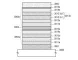
本発明の一態様は、一対の電極間に発光層を有し、発光層は、燐光性化合物、電子輸送
性を有する第1の有機化合物(ホスト材料)、および正孔輸送性を有する第2の有機化合
物(アシスト材料)を少なくとも有し、また、発光層は、第1の発光層と第2の発光層の
積層構造であり、第1の発光層には、第2の発光層よりも第2の有機化合物が多く含まれ
ることを特徴とする発光素子である。また、発光層(第1の発光層および第2の発光層)
において、第1の有機化合物および第2の有機化合物は、励起錯体を形成する組み合わせ
であることを特徴とする。In one embodiment of the present invention, a light-emitting layer is provided between a pair of electrodes, and the light-emitting layer includes a phosphorescent compound, a first electron-transporting organic compound (host material), and a hole-transporting second organic compound. The light-emitting layer has a laminated structure of a first light-emitting layer and a second light-emitting layer, and the first light-emitting layer has more than the second light-emitting layer The light-emitting element is characterized by containing a large amount of the second organic compound. In addition, a light-emitting layer (first light-emitting layer and second light-emitting layer)
3, the first organic compound and the second organic compound are a combination that forms an exciplex.
また、本発明の別の一態様は、陽極と陰極との間に発光層を有し、陽極と発光層との間
に正孔輸送層を有し、陰極と発光層との間に電子輸送層を有し、発光層は、燐光性化合物
、電子輸送性を有する第1の有機化合物、および正孔輸送性を有する第2の有機化合物を
少なくとも含み、かつ正孔輸送層と接して形成された第1の発光層と、燐光性化合物、電
子輸送性を有する第1の有機化合物、および正孔輸送性を有する第2の有機化合物を少な
くとも含み、かつ電子輸送層と接して形成された第2の発光層との積層であり、第1の有
機化合物と第2の有機化合物は励起錯体を形成し、第1の発光層には、第2の発光層より
も第2の有機化合物が多く含まれることを特徴とする発光素子である。In another aspect of the present invention, a light-emitting layer is provided between an anode and a cathode, a hole-transport layer is provided between the anode and the light-emitting layer, and an electron-transport layer is provided between the cathode and the light-emitting layer. The light-emitting layer contains at least a phosphorescent compound, a first organic compound having an electron-transporting property, and a second organic compound having a hole-transporting property, and is formed in contact with the hole-transporting layer. a first light-emitting layer, a phosphorescent compound, a first organic compound having an electron-transporting property, and a second organic compound having a hole-transporting property, and formed in contact with the electron-transporting layer; 2 light-emitting layers, the first organic compound and the second organic compound form an exciplex, and the first light-emitting layer contains more of the second organic compound than the second light-emitting layer. A light-emitting device characterized by comprising:
なお、上記各構成において、第1の有機化合物(ホスト材料)と第2の有機化合物(ア
シスト材料)により形成された励起錯体の発光波長は、第1の有機化合物(ホスト材料)
と第2の有機化合物(アシスト材料)のそれぞれの発光波長(蛍光波長)に比べて、長波
長側に存在することから、励起錯体を形成することにより、第1の有機化合物(ホスト材
料)の蛍光スペクトルや第2の有機化合物(アシスト材料)の蛍光スペクトルを、より長
波長側に位置する発光スペクトルに変換することができる。In each of the above structures, the emission wavelength of the exciplex formed by the first organic compound (host material) and the second organic compound (assisting material) is the same as that of the first organic compound (host material).
and the second organic compound (assisting material) on the longer wavelength side than the emission wavelengths (fluorescence wavelengths) of the first organic compound (host material) and the first organic compound (host material) by forming an exciplex. The fluorescence spectrum or the fluorescence spectrum of the second organic compound (assisting material) can be converted into an emission spectrum positioned on the longer wavelength side.
従って、本発明の一態様である発光素子は、発光層において励起錯体を形成することに
より、第1の有機化合物と第2の有機化合物それぞれの発光波長(蛍光波長)よりも長波
長側に存在する励起錯体の発光スペクトルと、燐光性化合物(ゲスト材料)の吸収スペク
トルとの重なりを利用したエネルギー移動を行うことができ、エネルギー移動効率が高く
、外部量子効率の高い発光素子を実現することができる。Therefore, in the light-emitting element which is one embodiment of the present invention, an exciplex is formed in the light-emitting layer, so that the emission wavelength (fluorescence wavelength) of each of the first organic compound and the second organic compound is present on the longer wavelength side than the emission wavelengths (fluorescence wavelengths) of the first organic compound and the second organic compound. Energy transfer can be performed using the overlap between the emission spectrum of the exciplex and the absorption spectrum of the phosphorescent compound (guest material), and a light-emitting device with high energy transfer efficiency and high external quantum efficiency can be realized. can.
なお、上記構成において、発光層に含まれる燐光性化合物は、第1の発光層に含まれる
物質と第2の発光層に含まれる物質とで同じであっても、異なっていても良い。但し、異
なっている場合には、第1の発光層から得られる発光は、第2の発光層から得られる発光
よりも短波長な光であることを特徴とする。Note that in the above structure, the phosphorescent compound contained in the light-emitting layer may be the same as or different from the substance contained in the first light-emitting layer and the substance contained in the second light-emitting layer. However, when they are different, the light emitted from the first light-emitting layer is characterized by having a shorter wavelength than the light emitted from the second light-emitting layer.
なお、上記構成において、第1の有機化合物のアニオンおよび第2の有機化合物のカチ
オンから励起錯体が形成されることを特徴とする。Note that in the above structure, an exciplex is formed from an anion of the first organic compound and a cation of the second organic compound.
また、上記構成において、燐光性化合物は、有機金属錯体であり、第1の有機化合物は
、主として10-6cm2/Vs以上の電子移動度を有する電子輸送性材料、具体的には
π電子不足型複素芳香族化合物であり、第2の有機化合物は、主として10-6cm2/
Vs以上の正孔移動度を有する正孔輸送性材料、具体的にはπ電子過剰型複素芳香族化合
物または芳香族アミン化合物であることを特徴とする。In the above structure, the phosphorescent compound is an organometallic complex, and the first organic compound is an electron-transporting material having an electron mobility of 10−6 cm2 /Vs or more, specifically π electrons. A deficient heteroaromatic compound, the second organic compound is mainly 10−6 cm2 /
It is characterized by being a hole-transporting material having a hole mobility of Vs or higher, specifically a π-electron-rich heteroaromatic compound or an aromatic amine compound.
また、本発明の一態様は、発光素子を有する発光装置だけでなく、発光装置を有する電
子機器および照明装置も範疇に含めるものである。従って、本明細書中における発光装置
とは、画像表示デバイス、発光デバイス、もしくは光源(照明装置含む)を指す。また、
発光装置にコネクター、例えばFPC(Flexible printed circu
it)もしくはTCP(Tape Carrier Package)が取り付けられた
モジュール、TCPの先にプリント配線板が設けられたモジュール、または発光素子にC
OG(Chip On Glass)方式によりIC(集積回路)が直接実装されたモジ
ュールも全て発光装置に含むものとする。Further, one embodiment of the present invention includes not only a light-emitting device including a light-emitting element but also an electronic device and a lighting device including a light-emitting device. Therefore, the light-emitting device in this specification refers to an image display device, a light-emitting device, or a light source (including a lighting device). again,
A connector such as an FPC (flexible printed circuit) is connected to the light emitting device.
it) or a module with a TCP (Tape Carrier Package) attached, a module with a printed wiring board at the end of the TCP, or a C
All modules in which an IC (integrated circuit) is directly mounted by the OG (Chip On Glass) method are included in the light emitting device.
なお、本発明の一態様である発光素子は、発光層において励起錯体を形成することによ
り、第1の有機化合物と第2の有機化合物それぞれの発光波長(蛍光波長)よりも長波長
側に存在する励起錯体の発光スペクトルと、燐光性化合物(ゲスト材料)の吸収スペクト
ルとの重なりを利用したエネルギー移動を行うことができるため、エネルギー移動効率が
高く、外部量子効率の高い発光素子を実現することができる。Note that in the light-emitting element which is one embodiment of the present invention, an exciplex is formed in the light-emitting layer, so that the emission wavelength (fluorescence wavelength) of each of the first organic compound and the second organic compound is present on the longer wavelength side. Since energy transfer can be performed using the overlap between the emission spectrum of the exciplex and the absorption spectrum of the phosphorescent compound (guest material), a light-emitting device with high energy transfer efficiency and high external quantum efficiency can be realized. can be done.
さらに、本発明の一態様における発光層は、第1の発光層と第2の発光層との積層構造
であり、第1の発光層と第2の発光層は、いずれも電子輸送性を有する第1の有機化合物
(ホスト材料)と、正孔輸送性を有する第2の有機化合物(アシスト材料)とを含み、第
1の発光層は、第2の発光層よりも第2の有機化合物(アシスト材料)が多く含まれる構
成とすることにより、発光層内におけるキャリア(正孔、電子の双方)バランスを向上さ
せ、発光層で形成される励起子を第1の発光層と第2の発光層の界面に分布させることが
できる。これにより、局所的に励起子の密度が高くなることによる発光層の劣化を防止す
ることができる。Furthermore, the light-emitting layer in one embodiment of the present invention has a stacked structure of a first light-emitting layer and a second light-emitting layer, and both the first light-emitting layer and the second light-emitting layer have an electron-transport property. A first organic compound (host material) and a second organic compound (assisting material) having a hole-transporting property are included, and the first light-emitting layer is more likely to contain the second organic compound (host material) than the second light-emitting layer. assist material) in the light-emitting layer, the balance of carriers (both holes and electrons) in the light-emitting layer is improved, and the excitons formed in the light-emitting layer are separated into the first light-emitting layer and the second light-emitting layer. It can be distributed at the interface of the layers. As a result, it is possible to prevent deterioration of the light-emitting layer due to a local increase in exciton density.
以下、本発明の実施の態様について図面を用いて詳細に説明する。但し、本発明は以下
の説明に限定されず、本発明の趣旨及びその範囲から逸脱することなくその形態及び詳細
を様々に変更し得ることが可能である。従って、本発明は以下に示す実施の形態の記載内
容に限定して解釈されるものではない。Hereinafter, embodiments of the present invention will be described in detail with reference to the drawings. However, the present invention is not limited to the following description, and various changes in form and detail can be made without departing from the spirit and scope of the present invention. Therefore, the present invention should not be construed as being limited to the descriptions of the embodiments shown below.
(発光素子における発光の素過程について)
まず、燐光性化合物をゲスト材料として用いる発光素子における発光の一般的な素過程
について説明する。なお、ここでは、励起エネルギーを与える側の分子をホスト分子、励
起エネルギーを受け取る側の分子をゲスト分子と記す。(Regarding Elementary Process of Light Emission in Light Emitting Element)
First, a general elementary process of light emission in a light-emitting element using a phosphorescent compound as a guest material will be described. Note that here, a molecule that gives excitation energy is referred to as a host molecule, and a molecule that receives excitation energy is referred to as a guest molecule.
(1)電子及び正孔(ホール)がゲスト分子において再結合し、ゲスト分子が励起状態
となる場合(直接再結合過程)。(1) When electrons and holes recombine in guest molecules and the guest molecules are in an excited state (direct recombination process).
(1-1)ゲスト分子の励起状態が三重項励起状態のとき
ゲスト分子は燐光を発する。(1-1) When the excited state of the guest molecule is a triplet excited state The guest molecule emits phosphorescence.
(1-2)ゲスト分子の励起状態が一重項励起状態のとき
一重項励起状態のゲスト分子は三重項励起状態に項間交差し、燐光を発する。(1-2) When the Excited State of the Guest Molecule is a Singlet Excited State A guest molecule in a singlet excited state intersystem crosses to a triplet excited state and emits phosphorescence.
つまり、上記(1)の直接再結合過程においては、ゲスト分子の項間交差効率、及び燐
光量子収率さえ高ければ、高い発光効率が得られることになる。なお、ホスト分子のT1
準位はゲスト分子のT1準位よりも高いことが好ましい。That is, in the direct recombination process (1) above, high luminous efficiency can be obtained as long as the intersystem crossing efficiency of the guest molecules and the phosphorescence quantum yield are high. Note that T1 of the host molecule
The level is preferably higher than the T1 level of the guest molecule.
(2)電子及び正孔(ホール)がホスト分子において再結合し、ホスト分子が励起状態
となる場合(エネルギー移動過程)。(2) When electrons and holes recombine in the host molecule and the host molecule is in an excited state (energy transfer process).
(2-1)ホスト分子の励起状態が三重項励起状態のとき
ホスト分子のT1準位がゲスト分子のT1準位よりも高い場合、ホスト分子からゲスト
分子に励起エネルギーが移動し、ゲスト分子が三重項励起状態となる。三重項励起状態と
なったゲスト分子は燐光を発する。なお、ホスト分子のT1準位からゲスト分子の一重項
励起エネルギーの準位(S1準位)へのエネルギー移動は、ホスト分子が燐光発光しない
限り禁制であり、主たるエネルギー移動過程になりにくいため、ここでは省略する。つま
り、下記式(2-1)の通り、ホスト分子の三重項励起状態(3H*)からゲスト分子の
三重項励起状態(3G*)へのエネルギー移動が重要である(式中、1Gはゲスト分子の
一重項基底状態、1Hはホスト分子の一重項基底状態を表す)。(2-1) When the excited state of the host molecule is a triplet excited state When the T1 level of the host molecule is higher than the T1 level of the guest molecule, excitation energy is transferred from the host molecule to the guest molecule, and the guest molecule It becomes a triplet excited state. The guest molecule in the triplet excited state emits phosphorescence. Note that energy transfer from the T1 level of the host molecule to the level of the singlet excitation energy of the guest molecule (S1 level) is prohibited unless the host molecule emits phosphorescence, and is unlikely to be the main energy transfer process. omitted here. That is, as shown in the following formula (2-1), energy transfer from the triplet excited state (3H*) of the host molecule to the triplet excited state (3G*) of the guest molecule is important (wherein 1G is the guest singlet ground state of the molecule, 1H represents the singlet ground state of the host molecule).
3H*+1G → 1H+3G* (2-1) 3H*+1G → 1H+3G* (2-1)
(2-2)ホスト分子の励起状態が一重項励起状態のとき
ホスト分子のS1準位がゲスト分子のS1準位およびT1準位よりも高い場合、ホスト
分子からゲスト分子に励起エネルギーが移動し、ゲスト分子が一重項励起状態又は三重項
励起状態となる。三重項励起状態となったゲスト分子は燐光を発する。また、一重項励起
状態となったゲスト分子は、三重項励起状態に項間交差し、燐光を発する。(2-2) When the excited state of the host molecule is a singlet excited state When the S1 level of the host molecule is higher than the S1 and T1 levels of the guest molecule, excitation energy is transferred from the host molecule to the guest molecule. , the guest molecule becomes a singlet excited state or a triplet excited state. The guest molecule in the triplet excited state emits phosphorescence. Further, the guest molecule in the singlet excited state undergoes intersystem crossing to the triplet excited state and emits phosphorescence.
つまり、下記式(2-2A)の通り、ホスト分子の一重項励起状態(1H*)からゲス
ト分子の一重項励起状態(1G*)へエネルギー移動し、その後項間交差によってゲスト
分子の三重項励起状態(3G*)が生成する過程と、下記式(2-2B)の通り、ホスト
分子の一重項励起状態(1H*)からゲスト分子の三重項励起状態(3G*)へ直接エネ
ルギー移動する過程が考えられる。That is, as shown in the following formula (2-2A), the energy is transferred from the singlet excited state (1H*) of the host molecule to the singlet excited state (1G*) of the guest molecule, and then the triplet of the guest molecule by intersystem crossing. Direct energy transfer from the singlet excited state (1H*) of the host molecule to the triplet excited state (3G*) of the guest molecule as shown in the following formula (2-2B) and the process of generating the excited state (3G*) process can be considered.
1H*+1G → 1H+1G* →(項間交差)→ 1H+3G* (2-2A
)
1H*+1G → 1H+3G* (2-2B)1H*+1G → 1H+1G* → (intersystem crossover) → 1H+3G* (2-2A
)
1H*+1G → 1H+3G* (2-2B)
上記(2)で述べた全てのエネルギー移動過程が効率よく生じれば、ホスト分子の三重
項励起エネルギー及び一重項励起エネルギーの双方が効率よくゲスト分子の三重項励起状
態(3G*)に変換されるため、高効率な発光が可能となる。逆に、ホスト分子からゲス
ト分子に励起エネルギーが移動する前に、ホスト分子自体がその励起エネルギーを光又は
熱として放出して失活してしまうと、発光効率が低下することになる。If all the energy transfer processes described in (2) above occur efficiently, both the triplet excitation energy and the singlet excitation energy of the host molecule are efficiently converted to the triplet excited state (3G*) of the guest molecule. Therefore, highly efficient light emission is possible. Conversely, if the host molecule itself emits its excitation energy as light or heat and is deactivated before the excitation energy is transferred from the host molecule to the guest molecule, the luminous efficiency will decrease.
次に、上述したホスト分子とゲスト分子との分子間のエネルギー移動過程の支配因子に
ついて説明する。分子間のエネルギー移動の機構としては、以下の2つの機構が提唱され
ている。Next, the factors governing the above-described intermolecular energy transfer process between the host molecule and the guest molecule will be described. The following two mechanisms have been proposed as mechanisms of intermolecular energy transfer.
まず、1つ目の機構であるフェルスター機構(双極子-双極子相互作用)は、エネルギ
ー移動に、分子間の直接的接触を必要とせず、ホスト分子及びゲスト分子間の双極子振動
の共鳴現象を通じてエネルギー移動が起こる機構である。双極子振動の共鳴現象によって
ホスト分子がゲスト分子にエネルギーを受け渡し、ホスト分子が基底状態になり、ゲスト
分子が励起状態になる。なお、フェルスター機構の速度定数kh*→gを数式(1)に示
す。First, the Förster mechanism (dipole-dipole interaction), which is the first mechanism, does not require direct contact between molecules for energy transfer, and resonance of dipole vibrations between host and guest molecules It is the mechanism by which energy transfer occurs through phenomena. Due to the resonance phenomenon of dipole vibration, the host molecule transfers energy to the guest molecule, the host molecule becomes the ground state, and the guest molecule becomes the excited state. Note that the rate constant kh*→g of the Förster mechanism is shown in Equation (1).

数式(1)において、νは、振動数を表し、f’h(ν)は、ホスト分子の規格化され
た発光スペクトル(一重項励起状態からのエネルギー移動を論じる場合は蛍光スペクトル
、三重項励起状態からのエネルギー移動を論じる場合は燐光スペクトル)を表し、εg(
ν)は、ゲスト分子のモル吸光係数を表し、Nは、アボガドロ数を表し、nは、媒体の屈
折率を表し、Rは、ホスト分子とゲスト分子の分子間距離を表し、τは、実測される励起
状態の寿命(蛍光寿命や燐光寿命)を表し、cは、光速を表し、φは、発光量子収率(一
重項励起状態からのエネルギー移動を論じる場合は蛍光量子収率、三重項励起状態からの
エネルギー移動を論じる場合は燐光量子収率)を表し、K2は、ホスト分子とゲスト分子
の遷移双極子モーメントの配向を表す係数(0~4)である。なお、ランダム配向の場合
はK2=2/3である。In equation (1), ν represents the vibration frequency, f′h (ν) is the normalized emission spectrum of the host molecule (fluorescence spectrum when discussing energy transfer from the singlet excited state, triplet excitation represents the phosphorescence spectrum when discussing energy transfer from a state, and εg (
ν) represents the molar absorption coefficient of the guest molecule, N represents Avogadro's number, n represents the refractive index of the medium, R represents the intermolecular distance between the host molecule and the guest molecule, and τ represents the measured value. represents the lifetime of the excited state (fluorescence lifetime or phosphorescence lifetime), c represents the speed of light, and φ represents the emission quantum yield (fluorescence quantum yield when discussing energy transfer from the singlet excited state, triplet When discussing energy transfer from an excited state,K2 represents the phosphorescence quantum yield), and K2 is a coefficient (0-4) representing the orientation of the transition dipole moments of the host and guest molecules. In the case of random orientation, K2 =2/3.
次に、2つ目の機構であるデクスター機構(電子交換相互作用)では、ホスト分子とゲ
スト分子が軌道の重なりを生じる接触有効距離に近づき、励起状態のホスト分子の電子と
基底状態のゲスト分子の電子の交換を通じてエネルギー移動が起こる。なお、デクスター
機構の速度定数kh*→gを数式(2)に示す。Next, in the second mechanism, the Dexter mechanism (electron exchange interaction), the host molecule and the guest molecule approach the contact effective distance that causes orbital overlap, and the electrons of the host molecule in the excited state and the guest molecule in the ground state Energy transfer occurs through the exchange of electrons in Note that the rate constant kh*→g of the Dexter mechanism is shown in Equation (2).

数式(2)において、hは、プランク定数であり、K’は、エネルギーの次元を持つ定
数であり、νは、振動数を表し、f’h(ν)は、ホスト分子の規格化された発光スペク
トル(一重項励起状態からのエネルギー移動を論じる場合は蛍光スペクトル、三重項励起
状態からのエネルギー移動を論じる場合は燐光スペクトル)を表し、ε’g(ν)は、ゲ
スト分子の規格化された吸収スペクトルを表し、Lは、実効分子半径を表し、Rは、ホス
ト分子とゲスト分子の分子間距離を表す。In equation (2), h is Planck's constant, K′ is a constant with the dimension of energy, ν represents the vibrational frequency, and f′h (ν) is the normalized represents the emission spectrum (fluorescence spectrum when discussing energy transfer from the singlet excited state, phosphorescence spectrum when discussing energy transfer from the triplet excited state), and ε′g (ν) is the normalized value of the guest molecule. L represents the effective molecular radius, and R represents the intermolecular distance between the host molecule and the guest molecule.
ここで、ホスト分子からゲスト分子へのエネルギー移動効率ΦETは、数式(3)で表
されると考えられる。krは、ホスト分子の発光過程(一重項励起状態からのエネルギー
移動を論じる場合は蛍光、三重項励起状態からのエネルギー移動を論じる場合は燐光)の
速度定数を表し、knは、ホスト分子の非発光過程(熱失活や項間交差)の速度定数を表
し、τは、実測されるホスト分子の励起状態の寿命を表す。Here, the energy transfer efficiency ΦET from the host molecule to the guest molecule is considered to be represented by Equation (3).kr represents the rate constant of the emission process of the host molecule (fluorescence when discussing energy transfer from the singlet excited state, phosphorescence when discussing energy transfer from the triplet excited state), andkn is the host molecule represents the rate constant of the non-radiative process (thermal deactivation and intersystem crossing) of , and τ represents the measured lifetime of the excited state of the host molecule.

数式(3)より、エネルギー移動効率ΦETを高くするためには、エネルギー移動の速
度定数kh*→gを大きくし、他の競合する速度定数kr+kn(=1/τ)が相対的に
小さくなれば良いことがわかる。From Equation (3), in order to increase the energy transfer efficiency ΦET , the energy transfer rate constant kh * → g is increased, and the other competing rate constants kr + kn (= 1/τ) are relatively It can be seen that the smaller the size, the better.
((2-1)のエネルギー移動効率について)
ここでまず、(2-1)のエネルギー移動過程を考えてみる。この場合、フェルスター
型(式(1))は禁制となるため、デクスター型(式(2))のみを考えれば良い。式(
2)によれば、速度定数kh*→gを大きくするにはホスト分子の発光スペクトル(三重
項励起状態からのエネルギー移動を論じているので燐光スペクトル)とゲスト分子の吸収
スペクトル(一重項基底状態から三重項励起状態への直接遷移に相当する吸収)との重な
りが大きい方が良いことがわかる。(Regarding (2-1) energy transfer efficiency)
First, consider the energy transfer process of (2-1). In this case, the Förster type (formula (1)) is prohibited, so only the Dexter type (formula (2)) should be considered. formula(
According to 2), in order to increase the rate constant kh*→g, the emission spectrum of the host molecule (phosphorescence spectrum because the energy transfer from the triplet excited state is discussed) and the absorption spectrum of the guest molecule (singlet basis It can be seen that the larger the overlap with the absorption corresponding to the direct transition from the state to the triplet excited state, the better.
本発明の一態様では、燐光性化合物をゲスト材料として用いるが、燐光性化合物の吸収
スペクトルにおいては、一重項基底状態から三重項励起状態への直接遷移に相当する吸収
が観測される場合があり、それは最も長波長側に現れる吸収帯である。特に発光性のイリ
ジウム錯体では、最も長波長側の吸収帯は、500~600nm付近にブロードな吸収帯
として現れる場合が多い(無論、発光波長によっては、より短波長側やより長波長側に現
れる場合もある)。この吸収帯は、主として、三重項MLCT(Metal to Li
gand Charge Transfer)遷移に由来する。ただし、該吸収帯には三
重項π-π*遷移や一重項MLCT遷移に由来する吸収も一部含まれ、これらが重なって
、吸収スペクトルの最も長波長側にブロードな吸収帯を形成していると考えられる。換言
すれば、最低一重項励起状態と最低三重項励起状態の差は小さく、これらに由来する吸収
が重なって、吸収スペクトルの最も長波長側にブロードな吸収帯を形成していると考えら
れる。したがって、ゲスト材料に、有機金属錯体(特にイリジウム錯体)を用いるときは
、このように最も長波長側に存在するブロードな吸収帯と、ホスト材料の燐光スペクトル
が大きく重なることによって、速度定数kh*→gを大きくし、エネルギー移動効率を高
めることができる。In one embodiment of the present invention, a phosphorescent compound is used as a guest material. In some cases, absorption corresponding to direct transition from a singlet ground state to a triplet excited state is observed in the absorption spectrum of the phosphorescent compound. , which is the absorption band appearing on the longest wavelength side. Especially in luminescent iridium complexes, the absorption band on the longest wavelength side often appears as a broad absorption band near 500 to 600 nm (of course, depending on the emission wavelength, it appears on the shorter or longer wavelength side. In some cases). This absorption band is mainly due to the triplet MLCT (Metal to Li
(gand Charge Transfer) transition. However, the absorption band also includes some absorption derived from triplet π-π* transitions and singlet MLCT transitions, and these overlap to form a broad absorption band on the longest wavelength side of the absorption spectrum. It is thought that there are In other words, it is considered that the difference between the lowest singlet excited state and the lowest triplet excited state is small, and the absorptions derived from these overlap to form a broad absorption band on the longest wavelength side of the absorption spectrum. Therefore, when an organometallic complex (especially an iridium complex) is used as the guest material, the broad absorption band present on the longest wavelength side overlaps greatly with the phosphorescence spectrum of the host material, resulting in a rate constant of kh *→g can be increased to increase energy transfer efficiency.
さらに、通常、ホスト材料には蛍光性化合物を用いるため、燐光寿命(τ)はミリ秒以
上と非常に長い(kr+knが小さい)。これは、三重項励起状態から基底状態(一重項
)への遷移が禁制遷移のためである。数式(3)から、このことはエネルギー移動効率Φ
ETに対して有利に働く。Furthermore, since a fluorescent compound is usually used as the host material, the phosphorescence lifetime (τ) is as long as milliseconds or more (kr +kn is small). This is because the transition from the triplet excited state to the ground state (singlet) is a forbidden transition. From equation (3), this means that the energy transfer efficiency Φ
FavorsET .
以上のことを考慮すると、ホスト材料の三重項励起状態からゲスト材料の三重項励起状
態へのエネルギー移動、すなわち式(2-1)の過程は、ホスト材料の燐光スペクトルと
、ゲスト材料の一重項基底状態から三重項励起状態への直接遷移に相当する吸収スペクト
ルとを重ねさえすれば、総じて起こりやすい傾向にある。Considering the above, the energy transfer from the triplet excited state of the host material to the triplet excited state of the guest material, that is, the process of formula (2-1) can be explained by the phosphorescence spectrum of the host material and the singlet of the guest material. As long as the absorption spectrum corresponding to the direct transition from the ground state to the triplet excited state is superimposed, it tends to occur generally.
((2-2)のエネルギー移動効率について)
次に、(2-2)のエネルギー移動過程を考えてみる。式(2-2A)の過程は、ゲス
ト材料の項間交差効率が影響してしまう。したがって、極限まで発光効率を高めるために
は、式(2-2B)の過程が重要であると考えられる。この場合、デクスター型(式(2
))は禁制となるため、フェルスター型(式(1))のみを考えれば良い。(Regarding (2-2) energy transfer efficiency)
Next, consider the energy transfer process of (2-2). The process of formula (2-2A) is affected by the intersystem crossing efficiency of the guest material. Therefore, it is considered that the process of formula (2-2B) is important for maximizing the luminous efficiency. In this case, the Dexter type (formula (2
)) is forbidden, only the Förster type (formula (1)) should be considered.
式(1)と式(3)からτを消去すると、エネルギー移動効率ΦETは、量子収率φ(
一重項励起状態からのエネルギー移動を論じているので、蛍光量子収率)が高い方が良い
と言える。しかし実際は、さらに重要なファクターとして、ホスト分子の発光スペクトル
(一重項励起状態からのエネルギー移動を論じているので蛍光スペクトル)とゲスト分子
の吸収スペクトル(一重項基底状態から三重項励起状態への直接遷移に相当する吸収)と
の重なりが大きいことも必要である(なお、ゲスト分子のモル吸光係数も高い方が好まし
い)。このことは、ホスト材料の蛍光スペクトルと、ゲスト材料である燐光性化合物の最
も長波長側に現れる吸収帯とが重なることを意味する。Eliminating τ from equations (1) and (3), the energy transfer efficiency ΦET is the quantum yield Φ (
Since we are discussing the energy transfer from the singlet excited state, it can be said that the higher the fluorescence quantum yield, the better. In practice, however, more important factors are the emission spectrum of the host molecule (fluorescence spectrum, since we are discussing energy transfer from the singlet excited state) and the absorption spectrum of the guest molecule (direct transfer from the singlet ground state to the triplet excited state). It is also necessary to have a large overlap with the absorption corresponding to the transition (in addition, it is preferable that the molar absorption coefficient of the guest molecule is also high). This means that the fluorescence spectrum of the host material overlaps with the absorption band appearing on the longest wavelength side of the phosphorescent compound as the guest material.
しかしながら、このことを実現することは、従来は非常に困難であった。なぜならば、
上述した(2-1)の過程と(2-2)の過程の双方を効率よく行おうとすると、上述の
議論から、ホスト材料の燐光スペクトルだけでなく、蛍光スペクトルをもゲスト材料の最
も長波長側の吸収帯と重ねるように設計しなければならないためである。換言すれば、ホ
スト材料の蛍光スペクトルが、燐光スペクトルと同じような位置に来るようにホスト材料
を設計しなければならないということになる。However, it has been very difficult in the past to achieve this. because,
When trying to efficiently perform both the above-mentioned process (2-1) and process (2-2), from the above discussion, not only the phosphorescence spectrum of the host material but also the fluorescence spectrum has the longest wavelength of the guest material. This is because it must be designed so as to overlap with the side absorption bands. In other words, the host material must be designed so that the fluorescence spectrum of the host material is positioned similarly to the phosphorescence spectrum.
ところが、一般に、S1準位とT1準位は大きく異なる(S1準位>T1準位)ため、
蛍光の発光波長と燐光の発光波長も大きく異なる(蛍光の発光波長<燐光の発光波長)。
例えば、燐光性化合物を用いた発光素子において、ホスト材料として良く用いられる4,
4’-ジ(N-カルバゾリル)ビフェニル(略称:CBP)は、500nm付近に燐光ス
ペクトルを有するが、一方で蛍光スペクトルは400nm付近であり、100nmもの隔
たりがある。この例から考えてみても、ホスト材料の蛍光スペクトルが燐光スペクトルと
同じような位置に来るようにホスト材料を設計することは、極めて困難である。したがっ
て、ホスト材料の一重項励起状態からのゲスト材料へのエネルギー移動効率の向上は、と
ても重要である。However, since the S1 level and the T1 level are generally significantly different (S1 level>T1 level),
The fluorescence emission wavelength and the phosphorescence emission wavelength are also significantly different (fluorescence emission wavelength<phosphorescence emission wavelength).
For example, 4, which is often used as a host material in a light-emitting device using a phosphorescent compound,
4′-di(N-carbazolyl)biphenyl (abbreviation: CBP) has a phosphorescence spectrum around 500 nm, while a fluorescence spectrum is around 400 nm, separated by as much as 100 nm. Considering this example, it is extremely difficult to design the host material so that the fluorescence spectrum of the host material is located at the same position as the phosphorescence spectrum. Therefore, improving the efficiency of energy transfer from the singlet excited state of the host material to the guest material is very important.
従って、本発明の一態様は、このようなホスト材料の一重項励起状態からのゲスト材料
へのエネルギー移動効率に関する問題点を克服できる、有用な手法を提供するものである
。以下に、その具体的な態様を説明する。Accordingly, one aspect of the present invention provides a useful technique that can overcome such problems related to efficiency of energy transfer from the singlet excited state of the host material to the guest material. Specific aspects thereof will be described below.
(実施の形態1)
本実施の形態では、本発明の一態様である発光素子を構成する上での概念および具体的
な発光素子の構成について説明する。なお、本発明の一態様である発光素子は、一対の電
極間に発光層を含むEL層を挟んで形成されており、発光層は、燐光性化合物であるゲス
ト材料と、第1の有機化合物と、第2の有機化合物とを含んで形成される。(Embodiment 1)
In this embodiment, a concept of forming a light-emitting element that is one embodiment of the present invention and a specific structure of the light-emitting element will be described. Note that the light-emitting element which is one embodiment of the present invention includes an EL layer including a light-emitting layer sandwiched between a pair of electrodes. and a second organic compound.
まず、本発明の一例である発光素子の素子構造について、図1(A)により説明する。 First, an element structure of a light-emitting element which is an example of the present invention is described with reference to FIG.
図1(A)に示す素子構造は、一対の電極(陽極101、陰極102)間に発光層10
6を含むEL層103が挟まれており、EL層103は、陽極101側から正孔(ホール
)注入層104、正孔(ホール)輸送層105、発光層106(106a、106b)、
電子輸送層107、電子注入層108等が順次積層された構造を有する。In the element structure shown in FIG. 1A, a light-emitting
6 is sandwiched therebetween, and the
It has a structure in which an
また、本発明の一態様における発光層106は、図1(A)に示すようにゲスト材料で
ある燐光性化合物109と、第1の有機化合物110と、第2の有機化合物111とを含
む層であり、第1の有機化合物110としては、主として10-6cm2/Vs以上の電
子移動度を有する電子輸送性材料を用い、第2の有機化合物111としては、主として1
0-6cm2/Vs以上の正孔移動度を有する正孔(ホール)輸送性材料を用いることと
する。また、本明細書中では、第1の有機化合物110をホスト材料と呼び、第2の有機
化合物111をアシスト材料と呼ぶこととする。Further, the light-emitting
A hole-transporting material having a hole mobility of 0−6 cm2 /Vs or more is used. Also, in this specification, the first
なお、上記構成において、第1の有機化合物(ホスト材料)110及び第2の有機化合
物(アシスト材料)111のそれぞれの三重項励起エネルギーの準位(T1準位)は、燐
光性化合物(ゲスト材料)109のT1準位よりも高いことが好ましい。第1の有機化合
物110(又は第2の有機化合物111)のT1準位が燐光性化合物109のT1準位よ
りも低いと、発光に寄与する燐光性化合物109の三重項励起エネルギーを第1の有機化
合物110(又は第2の有機化合物111)が消光(クエンチ)してしまい、発光効率の
低下を招くためである。In the above configuration, the triplet excitation energy level (T1 level) of each of the first organic compound (host material) 110 and the second organic compound (assist material) 111 corresponds to the phosphorescent compound (guest material). ) above the T1 level of 109. When the T1 level of the first organic compound 110 (or the second organic compound 111) is lower than the T1 level of the
また、本発明の一態様における発光層106は、発光層106中に含まれる第2の有機
化合物(アシスト材料)111の割合が異なる発光層が積層された構造であることを特徴
とする。具体的には、図1(A)に示すように、発光層106が第1の発光層106aと
第2の発光層106bとの積層構造であり、第1の発光層106aにおいて第2の有機化
合物(アシスト材料)111が含まれる割合は、第2の発光層106bにおいて第2の有
機化合物(アシスト材料)111が含まれる割合よりも多いことを特徴とする。Further, the light-emitting
さらに、発光層106を構成する第1の発光層106aおよび第2の発光層106bの
それぞれについて、第1の有機化合物(ホスト材料)110および第2の有機化合物(ア
シスト材料)111が含まれる割合については、どちらが多くても良く、本発明では、ど
ちらの場合も含めることとする。Further, the first organic compound (host material) 110 and the second organic compound (assist material) 111 are contained in each of the first
なお、上記構造の第1の発光層106aにおいて、正孔(ホール)輸送性材料である第
2の有機化合物(アシスト材料)111の比率が少ないと、発光領域が第1の発光層10
6aの陽極側(正孔輸送層105側)に偏ることになる。一方、第1の発光層106a、
第2の発光層106b双方における第2の有機化合物(アシスト材料)111が多くなり
すぎると、キャリア(正孔、電子の双方)が発光層106を突き抜けやすくなってしまい
、再結合効率が低下してしまう。しかし、図1(A)にて述べた本発明の一態様の構成と
することにより、第1の発光層106aの正孔輸送性は第2の発光層106bの正孔輸送
性に比べて相対的に高まり、電子輸送性はその逆になるため、励起子は第1の発光層10
6aと第2の発光層106bの界面を中心に、偏ることなく、かつ発光層106内から逸
脱することなく分布させることができる。その結果、発光層106内部での励起子の偏り
を防ぐことができ、励起子の密度が高くなることによる発光層106の劣化を防止するこ
とができる。また、発光層106からキャリアが突き抜けることを防げるため、発光効率
を高く保つことができる。In addition, in the first light-emitting
It is biased toward the anode side of 6a (the
If the amount of the second organic compound (assisting material) 111 in both the second
It can be distributed around the interface between 6a and the second light-emitting
ここで、上記第1の発光層106aおよび第2の発光層106bのいずれにおいても第
1の有機化合物(ホスト材料)110と第2の有機化合物(アシスト材料)111とは、
励起錯体(exciplex:エキサイプレックスとも言う)を形成する組み合わせであ
ることを特徴とする。また、形成された励起錯体の発光波長は、第1の有機化合物(ホス
ト材料)110と第2の有機化合物(アシスト材料)111のそれぞれの発光波長(蛍光
波長)に比べて、長波長側に存在することから、第1の有機化合物(ホスト材料)110
の蛍光スペクトルや第2の有機化合物(アシスト材料)111の蛍光スペクトルを、より
長波長側に位置する発光スペクトルに変換することができる。Here, the first organic compound (host material) 110 and the second organic compound (assist material) 111 in both the first light-emitting
It is characterized by being a combination that forms an exciplex. Further, the emission wavelength of the formed exciplex is on the longer wavelength side than the emission wavelengths (fluorescence wavelengths) of the first organic compound (host material) 110 and the second organic compound (assist material) 111, respectively. Since it is present, the first organic compound (host material) 110
, and the fluorescence spectrum of the second organic compound (assisting material) 111 can be converted into an emission spectrum positioned on the longer wavelength side.
このことは、図1(B)に示すように第1の有機化合物110(又は第2の有機化合物
111)の蛍光スペクトルが、たとえ燐光性化合物(ゲスト材料)109の最も長波長側
に位置する吸収帯に比べて短波長側に位置し、燐光性化合物(ゲスト材料)109の最も
長波長側に位置する吸収帯との重なりがなかったとしても、励起錯体を形成することで、
その重なりを大きくできることを意味する。このことにより、上述した式(2-2B)の
エネルギー移動効率を高めることができる。This means that the fluorescence spectrum of the first organic compound 110 (or the second organic compound 111) is located on the longest wavelength side of the phosphorescent compound (guest material) 109, as shown in FIG. Even if there is no overlap with the absorption band of the phosphorescent compound (guest material) 109 which is located on the short wavelength side compared to the absorption band and is located on the longest wavelength side, by forming an exciplex,
It means that the overlap can be increased. As a result, the energy transfer efficiency of formula (2-2B) described above can be enhanced.
さらに、励起錯体は一重項励起エネルギーと三重項励起エネルギーの差が極めて小さい
と考えられる。換言すれば、励起錯体の一重項状態からの発光スペクトルと三重項状態か
らの発光スペクトルは、極めて近接することになる。したがって、上述したように励起錯
体の発光スペクトル(一般には、励起錯体の一重項状態からの発光スペクトル)を燐光性
化合物の最も長波長側に位置する吸収帯に重ねるよう設計した場合、励起錯体の三重項状
態からの発光スペクトル(常温では観測されず、低温でも観測されない場合が多い)も、
燐光性化合物の最も長波長側に位置する吸収帯に重なることになる。つまり、一重項励起
状態からのエネルギー移動((2-2))だけでなく、三重項励起状態からのエネルギー
移動((2-1))の効率も高まり、結果的に、一重項・三重項の双方を効率よく発光に
変換することができる。Furthermore, exciplexes are considered to have a very small difference between singlet and triplet excitation energies. In other words, the emission spectrum from the singlet state and the emission spectrum from the triplet state of the exciplex are very close to each other. Therefore, as described above, when the emission spectrum of the exciplex (generally, the emission spectrum from the singlet state of the exciplex) is designed to overlap the absorption band located on the longest wavelength side of the phosphorescent compound, The emission spectrum from the triplet state (not observed at room temperature and often not observed at low temperatures) is also
It overlaps with the absorption band located on the longest wavelength side of the phosphorescent compound. In other words, not only the energy transfer from the singlet excited state ((2-2)), but also the efficiency of energy transfer from the triplet excited state ((2-1)) is increased, and as a result, singlet/triplet can be efficiently converted into luminescence.
そこで、実際に励起錯体がこのような特性を有しているかどうかに関し、以下では、分
子軌道計算を用いて検証した。一般に、複素芳香族化合物と芳香族アミンとの組み合わせ
は、芳香族アミンの最低空分子軌道(LUMO:Lowest Unoccupied
Molecular Orbital)準位に比べて深い複素芳香族化合物のLUMO準
位(電子が入りやすい性質)と複素芳香族化合物の最高被占有軌道(HOMO:High
est Occupied Molecular Orbital)準位に比べて浅い芳
香族アミンのHOMO準位(ホールが入りやすい性質)の影響で、励起錯体を形成するこ
とが多い。そこで、本発明の一態様における第1の有機化合物110のモデルとして複素
芳香族化合物のLUMOを構成する代表的な骨格のジベンゾ[f,h]キノキサリン(略
称:DBq)を用い、本発明の一態様における第2の有機化合物111のモデルとして芳
香族アミンのHOMOを構成する代表的な骨格のトリフェニルアミン(略称:TPA)を
用い、これらを組み合わせて計算を行った。Therefore, in the following, molecular orbital calculations were used to verify whether the exciplex actually has such characteristics. In general, the combination of a heteroaromatic compound and an aromatic amine is the lowest unoccupied molecular orbital (LUMO) of the aromatic amine.
The LUMO level of heteroaromatic compounds (property where electrons easily enter) and the highest occupied orbital of heteroaromatic compounds (HOMO: High
An exciplex is often formed under the influence of the HOMO level of aromatic amines (the property that holes easily enter) that is shallower than the (est Occupied Molecular Orbital) level. Therefore, as a model of the first
まず、DBq(略称)一分子とTPA(略称)一分子の最低励起一重項状態(S1)と
最低励起三重項状態(T1)における最適分子構造及び励起エネルギーを、時間依存密度
汎関数法(TD-DFT)を用いて計算した。さらに、DBq(略称)とTPA(略称)
の二量体についても励起エネルギーを計算した。First, the optimal molecular structures and excitation energies in the lowest excited singlet state (S1) and the lowest excited triplet state (T1) of one molecule of DBq (abbreviation) and one molecule of TPA (abbreviation) were analyzed by time-dependent density functional theory (TD). -DFT). In addition, DBq (abbreviation) and TPA (abbreviation)
We also calculated the excitation energy for the dimer of
DFT(密度汎関数法)の全エネルギーはポテンシャルエネルギー、電子間静電エネル
ギー、電子の運動エネルギー、及び、複雑な電子間の相互作用を全て含む交換相関エネル
ギーの和で表される。DFTでは、交換相関相互作用を電子密度で表現された一電子ポテ
ンシャルの汎関数(関数の関数の意)で近似しているため、計算は高速かつ高精度である
。ここでは、混合汎関数であるB3LYPを用いて、交換と相関エネルギーに係る各パラ
メータの重みを規定した。The total energy of DFT (Density Functional Theory) is represented by the sum of potential energy, electrostatic energy between electrons, kinetic energy of electrons, and exchange-correlation energy including all complex interactions between electrons. In DFT, since the exchange-correlation interaction is approximated by a functional of one-electron potential expressed by electron density, the calculation is fast and highly accurate. Here, B3LYP, which is a mixed functional, is used to define the weight of each parameter related to the exchange and correlation energies.
また、基底関数として、6-311(それぞれの原子価軌道に三つの短縮関数を用いた
triple split valence基底系の基底関数)を全ての原子に適用した
。As a basis function, 6-311 (a basis function of a triple split valence basis set using three shortening functions for each valence orbital) was applied to all atoms.
上述の基底関数により、例えば、水素原子であれば、1s~3sの軌道が考慮され、ま
た、炭素原子であれば、1s~4s、2p~4pの軌道が考慮されることになる。さらに
、計算精度向上のため、分極基底系として、水素原子にはp関数を、水素原子以外にはd
関数を加えた。According to the basis functions described above, for example, 1s to 3s orbitals are considered for hydrogen atoms, and 1s to 4s and 2p to 4p orbitals are considered for carbon atoms. Furthermore, in order to improve the calculation accuracy, the polarization basis set is a p-function for hydrogen atoms and a d-function for non-hydrogen atoms.
added a function.
なお、量子化学計算プログラムとしては、Gaussian 09を使用した。計算は
、ハイパフォーマンスコンピュータ(SGI社製、Altix4700)を用いて行った
。Gaussian 09 was used as a quantum chemical calculation program. Calculations were performed using a high-performance computer (SGI Altix4700).
まず、DBq(略称)一分子、TPA(略称)一分子、及びDBq(略称)とTPA(
略称)の二量体に関し、HOMO準位及びLUMO準位を算出した。HOMO準位及びL
UMO準位を図2に、HOMO及びLUMOの分布を図3に、それぞれ示す。First, DBq (abbreviation) one molecule, TPA (abbreviation) one molecule, and DBq (abbreviation) and TPA (
The HOMO level and the LUMO level were calculated for the dimer of (abbreviation). HOMO level and L
The UMO levels are shown in FIG. 2, and the HOMO and LUMO distributions are shown in FIG.
図3(A1)に、DBq(略称)一分子のLUMOの分布を示し、図3(A2)に、D
Bq(略称)一分子のHOMOの分布を示し、図3(B1)に、TPA(略称)一分子の
LUMOの分布を示し、図3(B2)に、TPA(略称)一分子のHOMOの分布を示し
、図3(C1)に、DBq(略称)とTPA(略称)の二量体のLUMOの分布を示し、
図3(C2)に、DBq(略称)とTPA(略称)の二量体のHOMOの分布を示す。FIG. 3(A1) shows the LUMO distribution of one DBq (abbreviation) molecule, and FIG. 3(A2) shows D
Bq (abbreviation) shows the HOMO distribution of one molecule, FIG. 3 (B1) shows the LUMO distribution of TPA (abbreviation) one molecule, and FIG. 3 (B2) shows the HOMO distribution of one TPA (abbreviation) molecule. , and FIG. 3 (C1) shows the LUMO distribution of the dimer of DBq (abbreviation) and TPA (abbreviation),
FIG. 3 (C2) shows the HOMO distribution of the dimer of DBq (abbreviation) and TPA (abbreviation).
図2に示すように、DBq(略称)とTPA(略称)の二量体は、TPA(略称)のL
UMO準位に比べて深い(低い)DBq(略称)のLUMO準位(-1.99eV)と、
DBqのHOMO準位に比べて浅い(高い)TPA(略称)のHOMO準位(-5.21
eV)との影響で、DBq(略称)とTPA(略称)の励起錯体を形成することが示唆さ
れる。実際に図3からわかるように、DBq(略称)とTPA(略称)の二量体のLUM
OはDBq(略称)側に、HOMOはTPA(略称)側に分布している。As shown in FIG. 2, the dimer of DBq (abbreviation) and TPA (abbreviation) is L
A DBq (abbreviation) LUMO level (−1.99 eV) that is deeper (lower) than the UMO level,
The HOMO level of TPA (abbreviation) is shallower (higher) than the HOMO level of DBq (-5.21
eV), it is suggested that an exciplex of DBq (abbreviation) and TPA (abbreviation) is formed. As can be seen from FIG. 3, the LUM of the dimer of DBq (abbreviation) and TPA (abbreviation)
O is distributed on the DBq (abbreviation) side, and HOMO is distributed on the TPA (abbreviation) side.
次に、DBq(略称)一分子のS1準位とT1準位における最適分子構造から得られた
励起エネルギーを示す。ここで、S1準位とT1準位の励起エネルギーは、DBq(略称
)一分子が発する蛍光と燐光の波長にそれぞれ相当する。DBq(略称)一分子のS1準
位の励起エネルギーは、3.294eVであり、蛍光波長は、376.4nmであった。
また、DBq(略称)一分子のT1準位の励起エネルギーは、2.460eVであり、燐
光波長は、504.1nmであった。Next, the excitation energies obtained from the optimum molecular structure at the S1 level and the T1 level of one molecule of DBq (abbreviation) are shown. Here, the excitation energies of the S1 level and the T1 level correspond to the wavelengths of fluorescence and phosphorescence emitted by one DBq (abbreviation) molecule, respectively. The excitation energy of the S1 level of one DBq (abbreviation) molecule was 3.294 eV, and the fluorescence wavelength was 376.4 nm.
In addition, the excitation energy of the T1 level of one molecule of DBq (abbreviation) was 2.460 eV, and the phosphorescence wavelength was 504.1 nm.
また、TPA(略称)一分子のS1準位とT1準位における最適分子構造から得られた
励起エネルギーを示す。ここで、S1準位とT1準位の励起エネルギーは、TPA(略称
)一分子が発する蛍光と燐光の波長にそれぞれ相当する。TPA(略称)一分子のS1準
位の励起エネルギーは、3.508eVであり、蛍光波長は、353.4nmであった。
また、TPA(略称)一分子のT1準位の励起エネルギーは、2.610eVであり、燐
光波長は、474.7nmであった。In addition, the excitation energy obtained from the optimum molecular structure at the S1 level and T1 level of one molecule of TPA (abbreviation) is shown. Here, the excitation energies of the S1 level and the T1 level respectively correspond to the wavelengths of fluorescence and phosphorescence emitted by one molecule of TPA (abbreviation). The excitation energy of the S1 level of one molecule of TPA (abbreviation) was 3.508 eV, and the fluorescence wavelength was 353.4 nm.
In addition, the excitation energy of the T1 level of one molecule of TPA (abbreviation) was 2.610 eV, and the phosphorescence wavelength was 474.7 nm.
さらに、DBq(略称)とTPA(略称)の二量体のS1準位とT1準位における最適
分子構造から得られた励起エネルギーを示す。S1準位とT1準位の励起エネルギーは、
DBq(略称)とTPA(略称)の二量体が発する蛍光と燐光の波長にそれぞれ相当する
。DBq(略称)とTPA(略称)の二量体のS1準位の励起エネルギーは、2.036
eVであり、蛍光波長は、609.1nmであった。また、DBq(略称)とTPA(略
称)の二量体のT1準位の励起エネルギーは、2.030eVであり、燐光波長は、61
0.0nmであった。Furthermore, the excitation energies obtained from the optimal molecular structures at the S1 and T1 levels of the dimer of DBq (abbreviation) and TPA (abbreviation) are shown. The excitation energies of the S1 level and the T1 level are
These correspond to the wavelengths of fluorescence and phosphorescence emitted by a dimer of DBq (abbreviation) and TPA (abbreviation), respectively. The excitation energy of the S1 level of the dimer of DBq (abbreviation) and TPA (abbreviation) is 2.036
eV, and the fluorescence wavelength was 609.1 nm. In addition, the excitation energy of the T1 level of the dimer of DBq (abbreviation) and TPA (abbreviation) is 2.030 eV, and the phosphorescence wavelength is 61
It was 0.0 nm.
以上のことから、DBq(略称)一分子、TPA(略称)一分子のいずれにおいても、
燐光波長が100nm近く長波長シフトしていることがわかる。これは、上述したCBP
(略称)(実測値)と同様の傾向であり、計算の妥当性を支持する結果である。From the above, in either one molecule of DBq (abbreviation) or one molecule of TPA (abbreviation),
It can be seen that the phosphorescence wavelength is shifted to a longer wavelength by approximately 100 nm. This is the CBP
(Abbreviation) This is the same trend as (actual measurement), and is a result that supports the validity of the calculation.
一方、DBq(略称)とTPA(略称)の二量体の蛍光波長は、DBq(略称)一分子
やTPA(略称)一分子の蛍光波長に比べ、より長波長側に存在することがわかる。DB
q(略称)とTPA(略称)の二量体の蛍光波長と燐光波長の差はわずか0.9nmであ
り、ほぼ同じ波長であることがわかる。On the other hand, it can be seen that the fluorescence wavelength of the dimer of DBq (abbreviation) and TPA (abbreviation) exists on the longer wavelength side than the fluorescence wavelengths of one molecule of DBq (abbreviation) and one molecule of TPA (abbreviation). database
The difference between the fluorescence wavelength and the phosphorescence wavelength of the q (abbreviation) and TPA (abbreviation) dimers is only 0.9 nm, indicating that they are almost the same wavelength.
この結果から、励起錯体は一重項励起エネルギーと三重項励起エネルギーをほぼ同じエ
ネルギーに集約することができると言える。したがって、上述したように、励起錯体はそ
の一重項状態、及び三重項状態の双方から、燐光性化合物に対して効率よくエネルギー移
動できることが示唆された。From this result, it can be said that the exciplex can concentrate the singlet excitation energy and the triplet excitation energy into almost the same energy. Therefore, as described above, it was suggested that the exciplex can efficiently transfer energy from both its singlet state and triplet state to the phosphorescent compound.
このように、本発明の一態様である発光素子は、発光層において形成された励起錯体の
発光スペクトルと燐光性化合物(ゲスト材料)の吸収スペクトルとの重なりを利用して、
エネルギー移動をするため、エネルギー移動効率が高い。したがって、外部量子効率の高
い発光素子を実現することができる。As described above, the light-emitting element of one embodiment of the present invention utilizes the overlap between the emission spectrum of the exciplex formed in the light-emitting layer and the absorption spectrum of the phosphorescent compound (guest material),
Energy transfer efficiency is high. Therefore, a light-emitting device with high external quantum efficiency can be realized.
また、励起錯体は励起状態でのみ存在するため、エネルギーを吸収できる基底状態が存
在しない。したがって、燐光性化合物(ゲスト材料)の一重項励起状態及び三重項励起状
態から励起錯体へのエネルギー移動により燐光性化合物(ゲスト材料)109が発光する
前に失活する(すなわち発光効率を損なう)という現象は、原理的に生じないと考えられ
る。このことも、外部量子効率を高くできる一因である。In addition, since an exciplex exists only in an excited state, there is no ground state that can absorb energy. Therefore, energy transfer from the singlet excited state and triplet excited state of the phosphorescent compound (guest material) to the exciplex causes the phosphorescent compound (guest material) 109 to be deactivated before it emits light (that is, the luminous efficiency is impaired). This phenomenon is considered not to occur in principle. This is also one of the reasons why the external quantum efficiency can be increased.
なお、上述した励起錯体は、励起状態における異種分子間の相互作用によって形成され
る。また、励起錯体は、比較的深いLUMO準位をもつ材料と、浅いHOMO準位をもつ
材料との間で形成しやすいことが一般に知られている。Note that the above-described exciplex is formed by interaction between different molecules in an excited state. Further, it is generally known that an exciplex is easily formed between a material having a relatively deep LUMO level and a material having a shallow HOMO level.
励起錯体の発光波長は、HOMO準位とLUMO準位間のエネルギー差に依存する。大
まかな傾向として、エネルギー差が大きいと発光波長は短くなり、エネルギー差が小さい
と発光波長は長くなる。The emission wavelength of an exciplex depends on the energy difference between the HOMO and LUMO levels. As a general trend, the larger the energy difference, the shorter the emission wavelength, and the smaller the energy difference, the longer the emission wavelength.
従って、本実施の形態における第1の有機化合物(ホスト材料)110と第2の有機化
合物(アシスト材料)111のHOMO準位及びLUMO準位は、それぞれ異なる。具体
的には、第1の有機化合物110のHOMO準位<第2の有機化合物111のHOMO準
位<第1の有機化合物110のLUMO準位<第2の有機化合物111のLUMO準位と
いう順でエネルギー準位が異なる(図4参照)。Therefore, the HOMO level and the LUMO level of the first organic compound (host material) 110 and the second organic compound (assist material) 111 in this embodiment are different. Specifically, the order is HOMO level of the first
そして、この2つの有機化合物により励起錯体が形成された場合、励起錯体のLUMO
準位は、第1の有機化合物(ホスト材料)110に由来し、HOMO準位は、第2の有機
化合物(アシスト材料)111に由来する(図4参照)。したがって、励起錯体のエネル
ギー差は、第1の有機化合物(ホスト材料)110のエネルギー差、及び第2の有機化合
物(アシスト材料)111のエネルギー差よりも小さくなる。つまり、第1の有機化合物
(ホスト材料)110と第2の有機化合物(アシスト材料)111のそれぞれの発光波長
に比べて、励起錯体の発光波長は長波長となる。Then, when an exciplex is formed by these two organic compounds, the LUMO of the exciplex
The level originates from the first organic compound (host material) 110, and the HOMO level originates from the second organic compound (assist material) 111 (see FIG. 4). Therefore, the energy difference of the exciplex is smaller than the energy difference of the first organic compound (host material) 110 and the energy difference of the second organic compound (assist material) 111 . That is, the emission wavelength of the exciplex is longer than the emission wavelengths of the first organic compound (host material) 110 and the second organic compound (assist material) 111 .
なお、本発明の一態様における励起錯体の形成過程には、以下の2つの過程が考えられ
る。Note that the formation process of an exciplex in one embodiment of the present invention includes the following two processes.
1つ目の形成過程は、第1の有機化合物(ホスト材料)及び第2の有機化合物(アシス
ト材料)がキャリアを持った状態(カチオン又はアニオン)から、励起錯体を形成する形
成過程である。The first formation process is a formation process in which an exciplex is formed from a state in which the first organic compound (host material) and the second organic compound (assist material) have carriers (cations or anions).
一般には、電子及び正孔(ホール)がホスト材料中で再結合した場合、励起状態のホス
ト材料からゲスト材料に励起エネルギーが移動し、ゲスト材料が励起状態に至り、発光す
るが、ホスト材料からゲスト材料に励起エネルギーが移動する前に、ホスト材料自体が発
光する、又は励起エネルギーが熱エネルギーとなることで、励起エネルギーの一部を失活
してしまう。特に、ホスト材料が一重項励起状態である場合は、(2-2)で述べたよう
にエネルギー移動が生じにくい。このような励起エネルギーの失活は、発光素子の寿命の
低下につながる要因の一つである。In general, when electrons and holes recombine in the host material, excitation energy is transferred from the host material in an excited state to the guest material, and the guest material becomes excited and emits light. Before the excitation energy is transferred to the guest material, the host material itself emits light or the excitation energy becomes thermal energy, so that part of the excitation energy is deactivated. In particular, when the host material is in a singlet excited state, energy transfer is difficult to occur as described in (2-2). Such deactivation of excitation energy is one of the factors leading to shortening of the life of the light-emitting element.
しかし、本発明の一態様においては、第1の有機化合物(ホスト材料)及び第2の有機
化合物(アシスト材料)がキャリアを持った状態(カチオン又はアニオン)から、励起錯
体を形成するため、第1の有機化合物(ホスト材料)の一重項励起子の形成を抑制するこ
とができる。つまり、一重項励起子を形成することなく、直接励起錯体を形成する過程が
存在しうる。これにより、上記一重項励起エネルギーの失活も抑制することができる。し
たがって、寿命が長い発光素子を実現することができる。However, in one embodiment of the present invention, since the first organic compound (host material) and the second organic compound (assist material) form an exciplex from a state (cation or anion) having carriers, The formation of singlet excitons in the organic compound (host material) of 1 can be suppressed. That is, there may be a process of forming an exciplex directly without forming a singlet exciton. As a result, deactivation of the singlet excitation energy can also be suppressed. Therefore, a long-life light-emitting element can be realized.
例えば、第1の有機化合物110が、電子輸送性材料の中でも電子(キャリア)を捕獲
しやすい性質を有する(LUMO準位の深い)電子トラップ性の化合物であり、第2の有
機化合物111が、正孔輸送性の材料の中でもホール(キャリア)を捕獲しやすい性質を
有する(HOMO準位の浅い)ホールトラップ性の化合物である場合には、第1の有機化
合物のアニオンと第2の有機化合物のカチオンから、直接励起錯体が形成されることにな
る。このような過程で形成される励起錯体のことを特にエレクトロプレックス(elec
troplex)と呼ぶこととする。このようにして第1の有機化合物(ホスト材料)の
一重項励起状態の発生を抑制し、エレクトロプレックスから燐光性化合物(ゲスト材料)
にエネルギー移動を行うことにより、発光効率が高い発光素子が得られる。なお、この場
合、第1の有機化合物(ホスト材料)の三重項励起状態の発生も同様に抑制され、直接励
起錯体が形成されるため、励起錯体から燐光性化合物(ゲスト材料)にエネルギー移動す
ると考えられる。For example, the first
troplex). In this way, the generation of the singlet excited state of the first organic compound (host material) is suppressed, and the phosphorescent compound (guest material) is removed from the electroplex.
A light-emitting element with high luminous efficiency can be obtained by performing energy transfer to the . In this case, the generation of the triplet excited state of the first organic compound (host material) is similarly suppressed, and an exciplex is directly formed. Conceivable.
2つ目の形成過程は、第1の有機化合物(ホスト材料)及び第2の有機化合物(アシス
ト材料)の一方が一重項励起子を形成した後、基底状態の他方と相互作用して励起錯体を
形成する素過程である。エレクトロプレックスとは異なり、この場合は一旦、第1の有機
化合物(ホスト材料)又は第2の有機化合物(アシスト材料)の一重項励起状態が生成し
てしまうが、これは速やかに励起錯体に変換されるため、やはり一重項励起エネルギーの
失活を抑制することができる。したがって、第1の有機化合物(ホスト材料)又は第2の
有機化合物(アシスト材料)が励起エネルギーを失活することを抑制することができる。
なお、この場合、ホスト材料の三重項励起状態も同様に、速やかに励起錯体に変換され、
励起錯体から燐光性化合物(ゲスト材料)にエネルギー移動すると考えられる。In the second formation process, one of the first organic compound (host material) and the second organic compound (assist material) forms a singlet exciton and then interacts with the other in the ground state to form an exciplex. is the elementary process of forming Unlike electroplex, in this case, the singlet excited state of the first organic compound (host material) or the second organic compound (assist material) is generated once, but it is quickly converted to an exciplex. Therefore, deactivation of singlet excitation energy can be suppressed. Therefore, it is possible to suppress deactivation of the excitation energy of the first organic compound (host material) or the second organic compound (assist material).
In this case, the triplet excited state of the host material is also rapidly converted to an exciplex,
It is believed that energy is transferred from the exciplex to the phosphorescent compound (guest material).
なお、第1の有機化合物(ホスト材料)が電子トラップ性の化合物であり、一方で第2
の有機化合物(アシスト材料)がホールトラップ性の化合物であり、これら化合物のHO
MO準位の差、及びLUMO準位の差が大きい場合(具体的には差が0.3eV以上)、
電子は選択的に第1の有機化合物(ホスト材料)に入り、ホールは選択的に第2の有機化
合物(アシスト材料)に入る。この場合、一重項励起子を経て励起錯体が形成される過程
よりも、エレクトロプレックスが形成される過程の方が優先されると考えられる。Note that the first organic compound (host material) is an electron-trapping compound, while the second
is a hole-trapping compound, and the HO of these compounds
When the MO level difference and the LUMO level difference are large (specifically, the difference is 0.3 eV or more),
Electrons selectively enter the first organic compound (host material) and holes selectively enter the second organic compound (assist material). In this case, it is considered that the process of forming an electroplex takes precedence over the process of forming an exciplex via singlet excitons.
なお、励起錯体の発光スペクトルと燐光性化合物(ゲスト材料)の吸収スペクトルを十
分に重ねるためには、発光スペクトルのピークのエネルギー値と、吸収スペクトルの最も
低エネルギー側の吸収帯のピークのエネルギー値との差が0.3eV以内であることが好
ましい。より好ましくは0.2eV以内であり、最も好ましいのは0.1eV以内である
。In order to sufficiently overlap the emission spectrum of the exciplex and the absorption spectrum of the phosphorescent compound (guest material), the energy value of the peak of the emission spectrum and the energy value of the peak of the absorption band on the lowest energy side of the absorption spectrum is preferably within 0.3 eV. It is more preferably within 0.2 eV, and most preferably within 0.1 eV.
また、本発明の一態様である発光素子において、励起錯体の励起エネルギーは燐光性化
合物(ゲスト材料)に十分にエネルギー移動し、励起錯体からの発光は実質的に観察され
ないことが好ましい。したがって、励起錯体を介して燐光性化合物(ゲスト材料)にエネ
ルギーを移動して、燐光性化合物(ゲスト材料)が、燐光を発することが好ましい。なお
、燐光性化合物(ゲスト材料)としては、有機金属錯体であることが好ましい。Further, in the light-emitting element which is one embodiment of the present invention, it is preferable that the excitation energy of the exciplex is sufficiently transferred to the phosphorescent compound (guest material) so that light emission from the exciplex is not substantially observed. Therefore, it is preferable that energy be transferred to the phosphorescent compound (guest material) via the exciplex so that the phosphorescent compound (guest material) emits phosphorescence. Note that the phosphorescent compound (guest material) is preferably an organometallic complex.
また、本発明の一態様である発光素子において、第1の有機化合物(ホスト材料)に燐
光性化合物を用いると、第1の有機化合物(ホスト材料)自体が発光しやすくなり、燐光
性化合物(ゲスト材料)にエネルギー移動されにくくなる。この場合、該第1の有機化合
物が効率よく発光すればよいが、ホスト材料は濃度消光の問題が発生するため、高い発光
効率を達成するのは困難である。従って、第1の有機化合物(ホスト材料)および第2の
有機化合物(アシスト材料)の少なくとも一方が蛍光性化合物(すなわち、一重項励起状
態から発光や熱失活が起こりやすい化合物)である場合が有効となる。したがって、第1
の有機化合物(ホスト材料)および第2の有機化合物(アシスト材料)の少なくとも一方
が蛍光性化合物であることが好ましい。Further, in the light-emitting element which is one embodiment of the present invention, when a phosphorescent compound is used as the first organic compound (host material), the first organic compound (host material) itself easily emits light, and the phosphorescent compound ( guest material). In this case, the first organic compound should emit light efficiently, but the problem of concentration quenching occurs in the host material, making it difficult to achieve high luminous efficiency. Therefore, at least one of the first organic compound (host material) and the second organic compound (assist material) may be a fluorescent compound (that is, a compound that easily emits light from a singlet excited state or is thermally deactivated). becomes valid. Therefore, the first
At least one of the first organic compound (host material) and the second organic compound (assist material) is preferably a fluorescent compound.
なお、したがって、第1の有機化合物(ホスト材料)は、蛍光性化合物であり、励起錯
体をエネルギー移動の媒体に用いる構成であることが好ましい。Note that, therefore, the first organic compound (host material) is preferably a fluorescent compound, and an exciplex is preferably used as an energy transfer medium.
なお、本実施の形態に示す構成は、他の実施の形態に示す構成と適宜組み合わせて用い
ることができるものとする。Note that the structure described in this embodiment can be used in combination with any of the structures described in other embodiments as appropriate.
(実施の形態2)
本実施の形態では、本発明の一態様である発光素子の一例について図5を用いて説明す
る。(Embodiment 2)
In this embodiment, an example of a light-emitting element that is one embodiment of the present invention will be described with reference to FIGS.
本実施の形態に示す発光素子は、図5に示すように一対の電極(第1の電極(陽極)2
01と第2の電極(陰極)202)間に発光層206を含むEL層203が挟まれており
、EL層203は、第1の発光層206aと第2の発光層206bとの積層構造を有する
発光層206の他に、正孔(または、ホール)注入層204、正孔(または、ホール)輸
送層205、電子輸送層207、電子注入層208などを含んで形成される。As shown in FIG. 5, the light-emitting element described in this embodiment includes a pair of electrodes (first electrode (anode) 2
An EL layer 203 including a light-emitting layer 206 is sandwiched between the electrode (cathode) 202 and a second electrode (cathode) 202). In addition to the light emitting layer 206, a hole (or hole)
なお、本実施の形態に示す発光層206(第1の発光層206aおよび第2の発光層2
06b)には、ゲスト材料である燐光性化合物209、ホスト材料である第1の有機化合
物210、およびアシスト材料である第2の有機化合物211がそれぞれ含まれている。
なお、本実施の形態において、第1の有機化合物210は、第2の有機化合物211より
も発光層206(206a、206bのいずれにおいても)中に含まれる割合が多い。Note that the light-emitting layer 206 described in this embodiment (the first light-emitting
06b) includes a
Note that in the present embodiment, the proportion of the first
また、本実施の形態に示す発光層206は、第1の発光層206aと第2の発光層20
6bとの積層構造を有するが、第1の発光層206aにおいて第2の有機化合物(アシス
ト材料)211が含まれる割合は、第2の発光層206bにおいて第2の有機化合物(ア
シスト材料)211が含まれる割合よりも多いことを特徴とする。Further, the light-emitting layer 206 described in this embodiment includes the first light-emitting
6b, the ratio of the second organic compound (assisting material) 211 in the first light-emitting
なお、発光層206(第1の発光層206aおよび第2の発光層206b)において、
燐光性化合物209を第1の有機化合物(ホスト材料)210及び第2の有機化合物(ア
シスト材料)211に分散させた構成とすることにより、発光層206の結晶化を抑制す
ることができる。また、燐光性化合物209の濃度が高いことによる濃度消光を抑制し、
発光素子の発光効率を高くすることができる。Note that in the light-emitting layer 206 (the first light-emitting
By dispersing the
Emission efficiency of the light-emitting element can be increased.
また、第1の有機化合物210及び第2の有機化合物211のそれぞれの三重項励起エ
ネルギーの準位(T1準位)は、燐光性化合物209のT1準位よりも高いことが好まし
い。第1の有機化合物210(又は第2の有機化合物211)のT1準位が燐光性化合物
(ゲスト材料)209のT1準位よりも低いと、発光に寄与する燐光性化合物(ゲスト材
料)209の三重項励起エネルギーを第1の有機化合物210(又は第2の有機化合物2
11)が消光(クエンチ)してしまい、発光効率の低下を招くためである。The triplet excitation energy level (T1 level) of each of the first
This is because 11) is quenched, resulting in a decrease in luminous efficiency.
本実施の形態における発光層206では、両電極からそれぞれ注入されるキャリア(電
子及びホール)の再結合の際に、第1の有機化合物210と第2の有機化合物211から
励起錯体(エキサイプレックス)が形成される。これにより、発光層206における第1
の有機化合物210の蛍光スペクトル、および第2の有機化合物211の蛍光スペクトル
は、より長波長側に位置する励起錯体の発光スペクトルに変換することができる。従って
、一重項励起状態からのエネルギー移動を最大限に高めるために励起錯体の発光スペクト
ルと燐光性化合物(ゲスト材料)209の吸収スペクトルとの重なりが大きくなるように
、第1の有機化合物210と第2の有機化合物211とをそれぞれ選択することとする。
なお、ここでは三重項励起状態に関しても、ホスト材料ではなく励起錯体からのエネルギ
ー移動が生じるものと考える。In the light-emitting layer 206 of this embodiment, when carriers (electrons and holes) injected from both electrodes are recombined, exciplexes are generated from the first
and the fluorescence spectrum of the second
Here, it is assumed that energy transfer occurs not from the host material but from the exciplex even in the triplet excited state.
なお、燐光性化合物209としては、有機金属錯体が好ましい。また、第1の有機化合
物(ホスト材料)210としては、電子輸送性材料を用いることが好ましい。また、第2
の有機化合物(アシスト材料)211としては、正孔(ホール)輸送性材料を用いること
が好ましい。Note that an organic metal complex is preferable as the
As the organic compound (assisting material) 211, it is preferable to use a hole-transporting material.
なお、上記有機金属錯体としては、例えば、ビス[2-(4’,6’-ジフルオロフェ
ニル)ピリジナト-N,C2’]イリジウム(III)テトラキス(1-ピラゾリル)ボ
ラート(略称:FIr6)、ビス[2-(4’,6’-ジフルオロフェニル)ピリジナト
-N,C2’]イリジウム(III)ピコリナート(略称:FIrpic)、ビス[2-
(3’,5’-ビストリフルオロメチルフェニル)ピリジナト-N,C2’]イリジウム
(III)ピコリナート(略称:Ir(CF3ppy)2(pic))、ビス[2-(4
’,6’-ジフルオロフェニル)ピリジナト-N,C2’]イリジウム(III)アセチ
ルアセトナート(略称:FIracac)、トリス(2-フェニルピリジナト)イリジウ
ム(III)(略称:Ir(ppy)3)、ビス(2-フェニルピリジナト)イリジウム
(III)アセチルアセトナート(略称:Ir(ppy)2(acac))、ビス(ベン
ゾ[h]キノリナト)イリジウム(III)アセチルアセトナート(略称:Ir(bzq
)2(acac))、ビス(2,4-ジフェニル-1,3-オキサゾラト-N,C2’)
イリジウム(III)アセチルアセトナート(略称:Ir(dpo)2(acac))、
ビス{2-[4’-(パーフルオロフェニル)フェニル]ピリジナト-N,C2’}イリ
ジウム(III)アセチルアセトナート(略称:Ir(p-PF-ph)2(acac)
)、ビス(2-フェニルベンゾチアゾラト-N,C2’)イリジウム(III)アセチル
アセトナート(略称:Ir(bt)2(acac))、ビス[2-(2’-ベンゾ[4,
5-α]チエニル)ピリジナト-N,C3’]イリジウム(III)アセチルアセトナー
ト(略称:Ir(btp)2(acac))、ビス(1-フェニルイソキノリナト-N,
C2’)イリジウム(III)アセチルアセトナート(略称:Ir(piq)2(aca
c))、(アセチルアセトナト)ビス[2,3-ビス(4-フルオロフェニル)キノキサ
リナト]イリジウム(III)(略称:Ir(Fdpq)2(acac))、(アセチル
アセトナト)ビス(2,3,5-トリフェニルピラジナト)イリジウム(III)(略称
:Ir(tppr)2(acac))、2,3,7,8,12,13,17,18-オク
タエチル-21H,23H-ポルフィリン白金(II)(略称:PtOEP)、トリス(
アセチルアセトナト)(モノフェナントロリン)テルビウム(III)(略称:Tb(a
cac)3(Phen))、トリス(1,3-ジフェニル-1,3-プロパンジオナト)
(モノフェナントロリン)ユーロピウム(III)(略称:Eu(DBM)3(Phen
))、トリス[1-(2-テノイル)-3,3,3-トリフルオロアセトナト](モノフ
ェナントロリン)ユーロピウム(III)(略称:Eu(TTA)3(Phen))など
が挙げられる。Examples of the organometallic complex include bis[2-(4′,6′-difluorophenyl)pyridinato-N,C2′ ]iridium (III) tetrakis(1-pyrazolyl)borate (abbreviation: FIr6), bis[2-(4′,6′-difluorophenyl)pyridinato-N,C2′ ]iridium(III) picolinate (abbreviation: FIrpic), bis[2-
(3′,5′-bistrifluoromethylphenyl)pyridinato-N,C2′ ]iridium(III) picolinate (abbreviation: Ir(CF3 ppy)2 (pic)), bis[2-(4
',6'-difluorophenyl)pyridinato-N,C2' ]iridium (III) acetylacetonate (abbreviation: FIracac), tris(2-phenylpyridinato)iridium (III) (abbreviation: Ir(ppy)3 ), bis(2-phenylpyridinato)iridium(III) acetylacetonate (abbreviation: Ir(ppy)2 (acac)), bis(benzo[h]quinolinato)iridium(III) acetylacetonate (abbreviation: Ir (bzq
)2 (acac)), bis(2,4-diphenyl-1,3-oxazolato-N,C2′ )
iridium (III) acetylacetonate (abbreviation: Ir(dpo)2 (acac)),
Bis{2-[4′-(perfluorophenyl)phenyl]pyridinato-N,C2′ }iridium(III) acetylacetonate (abbreviation: Ir(p-PF-ph)2 (acac)
), bis(2-phenylbenzothiazolato-N,C2′ ) iridium (III) acetylacetonate (abbreviation: Ir(bt)2 (acac)), bis[2-(2′-benzo[4,
5-α]thienyl)pyridinato-N,C3′ ]iridium (III) acetylacetonate (abbreviation: Ir(btp)2 (acac)), bis(1-phenylisoquinolinato-N,
C2′ ) iridium (III) acetylacetonate (abbreviation: Ir(piq)2 (aca
c)), (acetylacetonato)bis[2,3-bis(4-fluorophenyl)quinoxalinato]iridium(III) (abbreviation: Ir(Fdpq)2 (acac)), (acetylacetonato)bis(2, 3,5-triphenylpyrazinato)iridium (III) (abbreviation: Ir(tppr)2 (acac)), 2,3,7,8,12,13,17,18-octaethyl-21H,23H-porphyrin Platinum (II) (abbreviation: PtOEP), Tris (
Acetylacetonato)(monophenanthroline)terbium(III) (abbreviation: Tb(a
cac)3 (Phen)), tris(1,3-diphenyl-1,3-propanedionato)
(Monophenanthroline) Europium (III) (abbreviation: Eu(DBM)3 (Phen
)), tris[1-(2-thenoyl)-3,3,3-trifluoroacetonato](monophenanthroline) europium (III) (abbreviation: Eu(TTA)3 (Phen)), and the like.
また、上記電子輸送性材料としては、含窒素複素芳香族化合物のようなπ不足型複素芳
香族化合物が好ましく、例えば、2-[3-(ジベンゾチオフェン-4-イル)フェニル
]ジベンゾ[f,h]キノキサリン(略称:2mDBTPDBq-II)、2-[3’-
(ジベンゾチオフェン-4-イル)ビフェニル-3-イル]ジベンゾ[f,h]キノキサ
リン(略称:2mDBTBPDBq-II)、2-[4-(3,6-ジフェニル-9H-
カルバゾール-9-イル)フェニル]ジベンゾ[f,h]キノキサリン(略称:2CzP
DBq-III)、7-[3-(ジベンゾチオフェン-4-イル)フェニル]ジベンゾ[
f,h]キノキサリン(略称:7mDBTPDBq-II)、及び、6-[3-(ジベン
ゾチオフェン-4-イル)フェニル]ジベンゾ[f,h]キノキサリン(略称:6mDB
TPDBq-II)等のキノキサリンないしはジベンゾキノキサリン誘導体が挙げられる
。As the electron-transporting material, a π-deficient heteroaromatic compound such as a nitrogen-containing heteroaromatic compound is preferable. h]quinoxaline (abbreviation: 2mDBTPDBq-II), 2-[3′-
(Dibenzothiophen-4-yl)biphenyl-3-yl]dibenzo[f,h]quinoxaline (abbreviation: 2mDBTBPDBq-II), 2-[4-(3,6-diphenyl-9H-
Carbazol-9-yl)phenyl]dibenzo[f,h]quinoxaline (abbreviation: 2CzP
DBq-III), 7-[3-(dibenzothiophen-4-yl)phenyl]dibenzo[
f,h]quinoxaline (abbreviation: 7mDBTPDBq-II) and 6-[3-(dibenzothiophen-4-yl)phenyl]dibenzo[f,h]quinoxaline (abbreviation: 6mDB
and quinoxaline or dibenzoquinoxaline derivatives such as TPDBq-II).
また、上記正孔(ホール)輸送性材料としては、π過剰型複素芳香族化合物(例えばカ
ルバゾール誘導体やインドール誘導体)や芳香族アミン化合物が好ましく、例えば、4-
フェニル-4’-(9-フェニル-9H-カルバゾール-3-イル)トリフェニルアミン
(略称:PCBA1BP)、4,4’-ジ(1-ナフチル)-4’’-(9-フェニル-
9H-カルバゾール-3-イル)トリフェニルアミン(略称:PCBNBB)、3-[N
-(1-ナフチル)-N-(9-フェニルカルバゾール-3-イル)アミノ]-9-フェ
ニルカルバゾール(略称:PCzPCN1)、4,4’,4’’-トリス[N-(1-ナ
フチル)-N-フェニルアミノ]トリフェニルアミン(略称:1’-TNATA)、2,
7-ビス[N-(4-ジフェニルアミノフェニル)-N-フェニルアミノ]-スピロ-9
,9’-ビフルオレン(略称:DPA2SF)、N,N’-ビス(9-フェニルカルバゾ
ール-3-イル)-N,N’-ジフェニルベンゼン-1,3-ジアミン(略称:PCA2
B)、N-(9,9-ジメチル-2-ジフェニルアミノ-9H-フルオレン-7-イル)
ジフェニルアミン(略称:DPNF)、N,N’,N’’-トリフェニル-N,N’,N
’’-トリス(9-フェニルカルバゾール-3-イル)ベンゼン-1,3,5-トリアミ
ン(略称:PCA3B)、2-[N-(9-フェニルカルバゾール-3-イル)-N-フ
ェニルアミノ]スピロ-9,9’-ビフルオレン(略称:PCASF)、2-[N-(4
-ジフェニルアミノフェニル)-N-フェニルアミノ]スピロ-9,9’-ビフルオレン
(略称:DPASF)、N,N’-ビス[4-(カルバゾール-9-イル)フェニル]-
N,N’-ジフェニル-9,9-ジメチルフルオレン-2,7-ジアミン(略称:YGA
2F)、4,4’-ビス[N-(3-メチルフェニル)-N-フェニルアミノ]ビフェニ
ル(略称:TPD)、4,4’-ビス[N-(4-ジフェニルアミノフェニル)-N-フ
ェニルアミノ]ビフェニル(略称:DPAB)、N-(9,9-ジメチル-9H-フルオ
レン-2-イル)-N-{9,9-ジメチル-2-[N’-フェニル-N’-(9,9-
ジメチル-9H-フルオレン-2-イル)アミノ]-9H-フルオレン-7-イル}フェ
ニルアミン(略称:DFLADFL)、3-[N-(9-フェニルカルバゾール-3-イ
ル)-N-フェニルアミノ]-9-フェニルカルバゾール(略称:PCzPCA1)、3
-[N-(4-ジフェニルアミノフェニル)-N-フェニルアミノ]-9-フェニルカル
バゾール(略称:PCzDPA1)、3,6-ビス[N-(4-ジフェニルアミノフェニ
ル)-N-フェニルアミノ]-9-フェニルカルバゾール(略称:PCzDPA2)、4
,4’-ビス(N-{4-[N’-(3-メチルフェニル)-N’-フェニルアミノ]フ
ェニル}-N-フェニルアミノ)ビフェニル(略称:DNTPD)、3,6-ビス[N-
(4-ジフェニルアミノフェニル)-N-(1-ナフチル)アミノ]-9-フェニルカル
バゾール(略称:PCzTPN2)、3,6-ビス[N-(9-フェニルカルバゾール-
3-イル)-N-フェニルアミノ]-9-フェニルカルバゾール(略称:PCzPCA2
)が挙げられる。Further, as the hole-transporting material, π-excessive heteroaromatic compounds (eg, carbazole derivatives and indole derivatives) and aromatic amine compounds are preferable.
Phenyl-4′-(9-phenyl-9H-carbazol-3-yl)triphenylamine (abbreviation: PCBA1BP), 4,4′-di(1-naphthyl)-4″-(9-phenyl-
9H-carbazol-3-yl)triphenylamine (abbreviation: PCBNBB), 3-[N
-(1-naphthyl)-N-(9-phenylcarbazol-3-yl)amino]-9-phenylcarbazole (abbreviation: PCzPCN1), 4,4′,4″-tris[N-(1-naphthyl) —N-phenylamino]triphenylamine (abbreviation: 1′-TNATA), 2,
7-bis[N-(4-diphenylaminophenyl)-N-phenylamino]-spiro-9
,9′-bifluorene (abbreviation: DPA2SF), N,N′-bis(9-phenylcarbazol-3-yl)-N,N′-diphenylbenzene-1,3-diamine (abbreviation: PCA2
B), N-(9,9-dimethyl-2-diphenylamino-9H-fluoren-7-yl)
Diphenylamine (abbreviation: DPNF), N,N',N''-triphenyl-N,N',N
''-Tris(9-phenylcarbazol-3-yl)benzene-1,3,5-triamine (abbreviation: PCA3B), 2-[N-(9-phenylcarbazol-3-yl)-N-phenylamino] Spiro-9,9′-bifluorene (abbreviation: PCASF), 2-[N-(4
-diphenylaminophenyl)-N-phenylamino]spiro-9,9'-bifluorene (abbreviation: DPASF), N,N'-bis[4-(carbazol-9-yl)phenyl]-
N,N'-diphenyl-9,9-dimethylfluorene-2,7-diamine (abbreviation: YGA
2F), 4,4′-bis[N-(3-methylphenyl)-N-phenylamino]biphenyl (abbreviation: TPD), 4,4′-bis[N-(4-diphenylaminophenyl)-N- Phenylamino]biphenyl (abbreviation: DPAB), N-(9,9-dimethyl-9H-fluoren-2-yl)-N-{9,9-dimethyl-2-[N'-phenyl-N'-(9 , 9-
Dimethyl-9H-fluoren-2-yl)amino]-9H-fluoren-7-yl}phenylamine (abbreviation: DFLADFL), 3-[N-(9-phenylcarbazol-3-yl)-N-phenylamino] -9-phenylcarbazole (abbreviation: PCzPCA1), 3
-[N-(4-diphenylaminophenyl)-N-phenylamino]-9-phenylcarbazole (abbreviation: PCzDPA1), 3,6-bis[N-(4-diphenylaminophenyl)-N-phenylamino]- 9-phenylcarbazole (abbreviation: PCzDPA2), 4
, 4′-bis(N-{4-[N′-(3-methylphenyl)-N′-phenylamino]phenyl}-N-phenylamino)biphenyl (abbreviation: DNTPD), 3,6-bis[N -
(4-diphenylaminophenyl)-N-(1-naphthyl)amino]-9-phenylcarbazole (abbreviation: PCzTPN2), 3,6-bis[N-(9-phenylcarbazole-
3-yl)-N-phenylamino]-9-phenylcarbazole (abbreviation: PCzPCA2
).
但し、上述した燐光性化合物209、第1の有機化合物(ホスト材料)210、および
第2の有機化合物(アシスト材料)211にそれぞれ用いることができる材料は、これら
に限定されることなく、励起錯体を形成できる組み合わせであり、励起錯体の発光スペク
トルが、燐光性化合物209の吸収スペクトルと重なり、励起錯体の発光スペクトルのピ
ークが、燐光性化合物209の吸収スペクトルのピークよりも長波長なものであればよい
。However, materials that can be used for each of the
また、第1の有機化合物210に電子輸送性材料を用い、第2の有機化合物211に正
孔(ホール)輸送性材料を用いる場合、その混合比によってキャリアバランスを制御する
ことができる。具体的には、第1の有機化合物210:第2の有機化合物211=1:9
~9:1の範囲とするのが好ましい。When an electron-transporting material is used for the first
A range of ~9:1 is preferred.
以下に本実施の形態に示す発光素子を作製する上での具体例について説明する。 A specific example of manufacturing the light-emitting element described in this embodiment is described below.
第1の電極(陽極)201および第2の電極(陰極)202には、金属、合金、電気伝
導性化合物、およびこれらの混合物などを用いることができる。具体的には、酸化インジ
ウム-酸化スズ(ITO:Indium Tin Oxide)、珪素若しくは酸化珪素
を含有した酸化インジウム-酸化スズ、酸化インジウム-酸化亜鉛(Indium Zi
nc Oxide)、酸化タングステン及び酸化亜鉛を含有した酸化インジウム、金(A
u)、白金(Pt)、ニッケル(Ni)、タングステン(W)、クロム(Cr)、モリブ
デン(Mo)、鉄(Fe)、コバルト(Co)、銅(Cu)、パラジウム(Pd)、チタ
ン(Ti)の他、元素周期表の第1族または第2族に属する元素、すなわちリチウム(L
i)やセシウム(Cs)等のアルカリ金属、およびマグネシウム(Mg)、カルシウム(
Ca)、ストロンチウム(Sr)等のアルカリ土類金属、およびこれらを含む合金(Mg
Ag、AlLi)、ユウロピウム(Eu)、イッテルビウム(Yb)等の希土類金属およ
びこれらを含む合金、その他グラフェン等を用いることができる。なお、第1の電極(陽
極)201および第2の電極(陰極)202は、例えばスパッタリング法や蒸着法(真空
蒸着法を含む)等により形成することができる。Metals, alloys, electrically conductive compounds, mixtures thereof, and the like can be used for the first electrode (anode) 201 and the second electrode (cathode) 202 . Specifically, indium oxide-tin oxide (ITO: Indium Tin Oxide), indium oxide containing silicon or silicon oxide-tin oxide, indium oxide-zinc oxide (Indium Zi
nc oxide), indium oxide containing tungsten oxide and zinc oxide, gold (A
u), platinum (Pt), nickel (Ni), tungsten (W), chromium (Cr), molybdenum (Mo), iron (Fe), cobalt (Co), copper (Cu), palladium (Pd), titanium ( Ti), as well as elements belonging to
i) and alkali metals such as cesium (Cs), magnesium (Mg), calcium (
Ca), alkaline earth metals such as strontium (Sr), and alloys containing these (Mg
Ag, AlLi), europium (Eu), ytterbium (Yb) and other rare earth metals, alloys containing these, graphene, and the like can be used. The first electrode (anode) 201 and the second electrode (cathode) 202 can be formed by, for example, a sputtering method, a vapor deposition method (including a vacuum vapor deposition method), or the like.
正孔注入層204および正孔輸送層205に用いる正孔輸送性の高い物質としては、例
えば、4,4’-ビス[N-(1-ナフチル)-N-フェニルアミノ]ビフェニル(略称
:NPBまたはα-NPD)やN,N’-ビス(3-メチルフェニル)-N,N’-ジフ
ェニル-[1,1’-ビフェニル]-4,4’-ジアミン(略称:TPD)、4,4’,
4’’-トリス(カルバゾール-9-イル)トリフェニルアミン(略称:TCTA)、4
,4’,4’’-トリス(N,N-ジフェニルアミノ)トリフェニルアミン(略称:TD
ATA)、4,4’,4’’-トリス[N-(3-メチルフェニル)-N-フェニルアミ
ノ]トリフェニルアミン(略称:MTDATA)、4,4’-ビス[N-(スピロ-9,
9’-ビフルオレン-2-イル)-N―フェニルアミノ]ビフェニル(略称:BSPB)
などの芳香族アミン化合物、3-[N-(9-フェニルカルバゾール-3-イル)-N-
フェニルアミノ]-9-フェニルカルバゾール(略称:PCzPCA1)、3,6-ビス
[N-(9-フェニルカルバゾール-3-イル)-N-フェニルアミノ]-9-フェニル
カルバゾール(略称:PCzPCA2)、3-[N-(1-ナフチル)-N-(9-フェ
ニルカルバゾール-3-イル)アミノ]-9-フェニルカルバゾール(略称:PCzPC
N1)等が挙げられる。その他、4,4’-ジ(N-カルバゾリル)ビフェニル(略称:
CBP)、1,3,5-トリス[4-(N-カルバゾリル)フェニル]ベンゼン(略称:
TCPB)、9-[4-(10-フェニル-9-アントラセニル)フェニル]-9H-カ
ルバゾール(略称:CzPA)等のカルバゾール誘導体、等を用いることができる。ここ
に述べた物質は、主に10-6cm2/Vs以上の正孔移動度を有する物質である。但し
、電子よりも正孔の輸送性の高い物質であれば、これら以外のものを用いてもよい。Examples of the highly hole-transporting substance used for the hole-injecting
4″-tris(carbazol-9-yl)triphenylamine (abbreviation: TCTA), 4
,4′,4″-tris(N,N-diphenylamino)triphenylamine (abbreviation: TD
ATA), 4,4′,4″-tris[N-(3-methylphenyl)-N-phenylamino]triphenylamine (abbreviation: MTDATA), 4,4′-bis[N-(spiro-9 ,
9′-bifluoren-2-yl)-N-phenylamino]biphenyl (abbreviation: BSPB)
aromatic amine compounds such as 3-[N-(9-phenylcarbazol-3-yl)-N-
Phenylamino]-9-phenylcarbazole (abbreviation: PCzPCA1), 3,6-bis[N-(9-phenylcarbazol-3-yl)-N-phenylamino]-9-phenylcarbazole (abbreviation: PCzPCA2), 3 -[N-(1-naphthyl)-N-(9-phenylcarbazol-3-yl)amino]-9-phenylcarbazole (abbreviation: PCzPC
N1) and the like. In addition, 4,4'-di(N-carbazolyl)biphenyl (abbreviation:
CBP), 1,3,5-tris[4-(N-carbazolyl)phenyl]benzene (abbreviation:
TCPB), 9-[4-(10-phenyl-9-anthracenyl)phenyl]-9H-carbazole (abbreviation: CzPA) and other carbazole derivatives, and the like can be used. The substances described here are mainly substances having a hole mobility of 10−6 cm2 /Vs or more. However, other substances may be used as long as they have a higher hole-transport property than electron-transport property.
さらに、ポリ(N-ビニルカルバゾール)(略称:PVK)、ポリ(4-ビニルトリフ
ェニルアミン)(略称:PVTPA)、ポリ[N-(4-{N’-[4-(4-ジフェニ
ルアミノ)フェニル]フェニル-N’-フェニルアミノ}フェニル)メタクリルアミド]
(略称:PTPDMA)、ポリ[N,N’-ビス(4-ブチルフェニル)-N,N’-ビ
ス(フェニル)ベンジジン](略称:Poly-TPD)などの高分子化合物を用いるこ
ともできる。Furthermore, poly(N-vinylcarbazole) (abbreviation: PVK), poly(4-vinyltriphenylamine) (abbreviation: PVTPA), poly[N-(4-{N'-[4-(4-diphenylamino) Phenyl]phenyl-N′-phenylamino}phenyl)methacrylamide]
(abbreviation: PTPDMA) and poly[N,N'-bis(4-butylphenyl)-N,N'-bis(phenyl)benzidine] (abbreviation: Poly-TPD) can also be used.
また、正孔注入層204に用いることができるアクセプター性物質としては、遷移金属
酸化物や元素周期表における第4族乃至第8族に属する金属の酸化物を挙げることができ
る。具体的には、酸化モリブデンが特に好ましい。Examples of acceptor substances that can be used for the hole-
発光層206(206a、206b)は、上述した通りであり、燐光性化合物209、
第1の有機化合物(ホスト材料)210、および第2の有機化合物(アシスト材料)21
1を含んで形成される。The light-emitting layers 206 (206a, 206b) are as described above, and the
A first organic compound (host material) 210 and a second organic compound (assist material) 21
1 is formed.
電子輸送層207は、電子輸送性の高い物質を含む層である。電子輸送層207には、
Alq3、トリス(4-メチル-8-キノリノラト)アルミニウム(略称:Almq3)
、ビス(10-ヒドロキシベンゾ[h]キノリナト)ベリリウム(略称:BeBq2)、
BAlq、Zn(BOX)2、ビス[2-(2-ヒドロキシフェニル)ベンゾチアゾラト
]亜鉛(略称:Zn(BTZ)2)などの金属錯体を用いることができる。また、2-(
4-ビフェニリル)-5-(4-tert-ブチルフェニル)-1,3,4-オキサジア
ゾール(略称:PBD)、1,3-ビス[5-(p-tert-ブチルフェニル)-1,
3,4-オキサジアゾール-2-イル]ベンゼン(略称:OXD-7)、3-(4-te
rt-ブチルフェニル)-4-フェニル-5-(4-ビフェニリル)-1,2,4-トリ
アゾール(略称:TAZ)、3-(4-tert-ブチルフェニル)-4-(4-エチル
フェニル)-5-(4-ビフェニリル)-1,2,4-トリアゾール(略称:p-EtT
AZ)、バソフェナントロリン(略称:BPhen)、バソキュプロイン(略称:BCP
)、4,4’-ビス(5-メチルベンゾオキサゾール-2-イル)スチルベン(略称:B
zOs)などの複素芳香族化合物も用いることができる。また、ポリ(2,5-ピリジン
-ジイル)(略称:PPy)、ポリ[(9,9-ジヘキシルフルオレン-2,7-ジイル
)-co-(ピリジン-3,5-ジイル)](略称:PF-Py)、ポリ[(9,9-ジ
オクチルフルオレン-2,7-ジイル)-co-(2,2’-ビピリジン-6,6’-ジ
イル)](略称:PF-BPy)のような高分子化合物を用いることもできる。ここに述
べた物質は、主に10-6cm2/Vs以上の電子移動度を有する物質である。なお、正
孔よりも電子の輸送性の高い物質であれば、上記以外の物質を電子輸送層207として用
いてもよい。The electron-transporting
Alq3 , tris(4-methyl-8-quinolinolato)aluminum (abbreviation: Almq3 )
, bis(10-hydroxybenzo[h]quinolinato)beryllium (abbreviation: BeBq2 ),
Metal complexes such as BAlq, Zn(BOX)2 and bis[2-(2-hydroxyphenyl)benzothiazolato]zinc (abbreviation: Zn(BTZ)2 ) can be used. Also, 2-(
4-biphenylyl)-5-(4-tert-butylphenyl)-1,3,4-oxadiazole (abbreviation: PBD), 1,3-bis[5-(p-tert-butylphenyl)-1,
3,4-oxadiazol-2-yl]benzene (abbreviation: OXD-7), 3-(4-te
rt-butylphenyl)-4-phenyl-5-(4-biphenylyl)-1,2,4-triazole (abbreviation: TAZ), 3-(4-tert-butylphenyl)-4-(4-ethylphenyl) -5-(4-biphenylyl)-1,2,4-triazole (abbreviation: p-EtT
AZ), bathophenanthroline (abbreviation: BPhen), bathocuproine (abbreviation: BCP
), 4,4′-bis (5-methylbenzoxazol-2-yl) stilbene (abbreviation: B
Heteroaromatic compounds such as zOs) can also be used. In addition, poly(2,5-pyridine-diyl) (abbreviation: PPy), poly[(9,9-dihexylfluorene-2,7-diyl)-co-(pyridine-3,5-diyl)] (abbreviation: PPy) PF-Py), poly[(9,9-dioctylfluorene-2,7-diyl)-co-(2,2′-bipyridine-6,6′-diyl)] (abbreviation: PF-BPy) Polymer compounds can also be used. The substances mentioned here are mainly substances having an electron mobility of 10−6 cm2 /Vs or more. Note that a substance other than the above substances may be used for the electron-
また、電子輸送層207は、単層のものだけでなく、上記物質からなる層が二層以上積
層したものとしてもよい。Further, the
電子注入層208は、電子注入性の高い物質を含む層である。電子注入層208には、
フッ化リチウム(LiF)、フッ化セシウム(CsF)、フッ化カルシウム(CaF2)
、リチウム酸化物(LiOx)等のようなアルカリ金属、アルカリ土類金属、またはそれ
らの化合物を用いることができる。また、フッ化エルビウム(ErF3)のような希土類
金属化合物を用いることができる。また、上述した電子輸送層207を構成する物質を用
いることもできる。The
Lithium fluoride (LiF), Cesium fluoride (CsF), Calcium fluoride (CaF2 )
, lithium oxide (LiOx), etc., alkaline earth metals, or compounds thereof can be used. Also, rare earth metal compounds such as erbium fluoride (ErF3 ) can be used. In addition, the substance constituting the
あるいは、電子注入層208に、有機化合物と電子供与体(ドナー)とを混合してなる
複合材料を用いてもよい。このような複合材料は、電子供与体によって有機化合物に電子
が発生するため、電子注入性および電子輸送性に優れている。この場合、有機化合物とし
ては、発生した電子の輸送に優れた材料であることが好ましく、具体的には、例えば上述
した電子輸送層207を構成する物質(金属錯体や複素芳香族化合物等)を用いることが
できる。電子供与体としては、有機化合物に対し電子供与性を示す物質であればよい。具
体的には、アルカリ金属やアルカリ土類金属や希土類金属が好ましく、リチウム、セシウ
ム、マグネシウム、カルシウム、エルビウム、イッテルビウム等が挙げられる。また、ア
ルカリ金属酸化物やアルカリ土類金属酸化物が好ましく、リチウム酸化物、カルシウム酸
化物、バリウム酸化物等が挙げられる。また、酸化マグネシウムのようなルイス塩基を用
いることもできる。また、テトラチアフルバレン(略称:TTF)等の有機化合物を用い
ることもできる。Alternatively, a composite material obtained by mixing an organic compound and an electron donor (donor) may be used for the
なお、上述した正孔注入層204、正孔輸送層205、発光層206(206a、20
6b)、電子輸送層207、電子注入層208は、それぞれ、蒸着法(真空蒸着法を含む
)、インクジェット法、塗布法等の方法で形成することができる。Note that the above-described
6b), the electron-transporting
上述した発光素子の発光層206で得られた発光は、第1の電極201および第2の電
極202のいずれか一方または両方を通って外部に取り出される。従って、本実施の形態
における第1の電極201および第2の電極202のいずれか一方、または両方が透光性
を有する電極となる。Light emitted from the light-emitting layer 206 of the light-emitting element described above is extracted to the outside through one or both of the
本実施の形態で示した発光素子は、励起錯体の発光スペクトルと燐光性化合物の吸収ス
ペクトルとの重なりを利用したエネルギー移動により、エネルギー移動効率を高めること
ができるため、外部量子効率の高い発光素子を実現することができる。The light-emitting element described in this embodiment can increase energy transfer efficiency by utilizing the overlap between the emission spectrum of the exciplex and the absorption spectrum of the phosphorescent compound; therefore, the light-emitting element has high external quantum efficiency. can be realized.
なお、本実施の形態で示した発光素子は、本発明の一態様であり、特に発光層の構成に
特徴を有する。従って、本実施の形態で示した構成を適用することで、パッシブマトリク
ス型の発光装置やアクティブマトリクス型の発光装置などを作製することができ、これら
は、いずれも本発明に含まれるものとする。Note that the light-emitting element described in this embodiment is one embodiment of the present invention, and is characterized in particular by the structure of the light-emitting layer. Therefore, by applying the structure described in this embodiment mode, a passive matrix light-emitting device, an active matrix light-emitting device, or the like can be manufactured, and both of these devices are included in the present invention. .
なお、アクティブマトリクス型の発光装置の場合において、TFTの構造は、特に限定
されない。例えば、スタガ型や逆スタガ型のTFTを適宜用いることができる。また、T
FT基板に形成される駆動用回路についても、N型およびP型のTFTからなるものでも
よいし、N型のTFTまたはP型のTFTのいずれか一方のみからなるものであってもよ
い。さらに、TFTに用いられる半導体膜の結晶性についても特に限定されない。例えば
、非晶質半導体膜、結晶性半導体膜、その他、酸化物半導体膜等を用いることができる。Note that in the case of an active matrix type light emitting device, the structure of the TFT is not particularly limited. For example, a staggered TFT or an inverted staggered TFT can be used as appropriate. Also, T
The drive circuit formed on the FT substrate may be composed of N-type and P-type TFTs, or may be composed of only one of the N-type TFT and the P-type TFT. Furthermore, the crystallinity of the semiconductor film used for the TFT is not particularly limited. For example, an amorphous semiconductor film, a crystalline semiconductor film, an oxide semiconductor film, or the like can be used.
なお、本実施の形態に示す構成は、他の実施の形態に示す構成と適宜組み合わせて用い
ることができるものとする。Note that the structure described in this embodiment can be used in combination with any of the structures described in other embodiments as appropriate.
(実施の形態3)
本実施の形態では、本発明の一態様として、電荷発生層を挟んでEL層を複数有する構
造の発光素子(以下、タンデム型発光素子という)について説明する。(Embodiment 3)
In this embodiment, as one embodiment of the present invention, a light-emitting element having a structure in which a plurality of EL layers are provided with a charge-generating layer interposed therebetween (hereinafter referred to as a tandem light-emitting element) will be described.
本実施の形態に示す発光素子は、図6(A)に示すように一対の電極(第1の電極30
1および第2の電極304)間に、複数のEL層(第1のEL層302(1)、第2のE
L層302(2))を有するタンデム型発光素子である。The light-emitting element described in this embodiment includes a pair of electrodes (
1 and second electrode 304), a plurality of EL layers (first EL layer 302(1), second E
It is a tandem type light emitting device having an L layer 302(2)).
本実施の形態において、第1の電極301は、陽極として機能する電極であり、第2の
電極304は陰極として機能する電極である。なお、第1の電極301および第2の電極
304は、実施の形態1と同様な構成を用いることができる。また、複数のEL層(第1
のEL層302(1)、第2のEL層302(2))は、実施の形態1または実施の形態
2で示したEL層と同様な構成であっても良いが、いずれかが同様の構成であっても良い
。すなわち、第1のEL層302(1)と第2のEL層302(2)は、同じ構成であっ
ても異なる構成であってもよく、その構成は実施の形態1または実施の形態2と同様なも
のを適用することができる。In this embodiment mode, the
The EL layer 302(1) and the second EL layer 302(2)) may have a structure similar to that of the EL layer described in
また、複数のEL層(第1のEL層302(1)、第2のEL層302(2))の間に
は、電荷発生層(I)305が設けられている。電荷発生層(I)305は、第1の電極
301と第2の電極304に電圧を印加したときに、一方のEL層に電子を注入し、他方
のEL層に正孔を注入する機能を有する。本実施の形態の場合には、第1の電極301に
第2の電極304よりも電位が高くなるように電圧を印加すると、電荷発生層(I)30
5から第1のEL層302(1)に電子が注入され、第2のEL層302(2)に正孔が
注入される。A charge generation layer (I) 305 is provided between a plurality of EL layers (the first EL layer 302(1) and the second EL layer 302(2)). The charge generation layer (I) 305 has a function of injecting electrons into one EL layer and holes into the other EL layer when a voltage is applied to the
5, electrons are injected into the first EL layer 302(1) and holes are injected into the second EL layer 302(2).
なお、電荷発生層(I)305は、光の取り出し効率の点から、可視光に対して透光性
を有する(具体的には、電荷発生層(I)305に対する可視光の透過率が、40%以上
)ことが好ましい。また、電荷発生層(I)305は、第1の電極301や第2の電極3
04よりも低い導電率であっても機能する。Note that the charge generation layer (I) 305 has translucency to visible light from the viewpoint of light extraction efficiency (specifically, the visible light transmittance of the charge generation layer (I) 305 is 40% or more) is preferable. In addition, the charge generation layer (I) 305 is formed between the
Conductivities lower than 04 will also work.
電荷発生層(I)305は、正孔輸送性の高い有機化合物に電子受容体(アクセプター
)が添加された構成であっても、電子輸送性の高い有機化合物に電子供与体(ドナー)が
添加された構成であってもよい。また、これらの両方の構成が積層されていても良い。Even if the charge generation layer (I) 305 has a structure in which an electron acceptor (acceptor) is added to an organic compound having a high hole transport property, an electron donor (donor) is added to an organic compound having a high electron transport property. It may be a configuration that is Also, both of these configurations may be stacked.
正孔輸送性の高い有機化合物に電子受容体が添加された構成とする場合において、正孔
輸送性の高い有機化合物としては、例えば、NPBやTPD、TDATA、MTDATA
、4,4’-ビス[N-(スピロ-9,9’-ビフルオレン-2-イル)-N―フェニル
アミノ]ビフェニル(略称:BSPB)などの芳香族アミン化合物等を用いることができ
る。ここに述べた物質は、主に10-6cm2/Vs以上の正孔移動度を有する物質であ
る。但し、電子よりも正孔の輸送性の高い有機化合物であれば、上記以外の物質を用いて
も構わない。In the case where an electron acceptor is added to an organic compound having a high hole-transporting property, examples of the organic compound having a high hole-transporting property include NPB, TPD, TDATA, and MTDATA.
, 4,4′-bis[N-(spiro-9,9′-bifluoren-2-yl)-N-phenylamino]biphenyl (abbreviation: BSPB) and the like. The substances described here are mainly substances having a hole mobility of 10−6 cm2 /Vs or more. However, a substance other than the above may be used as long as it is an organic compound having a higher hole-transport property than an electron-transport property.
また、電子受容体としては、7,7,8,8-テトラシアノ-2,3,5,6-テトラ
フルオロキノジメタン(略称:F4-TCNQ)、クロラニル等を挙げることができる。
また、遷移金属酸化物を挙げることができる。また元素周期表における第4族乃至第8族
に属する金属の酸化物を挙げることができる。具体的には、酸化バナジウム、酸化ニオブ
、酸化タンタル、酸化クロム、酸化モリブデン、酸化タングステン、酸化マンガン、酸化
レニウムは電子受容性が高いため好ましい。中でも特に、酸化モリブデンは大気中でも安
定であり、吸湿性が低く、扱いやすいため好ましい。Examples of electron acceptors include 7,7,8,8-tetracyano-2,3,5,6-tetrafluoroquinodimethane (abbreviation: F4-TCNQ) and chloranil.
Moreover, a transition metal oxide can be mentioned. In addition, oxides of metals belonging to
一方、電子輸送性の高い有機化合物に電子供与体が添加された構成とする場合において
、電子輸送性の高い有機化合物としては、例えば、Alq、Almq3、BeBq2、B
Alqなど、キノリン骨格またはベンゾキノリン骨格を有する金属錯体等を用いることが
できる。また、この他、Zn(BOX)2、Zn(BTZ)2などのオキサゾール系、チ
アゾール系配位子を有する金属錯体なども用いることができる。さらに、金属錯体以外に
も、PBDやOXD-7、TAZ、BPhen、BCPなども用いることができる。ここ
に述べた物質は、主に10-6cm2/Vs以上の電子移動度を有する物質である。なお
、正孔よりも電子の輸送性の高い有機化合物であれば、上記以外の物質を用いても構わな
い。On the other hand, in the case where an electron donor is added to an organic compound having a high electron transport property, examples of the organic compound having a high electron transport property include Alq, Almq3 , BeBq2 , B
A metal complex having a quinoline skeleton or a benzoquinoline skeleton, such as Alq, or the like can be used. In addition, metal complexes having oxazole-based or thiazole-based ligands such as Zn(BOX)2 and Zn(BTZ)2 can also be used. In addition to metal complexes, PBD, OXD-7, TAZ, BPhen, BCP, etc. can also be used. The substances mentioned here are mainly substances having an electron mobility of 10−6 cm2 /Vs or more. Note that any substance other than the above may be used as long as it is an organic compound having a higher electron-transport property than hole-transport property.
また、電子供与体としては、アルカリ金属またはアルカリ土類金属または希土類金属ま
たは元素周期表における第13族に属する金属およびその酸化物、炭酸塩を用いることが
できる。具体的には、リチウム(Li)、セシウム(Cs)、マグネシウム(Mg)、カ
ルシウム(Ca)、イッテルビウム(Yb)、インジウム(In)、酸化リチウム、炭酸
セシウムなどを用いることが好ましい。また、テトラチアナフタセンのような有機化合物
を電子供与体として用いてもよい。Further, as the electron donor, alkali metals, alkaline earth metals, rare earth metals, metals belonging to group 13 in the periodic table, and oxides and carbonates thereof can be used. Specifically, it is preferable to use lithium (Li), cesium (Cs), magnesium (Mg), calcium (Ca), ytterbium (Yb), indium (In), lithium oxide, cesium carbonate, or the like. Alternatively, an organic compound such as tetrathianaphthacene may be used as an electron donor.
なお、上述した材料を用いて電荷発生層(I)305を形成することにより、EL層が
積層された場合における駆動電圧の上昇を抑制することができる。Note that by forming the charge-generating layer (I) 305 using the above material, an increase in driving voltage when EL layers are stacked can be suppressed.
本実施の形態では、EL層を2層有する発光素子について説明したが、図6(B)に示
すように、n層(ただし、nは、3以上)のEL層(302(1)、302(2)~30
2(n-1)、302(n))を積層した発光素子についても、同様に適用することが可
能である。本実施の形態に係る発光素子のように、一対の電極間に複数のEL層を有する
場合、EL層とEL層との間に電荷発生層(I)(305(1)、305(2)~305
(n-2)、305(n-1))を配置することで、電流密度を低く保ったまま、高輝度
領域での発光が可能である。電流密度を低く保てるため、長寿命素子を実現できる。また
、照明を応用例とした場合は、電極材料の抵抗による電圧降下を小さくできるので、大面
積での均一発光が可能となる。また、低電圧駆動が可能で消費電力が低い発光装置を実現
することができる。Although a light-emitting element having two EL layers is described in this embodiment mode, as shown in FIG. (2) to 30
2(n−1), 302(n)) can be applied in the same manner. In the case where a plurality of EL layers are provided between a pair of electrodes as in the light emitting element according to this embodiment mode, the charge generation layer (I) (305(1), 305(2)) is provided between the EL layers. ~305
(n−2), 305(n−1)) enables light emission in a high luminance region while keeping the current density low. Since the current density can be kept low, a long life device can be realized. In addition, when lighting is used as an application, the voltage drop due to the resistance of the electrode material can be reduced, so uniform light emission over a large area becomes possible. In addition, a light-emitting device that can be driven at low voltage and consumes low power can be realized.
また、それぞれのEL層の発光色を異なるものにすることで、発光素子全体として、所
望の色の発光を得ることができる。例えば、2つのEL層を有する発光素子において、第
1のEL層の発光色と第2のEL層の発光色を補色の関係になるようにすることで、発光
素子全体として白色発光する発光素子を得ることも可能である。なお、補色とは、混合す
ると無彩色になる色同士の関係をいう。つまり、補色の関係にある色を発光する物質から
得られた光と混合すると、白色発光を得ることができる。In addition, by making the respective EL layers emit light of different colors, light of a desired color can be obtained from the light-emitting element as a whole. For example, in a light-emitting element having two EL layers, the emission color of the first EL layer and the emission color of the second EL layer are in a complementary color relationship, so that the entire light-emitting element emits white light. It is also possible to obtain Complementary colors refer to the relationship between colors that become achromatic when mixed. In other words, white light emission can be obtained by mixing complementary colors with light obtained from a substance that emits light.
また、3つのEL層を有する発光素子の場合でも同様であり、例えば、第1のEL層の
発光色が赤色であり、第2のEL層の発光色が緑色であり、第3のEL層の発光色が青色
である場合、発光素子全体としては、白色発光を得ることができる。The same applies to a light-emitting element having three EL layers. For example, the first EL layer emits red light, the second EL layer emits green light, and the third EL layer emits red light. When the emission color of is blue, the entire light-emitting element can emit white light.
なお、本実施の形態に示す構成は、他の実施の形態に示した構成と適宜組み合わせて用
いることができる。Note that the structure described in this embodiment can be combined with any of the structures described in other embodiments as appropriate.
(実施の形態4)
本実施の形態では、本発明の一態様である発光装置について説明する。(Embodiment 4)
In this embodiment, a light-emitting device that is one embodiment of the present invention will be described.
本実施の形態に示す発光装置は、一対の電極間での光の共振効果を利用した微小光共振
器(マイクロキャビティー)構造を有しており、図7に示す様に一対の電極(反射電極4
01及び半透過・半反射電極402)間に少なくともEL層405を有する構造である発
光素子を複数、有している。また、EL層405は、少なくとも発光領域となる発光層4
04(404R、404G、404B)を有し、その他、正孔注入層、正孔輸送層、電子
輸送層、電子注入層、電荷発生層(E)などが含まれていても良い。The light-emitting device described in this embodiment mode has a micro optical resonator (microcavity) structure that utilizes the resonance effect of light between a pair of electrodes, and as shown in FIG.
01 and a semi-transmissive/semi-reflective electrode 402). In addition, the
04 (404R, 404G, 404B), and may also include a hole injection layer, a hole transport layer, an electron transport layer, an electron injection layer, a charge generation layer (E), and the like.
本実施の形態では、図7に示すように構造の異なる発光素子(第1の発光素子(R)4
10R、第2の発光素子(G)410G、第3の発光素子(B)410B)を有して構成
される発光装置について説明する。In this embodiment, as shown in FIG. 7, a light-emitting element having a different structure (first light-emitting element (R) 4
10R, a second light emitting element (G) 410G, and a third light emitting element (B) 410B).
第1の発光素子(R)410Rは、反射電極401上に第1の透明導電層403aと、
第1の発光層(B)404B、第2の発光層(G)404G、第3の発光層(R)404
Rを一部に含むEL層405と、半透過・半反射電極402とが順次積層された構造を有
する。また、第2の発光素子(G)410Gは、反射電極401上に第2の透明導電層4
03bと、EL層405と、半透過・半反射電極402とが順次積層された構造を有する
。また、第3の発光素子(B)410Bは、反射電極401上にEL層405と、半透過
・半反射電極402とが順次積層された構造を有する。The first light emitting element (R) 410R includes a first transparent
First light-emitting layer (B) 404B, second light-emitting layer (G) 404G, third light-emitting layer (R) 404
It has a structure in which an
03b, an
なお、上記発光素子(第1の発光素子(R)410R、第2の発光素子(G)410G
、第3の発光素子(B)410B)において、反射電極401、EL層405、半透過・
半反射電極402は共通である。また、第1の発光層(B)404Bでは、420nm以
上480nm以下の波長領域にピークをもつ光(λB)を発光させ、第2の発光層(G)
404Gでは、500nm以上550nm以下の波長領域にピークを持つ光(λG)を発
光させ、第3の発光層(R)404Rでは、600nm以上760nm以下の波長領域に
ピークを持つ光(λR)を発光させる。これにより、いずれの発光素子(第1の発光素子
(R)410R、第2の発光素子(G)410G、第3の発光素子(B)410B)でも
、第1の発光層(B)404B、第2の発光層(G)404G、および第3の発光層(R
)404Rからの発光が重ね合わされた、すなわち可視光領域に渡るブロードな光を発光
させることができる。なお、上記より、波長の長さは、λB<λG<λRなる関係である
とする。Note that the light emitting elements (the first light emitting element (R) 410R and the second light emitting element (G) 410G
, the third light-emitting element (B) 410B), the
The
404G emits light (λG ) having a peak in a wavelength region of 500 nm or more and 550 nm or less, and the third light emitting layer (R) 404R emits light (λR ) having a peak in a wavelength region of 600 nm or more and 760 nm or less. light up. As a result, in any of the light emitting elements (first light emitting element (R) 410R, second light emitting element (G) 410G, third light emitting element (B) 410B), A second light-emitting layer (G) 404G, and a third light-emitting layer (R
) 404R can be superimposed, that is, broad light over the visible light region can be emitted. From the above, it is assumed that the length of the wavelength satisfies the relationship of λB <λG <λR.
本実施の形態に示す各発光素子は、それぞれ反射電極401と半透過・半反射電極40
2との間にEL層405を挟んでなる構造を有しており、EL層405に含まれる各発光
層から全方向に射出される発光は、微小光共振器(マイクロキャビティー)としての機能
を有する反射電極401と半透過・半反射電極402とによって共振される。なお、反射
電極401は、反射性を有する導電性材料により形成され、その膜に対する可視光の反射
率が40%~100%、好ましくは70%~100%であり、かつその抵抗率が1×10
-2Ωcm以下の膜であるとする。また、半透過・半反射電極402は、反射性を有する
導電性材料と光透過性を有する導電性材料とにより形成され、その膜に対する可視光の反
射率が20%~80%、好ましくは40%~70%であり、かつその抵抗率が1×10-
2Ωcm以下の膜であるとする。Each light-emitting element shown in this embodiment includes a
2, and light emitted in all directions from each light-emitting layer included in the
It is assumed that the film is-2 Ωcm or less. The semi-transmissive/
Assume that the film has a resistance of2 Ωcm or less.
また、本実施の形態では、各発光素子で、第1の発光素子(R)410Rと第2の発光
素子(G)410Gにそれぞれ設けられた透明導電層(第1の透明導電層403a、第2
の透明導電層403b)の厚みを変えることにより、発光素子毎に反射電極401と半透
過・半反射電極402の間の光学距離を変えている。つまり、各発光素子の各発光層から
発光するブロードな光は、反射電極401と半透過・半反射電極402との間において、
共振する波長の光を強め、共振しない波長の光を減衰させることができるため、素子毎に
反射電極401と半透過・半反射電極402の間の光学距離を変えることにより、異なる
波長の光を取り出すことができる。In addition, in this embodiment mode, the transparent conductive layers (the first transparent
By changing the thickness of the transparent
Since it is possible to intensify light of resonating wavelengths and attenuate light of non-resonating wavelengths, light of different wavelengths can be emitted by changing the optical distance between the
なお、光学距離(光路長ともいう)とは、実際の距離に屈折率をかけたものであり、本
実施の形態においては、実膜厚にn(屈折率)をかけたものを表している。すなわち、「
光学距離=実膜厚×n」である。The optical distance (also referred to as optical path length) is the actual distance multiplied by the refractive index. In the present embodiment, the actual film thickness multiplied by n (refractive index) represents . That is, "
Optical distance=actual film thickness×n”.
また、第1の発光素子(R)410Rでは、反射電極401から半透過・半反射電極4
02までの総厚をmλR/2(ただし、mは自然数)、第2の発光素子(G)410Gで
は、反射電極401から半透過・半反射電極402までの総厚をmλG/2(ただし、m
は自然数)、第3の発光素子(B)410Bでは、反射電極401から半透過・半反射電
極402までの総厚をmλB/2(ただし、mは自然数)としている。In addition, in the first light emitting element (R) 410R, from the
02 is mλR /2 (where m is anatural number). However, m
is a natural number), and in the third light emitting element (B) 410B, the total thickness from the
以上より、第1の発光素子(R)410Rからは、主としてEL層405に含まれる第
3の発光層(R)404Rで発光した光(λR)が取り出され、第2の発光素子(G)4
10Gからは、主としてEL層405に含まれる第2の発光層(G)404Gで発光した
光(λG)が取り出され、第3の発光素子(B)410Bからは、主としてEL層405
に含まれる第1の発光層(B)404Bで発光した光(λB)が取り出される。なお、各
発光素子から取り出される光は、半透過・半反射電極402側からそれぞれ射出される。As described above, the light (λ R ) emitted mainly by the third light emitting layer (R) 404R included in the
10G mainly extracts light (λG ) emitted from the second light emitting layer (G) 404G included in the
The light (λB ) emitted by the first light-emitting layer (B) 404B included in is taken out. The light extracted from each light emitting element is emitted from the semi-transmissive/
また、上記構成において、反射電極401から半透過・半反射電極402までの総厚は
、厳密には反射電極401における反射領域から半透過・半反射電極402における反射
領域までの総厚ということができる。しかし、反射電極401や半透過・半反射電極40
2における反射領域の位置を厳密に決定することは困難であるため、反射電極401と半
透過・半反射電極402の任意の位置を反射領域と仮定することで充分に上述の効果を得
ることができるものとする。In the above configuration, the total thickness from the
Since it is difficult to strictly determine the position of the reflective area in 2, it is possible to sufficiently obtain the above effect by assuming that an arbitrary position of the
次に、第1の発光素子(R)410Rにおいて、反射電極401から第3の発光層(R
)404Rへの光学距離を所望の膜厚((2m’+1)λR/4(ただし、m’は自然数
))に調節することにより、第3の発光層(R)404Rからの発光を増幅させることが
できる。第3の発光層(R)404Rからの発光のうち、反射電極401によって反射さ
れて戻ってきた光(第1の反射光)は、第3の発光層(R)404Rから半透過・半反射
電極402に直接入射する光(第1の入射光)と干渉を起こすため、反射電極401から
第3の発光層(R)404Rへの光学距離を所望の値((2m’+1)λR/4(ただし
、m’は自然数))に調節して設けることにより、第1の反射光と第1の入射光との位相
を合わせ、第3の発光層(R)404Rからの発光を増幅させることができる。Next, in the first light emitting element (R) 410R, from the
) 404R to the desired film thickness ((2m′+1)λR /4 (where m′ is a natural number)) to amplify the light emitted from the third light emitting layer (R) 404R. can be made Of the light emitted from the third light-emitting layer (R) 404R, the light reflected by the
なお、反射電極401と第3の発光層(R)404Rとの光学距離とは、厳密には反射
電極401における反射領域と第3の発光層(R)404Rにおける発光領域との光学距
離ということができる。しかし、反射電極401における反射領域や第3の発光層(R)
404Rにおける発光領域の位置を厳密に決定することは困難であるため、反射電極40
1の任意の位置を反射領域、第3の発光層(R)404Rの任意の位置を発光領域と仮定
することで充分に上述の効果を得ることができるものとする。Strictly speaking, the optical distance between the
Since it is difficult to strictly determine the position of the light emitting region in 404R, the
By assuming an arbitrary position of 1 as a reflective region and an arbitrary position of the third light emitting layer (R) 404R as a light emitting region, the above effect can be obtained sufficiently.
次に、第2の発光素子(G)410Gにおいて、反射電極401から第2の発光層(G
)404Gへの光学距離を所望の膜厚((2m’’+1)λG/4(ただし、m’’は自
然数))に調節することにより、第2の発光層(G)404Gからの発光を増幅させるこ
とができる。第2の発光層(G)404Gからの発光のうち、反射電極401によって反
射されて戻ってきた光(第2の反射光)は、第2の発光層(G)404Gから半透過・半
反射電極402に直接入射する光(第2の入射光)と干渉を起こすため、反射電極401
から第2の発光層(G)404Gへの光学距離を所望の値((2m’’+1)λG/4(
ただし、m’’は自然数))に調節して設けることにより、第2の反射光と第2の入射光
との位相を合わせ、第2の発光層(G)404Gからの発光を増幅させることができる。Next, in the second light-emitting element (G) 410G, from the
) 404G to a desired film thickness ((2m″+1)λG /4 (where m″ is a natural number)), light emission from the second light emitting layer (G) 404G can be amplified. Of the light emitted from the second light-emitting layer (G) 404G, the light reflected by the
to the second light-emitting layer (G) 404G to the desired value ((2m''+1)λG /4(
However, by adjusting m'' to be a natural number)), the phases of the second reflected light and the second incident light are matched, and the light emitted from the second light emitting layer (G) 404G is amplified. can be done.
なお、反射電極401と第2の発光層(G)404Gとの光学距離とは、厳密には反射
電極401における反射領域と第2の発光層(G)404Gにおける発光領域との光学距
離ということができる。しかし、反射電極401における反射領域や第2の発光層(G)
404Gにおける発光領域の位置を厳密に決定することは困難であるため、反射電極40
1の任意の位置を反射領域、第2の発光層(G)404Gの任意の位置を発光領域と仮定
することで充分に上述の効果を得ることができるものとする。Strictly speaking, the optical distance between the
Since it is difficult to strictly determine the position of the light emitting region in 404G, the
By assuming that an arbitrary position of 1 is a reflective region and an arbitrary position of the second light-emitting layer (G) 404G is a light-emitting region, the above effects can be sufficiently obtained.
次に、第3の発光素子(B)410Bにおいて、反射電極401から第1の発光層(B
)404Bへの光学距離を所望の膜厚((2m’’’+1)λB/4(ただし、m’’’
は自然数))に調節することにより、第1の発光層(B)404Bからの発光を増幅させ
ることができる。第1の発光層(B)404Bからの発光のうち、反射電極401によっ
て反射されて戻ってきた光(第3の反射光)は、第1の発光層(B)404Bから半透過
・半反射電極402に直接入射する光(第3の入射光)と干渉を起こすため、反射電極4
01から第1の発光層(B)404Bへの光学距離を所望の値((2m’’’+1)λB
/4(ただし、m’’’は自然数))に調節して設けることにより、第3の反射光と第3
の入射光との位相を合わせ、第1の発光層(B)404Bからの発光を増幅させることが
できる。Next, in the third light emitting element (B) 410B, from the
) 404B to the desired film thickness ((2m'''+1)λB /4, where m'''
is a natural number)), the light emission from the first light-emitting layer (B) 404B can be amplified. Of the light emitted from the first light-emitting layer (B) 404B, the light reflected by the
01 to the first light-emitting layer (B) 404B to the desired value ((2m'''+1)λB
/4 (where m''' is a natural number)), the third reflected light and the third
can be in phase with the incident light from the first light-emitting layer (B) 404B, and the light emitted from the first light-emitting layer (B) 404B can be amplified.
なお、第3の発光素子において、反射電極401と第1の発光層(B)404Bとの光
学距離とは、厳密には反射電極401における反射領域と第1の発光層(B)404Bに
おける発光領域との光学距離ということができる。しかし、反射電極401における反射
領域や第1の発光層(B)404Bにおける発光領域の位置を厳密に決定することは困難
であるため、反射電極401の任意の位置を反射領域、第1の発光層(B)404Bの任
意の位置を発光領域と仮定することで充分に上述の効果を得ることができるものとする。In the third light-emitting element, strictly speaking, the optical distance between the
なお、上記構成において、いずれの発光素子もEL層に複数の発光層を有する構造を有
しているが、本発明はこれに限られることはなく、例えば、実施の形態3で説明したタン
デム型発光素子の構成と組み合わせて、一つの発光素子に電荷発生層を挟んで複数のEL
層を設け、それぞれのEL層に単数もしくは複数の発光層を形成する構成としてもよい。Note that in the above structure, each light-emitting element has a structure in which a plurality of light-emitting layers are provided in the EL layer; however, the present invention is not limited to this. In combination with the structure of the light-emitting element, a plurality of ELs are formed in one light-emitting element with the charge generation layer interposed therebetween.
A structure in which layers are provided and one or more light-emitting layers are formed in each EL layer may be employed.
本実施の形態で示した発光装置は、マイクロキャビティー構造を有しており、同じEL
層を有していても発光素子ごとに異なる波長の光を取り出すことができるためRGBの塗
り分けが不要となる。従って、高精細化を実現することが容易であるなどの理由からフル
カラー化を実現する上で有利である。また、特定波長の正面方向の発光強度を強めること
が可能となるため、低消費電力化を図ることができる。この構成は、3色以上の画素を用
いたカラーディスプレイ(画像表示装置)に適用する場合に、特に有用であるが、照明な
どの用途に用いても良い。The light-emitting device described in this embodiment has a microcavity structure and has the same EL.
Even if there are layers, different wavelengths of light can be extracted from each light-emitting element, so separate RGB colors are unnecessary. Therefore, it is advantageous in realizing full-color display because it is easy to achieve high definition. In addition, since it is possible to increase the emission intensity of the specific wavelength in the front direction, it is possible to reduce power consumption. This configuration is particularly useful when applied to a color display (image display device) using pixels of three or more colors, but may also be used for applications such as illumination.
(実施の形態5)
本実施の形態では、本発明の一態様である発光素子を有する発光装置について説明する
。(Embodiment 5)
In this embodiment, a light-emitting device including a light-emitting element that is one embodiment of the present invention will be described.
また、上記発光装置は、パッシブマトリクス型の発光装置でもアクティブマトリクス型
の発光装置でもよい。なお、本実施の形態に示す発光装置には、他の実施形態で説明した
発光素子を適用することが可能である。Further, the light emitting device may be a passive matrix light emitting device or an active matrix light emitting device. Note that the light-emitting elements described in other embodiments can be applied to the light-emitting device described in this embodiment.
本実施の形態では、アクティブマトリクス型の発光装置について図8を用いて説明する
。In this embodiment mode, an active matrix light-emitting device will be described with reference to FIGS.
なお、図8(A)は発光装置を示す上面図であり、図8(B)は図8(A)を鎖線A-
A’で切断した断面図である。本実施の形態に係るアクティブマトリクス型の発光装置は
、素子基板501上に設けられた画素部502と、駆動回路部(ソース線駆動回路)50
3と、駆動回路部(ゲート線駆動回路)504(504a及び504b)と、を有する。
画素部502、駆動回路部503、及び駆動回路部504は、シール材505によって、
素子基板501と封止基板506との間に封止されている。Note that FIG. 8A is a top view showing a light-emitting device, and FIG. 8B shows FIG.
It is sectional drawing cut|disconnected by A'. The active matrix light-emitting device according to this embodiment includes a
3 and a driving circuit portion (gate line driving circuit) 504 (504a and 504b).
A
It is sealed between the
また、素子基板501上には、駆動回路部503、及び駆動回路部504に外部からの
信号(例えば、ビデオ信号、クロック信号、スタート信号、又はリセット信号等)や電位
を伝達する外部入力端子を接続するための引き回し配線507が設けられる。ここでは、
外部入力端子としてFPC(フレキシブルプリントサーキット)508を設ける例を示し
ている。なお、ここではFPCしか図示されていないが、このFPCにはプリント配線基
板(PWB)が取り付けられていても良い。本明細書における発光装置には、発光装置本
体だけでなく、それにFPCもしくはPWBが取り付けられた状態をも含むものとする。In addition, on the
An example of providing an FPC (flexible printed circuit) 508 as an external input terminal is shown. Although only the FPC is shown here, a printed wiring board (PWB) may be attached to the FPC. The light emitting device in this specification includes not only the main body of the light emitting device but also the state in which the FPC or PWB is attached thereto.
次に、断面構造について図8(B)を用いて説明する。素子基板501上には駆動回路
部及び画素部が形成されているが、ここでは、ソース線駆動回路である駆動回路部503
と、画素部502が示されている。Next, a cross-sectional structure will be described with reference to FIG. A driver circuit portion and a pixel portion are formed over the
, and a
駆動回路部503はnチャネル型TFT509とpチャネル型TFT510とを組み合
わせたCMOS回路が形成される例を示している。なお、駆動回路部を形成する回路は、
種々のCMOS回路、PMOS回路もしくはNMOS回路で形成しても良い。また、本実
施の形態では、基板上に駆動回路を形成したドライバー一体型を示すが、必ずしもその必
要はなく、基板上ではなく外部に駆動回路を形成することもできる。A driving
It may be formed by various CMOS circuits, PMOS circuits or NMOS circuits. In addition, in this embodiment mode, a driver integrated type in which a driver circuit is formed over a substrate is shown, but this is not always necessary, and a driver circuit can be formed outside instead of over the substrate.
また、画素部502はスイッチング用TFT511と、電流制御用TFT512と電流
制御用TFT512の配線(ソース電極又はドレイン電極)に電気的に接続された第1の
電極(陽極)513とを含む複数の画素により形成される。なお、第1の電極(陽極)5
13の端部を覆って絶縁物514が形成されている。ここでは、ポジ型の感光性アクリル
樹脂を用いることにより形成する。In addition, the
An
また、上層に積層形成される膜の被覆性を良好なものとするため、絶縁物514の上端
部または下端部に曲率を有する曲面が形成されるようにするのが好ましい。例えば、絶縁
物514の材料としてポジ型の感光性アクリル樹脂を用いた場合、絶縁物514の上端部
に曲率半径(0.2μm~3μm)を有する曲面を持たせることが好ましい。また、絶縁
物514として、ネガ型の感光性樹脂、或いはポジ型の感光性樹脂のいずれも使用するこ
とができ、有機化合物に限らず無機化合物、例えば、酸化シリコン、酸窒化シリコン等、
の両者を使用することができる。In addition, in order to improve the coverage of the film laminated on the upper layer, it is preferable that the
can be used.
第1の電極(陽極)513上には、EL層515及び第2の電極(陰極)516が積層
形成されている。EL層515は、少なくとも発光層が設けられており、発光層は、実施
の形態1で示したような積層構造を有している。また、EL層515には、発光層の他に
正孔注入層、正孔輸送層、電子輸送層、電子注入層、電荷発生層等を適宜設けることがで
きる。An
なお、第1の電極(陽極)513、EL層515及び第2の電極(陰極)516との積
層構造で、発光素子517が形成されている。第1の電極(陽極)513、EL層515
及び第2の電極(陰極)516に用いる材料としては、実施の形態1に示す材料を用いる
ことができる。また、ここでは図示しないが、第2の電極(陰極)516は外部入力端子
であるFPC508に電気的に接続されている。Note that a light-emitting
As a material for the second electrode (cathode) 516 and the second electrode (cathode) 516, the material described in
また、図8(B)に示す断面図では発光素子517を1つのみ図示しているが、画素部
502において、複数の発光素子がマトリクス状に配置されているものとする。画素部5
02には、3種類(R、G、B)の発光が得られる発光素子をそれぞれ選択的に形成し、
フルカラー表示可能な発光装置を形成することができる。また、カラーフィルタと組み合
わせることによってフルカラー表示可能な発光装置としてもよい。Although only one light-emitting
In 02, light emitting elements capable of emitting light of three types (R, G, B) are selectively formed,
A light-emitting device capable of full-color display can be formed. Further, a light-emitting device capable of full-color display may be obtained by combining with a color filter.
さらに、シール材505で封止基板506を素子基板501と貼り合わせることにより
、素子基板501、封止基板506、およびシール材505で囲まれた空間518に発光
素子517が備えられた構造になっている。なお、空間518には、不活性気体(窒素や
アルゴン等)が充填される場合の他、シール材505で充填される構成も含むものとする
。Furthermore, by bonding the sealing
なお、シール材505にはエポキシ系樹脂や低融点ガラスを用いるのが好ましい。また
、これらの材料はできるだけ水分や酸素を透過しない材料であることが望ましい。また、
封止基板506に用いる材料としてガラス基板や石英基板の他、FRP(Fibergl
ass-Reinforced Plastics)、PVF(ポリビニルフロライド)
、ポリエステルまたはアクリル等からなるプラスチック基板を用いることができる。Note that epoxy resin or low-melting glass is preferably used for the
Materials used for the sealing
ass-Reinforced Plastics), PVF (polyvinyl fluoride)
A plastic substrate made of polyester, acrylic, or the like can be used.
以上のようにして、アクティブマトリクス型の発光装置を得ることができる。 As described above, an active matrix light-emitting device can be obtained.
なお、本実施の形態に示す構成は、他の実施の形態に示した構成を適宜組み合わせて用
いることができる。Note that the structure described in this embodiment can be combined with any of the structures described in other embodiments as appropriate.
(実施の形態6)
本実施の形態では、本発明の一態様である発光素子を適用して作製された発光装置を用
いて完成させた様々な電子機器の一例について、図9、図10を用いて説明する。(Embodiment 6)
In this embodiment, examples of various electronic devices completed using a light-emitting device manufactured using a light-emitting element that is one embodiment of the present invention will be described with reference to FIGS.
発光装置を適用した電子機器として、例えば、テレビジョン装置(テレビ、又はテレビ
ジョン受信機ともいう)、コンピュータ用などのモニタ、デジタルカメラ、デジタルビデ
オカメラ、デジタルフォトフレーム、携帯電話機(携帯電話、携帯電話装置ともいう)、
携帯型ゲーム機、携帯情報端末、音響再生装置、パチンコ機などの大型ゲーム機などが挙
げられる。これらの電子機器の具体例を図9に示す。Examples of electronic devices to which light-emitting devices are applied include television devices (also referred to as televisions or television receivers), monitors for computers, digital cameras, digital video cameras, digital photo frames, mobile phones (mobile phones, mobile phones, etc.). (also called telephone equipment),
Portable game machines, personal digital assistants, sound reproducing devices, large game machines such as pachinko machines, and the like. Specific examples of these electronic devices are shown in FIG.
図9(A)は、テレビジョン装置の一例を示している。テレビジョン装置7100は、
筐体7101に表示部7103が組み込まれている。表示部7103により、映像を表示
することが可能であり、発光装置を表示部7103に用いることができる。また、ここで
は、スタンド7105により筐体7101を支持した構成を示している。FIG. 9A shows an example of a television device. The
A
テレビジョン装置7100の操作は、筐体7101が備える操作スイッチや、別体のリ
モコン操作機7110により行うことができる。リモコン操作機7110が備える操作キ
ー7109により、チャンネルや音量の操作を行うことができ、表示部7103に表示さ
れる映像を操作することができる。また、リモコン操作機7110に、当該リモコン操作
機7110から出力する情報を表示する表示部7107を設ける構成としてもよい。The
なお、テレビジョン装置7100は、受信機やモデムなどを備えた構成とする。受信機
により一般のテレビ放送の受信を行うことができ、さらにモデムを介して有線又は無線に
よる通信ネットワークに接続することにより、一方向(送信者から受信者)又は双方向(
送信者と受信者間、あるいは受信者間同士など)の情報通信を行うことも可能である。Note that the
It is also possible to communicate information between a sender and a receiver, or between receivers, etc.).
図9(B)はコンピュータであり、本体7201、筐体7202、表示部7203、キ
ーボード7204、外部接続ポート7205、ポインティングデバイス7206等を含む
。なお、コンピュータは、発光装置をその表示部7203に用いることにより作製される
。FIG. 9B shows a computer including a
図9(C)は携帯型遊技機であり、筐体7301と筐体7302の2つの筐体で構成さ
れており、連結部7303により、開閉可能に連結されている。筐体7301には表示部
7304が組み込まれ、筐体7302には表示部7305が組み込まれている。また、図
9(C)に示す携帯型遊技機は、その他、スピーカ部7306、記録媒体挿入部7307
、LEDランプ7308、入力手段(操作キー7309、接続端子7310、センサ73
11(力、変位、位置、速度、加速度、角速度、回転数、距離、光、液、磁気、温度、化
学物質、音声、時間、硬度、電場、電流、電圧、電力、放射線、流量、湿度、傾度、振動
、におい又は赤外線を測定する機能を含むもの)、マイクロフォン7312)等を備えて
いる。もちろん、携帯型遊技機の構成は上述のものに限定されず、少なくとも表示部73
04および表示部7305の両方、又は一方に発光装置を用いていればよく、その他付属
設備が適宜設けられた構成とすることができる。図9(C)に示す携帯型遊技機は、記録
媒体に記録されているプログラム又はデータを読み出して表示部に表示する機能や、他の
携帯型遊技機と無線通信を行って情報を共有する機能を有する。なお、図9(C)に示す
携帯型遊技機が有する機能はこれに限定されず、様々な機能を有することができる。FIG. 9C shows a portable game machine including two housings, a
,
11 (force, displacement, position, speed, acceleration, angular velocity, number of rotations, distance, light, liquid, magnetism, temperature, chemical substances, sound, time, hardness, electric field, current, voltage, power, radiation, flow rate, humidity, including a function to measure inclination, vibration, smell or infrared rays), a microphone 7312), etc. Of course, the configuration of the portable game machine is not limited to the one described above, and at least the display section 73
04 and the
図9(D)は、携帯電話機の一例を示している。携帯電話機7400は、筐体7401
に組み込まれた表示部7402の他、操作ボタン7403、外部接続ポート7404、ス
ピーカ7405、マイク7406などを備えている。なお、携帯電話機7400は、発光
装置を表示部7402に用いることにより作製される。FIG. 9D shows an example of a mobile phone. A
In addition to a
図9(D)に示す携帯電話機7400は、表示部7402を指などで触れることで、情
報を入力することができる。また、電話を掛ける、或いはメールを作成するなどの操作は
、表示部7402を指などで触れることにより行うことができる。Information can be input to the
表示部7402の画面は主として3つのモードがある。第1は、画像の表示を主とする
表示モードであり、第2は、文字等の情報の入力を主とする入力モードである。第3は表
示モードと入力モードの2つのモードが混合した表示+入力モードである。The screen of the
例えば、電話を掛ける、或いはメールを作成する場合は、表示部7402を文字の入力
を主とする文字入力モードとし、画面に表示させた文字の入力操作を行えばよい。この場
合、表示部7402の画面のほとんどにキーボード又は番号ボタンを表示させることが好
ましい。For example, in the case of making a call or composing an e-mail, the
また、携帯電話機7400内部に、ジャイロ、加速度センサ等の傾きを検出するセンサ
を有する検出装置を設けることで、携帯電話機7400の向き(縦か横か)を判断して、
表示部7402の画面表示を自動的に切り替えるようにすることができる。In addition, by providing a detection device having a sensor such as a gyro or an acceleration sensor for detecting inclination inside the
The screen display of the
また、画面モードの切り替えは、表示部7402を触れること、又は筐体7401の操
作ボタン7403の操作により行われる。また、表示部7402に表示される画像の種類
によって切り替えるようにすることもできる。例えば、表示部に表示する画像信号が動画
のデータであれば表示モード、テキストデータであれば入力モードに切り替える。Switching of the screen mode is performed by touching the
また、入力モードにおいて、表示部7402の光センサで検出される信号を検知し、表
示部7402のタッチ操作による入力が一定期間ない場合には、画面のモードを入力モー
ドから表示モードに切り替えるように制御してもよい。In the input mode, a signal detected by the optical sensor of the
表示部7402は、イメージセンサとして機能させることもできる。例えば、表示部7
402に掌や指で触れ、掌紋、指紋等を撮像することで、本人認証を行うことができる。
また、表示部に近赤外光を発光するバックライト又は近赤外光を発光するセンシング用光
源を用いれば、指静脈、掌静脈などを撮像することもできる。The
Personal authentication can be performed by touching the
Further, when a backlight that emits near-infrared light or a light source for sensing that emits near-infrared light is used for the display portion, an image of a finger vein, a palm vein, or the like can be captured.
図10(A)及び図10(B)は2つ折り可能なタブレット型端末である。図10(A
)は、開いた状態であり、タブレット型端末は、筐体9630、表示部9631a、表示
部9631b、表示モード切り替えスイッチ9034、電源スイッチ9035、省電力モ
ード切り替えスイッチ9036、留め具9033、操作スイッチ9038、を有する。な
お、当該タブレット端末は、発光装置を表示部9631a、表示部9631bの一方又は
両方に用いることにより作製される。FIGS. 10A and 10B show a tablet terminal that can be folded in half. Figure 10 (A
) is an open state, and the tablet terminal includes a
表示部9631aは、一部をタッチパネルの領域9632aとすることができ、表示さ
れた操作キー9637にふれることでデータ入力をすることができる。なお、表示部96
31aにおいては、一例として半分の領域が表示のみの機能を有する構成、もう半分の領
域がタッチパネルの機能を有する構成を示しているが該構成に限定されない。表示部96
31aの全ての領域がタッチパネルの機能を有する構成としても良い。例えば、表示部9
631aの全面をキーボードボタン表示させてタッチパネルとし、表示部9631bを表
示画面として用いることができる。Part of the
In 31a, as an example, a configuration in which half of the area has only a display function and a configuration in which the other half of the area has a touch panel function is shown, but the configuration is not limited to this. Display unit 96
The entire area of 31a may have a touch panel function. For example, the display unit 9
The entire surface of 631a can be used as a touch panel by displaying keyboard buttons, and the
また、表示部9631bにおいても表示部9631aと同様に、表示部9631bの一
部をタッチパネルの領域9632bとすることができる。また、タッチパネルのキーボー
ド表示切り替えボタン9639が表示されている位置に指やスタイラスなどでふれること
で表示部9631bにキーボードボタン表示することができる。Further, in the
また、タッチパネルの領域9632aとタッチパネルの領域9632bに対して同時に
タッチ入力することもできる。Further, touch input can be performed simultaneously on the
また、表示モード切り替えスイッチ9034は、縦表示または横表示などの表示の向き
を切り替え、白黒表示やカラー表示の切り替えなどを選択できる。省電力モード切り替え
スイッチ9036は、タブレット型端末に内蔵している光センサで検出される使用時の外
光の光量に応じて表示の輝度を最適なものとすることができる。タブレット型端末は光セ
ンサだけでなく、ジャイロ、加速度センサ等の傾きを検出するセンサなどの他の検出装置
を内蔵させてもよい。A display
また、図10(A)では表示部9631bと表示部9631aの表示面積が同じ例を示
しているが特に限定されず、一方のサイズともう一方のサイズが異なっていてもよく、表
示の品質も異なっていてもよい。例えば一方が他方よりも高精細な表示を行える表示パネ
ルとしてもよい。In addition, FIG. 10A shows an example in which the display areas of the
図10(B)は、閉じた状態であり、タブレット型端末は、筐体9630、太陽電池9
633、充放電制御回路9634、バッテリー9635、DCDCコンバータ9636を
有する。なお、図10(B)では充放電制御回路9634の一例としてバッテリー963
5、DCDCコンバータ9636を有する構成について示している。FIG. 10B shows a closed state, and the tablet terminal includes a
633, a charge/
5, a configuration with a
なお、タブレット型端末は2つ折り可能なため、未使用時に筐体9630を閉じた状態
にすることができる。従って、表示部9631a、表示部9631bを保護できるため、
耐久性に優れ、長期使用の観点からも信頼性の優れたタブレット型端末を提供できる。Note that since the tablet terminal can be folded in half, the
It is possible to provide a tablet terminal that is highly durable and highly reliable from the standpoint of long-term use.
また、この他にも図10(A)及び図10(B)に示したタブレット型端末は、様々な
情報(静止画、動画、テキスト画像など)を表示する機能、カレンダー、日付又は時刻な
どを表示部に表示する機能、表示部に表示した情報をタッチ入力操作又は編集するタッチ
入力機能、様々なソフトウェア(プログラム)によって処理を制御する機能、等を有する
ことができる。In addition, the tablet terminals shown in FIGS. 10(A) and 10(B) have a function of displaying various information (still images, moving images, text images, etc.), a calendar, a date or time, and the like. It can have a function of displaying on the display unit, a touch input function of performing a touch input operation or editing information displayed on the display unit, a function of controlling processing by various software (programs), and the like.
タブレット型端末の表面に装着された太陽電池9633によって、電力をタッチパネル
、表示部、または映像信号処理部等に供給することができる。なお、太陽電池9633は
、筐体9630の片面又は両面に設けることができ、バッテリー9635の充電を効率的
に行う構成とすることができる。なおバッテリー9635としては、リチウムイオン電池
を用いると、小型化を図れる等の利点がある。A
また、図10(B)に示す充放電制御回路9634の構成、及び動作について図10(
C)にブロック図を示し説明する。図10(C)には、太陽電池9633、バッテリー9
635、DCDCコンバータ9636、コンバータ9638、スイッチSW1乃至SW3
、表示部9631について示しており、バッテリー9635、DCDCコンバータ963
6、コンバータ9638、スイッチSW1乃至SW3が、図10(B)に示す充放電制御
回路9634に対応する箇所となる。Also, the configuration and operation of the charge/
C) shows a block diagram for explanation. In FIG. 10C, a
635,
, a display unit 9631, a
6. The converter 9638 and the switches SW1 to SW3 correspond to the charge/
まず外光により太陽電池9633により発電がされる場合の動作の例について説明する
。太陽電池9633で発電した電力は、バッテリー9635を充電するための電圧となる
ようDCDCコンバータ9636で昇圧または降圧がなされる。そして、表示部9631
の動作に太陽電池9633からの電力が用いられる際にはスイッチSW1をオンにし、コ
ンバータ9638で表示部9631に必要な電圧に昇圧または降圧をすることとなる。ま
た、表示部9631での表示を行わない際には、スイッチSW1をオフにし、スイッチS
W2をオンにしてバッテリー9635の充電を行う構成とすればよい。First, an example of operation in the case where the
When the power from the
A configuration in which W2 is turned on and the
なお太陽電池9633については、発電手段の一例として示したが、特に限定されず、
圧電素子(ピエゾ素子)や熱電変換素子(ペルティエ素子)などの他の発電手段によるバ
ッテリー9635の充電を行う構成であってもよい。例えば、無線(非接触)で電力を送
受信して充電する無接点電力伝送モジュールや、また他の充電手段を組み合わせて行う構
成としてもよい。Although the
The
また、上記実施の形態で説明した表示部を具備していれば、図10に示した電子機器に
特に限定されないことは言うまでもない。Further, it goes without saying that the electronic device is not particularly limited to the electronic device shown in FIG. 10 as long as it has the display unit described in the above embodiment.
以上のようにして、本発明の一態様である発光装置を適用して電子機器を得ることがで
きる。発光装置の適用範囲は極めて広く、あらゆる分野の電子機器に適用することが可能
である。As described above, an electronic device can be obtained by applying the light-emitting device which is one embodiment of the present invention. The application range of the light-emitting device is extremely wide and can be applied to electronic devices in all fields.
なお、本実施の形態に示す構成は、他の実施の形態に示した構成と適宜組み合わせて用
いることができる。Note that the structure described in this embodiment can be combined with any of the structures described in other embodiments as appropriate.
(実施の形態7)
本実施の形態では、本発明の一態様である発光素子を含む発光装置を適用した照明装置
の一例について、図11を用いて説明する。(Embodiment 7)
In this embodiment, an example of a lighting device to which a light-emitting device including a light-emitting element that is one embodiment of the present invention is applied will be described with reference to FIGS.
図11は、発光装置を室内の照明装置8001として用いた例である。なお、発光装置
は大面積化も可能であるため、大面積の照明装置を形成することもできる。その他、曲面
を有する筐体を用いることで、発光領域が曲面を有する照明装置8002を形成すること
もできる。本実施の形態で示す発光装置に含まれる発光素子は薄膜状であり、筐体のデザ
インの自由度が高い。したがって、様々な意匠を凝らした照明装置を形成することができ
る。さらに、室内の壁面に大型の照明装置8003を備えても良い。FIG. 11 shows an example in which a light-emitting device is used as an
また、発光装置をテーブルの表面に用いることによりテーブルとしての機能を備えた照
明装置8004とすることができる。なお、その他の家具の一部に発光装置を用いること
により、家具としての機能を備えた照明装置とすることができる。By using the light-emitting device on the surface of the table, the
以上のように、発光装置を適用した様々な照明装置が得られる。なお、これらの照明装
置は本発明の一態様に含まれるものとする。As described above, various lighting devices to which the light-emitting device is applied can be obtained. Note that these lighting devices are included in one embodiment of the present invention.
また、本実施の形態に示す構成は、他の実施の形態に示した構成と適宜組み合わせて用
いることができる。Further, the structure described in this embodiment can be combined with any of the structures described in other embodiments as appropriate.
本実施例では、本発明の一態様である発光素子1について図12を用いて説明する。な
お、本実施例で用いる材料の化学式を以下に示す。Example 1 In this example, a light-emitting

≪発光素子1の作製≫
まず、ガラス製の基板1100上に酸化珪素を含むインジウム錫酸化物(ITSO)を
スパッタリング法により成膜し、陽極として機能する第1の電極1101を形成した。な
お、その膜厚は110nmとし、電極面積は2mm×2mmとした。<<Production of Light-Emitting
First, indium tin oxide containing silicon oxide (ITSO) was deposited over a
次に、基板1100上に発光素子1を形成するための前処理として、基板表面を水で洗
浄し、200℃で1時間焼成した後、UVオゾン処理を370秒行った。Next, as pretreatment for forming the light-emitting
その後、10-4Pa程度まで内部が減圧された真空蒸着装置に基板を導入し、真空蒸
着装置内の加熱室において、170℃で30分間の真空焼成を行った後、基板1100を
30分程度放冷した。After that, the substrate is introduced into a vacuum deposition apparatus whose inside is evacuated to about 10−4 Pa, and vacuum baked at 170° C. for 30 minutes in a heating chamber in the vacuum deposition apparatus. Allow to cool.
次に、第1の電極1101が形成された面が下方となるように、基板1100を真空蒸
着装置内に設けられたホルダーに固定した。本実施例では、真空蒸着法により、EL層1
002を構成する正孔注入層1111、正孔輸送層1112、発光層1113、電子輸送
層1114、電子注入層1115が順次形成される場合について説明する。Next, the
002, the hole injection layer 1111, the
真空装置内を10-4Paに減圧した後、1,3,5-トリ(ジベンゾチオフェン-4
-イル)-ベンゼン(略称:DBT3P-II)と酸化モリブデン(VI)とを、DBT
3P-II(略称):酸化モリブデン=4:2(質量比)となるように共蒸着することに
より、第1の電極1101上に正孔注入層1111を形成した。膜厚は40nmとした。
なお、共蒸着とは、異なる複数の物質をそれぞれ異なる蒸発源から同時に蒸発させる蒸着
法である。After reducing the pressure in the vacuum apparatus to 10−4 Pa, 1,3,5-tri(dibenzothiophene-4
-yl)-benzene (abbreviation: DBT3P-II) and molybdenum (VI) oxide, DBT
A hole-injection layer 1111 was formed over the
Note that co-evaporation is a vapor deposition method in which a plurality of different substances are simultaneously evaporated from different evaporation sources.
次に、4-フェニル-4’-(9-フェニルフルオレン-9-イル)トリフェニルアミ
ン(略称:BPAFLP)を20nm蒸着することにより、正孔輸送層1112を形成し
た。Next, a
次に、正孔輸送層1112上に発光層1113を形成した。2-[3’-(ジベンゾチ
オフェン-4-イル)ビフェニル-3-イル]ジベンゾ[f,h]キノキサリン(略称:
2mDBTBPDBq-II)、4,4’-ジ(1-ナフチル)-4’’-(9-フェニ
ル-9H-カルバゾール-3-イル)トリフェニルアミン(略称:PCBNBB)、(ア
セチルアセトナト)ビス(6-tert-ブチル-4-フェニルピリミジナト)イリジウ
ム(III)(略称:[Ir(tBuppm)2(acac)])を、2mDBTBPD
Bq-II(略称):PCBNBB(略称):[Ir(tBuppm)2(acac)]
(略称)=0.7:0.3:0.05(質量比)となるよう共蒸着し、第1の発光層11
13aを15nmの膜厚で形成した後、2mDBTBPDBq-II(略称):PCBN
BB(略称):[Ir(tBuppm)2(acac)](略称)=0.8:0.2:0
.05(質量比)となるように共蒸着し、第2の発光層1113bを25nmの膜厚で形
成することで積層構造を有する発光層1113を形成した。Next, a light-emitting
2mDBTBPDBq-II), 4,4′-di(1-naphthyl)-4″-(9-phenyl-9H-carbazol-3-yl)triphenylamine (abbreviation: PCBNBB), (acetylacetonato)bis( 6-tert-butyl-4-phenylpyrimidinato)iridium (III) (abbreviation: [Ir(tBuppm)2 (acac)]) was converted to 2mDBTBPD
Bq-II (abbreviation): PCBNBB (abbreviation): [Ir(tBuppm)2 (acac)]
(abbreviation) = 0.7: 0.3: 0.05 (mass ratio), co-deposited, the first light emitting layer 11
After forming 13a with a thickness of 15 nm, 2mDBTBPDBq-II (abbreviation): PCBN
BB (abbreviation): [Ir(tBuppm)2 (acac)] (abbreviation) = 0.8:0.2:0
. 05 (mass ratio), and a second light-emitting layer 1113b having a thickness of 25 nm was formed to form a light-emitting
次に、発光層1113上に2mDBTBPDBq-II(略称)を10nm蒸着した後
、バソフェナントロリン(略称:Bphen)を20nm蒸着することにより、電子輸送
層1114を形成した。さらに電子輸送層1114上に、フッ化リチウムを1nm蒸着す
ることにより、電子注入層1115を形成した。Next, after vapor-depositing 2mDBTBPDBq-II (abbreviation) to 10 nm over the light-emitting
最後に、電子注入層1115上にアルミニウムを200nmの膜厚となるように蒸着し
、陰極となる第2の電極1103を形成し、発光素子1を得た。なお、上述した蒸着過程
において、蒸着は全て抵抗加熱法を用いた。Finally, aluminum was vapor-deposited on the
以上により得られた発光素子1の素子構造を表1に示す。 Table 1 shows the element structure of Light-Emitting

また、作製した発光素子1は、大気に曝されないように窒素雰囲気のグローブボックス
内において封止した(シール材を素子の周囲に塗布し、封止時に80℃にて1時間熱処理
)。In addition, the manufactured light-emitting
≪発光素子1の動作特性≫
作製した発光素子1の動作特性について測定した。なお、測定は室温(25℃に保たれ
た雰囲気)で行った。<<Operating Characteristics of Light-Emitting
The operating characteristics of the manufactured light-emitting
まず、発光素子1の電流密度-輝度特性を図13に示す。なお、図13において、縦軸
は、輝度(cd/m2)、横軸は電流密度(mA/cm2)を示す。また、発光素子1の
電圧-輝度特性を図14に示す。なお、図14において、縦軸は、輝度(cd/m2)、
横軸は、電圧(V)を示す。また、発光素子1の輝度-電流効率特性を図15に示す。な
お、図15において、縦軸は、電流効率(cd/A)、横軸は、輝度(cd/m2)を示
す。また、発光素子1の電圧-電流特性を図16に示す。なお、図16において、縦軸は
、電流(mA)、横軸は、電圧(V)を示す。First, FIG. 13 shows the current density-luminance characteristics of Light-Emitting
The horizontal axis indicates voltage (V). FIG. 15 shows luminance-current efficiency characteristics of Light-Emitting
図14より、本発明の一態様である発光素子1は、高効率な素子であることがわかった
。また、1000cd/m2付近における発光素子1の主な初期特性値を以下の表2に示
す。FIG. 14 shows that the light-emitting

上記結果から、本実施例で作製した発光素子1は、高い外部量子効率を示しているので
、高い発光効率を示すことが分かる。さらに、色純度に関しては、純度の良い黄緑色発光
を示すことが分かる。From the above results, it can be seen that Light-Emitting
また、発光素子1に25mA/cm2の電流密度で電流を流した際の発光スペクトルを
、図17に示す。図17に示す通り、発光素子1の発光スペクトルは550nm付近にピ
ークを有しており、燐光性有機金属イリジウム錯体[Ir(tBuppm)2(acac
)]の発光に由来していることが示唆される。FIG. 17 shows an emission spectrum obtained when a current was applied to the light-emitting
)].
また、発光素子1についての信頼性試験の結果を図18に示す。図18において、縦軸
は初期輝度を100%とした時の規格化輝度(%)を示し、横軸は素子の駆動時間(h)
を示す。また、比較のために発光層を2mDBTBPDBq-II(略称):PCBNB
B(略称):[Ir(tBuppm)2(acac)](略称)=0.8:0.2:0.
05(質量比)となるよう共蒸着し、40nmの膜厚で形成し、その他の構造は発光素子
1と同様にして比較発光素子を作製し、同様に信頼性試験を行った。なお、信頼性試験は
、初期輝度を5000cd/m2に設定し、電流密度一定の条件で発光素子1および比較
発光素子を駆動させた。その結果、比較発光素子の500時間後の輝度は、初期輝度のお
よそ85%を保っていたのに対して、発光素子1の500時間後の輝度は、初期輝度のお
よそ90%を保っていた。FIG. 18 shows the results of a reliability test on Light-Emitting
indicates For comparison, the light emitting layer is 2mDBTBPDBq-II (abbreviation): PCBNB
B (abbreviation): [Ir(tBuppm)2 (acac)] (abbreviation)=0.8:0.2:0.
05 (mass ratio), a film thickness of 40 nm, and other structures were the same as those of the light-emitting
したがって、発光素子1は、高い信頼性を有する長寿命な発光素子であることがわかっ
た。Therefore, the light-emitting
なお、2mDBTBPDBq-II(略称)と、PCBNBB(略称)と、2mDBT
BPDBq-II(略称)およびPCBNBB(略称)の混合膜を作製し、それぞれのフ
ォトルミネッセンス(PL)を測定した。その結果、2mDBTBPDBq-II(略称
)の蒸着膜のフォトルミネッセンス(PL)ピーク波長は428nmであり、PCBNB
B(略称)の蒸着膜のPLピーク波長は428nmであるのに対し、これらを共蒸着した
混合膜のPLピーク波長は501nmであり、大きく長波長シフトしていた。したがって
、2mDBTBPDBq-II(略称)とPCBNBB(略称)は励起錯体を形成する組
み合わせであることがわかった。2mDBTBPDBq-II (abbreviation), PCBNBB (abbreviation), and 2mDBT
A mixed film of BPDBq-II (abbreviation) and PCBNBB (abbreviation) was prepared, and photoluminescence (PL) of each film was measured. As a result, the photoluminescence (PL) peak wavelength of the deposited film of 2mDBTBPDBq-II (abbreviation) was 428 nm, and PCBNB
While the PL peak wavelength of the deposited film of B (abbreviation) was 428 nm, the PL peak wavelength of the mixed film co-deposited with these was 501 nm, which was significantly shifted to longer wavelengths. Therefore, it was found that 2mDBTBPDBq-II (abbreviation) and PCBNBB (abbreviation) are a combination that forms an exciplex.
本実施例では、本発明の一態様である発光素子2について説明する。なお、本実施例に
おける発光素子2の説明には、実施例1で発光素子1の説明に用いた図12を用いること
とする。なお、本実施例で用いる材料の化学式を以下に示す。Example 1 In this example, a light-emitting

≪発光素子2の作製≫
まず、ガラス製の基板1100上に酸化珪素を含むインジウム錫酸化物(ITSO)を
スパッタリング法により成膜し、陽極として機能する第1の電極1101を形成した。な
お、その膜厚は110nmとし、電極面積は2mm×2mmとした。<<Production of Light-Emitting
First, indium tin oxide containing silicon oxide (ITSO) was deposited over a
次に、基板1100上に発光素子2を形成するための前処理として、基板表面を水で洗
浄し、200℃で1時間焼成した後、UVオゾン処理を370秒行った。Next, as a pretreatment for forming the
その後、10-4Pa程度まで内部が減圧された真空蒸着装置に基板を導入し、真空蒸
着装置内の加熱室において、170℃で30分間の真空焼成を行った後、基板1100を
30分程度放冷した。After that, the substrate is introduced into a vacuum deposition apparatus whose inside is evacuated to about 10−4 Pa, and vacuum baked at 170° C. for 30 minutes in a heating chamber in the vacuum deposition apparatus. Allow to cool.
次に、第1の電極1101が形成された面が下方となるように、基板1100を真空蒸
着装置内に設けられたホルダーに固定した。本実施例では、真空蒸着法により、EL層1
002を構成する正孔注入層1111、正孔輸送層1112、発光層1113、電子輸送
層1114、電子注入層1115が順次形成される場合について説明する。Next, the
002, the hole injection layer 1111, the
真空装置内を10-4Paに減圧した後、4-フェニル-4’-(9-フェニルフルオ
レン-9-イル)トリフェニルアミン(略称:BPAFLP)と酸化モリブデン(VI)
とを、BPAFLP(略称):酸化モリブデン=1:0.5(質量比)となるように共蒸
着することにより、第1の電極1101上に正孔注入層1111を形成した。膜厚は50
nmとした。なお、共蒸着とは、異なる複数の物質をそれぞれ異なる蒸発源から同時に蒸
発させる蒸着法である。After reducing the pressure in the vacuum apparatus to 10−4 Pa, 4-phenyl-4′-(9-phenylfluoren-9-yl)triphenylamine (abbreviation: BPAFLP) and molybdenum (VI) oxide
and were co-evaporated so that BPAFLP (abbreviation):molybdenum oxide was 1:0.5 (mass ratio) to form a hole-injection layer 1111 over the
nm. Note that co-evaporation is a vapor deposition method in which a plurality of different substances are simultaneously evaporated from different evaporation sources.
次に、BPAFLP(略称)を20nm蒸着することにより、正孔輸送層1112を形
成した。Next, a
次に、正孔輸送層1112上に発光層1113を形成した。2-[3-(ジベンゾチオ
フェン-4-イル)フェニル]ジベンゾ[f,h]キノキサリン(略称:2mDBTPD
Bq-II)、4-フェニル-4’-(9-フェニル-9H-カルバゾール-3-イル)
トリフェニルアミン(略称:PCBA1BP)、(アセチルアセトナト)ビス(6-メチ
ル-4-フェニルピリミジナト)イリジウム(III)(略称:[Ir(mppm)2(
acac)])を、2mDBTPDBq-II(略称):PCBA1BP(略称):[I
r(mppm)2(acac)](略称)=0.7:0.3:0.06(質量比)となる
よう共蒸着し、第1の発光層1113aを20nmの膜厚で形成した後、2mDBTPD
Bq-II(略称)、PCBA1BP(略称)、ビス(2,3,5-トリフェニルピラジ
ナト)(ジピバロイルメタナト)イリジウム(III)(略称:[Ir(tppr)2(
dpm)])を、2mDBTPDBq-II(略称):PCBA1BP(略称):[Ir
(tppr)2(dpm)](略称)=0.8:0.2:0.03(質量比)となるよう
に共蒸着し、第2の発光層1113bを20nmの膜厚で形成することで積層構造を有す
る発光層1113を形成した。Next, a light-emitting
Bq-II), 4-phenyl-4′-(9-phenyl-9H-carbazol-3-yl)
triphenylamine (abbreviation: PCBA1BP), (acetylacetonato)bis(6-methyl-4-phenylpyrimidinato)iridium (III) (abbreviation: [Ir(mpm)2 (
acac)]), 2mDBTPDBq-II (abbreviation): PCBA1BP (abbreviation): [I
r (mppm)2 (acac)] (abbreviation) = 0.7:0.3:0.06 (mass ratio) after co-evaporation to form the first light-emitting
Bq-II (abbreviation), PCBA1BP (abbreviation), bis(2,3,5-triphenylpyrazinato)(dipivaloylmethanato)iridium (III) (abbreviation: [Ir(tppr)2 (
dpm)]), 2mDBTPDBq-II (abbreviation): PCBA1BP (abbreviation): [Ir
(tppr)2 (dpm)] (abbreviation) = 0.8:0.2:0.03 (mass ratio) to form the second light-emitting layer 1113b with a thickness of 20 nm. A light-emitting
次に、発光層1113上に2mDBTPDBq-II(略称)を15nm蒸着した後、
バソフェナントロリン(略称:Bphen)を15nm蒸着することにより、電子輸送層
1114を形成した。さらに電子輸送層1114上に、フッ化リチウムを1nm蒸着する
ことにより、電子注入層1115を形成した。Next, after vapor-depositing 2mDBTPDBq-II (abbreviation) to 15 nm on the light-emitting
An electron-transporting layer 1114 was formed by evaporating bathophenanthroline (abbreviation: Bphen) to a thickness of 15 nm. Furthermore, an
最後に、電子注入層1115上にアルミニウムを200nmの膜厚となるように蒸着し
、陰極となる第2の電極1103形成し、発光素子2を得た。なお、上述した蒸着過程に
おいて、蒸着は全て抵抗加熱法を用いた。Finally, aluminum was vapor-deposited on the
以上により得られた発光素子2の素子構造を表3に示す。 Table 3 shows the element structure of Light-Emitting

また、作製した発光素子2は、大気に曝されないように窒素雰囲気のグローブボックス
内において封止した(シール材を素子の周囲に塗布し、封止時に80℃にて1時間熱処理
)。In addition, the manufactured light-emitting
≪発光素子2の動作特性≫
作製した発光素子2の動作特性について測定した。なお、測定は室温(25℃に保たれ
た雰囲気)で行った。<<Operating Characteristics of Light-Emitting
The operating characteristics of the manufactured light-emitting
まず、発光素子2の電流密度-輝度特性を図19に示す。なお、図19において、縦軸
は、輝度(cd/m2)、横軸は電流密度(mA/cm2)を示す。また、発光素子2の
電圧-輝度特性を図20に示す。なお、図20において、縦軸は、輝度(cd/m2)、
横軸は、電圧(V)を示す。また、発光素子2の輝度-電流効率特性を図21に示す。な
お、図21において、縦軸は、電流効率(cd/A)、横軸は、輝度(cd/m2)を示
す。また、発光素子2の電圧-電流特性を図22に示す。なお、図22において、縦軸は
、電流(mA)、横軸は、電圧(V)を示す。First, FIG. 19 shows current density-luminance characteristics of the light-emitting
The horizontal axis indicates voltage (V). FIG. 21 shows luminance-current efficiency characteristics of Light-Emitting
図21より、本発明の一態様である発光素子2は、高効率な素子であることがわかった
。また、1000cd/m2付近における発光素子2の主な初期特性値を以下の表4に示
す。FIG. 21 shows that the light-emitting

上記結果から、本実施例で作製した発光素子2は、高い外部量子効率を示しているので
、高い発光効率を示すことが分かる。From the above results, it can be seen that the light-emitting
また、発光素子2に25mA/cm2の電流密度で電流を流した際の発光スペクトルを
、図23に示す。図23に示す通り、発光素子2の発光スペクトルは550nm、620
nm付近にそれぞれピークを有しており、燐光性有機金属イリジウム錯体[Ir(mpp
m)2(acac)](略称)、[Ir(tppr)2(dpm)](略称)の発光に由
来していることが示唆される。Further, FIG. 23 shows an emission spectrum when current is applied to the light-emitting
Each has a peak in the vicinity of nm, and the phosphorescent organometallic iridium complex [Ir(mpp
m)2 (acac)] (abbreviation) and [Ir(tppr)2 (dpm)] (abbreviation).
なお、2mDBTPDBq-II(略称)と、PCBA1BP(略称)と、2mDBT
PDBq-II(略称)およびPCBA1BP(略称)の混合膜を作製し、それぞれのフ
ォトルミネッセンス(PL)を測定した。その結果、2mDBTPDBq-II(略称)
の蒸着膜のフォトルミネッセンス(PL)ピーク波長は426nmであり、PCBA1B
P(略称)の蒸着膜のPLピーク波長は416nmであるのに対し、これらを共蒸着した
混合膜のPLピーク波長は519nmであり、大きく長波長シフトしていた。したがって
、2mDBTPDBq-II(略称)とPCBA1BP(略称)は励起錯体を形成する組
み合わせであることがわかった。2mDBTPDBq-II (abbreviation), PCBA1BP (abbreviation), and 2mDBT
A mixed film of PDBq-II (abbreviation) and PCBA1BP (abbreviation) was prepared, and the photoluminescence (PL) of each film was measured. As a result, 2mDBTPDBq-II (abbreviation)
The photoluminescence (PL) peak wavelength of the vapor-deposited film of PCBA1B is 426 nm.
While the P (abbreviation) deposition film had a PL peak wavelength of 416 nm, the PL peak wavelength of the mixed film co-deposited with these was 519 nm, which was significantly shifted to longer wavelengths. Therefore, it was found that 2mDBTPDBq-II (abbreviation) and PCBA1BP (abbreviation) are a combination that forms an exciplex.
本実施例では、図24に示す発光素子3を作製し、その動作特性や信頼性について測定
した。なお、本実施例で作製した発光素子3は、実施の形態3で説明した、電荷発生層を
挟んでEL層を複数有する構造の発光素子(以下、タンデム型発光素子という)である。
なお、本実施例で用いる材料の化学式を以下に示す。In this example, the light-emitting
Chemical formulas of materials used in this example are shown below.


≪発光素子3の作製≫
まず、ガラス製の基板3000上に酸化珪素を含むインジウム錫酸化物(ITSO)を
スパッタリング法により成膜し、陽極として機能する第1の電極3001を形成した。な
お、その膜厚は110nmとし、電極面積は2mm×2mmとした。<<Production of Light-Emitting
First, indium tin oxide containing silicon oxide (ITSO) was deposited over a
次に、基板3000上に発光素子3を形成するための前処理として、基板表面を水で洗
浄し、200℃で1時間焼成した後、UVオゾン処理を370秒行った。Next, as a pretreatment for forming the
その後、10-4Pa程度まで内部が減圧された真空蒸着装置に基板を導入し、真空
蒸着装置内の加熱室において、170℃で30分間の真空焼成を行った後、基板3000
を30分程度放冷した。After that, the substrate was introduced into a vacuum deposition apparatus whose interior was evacuated to about 10−4 Pa, and vacuum baked at 170° C. for 30 minutes in a heating chamber in the vacuum deposition apparatus.
was allowed to cool for about 30 minutes.
次に、第1の電極3001が形成された面が下方となるように、基板3000を真空蒸
着装置内に設けられたホルダーに固定した。本実施例では、真空蒸着法により、第1のE
L層3002aを構成する第1の正孔注入層3011a、第1の正孔輸送層3012a、
発光層(A)3013a、第1の電子輸送層3014a、第1の電子注入層3015aが
順次形成した後、電荷発生層3004を形成し、次に第2のEL層3002bを構成する
第2の正孔注入層3011b、第2の正孔輸送層3012b、発光層(B)3013b、
第2の電子輸送層3014b、第2の電子注入層3015bを形成する場合について説明
する。Next, the
A first
After the light-emitting layer (A) 3013a, the first electron-transporting
A case of forming the second electron-transporting
真空装置内を10-4Paに減圧した後、9-[4-(9-フェニルカルバゾール-3
-イル)]フェニル-10-フェニルアントラセン(略称:PCzPA)と酸化モリブデ
ン(VI)とを、PCzPA(略称):酸化モリブデン=1:0.5(質量比)となるよ
うに共蒸着することにより、第1の電極3001上に第1の正孔注入層3011aを形成
した。膜厚は90nmとした。なお、共蒸着とは、異なる複数の物質をそれぞれ異なる蒸
発源から同時に蒸発させる蒸着法である。After reducing the pressure in the vacuum apparatus to 10−4 Pa, 9-[4-(9-phenylcarbazole-3
-yl)]phenyl-10-phenylanthracene (abbreviation: PCzPA) and molybdenum (VI) oxide are co-deposited so that PCzPA (abbreviation): molybdenum oxide = 1:0.5 (mass ratio) , a first
次に、PCzPA(略称)を30nm蒸着することにより、第1の正孔輸送層3012
aを形成した。Next, a first hole transport layer 3012 is formed by evaporating PCzPA (abbreviation) to 30 nm.
formed a.
次に、第1の正孔輸送層3012a上に発光層(A)3013aを形成した。9-[4
-(10-フェニル-9-アントラセニル)フェニル]-9H-カルバゾール(略称:C
zPA)、N,N’-ビス(3-メチルフェニル)-N,N’-ビス〔3-(9-フェニ
ル-9H-フルオレン-9-イル)フェニル〕-ピレン-1,6-ジアミン(略称:1,
6mMemFLPAPrn)を、CzPA(略称):1,6mMemFLPAPrn(略
称)=1:0.05(質量比)となるように共蒸着し、発光層(A)3013aを形成し
た。膜厚は、30nmとした。Next, a light-emitting layer (A) 3013a was formed over the first hole-transporting layer 3012a. 9-[4
-(10-phenyl-9-anthracenyl)phenyl]-9H-carbazole (abbreviation: C
zPA), N,N'-bis(3-methylphenyl)-N,N'-bis[3-(9-phenyl-9H-fluoren-9-yl)phenyl]-pyrene-1,6-diamine (abbreviation : 1,
6mMemFLPAPrn) were co-deposited so that CzPA (abbreviation): 1,6mMemFLPAPrn (abbreviation) = 1:0.05 (mass ratio) to form a light-emitting layer (A) 3013a. The film thickness was set to 30 nm.
次に、発光層(A)3013a上にCzPA(略称)を5nm蒸着した後、さらに、バ
ソフェナントロリン(略称:Bphen)を15nm蒸着することにより、第1の電子輸
送層3014aを形成した。さらに第1の電子輸送層3014a上に、酸化リチウム(L
i2O)を0.1nm蒸着することにより、第1の電子注入層3015aを形成した。Next, after vapor-depositing CzPA (abbreviation) to 5 nm on the light-emitting layer (A) 3013a, bathophenanthroline (abbreviation: Bphen) was vapor-deposited to 15 nm to form a first electron-transporting
i2 O) was deposited to a thickness of 0.1 nm to form a first
次に、第1の電子注入層3015a上に、銅フタロシアニン(略称:CuPc)を膜厚
2nmで蒸着することにより、電荷発生層3004を形成した。Next, a
次に、電荷発生層3004上に、4-フェニル-4’-(9-フェニルフルオレン-9
-イル)トリフェニルアミン(略称:BPAFLP)と酸化モリブデン(VI)とを、B
PAFLP(略称):酸化モリブデン=1:0.5(質量比)となるように共蒸着するこ
とにより、第2の正孔注入層3011bを形成した。膜厚は60nmとした。Next, on the
-yl) triphenylamine (abbreviation: BPAFLP) and molybdenum (VI) oxide, B
A second hole-
次に、BPAFLP(略称)を20nm蒸着することにより、第2の正孔輸送層301
2bを形成した。Next, 20 nm of BPAFLP (abbreviation) is deposited to form the second
2b was formed.
次に、第2の正孔輸送層3012b上に発光層(B)3013bを形成した。2-[3
-(ジベンゾチオフェン-4-イル)フェニル]ジベンゾ[f,h]キノキサリン(略称
:2mDBTPDBq-II)、4-フェニル-4’-(9-フェニル-9H-カルバゾ
ール-3-イル)トリフェニルアミン(略称:PCBA1BP)、(アセチルアセトナト
)ビス(6-メチル-4-フェニルピリミジナト)イリジウム(III)(略称:[Ir
(mppm)2(acac)])を、2mDBTPDBq-II(略称):PCBA1B
P(略称):[Ir(mppm)2(acac)](略称)=0.6:0.4:0.06
(質量比)となるよう共蒸着し、1層目の発光層(第1の発光層)3013(b1)を1
0nmの膜厚で形成した後、2mDBTPDBq-II(略称)、PCBA1BP(略称
)、(アセチルアセトナト)ビス(4,6-ジフェニルピリミジナト)イリジウム(II
I)(略称:[Ir(dppm)2(acac)])を、2mDBTPDBq-II(略
称):PCBA1BP(略称):[Ir(dppm)2(acac)](略称)=0.8
:0.2:0.06(質量比)となるように共蒸着し、2層目の発光層(第2の発光層)
3013(b2)を30nmの膜厚で形成することで積層構造を有する発光層(B)30
13bを形成した。Next, a light-emitting layer (B) 3013b was formed over the second hole-transporting layer 3012b. 2-[3
-(Dibenzothiophen-4-yl)phenyl]dibenzo[f,h]quinoxaline (abbreviation: 2mDBTPDBq-II), 4-phenyl-4′-(9-phenyl-9H-carbazol-3-yl)triphenylamine ( Abbreviations: PCBA1BP), (acetylacetonato)bis(6-methyl-4-phenylpyrimidinato)iridium (III) (abbreviations: [Ir
(mppm)2 (acac)]), 2mDBTPDBq-II (abbreviation): PCBA1B
P (abbreviation): [Ir (mppm)2 (acac)] (abbreviation) = 0.6: 0.4: 0.06
(mass ratio), and the first light emitting layer (first light emitting layer) 3013 (b1) is 1
After forming a film with a thickness of 0 nm, 2mDBTPDBq-II (abbreviation), PCBA1BP (abbreviation), (acetylacetonato)bis(4,6-diphenylpyrimidinato)iridium (II
I) (abbreviation: [Ir(dppm)2 (acac)]), 2mDBTPDBq-II (abbreviation): PCBA1BP (abbreviation): [Ir(dppm)2 (acac)] (abbreviation) = 0.8
: 0.2:0.06 (mass ratio), the second light emitting layer (second light emitting layer)
A light-emitting layer (B) 30 having a laminated structure by forming 3013 (b2) with a thickness of 30 nm
13b was formed.
次に、発光層(B)3013b上に2mDBTPDBq-II(略称)を15nm蒸着
した後、Bphen(略称)を15nm蒸着することにより、第2の電子輸送層3014
bを形成した。さらに第2の電子輸送層3014b上に、フッ化リチウム(LiF)を1
nm蒸着することにより、第2の電子注入層3015bを形成した。Next, after vapor-depositing 2mDBTPDBq-II (abbreviation) to 15 nm on the light-emitting layer (B) 3013b, Bphen (abbreviation) was vapor-deposited to 15 nm to form a second electron-transporting layer 3014.
b. Further, 1 lithium fluoride (LiF) is deposited on the second electron-transporting
A second electron-injecting layer 3015b was formed by vapor-depositing by nm.
最後に、第2の電子注入層3015b上にアルミニウムを200nmの膜厚となるよう
に蒸着し、陰極となる第2の電極3003形成し、発光素子3を得た。なお、上述した蒸
着過程において、蒸着は全て抵抗加熱法を用いた。Finally, aluminum was vapor-deposited on the second electron injection layer 3015b to a thickness of 200 nm to form a
以上により得られた発光素子3の素子構造を表5に示す。 Table 5 shows the element structure of Light-Emitting

また、作製した発光素子3は、大気に曝されないように窒素雰囲気のグローブボックス
内において封止した(シール材を素子の周囲に塗布し、封止時に80℃にて1時間熱処理
)。In addition, the manufactured light-emitting
≪発光素子3の動作特性≫
作製した発光素子3の動作特性について測定した。なお、測定は室温(25℃に保たれ
た雰囲気)で行った。<<Operating Characteristics of Light-Emitting
The operating characteristics of the manufactured light-emitting
まず、発光素子3の電流密度-輝度特性を図25に示す。なお、図25において、縦軸
は、輝度(cd/m2)、横軸は電流密度(mA/cm2)を示す。また、発光素子3の
電圧-輝度特性を図26に示す。なお、図26において、縦軸は、輝度(cd/m2)、
横軸は、電圧(V)を示す。また、発光素子3の輝度-電流効率特性を図27に示す。な
お、図27において、縦軸は、電流効率(cd/A)、横軸は、輝度(cd/m2)を示
す。また、発光素子3の電圧-電流特性を図28に示す。なお、図28において、縦軸は
、電流(mA)、横軸は、電圧(V)を示す。First, FIG. 25 shows current density-luminance characteristics of the light-emitting
The horizontal axis indicates voltage (V). FIG. 27 shows luminance-current efficiency characteristics of Light-Emitting
図27より、本発明の一態様である発光素子3は、高効率な素子であることがわかった
。また、1000cd/m2付近における発光素子3の主な初期特性値を以下の表6に示
す。FIG. 27 shows that the light-emitting

上記結果から、本実施例で作製した発光素子3は、高い外部量子効率を示しているので
、高い発光効率を示すことが分かる。From the above results, it can be seen that the light-emitting
また、発光素子3に25mA/cm2の電流密度で電流を流した際の発光スペクトルを
、図29に示す。図29に示す通り、発光素子3の発光スペクトルは467nm、587
nmにそれぞれピークを有しており、各発光層に含まれる燐光性有機金属イリジウム錯体
の発光に由来していることが示唆される。FIG. 29 shows an emission spectrum obtained when a current was applied to the light-emitting
Each has a peak at nm, suggesting that it originates from the light emission of the phosphorescent organometallic iridium complex contained in each light-emitting layer.
なお、実施例2で示したのと同様に、2mDBTPDBq-II(略称)とPCBA1
BP(略称)は励起錯体を形成する組み合わせである。In addition, as in Example 2, 2mDBTPDBq-II (abbreviation) and PCBA1
BP (abbreviation) is a combination that forms an exciplex.
本実施例では、本発明の一態様である発光素子4について図12を用いて説明する。な
お、本実施例で用いる材料の化学式を以下に示す。Example 1 In this example, a light-emitting

≪発光素子4の作製≫
まず、ガラス製の基板1100上に酸化珪素を含むインジウム錫酸化物(ITSO)を
スパッタリング法により成膜し、陽極として機能する第1の電極1101を形成した。な
お、その膜厚は110nmとし、電極面積は2mm×2mmとした。<<Fabrication of
First, indium tin oxide containing silicon oxide (ITSO) was deposited over a
次に、基板1100上に発光素子4を形成するための前処理として、基板表面を水で洗
浄し、200℃で1時間焼成した後、UVオゾン処理を370秒行った。Next, as a pretreatment for forming the
その後、10-4Pa程度まで内部が減圧された真空蒸着装置に基板を導入し、真空蒸
着装置内の加熱室において、170℃で30分間の真空焼成を行った後、基板1100を
30分程度放冷した。After that, the substrate is introduced into a vacuum deposition apparatus whose inside is evacuated to about 10−4 Pa, and vacuum baked at 170° C. for 30 minutes in a heating chamber in the vacuum deposition apparatus. Allow to cool.
次に、第1の電極1101が形成された面が下方となるように、基板1100を真空蒸
着装置内に設けられたホルダーに固定した。本実施例では、真空蒸着法により、EL層1
102を構成する正孔注入層1111、正孔輸送層1112、発光層1113、電子輸送
層1114、電子注入層1115が順次形成される場合について説明する。Next, the
A case where the hole injection layer 1111, the
真空装置内を10-4Paに減圧した後、1,3,5-トリ(ジベンゾチオフェン-4
-イル)-ベンゼン(略称:DBT3P-II)と酸化モリブデン(VI)とを、DBT
3P-II(略称):酸化モリブデン=4:2(質量比)となるように共蒸着することに
より、第1の電極1101上に正孔注入層1111を形成した。膜厚は20nmとした。
なお、共蒸着とは、異なる複数の物質をそれぞれ異なる蒸発源から同時に蒸発させる蒸着
法である。After reducing the pressure in the vacuum apparatus to 10−4 Pa, 1,3,5-tri(dibenzothiophene-4
-yl)-benzene (abbreviation: DBT3P-II) and molybdenum (VI) oxide, DBT
A hole-injection layer 1111 was formed over the
Note that co-evaporation is a vapor deposition method in which a plurality of different substances are simultaneously evaporated from different evaporation sources.
次に、4-フェニル-4’-(9-フェニルフルオレン-9-イル)トリフェニルアミ
ン(略称:BPAFLP)を20nm蒸着することにより、正孔輸送層1112を形成し
た。Next, a
次に、正孔輸送層1112上に発光層1113を形成した。2-[3’-(ジベンゾチ
オフェン-4-イル)ビフェニル-3-イル]ジベンゾ[f,h]キノキサリン(略称:
2mDBTBPDBq-II)、4、4’-ジ(1-ナフチル)-4’’-(9-フェニ
ル-9H-カルバゾール-3-イル)トリフェニルアミン(略称:PCBNBB)、(ア
セチルアセトナト)ビス(4,6-ジフェニルピリミジナト)イリジウム(III)(略
称:[Ir(dppm)2(acac)])を、2mDBTBPDBq-II(略称):
PCBNBB(略称):[Ir(dppm)2(acac)](略称)=0.7:0.3
:0.05(質量比)となるよう共蒸着し、第1の発光層1113aを20nmの膜厚で
形成した後、2mDBTBPDBq-II(略称):PCBNBB(略称):[Ir(d
ppm)2(acac)](略称)=0.8:0.2:0.05(質量比)となるように
共蒸着し、第2の発光層1113bを20nmの膜厚で形成することで積層構造を有する
発光層1113を形成した。Next, a light-emitting
2mDBTBPDBq-II), 4,4′-di(1-naphthyl)-4″-(9-phenyl-9H-carbazol-3-yl)triphenylamine (abbreviation: PCBNBB), (acetylacetonato)bis( 4,6-diphenylpyrimidinato)iridium (III) (abbreviation: [Ir(dppm)2 (acac)]) was converted to 2mDBTBPDBq-II (abbreviation):
PCBNBB (abbreviation): [Ir (dppm)2 (acac)] (abbreviation) = 0.7: 0.3
: 0.05 (mass ratio), and after forming the first
ppm)2 (acac)] (abbreviation) = 0.8:0.2:0.05 (mass ratio) to form the second light-emitting layer 1113b with a thickness of 20 nm. A light-emitting
次に、発光層1113上に2mDBTBPDBq-II(略称)を20nm蒸着した後
、バソフェナントロリン(略称:Bphen)を20nm蒸着することにより、電子輸送
層1114を形成した。さらに電子輸送層1114上に、フッ化リチウムを1nm蒸着す
ることにより、電子注入層1115を形成した。Next, 2mDBTBPDBq-II (abbreviation) was vapor-deposited over the light-emitting
最後に、電子注入層1115上にアルミニウムを200nmの膜厚となるように蒸着し
、陰極となる第2の電極1103形成し、発光素子4を得た。なお、上述した蒸着過程に
おいて、蒸着は全て抵抗加熱法を用いた。Finally, aluminum was vapor-deposited on the
以上により得られた発光素子4の素子構造を表7に示す。 Table 7 shows the element structure of Light-Emitting

また、作製した発光素子4は、大気に曝されないように窒素雰囲気のグローブボックス
内において封止した(シール材を素子の周囲に塗布し、封止時に80℃にて1時間熱処理
)。In addition, the manufactured light-emitting
≪発光素子4の動作特性≫
作製した発光素子4の動作特性について測定した。なお、測定は室温(25℃に保たれ
た雰囲気)で行った。<<Operating Characteristics of
The operating characteristics of the manufactured light-emitting
まず、発光素子4の電流密度-輝度特性を図30に示す。なお、図30において、縦軸
は、輝度(cd/m2)、横軸は電流密度(mA/cm2)を示す。また、発光素子4の
電圧-輝度特性を図31に示す。なお、図31において、縦軸は、輝度(cd/m2)、
横軸は、電圧(V)を示す。また、発光素子4の輝度-電流効率特性を図32に示す。な
お、図32において、縦軸は、電流効率(cd/A)、横軸は、輝度(cd/m2)を示
す。また、発光素子4の電圧-電流特性を図33に示す。なお、図33において、縦軸は
、電流(mA)、横軸は、電圧(V)を示す。First, FIG. 30 shows current density-luminance characteristics of the light-emitting
The horizontal axis indicates voltage (V). FIG. 32 shows luminance-current efficiency characteristics of Light-Emitting
図32より、本発明の一態様である発光素子4は、高効率な素子であることがわかった
。また、1000cd/m2付近における発光素子4の主な初期特性値を以下の表8に示
す。FIG. 32 shows that the light-emitting

上記結果から、本実施例で作製した発光素子4は、高い外部量子効率を示しているので
、高い発光効率を示すことが分かる。さらに、色純度に関しては、純度の良い橙色発光を
示すことが分かる。From the above results, it can be seen that the light-emitting
また、発光素子4に25mA/cm2の電流密度で電流を流した際の発光スペクトルを
、図34に示す。図34に示す通り、発光素子4の発光スペクトルは586nm付近にピ
ークを有しており、燐光性有機金属イリジウム錯体[Ir(dppm)2(acac)]
の発光に由来していることが示唆される。Further, FIG. 34 shows an emission spectrum when a current is applied to the light-emitting
It is suggested that it is derived from the luminescence of
また、発光素子4についての信頼性試験の結果を図35に示す。図35において、縦軸
は初期輝度を100%とした時の規格化輝度(%)を示し、横軸は素子の駆動時間(h)
を示す。なお、信頼性試験は、初期輝度を5000cd/m2に設定し、電流密度一定の
条件で発光素子4を駆動させた。その結果、発光素子4の1610時間後の輝度は、初期
輝度のおよそ94%を保っていた。FIG. 35 shows the results of a reliability test on Light-Emitting
indicates Note that in the reliability test, the light-emitting
したがって、発光素子4は、高い信頼性を有する長寿命な発光素子であることがわかっ
た。Therefore, the light-emitting
なお、実施例1で示したのと同様に、2mDBTBPDBq-II(略称)とPCBN
BB(略称)は励起錯体を形成する組み合わせである。In addition, as in Example 1, 2mDBTBPDBq-II (abbreviation) and PCBN
BB (abbreviation) is a combination that forms an exciplex.
本実施例では、本発明の一態様である発光素子5について図12を用いて説明する。な
お、本実施例で用いる材料の化学式を以下に示す。Example 1 In this example, a light-emitting

≪発光素子5の作製≫
まず、ガラス製の基板1100上に酸化珪素を含むインジウム錫酸化物(ITSO)を
スパッタリング法により成膜し、陽極として機能する第1の電極1101を形成した。な
お、その膜厚は110nmとし、電極面積は2mm×2mmとした。<<Production of
First, indium tin oxide containing silicon oxide (ITSO) was deposited over a
次に、基板1100上に発光素子5を形成するための前処理として、基板表面を水で洗
浄し、200℃で1時間焼成した後、UVオゾン処理を370秒行った。Next, as a pretreatment for forming the
その後、10-4Pa程度まで内部が減圧された真空蒸着装置に基板を導入し、真空蒸
着装置内の加熱室において、170℃で30分間の真空焼成を行った後、基板1100を
30分程度放冷した。After that, the substrate is introduced into a vacuum deposition apparatus whose inside is evacuated to about 10−4 Pa, and vacuum baked at 170° C. for 30 minutes in a heating chamber in the vacuum deposition apparatus. Allow to cool.
次に、第1の電極1101が形成された面が下方となるように、基板1100を真空蒸
着装置内に設けられたホルダーに固定した。本実施例では、真空蒸着法により、EL層1
102を構成する正孔注入層1111、正孔輸送層1112、発光層1113、電子輸送
層1114、電子注入層1115が順次形成される場合について説明する。Next, the
A case where the hole injection layer 1111, the
真空装置内を10-4Paに減圧した後、1,3,5-トリ(ジベンゾチオフェン-4
-イル)-ベンゼン(略称:DBT3P-II)と酸化モリブデン(VI)とを、DBT
3P-II(略称):酸化モリブデン=4:2(質量比)となるように共蒸着することに
より、第1の電極1101上に正孔注入層1111を形成した。膜厚は20nmとした。
なお、共蒸着とは、異なる複数の物質をそれぞれ異なる蒸発源から同時に蒸発させる蒸着
法である。After reducing the pressure in the vacuum apparatus to 10−4 Pa, 1,3,5-tri(dibenzothiophene-4
-yl)-benzene (abbreviation: DBT3P-II) and molybdenum (VI) oxide, DBT
A hole-injection layer 1111 was formed over the
Note that co-evaporation is a vapor deposition method in which a plurality of different substances are simultaneously evaporated from different evaporation sources.
次に、4-フェニル-4’-(9-フェニルフルオレン-9-イル)トリフェニルアミ
ン(略称:BPAFLP)を20nm蒸着することにより、正孔輸送層1112を形成し
た。Next, a
次に、正孔輸送層1112上に発光層1113を形成した。2-[3’-(ジベンゾチ
オフェン-4-イル)ビフェニル-3-イル]ジベンゾ[f,h]キノキサリン(略称:
2mDBTBPDBq-II)、N-(1,1’-ビフェニル-4-イル)-N-[4-
(9-フェニル-9H-カルバゾール-3-イル)フェニル]-9,9-ジメチル-9H
-フルオレン-2-アミン(略称:PCBBiF)、(アセチルアセトナト)ビス(4,
6-ジフェニルピリミジナト)イリジウム(III)(略称:[Ir(dppm)2(a
cac)])を、2mDBTBPDBq-II(略称):PCBBiF(略称):[Ir
(dppm)2(acac)](略称)=0.7:0.3:0.05(質量比)となるよ
う共蒸着し、第1の発光層1113aを20nmの膜厚で形成した後、2mDBTBPD
Bq-II(略称):PCBBiF(略称):[Ir(dppm)2(acac)](略
称)=0.8:0.2:0.05(質量比)となるように共蒸着し、第2の発光層111
3bを20nmの膜厚で形成することで積層構造を有する発光層1113を形成した。Next, a light-emitting
2mDBTBPDBq-II), N-(1,1′-biphenyl-4-yl)-N-[4-
(9-phenyl-9H-carbazol-3-yl)phenyl]-9,9-dimethyl-9H
-fluorene-2-amine (abbreviation: PCBBiF), (acetylacetonato)bis(4,
6-diphenylpyrimidinato)iridium (III) (abbreviation: [Ir(dppm)2 (a
cac)]), 2mDBTBPDBq-II (abbreviation): PCBBiF (abbreviation): [Ir
(dppm)2 (acac)] (abbreviation)=0.7:0.3:0.05 (mass ratio) to form the first light-emitting
Bq-II (abbreviation): PCBBiF (abbreviation): [Ir (dppm)2 (acac)] (abbreviation) = 0.8: 0.2: 0.05 (mass ratio), co-deposited, 2 light-emitting
A light-emitting
次に、発光層1113上に2mDBTBPDBq-II(略称)を20nm蒸着した後
、バソフェナントロリン(略称:Bphen)を20nm蒸着することにより、電子輸送
層1114を形成した。さらに電子輸送層1114上に、フッ化リチウムを1nm蒸着す
ることにより、電子注入層1115を形成した。Next, 2mDBTBPDBq-II (abbreviation) was vapor-deposited over the light-emitting
最後に、電子注入層1115上にアルミニウムを200nmの膜厚となるように蒸着し
、陰極となる第2の電極1103形成し、発光素子5を得た。なお、上述した蒸着過程に
おいて、蒸着は全て抵抗加熱法を用いた。Finally, aluminum was vapor-deposited on the
以上により得られた発光素子5の素子構造を表9に示す。 Table 9 shows the element structure of Light-Emitting

また、作製した発光素子5は、大気に曝されないように窒素雰囲気のグローブボックス
内において封止した(シール材を素子の周囲に塗布し、封止時に80℃にて1時間熱処理
)。In addition, the manufactured light-emitting
≪発光素子5の動作特性≫
作製した発光素子5の動作特性について測定した。なお、測定は室温(25℃に保たれ
た雰囲気)で行った。<<Operating Characteristics of
The operating characteristics of the manufactured light-emitting
まず、発光素子5の電流密度-輝度特性を図36に示す。なお、図36において、縦軸
は、輝度(cd/m2)、横軸は電流密度(mA/cm2)を示す。また、発光素子5の
電圧-輝度特性を図37に示す。なお、図37において、縦軸は、輝度(cd/m2)、
横軸は、電圧(V)を示す。また、発光素子5の輝度-電流効率特性を図38に示す。な
お、図38において、縦軸は、電流効率(cd/A)、横軸は、輝度(cd/m2)を示
す。また、発光素子5の電圧-電流特性を図39に示す。なお、図39において、縦軸は
、電流(mA)、横軸は、電圧(V)を示す。First, FIG. 36 shows current density-luminance characteristics of the light-emitting
The horizontal axis indicates voltage (V). FIG. 38 shows luminance-current efficiency characteristics of Light-Emitting
図38より、本発明の一態様である発光素子5は、高効率な素子であることがわかった
。また、1000cd/m2付近における発光素子5の主な初期特性値を以下の表10に
示す。FIG. 38 shows that the light-emitting

上記結果から、本実施例で作製した発光素子5は、高い外部量子効率を示しているので
、高い発光効率を示すことが分かる。さらに、色純度に関しては、純度の良い橙色発光を
示すことが分かる。From the above results, it can be seen that Light-Emitting
また、発光素子5に25mA/cm2の電流密度で電流を流した際の発光スペクトルを
、図40に示す。図40に示す通り、発光素子5の発光スペクトルは583nm付近にピ
ークを有しており、燐光性有機金属イリジウム錯体[Ir(dppm)2(acac)]
の発光に由来していることが示唆される。FIG. 40 shows an emission spectrum obtained when a current was applied to the light-emitting
It is suggested that it is derived from the luminescence of
また、発光素子5についての信頼性試験の結果を図41に示す。図41において、縦軸
は初期輝度を100%とした時の規格化輝度(%)を示し、横軸は素子の駆動時間(h)
を示す。なお、信頼性試験は、初期輝度を5000cd/m2に設定し、電流密度一定の
条件で発光素子5を駆動させた。その結果、発光素子5の1980時間後の輝度は、初期
輝度のおよそ92%を保っていた。FIG. 41 shows the results of the reliability test of Light-Emitting
indicates Note that in the reliability test, the light-emitting
したがって、発光素子5は、高い信頼性を有する長寿命な発光素子であることがわかっ
た。Therefore, the light-emitting
なお、2mDBTBPDBq-II(略称)と、PCBBiF(略称)と、2mDBT
BPDBq-II(略称)およびPCBBiF(略称)の混合膜を作製し、それぞれのフ
ォトルミネッセンス(PL)を測定した。その結果、2mDBTBPDBq-II(略称
)の蒸着膜のフォトルミネッセンス(PL)ピーク波長は428nmであり、PCBBi
F(略称)の蒸着膜のPLピーク波長は415nmおよび436nmであるのに対し、こ
れらを共蒸着した混合膜のPLピーク波長は512nmであり、大きく長波長シフトした
。したがって、2mDBTBPDBq-II(略称)とPCBBiF(略称)は励起錯体
を形成する組み合わせであることがわかった。In addition, 2mDBTBPDBq-II (abbreviation), PCBBiF (abbreviation), and 2mDBT
A mixed film of BPDBq-II (abbreviation) and PCBBiF (abbreviation) was prepared, and the photoluminescence (PL) of each film was measured. As a result, the photoluminescence (PL) peak wavelength of the deposited film of 2mDBTBPDBq-II (abbreviation) was 428 nm, and PCBBi
While the deposition films of F (abbreviation) had PL peak wavelengths of 415 nm and 436 nm, the PL peak wavelength of the mixed film co-deposited with these was 512 nm, which was significantly shifted to longer wavelengths. Therefore, it was found that 2mDBTBPDBq-II (abbreviation) and PCBBiF (abbreviation) are a combination that forms an exciplex.
本実施例では、本発明の一態様である発光素子6について図12を用いて説明する。な
お、本実施例で用いる材料の化学式を以下に示す。Example 1 In this example, a light-emitting

≪発光素子6の作製≫
まず、ガラス製の基板1100上に酸化珪素を含むインジウム錫酸化物(ITSO)を
スパッタリング法により成膜し、陽極として機能する第1の電極1101を形成した。な
お、その膜厚は110nmとし、電極面積は2mm×2mmとした。<<Fabrication of
First, indium tin oxide containing silicon oxide (ITSO) was deposited over a
次に、基板1100上に発光素子6を形成するための前処理として、基板表面を水で洗
浄し、200℃で1時間焼成した後、UVオゾン処理を370秒行った。Next, as a pretreatment for forming the
その後、10-4Pa程度まで内部が減圧された真空蒸着装置に基板を導入し、真空蒸
着装置内の加熱室において、170℃で30分間の真空焼成を行った後、基板1100を
30分程度放冷した。After that, the substrate is introduced into a vacuum deposition apparatus whose inside is evacuated to about 10−4 Pa, and vacuum baked at 170° C. for 30 minutes in a heating chamber in the vacuum deposition apparatus. Allow to cool.
次に、第1の電極1101が形成された面が下方となるように、基板1100を真空蒸
着装置内に設けられたホルダーに固定した。本実施例では、真空蒸着法により、EL層1
102を構成する正孔注入層1111、正孔輸送層1112、発光層1113、電子輸送
層1114、電子注入層1115が順次形成される場合について説明する。Next, the
A case where the hole injection layer 1111, the
真空装置内を10-4Paに減圧した後、1,3,5-トリ(ジベンゾチオフェン-4
-イル)-ベンゼン(略称:DBT3P-II)と酸化モリブデン(VI)とを、DBT
3P-II(略称):酸化モリブデン=4:2(質量比)となるように共蒸着することに
より、第1の電極1101上に正孔注入層1111を形成した。膜厚は20nmとした。
なお、共蒸着とは、異なる複数の物質をそれぞれ異なる蒸発源から同時に蒸発させる蒸着
法である。After reducing the pressure in the vacuum apparatus to 10−4 Pa, 1,3,5-tri(dibenzothiophene-4
-yl)-benzene (abbreviation: DBT3P-II) and molybdenum (VI) oxide, DBT
A hole-injection layer 1111 was formed over the
Note that co-evaporation is a vapor deposition method in which a plurality of different substances are simultaneously evaporated from different evaporation sources.
次に、4-フェニル-4’-(9-フェニルフルオレン-9-イル)トリフェニルアミ
ン(略称:BPAFLP)を20nm蒸着することにより、正孔輸送層1112を形成し
た。Next, a
次に、正孔輸送層1112上に発光層1113を形成した。2-{3-[3-(6-フ
ェニルジベンゾチオフェン-4-イル)フェニル]フェニル}ジベンゾ[f,h]キノキ
サリン(略称:2mDBTBPDBq-IV)、N-(1,1’-ビフェニル-4-イル
)-N-[4-(9-フェニル-9H-カルバゾール-3-イル)フェニル]-9,9-
ジメチル-9H-フルオレン-2-アミン(略称:PCBBiF)、(アセチルアセトナ
ト)ビス(4,6-ジフェニルピリミジナト)イリジウム(III)(略称:[Ir(d
ppm)2(acac)])を、2mDBTBPDBq-IV(略称):PCBBiF(
略称):[Ir(dppm)2(acac)](略称)=0.7:0.3:0.05(質
量比)となるよう共蒸着し、第1の発光層1113aを20nmの膜厚で形成した後、2
mDBTBPDBq-IV(略称):PCBBiF(略称):[Ir(dppm)2(a
cac)](略称)=0.8:0.2:0.05(質量比)となるように共蒸着し、第2
の発光層1113bを20nmの膜厚で形成することで積層構造を有する発光層1113
を形成した。Next, a light-emitting
Dimethyl-9H-fluorene-2-amine (abbreviation: PCBBiF), (acetylacetonato)bis(4,6-diphenylpyrimidinato)iridium (III) (abbreviation: [Ir(d
ppm)2 (acac)]) to 2mDBTBPDBq-IV (abbreviation): PCBBiF (
abbreviation): [Ir(dppm)2 (acac)] (abbreviation) = 0.7:0.3:0.05 (mass ratio), and the first light-emitting
mDBTBPDBq-IV (abbreviation): PCBBiF (abbreviation): [Ir (dppm)2 (a
cac)] (abbreviation) = 0.8:0.2:0.05 (mass ratio).
The light-emitting layer 1113b having a laminated structure is formed by forming the light-emitting layer 1113b with a thickness of 20 nm.
formed.
次に、発光層1113上に2mDBTBPDBq-IV(略称)を20nm蒸着した後
、バソフェナントロリン(略称:Bphen)を20nm蒸着することにより、電子輸送
層1114を形成した。さらに電子輸送層1114上に、フッ化リチウムを1nm蒸着す
ることにより、電子注入層1115を形成した。Next, 2mDBTBPDBq-IV (abbreviation) was vapor-deposited over the light-emitting
最後に、電子注入層1115上にアルミニウムを200nmの膜厚となるように蒸着し
、陰極となる第2の電極1103形成し、発光素子6を得た。なお、上述した蒸着過程に
おいて、蒸着は全て抵抗加熱法を用いた。Finally, aluminum was vapor-deposited on the
以上により得られた発光素子6の素子構造を表11に示す。 Table 11 shows the element structure of Light-Emitting

また、作製した発光素子6は、大気に曝されないように窒素雰囲気のグローブボックス
内において封止した(シール材を素子の周囲に塗布し、封止時に80℃にて1時間熱処理
)。In addition, the fabricated light-emitting
≪発光素子6の動作特性≫
作製した発光素子1の動作特性について測定した。なお、測定は室温(25℃に保たれ
た雰囲気)で行った。<<Operating Characteristics of
The operating characteristics of the manufactured light-emitting
まず、発光素子6の電流密度-輝度特性を図42に示す。なお、図42において、縦軸
は、輝度(cd/m2)、横軸は電流密度(mA/cm2)を示す。また、発光素子6の
電圧-輝度特性を図43に示す。なお、図43において、縦軸は、輝度(cd/m2)、
横軸は、電圧(V)を示す。また、発光素子6の輝度-電流効率特性を図44に示す。な
お、図44において、縦軸は、電流効率(cd/A)、横軸は、輝度(cd/m2)を示
す。また、発光素子6の電圧-電流特性を図45に示す。なお、図45において、縦軸は
、電流(mA)、横軸は、電圧(V)を示す。First, FIG. 42 shows the current density-luminance characteristics of the light-emitting
The horizontal axis indicates voltage (V). FIG. 44 shows luminance-current efficiency characteristics of Light-Emitting
図44より、本発明の一態様である発光素子6は、高効率な素子であることがわかった
。また、1000cd/m2付近における発光素子6の主な初期特性値を以下の表12に
示す。FIG. 44 shows that the light-emitting

上記結果から、本実施例で作製した発光素子6は、高い外部量子効率を示しているので
、高い発光効率を示すことが分かる。さらに、色純度に関しては、純度の良い橙色発光を
示すことが分かる。From the above results, it can be seen that the light-emitting
また、発光素子6に25mA/cm2の電流密度で電流を流した際の発光スペクトルを
、図46に示す。図46に示す通り、発光素子6の発光スペクトルは587nm付近にピ
ークを有しており、燐光性有機金属イリジウム錯体[Ir(dppm)2(acac)]
の発光に由来していることが示唆される。FIG. 46 shows an emission spectrum when a current is applied to the light-emitting
It is suggested that it is derived from the luminescence of
また、発光素子6についての信頼性試験の結果を図47に示す。図47において、縦軸
は初期輝度を100%とした時の規格化輝度(%)を示し、横軸は素子の駆動時間(h)
を示す。なお、信頼性試験は、初期輝度を5000cd/m2に設定し、電流密度一定の
条件で発光素子6を駆動させた。その結果、発光素子6の833時間後の輝度は、初期輝
度のおよそ91%を保っていた。FIG. 47 shows the results of the reliability test of Light-Emitting
indicates Note that in the reliability test, the light-emitting
したがって、発光素子6は、高い信頼性を有する長寿命な発光素子であることがわかっ
た。Therefore, it was found that the light-emitting
101 陽極
102 陰極
103 EL層
104 正孔注入層
105 正孔輸送層
106 発光層
106a 第1の発光層
106b 第2の発光層
107 電子輸送層
108 電子注入層
109 燐光性化合物
110 第1の有機化合物
111 第2の有機化合物
201 第1の電極(陽極)
202 第2の電極(陰極)
203 EL層
204 正孔注入層
205 正孔輸送層
206 発光層
206a 第1の発光層
206b 第2の発光層
207 電子輸送層
208 電子注入層
301 第1の電極
302(1) 第1のEL層
302(2) 第2のEL層
304 第2の電極
305 電荷発生層(I)
305(1) 第1の電荷発生層(I)
305(2) 第2の電荷発生層(I)
401 反射電極
402 半透過・半反射電極
403a 第1の透明導電層
403b 第2の透明導電層
404B 第1の発光層(B)
404G 第2の発光層(G)
404R 第3の発光層(R)
405 EL層
410R 第1の発光素子(R)
410G 第2の発光素子(G)
410B 第3の発光素子(B)
501 素子基板
502 画素部
503 駆動回路部(ソース線駆動回路)
504a、504b 駆動回路部(ゲート線駆動回路)
505 シール材
506 封止基板
507 引き回し配線
508 FPC(フレキシブルプリントサーキット)
509 nチャネル型TFT
510 pチャネル型TFT
511 スイッチング用TFT
512 電流制御用TFT
513 第1の電極(陽極)
514 絶縁物
515 EL層
516 第2の電極(陰極)
517 発光素子
518 空間
1100 基板
1101 第1の電極
1102 EL層
1103 第2の電極
1111 正孔注入層
1112 正孔輸送層
1113 発光層
1114 電子輸送層
1115 電子注入層
3000 基板
3001 第1の電極
3002a 第1のEL層、3002b 第2のEL層、
3011a 第1の正孔注入層、3011b 第2の正孔注入層
3012a 第1の正孔輸送層、3012b 第2の正孔輸送層
3013a 発光層(A)、3013b 発光層(B)
3014a 第1の電子輸送層、3014b 第2の電子輸送層
3015a 第1の電子注入層、3015b 第2の電子注入層
3003 第2の電極
3004 電荷発生層
7100 テレビジョン装置
7101 筐体
7103 表示部
7105 スタンド
7107 表示部
7109 操作キー
7110 リモコン操作機
7201 本体
7202 筐体
7203 表示部
7204 キーボード
7205 外部接続ポート
7206 ポインティングデバイス
7301 筐体
7302 筐体
7303 連結部
7304 表示部
7305 表示部
7306 スピーカ部
7307 記録媒体挿入部
7308 LEDランプ
7309 操作キー
7310 接続端子
7311 センサ
7312 マイクロフォン
7400 携帯電話機
7401 筐体
7402 表示部
7403 操作ボタン
7404 外部接続ポート
7405 スピーカ
7406 マイク
8001 照明装置
8002 照明装置
8003 照明装置
8004 照明装置
9033 留め具
9034 表示モード切り替えスイッチ
9035 電源スイッチ
9036 省電力モード切り替えスイッチ
9038 操作スイッチ
9630 筐体
9631 表示部
9631a 表示部
9631b 表示部
9632a タッチパネルの領域
9632b タッチパネルの領域
9633 太陽電池
9634 充放電制御回路
9635 バッテリー
9636 DCDCコンバータ
9637 操作キー
9638 コンバータ
9639 ボタン
202 second electrode (cathode)
203
305(1) First charge generation layer (I)
305(2) Second charge generation layer (I)
401
404G second light-emitting layer (G)
404R third light-emitting layer (R)
405
410G Second light emitting element (G)
410B Third light emitting element (B)
501
504a, 504b drive circuit unit (gate line drive circuit)
505 sealing
509 n-channel TFT
510 p-channel TFT
511 TFT for switching
512 current control TFT
513 first electrode (anode)
514
517 light-emitting
3011a first
3014a first electron-transporting
Claims (10)
Translated fromJapanese前記第1の発光層は、第1の燐光性化合物と、第1の有機化合物と、第2の有機化合物と、を含み(ただし、前記第1の有機化合物が2mDBTPDBq-IIであり、前記第2の有機化合物がPCBNBBであり、前記第1の燐光性化合物がIr(mppr-Me)2(dpm)である組み合わせを除く)、
前記第2の発光層は、第2の燐光性化合物と、前記第1の有機化合物と、前記第2の有機化合物と、を含み、
前記第1の有機化合物と前記第2の有機化合物は励起錯体を形成する組み合わせであり、
前記第1の燐光性化合物の発光スペクトルのピークは、前記第2の燐光性化合物の発光スペクトルのピークよりも短波長であり、
前記励起錯体の発光スペクトルのピークのエネルギー値と、前記第1の燐光性化合物の吸収スペクトルの最も長波長側に位置する吸収帯のピークのエネルギー値との差が、0.2eV以内である、発光素子。

The first light-emitting layer includes a first phosphorescent compound, a first organic compound, and a second organic compound(provided that the first organic compound is 2mDBTPDBq-II and the first 2 is PCBNBB and said first phosphorescent compound is Ir(mppr-Me)2 (dpm));
the second light-emitting layer includes a second phosphorescent compound, the first organic compound, and the second organic compound;
the first organic compound and the second organic compound are a combination that forms an exciplex;
The peak of the emission spectrum of the first phosphorescent compound has a shorter wavelength than the peak of the emission spectrum of the second phosphorescent compound,
The difference between the energy value of the peak of the emission spectrum of the exciplex and the energy value of the peak of the absorption band located on the longest wavelength side of the absorption spectrum of the first phosphorescent compound is within 0.2 eV. light-emitting element.
前記第1の発光層は、第1の燐光性化合物と、第1の有機化合物と、第2の有機化合物と、を含み(ただし、前記第1の有機化合物が2mDBTPDBq-IIであり、前記第2の有機化合物がPCBNBBであり、前記第1の燐光性化合物がIr(mppr-Me)2(dpm)である組み合わせを除く)、
前記第2の発光層は、第2の燐光性化合物と、前記第1の有機化合物と、前記第2の有機化合物と、を含み、
前記第1の有機化合物と前記第2の有機化合物の混合膜の発光スペクトルのピークは、前記第1の有機化合物の膜の発光スペクトルのピークよりも長波長であり、
前記混合膜の発光スペクトルのピークは、前記第2の有機化合物の膜の発光スペクトルのピークよりも長波長であり、
前記第1の燐光性化合物の発光スペクトルのピークは、前記第2の燐光性化合物の発光スペクトルのピークよりも短波長であり、
前記混合膜の発光スペクトルのピークのエネルギー値と、前記第1の燐光性化合物の吸収スペクトルの最も長波長側に位置する吸収帯のピークのエネルギー値との差が、0.2eV以内である、発光素子。

The first light-emitting layer includes a first phosphorescent compound, a first organic compound, and a second organic compound(provided that the first organic compound is 2mDBTPDBq-II and the first 2 is PCBNBB and said first phosphorescent compound is Ir(mppr-Me)2 (dpm));
the second light-emitting layer includes a second phosphorescent compound, the first organic compound, and the second organic compound;
The peak of the emission spectrum of the mixed film of the first organic compound and the second organic compound has a longer wavelength than the peak of the emission spectrum of the film of the first organic compound,
The peak of the emission spectrum of the mixed film has a longer wavelength than the peak of the emission spectrum of the second organic compound film,
The peak of the emission spectrum of the first phosphorescent compound has a shorter wavelength than the peak of the emission spectrum of the second phosphorescent compound,
The difference between the energy value of the peak of the emission spectrum of the mixed film and the energy value of the peak of the absorption band located on the longest wavelength side of the absorption spectrum of the first phosphorescent compound is within 0.2 eV. light-emitting element.
前記第1の有機化合物のT1準位は、前記第1の燐光性化合物のT1準位よりも高く、
前記第2の有機化合物のT1準位は、前記第1の燐光性化合物のT1準位よりも高い、発光素子。In claim 1 or claim 2,
the T1 level of the first organic compound is higher than the T1 level of the first phosphorescent compound;
A light-emitting device, wherein the T1 level of the second organic compound is higher than the T1 level of the first phosphorescent compound.
前記第1の発光層は、第1のイリジウム錯体と、第1の有機化合物と、第2の有機化合物と、を含み(ただし、前記第1の有機化合物が2mDBTPDBq-IIであり、前記第2の有機化合物がPCBNBBであり、前記第1のイリジウム錯体がIr(mppr-Me)2(dpm)である組み合わせを除く)、
前記第2の発光層は、第2のイリジウム錯体と、前記第1の有機化合物と、前記第2の有機化合物と、を含み(、
前記第1の有機化合物と前記第2の有機化合物は励起錯体を形成する組み合わせであり、
前記第1のイリジウム錯体の発光スペクトルのピークは、前記第2のイリジウム錯体の発光スペクトルのピークよりも短波長であり、
前記励起錯体の発光スペクトルのピークのエネルギー値と、前記第1のイリジウム錯体の吸収スペクトルの最も長波長側に位置する吸収帯のピークのエネルギー値との差が、0.2eV以内である、発光素子。

The first light-emitting layer includes a first iridium complex, a first organic compound, and a secondorganic compound (provided that the first organic compound is 2mDBTPDBq-II and the second is PCBNBB and the first iridium complex is Ir(mppr-Me)2 (dpm)),
The second light-emitting layer includes a second iridium complex, the first organic compound, and the second organic compound(
the first organic compound and the second organic compound are a combination that forms an exciplex;
The peak of the emission spectrum of the first iridium complex has a shorter wavelength than the peak of the emission spectrum of the second iridium complex,
The difference between the energy value of the peak of the emission spectrum of the exciplex and the energy value of the peak of the absorption band located on the longest wavelength side of the absorption spectrum of the first iridium complex is within 0.2 eV. element.
前記第1の発光層は、第1のイリジウム錯体と、第1の有機化合物と、第2の有機化合物と、を含み(ただし、前記第1の有機化合物が2mDBTPDBq-IIであり、前記第2の有機化合物がPCBNBBであり、前記第1のイリジウム錯体がIr(mppr-Me)2(dpm)である組み合わせを除く)、
前記第2の発光層は、第2のイリジウム錯体と、前記第1の有機化合物と、前記第2の有機化合物と、を含み、
前記第1の有機化合物と前記第2の有機化合物の混合膜の発光スペクトルのピークは、前記第1の有機化合物の膜の発光スペクトルのピークよりも長波長であり、
前記混合膜の発光スペクトルのピークは、前記第2の有機化合物の膜の発光スペクトルのピークよりも長波長であり、
前記第1のイリジウム錯体の発光スペクトルのピークは、前記第2のイリジウム錯体の発光スペクトルのピークよりも短波長であり、
前記混合膜の発光スペクトルのピークのエネルギー値と、前記第1のイリジウム錯体の吸収スペクトルの最も長波長側に位置する吸収帯のピークのエネルギー値との差が、0.2eV以内である、発光素子。

The first light-emitting layer includes a first iridium complex, a first organic compound, and a secondorganic compound (provided that the first organic compound is 2mDBTPDBq-II and the second is PCBNBB and the first iridium complex is Ir(mppr-Me)2 (dpm)),
the second light-emitting layer includes a second iridium complex, the first organic compound, and the second organic compound;
The peak of the emission spectrum of the mixed film of the first organic compound and the second organic compound has a longer wavelength than the peak of the emission spectrum of the film of the first organic compound,
The peak of the emission spectrum of the mixed film has a longer wavelength than the peak of the emission spectrum of the second organic compound film,
The peak of the emission spectrum of the first iridium complex has a shorter wavelength than the peak of the emission spectrum of the second iridium complex,
The difference between the energy value of the peak of the emission spectrum of the mixed film and the energy value of the peak of the absorption band located on the longest wavelength side of the absorption spectrum of the first iridium complex is within 0.2 eV. element.
前記第1の有機化合物のT1準位は、前記第1のイリジウム錯体のT1準位よりも高く、
前記第2の有機化合物のT1準位は、前記第1のイリジウム錯体のT1準位よりも高い、発光素子。In claim 4 or claim 5,
The T1 level of the first organic compound is higher than the T1 level of the first iridium complex,
A light-emitting element, wherein the T1 level of the second organic compound is higher than the T1 level of the first iridium complex.
前記一対の電極間に、さらに第3の発光層を有し、
前記第3の発光層は、青色発光を示す発光材料を有する、発光素子。In any one of claims 1 to 6,
further comprising a third light-emitting layer between the pair of electrodes;
The light-emitting device, wherein the third light-emitting layer includes a light-emitting material that emits blue light.
A lighting device comprising the light emitting device according to claim 8 .
Priority Applications (2)
| Application Number | Priority Date | Filing Date | Title |
|---|---|---|---|
| JP2023052573AJP2023073378A (en) | 2012-03-14 | 2023-03-29 | Light-emitting element, light-emitting device, electronic equipment and illuminating device |
| JP2025011911AJP2025066143A (en) | 2012-03-14 | 2025-01-28 | Light-emitting element, light-emitting device, electronic device and lighting device |
Applications Claiming Priority (4)
| Application Number | Priority Date | Filing Date | Title |
|---|---|---|---|
| JP2012056990 | 2012-03-14 | ||
| JP2012056990 | 2012-03-14 | ||
| JP2018041809AJP6785811B2 (en) | 2012-03-14 | 2018-03-08 | Light emitting elements, light emitting devices, electronic devices and lighting devices |
| JP2020179438AJP6972276B2 (en) | 2012-03-14 | 2020-10-27 | Light emitting elements, light emitting devices, electronic devices and lighting devices |
Related Parent Applications (1)
| Application Number | Title | Priority Date | Filing Date |
|---|---|---|---|
| JP2020179438ADivisionJP6972276B2 (en) | 2012-03-14 | 2020-10-27 | Light emitting elements, light emitting devices, electronic devices and lighting devices |
Related Child Applications (1)
| Application Number | Title | Priority Date | Filing Date |
|---|---|---|---|
| JP2023052573ADivisionJP2023073378A (en) | 2012-03-14 | 2023-03-29 | Light-emitting element, light-emitting device, electronic equipment and illuminating device |
Publications (2)
| Publication Number | Publication Date |
|---|---|
| JP2022009894A JP2022009894A (en) | 2022-01-14 |
| JP7254876B2true JP7254876B2 (en) | 2023-04-10 |
Family
ID=49156821
Family Applications (6)
| Application Number | Title | Priority Date | Filing Date |
|---|---|---|---|
| JP2013044996AWithdrawnJP2013219024A (en) | 2012-03-14 | 2013-03-07 | Luminous element, light-emitting device, electronic apparatus and light device |
| JP2018041809AActiveJP6785811B2 (en) | 2012-03-14 | 2018-03-08 | Light emitting elements, light emitting devices, electronic devices and lighting devices |
| JP2020179438AActiveJP6972276B2 (en) | 2012-03-14 | 2020-10-27 | Light emitting elements, light emitting devices, electronic devices and lighting devices |
| JP2021179280AActiveJP7254876B2 (en) | 2012-03-14 | 2021-11-02 | Light-emitting elements, light-emitting devices, electronic devices and lighting devices |
| JP2023052573AWithdrawnJP2023073378A (en) | 2012-03-14 | 2023-03-29 | Light-emitting element, light-emitting device, electronic equipment and illuminating device |
| JP2025011911APendingJP2025066143A (en) | 2012-03-14 | 2025-01-28 | Light-emitting element, light-emitting device, electronic device and lighting device |
Family Applications Before (3)
| Application Number | Title | Priority Date | Filing Date |
|---|---|---|---|
| JP2013044996AWithdrawnJP2013219024A (en) | 2012-03-14 | 2013-03-07 | Luminous element, light-emitting device, electronic apparatus and light device |
| JP2018041809AActiveJP6785811B2 (en) | 2012-03-14 | 2018-03-08 | Light emitting elements, light emitting devices, electronic devices and lighting devices |
| JP2020179438AActiveJP6972276B2 (en) | 2012-03-14 | 2020-10-27 | Light emitting elements, light emitting devices, electronic devices and lighting devices |
Family Applications After (2)
| Application Number | Title | Priority Date | Filing Date |
|---|---|---|---|
| JP2023052573AWithdrawnJP2023073378A (en) | 2012-03-14 | 2023-03-29 | Light-emitting element, light-emitting device, electronic equipment and illuminating device |
| JP2025011911APendingJP2025066143A (en) | 2012-03-14 | 2025-01-28 | Light-emitting element, light-emitting device, electronic device and lighting device |
Country Status (7)
| Country | Link |
|---|---|
| US (4) | US9059430B2 (en) |
| JP (6) | JP2013219024A (en) |
| KR (7) | KR102677882B1 (en) |
| CN (3) | CN104471733B (en) |
| DE (3) | DE112013007605B3 (en) |
| TW (3) | TWI621689B (en) |
| WO (1) | WO2013137088A1 (en) |
Families Citing this family (61)
| Publication number | Priority date | Publication date | Assignee | Title |
|---|---|---|---|---|
| JP2013232629A (en) | 2012-04-06 | 2013-11-14 | Semiconductor Energy Lab Co Ltd | Light-emitting element, light-emitting device, electronic device, and lighting device |
| JP6158542B2 (en) | 2012-04-13 | 2017-07-05 | 株式会社半導体エネルギー研究所 | LIGHT EMITTING ELEMENT, LIGHT EMITTING DEVICE, ELECTRONIC DEVICE, AND LIGHTING DEVICE |
| JP6158543B2 (en) | 2012-04-13 | 2017-07-05 | 株式会社半導体エネルギー研究所 | LIGHT EMITTING ELEMENT, LIGHT EMITTING DEVICE, ELECTRONIC DEVICE, AND LIGHTING DEVICE |
| DE112013002110B4 (en) | 2012-04-20 | 2017-09-07 | Semiconductor Energy Laboratory Co., Ltd. | Light emitting element, light emitting device, electronic device and lighting device |
| KR101909775B1 (en)* | 2012-04-20 | 2018-10-18 | 가부시키가이샤 한도오따이 에네루기 켄큐쇼 | Light-emitting element, light-emitting device, electronic appliance, and lighting device |
| US8994013B2 (en) | 2012-05-18 | 2015-03-31 | Semiconductor Energy Laboratory Co., Ltd. | Light-emitting element, light-emitting device, display device, electronic device, and lighting device |
| DE102013208844A1 (en) | 2012-06-01 | 2013-12-05 | Semiconductor Energy Laboratory Co., Ltd. | Light emitting element, light emitting device, display device, electronic device and lighting device |
| TWI744192B (en) | 2012-08-03 | 2021-10-21 | 日商半導體能源研究所股份有限公司 | Light-emitting element, light-emitting device, display device, electronic appliance, and lighting device |
| US9142710B2 (en) | 2012-08-10 | 2015-09-22 | Semiconductor Energy Laboratory Co., Ltd. | Light-emitting element, light-emitting device, display device, electronic device, and lighting device |
| KR102233619B1 (en) | 2013-03-26 | 2021-03-30 | 가부시키가이샤 한도오따이 에네루기 켄큐쇼 | Light-emitting element, light-emitting device, electronic device, and lighting device |
| DE112014003900T5 (en) | 2013-08-26 | 2016-06-09 | Semiconductor Energy Laboratory Co., Ltd. | Light emitting element, display module, lighting module, light emitting device, display device, electronic device and lighting device |
| JP6286943B2 (en)* | 2013-08-28 | 2018-03-07 | セイコーエプソン株式会社 | LIGHT EMITTING DEVICE AND ELECTRONIC DEVICE |
| TWI729686B (en)* | 2013-10-16 | 2021-06-01 | 日商半導體能源研究所股份有限公司 | Light-emitting element, light-emitting device, electronic device, and lighting device |
| JP6488082B2 (en)* | 2013-12-02 | 2019-03-20 | 株式会社半導体エネルギー研究所 | LIGHT EMITTING DEVICE, ELECTRONIC DEVICE, AND LIGHTING DEVICE |
| CN108598272B (en) | 2013-12-02 | 2020-10-16 | 株式会社半导体能源研究所 | Light-emitting element, display module, lighting module, light-emitting device, display device, electronic device, and lighting device |
| KR20250013302A (en) | 2013-12-02 | 2025-01-31 | 가부시키가이샤 한도오따이 에네루기 켄큐쇼 | Light-emitting element, light-emitting device, electronic appliance, and lighting device |
| KR102089271B1 (en)* | 2013-12-31 | 2020-03-16 | 엘지디스플레이 주식회사 | Organic Light Emitting Device |
| KR20150130224A (en)* | 2014-05-13 | 2015-11-23 | 가부시키가이샤 한도오따이 에네루기 켄큐쇼 | Light-emitting element, light-emitting device, display device, electronic device, and lighting device |
| TWI777568B (en) | 2014-05-30 | 2022-09-11 | 日商半導體能源研究所股份有限公司 | Light-emitting element, light-emitting device, electronic device, and lighting device |
| CN104091894A (en)* | 2014-06-30 | 2014-10-08 | 京东方科技集团股份有限公司 | An organic light-emitting diode, an array substrate and its preparation method, and a display device |
| KR102424714B1 (en) | 2014-08-08 | 2022-07-22 | 가부시키가이샤 한도오따이 에네루기 켄큐쇼 | Light-emitting device, electronic device, and lighting device |
| US9343691B2 (en)* | 2014-08-08 | 2016-05-17 | Semiconductor Energy Laboratory Co., Ltd. | Light-emitting element, light-emitting device, electronic device, and lighting device |
| KR102245164B1 (en)* | 2014-08-22 | 2021-04-27 | 엘지디스플레이 주식회사 | Organic light emitting device and method of fabricating the same |
| KR102353647B1 (en) | 2014-08-29 | 2022-01-20 | 가부시키가이샤 한도오따이 에네루기 켄큐쇼 | Light-emitting element, display device, electronic device, and lighting device |
| US9641919B1 (en) | 2014-09-30 | 2017-05-02 | Amazon Technologies, Inc. | Audio assemblies for electronic devices |
| US20160104855A1 (en) | 2014-10-10 | 2016-04-14 | Semiconductor Energy Laboratory Co., Ltd. | Light-Emitting Element, Display Device, Electronic Device, and Lighting Device |
| US10153449B2 (en)* | 2014-10-16 | 2018-12-11 | Semiconductor Energy Laboratory Co., Ltd. | Light-emitting element, light-emitting device, electronic device, and lighting device |
| CN104270847B (en)* | 2014-10-30 | 2016-09-28 | 中国科学院长春应用化学研究所 | A kind of white color organic electroluminescence device and preparation method thereof |
| KR102299838B1 (en)* | 2014-10-31 | 2021-09-07 | 엘지디스플레이 주식회사 | Organic light emitting device and method of fabricating the same |
| KR102344729B1 (en)* | 2014-12-15 | 2021-12-31 | 엘지디스플레이 주식회사 | Organic Light Emitting Display Device |
| US10903440B2 (en) | 2015-02-24 | 2021-01-26 | Semiconductor Energy Laboratory Co., Ltd. | Light-emitting element, light-emitting device, electronic device, and lighting device |
| KR102543330B1 (en) | 2015-02-25 | 2023-06-14 | 가부시키가이샤 한도오따이 에네루기 켄큐쇼 | Light-emitting element, display element, display device, electronic device, and lighting device |
| TWI814143B (en)* | 2015-03-09 | 2023-09-01 | 日商半導體能源研究所股份有限公司 | Light-emitting element, display device, electronic device, and lighting device |
| TWI836636B (en)* | 2015-03-09 | 2024-03-21 | 日商半導體能源研究所股份有限公司 | Light-emitting element, display device, electronic device, and lighting device |
| TWI757234B (en) | 2015-05-21 | 2022-03-11 | 日商半導體能源研究所股份有限公司 | Light-emitting element, display device, electronic device, and lighting device |
| CN104900815A (en)* | 2015-05-26 | 2015-09-09 | 京东方科技集团股份有限公司 | Bi-layer doped phosphorescent luminescent device and preparation method thereof |
| KR20180013958A (en)* | 2015-05-29 | 2018-02-07 | 가부시키가이샤 한도오따이 에네루기 켄큐쇼 | Light emitting device, light emitting device, display device, electronic device, and lighting device |
| TW202131535A (en)* | 2015-09-30 | 2021-08-16 | 日商半導體能源研究所股份有限公司 | Light-emitting element, display device, electronic device, and lighting device |
| CN117551135A (en)* | 2015-09-30 | 2024-02-13 | 株式会社半导体能源研究所 | Organometallic complexes, light-emitting components, light-emitting devices, electronic equipment and lighting devices |
| CN109196679B (en)* | 2015-12-01 | 2021-06-08 | 株式会社半导体能源研究所 | Light-emitting element, light-emitting device, electronic equipment and lighting device |
| JP2017182892A (en) | 2016-03-28 | 2017-10-05 | セイコーエプソン株式会社 | LIGHT EMITTING ELEMENT, LIGHT EMITTING DEVICE, AND ELECTRONIC DEVICE |
| KR102479135B1 (en)* | 2016-04-18 | 2022-12-21 | 롬엔드하스전자재료코리아유한회사 | A plurality of host materials and organic electroluminescent device comprising the same |
| CN105895819B (en)* | 2016-04-28 | 2018-07-06 | 京东方科技集团股份有限公司 | A kind of OLED device and preparation method thereof, OLED display panel |
| CN106449714B (en)* | 2016-11-09 | 2019-12-17 | 上海天马有机发光显示技术有限公司 | Organic light-emitting display panel and manufacturing method thereof |
| US10270039B2 (en)* | 2016-11-17 | 2019-04-23 | Semiconductor Energy Laboratory Co., Ltd. | Light-emitting element, display device, electronic device, and lighting device |
| WO2018100476A1 (en) | 2016-11-30 | 2018-06-07 | Semiconductor Energy Laboratory Co., Ltd. | Light-emitting element, light-emitting device, electronic device, and lighting device |
| CN106449726B (en)* | 2016-12-27 | 2019-04-26 | 上海天马有机发光显示技术有限公司 | A kind of OLED display and preparation method thereof |
| JP6151874B1 (en)* | 2017-02-10 | 2017-06-21 | Lumiotec株式会社 | Organic electroluminescent device and lighting device |
| KR102643402B1 (en)* | 2017-09-20 | 2024-03-07 | 가부시키가이샤 한도오따이 에네루기 켄큐쇼 | Organic compounds, light-emitting elements, light-emitting devices, electronic devices, and lighting devices |
| TW201925147A (en)* | 2017-11-27 | 2019-07-01 | 國立交通大學 | Organic light emitting display device |
| CN108039416A (en)* | 2017-12-06 | 2018-05-15 | 华南理工大学 | Lamination white light emitting diode based on quanta point electroluminescent and preparation method thereof |
| US10741782B2 (en)* | 2018-03-22 | 2020-08-11 | Sharp Kabushiki Kaisha | Light-emitting device with mixed nanoparticle charge transport layer |
| CN110600525B (en)* | 2019-09-29 | 2022-06-03 | 京东方科技集团股份有限公司 | A display panel, display device and display method thereof |
| KR20210059153A (en)* | 2019-11-14 | 2021-05-25 | 삼성디스플레이 주식회사 | Organic light emitting device and apparatus comprising the same |
| KR20210076220A (en)* | 2019-12-12 | 2021-06-24 | 삼성디스플레이 주식회사 | Organic light emitting device and apparatus including the same |
| KR102742115B1 (en)* | 2020-01-30 | 2024-12-16 | 삼성디스플레이 주식회사 | Light-emitting device |
| KR102776384B1 (en) | 2020-05-06 | 2025-03-10 | 삼성디스플레이 주식회사 | Llight emitting device and electronic apparatus comprising same |
| WO2022027630A1 (en)* | 2020-08-07 | 2022-02-10 | 京东方科技集团股份有限公司 | Display substrate and display device |
| CN112599688B (en)* | 2020-12-14 | 2023-10-24 | 昆山国显光电有限公司 | Light emitting device and display panel |
| KR102836161B1 (en)* | 2021-01-28 | 2025-07-18 | 삼성디스플레이 주식회사 | Light emitting device and electronic apparatus including the same |
| KR102745350B1 (en)* | 2021-06-08 | 2024-12-20 | 삼성전자주식회사 | Light emitting device and electronic apparatus including the same |
Citations (5)
| Publication number | Priority date | Publication date | Assignee | Title |
|---|---|---|---|---|
| WO2008123178A1 (en) | 2007-03-23 | 2008-10-16 | Idemitsu Kosan Co., Ltd. | Organic el device |
| JP2010050227A (en) | 2008-08-20 | 2010-03-04 | Idemitsu Kosan Co Ltd | Organic electroluminescent element |
| JP2010086952A (en) | 2008-09-05 | 2010-04-15 | Semiconductor Energy Lab Co Ltd | Light-emitting element, light-emitting device, and electronic equipment |
| JP2012004526A (en) | 2010-05-17 | 2012-01-05 | Semiconductor Energy Lab Co Ltd | Light-emitting element, light-emitting device, electronic apparatus and lighting apparatus |
| JP2012186461A (en) | 2011-02-16 | 2012-09-27 | Semiconductor Energy Lab Co Ltd | Light-emitting element |
Family Cites Families (108)
| Publication number | Priority date | Publication date | Assignee | Title |
|---|---|---|---|---|
| US5420288A (en) | 1992-04-14 | 1995-05-30 | Ricoh Company, Ltd. | Electroluminescent device comprising oxadiazole compounds luminescent material, oxadiazole compounds for the device, and method of producing oxadiazole compounds |
| JPH0785972A (en) | 1993-09-20 | 1995-03-31 | Toshiba Corp | Organic EL element |
| US5597890A (en) | 1993-11-01 | 1997-01-28 | Research Corporation Technologies, Inc. | Conjugated polymer exciplexes and applications thereof |
| JP3451680B2 (en)* | 1993-11-15 | 2003-09-29 | 三菱化学株式会社 | Organic electroluminescent device |
| US5409783A (en) | 1994-02-24 | 1995-04-25 | Eastman Kodak Company | Red-emitting organic electroluminescent device |
| US5709492A (en) | 1994-04-27 | 1998-01-20 | Sakura Color Products Corp. | Liquid applicator |
| JPH103990A (en)* | 1996-06-13 | 1998-01-06 | Idemitsu Kosan Co Ltd | Organic EL light emitting device |
| US6097147A (en) | 1998-09-14 | 2000-08-01 | The Trustees Of Princeton University | Structure for high efficiency electroluminescent device |
| EP1449238B1 (en) | 1999-05-13 | 2006-11-02 | The Trustees Of Princeton University | Very high efficiency organic light emitting devices based on electrophosphorescence |
| JP4449113B2 (en)* | 1999-09-10 | 2010-04-14 | ソニー株式会社 | 2D display device |
| CN101924190B (en)* | 2000-08-11 | 2012-07-04 | 普林斯顿大学理事会 | Organometallic compounds and emission-shifting organic electrophosphorescence |
| JP4092901B2 (en)* | 2000-10-30 | 2008-05-28 | 株式会社豊田中央研究所 | Organic electroluminescence device |
| EP1202608B2 (en)* | 2000-10-30 | 2012-02-08 | Kabushiki Kaisha Toyota Chuo Kenkyusho | Organic light-emitting devices |
| SG2009086778A (en) | 2000-12-28 | 2016-11-29 | Semiconductor Energy Lab Co Ltd | Luminescent device |
| TW519770B (en) | 2001-01-18 | 2003-02-01 | Semiconductor Energy Lab | Light emitting device and manufacturing method thereof |
| ITTO20010692A1 (en) | 2001-07-13 | 2003-01-13 | Consiglio Nazionale Ricerche | ORGANIC ELECTROLUMINESCENT DEVICE BASED ON THE EMISSION OF EXCIPLEXES OR ELECTROPLLEXES AND ITS REALIZATION. |
| US6869695B2 (en) | 2001-12-28 | 2005-03-22 | The Trustees Of Princeton University | White light emitting OLEDs from combined monomer and aggregate emission |
| US6863997B2 (en) | 2001-12-28 | 2005-03-08 | The Trustees Of Princeton University | White light emitting OLEDs from combined monomer and aggregate emission |
| JP3933591B2 (en) | 2002-03-26 | 2007-06-20 | 淳二 城戸 | Organic electroluminescent device |
| ITBO20020165A1 (en) | 2002-03-29 | 2003-09-29 | Consiglio Nazionale Ricerche | ORGANIC ELECTROLUMINESCENT DEVICE WITH CHROMOPHOR DROGANTS |
| US6951694B2 (en) | 2002-03-29 | 2005-10-04 | The University Of Southern California | Organic light emitting devices with electron blocking layers |
| TWI314947B (en) | 2002-04-24 | 2009-09-21 | Eastman Kodak Compan | Organic light emitting diode devices with improved operational stability |
| US20030205696A1 (en)* | 2002-04-25 | 2003-11-06 | Canon Kabushiki Kaisha | Carbazole-based materials for guest-host electroluminescent systems |
| KR100902988B1 (en) | 2002-08-26 | 2009-06-15 | 라이트온 테크놀러지 코포레이션 | Manufacturing method of white light emitting diode |
| TWI316827B (en) | 2003-02-27 | 2009-11-01 | Toyota Jidoshokki Kk | Organic electroluminescent device |
| JP4531342B2 (en) | 2003-03-17 | 2010-08-25 | 株式会社半導体エネルギー研究所 | White organic light emitting device and light emitting device |
| JP3970253B2 (en)* | 2003-03-27 | 2007-09-05 | 三洋電機株式会社 | Organic electroluminescence device |
| US7862906B2 (en)* | 2003-04-09 | 2011-01-04 | Semiconductor Energy Laboratory Co., Ltd. | Electroluminescent element and light-emitting device |
| JP4905445B2 (en) | 2003-05-27 | 2012-03-28 | 株式会社デンソー | Tertiary amine compound, organic EL device material and organic EL device |
| JP4487587B2 (en)* | 2003-05-27 | 2010-06-23 | 株式会社デンソー | Organic EL device and method for manufacturing the same |
| EP1484379B1 (en)* | 2003-06-02 | 2016-09-21 | Sony Deutschland GmbH | A composition for photon-energy up-conversion |
| US7211823B2 (en)* | 2003-07-10 | 2007-05-01 | Universal Display Corporation | Organic light emitting device structure for obtaining chromaticity stability |
| WO2005022660A1 (en) | 2003-08-29 | 2005-03-10 | Matsushita Electric Industrial Co., Ltd. | Organic semiconductor film, electronic device including the same and process for producing them |
| US7175922B2 (en) | 2003-10-22 | 2007-02-13 | Eastman Kodak Company | Aggregate organic light emitting diode devices with improved operational stability |
| US7700366B2 (en) | 2003-12-04 | 2010-04-20 | Massachusetts Institute Of Technology | Fluorescent, semi-conductive polymers, and devices comprising them |
| TW200541401A (en) | 2004-02-13 | 2005-12-16 | Idemitsu Kosan Co | Organic electroluminescent device |
| JP4441863B2 (en)* | 2004-06-29 | 2010-03-31 | 日本精機株式会社 | Organic EL device |
| DE102004038199A1 (en) | 2004-08-05 | 2006-03-16 | Patent-Treuhand-Gesellschaft für elektrische Glühlampen mbH | LED with low color temperature |
| US8008652B2 (en)* | 2004-09-24 | 2011-08-30 | Semiconductor Energy Laboratory Co., Ltd. | Light emitting device |
| JP4312753B2 (en)* | 2004-12-03 | 2009-08-12 | 株式会社半導体エネルギー研究所 | Organometallic complex |
| US7597967B2 (en) | 2004-12-17 | 2009-10-06 | Eastman Kodak Company | Phosphorescent OLEDs with exciton blocking layer |
| JP2006203172A (en)* | 2004-12-22 | 2006-08-03 | Fuji Photo Film Co Ltd | Organic electroluminescent element |
| US20060134464A1 (en)* | 2004-12-22 | 2006-06-22 | Fuji Photo Film Co. Ltd | Organic electroluminescent element |
| JP2007073620A (en) | 2005-09-05 | 2007-03-22 | Fujifilm Corp | Organic electroluminescence device |
| US20070090756A1 (en) | 2005-10-11 | 2007-04-26 | Fujifilm Corporation | Organic electroluminescent element |
| KR101209040B1 (en) | 2005-11-18 | 2012-12-06 | 삼성디스플레이 주식회사 | Organic light emitting diode display |
| WO2007063754A1 (en) | 2005-12-01 | 2007-06-07 | Nippon Steel Chemical Co., Ltd. | Compound for organic electroluminescent element and organic electroluminescent element |
| CN101321773B (en) | 2005-12-05 | 2015-02-25 | 株式会社半导体能源研究所 | Organometallic complex and light-emitting element, light-emitting device and electronic device using the same |
| EP2254173B1 (en) | 2006-03-21 | 2013-09-18 | Semiconductor Energy Laboratory Co, Ltd. | Organometallic complex and light emitting element, light emitting device, and electronic device using the organometallic complex |
| EP2004616B1 (en) | 2006-03-21 | 2014-05-21 | Semiconductor Energy Laboratory Co., Ltd. | Quinoxaline derivative, and light-emitting element, light-emitting device, electronic device using the quinoxaline derivative |
| CN104091899B (en) | 2006-11-30 | 2017-01-11 | 株式会社半导体能源研究所 | Light-emitting device |
| JP5238227B2 (en) | 2006-12-27 | 2013-07-17 | 株式会社半導体エネルギー研究所 | ORGANIC METAL COMPLEX AND LIGHT EMITTING ELEMENT, LIGHT EMITTING DEVICE, AND ELECTRONIC DEVICE |
| JP5325393B2 (en)* | 2007-03-30 | 2013-10-23 | ケミプロ化成株式会社 | Polycyclic heterocyclic compound, hole transport material comprising the compound, hole light emitting material, field effect transistor and organic EL device using the compound |
| JP2008288344A (en)* | 2007-05-16 | 2008-11-27 | Nippon Hoso Kyokai <Nhk> | Organic EL device |
| CN103319540B (en) | 2007-05-18 | 2016-01-13 | 株式会社半导体能源研究所 | Organometallic complex, comprises composition and the luminous element of this organometallic complex |
| US8034465B2 (en) | 2007-06-20 | 2011-10-11 | Global Oled Technology Llc | Phosphorescent oled having double exciton-blocking layers |
| WO2009008344A1 (en) | 2007-07-07 | 2009-01-15 | Idemitsu Kosan Co., Ltd. | Organic el device |
| US8211552B2 (en) | 2007-07-07 | 2012-07-03 | Idemitsu Kosan Co., Ltd. | Organic electroluminescence device |
| TW200915918A (en) | 2007-07-07 | 2009-04-01 | Idemitsu Kosan Co | Organic EL device |
| JPWO2009008199A1 (en) | 2007-07-07 | 2010-09-02 | 出光興産株式会社 | Naphthalene derivative, material for organic EL element, and organic EL element using the same |
| US8779655B2 (en) | 2007-07-07 | 2014-07-15 | Idemitsu Kosan Co., Ltd. | Organic electroluminescence device and material for organic electroluminescence device |
| JPWO2009008356A1 (en) | 2007-07-07 | 2010-09-09 | 出光興産株式会社 | Organic EL device |
| US20090045731A1 (en) | 2007-07-07 | 2009-02-19 | Idemitsu Kosan Co., Ltd. | Organic electroluminescence device and material for organic electroluminescence device |
| US8154195B2 (en) | 2007-07-07 | 2012-04-10 | Idemitsu Kosan Co., Ltd. | Organic electroluminescence device and material for organic electroluminescence device |
| US8221907B2 (en) | 2007-07-07 | 2012-07-17 | Idemitsu Kosan Co., Ltd. | Chrysene derivative and organic electroluminescent device using the same |
| TW200909560A (en) | 2007-07-07 | 2009-03-01 | Idemitsu Kosan Co | Organic electroluminescence device and material for organic electroluminescence devcie |
| KR20100057593A (en) | 2007-07-07 | 2010-05-31 | 이데미쓰 고산 가부시키가이샤 | Organic el element and organic el material-containing solution |
| KR100933747B1 (en)* | 2008-04-01 | 2009-12-24 | 단국대학교 산학협력단 | Organic light emitting device |
| EP2120275A3 (en)* | 2008-05-16 | 2012-08-22 | Semiconductor Energy Laboratory Co, Ltd. | Light-emitting element, lighting apparatus, light-emitting device, electronic appliance, and display |
| TWI371225B (en)* | 2008-06-02 | 2012-08-21 | Ind Tech Res Inst | Organic light-emitting device |
| WO2009157498A1 (en)* | 2008-06-25 | 2009-12-30 | Semiconductor Energy Laboratory Co., Ltd. | Organometallic complex, and lighting apparatus, and electronic device using the organometallic complex |
| JP5325707B2 (en) | 2008-09-01 | 2013-10-23 | 株式会社半導体エネルギー研究所 | Light emitting element |
| JP5497284B2 (en) | 2008-12-08 | 2014-05-21 | ユー・ディー・シー アイルランド リミテッド | White organic electroluminescence device |
| US9040718B2 (en) | 2009-01-22 | 2015-05-26 | The University Of Rochester | Hybrid host materials for electrophosphorescent devices |
| JP5349105B2 (en)* | 2009-03-25 | 2013-11-20 | 株式会社東芝 | Organic electroluminescence device |
| TWI467824B (en)* | 2009-06-11 | 2015-01-01 | Ind Tech Res Inst | White organic light-emitting device |
| US8766269B2 (en) | 2009-07-02 | 2014-07-01 | Semiconductor Energy Laboratory Co., Ltd. | Light-emitting device, lighting device, and electronic device |
| JP5486440B2 (en)* | 2009-08-27 | 2014-05-07 | 日本放送協会 | Organic EL elements, display devices, lighting equipment |
| US9054317B2 (en) | 2009-10-05 | 2015-06-09 | Thorn Lighting Ltd. | Multilayer organic device |
| KR101352116B1 (en) | 2009-11-24 | 2014-01-14 | 엘지디스플레이 주식회사 | White Organic Light Emitting Device |
| EP3176241A1 (en) | 2009-12-07 | 2017-06-07 | Nippon Steel & Sumikin Chemical Co., Ltd. | Organic light-emitting material and organic light-emitting element |
| CN104022232B (en) | 2010-01-20 | 2017-01-18 | 株式会社日立制作所 | Organic light-emitting layer material and its coating solution, organic light-emitting element, and light source device |
| JP2011153269A (en) | 2010-01-28 | 2011-08-11 | Nara Institute Of Science & Technology | White light emitting polymer composite material and method of production thereof |
| TWI620747B (en)* | 2010-03-01 | 2018-04-11 | 半導體能源研究所股份有限公司 | Heterocyclic compound and light-emitting device |
| EP2366753B1 (en) | 2010-03-02 | 2015-06-17 | Semiconductor Energy Laboratory Co., Ltd. | Light-Emitting Element and Lighting Device |
| JP5572004B2 (en)* | 2010-03-29 | 2014-08-13 | ユー・ディー・シー アイルランド リミテッド | White organic electroluminescence device |
| JP5324513B2 (en) | 2010-03-31 | 2013-10-23 | ユー・ディー・シー アイルランド リミテッド | Organic electroluminescence device |
| JP5621842B2 (en)* | 2010-04-02 | 2014-11-12 | 株式会社日立製作所 | ORGANIC LIGHT EMITTING DEVICE AND LIGHT SOURCE DEVICE USING THE SAME |
| JP2011222334A (en)* | 2010-04-09 | 2011-11-04 | Dainippon Printing Co Ltd | Heat conductive sealing member and device |
| JP2011258373A (en)* | 2010-06-08 | 2011-12-22 | Nippon Hoso Kyokai <Nhk> | Organic el element and organic el display |
| KR102071726B1 (en) | 2010-10-22 | 2020-01-30 | 가부시키가이샤 한도오따이 에네루기 켄큐쇼 | Organometallic complex, light-emitting element, light-emitting device, electronic device and lighting device |
| WO2012111680A1 (en) | 2011-02-16 | 2012-08-23 | Semiconductor Energy Laboratory Co., Ltd. | Light-emitting body, light-emitting layer, and light-emitting device |
| DE112012000831C5 (en) | 2011-02-16 | 2022-06-15 | Semiconductor Energy Laboratory Co., Ltd. | light emitting element |
| JP2012195572A (en) | 2011-02-28 | 2012-10-11 | Semiconductor Energy Lab Co Ltd | Light-emitting layer and light-emitting element |
| TWI680600B (en) | 2011-02-28 | 2019-12-21 | 日商半導體能源研究所股份有限公司 | Light-emitting element |
| KR102112967B1 (en) | 2011-03-23 | 2020-05-19 | 가부시키가이샤 한도오따이 에네루기 켄큐쇼 | Light-emitting element |
| DE112012001504B4 (en) | 2011-03-30 | 2017-09-21 | Semiconductor Energy Laboratory Co., Ltd. | Light-emitting element |
| CN103518270B (en) | 2011-04-07 | 2016-04-06 | 株式会社半导体能源研究所 | Light-emitting element using phosphorescent compound and organic compound forming exciplex therefrom |
| JP2012243983A (en)* | 2011-05-20 | 2012-12-10 | Nippon Hoso Kyokai <Nhk> | Organic electroluminescent element |
| TWI613195B (en) | 2011-08-25 | 2018-02-01 | 半導體能源研究所股份有限公司 | Light-emitting elements, light-emitting devices, electronic devices, lighting devices, and novel organic compounds |
| US20130164611A1 (en)* | 2011-12-23 | 2013-06-27 | Semiconductor Energy Laboratory Co., Ltd. | Power storage device |
| KR101803537B1 (en) | 2012-02-09 | 2017-11-30 | 가부시키가이샤 한도오따이 에네루기 켄큐쇼 | Light-emitting element |
| JP2013232629A (en) | 2012-04-06 | 2013-11-14 | Semiconductor Energy Lab Co Ltd | Light-emitting element, light-emitting device, electronic device, and lighting device |
| KR101419810B1 (en) | 2012-04-10 | 2014-07-15 | 서울대학교산학협력단 | Organic light-emitting diode comprising exciplex forming co-host |
| JP6158542B2 (en) | 2012-04-13 | 2017-07-05 | 株式会社半導体エネルギー研究所 | LIGHT EMITTING ELEMENT, LIGHT EMITTING DEVICE, ELECTRONIC DEVICE, AND LIGHTING DEVICE |
| JP6158543B2 (en)* | 2012-04-13 | 2017-07-05 | 株式会社半導体エネルギー研究所 | LIGHT EMITTING ELEMENT, LIGHT EMITTING DEVICE, ELECTRONIC DEVICE, AND LIGHTING DEVICE |
| DE112013002110B4 (en) | 2012-04-20 | 2017-09-07 | Semiconductor Energy Laboratory Co., Ltd. | Light emitting element, light emitting device, electronic device and lighting device |
| TWI650399B (en)* | 2012-08-03 | 2019-02-11 | 日商半導體能源研究所股份有限公司 | Light-emitting element |
- 2013
- 2013-02-28CNCN201380013869.3Apatent/CN104471733B/enactiveActive
- 2013-02-28CNCN201710338215.8Apatent/CN107230744B/enactiveActive
- 2013-02-28WOPCT/JP2013/056211patent/WO2013137088A1/enactiveApplication Filing
- 2013-02-28KRKR1020237031360Apatent/KR102677882B1/enactiveActive
- 2013-02-28KRKR1020207012587Apatent/KR20200049908A/ennot_activeCeased
- 2013-02-28DEDE112013007605.5Tpatent/DE112013007605B3/enactiveActive
- 2013-02-28KRKR1020237013628Apatent/KR102579886B1/enactiveActive
- 2013-02-28KRKR1020257007917Apatent/KR20250036971A/enactivePending
- 2013-02-28CNCN201710338809.9Apatent/CN107254306B/enactiveActive
- 2013-02-28KRKR1020247020466Apatent/KR102781342B1/enactiveActive
- 2013-02-28DEDE112013001439.4Tpatent/DE112013001439B4/enactiveActive
- 2013-02-28KRKR1020147028262Apatent/KR102153512B1/enactiveActive
- 2013-02-28KRKR1020217037507Apatent/KR102525931B1/enactiveActive
- 2013-02-28DEDE112013007607.1Tpatent/DE112013007607B3/enactiveActive
- 2013-03-07JPJP2013044996Apatent/JP2013219024A/ennot_activeWithdrawn
- 2013-03-08USUS13/790,604patent/US9059430B2/enactiveActive
- 2013-03-12TWTW106107038Apatent/TWI621689B/enactive
- 2013-03-12TWTW102108679Apatent/TWI586010B/enactive
- 2013-03-12TWTW107103107Apatent/TWI667327B/enactive
- 2015
- 2015-06-04USUS14/730,836patent/US9263693B2/enactiveActive
- 2016
- 2016-02-11USUS15/041,329patent/US9590208B2/enactiveActive
- 2017
- 2017-03-02USUS15/447,695patent/US10062867B2/enactiveActive
- 2018
- 2018-03-08JPJP2018041809Apatent/JP6785811B2/enactiveActive
- 2020
- 2020-10-27JPJP2020179438Apatent/JP6972276B2/enactiveActive
- 2021
- 2021-11-02JPJP2021179280Apatent/JP7254876B2/enactiveActive
- 2023
- 2023-03-29JPJP2023052573Apatent/JP2023073378A/ennot_activeWithdrawn
- 2025
- 2025-01-28JPJP2025011911Apatent/JP2025066143A/enactivePending
Patent Citations (5)
| Publication number | Priority date | Publication date | Assignee | Title |
|---|---|---|---|---|
| WO2008123178A1 (en) | 2007-03-23 | 2008-10-16 | Idemitsu Kosan Co., Ltd. | Organic el device |
| JP2010050227A (en) | 2008-08-20 | 2010-03-04 | Idemitsu Kosan Co Ltd | Organic electroluminescent element |
| JP2010086952A (en) | 2008-09-05 | 2010-04-15 | Semiconductor Energy Lab Co Ltd | Light-emitting element, light-emitting device, and electronic equipment |
| JP2012004526A (en) | 2010-05-17 | 2012-01-05 | Semiconductor Energy Lab Co Ltd | Light-emitting element, light-emitting device, electronic apparatus and lighting apparatus |
| JP2012186461A (en) | 2011-02-16 | 2012-09-27 | Semiconductor Energy Lab Co Ltd | Light-emitting element |
Also Published As
Similar Documents
| Publication | Publication Date | Title |
|---|---|---|
| JP7254876B2 (en) | Light-emitting elements, light-emitting devices, electronic devices and lighting devices | |
| JP7254877B2 (en) | Light-emitting elements, light-emitting devices, electronic devices and lighting devices | |
| KR102412783B1 (en) | Light-emitting element, light-emitting device, electronic device, and lighting device | |
| KR102546999B1 (en) | Light-emitting element, light-emitting device, electronic device, and lighting device | |
| JP7654874B2 (en) | Light emitting element | |
| JP6926284B2 (en) | Light emitting elements, light emitting devices, electronic devices and lighting devices |
Legal Events
| Date | Code | Title | Description |
|---|---|---|---|
| A621 | Written request for application examination | Free format text:JAPANESE INTERMEDIATE CODE: A621 Effective date:20211126 | |
| A131 | Notification of reasons for refusal | Free format text:JAPANESE INTERMEDIATE CODE: A131 Effective date:20221011 | |
| A601 | Written request for extension of time | Free format text:JAPANESE INTERMEDIATE CODE: A601 Effective date:20221207 | |
| A521 | Request for written amendment filed | Free format text:JAPANESE INTERMEDIATE CODE: A523 Effective date:20230202 | |
| TRDD | Decision of grant or rejection written | ||
| A01 | Written decision to grant a patent or to grant a registration (utility model) | Free format text:JAPANESE INTERMEDIATE CODE: A01 Effective date:20230307 | |
| A61 | First payment of annual fees (during grant procedure) | Free format text:JAPANESE INTERMEDIATE CODE: A61 Effective date:20230329 | |
| R150 | Certificate of patent or registration of utility model | Ref document number:7254876 Country of ref document:JP Free format text:JAPANESE INTERMEDIATE CODE: R150 |