JP7252413B2 - cryoadhesion device - Google Patents
cryoadhesion deviceDownload PDFInfo
- Publication number
- JP7252413B2 JP7252413B2JP2022515101AJP2022515101AJP7252413B2JP 7252413 B2JP7252413 B2JP 7252413B2JP 2022515101 AJP2022515101 AJP 2022515101AJP 2022515101 AJP2022515101 AJP 2022515101AJP 7252413 B2JP7252413 B2JP 7252413B2
- Authority
- JP
- Japan
- Prior art keywords
- ejector pin
- probe head
- tube
- remote control
- valve body
- Prior art date
- Legal status (The legal status is an assumption and is not a legal conclusion. Google has not performed a legal analysis and makes no representation as to the accuracy of the status listed.)
- Active
Links
- 239000000523sampleSubstances0.000claimsdescription107
- 238000000034methodMethods0.000claimsdescription18
- 230000003434inspiratory effectEffects0.000claimsdescription16
- 230000033001locomotionEffects0.000claimsdescription16
- 238000007710freezingMethods0.000claimsdescription15
- 230000008014freezingEffects0.000claimsdescription15
- 230000001960triggered effectEffects0.000claimsdescription11
- 230000000994depressogenic effectEffects0.000claimsdescription6
- 230000006835compressionEffects0.000claimsdescription5
- 238000007906compressionMethods0.000claimsdescription5
- 230000008859changeEffects0.000claimsdescription2
- 230000000149penetrating effectEffects0.000claimsdescription2
- 238000010586diagramMethods0.000description15
- 230000000875corresponding effectEffects0.000description8
- 230000008569processEffects0.000description8
- 238000007789sealingMethods0.000description8
- 230000000694effectsEffects0.000description6
- CURLTUGMZLYLDI-UHFFFAOYSA-NCarbon dioxideChemical compoundO=C=OCURLTUGMZLYLDI-UHFFFAOYSA-N0.000description4
- 210000003811fingerAnatomy0.000description4
- 230000007246mechanismEffects0.000description4
- 210000003813thumbAnatomy0.000description4
- 210000005224forefingerAnatomy0.000description3
- 230000003902lesionEffects0.000description3
- 239000000463materialSubstances0.000description3
- GQPLMRYTRLFLPF-UHFFFAOYSA-NNitrous OxideChemical compound[O-][N+]#NGQPLMRYTRLFLPF-UHFFFAOYSA-N0.000description2
- XUIMIQQOPSSXEZ-UHFFFAOYSA-NSiliconChemical compound[Si]XUIMIQQOPSSXEZ-UHFFFAOYSA-N0.000description2
- 229910002092carbon dioxideInorganic materials0.000description2
- 239000001569carbon dioxideSubstances0.000description2
- 238000001816coolingMethods0.000description2
- 230000008878couplingEffects0.000description2
- 238000010168coupling processMethods0.000description2
- 238000005859coupling reactionMethods0.000description2
- 238000005516engineering processMethods0.000description2
- 210000004247handAnatomy0.000description2
- 238000005070samplingMethods0.000description2
- 229910052710siliconInorganic materials0.000description2
- 239000010703siliconSubstances0.000description2
- 238000001356surgical procedureMethods0.000description2
- 230000009471actionEffects0.000description1
- 230000001464adherent effectEffects0.000description1
- 238000005452bendingMethods0.000description1
- 238000001574biopsyMethods0.000description1
- 238000004891communicationMethods0.000description1
- 230000008602contractionEffects0.000description1
- 238000012864cross contaminationMethods0.000description1
- 238000013461designMethods0.000description1
- 238000006073displacement reactionMethods0.000description1
- 238000010304firingMethods0.000description1
- 238000003780insertionMethods0.000description1
- 230000037431insertionEffects0.000description1
- 238000012986modificationMethods0.000description1
- 230000004048modificationEffects0.000description1
- 238000003032molecular dockingMethods0.000description1
- 239000001272nitrous oxideSubstances0.000description1
- 229920001296polysiloxanePolymers0.000description1
- 230000001681protective effectEffects0.000description1
- 238000003303reheatingMethods0.000description1
- 230000004044responseEffects0.000description1
- 238000000926separation methodMethods0.000description1
Images


Classifications
- A—HUMAN NECESSITIES
- A61—MEDICAL OR VETERINARY SCIENCE; HYGIENE
- A61B—DIAGNOSIS; SURGERY; IDENTIFICATION
- A61B18/00—Surgical instruments, devices or methods for transferring non-mechanical forms of energy to or from the body
- A61B18/02—Surgical instruments, devices or methods for transferring non-mechanical forms of energy to or from the body by cooling, e.g. cryogenic techniques
- A61B18/0218—Surgical instruments, devices or methods for transferring non-mechanical forms of energy to or from the body by cooling, e.g. cryogenic techniques with open-end cryogenic probe, e.g. for spraying fluid directly on tissue or via a tissue-contacting porous tip
- A—HUMAN NECESSITIES
- A61—MEDICAL OR VETERINARY SCIENCE; HYGIENE
- A61B—DIAGNOSIS; SURGERY; IDENTIFICATION
- A61B1/00—Instruments for performing medical examinations of the interior of cavities or tubes of the body by visual or photographical inspection, e.g. endoscopes; Illuminating arrangements therefor
- A61B1/00131—Accessories for endoscopes
- A61B1/00133—Drive units for endoscopic tools inserted through or with the endoscope
- A—HUMAN NECESSITIES
- A61—MEDICAL OR VETERINARY SCIENCE; HYGIENE
- A61B—DIAGNOSIS; SURGERY; IDENTIFICATION
- A61B17/00—Surgical instruments, devices or methods
- A61B2017/00017—Electrical control of surgical instruments
- A—HUMAN NECESSITIES
- A61—MEDICAL OR VETERINARY SCIENCE; HYGIENE
- A61B—DIAGNOSIS; SURGERY; IDENTIFICATION
- A61B17/00—Surgical instruments, devices or methods
- A61B2017/0046—Surgical instruments, devices or methods with a releasable handle; with handle and operating part separable
- A61B2017/00469—Surgical instruments, devices or methods with a releasable handle; with handle and operating part separable for insertion of instruments, e.g. guide wire, optical fibre
- A—HUMAN NECESSITIES
- A61—MEDICAL OR VETERINARY SCIENCE; HYGIENE
- A61B—DIAGNOSIS; SURGERY; IDENTIFICATION
- A61B18/00—Surgical instruments, devices or methods for transferring non-mechanical forms of energy to or from the body
- A61B2018/00005—Cooling or heating of the probe or tissue immediately surrounding the probe
- A61B2018/00011—Cooling or heating of the probe or tissue immediately surrounding the probe with fluids
- A61B2018/00017—Cooling or heating of the probe or tissue immediately surrounding the probe with fluids with gas
- A—HUMAN NECESSITIES
- A61—MEDICAL OR VETERINARY SCIENCE; HYGIENE
- A61B—DIAGNOSIS; SURGERY; IDENTIFICATION
- A61B18/00—Surgical instruments, devices or methods for transferring non-mechanical forms of energy to or from the body
- A61B2018/00005—Cooling or heating of the probe or tissue immediately surrounding the probe
- A61B2018/00011—Cooling or heating of the probe or tissue immediately surrounding the probe with fluids
- A61B2018/00023—Cooling or heating of the probe or tissue immediately surrounding the probe with fluids closed, i.e. without wound contact by the fluid
- A—HUMAN NECESSITIES
- A61—MEDICAL OR VETERINARY SCIENCE; HYGIENE
- A61B—DIAGNOSIS; SURGERY; IDENTIFICATION
- A61B18/00—Surgical instruments, devices or methods for transferring non-mechanical forms of energy to or from the body
- A61B2018/00571—Surgical instruments, devices or methods for transferring non-mechanical forms of energy to or from the body for achieving a particular surgical effect
- A61B2018/00619—Welding
- A—HUMAN NECESSITIES
- A61—MEDICAL OR VETERINARY SCIENCE; HYGIENE
- A61B—DIAGNOSIS; SURGERY; IDENTIFICATION
- A61B18/00—Surgical instruments, devices or methods for transferring non-mechanical forms of energy to or from the body
- A61B2018/00571—Surgical instruments, devices or methods for transferring non-mechanical forms of energy to or from the body for achieving a particular surgical effect
- A61B2018/0063—Sealing
- A—HUMAN NECESSITIES
- A61—MEDICAL OR VETERINARY SCIENCE; HYGIENE
- A61B—DIAGNOSIS; SURGERY; IDENTIFICATION
- A61B18/00—Surgical instruments, devices or methods for transferring non-mechanical forms of energy to or from the body
- A61B2018/00636—Sensing and controlling the application of energy
- A61B2018/00696—Controlled or regulated parameters
- A61B2018/00744—Fluid flow
- A—HUMAN NECESSITIES
- A61—MEDICAL OR VETERINARY SCIENCE; HYGIENE
- A61B—DIAGNOSIS; SURGERY; IDENTIFICATION
- A61B18/00—Surgical instruments, devices or methods for transferring non-mechanical forms of energy to or from the body
- A61B2018/0091—Handpieces of the surgical instrument or device
- A—HUMAN NECESSITIES
- A61—MEDICAL OR VETERINARY SCIENCE; HYGIENE
- A61B—DIAGNOSIS; SURGERY; IDENTIFICATION
- A61B18/00—Surgical instruments, devices or methods for transferring non-mechanical forms of energy to or from the body
- A61B2018/0091—Handpieces of the surgical instrument or device
- A61B2018/00916—Handpieces of the surgical instrument or device with means for switching or controlling the main function of the instrument or device
- A61B2018/00928—Handpieces of the surgical instrument or device with means for switching or controlling the main function of the instrument or device by sending a signal to an external energy source
- A—HUMAN NECESSITIES
- A61—MEDICAL OR VETERINARY SCIENCE; HYGIENE
- A61B—DIAGNOSIS; SURGERY; IDENTIFICATION
- A61B18/00—Surgical instruments, devices or methods for transferring non-mechanical forms of energy to or from the body
- A61B2018/0091—Handpieces of the surgical instrument or device
- A61B2018/00916—Handpieces of the surgical instrument or device with means for switching or controlling the main function of the instrument or device
- A61B2018/0094—Types of switches or controllers
- A—HUMAN NECESSITIES
- A61—MEDICAL OR VETERINARY SCIENCE; HYGIENE
- A61B—DIAGNOSIS; SURGERY; IDENTIFICATION
- A61B18/00—Surgical instruments, devices or methods for transferring non-mechanical forms of energy to or from the body
- A61B2018/00982—Surgical instruments, devices or methods for transferring non-mechanical forms of energy to or from the body combined with or comprising means for visual or photographic inspections inside the body, e.g. endoscopes
- A—HUMAN NECESSITIES
- A61—MEDICAL OR VETERINARY SCIENCE; HYGIENE
- A61B—DIAGNOSIS; SURGERY; IDENTIFICATION
- A61B18/00—Surgical instruments, devices or methods for transferring non-mechanical forms of energy to or from the body
- A61B18/02—Surgical instruments, devices or methods for transferring non-mechanical forms of energy to or from the body by cooling, e.g. cryogenic techniques
- A61B2018/0212—Surgical instruments, devices or methods for transferring non-mechanical forms of energy to or from the body by cooling, e.g. cryogenic techniques using an instrument inserted into a body lumen, e.g. catheter
- A—HUMAN NECESSITIES
- A61—MEDICAL OR VETERINARY SCIENCE; HYGIENE
- A61B—DIAGNOSIS; SURGERY; IDENTIFICATION
- A61B18/00—Surgical instruments, devices or methods for transferring non-mechanical forms of energy to or from the body
- A61B18/02—Surgical instruments, devices or methods for transferring non-mechanical forms of energy to or from the body by cooling, e.g. cryogenic techniques
- A61B2018/0231—Characteristics of handpieces or probes
- A61B2018/0262—Characteristics of handpieces or probes using a circulating cryogenic fluid
- A—HUMAN NECESSITIES
- A61—MEDICAL OR VETERINARY SCIENCE; HYGIENE
- A61B—DIAGNOSIS; SURGERY; IDENTIFICATION
- A61B18/00—Surgical instruments, devices or methods for transferring non-mechanical forms of energy to or from the body
- A61B18/02—Surgical instruments, devices or methods for transferring non-mechanical forms of energy to or from the body by cooling, e.g. cryogenic techniques
- A61B2018/0293—Surgical instruments, devices or methods for transferring non-mechanical forms of energy to or from the body by cooling, e.g. cryogenic techniques using an instrument interstitially inserted into the body, e.g. needle
Landscapes
- Health & Medical Sciences (AREA)
- Surgery (AREA)
- Life Sciences & Earth Sciences (AREA)
- Nuclear Medicine, Radiotherapy & Molecular Imaging (AREA)
- Animal Behavior & Ethology (AREA)
- General Health & Medical Sciences (AREA)
- Biomedical Technology (AREA)
- Heart & Thoracic Surgery (AREA)
- Medical Informatics (AREA)
- Molecular Biology (AREA)
- Otolaryngology (AREA)
- Engineering & Computer Science (AREA)
- Public Health (AREA)
- Veterinary Medicine (AREA)
- Media Introduction/Drainage Providing Device (AREA)
- Infusion, Injection, And Reservoir Apparatuses (AREA)
- Surgical Instruments (AREA)
- Endoscopes (AREA)
- Instruments For Viewing The Inside Of Hollow Bodies (AREA)
- Mechanically-Actuated Valves (AREA)
Description
Translated fromJapanese本発明は、凍結癒着医療器械の分野に関し、特に凍結癒着装置に関する。 The present invention relates to the field of cryoadhesion medical instruments, and more particularly to cryoadhesion devices.
凍結癒着は、体内の自然な内腔での凍結生検、冷凍切片または異物除去によく使われ、サンプリング量が多く、接着力が強い等の利点がある。経内腔凍結癒着技術は、既に成熟して開発され、例えば、二酸化炭素を用いた流体抑制凍結癒着技術がよく見られる。 Cryoadhesion is often used for frozen biopsy, frozen section or foreign body removal in the natural lumen of the body, and has advantages such as large sampling volume and strong adhesion. Transluminal cryo-adhesion techniques are already mature and developed, for example, fluid-constrained cryo-adhesion techniques using carbon dioxide are common.
既存の関連する技術では、凍結癒着用設備は、いずれも可撓性凍結プローブ、ホスト、フットスイッチと大型ガスボンベを使用しており、使用時にはフットスイッチでホスト内の弁を開き、例えば、二酸化炭素ガスを大型ガスボンベからホストに送り込み、さらに可撓性凍結プローブの内部に送り込み、最終的にはプローブヘッドで冷却して組織と癒着させる。 In the existing related technology, cryoadhesion equipment uses a flexible cryoprobe, a host, a foot switch and a large gas cylinder. Gas is pumped from a large gas cylinder into the host, into the interior of the flexible cryoprobe, and finally cooled at the probe head to fuse with the tissue.
しかし、凍結癒着技術は通常、内視鏡(フレキシブル)を用いて行われ、術者は左手で内視鏡を持ち、右手で凍結癒着用設備を操作し、可撓性凍結プローブがホストに接続され、ホストがフットスイッチやガスボンベに接続されるため、手術室には多くのケーブルやパイプが増設され、一旦ケーブルやパイプを引っ掛けたり、引き裂いたりすると、患者や術者に安全上のリスクをもたらす。また、術者は、両手両足を使わなければならないことにより、手術が煩雑で不便となり、例えば、内視鏡の操作では、術者が移動したり体勢を変えたりすることが多いため、フットスイッチの位置が不明確になりがちで、術者が常に頭を下げてフットスイッチの位置を探すことが多くなる。 However, cryoadhesion techniques are usually performed using an endoscope (flexible), with the operator holding the endoscope in the left hand, operating the cryoadhesion equipment with the right hand, and connecting the flexible cryoprobe to the host. and the host is connected to footswitches and gas cylinders, so many cables and pipes are added to the operating room. . In addition, since the operator has to use both hands and feet, the operation becomes complicated and inconvenient. position tends to be ambiguous, often causing the operator to constantly lower his head to find the position of the footswitch.
本発明は、安全上のリスクや操作しにくいという問題を解決するために、凍結癒着装置を提供する。
本発明の第1の態様によれば、凍結癒着装置を提供し、遠隔制御組立体、弁本体組立体、プローブヘッドカテーテル組立体およびガスボンベを含み、前記遠隔制御組立体は、ジャケット構造と、前記ジャケット構造に取り付けられたリモコンとを含み、前記ジャケット構造には、前記プローブヘッドカテーテル組立体が通過するためのカテーテル通路が設けられ、前記弁本体組立体の両端は、前記プローブヘッドカテーテル組立体と前記ガスボンベにそれぞれ接続され、
前記ジャケット構造は、前記プローブヘッドカテーテル組立体を押圧することができ、かつ前記プローブヘッドカテーテル組立体は、押圧が維持される間、前記カテーテル通路の内壁と前記プローブヘッドカテーテル組立体との間の摩擦力により、前記ジャケット構造とともに移動することができ、
前記リモコンは、トリガーされるときに前記弁本体組立体にトリガー信号を送信するために使用され、
前記弁本体組立体は、前記トリガー信号を受信するときに、前記プローブヘッドカテーテル組立体の凍結を可能にするように、前記ガスボンベからのガスを前記プローブヘッドカテーテル組立体に供給するために使用される。The present invention provides a cryoadhesion device to solve the problems of safety risks and operational difficulties.
According to a first aspect of the present invention, a cryoadhesion device is provided, comprising a remote control assembly, a valve body assembly, a probe head catheter assembly and a gas cylinder, said remote control assembly comprising a jacket structure and said a remote control attached to a jacket structure, the jacket structure being provided with a catheter passageway for the probe head catheter assembly to pass through, and opposite ends of the valve body assembly being connected to the probe head catheter assembly and each connected to the gas cylinder,
The jacket structure is capable of compressing the probe head catheter assembly, and the probe head catheter assembly maintains pressure between the inner wall of the catheter passageway and the probe head catheter assembly while the compression is maintained. Friction forces allow it to move with the jacket structure,
the remote control is used to send a trigger signal to the valve body assembly when triggered;
The valve body assembly is used to supply gas from the gas cylinder to the probe head catheter assembly to enable freezing of the probe head catheter assembly when the trigger signal is received. be.
任意選択的に、前記ジャケット構造は、リモコンジャケット部を含み、前記リモコンジャケット部は、トリガー部材と、前記リモコンを収容するためのリモコンキャビティとを有し、
前記トリガー部材は、トリガーされるときに、前記リモコンキャビティ内のリモコンのボタンスイッチをトリガーすることができる。Optionally, said jacket structure includes a remote control jacket part, said remote control jacket part having a trigger member and a remote control cavity for accommodating said remote control,
The trigger member is capable of triggering a button switch of a remote control within the remote control cavity when triggered.
任意選択的に、前記ジャケット構造は、通路ベースをさらに含み、前記カテーテル通路は、前記通路ベースに設けられ、前記通路ベースは、前記リモコンジャケット部に固定的に接続されている。Optionally, said jacket structure further comprises a passageway base, said catheter passageway being provided in said passageway base, said passageway base being fixedly connected to said remote control jacket portion.
任意選択的に、前記通路ベース内のカテーテル通路は、ガイド通路と押圧通路とを含み、前記押圧通路の内径は、前記ガイド通路よりも大きく、前記押圧通路の内壁は、軟質の粗面を有し、
前記押圧通路の内壁は、前記通路ベースの対応する位置が挟まれるときに変形し、かつ前記プローブヘッドカテーテル組立体を押圧することが可能である。Optionally, the catheter passageway within said passageway base includes a guide passageway and a push passageway, wherein an inner diameter of said push passageway is greater than said guide passageway, and an inner wall of said push passageway has a soft roughened surface. death,
An inner wall of the push channel is capable of deforming and pushing against the probe head catheter assembly when corresponding locations of the channel base are pinched.
任意選択的に、前記ジャケット構造は、押付板をさらに含み、前記カテーテル通路は、ガイド通路を含み、前記押付板は、前記リモコンジャケット部に回転可能に接続され、前記押付板の前記リモコンジャケット部に対向する側には、押圧溝が設けられ、前記リモコンジャケット部の外面には押圧面が設けられ、前記プローブヘッドカテーテル組立体は、前記押圧溝と前記押圧面との間を通過し、同時に前記ガイド通路を通過することが可能であり、前記押圧面および/または前記押圧溝の内壁は、軟質の粗面を有し、
前記押付板は、押し下げられて回転するときに、前記押圧溝および前記押圧面で前記プローブヘッドカテーテル組立体を押圧するために使用され、または、
前記押付板は、押し下げられないときに、前記押圧溝および前記押圧面が前記プローブヘッドカテーテル組立体を押圧し、押し下げられるときに、前記押圧溝および前記押圧面が前記プローブヘッドカテーテル組立体を押圧しなくなるように使用される。Optionally, said jacket structure further comprises a presser plate, said catheter passageway comprising a guide passageway, said presser plate rotatably connected to said remote control jacket portion, and said remote control jacket portion of said presser plate. A pressing groove is provided on the side facing the remote control jacket part, and a pressing surface is provided on the outer surface of the remote control jacket part, and the probe head catheter assembly passes between the pressing groove and the pressing surface, and at the same time It is possible to pass through the guide passage, and the pressing surface and/or the inner wall of the pressing groove has a soft rough surface,
the pressing plate is used to press the probe head catheter assembly with the pressing groove and the pressing surface when it is depressed and rotated; or
When the pressing plate is not pressed down, the pressing groove and the pressing surface press the probe head catheter assembly, and when the pressing plate is pressed down, the pressing groove and the pressing surface press the probe head catheter assembly. used to eliminate
任意選択的に、前記ジャケット構造は、押付板リセット部材をさらに含み、前記押付板リセット部材は、前記押付板と前記リモコンジャケット部との間に接続され、前記プローブヘッドカテーテル組立体が押圧されないか、押出されるように、前記押付板が押し下げられないときに前記押付板を回転させてリセットするように駆動するために使用される。Optionally, said jacket structure further comprises a push plate reset member, said push plate reset member is connected between said push plate and said remote control jacket part to prevent said probe head catheter assembly from being pushed. , is used to drive the pressing plate to rotate and reset when the pressing plate is not depressed so as to be extruded.
任意選択的に、前記ガイド通路の内壁は、硬質の平滑面を有する。Optionally, the inner wall of said guide passageway has a hard smooth surface.
任意選択的に、前記ジャケット構造、前記リモコンおよび前記プローブヘッドカテーテル組立体の少なくとも1つは、使い捨てである。Optionally, at least one of said jacket structure, said remote control and said probe head catheter assembly is disposable.
任意選択的に、前記弁本体組立体は、電磁弁と受信回路基板を含み、前記電磁弁は、エジェクターピン、エジェクターピンチューブ、エジェクターピンリセット部材、基台およびエジェクターピン駆動構造を含み、前記エジェクターピン内には吸気通路が設けられ、前記エジェクターピンは、前記エジェクターピンチューブに穿設され、前記エジェクターピンチューブの一端は、前記プローブヘッドカテーテル組立体に接続されるために使用され、他端は前記基台の一側に接続され、前記基台の他側は、前記ガスボンベに接続され、前記エジェクターピンの一端は、前記プローブヘッドカテーテル組立体内に接続され、Optionally, the valve body assembly includes a solenoid valve and a receiving circuit board, the solenoid valve includes an ejector pin, an ejector pin tube, an ejector pin reset member, a base and an ejector pin drive structure, and the ejector A suction passage is provided in the pin, the ejector pin is drilled into the ejector pin tube, one end of the ejector pin tube is used to connect to the probe head catheter assembly, and the other end is used to connect to the probe head catheter assembly. connected to one side of the base, the other side of the base is connected to the gas cylinder, one end of the ejector pin is connected into the probe head catheter assembly,
前記エジェクターピン駆動構造は、前記受信回路基板が前記トリガー信号を受信するときに、前記エジェクターピンを吸気位置に駆動するために使用され、前記吸気位置にあるエジェクターピンは、前記ガスボンベ内のガスが前記吸気通路に入り、かつ前記吸気通路を通じて前記プローブヘッドカテーテル組立体に供給されるように、前記ガスボンベに挿入可能であり、
前記エジェクターピンリセット部材は、前記エジェクターピンが前記エジェクターピン駆動構造によって駆動されないときに、前記エジェクターピンを前記吸気位置から非吸気位置にリセットするように駆動するために使用され、前記非吸気位置にあるエジェクターピンが前記ガスボンベに挿入されない。The ejector pin driving structure is used to drive the ejector pin to an intake position when the receiving circuit board receives the trigger signal, and the ejector pin at the intake position is driven by gas in the gas cylinder. is insertable into the gas cylinder so as to enter the inspiratory passageway and be supplied through the inspiratory passageway to the probe head catheter assembly;
The ejector pin reset member is used to drive the ejector pin to reset from the intake position to the non-intake position when the ejector pin is not driven by the ejector pin drive structure. Some ejector pins are not inserted into the gas cylinder.
任意選択的に、前記エジェクターピンは、順に接続された第1のピン部、第2のピン部、第3のピン部および第4のピン部を含み、前記第1のピン部は、前記プローブヘッドカテーテル組立体の吸気キャビティに挿入され、前記第4のピン部は、前記ガスボンベに挿入され、前記第3のピン部の外径は、前記エジェクターピンチューブの内径と一致し、前記第2のピン部の外径は、前記第3のピン部よりも小さく、前記エジェクターピンリセット部材は、第2のピン部の外側に設けられる。Optionally, said ejector pin comprises a first pin portion, a second pin portion, a third pin portion and a fourth pin portion connected in sequence, said first pin portion connecting said probe The fourth pin portion is inserted into the gas cylinder, the outer diameter of the third pin portion matches the inner diameter of the ejector pin tube, and the second pin portion is inserted into the suction cavity of the head catheter assembly. The outer diameter of the pin portion is smaller than that of the third pin portion, and the ejector pin reset member is provided outside the second pin portion.
任意選択的に、前記第4のピン部の側壁には、吸気孔が設けられ、前記エジェクターピンが前記ガスボンベに挿入されるときに、ガスは、前記吸気孔から前記吸気通路に入ることが可能である。Optionally, a side wall of the fourth pin portion is provided with an intake hole, and gas can enter the intake passage through the intake hole when the ejector pin is inserted into the gas cylinder. is.
任意選択的に、前記エジェクターピンチューブの内側には、エジェクターピン制限部が固定的に設けられ、前記エジェクターピンリセット部材は、前記エジェクターピン制限部に接続され、前記エジェクターピン制限部は、前記第3のピン部の前記ガスボンベから離れた一端を止めることが可能であり、前記エジェクターピンリセット部材は、リセット時に前記エジェクターピンの動作位置を制限するために、前記第2のピン部の外側に配置され、
前記エジェクターピン制限部は、少なくとも2つの扇形制限部を含み、前記少なくとも2つの扇形制限部は、2つの隣接する扇形制限部の間に圧力開放ギャップを形成するように、前記エジェクターピンの円周方向に沿って間隔を置いて配置され、
前記第3のピン部には、前記第3のピン部の両端を貫通する圧力開放溝が設けられ、
前記エジェクターピンが前記ガスボンベに挿入されていないときに、前記吸気通路のガスは、前記吸気孔、前記圧力開放溝、前記圧力開放ギャップを順に経由して、前記第2のピン部と前記エジェクターピンチューブの内壁との間の間隔空間に排出され得る。Optionally, an ejector pin limiter is fixedly provided inside said ejector pin tube, said ejector pin reset member is connected to said ejector pin limiter, and said ejector pin limiter is connected to said second ejector pin limiter. 3 pin portions can be stopped at one end remote from the gas cylinder, and the ejector pin reset member is located outside the second pin portion to limit the operating position of the ejector pin upon resetting. is,
The ejector pin restriction includes at least two scalloped restrictions, the at least two scalloped restrictions extending around the circumference of the ejector pin so as to form a pressure relief gap between two adjacent scalloped restrictions. are spaced along the direction and
The third pin portion is provided with pressure release grooves penetrating both ends of the third pin portion,
When the ejector pin is not inserted into the gas cylinder, the gas in the intake passage passes through the intake hole, the pressure release groove, and the pressure release gap in order, and flows through the second pin portion and the ejector pin. It can be discharged into the clearance space between the inner wall of the tube.
任意選択的に、前記第2のピン部の外側には、エジェクターピン雄ねじが設けられ、前記エジェクターピン雄ねじは、制限ナットに嵌合接続され、前記エジェクターピンリセット部材は、前記制限ナットに接続され、
前記制限ナットは、前記エジェクターピン雄ねじに対する回転により、前記エジェクターピンリセット部材の圧縮量または引張量を変化させるように、前記エジェクターピンに対する位置を調整することが可能である。Optionally, an ejector pin male thread is provided on the outside of said second pin portion, said ejector pin male thread is matingly connected to a limit nut, and said ejector pin reset member is connected to said limit nut. ,
The limit nut is adjustable in position relative to the ejector pin such that rotation relative to the ejector pin external threads varies the amount of compression or tension of the ejector pin reset member.
任意選択的に、前記プローブヘッドカテーテル組立体は、順に接続されたプローブヘッド、カテーテルおよび継手構造を含み、前記カテーテルには吸気管が設けられ、前記継手構造は、前記弁本体組立体に接続され、前記継手構造は、前記弁本体組立体からのガスを前記吸気管に供給し、かつ前記吸気管を通じて前記プローブヘッドに供給することが可能であり、前記カテーテルは、前記カテーテル通路に穿設される。Optionally, said probe head catheter assembly comprises a probe head, a catheter and a coupling structure connected in sequence, said catheter being provided with an inspiratory tube and said coupling structure being connected to said valve body assembly. the joint structure is capable of supplying gas from the valve body assembly to the inhalation tube and through the inhalation tube to the probe head; and the catheter extends through the catheter passageway. be.
任意選択的に、前記継手構造は、継手本体、接続部およびヘッドチューブを含み、前記継手本体には吸気キャビティが設けられ、前記接続部と前記ヘッドチューブはそれぞれ、前記継手本体の両端に設けられ、
前記吸気キャビティは、前記弁本体組立体のエジェクターピンが前記接続部を通過して插入されるために使用され、前記吸気管は、前記ヘッドチューブを通過して前記吸気キャビティに接続され、前記接続部は、前記弁本体組立体内のエジェクターピンチューブにドッキングするために使用される。Optionally, said fitting structure comprises a fitting body, a connecting portion and a head tube, wherein said fitting body is provided with an intake cavity, said connecting portion and said head tube are respectively provided at opposite ends of said fitting body. ,
The intake cavity is used for an ejector pin of the valve body assembly to be inserted through the connection, the intake pipe passes through the head tube and is connected to the intake cavity, and the connection A section is used to dock to the ejector pin tube within the valve body assembly.
任意選択的に、前記弁本体組立体は、弁本体ハウジングをさらに含み、前記電磁弁および前記受信回路基板は、前記弁本体ハウジング内に設けられ、前記弁本体ハウジングには、第1の排気孔および第2の排気孔が設けられ、
前記接続部には圧力開放孔が設けられ、前記圧力開放孔の一端は、前記エジェクターピンと前記エジェクターピンチューブの内壁との間の間隔空間に連通され、他端は、弁本体組立体内の第1の排気孔に直接または間接的に連通され、
前記エジェクターピンが前記ガスボンベに挿入されないときに、前記エジェクターピンと前記エジェクターピンチューブの内壁との間の間隔空間に排出されたガスは、前記圧力開放孔、前記第1の排気孔、前記弁本体ハウジングの内部キャビティを順に経由して、前記第2の排気孔に排出され得る。Optionally, said valve body assembly further comprises a valve body housing, said solenoid valve and said receiving circuit board being provided within said valve body housing, said valve body housing having a first exhaust port. and a second exhaust hole are provided,
A pressure release hole is provided in the connecting part, one end of the pressure release hole communicates with the space between the ejector pin and the inner wall of the ejector pin tube, and the other end communicates with the first valve body assembly inside the valve body assembly. directly or indirectly communicated with the exhaust port of
When the ejector pin is not inserted into the gas cylinder, the gas discharged into the space between the ejector pin and the inner wall of the ejector pin tube flows through the pressure release hole, the first exhaust hole, and the valve body housing. in turn through the internal cavity of the second outlet.
任意選択的に、前記弁本体組立体は、弁本体ハウジングをさらに含み、前記電磁弁および前記受信回路基板は、前記弁本体ハウジング内に設けられ、前記弁本体ハウジングには、第1の排気孔および第2の排気孔が設けられ、
前記プローブヘッドカテーテル組立体は、リターンチューブおよび継手ハウジングをさらに含み、前記継手構造は、前記継手ハウジング内に設けられ、前記継手ハウジングには継手排気孔が設けられ、前記リターンチューブは、前記カテーテルと前記継手構造との間に接続され、前記リターンチューブは、前記吸気管の外側にループ状に配置され、かつ前記カテーテルと前記吸気管との間の間隔空間を連通し、前記リターンチューブの管壁にはリターン孔が設けられ、
前記カテーテルと前記吸気管との間の間隔空間に戻ったガスは、前記リターンチューブ、前記リターン孔、前記継手ハウジングの内部キャビティ、前記継手排気孔、前記第1の排気孔、前記弁本体ハウジングの内部キャビティを順に経由して、前記第2の排気孔に排出され得る。Optionally, said valve body assembly further comprises a valve body housing, said solenoid valve and said receiving circuit board being provided within said valve body housing, said valve body housing having a first exhaust port. and a second exhaust hole are provided,
The probe head catheter assembly further includes a return tube and a fitting housing, wherein the fitting structure is provided within the fitting housing, the fitting housing is provided with a fitting vent, and the return tube is connected to the catheter. The return tube is connected between the joint structure, the return tube is arranged in a loop on the outside of the suction pipe, communicates the space between the catheter and the suction pipe, and the pipe wall of the return tube is provided with a return hole,
Gas that has returned to the space between the catheter and the inspiratory tube passes through the return tube, the return hole, the inner cavity of the joint housing, the joint exhaust hole, the first exhaust hole, and the valve body housing. Via the internal cavity in turn, it can be discharged to the second exhaust hole.
本発明が提供する凍結癒着装置では、プローブヘッドカテーテル組立体が遠隔制御組立体のカテーテル通路を通過するため、凍結の制御とカテーテルの押し込み/引き出しの両方とも遠隔制御組立体に基づいて実現することができ、さらに操作者が凍結の制御およびカテーテルの押し込み/引き出しを片手で容易に実現することができ、フットペダルやホストなどを使用せず、経内腔凍結癒着技術の操作を簡略化し、手術の利便性と安全性を向上させる。また、フットスイッチなどの部材がなく、かつ電磁弁を使用するため、省スペースの効果が図られる。In the cryoadhesion device provided by the present invention, the probe head catheter assembly passes through the catheter passageway of the remote control assembly so that both cryocontrol and catheter push/withdrawal are accomplished based on the remote control assembly. In addition, the operator can easily control freezing and insert/withdraw the catheter with one hand, without using a foot pedal or host, simplifying the operation of the transluminal cryoadhesion technique, improve the convenience and safety of In addition, since there is no member such as a foot switch and an electromagnetic valve is used, the effect of space saving can be achieved.
本発明の実施例または従来技術における技術的解決手段をより明確に説明するために、以下、実施例または従来技術の説明で使用される図面を簡単に紹介し、当然のことながら、以下の説明における図面は、本発明のいくつかの実施例に過ぎず、当業者であれば、創造的な労力を要せずに、これらの図面に基づいて他の図面を得ることができる。 In order to describe the embodiments of the present invention or the technical solutions in the prior art more clearly, the following briefly introduces the drawings used in the description of the embodiments or the prior art, and it should be noted that the following description The drawings in are just some embodiments of the present invention, and those skilled in the art can obtain other drawings based on these drawings without creative effort.
以下、本発明の実施例における図面と合わせて、本発明の実施例における技術的解決手段を明確かつ完全に説明するが、説明する実施例は、本発明の実施例の一部に過ぎず、その全ての実施例ではないことは明らかである。本発明における実施例に基づき、当業者が創造的な労力を要せずに得られる他の全ての実施例は、本発明の保護範囲内に属するものとする。The following clearly and completely describes the technical solutions in the embodiments of the present invention together with the drawings in the embodiments of the present invention, but the described embodiments are only a part of the embodiments of the present invention, Clearly not all examples thereof. All other embodiments obtained by persons skilled in the art based on the embodiments in the present invention without creative efforts shall fall within the protection scope of the present invention.
本発明の明細書および特許請求の範囲、ならびに上記図面における「第1」、「第2」、「第3」や「第4」(存在する場合)などの用語は、同様の対象を区別するために使用され、特定の順序または順番を説明するために使用する必要はない。このように使用されるデータを、必要に応じて交換可能にすることで、ここで記載された本発明の実施例は、ここで図示または記載されたもの以外の順序で実施することができることを理解すべきである。また、「含む」や「有する」という用語およびそれらの任意の変形は、非排他的な包含をカバーすることを意図し、例えば、一連のステップまたはユニットを含むプロセス、方法、システム、製品または設備は、明確に記載されたステップまたはユニットに限定される必要はなく、明確に記載されないステップまたはユニットを含むか、またはこれらのプロセス、方法、製品または設備に固有のその他のステップまたはユニットを含んでもよい。Terms such as "first", "second", "third" and "fourth" (if any) in the specification and claims of the present invention and the above drawings distinguish between like objects. is used for purposes and need not be used to describe a particular order or sequence. By allowing the data used in this manner to be interchangeable where appropriate, it should be understood that the embodiments of the invention described herein may be practiced in orders other than those shown or described herein. should understand. Also, the terms "including" and "having" and any variations thereof are intended to cover non-exclusive inclusion, such as processes, methods, systems, products or equipment comprising a series of steps or units. are not necessarily limited to the explicitly recited steps or units, but may include steps or units not explicitly recited or may include other steps or units specific to these processes, methods, products or equipment. good.
以下、具体的な実施例を挙げて、本発明の技術的解決手段について詳細に説明する。以下のこれらの具体的な実施例は、互いに組み合わせることができ、いくつかの実施例では、同じまたは同様の概念やプロセスを繰り返さない。The technical solutions of the present invention are described in detail below with specific examples. These specific examples below can be combined with each other, and some examples do not repeat the same or similar concepts or processes.
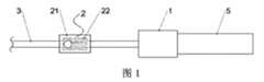
図1は、本発明の一実施例における凍結癒着装置の構造を示す概略図であり、図2は、本発明の一実施例における凍結癒着装置の構造を示す概略図1であり、図3は、本発明の一実施例における凍結癒着装置の構造を示す概略図2である。FIG. 1 is a schematic diagram showing the structure of a cryoadhesion device according to an embodiment of the present invention, FIG. 2 is a schematic diagram 1 showing the structure of a cryoadhesion device according to an embodiment of the present invention, and FIG. Fig. 2 is a schematic diagram 2 showing the structure of a cryoadhesion device in one embodiment of the present invention;
図1~図3を参照し、凍結癒着装置は、遠隔制御組立体2、弁本体組立体1、プローブヘッドカテーテル組立体3およびガスボンベ5を含む。1-3, the cryoadhesion device includes a
前記遠隔制御組立体2は、ジャケット構造21と、前記ジャケット構造21に取り付けられたリモコン22とを含み、前記ジャケット構造21には、前記プローブヘッドカテーテル組立体が通過するためのカテーテル通路が設けられ、前記弁本体組立体1の両端は、前記プローブヘッドカテーテル組立体3と前記ガスボンベ5にそれぞれ接続される。The
前記ジャケット構造21は、前記プローブヘッドカテーテル組立体3を押圧することができ(例えば、操作者の制御によって押圧されてもよく、ジャケット構造21が制御を受けずに押圧されてもよい)、前記プローブヘッドカテーテル組立体3は、押圧が維持される間、前記カテーテル通路の内壁と前記プローブヘッドカテーテル組立体3との間の摩擦力により、前記ジャケット構造21とともに移動することができ、
このように、そこでの押圧は、押圧によって発生する摩擦力によって両者が一緒に移動することが可能な押圧と理解することができ、その押圧を形成する原理や方法は任意であり、例えば、ジャケット構造21の少なくとも一部の構造の変形や、少なくとも一部の構造の移動によって形成することができる。いずれにしても、本実施例の説明から逸脱するものではない。The
Thus, the pressing there can be understood as a pressing that allows both to move together due to the frictional force generated by the pressing, and the principle and method of forming the pressing are arbitrary. It can be formed by structural deformation of at least part of
前記リモコン22は、トリガーされるときに前記弁本体組立体1にトリガー信号を送信するために使用され、
前記弁本体組立体1は、前記トリガー信号を受信するときに、前記プローブヘッドカテーテル組立体3が凍結を実施可能にするように、前記ガスボンベのガスを前記プローブヘッドカテーテル組立体3に供給するために使用される。The
When the valve body assembly 1 receives the trigger signal, the valve body assembly 1 is for supplying the gas of the gas cylinder to the probe
そこでの凍結の実施は、ガスを供給する場合に、ジュール・トムソン効果(Joule-Thomson effect)による絞り込みで冷却量を発生させることで、プローブヘッドカテーテル組立体3におけるプローブヘッドの外部の組織を凍結させて癒着させることと理解できる。When the gas is supplied, the freezing is performed by generating a cooling amount by constriction due to the Joule-Thomson effect, thereby freezing the tissue outside the probe head in the probe
そこでのトリガー信号は、どのような形態や内容の信号であってもよく、弁本体組立体1が該信号を認識して、かつそれに応答してガスを供給することで凍結を実現することができれば、本実施例の説明から逸脱するものではない。例えば、無線手段で送信してもよく、例えば無線の方式で送信してもよいが、有線手段で送信するという解決手段を完全に排除するものではない。いずれにしても、手と足を共同に動かす必要がなく、また、凍結の制御やカテーテルの押し込みおよび引き出しを片手で容易に実現することができる。The trigger signal there may be a signal of any form or content, and the valve body assembly 1 recognizes the signal and supplies gas in response to it to achieve freezing. If possible, no deviation from the description of the present embodiment should be made. For example, it may be transmitted by wireless means, eg in a wireless manner, but does not entirely exclude the solution of transmitting by wire means. In any case, there is no need to move hands and feet together, and freezing control and catheter insertion and withdrawal can be easily achieved with one hand.
このように、本実施例に係る解決手段では、プローブヘッドカテーテル組立体が遠隔制御組立体のカテーテル通路を通過するため、凍結の制御とカテーテルの押し込み/引き出しの両方とも遠隔制御組立体に基づいて実現することができ、さらに操作者が凍結の制御およびカテーテルの押し込み/引き出しを片手で容易に実現することができ、経内腔凍結癒着技術の操作を簡略化し、手術の利便性と安全性を向上させる。また、フットスイッチなどの部材がなく、電磁弁を使用するため、省スペースの効果が図られる。Thus, in the exemplary solution, both freezing control and catheter pushing/withdrawing are based on the remote control assembly because the probe head catheter assembly passes through the catheter passageway of the remote control assembly. Furthermore, the operator can easily achieve freezing control and catheter push/pull-out with one hand, simplifying the operation of the transluminal cryoadhesion technique and increasing the convenience and safety of surgery. Improve. In addition, since there is no member such as a foot switch and an electromagnetic valve is used, the effect of space saving can be achieved.
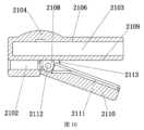
図4は、本発明の一実施例における弁本体組立体の構造を示す概略図であり、図5は、本発明の一実施例における電磁弁の概略断面図であり、図6は、本発明の一実施例におけるエジェクターピンの構造を示す概略図である。FIG. 4 is a schematic diagram showing the structure of a valve body assembly according to one embodiment of the present invention, FIG. 5 is a schematic cross-sectional diagram of an electromagnetic valve according to one embodiment of the present invention, and FIG. 1 is a schematic diagram showing the structure of an ejector pin in one embodiment of FIG.
図4~図6を参照し、前記弁本体組立体1は、電磁弁11と受信回路基板12とを含む。4 to 6, the valve body assembly 1 includes an electromagnetic valve 11 and a receiving
前記電磁弁11は、エジェクターピン111、エジェクターピンチューブ113、エジェクターピンリセット部材114、基台112およびエジェクターピン駆動構造を含み、前記エジェクターピン111内には吸気通路1111が設けられ、前記エジェクターピン111は、前記エジェクターピンチューブ113に穿設され、前記エジェクターピンチューブ113の一端は、前記プローブヘッドカテーテル組立体3に接続されるために使用され、他端は前記基台112の一側に接続され、前記基台112の他側は、前記ガスボンベ5に接続されるために使用され、前記エジェクターピン111の一端は、前記プローブヘッドカテーテル組立体3内に接続される。The electromagnetic valve 11 includes an
前記エジェクターピン駆動構造は、前記受信回路基板12が前記トリガー信号を受信するときに、前記エジェクターピン111を吸気位置に駆動するために使用される。The ejector pin driving structure is used to drive the
そこでの駆動とは具体的には、トリガー信号が受信されるときに、エジェクターピン駆動構造が、エジェクターピン111が吸気位置にある場合に、それが吸気位置に維持するように駆動でき、エジェクターピン111が吸気位置にない場合に、それが吸気位置に移動するように駆動できることを指すことができる。また、エジェクターピン駆動構造は、受信回路基板12の制御下で上記駆動を実施してもよい。Specifically, when the trigger signal is received, the ejector pin drive structure can be driven to maintain the
そこでの吸気位置は、前記吸気位置にあるエジェクターピン111が、前記ガスボンベ5内のガスが前記吸気通路1111に入り、かつ前記吸気通路を通じて前記プローブヘッドカテーテル組立体に供給されるように、前記ガスボンベ5に挿入可能であると理解できる。 The inspiratory position there is such that the
前記エジェクターピンリセット部材は、前記エジェクターピン111が前記エジェクターピン駆動構造によって駆動されていないときに、前記エジェクターピン111を前記吸気位置から非吸気位置にリセットするように駆動するために使用され、前記非吸気位置にあるエジェクターピンが前記ガスボンベに挿入されていない。The ejector pin reset member is used to drive the
さらに、ガスボンベ5には、ガスボンベ出口をシールするためのシール構造(例えば、後部シール構造512)が設けられてもよく、そのシール構造は、エジェクターピン111が入るときに、ガスボンベ出口をシールしないようにしてもよく、さらに、エジェクターピン111をガスボンベ5に挿入して、そこでのガスを取得して送出することができ、エジェクターピン111がリセットされると、該シール構造はさらに、対応するリセット部材の駆動でガスボンベ出口を再びシールすることができる。In addition, the
上記の非吸気位置は、エジェクターピン111がガスボンベに挿入されない、またはシールを突き当てることができない任意の位置を指すと理解できる。The above non-inspiratory position can be understood to refer to any position in which the
電磁弁11および/または受信回路基板12は、電池パック4によって給電されてもよく、電池パック4は、充電式の電池パックであってもよく、さらに取り外して単独充電することができ、また、電池パック4は、非充電式の電池パックであってもよい。The solenoid valve 11 and/or the receiving
図5に示す実施形態では、エジェクターピン111によって発生する運動は直線運動であり、エジェクターピン111は、エジェクターピンチューブ113の軸方向に沿って移動することができるが、他の任意の実施形態では、エジェクターピン111によって発生する運動は、円弧運動や曲線運動などでもよい。In the embodiment shown in FIG. 5, the motion generated by the
図示の実施形態では電磁弁11が採用されるため、エジェクターピン駆動構造は、通電時に所望の電磁力を発生させる電磁コイル116を含み得、さらに、エジェクターピン111は、該電磁力の駆動下で運動(例えば、図5に示す左から右への運動)することができる。該電磁コイル116は、対応する電磁弁ハウジング117に装着可能であり、該電磁弁ハウジング117は、基台112、エジェクターピンチューブ113に対して位置が固定されてもよい。例えば、固定ナット118をエジェクターピンチューブ113の前部外側のネジ部にねじ込むことで、電磁弁ハウジング117と基台112を互いに固定することができる。Since the illustrated embodiment employs an electromagnetic valve 11, the ejector pin drive structure may include an
他の任意の実施形態では、電磁弁11以外の他の原理を用いた弁設備は、除外されない。In any other embodiment, valve equipment using other principles than the solenoid valve 11 is not excluded.
そこでのエジェクターピンリセット部材は、外力によって変形する(例えば曲げ、引き上げ、圧縮し、折り曲げるなど)ことができ、かつ外力が除去されるときにリセット力を発生させる任意の部材であると理解でき、一例では、エジェクターピンリセット部材はバネであってもよい。該バネは、エジェクターピンが吸気位置に入ると伸びたり縮んだりすることができ、さらに、エジェクターピンを吸気位置に駆動する力(例えば、電磁力)がなくなると、エジェクターピンリセット部材は、それが吸気位置から離れて非吸気位置に入るように駆動することができる。An ejector pin reset member therein can be understood to be any member that can be deformed (e.g., bent, lifted, compressed, bent, etc.) by an external force and that generates a reset force when the external force is removed; In one example, the ejector pin reset member may be a spring. The spring can expand and contract when the ejector pin is in the intake position, and when the force (e.g., electromagnetic force) driving the ejector pin to the intake position is removed, the ejector pin reset member causes it to It can be driven away from the inspiratory position and into the non-inspiratory position.
一実施形態では、図5および図6を参照し、前記エジェクターピン111は、順に接続された第1のピン部1115、第2のピン部1116、第3のピン部1117および第4のピン部1118を含み、それらは、図6に示すように、直径の異なる4つの部分であってもよい。In one embodiment, referring to FIGS. 5 and 6, the
前記第1のピン部1115は、前記プローブヘッドカテーテル組立体3の吸気キャビティ372に挿入され、また、第1のピン部1115と吸気キャビティ372との間で動的なシールを実現することができ、一例では、第1のピン部1115の外側にシールリング119が設けられてもよく、該シールリング119は、第1のピン部1115の外側の環状のシールリング溝1114内に設けられてもよい。The
前記第4のピン部1118は、前記ガスボンベ5に挿入されるために使用され、ここで、前記第4のピン部1118の側壁には、吸気孔1112が設けられ得、前記エジェクターピン111が前記ガスボンベ5に挿入されるときに、ガスは、前記吸気孔1112から前記吸気通路1111に入ることが可能である。該吸気孔1112の数量、寸法、配置方法は任意であり、図6に示すものに限定されない。The
前記第3のピン部1117の外径は、前記エジェクターピンチューブ113の内径と一致し、さらに、第3のピン部1117によって、エジェクターピン111は、エジェクターピンチューブ113の内壁に沿って移動し,ガイド作用を果たすことができる。The outer diameter of the
前記第2のピン部1116の外径は、前記第3のピン部1117の外径よりも小さく、前記エジェクターピンリセット部材114は、第2のピン部1116の外側に設けられる。このように、第2のピン部1116によって、エジェクターピンリセット部材114の移動のための空間を提供することができる。The outer diameter of the
これらのピン部の寸法関係(例えば、長さの大きさ、外径の大きさなど)は、図6に示すようなものであってもよいし、その他の寸法関係や形状であってもよいが、上記の要件を満たすものであれば、いずれも本実施例の説明から逸脱するものではない。The dimensional relationship (for example, length, outer diameter, etc.) of these pin portions may be as shown in FIG. 6, or may be other dimensional relationships and shapes. However, as long as it satisfies the above requirements, it does not deviate from the description of this embodiment.
図5を参照し、一実施形態では、前記エジェクターピンチューブ113の内側には、エジェクターピン制限部1131が固定的に設けられ、前記エジェクターピンリセット部材114は、前記エジェクターピン制限部1131に接続され、例えば、エジェクターピンリセット部材114がバネである場合、バネの一端は、当該エジェクターピン制限部1131に接続され得る。Referring to FIG. 5 , in one embodiment, an ejector
前記エジェクターピン制限部1131は、前記第3のピン部1117の前記ガスボンベ5から離れた一端を止めることが可能であり、前記エジェクターピンリセット部材1131は、リセット時に前記エジェクターピンの移動位置を制限するように、前記第2のピン部の外側に配置される。The ejector
具体的には、図5を例として挙げると、電磁力を受けてエジェクターピン1が図示の右に移動して吸気位置に入り、このときに、バネが圧縮され得、電磁力がなくなると、バネは、エジェクターピンに作用する左向きの力を発生させて左に移動させ、限界位置に移動するときに、第3のピン部1117の前端は、エジェクターピン制限部1131に当接してエジェクターピン制限部1131によって制限され得る。Specifically, taking FIG. 5 as an example, the ejector pin 1 receives the electromagnetic force and moves to the right in the drawing to enter the intake position. The spring generates a leftward force that acts on the ejector pin to move it to the left, and when it moves to the limit position, the front end of the
具体的な実施プロセスでは、前記エジェクターピン制限部1131は、少なくとも2つの扇形制限部を含み、前記少なくとも2つの扇形制限部は、隣接する2つの扇形制限部の間に圧力開放ギャップを形成するように、前記エジェクターピンの円周方向に沿って間隔を置いて配置される。In a specific implementation process, said
図6を参照し、具体的な実施プロセスでは、前記第3のピン部1117には、前記第3のピン部1117の両端を貫通する圧力開放溝1113が設けられる。Referring to FIG. 6 , in a specific implementation process, the
前記エジェクターピン111が前記ガスボンベ5に挿入されないときに、すなわち、吸気位置にないときに、前記吸気通路1111のガスは、前記吸気孔1112、前記圧力開放溝1113、前記圧力開放ギャップを順に経由して、前記第2のピン部1116と前記エジェクターピンチューブ113の内壁との間の間隔空間に排出され得、迅速排気の通路の一部を形成することができる。When the
上記の電磁弁によって、エジェクターピンに基づいてガスボンベの迅速な開放と吸気の迅速な圧力開放を実現することができ、例えば、リモコンを押下して凍結を実現でき、押下開放して排気できることで、排気と再昇温を実現することができる。With the above solenoid valve, the quick opening of the gas cylinder and the quick pressure release of the suction can be realized based on the ejector pin. Evacuation and reheating can be realized.
図5を参照し、一実施形態では、前記第2のピン部1116の外側には、エジェクターピン雄ねじが設けられ、前記エジェクターピン雄ねじは、制限ナット115に嵌合接続され、前記エジェクターピンリセット部材114は、前記制限ナット115に接続され、このように、エジェクターピンリセット部材114がバネである場合、その伸縮方向はエジェクターピンとエジェクターピンチューブの軸方向であってもよく、かつ該軸方向に沿って制限ナット115とエジェクターピン制限部1131がそれぞれ接続される。Referring to FIG. 5, in one embodiment, the
ここで、前記制限ナット115は、前記エジェクターピン雄ねじに対する回転により、前記エジェクターピンリセット部材114の圧縮量または引張量を変化させるように、前記エジェクターピン111に対する位置を調整することが可能である。Here, the
また、図5に示す例では、電磁力を受けたエジェクターピンの移動により、バネが圧縮される場合があり、他の例では、例えば、制限ナットはバネの左側にあるが、エジェクターピンチューブ113に固定的に接続され、他の固定部は、エジェクターピン111に固定的に接続され、かつバネの右側にあり、このときに、電磁力を受けたエジェクターピンの移動により、バネが引張され得る。いずれにしても、本実施例の説明から逸脱するものではない。Also, in the example shown in FIG. 5, movement of the ejector pin under electromagnetic force may cause the spring to be compressed, and in other examples, for example, the limit nut is to the left of the spring, but the
一実施形態では、図4を参照し、前記弁本体組立体1は、弁本体ハウジング13をさらに含み、前記電磁弁11および前記受信回路基板12は、前記弁本体ハウジング13内に設けられる。In one embodiment, referring to FIG. 4 , the valve body assembly 1 further includes a
一例では、受信回路基板12は、弁本体ハウジング13の貫通孔によって外部に連通され、操作されるのに適した弁本体ボタン121を有してもよい。該弁本体ボタン121は、リモコンが動作できない場合に、該弁本体ボタン121を押して凍結を開始するバックアップボタンとして使用してもよい。In one example, the receiving
弁本体ハウジング13は、2つのハーフハウジング133を含んでもよく、該2つのハーフハウジングは、留め具またはねじによって接続されてもよく、かつ縫い目はシールされてもよい。The
弁本体ハウジング13には、それぞれ前部排気孔と後部排気孔とみなすことができる第1の排気孔131と第2の排気孔132がさらに設けられ得、ガスを後部に排出するようにガイドすることために使用することができ、具体的には、ガスが第1の排気孔131から内部空洞に入った後、第2の排気孔132によってガスボンベフード6に排出されてもよく、例えば、ガスボンベフード6の尾部排出孔61によって排出されてもよく、戻りガスの排気や吸気停止後の迅速な排気に使用されてもよい。The
また、弁本体ハウジング13には、リモコン配置溝がさらに設けられ得、さらに、遠隔制御組立体2またはその内部のリモコン22を弁本体ハウジング13上のリモコン配置溝に配置してもよく、別の解決手段では、遠隔制御組立体2またはその内部のリモコン22を弁本体組立体に吊り下げまたは吸着させ、リモコンの紛失を防止することもできる。Also, the
上記の電磁弁および受信回路基板の電源は、電池パックによって供給されてもよいし、ケーブルをソケットに接続することで供給されてもよく、さらに、ケーブルによって交流電流を直接供給してもよいし、ケーブル内に整流回路を配置することで、交流電流を直流電流に変換して電磁弁および受信回路基板に供給してもよい。The power supply for the solenoid valve and the receiving circuit board may be supplied by a battery pack, may be supplied by connecting a cable to a socket, or may be directly supplied by a cable. Alternatively, a rectifying circuit may be arranged in the cable to convert alternating current to direct current and supply it to the solenoid valve and the receiving circuit board.
図7は、本発明の一実施例におけるジャケット構造およびリモコンの構造を示す概略図1であり、図8は、本発明の一実施例におけるジャケット構造を示す概略断面図1であり、図9は、本発明の一実施例におけるジャケット構造およびリモコンの構造を示す概略図2であり、図10は、本発明の一実施例におけるジャケット構造を示す概略断面図2である。FIG. 7 is a schematic diagram 1 showing the jacket structure and the structure of the remote control in one embodiment of the present invention, FIG. 8 is a schematic sectional view 1 showing the jacket structure in one embodiment of the present invention, and FIG. 10 is a schematic
図7~図10を参照し、前記ジャケット構造21は、リモコンジャケット部2106を含み、前記リモコンジャケット部2106は、トリガー部材(例えば、図示のリモコンボタン214)と、前記リモコン22を収容するためのリモコンキャビティ2103とを有する。前記トリガー部材は、トリガーされるときに、前記リモコンキャビティ2103内のリモコン22のボタンスイッチ2221をトリガーすることができる。7-10, the
上記の解決手段により、ジャケット構造21に対するリモコン22の収容装着を実現することができる。With the above solutions, it is possible to accommodate and mount the
一実施形態では、前記ジャケット構造21は、通路ベース2107をさらに含む。前記カテーテル通路は、前記通路ベース2107に設けられ、前記通路ベース2107は、前記リモコンジャケット部2106に固定的に接続される。具体的には、両者が一体となってもよいし、一体に組み立てられてもよい。In one embodiment, said
図7および図8に示す実施形態では、前記通路ベース2107内のカテーテル通路は、ガイド通路2102と押圧通路2101とを含み、前記押圧通路2101の内径は、前記ガイド通路よりも大きく、また、ガイド通路2102の内径は、プローブヘッドカテーテル組立体3内のカテーテルの外径よりも大きく、
前記押圧通路2101の内壁は、前記通路ベース2107の対応する位置が挟まれるときに変形し、かつ前記プローブヘッドカテーテル組立体3を押圧することが可能である。7 and 8, the catheter passageway within the
The inner wall of the pushing
前記押圧通路2101の内壁は、軟質の粗面を有してもよく、例えば、押圧通路2101の内壁には、ゴム系またはシリコン系の軟質の粗面材料が設けられてもよく、および/または、前記通路ベース2107および前記リモコンジャケット部2106の対応する部分は、ゴム系またはシリコン系の軟質の粗面材料を採用してもよく、軟質の粗面の設計によって、カテーテルとの摩擦力を高めやすくなり、操作制御を実施しやすい。The inner wall of the
前記ガイド通路2102によって、カテーテル32を、折り曲げないように所望の方向にガイドすることができ、具体的には、ガイド通路2102の内壁は、硬質の平滑面を有してもよく、さらに、カテーテル32がその内部で摺動する滑らかさを向上させ、その内部でのプローブヘッドカテーテル組立体3の低抵抗の移動が確保され得る。 The
このように、図7および図8に示す実施形態では、遠隔制御組立体2とプローブヘッドカテーテル組立体3との共同移動は、挟みの方式で実現することができ、該方式で、ジャケット構造21全体を使い捨てにすることができ、一例では、遠隔制御組立体2全体も使い捨てにすることができる。 Thus, in the embodiment shown in FIGS. 7 and 8, joint movement of the
図9および図10に示す実施形態では、前記ジャケット構造21は、押付板2110をさらに含み、前記カテーテル通路は、ガイド通路2102を含み、上記に示すように、該ガイド通路2102も通路ベース2107に設けられる。 In the embodiment shown in FIGS. 9 and 10, the
前記押付板2110は、前記リモコンジャケット部2106に回転可能に接続され、例えば、リモコンジャケット部2106と押付板2110は、雌型回転ジョイント2108および雄型回転ジョイント2112を回転させることによって接続することができ、該ジョイントを中心に押付板2110が一定の角度で回転してもよい。The
前記押付板2110の前記リモコンジャケット部2106に対向する一側には、押圧溝2111が設けられ、前記リモコンジャケット部2106の外面には押圧面2109が設けられ、前記プローブヘッドカテーテル組立体3(例えば、そのカテーテル)は、前記押圧溝2111と前記押圧面2109との間を通過し、かつ前記ガイド通路2102を通過することが可能である。A
前記押付板2110は、押し下げられて回転するときに、前記押圧溝2111および前記押圧面2109で前記プローブヘッドカテーテル組立体を押圧するために使用される。The
前記押圧面2109および/または前記押圧溝2111の内壁は、軟質の粗面を有し、例えば、ゴム系またはシリコン系の軟質の粗面材料を使用することができる。 The
また、図7および図8に示す実施形態と同様に、本実施形態におけるガイド通路2102の内壁は、上記に示すような硬質の平滑面を有してもよい。 Also, similar to the embodiment shown in FIGS. 7 and 8, the inner wall of the
図9および図10を参照し、前記ジャケット構造1は、押付板リセット部材2113をさらに含み、前記押付板リセット部材2113は、前記押付板2110と前記リモコンジャケット部2106との間に接続され、前記押付板2110が押し下げられないときに、前記プローブヘッドカテーテル組立体が押圧されないように、前記押付板2110を回転させてリセットするように駆動するために使用される。 9 and 10, the jacket structure 1 further includes a pressing
一例では、押付板リセット部材2113は、例えば、弾性シートであってもよく、弾性シートは、押付板2110が設けられた弾性シートスロット(図示せず)および下部弾性シートスロット2105に配置されてもよい。In one example, the pressure
上記の解決手段では、プローブヘッドカテーテル組立体3をガイド通路2102内に通し、押付板2110を指で押すことにより、押付板リセット部材2113を圧縮することができ、プローブヘッドカテーテル組立体3は、押圧溝2111と押圧面2109との間に押し込まれて移動できなくなり、このときに、プローブヘッドカテーテル組立体3の押し込みと引き出しを実現でき、押付板2110を開放すると、押付板2110は、押付板リセット部材2113の弾性力により回転してリセットする(すなわち、ひっくり返す)ことができ、プローブヘッドカテーテル組立体3(例えば、そのカテーテル32)は、自由に移動できる状態に戻る。In the above solution, the probe
図9および図10に示す解決手段では、プローブヘッドカテーテル組立体3は、自然状態では自由に移動可能であり、押付板を押すと、プローブヘッドカテーテル組立体3が押圧されて固定され、他の任意の解決手段では、自然状態でプローブヘッドカテーテル組立体3が押圧されて固定され、押付板を押すとカテーテルが自由に移動可能であるように構成することもできる。 In the solution shown in FIGS. 9 and 10, the probe
このように、他の実施形態では、前記押付板2110は、前記押付板2110が押し下げられないときに、前記押圧溝2111および前記押圧面2109が前記プローブヘッドカテーテル組立体3を押圧し、前記押付板が押し下げられるときに、前記押圧溝および前記押圧面が前記プローブヘッドカテーテル組立体を押圧しないように使用される。これに対応して、押付板リセット部材2113は、前記プローブヘッドカテーテル組立体3が押圧されるように、前記押付板2110が押し下げられないときに前記押付板2110を回転させてリセットするように駆動するために使用される。Thus, in another embodiment, the
具体的な実施プロセスでは、いずれにして押圧を実現しても、ジャケット構造全体、前記リモコンおよび前記プローブヘッドカテーテル組立体のうちの少なくとも1つは、使い捨てにしてもよい。In a specific implementation process, no matter how the pressing is achieved, at least one of the entire jacket structure, said remote control and said probe head catheter assembly may be disposable.
図11は、本発明の一実施例におけるリモコンの概略断面図である。FIG. 11 is a schematic cross-sectional view of a remote controller in one embodiment of the invention.
図11を参照し、リモコン22は、発射回路基板222、ボタン電池223およびリモコンハウジング221を含んでよく、発射回路基板222およびボタン電池223は、リモコンハウジング221内に配置され、リモコンハウジング221は、電池カバー224が装着可能であり、ボタン電池223は、電池カバー224の対応する位置に装着可能であり、ボタン電池223の交換に使用されてもよい。11, the
発射回路基板222には、上記のボタンスイッチ2221が配置されてもよく、リモコン22の発射回路基板を開閉するための保護スイッチ2222がされに配置されてもよく、それにより、発射回路基板222のボタンスイッチ2221は、トリガーされても対応して作用せず、ボタンスイッチ2221は、リモコンボタン2104が押し下げられるときにトリガーされ、さらに、トリガーされた後に、発射回路基板がトリガー信号を発することができるために使用される。該解決手段では、保護スイッチ2222をオフにすることで、リモコンボタン2104への不用意なタッチを防止することができる(すなわち、ボタンスイッチ2221が誤ってトリガーされることを防止する)。The above-mentioned
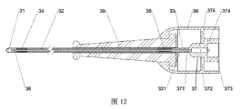
図12は、本発明の一実施例におけるプローブヘッドカテーテル組立体の概略断面図である。Figure 12 is a schematic cross-sectional view of a probe head catheter assembly in one embodiment of the invention.
図12を参照し、前記プローブヘッドカテーテル組立体3は、順に接続されたプローブヘッド31、カテーテル32および継手構造37を含み、前記カテーテルには、吸気管36が設けられ、前記継手構造37は、前記弁本体組立体1に接続され、前記継手構造37は、前記弁本体組立体1(例えば、その吸気通路1111)からのガスを前記吸気管36に供給し、かつ前記吸気管36を通じて前記プローブヘッド31に供給することが可能であり、前記カテーテル32は、前記カテーテル通路に穿設される。Referring to FIG. 12, the probe
一実施形態では、前記継手構造37は、継手本体375、接続部373およびヘッドチューブ371を含んでもよく、前記継手本体375には、吸気キャビティ372が設けられ、前記接続部373と前記ヘッドチューブ371はそれぞれ、前記継手本体375の両端に設けられる。In one embodiment, the
前記吸気キャビティ372は、前記弁本体組立体のエジェクターピンが前記接続部を通過して插入されるために使用され、また、動的なシールを実現することができる。前記吸気管36は、前記ヘッドチューブ371を通過して前記吸気キャビティ372に接続される。具体的には、吸気管36は、カテーテル32全体の内部に配置され、かつその前端がプローブヘッド31の前段の内部にあり、その後端がヘッドチューブ371に挿入されて固定的にシールされる。The
前記接続部373は、前記弁本体組立体内のエジェクターピンチューブ113にドッキングするために使用され、例えば、接続部373は、プローブヘッドカテーテル部材3と弁本体部材1との接続を実現するように、エジェクターピンチューブ113の前端のネジ部と相互に接続される雌ネジ部を含む。The
一実施形態では、上記の圧力開放溝1113、第1の排気孔131および第2の排気孔132などと連携して迅速な排気を実現するために、前記接続部には、圧力開放孔374が設けられ、前記圧力開放孔374の一端は、前記エジェクターピン111と前記エジェクターピンチューブ113の内壁との間の間隔空間に連通され、他端は、弁本体組立体1内の第1の排気孔131に直接または間接的に連通され、
前記エジェクターピンが前記ガスボンベに挿入されないときに、すなわち、エジェクターピンが吸気位置にないときに、前記エジェクターピン111と前記エジェクターピンチューブ113の内壁との間の間隔空間に排出されたガスは、前記圧力開放孔374、前記第1の排気孔131、前記弁本体ハウジング13の内部キャビティを順に経由して、前記第2の排気孔132に排出され得、さらに、第2の排気孔132を経由してガスボンベフード6の尾部排出孔61に排出されてもよく、ガスボンベ5は、ガスボンベフード6内に設けられ得る。In one embodiment, the connection includes a
When the ejector pin is not inserted into the gas cylinder, that is, when the ejector pin is not in the intake position, the gas discharged into the space between the
一実施形態では、プローブヘッド内のガスの戻りを実現するために、前記プローブヘッドカテーテル組立体3は、リターンチューブ33および継手ハウジング38をさらに含み、前記継手構造37は、前記継手ハウジング38内に設けられてもよく、前記継手ハウジング38には、継手排気孔(図示せず)が設けられ、継手排気孔は、具体的に、継手ハウジング38の内部固定板(図示せず)にあることができ、前記リターンチューブ33は、前記カテーテル32と前記継手構造37との間に接続され、前記リターンチューブ33は、前記吸気管の外側にループ状に配置され、かつ前記カテーテル32と前記吸気管36との間の間隔空間を連通し、前記リターンチューブ33の管壁には、リターン孔331が設けられる。In one embodiment, the probe
ここで、前記カテーテル32と前記吸気管36との間の間隔空間に戻ったガスは、前記リターンチューブ33、前記リターン孔331、前記継手ハウジング38の内部キャビティ、前記継手排気孔、前記第1の排気孔131、前記弁本体ハウジング13の内部キャビティを順に経由して、前記第2の排気孔132に排出され得、さらに、第2の排気孔132を経由してガスボンベフード6の尾部排出孔61に排出され得、ガスボンベ5は、ガスボンベフード6内に設けられ得る。Here, the gas that has returned to the space between the
一例では、前記プローブヘッドカテーテル組立体3は、前部押圧管34および後部押圧管35をさらに含んでもよく、前部押圧管34は、カテーテル32に嵌設され、かつカテーテル32を押圧することによってプローブヘッド31とカテーテル32との接続およびシールを実現し、後部押圧管35は、カテーテル32に嵌設され、かつカテーテル32を押圧することによってリターンチューブ33とカテーテル32の接続およびシールを実現し、リターンチューブ33の後端は、ヘッドチューブ371に嵌設されて固定的にシールされる。In one example, the probe
一例では、前記プローブヘッドカテーテル組立体3は、カテーテル32および後部押圧管35の外側に嵌設されたベンドガード39をさらに含んでもよく、継手ハウジング38は、ベンドガードホース39および継手構造37の位置を固定してもよい。In one example, the probe
また、上記のプローブヘッドカテーテル部材3は、使い捨て部材であってもよく、さらに、クロスコンタミネーションを回避する効果がある。Moreover, the probe
一実施形態では、ガスボンベ5は、寸法の小さいミニガスボンベを採用することができ、その結果、占用スペースを減少し、さらに操作プロセスを簡略化することにも有利である。このように、電磁弁をミニガスボンベと接続して一体構造を形成し、その後、電磁弁とミニガスボンベの一体構造、あるいは電磁弁と、ミニガスボンベと電池パックの一体構造により、内腔凍結癒着技術をホストと大型ガスボンベから完全に解放することができる。In one embodiment, the
具体的な実施プロセスでは、ガスボンベ内のガスは、二酸化炭素または亜酸化窒素を採用することができる。In a specific implementation process, the gas in the gas cylinder can adopt carbon dioxide or nitrous oxide.
図13は、本発明の一実施例における凍結癒着装置の概略断面図であり、図14は、本発明の一実施例における凍結癒着装置の使用状態を示す概略図である。FIG. 13 is a schematic cross-sectional view of a cryo-adhesion device according to one embodiment of the present invention, and FIG. 14 is a schematic view showing the state of use of the cryo-adhesion device according to one embodiment of the present invention.
図13および図14を参照し、具体的な応用解決手段を以下に説明し、以下および上記の前後(例えば、前端、後端、前方に移動、後方に移動など)とは、プローブヘッドに近い方向が前で、ガスボンベに近い方向が後であると理解できる。13 and 14, specific application solutions are described below, and the following and above front and rear (for example, front end, rear end, forward movement, rearward movement, etc.) are close to the probe head It can be understood that the direction is the front and the direction closer to the gas cylinder is the rear.
具体的な応用解決手段では、リモコンボタン2104を押下げると、電磁弁11が開き、エジェクターピン111が電磁力で後方に移動し、バネ114が圧縮され、エジェクターピン111の後段がガスボンベ出口51の内部に挿入され、エジェクターピン111の後段がガスボンベ5の前部シール機構511と軸方向の動的シールを実現して後部シール機構512を突き当て、ガスボンベ5内のガスは、吸気孔1112、吸気通路1111、吸気キャビティ372および吸気管36を順に経由してプローブヘッド31の内部に到達し、ジュール・トムソン効果による絞り込みで冷却量を発生させ、プローブヘッドの外部の組織を凍結させて癒着させ、戻りガスは、カテーテル32(具体的には、カテーテル32と吸気管36の間隔空間)、リターンチューブ33、リターン孔331、継手排気孔、第1の排気孔131、弁本体ハウジング13の内部キャビティ、後部排気孔132および尾部排出孔61を順に経由して排出される。In a specific application solution, when the
凍結癒着が完了した後、リモコンボタン2104を開放すると、電磁弁11が閉じられ、電磁力がなくなり、エジェクターピン111は、バネなどのエジェクターピンリセット部材114の作用で前方に移動し、エジェクターピン111の後段(例えば、第4のピン部1118)は、ガスボンベ出口51から離れ、後部シール機構512がガスボンベ出口を瞬間的にシールし、また、吸気管36および吸気通路1111内の過剰なガスは、吸気孔1112から排出され、それによって、迅速な排気が達成されることにより、プローブヘッド31が室温に迅速に戻り、癒着組織との分離を実現することができる。吸気孔1112から排出されたガスは、圧力開放溝1113、エジェクターピン制限部1131の圧力開放ギャップ、エジェクターピンリセット部材が位置する間隔空間(すなわち、第2のピン部1116とエジェクターピンチューブ113との間の間隔空間)、圧力開放孔374、第1の排気孔131、第2の排気孔132および尾部排出孔61を順に経由して排出される。When the
実際の応用では、プローブヘッドカテーテル部材3とジャケット構造21の一部または全部を使い捨てにすることができ、ガスボンベ5は、圧力が足りなくなるときに交換する必要があり、電池パック4は、電池残量が足りなくなるときに予備電池パックと交換することができ、電池パックを取り外して単独充電することができ、一例では、残りの部材は、いずれも再利用することができる。In practical applications, part or all of the probe
また、戻りガスまたは排気が尾部排出孔61以外の位置から排出されることを防止するように、全ての左右のハウジング間、各部材のハウジング間には、シール機構が設けられる。In addition, a sealing mechanism is provided between all the left and right housings and between the housings of each member so as to prevent return gas or exhaust from being discharged from positions other than the
手術操作中に、内視鏡が病変部付近に到達した後、プローブヘッド31を遠隔制御組立体2に挿入し、かつ遠隔制御組立体2の後端の両側を親指と人差し指で挟み、押圧通路2101を親指と人差し指で押圧し、摩擦力によりカテーテル32と遠隔制御組立体2を固定し、次にプローブヘッド31を前方に押圧し、内視鏡のクランプ通路からプローブヘッド31を插入し、親指と人差し指を離して、押圧通路2101を元の形状に戻し、遠隔制御組立体2をカテーテル32に沿って後方に移動させ、親指と人差し指でカテーテル32を再び前方に押圧し、プローブヘッド31が病変部に接触するまで繰り返し、この際、押圧通路2101の押圧状態を維持し、かつ同じ手の中指でリモコンボタン2104を押し下げることで凍結を開始し、プローブヘッドが組織に癒着した後、凍結状態を維持し続け(リモコンボタン2104を押し下げ)、病変部組織を気管鏡のクランプ通路から引き出すか、または内視鏡とともに引き出す。病変部組織を引き出した後、中指を離して凍結を停止させ、サンプリングを完了する。During surgical operation, after the endoscope reaches the vicinity of the lesion, the
以上より、本実施例が提供する凍結癒着装置では、プローブヘッドカテーテル組立体が遠隔制御組立体のカテーテル通路を通過するため、凍結の制御とカテーテルの押し込み/引き出しの両方とも遠隔制御組立体に基づいて実現することができ、さらに操作者が凍結の制御およびカテーテルの押し込み/引き出しを片手で容易に実現することができ、フットペダルやホストなどを使用せず、経内腔凍結癒着技術の操作を簡略化し、手術の利便性と安全性を向上させる。また、フットスイッチなどの部材がなく、電磁弁を使用するため、省スペースの効果が図られる。Thus, in the cryoadhesion device provided by this embodiment, both cryocontrol and catheter push/withdrawal are based on the remote control assembly because the probe head catheter assembly passes through the catheter passageway of the remote control assembly. In addition, the operator can easily control freezing and insert/withdraw the catheter with one hand, and operate the transluminal cryoadhesion technique without using a foot pedal or host. Simplify and improve the convenience and safety of surgery. In addition, since there is no member such as a foot switch and an electromagnetic valve is used, the effect of space saving can be achieved.
最後に、上述した各実施例が本発明の技術的解決手段を説明するためのものに過ぎず、それを限定するものではないと説明すべきであり、前記各実施例を参照しながら本発明を詳細に説明したが、当業者であれば、依然として前記各実施例に記載された技術的解決手段を変更するか、またはそれらの技術的特徴の一部または全部を等価的に置き換えることができること理解すべきであり、これらの変更や置き換えは、対応する技術的解決手段の本質に本発明の各実施例の技術的解決手段の範囲から逸脱させない。Finally, it should be explained that the above-mentioned embodiments are only for describing the technical solutions of the present invention and not for limiting it. has been described in detail, but those skilled in the art can still modify the technical solutions described in the above embodiments, or equivalently replace some or all of their technical features. It should be understood that these modifications and replacements do not make the essence of the corresponding technical solution depart from the scope of the technical solution of each embodiment of the present invention.
1-弁本体組立体;
11-電磁弁;
111-エジェクターピン;
1111-吸気通路;
1112-吸気孔;
1113-圧力開放溝;
1114-シールリング溝;
1115-第1のピン部;
1116-第2のピン部;
1117-第3のピン部;
1118-第4のピン部;
112-基台;
113-エジェクターピンチューブ;
1131-エジェクターピン制限部;
114-エジェクターピンリセット部材;
115-制限ナット;
116-電磁コイル;
117-電磁弁ハウジング;
118-固定ナット;
119-シールリング;
12-受信回路基板;
121-弁本体ボタン;
13-弁本体ハウジング;
131-第1の排気孔;
132-第2の排気孔;
133-ハーフハウジング;
2-遠隔制御組立体;
21-ジャケット構造;
2101-押圧通路;
2102-ガイド通路;
2103-リモコンキャビティ;
2104-リモコンボタン;
2105-下部弾性シートスロット;
2106-リモコンジャケット部;
2107-通路ベース;
2108-雌型回転ジョイント;
2109-押圧面;
2110-押付板;
2111-押圧溝;
2112-雄型回転ジョイント;
2113-押付板リセット部材;
22-リモコン;
221-リモコンハウジング;
222-発射回路基板;
2221-ボタンスイッチ;
2222-保護スイッチ;
223-ボタン電池;
224-電池カバー;
3-プローブヘッドカテーテル組立体;
31-プローブヘッド;
32-カテーテル;
33-リターンチューブ;
331-リターン孔;
34-前部押圧管;
35-後部押圧管;
36-吸気管;
37-継手構造;
371-ヘッドチューブ;
372-吸気キャビティ;
373-接続部;
374-圧力開放孔;
375-継手本体;
38-継手ハウジング;
39-ベンドガード;
4-電池パック;
5-ガスボンベ;
51-ガスボンベ出口;
511-前部シール構造;
512-後部シール構造;
6-ガスボンベフード;
61-尾部排出孔。
1 - valve body assembly;
11 - solenoid valve;
111 - ejector pin;
1111—intake passageway;
1112 - air intake;
1113 - pressure relief groove;
1114 - seal ring groove;
1115—first pin portion;
1116—second pin portion;
1117—third pin portion;
1118—fourth pin portion;
112 - base;
113—ejector pin tube;
1131—ejector pin restriction;
114—ejector pin reset member;
115—limiting nut;
116 - electromagnetic coil;
117—solenoid valve housing;
118—fixing nut;
119 - sealing ring;
12—Receive circuit board;
121 - valve body button;
13 - valve body housing;
131 - first vent;
132—second vent;
133 - half housing;
2 - remote control assembly;
21 - jacket structure;
2101 - pressure passageway;
2102 - guide passageway;
2103 - remote control cavity;
2104 - remote control buttons;
2105—Lower elastic seat slot;
2106 - remote control jacket part;
2107 - walkway base;
2108—female revolute joint;
2109 - pressing surface;
2110 - pressing plate;
2111 - pressing groove;
2112—male revolute joint;
2113—press plate reset member;
22 - remote control;
221 - remote control housing;
222—Launch circuit board;
2221 - button switch;
2222 - protection switch;
223 - button battery;
224—battery cover;
3 - probe head catheter assembly;
31 - probe head;
32 - catheter;
33—return tube;
331 - return hole;
34 - front push tube;
35—posterior pressure tube;
36 - intake pipe;
37—joint structure;
371 - head tube;
372—intake cavity;
373 - connection;
374—Pressure relief hole;
375—fitting body;
38 - joint housing;
39 - bend guard;
4 - battery pack;
5 - gas cylinder;
51 - gas cylinder outlet;
511 - front seal structure;
512—rear seal structure;
6 - gas cylinder hood;
61—tail discharge hole;
Claims (17)
Translated fromJapanese前記ジャケット構造は、前記プローブヘッドカテーテル組立体を押圧することができ、かつ前記プローブヘッドカテーテル組立体は、押圧が維持される間、前記カテーテル通路の内壁と前記プローブヘッドカテーテル組立体との間の摩擦力により、前記ジャケット構造とともに移動することができ、前記遠隔制御組立体は、前記ジャケット構造が前記プローブヘッドカテーテル組立体を押圧しないとき、前記プローブヘッドカテーテル組立体に沿って移動することができ、
前記リモコンは、トリガーされるときに前記弁本体組立体にトリガー信号を送信するために使用され、
前記弁本体組立体は、前記トリガー信号を受信するときに、前記プローブヘッドカテーテル組立体の凍結を可能にするように、前記ガスボンベからのガスを前記プローブヘッドカテーテル組立体に供給するために使用され、
前記ジャケット構造は、リモコンジャケット部を含み、前記リモコンジャケット部は、トリガー部材と、前記リモコンを収容するためのリモコンキャビティとを有し、
前記トリガー部材は、トリガーされるときに、前記リモコンキャビティ内のリモコンのボタンスイッチをトリガーすることができ、それによって、ボタンスイッチがトリガーされるときに前記リモコンが前記トリガー信号を発するようにすることを特徴とする、凍結癒着装置。A remote control assembly, a valve body assembly, a probe head catheter assembly and a gas cylinder, wherein the remote control assembly includes a jacket structure and a remote control attached to the jacket structure, the jacket structure including the a catheter passageway for a probe head catheter assembly to pass through, wherein both ends of the valve body assembly are respectively connected to the probe head catheter assembly and the gas cylinder;
The jacket structure is capable of compressing the probe head catheter assembly, and the probe head catheter assembly maintains pressure between the inner wall of the catheter passageway and the probe head catheter assembly while the compression is maintained. Friction forces may move with the jacket structure, andthe remote control assembly may move along the probe head catheter assembly when the jacket structure does not press against the probe head catheter assembly. ,
the remote control is used to send a trigger signal to the valve body assembly when triggered;
The valve body assembly is used to supply gas from the gas cylinder to the probe head catheter assembly to enable freezing of the probe head catheter assembly when the trigger signal is received. ,
the jacket structure includes a remote control jacket part, the remote control jacket part having a trigger member and a remote control cavity for receiving the remote control;
The trigger member is capable of triggering a button switch of a remote control in the remote control cavity when triggered, whereby the remote control emits the trigger signal when the button switch is triggered. A cryoadhesion device characterized by:
前記押圧通路の内壁は、前記通路ベースの対応する位置が挟まれるときに変形し、かつ前記プローブヘッドカテーテル組立体を押圧することが可能であることを特徴とする、請求項2に記載の凍結癒着装置。the catheter passageway in the passageway base includes a guide passageway and a pushing passageway, the inner diameter of the pushing passageway being larger than that of the guiding passageway, and the inner wall thereof having a soft rough surface;
3. The freeze of claim 2, wherein an inner wall of the push channel is capable of deforming and pushing against the probe head catheter assembly when corresponding locations of the channel base are pinched. adhesion device.
前記押付板は、押し下げられて回転するときに、前記押圧溝および前記押圧面で前記プローブヘッドカテーテル組立体を押圧するために使用され、または、
前記押付板は、前記押付板が押し下げられないときに、前記押圧溝および前記押圧面が前記プローブヘッドカテーテル組立体を押圧し、前記押付板が押し下げられるときに、前記押圧溝および前記押圧面が前記プローブヘッドカテーテル組立体を押圧しなくなるように使用されることを特徴とする、請求項2に記載の凍結癒着装置。The jacket structure further includes a pressing plate, the catheter passageway includes a guide passageway, the pressing plate is rotatably connected to the remote control jacket part, and the pressure plate is on the opposite side of the remote control jacket part. is provided with a pressing groove, a pressing surface is provided on the outer surface of the remote control jacket portion, and the probe head catheter assembly passes between the pressing groove and the pressing surface, and at the same time passes through the guide passage. the pressing surface and/or the inner wall of the pressing groove has a soft rough surface,
the pressing plate is used to press the probe head catheter assembly with the pressing groove and the pressing surface when it is depressed and rotated; or
When the pressing plate is not pressed down, the pressing groove and the pressing surface press the probe head catheter assembly, and when the pressing plate is pressed down, the pressing groove and the pressing surface are pressed. 3. The cryoadhesion device of claim 2, wherein the cryoadhesion device is used to decompress the probe head catheter assembly.
前記エジェクターピン駆動構造は、前記受信回路基板が前記トリガー信号を受信するときに、前記エジェクターピンを吸気位置に駆動するために使用され、前記吸気位置にあるエジェクターピンは、前記ガスボンベ内のガスが前記吸気通路に入り、かつ前記吸気通路を通じて前記プローブヘッドカテーテル組立体に供給されるように、前記ガスボンベに挿入可能であり、
前記エジェクターピンリセット部材は、前記エジェクターピンが前記エジェクターピン駆動構造によって駆動されないときに、前記エジェクターピンを前記吸気位置から非吸気位置にリセットするように駆動するために使用され、前記非吸気位置にあるエジェクターピンが前記ガスボンベに挿入されないことを特徴とする、請求項1-5のいずれか一項に記載の凍結癒着装置。The valve body assembly includes an electromagnetic valve and a receiving circuit board, the electromagnetic valve includes an ejector pin, an ejector pin tube, an ejector pin reset member, a base and an ejector pin drive structure, and within the ejector pin is: An intake passage is provided, the ejector pin is drilled through the ejector pin tube, one end of the ejector pin tube is connected to the probe head catheter assembly, and the other end is connected to one side of the base. the other side of the base is connected to the gas cylinder, one end of the ejector pin is connected into the probe head catheter assembly,
The ejector pin driving structure is used to drive the ejector pin to an intake position when the receiving circuit board receives the trigger signal, and the ejector pin at the intake position is driven by gas in the gas cylinder. is insertable into the gas cylinder so as to enter the inspiratory passageway and be supplied through the inspiratory passageway to the probe head catheter assembly;
The ejector pin reset member is used to drive the ejector pin to reset from the intake position to the non-intake position when the ejector pin is not driven by the ejector pin drive structure. A cryoadhesion device according to any one of claims 1-5, characterized in that an ejector pin is not inserted into the gas bottle.
前記第3のピン部には、その両端を貫通する圧力開放溝が設けられ、
前記エジェクターピンが前記ガスボンベに挿入されていないときに、前記吸気通路のガスは、前記吸気孔、前記圧力開放溝、前記圧力開放ギャップを順に経由して、前記第2のピン部と前記エジェクターピンチューブの内壁との間の間隔空間に排出され得ることを特徴とする、請求項11に記載の凍結癒着装置。The ejector pin restriction includes at least two scalloped restrictions, the at least two scalloped restrictions extending around the circumference of the ejector pin so as to form a pressure relief gap between two adjacent scalloped restrictions. are spaced along the direction and
The third pin portion is provided with pressure release grooves penetrating through both ends thereof,
When the ejector pin is not inserted into the gas cylinder, the gas in the intake passage passes through the intake hole, the pressure release groove, and the pressure release gap in order, and flows through the second pin portion and the ejector pin. 12. A cryoadhesion device according to claim 11, characterized in that it can be discharged into the clearance space between the inner wall of the tube.
前記制限ナットは、前記エジェクターピン雄ねじに対する回転により、前記エジェクターピンリセット部材の圧縮量または引張量を変化させるように、前記エジェクターピンに対する位置を調整することが可能であることを特徴とする、請求項9に記載の凍結癒着装置。An ejector pin male thread is provided outside the second pin portion, the ejector pin male thread is fitted and connected to a limit nut, the ejector pin reset member is connected to the limit nut,
The position of the limit nut can be adjusted with respect to the ejector pin by rotating with respect to the ejector pin male thread so as to change the amount of compression or tension of the ejector pin reset member. Item 10. The cryoadhesion device according to Item 9.
前記吸気キャビティは、前記弁本体組立体のエジェクターピンが前記接続部を通過して插入されるために使用され、前記吸気管は、前記ヘッドチューブを通過して前記吸気キャビティに接続され、前記接続部は、前記弁本体組立体内のエジェクターピンチューブにドッキングするために使用されることを特徴とする、請求項14に記載の凍結癒着装置。The joint structure includes a joint body, a connecting part and a head tube, the joint body is provided with an intake cavity, the connecting part and the head tube are respectively provided at both ends of the joint body,
The intake cavity is used for an ejector pin of the valve body assembly to be inserted through the connection, the intake pipe passes through the head tube and is connected to the intake cavity, and the connection 15. The cryoadhesion device of claim 14, wherein a portion is used to dock to an ejector pin tube within the valve body assembly.
前記接続部には、圧力開放孔が設けられ、前記圧力開放孔の一端は、前記エジェクターピンと前記エジェクターピンチューブの内壁との間の間隔空間に連通され、他端は、弁本体組立体内の第1の排気孔に直接または間接的に連通され、
前記エジェクターピンが前記ガスボンベに挿入されないときに、前記エジェクターピンと前記エジェクターピンチューブの内壁との間の間隔空間に排出されたガスは、前記圧力開放孔、前記第1の排気孔、前記弁本体ハウジングの内部キャビティを順に経由して、前記第2の排気孔に排出され得ることを特徴とする、請求項15に記載の凍結癒着装置。The valve body assembly further includes a valve body housing, wherein the solenoid valve and the receiving circuit board are provided within the valve body housing, the valve body housing having a first exhaust port and a second exhaust port. holes are provided,
The connecting portion is provided with a pressure release hole, one end of the pressure release hole communicates with the space between the ejector pin and the inner wall of the ejector pin tube, and the other end communicates with the first valve in the valve body assembly. directly or indirectly communicated with the exhaust hole of 1,
When the ejector pin is not inserted into the gas cylinder, the gas discharged into the space between the ejector pin and the inner wall of the ejector pin tube flows through the pressure release hole, the first exhaust hole, and the valve body housing. 16. The cryoadhesion device of claim 15, wherein the cryoadhesion device of claim 15 can be discharged to said second vent through an internal cavity of.
前記プローブヘッドカテーテル組立体は、リターンチューブおよび継手ハウジングをさらに含み、前記継手構造は、前記継手ハウジング内に設けられ、前記継手ハウジングには、継手排気孔が設けられ、前記リターンチューブは、前記カテーテルと前記継手構造との間に接続され、前記リターンチューブは、前記吸気管の外側にループ状に配置され、かつ前記カテーテルと前記吸気管との間の間隔空間を連通し、前記リターンチューブの管壁には、リターン孔が設けられ、
前記カテーテルと前記吸気管との間の間隔空間に戻ったガスは、前記リターンチューブ、前記リターン孔、前記継手ハウジングの内部キャビティ、前記継手排気孔、前記第1の排気孔、前記弁本体ハウジングの内部キャビティを順に経由して、前記第2の排気孔に排出され得ることを特徴とする、請求項14に記載の凍結癒着装置。The valve body assembly further includes a valve body housing, wherein the solenoid valve and the receiving circuit board are provided within the valve body housing, the valve body housing having a first exhaust port and a second exhaust port. holes are provided,
The probe head catheter assembly further includes a return tube and a fitting housing, wherein the fitting structure is provided within the fitting housing, the fitting housing is provided with a fitting exhaust, and the return tube is connected to the catheter. and the joint structure, wherein the return tube is arranged in a loop outside the suction tube and communicates the gap between the catheter and the suction tube, and the tube of the return tube A return hole is provided in the wall,
Gas that has returned to the space between the catheter and the inspiratory tube passes through the return tube, the return hole, the inner cavity of the joint housing, the joint exhaust hole, the first exhaust hole, and the valve body housing. 15. The cryoadhesion device of claim 14, wherein the cryoadhesion device can be discharged through an internal cavity in turn to the second vent.
Applications Claiming Priority (3)
| Application Number | Priority Date | Filing Date | Title |
|---|---|---|---|
| CN202010205281.XACN111084658B (en) | 2020-03-23 | 2020-03-23 | Freezing adhesion device |
| CN202010205281.X | 2020-03-23 | ||
| PCT/CN2020/118706WO2021189800A1 (en) | 2020-03-23 | 2020-09-29 | Cryoadhesion apparatus |
Publications (2)
| Publication Number | Publication Date |
|---|---|
| JP2022547153A JP2022547153A (en) | 2022-11-10 |
| JP7252413B2true JP7252413B2 (en) | 2023-04-04 |
Family
ID=70400688
Family Applications (1)
| Application Number | Title | Priority Date | Filing Date |
|---|---|---|---|
| JP2022515101AActiveJP7252413B2 (en) | 2020-03-23 | 2020-09-29 | cryoadhesion device |
Country Status (7)
| Country | Link |
|---|---|
| US (1) | US12213719B2 (en) |
| EP (1) | EP4018949B1 (en) |
| JP (1) | JP7252413B2 (en) |
| KR (1) | KR102631087B1 (en) |
| CN (1) | CN111084658B (en) |
| ES (1) | ES2985863T3 (en) |
| WO (1) | WO2021189800A1 (en) |
Families Citing this family (3)
| Publication number | Priority date | Publication date | Assignee | Title |
|---|---|---|---|---|
| CN111084658B (en)* | 2020-03-23 | 2020-07-24 | 上海导向医疗系统有限公司 | Freezing adhesion device |
| CN114159105B (en)* | 2022-01-14 | 2024-09-03 | 赛恩医疗科技(连云港)有限公司 | Continuous low-temperature biopsy safety air supply system and low-temperature biopsy device |
| CN114601484B (en)* | 2022-05-13 | 2022-11-29 | 上海导向医疗系统有限公司 | breathing tracking needle |
Citations (3)
| Publication number | Priority date | Publication date | Assignee | Title |
|---|---|---|---|---|
| US20150080794A1 (en) | 2013-09-13 | 2015-03-19 | Horizon Scientific Corp. | Automated balloon catheter fluid purging system |
| JP2017192804A (en) | 2017-07-28 | 2017-10-26 | ニトロ メディカル リミテッド | Apparatus, probe and method for cryogenic system |
| JP2018516660A (en) | 2015-05-15 | 2018-06-28 | シートゥー・セラピューティクス・インコーポレイテッド | Low temperature balloon ablation system |
Family Cites Families (21)
| Publication number | Priority date | Publication date | Assignee | Title |
|---|---|---|---|---|
| US4829999A (en)* | 1987-07-17 | 1989-05-16 | E. R. Squibb And Sons, Inc. | Side mount guidewire gripping device |
| US5324286A (en)* | 1993-01-21 | 1994-06-28 | Arthur A. Fowle, Inc. | Entrained cryogenic droplet transfer method and cryosurgical instrument |
| JPH09257150A (en)* | 1996-03-21 | 1997-09-30 | Fuji Koki:Kk | Electromagnetic actuator |
| US6039730A (en)* | 1996-06-24 | 2000-03-21 | Allegheny-Singer Research Institute | Method and apparatus for cryosurgery |
| US6706037B2 (en) | 2000-10-24 | 2004-03-16 | Galil Medical Ltd. | Multiple cryoprobe apparatus and method |
| US6905496B1 (en)* | 2002-11-01 | 2005-06-14 | Alan G. Ellman | RF electrosurgery cryogenic system |
| JP5121132B2 (en)* | 2005-11-02 | 2013-01-16 | オリンパスメディカルシステムズ株式会社 | Endoscope system and operation assist device for endoscope |
| US8105230B2 (en)* | 2007-07-09 | 2012-01-31 | Olympus Medical Systems Corp. | Medical system |
| EP2590546A4 (en)* | 2010-07-08 | 2014-04-16 | Given Imaging Ltd | Cryo-therapy spray device |
| US20150148791A1 (en)* | 2011-11-05 | 2015-05-28 | Medtronic Ardian Luxemborug S.a.r.l. | Systems, devices and methods for cryogenic renal neuromodulation |
| CN104159534B (en)* | 2012-01-13 | 2017-02-22 | 肌肉科技股份有限公司 | Skin protection for subdermal cryogenic remodeling for cosmetic and other treatments |
| JP6242101B2 (en)* | 2013-07-26 | 2017-12-06 | オリンパス株式会社 | Medical device and system |
| JP6245877B2 (en)* | 2013-07-26 | 2017-12-13 | オリンパス株式会社 | Operation input device for endoscope treatment tool |
| US10179046B2 (en)* | 2015-08-14 | 2019-01-15 | Edwards Lifesciences Corporation | Gripping and pushing device for medical instrument |
| CN106420039A (en)* | 2016-10-12 | 2017-02-22 | 上海导向医疗系统有限公司 | Cryotherapy system through the natural orifice of the human body |
| WO2018191013A1 (en)* | 2017-04-11 | 2018-10-18 | Cryterion Medical, Inc. | Pressure control assembly for cryogenic balloon catheter system |
| WO2018208827A1 (en)* | 2017-05-08 | 2018-11-15 | Crossfire Medical Llc | Catheter systems and methods for ablating varicose veins |
| CN107174297B (en)* | 2017-05-12 | 2019-08-16 | 高建步 | Hand held surgical conduit promotes rifle |
| WO2019099878A1 (en) | 2017-11-17 | 2019-05-23 | Cryoconcepts Lp | Portable electro-mechanical cryosurgical device |
| AU2020245381A1 (en)* | 2019-03-25 | 2021-11-04 | Biocompatibles Uk Limited | Cryoprobe |
| CN111084658B (en)* | 2020-03-23 | 2020-07-24 | 上海导向医疗系统有限公司 | Freezing adhesion device |
- 2020
- 2020-03-23CNCN202010205281.XApatent/CN111084658B/enactiveActive
- 2020-09-29USUS17/626,241patent/US12213719B2/enactiveActive
- 2020-09-29ESES20927704Tpatent/ES2985863T3/enactiveActive
- 2020-09-29WOPCT/CN2020/118706patent/WO2021189800A1/ennot_activeCeased
- 2020-09-29KRKR1020217030681Apatent/KR102631087B1/enactiveActive
- 2020-09-29JPJP2022515101Apatent/JP7252413B2/enactiveActive
- 2020-09-29EPEP20927704.5Apatent/EP4018949B1/enactiveActive
Patent Citations (4)
| Publication number | Priority date | Publication date | Assignee | Title |
|---|---|---|---|---|
| US20150080794A1 (en) | 2013-09-13 | 2015-03-19 | Horizon Scientific Corp. | Automated balloon catheter fluid purging system |
| JP2018516660A (en) | 2015-05-15 | 2018-06-28 | シートゥー・セラピューティクス・インコーポレイテッド | Low temperature balloon ablation system |
| JP2018196773A (en) | 2015-05-15 | 2018-12-13 | ペンタックス・オブ・アメリカ・インコーポレイテッドPentax Of America, Inc. | Cryogenic ablation system |
| JP2017192804A (en) | 2017-07-28 | 2017-10-26 | ニトロ メディカル リミテッド | Apparatus, probe and method for cryogenic system |
Also Published As
| Publication number | Publication date |
|---|---|
| JP2022547153A (en) | 2022-11-10 |
| KR20210129181A (en) | 2021-10-27 |
| US20230000537A1 (en) | 2023-01-05 |
| US12213719B2 (en) | 2025-02-04 |
| KR102631087B1 (en) | 2024-01-29 |
| EP4018949A1 (en) | 2022-06-29 |
| WO2021189800A1 (en) | 2021-09-30 |
| CN111084658A (en) | 2020-05-01 |
| ES2985863T3 (en) | 2024-11-07 |
| CN111084658B (en) | 2020-07-24 |
| EP4018949A4 (en) | 2023-10-11 |
| EP4018949B1 (en) | 2024-07-03 |
Similar Documents
| Publication | Publication Date | Title |
|---|---|---|
| JP7252413B2 (en) | cryoadhesion device | |
| US20230035295A1 (en) | Systems and methods for closing portions of body tissue | |
| AU737271B2 (en) | Fingertip-mounted minimally invasive surgical instruments and methods of use | |
| US20070287888A1 (en) | Integrated laryngoscope and suction device | |
| EP1908391B1 (en) | Endoscope, treatment device for endoscope, and endoscope system | |
| CN111867498A (en) | System and method for performing endoscopic surgery | |
| US11832795B2 (en) | Fluid control device for endoscope, and endoscope | |
| JP2016083353A (en) | Reposable multiplatform endoscopic surgical clip applier | |
| EP1257206A1 (en) | A tissue stapling attachment for use with an electromechanical driver device | |
| CN106714661A (en) | Minimally obstructive compact speculum | |
| WO2024093098A1 (en) | Flexible surgical instrument, and flexible instrument and instrument delivery unit thereof | |
| CN112603446B (en) | Anorectal ligation device | |
| CN114795395B (en) | Pliers, suction assembly and suction pliers having the same | |
| JP4360374B2 (en) | Biological tissue resection aid | |
| CN115005931A (en) | Minimally invasive surgical instrument components and minimally invasive surgical instruments | |
| CN110680497A (en) | A tissue ablation, cutting and fusion system | |
| JP5457649B2 (en) | Medical instrument insertion guide system | |
| WO2021093723A1 (en) | Multiple processing device for endoscope and use method thereof | |
| CN112914663A (en) | Full-automatic anorectal ligation anastomat | |
| CN218792379U (en) | Ligation device | |
| CN208404704U (en) | Handle assembly and stapler including it | |
| JPH10151138A (en) | Peritoneal puncture needle | |
| CN214632234U (en) | Visible negative pressure ligation anastomat | |
| US12369964B2 (en) | Skin tag removal devices | |
| CN217927000U (en) | Flexible surgical instrument and connecting mechanism thereof |
Legal Events
| Date | Code | Title | Description |
|---|---|---|---|
| A621 | Written request for application examination | Free format text:JAPANESE INTERMEDIATE CODE: A621 Effective date:20220307 | |
| A131 | Notification of reasons for refusal | Free format text:JAPANESE INTERMEDIATE CODE: A131 Effective date:20221219 | |
| A521 | Request for written amendment filed | Free format text:JAPANESE INTERMEDIATE CODE: A523 Effective date:20230309 | |
| TRDD | Decision of grant or rejection written | ||
| A01 | Written decision to grant a patent or to grant a registration (utility model) | Free format text:JAPANESE INTERMEDIATE CODE: A01 Effective date:20230320 | |
| A61 | First payment of annual fees (during grant procedure) | Free format text:JAPANESE INTERMEDIATE CODE: A61 Effective date:20230323 | |
| R150 | Certificate of patent or registration of utility model | Ref document number:7252413 Country of ref document:JP Free format text:JAPANESE INTERMEDIATE CODE: R150 |