JP7252043B2 - Work tools - Google Patents
Work toolsDownload PDFInfo
- Publication number
- JP7252043B2 JP7252043B2JP2019073761AJP2019073761AJP7252043B2JP 7252043 B2JP7252043 B2JP 7252043B2JP 2019073761 AJP2019073761 AJP 2019073761AJP 2019073761 AJP2019073761 AJP 2019073761AJP 7252043 B2JP7252043 B2JP 7252043B2
- Authority
- JP
- Japan
- Prior art keywords
- spindle
- shaft
- tool
- biasing
- tip tool
- Prior art date
- Legal status (The legal status is an assumption and is not a legal conclusion. Google has not performed a legal analysis and makes no representation as to the accuracy of the status listed.)
- Active
Links
- 230000006835compressionEffects0.000claimsdescription13
- 238000007906compressionMethods0.000claimsdescription13
- 238000003754machiningMethods0.000claimsdescription9
- 230000004044responseEffects0.000claimsdescription5
- 238000003780insertionMethods0.000claimsdescription4
- 230000037431insertionEffects0.000claimsdescription4
- 230000007246mechanismEffects0.000description61
- 230000002093peripheral effectEffects0.000description9
- 238000012986modificationMethods0.000description5
- 230000004048modificationEffects0.000description5
- 238000010586diagramMethods0.000description4
- 238000000034methodMethods0.000description4
- 238000005192partitionMethods0.000description4
- 230000000149penetrating effectEffects0.000description3
- 238000005498polishingMethods0.000description3
- 230000008569processEffects0.000description3
- 238000003825pressingMethods0.000description2
- 230000005540biological transmissionEffects0.000description1
- 239000000470constituentSubstances0.000description1
- 238000005520cutting processMethods0.000description1
- 230000006872improvementEffects0.000description1
- 230000014759maintenance of locationEffects0.000description1
- 230000000717retained effectEffects0.000description1
- 238000005096rolling processMethods0.000description1
Images


Classifications
- B—PERFORMING OPERATIONS; TRANSPORTING
- B27—WORKING OR PRESERVING WOOD OR SIMILAR MATERIAL; NAILING OR STAPLING MACHINES IN GENERAL
- B27B—SAWS FOR WOOD OR SIMILAR MATERIAL; COMPONENTS OR ACCESSORIES THEREFOR
- B27B19/00—Other reciprocating saws with power drive; Fret-saws
- B27B19/006—Other reciprocating saws with power drive; Fret-saws with oscillating saw blades; Hand saws with oscillating saw blades
- B—PERFORMING OPERATIONS; TRANSPORTING
- B25—HAND TOOLS; PORTABLE POWER-DRIVEN TOOLS; MANIPULATORS
- B25F—COMBINATION OR MULTI-PURPOSE TOOLS NOT OTHERWISE PROVIDED FOR; DETAILS OR COMPONENTS OF PORTABLE POWER-DRIVEN TOOLS NOT PARTICULARLY RELATED TO THE OPERATIONS PERFORMED AND NOT OTHERWISE PROVIDED FOR
- B25F5/00—Details or components of portable power-driven tools not particularly related to the operations performed and not otherwise provided for
- B25F5/02—Construction of casings, bodies or handles
- B—PERFORMING OPERATIONS; TRANSPORTING
- B25—HAND TOOLS; PORTABLE POWER-DRIVEN TOOLS; MANIPULATORS
- B25F—COMBINATION OR MULTI-PURPOSE TOOLS NOT OTHERWISE PROVIDED FOR; DETAILS OR COMPONENTS OF PORTABLE POWER-DRIVEN TOOLS NOT PARTICULARLY RELATED TO THE OPERATIONS PERFORMED AND NOT OTHERWISE PROVIDED FOR
- B25F5/00—Details or components of portable power-driven tools not particularly related to the operations performed and not otherwise provided for
- B—PERFORMING OPERATIONS; TRANSPORTING
- B23—MACHINE TOOLS; METAL-WORKING NOT OTHERWISE PROVIDED FOR
- B23D—PLANING; SLOTTING; SHEARING; BROACHING; SAWING; FILING; SCRAPING; LIKE OPERATIONS FOR WORKING METAL BY REMOVING MATERIAL, NOT OTHERWISE PROVIDED FOR
- B23D51/00—Sawing machines or sawing devices working with straight blades, characterised only by constructional features of particular parts; Carrying or attaching means for tools, covered by this subclass, which are connected to a carrier at both ends
- B23D51/08—Sawing machines or sawing devices working with straight blades, characterised only by constructional features of particular parts; Carrying or attaching means for tools, covered by this subclass, which are connected to a carrier at both ends of devices for mounting straight saw blades or other tools
- B23D51/10—Sawing machines or sawing devices working with straight blades, characterised only by constructional features of particular parts; Carrying or attaching means for tools, covered by this subclass, which are connected to a carrier at both ends of devices for mounting straight saw blades or other tools for hand-held or hand-operated devices
- B—PERFORMING OPERATIONS; TRANSPORTING
- B23—MACHINE TOOLS; METAL-WORKING NOT OTHERWISE PROVIDED FOR
- B23D—PLANING; SLOTTING; SHEARING; BROACHING; SAWING; FILING; SCRAPING; LIKE OPERATIONS FOR WORKING METAL BY REMOVING MATERIAL, NOT OTHERWISE PROVIDED FOR
- B23D61/00—Tools for sawing machines or sawing devices; Clamping devices for these tools
- B23D61/006—Oscillating saw blades
- B—PERFORMING OPERATIONS; TRANSPORTING
- B24—GRINDING; POLISHING
- B24B—MACHINES, DEVICES, OR PROCESSES FOR GRINDING OR POLISHING; DRESSING OR CONDITIONING OF ABRADING SURFACES; FEEDING OF GRINDING, POLISHING, OR LAPPING AGENTS
- B24B47/00—Drives or gearings; Equipment therefor
- B24B47/10—Drives or gearings; Equipment therefor for rotating or reciprocating working-spindles carrying grinding wheels or workpieces
- B—PERFORMING OPERATIONS; TRANSPORTING
- B25—HAND TOOLS; PORTABLE POWER-DRIVEN TOOLS; MANIPULATORS
- B25F—COMBINATION OR MULTI-PURPOSE TOOLS NOT OTHERWISE PROVIDED FOR; DETAILS OR COMPONENTS OF PORTABLE POWER-DRIVEN TOOLS NOT PARTICULARLY RELATED TO THE OPERATIONS PERFORMED AND NOT OTHERWISE PROVIDED FOR
- B25F3/00—Associations of tools for different working operations with one portable power-drive means; Adapters therefor
- B—PERFORMING OPERATIONS; TRANSPORTING
- B25—HAND TOOLS; PORTABLE POWER-DRIVEN TOOLS; MANIPULATORS
- B25F—COMBINATION OR MULTI-PURPOSE TOOLS NOT OTHERWISE PROVIDED FOR; DETAILS OR COMPONENTS OF PORTABLE POWER-DRIVEN TOOLS NOT PARTICULARLY RELATED TO THE OPERATIONS PERFORMED AND NOT OTHERWISE PROVIDED FOR
- B25F5/00—Details or components of portable power-driven tools not particularly related to the operations performed and not otherwise provided for
- B25F5/006—Vibration damping means
Landscapes
- Engineering & Computer Science (AREA)
- Mechanical Engineering (AREA)
- Life Sciences & Earth Sciences (AREA)
- Wood Science & Technology (AREA)
- Forests & Forestry (AREA)
- Portable Power Tools In General (AREA)
- Automatic Tool Replacement In Machine Tools (AREA)
- Finish Polishing, Edge Sharpening, And Grinding By Specific Grinding Devices (AREA)
- Constituent Portions Of Griding Lathes, Driving, Sensing And Control (AREA)
- Jigs For Machine Tools (AREA)
Description
Translated fromJapanese本発明は、先端工具を揺動駆動して被加工材に対して加工作業を行う作業工具に関する。 BACKGROUND OF THE INVENTION 1. Field of the Invention The present invention relates to a work tool that performs a machining operation on a workpiece by swinging a tip tool.
スピンドルに装着された先端工具を所定の角度範囲内で揺動駆動することで、被加工材に加工作業を行う作業工具(いわゆる振動工具)が知られている。このような振動工具において、先端工具に導入されるトルクを容易に吸収可能とすることを目的として、スピンドルと先端工具との接触エリアを、スピンドルの回転軸に交差する方向に延在する傾斜面とすることが知られている(特許文献1参照)。 2. Description of the Related Art A working tool (a so-called vibration tool) is known that performs a machining operation on a workpiece by swinging a tip tool attached to a spindle within a predetermined angle range. In such a vibrating tool, the contact area between the spindle and the tip tool is an inclined surface extending in a direction intersecting the rotation axis of the spindle for the purpose of easily absorbing the torque introduced to the tip tool. It is known that (see Patent Document 1).
上記振動工具においては、先端工具がスピンドルに強固に固定されて揺動駆動されると、スピンドルと先端工具が、接触エリア(傾斜面)において固着してしまい、先端工具を取り外すことが難しい場合がある。よって、上記振動工具には、先端工具の取り外しに関し、改善の余地がある。 In the vibration tool described above, when the tip tool is firmly fixed to the spindle and driven to oscillate, the spindle and the tip tool may become stuck in the contact area (inclined surface), making it difficult to remove the tip tool. be. Therefore, the vibration tool described above has room for improvement in terms of removal of the tip tool.
本発明は上述の課題に鑑みてなされたものであり、先端工具を揺動駆動する作業工具において、先端工具の容易な取り外しに資する技術を提供することを目的とする。 SUMMARY OF THE INVENTION The present invention has been made in view of the above-described problems, and it is an object of the present invention to provide a technique that contributes to easy detachment of a tip tool in a work tool in which the tip tool is oscillatingly driven.
本発明の一態様によれば、先端工具を揺動駆動して被加工材に対して加工作業を行う作業工具が提供される。この作業工具は、スピンドルと、クランプシャフトと、少なくとも1つの付勢部とを備えている。スピンドルは、作業工具の上下方向を規定する駆動軸周りに所定の角度範囲内で往復回動されるように構成されている。また、スピンドルは、駆動軸に交差する方向に傾斜する第1傾斜面を下端部に有する。クランプシャフトは、シャフト部と、ヘッド部とを有する。シャフト部は、スピンドルに同軸状に挿入可能に構成されている。ヘッド部は、シャフト部の下端部に設けられている。また、ヘッド部は、先端工具に設けられた第2傾斜面を、スピンドルの第1傾斜面に押し付けた状態で、スピンドルと共に先端工具をクランプするように構成されている。少なくとも1つの付勢部は、スピンドルに設けられている。更に、少なくとも1つの付勢部は、ヘッド部とスピンドルによってクランプされた先端工具を常時下方に付勢するように構成されている。なお、少なくとも1つの付勢部は、先端工具に当接して先端工具を直接的に付勢してもよいし、別部材を介して先端工具を間接的に付勢してもよい。 According to one aspect of the present invention, there is provided a work tool that performs a machining operation on a workpiece by oscillatingly driving a tip tool. The work tool includes a spindle, a clamp shaft and at least one bias. The spindle is configured to reciprocate within a predetermined angular range around a drive shaft that defines the vertical direction of the work tool. Also, the spindle has a first inclined surface at its lower end that is inclined in a direction intersecting the drive shaft. The clamp shaft has a shaft portion and a head portion. The shaft portion is configured to be coaxially insertable into the spindle. The head portion is provided at the lower end portion of the shaft portion. Further, the head portion is configured to clamp the tool bit together with the spindle while the second inclined surface provided on the tool bit is pressed against the first inclined surface of the spindle. At least one bias is provided on the spindle. In addition, the at least one biasing portion is configured to always bias downward the tool bit clamped by the head portion and the spindle. At least one biasing portion may contact the tool bit to directly bias the tool bit, or may indirectly bias the tool bit via a separate member.
本態様の作業工具では、先端工具の第2傾斜面がスピンドルの第1傾斜面に押し付けられた状態で、先端工具がクランプされる。このような状態で先端工具が揺動駆動されると、先端工具がスピンドルの下端部に固着してしまう場合がある。これに対し、本態様の作業工具では、先端工具の固着が比較的弱ければ、少なくとも1つの付勢部は、先端工具のクランプが解除されるのに応じて、先端工具を下方に押し下げ、固着を解消することができる。また、先端工具の固着が比較的強い場合でも、少なくとも1つの付勢部が先端工具を下方へ付勢することで、使用者が先端工具を把持して取り外すことがより容易となる。このように、少なくとも1つの付勢部は、工具装着部に対する先端工具の固着を少なくとも緩和し、先端工具の容易な取り外しを実現することができる。 In the work tool of this aspect, the tip tool is clamped with the second inclined surface of the tip tool pressed against the first inclined surface of the spindle. If the tool bit is oscillatingly driven in such a state, the tool bit may stick to the lower end of the spindle. On the other hand, in the work tool of this aspect, if the fixation of the tip tool is relatively weak, at least one urging portion presses the tip tool downward in response to the release of the clamping of the tip tool, causing the tip tool to be fixed. can be resolved. Further, even when the tool bit is relatively strongly fixed, at least one biasing portion biases the tool bit downward, making it easier for the user to grasp and remove the tool bit. In this way, the at least one urging portion at least alleviates the sticking of the tip tool to the tool mounting portion, and can realize easy removal of the tip tool.
本発明の一態様において、少なくとも1つの付勢部は、駆動軸周りの周方向に互いから離間して配置された複数の付勢部を含んでもよい。本態様によれば、複数の付勢部が複数箇所で先端工具を下方へ付勢し、工具装着部に対する先端工具の固着をより確実に解消または緩和することができる。 In one aspect of the invention, the at least one biasing portion may include a plurality of biasing portions circumferentially spaced apart from one another about the drive shaft. According to this aspect, the plurality of urging portions urge the tip tool downward at a plurality of locations, so that fixation of the tip tool to the tool mounting portion can be more reliably eliminated or alleviated.
本発明の一態様において、複数の付勢部は、駆動軸周りの周方向において等間隔で配置された3つの付勢部であってもよい。本態様によれば、先端工具を駆動軸の周囲でバランスよく付勢し、工具装着部に対する先端工具の固着をより確実に解消または緩和することができる。 In one aspect of the present invention, the plurality of biasing portions may be three biasing portions arranged at equal intervals in the circumferential direction around the drive shaft. According to this aspect, the tip tool can be biased around the drive shaft in a well-balanced manner, and fixation of the tip tool to the tool mounting portion can be more reliably eliminated or alleviated.
本発明の一態様において、作業工具は、少なくとも1つの付勢部の下側に、上下方向に移動可能に配置された少なくとも1つのボールを更に備えてもよい。そして、少なくとも1つの付勢部の各々は、圧縮コイルバネであって、ボールを介して先端工具を下方に付勢するように構成されていてもよい。つまり、本態様の作業工具は、少なくとも1組の圧縮コイルバネおよびボールを有する。本態様によれば、圧縮コイルバネがボールを介して先端工具を付勢するため、圧縮コイルバネが先端工具に当接する場合に比べ、圧縮コイルバネの耐久性を高めることができる。 In one aspect of the present invention, the work tool may further include at least one ball arranged below the at least one biasing portion so as to be vertically movable. Each of the at least one biasing portion may be a compression coil spring configured to bias the tool bit downward via a ball. That is, the work tool of this aspect has at least one pair of compression coil springs and balls. According to this aspect, since the compression coil spring biases the tip tool via the ball, the durability of the compression coil spring can be enhanced compared to the case where the compression coil spring contacts the tip tool.
本発明の一態様において、作業工具は、板バネを更に備えてもよい。板バネは、下方に突出する複数の凸部を有し、上下方向に弾性変形可能に配置されていてもよい。そして、複数の付勢部は、板バネの複数の凸部であってもよい。本態様によれば、1つの板バネによって、複数箇所で先端工具を下方へ付勢するための簡易な構成を実現することができる。 In one aspect of the invention, the work tool may further comprise a leaf spring. The leaf spring may have a plurality of protrusions protruding downward, and may be arranged so as to be elastically deformable in the vertical direction. Also, the plurality of urging portions may be a plurality of protrusions of a leaf spring. According to this aspect, it is possible to realize a simple configuration for urging the tip tool downward at a plurality of locations with one leaf spring.
本発明の一態様において、クランプシャフトを付勢することで、ヘッド部とスピンドルの間で先端工具をクランプするクランプ力を付与するように構成された付勢部材を更に備えてもよい。そして、先端工具は、少なくとも1つの付勢部による下方への付勢力を超えるクランプ力により、ヘッド部とスピンドルの間で上下方向に移動不能にクランプされる。言い換えると、少なくとも1つの付勢部による下方への付勢にもかかわらず、先端工具の確実なクランプ状態が維持される。本態様によれば、付勢部材を用いて、少なくとも1つの付勢部の付勢力によって先端工具が外れないように保持する構成が実現される。 In one aspect of the invention, the tool may further comprise a biasing member configured to bias the clamp shaft to provide a clamping force to clamp the bit between the head and the spindle. The tool bit is vertically immovably clamped between the head section and the spindle by a clamping force that exceeds the downward biasing force of the at least one biasing section. In other words, despite the downward biasing force of the at least one biasing portion, the tool bit remains securely clamped. According to this aspect, it is possible to use the biasing member to hold the tool bit by the biasing force of at least one biasing portion so as not to come off.
本発明の一態様において、作業工具は、保持位置と解放位置との間で、スピンドルに対して上下方向に移動可能な保持部材を更に備えてもよい。保持位置とは、保持部材が、クランプシャフトをスピンドルに対して固定状に保持する位置である。解除位置とは、保持部材が、クランプシャフトのスピンドルからの取り外しを許容する位置である。保持部材は、保持位置および解放位置の夫々において、付勢部材の付勢力によって保持されるように構成されていてもよい。更に、保持部材は、解放位置に配置されているときにシャフト部がスピンドル内に挿入されるのに応じて、保持位置へ移動するように構成されていてもよい。本態様によれば、使用者は、シャフト部をスピンドルに挿入する操作のみで(つまり、ワンタッチで)、保持部材を保持位置へ移動させ、クランプシャフトをスピンドルに固定状に保持させることができる。 In one aspect of the invention, the work tool may further comprise a holding member vertically movable with respect to the spindle between the holding position and the releasing position. The holding position is the position in which the holding member holds the clamping shaft stationary with respect to the spindle. The release position is the position in which the holding member allows removal of the clamp shaft from the spindle. The retaining member may be configured to be retained by the biasing force of the biasing member in each of the retaining position and the releasing position. Further, the retaining member may be configured to move to the retaining position in response to insertion of the shaft portion into the spindle while in the release position. According to this aspect, the user can move the holding member to the holding position and fixably hold the clamp shaft on the spindle only by inserting the shaft portion into the spindle (that is, with one touch).
以下、図面を参照して、実施形態について説明する。 Embodiments will be described below with reference to the drawings.
[第1実施形態]
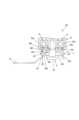
まず、図1~図13を参照して、第1実施形態について説明する。なお、本実施形態では、作業工具として、先端工具91を揺動駆動して、被加工材(図示せず)に対して加工作業を行う電動式の振動工具101を例示する(図1参照)。振動工具101には、装着可能な先端工具91として、ブレード、スクレーパ、研削パッド、研磨パッド等の複数種類が用意されている。使用者は、これらの先端工具91のうち、切断、剥離、研削、研磨等、所望の加工作業に適した1つを選択して振動工具101に装着し、加工作業を行うことができる。なお、以下で参照する図面では、先端工具91の一例として、ブレードが振動工具101に装着された例が図示されている。[First embodiment]
First, a first embodiment will be described with reference to FIGS. 1 to 13. FIG. In this embodiment, an
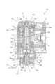
まず、振動工具101の概略構成について説明する。図1および図2に示すように、振動工具101は、長尺状のハウジング(工具本体ともいう)10を備えている。ハウジング10内には、スピンドル5、モータ3、駆動機構4等が収容されている。スピンドル5は、ハウジング10の長軸方向における一端部に収容されている。また、スピンドル5は、ハウジング10の長軸に交差する(詳細には、直交する)駆動軸A1に沿って配置されている。スピンドル5は、軸方向の一端部がハウジング10から突出し、外部へ露出している。この部分には、先端工具91を着脱可能である。また、ハウジング10の長軸方向における他端部には、モータ3への給電用のバッテリ93が着脱可能である。スピンドル5は、駆動機構4を介して伝達されるモータ3の動力によって、駆動軸A1周りに所定の角度範囲内で往復回動される。これにより、スピンドル5に取り付けられた先端工具91が所定の角度範囲内で揺動され、被加工材に対する加工作業が行われる。 First, a schematic configuration of the
なお、以下の説明では、便宜上、振動工具101の方向に関し、駆動軸A1方向を上下方向と定義し、先端工具91が装着されるスピンドル5の一端部側を下側、反対側を上側と定義する。また、駆動軸A1に直交し、且つ、ハウジング10の長軸方向に対応する方向を前後方向と定義し、スピンドル5が収容されているハウジング10の一端部側を前側、バッテリ93が装着される他端部側を後側と定義する。また、駆動軸A1およびハウジング10の長軸に直交する方向を、左右方向と定義する。 In the following description, for convenience, regarding the direction of the
以下、振動工具101の詳細構成について説明する。 A detailed configuration of the
まず、ハウジング10について説明する。図1および図2に示すように、ハウジング10は、振動工具101の外郭を形成する長尺状の筐体である。ハウジング10の前端部には、スピンドル5が収容されている。ハウジング10の略中央部には、モータ3が収容されている。モータ3とスピンドル5の間には、駆動機構4が収容されている。ハウジング10の中央部は、使用者によって把持される把持部13を構成している。ハウジング10の上面には、使用者が把持部13を把持した状態で操作可能なスライド式のスイッチ15が配置されている。本実施形態では、スイッチ15がオン位置に切り替えられると、モータ3が駆動される。ハウジング10の後端部には、充電式のバッテリ93が着脱されるバッテリ装着部17が設けられている。なお、バッテリ93およびバッテリ装着部17の構成については周知であるため、ここでの説明は省略する。 First, the
以下、モータ3、駆動機構4、スピンドル5、およびその他の内部機構について、順に説明する。 The
図2に示すように、モータ3は、モータシャフト31の回転軸がスピンドル5の駆動軸A1に直交するように配置されている。つまり、モータシャフト31の回転軸は、ハウジング10の長軸に沿って、前後方向に延在している。 As shown in FIG. 2, the
駆動機構4は、モータ3の動力によって、スピンドル5を駆動軸A1周りの所定の角度範囲内で往復回動させるように構成されている。図2に示すように、本実施形態の駆動機構4は、偏心シャフト41と、揺動アーム43と、駆動ベアリング45とを備えている。なお、このような構成の駆動機構4については周知であるため、ここでは簡単に説明する。偏心シャフト41は、モータシャフト31に連結されており、モータシャフト31の回転軸に対して偏心した偏心部411を有する。偏心部411の外周部には、駆動ベアリング45が取り付けられている。揺動アーム43は、駆動ベアリング45とスピンドル5とを接続する部材である。揺動アーム43の一端部は、環状に形成され、スピンドル5の外周部に固定されている。一方、揺動アーム43の他端部は、二股状に形成され、左右から駆動ベアリング45の外周部に当接するように配置されている。 The
図3に示すように、スピンドル5は、上下方向に延在する中空の円筒状部材である。スピンドル5の内部には、スピンドル5の下端の開口を通して、後述のクランプシャフト6(詳細には、シャフト部61)を挿入可能である。スピンドル5は、ハウジング10の前端部内で、駆動軸A1周りに回転可能に支持されている。より詳細には、スピンドル5の上端部および下端部は、ハウジング10に固定された2つのベアリング501、502によって支持されている。上述の揺動アーム43の一端部は、ベアリング501、502の間でスピンドル5の外周部に固定されている。スピンドル5の下端部(ベアリング502よりも下側の部分)は、ハウジング10から外部へ露出している。 As shown in FIG. 3, the
図3および図4に示すように、スピンドル5は、小径部51と、大径部53と、工具装着部55とを含む。 As shown in FIGS. 3 and 4 , the
小径部51は、クランプシャフト6のシャフト部61が挿入される部分であって、シャフト部61の径より僅かに大きい内径を有する。大径部53は、小径部51の上端部に接続して上方に延びる部分であって、小径部51よりも大きい内径を有する。大径部53は、一対のピン係合溝54を有する。一対のピン係合溝54は、夫々、径方向にスピンドル5を貫通する貫通孔であって、駆動軸A1を基準として180度の回転対称となるように(2回対称となるように)配置されている。各ピン係合溝54は、駆動軸A1および駆動軸A1に直交する仮想的な平面に対して斜めに延在する第1部分541と、駆動軸A1方向に(上下方向に)延在する第2部分542とを含む。なお、本実施形態では、駆動軸A1に直交する仮想的な平面に対する第1部分541の傾斜角は、7~10度程度に設定されている。ピン係合溝54には、後述の係合ピン75の両端部(詳細にはローラ76)が係合している。 The
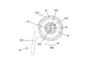
工具装着部55は、小径部51の下端部から、径方向外側に突出するフランジ状の部分である。工具装着部55は、ワッシャ503を挟んでベアリング502の下側に配置され、小径部51の外周部に圧入されている。工具装着部55には、クランプシャフト6を介して先端工具91が取り外し可能に装着される。本実施形態では、工具装着部55の下端部には、上方に凹む凹部550が形成されている。なお、凹部550は、下側からみた場合、駆動軸A1を中心とする略星形に形成されている(図5参照)。一方、図3に示すように、本実施形態の振動工具101に装着可能な先端工具91(ブレード、スクレーパ、研削パッド、研磨パッド等)は何れも、凹部550に概ね整合する形状を有し、凹部550に嵌合可能な凸部910を有する。凹部550と凸部910は、夫々、駆動軸A1に対して傾斜する傾斜面551、911を含む。傾斜面551、911は、凸部910が凹部550に嵌合されたときに互いに当接し、動力伝達面として機能する。本実施形態では、先端工具91は、傾斜面551、911が当接した状態で、工具装着部55と、クランプシャフト6のクランプヘッド63とによってクランプされ、スピンドル5に対して固定される。スピンドル5に対する先端工具91の固定およびその解除については、後で詳述する。 The
また、図3および図5に示すように、工具装着部55には、先端工具91の容易な取り外しを可能とするための付勢機構57が設けられている。付勢機構57は、ボール保持孔554内に配置された付勢バネ571と、ボール573とを含む。ボール保持孔554は、上下方向に工具装着部55を貫通する貫通孔である。本実施形態では、ボール保持孔554は、駆動軸A1周りの周方向において、等間隔で3つ設けられており、各ボール保持孔554に付勢バネ571とボール573とが配置されている。つまり、付勢機構57は、3組の付勢バネ571およびボール573を含む。付勢バネ571は、圧縮コイルバネであって、その軸線が上下方向に延在するように配置されている。ボール573は、付勢バネ571の下側に配置されている。付勢バネ571は、上端部がワッシャ503に当接し、下端部がボール573に当接して圧縮された状態で保持され、常時、ボール573を下方に付勢している。なお、図6に示すように、ボール573がボール保持孔554内で最下方位置に配置されると、ボール573の一部は、工具装着部55の下面(凹部550の天面)よりも下側(先端工具91側)に突出する。付勢機構57の作用については、後で詳述する。 In addition, as shown in FIGS. 3 and 5, the
更に、図3に示すように、上下方向において、小径部51と大径部53の間には、両者を区画する区画壁52が設けられている。区画壁52の中央部には、区画壁52を上下方向に貫通する位置決め孔521が設けられている。位置決め孔521は、左右方向に長い長穴として構成されており、位置決め孔521の前端および後端は、互いに平行な一対の平面によって規定されている。 Furthermore, as shown in FIG. 3, a
以下、クランプシャフト6の構成について説明する。本実施形態のクランプシャフト6は、スピンドル5に着脱可能な長尺部材として構成されている。以下では、クランプシャフト6の方向については、スピンドル5に挿入された状態を基準として説明する。図3および図4に示すように、本実施形態のクランプシャフト6は、シャフト部61と、クランプヘッド63と、位置決め部65と、ネック部66と、ロック部67とを含む。 The configuration of the
シャフト部61は、円柱状に形成されている。シャフト部61は、スピンドル5の小径部51に、スピンドル5と同軸状に挿入される部分である。シャフト部61の上端部の外周には、環状の溝が形成されており、この溝に環状の弾性部材(いわゆるOリング)69が装着されている。弾性部材69は、シャフト部61が小径部51に挿入された場合、小径部51の内周面に当接し、摩擦力を生じさせる(摩擦接触する)ことで、自重によるクランプシャフト6の落下を抑制するように構成されている。 The
クランプヘッド63は、シャフト部61の下端部から径方向外側に突出したフランジ状の部分である。クランプヘッド63は、工具装着部55の下側に配置され、工具装着部55と共に先端工具91をクランプするように構成されている。 The
位置決め部65は、シャフト部61と同軸状に、シャフト部61の上端部から上方に延びる長尺状の部分である。位置決め部65は、スピンドル5の位置決め孔(長穴)571に整合する断面形状を有している。つまり、位置決め部65の外周面は、軸線(駆動軸A1)を中心として互いに平行に対向する一対の平面651を含む。平面651間の距離は、位置決め孔521の幅(前端および後端を規定する一対の平面間の距離)よりも僅かに小さく設定されている。また、位置決め部65の最大径は、シャフト部61の径と概ね等しく、位置決め孔521の最大径よりも僅かに小さく設定されている。 The positioning
ネック部66は、シャフト部61と同軸状に、位置決め部65から上方に延びる部分であって、シャフト部61よりも小径の円柱状に形成されている。ネック部66の径は、位置決め部65の平面651間の距離と概ね等しく、位置決め孔521の幅よりも僅かに小さく設定されている。 The
ロック部67は、ネック部66の上端部に接続する部分であって、概ね矩形ブロック状に形成されている。駆動軸A1に直交する方向におけるロック部67の長さは、ネック部66の径よりも大きく、ロック部67の両端部は、ネック部66よりも径方向外側へ突出している。ロック部67は、上から見た場合、位置決め部65と概ね整合する形状を有する。つまり、ロック部67の外周面(側面)は、軸線(駆動軸A1)を中心として互いに平行に対向する一対の平面671を含む。ロック部67の平面671間の距離は、位置決め部65の平面651間の距離と等しく、位置決め孔521の幅よりも僅かに小さく設定されている。ロック部67の最大径は、シャフト部61の径と概ね等しく、位置決め孔521の最大径よりも僅かに小さく設定されている。 The
このような構成により、位置決め部65およびロック部67は、駆動軸A1周りの周方向において、スピンドル5に対して特定の位置に配置された場合にのみ、位置決め孔521を通過することが可能である。また、詳細は後述するが、位置決め部65が位置決め孔521に挿入されると、位置決め孔521の前端および後端を規定する一対の平面が、位置決め部65の一対の平面651に対向し、クランプシャフト6の駆動軸A1周りの位置決め部65の回転を規制する(図3参照)。つまり、位置決め部65が位置決め孔521に挿入されると、クランプシャフト6は、駆動軸A1周りの周方向において位置決めされた状態で保持されることになる。 With such a configuration, the positioning
以下、スピンドル5の大径部53内に配置された保持機構7の構成について説明する。保持機構7は、クランプシャフト6を上方に付勢した状態でスピンドル5に対して固定状に保持するように構成された機構である。図3および図4に示すように、本実施形態の保持機構7は、保持シャフト71と、係合ピン75と、付勢バネ77とを主体として構成されている。 The configuration of the
保持シャフト71は、駆動軸A1に沿って上下方向に延びる長尺状の部材であって、スピンドル5の大径部53内にスピンドル5と同軸状に配置されている。保持シャフト71は、スピンドル5に対して上下方向に移動可能、且つ、駆動軸A1周りに回動可能に配置されている。保持シャフト71は、大径部711と、小径部715と、レバー係合部717とを含む。 The holding
大径部711は、保持シャフト71の下端部を構成する部分である。大径部711は、スピンドル5の大径部53の内径と概ね等しい外径を有し、大径部53の内周面に沿って摺動可能である。小径部715は、大径部711から上方に延在する部分であって、大径部711よりも小径に形成されている。レバー係合部717は、小径部715から上方に突出し、矩形状の断面を有する部分であって、保持シャフト71の上端部を構成する。なお、小径部715とレバー係合部717は1本のベースシャフト701として形成されている一方、大径部711は、有底の円筒部材702がベースシャフト701の下端部に圧入固定されることで形成されている。このとき、円筒部材702の底壁部(下壁部)703がベースシャフト701の下端から下方に離間した位置に配置されることで、保持シャフト71の下端部内には、空間710が形成されている(図3参照)。空間710は、クランプシャフト6のロック部67の挿入、および、その駆動軸A1周りの相対的な回動を許容する。 The
また、図3および図7に示すように、底壁部703には、ロック孔714が設けられている。ロック孔714は、底壁部703を上下方向に貫通する、周囲が閉じた貫通孔である。ロック孔714は、上述のスピンドル5の位置決め孔521と概ね同一の断面形状を有する長穴として構成されている。つまり、ロック孔714も、ロック部67よりも僅かに大きく、ロック部67に整合する断面形状を有する。よって、ロック部67は、図8に示すように、駆動軸A1周りの周方向において、保持シャフト71に対して特定の位置に配置された場合にのみ、ロック孔714を上下方向に通過することが可能である。 Further, as shown in FIGS. 3 and 7, the
ロック部67がロック孔714を通って空間710内に配置された後、ロック部67と保持シャフト71とが特定の角度範囲内で相対的に回動すると、図7に示すように、ロック部67はロック孔714を通過不能となり、保持シャフト71に係合する。具体的には、底壁部703の上面704の一部(詳細には、ロック孔714の周囲の領域)が、面接触によりロック部67の下面673と係合する。つまり、底壁部703の上面704のうち、ロック孔714の周囲の領域は、係合面(受け面)として機能する。ロック部67と保持シャフト71の係合によって、クランプシャフト6は保持シャフト71に連結される。なお、本実施形態のロック部67とロック孔714との関係では、回動角度範囲は、0度よりも大きく180度よりも小さければロック部67は保持シャフト71に係合可能であるが、より確実な係合のためには、15度~90度であることが好ましく、30度~90度であることがより好ましい。ロック部67の動作効率と確実な係合とのバランスを考慮すると、回動角度は、概ね30度~60度であることが更に好ましい。 After the locking
なお、以下では、保持シャフト71に対するクランプシャフト6(ロック部67)の周方向位置については、ロック部67がロック孔714を通過可能な位置(図8に示す位置)を、アンロック位置といい、ロック部67がロック孔714を通過不能であって、保持シャフト71に係合可能な位置(例えば、図7に示す位置)を、ロック位置という。本実施形態では、周方向における保持シャフト71とクランプシャフト6(ロック部67)との相対的な位置関係は、後述の解除レバー81の操作、または、保持シャフト71へのクランプシャフト6の挿入に応じて変化する。この点については、後で詳述する。 In the following, regarding the circumferential position of the clamp shaft 6 (lock portion 67) with respect to the holding
また、図4に示すように、大径部711(詳細には、空間710の上側の部分)には、径方向(駆動軸A1に直交する方向)に大径部711を貫通する貫通孔713が設けられている。係合ピン75は、小径の円柱状部材であって、貫通孔713に嵌合されている。係合ピン75は、大径部711の外径よりも長く、係合ピン75の両端部は、大径部711から外側に突出している。係合ピン75の両端部には、ローラ76が回転可能に支持されている。図9に示すように、係合ピン75は、ローラ76を介してピン係合溝54に係合している。 Further, as shown in FIG. 4, the large diameter portion 711 (specifically, the upper portion of the space 710) has a through
本実施形態では、付勢バネ77として、圧縮バネおよび捩りバネの両機能を備えたコイルバネが採用されている。図3および図4に示すように、付勢バネ77は、保持シャフト71の小径部715に外装されて、上下方向に延在している。付勢バネ77の下端部(作動端部)は、保持シャフト71の小径部715に設けられた係止溝716(図6参照)に係止される。付勢バネ77の上端部(固定端部)は、スピンドル5に設けられた係止溝531(図4参照)に係止される。付勢バネ77の上側には、円筒状のバネ受け部材537が配置されている。バネ受け部材537は、大径部53に嵌合され、止め輪539によって上方への移動が規制されている。 In this embodiment, a coil spring having both functions of a compression spring and a torsion spring is employed as the biasing
保持機構7は、付勢バネ77が保持シャフト71の大径部711の上端とバネ受け部材537の下端の間で圧縮され、且つ、上から見て時計回り方向に捩られた状態(軸方向および捩り方向の負荷がかけられた状態)で、図3および図9に示すようにスピンドル5に組み付けられている。これにより、保持シャフト71は、下方、且つ、上から見て反時計回り方向に付勢されている。そして、軸方向力と捩り力とが釣り合う位置で、係合ピン75がローラ76を介してピン係合溝54の第1部分541(詳細には、第1部分541を規定する傾斜面)に係合することで、スピンドル5に対する保持シャフト71の軸方向の移動および駆動軸A1周りの回動が規制される。このとき、保持シャフト71は、付勢バネ77の捩り力によって、上方に付勢された状態で保持される。以下では、このときの保持シャフト71の位置を、クランプ位置という。 In the
保持シャフト71がクランプ位置に配置されると、ロック部67を介して保持シャフト71に連結されたクランプシャフト6は、上方に付勢された状態でスピンドル5に対して固定状に保持され、工具装着部55とクランプヘッド63によって先端工具91がクランプされる。なお、保持シャフト71がクランプ位置に配置されているときには、ロック部67は、ベースシャフト701の下端から僅かに下方に離間している。 When the holding
更に、図3に示すように、本実施形態では、スピンドル5の上側には、保持シャフト71を駆動軸A1周りに回動させるように構成された解除機構8が設けられている。詳細は後述するが、保持シャフト71が解除機構8によってクランプ位置からアンクランプ位置に移動されることで、保持シャフト71からクランプシャフト6を取り外すことが可能となる。 Furthermore, as shown in FIG. 3, in this embodiment, above the
以下、解除機構8の構成について説明する。図3および図4に示すように、本実施形態の解除機構8は、解除レバー81と、付勢バネ83とを主体として構成されている。 The configuration of the
解除レバー81は、使用者による回動操作が可能な状態で、ハウジング10に支持されている。本実施形態では、解除レバー81は、ハウジング10の前端部の上面に配置された上側部材811と、上側部材811に連結されて下方に突出する下側部材815とによって形成されている。上側部材811は、平面視円形のベース部812と、ベース部812から概ね法線方向に突出するレバー部813とを含む。下側部材815は、段付きの筒状部材として構成されている。下側部材815の上側部分は、外径がより小さい小径部とされており、ベース部812に設けられた円筒孔に嵌合可能である。本実施形態では、上側部材811および下側部材815は、ハウジング10に固定された筒状の保持スリーブ87を上下から挟んだ状態で、互いに相対回動不能に嵌合され、ネジで固定されている。これにより、上側部材811および下側部材815は、解除レバー81として一体化され、保持スリーブ87によって、駆動軸A1周りに回動可能に支持されている。 The
また、図10に示すように、下側部材815の内側には、駆動軸A1周りの周方向の2箇所に、係合部816が設けられている。図3に示すように、保持シャフト71がクランプ位置で保持されているときには、レバー係合部717は、バネ受け部材537よりも上方に突出して、下側部材815の内部に配置される。係合部816は、保持シャフト71のレバー係合部717の側面に対して当接可能な凸部として構成されている。 As shown in FIG. 10, engaging
本実施形態では、付勢バネ83として、捩りコイルバネが採用されている。図3に示すように、付勢バネ83は、保持スリーブ87およびベース部812の円筒部に外装されている。詳細な図示は省略するが、付勢バネ83の下端部(固定端部)は、保持スリーブ87に係止されており、上端部(作動端部)は、ベース部812に係止されている。付勢バネ83は、上から見て時計回り方向に捩られた状態(捩り方向の負荷がかけられた状態)で解除レバー81に組み付けられる。これにより、解除レバー81は、上から見て反時計回り方向に付勢され、レバー部813が後方に延在してハウジング10の左側面に当接する位置で保持される(図1参照)。以下、このときの解除レバー81の位置を、初期位置という。 In this embodiment, a torsion coil spring is employed as the biasing
以下、先端工具91の取り外し時および装着時の保持機構7、解除機構8、および付勢機構57の動作について説明する。 The operations of the
まず、先端工具91の取り外しについて説明する。 First, removal of the
図3、図7、図9、および図10に示すように、解除レバー81が初期位置に配置され、保持シャフト71がクランプ位置に配置されている場合、保持シャフト71のレバー係合部717は、解除レバー81の下側部材815の内側で、係合部816から周方向の押圧を受けることなく保持されている。また、上述のように、係合ピン75の両端部(ローラ76)は、ピン係合溝54の第1部分541に係合している。更に、ロック部67がロック位置に配置され、下面673が上面704に面接触した状態で底壁部703に係合することで、クランプシャフト6は、ロック部67を介して保持シャフト71に連結されている。これにより、クランプシャフト6が上方に付勢された状態でスピンドル5に対して固定状に保持され、工具装着部55とクランプヘッド63によって先端工具91がクランプされている。 3, 7, 9, and 10, when the
このとき、付勢機構57のボール573は、付勢バネ571によって下方へ付勢され、先端工具91の凸部910の上面に当接して先端工具91を押圧する。一方、付勢バネ77は、保持シャフト71を介してクランプシャフト61を上方へ付勢することで、工具装着部55とクランプヘッド63の間で先端工具91をクランプするクランプ力を付与する。このクランプ力は、付勢バネ571による下方への付勢力を上回っている。このため、先端工具91は、付勢バネ571による下方への付勢にもかかわらず、工具装着部55とクランプヘッド63との間で上下方向に移動不能にクランプされる。つまり、先端工具91は、付勢バネ571の付勢力で工具装着部55から外れることなく、工具装着部55とクランプヘッド63によって強固にクランプされた状態で保持される。 At this time, the
この状態から、使用者によってレバー部813が把持され、解除レバー81が、初期位置から、付勢バネ83の付勢力に抗して時計回り方向(図10の矢印CW方向)に回動される。この過程で、係合部816がレバー係合部717に当接し、付勢バネ77の付勢力に抗して、保持シャフト71を解除レバー81と同じ方向(上から見て時計回り方向)に回動させる。ピン係合溝54の第1部分541に係合した係合ピン75は、保持シャフト71の回動に伴って、第1部分541内を斜め下方へ移動する。このとき、ローラ76が第1部分541内を転動することで、係合ピン75は第1部分541に沿って案内される。これにより、保持シャフト71は、スピンドル5に対して、駆動軸A1周りに回動しつつ下方へ移動する。解除レバー81および保持シャフト71の回動に伴って、付勢バネ83および付勢バネ77には、夫々、捩り力(トルク)が作用する。 From this state, the user grips the
図11に示すように、解除レバー81が、初期位置から時計回り方向に概ね90度の位置(以下、回動位置という)まで回動されると、係合ピン75の端部(ローラ76)が、斜めに延びる第1部分541と、上下方向に延びる第2部分542の接続部分に到達する。すると、予め圧縮されていた付勢バネ77の軸方向の復元力によって、保持シャフト71が下方へ付勢される。係合ピン75は、ローラ76を介して第2部分542に係合し、第2部分542に沿って下方へ案内される。なお、保持シャフト71は、付勢バネ77の捩り方向の復元力によって、上から見て反時計回り方向にも付勢されるが、ローラ76を介して係合ピン75が第2部分542に係合することで、保持シャフト71の回動は規制される。このため、保持シャフト71は、下方へ直線状に移動する。保持シャフト71の下方への移動に伴って、工具装着部55とクランプヘッド63による先端工具91のクランプが解除される。 As shown in FIG. 11, when the
図12に示すように、保持シャフト71は、係合ピン75が第2部分542の下端に当接する位置まで移動し、付勢バネ77の軸方向の付勢力によって、この位置で保持される。以下、このときの保持シャフト71の位置をアンクランプ位置という。図6に示すように、アンクランプ位置では、保持シャフト71のレバー係合部717は、解除レバー81の係合部816から下方に離間している。 As shown in FIG. 12, the holding
なお、解除レバー81の回動に伴って、保持シャフト71はスピンドル5に対して駆動軸A1周りに回動するが、クランプシャフト6はスピンドル5に対して回動不能に保持されている。よって、保持シャフト71に対するクランプシャフト6の周方向位置が変化する。なお、本実施形態では、解除レバー81の初期位置から回動位置までの回動角度(時計回り方向をプラスとする)は、概ね90度であるのに対し、保持シャフト71のクランプ位置からアンクランプ位置までの回動角度、つまり、ロック部67のアンロック位置からロック位置までの回動角度は、概ね30~60度の範囲内に設定されている。 As the
保持シャフト71がクランプ位置からアンクランプ位置まで回動されると、クランプシャフト6は、図7に示すロック位置から、図8に示すように、ロック部67が保持シャフト71のロック孔714を通過可能なアンロック位置へ相対的に移動する。これにより、保持シャフト71とクランプシャフト6の係合が解除され、クランプシャフト6の下方向への移動が許容される。また、このとき、ロック孔714とスピンドル5の位置決め孔521とは上下に重なり合う位置に配置されている。よって、保持シャフト71およびスピンドル5からのクランプシャフト6の取り外し(引き抜き)が可能となる。 When the holding
解除レバー81の回動に伴って、保持シャフト71がクランプ位置からアンクランプ位置へ向けて下方へ移動する過程で、ベースシャフト701の下端がロック部67の上端に当接し、クランプシャフト6を押圧して下方へ移動させる。上述のように、クランプシャフト6の回動は規制されているため、クランプシャフト6は回動することなく下方へ直線状に移動する。このとき、シャフト部61の外周部に装着された弾性部材69の摩擦力により、クランプシャフト6は、自重で落下することなく小径部51内を摺動する。そして、図6に示すように、保持シャフト71がアンクランプ位置まで到達しても、クランプシャフト6は、小径部51に挿入された状態で保持される。使用者は、先端工具91と共にクランプシャフト6をスピンドル5および保持シャフト71から引き抜くことで、先端工具91を取り外すことができる。 As the
なお、付勢バネ77による上方への付勢力が解除され、保持シャフト71およびクランプシャフト6が下方へ移動する過程で、付勢バネ571によって下方に付勢されたボール573が、先端工具91を上方から押圧する。先端工具91は、クランプヘッド63によって下方から工具装着部55に押し付けられ、傾斜面911と傾斜面551とが当接した状態で揺動駆動されると、凸部910が凹部550に嵌合した状態で固着してしまう場合がある。このような場合、先端工具91の固着が比較的弱ければ、付勢機構57は、凸部910を凹部550から押し出すことができる。また、先端工具91の固着が比較的強い場合でも、付勢機構57が先端工具91を下方へ押圧することで、使用者が先端工具91を把持して取り外すことがより容易となる。このように、付勢機構57は、先端工具91の固着を少なくとも緩和することができる。 When the upward biasing force of the biasing
保持シャフト71がアンクランプ位置に配置された状態で、使用者がレバー部813の把持を解除すると、解除レバー81の回動位置への回動時に付勢バネ83に付与された捩り力に対応する復元力によって、解除レバー81は初期位置へ向けて反時計回り(図11の矢印CCW方向)に回動する。このとき、上述したように、保持シャフト71のレバー係合部717は、解除レバー81の係合部816から下方に離間している(図6参照)。また、係合ピン75の両端部(ローラ76)が、ピン係合溝54の第2部分542に係合することで、保持シャフト71の回動が規制されている。よって、図13に示すように、解除レバー81が初期位置に戻っても、保持シャフト71は回動せず、アンクランプ位置で保持されることになる。これにより、使用者は、解除レバー81を離した状態で、クランプシャフト6および先端工具91を容易に取り外すことができる。 When the user releases the grip of the
次に、先端工具91の取付けについて説明する。 Next, attachment of the
先端工具91の取付け時には、上述のように、保持シャフト71は、付勢バネ77の軸方向の付勢力によってアンクランプ位置に保持されており、クランプシャフト6は取り外された状態である。使用者はまず、所望の加工作業に応じた先端工具91を選択し、先端工具91の凸部910の中央部に設けられた貫通孔にクランプシャフト6を挿通する。そして、スピンドル5および保持シャフト71に対するクランプシャフト6の周方向位置を調整し、ロック部67側から、クランプシャフト6をスピンドル5および保持シャフト71に挿入する。具体的には、使用者は、ロック部67および位置決め部65が、スピンドル5の位置決め孔521を通過可能、且つ、ロック部67が保持シャフト71のロック孔714を通過可能な位置に、クランプシャフト6を位置決めする。なお、上述のように、アンクランプ位置では、保持シャフト71はスピンドル5に対して回動不能に保持されており、位置決め孔521とロック孔714は、上下方向に重なる位置にある。よって、このときの位置決めは、周方向において、ロック部67をアンロック位置に配置することと同義である。 When the
クランプシャフト6をアンロック位置に配置して、スピンドル5および保持シャフト71に対して上方へ移動させると、図6に示すように、ロック部67がロック孔714を通って保持シャフト71下端部の空間710内に進入する。そして、ロック部67の上端がベースシャフト701の下端に当接し、付勢バネ77の軸方向の付勢力に抗して保持シャフト71を上方に押し上げる。ローラ76を介して第2部分542に係合した係合ピン75(図12参照)は、第2部分542内を、第1部分541との接続部に向かって上方へ移動する。 When the
係合ピン75が、第2部分542と第1部分541の接続部に到達すると、解除レバー81の回動位置への回動時に付勢バネ77に付与された捩り力に対応する復元力によって、保持シャフト71は、スピンドル5に対して、上から見て反時計回り方向に回動し、係合ピン75は、第1部分541内を斜め上方に移動する。そして、係合ピン75(ローラ76)が、捩り力と軸方向力が釣り合う位置で第1部分541(傾斜面)に係合し、保持シャフト71は、クランプ位置に復帰して保持される。 When the engaging
この間、位置決め部65が位置決め孔521内に配置されることで、スピンドル5に対するクランプシャフト6の回動は規制されている。よって、保持シャフト71がスピンドル5に対して駆動軸A1周りに回動するのに伴って、保持シャフト71に対するロック部67の周方向位置が、アンロック位置(図8参照)からロック位置(図7参照)へと変化する。その結果、ロック部67が保持シャフト71に係合することで、クランプシャフト6が保持シャフト71に連結される。よって、保持シャフト71がクランプ位置に復帰すると、クランプシャフト6は上方に付勢された状態でスピンドル5に対して固定状に保持されて、工具装着部55とクランプヘッド63によって先端工具91がクランプされる。なお、クランプシャフト6および先端工具91が上方へ移動する過程で、最下方位置に配置されていたボール573は、先端工具91の凸部910の上面に当接して、付勢バネ571の付勢力に抗して押し上げられ、上述のように、先端工具91を上方から押圧する状態で保持される(図3参照)。 During this time, the rotation of the
以上に説明したように、本実施形態の振動工具101では、先端工具91は、傾斜面911が傾斜面551に押し付けられた状態でクランプされる。このような状態で先端工具91が揺動駆動されると、先端工具91が工具装着部55に固着してしまう場合がある。これに対し、本実施形態では、工具装着部55に設けられた付勢機構57によって、工具装着部55に対する先端工具91の固着を少なくとも緩和し、先端工具91の容易な取り外しを実現することができる。 As described above, in the
特に、本実施形態では、付勢機構57は、駆動軸A1周りの周方向において等間隔で配置された3つの付勢バネ571を含む。よって、先端工具91を駆動軸A1の周囲でバランスよく付勢し、工具装着部55に対する先端工具91の固着をより確実に解消または緩和することができる。また、各付勢バネ571は圧縮コイルバネであって、その下側に上下方向に移動可能に配置されたボール573を介して先端工具91を下方に付勢する。よって、付勢バネ571が先端工具91に当接して付勢する場合に比べ、付勢バネ571の耐久性を高めることができる。 In particular, in this embodiment, the
更に、本実施形態では、振動工具101は、クランプ位置とアンクランプ位置との間で、スピンドル5に対して上下方向に移動可能な保持シャフト71を備えている。そして、保持シャフト71は、クランプ位置およびアンクランプ位置の夫々において、付勢バネ77の付勢力によって保持される。つまり、解除レバー81の回動操作が解除されても、保持シャフト71がクランプ位置に自動的に復帰することがない。更に、保持シャフト71は、アンクランプ位置に配置されているときにシャフト部61がスピンドル内に挿入されるのに応じて、クランプ位置へ移動する。よって、使用者は、シャフト部61をスピンドル5に挿入する操作のみで(つまり、ワンタッチで)、保持シャフト71をクランプ位置へ移動させ、クランプシャフト6をスピンドル5に固定状に保持させることができる。また、使用者は、上述のようにワンタッチで先端工具91の取付けを行うだけで、付勢機構57の付勢バネ571を更に圧縮し、先端工具91を下方に付勢する状態とすることができる。 Furthermore, in this embodiment, the
[第2実施形態]
以下、図14~図18を参照して、第2実施形態に係る振動工具102について説明する。本実施形態の振動工具102の構成の大部分は、第1実施形態の振動工具101(図1~図4参照)と実質的に同一であるが、工具装着部56の構成が異なる。よって、以下では、第1実施形態と同一の構成については、同一の符号を付して、適宜、その説明および図示を省略または簡略化し、主に、工具装着部56の構成および作用について説明する。[Second embodiment]
A
図14に示すように、工具装着部56は、第1実施形態の工具装着部55(図3参照)と同様、フランジ状の部分であって、ワッシャ503を挟んでベアリング502の下側に配置され、小径部51の外周部に圧入されている。工具装着部56の下端部には、先端工具91の凸部910が嵌合可能な凹部550が形成されている。先端工具91は、傾斜面551、911が当接した状態で、工具装着部56と、クランプシャフト6のクランプヘッド63とによってクランプされ、スピンドル5に対して固定される。 As shown in FIG. 14, the
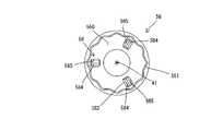
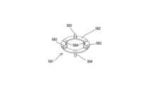
また、図14~図17に示すように、工具装着部56には、先端工具91の容易な取り外しを可能とするための付勢機構58が設けられている。本実施形態では、付勢機構58は、工具装着部56のバネ収容部563内に配置された付勢バネ581を含む。バネ収容部563は、工具装着部56の上面から下方に凹む環状の凹部564と、凹部564の底面から工具装着部56の下面(凹部550の天面)まで、工具装着部56を上下方向に貫通する3つの貫通孔565とを含む。貫通孔565は、周方向において等間隔で設けられている。本実施形態では、付勢バネ581は、全体としては円環状の板バネである。付勢バネ581は、凹部564に嵌合可能な円環状のベース部582と、ベース部582から屈曲して上方に突出する3つの凸部583と、ベース部582から屈曲して下方に突出する3つの凸部584とを含む。凸部583は、周方向において等間隔で配置されている。また、凸部584も、周方向において等間隔で配置されている。なお、各凸部584は、隣接する2つの凸部583の中間位置に配置されている。つまり、凸部583および凸部584は、周方向において、等間隔で交互に配置されている。付勢バネ581は、ベース部582が撓むことで、上下方向に弾性変形するように構成されている。 In addition, as shown in FIGS. 14 to 17, the
付勢バネ581は、凸部583の上端がワッシャ503に当接し、凸部584が貫通孔565内に配置された状態で、バネ収容部563に収容されている。なお、図18に示すように、付勢バネ581に上方への外力が加えられていない状態では、ベース部582の下面が凹部564の底面に当接し、凸部584が貫通孔565内で最下方位置に配置される。このとき、凸部584の下端部は、工具装着部56の下面(凹部550の天面)よりも下側(先端工具91側)に突出する。 The urging
本実施形態の付勢機構58は、第1実施形態の付勢機構57と同様、先端工具91の容易な取り外しを可能とするものである。具体的には、図14に示すように、工具装着部56とクランプヘッド63によって先端工具91がクランプされているときには、ベース部582が上方に撓んだ状態にあり、凸部584が先端工具91の凸部910の上面に当接して先端工具91を下方に付勢している。しかしながら、第1実施形態と同様、付勢バネ77によって付与されるクランプ力は、付勢バネ581による下方への付勢力を上回っている。このため、先端工具91は、付勢バネ581による下方への付勢にもかかわらず、工具装着部56とクランプヘッド63との間で上下方向に移動不能にクランプされる。つまり、先端工具91は、付勢バネ581の付勢力で工具装着部56から外れることなく、工具装着部56とクランプヘッド63によって強固にクランプされた状態で保持される。 The
一方、先端工具91の取り外し時には、付勢バネ77による上方への付勢力が解除され、保持シャフト71およびクランプシャフト6が下方へ移動する過程で、付勢バネ581の復元力によって、凸部584が先端工具91を上方から押圧する。よって、凸部910が凹部550に嵌合した状態で固着してしまった場合でも、先端工具91の固着が比較的弱ければ、付勢機構58(付勢バネ581)は、凸部910を凹部550から押し出すことができる。また、先端工具91の固着が比較的強い場合でも、付勢機構58が先端工具91を下方へ押圧することで、使用者が先端工具91を把持して取り外すことがより容易となる。このように、付勢機構58も、付勢機構57と同様、先端工具91の固着を少なくとも緩和することができる。 On the other hand, when the
なお、本実施形態でも、付勢機構58は、駆動軸A1周りの周方向において等間隔で配置された3つの凸部584を含む。よって、先端工具91を駆動軸A1の周囲でバランスよく付勢し、工具装着部56に対する先端工具91の固着をより確実に解消または緩和することができる。また、本実施形態では、3つの凸部584は、板バネである付勢バネ581の一部である。つまり、1つの板バネによって、複数箇所で先端工具91を下方へ付勢するための簡易な構成が実現されている。 In this embodiment, the
更に、先端工具91の取付け時には、クランプシャフト6および先端工具91が上方へ移動する過程で、最下方位置に配置されていた凸部584は、先端工具91の凸部910の上面に当接して、付勢バネ581の付勢力に抗して押し上げられる。これに伴い、ベース部582が上方へ撓む。先端工具91がクランプされると、凸部584は先端工具91を上方から押圧する状態で保持される。つまり、第1実施形態と同様、使用者は、ワンタッチで先端工具91の取付けを行うだけで、付勢機構58の付勢バネ581を弾性変形させ、先端工具91を下方に付勢する状態とすることができる。 Furthermore, when the
本実施形態の各構成要素と請求項の各構成要素の対応関係を以下に示す。振動工具101、102の各々は、「作業工具」の一例である。駆動軸A1は、「駆動軸」の一例である。スピンドル5は、「スピンドル」の一例である。工具装着部55、56の各々は、「スピンドルの下端部」の一例である。傾斜面551は、「第1傾斜面」の一例である。先端工具91および傾斜面911は、夫々、「先端工具」および「第2傾斜面」の一例である。クランプシャフト6は、「クランプシャフト」の一例である。シャフト部61は、「シャフト部」の一例である。クランプヘッド63は、「ヘッド部」の一例である。付勢バネ571は、「付勢部」、「圧縮コイルバネ」の一例である。ボール573は、「ボール」の一例である。付勢バネ581は、「板バネ」の一例である。凸部584は、「付勢部」、「凸部」の一例である。付勢バネ77は、「付勢部材」の一例である。保持シャフト71は、「保持部材」の一例である。保持シャフト71のクランプ位置、アンクランプ位置は、夫々、「保持位置」、「解放位置」の一例である。 Correspondence between each component of this embodiment and each component of the claims is shown below. Each of the
上記実施形態は単なる例示であり、本発明に係る作業工具は、例示された振動工具101、102の構成に限定されるものではない。例えば、下記に例示される変更を加えることができる。なお、これらの変更は、これらのうちいずれか1つのみ、あるいは複数が、実施形態に示す振動工具101、102の各々、あるいは各請求項に記載された発明と組み合わされて採用されうる。 The above embodiment is merely an example, and the work tool according to the present invention is not limited to the configurations of the
工具装着部56とクランプヘッド63によってクランプされた先端工具91を常時下方に付勢可能である限りにおいて、付勢機構57、58の構成は、適宜変更されうる。例えば、上記実施形態では、周方向において等間隔で3箇所に配置された3つの付勢部(付勢バネ571、凸部584)が先端工具91を下方に付勢する例が挙げられている。しかしながら、付勢機構57、58は、1つの付勢部のみを有してもよいし、2つ、または4つ以上の付勢部を有してもよい。また、例示された圧縮コイルバネまたは板バネに代えて、別の種類のバネ(例えば、皿バネ、捩りバネ)に変更されてもよい。 The configuration of the biasing
また、スピンドル5、クランプシャフト6、保持機構7、解除機構8の構成(例えば、構成部材、形状、配置、支持構造等)は、適宜変更されうる。以下に、採用可能な変形例を例示する。 Also, the configurations of the
例えば、上記実施形態では、シャフト部61をスピンドル5に挿入する操作のみで(つまり、ワンタッチで)、クランプシャフト6をスピンドル5に固定状に保持させ、先端工具91をクランプすることが可能な保持機構7が採用されている。このようなワンタッチ機能を有する保持機構は、保持機構7に限られるものではない。例えば、クランプシャフト6のロック部67およびロック孔714の構成は、適宜変更されてよい。また、例えば、保持機構7は、シャフト部61をスピンドル5に挿入する操作に応じて、クランプシャフト6に設けられた溝と、保持シャフト71に保持されたボールとが係合するように変更されてもよい。 For example, in the above-described embodiment, the
保持機構7は、必ずしもワンタッチ機能を有する必要はなく、解除レバー81のような操作部材の外部操作に応じて、先端工具91のクランプおよびクランプの解除を行うように構成されていてもよい。例えば、操作部材の操作に応じて、スピンドル5の径方向に移動可能なボール、または、複数の歯を有するクランプ部材を備えた保持機構が採用されてもよい。この場合、クランプシャフト6は、必ずしも保持シャフト71のような別部材を介して保持される必要はなく、ボールやクランプ部材によって直接保持されてもよい。また、上記実施形態では、付勢バネ77によってクランプシャフト6がスピンドル5に対して上方に付勢され、先端工具91がクランプされる。これに代えて、先端工具91は、例えばネジを用いてクランプシャフト6がスピンドル5に固定されることで、クランプされてもよい。スピンドル5の構成は、クランプシャフト6や保持機構7の構成に応じて適宜変更される。 The
解除レバー81は、駆動軸A1周りに回動されるのではなく、駆動軸A1に直交する方向(例えば、左右方向)に延在する回動軸周りに回動可能であってもよい。 The
ハウジング10、モータ3、および駆動機構4の構成についても、適宜、変更が可能である。例えば、ハウジング10は、モータ3、駆動機構4、スピンドル5を収容するインナハウジングと、インナハウジングに対して弾性連結されたアウタハウジングとを含むいわゆる防振ハウジングであってもよい。モータ3は、ブラシレスモータであってもよいし、モータシャフト31の回転軸が駆動軸A1と平行となるように、ハウジング10の前端部内に収容されていてもよい。また、例えば、振動工具101、102は、バッテリ93ではなく、外部の交流電源から供給される電力で動作するように構成されてもよい。 The configurations of the
更に、本発明および上記実施形態とその変形例の趣旨に鑑み、以下の態様が構築される。以下の態様は、独立して、あるいは、実施形態に示す振動工具101、102、上記変形例、または各請求項に記載された発明と組み合わされて採用されうる。 Furthermore, in view of the spirit of the present invention and the above-described embodiments and modifications thereof, the following aspects are constructed. The following aspects can be employed independently or in combination with the
[態様1]
前記少なくとも1つの付勢部は、少なくとも1つのバネである。
[態様2]
前記スピンドルの前記下端部は、前記上下方向に延在する少なくとも1つの凹部を有し、
前記少なくとも1つの付勢部および前記少なくとも1つのボールは、前記凹部内に配置されており、
前記少なくとも1つのボールの各々は、最下方位置に配置された場合、前記スピンドルの下面から突出する。
ボール保持孔554は、本態様の「凹部」の一例である。
[態様3]
前記板バネは、円環状のベース部と、前記ベース部から下方に突出する前記少なくとも1つの凸部を含み、
前記スピンドルの前記下端部は、前記ベース部が嵌合された円環状の凹部と、前記少なくとも1つの凸部が配置され、下方に開口する少なくとも1つの貫通孔を有し、
前記少なくとも1つの凸部は、最下方位置に配置された場合、前記スピンドルの下面から突出する。
ベース部582、凹部564、貫通孔565は、夫々、本態様の「ベース部」、「凹部」、「貫通孔」の一例である。
[態様4]
使用者による外部操作が可能な操作部材を更に備え、
前記保持部材は、前記操作部材の操作に応じて、前記保持位置から解放位置へ移動するように構成されている。
解除レバー81は、本発態様の「操作部材」の一例である。
[態様5]
前記付勢部材は、圧縮バネおよび捩りバネの両機能を備えたコイルバネであって、前記保持部材が前記解放位置に配置されているときには、圧縮に対応する復元力で前記保持部材を前記スピンドルに対して下方に付勢し、前記保持部材が前記保持位置に配置されているときには、捩りに対応する復元力で前記保持部材を前記スピンドルに対して上方へ付勢する。
[態様6]
前記スピンドルは、前記駆動軸に対して傾斜した傾斜溝を外周部に有し、
前記保持部材は、前記傾斜溝内に配置された凸部を有し、
前記付勢部材は、前記保持部材を前記駆動軸周りに回動付勢して前記凸部を前記傾斜溝に係合させることで、前記保持部材を前記保持位置で保持する。
ピン係合溝54(詳細には第1部分541)は、本態様の「傾斜溝」の一例である。係合ピン75は、本態様の「凸部」の一例である。
[態様7]
前記スピンドルは、前記傾斜溝の下端に接続して下方に延在する鉛直溝を有し、
前記付勢部材は、前記保持部材を前記スピンドルに対して下方に付勢して前記凸部を前記鉛直溝の下端に係合させることで、前記保持部材を前記解放位置で保持する。
ピン係合溝54の第2部分542は、本態様の「鉛直溝」の一例である。
[態様8]
前記保持部材が前記解放位置に配置されているときには、前記凸部が前記鉛直溝の周方向の端に当接することで、前記スピンドルに対する前記保持部材の回動を規制する。[Aspect 1]
The at least one biasing member is at least one spring.
[Aspect 2]
the lower end of the spindle has at least one concave portion extending in the vertical direction;
the at least one biasing portion and the at least one ball are disposed within the recess;
Each of the at least one ball protrudes from the lower surface of the spindle when positioned in the lowest position.
The
[Aspect 3]
the leaf spring includes an annular base portion and the at least one convex portion projecting downward from the base portion;
The lower end portion of the spindle has an annular concave portion in which the base portion is fitted, and at least one downwardly opening through hole in which the at least one convex portion is arranged,
The at least one protrusion protrudes from the lower surface of the spindle when arranged in the lowest position.
The
[Aspect 4]
further comprising an operation member that can be externally operated by the user,
The holding member is configured to move from the holding position to the release position in accordance with the operation of the operating member.
The
[Aspect 5]
The urging member is a coil spring having both functions of a compression spring and a torsion spring, and when the holding member is disposed at the release position, the holding member is pressed against the spindle with a restoring force corresponding to compression. When the holding member is in the holding position, a restoring force corresponding to torsion urges the holding member upward against the spindle.
[Aspect 6]
The spindle has an inclined groove on its outer periphery that is inclined with respect to the drive shaft,
The holding member has a convex portion arranged in the inclined groove,
The urging member holds the holding member at the holding position by urging the holding member to rotate around the drive shaft to engage the projection with the inclined groove.
The pin engagement groove 54 (specifically, the first portion 541) is an example of the "inclined groove" of this aspect. The
[Aspect 7]
the spindle has a vertical groove connecting to the lower end of the inclined groove and extending downward;
The biasing member biases the retaining member downward with respect to the spindle to engage the projection with the lower end of the vertical groove, thereby retaining the retaining member in the release position.
The
[Aspect 8]
When the holding member is arranged at the release position, the protrusion abuts against the circumferential end of the vertical groove, thereby restricting rotation of the holding member with respect to the spindle.
101、102:振動工具、10:ハウジング、13:把持部、15:スイッチ、17:バッテリ装着部、3:モータ、31:モータシャフト、4:駆動機構、41:偏心シャフト、411:偏心部、43:揺動アーム、45:駆動ベアリング、5:スピンドル、501:ベアリング、502:ベアリング、503:ワッシャ、51:小径部、52:区画壁、521:位置決め孔、53:大径部、531:係止溝、537:バネ受け部材、539:止め輪、54:ピン係合溝、541:第1部分、542:第2部分、55:工具装着部、550:凹部、551:傾斜面、554:ボール保持孔、56:工具装着部、563:バネ収容部、564:凹部、565:貫通孔、57:付勢機構、571:付勢バネ、573:ボール、58:付勢機構、581:付勢バネ、582:ベース部、583:凸部、584:凸部、6:クランプシャフト、61:シャフト部、63:クランプヘッド、65:位置決め部、66:ネック部、651:平面、67:ロック部、671:平面、673:下面、69:弾性部材、7:保持機構、71:保持シャフト、701:ベースシャフト、702:円筒部材、703:底壁部、704:上面、710:空間、711:大径部、713:貫通孔、714:ロック孔、715:小径部、716:係止溝、717:レバー係合部、75:係合ピン、76:ローラ、77:付勢バネ、8:解除機構、81:解除レバー、811:上側部材、812:ベース部、813:レバー部、815:下側部材、816:係合部、83:付勢バネ、87:保持スリーブ、91:先端工具、910:凸部、911:傾斜面、93:バッテリ、A1:駆動軸101, 102: vibration tool, 10: housing, 13: grip portion, 15: switch, 17: battery mounting portion, 3: motor, 31: motor shaft, 4: drive mechanism, 41: eccentric shaft, 411: eccentric portion, 43: swing arm, 45: drive bearing, 5: spindle, 501: bearing, 502: bearing, 503: washer, 51: small diameter portion, 52: partition wall, 521: positioning hole, 53: large diameter portion, 531: locking groove, 537: spring receiving member, 539: retaining ring, 54: pin engaging groove, 541: first portion, 542: second portion, 55: tool mounting portion, 550: concave portion, 551: inclined surface, 554 : ball holding hole 56: tool mounting portion 563: spring housing portion 564: concave portion 565: through hole 57: biasing mechanism 571: biasing spring 573: ball 58: biasing mechanism 581: Biasing spring 582: base portion 583: convex portion 584: convex portion 6: clamp shaft 61: shaft portion 63: clamp head 65: positioning portion 66: neck portion 651: flat surface 67: lock portion, 671: plane, 673: lower surface, 69: elastic member, 7: holding mechanism, 71: holding shaft, 701: base shaft, 702: cylindrical member, 703: bottom wall portion, 704: upper surface, 710: space, 711: large diameter portion, 713: through hole, 714: lock hole, 715: small diameter portion, 716: locking groove, 717: lever engaging portion, 75: engaging pin, 76: roller, 77: urging spring, 8: release mechanism, 81: release lever, 811: upper member, 812: base portion, 813: lever portion, 815: lower member, 816: engagement portion, 83: bias spring, 87: retention sleeve, 91: Tip Tool 910: Convex Part 911: Inclined Surface 93: Battery A1: Drive Shaft
Claims (7)
Translated fromJapanese前記作業工具の上下方向を規定する駆動軸周りに所定の角度範囲内で往復回動されるように構成され、前記駆動軸に交差する方向に傾斜する第1傾斜面を下端部に有するスピンドルと、
前記スピンドルに同軸状に挿入可能に構成されたシャフト部と、前記シャフト部の下端部に設けられ、前記先端工具に設けられた第2傾斜面を前記第1傾斜面に押し付けた状態で、前記スピンドルと共に前記先端工具をクランプするように構成されたヘッド部とを有するクランプシャフトと、
前記スピンドルに設けられ、前記ヘッド部と前記スピンドルによってクランプされた前記先端工具を常時下方に付勢するように構成された少なくとも1つの付勢部とを備えたことを特徴とする作業工具。A work tool for performing a machining operation on a workpiece by oscillatingly driving a tip tool,
a spindle configured to reciprocate within a predetermined angular range around a drive shaft that defines the vertical direction of the work tool, and having a first inclined surface at its lower end that is inclined in a direction intersecting the drive shaft; ,
A shaft portion configured to be coaxially insertable into the spindle; a clamp shaft having a spindle and a head configured to clamp the tip tool;
A work tool comprising at least one urging portion provided on the spindle and configured to always urge downward the tip tool clamped by the head portion and the spindle.
前記作業工具の上下方向を規定する駆動軸周りに所定の角度範囲内で往復回動されるように構成され、前記駆動軸に交差する方向に傾斜する第1傾斜面を下端部に有するスピンドルと、
前記スピンドルに同軸状に挿入可能に構成されたシャフト部と、前記シャフト部の下端部に設けられ、前記先端工具に設けられた第2傾斜面を前記第1傾斜面に押し付けた状態で、前記スピンドルと共に前記先端工具をクランプするように構成されたヘッド部とを有するクランプシャフトと、
前記スピンドルに設けられ、前記ヘッド部と前記スピンドルによってクランプされた前記先端工具を常時下方に付勢するように構成された少なくとも1つの付勢部と、
前記クランプシャフトを付勢することで、前記ヘッド部と前記スピンドルの間で前記先端工具をクランプするクランプ力を付与するように構成された付勢部材とを備え、
前記先端工具は、前記少なくとも1つの付勢部による下方への付勢力を超える前記クランプ力により、前記ヘッド部と前記スピンドルの間で前記上下方向に移動不能にクランプされることを特徴とする作業工具。A work tool for performing a machining operation on a workpiece by oscillatingly driving a tip tool,
a spindle configured to reciprocate within a predetermined angular range around a drive shaft that defines the vertical direction of the work tool, and having a first inclined surface at its lower end that is inclined in a direction intersecting the drive shaft; ,
A shaft portion configured to be coaxially insertable into the spindle; a clamp shaft having a spindle and a head configured to clamp the tip tool;
at least one biasing portion provided on the spindle and configured to always bias downward the tip tool clamped by the head portion and the spindle;
a biasing member configuredto apply a clamping force for clamping the tip tool between the head portion and the spindle by biasing the clamp shaft;
A work characterized in that the tip tool is clamped so as not to move in the vertical direction between the head part and the spindle by the clamping force exceeding the downward biasing force of the at least one biasing part. tool.
前記作業工具の上下方向を規定する駆動軸周りに所定の角度範囲内で往復回動されるように構成され、前記駆動軸に交差する方向に傾斜する第1傾斜面を下端部に有するスピンドルと、
前記スピンドルに同軸状に挿入可能に構成されたシャフト部と、前記シャフト部の下端部に設けられ、前記先端工具に設けられた第2傾斜面を前記第1傾斜面に押し付けた状態で、前記スピンドルと共に前記先端工具をクランプするように構成されたヘッド部とを有するクランプシャフトと、
前記スピンドルに設けられ、前記ヘッド部と前記スピンドルによってクランプされた前記先端工具を常時下方に付勢するように構成された少なくとも1つの付勢部と、
前記少なくとも1つの付勢部の下側に、前記上下方向に移動可能に配置された少なくとも1つのボールとを備え、
前記少なくとも1つの付勢部の各々は、圧縮コイルバネであって、前記ボールを介して前記先端工具を下方に付勢するように構成されていることを特徴とする作業工具。A work tool for performing a machining operation on a workpiece by oscillatingly driving a tip tool,
a spindle configured to reciprocate within a predetermined angular range around a drive shaft that defines the vertical direction of the work tool, and having a first inclined surface at its lower end that is inclined in a direction intersecting the drive shaft; ,
A shaft portion configured to be coaxially insertable into the spindle; a clamp shaft having a spindle and a head configured to clamp the tip tool;
at least one biasing portion provided on the spindle and configured to always bias downward the tip tool clamped by the head portion and the spindle;
at least one ballarranged movably in the vertical direction below the at least one biasing portion;
A work tool, wherein each of the at least one biasing portion is a compression coil spring configured to bias the tip tool downward via the ball.
前記少なくとも1つの付勢部は、前記駆動軸周りの周方向に互いから離間して配置された複数の付勢部を含むことを特徴とする作業工具。The work tool according toany one of claims 1 to 3 ,
A work tool, wherein the at least one biasing portion includes a plurality of biasing portions spaced apart from one another circumferentially about the drive shaft.
前記複数の付勢部は、前記周方向において等間隔で配置された3つの付勢部であることを特徴とする作業工具。A work tool according to claim4 ,
The work tool, wherein the plurality of biasing portions are three biasing portions arranged at equal intervals in the circumferential direction.
下方に突出する複数の凸部を有し、前記上下方向に弾性変形可能に配置された板バネを更に備え、
前記複数の付勢部は、前記板バネの前記複数の凸部であることを特徴とする作業工具。A work toolaccording to claim 4 or claim 5 depending on claim 1 or 2 ,
further comprising a leaf spring having a plurality of protrusions projecting downward and arranged so as to be elastically deformable in the vertical direction;
The work tool, wherein the plurality of urging portions are the plurality of convex portions of the plate spring.
前記クランプシャフトを前記スピンドルに対して固定状に保持する保持位置と、前記クランプシャフトの前記スピンドルからの取り外しを許容する解放位置との間で、前記スピンドルに対して前記上下方向に移動可能な保持部材とを更に備え、
前記保持部材は、前記保持位置および前記解放位置の夫々において、前記付勢部材の付勢力によって保持されるように構成され、
前記保持部材は、前記解放位置に配置されているときに前記シャフト部が前記スピンドル内に挿入されるのに応じて、前記保持位置へ移動するように構成されていることを特徴とする作業工具。A work tool according toclaim 2 or any one of claims 4 to 6 depending directly or indirectly on claim 2, wherein
The holding position is movable in the vertical direction with respect to the spindle between a holding position that holds the clamp shaft fixedly with respect to the spindle and a release position that allows the clamp shaft to be removed from the spindle. further comprising a member,
The holding member is configured to be held by the biasing force of the biasing member in each of the holding position and the release position,
A work tool, wherein the holding member is configured to move to the holding position in response to insertion of the shaft portion into the spindle when the holding member is disposed in the release position. .
Priority Applications (4)
| Application Number | Priority Date | Filing Date | Title |
|---|---|---|---|
| JP2019073761AJP7252043B2 (en) | 2019-04-08 | 2019-04-08 | Work tools |
| CN202010019421.4ACN111791192B (en) | 2019-04-08 | 2020-01-08 | Work tool |
| DE102020109464.7ADE102020109464A1 (en) | 2019-04-08 | 2020-04-03 | Work tool |
| US16/842,844US11400578B2 (en) | 2019-04-08 | 2020-04-08 | Work tool |
Applications Claiming Priority (1)
| Application Number | Priority Date | Filing Date | Title |
|---|---|---|---|
| JP2019073761AJP7252043B2 (en) | 2019-04-08 | 2019-04-08 | Work tools |
Publications (2)
| Publication Number | Publication Date |
|---|---|
| JP2020171974A JP2020171974A (en) | 2020-10-22 |
| JP7252043B2true JP7252043B2 (en) | 2023-04-04 |
Family
ID=72518700
Family Applications (1)
| Application Number | Title | Priority Date | Filing Date |
|---|---|---|---|
| JP2019073761AActiveJP7252043B2 (en) | 2019-04-08 | 2019-04-08 | Work tools |
Country Status (4)
| Country | Link |
|---|---|
| US (1) | US11400578B2 (en) |
| JP (1) | JP7252043B2 (en) |
| CN (1) | CN111791192B (en) |
| DE (1) | DE102020109464A1 (en) |
Families Citing this family (4)
| Publication number | Priority date | Publication date | Assignee | Title |
|---|---|---|---|---|
| CN209408417U (en)* | 2018-06-05 | 2019-09-20 | 南京德朔实业有限公司 | Power tool |
| JP7252043B2 (en)* | 2019-04-08 | 2023-04-04 | 株式会社マキタ | Work tools |
| CN110594388B (en)* | 2019-08-22 | 2024-05-10 | 锐奇控股股份有限公司 | Error triggering prevention device for main shaft self-locking mechanism of electric tool |
| GB2604875A (en)* | 2021-03-15 | 2022-09-21 | Black & Decker Inc | A power tool |
Citations (3)
| Publication number | Priority date | Publication date | Assignee | Title |
|---|---|---|---|---|
| US20030114092A1 (en) | 2001-12-17 | 2003-06-19 | Hans Rupprecht | Tool receptacle for a grinding tool |
| JP2013158879A (en) | 2012-02-03 | 2013-08-19 | Makita Corp | Work tool |
| JP2016529118A (en) | 2013-08-01 | 2016-09-23 | ツェー. ウント エー. ファイン ゲーエムベーハーC. & E. Fein Gmbh | Tool device |
Family Cites Families (27)
| Publication number | Priority date | Publication date | Assignee | Title |
|---|---|---|---|---|
| DE3644979A1 (en)* | 1986-12-24 | 1988-07-07 | Pav Praezisions Apparatebau Ag | Slide gauge |
| DE3824040C1 (en)* | 1987-02-21 | 1989-11-23 | Robert Bosch Gmbh, 7000 Stuttgart, De | Clamping device for axially clamping a tool, in particular a disk |
| US5489285A (en)* | 1994-02-23 | 1996-02-06 | Hall Surgical, Div. Of Zimmer, Inc. | Surgical saw blade and clamp |
| DE10061559A1 (en)* | 2000-12-07 | 2002-06-13 | C & E Fein Gmbh & Co Kg | Holder for attaching a tool to a drive shaft and adapter for this |
| DE60305539T2 (en)* | 2002-01-10 | 2007-05-03 | Black & Decker Inc., Newark | gearbox |
| DE102004020982A1 (en)* | 2004-04-23 | 2005-11-17 | C. & E. Fein Gmbh | Powered hand tool with clamping device for a tool |
| DE202008001759U1 (en)* | 2008-02-01 | 2009-06-04 | C. & E. Fein Gmbh | Oscillating drivable machine tool |
| US20130193655A1 (en)* | 2010-04-29 | 2013-08-01 | Black & Decker Inc. | Oscillating Tool Adapter |
| CN102528768B (en)* | 2010-12-07 | 2014-10-15 | 南京德朔实业有限公司 | Power tool |
| US9067293B2 (en)* | 2011-09-30 | 2015-06-30 | Robert Bosch Gmbh | Accessory clamp for a power tool |
| EP2799188A4 (en)* | 2011-12-28 | 2015-08-12 | Positec Power Tools Suzhou Co | Power tool |
| US9486934B2 (en)* | 2012-11-23 | 2016-11-08 | Chervon (Hk) Limited | Accessory clamping mechanism and power tool having the same |
| US9339927B2 (en)* | 2012-12-29 | 2016-05-17 | Chervon (Hk) Limited | Accessory clamping mechanism and power tool having the same |
| JP2014131824A (en)* | 2013-01-07 | 2014-07-17 | Makita Corp | Work tool |
| DE202013006900U1 (en)* | 2013-08-01 | 2014-11-03 | C. & E. Fein Gmbh | machine tool |
| NO2884309T3 (en)* | 2013-08-01 | 2018-09-08 | ||
| JP6403589B2 (en)* | 2015-02-02 | 2018-10-10 | 株式会社マキタ | Work tools |
| JP6478409B2 (en)* | 2015-08-18 | 2019-03-06 | 株式会社マキタ | Work tools |
| US10286519B2 (en)* | 2015-08-18 | 2019-05-14 | Makita Corporation | Power tool |
| JP6615675B2 (en)* | 2016-03-31 | 2019-12-04 | 株式会社マキタ | Attachments and work tools |
| US10213897B2 (en)* | 2016-04-01 | 2019-02-26 | Robert Bosch Tool Corporation | Clamping apparatus with control mechanism for spring-actuated lever |
| DE102017124745A1 (en)* | 2017-10-23 | 2019-04-25 | C. & E. Fein Gmbh | Oscillation drive with adjustable oscillation angle |
| US10906153B2 (en)* | 2018-06-01 | 2021-02-02 | Makita Corporation | Work tool |
| CN209408417U (en)* | 2018-06-05 | 2019-09-20 | 南京德朔实业有限公司 | Power tool |
| JP7075300B2 (en)* | 2018-07-14 | 2022-05-25 | 株式会社マキタ | Work tools |
| CN111645036B (en)* | 2019-03-04 | 2023-09-29 | 株式会社牧田 | Work tool |
| JP7252043B2 (en)* | 2019-04-08 | 2023-04-04 | 株式会社マキタ | Work tools |
- 2019
- 2019-04-08JPJP2019073761Apatent/JP7252043B2/enactiveActive
- 2020
- 2020-01-08CNCN202010019421.4Apatent/CN111791192B/enactiveActive
- 2020-04-03DEDE102020109464.7Apatent/DE102020109464A1/enactivePending
- 2020-04-08USUS16/842,844patent/US11400578B2/enactiveActive
Patent Citations (3)
| Publication number | Priority date | Publication date | Assignee | Title |
|---|---|---|---|---|
| US20030114092A1 (en) | 2001-12-17 | 2003-06-19 | Hans Rupprecht | Tool receptacle for a grinding tool |
| JP2013158879A (en) | 2012-02-03 | 2013-08-19 | Makita Corp | Work tool |
| JP2016529118A (en) | 2013-08-01 | 2016-09-23 | ツェー. ウント エー. ファイン ゲーエムベーハーC. & E. Fein Gmbh | Tool device |
Also Published As
| Publication number | Publication date |
|---|---|
| JP2020171974A (en) | 2020-10-22 |
| US11400578B2 (en) | 2022-08-02 |
| DE102020109464A1 (en) | 2020-10-08 |
| US20200316767A1 (en) | 2020-10-08 |
| CN111791192A (en) | 2020-10-20 |
| CN111791192B (en) | 2024-01-02 |
Similar Documents
| Publication | Publication Date | Title |
|---|---|---|
| JP7252043B2 (en) | Work tools | |
| US10144110B2 (en) | Work tool | |
| CN110712181B (en) | Work tool | |
| EP1847355B1 (en) | Spindle lock devices for screwdrivers | |
| CN105835012B (en) | Working tool | |
| WO2011046029A1 (en) | Striking device | |
| CN110549302B (en) | Work tool | |
| CN113246075B (en) | Vibration tool | |
| CN113043222B (en) | Work tool | |
| JP7600012B2 (en) | Portable Polishing Machine | |
| JP7624319B2 (en) | Impact tools | |
| JP7123633B2 (en) | Work tools | |
| JP7219020B2 (en) | Work tools | |
| JP2020142356A (en) | Working tool | |
| CN221640769U (en) | Quick change device and electric tool | |
| JP7532227B2 (en) | Reciprocating Tools | |
| US20240207948A1 (en) | Chuck device and power tool | |
| CN119013115A (en) | Clamping spindle adapter, assembly method for assembling a clamping spindle adapter, and machine tool system having a machine tool and a clamping spindle adapter |
Legal Events
| Date | Code | Title | Description |
|---|---|---|---|
| A621 | Written request for application examination | Free format text:JAPANESE INTERMEDIATE CODE: A621 Effective date:20220119 | |
| A977 | Report on retrieval | Free format text:JAPANESE INTERMEDIATE CODE: A971007 Effective date:20220922 | |
| A131 | Notification of reasons for refusal | Free format text:JAPANESE INTERMEDIATE CODE: A131 Effective date:20220927 | |
| A521 | Request for written amendment filed | Free format text:JAPANESE INTERMEDIATE CODE: A523 Effective date:20221121 | |
| RD02 | Notification of acceptance of power of attorney | Free format text:JAPANESE INTERMEDIATE CODE: A7422 Effective date:20221121 | |
| TRDD | Decision of grant or rejection written | ||
| A01 | Written decision to grant a patent or to grant a registration (utility model) | Free format text:JAPANESE INTERMEDIATE CODE: A01 Effective date:20230322 | |
| A61 | First payment of annual fees (during grant procedure) | Free format text:JAPANESE INTERMEDIATE CODE: A61 Effective date:20230323 | |
| R150 | Certificate of patent or registration of utility model | Ref document number:7252043 Country of ref document:JP Free format text:JAPANESE INTERMEDIATE CODE: R150 |