JP7250493B2 - Image processing device, method and program for generating three-dimensional shape data - Google Patents
Image processing device, method and program for generating three-dimensional shape dataDownload PDFInfo
- Publication number
- JP7250493B2 JP7250493B2JP2018226607AJP2018226607AJP7250493B2JP 7250493 B2JP7250493 B2JP 7250493B2JP 2018226607 AJP2018226607 AJP 2018226607AJP 2018226607 AJP2018226607 AJP 2018226607AJP 7250493 B2JP7250493 B2JP 7250493B2
- Authority
- JP
- Japan
- Prior art keywords
- image
- processing
- foreground
- generating
- dimensional shape
- Prior art date
- Legal status (The legal status is an assumption and is not a legal conclusion. Google has not performed a legal analysis and makes no representation as to the accuracy of the status listed.)
- Active
Links
Images


Classifications
- H—ELECTRICITY
- H04—ELECTRIC COMMUNICATION TECHNIQUE
- H04N—PICTORIAL COMMUNICATION, e.g. TELEVISION
- H04N13/00—Stereoscopic video systems; Multi-view video systems; Details thereof
- H04N13/20—Image signal generators
- H04N13/204—Image signal generators using stereoscopic image cameras
- H04N13/243—Image signal generators using stereoscopic image cameras using three or more 2D image sensors
- G—PHYSICS
- G06—COMPUTING OR CALCULATING; COUNTING
- G06T—IMAGE DATA PROCESSING OR GENERATION, IN GENERAL
- G06T7/00—Image analysis
- G06T7/50—Depth or shape recovery
- G06T7/55—Depth or shape recovery from multiple images
- G—PHYSICS
- G06—COMPUTING OR CALCULATING; COUNTING
- G06T—IMAGE DATA PROCESSING OR GENERATION, IN GENERAL
- G06T17/00—Three dimensional [3D] modelling, e.g. data description of 3D objects
- H—ELECTRICITY
- H04—ELECTRIC COMMUNICATION TECHNIQUE
- H04N—PICTORIAL COMMUNICATION, e.g. TELEVISION
- H04N13/00—Stereoscopic video systems; Multi-view video systems; Details thereof
- H04N13/10—Processing, recording or transmission of stereoscopic or multi-view image signals
- H04N13/106—Processing image signals
- H04N13/111—Transformation of image signals corresponding to virtual viewpoints, e.g. spatial image interpolation
- H04N13/117—Transformation of image signals corresponding to virtual viewpoints, e.g. spatial image interpolation the virtual viewpoint locations being selected by the viewers or determined by viewer tracking
- H—ELECTRICITY
- H04—ELECTRIC COMMUNICATION TECHNIQUE
- H04N—PICTORIAL COMMUNICATION, e.g. TELEVISION
- H04N13/00—Stereoscopic video systems; Multi-view video systems; Details thereof
- H04N13/20—Image signal generators
- H04N13/204—Image signal generators using stereoscopic image cameras
- H04N13/25—Image signal generators using stereoscopic image cameras using two or more image sensors with different characteristics other than in their location or field of view, e.g. having different resolutions or colour pickup characteristics; using image signals from one sensor to control the characteristics of another sensor
- G—PHYSICS
- G06—COMPUTING OR CALCULATING; COUNTING
- G06T—IMAGE DATA PROCESSING OR GENERATION, IN GENERAL
- G06T2207/00—Indexing scheme for image analysis or image enhancement
- G06T2207/10—Image acquisition modality
- G06T2207/10016—Video; Image sequence
- G06T2207/10021—Stereoscopic video; Stereoscopic image sequence
Landscapes
- Engineering & Computer Science (AREA)
- Physics & Mathematics (AREA)
- General Physics & Mathematics (AREA)
- Theoretical Computer Science (AREA)
- Multimedia (AREA)
- Signal Processing (AREA)
- Computer Vision & Pattern Recognition (AREA)
- Computer Graphics (AREA)
- Geometry (AREA)
- Software Systems (AREA)
- Image Analysis (AREA)
- Processing Or Creating Images (AREA)
Description
Translated fromJapanese本発明は、複数視点の撮像画像による前景の三次元形状データの生成に関する。 The present invention relates to the generation of three-dimensional shape data of a foreground from captured images from multiple viewpoints.
異なる位置に設置された複数のカメラによって同期撮像し、当該撮像により得られた複数視点の画像を用いて実際には存在しない仮想カメラからの画像を再現する仮想視点画像を生成する技術がある。仮想視点画像の生成には、複数のカメラが撮像した前景の画像をサーバなどの画像処理部に集約し、当該画像処理部にて、前景の三次元形状データを生成することが行われている。 2. Description of the Related Art There is a technique for generating a virtual viewpoint image that reproduces an image from a virtual camera that does not actually exist by synchronously capturing images with a plurality of cameras installed at different positions and using images from multiple viewpoints obtained by the capturing. To generate a virtual viewpoint image, foreground images captured by a plurality of cameras are aggregated in an image processing unit such as a server, and the image processing unit generates three-dimensional shape data of the foreground. .
非特許文献1には、視体積交差法による前景の三次元形状データの生成方法が記載されている。視体積交差法では、前景となる対象物体を撮像したときの撮像面から、撮像面の前景の二次元シルエットを表す画像が生成される。また、視体積交差法では、カメラの投影中心から前景の二次元シルエットの輪郭上の各点を通すように三次元空間中に広がる錐体である視体積を考える。視体積交差法は、複数のカメラによる夫々の視体積の共通領域を求めることによって、前景の三次元形状データを生成する方法である。 Non-Patent Document 1 describes a method for generating three-dimensional shape data of the foreground by the visual volume intersection method. In the visual volume intersection method, an image representing a two-dimensional silhouette of the foreground of the imaging plane is generated from the imaging plane when the foreground target object is imaged. Also, in the visual volume intersection method, a visual volume, which is a cone extending in a three-dimensional space from the projection center of the camera through each point on the contour of the two-dimensional silhouette of the foreground, is considered. The visual volume intersection method is a method of generating three-dimensional shape data of the foreground by obtaining common areas of respective visual volumes by a plurality of cameras.
前景の三次元形状データを生成するための複数のカメラのうち、一部のカメラの故障等により、その一部のカメラによる撮像に基づく前景の二次元シルエットを表す画像が不適切なものとなる場合がある。その場合、視体積交差法による三次元形状データを生成すると、不適切な画像に基づく視体積と、正常な画像に基づく視体積との共通領域を求めることにより前景の三次元形状データが生成される。このため前景の三次元形状データを精度よく生成することができない虞がある。 An image showing a two-dimensional silhouette of the foreground based on the imaging by one of the cameras out of the plurality of cameras for generating the three-dimensional shape data of the foreground becomes inappropriate due to a failure of one of the cameras. Sometimes. In that case, when the 3D shape data is generated by the visual volume intersection method, the 3D shape data of the foreground is generated by finding the common area between the visual volume based on the inappropriate image and the visual volume based on the normal image. be. Therefore, there is a possibility that the three-dimensional shape data of the foreground cannot be generated with high accuracy.
本発明の一態様に係る画像処理装置は、複数の撮像装置により撮像されることに基づいて得られたオブジェクトの領域を示す複数の画像を取得する取得手段と、前記取得手段により取得された複数の画像に基づいて、前記オブジェクトの三次元形状データを生成する生成手段と、前記取得手段により取得された複数の画像のうち、前記オブジェクトの三次元形状データの生成に適さない画像を検出する検出手段と、前記検出手段によって検出された画像に対して特定の処理を行う処理手段と、を有し、前記生成手段は、前記複数の画像が前記オブジェクトの三次元形状データの生成に適さない第1の画像と前記オブジェクトの三次元形状データの生成に適する第2の画像とを含む場合、前記処理手段によって前記特定の処理が行われた前記第1の画像と、前記処理手段によって前記特定の処理が行われていない前記第2の画像と、を用いて前記オブジェクトの三次元形状データを生成し、前記処理手段は、前記特定の処理として、前記検出手段によって検出された画像に対し、前記検出手段によって検出されなかった画像におけるオブジェクトの領域よりも広い領域がオブジェクトの領域であるように表された画像に、置き換える処理をすることを特徴とする。An image processing apparatus according to an aspect of the present invention includes acquisition means for acquiring a plurality of images representing regions of an object obtained based on imaging by a plurality of imaging devices; generating means for generating three-dimensional shape data of the object based on the image of; and processing means for performing specific processing on the images detected by the detection means, wherein the generating means determines whether the plurality of images are not suitable for generating three-dimensional shape data of the object. 1 image and a second image suitable for generating three-dimensional shape data of the object, the first image subjected to the specific processing by the processing means and the specific processing performed by the processing means and the second image that has not been processed to generate three-dimensional shape data of the object, and the processing means performs the specific processing on the image detected by the detection means by performing the The method is characterized in that processing is performed to replace the image with an image in which an area larger than the area of the object in the image that has not been detected by the detection means is represented as the area of the object.
本発明によれば、三次元形状データを精度よく生成することができる。 According to the present invention, three-dimensional shape data can be generated with high accuracy.
以下、添付の図面を参照して、本発明をその好適な実施形態に基づいて詳細に説明する。なお、以下の実施形態において示す構成は一例に過ぎず、本発明は図示された構成に限定されるものではない。 BEST MODE FOR CARRYING OUT THE INVENTION Hereinafter, the present invention will be described in detail based on its preferred embodiments with reference to the accompanying drawings. Note that the configurations shown in the following embodiments are merely examples, and the present invention is not limited to the illustrated configurations.
<実施形態1>
本実施形態では、仮想視点画像の生成に用いられる前景の三次元形状データ(三次元モデル)を生成する形態を説明する。本実施形態の説明に先立ち、視体積交差法による三次元モデルの生成について説明する。<Embodiment 1>
In this embodiment, a mode of generating three-dimensional shape data (three-dimensional model) of the foreground used for generating a virtual viewpoint image will be described. Prior to the description of this embodiment, generation of a three-dimensional model by the visual volume intersection method will be described.
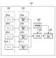
図1は、視体積交差法の基本原理を示す図である。図1(a)は、ある対象物体(オブジェクト)Cを撮像装置であるカメラにより撮像したときの図である。図1(a)における、カメラが撮像した撮像画像の撮像面Sオブジェクトを示す前景の二次元シルエットDaが得られる。図1(b)は、カメラの投影中心(Pa)から前景領域Daの輪郭上の各点を通すように、三次元空間中に広がる錐体を示す図である。この錐体のことを当該カメラによる視体積Vaと呼ぶ。 FIG. 1 is a diagram showing the basic principle of the visual volume intersection method. FIG. 1(a) is a diagram when a certain target object (object) C is imaged by a camera, which is an imaging device. A foreground two-dimensional silhouette Da representing the imaging surface S object of the captured image captured by the camera in FIG. 1A is obtained. FIG. 1(b) is a diagram showing a cone extending in a three-dimensional space from the projection center (Pa) of the camera through each point on the contour of the foreground area Da. This cone is called a visual volume Va by the camera.
図1(c)ではこの複数の視体積によりオブジェクトの三次元(前景の三次元モデル)が求まる様子を示す図である。図1(c)のように、位置が異なる複数の異なるカメラによって同期撮像された画像に基づく前景領域(オブジェクト領域)からカメラごとの複数の視体積を求める。視体積交差法は、この複数のカメラの視体積の交差(共通領域)を求めることによって、オブジェクトの前景の三次元モデルを求める方法である。 FIG. 1(c) shows how a three-dimensional object (a three-dimensional model of the foreground) is obtained from the plurality of visual volumes. As shown in FIG. 1C, a plurality of visual volumes are obtained for each camera from a foreground region (object region) based on images synchronously captured by a plurality of different cameras at different positions. The visual volume intersection method is a method of obtaining a three-dimensional model of the foreground of an object by obtaining the intersection (common area) of the visual volumes of the plurality of cameras.
ここで、画像の「前景」となるオブジェクトは仮想視点で任意の角度から見ることを可能とする対象物体である。本実施形態では競技場のフィールド上に存在する人物のことを指す。または、前景となりうるオブジェクトは、ボール、またはゴール等、画像パターンが予め定められている物体であってもよい。また、オブジェクトは動体であってもよいし、静止体であってもよい。「背景」は画像の前景以外の領域を指す。 Here, the "foreground" object of the image is a target object that can be viewed from any angle with a virtual viewpoint. In this embodiment, it refers to a person existing on the field of the stadium. Alternatively, the object that can be the foreground may be an object with a predetermined image pattern, such as a ball or a goal. Also, the object may be a moving body or a stationary body. "Background" refers to areas of an image other than the foreground.
前景の三次元モデルを用いて生成される仮想視点画像とは、実カメラとは異なる仮想カメラの位置及び向き等に基づいて生成される画像であり、自由視点画像や任意視点画像とも呼ばれる。例えば、仮想視点画像を生成する技術によれば、サッカーやバスケットボールのハイライトシーンを様々な角度から視聴することが出来るため、通常の画像と比較してユーザに高臨場感を与えることが出来る。視体積交差法に基づく仮想視点画像生成システムも数多く開発されており、このようなシステムにおいては適切に前景の三次元モデルを生成することが求められている。 A virtual viewpoint image generated using a three-dimensional model of the foreground is an image generated based on the position and orientation of a virtual camera different from that of a real camera, and is also called a free viewpoint image or an arbitrary viewpoint image. For example, according to the technology for generating a virtual viewpoint image, it is possible to view the highlight scenes of soccer or basketball from various angles, so that it is possible to give the user a high sense of realism compared to ordinary images. Many virtual viewpoint image generation systems based on the visual volume intersection method have also been developed, and such systems are required to appropriately generate a three-dimensional model of the foreground.
図2は、視体積交差法による前景の三次元モデルを生成するために、前景となる対象物体(オブジェクト)をカメラA~Cにおいて撮像したときの図である。このとき、カメラBによる撮像がカメラの故障等により失敗し、カメラBによる撮像面から得られた前景領域200は、前景を示す領域がほとんどない画像となっている。このようなカメラの故障のほか、カメラと画像データを取得する画像処理装置とをつなぐ伝送系の異常、または不適切な撮像パラメータの設定等のため、前景領域がオブジェクトのシルエットを正しく表現しないことがある。この正常では無い状態を「不正」な状態と呼ぶ。図2の例では、カメラBの視体積と、カメラB以外による正常なカメラA、Cによる視体積と、の視体積の共通領域は無くなり、前景の三次元モデルが適切に生成されないことになる。 2A to 2C are diagrams of a foreground target object captured by cameras A to C in order to generate a three-dimensional model of the foreground by the visual volume intersection method. At this time, the image pickup by the camera B fails due to camera failure or the like, and the
このため、本実施形態は後述するように、前景領域を示す画像(前景マスク画像)が不正である場合、その不正な前景マスク画像が前景の三次元モデルの生成に与える悪影響を抑制させるための処理を行う形態である。 For this reason, as will be described later, in the present embodiment, when an image representing a foreground region (foreground mask image) is invalid, a method for suppressing the adverse effect of the invalid foreground mask image on the generation of the foreground 3D model is provided. It is a form of processing.
[システム構成]
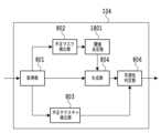
図3は、本実施形態に係る仮想視点画像生成システムの構成の一例を示すブロック図である。仮想視点画像生成システム100は、複数のカメラ101a~101rからなるカメラアレイ101、複数の前景抽出装置102a~102rで構成される前景抽出装置群102、制御装置103、生成装置104、レンダリング装置105を有する。前景抽出装置102a~102r、制御装置103、生成装置104及びレンダリング装置105は、演算処理を行うCPU、演算処理の結果やプログラム等を記憶するメモリなどを備えた一般的な画像処理装置によって実現される。前景抽出装置102a~102r、制御装置103、生成装置104及びレンダリング装置105は、CPUとは異なる専用の1又は複数のハードウェアあるいはGPU(Graphics Processing Unit)を有していてもよい。そして、CPUによる処理の少なくとも一部をGPUあるいは専用のハードウェアが行うようにしても良い。専用のハードウェアの例としては、ASIC(特定用途向け集積回路)、及びDSP(デジタルシグナルプロセッサ)等がある。[System configuration]
FIG. 3 is a block diagram showing an example of the configuration of the virtual viewpoint image generation system according to this embodiment. A virtual viewpoint
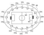
カメラアレイ101は、複数のカメラ101a~101rで構成され、様々な角度の複数方向から前景となるオブジェクトを撮像して前景抽出装置群102へ撮像画像の画像データを出力する。図4は、カメラアレイ101を構成する全16台のカメラ101a~101rの配置を、フィールド400を真上から見た俯瞰図において示した図である。図4に示すようにカメラは競技場402の周囲に配置され、全てのカメラ101a~101rで共通したフィールド上の注視点401に向けて様々な角度から時刻同期して撮像する。 The
前景抽出装置群102は、夫々のカメラ101a~101rに対応する前景抽出装置102a~102rを有している。各前景抽出装置102a~102rは、対応するカメラから出力された撮像画像の画像データから撮像画像に含まれる前景を示す前景領域(オブジェクト領域)を抽出する。そして各前景抽出装置102a~102rは、対応するカメラごとに、撮像画像の前景領域とそれ以外の領域とを示す前景マスク画像、および前景のテクスチャを示す画像である前景テクスチャ画像を生成する。 The
ここで、図を用いて撮像画像と前景マスク画像と前景テクスチャ画像との説明をする。図5は、カメラアレイ101に属するカメラの1つである図4のカメラ101mによってフィールド400の注視点401を撮像した撮像画像500を示す図である。撮像画像500には5つの前景5a~5eが含まれる。図6は、図5の撮像画像500の前景が前景領域として示された前景マスク画像600の例である。図6の前景マスク画像600のように、前景マスク画像は2値画像で表される。本実施形態では、前景マスク画像は、前景の領域を示す前景領域を白色で表し、前景領域以外の領域を黒で表した2値画像であるものとして説明する。前景マスク画像は後述する前景の三次元モデルの生成において利用される。 Here, the captured image, the foreground mask image, and the foreground texture image will be described with reference to the drawings. FIG. 5 is a diagram showing a captured
また、前景抽出装置102a~102rは、対応するカメラによって撮像された撮像画像から前景を内包する矩形領域を算出する。図7(a)は、前景抽出装置102mが図5の撮像画像500から前景を検出し、前景を含む領域を矩形領域として検出したときの図である。図5の撮像画像500では前景は5つあるため図7(a)では5つの矩形領域が検出されていることを示している。 Also, the
図6および図7(a)のように撮像画像から前景を検出する方法は限定しない。例えば、予め保持している撮像画像に対応する背景画像と、撮像画像との画素値を比較し、画素値に基づく値の差分が閾値を超えた画素によって構成される領域を前景領域と判定する方法を用いればよい。 The method of detecting the foreground from the captured image as shown in FIGS. 6 and 7A is not limited. For example, the background image corresponding to the captured image held in advance is compared with the pixel values of the captured image, and a region composed of pixels whose difference in value based on the pixel value exceeds a threshold value is determined as the foreground region. method should be used.
図7(b)は、図7(a)で算出された矩形領域を切り出した夫々の矩形画像を表している。この矩形画像を前景テクスチャ画像7a~7eと呼ぶ。前景テクスチャ画像7a~7eは前景の三次元モデルに色付けを行う際に利用される。 FIG. 7(b) shows respective rectangular images cut out from the rectangular regions calculated in FIG. 7(a). These rectangular images are called
制御装置103は、カメラアレイ101のカメラによって時刻同期され撮像された撮像画像の画像データからカメラ101a~カメラ101rの位置や姿勢を示すカメラパラメータを算出し、生成装置104とレンダリング装置105に出力する。 The
カメラパラメータは、外部パラメータ、および内部パラメータで構成されている。外部パラメータは、回転行列および並進行列で構成されておりカメラの位置や姿勢を示すものである。一方、内部パラメータは、カメラの焦点距離や光学的中心などを含みカメラの画角や撮像センサの大きさなどを示すものである。カメラパラメータを算出する処理はキャリブレーションと呼ばれ、チェッカーボードのような特定パターンを撮像した複数枚の画像を用いて取得した三次元の世界座標系の点とそれに対応する二次元上の点との対応関係を用いることで求められる。 Camera parameters consist of external parameters and internal parameters. The extrinsic parameters consist of a rotation matrix and a translation matrix, and represent the position and orientation of the camera. On the other hand, the internal parameters include the focal length and optical center of the camera, and indicate the angle of view of the camera, the size of the imaging sensor, and the like. The process of calculating the camera parameters is called calibration, and the points in the three-dimensional world coordinate system obtained using multiple images of a specific pattern such as a checkerboard and the corresponding two-dimensional points It is obtained by using the correspondence of
生成装置104は、制御装置103よりカメラパラメータを取得し、前景抽出装置群102から前景マスク画像と前景テクスチャ画像を取得する。そして生成装置104は取得した前景マスク画像から前景の三次元モデルを生成する。生成装置104は、生成した前景の三次元モデルのデータをレンダリング装置105に出力する。生成装置104が行う処理の詳細については後述する。 The
レンダリング装置105は、生成装置104から前景の三次元モデル、前景テクスチャ画像、および後述する可視性判定結果を取得する。また、制御装置103からカメラパラメータを取得する。レンダリング装置105はこれらのデータに基づき仮想視点画像を生成する。具体的には、カメラパラメータから前景テクスチャ画像と前景の三次元モデルとの位置関係を求め、三次元モデルを構成する各ボクセルに、前景テクスチャ画像の画素の色を基に色づけする。ボクセルの説明については後述する。仮想視点画像は、動画であっても、静止画であってもよい。 The
なお、本実施形態では前景抽出装置102a~102rと生成装置104がスター型のトポロジーで接続されている形態であるが、ディジーチェーン接続によるリング型またはバス型等のトポロジーで接続されている形態であってもよい。 In this embodiment, the
[生成装置の機能構成]
図8は、本実施形態における生成装置104の機能構成を示すブロック図である。生成装置104は、取得部801、不正マスク検出部802、処理部803、生成部804、不正テクスチャ検出部805、および可視性判定部806を有する。[Functional Configuration of Generation Device]
FIG. 8 is a block diagram showing the functional configuration of the
取得部801は、前景抽出装置102a~102rから各カメラ101a~101rの撮像画像に基づく前景マスク画像、および前景テクスチャ画像等を取得する。不正マスク検出部802は、取得部801が取得した前景マスク画像から正常ではない「不正」な前景マスク画像を検出する。 The
処理部803は、不正な前景マスク画像が前景の三次元モデルの生成に与える影響を抑制させるための処理をする。処理の説明は後述する。 A
生成部804は、カメラアレイ101のカメラが撮像した撮像画像に基づく複数の前景マスク画像と、カメラアレイ101の位置や姿勢を示すカメラパラメータから視体積交差法により前景の三次元モデルを生成し、可視性判定部806へ出力する。 A
不正テクスチャ検出部805は、取得部801が取得した前景テクスチャ画像から不正な前景テクスチャ画像を検出する。可視性判定部806は、前景の三次元モデルを構成する各ボクセルがカメラアレイ101を構成する各カメラの画角内であるかを判定する。可視性判定部806による判定結果は、レンダリング装置105において前景の三次元モデルを構成する各ボクセルに色づけする際に利用される。 An unauthorized
[処理部による処理の説明]
実施形態1では、処理部803は、不正な前景マスク画像が前景の三次元モデルの生成に与える影響を抑制させるための処理として、不正な前景マスク画像を、全ての領域が前景領域である画像に置き換える処理が行われる。本実施形態では、前景領域を示す色は白であることから、不正な前景マスク画像を全ての領域が白の画像(全白画像)に置き換える処理を行う。[Description of Processing by Processing Unit]
In the first embodiment, the
ここで、本実施形態における処理部803の処理について図を用いて説明する。図9(a)は不正な前景マスク画像の一例を示す図である。カメラの画角内には前景となるオブジェクトが含まれているものの、当該カメラの故障等によりカメラの撮像画像から前景領域が正しく抽出されないことがある。このため図9(a)のように前景領域を示す白色の領域がほとんど含まれない不正な前景マスク画像が取得されることがある。 Here, the processing of the
前述のとおり、前景の三次元モデルは、複数視点の前景領域から得られる夫々の視体積の共通領域から生成される。即ち、基本的に、前景となるオブジェクトを撮像する位置にある全てのカメラによる視体積が交差する共通領域に基づき前景の三次元モデルが生成される。しかし、図9(a)のように不正な前景マスク画像には正常な前景マスク画像に比べ前景領域がほとんど含まれない。このため不正な前景マスク画像に対応する視体積は、正常なマスク画像に対応する視体積に比べほとんど無い状態となるから、不正な前景マスク画像に対応する視体積は他のカメラによる視体積と交差しない。よって全てのカメラの視体積が交差する共通領域が無くなるため前景の三次元モデルの生成が正常に行われない虞がある。 As described above, a 3D model of the foreground is generated from the common region of each view volume obtained from the foreground regions of multiple viewpoints. That is, basically, a three-dimensional model of the foreground is generated based on the common area where the visual volumes of all the cameras positioned to image the foreground object intersect. However, as shown in FIG. 9(a), the incorrect foreground mask image contains almost no foreground area compared to the normal foreground mask image. As a result, the visual volume corresponding to the incorrect foreground mask image is almost zero compared to the visual volume corresponding to the normal mask image. do not cross. Therefore, since there is no common area where the visual volumes of all cameras intersect, there is a possibility that the three-dimensional model of the foreground will not be generated normally.
図9(b)は図9(a)の不正な前景マスク画像に対して処理部803が処理を行ったことにより不正な前景マスク画像が、全白画像に置き換えられたことを示す図である。また図9(c)は不正な前景マスク画像が全白画像と置き換えられたことにより、全白画像に置き換えられた前景マスク画像による視体積と、それ以外の正常な前景マスク画像による前景の三次元モデルの生成の様子を示している。前景領域は白色の領域であることから、全白画像となった前景マスク画像の全ての領域が前景領域となる。このため全白画像の前景領域を通る視体積は最大となる。よって他の正常な前景マスク画像による視体積(図9(c)のカメラAおよびカメラCの視体積)の共通領域と、全白画像となった前景マスク画像による視体積(図9(c)カメラBの視体積)は交差する。このため、不正な前景マスク画像の影響により前景の三次元モデルが不必要に削られることを抑制することができる。つまり、正常な前景マスク画像による視体積の共通領域のみによって前景の三次元モデルを生成するのと同じ効果を生じさせることができる。 FIG. 9B is a diagram showing that the
本実施形態では、不正な前景マスク画像が全白画像に置き換えられる処理がされるものとして説明するが、不正な前景マスク画像から置き換えられる画像の白の領域は全ての領域でなくてもよい。処理部803によって置き換えられた画像の前景領域を通る視体積が、他のカメラの視体積と交差するのに十分な大きさであればよい。 In the present embodiment, a process is described in which an incorrect foreground mask image is replaced with an all-white image. It is only necessary that the viewing volume passing through the foreground region of the image replaced by processing
このように、不正な前景マスク画像を全白画像に置き換えることにより、後続の処理である前景の三次元モデルを生成する処理において、不正な前景マスク画像を除外する設定が不要となり前景の三次元モデルを生成する処理の継続が容易となる。 In this way, by replacing the invalid foreground mask image with the all-white image, in the subsequent process of generating the 3D model of the foreground, the setting for excluding the invalid foreground mask image becomes unnecessary. It becomes easier to continue the process of generating the model.
なお、他の形態として、前景領域を示す領域が黒であり、前景領域以外の領域を白で示す前景マスク画像が生成される形態が考えられる。このような形態においては、処理部803は不正な前景マスク画像の全領域に対して前景領域を示す色である黒にする処理が行われることになる。いずれにしても処理部803は、不正な前景マスク画像を全ての領域が前景領域である画像に置き換えるように処理をする。 As another form, a form is conceivable in which a foreground mask image is generated in which the area indicating the foreground area is black and the area other than the foreground area is white. In such a form, the
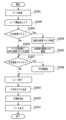
[フローチャート]
図10は、生成装置104における前景の三次元モデルを生成する処理のフローチャートの一例を示す図である。図10のフローチャートで示される一連の処理は、生成装置104のCPU(不図示)がROM(不図示)に記憶されているプログラムコードをRAM(不図示)に展開し実行することにより行われる。なお、各処理の説明における記号「S」は、当該フローチャートにおけるステップであることを意味する。図10を用いて前景の三次元モデルを生成する一連の処理を説明する。[flowchart]
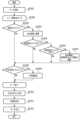
FIG. 10 is a diagram showing an example of a flowchart of processing for generating a three-dimensional model of the foreground in the
S1001において取得部801は、前景抽出装置群102よりカメラアレイ101の各カメラで同期撮像された撮像画像に基づき生成された前景マスク画像、および前景テクスチャ画像を取得する。また制御装置103からカメラアレイ101を構成する各カメラのカメラパラメータを取得する。 In S<b>1001 , the
ここからは、カメラアレイ101を構成するカメラ101a~101rのうち処理対象のカメラに基づく全ての前景マスク画像および全ての前景テクスチャ画像について、S1003~S1006を繰り返す。 From here on, S1003 to S1006 are repeated for all foreground mask images and all foreground texture images based on the cameras to be processed among the
即ち、S1002においてカメラアレイを構成する未処理のカメラの中から処理対象のカメラが選択され、S1003~S1006の処理が処理対象のカメラに対する前景マスク画像および前景テクスチャ画像について行われる。処理対象のカメラに対する処理が終了すると、再度、未処理のカメラの中から処理対象のカメラが選択される。未処理のカメラがなくなったら、S1007に進む。 That is, in S1002, a camera to be processed is selected from the unprocessed cameras forming the camera array, and the processes of S1003 to S1006 are performed on the foreground mask image and the foreground texture image of the camera to be processed. When the processing for the camera to be processed is completed, the camera to be processed is selected again from among the unprocessed cameras. When there are no more unprocessed cameras, the process advances to S1007.
S1003において不正マスク検出部802は、処理対象のカメラの前景マスク画像が不正であるかを検出する。前景マスク画像の画像データは、基になった撮像画像の情報等が付加されたデータヘッダを有している。不正マスク検出部802による前景マスク画像が不正かを検出する方法として、前景マスク画像のデータヘッダに含まれる情報と画像が整合していない、またはデータヘッダの情報に異常値がある場合には不正と検出する。例えば、不正マスク検出部802は、データヘッダに含まるべき情報が含まれていない、または前景マスク画像のデータヘッダに記憶されている前景の数と取得した前景マスク画像の前景領域の数が一致していない場合は不正な画像として検出する。 In S1003, the unauthorized
不正マスク検出部802が不正かを検出する手段にはこれに限られない。他にも、前景マスク画像のデータサイズが正常でない場合は不正な前景マスク画像であると検出する方法でもよい。または、不正マスク検出部802は、処理対象のカメラの撮像画像と、他のカメラによる撮像画像との前景の画素値を比較して差分が閾値以上ある場合、処理対象のカメラによる前景マスク画像は不正な画像と検出する方法でもよい。または、前景マスク画像の画像データの整合性を示すチェックサムが正しくない場合、不正と検出する方法でもよい。あるいは、取得部801が前景抽出装置群102から前景マスク画像の画像データを取得できなかったときも、不正マスク検出部802は処理対象のカメラによる前景マスク画像が不正な前景マスク画像であるものとして検出する方法でもよい。 The means by which the fraud
不正な前景マスク画像として検出された場合(S1003:YES)、S1004において処理部803は、不正な前景マスク画像を全白画像に置き換える処理をする。そして、全白画像を処理対象のカメラの前景マスク画像として生成部804に出力する。S1004の処理が終了した場合、または前景マスク画像が不正として検出されなかった場合(S1003:NO)、S1005の処理に進む。 If an illegal foreground mask image is detected (S1003: YES), the
S1005において不正テクスチャ検出部805は、処理対象のカメラの前景テクスチャ画像から不正な画像を検出する。不正テクスチャ検出部805が不正かを検出する手段として、S1003において不正マスク検出部802が不正な前景マスク画像を検出する方法と同様の方法を用いればよい。例えば、取得した前景テクスチャ画像の画像データに含まれるデータヘッダに含まれる情報と画像が整合していない、またはデータヘッダの情報に異常値がある場合は不正な画像として検出する。 In S1005, the unauthorized
前景テクスチャ画像が不正な画像として検出された場合(S1005:YES)、S1006において可視性判定部806は、処理対象のカメラの情報を取得する。そして可視性判定部806は、処理対象のカメラに基づく前景テクスチャ画像の「可視性」を不可視として設定する。可視性が不可視と設定されることにより、レンダリング装置105において本フローチャートの終了後に行われる前景の三次元モデルに色づけを行う際に、不正な前景テクスチャ画像に基づき色づけが行われることを防ぐことができる。全てのカメラに対して処理が終了した場合、または前景テクスチャ画像が不正と検出されなかった場合(S1005:NO)はS1007に進む。 If the foreground texture image is detected as an invalid image (S1005: YES), in S1006 the
なお、本実施形態では、前景マスク画像と前景テクスチャ画像の両方の画像について不正な画像であるかの検出が行われる形態である。他にも、前景マスク画像と前景テクスチャ画像のどちらか一方の画像のみ不正であるかが検出され、不正と検出された場合は、もう一方の画像も自動的に不正な画像であるものとして後続の処理が行われる形態であってもよい。例えば、S1005における処理は行われず、S1003において不正マスク検出部802は処理対象のカメラによる前景マスク画像が不正な画像かの検出のみ行う。不正マスク検出部802が、前景マスク画像を不正と検出した場合、処理対象のカメラの前景テクスチャ画像についても不正な画像であるものとしてS1006の処理が行われる形態でもよい。 In this embodiment, it is determined whether or not both the foreground mask image and the foreground texture image are invalid images. In addition, it detects whether only one of the foreground mask image and the foreground texture image is invalid, and if it is detected as invalid, the other image is automatically regarded as an invalid image. may be performed. For example, the processing in S1005 is not performed, and in S1003 the unauthorized
S1007において生成部804は、各カメラによる正常な前景マスク画像と処理部803によって処理された画像を基に前景の三次元モデルを生成する。本実施形態では三次元空間を構成する要素としてボクセルを用いて以下のような手順で行う。 In S<b>1007 , the
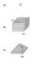
図11はボクセルを説明するための図である。ボクセルとは、図11(a)で示すような微小な立方体のことである。図11(b)は前景の三次元モデルを生成するカメラの対象空間をボクセルの集合として表したものである。 FIG. 11 is a diagram for explaining voxels. A voxel is a minute cube as shown in FIG. 11(a). FIG. 11(b) represents the object space of the camera that generates the three-dimensional model of the foreground as a set of voxels.
対象空間のボクセルのうち処理対象のボクセルである1つの着目ボクセルを各カメラの前景マスク画像に射影したとき、各カメラの前景マスク画像の前景領域内に着目ボクセルの射影が収まるか否かが判定される。この判定の結果、各カメラの前景マスク画像のうち、着目ボクセルの射影が前景領域から外れる前景マスク画像が1つでも存在する場合、着目ボクセルは削除される。 When one voxel of interest, which is the voxel to be processed among the voxels in the object space, is projected onto the foreground mask image of each camera, it is determined whether or not the projection of the voxel of interest fits within the foreground area of the foreground mask image of each camera. be done. As a result of this determination, if there is even one foreground mask image in which the projection of the voxel of interest deviates from the foreground region among the foreground mask images of each camera, the voxel of interest is deleted.
一方、対象空間を撮像する全てのカメラによる前景マスク画像の前景領域の内部に着目ボクセルの射影が収まる場合、その着目ボクセルは前景を構成するボクセルと判定され着目ボクセルは残される。生成部804は、この一連の処理を対象空間の全てのボクセルに対して行うことにより、前景の三次元モデルを形成する。 On the other hand, if the projection of the voxel of interest falls within the foreground area of the foreground mask image captured by all the cameras that capture the target space, the voxel of interest is determined to constitute the foreground, and the voxel of interest is left. The generating
図11(c)は図11(b)から、いずれのカメラの前景領域にも収まらなかったボクセルを削ることで、前景の形状が四角錐である三次元モデルがボクセルによって生成されたことを表している図である。例えば図11(b)の図におけるボクセル1101を着目ボクセルとしたとき、ボクセル1101の射影が前景領域から外れる前景マスク画像があったことからボクセル1101は削除されている。一方、図11(b)の図におけるボクセル1102を着目ボクセルとしたとき、ボクセル1102は対象空間を撮像する全てのカメラの前景マスク画像の前景領域の内部にボクセル1102の射影が収まることからボクセル1102は残されている。こうして図11(c)の前景の三次元モデルが生成されている。 FIG. 11(c) shows that a three-dimensional model with a quadrangular pyramid foreground is generated by removing voxels that did not fit in the foreground area of any camera from FIG. 11(b). is a diagram. For example, when the
なお、本実施形態は前景の三次元モデルを立方体のボクセルとして表すがこれに限られない。他にも例えば、三次元空間を構成する要素として点を用いて、前景の三次元モデルを点群で表してもよい。 In this embodiment, the three-dimensional model of the foreground is expressed as cubic voxels, but the present invention is not limited to this. Alternatively, for example, a point group may be used to represent a three-dimensional model of the foreground using points as elements constituting a three-dimensional space.
S1008において可視性判定部806は、生成された前景の三次元モデルに対して前景の三次元モデルの表面上の各ボクセルの面がどのカメラから見えるかの判定をする「可視性判定」を行う。S1006において不正テクスチャ検出部805によって検出された不正な前景テクスチャ画像は、不可視として設定されている。前景テクスチャ画像が不可視と設定されると、可視性判定部806は、前景テクスチャ画像の基となった撮像画像を撮像したカメラの画角内にボクセルが含まれる場合であっても、当該ボクセルが見えるカメラとして判定しない。そして可視性判定部806による判定結果は、S1009においてレンダリング装置105に出力される。 In S1008, the
この後の仮想視点画像を生成する処理として、レンダリング装置105では、可視性判定においてボクセルの面が見えると判定されたカメラの前景テクスチャ画像を用いて、当該ボクセルの面の色を決定する。このため、可視性判定部806が不正な前景テクスチャ画像を不可視と設定することにより、レンダリング装置105が不正な前景テクスチャ画像を用いて色づけすることを防ぐことができる。 As a subsequent process for generating a virtual viewpoint image, the
S1009において可視性判定部806は、レンダリング装置105へ前景の三次元モデル、前景テクスチャ画像、可視性判定結果を出力する。 In S<b>1009 , the
以上が、本実施形態に係る前景の三次元モデル生成の処理の内容である。動画の仮想視点画像を生成する場合には、上述の各ステップの処理をフレーム単位で繰り返し行い、フレーム毎に前景の三次元モデルが生成される。その後の処理としてレンダリング装置105において仮想視点画像が生成される。 The above is the content of the foreground 3D model generation processing according to the present embodiment. When generating a virtual viewpoint image of a moving image, the processing of each step described above is repeated for each frame, and a three-dimensional model of the foreground is generated for each frame. As subsequent processing, the
以上説明したように本実施形態によれば、不正な前景マスク画像を全白画像とすることにより、不正な前景マスク画像によって生成される前景の三次元モデルの欠落を抑制することができる。よって、不正な前景マスク画像による影響を取り除いた前景の三次元モデルの生成が可能となる。また、不正な前景テクスチャ画像を不可視として設定することにより、不正な前景テクスチャ画像によって前景の三次元モデルに色付がされることを防ぐことができる。このため画質劣化を抑えた仮想視点画像の生成をすることができる。 As described above, according to the present embodiment, by using an all-white image as an incorrect foreground mask image, it is possible to suppress the omission of the three-dimensional model of the foreground generated by the incorrect foreground mask image. Therefore, it is possible to generate a three-dimensional model of the foreground from which the influence of the incorrect foreground mask image is removed. Also, by setting the illegal foreground texture image as invisible, it is possible to prevent the foreground 3D model from being colored by the illegal foreground texture image. Therefore, it is possible to generate a virtual viewpoint image in which image quality deterioration is suppressed.
<実施形態2>
実施形態1では、不正な前景マスク画像については全白画像になるように処理されるため、不正な前景マスク画像の一部に正常な前景領域が含まれている場合であっても、正常な前景領域は前景の三次元モデルの生成に用いられなかった。例えば、実施形態1では全てのカメラの前景マスク画像が不正である場合、ボクセル集合は削られずに前景の三次元モデルが生成されることになる。本実施形態は、前景マスク画像のうち、それぞれの前景領域ごとに生成される前景矩形マスク画像を用いて、当該前景矩形マスク画像ごとに不正な画像があるかの検出を行う形態である。<Embodiment 2>
In the first embodiment, the illegal foreground mask image is processed so as to become an all-white image. The foreground region was not used to generate the 3D model of the foreground. For example, in the first embodiment, if the foreground mask images of all cameras are invalid, a 3D model of the foreground is generated without removing the voxel set. In this embodiment, among the foreground mask images, a foreground rectangular mask image generated for each foreground region is used to detect whether or not each foreground rectangular mask image contains an invalid image.
このため、本実施形態では、前景マスク画像のうち、一部に正常な前景領域が含まれている場合、正常な前景領域については前景の三次元モデル生成に寄与させることができる。本実施形態については、実施形態1からの差分を中心に説明する。特に明記しない部分については実施形態1と同じ構成および処理である。 Therefore, in the present embodiment, when a normal foreground region is partially included in the foreground mask image, the normal foreground region can contribute to the generation of the foreground 3D model. This embodiment will be described with a focus on differences from the first embodiment. Parts not specified are the same in configuration and processing as in the first embodiment.
本実施形態における前景抽出装置群102における各前景抽出装置102a~102rの処理について図を用いて説明する。図12は、図7(b)で示した前景テクスチャ画像7a~7eから前景の領域を抽出し、前景領域を白で表し前景以外の領域を黒で表した2値の画像である。この前景ごとの2値の画像を前景矩形マスク画像12a~12eとよぶ。各カメラ101a~101rに応じた前景抽出装置102a~102rは、実施形態1で説明した前景マスク画像、前景テクスチャ画像に加えて、この前景矩形マスク画像を生成する。そして前景抽出装置102a~102rは、前景矩形マスク画像の前景マスク画像上の座標を算出して、それぞれのデータを生成装置104に送信する。 The processing of each
前景抽出装置102a~102rは、図6の前景マスク画像600を生成するにあたり複数の前景矩形マスク画像12a~12eを対応する座標へ貼り付けることにより合成して前景マスク画像を生成してもよい。 The
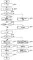
[フローチャート]
図13は、本実施形態の生成装置104で行われる三次元モデルを生成する処理を説明するためのフローチャートの一例を示す図である。[flowchart]
FIG. 13 is a diagram showing an example of a flowchart for explaining the process of generating a three-dimensional model performed by the generating
S1301において取得部801は、前景抽出装置102a~102rから各カメラ101a~101rに応じた前景マスク画像、前景テクスチャ画像、前景矩形マスク画像、および前景矩形マスク画像の前景マスク画像上の座標を取得する。 In S1301, the
S1302~S1304の処理はS1002~S1004の処理と同一であるため説明を省略する。 Since the processing of S1302 to S1304 is the same as the processing of S1002 to S1004, the description is omitted.
処理対象のカメラの前景マスク画像が不正であった場合、S1305において不正マスク検出部802は、処理対象のカメラが撮像した撮像画像に基づく前景矩形マスク画像を取得したかを判定する。前景マスク画像が不正として検出された場合であっても、前景矩形マスク画像は送信されることがあるためである。 If the foreground mask image of the camera to be processed is invalid, in S1305 the invalid
前景矩形マスク画像を取得していると判定した場合(S1305:YES)、S1306において不正マスク検出部802は、前景ごとの前景矩形マスク画像が正常かを判定する。前景矩形マスク画像から正常な(不正ではない)画像を検出する方法は、S1303における不正な前景マスク画像を検出する方法と同様の方法を用いればよい。例えば、夫々の前景矩形マスク画像の画像データに含まれるデータヘッダの情報と画像が整合していない、またはデータヘッダの情報に異常値がある場合には不正と検出する。不正と検出されなかった場合は正常な画像とする方法を用いればよい。 If it is determined that the foreground rectangular mask image has been acquired (S1305: YES), in S1306 the unauthorized
不正ではない正常な前景矩形マスク画像がある場合(S1306:YES)、S1307において処理部803は、S1304において全白画像とした前景マスク画像上に、正常な前景矩形マスク画像を重畳する処理をする。その結果得られた画像を処理対象のカメラの前景マスク画像として生成部804に出力する。正常な前景矩形マスク画像が複数ある場合は、複数の正常な前景矩形マスク画像を全白画像上の重畳する処理をする。処理部803は、前景矩形マスク画像を重畳した画像を処理対象のカメラの前景マスク画像に置き換えて生成部804に出力する。 If there is a normal foreground rectangular mask image that is not fraudulent (S1306: YES), in S1307 the
図14(a)は、正常な前景マスク画像であれば、図6の前景マスク画像600のように5つの前景領域が含まれる画像ではあるが、3つの前景領域しか含まれていない不正な前景マスク画像を示す図である。図14(a)の不正な前景マスク画像から前景の三次元モデルを生成すると、前景領域として認識されなかった前景の三次元モデルは、削られて劣化したものとなる。一方、実施形態1のように図14(a)の不正な前景マスク画像を全白画像に置き換えると、正常に前景のシルエットを表している前景領域についても、前景の三次元モデルの生成に用いられないことになる。 FIG. 14A shows an image containing five foreground areas like the
図14(b)は図14(a)の不正な前景マスク画像に含まれる正常な前景矩形マスク画像の例である。図14(c)は、全白画像に、正常な前景矩形マスク画像を重畳する処理がされた前景マスク画像である。この前景マスク画像が前景の三次元モデルの生成に用いられることにより、正常な前景矩形マスク画像については前景の三次元モデルに寄与させることができる。また、正常に前景領域が抽出できなかった前景の三次元モデルの生成においては、不正な前景マスク画像により三次元モデルが削られずに三次元モデルを生成させることができる。 FIG. 14(b) is an example of a normal foreground rectangular mask image included in the incorrect foreground mask image of FIG. 14(a). FIG. 14(c) is a foreground mask image obtained by superimposing a normal foreground rectangular mask image on an all-white image. By using this foreground mask image to generate the foreground three-dimensional model, the normal foreground rectangular mask image can contribute to the foreground three-dimensional model. Also, in the generation of a three-dimensional model of the foreground for which the foreground region could not be extracted normally, the three-dimensional model can be generated without the three-dimensional model being deleted by an incorrect foreground mask image.
なお、図14(c)のような前景マスク画像を生成する方法として全白画像に正常な前景矩形マスク画像を重畳させる方法を説明したが。他にも、処理部803は、不正な前景マスク画像から正常な前景領域を含む矩形の領域を検出し、不正な前景マスク画像に含まれる正常な前景領域を含む矩形の領域以外の領域を白の領域として処理した画像を前景マスク画像とする方法を用いてもよい。 As a method of generating a foreground mask image such as that shown in FIG. 14C, a method of superimposing a normal foreground rectangular mask image on an all-white image has been described. In addition, the
前景矩形マスク画像が取得できなかった場合(S1305:NO)、正常な前景矩形マスク画像が無かった場合(S1306:NO)、処理部803は、不正な前景マスク画像を全白画像に置き換える。処理部803は、置き換えた全白画像を処理対象のカメラの前景マスク画像として生成部804に出力する。 If the foreground rectangular mask image could not be obtained (S1305: NO) or if there was no normal foreground rectangular mask image (S1306: NO), the
S1308において不正テクスチャ検出部805は、処理対象のカメラの前景テクスチャ画像から不正な画像を検出する。不正テクスチャ検出部805が不正かを検出する手段として、S10005で説明した方法に加えて、S1306において不正と検出された前景矩形マスク画像については、対応する前景テクスチャ画像についても不正なものとして検出する方法を用いてもよい。S1309~S1312の処理は、S1006~S1009の処理と同一であるため説明は省略する。 In S1308, the unauthorized
以上説明したように本実施形態によれば、不正な前景マスク画像であっても、正常に前景の領域を示している領域については、当該前景の三次元モデルの生成に寄与させることができる。即ち、本実施形態は、不正な前景マスク画像のうち、正常な前景領域以外の領域に対しては三次元モデル生成に与える影響を抑制するための処理が行われることになる。このように処理されることにより、不正な前景マスク画像による前景の三次元モデル生成への影響を少なくし、画質劣化を抑えた仮想視点画像の生成を実現することができる。 As described above, according to the present embodiment, even an incorrect foreground mask image can contribute to the generation of a three-dimensional model of the foreground for an area that normally represents the foreground area. That is, in the present embodiment, processing for suppressing the influence on 3D model generation is performed on regions other than the normal foreground region in the incorrect foreground mask image. By performing such processing, it is possible to reduce the influence of an incorrect foreground mask image on the generation of a three-dimensional model of the foreground, and to realize generation of a virtual viewpoint image with suppressed image quality deterioration.
<実施形態3>
本実施形態では、取得した前景マスク画像が不正として検出された場合、直前の正常な前景マスク画像の前景領域を広げる処理を行う。当該広げる処理がされた画像を不正な前景マスク画像と置き換えることにより、不正な前景マスク画像による前景の三次元モデルの品質劣化を抑制する形態である。本実施形態については、実施形態1からの差分を中心に説明する。特に明記しない部分については実施形態1と同じ構成および処理である。<Embodiment 3>
In the present embodiment, when the acquired foreground mask image is detected to be invalid, processing is performed to widen the foreground region of the previous normal foreground mask image. By replacing the widened image with an incorrect foreground mask image, it is possible to suppress quality deterioration of the foreground 3D model due to the incorrect foreground mask image. This embodiment will be described with a focus on differences from the first embodiment. Parts not specified are the same in configuration and processing as in the first embodiment.
[生成装置の機能構成]
図15は、本実施形態における生成装置104の構成を示すブロック図である。実施形態1と同一の処理ブロックについては同じ番号を付して説明を省略する。本実施形態の生成装置104は、取得部801、不正マスク検出部802、処理部803、生成部804、不正テクスチャ検出部805、可視性判定部806、マスク記憶部1501およびマスク取得部1502を有する。[Functional Configuration of Generation Device]
FIG. 15 is a block diagram showing the configuration of the
マスク記憶部1501は、以前(過去)に生成され、不正と判定されなかったカメラごとの前景マスク画像を、対応するカメラと関連付けて記憶する。マスク記憶部1501は生成装置104のROM(不図示)またはHDD(不図示)等によって実現される。なお、マスク記憶部1501は生成装置104と異なる装置におけるROMまたはHDD等によって実現されてもよい。その場合、生成装置104は、ネットワーク等を介してマスク記憶部を有する他の装置と接続されることにより前景マスク画像を取得する。マスク取得部1502は、マスク記憶部から以前の前景マスク画像を取得する。 The
[フローチャート]
図16は、本実施形態の生成装置104で行われる三次元モデルを生成する処理を説明するためのフローチャートの一例を示す図である。S1601~S1604はS1001~S1004と同一の処理であるため説明を省略する。[flowchart]
FIG. 16 is a diagram showing an example of a flowchart for explaining the process of generating a three-dimensional model performed by the generating
前景マスク画像が不正として検出された場合(S1603:YES)S1604に進む。S1604においてマスク取得部1502は、処理対象のカメラと同一方向のカメラに基づく撮像画像によって以前に生成された前景マスク画像であって、不正として検出されなかった前景マスク画像をマスク記憶部1501から取得する。 If the foreground mask image is detected as invalid (S1603: YES), the process proceeds to S1604. In S1604, the
以前に生成された前景マスク画像とは、例えば、動画の仮想視点画像を生成する場合には、本フローチャートの各ステップの処理がフレーム単位で繰り返し行われる。このため、処理中の現フレームに対して直前のフレームにおいて生成された前景マスク画像を取得する。 The previously generated foreground mask image refers to, for example, when generating a moving-image virtual viewpoint image, the processing of each step in this flowchart is repeatedly performed on a frame-by-frame basis. For this reason, the foreground mask image generated in the frame immediately preceding the current frame being processed is obtained.
S1605において処理部803は、S1604において取得された、以前の前景マスク画像の前景領域を示す白色の領域を前景領域よりも広い領域にする処理をする。本実施形態では、前景領域を広げるための処理として膨張処理をする。そして処理部803は、処理対象のカメラの前景マスク画像を、処理された画像に置き換えて生成部804に出力する。 In S1605, the
ここで膨張処理は、例えば、前景マスク画像の各画素を注目画素とし、注目画素の周囲を1画素で囲んだ単位領域ごとに膨張処理は行われる。具体的には、その注目画素が白色であればその単位領域の全ての画素(8画素)を注目画素と同じ白色にするような処理をする。なお、膨張処理の方法は限定しない。例えば、ある注目画素において、その注目画素の周辺に白色の画素が存在する場合は、その注目画素の画素値を白色の画素値にさせるような処理でもよい。 Here, for example, each pixel of the foreground mask image is set as a pixel of interest, and the expansion processing is performed for each unit area surrounded by one pixel around the pixel of interest. Specifically, if the pixel of interest is white, all the pixels (eight pixels) in the unit area are processed to have the same white color as the pixel of interest. Note that the expansion processing method is not limited. For example, when a target pixel has white pixels around the target pixel, the pixel value of the target pixel may be changed to a white pixel value.
図17(a)は以前の前景マスク画像として図6で示した前景マスク画像600を取得し、前景マスク画像600の前景領域を膨張させた例を示す。前景領域を膨張させるための画素数は、S1601において取得された前景マスク画像の基の撮像画像が撮像された時間と、S1604において取得された前景マスク画像の基の撮像画像が撮像された時間とに基づき決定される。動画の場合、取得した前景マスク画像のフレームによる時間分だけ前景が動くことの可能な範囲を想定して決めればよい。例えば、競技場402で1秒間に60回の撮像が行われる場合であって、S1604において処理中の現フレームに対して直前のフレームに基づく前景マスク画像が取得される場合がある。この場合、直前のフレームと現フレームとの時間差である1/60秒間において前景である人物が動くことが可能な範囲を予め算出し、膨張処理において膨張させる画素数を決めればよい。 FIG. 17A shows an example in which the
また、前景領域を広げる方法として膨張処理に限られない。他にも、処理部803は直前の前景マスク画像の位置・大きさから前景が存在し得る範囲が含まれる矩形領域のような所定の領域を算出する。そして処理部803は、図17(b)に示すように各前景領域を算出された矩形領域に置換し、当該画像を処理対象のカメラの前景マスク画像として用いる方法でもよい。 Also, the method for widening the foreground area is not limited to dilation processing. In addition, the
前景マスク画像が不正として検出されなかった場合(S1603:NO)、S1606において不正マスク検出部802は、正常な前景マスク画像を対象のカメラと時間とを関連付けてマスク記憶部1501に記憶する。S1607~S1611までの処理は、S1005からS1009までの処理と同一であるため説明は省略する。 If the foreground mask image is not detected to be unauthorized (S1603: NO), in S1606 the unauthorized
以上説明したように本実施形態によれば、不正な前景マスク画像であっても、不正な前景マスク画像を処理が行われた以前の前景マスク画像に置き換えることにより、不正な前景マスク画像による前景の三次元モデルの品質劣化の影響を抑制することができる。本実施形態において不正な前景マスク画像と置き換えられた画像(図17)は、前述の実施形態において置き換えられた画像(図9(b)または図14(c))に比べ、白の領域を少なくすることができる。このため、不正な前景マスク画像による前景の三次元モデル生成への影響を少なくし、画質劣化を抑えた仮想視点映像生を実現することができる。 As described above, according to the present embodiment, even if the foreground mask image is an invalid foreground mask image, by replacing the invalid foreground mask image with the previous foreground mask image processed, the foreground image based on the invalid foreground mask image is reproduced. It is possible to suppress the influence of quality deterioration of the three-dimensional model. The image (FIG. 17) replaced with the incorrect foreground mask image in this embodiment has fewer white areas than the image (FIG. 9(b) or FIG. 14(c)) replaced in the previous embodiment. can do. Therefore, it is possible to reduce the influence of an incorrect foreground mask image on the generation of a three-dimensional model of the foreground, and to realize virtual viewpoint video production with suppressed image quality deterioration.
なお、本実施形態では取得部801とマスク取得部1502は別のモジュールとして説明したが、1つの取得部が各取得部において取得するデータを取得する形態でもよい。 Note that although the
<実施形態4>
前述の実施形態において、生成部804は視体積交差法による前景の三次元モデルを生成する際に着目ボクセルの射影が前景領域から外れる前景マスク画像が1つでも存在する場合、着目ボクセルを削除し、前景の三次元モデルを生成する形態であった。<Embodiment 4>
In the above-described embodiment, the
本実施形態では、ボクセルを削る前景マスク画像の数が1つではなく、場合によっては着目ボクセルが複数の前景マスク画像による前景領域外と判定された場合に着目ボクセルを削るように処理する形態である。本実施形態については実施形態1からの差分を中心に説明する。特に明記しない部分については実施形態1と同じ構成および処理である。 In this embodiment, the number of foreground mask images for which voxels are to be cut is not one, and in some cases, when the voxel of interest is determined to be outside the foreground region of a plurality of foreground mask images, the voxel of interest is cut. be. This embodiment will be described with a focus on differences from the first embodiment. Parts not specified are the same in configuration and processing as in the first embodiment.
[生成装置の機能構成]
図18は、本実施形態における生成装置104の構成を示すブロック図である。実施形態1と同一の処理ブロックについては同じ番号を付して説明を省略する。本実施形態の生成装置104は、取得部801、不正マスク検出部802、生成部804、不正テクスチャ検出部805、可視性判定部806および閾値決定部1801を有する。閾値決定部1801は三次元モデル生成において着目ボクセルを削る際の閾値を決定する。詳細については後述する。[Functional Configuration of Generation Device]
FIG. 18 is a block diagram showing the configuration of the
[フローチャート]
図19は、本実施形態の生成装置104で行われる三次元モデルを生成する処理を説明するためのフローチャートの一例を示す図である。S1901~S1903の処理はS1001~S1003の処理と同一であるため説明を省略する。[flowchart]
FIG. 19 is a diagram showing an example of a flowchart for explaining the process of generating a three-dimensional model performed by the generating
処理対象のカメラの前景マスク画像が不正と検出された場合(S1903:YES)、S1904において不正マスク検出部802は、不正な前景マスク画像の数に1を加算する。不正な前景マスク画像の数とは夫々のカメラ101a~101rに対応する前景マスク画像のうち、不正と検出された前景マスク画像の数である。1905~S1906の処理はS1005~S1006の処理と同一であるため説明を省略する。 If the foreground mask image of the camera to be processed is detected to be invalid (S1903: YES), the invalid
S1907において閾値決定部1801は、不正な前景マスク画像の数に基づき閾値を決定する。本実施形態では、閾値決定部1801は、不正な前景マスク画像の数を閾値として決定する。なお、閾値決定部1801による閾値の決定方法はこれに限られない。例えば不正な前景マスク画像の数が前景を同期撮像しているカメラの台数に近づくにつれて閾値を減らすように閾値を決定してもよい。 In S1907, the
S1908において生成部804は、同期撮像された撮像画像による前景マスク画像を基に三次元モデルを生成する。生成部804は、前述したとおり、対象空間のボクセル集合のうち処理対象のボクセルである1つの着目ボクセルの射影が各前景マスク画像の前景領域内に収まるか否かを判定することにより三次元モデルを生成する。本実施形態では、この判定において、着目ボクセルの射影が前景領域から外れる前景マスク画像の数が閾値より大きいの場合のみ、着目ボクセルをボクセル集合から削除する。つまり、閾値以下の前景マスク画像だけでは三次元モデルの生成に寄与されないことになる。 In S1908, the
図20は本実施形態に基づき、前景となるオブジェクトを撮像する5つのカメラA~Eによって前景の三次元モデルの生成を説明するための図である。カメラA、カメラCが撮像した撮像画像に基づく前景マスク画像201、203は不正な前景マスク画像であり、カメラB、カメラD、カメラEの前景マスク画像202、204、205は正常な前景マスク画像であることを示している。このため、図20の状態では、不正な前景マスク画像の数は2であることから、不正な前景マスク画像の数から決定される閾値についても同じく2と決定される。 FIG. 20 is a diagram for explaining generation of a three-dimensional model of the foreground by five cameras A to E that capture images of the foreground object based on this embodiment.
閾値が2の場合、処理対象のボクセルである着目ボクセルは、閾値である2より大きい3台のカメラによる前景マスク画像の前景領域に着目ボクセルが射影されていない場合、ボクセル集合から削られる。即ち、2台のカメラの前景領域に着目ボクセルが射影されていない場合であっても、残りの3台のカメラの前景マスク画像の前景領域に着目ボクセルが射影されていれば着目ボクセルは削られないで三次元モデルが生成される。 When the threshold is 2, the voxel of interest, which is the voxel to be processed, is removed from the voxel set if the voxel of interest is not projected onto the foreground region of the foreground mask image by three cameras larger than the threshold of 2. That is, even if the voxel of interest is not projected onto the foreground regions of the two cameras, if the voxel of interest is projected onto the foreground regions of the foreground mask images of the remaining three cameras, the voxel of interest is deleted. A 3D model is generated without
図20では、閾値である2つのカメラA、Cによる不正な前景マスク画像201、203の前景領域には着目ボクセルは射影されない。しかし、それだけでは着目ボクセルは削られず、他の3つの正常な前景マスク画像202、204、205のいずれかの前景領域においても着目ボクセルが射影されていない場合、着目ボクセルが削られる。このように閾値を用いて着目ボクセルが判定されることによって三次元モデルが生成されることになる。S1909~S1910の処理はS1008~S1009の処理と同一であるため説明を省略する。 In FIG. 20, the voxel of interest is not projected onto the foreground regions of the incorrect
以上説明したように本実施形態によれば、前景の三次元モデルを生成するための閾値を決定することにより、少数の不正な前景マスク画像により三次元モデルに含まれるべきボクセルが削られてしまうことを抑制することができる。よって前景の三次元モデルの品質劣化を抑制することができ、画質劣化を抑えた仮想視点映像生を実現することができる。 As described above, according to this embodiment, by determining the threshold for generating the foreground 3D model, voxels that should be included in the 3D model are deleted due to a small number of incorrect foreground mask images. can be suppressed. Therefore, quality deterioration of the foreground 3D model can be suppressed, and virtual viewpoint video production with suppressed image quality deterioration can be realized.
本実施形態については、三次元空間を構成する要素としてボクセルを用いて説明したが、前述したとおり、三次元空間を構成する要素として点を用いても実現可能である。 Although the present embodiment has been described using voxels as elements that configure the three-dimensional space, it can also be implemented using points as elements that configure the three-dimensional space, as described above.
<実施形態5>
本実施形態は、取得した前景マスク画像のうち不正な前景マスク画像がある場合、前景の移動量に基づき直前の前景の三次元モデルを移動させることにより、新たな前景の三次元モデルを生成する形態である。このため不正な前景マスク画像を取得した場合であっても品質劣化の少ない前景の三次元モデルを生成することができる。本実施形態については、実施形態1からの差分を中心に説明する。特に明記しない部分については実施形態1と同じ構成および処理である。<Embodiment 5>
In this embodiment, if there is an invalid foreground mask image among the acquired foreground mask images, a new foreground 3D model is generated by moving the previous foreground 3D model based on the amount of movement of the foreground. form. Therefore, even if an incorrect foreground mask image is acquired, a three-dimensional model of the foreground with less quality deterioration can be generated. This embodiment will be described with a focus on differences from the first embodiment. Parts not specified are the same in configuration and processing as in the first embodiment.
[生成装置の機能構成]
図21は、本実施形態における生成装置104の構成を示すブロック図である。実施形態1と同一の処理ブロックについては同じ番号を付して説明を省略する。生成装置104は、取得部801、不正マスク検出部802、処理部803、生成部804、不正テクスチャ検出部805、および可視性判定部806を有する。さらに本実施形態における生成装置104は、画像データ記憶部2101、モデル記憶部2102、画像データ取得部2104、およびモデル取得部2105を有する。[Functional Configuration of Generation Device]
FIG. 21 is a block diagram showing the configuration of the
画像データ記憶部2101は、取得部801が取得した以前の画像データ等のデータを記憶する。モデル記憶部2102は以前に生成された前景の三次元モデルを記憶する。画像データ記憶部2101およびモデル記憶部2102はROMまたはHDD等によって実現される。なお、画像データ記憶部2101およびモデル記憶部2102は生成装置104と異なる装置におけるROMまたはHDD等によって実現されてもよい。 The image
移動量決定部2103は、ある期間の前景の移動量を決定する。画像データ取得部2104は、画像データ記憶部2101から以前の画像データを取得する。モデル取得部2105はモデル記憶部2102から以前に生成された前景の三次元モデルを取得する。 The movement
[フローチャート]
図22は、本実施形態の生成装置104で行われる前景の三次元モデルを生成する処理を説明するためのフローチャートの一例を示す図である。本実施形態では実施形態2と同様に、前景抽出装置群102における各前景抽出装置102a~102rは、前景マスク画像および前景テクスチャ画像に加えて、前景矩形マスク画像を生成する。[flowchart]
FIG. 22 is a diagram showing an example of a flowchart for explaining processing for generating a three-dimensional model of the foreground performed by the
S2201において取得部801は、前景抽出装置102a~102rから各カメラ101a~101rに応じた前景マスク画像、前景テクスチャ画像、前景矩形マスク画像、および前景矩形マスク画像の前景マスク画像上の座標を取得する。S2202~S2203の処理はS1002~S1003の処理と同一であるため説明を省略する。 In S2201, the
前景マスク画像が不正として検出された場合(S2203:YES)、S2204において不正マスク検出部802は、不正な前景マスク画像の数に1を加算する。不正な前景マスク画像の数とは夫々のカメラ101a~101rに対応する前景マスク画像のうち、不正と検出された前景マスク画像の数である。 If the foreground mask image is detected as illegal (S2203: YES), the illegal
前景マスク画像が不正として検出されなかった場合(S2203:NO)S2205において、不正マスク検出部802は、正常な前景マスク画像を、前景矩形マスク画像と、対象のカメラと、時間と、を関連付けて画像データ記憶部2101に記憶する。S2206~S2207の処理についてはS1005~S1006と、それぞれ同一の処理であるため説明を省略する。 If the foreground mask image is not detected to be unauthorized (S2203: NO), in S2205 the unauthorized
S2208において不正マスク検出部802は、S2203において不正な前景マスク画像を検出した結果、不正な前景マスク画像があったかを判定する。本実施形態では、不正な前景マスク画像の数が1以上の場合は不正な前景マスク画像があると判定される。不正と判定された前景マスク画像があった場合(S2208:YES)、S2209に進む。 In S2208, the illegal
次のS2209~S2211では、S2201において取得した各前景マスク画像によって前景の三次元モデルは生成されない。本実施形態では、不正な前景マスク画像が検出された場合、移動量と以前に生成された前景の三次元モデルに基づき前景の三次元モデルが推定され、前景の三次元モデルが生成される。 In the following S2209 to S2211, the foreground 3D model is not generated from each foreground mask image acquired in S2201. In this embodiment, if an incorrect foreground mask image is detected, a foreground 3D model is estimated based on the displacement and a previously generated foreground 3D model to generate a foreground 3D model.
S2209において画像データ取得部2104は、S2201において取得部801が取得したデータのうち、不正と検出されていない前景マスク画像の中から第一の前景マスク画像を選択する。画像データ取得部2104は、第一の前景マスク画像の前景領域を示す前景矩形マスク画像とその座標データを取得する。 In S2209, the image
画像データ取得部2104は、さらに画像データ記憶部2101から、第一の前景マスク画像と同じ方向から以前に撮像された撮像画像に基づき生成された前景マスク画像であって、不正と検出されていない第二の前景マスク画像を選択する。そして、画像データ取得部2104は、画像データ記憶部2101から、第二の前景マスク画像の前景領域を示す前景矩形マスク画像とその座標データを取得する。 The image
動画の仮想視点画像を生成する場合には、本フローチャートの各ステップの処理がフレーム単位で繰り返し行われる。このため、例えば第二の前景マスク画像として、画像データ取得部2104は、処理中の現フレームに対して直前のフレームにおいて取得された前景マスク画像を第二の前景マスク画像として選択し、前景矩形マスク画像を取得すればよい。また、第一の前景マスク画像は、現フレームにおいて不正と検出されなかった前景マスク画像のうち直前のフレームにおいても不正と検出されていない前景マスク画像が選択されればよい。 When generating a virtual viewpoint image of a moving image, the processing of each step of this flowchart is repeatedly performed on a frame-by-frame basis. For this reason, for example, as the second foreground mask image, the image
S2210において移動量決定部2103は、画像データ取得部2104が取得した第二のマスク画像が撮像された時間から本フローチャートにおける処理対象の時間である第一のマスク画像が撮像された時間までの前景の移動量(移動方向を含む)を算出する。移動量決定部2103は、算出した移動量に基づき前景の移動量を決定する。 In S2210, the movement
本実施形態における前景の移動量を決定するための算出方法は、第一の前景マスク画像に含まれる前景矩形マスク画像と第二の前景マスク画像に含まれる前景矩形マスク画像との中心座標の差分に基づき算出される。 The calculation method for determining the amount of movement of the foreground in this embodiment is the difference in central coordinates between the foreground rectangular mask image included in the first foreground mask image and the foreground rectangular mask image included in the second foreground mask image. calculated based on
図23は、前景矩形マスク画像の中心座標の差分により各前景の移動量が算出された例である。図23(a)は第一の前景マスク画像の例を示した図であり、図23(b)は第二の前景マスク画像の例を示した図である。また、図23(c)は第二の前景マスク画像と、第一の前景マスク画像との前景毎に移動量が決定されたことを示す図である。図23(c)の矢印は、決定された移動方向と移動量を表している。 FIG. 23 shows an example in which the amount of movement of each foreground is calculated from the difference between the center coordinates of the foreground rectangular mask images. FIG. 23(a) is a diagram showing an example of the first foreground mask image, and FIG. 23(b) is a diagram showing an example of the second foreground mask image. FIG. 23(c) is a diagram showing that the amount of movement is determined for each foreground between the second foreground mask image and the first foreground mask image. Arrows in FIG. 23(c) represent the determined movement direction and movement amount.
移動量決定部2103が移動量を決定するための算出方法は他にも、前景矩形マスク画像を用いずに前景領域の平均差分値により移動量を算出する方法でもよい。また、前景マスク画像または前景矩形マスク画像によらないで移動量を算定する方法であってもよい。例えば、図7(a)のように撮像画像における前景を含む領域を矩形領域として算出した画像と、以前に撮像された撮像画像から算出された同様の画像を用いて、矩形画像の中心座標の差分より算出する方法でもよい。または、複数のカメラにより各前景の移動量を算出する方法でもよい。また、移動量決定部2103は移動量を他の装置等から取得し、当該移動量を用いて前景の移動量を決定してもよい。 In addition to the calculation method for the movement
さらに、移動量決定部2103は、決定した前景の移動量を基に、第一の前景マスク画像を撮像したカメラのカメラパラメータを用いて三次元空間上の移動量を算出して決定する。 Further, based on the determined amount of movement of the foreground, the movement
S2211においてモデル取得部2105は、モデル記憶部2102に記憶されている第二の前景マスク画像を含む前景マスク画像に基づき生成された前景の三次元モデルを取得する。次に生成部804は、取得された第二の前景マスク画像に基づく前景の三次元モデルを、三次元空間上の移動量に基づき移動させることで、S2201で取得した画像が同期撮像された時間である処理対象の時間の前景の三次元モデルを生成する。 In S<b>2211 , the
一方、不正な前景マスク画像がなかった場合(S2208:NO)、S2212において生成部804は、S2201において取得された前景マスク画像に基づき前景の三次元モデルを生成する。生成方法は、S1007と同一であるため説明を省略する。S2213において生成部804は、生成した前景の三次元モデルをモデル記憶部2102に記憶する。 On the other hand, if there is no invalid foreground mask image (S2208: NO), in S2212 the
S2214において可視性判定部806は可視性判定を行う。ここで、S2211において移動量によって前景の三次元モデルを生成した場合は、カメラパラメータも移動量だけカメラ位置を移動させて可視性判定を行う。S2215はS1009と同一の処理であるため説明は省略する。 In S2214, the
以上説明したように本実施形態においては、前景の移動量を決定することにより、以前に生成した前景の三次元モデルから、生成する三次元モデルの形状を推定することにより、前景の三次元モデルを生成する。このため、不正な前景マスク画像による前景の三次元モデルの品質劣化を抑制することができ、画質劣化を抑えた仮想視点映像生を実現することができる。 As described above, in the present embodiment, by determining the amount of movement of the foreground, the shape of the 3D model to be generated is estimated from the previously generated 3D model of the foreground. to generate Therefore, it is possible to suppress quality deterioration of the foreground 3D model due to an incorrect foreground mask image, and to realize virtual viewpoint video production with suppressed image quality deterioration.
なお、本実施形態では取得部801と画像データ取得部2104とモデル取得部2105は別のモジュールとして説明したが、1つの取得部が各取得部において取得するデータを取得する形態でもよい。 Note that although the
<その他の実施形態>
上述した実施形態は、各カメラに対応した前景抽出装置が、各カメラの撮像画像の前景領域を抽出する形態として説明した。この他に前景抽出装置の有する機能も含む一つの画像処理装置が複数のカメラの画像データを取得して、当該画像処理装置が各カメラにおける前景マスク画像および前景テクスチャの生成をする形態であってもよい。<Other embodiments>
In the above-described embodiment, the foreground extraction device corresponding to each camera extracts the foreground area of the captured image of each camera. In addition, one image processing device that includes the functions of the foreground extraction device acquires image data from a plurality of cameras, and the image processing device generates a foreground mask image and a foreground texture for each camera. good too.
上述の実施形態では、不正マスク検出部802と不正テクスチャ検出部805は別のモジュールとして説明したが、1つの検出部が前景マスク画像、前景矩形マスク画像および前景テクスチャ画像が不正かを検出する形態でもよい。 In the above-described embodiment, the unauthorized
上述した実施形態では、制御装置103、生成装置104、レンダリング装置105はそれぞれ別の装置であるものとして説明した。他にも、1つのまたは2つの装置により、制御装置103、生成装置104、レンダリング装置105の機能が実現されてもよい。例えば、前景の三次元モデルの生成と、仮想視点画像の生成を1つの画像処理装置によって行う形態でもよい。 In the above-described embodiments, the
本発明は、上述の実施形態の1以上の機能を実現するプログラムを、ネットワーク又は記憶媒体を介してシステム又は装置に供給し、そのシステム又は装置のコンピュータにおける1つ以上のプロセッサーがプログラムを読出し実行する処理でも実現可能である。また、1以上の機能を実現する回路(例えば、ASIC)によっても実現可能である。 The present invention supplies a program that implements one or more functions of the above-described embodiments to a system or device via a network or a storage medium, and one or more processors in the computer of the system or device reads and executes the program. It can also be realized by processing to It can also be implemented by a circuit (for example, ASIC) that implements one or more functions.
104 生成装置
500 撮像画像
600 前景マスク画像
801 取得部
802 不正マスク検出部
803 処理部
804 生成部104
Claims (20)
Translated fromJapanese前記取得手段により取得された複数の画像に基づいて、前記オブジェクトの三次元形状データを生成する生成手段と、
前記取得手段により取得された複数の画像のうち、前記オブジェクトの三次元形状データの生成に適さない画像を検出する検出手段と、
前記検出手段によって検出された画像に対して特定の処理を行う処理手段と、
を有し、
前記生成手段は、前記複数の画像が前記オブジェクトの三次元形状データの生成に適さない第1の画像と前記オブジェクトの三次元形状データの生成に適する第2の画像とを含む場合、前記処理手段によって前記特定の処理が行われた前記第1の画像と、前記処理手段によって前記特定の処理が行われていない前記第2の画像と、を用いて前記オブジェクトの三次元形状データを生成し、
前記処理手段は、前記特定の処理として、前記検出手段によって検出された画像に対し、前記検出手段によって検出されなかった画像におけるオブジェクトの領域よりも広い領域がオブジェクトの領域であるように表された画像に、置き換える処理をする
ことを特徴とする画像処理装置。Acquisition means for acquiring a plurality of images showing regions of an object obtained based on imaging by a plurality of imaging devices;
generating means for generating three-dimensional shape data of the object based on the plurality of images acquired by the acquiring means;
detection means for detecting an image that is not suitable for generating three-dimensional shape data of the object from among the plurality of images acquired by the acquisition means;
a processing means for performing specific processing on the image detected by the detection means;
has
When the plurality of images includes a first image unsuitable for generating three-dimensional shape data of the object and a second image suitable for generating three-dimensional shape data of the object, the processing unitgenerating three-dimensional shape data of the object using the first image that has been subjected to the specific processing by the processing means and the second image that has not been subjected to the specific processing by the processing means;
The processing means, as the specific processing, represents the image detected by the detection means such that an area wider than the area of the object in the image not detected by the detection means is the area of the object. Replace the image
Animage processing apparatus characterized by:
前記取得手段により取得された複数の画像に基づいて、前記オブジェクトの三次元形状データを生成する生成手段と、
前記取得手段により取得された複数の画像のうち、前記オブジェクトの三次元形状データの生成に適さない画像を検出する検出手段と、
前記検出手段によって検出された画像に対して特定の処理を行う処理手段と、
を有し、
前記生成手段は、前記複数の画像が前記オブジェクトの三次元形状データの生成に適さない第1の画像と前記オブジェクトの三次元形状データの生成に適する第2の画像とを含む場合、前記処理手段によって前記特定の処理が行われた前記第1の画像と、前記処理手段によって前記特定の処理が行われていない前記第2の画像と、を用いて前記オブジェクトの三次元形状データを生成し、
前記検出手段は、前記複数の画像から検出した画像のうち前記オブジェクトの三次元形状データの生成に適する正常な領域を検出し、
前記処理手段は、前記特定の処理として、前記検出手段によって検出された画像のうち、前記正常な領域とは異なる領域の一部がオブジェクトの領域であるように表された画像に、置き換える処理をする
ことを特徴とする画像処理装置。Acquisition means for acquiring a plurality of images showing regions of an object obtained based on imaging by a plurality of imaging devices;
generating means for generating three-dimensional shape data of the object based on the plurality of images acquired by the acquiring means;
detection means for detecting an image that is not suitable for generating three-dimensional shape data of the object from among the plurality of images acquired by the acquisition means;
a processing means for performing specific processing on the image detected by the detection means;
has
When the plurality of images includes a first image unsuitable for generating three-dimensional shape data of the object and a second image suitable for generating three-dimensional shape data of the object, the processing unit generating three-dimensional shape data of the object using the first image that has been subjected to the specific processing by the processing means and the second image that has not been subjected to the specific processing by the processing means;
The detection means detects a normal region suitable for generating three-dimensional shape data of the object from among the imagesdetectedfrom the plurality of images ,
The processing means performs, as the specific process, a process of replacing a part of the area different from the normal area in the image detected by the detection means with an image represented as an object area. Animage processing device characterized by:
ことを特徴とする請求項3に記載の画像処理装置。The image processing apparatus according to claim 3, wherein the part of the area different from the normal area is an area other than a predetermined area including the normal area.
前記取得手段により取得された複数の画像に基づいて、前記オブジェクトの三次元形状データを生成する生成手段と、
前記取得手段により取得された複数の画像のうち、前記オブジェクトの三次元形状データの生成に適さない画像を検出する検出手段と、
前記検出手段によって検出された画像に対して特定の処理を行う処理手段と、
を有し、
前記生成手段は、前記複数の画像が前記オブジェクトの三次元形状データの生成に適さない第1の画像と前記オブジェクトの三次元形状データの生成に適する第2の画像とを含む場合、前記処理手段によって前記特定の処理が行われた前記第1の画像と、前記処理手段によって前記特定の処理が行われていない前記第2の画像と、を用いて前記オブジェクトの三次元形状データを生成し、
前記取得手段は、前記検出手段によって検出された画像に対応する過去のオブジェクトの領域を示す画像をさらに取得し、
前記処理手段は、前記特定の処理として、前記過去のオブジェクトの領域を示す画像に含まれるオブジェクトの領域を広げる処理がされた画像に、前記検出手段によって検出された画像を置き換える処理をする
ことを特徴とする画像処理装置。Acquisition means for acquiring a plurality of images showing regions of an object obtained based on imaging by a plurality of imaging devices;
generating means for generating three-dimensional shape data of the object based on the plurality of images acquired by the acquiring means;
detection means for detecting an image that is not suitable for generating three-dimensional shape data of the object from among the plurality of images acquired by the acquisition means;
a processing means for performing specific processing on the image detected by the detection means;
has
When the plurality of images includes a first image unsuitable for generating three-dimensional shape data of the object and a second image suitable for generating three-dimensional shape data of the object, the processing unit generating three-dimensional shape data of the object using the first image that has been subjected to the specific processing by the processing means and the second image that has not been subjected to the specific processing by the processing means;
The acquiring means further acquires an image showing a past object area corresponding to the image detected by the detecting means,
The processing means performs, as the specific processing, a process of replacing the image detected by the detection means with an image obtained by expanding the area of the object included in the image showing the area of the past object. Animage processing device characterized by:
ことを特徴とする請求項5に記載の画像処理装置。The image indicating the area of the object in the past indicates the area of the object based on the captured image previously captured from the same direction as the captured image for obtaining the captured image corresponding to the image detected by the detection means. 6. The image processing apparatus according to claim 5, wherein the image is an image.
ことを特徴とする請求項5または6に記載の画像処理装置。7. The image processing apparatus according to claim 5, wherein said processing means performs dilation processing as said widening processing.
ことを特徴とする請求項5または6に記載の画像処理装置。7. The image processing apparatus according to claim 5, wherein, as the widening process, the processing means replaces all areas of a predetermined area including an object area with the object area.
ことを特徴とする請求項5から8のいずれか1項に記載の画像処理装置。The processing means determines the difference between the time when the captured image corresponding to the image detected by the detecting means is captured and the time when the captured image corresponding to the image showing the past object area is captured. 9. The image processing apparatus according to any one of claims 5 to 8, wherein a size of expansion in said expansion process is determined based on a range within which an object can move.
前記取得手段により取得された複数の画像のうち、前記オブジェクトの三次元形状データの生成に適さない画像を検出する検出手段と、
前記検出手段によって検出された画像に対して特定の処理を行う処理手段と、
前記検出手段によって検出された画像の数に基づき閾値を決定する決定手段と、
前記取得手段により取得された複数の画像が前記オブジェクトの三次元形状データの生成に適さない第1の画像と前記オブジェクトの三次元形状データの生成に適する第2の画像とを含む場合、前記処理手段によって前記特定の処理が行われた前記第1の画像と、前記処理手段によって前記特定の処理が行われていない前記第2の画像と、前記決定手段によって決定された前記閾値とを用いて、前記オブジェクトの三次元形状データを生成する生成手段と、
を有することを特徴とする画像処理装置。Acquisition means for acquiring a plurality of images showing regions of an object obtained based on imaging by a plurality of imaging devices;
detection means for detecting an image that is not suitable for generating three-dimensional shape data of the object from among the plurality of images acquired by the acquisition means;
a processing means for performing specific processing on the image detected by the detection means;
determining means for determining a threshold based on the number of images detected by said detecting means;
when the plurality of images acquired by the acquiring means includes a first image unsuitable for generating three-dimensional shape data of the object and a second image suitable for generating three-dimensional shape data of the object, the processing using the first image on which the specific processing has been performed by means, the second image on which the specific processing has not been performed by the processing means, and the threshold value determined by the determining means; , generating means for generating three-dimensional shape data of the object;
Animage processing devicecomprising :
三次元空間を構成する要素の射影がオブジェクトの領域から外れる前記オブジェクトの領域を示す画像の数が、前記閾値より大きい場合には前記要素を削るように構成され、
前記要素の射影がオブジェクトの領域から外れる前記オブジェクトの領域を示す画像の数が前記閾値以下の場合には、前記要素を削らないことにより、前記オブジェクトの三次元形状データを生成する
ことを特徴とする請求項10に記載の画像処理装置。The generating means is
When the number of images showing an area of the object in which the projection of the elements constituting the three-dimensional space deviates from the area of the object is larger than the threshold value, the element is deleted,
wherein, when the number of images showing the area of the object where the projection of the element deviates from the area of the object is equal to or less than the threshold, the three-dimensional shape data of the object is generated by not removing the element. 11. The image processing apparatus according to claim 10.
前記オブジェクトのテクスチャを示す複数の画像を、さらに取得し、
取得した前記オブジェクトのテクスチャを示す複数の画像から正常ではない画像を検出する第二の検出手段をさらに有し、
前記第二の生成手段は、前記第二の検出手段が正常ではないと検出したオブジェクトのテクスチャを示す画像を用いないで、前記仮想視点画像を生成する
ことを特徴とする請求項14に記載の画像処理装置。The acquisition means is
further obtaining a plurality of images showing texture of the object;
further comprising second detection means for detecting an abnormal image from a plurality ofacquired images showing the texture of the object;
15. The virtual viewpoint image according to claim 14, wherein the second generating means generates the virtual viewpoint image without using an image showing the texture of the object detected as being abnormal by the second detecting means. Image processing device.
前記取得ステップにて取得された複数の画像に基づいて、前記オブジェクトの三次元形状データを生成する生成ステップと、
前記取得ステップにて取得された複数の画像のうち、前記オブジェクトの三次元形状データの生成に適さない画像を検出する検出ステップと、
前記検出ステップにて検出された画像に対して特定の処理を行う処理ステップと、
を含み、
前記生成ステップでは、前記複数の画像が前記オブジェクトの三次元形状データの生成に適さない第1の画像と前記オブジェクトの三次元形状データの生成に適する第2の画像とを含む場合、前記処理ステップにて前記特定の処理が行われた前記第1の画像と、前記処理ステップにて前記特定の処理が行われていない前記第2の画像と、を用いて前記オブジェクトの三次元形状データを生成し、
前記処理ステップでは、前記特定の処理として、前記検出ステップにて検出された画像に対し、前記検出ステップにて検出されなかった画像におけるオブジェクトの領域よりも広い領域がオブジェクトの領域であるように表された画像に、置き換える処理をする
ことを特徴とする画像処理方法。an acquisition step of acquiring a plurality of images showing regions of an object obtained based on imaging by a plurality of imaging devices;
a generation step of generating three-dimensional shape data of the object based on the plurality of images acquired in the acquisition step;
a detection step of detecting an image that is not suitable for generating three-dimensional shape data of the object from among the plurality of images acquired in the acquisition step;
a processing step of performing specific processing on the image detected in the detection step;
including
In the generating step, when the plurality of images includes a first image unsuitable for generating the three-dimensional shape data of the object and a second image suitable for generating the three-dimensional shape data of the object, the processing step generating three-dimensional shape data of the object using the first image subjected to the specific processing in and the second image not subjected to the specific processing in the processing step death,
In the processing step, as the specific processing, the image detected in the detection step is displayed so that an area wider than the area of the object in the image not detected in the detection step is the area of the object. replace the image
An image processing method characterized by:
前記取得ステップにて取得された複数の画像に基づいて、前記オブジェクトの三次元形状データを生成する生成ステップと、
前記取得ステップにて取得された複数の画像のうち、前記オブジェクトの三次元形状データの生成に適さない画像を検出する検出ステップと、
前記検出ステップにて検出された画像に対して特定の処理を行う処理ステップと、
を含み、
前記生成ステップでは、前記複数の画像が前記オブジェクトの三次元形状データの生成に適さない第1の画像と前記オブジェクトの三次元形状データの生成に適する第2の画像とを含む場合、前記処理ステップにて前記特定の処理が行われた前記第1の画像と、前記処理ステップにて前記特定の処理が行われていない前記第2の画像と、を用いて前記オブジェクトの三次元形状データを生成し、
前記検出ステップでは、前記複数の画像から検出した画像のうち前記オブジェクトの三次元形状データの生成に適する正常な領域を検出し、
前記処理ステップでは、前記特定の処理として、前記検出ステップにて検出された画像のうち、前記正常な領域とは異なる領域の一部がオブジェクトの領域であるように表された画像に、置き換える処理をする
ことを特徴とする画像処理方法。an acquisition step of acquiring a plurality of images showing regions of an object obtained based on imaging by a plurality of imaging devices;
a generation step of generating three-dimensional shape data of the object based on the plurality of images acquired in the acquisition step;
a detection step of detecting an image that is not suitable for generating three-dimensional shape data of the object from among the plurality of images acquired in the acquisition step;
a processing step of performing specific processing on the image detected in the detection step;
including
In the generating step, when the plurality of images includes a first image unsuitable for generating the three-dimensional shape data of the object and a second image suitable for generating the three-dimensional shape data of the object, the processing step generating three-dimensional shape data of the object using the first image subjected to the specific processing in and the second image not subjected to the specific processing in the processing step death,
In the detection step, a normal region suitable for generating three-dimensional shape data of the object is detected from the images detected from the plurality of images;
In the processing step, as the specific processing, in the image detected in the detection step, a part of the region different from the normal region is replaced with an image represented as an object region. An image processing method characterized by:
前記取得ステップにて取得された複数の画像に基づいて、前記オブジェクトの三次元形状データを生成する生成ステップと、
前記取得ステップにて取得された複数の画像のうち、前記オブジェクトの三次元形状データの生成に適さない画像を検出する検出ステップと、
前記検出ステップにて検出された画像に対して特定の処理を行う処理ステップと、
を含み、
前記生成ステップでは、前記複数の画像が前記オブジェクトの三次元形状データの生成に適さない第1の画像と前記オブジェクトの三次元形状データの生成に適する第2の画像とを含む場合、前記処理ステップにて前記特定の処理が行われた前記第1の画像と、前記処理ステップにて前記特定の処理が行われていない前記第2の画像と、を用いて前記オブジェクトの三次元形状データを生成し、
前記取得ステップでは、前記検出ステップにて検出された画像に対応する過去のオブジェクトの領域を示す画像をさらに取得し、
前記処理ステップでは、前記特定の処理として、前記過去のオブジェクトの領域を示す画像に含まれるオブジェクトの領域を広げる処理がされた画像に、前記検出ステップにて検出された画像を置き換える処理をする
ことを特徴とする画像処理方法。an acquisition step of acquiring a plurality of images showing regions of an object obtained based on imaging by a plurality of imaging devices;
a generation step of generating three-dimensional shape data of the object based on the plurality of images acquired in the acquisition step;
a detection step of detecting an image that is not suitable for generating three-dimensional shape data of the object from among the plurality of images acquired in the acquisition step;
a processing step of performing specific processing on the image detected in the detection step;
including
In the generating step, when the plurality of images includes a first image unsuitable for generating the three-dimensional shape data of the object and a second image suitable for generating the three-dimensional shape data of the object, the processing step generating three-dimensional shape data of the object using the first image subjected to the specific processing in and the second image not subjected to the specific processing in the processing step death,
the acquisition step further acquires an image showing a past object area corresponding to the image detected in the detection step;
In the processing step, as the specific processing, the image detected in the detection step is replaced with an image obtained by expanding the object area included in the image indicating the past object area. An image processing method characterized by:
前記取得ステップにて取得された複数の画像のうち、前記オブジェクトの三次元形状データの生成に適さない画像を検出する検出ステップと、
前記検出ステップにて検出された画像に対して特定の処理を行う処理ステップと、
前記検出ステップにて検出された画像の数に基づき閾値を決定する決定ステップと、
前記取得ステップにて取得された複数の画像が前記オブジェクトの三次元形状データの生成に適さない第1の画像と前記オブジェクトの三次元形状データの生成に適する第2の画像とを含む場合、前記処理ステップにて前記特定の処理が行われた前記第1の画像と、前記処理ステップにて前記特定の処理が行われていない前記第2の画像と、前記決定ステップにて決定された前記閾値とを用いて、前記オブジェクトの三次元形状データを生成する生成ステップと、
を含むことを特徴とする画像処理方法。an acquisition step of acquiring a plurality of images showing regions of an object obtained based on imaging by a plurality of imaging devices;
a detection step of detecting an image that is not suitable for generating three-dimensional shape data of the object from among the plurality of images acquired in the acquisition step;
a processing step of performing specific processing on the image detected in the detection step;
a determining step of determining a threshold based on the number of images detected in the detecting step;
When the plurality of images acquired in the acquiring step includes a first image unsuitable for generating three-dimensional shape data of the object and a second image suitable for generating three-dimensional shape data of the object, The first image subjected to the specific processing in the processing step, the second image not subjected to the specific processing in the processing step, and the threshold value determined in the determining step. a generation step of generating three-dimensional shape data of the object using
An image processing method comprising:
Priority Applications (2)
| Application Number | Priority Date | Filing Date | Title |
|---|---|---|---|
| JP2018226607AJP7250493B2 (en) | 2018-12-03 | 2018-12-03 | Image processing device, method and program for generating three-dimensional shape data |
| US16/680,849US11200690B2 (en) | 2018-12-03 | 2019-11-12 | Image processing apparatus, three-dimensional shape data generation method, and non-transitory computer readable storage medium |
Applications Claiming Priority (1)
| Application Number | Priority Date | Filing Date | Title |
|---|---|---|---|
| JP2018226607AJP7250493B2 (en) | 2018-12-03 | 2018-12-03 | Image processing device, method and program for generating three-dimensional shape data |
Publications (3)
| Publication Number | Publication Date |
|---|---|
| JP2020091534A JP2020091534A (en) | 2020-06-11 |
| JP2020091534A5 JP2020091534A5 (en) | 2022-01-04 |
| JP7250493B2true JP7250493B2 (en) | 2023-04-03 |
Family
ID=70849749
Family Applications (1)
| Application Number | Title | Priority Date | Filing Date |
|---|---|---|---|
| JP2018226607AActiveJP7250493B2 (en) | 2018-12-03 | 2018-12-03 | Image processing device, method and program for generating three-dimensional shape data |
Country Status (2)
| Country | Link |
|---|---|
| US (1) | US11200690B2 (en) |
| JP (1) | JP7250493B2 (en) |
Families Citing this family (10)
| Publication number | Priority date | Publication date | Assignee | Title |
|---|---|---|---|---|
| JP2019161462A (en)* | 2018-03-13 | 2019-09-19 | キヤノン株式会社 | Control device, image processing system, control method, and program |
| JP7328942B2 (en)* | 2020-08-05 | 2023-08-17 | Kddi株式会社 | 3D model generation device and virtual viewpoint video generation device, method and program |
| JP7393092B2 (en)* | 2020-08-26 | 2023-12-06 | Kddi株式会社 | Virtual viewpoint image generation device, method and program |
| CN112819880B (en)* | 2021-01-07 | 2024-07-23 | 北京百度网讯科技有限公司 | Three-dimensional object detection method, device, equipment and storage medium |
| JP7465227B2 (en)* | 2021-02-16 | 2024-04-10 | Kddi株式会社 | 3D model generation device, method and program |
| US12020363B2 (en)* | 2021-03-29 | 2024-06-25 | Tetavi Ltd. | Surface texturing from multiple cameras |
| JP2023061814A (en)* | 2021-10-20 | 2023-05-02 | キヤノン株式会社 | Image processing apparatus, image processing method, and program |
| JP2023084870A (en)* | 2021-12-08 | 2023-06-20 | キヤノン株式会社 | Image processing apparatus, image processing method, and program |
| CN114546125B (en)* | 2022-04-27 | 2022-08-09 | 北京影创信息科技有限公司 | Keyboard tracking method and tracking system |
| JP2024130296A (en)* | 2023-03-14 | 2024-09-30 | キヤノン株式会社 | Information processing device, information processing method, and program |
Citations (5)
| Publication number | Priority date | Publication date | Assignee | Title |
|---|---|---|---|---|
| JP2008288908A (en) | 2007-05-17 | 2008-11-27 | Sharp Corp | Image display device and image display method |
| JP2009104366A (en) | 2007-10-23 | 2009-05-14 | Suzuki Motor Corp | Stereo image processing method |
| JP2010114760A (en) | 2008-11-07 | 2010-05-20 | Fujifilm Corp | Photographing apparatus, and fingering notification method and program |
| JP2016173248A (en) | 2015-03-16 | 2016-09-29 | 株式会社リコー | Parallax value calculation device, object recognition device, mobile device control system, and parallax calculation program |
| JP2017211827A (en) | 2016-05-25 | 2017-11-30 | キヤノン株式会社 | Information processing apparatus, control method, and program |
Family Cites Families (26)
| Publication number | Priority date | Publication date | Assignee | Title |
|---|---|---|---|---|
| US6556704B1 (en)* | 1999-08-25 | 2003-04-29 | Eastman Kodak Company | Method for forming a depth image from digital image data |
| EP1859411B1 (en)* | 2005-03-17 | 2010-11-03 | BRITISH TELECOMMUNICATIONS public limited company | Tracking objects in a video sequence |
| US7564476B1 (en)* | 2005-05-13 | 2009-07-21 | Avaya Inc. | Prevent video calls based on appearance |
| US20080077953A1 (en)* | 2006-09-22 | 2008-03-27 | Objectvideo, Inc. | Video background replacement system |
| TWI390465B (en)* | 2009-06-19 | 2013-03-21 | Primax Electronics Ltd | Image processing method for background removal |
| US9160938B2 (en)* | 2010-04-12 | 2015-10-13 | Wsi Corporation | System and method for generating three dimensional presentations |
| WO2011162309A1 (en)* | 2010-06-23 | 2011-12-29 | 日本電気株式会社 | Object region extractor device, method, and program |
| WO2012010220A2 (en)* | 2010-07-19 | 2012-01-26 | Fraunhofer-Gesellschaft zur Förderung der angewandten Forschung e.V. | Filling disocclusions in a virtual view |
| KR101798408B1 (en)* | 2011-01-03 | 2017-11-20 | 삼성전자주식회사 | Method and apparatus for rendering high quality multi-view images for 3d display |
| JP5879528B2 (en)* | 2011-05-12 | 2016-03-08 | パナソニックIpマネジメント株式会社 | Image generating apparatus and image generating method |
| US9401041B2 (en)* | 2011-10-26 | 2016-07-26 | The Regents Of The University Of California | Multi view synthesis method and display devices with spatial and inter-view consistency |
| HUP1300328A3 (en)* | 2013-05-23 | 2017-03-28 | Mta Szamitastechnika Es Automatizalasi Ki | Method and system for integrated three dimensional modelling |
| US10275935B2 (en)* | 2014-10-31 | 2019-04-30 | Fyusion, Inc. | System and method for infinite synthetic image generation from multi-directional structured image array |
| US10044944B2 (en)* | 2015-09-28 | 2018-08-07 | Gopro, Inc. | Automatic composition of video with dynamic background and composite frames selected based on foreground object criteria |
| US20170372449A1 (en)* | 2016-06-24 | 2017-12-28 | Intel Corporation | Smart capturing of whiteboard contents for remote conferencing |
| US10097793B2 (en)* | 2016-07-14 | 2018-10-09 | Intel Corporation | Method and system of depth data filling of shadows for image processing |
| WO2018074252A1 (en)* | 2016-10-19 | 2018-04-26 | ソニー株式会社 | Image processing device and image processing method |
| JP6857032B2 (en)* | 2017-01-05 | 2021-04-14 | キヤノン株式会社 | Control device, system, control method of control device |
| JP6878014B2 (en)* | 2017-01-13 | 2021-05-26 | キヤノン株式会社 | Image processing device and its method, program, image processing system |
| US10237532B2 (en)* | 2017-03-07 | 2019-03-19 | Trimble Ab | Scan colorization with an uncalibrated camera |
| US10217195B1 (en)* | 2017-04-17 | 2019-02-26 | Amazon Technologies, Inc. | Generation of semantic depth of field effect |
| JP6871801B2 (en)* | 2017-05-11 | 2021-05-12 | キヤノン株式会社 | Image processing equipment, image processing method, information processing equipment, imaging equipment and image processing system |
| CN107274438B (en)* | 2017-06-28 | 2020-01-17 | 山东大学 | Single Kinect multi-person tracking system and method supporting mobile virtual reality application |
| US10474988B2 (en)* | 2017-08-07 | 2019-11-12 | Standard Cognition, Corp. | Predicting inventory events using foreground/background processing |
| EP3675060A4 (en)* | 2017-08-22 | 2020-08-26 | Sony Corporation | IMAGE PROCESSING DEVICE AND IMAGE PROCESSING METHOD |
| WO2019050038A1 (en)* | 2017-09-11 | 2019-03-14 | パナソニック インテレクチュアル プロパティ コーポレーション オブ アメリカ | Image generation method and image generation device |
- 2018
- 2018-12-03JPJP2018226607Apatent/JP7250493B2/enactiveActive
- 2019
- 2019-11-12USUS16/680,849patent/US11200690B2/enactiveActive
Patent Citations (5)
| Publication number | Priority date | Publication date | Assignee | Title |
|---|---|---|---|---|
| JP2008288908A (en) | 2007-05-17 | 2008-11-27 | Sharp Corp | Image display device and image display method |
| JP2009104366A (en) | 2007-10-23 | 2009-05-14 | Suzuki Motor Corp | Stereo image processing method |
| JP2010114760A (en) | 2008-11-07 | 2010-05-20 | Fujifilm Corp | Photographing apparatus, and fingering notification method and program |
| JP2016173248A (en) | 2015-03-16 | 2016-09-29 | 株式会社リコー | Parallax value calculation device, object recognition device, mobile device control system, and parallax calculation program |
| JP2017211827A (en) | 2016-05-25 | 2017-11-30 | キヤノン株式会社 | Information processing apparatus, control method, and program |
Also Published As
| Publication number | Publication date |
|---|---|
| US11200690B2 (en) | 2021-12-14 |
| JP2020091534A (en) | 2020-06-11 |
| US20200175702A1 (en) | 2020-06-04 |
Similar Documents
| Publication | Publication Date | Title |
|---|---|---|
| JP7250493B2 (en) | Image processing device, method and program for generating three-dimensional shape data | |
| CN109561296B (en) | Image processing apparatus, image processing method, image processing system, and storage medium | |
| JP7003994B2 (en) | Image processing equipment and methods | |
| KR102280587B1 (en) | System, method, and non-transitory computer readable storage medium for generating virtual viewpoint image | |
| US11151787B2 (en) | Generation device, generation method and storage medium for three-dimensional model from object images and structure images | |
| US11798233B2 (en) | Generation device, generation method and storage medium for three-dimensional model that remove a portion of the three-dimensional model | |
| CN107798704B (en) | Real-time image superposition method and device for augmented reality | |
| CN108205797A (en) | A kind of panoramic video fusion method and device | |
| CN107798702B (en) | Real-time image superposition method and device for augmented reality | |
| JP2009077394A (en) | Communication system and communication method | |
| JP6403862B1 (en) | Three-dimensional model generation apparatus, generation method, and program | |
| KR20120065063A (en) | System and method for measuring flight information of a spheric object with a high-speed stereo camera | |
| JP2018194985A (en) | Image processing apparatus, image processing method and image processing program | |
| CN116342831A (en) | Three-dimensional scene reconstruction method, three-dimensional scene reconstruction device, computer equipment and storage medium | |
| WO2020209108A1 (en) | Image processing device, 3d model generation method, and program | |
| JP7520539B2 (en) | Image processing device, image processing method, and program | |
| JP2024519361A (en) | Removing extraneous content from imagery of scenes captured by a multi-drone fleet | |
| CN107798703B (en) | Real-time image superposition method and device for augmented reality | |
| JP2019106170A (en) | Three-dimensional model generation device, generation method and program | |
| KR100879802B1 (en) | Method and apparatus for generating 3D image from virtual viewpoint | |
| KR20060021566A (en) | Virtual viewpoint 3D scene reconstruction method and system based on foreground projective image and virtual envelope | |
| JP2020067815A (en) | Image processing apparatus, image processing method and program | |
| JP7500333B2 (en) | GENERATION DEVICE, GENERATION METHOD, AND PROGRAM | |
| JP7265825B2 (en) | Generation device, generation method and program | |
| JP7271115B2 (en) | Image processing device, background image generation method and program |
Legal Events
| Date | Code | Title | Description |
|---|---|---|---|
| A521 | Request for written amendment filed | Free format text:JAPANESE INTERMEDIATE CODE: A523 Effective date:20211118 | |
| A621 | Written request for application examination | Free format text:JAPANESE INTERMEDIATE CODE: A621 Effective date:20211118 | |
| A977 | Report on retrieval | Free format text:JAPANESE INTERMEDIATE CODE: A971007 Effective date:20221111 | |
| A131 | Notification of reasons for refusal | Free format text:JAPANESE INTERMEDIATE CODE: A131 Effective date:20221213 | |
| A521 | Request for written amendment filed | Free format text:JAPANESE INTERMEDIATE CODE: A523 Effective date:20230202 | |
| TRDD | Decision of grant or rejection written | ||
| A01 | Written decision to grant a patent or to grant a registration (utility model) | Free format text:JAPANESE INTERMEDIATE CODE: A01 Effective date:20230221 | |
| A61 | First payment of annual fees (during grant procedure) | Free format text:JAPANESE INTERMEDIATE CODE: A61 Effective date:20230322 | |
| R151 | Written notification of patent or utility model registration | Ref document number:7250493 Country of ref document:JP Free format text:JAPANESE INTERMEDIATE CODE: R151 |