JP7247671B2 - Biological information measuring device and biological information measuring program - Google Patents
Biological information measuring device and biological information measuring programDownload PDFInfo
- Publication number
- JP7247671B2 JP7247671B2JP2019046785AJP2019046785AJP7247671B2JP 7247671 B2JP7247671 B2JP 7247671B2JP 2019046785 AJP2019046785 AJP 2019046785AJP 2019046785 AJP2019046785 AJP 2019046785AJP 7247671 B2JP7247671 B2JP 7247671B2
- Authority
- JP
- Japan
- Prior art keywords
- biological information
- light
- signal
- time
- measuring device
- Prior art date
- Legal status (The legal status is an assumption and is not a legal conclusion. Google has not performed a legal analysis and makes no representation as to the accuracy of the status listed.)
- Active
Links
- 239000001301oxygenSubstances0.000claimsdescription171
- 229910052760oxygenInorganic materials0.000claimsdescription171
- QVGXLLKOCUKJST-UHFFFAOYSA-Natomic oxygenChemical compound[O]QVGXLLKOCUKJST-UHFFFAOYSA-N0.000claimsdescription170
- 210000004369bloodAnatomy0.000claimsdescription140
- 239000008280bloodSubstances0.000claimsdescription140
- 230000029058respiratory gaseous exchangeEffects0.000claimsdescription101
- 238000005259measurementMethods0.000claimsdescription91
- 230000008859changeEffects0.000claimsdescription64
- 230000007423decreaseEffects0.000claimsdescription46
- 230000004087circulationEffects0.000claimsdescription24
- 230000003247decreasing effectEffects0.000claimsdescription23
- 230000000241respiratory effectEffects0.000claimsdescription19
- 238000012937correctionMethods0.000claimsdescription18
- 230000006866deteriorationEffects0.000claimsdescription13
- 210000000624ear auricleAnatomy0.000claimsdescription9
- 238000000605extractionMethods0.000claimsdescription7
- 230000002596correlated effectEffects0.000claimsdescription6
- 230000017531blood circulationEffects0.000description25
- 238000010586diagramMethods0.000description19
- 230000000694effectsEffects0.000description18
- 238000000034methodMethods0.000description18
- 210000004204blood vesselAnatomy0.000description13
- 210000001367arteryAnatomy0.000description12
- 230000031700light absorptionEffects0.000description12
- 238000012545processingMethods0.000description12
- 210000000601blood cellAnatomy0.000description11
- 230000000747cardiac effectEffects0.000description11
- 108010054147HemoglobinsProteins0.000description8
- 102000001554HemoglobinsHuman genes0.000description8
- 230000000875corresponding effectEffects0.000description8
- 210000004072lungAnatomy0.000description8
- 230000008569processEffects0.000description6
- 230000010349pulsationEffects0.000description6
- 238000006243chemical reactionMethods0.000description5
- 230000003287optical effectEffects0.000description5
- 230000002093peripheral effectEffects0.000description5
- 238000001228spectrumMethods0.000description5
- 238000002835absorbanceMethods0.000description4
- 230000015654memoryEffects0.000description4
- 230000001427coherent effectEffects0.000description3
- 239000000284extractSubstances0.000description3
- WPPDXAHGCGPUPK-UHFFFAOYSA-Nred 2Chemical compoundC1=CC=CC=C1C(C1=CC=CC=C11)=C(C=2C=3C4=CC=C5C6=CC=C7C8=C(C=9C=CC=CC=9)C9=CC=CC=C9C(C=9C=CC=CC=9)=C8C8=CC=C(C6=C87)C(C=35)=CC=2)C4=C1C1=CC=CC=C1WPPDXAHGCGPUPK-UHFFFAOYSA-N0.000description3
- 238000005070samplingMethods0.000description3
- 210000003462veinAnatomy0.000description3
- 101000686491Platymeris rhadamanthus Venom redulysin 1Proteins0.000description2
- 230000009471actionEffects0.000description2
- 238000004891communicationMethods0.000description2
- 230000000052comparative effectEffects0.000description2
- 230000008602contractionEffects0.000description2
- 238000001514detection methodMethods0.000description2
- 238000005401electroluminescenceMethods0.000description2
- 210000003743erythrocyteAnatomy0.000description2
- 230000006870functionEffects0.000description2
- 230000001678irradiating effectEffects0.000description2
- 210000005240left ventricleAnatomy0.000description2
- 238000000691measurement methodMethods0.000description2
- 230000008035nerve activityEffects0.000description2
- 238000005086pumpingMethods0.000description2
- 230000000630rising effectEffects0.000description2
- 239000004065semiconductorSubstances0.000description2
- 238000004904shorteningMethods0.000description2
- 230000003595spectral effectEffects0.000description2
- 206010003658Atrial FibrillationDiseases0.000description1
- 206010006322Breath holdingDiseases0.000description1
- 108010064719OxyhemoglobinsProteins0.000description1
- 101000686495Platymeris rhadamanthus Venom redulysin 2Proteins0.000description1
- 206010038669Respiratory arrestDiseases0.000description1
- 238000010521absorption reactionMethods0.000description1
- 238000000149argon plasma sinteringMethods0.000description1
- 230000035565breathing frequencyEffects0.000description1
- 230000015556catabolic processEffects0.000description1
- 238000005094computer simulationMethods0.000description1
- 230000001276controlling effectEffects0.000description1
- 238000006731degradation reactionMethods0.000description1
- 230000007613environmental effectEffects0.000description1
- 239000007789gasSubstances0.000description1
- 230000003434inspiratory effectEffects0.000description1
- 210000003127kneeAnatomy0.000description1
- 210000005246left atriumAnatomy0.000description1
- 239000004973liquid crystal related substanceSubstances0.000description1
- 230000006996mental stateEffects0.000description1
- 150000002926oxygenChemical class0.000description1
- 230000000717retained effectEffects0.000description1
- 210000005245right atriumAnatomy0.000description1
- 208000024891symptomDiseases0.000description1
- 230000002123temporal effectEffects0.000description1
- 230000002792vascularEffects0.000description1
- 230000003313weakening effectEffects0.000description1
Images


Landscapes
- Measuring Pulse, Heart Rate, Blood Pressure Or Blood Flow (AREA)
- Measurement Of The Respiration, Hearing Ability, Form, And Blood Characteristics Of Living Organisms (AREA)
Description
Translated fromJapanese本発明は、生体情報測定装置、及び生体情報測定プログラムに関する。 The present invention relates to a biological information measuring device and a biological information measuring program.
特許文献1には、センサを用いて生体から抽出した動脈血の吸光度信号に基づいて酸素飽和度の変化を算出する酸素運搬の循環時間測定方法が記載されている。この酸素運搬の循環時間測定方法は、生体への吸気酸素量を変化させると共にその変化させた時点を基準点とし、その基準点から動脈血の酸素飽和度が変化するまでの時間を測定する。
血液の拍出量と相関がある生体情報を、血中の酸素濃度の変化によって測定することがある。したがって、これまでは被測定者に呼吸を停止させ、生体情報の測定に必要な血中の酸素濃度の変化が現れる長さとして予め定められた規定時間の経過後に呼吸を再開させることで、血中の酸素濃度に変化を生じさせ、生体情報を測定している。 Biological information that correlates with blood stroke volume may be measured from changes in blood oxygen concentration. Therefore, until now, the person to be measured is made to stop breathing and resumes breathing after the lapse of a predetermined time, which is the length in which the oxygen concentration in the blood required for measurement of biological information changes. It changes the oxygen concentration inside and measures biological information.
しかしながら、生体情報の測定に必要な血中の酸素濃度の変化が現れるまでの長さには個人差がある。したがって、他の被測定者に比べて生体情報の測定に必要な血中の酸素濃度の変化が早く現れる被測定者の場合、必要以上に呼吸を停止しなければならず、場合によっては息苦しくなることがある。また、他の被測定者に比べて生体情報の測定に必要な血中の酸素濃度の変化が遅く現れる被測定者の場合、規定時間が経過しても生体情報の測定に必要な血中の酸素濃度の変化が現れないこともあり、このような場合、生体情報の測定精度の低下につながる。 However, there are individual differences in the length of time until changes in blood oxygen concentration appear, which are necessary for measuring biological information. Therefore, in the case of a subject whose blood oxygen concentration required for measuring biological information changes earlier than other subjects, it is necessary to stop breathing more than necessary, and in some cases it becomes difficult to breathe. Sometimes. In addition, in the case of a subject whose blood oxygen concentration necessary for measuring biological information changes later than other subjects, the blood oxygen concentration necessary for measuring biological information does not change even after the specified time has passed. In some cases, the change in oxygen concentration does not appear, and in such a case, it leads to a decrease in the measurement accuracy of biological information.
本発明は、呼吸を止めてから規定時間の経過に伴って呼吸を再開する場合と比較して、血液の拍出量と相関がある生体情報を精度よく測定することができる生体情報測定装置、及び生体情報測定プログラムを提供することを目的とする。 The present invention is a biological information measuring device that can accurately measure biological information correlated with blood stroke volume compared to the case where breathing is resumed after a specified time has elapsed after stopping breathing. and to provide a biological information measurement program.
上記目的を達成するために、第1態様に係る生体情報測定装置は、被測定者に照射された第1の波長を有する光の受光量の変化を表す第1の信号と、前記被測定者に照射された第2の波長を有する光の受光量の変化を表す第2の信号を用いて、呼吸の停止及び再開に伴う血中酸素濃度の変化と相関関係のある生体情報を測定する測定部と、前記測定部で前記生体情報が呼吸を停止する前より低下したと測定された場合に呼吸を再開するように報知する報知部と、を備える。 In order to achieve the above object, a biological information measuring apparatus according to a first aspect provides a first signal representing a change in the amount of received light having a first wavelength applied to a person to be measured; A measurement that measures biological information correlated with changes in blood oxygen levels associated with the cessation and resumption of breathing using a second signal that represents changes in the amount of light received that has a second wavelength. and a reporting unit that reports to resume breathing when the measuring unit measures that the biological information is lower than before stopping breathing.
第2態様に係る生体情報測定装置は、第1態様に係る生体情報測定装置において、前記測定部が、前記生体情報の変化が前記生体情報の低下を表す予め定めた低下条件を満たした場合に、前記生体情報が呼吸を停止する前より低下したと測定する。 A biological information measuring device according to a second aspect is the biological information measuring device according to the first aspect, wherein when the measuring unit satisfies a predetermined decrease condition indicating that a change in the biological information indicates a decrease in the biological information, , the biometric information is measured to be lower than before breathing was stopped.
第3態様に係る生体情報測定装置は、第2態様に係る生体情報測定装置において、前記低下条件が、前記生体情報が予め定めた基準閾値よりも低下するという条件に設定される。 A biological information measuring device according to a third aspect is the biological information measuring device according to the second aspect, wherein the lowering condition is set to a condition that the biological information lowers below a predetermined reference threshold.
第4態様に係る生体情報測定装置は、第3態様に係る生体情報測定装置において、前記低下条件が、前記生体情報が前記基準閾値よりも低下した後の予め定めた期間における前記生体情報の統計量が、前記基準閾値よりも低下するという条件に設定される。 A biological information measuring device according to a fourth aspect is the biological information measuring device according to the third aspect, wherein the decrease condition is statistical statistics of the biological information in a predetermined period after the biological information has decreased below the reference threshold value. Amount is set to the condition that it falls below the reference threshold.
第5態様に係る生体情報測定装置は、第3態様に係る生体情報測定装置において、前記低下条件が、前記生体情報が前記基準閾値よりも低下した後の予め定めた期間における前記生体情報の低下の度合いが、予め定めた基準の低下度合いを超えるという条件に設定される。 A biological information measuring device according to a fifth aspect is the biological information measuring device according to the third aspect, wherein the deterioration condition is that the biological information decreases during a predetermined period after the biological information decreases below the reference threshold value. is set to exceed a predetermined reference degree of decrease.
第6態様に係る生体情報測定装置は、第3態様~第5態様の何れかの態様に係る生体情報測定装置において、前記第1の波長を有する光、及び前記第2の波長を有する光が照射される前記被測定者の部位によって、前記基準閾値が異なる。 A biological information measuring device according to a sixth aspect is the biological information measuring device according to any one of the third to fifth aspects, wherein the light having the first wavelength and the light having the second wavelength are The reference threshold differs depending on the part of the person to be measured that is irradiated.
第7態様に係る生体情報測定装置は、第2態様に係る生体情報測定装置において、前記低下条件が、前記生体情報の低下の度合いが予め定めた基準の低下度合いを超えるという条件に設定される。 A biological information measuring device according to a seventh aspect is the biological information measuring device according to the second aspect, wherein the deterioration condition is set to a condition that the degree of deterioration of the biological information exceeds a predetermined reference degree of deterioration. .
第8態様に係る生体情報測定装置は、第7態様に係る生体情報測定装置において、前記生体情報の低下の度合いが前記生体情報の変化を表すグラフの傾きによって表される。 A biological information measuring device according to an eighth aspect is the biological information measuring device according to the seventh aspect, wherein the degree of deterioration of the biological information is represented by a slope of a graph representing changes in the biological information.
第9態様に係る生体情報測定装置は、第1態様~第8態様の何れかの態様に係る生体情報測定装置において、前記測定部が、前記生体情報の低下に伴う前記報知部の報知によって再開された前記被測定者の呼吸の再開時間から前記生体情報の変曲点が現れるまでの時間を、呼吸の再開によって体内に取り込まれた酸素が前記第1の波長を有する光、及び前記第2の波長を有する光が照射される部位に達するまでの時間を表す酸素循環時間として測定する。 A biological information measuring device according to a ninth aspect is the biological information measuring device according to any one of the first aspect to the eighth aspect, wherein the measuring unit restarts when the notifying unit notifies that the biological information has decreased. The light having the first wavelength and the light having the first wavelength and the second It is measured as the oxygen circulation time, which represents the time it takes for the light having the wavelength of to reach the irradiated site.
第10態様に係る生体情報測定装置は、第9態様に係る生体情報測定装置において、前記第1の信号または前記第2の信号から前記被測定者の呼吸波形を抽出する呼吸波形抽出部を備え、前記測定部は、前記呼吸波形抽出部で抽出された前記被測定者の呼吸波形から得られる呼吸の再開時間を前記被測定者の呼吸の再開時間とする。 A biological information measuring device according to a tenth aspect is the biological information measuring device according to the ninth aspect, further comprising a respiratory waveform extracting unit for extracting a respiratory waveform of the subject from the first signal or the second signal. The measurement unit determines the respiration time obtained from the respiration waveform of the subject extracted by the respiration waveform extraction unit as the respiration resumption time of the subject.
第11態様に係る生体情報測定装置は、第9態様に係る生体情報測定装置において、前記測定部が、前記報知部が呼吸の再開を報知した時間を前記被測定者の呼吸の再開時間とする。 A biological information measuring device according to an eleventh aspect is the biological information measuring device according to the ninth aspect, wherein the measurement unit sets the time at which the reporting unit reports the resumption of respiration as the respiration resumption time of the subject. .
第12態様に係る生体情報測定装置は、第9態様に係る生体情報測定装置において、前記測定部が、前記報知部が呼吸の再開を報知した後、前記被測定者が呼吸を再開したことを通知する再開通知を受け付けた時間を前記被測定者の呼吸の再開時間とする。 A biological information measuring device according to a twelfth aspect is the biological information measuring device according to the ninth aspect, wherein the measurement unit notifies that the person to be measured has resumed breathing after the notification unit has notified that breathing has resumed. The time at which the resumption notification is received is defined as the respiration resumption time of the person to be measured.
第13態様に係る生体情報測定装置は、第9態様~第12態様の何れかの態様に係る生体情報測定装置において、前記測定部が、前記酸素循環時間の測定を開始する前と後で、前記被測定者の異なる部位の前記生体情報を測定する。 A biological information measuring device according to a thirteenth aspect is the biological information measuring device according to any one of the ninth to twelfth aspects, wherein the measurement unit, before and after starting the measurement of the oxygen circulation time, The biological information of different parts of the subject is measured.
第14態様に係る生体情報測定装置は、第13態様に係る生体情報測定装置において、前記測定部が、前記酸素循環時間の測定を開始する前は、前記生体情報を測定している他の部位に比べて前記生体情報が早く低下する部位の前記生体情報を測定し、前記酸素循環時間の測定を開始した後は、前記生体情報を測定している他の部位に比べて、前記被測定者の呼吸の変化に対して前記生体情報が変化するまでに時間を要する部位の前記生体情報を測定する。 A biological information measuring device according to a fourteenth aspect is the biological information measuring device according to the thirteenth aspect, wherein the measuring unit, before starting the measurement of the oxygen circulation time, measures the other part where the biological information is being measured. After measuring the biometric information of the site where the biometric information declines faster than before and starting the measurement of the oxygen circulation time, the subject's The biological information is measured for a region where it takes time for the biological information to change with respect to changes in respiration.
第15態様に係る生体情報測定装置は、第14態様に係る生体情報測定装置において、前記測定部が、前記酸素循環時間の測定を開始するまでは前記被測定者の耳たぶの前記生体情報を測定し、前記酸素循環時間の測定を開始した後は、前記被測定者の指先の前記生体情報を測定する。 A biological information measuring device according to a fifteenth aspect is the biological information measuring device according to the fourteenth aspect, wherein the measuring unit measures the biological information of the subject's earlobe until the measurement of the oxygen circulation time is started. Then, after starting the measurement of the oxygen circulation time, the biological information of the fingertip of the subject is measured.
第16態様に係る生体情報測定装置は、第1態様~第15態様の何れかの態様に係る生体情報測定装置において、前記被測定者の動脈血液量の変化に伴う、前記第1の信号の変化量と前記第2の信号の変化量との差が小さくなるように、前記第1の信号及び前記第2の信号の少なくとも一方を補正する補正部を備え、前記測定部は、前記補正部により少なくとも一方が補正された第1の信号の値及び第2の信号の値との差分を用いて前記生体情報の変化を測定する。 A biological information measuring device according to a sixteenth aspect is the biological information measuring device according to any one of the first to fifteenth aspects, wherein the first signal changes with changes in arterial blood volume of the subject. a correction unit that corrects at least one of the first signal and the second signal so that a difference between the amount of change and the amount of change of the second signal is reduced; Using the difference between the value of the first signal and the value of the second signal, at least one of which is corrected by using the difference, the change in the biometric information is measured.
第17態様に係る生体情報測定装置は、第1態様~第15態様の何れかの態様に係る生体情報測定装置において、前記測定部が、前記第1の信号の変化量と前記第2の信号の変化量の比率を用いて前記生体情報の変化を測定する。 A biological information measuring device according to a seventeenth aspect is the biological information measuring device according to any one of the first aspect to the fifteenth aspect, wherein the measurement unit measures the amount of change in the first signal and the second signal The change in the biometric information is measured using the ratio of the amount of change in .
第18態様に係る生体情報測定プログラムは、コンピュータを、第1態様~第17態様の何れかの態様に係る生体情報測定装置の各部として機能させるためのプログラムである。 A biological information measuring program according to an eighteenth aspect is a program for causing a computer to function as each part of the biological information measuring device according to any one of the first to seventeenth aspects.
第1態様及び第18態様によれば、呼吸を止めてから規定時間の経過に伴って呼吸を再開する場合と比較して、血液の拍出量と相関がある生体情報を精度よく測定することができる、という効果を有する。 According to the first aspect and the eighteenth aspect, biometric information correlated with the stroke volume of blood can be accurately measured compared to the case where breathing is resumed with the lapse of a specified time after stopping breathing. has the effect of being able to
第2態様によれば、生体情報の低下が低下したことを表す共通の低下条件を設定しない場合と比較して、生体情報が低下したか定量的に判定することができる、という効果を有する。 According to the second aspect, there is an effect that it is possible to quantitatively determine whether or not the biometric information has decreased compared to the case where the common decrease condition indicating that the decrease of the biometric information has decreased is not set.
第3態様によれば、これまでに測定した測定データを用いることなく、最新の測定データだけで生体情報が低下したか判定することができる、という効果を有する。 According to the third aspect, there is an effect that it is possible to determine whether or not the biological information has decreased based only on the latest measurement data without using the measurement data measured so far.
第4態様によれば、生体情報が基準閾値よりも低下した後の予め定めた期間で再び基準閾値以上となるような変動を示す場合であっても、生体情報が低下したか判定することができる、という効果を有する。 According to the fourth aspect, it is possible to determine whether or not the biometric information has decreased even when the biometric information shows a change such that it becomes equal to or greater than the reference threshold value again in a predetermined period after the biometric information has decreased from the reference threshold value. It has the effect of being able to
第5態様によれば、生体情報が基準閾値よりも低下した後の予め定めた期間で再び基準閾値以上となるような変動を示す場合であっても、生体情報が低下したか判定することができる、という効果を有する。 According to the fifth aspect, it is possible to determine whether or not the biometric information has decreased even when the biometric information shows a change such that it becomes equal to or greater than the reference threshold value again in a predetermined period after the biometric information has decreased from the reference threshold value. It has the effect of being able to
第6態様によれば、生体情報を測定する部位と関係なく、基準閾値を同じ値に設定する場合と比較して、生体情報が低下したことを精度よく判定することができる、という効果を有する。 According to the sixth aspect, there is an effect that it is possible to accurately determine that the biometric information has decreased compared to the case where the reference threshold value is set to the same value regardless of the part where the biometric information is measured. .
第7態様によれば、予め基準閾値を設定することなく、生体情報が低下したか判定することができる、という効果を有する。 According to the seventh aspect, there is an effect that it is possible to determine whether the biometric information has decreased without setting a reference threshold in advance.
第8態様によれば、生体情報の低下の度合いを視覚的に表すことができる、という効果を有する。 According to the eighth aspect, there is an effect that the degree of degradation of biometric information can be visually represented.
第9態様によれば、波長の異なる2つの光を被測定者に照射することで、酸素循環時間を測定することができる、という効果を有する。 According to the ninth aspect, there is an effect that the oxygen circulation time can be measured by irradiating the subject with two lights having different wavelengths.
第10態様によれば、酸素循環時間の測定に伴って得られる呼吸波形から、呼吸の再開時間を取得することができる、という効果を有する。 According to the tenth aspect, there is an effect that the respiration resuming time can be obtained from the respiratory waveform obtained along with the measurement of the oxygen circulation time.
第11態様によれば、呼吸の再開時間を呼吸波形から取得する場合と比較して、容易に取得することができる、という効果を有する。 According to the eleventh aspect, there is an effect that it is possible to obtain the respiration resuming time more easily than in the case of obtaining the respiration time from the respiration waveform.
第12態様によれば、報知部が呼吸の再開を報知した時間を呼吸の再開時間とする場合と比較して、呼吸の再開時間を精度よく取得することができる、という効果を有する。 According to the twelfth aspect, there is an effect that it is possible to acquire the respiration resumption time with high accuracy, compared to the case where the time when the notification unit notifies respiration resumption is used as the respiration resumption time.
第13態様によれば、酸素循環時間の測定が終了するまで同じ部位の生体情報を測定し続ける場合と比較して、酸素循環時間を精度よく測定することができる、という効果を有する。 According to the thirteenth aspect, there is an effect that the oxygen circulation time can be measured with high accuracy as compared with the case where the biological information of the same site is continuously measured until the measurement of the oxygen circulation time is finished.
第14態様によれば、酸素循環時間の測定が終了するまで同じ部位の生体情報を測定し続ける場合と比較して、酸素循環時間の測定に伴い被測定者に生じる負担を軽減することができる、という効果を有する。 According to the fourteenth aspect, it is possible to reduce the burden on the person to be measured due to the measurement of the oxygen circulation time, compared to the case where the biological information of the same site is continuously measured until the measurement of the oxygen circulation time is completed. , has the effect of
第15態様によれば、酸素循環時間の測定を開始するまでは被測定者の指先の生体情報を測定する場合と比較して、生体情報が低下したか早く判定することができる、という効果を有する。 According to the fifteenth aspect, until the measurement of the oxygen circulation time is started, compared to the case of measuring the biometric information of the fingertip of the subject, it is possible to quickly determine whether the biometric information has decreased. have.
第16態様によれば、第1の信号の変化量と第2の信号の変化量の比率を用いて生体情報の変化を測定する場合と比較して、生体情報の変化を精度よく測定することができる、という効果を有する。 According to the sixteenth aspect, the change in biometric information can be measured with higher accuracy than when the change in biometric information is measured using the ratio of the amount of change in the first signal and the amount of change in the second signal. has the effect of being able to
第17態様によれば、少なくとも一方が補正された第1の信号の値及び第2の信号の値との差分を用いて生体情報の変化を測定する場合と比較して、生体情報の測定に要する時間を短縮することができる、という効果を有する。 According to the seventeenth aspect, compared to the case of measuring changes in biological information using the difference between the value of the first signal and the value of the second signal, at least one of which is corrected, the measurement of biological information It has the effect of being able to shorten the time required.
以下、図面を参照して、本発明を実施するための形態の一例について詳細に説明する。 Hereinafter, an example of a mode for carrying out the present invention will be described in detail with reference to the drawings.
まず、図1を参照して、生体情報のうち、特に血液に関する生体情報の一例である血流情報及び血中の酸素飽和度の測定方法について説明する。 First, with reference to FIG. 1, a method of measuring blood flow information and oxygen saturation in blood, which is an example of biological information, particularly concerning blood, among biological information will be described.
図1は、本実施形態に係る血流情報及び血中の酸素飽和度の測定例を示す模式図である。 FIG. 1 is a schematic diagram showing a measurement example of blood flow information and blood oxygen saturation according to the present embodiment.
図1に示すように、血流情報及び血中の酸素飽和度とは、被測定者の体(生体8)に向けて発光素子1から光を照射し、受光素子3で受光した、生体8の体内に張り巡らされている動脈4、静脈5、及び毛細血管6等の反射又は透過した光の強さ、すなわち、反射光又は透過光の受光量を用いて測定される。 As shown in FIG. 1, the blood flow information and the oxygen saturation in the blood are obtained by irradiating the body (living body 8) of the person to be measured with light from the
(血流情報の測定)
図2は、本実施形態に係る生体8からの反射光による受光量の変化の一例を示すグラフである。(Measurement of blood flow information)
FIG. 2 is a graph showing an example of changes in the amount of received light due to reflected light from the living
なお、図2において、グラフ80の横軸は時間の経過を表し、縦軸は受光素子3の受光量を表す。 2, the horizontal axis of the
図2に示すように、受光素子3の受光量は時間の経過に伴って変化するが、これは血管を含む生体8への光の照射に対して現われる3つの光学現象の影響を受けるためであると考えられる。 As shown in FIG. 2, the amount of light received by the light-receiving
1つ目の光学現象として、脈動によって、測定している血管内に存在する血液量が変化することによる光の吸収の変化が考えられる。血液には、例えば赤血球等の血球細胞が含まれ、毛細血管6等の血管内を移動するため、血液量が変化することによって血管内を移動する血球細胞の数も変化し、受光素子3での受光量に影響を与えることがある。 As the first optical phenomenon, a change in light absorption due to a change in the amount of blood present in the blood vessel being measured due to pulsation can be considered. Blood contains blood cells such as red blood cells, and moves in blood vessels such as
2つ目の光学現象として、ドップラーシフトによる影響が考えられる。 As the second optical phenomenon, the influence of Doppler shift can be considered.
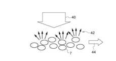
図3は、本実施形態に係る血管にレーザ光を照射した場合に生じるドップラーシフトの説明に供する模式図である。 FIG. 3 is a schematic diagram for explaining the Doppler shift that occurs when a laser beam is applied to a blood vessel according to this embodiment.
図3に示すように、例えばレーザ光のような周波数ω0のコヒーレント光40を発光素子1から血管の一例である毛細血管6を含む領域に照射した場合、毛細血管6を移動する血球細胞で散乱した散乱光42は、血球細胞の移動速度により決まる差周波Δω0を有するドップラーシフトを生じることになる。一方、血球細胞等の移動体を含まない皮膚等の組織(静止組織)で散乱した散乱光42の周波数は、照射したレーザ光の周波数と同じ周波数ω0を維持する。したがって、毛細血管6等の血管で散乱したレーザ光の周波数ω0+Δω0と、静止組織で散乱したレーザ光の周波数ω0とが互いに干渉し、差周波Δω0を有するビート信号が受光素子3で観測され、受光素子3の受光量が時間の経過に伴って変化する。なお、受光素子3で観測されるビート信号の差周波Δω0は血球細胞の移動速度に依存するが、約数十kHzを上限とした範囲に含まれる。As shown in FIG. 3, for example, when
また、3つ目の光学現象として、スペックルによる影響が考えられる。 Also, as the third optical phenomenon, the influence of speckle can be considered.
図4は、本実施形態に係る血管にレーザ光を照射した場合に生じるスペックルの説明に供する模式図である。 FIG. 4 is a schematic diagram for explaining speckles that occur when laser light is applied to a blood vessel according to the present embodiment.
図4に示すように、レーザ光のようなコヒーレント光40を、発光素子1から血管中を矢印44の方向に移動する赤血球等の血球細胞7に照射した場合、血球細胞7にぶつかったレーザ光は様々な方向に散乱する。散乱光は位相が異なるためにランダムに干渉し合う。これによりランダムな斑点模様の光強度分布を生じる。このようにして形成される光強度の分布パターンは「スペックルパターン」と呼ばれる。 As shown in FIG. 4, when
既に説明したように、血球細胞7は血管中を移動するため、血球細胞7における光の散乱状態が変化し、スペックルパターンが時間の経過と共に変動する。したがって、受光素子3の受光量が時間の経過に伴って変化する。 As already explained, since the blood cells 7 move through the blood vessel, the light scattering state of the blood cells 7 changes, and the speckle pattern changes over time. Therefore, the amount of light received by the
次に、血流情報の求め方の一例について説明する。図2に示す時間経過に伴う受光素子3の受光量が得られた場合、予め定めた単位時間T0の範囲に含まれるデータを切り出し、当該データに対して、例えば高速フーリエ変換(Fast Fourier Transform: FFT)を実行することで、周波数ω毎のスペクトル分布が得られる。Next, an example of how to obtain blood flow information will be described. When the amount of light received by the
図5は、本実施形態に係る単位時間T0における周波数ω毎のスペクトル分布の一例を示すグラフである。FIG. 5 is a graph showing an example of spectral distribution for each frequency ω in unit time T0 according to this embodiment.
なお、図5において、グラフ82の横軸は周波数ωを表し、縦軸はスペクトル強度を表す。 In FIG. 5, the horizontal axis of
ここで、血液量はグラフ82の横軸と縦軸とで囲まれた斜線領域84で表されるパワースペクトルの面積を全光量で規格化した値に比例する。また、血流速度はグラフ82で表されるパワースペクトルの周波数平均値に比例するため、周波数ωと周波数ωにおけるパワースペクトルの積を周波数ωについて積分した値を斜線領域84の面積で除算した値に比例する。 Here, the blood volume is proportional to the value obtained by normalizing the area of the power spectrum represented by the shaded
なお、血流量は血液量と血流速度の積で表わされるため、上記血液量と血流速度の算出式より求めることが可能である。血流量、血流速度、血液量は血流情報の一例であり、血流情報はこれに限定されない。 Since the blood flow is expressed as the product of the blood volume and the blood flow velocity, it can be obtained from the above formula for calculating the blood volume and the blood flow velocity. Blood flow, blood flow velocity, and blood volume are examples of blood flow information, and blood flow information is not limited to these.
図6は、本実施形態に係る単位時間T0あたりの血流量の変化の一例を示すグラフである。FIG. 6 is a graph showing an example of changes in blood flow per unit time T0 according to this embodiment.
なお、図6において、グラフ86の横軸は時間を表し、縦軸は血流量を表す。 In FIG. 6, the horizontal axis of
図6に示すように、血流量は時間と共に変動するが、その変動の傾向は2つの種類に分類される。例えば図6の区間T1における血流量の変動幅88に比べて、区間T2における血流量の変動幅90は大きい。これは、区間T1における血流量の変化が、主に脈の動きに伴う血流量の変化であるのに対して、区間T2における血流量の変化は、例えばうっ血や神経活動等の原因に伴う血流量の変化を示しているためであると考えられる。As shown in FIG. 6, the blood flow fluctuates over time, and the tendency of the fluctuation is classified into two types. For example, the
(酸素飽和度の測定)
次に、血中の酸素飽和度の測定について説明する。血中の酸素飽和度とは、血中酸素濃度の一例であり、血液中のヘモグロビンがどの程度酸素と結合しているかを示す指標であり、血中の酸素飽和度が低下するにつれ、貧血等の症状が発生しやすくなる。(Measurement of oxygen saturation)
Next, the measurement of blood oxygen saturation will be described. Blood oxygen saturation is an example of blood oxygen concentration, and is an index showing how much hemoglobin in blood binds to oxygen. symptoms are more likely to occur.
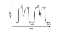
図7は、本実施形態に係る生体8に吸収される光の吸光量の変化の一例を示すグラフである。 FIG. 7 is a graph showing an example of changes in the amount of light absorbed by the living
なお、図7において、グラフ92の横軸は時間を表し、縦軸は吸光量を表す。 In FIG. 7, the horizontal axis of the
図7に示すように、生体8における吸光量は、時間の経過と共に変動する傾向が見られる。 As shown in FIG. 7, the amount of light absorbed by the living
更に、生体8における吸光の変動に関する内訳について見てみると、主に動脈4によって吸光量が変動し、静脈5及び静止組織を含むその他の組織では、動脈4に比べて吸光量が変動しないとみなせる程度の変動量であることが知られている。これは、心臓から拍出された動脈血は脈波を伴って血管内を移動するため、動脈4が動脈4の断面方向に沿って経時的に伸縮し、動脈4の厚みが変化するためである。なお、図7において、矢印94で示される範囲が、動脈4の厚みの変化に対応した吸光量の変動量を示す。 Furthermore, looking at the details of the variation in light absorption in the living
図7において、時刻taにおける受光量をIa、時刻tbにおける受光量をIbとすれば、動脈4の厚みの変化による光の吸光量の変化量ΔAは、(1)式で表される。In FIG. 7, if the amount of light received at time ta is Ia and the amount of light received at time tb is Ib , the amount of change ΔA in the amount of light absorption due to the change in the thickness of the
(数1)
ΔA=ln(Ib/Ia)・・・(1)(Number 1)
ΔA=ln(Ib /Ia ) (1)
図8は、本実施形態に係るヘモグロビンによる吸光度特性の一例を示すグラフである。 FIG. 8 is a graph showing an example of absorbance characteristics of hemoglobin according to this embodiment.
なお、図8において、縦軸は吸光度を表し、横軸は波長を表す。 In FIG. 8, the vertical axis represents absorbance and the horizontal axis represents wavelength.
図8に示すように、動脈4を流れる酸素と結合したヘモグロビン(酸化ヘモグロビン)は、特に約880nm近辺の波長を有する赤外線(infrared: IR)領域の光を吸収しやすく、酸素と結合していないヘモグロビン(還元ヘモグロビン)は、特に約665nm近辺の波長を有する赤色領域の光を吸収しやすいことが知られている。更に、酸素飽和度は、異なる波長における吸光量の変化量ΔAの比率と比例関係があることが知られている。 As shown in FIG. 8, hemoglobin bound to oxygen flowing through the artery 4 (oxyhemoglobin) is particularly likely to absorb light in the infrared (IR) region having a wavelength around 880 nm, and is not bound to oxygen. It is known that hemoglobin (reduced hemoglobin) is particularly apt to absorb light in the red region having a wavelength around 665 nm. Furthermore, it is known that the oxygen saturation has a proportional relationship with the ratio of the amount of change ΔA in the amount of light absorption at different wavelengths.
したがって、他の波長の組み合わせに比べて、酸化ヘモグロビンと還元ヘモグロビンとで吸光量の差が現われやすい赤外光(IR光)と赤色光を用いて、IR光を生体8に照射した場合の吸光量の変化量ΔAIRと、赤色光を生体8に照射した場合の吸光量の変化量ΔARedとの比率をそれぞれ算出することで、(2)式によって酸素飽和度Sが算出される。なお、(2)式においてkは比例定数である。Therefore, compared to other wavelength combinations, infrared light (IR light) and red light are more likely to cause a difference in the amount of light absorption between oxygenated hemoglobin and reduced hemoglobin. By calculating the ratio between the amount of change ΔAIR and the amount of change ΔARed in the amount of absorption when the living
(数2)
S=k(ΔARed/ΔAIR)・・・(2)(Number 2)
S=k(ΔARed /ΔAIR ) (2)
すなわち、血中の酸素飽和度を算出する場合、それぞれ異なる波長の光を照射する複数の発光素子1、具体的には、IR光を照射する発光素子1と赤色光を照射する発光素子1とを一部の発光期間が重複してもよいが、望ましくは発光期間が重複しないよう発光させる。そして、各々の発光素子1による反射光又は透過光を受光素子3で受光して、各受光時点における受光量から(1)式及び(2)式、又は、これらの式を変形して得られる公知の式を算出することで、酸素飽和度が測定される。 That is, when calculating the oxygen saturation in blood, a plurality of light-emitting
上記(1)式を変形して得られる公知の式として、例えば(1)式を展開して、光の吸光量の変化量ΔAを(3)式のように表してもよい。 As a known formula obtained by modifying the above formula (1), for example, formula (1) may be developed to express the amount of change ΔA in the amount of light absorption as in formula (3).
(数3)
ΔA=lnIb-lnIa・・・(3)(Number 3)
ΔA=lnIb -lnIa (3)
また、(1)式は(4)式のように変形することができる。 Also, equation (1) can be transformed into equation (4).
(数4)
ΔA=ln(Ib/Ia)=ln(1+(Ib-Ia)/Ia) ・・・(4)(Number 4)
ΔA=ln(Ib /Ia )=ln(1+(Ib -Ia )/Ia ) (4)
通常、(Ib-Ia)≪Iaであることから、ln(Ib/Ia)≒(Ib-Ia)/Iaが成り立つため、(1)式の代わりに、光の吸光量の変化量ΔAとして(5)式を用いてもよい。Since (Ib -Ia )<<Ia , ln(Ib /Ia )≈(Ib -Ia )/Ia is usually established. Equation (5) may be used as the amount of change ΔA in the amount of light absorption.
(数5)
ΔA≒(Ib-Ia)/Ia ・・・(5)(Number 5)
ΔA≈(Ib −Ia )/Ia (5)
なお、IR光を照射する発光素子1と赤色光を照射する発光素子1とを区別して説明する必要がある場合、以降では、IR光を照射する発光素子1を「発光素子LD1」といい、赤色光を照射する発光素子1を「発光素子LD2」というようにする。また、一例として、発光素子LD1を血流量の算出で使用する発光素子1とし、発光素子LD1及び発光素子LD2を、血中の酸素飽和度の算出で利用する発光素子1とする。 When it is necessary to distinguish between the light-emitting
また、血中の酸素飽和度を測定する場合、受光量の測定周波数は約30Hzから1000Hz程度で十分であることが知られているため、発光素子LD2の1秒あたりの点滅回数を表す発光周波数も約30Hzから1000Hz程度で十分である。したがって、発光素子LD2における消費電力等の観点からは、発光素子LD2の発光周波数を発光素子LD1の発光周波数より低くすることが好ましいが、発光素子LD2の発光周波数を発光素子LD1の発光周波数に合わせ、発光素子LD1と発光素子LD2を交互に発光させるようにしてもよい。 In addition, when measuring the oxygen saturation in blood, it is known that the measurement frequency of the amount of light received is sufficient at about 30 Hz to 1000 Hz. Also, about 30 Hz to 1000 Hz is sufficient. Therefore, from the viewpoint of power consumption of the light emitting element LD2, it is preferable to set the emission frequency of the light emitting element LD2 lower than that of the light emitting element LD1. , the light emitting element LD1 and the light emitting element LD2 may alternately emit light.
次に、図9を参照して、生体8の末梢部位から得られる脈波信号から呼吸波形を測定する原理について説明する。ここでいう末梢部位の一例としては、手の指先や、足の指先、耳たぶ等が挙げられる。なお、末梢部位には、肘よりも先の部位や、膝よりも先の部位等も含まれる。また、呼吸波形とは、生体8の呼吸状態を示す信号の波形であり、呼気及び吸気の時間変化を表す時系列信号の波形とされる。 Next, the principle of measuring a respiratory waveform from a pulse wave signal obtained from a peripheral site of the living
図9は、本実施形態に係る呼吸波形の測定原理の説明に供する模式図である。 FIG. 9 is a schematic diagram for explaining the principle of measuring a respiratory waveform according to this embodiment.
図9に示すように、吸気時には以下に示すステップにより脈波信号の振幅が減少する。
(S1)胸腔内圧が低下して陰圧となり、肺が拡張する。
(S2)静脈還流量が増加する。
(S3)右心房に流入する血液量が増加する。
(S4)肺の血管床が拡がり、肺が貯留する血液量が増加する。
(S5)肺から左心房に戻る血液量が減少する。
(S6)左心室の1回拍出量が減少する。
(S7)脈波信号の振幅が減少する。As shown in FIG. 9, during inspiration, the amplitude of the pulse wave signal decreases by the following steps.
(S1) The intrathoracic pressure decreases to negative pressure, and the lungs expand.
(S2) The venous return volume increases.
(S3) The amount of blood flowing into the right atrium increases.
(S4) The vascular bed of the lung expands and the amount of blood retained in the lung increases.
(S5) The amount of blood returning from the lungs to the left atrium decreases.
(S6) The stroke volume of the left ventricle decreases.
(S7) The amplitude of the pulse wave signal decreases.
一方、呼気時には以下に示すステップにより脈波信号の振幅が増加する。
(S8)肺から絞り出た血液が左心室に流入する。
(S9)脈波信号の振幅が増加する。On the other hand, during exhalation, the amplitude of the pulse wave signal increases through the following steps.
(S8) Blood squeezed out of the lungs flows into the left ventricle.
(S9) The amplitude of the pulse wave signal increases.
つまり、「心臓のポンプ動作」により生じる脈動に、呼吸により生じる「肺のポンプ動作」の影響が重畳されるため、生体8の末梢部位から得られる脈波信号から呼吸波形を測定することが可能となる。 In other words, since the pulsation caused by the "pumping action of the heart" is superimposed by the effect of the "pumping action of the lungs" caused by respiration, it is possible to measure the respiratory waveform from the pulse wave signal obtained from the peripheral part of the living
次に、図10を参照して、心臓からの血液の拍出量と相関がある指標の一例である酸素循環時間(Lung to Finger Circulation Time:LFCT)を測定する原理について説明する。ここでいう拍出量には、上述の心拍出量に限らず、1回拍出量、心係数等も含まれる。なお、心拍出量とは、心臓の単位時間(例えば1分)当たりの収縮によって動脈へ拍出される血液量と定義される。1回拍出量とは、心臓の1回の収縮によって動脈へ拍出される血液量と定義される。心係数とは、心拍出量を被測定者の体表面積で除して得られる係数と定義される。また、LFCTとは、呼吸で取り込まれた酸素が肺及び心臓を通り指先に到達するまでの時間と定義される。 Next, with reference to FIG. 10, the principle of measuring oxygen circulation time (Lung to Finger Circulation Time: LFCT), which is an example of an index correlated with the stroke volume of blood from the heart, will be described. The stroke volume referred to here is not limited to the above-described cardiac output, but also includes stroke volume, cardiac index, and the like. Cardiac output is defined as the volume of blood ejected into arteries by contraction of the heart per unit time (for example, 1 minute). Stroke volume is defined as the volume of blood pumped into an artery by one contraction of the heart. Cardiac index is defined as the coefficient obtained by dividing the cardiac output by the subject's body surface area. LFCT is defined as the time it takes for oxygen taken in by respiration to reach the fingertips through the lungs and heart.
図10は、本実施形態に係る拍出量の測定原理の説明に供する模式図である。 FIG. 10 is a schematic diagram for explaining the principle of measuring the stroke volume according to this embodiment.
図10に示すように、上記拍出量とLFCTとは相関がある。例えば拍出量の一例である心拍出量をCOとした場合、心拍出量COは、以下に示す(6)式により算出される。 As shown in FIG. 10, there is a correlation between the stroke volume and LFCT. For example, if CO is the cardiac output, which is an example of the cardiac output, the cardiac output CO is calculated by the following equation (6).
(数6)
CO=(a0×S)/LFCT・・・(6)(Number 6)
CO=(a0 ×S)/LFCT (6)
ここで、a0は定数であり、例えばa0=50が用いられる。また、Sは被測定者の体表面積(m2)であり、LFCTの単位は秒である。Here, a0 is a constant, and for example a0 =50 is used. Also, S is the body surface area (m2 ) of the subject, and the unit of LFCT is seconds.
図11は、本実施形態に係るLFCTの測定方法の一例を説明するためのグラフである。 FIG. 11 is a graph for explaining an example of the LFCT measurement method according to this embodiment.
なお、図11において、縦軸は酸素飽和度の逆数を表し、横軸は時間を表す。 In FIG. 11, the vertical axis represents the reciprocal of oxygen saturation, and the horizontal axis represents time.
図11に示すように、本実施形態に係るLFCTは、上述した酸素飽和度の変化から測定される。すなわち、LFCTは、一定期間呼吸を停止した後に呼吸を再開した時点から、酸素飽和度が回復し始めたことを示す変曲点までの時間を測定することで得られる。 As shown in FIG. 11, the LFCT according to this embodiment is measured from the change in oxygen saturation described above. That is, the LFCT is obtained by measuring the time from when breathing is resumed after stopping breathing for a certain period to an inflection point indicating that the oxygen saturation has started to recover.
なお、上記LFCTの測定では、血中酸素濃度の変化の検出に、一例として、IR光信号の変化量と赤色光信号の変化量との比率、つまり、波長が異なる2つの脈波信号(ここではIR光信号及び赤色光信号)の振幅比が用いられる。この振幅比を用いる場合、例えば心房細動を持つ生体や、環境温度や精神状態等の影響により血流量が低下している生体等に対して、血中酸素濃度を精度よく測定することが難しい場合がある。したがって、後ほど説明するように、IR光信号の変化量及び赤色光信号の変化量との差分を用いて血中酸素濃度を測定してもよい。 In the measurement of the LFCT, as an example, the ratio of the amount of change in the IR light signal to the amount of change in the red light signal, that is, two pulse wave signals with different wavelengths (here , the amplitude ratio of the IR light signal and the red light signal) is used. When using this amplitude ratio, it is difficult to accurately measure the blood oxygen concentration in a living body with atrial fibrillation, or in a living body with reduced blood flow due to environmental temperature, mental state, etc. Sometimes. Therefore, as described later, the difference between the amount of change in the IR light signal and the amount of change in the red light signal may be used to measure the blood oxygen concentration.
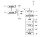
図12は、本実施形態に係る生体情報測定装置10の電気的な構成の一例を示すブロック図である。 FIG. 12 is a block diagram showing an example of the electrical configuration of the biological
図12に示すように、本実施形態に係る生体情報測定装置10は、発光制御部12、駆動回路14、増幅回路16、A/D(Analog/Digital)変換回路18、制御部20、表示部22、発光素子LD1、発光素子LD2、及び受光素子3を備えている。なお、発光素子LD1、発光素子LD2、受光素子3、及び増幅回路16は、センサ部を構成している。また、発光制御部12、駆動回路14、増幅回路16、A/D変換回路18、制御部20、及び表示部22は、本体部を構成している。本実施形態では、これらのセンサ部と本体部とは別体で構成され、有線又は無線を介して通信可能とされている。なお、センサ部と本体部とが一体的に構成されていてもよい。また、センサ部は、外部光が入力しないように生体8に密着するように取り付けられる。本実施形態に係るセンサ部は、一例として、生体8の指先に取り付けられるが、耳たぶ等の他の末梢部位にも取り付け可能とされている。 As shown in FIG. 12, the biological
発光制御部12は、発光素子LD1及び発光素子LD2に駆動電力を供給する電力供給回路を含む駆動回路14に、発光素子LD1及び発光素子LD2の発光周期及び発光期間を制御する制御信号を出力する。なお、発光制御部12は、制御部20の一部として実現してもよい。 The light
駆動回路14は、発光制御部12からの制御信号を受け付けると、制御信号で指示された発光周期及び発光期間に従って、発光素子LD1及び発光素子LD2に駆動電力を供給し、発光素子LD1及び発光素子LD2を駆動する。 Upon receiving the control signal from the light
受光素子3は、受光部の一例であり、発光素子LD1から第1の波長の光を受光し、受光した第1の波長の光に対応する第1の受光信号と、発光素子LD2から第2の波長の光を受光し、受光した第2の波長の光に対応する第2の受光信号と、を出力する。なお、本実施形態では、第1の波長として赤外領域に対応する波長の範囲が適用され、第2の波長として赤色領域に対応する波長の範囲が適用される。また、第1の受光信号にはIR光信号が適用され、第2の受光信号には赤色光信号が適用される。 The light-receiving
増幅回路16は、受光素子3で発生する光の強さに応じた電流を電圧に変換し、A/D変換回路18の入力電圧範囲として規定される電圧レベルまで増幅する。 The
A/D変換回路18は、増幅回路16で増幅した電圧を入力として、当該電圧の大きさで表される受光素子3の受光量を数値化して出力する。 The A/
制御部20は、CPU(Central Processing Unit)20A、ROM(Read Only Memory)20B、及びRAM(Random Access Memory)20Cを備えている。ROM20Bには、生体情報測定プログラムが記憶される。 The
表示部22は、生体情報の測定結果を通知する。表示部22には、例えば液晶ディスプレイ(LCD:Liquid Crystal Display)や有機EL(Electro Luminescence)ディスプレイ等が用いられる。表示部22は、タッチパネルを一体的に有している。 The
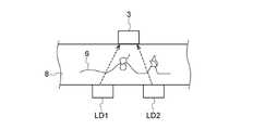
図13は、本実施形態に係る生体情報測定装置10における発光素子LD1、発光素子LD2、及び受光素子3の配置の一例を示す図である。また、図14は、本実施形態に係る生体情報測定装置10における発光素子LD1、発光素子LD2、及び受光素子3の配置の別の例を示す図である。 FIG. 13 is a diagram showing an example of arrangement of the light-emitting element LD1, the light-emitting element LD2, and the light-receiving
図13に示すように、発光素子LD1、発光素子LD2、及び受光素子3は、生体8の一方の面に向かって並べて配置される。この場合、受光素子3は、生体8の表面近傍を透過した発光素子LD1及び発光素子LD2の光を受光する。 As shown in FIG. 13, the light-emitting element LD1, the light-emitting element LD2, and the light-receiving
なお、発光素子LD1、発光素子LD2、及び受光素子3の配置は、図13の配置例に限定されない。例えば図14に示すように、発光素子LD1及び発光素子LD2と、受光素子3とを、生体8を挟んで対向する位置に配置するようにしてもよい。この場合、受光素子3は、生体8を透過した発光素子LD1及び発光素子LD2の光を受光する。 The arrangement of the light emitting element LD1, the light emitting element LD2, and the
なお、ここでは一例として、発光素子LD1及び発光素子LD2は、共に面発光レーザ素子であるものとして説明するが、これに限らず、端面発光レーザ素子であってもよい。また、発光素子LD1及び発光素子LD2の各々から照射される光はレーザ光でなくてもよい。この場合、発光素子LD1及び発光素子LD2の各々には、発光ダイオード(Light-Emitting Diode: LED)又は有機発光ダイオード(Organic Light-Emitting Diode: OLED)を用いてもよい。 Here, as an example, the light-emitting element LD1 and the light-emitting element LD2 are both surface-emitting laser elements, but they may be edge-emitting laser elements. Further, the light emitted from each of the light emitting element LD1 and the light emitting element LD2 may not be laser light. In this case, a light-emitting diode (LED) or an organic light-emitting diode (OLED) may be used for each of the light-emitting element LD1 and the light-emitting element LD2.
図15は、本実施形態に係る受光素子3におけるデータのサンプリングタイミングの一例を示すグラフである。図15において、丸印の位置がサンプリングタイミングを示している。 FIG. 15 is a graph showing an example of data sampling timing in the
なお、図15において、縦軸は受光素子3の出力電圧を表し、横軸は時間を表す。 In FIG. 15, the vertical axis represents the output voltage of the
図15に示すように、受光素子3が発光素子LD1から受光した光に対応する出力電圧を、IR1、IR2、・・・、IRnとした場合に、時系列データとしてIR(t)=IR1、IR2、・・・、IRnが得られる。同様に、受光素子3が発光素子LD2から受光した光に対応する出力電圧を、Red1、Red2、・・・、Rednとした場合に、時系列データとしてRed(t)=Red1、Red2、・・・、Rednが得られる。このとき、両方の発光素子LD1及び発光素子LD2に対して、発光しない期間を設け、暗状態での出力Dark1、Dark2、・・・、Darknを得るようにしてもよい。この場合、IR(t)は、IR1-Dark1、IR2-Dark2、・・・、IRn-Darknとしてもよい。同様に、Red(t)は、Red1-Dark1、Red2-Dark2、・・・、Redn-Darknとしてもよい。これらのデータのサンプリングは、発光期間の終了近くで出力が安定している状態で行うことが望ましい。As shown in FIG. 15, when the output voltage corresponding to the light receivedby the
図16は、生体情報測定装置10の機能的な構成の一例を示すブロック図である。 FIG. 16 is a block diagram showing an example of the functional configuration of the biological
図16に示すように、本実施形態に係る生体情報測定装置10は除去部30、補正部31、測定部32、検出部33、特定部34、推定部35、及び報知部36の各機能部を含む。更に、特定部34には抽出部37が含まれる。除去部30は、生体情報測定装置10に必須の構成要素ではなく、必要に応じて設けるようにすればよい。 As shown in FIG. 16, the biological
CPU20Aは、ROM20Bに記憶されている生体情報測定プログラムを実行することにより、図16に示す各機能部として機能する。 CPU20A functions as each functional part shown in FIG. 16 by running the biometric information measurement program memorize|stored in ROM20B.
まず、除去部30を設けない場合の各部の構成について説明する。 First, the configuration of each section when the
本実施形態に係る補正部31は、受光素子3から出力されたIR光信号及び赤色光信号の各々を受け付け、生体8の動脈血液量の変化に伴う、IR光信号の変化量(以下、ΔIRという。)と赤色光信号の変化量(以下、ΔRedという。)との差が小さくなるように、IR光信号を補正する。この動脈血液量の変化は、心拍に伴う脈動の振幅を表している。IR光信号は第1の信号の一例であり、赤色光信号は第2の信号の一例である。 The
上記補正は、ΔIRとΔRedとを同一にする補正であることが望ましい。ここで、ΔIRは、IR光信号の振幅として表され、ΔRedは、赤色光信号の振幅として表される。この場合、上記補正は、ΔIRとΔRedとの振幅比(ΔRed/ΔIR)で表される係数αを、IR光信号の値(IR(t))に乗じることで行われる。つまり、IR(t)の補正後の出力は、α×IR(t)となる。 It is desirable that the above correction be a correction to make ΔIR and ΔRed the same. where ΔIR is expressed as the amplitude of the IR light signal and ΔRed is expressed as the amplitude of the red light signal. In this case, the above correction is performed by multiplying the IR light signal value (IR(t)) by a coefficient α represented by the amplitude ratio of ΔIR and ΔRed (ΔRed/ΔIR). That is, the corrected output of IR(t) is α×IR(t).
本実施形態に係る測定部32は、補正部31により補正されたIR光信号及び赤色光信号に基づいて、生体8における血中酸素濃度、具体的には酸素飽和度を測定する。そして、測定部32は、LFCTを測定するために呼吸を停止した被測定者の血中酸素濃度が呼吸を停止する前より低下したことを測定した場合、報知部36に通知する。なお、酸素飽和度は血中酸素濃度の一例であることから、以降では、血中酸素濃度の変化と相関関係のある生体情報を総称して「血中酸素濃度」ということにする。 The
報知部36は、測定部32から被測定者の血中酸素濃度が低下したことを通知された場合、被測定者に対して呼吸を再開するように報知する。 When notified by the
また、測定部32は被測定者が呼吸を再開した後、LFCTを測定するため、一例として補正部31により補正されたIR光信号及び赤色光信号との差(以下、この差を「脈波差」という。)を測定する。例えば脈波差をβ(t)とした場合、β(t)は、以下に示す(7)式により求められる。 In addition, since the
(数7)
β(t)=α×IR(t)-Red(t)・・・(7)(Number 7)
β(t)=α×IR(t)−Red(t) (7)
本実施形態に係る検出部33は、測定部32により測定された脈波差β(t)に基づいて、生体8の吸気酸素量の変化に伴う血中酸素濃度の変曲点を検出する。なお、吸気酸素量を変化させる方法としては、一例として、息止めによる方法等が挙げられる。また、ここでいう吸気酸素量の変化とは、少なくとも数秒間に渡り血中酸素濃度に変化を及ぼす変化であって、通常の呼吸状態(例えば平均的な呼吸回数及び深さでの呼吸)による僅かな変化は含まないものとする。つまり、通常の呼吸状態では、吸気酸素量に変化はなく、呼吸を停止する、呼吸を弱める、酸素濃度の高い気体を吸い込む等により通常の呼吸状態から変化させた場合に、吸気酸素量が変化したと判断される。 Based on the pulse wave difference β(t) measured by the
本実施形態に係る特定部34は、生体8の吸気酸素量が変化した時点から、検出部33により検出された血中酸素濃度の変曲点までの時間を特定する。なお、吸気酸素量が変化した時点とは、例えば呼吸停止の状態から呼吸を再開した時点等である。 The specifying
特定部34は、IR光信号または赤色光信号によって表される脈波信号から被測定者の呼吸波形を抽出する抽出部37を含む。したがって、特定部34は、抽出部37で抽出された呼吸波形から、被測定者が呼吸を再開した時点を特定すればよい。本実施形態では、特定部34により特定された時間をLFCTとする。 The
なお、本実施形態に係る呼吸波形抽出部の一例である抽出部37は、生体情報測定装置10に必須の構成要素ではなく、特定部34が被測定者の呼吸の再開を呼吸波形からではなく他の方法で特定する場合には不要となる。 Note that the
本実施形態に係る推定部35は、特定部34により特定されたLFCTから拍出量を推定する。例えば上記(6)式を用いて、拍出量の一例である心拍出量を推定する。 The
ここで、IR光信号及び赤色光信号の各々には、脈動や神経活動などによる血液量の変化を表す成分と、吸気酸素量の変化による酸素濃度の変化を表す成分と、が含まれている。そして、上記脈波差β(t)によれば、係数α(=ΔRed/ΔIR)をIR(t)に乗じ、α×IR(t)とRed(t)との差を採用することで、動脈血の血液量の変化を表す成分が相殺され、酸素濃度の変化を表す成分のみが抽出される。 Here, each of the IR light signal and the red light signal contains a component representing changes in blood volume due to pulsation, nerve activity, etc., and a component representing changes in oxygen concentration due to changes in the amount of inspired oxygen. . Then, according to the pulse wave difference β(t), by multiplying IR(t) by a coefficient α(=ΔRed/ΔIR) and adopting the difference between α×IR(t) and Red(t), Components representing changes in arterial blood volume are canceled out, and only components representing changes in oxygen concentration are extracted.
なお、上記では、IR光信号を補正するために、係数αを(ΔRed/ΔIR)としたが、赤色光信号を補正するために、係数αを(ΔIR/ΔRed)としてもよい。この場合、脈波差β(t)は、以下に示す(8)式により求められる。 In the above description, the coefficient α is set to (ΔRed/ΔIR) to correct the IR light signal, but the coefficient α may be set to (ΔIR/ΔRed) to correct the red light signal. In this case, the pulse wave difference β(t) is obtained by the following equation (8).
(数8)
β(t)=IR(t)-α×Red(t)・・・(8)(Number 8)
β(t)=IR(t)−α×Red(t) (8)
また、上記では、2つの脈波信号の一例であるIR光信号及び赤色光信号のいずれか一方を補正する場合について説明したが、IR光信号及び赤色光信号の両方を補正するようにしてもよい。また、上記では、IR光信号から赤色光信号を減じたが、赤色光信号からIR光信号を減じても構わない。その場合、β(t)にあらわれる変曲点の向きが異なる。 Further, in the above description, the case of correcting either one of the IR light signal and the red light signal, which are examples of the two pulse wave signals, has been described. good. Also, in the above description, the red light signal is subtracted from the IR light signal, but the IR light signal may be subtracted from the red light signal. In that case, the direction of the inflection point appearing in β(t) is different.
なお、係数αを求めるときの脈波信号と、求めた係数αを適用する脈波信号とは時間的にずれている。つまり、上記補正は、吸気酸素量を変化させる前におけるΔIRとΔRedとの振幅比で表される係数αを、吸気酸素量を変化させた後におけるIR(t)又はRed(t)に乗じることで行われる。例えば係数αを求めるときの脈波信号は、呼吸停止前の安静時における脈波信号を用いることが望ましい。 It should be noted that the pulse wave signal when obtaining the coefficient α and the pulse wave signal to which the obtained coefficient α is applied are temporally shifted. That is, the above correction is performed by multiplying IR(t) or Red(t) after changing the intake oxygen amount by a coefficient α represented by the amplitude ratio between ΔIR and ΔRed before changing the intake oxygen amount. is done in For example, as the pulse wave signal for obtaining the coefficient α, it is desirable to use the pulse wave signal at rest before breathing stops.
次に、除去部30を設けた場合の各部の構成について説明する。 Next, the configuration of each section when the
本実施形態に係る除去部30は、受光素子3から出力されたIR光信号及び赤色光信号の各々から直流成分を除去し、直流成分を除去した後のIR光信号及び赤色光信号の各々を補正部31に出力する。除去部30には、一例として、ハイパスフィルタ又はバンドパスフィルタが適用される。なお、この場合、除去部30により直流成分が除去されたIR光信号が第1の信号とされ、除去部30により直流成分が除去された赤色光信号が第2の信号とされる。 The removing
補正部31は、除去部30により直流成分が除去されたIR光信号及び赤色光信号を受け付け、受け付けたIR光信号の振幅と赤色光信号の振幅との振幅比で表される係数αを導出する。その後、補正部31は、受光素子3から除去部30を介さずに受け付けたIR光信号の値であるIR(t)又は赤色光信号の値であるRed(t)に対して、上記導出した係数αを乗じることで、補正を行う。なお、測定部32、検出部33、特定部34、推定部35、報知部36、及び抽出部37の動作は同じであるため説明を省略する。 The
次に、生体情報測定装置10の動作について説明する。図17は、被測定者又は測定担当者の操作により生体情報測定装置10が起動した場合に、生体情報測定装置10のCPU20Aによって実行される測定処理の流れの一例を示すフローチャートである。 Next, the operation of the biological
測定処理を規定する生体情報測定プログラムは、例えば生体情報測定装置10のROM20Bに予め記憶されている。生体情報測定装置10のCPU20Aは、ROM20Bに記憶される生体情報測定プログラムを読み込み、測定処理を実行する。 A biological information measurement program that defines the measurement process is stored in advance in the
ステップ100において、CPU20Aは、受光素子3から得られるIR光信号の振幅(ΔIR)を取得し、受光素子3から得られる赤色光信号の振幅(ΔRed)を取得する。このステップ100では、まず、被測定者が安静状態を保った状態で、脈波振幅として、ΔIR及びΔRedの各々を取得する。 At
図18は、本実施形態に係るIR光信号の振幅及び赤色光信号の振幅の一例を示すグラフである。 FIG. 18 is a graph showing an example of the amplitude of the IR light signal and the amplitude of the red light signal according to this embodiment.
なお、図18において、縦軸は受光素子3の出力電圧を表し、横軸は時間を表す。 In FIG. 18, the vertical axis represents the output voltage of the
図18に示すように、補正部31は、IR光信号の値の時系列データであるIR(t)からΔIRを取得し、赤色光信号の値の時系列データであるRed(t)からΔRedを取得する。 As shown in FIG. 18, the
ステップ102において、CPU20Aは、ステップ100で取得したΔIR及びΔRedに基づいて、ΔIRとΔRedとの振幅比で表される係数αを導出する。係数αは、一例として、以下に示す方法で導出される。
(a)任意のタイミングで得られた振幅比を採用する。なお、この場合、LFCTの測定開始後でもよい。
(b)一定期間で得られた複数の振幅比の平均値を採用する。この方法の場合、一点のみの振幅比を採用して係数αを導出する場合と比較し、測定に適した係数αが求められる。
(c)測定終了後に、一例として、図19に示すように、係数αを0~1の間で変化させ、脈波差β(t)に現れる脈動の周波数成分が最も小さい値を採用する。但し、係数αを(ΔRed/ΔIR)とした場合、ΔIR>ΔRedの条件を満たすものとする。この方法の場合、測定中に係数αを導出する必要がないため、例えば測定時間が短縮される。At
(a) Adopt an amplitude ratio obtained at an arbitrary timing. In this case, it may be after the start of LFCT measurement.
(b) Employing an average value of a plurality of amplitude ratios obtained over a certain period of time. In the case of this method, a coefficient α suitable for measurement can be obtained as compared with the case of deriving the coefficient α by adopting the amplitude ratio of only one point.
(c) After the measurement, as an example, as shown in FIG. 19, the coefficient α is changed between 0 and 1, and the value with the smallest pulsation frequency component appearing in the pulse wave difference β(t) is adopted. However, when the coefficient α is (ΔRed/ΔIR), the condition of ΔIR>ΔRed is satisfied. With this method, it is not necessary to derive the coefficient α during the measurement, thus shortening the measurement time, for example.
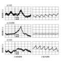
図19は、本実施形態に係る係数αと脈波差β(t)との関係の一例を示すグラフである。 FIG. 19 is a graph showing an example of the relationship between the coefficient α and the pulse wave difference β(t) according to this embodiment.
なお、図19において、縦軸は脈波差β(t)を表す。また、この例では、α=ΔRed/ΔIR、β(t)=α×IR(t)-Red(t)、である。 In FIG. 19, the vertical axis represents the pulse wave difference β(t). Also, in this example, α=ΔRed/ΔIR and β(t)=α×IR(t)−Red(t).
図19の上図は、係数α=0.2の場合における脈波差β(t)の全体波形及び拡大波形を示す。左図が全体波形であり、右図が拡大波形である。 The upper diagram in FIG. 19 shows the entire waveform and expanded waveform of the pulse wave difference β(t) when the coefficient α=0.2. The left figure is the overall waveform, and the right figure is the expanded waveform.
図19の中図は、係数α=0.3583の場合における脈波差β(t)の全体波形及び拡大波形を示す。左図が全体波形であり、右図が拡大波形である。 The middle diagram in FIG. 19 shows the overall waveform and expanded waveform of the pulse wave difference β(t) when the coefficient α=0.3583. The left figure is the overall waveform, and the right figure is the expanded waveform.
図19の下図は、係数α=0.6の場合における脈波差β(t)の全体波形及び拡大波形を示す。左図が全体波形であり、右図が拡大波形である。 The lower diagram of FIG. 19 shows the overall waveform and expanded waveform of the pulse wave difference β(t) when the coefficient α=0.6. The left figure is the overall waveform, and the right figure is the expanded waveform.
上記より、係数α=0.3583の場合に、脈波差β(t)に現れる脈動の周波数成分が最も小さくなることが分かる。従って、上記(c)の方法によれば、係数α=0.3583が採用、酸素濃度の変曲点が正しい位置にある脈波差β(t)が得られる。 From the above, it can be seen that the pulsation frequency component appearing in the pulse wave difference β(t) is the smallest when the coefficient α=0.3583. Therefore, according to the above method (c), the coefficient α=0.3583 is adopted, and the pulse wave difference β(t) with the inflection point of the oxygen concentration at the correct position is obtained.
ステップ104において、CPU20Aは、被測定者が安静状態を保った状態で、LFCTの測定開始の指示を受け付ける。この測定開始の指示は、一例として、被測定者又は測定担当者が表示部22のタッチパネル等を介して測定開始を指示することで行われる。 At
ステップ106において、CPU20Aは、被測定者に対して、息止め開始の指示を行う。具体的には、例えば表示部22に「息を止めて下さい。」等のメッセージを表示させることで行ってもよいし、音声や振動による指示でもよい。 At
既に説明したように、LFCTは、血中酸素濃度が低下するように呼吸を停止し、その後に呼吸を再開してから血中酸素濃度が回復し始めるまでの時間である。したがって、LFCTを測定するためには、血中酸素濃度が低下するように、例えば20秒程度呼吸を止める必要がある。しかしながら、呼吸を停止してから血中酸素濃度が低下するまでの時間には個人差があり、一律に長い時間呼吸を停止させることは被測定者によっては負担になる。したがって、血中酸素濃度が低下し始めたら被測定者の呼吸を再開させることが望ましい。 As explained above, the LFCT is the time between holding and then resuming breathing so that blood oxygen levels begin to recover. Therefore, in order to measure LFCT, it is necessary to hold the breath for about 20 seconds, for example, so that the blood oxygen concentration decreases. However, there are individual differences in the time from when breathing is stopped until the blood oxygen level decreases, and it is a burden for some subjects to uniformly stop breathing for a long period of time. Therefore, it is desirable to resume breathing of the subject when the blood oxygen level begins to decrease.
そこで、被測定者の血中酸素濃度が呼吸を停止する前より低下したことを表す予め定めた低下条件を設定しておき、CPU20Aは、血中酸素濃度の変化が低下条件を満たした場合に、被測定者の血中酸素濃度が呼吸を停止する前より低下したと判定して、被測定者に呼吸の再開を指示し、LFCTの測定を開始する。 Therefore, a predetermined lowering condition indicating that the blood oxygen concentration of the person to be measured is lower than that before stopping breathing is set, and the
予め設定する血中酸素濃度の低下条件は、被測定者の血中酸素濃度が低下したことが定量的に判定可能な条件であればどのような条件であってもよい。 The blood oxygen concentration lowering condition set in advance may be any condition as long as it is a condition that allows quantitative determination that the blood oxygen concentration of the person to be measured has decreased.
例えば血中酸素濃度が予め定めた基準閾値よりも低下することを血中酸素濃度の低下条件に設定する。基準閾値には各被測定者に共通した値を用いてもよいが、被測定者が呼吸を停止する前の血中酸素濃度、すなわち平常時の血中酸素濃度には個人差があるため、被測定者毎に、各々の平常時の血中酸素濃度にあわせて設定した基準閾値を用いてもよい。基準閾値は、例えばROM20Bに予め記憶されるが、測定担当者によって変更可能な値である。 For example, a blood oxygen concentration lowering than a predetermined reference threshold is set as the blood oxygen concentration lowering condition. A value common to each person to be measured may be used as the reference threshold, but the blood oxygen concentration before the person to be measured stops breathing, that is, the normal blood oxygen concentration varies among individuals. A reference threshold set according to the normal blood oxygen concentration of each subject may be used. The reference threshold value is stored in advance in the
しかしながら、被測定者が呼吸を停止させたからといって、測定される血中酸素濃度は測定誤差などから単調減少するわけではなく、実際には微小な増減を伴いながら、全体の傾向として見た場合に低下していく。 However, even if the subject stops breathing, the measured blood oxygen concentration does not monotonically decrease due to measurement errors. decrease in the case.
したがって、被測定者の血中酸素濃度が基準閾値よりも低下した後に、再び血中酸素濃度が基準閾値以上の値になってしまった場合、どの時点で被測定者に呼吸の再開を指示してLFCTの測定を開始すればよいのか判断に迷ってしまうことになる。 Therefore, when the blood oxygen level of the person to be measured falls below the reference threshold and then rises above the reference threshold again, at what point should the person be instructed to resume breathing? Therefore, it is difficult to determine whether the LFCT measurement should be started.
そこで、血中酸素濃度が基準閾値よりも低下し、かつ、血中酸素濃度が基準閾値よりも低下した直後に設けた規定期間における血中酸素濃度の統計量が、基準閾値よりも低下することを血中酸素濃度の低下条件に設定してもよい。本実施形態に係る予め定めた期間の一例である規定期間は、例えばROM20Bに予め記憶され、測定担当者によって変更可能な値である。 Therefore, the blood oxygen concentration falls below the reference threshold, and the statistic of the blood oxygen concentration in a specified period set immediately after the blood oxygen concentration falls below the reference threshold falls below the reference threshold. may be set as the blood oxygen concentration lowering condition. A specified period, which is an example of a predetermined period according to the present embodiment, is a value that is stored in advance in the
規定期間における血中酸素濃度の統計量とは、例えば規定期間に測定した血中酸素濃度の平均値、最低値、及び中央値等、規定期間における血中酸素濃度の代表値のことである。 The statistic of blood oxygen concentration in a specified period is a representative value of blood oxygen concentration in a specified period, such as an average value, minimum value, and median value of blood oxygen concentration measured in a specified period.
なお、血中酸素濃度が基準閾値よりも低下した直後は、血中酸素濃度が再び基準閾値以上の値になる傾向が見られることから、規定期間の後半に測定された血中酸素濃度ほど統計量に与える影響が大きくなるように重み付けを行った血中酸素濃度の加重平均を用いてもよい。 Immediately after the blood oxygen concentration falls below the reference threshold, there is a tendency for the blood oxygen concentration to rise above the reference threshold again. A weighted average of blood oxygen levels that are weighted so that the effect on volume is greater may be used.
また、血中酸素濃度の微小な増減に左右されずに血中酸素濃度の全体的な変化の傾向を把握するため、CPU20Aは、規定期間における血中酸素濃度の低下の度合いを算出し、算出した血中酸素濃度の低下の度合いによって、被測定者の血中酸素濃度が呼吸を停止する前より低下したか判定してもよい。 In addition, in order to grasp the tendency of the overall change in blood oxygen concentration without being influenced by minute increases or decreases in blood oxygen concentration, the
具体的には、CPU20Aは、測定した血中酸素濃度に対して最小二乗法を適用して、血中酸素濃度の全体的な変化の傾向を示す回帰直線を算出する。回帰直線は縦軸を血中酸素濃度、横軸を時間とするグラフで表されることから、算出した回帰直線の傾きが血中酸素濃度の低下の度合いを表す。したがって、回帰直線の傾きが、本実施形態に係る予め定めた基準の低下度合いの一例である基準低下度を超えることを血中酸素濃度の低下条件に設定する。 Specifically, the
基準低下度は、血中酸素濃度が低下し始めた場合に測定される回帰直線の傾きのことである。したがって、回帰直線の傾きが基準低下度を超えた場合に、血中酸素濃度が低下し始めたことを表す。基準低下度は、例えば複数の被測定者から得られた血中酸素濃度の測定データや、コンピュータシミュレーションの結果により予め決定され、ROM20Bに予め記憶される。基準低下度として各被測定者に共通した値を用いてもよいが、基準閾値と同じく、呼吸を停止した場合における血中酸素濃度の低下の度合いにも個人差があるため、被測定者毎に異なる基準低下度を用いるようにしてもよい。 The reference degree of decline is the slope of the regression line measured when the blood oxygen level begins to decline. Therefore, when the slope of the regression line exceeds the reference degree of decrease, it indicates that the blood oxygen concentration has started to decrease. The reference degree of decrease is determined in advance based on, for example, measurement data of blood oxygen levels obtained from a plurality of subjects or results of computer simulation, and is stored in the
更に言えば、上述したように、血中酸素濃度を測定するセンサ部の取り付け部位は必ずしも被測定者の指先である必要はないため、例えば被測定者の耳たぶにセンサ部を取り付けて血中酸素濃度を測定してもよい。この場合、血中酸素濃度を測定する部位の違いによって体表から血管までの距離や体の脂肪量等が異なるため、平常時の血中酸素濃度に相関を持つ生体情報にも違いが生じることがある。したがって、血中酸素濃度を測定する部位によって、異なる基準閾値を用いるようにすることが好ましい。 Furthermore, as described above, the attachment site of the sensor unit for measuring the blood oxygen concentration does not necessarily have to be the fingertip of the person to be measured. Concentration may be measured. In this case, the distance from the body surface to the blood vessels and the amount of fat in the body differ depending on the site where the blood oxygen concentration is measured, so there will be differences in the biological information that correlates with the normal blood oxygen concentration. There is Therefore, it is preferable to use different reference thresholds depending on the site where the blood oxygen concentration is measured.
上記に示した血中酸素濃度の低下条件は、血中酸素濃度が基準閾値よりも低下することを前提とした条件であったが、基準閾値の設定が困難な場合には、血中酸素濃度を基準閾値と比較することなく、基準低下度と比較するものであってもよい。具体的には、血中酸素濃度の低下の度合いが基準低下度を超えることを血中酸素濃度の低下条件に設定する。 The conditions for lowering the blood oxygen concentration shown above were based on the premise that the blood oxygen concentration would be lower than the reference threshold. may be compared with the reference degree of decrease without comparing with the reference threshold. Specifically, the blood oxygen concentration lowering condition is set such that the degree of lowering of the blood oxygen concentration exceeds a reference degree of lowering.
CPU20Aは、被測定者が呼吸を停止させた後の期間を予め定めた長さの期間(「分割期間」という)に分割し、分割期間毎に血中酸素濃度の変化を示す回帰直線を算出して基準低下度と比較することで、被測定者の血中酸素濃度が呼吸を停止する前より低下したか判定する。 The
ステップ108において、CPU20Aは、測定した血中酸素濃度が血中酸素濃度の低下条件を満たしたか否かによって、被測定者の呼吸の停止に伴って血中酸素濃度が低下したか否かを判定する。被測定者の血中酸素濃度が低下していない場合には、血中酸素濃度が低下条件を満たしているかの判定を繰り返し実行する。一方、被測定者の血中酸素濃度が低下した場合にはステップ110に移行する。 At
なお、被測定者によっては、体調の状態により血中酸素濃度が低下するまで時間を要し、血中酸素濃度が低下したと判定されるまで息が続かないようなことがある。このような場合、被測定者に過度な負担を強いることになる。したがって、ステップ106で被測定者に対して息止め開始の指示を行ってから予め定めた待機時間が経過しても、被測定者の血中酸素濃度が低下しないような場合には、待機時間経過後に呼吸の再開を指示し、被測定者にしばらく休憩してもらってから、再度ステップ100から測定処理をやり直すようにしてもよい。 It should be noted that depending on the subject's physical condition, it may take time for the blood oxygen concentration to decrease, and the person may not be able to breathe until it is determined that the blood oxygen concentration has decreased. In such a case, an excessive burden is imposed on the person to be measured. Therefore, if the blood oxygen level of the person to be measured does not decrease even after a predetermined waiting time elapses after the subject is instructed to start holding his or her breath in
被測定者の血中酸素濃度が低下したことにより、ステップ110において、CPU20Aは被測定者に対して呼吸再開の指示を行う。具体的には、例えば表示部22に呼吸を再開するように指示したメッセージを表示させることで行ってもよいし、音声や振動による指示でもよい。CPU20Aは、呼吸の再開時間からLFCTの測定を開始する。 In
被測定者の呼吸の再開時間は、例えば被測定者に対して呼吸の再開を指示した時間とすればよいが、被測定者に呼吸の再開を指示しても、被測定者が実際に呼吸を再開するまでには時間差が生じることがある。したがって、CPU20Aは、呼吸の再開を指示するタイミングに向けてカウントダウン等を行い、被測定者に呼吸を再開するタイミングを事前に知らせるようにしてもよい。 The respiration time of the person to be measured may be, for example, the time when the person to be measured is instructed to resume breathing. There may be a time lag before restarting. Therefore, the
また、例えば押下することでCPU20Aに再開通知を通知するボタンを被測定者に持たせ、生体情報測定装置10からの呼吸再開の指示の後、被測定者が呼吸を再開したタイミングで被測定者自身にボタンを押下させるようにしてもよい。この場合、CPU20Aは、再開通知を受け付けた時間を被測定者の呼吸の再開時間とする。 In addition, for example, the subject is given a button that, when pressed, notifies the
また、CPU20Aは、公知の手法を用いて、脈波から被測定者の呼吸波形を抽出し、抽出した呼吸波形から呼吸の再開時間を特定するようにしてもよい。 Further, the
具体的には、CPU20Aは、脈波の変化を示すグラフからピーク変曲点及びボトム変曲点を抽出し、ピーク変曲点間、及びボトム変曲点間をそれぞれスプライン補間等の公知の補間手法で補間して生成したピーク波形とボトム波形を生成する。「ピーク変曲点」とは、脈波の値が上昇から下降に転じる点であり、「ボトム変曲点」とは、脈波の値が下降から上昇に転じる点である。 Specifically, the
そして、CPU20Aは、ピーク波形とボトム波形の差分波形を生成し、生成した差分波形に対して高速フーリエ変換を実施して、差分波形に含まれる周波数成分を算出する。更に、CPU20Aは、算出した周波数成分から最大周波数成分を求め、求めた最大周波数成分と隣り合う前後の成分の周波数をそれぞれ遮断周波数に設定した後、例えばバンドパスフィルタを用いてそれぞれの遮断周波数の間に含まれる周波数成分だけを残し、それ以外の周波数成分を除去することで呼吸波形を抽出する。 Then, the
ステップ112において、CPU20Aは、呼吸再開後、所定時間経過したか否かを判定する。この所定時間は、経過観察のための時間として予め設定されており、一例として、60秒間等である。なお、測定部位によって酸素の到達時間が異なるため、測定部位に適した経過観察のための時間を予め設定しておくとよい。所定時間が経過した場合にはステップ114に移行し、所定時間が経過していないと判定した場合には、所定時間が経過するまでステップ112の判定処理を繰り返し実行して、所定時間が経過するまで待機する。なお、CPU20Aは所定時間が経過するまで待機している間、IR(t)及びRed(t)を測定し続ける。 At
ステップ114において、CPU20Aは、上記ステップ102で導出した係数αを、上記の測定により得られたIR(t)又はRed(t)に乗じることで補正を行う。なお、本実施形態では、係数α(ΔRed/ΔIR)をIR(t)に乗じて補正しているが、Red(t)を補正する場合、係数αを、ΔIR/ΔRed、とすればよい。 At step 114, the
図20は、本実施形態に係るIR光信号の時系列データ及び赤色光信号の時系列データの一例を示すグラフである。 FIG. 20 is a graph showing an example of time-series data of an IR light signal and time-series data of a red light signal according to this embodiment.
なお、図20において、縦軸は受光素子3の出力電圧を表し、横軸は時間を表す。 In FIG. 20, the vertical axis represents the output voltage of the
図20に示すように、グラフg1は、IR光信号の時系列データであるIR(t)を表す。また、グラフg2は、赤色光信号の時系列データであるRed(t)を表す。 As shown in FIG. 20, graph g1 represents IR(t), which is time-series data of the IR light signal. A graph g2 represents Red(t), which is the time-series data of the red light signal.
図21は、本実施形態に係る補正後のIR光信号の時系列データ及び赤色光信号の時系列データの一例を示すグラフである。 FIG. 21 is a graph showing an example of corrected time-series data of the IR light signal and time-series data of the red light signal according to the present embodiment.
なお、図21において、縦軸は受光素子3の出力電圧を表し、横軸は時間を表す。 In FIG. 21, the vertical axis represents the output voltage of the
図21に示すように、グラフg3は、IR(t)に係数αを乗じてオフセットを調整したα×IR(t)を表す。また、グラフg4は、赤色光信号の時系列データであるRed(t)を表す。 As shown in FIG. 21, a graph g3 represents α×IR(t) obtained by multiplying IR(t) by a coefficient α to adjust the offset. A graph g4 represents Red(t), which is the time-series data of the red light signal.
次に、ステップ116において、CPU20Aは、ステップ114で補正して得られたα×IR(t)、及び、Red(t)から、上記(7)式を用いて脈波差β(t)を測定する。なお、Red(t)を補正した場合には、上記(8)式を用いて脈波差β(t)を算出すればよい。 Next, at
ステップ118において、CPU20Aは、ステップ116で算出した脈波差β(t)に基づいて、被測定者の吸気酸素量の変化に伴う血中酸素濃度の変曲点を検出する。 At
ステップ120において、CPU20Aは、被測定者の吸気酸素量が変化した時点から、ステップ118で検出した変曲点までの時間を、LFCTとして特定し、本生体情報測定プログラムによる一連の処理を終了する。なお、本実施形態では、LFCTの特定までの処理について説明したが、特定したLFCTを用いて拍出量を算出するようにしてもよい。具体的には、例えば特定したLFCTを上記(6)式に適用して心拍出量を算出してもよい。 At
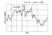
図22は、本実施形態に係る脈波差β(t)から特定されたLFCTの一例を示すグラフである。図22では、縦軸は脈波差β(t)を表し、横軸は時間を表す。また、図23は、比較例に係る振幅比から特定されたLFCTを示すグラフである。図23では、縦軸はΔIRとΔRedの振幅比を表し、横軸は時間を表す。 FIG. 22 is a graph showing an example of LFCT identified from the pulse wave difference β(t) according to this embodiment. In FIG. 22, the vertical axis represents the pulse wave difference β(t), and the horizontal axis represents time. Also, FIG. 23 is a graph showing the LFCT specified from the amplitude ratio according to the comparative example. In FIG. 23, the vertical axis represents the amplitude ratio of ΔIR and ΔRed, and the horizontal axis represents time.
図22に示すように、呼吸を再開した時点から、脈波差β(t)(=α×IR(t)-Red(t))の最大値により示される変曲点までの時間をLFCTとする。 As shown in FIG. 22, the time from the point of resuming breathing to the point of inflection indicated by the maximum value of the pulse wave difference β(t) (=α×IR(t)−Red(t)) is LFCT. do.
なお、図22において、グラフg5は、脈波差β(t)を片幅nデータ(この例ではn=64)の移動平均として表したものである。また、グラフg6は、係数α=0.3583とした場合の脈波差β(t)を表す。このように、脈波差β(t)を片幅nデータの移動平均とすることで、血中酸素濃度の違いによる残留脈波成分が除去されるため、より精度の高いLFCTが得られる。 In FIG. 22, a graph g5 represents the pulse wave difference β(t) as a moving average of single-width n data (n=64 in this example). A graph g6 represents the pulse wave difference β(t) when the coefficient α=0.3583. By using the moving average of the single-width n data as the pulse wave difference β(t) in this way, the residual pulse wave component due to the difference in the blood oxygen concentration is removed, so that a more accurate LFCT can be obtained.
また、図22に示すグラフg5及びグラフg6によれば、息止め期間が終了し呼吸を再開した直後から、脈波差β(t)の値が上昇し、1つのピークを迎えた後に値が下降していることが分かる。脈波差β(t)は、血中酸素濃度が低下すると上昇するため、ピークの時点が最も血中酸素濃度が低い状態であり、下降を始める変曲点が呼吸再開により血液中に酸素が取り込まれ始めたことを表している。従って、呼吸を再開しピークを迎えるまでの時間がLFCTとして特定される。 Further, according to the graphs g5 and g6 shown in FIG. 22, the value of the pulse wave difference β(t) increases immediately after the breath-holding period ends and breathing resumes, and after reaching one peak, the value I know it's going down. Since the pulse wave difference β(t) increases as the blood oxygen concentration decreases, the peak point is when the blood oxygen concentration is the lowest, and the inflection point where it begins to fall is when oxygen is released in the blood due to resumption of breathing. It indicates that it has started to be taken in. Therefore, the time from resuming respiration to reaching the peak is specified as LFCT.
一方、図23に示す比較例では、振幅比(ΔRed/ΔIR)からLFCTを特定している。このため、例えば脈波振幅の小さい被測定者等の場合に、本来のピーク位置とは異なるピーク位置を検出してしまい、LFCTを精度よく特定できない場合がある。 On the other hand, in the comparative example shown in FIG. 23, the LFCT is specified from the amplitude ratio (ΔRed/ΔIR). Therefore, for example, in the case of a person to be measured whose pulse wave amplitude is small, a peak position different from the original peak position may be detected, and the LFCT may not be specified with high accuracy.
なお、上述したように、血中酸素濃度を測定するセンサ部の取り付け部位が必ずしも被測定者の指先である必要はないことを説明したが、例えばセンサ部を耳たぶに取り付けた場合、耳たぶは指先よりも心臓に近いため、血中酸素濃度を指先で測定するよりも血中酸素濃度の低下現象が早く測定される。したがって、LFCTの測定にあたり、できるだけ被測定者が呼吸を停止する期間を短くして、被測定者の負担を軽減するためには、血中酸素濃度を耳たぶで測定することが好ましい。 As described above, the attachment site of the sensor unit for measuring the blood oxygen concentration is not necessarily the fingertip of the person being measured. Since it is closer to the heart than the fingertip, the decrease in blood oxygen concentration can be measured more quickly than when the blood oxygen concentration is measured with a fingertip. Therefore, in order to reduce the burden on the subject by shortening the period during which the subject stops breathing as much as possible in measuring the LFCT, it is preferable to measure the blood oxygen concentration with the earlobe.
一方、耳たぶで血中酸素濃度を測定した場合、心臓からの近さゆえに、指先で血中酸素濃度を測定する場合よりも血中酸素濃度の変化が観測されるまでの時間が短くなるため、呼吸再開時のタイミングずれの影響が相対的に大きくなり、LFCTの測定精度が低下することになる。 On the other hand, when the blood oxygen level is measured with the earlobe, it takes less time to observe changes in the blood oxygen level than when the blood oxygen level is measured with the fingertip due to its proximity to the heart. The influence of the timing shift at the time of resuming breathing becomes relatively large, and the accuracy of LFCT measurement decreases.
したがって、被測定者の指先と耳たぶにそれぞれセンサ部を取り付けておき、CPU20Aは、耳たぶで測定された血中酸素濃度を用いてステップ108の判定処理を実行し、呼吸の再開を指示するようにする。このようにすることで、指先で測定された血中酸素濃度を用いてステップ108の判定処理を行う場合と比較して、被測定者が息を止める時間が短縮されることになる。そして、被測定者に呼吸の再開を指示した後は、指先で測定された血中酸素濃度を用いてLFCTの測定を開始することが好ましい。 Therefore, sensor units are attached to the subject's fingertip and earlobe, respectively, and the
なお、センサ部の取り付け部位は一例であり、指先及び耳たぶの組み合わせと異なる他の部位の組み合わせであってもよい。すなわち、CPU20Aは、LFCTの測定を開始する前と後で、それぞれ被測定者の異なる部位で血中酸素濃度を測定し、図17に示した測定処理を実行することがある。 Note that the attachment site of the sensor unit is an example, and may be a combination of other sites other than the combination of the fingertip and the earlobe. That is, the
LFCTのように血液の拍出量と相関がある生体情報の測定は、血中酸素濃度の測定中にリアルタイムに測定してもよいが、測定した血中酸素濃度を例えば不揮発性の記憶媒体に記憶しておき、血中酸素濃度の測定が終了した後に、記憶した血中酸素濃度の変化を解析することで測定してもよい。不揮発性の記憶媒体として、例えば半導体メモリ、HDD(Hard Disk Drive)、光ディスク等が用いられる。 Measurement of biological information that correlates with blood stroke volume such as LFCT may be measured in real time during measurement of blood oxygen concentration, but the measured blood oxygen concentration is stored in, for example, a nonvolatile storage medium. After the measurement of the blood oxygen concentration is completed, the blood oxygen concentration may be measured by analyzing the stored change in the blood oxygen concentration. Semiconductor memories, HDDs (Hard Disk Drives), optical discs, etc. are used as non-volatile storage media, for example.
このように、本実施形態に係る生体情報測定装置10によれば、呼吸の停止に伴う血中酸素濃度の変化を測定するために被測定者に呼吸を停止させ、被測定者の血中酸素濃度が低下し始めたことを検出した場合に呼吸の再開を指示することで、LFCTの測定を行う。 As described above, according to the biological
以上、実施の形態を用いて本発明について説明したが、本発明は実施の形態に記載の範囲には限定されない。本発明の要旨を逸脱しない範囲で実施の形態に多様な変更又は改良を加えることができ、当該変更又は改良を加えた形態も本発明の技術的範囲に含まれる。例えば、本発明の要旨を逸脱しない範囲で処理の順序を変更してもよい。 Although the present invention has been described above using the embodiments, the present invention is not limited to the scope described in the embodiments. Various changes or improvements can be made to the embodiments without departing from the gist of the present invention, and the forms with such changes or improvements are also included in the technical scope of the present invention. For example, the order of processing may be changed without departing from the gist of the present invention.
本実施の形態では、一例として図17に示した測定処理をソフトウェアで実現する形態について説明したが、図17に示した測定処理の各フローチャートと同等の処理を、例えばASIC(Application Specific Integrated Circuit)に実装し、ハードウェアで処理させるようにしてもよい。この場合、測定処理をソフトウェアで実現した場合と比較して、処理の高速化が図られる。 In the present embodiment, as an example, a form in which the measurement processing shown in FIG. 17 is implemented by software has been described. may be implemented in and processed by hardware. In this case, the speed of the processing can be increased compared to the case where the measurement processing is realized by software.
また、上述した実施の形態では、生体情報測定プログラムがROM20Bにインストールされている形態を説明したが、これに限定されるものではない。本発明に係る生体情報測定プログラムは、コンピュータで読み取り可能な記憶媒体に記録された形態で提供することも可能である。例えば、本発明に係る生体情報測定プログラムを、CD(Compact Disc)-ROM、又はDVD(Digital Versatile Disc)-ROM等の光ディスクに記録した形態で提供してもよい。また、本発明に係る生体情報測定プログラムを、USB(Universal Serial Bus)メモリ及びフラッシュメモリ等の半導体メモリに記録した形態で提供してもよい。 Further, in the above-described embodiment, a configuration in which the biological information measurement program is installed in the
更に、生体情報測定装置10は通信回線を通じて、通信回線と接続される外部装置から本発明に係る生体情報測定プログラムを取得するようにしてもよい。 Furthermore, the biological
1 発光素子
3 受光素子
4 動脈
5 静脈
6 毛細血管
7 血球細胞
8 生体
10 生体情報測定装置
12 発光制御部
14 駆動回路
16 増幅回路
18 A/D変換回路
20 制御部
20A CPU
20B ROM
20C RAM
22 表示部
30 除去部
31 補正部
32 測定部
33 検出部
34 特定部
35 推定部
36 報知部
37 推定部
40 コヒーレント光
42 散乱光
44 矢印1 Light-emitting
20B ROM
20C RAM
22
Claims (18)
Translated fromJapanese前記測定部で前記生体情報が呼吸を停止する前より低下したと測定された場合に呼吸を再開するように報知する報知部と、
を備えた生体情報測定装置。A first signal representing a change in the amount of received light having a first wavelength applied to the person to be measured, and a first signal representing a change in the amount of received light having a second wavelength applied to the person to be measured. Using the signal of 2,the oxygen circulation time obtained from the change in the blood oxygen concentration accompanying the stopping and resuming of breathingperformed by the subject according to the instructions, and biological information correlated with the oxygen circulation time are measured. a measuring unit that
a notification unit that notifies to resume breathing when the measurement unit determines that the biological information is lower than before stopping breathing;
A biological information measurement device with
請求項1記載の生体情報測定装置。2. The living body according to claim 1, wherein said measuring unit measures that said biometric information has decreased from before stopping breathing when a change in said biometric information satisfies a predetermined decrease condition indicating a decrease in said biometric information. Information measuring device.
請求項2記載の生体情報測定装置。The biological information measuring device according to claim 2, wherein the decrease condition is set to a condition that the biological information decreases below a predetermined reference threshold.
請求項3記載の生体情報測定装置。4. The living body according to claim 3, wherein the decrease condition is set such that the statistic of the biometric information in a predetermined period after the biometric information has decreased below the reference threshold is below the reference threshold. Information measuring device.
請求項3記載の生体情報測定装置。3. The deterioration condition is set such that the degree of deterioration of the biometric information in a predetermined period after the biometric information has decreased below the reference threshold exceeds a predetermined reference degree of deterioration. The biological information measurement device described.
請求項3~請求項5の何れか1項に記載の生体情報測定装置。The reference threshold value according to any one of claims 3 to 5, wherein the reference threshold differs depending on the part of the subject to be irradiated with the light having the first wavelength and the light having the second wavelength. Biological information measuring device.
請求項2記載の生体情報測定装置。The biological information measuring device according to claim 2, wherein the deterioration condition is set such that the degree of deterioration of the biological information exceeds a predetermined reference degree of deterioration.
請求項7記載の生体情報測定装置。8. The biological information measuring device according to claim 7, wherein the degree of deterioration of said biological information is represented by a slope of a graph representing changes in said biological information.
前記測定部で前記生体情報が呼吸を停止する前より低下したと測定された場合に呼吸を再開するように報知する報知部と、
を備え、
前記測定部は、前記生体情報の低下に伴う前記報知部の報知によって再開された前記被測定者の呼吸の再開時間から前記生体情報の変曲点が現れるまでの時間を、呼吸の再開によって体内に取り込まれた酸素が前記第1の波長を有する光、及び前記第2の波長を有する光が照射される部位に達するまでの時間を表す酸素循環時間として測定する
生体情報測定装置。A first signal representing a change in the amount of received light having a first wavelength applied to the person to be measured, and a first signal representing a change in the amount of received light having a second wavelength applied to the person to be measured. a measurement unit that uses the signal of 2 to measure biological information that correlates with changes in blood oxygen concentration associated with stopping and resuming breathing;
a notification unit that notifies to resume breathing when the measurement unit determines that the biological information is lower than before stopping breathing;
with
The measurement unit measures the time from the resumption of breathing of the subject, which is resumed by the notification of the notification unit due to the deterioration of the biometric information, to the appearance of an inflection point of the biometric information. It is measured as an oxygen circulation time that represents the time until the oxygen taken in reaches the site irradiated with the light having the first wavelength and the light having the second wavelength.
Biological information measuring device.
前記測定部は、前記呼吸波形抽出部で抽出された前記被測定者の呼吸波形から得られる呼吸の再開時間を前記被測定者の呼吸の再開時間とする
請求項9記載の生体情報測定装置。A respiratory waveform extraction unit for extracting the respiratory waveform of the subject from the first signal or the second signal,
10. The biological information measuring device according to claim 9, wherein the measurement unit sets the respiration time obtained from the respiration waveform of the subject extracted by the respiration waveform extraction unit as the respiration resumption time of the subject.
請求項9記載の生体情報測定装置。10. The biological information measuring device according to claim 9, wherein the measurement unit sets the time when the reporting unit reports the resumption of respiration as the respiration resumption time of the subject.
請求項9記載の生体情報測定装置。2. After the notifying unit notifies of the resumption of breathing, the measurement unit sets the time when a resumption notification notifying that the person to be measured has resumed breathing is received as the respiration time of the person to be measured. 10. The biological information measuring device according to 9 above.
請求項9~請求項12の何れか1項に記載の生体情報測定装置。The biological information according to any one of claims 9 to 12, wherein the measuring unit measures the biological information of different parts of the subject before and after starting the measurement of the oxygen circulation time. measuring device.
請求項13記載の生体情報測定装置。The measurement unit measures the biometric information of a site where the biometric information declines faster than other sites where the biometric information is being measured, before starting the measurement of the oxygen circulation time. After the time measurement is started, the biometric information of the part where the biometric information changes in response to the change of respiration of the subject takes more time than other parts where the biometric information is measured. The biological information measuring device according to claim 13, which measures information.
請求項14記載の生体情報測定装置。The measurement unit measures the biological information of the subject's earlobe until the measurement of the oxygen circulation time is started, and measures the biological information of the subject's fingertip after the measurement of the oxygen circulation time is started. The biological information measuring device according to claim 14, which measures biological information.
前記測定部は、前記補正部により少なくとも一方が補正された第1の信号の値及び第2の信号の値との差分を用いて前記生体情報の変化を測定する
請求項1~請求項15の何れか1項に記載の生体情報測定装置。The first signal and the second signal are adjusted so that the difference between the amount of change in the first signal and the amount of change in the second signal due to the change in the arterial blood volume of the subject is reduced. A correction unit that corrects at least one of
The measurement unit measures the change in the biological information using a difference between the value of the first signal and the value of the second signal, at least one of which is corrected by the correction unit. The biological information measuring device according to any one of items 1 and 2.
請求項1~請求項15の何れか1項に記載の生体情報測定装置。16. The measuring unit according to any one of claims 1 to 15, wherein the measurement unit measures the change in the biological information using a ratio of the amount of change in the first signal and the amount of change in the second signal. Biological information measuring device.
Priority Applications (1)
| Application Number | Priority Date | Filing Date | Title |
|---|---|---|---|
| JP2019046785AJP7247671B2 (en) | 2019-03-14 | 2019-03-14 | Biological information measuring device and biological information measuring program |
Applications Claiming Priority (1)
| Application Number | Priority Date | Filing Date | Title |
|---|---|---|---|
| JP2019046785AJP7247671B2 (en) | 2019-03-14 | 2019-03-14 | Biological information measuring device and biological information measuring program |
Publications (2)
| Publication Number | Publication Date |
|---|---|
| JP2020146261A JP2020146261A (en) | 2020-09-17 |
| JP7247671B2true JP7247671B2 (en) | 2023-03-29 |
Family
ID=72430988
Family Applications (1)
| Application Number | Title | Priority Date | Filing Date |
|---|---|---|---|
| JP2019046785AActiveJP7247671B2 (en) | 2019-03-14 | 2019-03-14 | Biological information measuring device and biological information measuring program |
Country Status (1)
| Country | Link |
|---|---|
| JP (1) | JP7247671B2 (en) |
Families Citing this family (2)
| Publication number | Priority date | Publication date | Assignee | Title |
|---|---|---|---|---|
| JP7732291B2 (en)* | 2021-09-07 | 2025-09-02 | 富士フイルムビジネスイノベーション株式会社 | Biological information measuring device and biological information measuring program |
| JP7536837B2 (en)* | 2022-08-26 | 2024-08-20 | 日本光電工業株式会社 | Respiratory information acquisition device, respiratory information acquisition system, processing device, and respiratory information acquisition method |
Citations (4)
| Publication number | Priority date | Publication date | Assignee | Title |
|---|---|---|---|---|
| JP2006231012A (en) | 2005-01-28 | 2006-09-07 | Nippon Koden Corp | Method and apparatus for measuring the circulation time of oxygen transport |
| JP2007044331A (en) | 2005-08-11 | 2007-02-22 | Chikuma Seiki:Kk | Apnea test equipment |
| WO2015190413A1 (en) | 2014-06-13 | 2015-12-17 | 国立大学法人九州大学 | Circulation time measurement device, estimated cardiac output calculation apparatus, circulation time measurement method, estimated cardiac output calculation method, and program |
| US20170273574A1 (en) | 2016-03-25 | 2017-09-28 | Hong Yue Technology Corporation | Wearable physiological measuring device |
- 2019
- 2019-03-14JPJP2019046785Apatent/JP7247671B2/enactiveActive
Patent Citations (4)
| Publication number | Priority date | Publication date | Assignee | Title |
|---|---|---|---|---|
| JP2006231012A (en) | 2005-01-28 | 2006-09-07 | Nippon Koden Corp | Method and apparatus for measuring the circulation time of oxygen transport |
| JP2007044331A (en) | 2005-08-11 | 2007-02-22 | Chikuma Seiki:Kk | Apnea test equipment |
| WO2015190413A1 (en) | 2014-06-13 | 2015-12-17 | 国立大学法人九州大学 | Circulation time measurement device, estimated cardiac output calculation apparatus, circulation time measurement method, estimated cardiac output calculation method, and program |
| US20170273574A1 (en) | 2016-03-25 | 2017-09-28 | Hong Yue Technology Corporation | Wearable physiological measuring device |
Also Published As
| Publication number | Publication date |
|---|---|
| JP2020146261A (en) | 2020-09-17 |
Similar Documents
| Publication | Publication Date | Title |
|---|---|---|
| JP7091763B2 (en) | Biometric information measuring device and biometric information measuring program | |
| US10034612B2 (en) | Biological state eliminating apparatus and method | |
| KR102486700B1 (en) | Apparatus and method for estimating blood pressure | |
| JP5748160B2 (en) | Portable diagnostic device | |
| WO2017218295A1 (en) | Systems and methods for reducing signal noise when monitoring autoregulation | |
| AU2015253957A1 (en) | Blood sugar measurement method and blood sugar measurement device using multiple biological signals | |
| RU2701886C2 (en) | Heart rate monitoring system and method of determining user's warm-up state | |
| JP2011521702A (en) | Method and apparatus for CO2 evaluation | |
| JP6203737B2 (en) | Finger arteriole dilatability testing method, finger arteriole dilatability testing device, and finger arteriole dilatability testing program | |
| JP6713252B2 (en) | Biological information measurement system | |
| JP2010193949A (en) | Blood oxygen saturation measuring apparatus | |
| JP7247671B2 (en) | Biological information measuring device and biological information measuring program | |
| US20230040540A1 (en) | Optimizing Sensor Pressure in Blood Pressure Measurements Using a Wearable Device | |
| JP2023532318A (en) | Method and apparatus for assessing peripheral arterial tone | |
| US20210219882A1 (en) | Methods and systems for non-invasive measurement and monitoring of physiological parameters | |
| JP2023043576A (en) | Biological information measurement device and biological information measurement program | |
| JP7102833B2 (en) | Biometric information measuring device and biometric information measuring program | |
| JP2018068556A (en) | Intrathoracic pressure estimation device | |
| JP6297539B2 (en) | Neural baroreflex sensitivity measuring apparatus, neural baroreflex sensitivity measuring program, and neural baroreflex sensitivity measuring method | |
| JP7069920B2 (en) | Biometric information measuring device and biometric information measuring program | |
| JP7363376B2 (en) | Biological information measuring device and biological information measuring program | |
| US9968270B1 (en) | Determination of pulse rate recovery | |
| JP4093085B2 (en) | Exercise load intensity evaluation apparatus and exercise equipment | |
| JP7056293B2 (en) | Biometric information measuring device and biometric information measuring program | |
| US20230071410A1 (en) | Biological information measurement apparatus and non-transitory computer readable medium |
Legal Events
| Date | Code | Title | Description |
|---|---|---|---|
| A621 | Written request for application examination | Free format text:JAPANESE INTERMEDIATE CODE: A621 Effective date:20220228 | |
| A131 | Notification of reasons for refusal | Free format text:JAPANESE INTERMEDIATE CODE: A131 Effective date:20221213 | |
| A521 | Request for written amendment filed | Free format text:JAPANESE INTERMEDIATE CODE: A523 Effective date:20230124 | |
| TRDD | Decision of grant or rejection written | ||
| A01 | Written decision to grant a patent or to grant a registration (utility model) | Free format text:JAPANESE INTERMEDIATE CODE: A01 Effective date:20230214 | |
| A61 | First payment of annual fees (during grant procedure) | Free format text:JAPANESE INTERMEDIATE CODE: A61 Effective date:20230227 | |
| R150 | Certificate of patent or registration of utility model | Ref document number:7247671 Country of ref document:JP Free format text:JAPANESE INTERMEDIATE CODE: R150 |