JP7247572B2 - Control device - Google Patents
Control deviceDownload PDFInfo
- Publication number
- JP7247572B2 JP7247572B2JP2018235633AJP2018235633AJP7247572B2JP 7247572 B2JP7247572 B2JP 7247572B2JP 2018235633 AJP2018235633 AJP 2018235633AJP 2018235633 AJP2018235633 AJP 2018235633AJP 7247572 B2JP7247572 B2JP 7247572B2
- Authority
- JP
- Japan
- Prior art keywords
- slip
- end effector
- gripped
- unit
- gripper
- Prior art date
- Legal status (The legal status is an assumption and is not a legal conclusion. Google has not performed a legal analysis and makes no representation as to the accuracy of the status listed.)
- Active
Links
Images


Classifications
- B—PERFORMING OPERATIONS; TRANSPORTING
- B25—HAND TOOLS; PORTABLE POWER-DRIVEN TOOLS; MANIPULATORS
- B25J—MANIPULATORS; CHAMBERS PROVIDED WITH MANIPULATION DEVICES
- B25J9/00—Programme-controlled manipulators
- B25J9/16—Programme controls
- B25J9/1694—Programme controls characterised by use of sensors other than normal servo-feedback from position, speed or acceleration sensors, perception control, multi-sensor controlled systems, sensor fusion
- B25J9/1697—Vision controlled systems
- B—PERFORMING OPERATIONS; TRANSPORTING
- B25—HAND TOOLS; PORTABLE POWER-DRIVEN TOOLS; MANIPULATORS
- B25J—MANIPULATORS; CHAMBERS PROVIDED WITH MANIPULATION DEVICES
- B25J9/00—Programme-controlled manipulators
- B25J9/16—Programme controls
- B25J9/1612—Programme controls characterised by the hand, wrist, grip control
- B—PERFORMING OPERATIONS; TRANSPORTING
- B25—HAND TOOLS; PORTABLE POWER-DRIVEN TOOLS; MANIPULATORS
- B25J—MANIPULATORS; CHAMBERS PROVIDED WITH MANIPULATION DEVICES
- B25J13/00—Controls for manipulators
- B—PERFORMING OPERATIONS; TRANSPORTING
- B25—HAND TOOLS; PORTABLE POWER-DRIVEN TOOLS; MANIPULATORS
- B25J—MANIPULATORS; CHAMBERS PROVIDED WITH MANIPULATION DEVICES
- B25J9/00—Programme-controlled manipulators
- B25J9/16—Programme controls
- B25J9/1602—Programme controls characterised by the control system, structure, architecture
- B25J9/1607—Calculation of inertia, jacobian matrixes and inverses
- B—PERFORMING OPERATIONS; TRANSPORTING
- B25—HAND TOOLS; PORTABLE POWER-DRIVEN TOOLS; MANIPULATORS
- B25J—MANIPULATORS; CHAMBERS PROVIDED WITH MANIPULATION DEVICES
- B25J9/00—Programme-controlled manipulators
- B25J9/16—Programme controls
- B25J9/1628—Programme controls characterised by the control loop
- B25J9/1633—Programme controls characterised by the control loop compliant, force, torque control, e.g. combined with position control
- G—PHYSICS
- G05—CONTROLLING; REGULATING
- G05B—CONTROL OR REGULATING SYSTEMS IN GENERAL; FUNCTIONAL ELEMENTS OF SUCH SYSTEMS; MONITORING OR TESTING ARRANGEMENTS FOR SUCH SYSTEMS OR ELEMENTS
- G05B2219/00—Program-control systems
- G05B2219/30—Nc systems
- G05B2219/39—Robotics, robotics to robotics hand
- G05B2219/39507—Control of slip motion
Landscapes
- Engineering & Computer Science (AREA)
- Robotics (AREA)
- Mechanical Engineering (AREA)
- Health & Medical Sciences (AREA)
- General Health & Medical Sciences (AREA)
- Orthopedic Medicine & Surgery (AREA)
- Physics & Mathematics (AREA)
- Mathematical Physics (AREA)
- Automation & Control Theory (AREA)
- Manipulator (AREA)
Description
Translated fromJapanese本発明は、把持対象物を把持するアームを制御する制御装置に関する。 The present invention relates to a control device that controls an arm that grips an object to be gripped.
一般的なロボット制御システムは、把持対象物であるワークを把持するアームと、アームを制御する制御装置とを備えている。例えば、制御装置がアームを制御することにより、アームの先端部に取り付けられているエンドエフェクター(例えば、指部を有したハンドや、爪部を有したグリッパー)でワークを把持(ピッキング)し、当該ワークを目的位置まで移送して置く(プレース)というピッキングアンドプレース動作が行われる。 A typical robot control system includes an arm that grips a workpiece, which is an object to be gripped, and a control device that controls the arm. For example, the control device controls the arm to grip (pick) the workpiece with an end effector (for example, a hand having fingers or a gripper having claws) attached to the tip of the arm, A pick-and-place operation is performed to transfer and place (place) the work to a target position.
ところで、アームの先端部のエンドエフェクターでワークを把持する場合、把持されていたワークが、ワークの形状、表面の状態などによって滑り落ちてしまうことがある。そこで、上記特許文献1、2には、把持しているワークの滑りを検出する滑りセンサーをエンドエフェクターに設け、滑りセンサーにてワークの滑りが検出されると、エンドエフェクターの把持トルク(把持力)を増加させて、ワークが滑り落ちるのを低減する制御装置が記載されている。 By the way, when gripping a workpiece with the end effector at the tip of the arm, the gripped workpiece may slip down depending on the shape of the workpiece, the surface condition, and the like. Therefore, in the above-mentioned
しかしながら、上記特許文献1、2に記載されている制御装置では、滑りセンサーにてワークの滑りが検出されると、エンドエフェクターの把持力を増加させるため、把持力の増加によりワークが破損するおそれがある。このため、ワークの対象範囲が制限されてしまう。また、把持力の増加により、消費電力が増加し、省電力化を図ることができない。 However, in the control devices described in
本発明は、上記の事情に鑑みなされたものであり、エンドエフェクターの把持トルクを増加させることなく把持対象物(ワーク)が滑り落ちることを低減し、把持対象物の対象範囲を拡大することにより、ロバスト性を向上させることを目的とする。 The present invention has been devised in view of the above circumstances, and reduces the slippage of a gripped object (work) without increasing the gripping torque of an end effector, and expands the target range of the gripped object. The purpose is to improve robustness.
本発明の一局面に係る制御装置は、複数の関節を有し、三次元空間を自在に移動可能なアームと、前記複数の関節それぞれに設けられた、前記関節を駆動する駆動部と、前記アームの先端部に設けられ、把持対象物を両側から把持する2つの爪部を有するエンドエフェクターと、前記エンドエフェクターの位置を検出する第1検出部と、前記エンドエフェクターが前記把持対象物を把持するトルクを検出する第2検出部と、を備えるロボットの動作を制御する制御装置であって、前記2つの爪部にそれぞれ設けられており、把持されている前記把持対象物のそれぞれの爪部での滑り量及び滑り方向を検出する2つの滑りセンサーと、前記2つの滑りセンサーのうちの一方から出力される滑り量及び滑り方向と、他方から出力される滑り量及び滑り方向とに基づいて、把持されている前記把持対象物に働く滑り量及び滑り方向を算出する滑り演算部と、前記滑り演算部が算出した前記滑り方向と重力の逆方向とがなす角度を算出する算出部と、前記滑り演算部が算出する前記滑り方向が重力の逆方向に向くように、前記把持対象物を把持する前記エンドエフェクターを、前記算出部にて算出された角度だけ回動させる制御部と、を備える。A control device according to an aspect of the present invention includes an arm having a plurality of joints and capable of freely moving in a three-dimensional space; a driving unit provided at each of the plurality of joints for driving the joint; An end effectorprovided at the tip of an arm andhaving two claws forgripping an object to be grippedfrom both sides , a first detection unit for detecting the position of the end effector, and the end effector gripping the object to be gripped. a second detection unit that detects gripping torque, and a control device for controlling the operation of the robot, wherein the two claws are provided on each of the claws of the grasped object. Based on two slip sensors that detect the slip amount and slip direction at the part, the slip amount and slip direction output from one of the two slip sensors, and the slip amount and slip direction output from the other a slip calculation unitthatcalculates the amount and direction of slip acting on the gripped object, and a calculation unit that calculates the angle formed by the direction of slip calculated by the slip calculation unit and the opposite direction of gravity. and a control unitthat rotates the end effector that grips the object to be gripped by the angle calculated by the calculation unit so thatthe sliding direction calculated by the slip calculation unit is opposite to the direction of gravity. , provided.
本発明によれば、制御部は、滑り演算部が算出する滑り方向が重力の逆方向に向くように、把持対象物を把持するエンドエフェクターを、算出部にて算出された角度だけ回動させるので、エンドエフェクターの回動後の状態では、エンドエフェクターが把持する把持対象物の滑り方向の力と重力とを対抗させることができ、把持対象物の滑りを解消した状態とすることができる。これにより、エンドエフェクターの把持トルクを増加させることなく、把持対象物が滑り落ちることを低減することができる。このため、把持対象物の対象範囲を拡大することができ、ロバスト性を向上させることができる。According to the present invention, the control unit rotates the end effector that grips the object to be gripped by the anglecalculated by the calculation unit so that the slipping direction calculated by the slip calculation unit is opposite to the direction of gravity. Therefore, in the state after the end effector is rotated, the force in the sliding direction of the gripped object gripped by the end effector can be opposed to the gravity force, and the slippage of the gripped object can be eliminated. As a result, it is possible to reduce the slippage of the gripped object without increasing the gripping torque of the end effector. Therefore, it is possible to expand the target range of the grasped object and improve robustness.
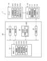
以下、本発明の一実施形態に係る制御装置について図面を参照して説明する。図1は、一実施形態に係るロボット制御システムを構成する制御装置の主要内部構成を概略的に示した機能ブロック図である。図2は、制御の対象となるロボットを模式的に示した外観図である。 A control device according to an embodiment of the present invention will be described below with reference to the drawings. FIG. 1 is a functional block diagram schematically showing the main internal configuration of a control device that constitutes a robot control system according to one embodiment. FIG. 2 is an external view schematically showing a robot to be controlled.
ロボット制御システム1は、ロボット10と、ロボット10の動作を制御する制御装置(ロボット制御装置)20と、を含んで構成される。 The
ロボット10は、図2に示すように、人間の腕と同様の運動機能を持つマニピュレーターで、三次元空間を自在に移動可能なアーム(ロボットアーム)11を備え、アーム11の根元は台座14に固定されている。アーム11は、複数の関節12A乃至12E(以降、まとめて「関節12」とも称す)と、関節12どうしをつなぐリンク13A乃至13Dとを有する。 As shown in FIG. 2, the
また、アーム11は、その先端部15にエンドエフェクターが回動可能に設けられている。具体的には、アーム11の先端部15に設けられた回動機構18(例えば、ステッピングモータ)に、エンドエフェクターが装着されている。 An end effector is rotatably provided at the
図2中では、エンドエフェクターとして、平行に配置された2つの爪部41A,41Bを有するグリッパー41が取り付けられている。グリッパー41は、例えば、テーブル43に載せられたワーク(把持対象物)42を把持して、ワーク42を任意の場所へ運ぶことに使用される。図2中では、回動機構18は、X-Y平面(水平面)内のY軸方向を回動軸18Aとし、この回転軸がワーク42の中心に位置する状態でグリッパー41が回動可能となっている。これにより、ワーク42に働く遠心力で当該ワーク42が滑って外れることを抑制することができる。なお、回動機構18は、その回転軸が、ワーク42の中心に位置する状態とすることがより好ましいが、回動機構18の回転軸が、ワーク42の中心からずれているものの当該ワーク42に位置する状態としてもよい。 In FIG. 2, a
また、グリッパー41には、空気圧により爪部41A,41Bを駆動する爪部駆動部41C(例えば、シリンダー)が内蔵されている。 Further, the
また、グリッパー41には、ワーク42を把持する把持トルク(つまり、爪部41A,41Bによる把持力)を検出する第2検出部(トルク検出部)41Dが設けられている。第2検出部41Dとしては、例えば、トルクセンサーが挙げられる。 Further, the
また、グリッパー41の爪部41A,41Bにおけるワーク42に向く面側には、既知の滑りセンサー41Fがそれぞれ設けられている。この滑りセンサー41Fにより、グリッパー41の爪部41A,41Bが把持するワーク42の滑りを検出することが可能となっている。具体的には、爪部41Aの滑りセンサー41F、及び、爪部41Bの滑りセンサー41Fはそれぞれ、滑り量とその滑り方向とが検出可能であり、各滑りセンサー41Fの検出信号が、ロボット10を介して制御装置20に出力される。 Further, a known slip sensor 41F is provided on each of the
また、グリッパー41には、加速度センサー41Gが設けられている。この加速度センサー41Gにより、重力方向の検出が可能となっている。 Further, the
ロボット10は、関節12それぞれに設けられた、関節12を駆動する駆動部(関節駆動部)16A乃至16E(以降、まとめて「駆動部16」とも称す)と、関節12それぞれに設けられた、関節12の角度を検出する関節角検出部17A乃至17E(以降、まとめて「関節角検出部17」とも称す)と、ロボット10の上方に設けられたカメラ19と、を備える。なお、駆動部16、及び関節角検出部17としてはそれぞれ、例えば、モーター、エンコーダーが挙げられる。 The
また、関節角検出部17は、特許請求の範囲における第1検出部(位置検出部)の一例である。アーム11の先端部15の位置は、関節12A乃至12Eすべての角度から割り出すことができる。なお、ロボット10の全体を撮影するカメラ19を、上記第1検出部として利用することも可能である。 Also, the joint
制御装置20は、制御ユニット21と、操作部22と、表示部23と、記憶部24と、外部インターフェイス部(外部I/F)25と、を備える。 The
操作部22は、キーボード、マウス、タッチパネル等から構成され制御ユニット21にコマンドや文字を入力したり、表示部23における画面上のポインターを操作したりする。表示部23は、制御ユニット21からの応答やデータ結果を表示する。操作部22は、例えば、アーム11の先端部15の目標到達位置(例えば、把持対象物であるワーク42をプレースする位置)の指示入力に用いられる。 The
記憶部24は、HDD(Hard Disk Drive)などの記憶装置であり、制御装置20の動作に必要なプログラムやデータを記憶し、制御パラメーター記憶部243を含む。 The
制御パラメーター記憶部243は、ピッキング動作、後述する回動動作、プレース動作で用いる制御パラメーターが記憶される。 The control
外部インターフェイス部25は、外部装置と接続するためのもので、制御装置20は、外部インターフェイス部25を介して、ロボット10を構成する駆動部16、関節角検出部17、回動機構18、及びカメラ19と接続され、更に、ロボット10を介して、爪部駆動部41C、第2検出部41D、滑りセンサー41F、及び加速度センサー41Gと接続されている。 The
制御ユニット21は、プロセッサー、RAM(Random Access Memory)、ROM(Read Only Memory)、及び専用のハードウェア回路を含んで構成される。プロセッサーは、例えばCPU(Central Processing Unit)、ASIC(Application Specific Integrated Circuit)、MPU(Micro Processing Unit)、GPU(Graphics Processing Unit)等である。制御ユニット21は、制御部(ロボット制御部)211と、物体認識部212と、軌道生成部213と、滑り演算部214と、算出部(角度算出部)215と、を備えている。 The control unit 21 includes a processor, RAM (Random Access Memory), ROM (Read Only Memory), and a dedicated hardware circuit. The processor is, for example, a CPU (Central Processing Unit), an ASIC (Application Specific Integrated Circuit), an MPU (Micro Processing Unit), a GPU (Graphics Processing Unit), or the like. The control unit 21 includes a control section (robot control section) 211 , an
制御ユニット21は、記憶部24に記憶されている制御プログラムに従った上記プロセッサーによる動作により、制御部211、物体認識部212、軌道生成部213、滑り演算部214、及び算出部215として機能する。但し、制御ユニット21等の上記の各構成は、制御ユニット21による制御プログラムに基づく動作によらず、それぞれハードウェア回路により構成することも可能である。以下、特に触れない限り、各実施形態について同様である。 The control unit 21 functions as a
制御部211は、制御装置20の全体的な動作制御を司る。制御部211は、操作部22、表示部23、記憶部24、及び外部インターフェイス部25と接続されており、接続されている上記各構成の動作制御や、各構成との間での信号またはデータの送受信を行う。 The
物体認識部212は、カメラ19で撮影されることによって得られた画像データに基づいて、例えば、パターンマッチングや機械学習による物体認識を行うことで、把持対象物であるワーク42を認識し、当該ワーク42の位置を検出する。この位置は、ピッキング動作の終点となる。 The
軌道生成部213は、物体認識部212で検出されたワーク42の位置(ピッキング動作の終点)に基づいて、現在位置から当該終点までの、アーム11の先端部15の目標軌道を生成する。また、軌道生成部213は、操作部22を介してユーザーから指示された、ワーク42をプレースする位置(プレース動作の終点)に基づいて、ワーク42を把持した位置から当該終点までの、アーム11の先端部15の目標軌道を生成する。なお、軌道の生成には、RRT(Rapidly exploring random tree)など、種々の生成アルゴリズムを適用することができる。 The
滑り演算部214は、爪部41Aの滑りセンサー41Fの検出信号と、爪部41Bの滑りセンサー41Fの検出信号とに基づいて、グリッパー41が把持(ピッキング)しているワーク42の滑り量とその滑り方向とを演算により算出する。 The
具体的には、滑り演算部214は、例えば、図5(A)に示すように、爪部41Aの滑りセンサー41Fの検出信号が示す滑りベクトルSA1(滑り方向がZ方向で第1滑り量SL1となっている)と、爪部41Bの滑りセンサー41Fの検出信号が示す滑りベクトルSA2(滑り方向がZ方向で第1滑り量SL1よりも小さい第2滑り量SL2となっている)との合成ベクトルCV(つまり、ワーク42に働く滑り方向とその滑り量)を算出する。 Specifically, for example, as shown in FIG. ) and the slip vector SA2 indicated by the detection signal of the slip sensor 41F of the
図5(A)に示すように、ワーク42の爪部41A側の滑り量(第1滑り量SL1)と、ワーク42の爪部41B側の滑り量(第2滑り量SL2)とが異なっているため、ワーク42に働く滑り方向は、重力方向と異なる下向き方向となる。具体的には、図5(B)に示すように、滑り演算部214は、ワーク42に働く滑り方向が重力方向となす角度θ1を、次式(1)により算出する。 As shown in FIG. 5A, the amount of slippage of the
角度θ1=Arctan(L/(SL1-SL2)) ・・・ (1)
但し、L:爪部41Aと爪部41Bとの間の距離(ワークの長さとも言える)、SL1:ワーク42の爪部41A側の滑り量(第1滑り量SL1)、SL2:ワーク42の爪部41B側の滑り量(第2滑り量SL2)である。Angle θ1 = Arctan (L/(SL1-SL2)) (1)
However, L: the distance between the
図5(A)、図5(B)中では、滑り演算部214は、ワーク42に働く滑り方向が重力方向(Z方向)となす角度θ1が例えば40°であると算出している。In FIGS. 5(A) and 5(B), the
なお、図5(A)、図5(C)では、グリッパー41の回動を分かりやすく説明するために、爪部41Aのみハッチングを付し、爪部41Bにはハッチングを付していない。 In FIGS. 5A and 5C, only the
算出部215は、滑り演算部214にて検出された滑り方向と重力の逆方向とがなす角度θ2を算出する。具体的には、算出部215は、滑り演算部214にて検出された滑り方向(図5(A)中では重力方向(Z方向)に対して例えば40°の角度の方向)と、グリッパー41の加速度センサー41Gにより検出される重力方向(Z方向のことであり、例えば0°の方向)の逆方向(Z方向とは反対方向のことであり、例えば180°の方向)とがなす角度θ2(つまり、180°-40°=140°)を算出する。 The
なお、本実施形態では、加速度センサー41Gにより検出される重力方向(Z方向)を用いているが、記憶部24に、ロボット10の三次元空間(XYZ座標系空間)におけるZ方向を示す座標データを予め記憶させておき、適宜に記憶部24から重力方向(Z方向)の座標データを読み出して使用する構成とし、加速度センサー41Gを備えない構成としてもよい。 In this embodiment, the gravitational direction (Z direction) detected by the
制御部211は、滑り演算部214にて検出された滑り方向が重力の逆方向に向くように、ワーク42を把持するグリッパー41を、ワーク42の中心位置を回動軸18Aとして、算出部215にて算出された角度(図5(A)中では、140°)だけ回動させ、図5(C)に示すように、グリッパー41を算出部215にて算出された角度(例えば140°)だけ回動させた状態にする。この回動状態では、図5(A)で示したワーク42の滑り方向が重力の逆方向に向く状態となっている。この回動状態では、グリッパー41が把持するワーク42の滑り方向の力と重力とを対抗させることができ、ワーク42の滑りを解消した状態とすることができる場合がある。すなわち、ワーク42の滑りを解消した把持姿勢とすることができることがある。 The
また、回動機構18の回転軸がワーク42の中心に位置する状態でグリッパー41が回動しているため、ワーク42に働く遠心力で当該ワーク42が滑って外れることを抑制することができる。 Further, since the
制御部211は、ワーク42を把持するグリッパー41を、算出部215にて算出された角度だけ回動させた状態において、滑り演算部214にて水平面よりも下向きの滑りが検出されると、グリッパー41の把持トルクを増加させ、当該ワーク42の滑り量がゼロとなったときの第2検出部41Dにて検出されたトルクを、グリッパー41の把持トルクに設定する。 When the
制御部211は、ワーク42を把持するグリッパー41を、前記算出部215にて算出された角度だけ回動させた状態において、上記とは逆に、滑り演算部214にて水平面よりも上向きの滑りが検出されると、グリッパー41の把持トルクを減少させ、当該ワーク42の滑り量がゼロとなったときの第2検出部41Dにて検出されたトルクを維持する。 In a state in which the
制御部211は、ワーク42を把持するグリッパー41を重力方向(Z方向)に加減速動作で駆動させる。 The
制御部211は、軌道生成部213により生成された目標軌道(例えば、目標位置や目標速度、目標加速度等)と、アーム11の先端部15の位置や速度、加速度等とに基づいて、当該先端部15を目標軌道に追従させるように、その時のロボット10の状態に適した制御パラメーターを用いて、駆動部16の駆動を制御する。 Based on the target trajectory (for example, target position, target speed, target acceleration, etc.) generated by the
また、制御部211は、ピッキング動作、後述する回動動作、プレース動作で使用したそれぞれの最新の制御パラメーターを、制御パラメーター記憶部243に記憶させる。 Further, the
次に、制御装置20における制御ユニット21で行われる処理動作について、図3、図4に示したフローチャートに基づいて説明する。なお、この処理動作は、ロボット10のピッキングアンドプレース動作で行われる処理動作である。 Next, processing operations performed by the control unit 21 in the
まず、物体認識部212が、カメラ19で撮影されることによって得られた画像データに基づいて、把持対象物であるワーク42を認識し、当該ワーク42の位置(ピッキング動作の終点)を検出し(S1)、軌道生成部213が、物体認識部212で検出されたワーク42の位置(ピッキング動作の終点)に基づいて、現在位置から当該終点までの、アーム11の先端部15の目標軌道を生成する(S2)。 First, the
続いて、制御部211が、軌道生成部213により生成された目標軌道が示す次の時刻での先端部15の目標位置や目標速度、目標加速度と、ロボット10の関節角検出部17による検出結果から求められる先端部15の位置や速度、加速度との偏差が小さくなるように、制御パラメーターを用いて、駆動部16に対する制御量を決定し、そして駆動部16の駆動を制御する(S3)。 Subsequently, the
制御部211は、S1において物体認識部212が認識したワーク42をグリッパー41の爪部41A,41Bによってピッキング(把持)する(S4)。 The
制御部211は、爪部41Aの滑りセンサー41Fの検出信号と、爪部41Bの滑りセンサー41Fの検出信号とに基づいて、ワーク42の滑りの発生の有無を判定する(S5)。 The
制御部211は、滑りの発生ありと判定した場合には(S5「Yes」)、ワーク42を把持しているグリッパー41が回動可能な高さに位置しているか否かを判定する(S6)。 When the
制御部211は、グリッパー41が回動可能な高さに位置していないと判定した場合には(S6「No」)、ワーク42をプレースした後、グリッパー41の把持トルクを直前の把持トルクよりも大きい値に変更して、再びワーク42をグリッパー41にて把持させる(S7)。 When the
一方、滑り演算部214は、制御部211にてグリッパー41が回動可能な高さに位置していると判定した場合には(S6「Yes」)、爪部41Aの滑りセンサー41Fの検出信号と、爪部41Bの滑りセンサー41Fの検出信号とに基づいて、グリッパー41が把持(ピッキング)しているワーク42の滑り量とその滑り方向とを演算により算出する(S8)。 On the other hand, when the
具体的には、滑り演算部214は、例えば、図5(A)に示すように、爪部41Aの滑りセンサー41Fの検出信号が示す滑りベクトルSA1(滑り方向がZ方向で第1滑り量SL1となっている)と、爪部41Bの滑りセンサー41Fの検出信号が示す滑りベクトルSA2(滑り方向がZ方向で第1滑り量SL1よりも小さい第2滑り量SL2となっている)との合成ベクトルCV(つまり、ワーク42に働く滑り方向とその滑り量)を算出する。図5(B)に示すように合成ベクトルCVの方向が、ワーク42に働く滑り方向であり、合成ベクトルCVの大きさがワーク42の合成滑り量である。図5(A)に示すように、ワーク42の爪部41A側の滑り量(第1滑り量SL1)と、ワーク42の爪部41B側の滑り量(第2滑り量SL2)とが異なっているため、ワーク42に働く滑り方向は、重力方向と異なる下向き方向(図5(A)中では重力方向(Z方向)に対して例えば40°の角度の方向)であることが算出される。 Specifically, for example, as shown in FIG. ) and the slip vector SA2 indicated by the detection signal of the slip sensor 41F of the
算出部215は、滑り演算部214にて検出された滑り方向と重力の逆方向とがなす角度θ2を算出する(S9)。具体的には、算出部215は、滑り演算部214にて検出された滑り方向(図5(A)中では重力方向(Z方向)に対して例えば40°の角度の方向)と、グリッパー41の加速度センサー41Gにより検出される重力方向(Z方向のことであり、例えば0°の方向)の逆方向(Z方向とは反対方向のことであり、例えば180°の方向)とがなす角度θ2(つまり、θ2=180°-40°=140°)を算出する。 The
制御部211は、滑り演算部214にて検出された滑り方向が重力の逆方向に向くように、ワーク42を把持するグリッパー41を、算出部215にて算出された角度(図5(A)中では、140°)だけ回動させ、図5(C)に示すように、グリッパー41を算出部215にて算出された角度(例えば140°)だけ回動させた状態にする(S10)。この回動状態では、図5(A)で示したワーク42の滑り方向が重力の逆方向に向く状態となっている。グリッパー41が把持するワーク42の滑り方向の力と重力とを対抗させることができ、ワーク42の滑りを解消した状態とすることができる場合がある。すなわち、ワーク42の滑りを解消した把持姿勢とすることができることがある。 The
制御部211は、爪部41Aの滑りセンサー41Fの検出信号と、爪部41Bの滑りセンサー41Fの検出信号とに基づいて、回動されたグリッパー41が把持するワーク42の滑りの発生の有無を判定する(S11)。 The
制御部211が、回動されたグリッパー41が把持するワーク42の滑りの発生なしと判定した場合には(S11「No」)、ワーク42の移動動作に進む(S17)。 When the
一方、制御部211が滑りの発生ありと判定した場合には(S11「Yes」)、滑り演算部214は、爪部41Aの滑りセンサー41Fの検出信号と、爪部41Bの滑りセンサー41Fの検出信号とに基づいて、回動されたグリッパー41が把持(ピッキング)しているワーク42の滑り量とその滑り方向とを演算により算出する。 On the other hand, when the
そして、制御部211は、滑り演算部214にて検出された滑り方向が下向きであるか否かを判定する(S12)。すなわち、制御部211は、回動されたグリッパー41が把持しているワーク42の滑り方向が下向きであるか否かを判定する。 Then, the
制御部211は、滑り演算部214にて検出された滑り方向が下向きであると判定した場合には(S12「Yes」)、グリッパー41の把持トルクを増加させ(S13)、当該ワーク42の滑り量がゼロとなったときの第2検出部41Dにて検出されたトルクを、グリッパー41の把持トルクに設定する(S14)。 When the
グリッパー41を、滑り方向が重力の逆方向に向くように回動させた状態において、水平面よりも下向きの滑りが検出される場合は、グリッパー41の回動前及び回動後において同じく下向きの滑りが生じていることから、そもそもグリッパー41の把持トルクが足らなかったと推測できる。例えば、爪部41Aでの滑りベクトルSA1と、爪部41Bでの滑りベクトルSA2とが同じ場合には、ワーク42を180°回動させたとしても、当該180°回動後の状態においてワーク42が重力方向(Z方向)に滑るため、そもそもグリッパー41の把持トルクが足らなかったといえる。このように、グリッパー41の回動後において下向きの滑りが生じている場合には、グリッパー41の把持トルクを増加させ、当該グリッパー41の滑り量がゼロとなったときの第2検出部41Dにて検出されたトルクを、グリッパー41の把持トルクに設定する。これにより、グリッパー41の把持トルクを最適な値に変更することができ、グリッパー41を滑りなく適切に把持することができる。 In a state in which the
一方、制御部211は、滑り演算部214にて検出された滑り方向が下向きでない、つまり、上向きであると判定した場合には(S12「No」)、グリッパー41の把持トルクを減少させ(S15)、当該ワーク42の滑り量がゼロとなったときの第2検出部41Dにて検出されたトルクを維持する(S16)。 On the other hand, when the
グリッパー41を、滑り方向が重力の逆方向に向くように回動させた状態において、水平面よりも上向きの滑りが検出される場合は、グリッパー41の把持トルクが過剰であると推測できる。このように、グリッパー41の回動後において上向きの滑りが生じている場合には、グリッパー41の把持トルクを減少させ、当該グリッパー41の滑り量がゼロとなったときの第2検出部41Dにて検出されたトルクを維持する。これにより、グリッパー41を滑りなく適切に把持することができ、不必要な把持力相当分の電力を削減することができ、省電力化を図ることができる。 When the
S14のあと、S16のあと、S5「No」の場合、又は、S11「No」の場合には、制御部211は、ワーク42を移動させる(S17)。 After S14, after S16, if "No" in S5 or "No" in S11, the
制御部211は、アーム11の先端部15の位置が、ワーク42をプレースする位置(つまり、目標位置)に到達したか否かを判定する(S18)。アーム11の先端部15の位置が目標位置に到達していない場合には(S18「No」)、S17に戻る。 The
一方、アーム11の先端部15の位置が目標位置に到達している場合には(S18「Yes」)、制御部211は、ワーク42を目標位置にプレースさせる(S18)。 On the other hand, when the position of the
具体的には、軌道生成部213は、操作部22を介してユーザーから指示された、ワーク42をプレースする位置(プレース動作の終点)に基づいて、ワーク42を把持した位置から当該終点までの、アーム11の先端部15の目標軌道を生成する。制御部211は、当該目標軌道に従ってワーク42を目標位置にプレースさせる。例えば、制御部211は、回動された状態のグリッパー41を水平姿勢に戻してから、ワーク42を目標位置にプレースさせる。 Specifically, the
そして、制御部211は、引き続きワーク42がある場合には、上記S1~S19の処理を実行させ、ワーク42がない場合には、本処理を終了させる。 Then, if the
上記実施形態によれば、滑り演算部214は、グリッパー41が把持するワーク42の滑り方向(重力方向(Z方向)に対して角度θ1の方向)を検出する。算出部215は、滑り演算部214にて検出された滑り方向と重力の逆方向とがなす角度θ2を算出する。制御部211は、滑り演算部214にて検出された滑り方向が重力の逆方向に向くように、ワーク42を把持するグリッパー41を、算出部215にて算出された角度だけ回動させる。このようにグリッパー41の回動後の状態では、グリッパー41が把持するワーク42の滑り方向の力と重力とを対抗させることができ、ワーク42の滑りを解消した状態とすることができる場合がある。特に、グリッパー41がワーク42に対して複数点支持(例えば2点支持)で把持しているときに、各支持点の滑り量が異なることで当該ワーク42が重力の方向とは異なる方向に滑るような場合には、グリッパー41を、滑り方向が重力の逆方向に向くように回動させることで、滑りを解消した把持姿勢とすることができることがある。これによれば、グリッパー41の把持トルクを増加させることなく、ワーク42が滑り落ちることを低減することができる。このため、ワーク42の対象範囲を拡大することができ、ロバスト性を向上させることができる。また、把持力を増加させないので、把持力の増加による消費電力の増加を抑制でき、省電力化を図ることができる。 According to the above embodiment, the
アーム11の先端部15には、ワーク42を把持するグリッパー41を回動させる回動機構18が設けられている。回動機構18の回動軸18Aは、グリッパー41に把持されたワーク42の中心に位置している。制御部211は、回動機構18の回動軸18Aを回動させることで、グリッパー41に把持されているワーク42の中心に、グリッパー41を回動させる。すなわち、グリッパー41の回動軸18Aが当該ワーク42の中心に位置する状態で当該グリッパー41を回動させる。これにより、ワーク42に働く遠心力を抑えることができ、ワーク42に働く遠心力で当該ワーク42が滑って外れることを抑制することができる。要するに、グリッパー41の回動によってワーク42が滑って外れることを防止できる。 A
また、グリッパー41を、滑り方向が重力の逆方向に向くように回動させた状態において、水平面よりも下向きの滑りが検出される場合は、グリッパー41の回動前及び回動後において同じく下向きの滑りが生じていることから、そもそもグリッパー41の把持トルクが足らなかったと推測できる。このように、グリッパー41の回動後において下向きの滑りが生じている場合には、グリッパー41の把持トルクを増加させ、当該ワーク42の滑り量がゼロとなったときの第2検出部41Dにて検出されたトルクを、グリッパー41の把持トルクに設定する。これにより、グリッパー41の把持トルクを最適な値に変更することができ、ワーク42を滑りなく適切に把持することができる。 In addition, when the
また、グリッパー41を、滑り方向が重力の逆方向に向くように回動させた状態において、水平面よりも上向きの滑りが検出される場合は、グリッパー41の把持トルクが過剰であると推測できる。このように、グリッパー41の回動後において上向きの滑りが生じている場合には、グリッパー41の把持トルクを減少させ、当該ワーク42の滑り量がゼロとなったときの第2検出部41Dにて検出されたトルクを維持する。これにより、ワーク42を滑りなく適切に把持することができ、不必要な把持力相当分の電力を削減することができ、省電力化を図ることができる。 Also, when the
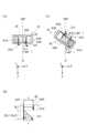
なお、上記実施の形態では、アーム11の先端部15に設けられた回動機構18(例えば、ステッピングモータ)に、エンドエフェクターが装着されているとしているが、これに限定されない。ロボット10は、回動機構18を設けない構成とし、制御部211が、ロボット10の状態に適した制御パラメーターを用いて駆動部16を制御し、関節12を駆動することにより、図6に実線で示すように、グリッパー41を算出部215にて算出された角度(例えば140°)だけ回動させた状態にする構成としてもよい。 In the above embodiment, the end effector is attached to the rotating mechanism 18 (for example, a stepping motor) provided at the
例えば、上記実施の形態と同様に、滑り演算部214は、図7(B)に示すように、ワーク42に働く滑り方向が重力方向となす角度θ1を、次式(1)により算出する。制御部211は、滑り演算部214にて検出された滑り方向が重力の逆方向に向くように、ワーク42を把持するグリッパー41を、ワーク42の中心位置を回動軸18Aとして、算出部215にて算出された角度(図7(A)中では、140°)だけ回動させ、図7(C)に示すように、グリッパー41を算出部215にて算出された角度(例えば140°)だけ回動させた状態にする。この回動状態では、図7(A)で示したワーク42の滑り方向が重力の逆方向に向く状態となっている。この回動状態では、グリッパー41が把持するワーク42の滑り方向の力と重力とを対抗させることができ、ワーク42の滑りを解消した状態とすることができる場合がある。すなわち、ワーク42の滑りを解消した把持姿勢とすることができることがある。 For example, as in the above embodiment, the
なお、上記実施の形態及び変形例では、グリッパー41の爪部41A,41Bにおけるワーク42に向く面側に、滑りセンサー41Fをそれぞれ設けているが、これに限定されない。例えば分布式接触センサーを、滑りセンサー41Fに替えて設けるようにしてもよい。分布式接触センサーはワーク42と爪部41A,41Bの接触領域がわかる。滑り演算部214は、分布式接触センサーからの検出信号(接触領域の時間的な変化を示す信号)に基づいてワーク42の滑り量及び滑り方向を算出する。 In addition, in the above-described embodiment and modified example, slip sensors 41F are provided on the sides of the
本発明は上記実施の形態の構成に限られず種々の変形が可能である。また、上記実施形態では、図1乃至図7を用いて上記実施形態により示した構成及び処理は、本発明の一実施形態に過ぎず、本発明を当該構成及び処理に限定する趣旨ではない。 The present invention is not limited to the configuration of the above embodiment, and various modifications are possible. Also, in the above embodiment, the configuration and processing shown in FIGS. 1 to 7 are merely an embodiment of the present invention, and are not intended to limit the present invention to the configuration and processing.
1 ロボット制御システム
10 ロボット
11 アーム
12 関節
15 先端部
16 駆動部
17 関節角検出部(第1検出部)
18 回動機構
18A 回動軸
19 カメラ
20 制御装置
24 記憶部
41 グリッパー(エンドエフェクター)
41A、41B 爪部
41C 爪部駆動部
41D 第2検出部
41F 滑りセンサー
41G 加速度センサー
42 ワーク(把持対象物)
211 制御部
214 滑り演算部
215 算出部
1
18
41A,
211
Claims (6)
Translated fromJapanese前記複数の関節それぞれに設けられた、前記関節を駆動する駆動部と、
前記アームの先端部に設けられ、把持対象物を両側から把持する2つの爪部を有するエンドエフェクターと、
前記エンドエフェクターの位置を検出する第1検出部と、
前記エンドエフェクターが前記把持対象物を把持するトルクを検出する第2検出部と、を備えるロボットの動作を制御する制御装置であって、
前記2つの爪部にそれぞれ設けられており、把持されている前記把持対象物のそれぞれの爪部での滑り量及び滑り方向を検出する2つの滑りセンサーと、
前記2つの滑りセンサーのうちの一方から出力される滑り量及び滑り方向と、他方から出力される滑り量及び滑り方向とに基づいて、把持されている前記把持対象物に働く滑り量及び滑り方向を算出する滑り演算部と、
前記滑り演算部が算出した前記滑り方向と重力の逆方向とがなす角度を算出する算出部と、
前記滑り演算部が算出する前記滑り方向が重力の逆方向に向くように、前記把持対象物を把持する前記エンドエフェクターを、前記算出部にて算出された角度だけ回動させる制御部と、を備える制御装置。an arm having a plurality of joints and capable of freely moving in a three-dimensional space;
a driving unit provided for each of the plurality of joints for driving the joint;
an end effector provided at the tip of the arm andhaving two claws for gripping an object to be grippedfrom both sides ;
a first detection unit that detects the position of the end effector;
A control device for controlling the operation of a robot, comprising: asecond detection unit that detects torque with which the end effector grips the gripped object;
two slip sensors provided on each of the two claws for detecting a slip amount and a slipping direction of each of the claws of the gripped object;
The slip amount and slip direction acting on the gripped object based on the slip amount and slip direction output from one of the two slip sensors and the slip amount and slip direction output from the other. a slip calculation unit that calculates
acalculation unit that calculates an angle formedby the slip direction calculated by the slip calculation unit and the opposite direction of gravity;
a control unitthat rotates the end effector that grips the object to be gripped by the angle calculated by the calculation unit so thatthe sliding direction calculated by the slip calculation unit is opposite to the direction of gravity. Control device provided.
前記回動機構の回動軸は、前記エンドエフェクターに把持された前記把持対象物の中心に位置しており、
前記制御部は、前記回動機構の回動軸を回動させることで、前記エンドエフェクターに把持されている前記把持対象物の中心に、当該エンドエフェクターを回動させる請求項1乃至請求項5の何れか1つに記載の制御装置。A rotation mechanism for rotating the end effector that grips the gripping object is further provided at the tipof the arm,
The rotation axis of the rotation mechanism is positioned at the center of thegripped object gripped by the end effector,
6. The control unit rotates the rotation shaft of the rotation mechanism to rotate the end effector about thegripped object gripped by the end effector. The control device according to any one of .
Priority Applications (3)
| Application Number | Priority Date | Filing Date | Title |
|---|---|---|---|
| JP2018235633AJP7247572B2 (en) | 2018-12-17 | 2018-12-17 | Control device |
| CN201911275348.0ACN111037553B (en) | 2018-12-17 | 2019-12-12 | control device |
| US16/711,503US11123872B2 (en) | 2018-12-17 | 2019-12-12 | Control apparatus that controls arm for gripping object |
Applications Claiming Priority (1)
| Application Number | Priority Date | Filing Date | Title |
|---|---|---|---|
| JP2018235633AJP7247572B2 (en) | 2018-12-17 | 2018-12-17 | Control device |
Publications (2)
| Publication Number | Publication Date |
|---|---|
| JP2020097073A JP2020097073A (en) | 2020-06-25 |
| JP7247572B2true JP7247572B2 (en) | 2023-03-29 |
Family
ID=70236397
Family Applications (1)
| Application Number | Title | Priority Date | Filing Date |
|---|---|---|---|
| JP2018235633AActiveJP7247572B2 (en) | 2018-12-17 | 2018-12-17 | Control device |
Country Status (3)
| Country | Link |
|---|---|
| US (1) | US11123872B2 (en) |
| JP (1) | JP7247572B2 (en) |
| CN (1) | CN111037553B (en) |
Families Citing this family (4)
| Publication number | Priority date | Publication date | Assignee | Title |
|---|---|---|---|---|
| JP7384898B2 (en)* | 2019-03-13 | 2023-11-21 | 日本電気株式会社 | Information processing device, drive control method, and computer program |
| JP7740248B2 (en)* | 2020-08-20 | 2025-09-17 | ソニーグループ株式会社 | Information processing device, information processing method, and program |
| US11795012B1 (en)* | 2020-11-06 | 2023-10-24 | Aaron Thomas Bacon | Multi-gripper system |
| EP4245483A4 (en)* | 2020-11-10 | 2024-04-24 | Sony Group Corporation | INFORMATION PROCESSING DEVICE, INFORMATION PROCESSING METHOD AND PROGRAM |
Citations (2)
| Publication number | Priority date | Publication date | Assignee | Title |
|---|---|---|---|---|
| JP2003127081A (en) | 2001-10-18 | 2003-05-08 | Ricoh Co Ltd | Assembly robot and method for assembling parts using the assembly robot |
| JP2005177977A (en) | 2003-11-25 | 2005-07-07 | Matsushita Electric Works Ltd | Robot hand control device |
Family Cites Families (24)
| Publication number | Priority date | Publication date | Assignee | Title |
|---|---|---|---|---|
| DE3931753A1 (en)* | 1989-09-22 | 1991-04-04 | Deutsche Forsch Luft Raumfahrt | DEVICE FOR SIMULATING ON THE EARTH OF OPERATIONS OF A MANIPULATOR USED IN SPACE ON A MODEL OF A SPACE VEHICLE |
| JP2793493B2 (en)* | 1993-12-28 | 1998-09-03 | 本田技研工業株式会社 | Robot hand grip control method |
| US7443115B2 (en)* | 2002-10-29 | 2008-10-28 | Matsushita Electric Industrial Co., Ltd. | Apparatus and method for robot handling control |
| WO2008058061A2 (en)* | 2006-11-03 | 2008-05-15 | President And Fellows Of Harvard College | Robust compliant adaptive grasper and method of manufacturing same |
| JP5187552B2 (en)* | 2007-09-13 | 2013-04-24 | ソニー株式会社 | Control device and method, program, and recording medium |
| WO2009094670A1 (en)* | 2008-01-25 | 2009-07-30 | The Trustees Of Columbia University In The City Of New York | Systems and methods for force sensing in a robot |
| US8861171B2 (en)* | 2010-02-10 | 2014-10-14 | Sri International | Electroadhesive handling and manipulation |
| CN101829003B (en)* | 2010-05-18 | 2013-08-14 | 青岛思威机器人科技有限公司 | Exoskeleton-type upper limb rehabilitation robot |
| JP5854695B2 (en)* | 2010-09-22 | 2016-02-09 | キヤノン株式会社 | Robot apparatus control method and robot apparatus |
| JP5588392B2 (en)* | 2011-04-27 | 2014-09-10 | 株式会社日立製作所 | Manipulator device |
| JP2012250298A (en)* | 2011-05-31 | 2012-12-20 | Sony Corp | Robot apparatus and method for controlling the same |
| JP5837065B2 (en)* | 2011-06-29 | 2015-12-24 | 三菱電機株式会社 | Parts supply device |
| JP5895628B2 (en)* | 2012-03-15 | 2016-03-30 | 株式会社ジェイテクト | ROBOT CONTROL METHOD, ROBOT CONTROL DEVICE, AND ROBOT CONTROL SYSTEM |
| JP5629742B2 (en)* | 2012-09-28 | 2014-11-26 | 京セラドキュメントソリューションズ株式会社 | Electronic apparatus and image forming apparatus |
| DE102014009893B4 (en)* | 2014-07-04 | 2016-04-28 | gomtec GmbH | End effector for an instrument |
| JP6075343B2 (en)* | 2014-09-02 | 2017-02-08 | トヨタ自動車株式会社 | Traveling robot, operation planning method thereof, and program |
| CN204390171U (en)* | 2015-01-13 | 2015-06-10 | 张敬辉 | A kind of the back of the hand that is worn over is by the data input control device pointing control |
| CN105751218B (en)* | 2016-05-05 | 2018-05-08 | 佛山市新鹏机器人技术有限公司 | A kind of constant force device and its control method for robot end |
| JP6514156B2 (en)* | 2016-08-17 | 2019-05-15 | ファナック株式会社 | Robot controller |
| JP7289616B2 (en)* | 2017-06-30 | 2023-06-12 | キヤノン株式会社 | ROBOT HAND, ROBOT DEVICE, AND METHOD OF CONTROLLING ROBOT HAND |
| JP6640792B2 (en)* | 2017-06-30 | 2020-02-05 | ファナック株式会社 | Hand control device, hand control method, and hand simulation device |
| US10792809B2 (en)* | 2017-12-12 | 2020-10-06 | X Development Llc | Robot grip detection using non-contact sensors |
| CN108331607B (en)* | 2018-03-23 | 2024-01-16 | 中国矿业大学 | Mine ventilation dust fall automatic control device |
| KR102695661B1 (en)* | 2018-06-22 | 2024-08-19 | 소니그룹주식회사 | Control device, control method and program |
- 2018
- 2018-12-17JPJP2018235633Apatent/JP7247572B2/enactiveActive
- 2019
- 2019-12-12USUS16/711,503patent/US11123872B2/enactiveActive
- 2019-12-12CNCN201911275348.0Apatent/CN111037553B/enactiveActive
Patent Citations (2)
| Publication number | Priority date | Publication date | Assignee | Title |
|---|---|---|---|---|
| JP2003127081A (en) | 2001-10-18 | 2003-05-08 | Ricoh Co Ltd | Assembly robot and method for assembling parts using the assembly robot |
| JP2005177977A (en) | 2003-11-25 | 2005-07-07 | Matsushita Electric Works Ltd | Robot hand control device |
Also Published As
| Publication number | Publication date |
|---|---|
| US11123872B2 (en) | 2021-09-21 |
| CN111037553B (en) | 2022-11-11 |
| JP2020097073A (en) | 2020-06-25 |
| CN111037553A (en) | 2020-04-21 |
| US20200189116A1 (en) | 2020-06-18 |
Similar Documents
| Publication | Publication Date | Title |
|---|---|---|
| JP7247572B2 (en) | Control device | |
| US11090814B2 (en) | Robot control method | |
| JP6912415B2 (en) | Hand control device and hand control system | |
| JP6380828B2 (en) | Robot, robot system, control device, and control method | |
| US10434646B2 (en) | Robot control apparatus, robot, and robot system | |
| US11602863B2 (en) | Device, method and program for estimating weight and position of gravity center of load by using robot | |
| WO2008001713A1 (en) | Articulated robot and its control program | |
| JP2009269127A (en) | Holding device and method of controlling the same | |
| CN111443703B (en) | Track generation device, track generation method, and robot system | |
| CN111721391A (en) | Device, method, and program for estimating weight and center of gravity position of load by robot | |
| JP6696341B2 (en) | Control method | |
| US20160306340A1 (en) | Robot and control device | |
| JP2015071207A (en) | Robot hand and control method thereof | |
| JP4600445B2 (en) | Robot hand device | |
| CN111975764B (en) | Robot device and holding method | |
| KR20200133337A (en) | Control device, control method, and program | |
| JPWO2019065427A1 (en) | Robot hand system control method and robot hand system | |
| JP6322948B2 (en) | Robot control apparatus, robot system, robot, robot control method, and program | |
| JP2017077600A (en) | Manipulator device | |
| JP3328414B2 (en) | Robot hand attitude control device | |
| JP6455869B2 (en) | Robot, robot system, control device, and control method | |
| JP2005144573A (en) | Control method for gripping force of robot hand | |
| WO2022102403A1 (en) | Information processing device, information processing method, and program | |
| JP7159525B2 (en) | ROBOT CONTROL DEVICE, LEARNING DEVICE, AND ROBOT CONTROL SYSTEM | |
| JP2024002787A (en) | Gripping position setting method and robot system |
Legal Events
| Date | Code | Title | Description |
|---|---|---|---|
| A621 | Written request for application examination | Free format text:JAPANESE INTERMEDIATE CODE: A621 Effective date:20211130 | |
| A977 | Report on retrieval | Free format text:JAPANESE INTERMEDIATE CODE: A971007 Effective date:20220922 | |
| RD02 | Notification of acceptance of power of attorney | Free format text:JAPANESE INTERMEDIATE CODE: A7422 Effective date:20220928 | |
| A131 | Notification of reasons for refusal | Free format text:JAPANESE INTERMEDIATE CODE: A131 Effective date:20221011 | |
| A521 | Request for written amendment filed | Free format text:JAPANESE INTERMEDIATE CODE: A523 Effective date:20221205 | |
| TRDD | Decision of grant or rejection written | ||
| A01 | Written decision to grant a patent or to grant a registration (utility model) | Free format text:JAPANESE INTERMEDIATE CODE: A01 Effective date:20230214 | |
| A61 | First payment of annual fees (during grant procedure) | Free format text:JAPANESE INTERMEDIATE CODE: A61 Effective date:20230227 | |
| R150 | Certificate of patent or registration of utility model | Ref document number:7247572 Country of ref document:JP Free format text:JAPANESE INTERMEDIATE CODE: R150 |