JP7247531B2 - Information processing device and program - Google Patents
Information processing device and programDownload PDFInfo
- Publication number
- JP7247531B2 JP7247531B2JP2018215518AJP2018215518AJP7247531B2JP 7247531 B2JP7247531 B2JP 7247531B2JP 2018215518 AJP2018215518 AJP 2018215518AJP 2018215518 AJP2018215518 AJP 2018215518AJP 7247531 B2JP7247531 B2JP 7247531B2
- Authority
- JP
- Japan
- Prior art keywords
- modeling
- cell
- voxels
- physical property
- level
- Prior art date
- Legal status (The legal status is an assumption and is not a legal conclusion. Google has not performed a legal analysis and makes no representation as to the accuracy of the status listed.)
- Active
Links
Images


Classifications
- G—PHYSICS
- G06—COMPUTING OR CALCULATING; COUNTING
- G06F—ELECTRIC DIGITAL DATA PROCESSING
- G06F30/00—Computer-aided design [CAD]
- G06F30/20—Design optimisation, verification or simulation
- G06F30/23—Design optimisation, verification or simulation using finite element methods [FEM] or finite difference methods [FDM]
- B—PERFORMING OPERATIONS; TRANSPORTING
- B29—WORKING OF PLASTICS; WORKING OF SUBSTANCES IN A PLASTIC STATE IN GENERAL
- B29C—SHAPING OR JOINING OF PLASTICS; SHAPING OF MATERIAL IN A PLASTIC STATE, NOT OTHERWISE PROVIDED FOR; AFTER-TREATMENT OF THE SHAPED PRODUCTS, e.g. REPAIRING
- B29C64/00—Additive manufacturing, i.e. manufacturing of three-dimensional [3D] objects by additive deposition, additive agglomeration or additive layering, e.g. by 3D printing, stereolithography or selective laser sintering
- B29C64/30—Auxiliary operations or equipment
- B29C64/386—Data acquisition or data processing for additive manufacturing
- B—PERFORMING OPERATIONS; TRANSPORTING
- B29—WORKING OF PLASTICS; WORKING OF SUBSTANCES IN A PLASTIC STATE IN GENERAL
- B29C—SHAPING OR JOINING OF PLASTICS; SHAPING OF MATERIAL IN A PLASTIC STATE, NOT OTHERWISE PROVIDED FOR; AFTER-TREATMENT OF THE SHAPED PRODUCTS, e.g. REPAIRING
- B29C64/00—Additive manufacturing, i.e. manufacturing of three-dimensional [3D] objects by additive deposition, additive agglomeration or additive layering, e.g. by 3D printing, stereolithography or selective laser sintering
- B29C64/10—Processes of additive manufacturing
- B29C64/106—Processes of additive manufacturing using only liquids or viscous materials, e.g. depositing a continuous bead of viscous material
- B29C64/112—Processes of additive manufacturing using only liquids or viscous materials, e.g. depositing a continuous bead of viscous material using individual droplets, e.g. from jetting heads
- B—PERFORMING OPERATIONS; TRANSPORTING
- B29—WORKING OF PLASTICS; WORKING OF SUBSTANCES IN A PLASTIC STATE IN GENERAL
- B29C—SHAPING OR JOINING OF PLASTICS; SHAPING OF MATERIAL IN A PLASTIC STATE, NOT OTHERWISE PROVIDED FOR; AFTER-TREATMENT OF THE SHAPED PRODUCTS, e.g. REPAIRING
- B29C64/00—Additive manufacturing, i.e. manufacturing of three-dimensional [3D] objects by additive deposition, additive agglomeration or additive layering, e.g. by 3D printing, stereolithography or selective laser sintering
- B29C64/10—Processes of additive manufacturing
- B29C64/106—Processes of additive manufacturing using only liquids or viscous materials, e.g. depositing a continuous bead of viscous material
- B29C64/124—Processes of additive manufacturing using only liquids or viscous materials, e.g. depositing a continuous bead of viscous material using layers of liquid which are selectively solidified
- B29C64/129—Processes of additive manufacturing using only liquids or viscous materials, e.g. depositing a continuous bead of viscous material using layers of liquid which are selectively solidified characterised by the energy source therefor, e.g. by global irradiation combined with a mask
- B29C64/135—Processes of additive manufacturing using only liquids or viscous materials, e.g. depositing a continuous bead of viscous material using layers of liquid which are selectively solidified characterised by the energy source therefor, e.g. by global irradiation combined with a mask the energy source being concentrated, e.g. scanning lasers or focused light sources
- B—PERFORMING OPERATIONS; TRANSPORTING
- B29—WORKING OF PLASTICS; WORKING OF SUBSTANCES IN A PLASTIC STATE IN GENERAL
- B29C—SHAPING OR JOINING OF PLASTICS; SHAPING OF MATERIAL IN A PLASTIC STATE, NOT OTHERWISE PROVIDED FOR; AFTER-TREATMENT OF THE SHAPED PRODUCTS, e.g. REPAIRING
- B29C64/00—Additive manufacturing, i.e. manufacturing of three-dimensional [3D] objects by additive deposition, additive agglomeration or additive layering, e.g. by 3D printing, stereolithography or selective laser sintering
- B29C64/20—Apparatus for additive manufacturing; Details thereof or accessories therefor
- B29C64/264—Arrangements for irradiation
- B29C64/291—Arrangements for irradiation for operating globally, e.g. together with selectively applied activators or inhibitors
- B—PERFORMING OPERATIONS; TRANSPORTING
- B29—WORKING OF PLASTICS; WORKING OF SUBSTANCES IN A PLASTIC STATE IN GENERAL
- B29C—SHAPING OR JOINING OF PLASTICS; SHAPING OF MATERIAL IN A PLASTIC STATE, NOT OTHERWISE PROVIDED FOR; AFTER-TREATMENT OF THE SHAPED PRODUCTS, e.g. REPAIRING
- B29C64/00—Additive manufacturing, i.e. manufacturing of three-dimensional [3D] objects by additive deposition, additive agglomeration or additive layering, e.g. by 3D printing, stereolithography or selective laser sintering
- B29C64/30—Auxiliary operations or equipment
- B29C64/386—Data acquisition or data processing for additive manufacturing
- B29C64/393—Data acquisition or data processing for additive manufacturing for controlling or regulating additive manufacturing processes
- B—PERFORMING OPERATIONS; TRANSPORTING
- B33—ADDITIVE MANUFACTURING TECHNOLOGY
- B33Y—ADDITIVE MANUFACTURING, i.e. MANUFACTURING OF THREE-DIMENSIONAL [3-D] OBJECTS BY ADDITIVE DEPOSITION, ADDITIVE AGGLOMERATION OR ADDITIVE LAYERING, e.g. BY 3-D PRINTING, STEREOLITHOGRAPHY OR SELECTIVE LASER SINTERING
- B33Y50/00—Data acquisition or data processing for additive manufacturing
- G—PHYSICS
- G06—COMPUTING OR CALCULATING; COUNTING
- G06F—ELECTRIC DIGITAL DATA PROCESSING
- G06F30/00—Computer-aided design [CAD]
- G06F30/10—Geometric CAD
- G06F30/17—Mechanical parametric or variational design
- G—PHYSICS
- G06—COMPUTING OR CALCULATING; COUNTING
- G06N—COMPUTING ARRANGEMENTS BASED ON SPECIFIC COMPUTATIONAL MODELS
- G06N5/00—Computing arrangements using knowledge-based models
- G—PHYSICS
- G06—COMPUTING OR CALCULATING; COUNTING
- G06N—COMPUTING ARRANGEMENTS BASED ON SPECIFIC COMPUTATIONAL MODELS
- G06N7/00—Computing arrangements based on specific mathematical models
- B—PERFORMING OPERATIONS; TRANSPORTING
- B33—ADDITIVE MANUFACTURING TECHNOLOGY
- B33Y—ADDITIVE MANUFACTURING, i.e. MANUFACTURING OF THREE-DIMENSIONAL [3-D] OBJECTS BY ADDITIVE DEPOSITION, ADDITIVE AGGLOMERATION OR ADDITIVE LAYERING, e.g. BY 3-D PRINTING, STEREOLITHOGRAPHY OR SELECTIVE LASER SINTERING
- B33Y10/00—Processes of additive manufacturing
- B—PERFORMING OPERATIONS; TRANSPORTING
- B33—ADDITIVE MANUFACTURING TECHNOLOGY
- B33Y—ADDITIVE MANUFACTURING, i.e. MANUFACTURING OF THREE-DIMENSIONAL [3-D] OBJECTS BY ADDITIVE DEPOSITION, ADDITIVE AGGLOMERATION OR ADDITIVE LAYERING, e.g. BY 3-D PRINTING, STEREOLITHOGRAPHY OR SELECTIVE LASER SINTERING
- B33Y50/00—Data acquisition or data processing for additive manufacturing
- B33Y50/02—Data acquisition or data processing for additive manufacturing for controlling or regulating additive manufacturing processes
Landscapes
- Engineering & Computer Science (AREA)
- Physics & Mathematics (AREA)
- Materials Engineering (AREA)
- Chemical & Material Sciences (AREA)
- Manufacturing & Machinery (AREA)
- Theoretical Computer Science (AREA)
- Optics & Photonics (AREA)
- Mechanical Engineering (AREA)
- General Physics & Mathematics (AREA)
- Evolutionary Computation (AREA)
- Geometry (AREA)
- General Engineering & Computer Science (AREA)
- Computer Hardware Design (AREA)
- Data Mining & Analysis (AREA)
- Software Systems (AREA)
- Mathematical Optimization (AREA)
- Mathematical Analysis (AREA)
- Pure & Applied Mathematics (AREA)
- Computational Mathematics (AREA)
- Artificial Intelligence (AREA)
- Mathematical Physics (AREA)
- Computing Systems (AREA)
- Computational Linguistics (AREA)
- Algebra (AREA)
- Health & Medical Sciences (AREA)
- Toxicology (AREA)
Description
Translated fromJapanese本発明は、情報処理装置及びプログラムに関する。 The present invention relates to an information processing apparatus and program.
3Dプリンタ(立体印刷機)等の立体造形装置が普及しつつある。3Dプリンタ用のデータ形式としては、例えばSTL(Standard Triangulated Language)形式や3DS形式のように、立体形状をポリゴンのメッシュ表現で記述する形式が広く用いられている。 Three-dimensional modeling apparatuses such as 3D printers (three-dimensional printers) are becoming popular. As a data format for 3D printers, formats such as the STL (Standard Triangulated Language) format and the 3DS format, which describe three-dimensional shapes in polygon mesh representation, are widely used.
また、出願人等は、3Dプリンタで造形する立体のモデルをボクセル表現で記述する「FAV」というデータ形式を提案している(非特許文献1)。FAV形式は、ボクセルに色、材質、他のボクセルとのリンク強度等の様々な属性を持たせることで、立体形状以外の様々な特性を表現することができる。 In addition, the applicants have proposed a data format called "FAV" for describing a three-dimensional model to be formed by a 3D printer in voxel representation (Non-Patent Document 1). The FAV format can express various characteristics other than a three-dimensional shape by giving voxels various attributes such as color, material, and link strength with other voxels.
特許文献1に開示された材料についてのトポロジーを生成する方法は、コンピュータを使用して材料の1つまたは複数の材料特性をパラメータ化するステップと、パラメータ化するステップは、前記材料を表す繰返し微小構造を限定することにより1つまたは複数の降伏強度、破壊強さ、硬さを含む強度関連の材料特性をパラメータ化するステップと、1つまたは複数の仮想試験を実行するステップとを含み、各仮想試験は異なる微小構造を使用する前記材料に少なくともひとつのフィールドの実際の適用をシミュレートし、パラメータ化に基づいて材料についてのトポロジーを生成するステップと、を含む。 A method of generating a topology for a material disclosed in US Pat. parameterizing one or more strength-related material properties including yield strength, fracture strength, hardness by defining the structure; and performing one or more virtual tests; Virtual testing includes simulating actual application of at least one field to the material using different microstructures and generating a topology for the material based on the parameterization.
個々のボクセルにそれぞれ個別に材料を割り当てることで、単一の材料を用いる場合よりも、造形物の物性値の設計に自由度が得られる。例えば、造形物の領域ごとに個々の材料のボクセルの組合せを変えることで、領域ごとに物性値を異ならせることもできる。このことは、造形物の領域に用いる材料を指定する代わりに物性値を指定する方式での設計が可能になることを意味する。 By individually assigning materials to individual voxels, a greater degree of freedom can be obtained in designing the physical property values of a modeled object than in the case of using a single material. For example, by changing the combination of voxels of individual materials for each region of the modeled object, it is possible to make the physical property values different for each region. This means that it is possible to design by designating physical property values instead of designating materials to be used in the region of the modeled object.
しかし、造形装置で造形可能な造形物を設計するには、造形装置が用いる材料の組合せで実現可能な物性値を指定する必要がある。 However, in order to design a modeled object that can be modeled by a modeling apparatus, it is necessary to specify physical property values that can be achieved by combining materials used by the modeling apparatus.
本発明は、造形物の要素の物性値として造形装置で造形可能な物性値を指定できるよう支援する装置を提供する。 The present invention provides a device that assists in specifying physical property values that can be modeled by a modeling apparatus as physical property values of elements of a modeled object.
請求項1に係る発明は、造形装置の造形の最小単位である造形ボクセルが複数個集まって構成される造形セルごとに、その造形セルを構成する各造形ボクセルがそれぞれ複数の材料のうちのいずれからなるかを特定可能な特定情報と、その造形セルの物性値と、を記憶する記憶手段と、造形物を構成する各領域の材料として前記記憶手段に記憶された造形セルのいずれかの選択を受け付ける選択受付手段と、前記造形物の前記各領域を、当該領域について前記選択受付手段で受け付けた造形セルの集まりに置き換えることで、前記造形物をそれぞれ材料が規定された前記造形ボクセルの集まりとして表す造形可能データを構成する手段と、を含み、前記造形セルごとに、前記造形セルを構成する複数の造形ボクセル同士が結合した状態と、それら造形ボクセルのそれぞれの材料と、が反映された構造解析モデルを用いて、前記造形セルの前記物性値を計算する計算手段を更に含み、前記記憶手段には、前記造形セルごとに、前記計算手段により計算された当該造形セルの前記物性値が記憶される、情報処理装置である。In the invention according to
請求項2に係る発明は、前記選択受付手段は、前記造形セル各々の物性値を示した選択画面を提示する、請求項1に記載の情報処理装置に係る発明である。 The invention according to claim 2 is the information processing apparatus according to
請求項3に係る発明は、前記選択受付手段は、前記領域のサイズからみてミクロ構造のとみなせるサイズ以下のサイズの造形セルを選択肢として示した選択画面を提示する、請求項1又は2に記載の情報処理装置である。 The invention according to claim 3 is the invention according to
請求項4に係る発明は、前記計算手段は、前記構造解析モデルとして、前記造形セルの同一ボクセル層内で互いに隣接する造形ボクセルについて、それら造形ボクセルの材料同士が混じり合った混じり合い領域を含んだモデルを用いて解析する、請求項1に記載の情報処理装置である。In the invention according to claim4 , the calculation means includes, as the structural analysis model, a mixed region in which materials of the shaping voxels are mixed with each other for shaping voxels adjacent to each other in the same voxel layer of the shaping cells. 2. The information processing apparatus according to
請求項5に係る発明は、前記計算手段は、前記構造解析モデルとして、前記造形セル内のボクセル層間又はボクセル行間で互いに隣接する造形ボクセルについて、それら造形ボクセルの材料の組合せに応じた接着状態を示す境界条件を設定したモデルを用いて解析する、請求項1又は4に記載の情報処理装置である。In the invention according to claim5 , the calculation means calculates, as the structural analysis model, adhesion states according to combinations of materials of the shaping voxels for shaping voxels adjacent to each other between voxel layers or between voxel rows in the shaping cells. 5. The information processing apparatus according to
請求項6に係る発明は、前記計算手段は、前記構造解析モデルとして、前記造形セル内の各造形ボクセルについて、当該造形ボクセルの材料と、硬化用エネルギーの照射方向についての深さと、の組合せに応じた硬化度の分布を反映したモデルを用いて解析する、請求項1、4又は5に記載の情報処理装置である。In the invention according to claim6 , the calculation means calculates, as the structural analysis model, for each modeling voxel in the modeling cell, the combination of the material of the modeling voxel and the depth in the irradiation direction of the curing energy. 6. The information processing apparatus according to
請求項7に係る発明は、前記計算手段は、前記造形セルの前記構造解析モデルを用いて均質化解析を行うことで、前記造形セルの物性値を計算する、請求項1、4~6のいずれか1項に記載の情報処理装置である。The invention according to claim7is characterizedin that the calculation means calculates physical property values of the shaping cell by performing homogenization analysis using the structural analysis model of the shaping cell. The information processing apparatus according to any one of the items.
請求項8に係る発明は、前記造形セルには、第1の所定数個の前記造形ボクセルから構成されるレベル1造形セルと、第k(ただしkは2以上の整数)の所定数個のレベル(k-1)造形セルから構成されるレベルk造形セルとがあり、前記計算手段は、前記レベルk造形セルを構成する第kの所定数個のレベル(k-1)造形セルが結合した状態とそれらレベル(k-1)造形セルそれぞれの物性値を反映した構造解析モデルを用いて解析を行うことにより前記レベルk造形セルの物性値を計算する、請求項2~7のいずれか1項に記載の情報処理装置である。In theeighth aspect of the present invention, the modeling cell includes a
請求項9に係る発明は、コンピュータを、造形装置の造形の最小単位である造形ボクセルが複数個集まって構成される造形セルごとに、その造形セルを構成する各造形ボクセルがそれぞれ複数の材料のうちのいずれからなるかを特定可能な特定情報と、その造形セルの物性値と、を記憶する記憶手段、造形物を構成する各領域の材料として前記記憶手段に記憶された造形セルのいずれかの選択を受け付ける選択受付手段、前記造形物の前記各領域を、当該領域について前記選択受付手段で受け付けた造形セルの集まりに置き換えることで、前記造形物をそれぞれ材料が規定された前記造形ボクセルの集まりとして表す造形可能データを構成する手段、として機能させるためのプログラムであって、前記造形セルごとに、前記造形セルを構成する複数の造形ボクセル同士が結合した状態と、それら造形ボクセルのそれぞれの材料と、が反映された構造解析モデルを用いて、前記造形セルの前記物性値を計算する計算手段を更に含み、前記記憶手段には、前記造形セルごとに、前記計算手段により計算された当該造形セルの前記物性値が記憶される、プログラムである。In the invention according to claim9 , the computer is configured such that, for each modeling cell configured by gathering a plurality of modeling voxels, which are the minimum unit of modeling of the modeling apparatus, each of the modeling voxels constituting the modeling cell is made of a plurality of materials. Storage means for storing specific information that can specify which of the above and physical property values of the modeling cell, and modeling cells stored in the storage means as materials for each region that constitutes a modeled object a selection receiving means for receiving a selection of the modeled object, by replacing each region of the modeled object with a group of modeling cells received by the selection accepting means for the region, so that the modeled object is formed of the modeled voxels each having a specified material;A program for functioning as means for composing formable data represented as a set, wherein for each of the forming cells, a state in which a plurality of forming voxels constituting the forming cell are combined, and each of the forming voxels. and calculating means for calculating the physical property values of the modeling cells using a structural analysis model in which materials and materials are reflected. A program in which the physical property values of the modeling cell are stored .
請求項1又は9に係る発明によれば、ユーザが、造形物の要素の物性値として造形装置で造形可能な物性値を指定できるよう支援することができる。更に記憶手段に記憶するセルの物性値として、そのセルを構成するボクセル同士が結合した状態に基づいた物性値を計算することができる。According to the first orninth aspect of the invention, it is possible to assist the user in specifying physical property values that can be modeled by the modeling apparatus as the physical property values of the elements of the modeled object.Furthermore, as the physical property value of the cell stored in the storage means, it is possible to calculate the physical property value based on the state in which the voxels forming the cell are connected.
請求項2に係る発明によれば、ユーザに対し、造形物の領域を構成する造形セルを選ぶ基準となる物性値の情報を提供することができる。 According to the second aspect of the invention, it is possible to provide the user with information on physical property values that serve as criteria for selecting the modeling cells that form the region of the modeled object.
請求項3に係る発明によれば、造形物の各部の物性の再現が粗くなること防ぐことができる。 According to the third aspect of the invention, it is possible to prevent rough reproduction of the physical properties of each part of the modeled object.
請求項7に係る発明によれば、記憶手段に記憶するセルの物性値として、そのセルを構成するボクセル同士が結合した状態に基づいた物性値を計算することができる。According to theseventh aspect of the invention, as the physical property value of the cell stored in the storage means, it is possible to calculate the physical property value based on the state in which the voxels forming the cell are connected.
請求項4に係る発明によれば、記憶手段に記憶するセルの物性値として、隣接ボクセル間の材料の混じり合いの影響を考慮に入れたセルの物性値を計算することができる。According to thefourth aspect of the present invention, it is possible to calculate the physical property value of the cell that takes into consideration the influence of the mixture of materials between adjacent voxels as the physical property value of the cell stored in the storage means.
請求項5に係る発明によれば、記憶手段に記憶するセルの物性値として、ボクセル層間又はボクセル行間での接着状態を考慮に入れたセルの物性値を計算することができる。According to thefifth aspect of the invention, it is possible to calculate, as the physical property values of the cell stored in the storage means, the physical property values of the cell taking into account the state of adhesion between voxel layers or between voxel rows.
請求項6に係る発明によれば、記憶手段に記憶するセルの物性値として、深さに応じた硬化度の分布を考慮に入れたセルの物性値を計算することができる。According to thesixth aspect of the invention, it is possible to calculate, as the physical property values of the cell stored in the storage means, the physical property values of the cell taking into consideration the distribution of the degree of hardening depending on the depth.
請求項8に係る発明によれば、より多くの造形ボクセルから構成される造形セルの物性値を、その造形セルが造形ボクセル単位で構成されているものとして作成した構造解析モデルに基づき計算するよりも、少ない計算処理負荷で計算することができる。According to theeighth aspect of the invention, the physical property values of a modeling cell composed of a larger number of modeling voxels are calculated based on a structural analysis model created assuming that the modeling cell is composed of each modeling voxel. can also be calculated with a small computational load.
<単位セル>
インクジェット方式で造形を行う3Dプリンタでは融けた状態の材料(例えば樹脂)を、形状を構成する対象部位に噴射し、例えば紫外線等の硬化用エネルギーを照射してその材料を硬化させることで造形を行う。造形は層単位で行われ、一層分の造形が完了するごとに次の層の造形が行われる。複数のノズルから物性(例えば強度やヤング率等の機械的性質)の異なる材料を噴射させることで、複数の材料により造形することが可能である。造形対象の物体をボクセル単位で表現するモデルを用い、ボクセルごとにそのボクセルを構成する材料を指定しておく(例えばボクセルの材料属性にその材料の識別名を持たせる)ことで、造形装置はそのモデルに従ってボクセルごとに個別に材料を噴射して造形を行うことが可能になる。以下では、造形される物体のことを造形物と呼び、その造形物をボクセルの集まりで表現したモデルのことを造形物データと呼ぶ。造形物データにおいて、ボクセルごとに材料を指定することで、造形物の各部分ごとにそれぞれ個別に所望の機械的性質を持たせることが可能になる。<Unit cell>
In a 3D printer that uses an inkjet method, a material in a molten state (for example, resin) is sprayed onto a target area that forms a shape, and then irradiated with curing energy such as ultraviolet rays to harden the material. conduct. Modeling is performed layer by layer, and every time one layer is completed, the next layer is modeled. By ejecting materials with different physical properties (for example, mechanical properties such as strength and Young's modulus) from a plurality of nozzles, it is possible to form a model using a plurality of materials. By using a model that expresses the object to be modeled in units of voxels, and specifying the materials that make up the voxels for each voxel (for example, giving the voxel's material attribute an identification name for that material), the modeling apparatus can According to the model, each voxel can be individually sprayed with material for modeling. Hereinafter, an object to be shaped is called a modeled object, and a model representing the modeled object as a collection of voxels is called modeled object data. By designating the material for each voxel in the modeled object data, it is possible to individually give desired mechanical properties to each part of the modeled object.
ここで、噴射され対象部位(すなわちボクセル位置)に付着した材料が硬化するまでにはある程度の時間がかかる。この時間に、その部位の材料が同じ層内の隣の部位に付着した材料と幾分混じり合う。隣り合う材料が同一であれば問題はないが、異なる材料同士である場合、混じり合った部分の物性は元の各々の材料の物性と異なったものとなる。 Here, it takes a certain amount of time for the material that has been sprayed and adhered to the target site (that is, the voxel position) to harden. During this time, the material at that site mixes somewhat with the material deposited at the next site in the same layer. If the adjacent materials are the same, there is no problem, but if they are different materials, the physical properties of the mixed portion will differ from the physical properties of the original materials.
また、一層ごとの造形にはある程度時間がかかるので、ノズルから材料を対象部位に噴射した時点では、その材料の下の層のボクセルの材料は、混じり合いが生じない程度に硬化している。ただし、その硬化した材料とその上に噴射された材料との接着度合いがどの程度になるかは、上下の材料の組合せにより変わってくる。 In addition, since it takes a certain amount of time to form each layer, when the material is sprayed from the nozzle onto the target site, the voxel material in the layer below the material is hardened to the extent that mixing does not occur. However, the degree of adhesion between the cured material and the material sprayed thereon varies depending on the combination of the upper and lower materials.
また、噴射され対象部位に付着した材料には、紫外線等の硬化用エネルギーが照射され、これによりその材料の硬化が促進される。ここで、照射源から発せられた硬化用エネルギーは材料の層の上から照射されるが、材料の表面から深く進むにつれて減衰し、これに応じて硬化作用も減衰する。このため、造形された1つのボクセルの内部でも、深さに応じて硬化度合いが異なることとなる。 In addition, the material that has been sprayed and adhered to the target site is irradiated with curing energy such as ultraviolet rays, thereby accelerating the curing of the material. Here, the curing energy emitted from the irradiation source is irradiated from above the layer of material, but attenuates as it progresses deeper from the surface of the material, and the curing action also attenuates accordingly. For this reason, the degree of hardening varies depending on the depth even inside one shaped voxel.
例えば、ボクセルごとに材料が指定された造形物データをもとに造形物の構造解析を行う場合、上述の各種の事情から、個々のボクセルがそれぞれ対応する材料で均一に構成されていると仮定したのでは、妥当な解析結果が得られない。これに対し、造形物モデルの個々のボクセルについて、上述した隣接ボクセル間での材料の混じり合い、層間での接着度合い、層内での深さに応じた硬化度合いを考慮に入れた構造解析モデルを構成すれば、精度のよい解析が行える。しかし、構造解析モデルが複雑になるため、解析に要する時間が膨大になってしまう。 For example, when performing structural analysis of a modeled object based on modeled object data in which the material is specified for each voxel, it is assumed that each voxel is uniformly composed of the corresponding material due to the various circumstances described above. If you do, you will not get a valid analysis result. On the other hand, for each voxel of the object model, a structural analysis model that takes into account the mixing of materials between adjacent voxels, the degree of adhesion between layers, and the degree of hardening according to the depth within the layer is configured, analysis with high accuracy can be performed. However, since the structural analysis model becomes complicated, the time required for the analysis becomes enormous.
また、造形物データと造形装置とで解像度が異なる場合、すなわち造形物データのボクセルと造形装置のボクセルとのサイズが異なる場合、その造形装置で造形物データが示す造形物を完全に正確に造形できない場合がある。特に造形物データの解像度の方が造形装置の解像度より精細である場合、造形物データ内でボクセルごとに材料が異なる部分はその造形装置では原理上正確に再現できない。なお、造形装置における「ボクセル」とは、その造形装置の造形における最小単位の立体である。 Also, if the object data and the modeling device have different resolutions, that is, if the voxel sizes of the object data and the voxels of the modeling device are different, the modeled object indicated by the object data can be completely and accurately modeled by the modeling device. Sometimes you can't. In particular, when the resolution of the modeled object data is finer than the resolution of the modeling apparatus, the portion of the modeled object data in which the material differs from voxel to voxel cannot be reproduced accurately by the modeling apparatus in principle. A “voxel” in a modeling apparatus is a three-dimensional object that is the minimum unit in modeling by the modeling apparatus.
しかし、互いに近接した複数のボクセルからなる塊を単位とすれば、造形物データ内のその塊の物性(例えば機械的特性)と同等の物性を持つボクセル又はボクセル塊を造形装置で再現することは可能である。すなわち、塊の物性は、その塊を構成する各ボクセルの材料、それらボクセル間での混じり合い、層間の接着、層内での硬化度合いの深さ方向分布からほぼ決まる。造形物データにおけるボクセル塊の物性値を求め、そのボクセル塊を造形装置のボクセルで再現する場合、ボクセル塊としてその物性値と同等の物性値を持つよう個々のボクセルの材料を決めれば、ボクセル塊単位で造形物データの物性を再現した造形物が形成される。 However, if a block consisting of a plurality of voxels that are close to each other is taken as a unit, it is impossible to reproduce a voxel or a voxel block that has the same physical properties (for example, mechanical properties) as the block in the object data. It is possible. In other words, the physical properties of a mass are mostly determined by the material of each voxel that constitutes the mass, the mixture between these voxels, the adhesion between layers, and the distribution of the degree of hardening in the layer in the depth direction. When obtaining the physical property values of a voxel mass in modeled object data and reproducing that voxel mass with the voxels of the modeling device, if the material of each voxel is determined so that the voxel mass has the same physical property value as the voxel mass, the voxel mass A modeled object is formed that reproduces the physical properties of the modeled object data in units.
以上のようないくつかの理由から、この実施形態では、互いに近接する複数のボクセルからなる「単位セル」を導入する。単位セルは、互いに隣接する複数個のボクセルから構成された立方体又は直方体である。例えば、図1に示す互いに隣接する2×2×2(すなわち縦に2個、横に2個、奥行き方向に2個)の合計8個のボクセル10からなる単位セル20が考えられる。この例では単位セル20は、一辺2ボクセルの立方体である。図では、各ボクセルの材料の違いを、図におけるボクセルの色の違いで表現している。 For these reasons, this embodiment introduces a "unit cell" consisting of multiple voxels that are close to each other. A unit cell is a cube or rectangular parallelepiped composed of a plurality of voxels adjacent to each other. For example, the
また、互いに隣接する3×3×3=27個のボクセルからなる単位セルや、4×4×4=64個のボクセルからなる単位セルなど、より大きな単位セルを用いてもよい。ただし、単位セルを構成するボクセル数が多くなるほど、単位セルを構成するボクセルの材料の組合せは多くなるため、組合せ毎に物性値を求めるための計算時間は膨大なものとなっていく。 Also, a larger unit cell such as a unit cell consisting of 3×3×3=27 voxels adjacent to each other or a unit cell consisting of 4×4×4=64 voxels may be used. However, as the number of voxels that form a unit cell increases, the number of combinations of materials for the voxels that form the unit cell increases, so the calculation time required to obtain physical property values for each combination becomes enormous.
本実施形態では、例えば、単位セルを構造解析の単位としたり、造形物データの単位セルを同等の物性値を造形装置の単位セルに置き換えたりすることで、上述の問題に対処する。 In this embodiment, for example, a unit cell is used as a unit for structural analysis, or a unit cell of object data is replaced with a unit cell of a modeling apparatus with equivalent physical property values, thereby addressing the above-described problem.
<単位セルの物性値>
本実施形態の手法では、単位セルの利用のために、実験又はシミュレーション計算又はこれらの組合せにより、単位セルの物性値を求める。単位セルの物性値は、以下の3つの要素の組合せから求める。<Physical property values of unit cell>
In the method of the present embodiment, the physical property values of the unit cell are determined by experiments, simulation calculations, or a combination thereof, in order to use the unit cell. The physical property value of the unit cell is obtained from the combination of the following three elements.
(1)同一層内の隣接ボクセル間の材料の混じり合い
図2の(a)に例示する、同一層内で2つの隣り合うボクセル10a及び10bを考える。2つのボクセル10a及び10bの材料は異なるものとする。また、これら2つのボクセル10を構成する個々の材料は、インクジェットのノズル又はノズル群から、同時に、又は先に噴射された材料が後の材料と混じり合わなくなる程度に硬化するまでの短い時間の間に、それぞれのボクセル位置に噴射されたものとする。(1) Mixing of Materials Between Adjacent Voxels in the Same Layer Consider two
この場合、(b)に示すように、隣り合うボクセル10a及び10bの位置にそれぞれ付着した液状の材料12a及び12bは、互いに接する部分から混じり、混じり合い領域14を形成する。この混じり合い領域14では、材料12a及び12bが混じり合っており、厳密には混じり合いの度合いは場所ごとに異なる。 In this case, as shown in (b), the
このような混じり合いを含む隣接2ボクセルの物性値を求めるために、(c)に示すように、隣接する2つのボクセル10aと10bに対して、中央に混じり合い領域34を設定した構造解析モデル30を構成する。図示例では、構造解析モデル30は、材料12aのみの領域32a、材料12bのみの領域32b、それら両者の間の、両材料が混じり合った混じり合い領域34、の3つの領域から構成される。混じり合い領域34の幅(隣接する2ボクセル10a及び10bの配列方向についての幅)や混じり合い領域34の物性値(強度、ヤング率、ポアソン比等)は、実験又は数値シミュレーションにより求める。 In order to obtain physical property values of two adjacent voxels including such mixture, a structural analysis model in which a
例えば実験の場合は、三次元物体を造形する造形装置(例えば3Dプリンタ)の解像度で異なる材料を例えば同時に隣り合わせに噴射して造形し、その造形結果の微細構造を電子顕微鏡等で観察することで、混じり合い領域を特定する。また、混じり合い領域の強度その他の物性値を測定してもよい。数値シミュレーションの場合は、造形装置の解像度に対応するボクセルのサイズで異なる材料を隣り合わせに造形したときの解析モデルを構成し、この解析モデルをVOF(Volume Of Fluid)法やMPS(Moving Particle Semi- implicit)法等の混相流解析手法を用いて解析することで、混じり合い領域を特定する。そして、このように特定した混じり合い領域の情報から、図2(c)のようにモデル化した場合の混じり合い領域14の幅を決定する。 For example, in the case of experiments, different materials are sprayed side by side at the same time, for example, at the resolution of a modeling device (such as a 3D printer) that models a three-dimensional object, and the fine structure of the modeling result is observed with an electron microscope. , to identify the blended region. Also, the strength and other physical properties of the mixed region may be measured. In the case of numerical simulation, an analysis model is constructed when different materials are formed side by side with a voxel size corresponding to the resolution of the forming device. By analyzing using multiphase flow analysis methods such as the implicit method, the mixing area is identified. Then, the width of the
図示例では、元の材料12a及び12bのみの領域32a及び32bの間、単一の混じり合い領域34を設けたモデルであったが、ボクセル10a及び10bの配列方向に沿って混じり合いの比率が異なる複数の混じり合い領域を設けてもよい。 In the illustrated example, the model provided a
例えば、これら2つのボクセル10a及び10bから構成される1つのセルを考えて、その構造解析モデル30を用いて均質化解析(均質化法とも呼ばれる)を行えば、そのセルが単一の材料で構成されるとみなしたときの物性値が計算できる。均質化解析では、境界条件を設定しつつ構造解析モデルを周期的に配置し、それら周期的に配置された構造解析モデルに対して数値シミュレーションを行うことで、そのモデルが示す構造が示す物性を単一材料で構成した場合の物性値(以下「等価材料物性値」ともいう)を算出する。 For example, considering one cell composed of these two
隣接するボクセル10aと10bの材料が同じである場合、材料同士が混合しても物性値は変わらない。したがって、材料の混合を考慮した構造解析モデル30又はそのモデルに対する均質化解析結果の物性値は、異なる2材料の組合せ毎に生成すればよい。 If the materials of the
図2は、隣接する2ボクセルの場合を示したが、1方向に隣接する3つのボクセル、又は図1に示した単位セル20の1つの層に該当する2×2の4ボクセル等のように、他の配列構成の隣接ボクセル群について、同様の手法で構造解析モデルや等価材料物性値を求めてもよい。 FIG. 2 shows the case of two adjacent voxels, but three voxels adjacent in one direction, or 2×2=4 voxels corresponding to one layer of the
(2)層間の隣接ボクセルの接着
隣接する2つの層の間で隣り合うボクセル同士の接着情報を、実験又は数値シミュレーションで求める。(2) Adhesion of Adjacent Voxels Between Layers Adhesion information between adjacent voxels in two adjacent layers is obtained by experiments or numerical simulations.
実験では、例えば、2つの材料の組合せごとに、第1層の材料の液滴を噴射して硬化させた後、第2層の材料の液滴をその上に噴射し、硬化させてサンプルを形成する。そして、そのサンプルに対して機械的試験を行うことで、層間の剥離強度又は剪断強度あるいはその両方等の接着性評価指標を測定する。 In the experiment, for example, for each combination of two materials, droplets of the material of the first layer were jetted and cured, and then droplets of the material of the second layer were jetted on top and cured to form a sample. Form. Then, the sample is subjected to mechanical tests to measure adhesion evaluation indices such as peel strength and/or shear strength between layers.
数値シミュレーションでは、硬化した第1層の材料とその上に付着して硬化した第2層の材料との接着状態を分子動力学法やナノシミュレーション等の手法で解析し、この解析結果から接着性評価指標を求める。 In the numerical simulation, the state of adhesion between the cured first layer material and the adhered and cured second layer material is analyzed by methods such as molecular dynamics and nano-simulation. Ask for metrics.
上述した同一層内の隣接ボクセル間の材料の混じり合いの解析では、異なる材料の組合せのみを調べたが、層間の隣接ボクセルの接着状態の指標については、同一材料同士についても調べる。 In the analysis of the mixture of materials between adjacent voxels in the same layer described above, only combinations of different materials were examined, but the index of the adhesion state of adjacent voxels between layers is also examined for the same materials.
(3)深さによる硬化度合いの違い
前述のように、材料の硬化度合いは、紫外線等の硬化用エネルギーが当たる表面からの深さ(すなわち硬化用エネルギーの進行方向に沿った距離)によって異なる。そこで、材料ごとに、実験又は数値シミュレーションにより、図3に示すように、ボクセル10の硬化用エネルギー源側の表面から造形の積層方向に沿った深さ範囲毎の硬化度合い、すなわち深さ方向についての硬化度の分布、を求める。(3) Difference in Degree of Curing Due to Depth As described above, the degree of curing of a material varies depending on the depth from the surface irradiated with curing energy such as ultraviolet rays (that is, the distance along the direction in which the curing energy travels). Therefore, for each material, by experiment or numerical simulation, as shown in FIG. Obtain the distribution of the degree of hardening of
例えば、実験により、材料ごとに、硬化用エネルギーの量と硬化度(反応率とも呼ばれる)との関係を、FT-IR(フーリエ変換赤外分光光度計)による赤外スペクトル測定などにより計測する。ボクセル内の表面からの深さごとの硬化エネルギーの量(例えば紫外線の光量)は、ランバート・ベールの法則等に従って求められるので、計測結果と深さごとのエネルギー量から、深さごとの硬化度が求められる。 For example, experimentally, the relationship between the amount of curing energy and the degree of curing (also called reaction rate) is measured for each material by infrared spectrum measurement using an FT-IR (Fourier transform infrared spectrophotometer) or the like. The amount of curing energy (for example, the amount of UV light) for each depth from the surface in the voxel can be obtained according to the Lambert-Beer law, etc. Therefore, from the measurement result and the amount of energy for each depth, the degree of curing for each depth is required.
単位セルの物性値は、単位セルを構成する複数のボクセル同士が結合した状態を示す構造解析モデルを用いて計算する。この構造解析モデルには、上述した3つの要素を反映させる。 A physical property value of a unit cell is calculated using a structural analysis model showing a state in which a plurality of voxels forming the unit cell are connected. This structural analysis model reflects the three elements described above.
例えば、図1に例示した2×2×2のボクセルからなる単位セルの場合を考える。造形装置による層内の造形が1ボクセル幅で進行する方式ならば、その造形の進行方向に沿った2つの隣接するボクセルについて上記(1)の隣接する2ボクセル間での材料の混合を考慮した構造解析モデル(図2の(c))を当てはめる。造形進行方向に隣接する2ボクセルが同一材料の場合は、それら2ボクセルについては同一材料からなる構造解析モデルを当てはめる。合計4つの構造解析モデルの組ができる。更に、この構造解析モデルの組の各ボクセルの領域を、ボクセルの表面からの深さ範囲ごとに細分化する。そして個々のボクセルの各深さ範囲の領域に対して、そのボクセルの材料とその深さ範囲との組合せに対応する硬化度を設定する(上述の(3))。このように細分化された構造解析モデルに対して、更に、層間で隣り合うボクセル同士、及び同一層内の行間で隣り合うボクセル同士のそれぞれについて、それら隣り合うボクセル同士の材料の組合せに応じた接着情報(すなわち、剥離強度や剪断強度等)を境界条件として設定する(上述の(2))。行間で隣接するボクセルのうち前に造形された方は、後の方が造形される時点ではある程度硬化が進んでおり、それらボクセル間では材料の混じり合いは生じないとみなしてよいので、層間で隣接する2つのボクセルと同様に取り扱う。このようにして単位セルの構造解析モデルを構成する。厳密には、硬化度の深さ分布や隣接ボクセル間の接着情報は、隣り合うボクセルの異なる材料の混じり合いの影響を受けるが、混じり合う前の元の材料での値は実用的に問題ない程度の近似値として利用できる。 For example, consider the case of a unit cell consisting of 2×2×2 voxels illustrated in FIG. If the modeling in the layer by the modeling device progresses with a width of 1 voxel, the mixing of materials between two adjacent voxels in (1) above is considered for two adjacent voxels along the direction of progress of the modeling. A structural analysis model (FIG. 2(c)) is applied. If two voxels adjacent to each other in the forming progress direction are made of the same material, a structural analysis model made of the same material is applied to these two voxels. A total of four sets of structural analysis models are created. Furthermore, the region of each voxel in this set of structural analysis models is subdivided for each depth range from the surface of the voxel. Then, for each depth range region of each voxel, the degree of hardening corresponding to the combination of the voxel material and the depth range is set ((3) above). For the structural analysis model subdivided in this way, for each of voxels adjacent between layers and voxels adjacent between rows in the same layer, Adhesion information (ie, peel strength, shear strength, etc.) is set as a boundary condition ((2) above). Of the voxels adjacent to each other between rows, the one formed earlier has already hardened to some extent by the time the voxel formed later is formed, and it can be assumed that the materials do not mix between those voxels. Treat it like two adjacent voxels. Thus, a structural analysis model of the unit cell is constructed. Strictly speaking, the depth distribution of the degree of cure and the adhesion information between adjacent voxels are affected by the mixing of different materials in adjacent voxels, but the values for the original materials before mixing are practically no problem. can be used as an approximation of degree.
このように構成した単位セルの構造解析モデルに対して均質化解析を行うことで、単位セルの等価材料物性値を計算する。 By performing homogenization analysis on the structural analysis model of the unit cell constructed in this way, the equivalent material property values of the unit cell are calculated.
なお、上述のように単位セルのサイズは2×2×2に限らず、例えば3×3×3や5×5×5等のようにより大きいサイズとしてもよいが、そのようにサイズを大きくすると、単位セルの構造解析モデルが複雑なものとなるため、構造解析に要する計算量(例えば計算時間)が膨大になる。 Note that the size of the unit cell is not limited to 2×2×2 as described above, and may be a larger size such as 3×3×3 or 5×5×5. Since the structural analysis model of the unit cell becomes complicated, the amount of calculation (for example, calculation time) required for structural analysis becomes enormous.
<高次セル>
ボクセル群を上に例示した2×2×2の単位セルに置き換えれば、造形物の構成要素の数が約1/8に減る。しかし、これでもまだ構成要素数が多すぎる場合がある。<High order cell>
Replacing the voxel group with the 2×2×2 unit cell exemplified above reduces the number of constituent elements of the object to about 1/8. However, even this may still have too many components.
これに対し、単位セルのサイズを例えば5×5×5や8×8×8等と大きくすれば、造形物の構成要素の数を減らすことができるが、前述したとおり、単位セルのサイズを大きくすると、単位セルの物性値を計算するのに要する計算量が膨大になる。 On the other hand, if the size of the unit cell is increased to, for example, 5×5×5 or 8×8×8, the number of constituent elements of the model can be reduced. If it is made large, the amount of calculation required to calculate the physical property value of the unit cell becomes enormous.
そこで、「高次セル」を導入する。高次セルは、隣接する複数の単位セルからなるセルである。例えば、隣接する2×2×2個の単位セルからなるセルを、レベル1(すなわち1次)セルとする。単位セルは、いわばレベル0(すなわち0次)セルである。同様の規則で、隣接する2×2×2個のレベル1セルからなるレベル2セル、隣接する2×2×2個のレベル2セルからなるレベル3セルというように、再帰的により高レベルのセルを導入してもよい。 Therefore, a "higher-order cell" is introduced. A higher-order cell is a cell composed of a plurality of adjacent unit cells. For example, a cell consisting of 2×2×2 adjacent unit cells is a level 1 (that is, primary) cell. A unit cell is, so to speak, a level 0 (ie 0th order) cell. By a similar rule, a level 2 cell consisting of 2×2×2
レベル1セルの物性値は、それを構成する単位セル群から構成した構造解析モデルを用いて求める。このモデルの各単位セルには、それぞれ当該単位セルの等価材料物性値を設定する。そして、その構造解析モデルに均質化解析を行うことで、レベル1セルの等価材料物性値を求める。同様に、レベルkセル(kは1以上の整数)の物性値は、それを構成するレベル(k-1)セル群から構成した構造解析モデルを用いて均質化解析を行い計算する。 The physical property values of the
なお、造形物データに対して適用するセルのレベルの上限は、その造形物データが表す造形物のサイズに対してセルがミクロ構造とみなせる範囲、すなわちセルが造形物の対応領域に十分多く(すなわちあらかじめ定める閾値以上の個数)繰り返し配置できる範囲内とする。 The upper limit of the cell level applied to object data is the range in which cells can be regarded as a microstructure for the size of the object represented by the object data, that is, the number of cells is sufficiently large in the corresponding area of the object ( That is, the number is equal to or greater than a predetermined threshold value), and is within a range that can be repeatedly arranged.
<解像度変換>
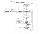
単位セルを利用した造形物データ処理装置100の構成の一例を図4に示す。この例は、造形物データを、造形装置200の解像度のデータ(造形可能データと呼ぶ)に変換する装置である。以下では、造形装置200の解像度で造形物を表現したデータのことを造形可能データと呼ぶ。造形可能データは、造形装置におけるボクセルを単位として造形物を表現する。造形装置200は複数の材料を用いて造形を行うインクジェット方式の3次元造形装置である。造形装置200は、造形に用いる材料ごとに例えば別々のノズルを備え、それらノズルからそれぞれ対応する材料を噴射して造形を行う。なお、造形装置200は、造形物データ処理装置100における解像度変換のターゲットとなる装置であるが、必ずしも図示のように造形物データ処理装置100に接続されていなくてもよい。造形物データ処理装置100は、仮想的な造形装置200をターゲットとして解像度変換を行ってもよい。<Resolution conversion>
FIG. 4 shows an example of the configuration of a modeled object
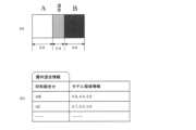
造形物データ処理装置100において、基礎データ記憶部102は、単位セルの物性値を求めるための材料となる基礎データを記憶する。記憶される基礎データには、前述した3つの要素(すなわち層内の材料の混じり合い、層間の接着、深さに応じた硬化情報)のデータが含まれる。3つの要素についての基礎データの例を図5~図7に示す。 In the modeled object
図5には、ボクセル同士の材料の混じり合いを考慮に入れた隣接2ボクセルの構造解析モデルを規定する情報(以下「層内混合情報」と呼ぶ)が例示される。この例では、文字A、B、C、・・・が材料の識別名を示し、2文字からなる文字列AB、AC等が2つの材料の組合せを示す。例えばABは、互いに隣り合う材料Aのボクセルと材料Bのボクセルの組合せを示している。また領域情報は、それら2つのボクセルにおける材料の混ざり合い度合いごとの領域の幅を示す情報である。図示例では、図2と同様、2つのボクセルをその並び方向に沿って、一方の材料のみの領域、両者が均等に混合した領域、他方の材料のみの領域の3つの領域に区分したモデルを想定している。領域情報には、それら各領域の幅を、ボクセルの幅を1としたときの値で示している。この領域情報から、単位ボクセルの構造解析モデルを生成する際の、同一層内の造形の進行方向に沿った領域の区切りと、その領域の物性が決まる。領域の物性は、その領域を構成する材料によって決まる。なお、図5の例では2つのボクセルを3つの領域に分けたが、もっと多くの領域に分けてもよい。 FIG. 5 illustrates information (hereinafter referred to as “intralayer mixture information”) that defines a structural analysis model of two adjacent voxels taking into consideration the mixing of materials between voxels. In this example, letters A, B, C, . For example, AB denotes a combination of material A voxels and material B voxels next to each other. The area information is information indicating the width of the area for each degree of mixture of materials in those two voxels. In the illustrated example, as in FIG. 2, two voxels are divided along the direction of their arrangement into three regions: a region of only one material, a region in which the two are evenly mixed, and a region of only the other material. I assume. The area information indicates the width of each area as a value when the voxel width is 1. Based on this area information, when generating a structural analysis model of a unit voxel, division of areas in the same layer along the progress direction of modeling and physical properties of the areas are determined. The physical properties of a region are determined by the materials that make up the region. Although two voxels are divided into three regions in the example of FIG. 5, they may be divided into more regions.
図6には、層間及び同一層内の行間の接着情報の例が示される。この接着情報には、2つの材料の組合せ(同一材料同士の組合せも含む)ごとに、その組合せに該当するボクセル同士の間の剥離強度、剪断強度等の物性値が示される。 FIG. 6 shows an example of adhesion information between layers and between rows within the same layer. This adhesion information indicates physical property values such as peel strength and shear strength between voxels corresponding to the combination for each combination of two materials (including combinations of the same materials).
図7には、層内の深さに応じた硬化情報が例示される。この硬化情報には、材料ごとに、ボクセルの硬化用エネルギー源からの表面からの各深さ範囲における硬化度の値のリストが示される。 FIG. 7 exemplifies curing information according to the depth in the layer. For each material, this cure information lists cure values at each depth range from the surface from the voxel's curing energy source.
基礎データ記憶部102には、様々な造形装置200で用いられる様々な材料の組合せについて実験等で求めた情報が記憶される。なお、上述した3つの要素の情報は、ボクセルのサイズによって変わることもあり得るので、そのような場合には、異なるいくつかのサイズ範囲毎にそれら3要素の情報を実験等で求め、基礎データ記憶部102に登録しておいてもよい。 The basic
図4の説明に戻る。造形装置情報入力部104は、解像度変換のターゲットである造形装置200の情報の入力を受け付ける。入力される情報には、造形装置200の解像度と、造形装置200が造形に用いる複数の材料を表す情報(例えば材料名のリスト)とが含まれる。 Returning to the description of FIG. The modeling apparatus
セル情報計算部106は、造形装置情報入力部104から入力された造形装置200が用いる材料の情報と、基礎データ記憶部102に記憶された基礎データから、造形装置200が用いる材料により造形可能な単位セルと、それら単位セルから構成可能な高次セルの物性値等の情報を計算する。すなわち、セル情報計算部106は、それら材料から構成可能な単位セルのそれぞれについて、上述の3要素の情報を用いてその単位セルの構造解析モデルを構成し、そのモデルを用いた解析により、それら個々の単位セル(すなわちレベル1セル)の物性値を求める。なお、基礎データ記憶部102が、ボクセルのサイズ範囲ごとに上述の3要素の情報を保持している場合は、セル情報計算部106は、造形装置200の解像度に対応するサイズ範囲の3要素の情報を用いて単位セルの物性値を計算する。 The cell
また、セル情報計算部106は、このように求めた単位セルの情報に基づいて、上述のようにしてそれら単位セルの組合せにより構成可能なすべてのレベル2セルの物性値を求める。また、レベル2セルの情報から、構成可能なすべてのレベル3セルの物性値を計算する。このようにして、使用する可能性のあるレベルまで、高次セルの物性値を求める。求めた単位セル及び高次セルの情報はセル情報DB(データベース)108に保存される。 Based on the unit cell information thus obtained, the
図8に、セル情報DB108に保持されるセル情報の例を示す。図示の例では、レベルごとに、そのレベルに属する各セルのID(すなわち識別情報)に対応付けて、そのセルの物性値と、そのセルを構成する構成要素のリストとが保持される。セルの物性値には、ヤング率、ポアソン比、強度等、1以上の項目の値が含まれる。構成要素のリストは、そのセルを構成する1レベル下のセルのIDが所定の順序で配列したものである。例えば、図1に例示したように、あるレベルのセル(図1の例では単位セル=レベル1セル)が2×2×2の8つの下位セル(図1の例ではボクセル=レベル0セル)から構成される場合、その8つの下位セルに対してあらかじめ定めた順序を設定しておき、それら各下位セルのIDをその順序で並べたものが、上述の構成要素のリストである。なお、レベル0セル(すなわちボクセル)のIDは、材料を識別するIDである。すなわち、4つの材料を用いる造形装置200の場合、レベル0セルは4種類であり、それら4種類を識別するIDをレベル0セルのIDとして用いる。例えばセルID=αの単位セルの構成要素のリストは、材料がそれぞれA、B、C、Dである造形ボクセルを、単位セルを構成する8個のボクセルに対して設定された所定の順序で配列した列「ABCDABCD」である。 FIG. 8 shows an example of cell information held in the
図8では、「レベル1造形セル」等と「造形セル」という名称を用いているが、これは造形装置200の解像度のボクセルから構成されるセル(すなわち単位セル及び各レベルの高次セル)であることを示す。解像度変換の対象である造形物データについても、ボクセル(このボクセルは、造形装置200のボクセルと同サイズとは限らない)を元に単位セルや高次セルを構成するので、これと区別するために造形装置200のボクセルに基づくセルを「造形セル」と呼び分ける。これに対して、造形物データのボクセルに基づくセルを「データセル」と呼ぶこととする。 In FIG. 8, names such as "
以上では、ターゲットとなる造形装置200の情報からセル情報計算部106が基礎データ記憶部102内の情報を用いて動的に各レベルの造形セルの情報を求めたが、これは一例に過ぎない。この代わりに造形装置200の機種ごとに、その機種についての造形セルの情報をあらかじめ求め、その情報を機種IDに対応付けてセル情報DB108に登録しておいてもよい。 In the above description, the cell
図4の説明に戻ると、造形物データ入力部110は、解像度変換の対象である造形物データの入力を受け付ける。造形物データは、ネットワーク経由で、或いは可搬型の記録媒体に記録された状態で、造形物データ入力部110に入力される。 Returning to the description of FIG. 4, the modeled object
セル置換部112は、造形物データのボクセル又はこれらボクセルから構成される単位セル又は高次セル(すなわちデータセル)を、造形セルに置換する。これにより、造形物データは、造形物を造形セルの集まりで表現したものとなる。 The
解像度変換部114は、造形物データを構成する個々の造形セルを、造形装置200のボクセルの集まりに変換する。これにより、造形物データは、造形装置200の解像度のデータとなる。解像度変換部114の変換結果は、造形装置200に入力される。 The
以上、造形物データ処理装置100の構成の一例を説明した。次に、この装置が行う処理の例を説明する。 An example of the configuration of the modeled object
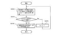
図9は、造形物データ処理装置100が行う全体的な処理の手順を例示する。この手順では、まず造形物データ処理装置100は、処理の対象となる造形物データを取得する(S10)。次に、セル置換部112により、ボクセルの集まりとして表現されている造形物データの各部を単位セル又は高次セルに置換する(S100)。そして、その置換結果のデータに対して、応用処理を実行する(S200)。解像度変換部114が行う解像度変換処理は、応用処理(S200)の一例である。 FIG. 9 illustrates the overall processing procedure performed by the modeled object
次に、図10及び図11を参照して、応用処理(S200)の一例である解像度変換のためのセル置換処理(S100)の手順の例を説明する。この手順は、入力された造形物データに対して解像度変換を必要とする処理(例えば造形装置200への出力)が指示された場合に実行される。造形物データには、当該データの解像度の情報が含まれている。解像度の情報から、造形物データにおけるボクセル(以下「データボクセル」と呼ぶ)のサイズがわかる。各レベルのセル(すなわち単位セル、及びレベル2、3、4・・・の高次セル)は、1レベル下位のセルを例えば2×2×2個で構成する、というようにセルの構成規則が決まっているので、データボクセルのサイズが分かれば、各レベルのセルのサイズも計算できる。 Next, an example of a procedure of cell replacement processing (S100) for resolution conversion, which is an example of the application processing (S200), will be described with reference to FIGS. 10 and 11. FIG. This procedure is executed when a process (for example, output to the modeling apparatus 200) that requires resolution conversion of the input modeled object data is instructed. The modeled object data includes information on the resolution of the data. From the resolution information, the size of voxels (hereinafter referred to as "data voxels") in the object data can be known. Cells at each level (that is, unit cells and higher-order cells at levels 2, 3, 4, . is fixed, so if we know the size of the data voxels, we can also calculate the size of the cells at each level.
この手順では、セル置換部112は、まず造形装置情報入力部104から、造形装置200の造形ボクセルのサイズの情報を取得する(S102)。そして、データボクセルと、造形ボクセルとのサイズを比較する(S104)。データボクセルが造形ボクセル以上の大きさである場合、セル置換部112は、造形ボクセルから構成される各レベルの造形セルのうち、データボクセルと同サイズになる造形セルのレベルk(kは1以上の整数)を求める(S106)。また、ここで説明を簡単にするために、本来はレベル0であるデータボクセルのレベルをkとみなす(S108)。 In this procedure, the
次にセル置換部112は、造形物データを構成するレベルkデータセル(これは最初の処理ループではデータボクセルそのもの)のそれぞれについて、当該レベルkデータセルの物性値と同じ物性値を持つレベルkの造形セルをセル情報DB106から探す(S110)。セル置換部112は、造形物データをレベルkデータセルのサイズごとに分割し、これにより得られた各レベルkデータセルについて、S110の処理を行う。 Next, the
ここで、レベルkデータセルの物性値は、造形物データの各データボクセルに材料名が設定されている場合は、セル情報計算部106により、上述した造形セルの単位セル、及び各レベルの高次セルの場合と同様の方法で計算すればよい。この場合、基礎データ記憶部102に層内混合情報(図5参照)等の3要素の基礎データがボクセルのサイズ範囲毎に用意されていれば、データボクセルのサイズに対応する基礎データを用いて各レベルのデータセルの属性値を計算する。また、データボクセルに材料名の代わりに物性値が設定されている場合、各ボクセルの物性値を用いて、上述した造形セルの単位セル、及び各レベルの高次セルの場合と同様の方法で計算すればよい。 Here, when a material name is set for each data voxel of the object data, the cell
S110では、レベルkデータセルと完全に同じ物性値を持つレベルk造形セルがない場合は、許容範囲内で最も近い物性値を持つレベルk造形セルを、同等の物性値を持つものとして探す。例えば強度、ヤング率、ポアソン比等の個々の物性値の項目ごとに許容範囲を定めておき、全ての項目についてレベルkデータセルの物性値から許容範囲内の物性値を持つレベルk造形セルを抽出し、抽出した中から最もレベルkデータセルの物性値に近い物性値を持つものを特定する。なお、レベルkデータセルの物性値から許容範囲内の物性値を持つレベルk造形セルが見つからなかった場合は、そのレベルkデータセルは造形セルに置換できない。 At S110, if there is no level k build cell with exactly the same physical property value as the level k data cell, then the level k build cell with the closest physical property value within the allowable range is searched as having equivalent physical property values. For example, set the allowable range for each item of individual physical property values such as strength, Young's modulus, Poisson's ratio, etc., and create a level k modeling cell with physical property values within the allowable range from the physical property values of the level k data cell for all items. Among the extracted cells, those having physical property values closest to the physical property values of the level k data cell are specified. If no level k modeling cell having a physical property value within the allowable range is found from the physical property value of the level k data cell, the level k data cell cannot be replaced with the modeling cell.
次にセル置換部112は、S110にて、造形物データを構成する全てのレベルkデータセルに対して、同等の物性値を持つレベルk造形セルが見つかったかどうかを判定する(S112)。この判定の結果がNoの場合、造形物データをレベル(k+1)データセルのサイズごとに分割し(すなわち、造形物内の隣り合うレベルkデータセル群からレベル(k+1)データセルを構成し)、セル情報計算部106により各レベル(k+1)データセルの物性値を計算する(S114)。そして、レベル数kを1増加させて(S116)、S110の処理に戻る。 Next, in S110, the
S112の判定の結果がYesの場合、セル置換部112は、各レベルkデータセルを、それぞれ見つかった同等の物性値を持つレベルk造形セルに置き換える(S118)。すなわち、造形物データを構成する各レベルkデータセルに対して、置換先のレベルk造形セルのIDを対応付ける。これで、セル置換部112の処理は終了する。 If the determination result in S112 is Yes, the
S104の判定結果がNoの場合、セル置換部112は、図11に示すように、造形ボクセルと同サイズとなるデータセルのレベルkを求める(S120)。次に造形物データをレベルkデータセルのサイズごとに分割し(S122)、セル情報計算部106によりそれら各レベルkデータセルの物性値を計算する(S124)。セル置換部112は、造形ボクセルをレベルk造形セルとみなし、セル情報DB108内の造形セルの各レベルmを、レベル(k+m)に読み替える(S126)。 If the determination result in S104 is No, the
次にセル置換部112は、造形物データを構成するレベルkデータセルのそれぞれについて、当該レベルkデータセルの物性値と同等の物性値を持つレベルkの造形セルをセル情報DB108から探す(S128)。S128にて、造形物データを構成する全てのレベルkデータセルに対して、同等の物性値を持つレベルk造形セルが見つかったかどうかを判定する(S130)。この判定の結果がNoの場合、造形物データをレベル(k+1)データセルのサイズごとに分割し、セル情報計算部106により各レベル(k+1)データセルの物性値を計算する(S132)。そして、レベル数kを1増加させて(S134)、S128の処理に戻る。 Next, the
S130の判定の結果がYesの場合、セル置換部112は、各レベルkデータセルを、それぞれ見つかった同等の物性値を持つレベルk造形セルに置き換える(S136)。これで、セル置換部112の処理は終了する。 If the determination result of S130 is Yes, the
S136の置換により、元々データボクセルから構成されていた造形物データの各部分が、同等の物性値を持つ造形ボクセル由来の造形セルに置き換えられる。 By the replacement in S136, each part of the modeled object data originally composed of data voxels is replaced with a modeling cell derived from the modeling voxel having the same physical property value.
図10のS106ではデータボクセルと同サイズとなる造形セルのレベルkを求め、図11のS120では造形ボクセルと同サイズとなるデータセルのレベルkを求めた。しかし、例えばデータボクセルのサイズ、すなわち一辺の長さが造形ボクセルのそれの1.5倍である場合には、レベル1造形セルのサイズの長さは造形ボクセルの2倍となり、データボクセルのサイズと無視できない差がある。このように、データボクセルと造形ボクセルのサイズ関係によっては、S106及びS120の処理が実行できない場合がある。このような場合を考慮して、S106及びS120を以下のように改良してもよい。 In S106 of FIG. 10, the level k of the modeling cell having the same size as the data voxel is obtained, and in S120 of FIG. 11, the level k of the data cell having the same size as the modeling voxel is obtained. However, if, for example, the size of the data voxel, i.e., the length of one side is 1.5 times that of the build voxel, then the length of the
すなわち、この例では、データボクセルと造形ボクセルの一辺の長さの最小公倍数のサイズを求める。そして、データボクセル及び造形セルのそれぞれについて、この最小公倍数のサイズを持つ単位セルを構成する。例えばデータボクセルと造形ボクセルの一辺の長さの比が3:2である場合、造形ボクセルの一辺の長さを1としたときに長さ6が最小公倍数として求められる。この場合、データボクセルについては2×2×2個のボクセルで単位セルを構成し、造形セルについては3×3×3個のボクセルで単位セルを構成する。なお、高次セルについては、データセルも造形セルも、例えばレベルkセルを2×2×2個でレベル(k+1)セルを構成する等、同じルールで構成する。このように、S106及びS120の代わりに、データボクセル側と造形ボクセル側とで単位セルのサイズを一致させる処理を行えばよい。この場合、データ及び造形のそれぞれの単位セルについて、セル情報計算部106により物性値を計算し、高次セルについても物性値を計算する。なお、基礎データ記憶部102には、単位セルの一辺が2、3、5ボクセル等といったいくつかのサイズについて、基礎データ(特に層内混合情報(図5))を用意しておく。 That is, in this example, the size of the least common multiple of the lengths of the sides of the data voxels and the modeling voxels is obtained. Then, for each of the data voxels and modeling cells, a unit cell having the size of this lowest common multiple is constructed. For example, when the ratio of the length of one side of the data voxel to that of the modeling voxel is 3:2, the length 6 is obtained as the least common multiple when the length of one side of the modeling voxel is 1. In this case, 2×2×2 voxels form a unit cell for data voxels, and 3×3×3 voxels form a unit cell for modeling cells. As for higher-order cells, data cells and modeling cells are configured according to the same rule, for example, level (k+1) cells are configured by 2×2×2 level k cells. In this way, instead of S106 and S120, a process of matching the size of the unit cell between the data voxel side and the modeling voxel side may be performed. In this case, the cell
次に、造形物データ処理装置100が行う応用処理(すなわち図9のS200)の一例として、解像度変換部114による解像度変換処理の例を、図12を参照して説明する。 Next, an example of resolution conversion processing by the
図12の手順では、解像度変換部114は、セル置換部112から入力された造形物データを受け取る。この造形物データは、造形物をレベルk造形セルの集まりで表現したデータとなっている。解像度変換部114は、その造形物データを構成する各レベルk造形セルを、それぞれ1レベル下のレベル(k-1)造形セルに分解する(S202)。この分解処理では、セル情報DB108内にあるレベルk造形セルの情報を読み出す。そして、レベルk造形セルを、その情報に含まれる「構成要素」のリスト(図8参照)に示される各レベル(k-1)セルを所定の順序で並べたものに置き換える。 In the procedure of FIG. 12 , the
次に解像度変換部114は、S202の分解によりレベル0、すなわち造形ボクセルのレベルに到達したかどうかを判定し(S204)、到達していなければ、kを1つ減らして(S206)、S202の処理に戻る。S204の判定結果がYesの場合は、S202での分解(下位セルへの置換)後の造形物データは造形ボクセルの集まりとして表現されたものとなっている。すなわち、この造形物データは、造形装置200の解像度で造形物を表現したものとなっており、これを「造形可能データ」と呼ぶ。解像度変換部114は、この造形可能データを造形装置200に出力する(S208)。造形装置200は、この造形可能データに従って、造形物を造形する。 Next, the
<物性値バリエーションを増やす>
造形装置200が例えば物性値の異なるm種類(mは2以上の整数)の材料を用いて造形を行うものである場合、単純に考えるとm種の物性値しか実現できない。ここで、mより多いn種の物性値のバリエーションを持つボクセル群からなる造形物データが入力された場合、上述した単純な考えでは造形できない。この例では、このように造形物データの各部の物性値のバリエーションが造形装置200の用いる材料群の物性値のバリエーションよりも多い場合でも、造形物データが表す造形物を高精度に造形できるようにするためのデータ変換手法を提案する。<Increase variations in physical properties>
For example, if the
この例のための造形物データ処理装置100の装置構成は、図4に示したものと同様でよい。この例では、セル置換部112が図13に例示する処理を実行する。 The device configuration of the modeled object
すなわち、セル置換部112は、まず制御変数kを1に初期化する(S140)。次に、セル置換部112は、造形物データをレベルkデータセルごとに分割し(S142)、分割結果の各レベルkデータセルの物性値をセル情報計算部106に計算させる(S144)。この計算は、図10のS114における物性値の計算と同様の方法で行えばよい。 That is, the
次にセル置換部112は、セル情報DB108から、レベルkの各造形セルの物性値を読み出す(S144)。ここでのレベルk造形セルは、レベルkデータセルと同じサイズの造形セルである。造形ボクセルとデータボクセルのサイズが異なる場合、レベルkデータセルと同じサイズの造形セルのレベルがkとなるよう、セル情報DB108に保持された造形セルのレベルを読み替える。 Next, the
そしてセル置換部112は、造形物データを構成する全てのレベルkデータセルについて、そのセルの物性値と同等の物性値を持つレベルk造形セルがあるかどうかを判定する(S146)。この判定の結果がNoの場合、レベルkの粒度では造形物データの各部分の物性値を造形装置200の材料の組合せで表現できない。そこで、セル置換部112は、レベルを1上げて(すなわちkを1増加させて)(S147)、再度S142~S146の処理を行う。レベルを上げることで造形セルのサイズが大きくなるので、造形セルを構成する材料の組合せが増える。これにより、造形セルの物性値のバリエーションが増えるため、造形物データの各部の物性値と同等の物性値を持つ造形セルが見つかる確率が上がる。 Then, the
このようにしてS142~S147の処理ループを繰り返し、S146の判定がYesになった場合、セル置換部112は、造形物データのレベルkデータセルのそれぞれを、同等の物性値を持つレベルk造形セルに置換する(S148)。これにより、造形物をレベルk造形セルの集まりで表現した造形物データが得られる。この造形物データは、解像度変換部114に入力される。 In this way, the processing loop of S142 to S147 is repeated, and when the determination in S146 becomes Yes, the
解像度変換部114は、この造形物データを図12の処理により造形ボクセル単位の造形可能データへと変換する。これにより、元の造形物データの各部分の物性値を、造形装置200が用いる材料からなる造形ボクセルの組合せでおおよそ表現した造形可能データが完成する。完成した造形可能データは、造形装置200に供給される。 The
<造形物の構造解析>
次に、造形物データの構造解析の負荷軽減のために、造形物データを構成するボクセル群を単位セル又は高次セルに置換する例を説明する。<Structural analysis of molded objects>
Next, an example of replacing a voxel group forming object data with a unit cell or a higher-order cell in order to reduce the load of structural analysis of object data will be described.
図14に、この例に係る造形物データ処理装置100の機能構成を例示する。この造形物データ処理装置100は、図4の例における解像度変換部114の代わりに、モデル構成部116を有する。モデル構成部116は、セル置換部112aが生成したレベルkセル単位の造形物データから、構造解析用のモデル(例えば有限要素法による解析のためのモデル)を構成する。 FIG. 14 illustrates the functional configuration of the modeled object
セル置換部112aは、造形物データ入力部110から入力された造形物データのボクセル群を単位セル又は高次セルに置換することで、造形物データの要素(すなわちデータセル)の数をボクセル単位の場合よりも大幅に少なくする。ボクセル単位だと造形物データの構成要素数が非常の多く、構成要素単位での材料の割り当てとそれら要素の配置の組合せが膨大なものとなってしまい、構造解析モデルが大規模化してしまう。そこで、この例では、造形物データをボクセル単位からよりサイズの大きい単位セルまたは高次セル単位に変換してから構造解析モデルを構成することで、構造解析モデルの規模を抑制する。 The
セル置換部112aが実行する処理手順の例を図15に示す。 FIG. 15 shows an example of the processing procedure executed by the
この処理では、セル置換部112aは、対象となる造形物データを、均一な物性値の領域ごとに分割する(S150)。例えば造形物データの各データボクセルに物性値が設定されている場合は、その造形物データを、同じ物性値を持つ複数の領域に分割する。この場合、個々の領域は、例えば、完全に同じ物性値を持つボクセルの集まりである。また、このように物性値の完全同一を要件とせずに、物性値が所定のばらつき(例えば分散値)以下で同一とみなせるボクセルの集まりを1つの領域としてもよい。また造形物データの各ボクセルに材料が設定されている場合は、例えば同一材料のボクセルが連結した部分を1つの領域としてもよい。また同一材料に限定せず、複数の材料からなる同じ組合せが周期的に繰り返されている範囲を1つの領域としてもよい。この場合、領域の物性値は、その繰り返される材料の組合せを1つの単位として、単位セルの物性値を求めるのと同じ方法で求めればよい。これらの領域は、レベルkセルが後述するミクロ構造の要件を満たすかどうかの判断に用いる。 In this process, the
次にセル置換部112aは、制御変数kを1に初期化し(S152)、造形物データの各領域につき、その領域を埋めるレベルkデータセル(最初のループでは単位セルと等しい)の数を求め、その数が閾値以上かどうかを判定する(S154)。この判定は、レベルkデータセルが個々の領域にとってミクロ構造とみなせる(すなわち当該セルが領域に対して十分小さく、そのセル自体の内部構造を考慮しなくても問題ないとみなせる)サイズかどうかを判定するものである。レベルkデータセルが領域内に十分多くの数だけ繰り返し配置できれば、そのセルはその領域にとってミクロ構造とみなせる。造形物データを構成する全ての領域にとってレベルkデータセルがミクロ構造とみなせれば、その造形物データをボクセル単位の表現からレベルkデータセルを単位とする表現に変換しても、構造解析上大きな問題は起こらない。S154の判定の対象である領域を埋めるレベルkデータセルの数は、三次元であるその領域に配置されるレベルkデータセルの総数であってもよい。また、その数は、その領域の縦、横、奥行きの3方向のそれぞれについてのレベルkデータセルを配置できる個数から求めた代表値であってもよい。その代表値としては、例えば方向ごとのセルの配置可能個数の代表値(例えば平均値、最大値、最小値等)を、3つの方向について平均したものを用いてもよいし、それら各方向の代表値のうちの最大値等といった平均値以外の代表値を用いてもよい。 Next, the
S154の判定の結果がYesの場合、セル置換部112aはkを1増加させ(S156)、再度S154の判定を行う。すなわち、この場合、更に1レベル大きなデータセルが造形物にとってミクロ構造とみなせるかどうかを判定する。 If the determination result of S154 is Yes, the
S154とS156のループを繰り返すことで、造形物にとってミクロ構造とみなせるデータセルの最高レベルが特定される。すなわち、S154の判定結果がNoとなった場合、その時点のレベルkデータセルは造形物データにとってミクロ構造とみなせないので、その1つ前のレベル(k-1)がミクロ構造とみなせる最高レベルである。セル置換部112aは、造形物データを、レベル(k-1)データセル単位のデータに変換する(S158)。すなわち、造形物データの各領域を、その領域の物性値と同等の物性値を持つレベル(k-1)データセルに置き換える。レベル(k-1)のデータセルは十分多くのデータボクセルから構成され、表現できる物性値のバリエーションが多いので、各領域の物性値を表現できるレベル(k-1)データセルは通常見つかる。ただし、念のため、レベル(k-1)データセルが表現可能な物性値のバリエーションをセル情報計算部106により計算し、それらバリエーションの中に各領域の物性値と同等のものがあるかどうかを確認してもよい。そして、もしそのバリエーションで表現できない物性値を持つ領域があれば、S158の置換処理を中止し、ユーザにその旨を通知してもよい。 By repeating the loop of S154 and S156, the highest level of data cells that can be considered microstructures for the model is identified. That is, if the determination result in S154 is No, the level k data cell at that time cannot be regarded as a microstructure for the object data, so the level (k-1) immediately before that is the highest level that can be regarded as a microstructure. is. The
セル置換部112aは、S158の置換結果の造形物データをモデル構成部116に出力する。 The
モデル構成部116は、セル置換部112aから受け取った造形物データに対して、応用処理(すなわち図9のS200)の1つとして、構造解析モデルへの変換を行う。すなわちモデル構成部116は、受け取った造形物データのデータセル単位の構造と各データセルの物性値から、公知の手法により、その造形物データについて有限要素法等の構造解析のためのモデルを構成する。隣接ボクセル間の材料の混じり合い、層間等のボクセル同士の接着、深さ方向の硬化度合いの分布等の要素は単位セルの物性値の計算に織り込んであるので、ここで構成される構造解析モデルにはそれら細部の要素を反映させなくてよい。 The
そして、構成した構造解析モデルを解析装置300に出力する。解析装置300は、その構造解析モデルを用いて構造解析の計算を行う。データセル群から構成したその構造解析モデルは、ボクセル単位の造形物データから構成した構造解析モデルよりも構造要素数が少なく、また隣接ボクセル間の材料の混じり合い等の細部の要素についての解析を行わなくてよい。 Then, the constructed structural analysis model is output to the
図15の手順では、造形物データのボクセルを単位として構成したレベルkセルを用いていたが、これは一例に過ぎない。造形物データを造形する造形装置を想定する場合、造形装置のボクセルサイズと、造形装置が造形に用いる材料のリストと、に基づいて構成したレベルkセルを用いてもよい。この場合、各レベルkセルのサイズは造形ボクセルのサイズを基準に定められる。また、S158で置換に用いるレベル(k-1)セルが決まった場合に、レベル(k-1)セルが取り得る物性値のバリエーションは、その材料のリストに基づいて求められる。すなわち、材料の情報から上述の手法で各単位セルの物性値が計算され、以降下位のレベルから順に、そのレベルに属する各造形セルの物性値が、1つ下のレベルの構成要素のセルの物性値から計算される。 In the procedure of FIG. 15, level k-cells configured in units of voxels of object data are used, but this is merely an example. When assuming a modeling apparatus that models object data, a level k-cell configured based on the voxel size of the modeling apparatus and a list of materials that the modeling apparatus uses for modeling may be used. In this case, the size of each level k-cell is determined based on the size of the build voxel. Further, when the level (k-1) cell to be used for replacement is determined in S158, variations in physical property values that the level (k-1) cell can take are obtained based on the material list. That is, the physical property values of each unit cell are calculated from the material information by the method described above, and the physical property values of each modeling cell belonging to that level are calculated from the lower level to that of the constituent cell of the next lower level. Calculated from physical properties.
また、図15の手順では、造形物の分割結果であるすべての領域を、同一レベルのセルの集まりに置換したが、これは一例に過ぎない。別の例として、領域ごとにそれぞれ個別にその領域の置換するセルのレベル、すなわちサイズ、を決定してもよい。この場合、セル置換部112aは、領域ごとに、その領域のサイズからみてミクロ構造とみなせるサイズのセルのレベルを特定し、その領域をそのレベルの造形セルの繰り返しで置換すればよい。またこのときセル置換部112aは、領域のサイズから見てミクロ構造とみなせるサイズのセルのうち、その領域の物性値と同等の物性値を持つ最大のセルを選択し、その領域をそのセルの繰り返しに置換してもよい。 In addition, in the procedure of FIG. 15, all the regions resulting from the division of the modeled object are replaced with groups of cells of the same level, but this is only an example. As another example, the level, ie size, of cells to be replaced in that region may be determined individually for each region. In this case, the
また更に別の例として、構造解析のためのデータセルのサイズを、造形物を構成する形状要素のサイズを基準に決めてもよい。すなわち、造形物の形状には突起などの小さい形状要素が含まれている場合があり、そのような個々の形状要素のサイズの最小値を、データセルのサイズの上限としてもよい。これにより、造形物の最小の形状要素まで、データセルを単位としてその形状が表現される。1つの例では、セル置換部112aは、造形物データの各領域を、その最小値のサイズに対応するサイズのレベルkデータセルの集まりに置換してもよい。また、図15の手順において、レベルkを増加させる上限を、その最小値に対応するレベルとしてもよい。 As still another example, the size of the data cell for structural analysis may be determined based on the size of the shape elements that make up the modeled object. That is, the shape of the modeled object may include small shape elements such as protrusions, and the minimum size of each such shape element may be the upper limit of the data cell size. As a result, the shape of the modeled object is expressed in units of data cells, down to the smallest shape element of the modeled object. In one example, the
また更にセル置換部112aの処理の別の例として、図16に、造形物データのうち、物性値が均一とみなせる領域ごとに個別にその物性値を表現できる最小サイズのセルに置換する処理を示す。 Further, as another example of the processing of the
この処理では、セル置換部112aは、図15の手順のS150と同様、対象となる造形物データを、均一な物性値の領域ごとに分割する(S160)。またセル置換部161は、分割の結果得られた各領域に対して、1から順に通し番号nを割り当てると共に、それら領域の総数をNとする(S161)。 In this process, the
次にセル置換部112aは、領域を指し示す制御変数nを1に初期化する(S162)。以降のS163~S168の処理は、番号1が割り当てられた領域について実行される。以下、番号nが割り当てられた領域のことを領域nと表記する。 Next, the
この処理においてセル置換部112aは、制御変数kを1に初期化し(S163)、造形物データの領域nにつき、レベルkセルの中から、その領域nの物性値と同じとみなせる物性値を持つを探す(S164)。ここで探索の対象となるレベルkセルは、レベルk造形セルであってもよいし、レベルkデータセルであってもよい。ここでレベルkセルとしてレベルk造形セルを用いる場合、S164では、図8に例示したのと同様のデータベース(すなわち図4のセル情報DB108)を参照すればよい。またレベルkセルとしてレベルkデータセルを用いる場合には、例えば、レベルkデータセルについてセル情報DB108と同様のデータベースを用意しておき、そのデータベースを参照すればよい。また、S164の探索では、領域nの物性値とレベルkセルの物性値との差が予め定めた閾値以下である場合に、それら両者の物性値が同じとみなせると判定する。 In this process, the
S164の判定の結果がYesの場合、セル置換部112aはkを1増加させ(S165)、1レベル大きいサイズのレベルkセルを対象として、再度S164の判定を行う。 If the determination result of S164 is Yes, the
S164とS165のループを繰り返した結果、S164の判定結果がYesとなった場合、そのとき見つかったレベルkセルは、領域nと同じとみなせる物性値を持つ最小サイズのセルである。セル置換部112aは、領域n内のボクセル群を、S164で見つかったレベルkセルに置換する(S166)。 As a result of repeating the loop of S164 and S165, when the determination result of S164 is Yes, the level k cell found at that time is the minimum size cell having the same physical property value as the area n. The
次にセル置換部112aは、制御変数nが領域の総数Nに達しているかどうかを判定する(S167)。この判定の結果がNoの場合、セル置換部112aは、nを1増加させ(S168)、S163以降の処理を繰り返す。 Next, the
S167の判定結果がYesとなった場合、造形物データを構成する全ての領域nについて、ボクセル群をセルに置換する処理が完了している。セル置換部112aは、その置換結果の造形物データをモデル構成部116に出力する。モデル構成部116は、セル置換部112aから受け取った造形物データに対して、応用処理(すなわち図9のS200)の1つとして、構造解析モデルへの変換を行う。すなわちモデル構成部116は、受け取った造形物データのデータセル単位の構造と各データセルの物性値から、公知の手法により、その造形物データについて有限要素法等の構造解析のためのモデルを構成する。 If the determination result of S167 is Yes, the process of replacing the voxel group with the cell has been completed for all the regions n forming the object data. The
<設計支援>
次に、単位セル及び高次セルの情報を用いた設計支援を行う装置の例を説明する。この例の装置は、ユーザが造形物の各領域の物性値を指定すれば、その物性値を実現するために個々のボクセルの材料を自動的に割り当てる。<Design support>
Next, an example of a device that provides design support using information on unit cells and high-order cells will be described. When the user designates physical property values for each region of the modeled object, the apparatus of this example automatically allocates materials for individual voxels to achieve the physical property values.
図17に、この例の造形物データ処理装置100の機能構成を例示する。図17の構成において、基礎データ記憶部102~セル情報DB108までは、図4に示した装置の同符号の要素と同様のものである。セル情報計算部106は、基礎データ記憶部102に記憶されたデータを用いて、造形装置200が造形可能な造形セルの物性値を計算し、計算結果をセル情報DB108に登録する。 FIG. 17 illustrates the functional configuration of the modeled object
造形物形状入力部120は、造形物の形状情報の入力を受け付ける。この形状情報は、造形物の形状を示す情報であり、例えばCAD(コンピュータ支援設計)システムが生成する。形状情報は、造形物各部の材料や物性値の情報は含まない。 The modeled object
物性値指定受付部122は、入力された造形物形状情報が示す造形物の各領域に対してユーザから物性値の指定を受け付ける。また物性値指定受付部122は、領域に対して指定された物性値と同等の物性値を持つ造形セルをセル情報DB108から求め、その領域をその造形セルの繰り返しで埋めることで、造形物のその領域に対して造形セルのIDを対応付ける。造形可能データ生成部124は、造形物の各領域の造形セルを、図12に示した解像度変換の処理と同様の処理により造形ボクセルの単位へと分解する。この処理により、造形物形状情報から、材料が設定された造形ボクセルの集まりとして造形物を表す造形可能データが生成される。造形装置200は、その造形可能データに従って造形を行う。 The physical property value
以上の構成において、物性値指定受付部122は、ユーザから造形物の各領域の物性値の指定を受け付けるUI(ユーザインタフェース)画面に、セル情報DB108に登録された各レベルkの造形セルの物性値のリストを表示してもよい。ユーザは、このリストの中から各領域に割り当てる物性値を選択する。 In the above configuration, the physical property value
図18に、このような物性値指定のためのUI画面400の例を模式的に示す。このUI画面400には、造形物の形状を表示する形状表示欄410と、その造形物の各領域に対する物性値の指定内容を示す指定内容欄420が表示される。形状表示欄410に表示される形状は3Dモデルであり、公知の技術で視線方向や表示サイズを変更できる。図示例では、造形物412は複数の3次元のオブジェクト414から構成されており、個々のオブジェクトを1つの領域とし、物性値を指定する。ただし、これはあくまで一例であり、形状表示欄410上でユーザが造形物412の領域分けの指定ができるようにしてもよい。指定内容欄420には、造形物の各領域のIDに対応付けて、その領域に指定された造形セルのIDとその造形セルの物性値とが表示される。 FIG. 18 schematically shows an example of a
(b)に示すように、ユーザが形状表示欄410内の造形物412内のオブジェクト414(図示例ではID「003」のオブジェクト)を選択し、物性値指定のためのメニューを呼び出す操作(例えば右クリックによるコンテキストメニュー呼び出し)を行うと、メニュー430が画面に表示される。このメニュー430には、造形装置が造形可能な各レベルkの造形セルのIDと物性値とが表示される。ユーザは、このメニューの中から、そのオブジェクトすなわち領域に割り当てる物性値を選択する。物性値の選択は、造形セルのリストから所望の物性値を持つ造形セルを選択することにより行われる。選択結果は、指定内容欄420に反映される。 As shown in (b), the user selects an object 414 (an object with ID "003" in the illustrated example) in the modeled
ここで、物性値指定受付部122は、メニュー430に列挙する造形セルの選択肢を、ユーザが選択したオブジェクト414のサイズからみてミクロ構造とみなせるレベルk以下の造形セルのみに限定してもよい。また、この場合に、メニュー430に列挙する選択肢を、そのオブジェクト414が含む突起等の最小形状のサイズ以下のレベルに対応する造形セルのみに限定してもよい。 Here, the physical property value
またメニュー430には、選択肢を物性値の昇順又は降順にソートして表示してもよい。この場合、ユーザは、各領域について、その領域に持たせたい物性値に最も近い選択肢を、それら物性値でソートされた選択肢の中から選ぶ。また、物性値指定受付部122は、選択肢(すなわち造形セルと物性値のペア)をレベルkごとに区分して示したメニュー430を表示してもよい。 Alternatively, the
以上では、造形物データ処理装置が備える解像度変換、物性値バリエーションを増やす機能、構造解析、設計支援等の機能やそれを実現するための装置構成や処理手順を説明した。ここで、造形物データ処理装置は、以上に説明した機能の全てを有している必要はない。造形物データ処理装置は、上述した解像度変換、物性値バリエーションを増やす機能、構造解析、設計支援の機能のいずれか1つのみをもつものであってもよいし、それら機能のうちの2以上を持つものであってもよい。 The functions such as resolution conversion, the function of increasing physical property value variation, structural analysis, design support, etc., and the device configuration and processing procedure for realizing these functions have been described above. Here, the modeled object data processing device does not need to have all of the functions described above. The modeled object data processing device may have only one of the functions of resolution conversion, the function of increasing physical property value variations, the structure analysis, and the design support function described above, or two or more of these functions. It may be something you have.
以上に例示した造形物データ処理装置は、例えば、コンピュータに上述の各機能を表すプログラムを実行させることにより実現される。ここで、コンピュータは、例えば、ハードウエアとして、CPU等のマイクロプロセッサ、ランダムアクセスメモリ(RAM)およびリードオンリメモリ(ROM)等のメモリ(一次記憶)、フラッシュメモリやSSD(ソリッドステートドライブ)、HDD(ハードディスクドライブ)や等の固定記憶装置を制御するコントローラ、各種I/O(入出力)インタフェース、ローカルエリアネットワークなどのネットワークとの接続のための制御を行うネットワークインタフェース等が、たとえばバス等を介して接続された回路構成を有する。それら各機能の処理内容が記述されたプログラムがネットワーク等の経由でフラッシュメモリ等の固定記憶装置に保存され、コンピュータにインストールされる。固定記憶装置に記憶されたプログラムがRAMに読み出されCPU等のマイクロプロセッサにより実行されることにより、上に例示した機能モジュール群が実現される。 The modeled object data processing apparatus exemplified above is realized, for example, by causing a computer to execute a program representing each function described above. Here, the computer includes, for example, hardware such as a microprocessor such as a CPU, memory (primary storage) such as random access memory (RAM) and read only memory (ROM), flash memory, SSD (solid state drive), HDD (Hard disk drive) and other fixed storage devices, various I/O (input/output) interfaces, network interfaces for controlling connection with networks such as local area networks, etc. It has a circuit configuration connected by A program describing the processing contents of each function is stored in a fixed storage device such as a flash memory via a network or the like and installed in the computer. A program stored in a fixed storage device is read out to a RAM and executed by a microprocessor such as a CPU to implement the functional module group illustrated above.
100 造形物データ処理装置、102 基礎データ記憶部、104 造形装置情報入力部、106 セル情報計算部、108 セル情報DB、110 造形物データ入力部、112 セル置換部、112a セル置換部、114 解像度変換部、116 モデル構成部、120 造形物形状入力部、122 物性値指定受付部、124 造形可能データ生成部、200 造形装置、300 解析装置、400 UI画面、410 形状表示欄、412 造形物、414 オブジェクト、420 指定内容欄、430 メニュー。 100 modeled object
Claims (9)
Translated fromJapanese造形物を構成する各領域の材料として前記記憶手段に記憶された造形セルのいずれかの選択を受け付ける選択受付手段と、
前記造形物の前記各領域を、当該領域について前記選択受付手段で受け付けた造形セルの集まりに置き換えることで、前記造形物をそれぞれ材料が規定された前記造形ボクセルの集まりとして表す造形可能データを構成する手段と、
を含み、前記造形セルごとに、前記造形セルを構成する複数の造形ボクセル同士が結合した状態と、それら造形ボクセルのそれぞれの材料と、が反映された構造解析モデルを用いて、前記造形セルの前記物性値を計算する計算手段を更に含み、
前記記憶手段には、前記造形セルごとに、前記計算手段により計算された当該造形セルの前記物性値が記憶される、情報処理装置。A specification capable of specifying which of a plurality of materials each of the modeling voxels that make up the modeling cell is made of, for each modeling cell that is composed of a plurality of modeling voxels that are the minimum unit of modeling of a modeling apparatus. a storage means for storing information and physical property values of the modeling cell;
selection receiving means for receiving a selection of one of the modeling cells stored in the storage means as a material for each region constituting a modeled object;
Formable data representing the modeled object as a group of the modeled voxels each having a specified material is formed by replacing each region of the modeled object with a group of modeling cells received by the selection receiving means for the region. means to
and using a structural analysis model that reflects, for each of the shaping cells, a state in which a plurality of shaping voxels constituting the shaping cell are joined together, and the materials of each of the shaping voxels, are used to determine the shaping cell. further comprising calculating means for calculating the physical property value of
The information processing apparatus, wherein the storage means stores the physical property value of the modeling cell calculated by the calculating means for each modeling cell.
前記計算手段は、前記レベルk造形セルを構成する第kの所定数個のレベル(k-1)造形セルが結合した状態とそれらレベル(k-1)造形セルそれぞれの物性値を反映した構造解析モデルを用いて解析を行うことにより前記レベルk造形セルの物性値を計算する、
請求項2~7のいずれか1項に記載の情報処理装置。The modeling cells include a level 1 modeling cell composed of a first predetermined number of the modeling voxels, and a predetermined number k-th (where k is an integer equal to or greater than 2) level (k-1) modeling cell. a level k build cell consisting of
The calculation means calculates a state in which a predetermined number of k-th level (k-1) modeling cells constituting the level k modeling cell are combined, and a structure reflecting physical property values of each of the level (k-1) modeling cells. calculating physical property values of the level k modeling cell by performing an analysis using an analytical model;
The information processing apparatus according to any one of claims 2 to7 .
造形装置の造形の最小単位である造形ボクセルが複数個集まって構成される造形セルごとに、その造形セルを構成する各造形ボクセルがそれぞれ複数の材料のうちのいずれからなるかを特定可能な特定情報と、その造形セルの物性値と、を記憶する記憶手段、
造形物を構成する各領域の材料として前記記憶手段に記憶された造形セルのいずれかの選択を受け付ける選択受付手段、
前記造形物の前記各領域を、当該領域について前記選択受付手段で受け付けた造形セルの集まりに置き換えることで、前記造形物をそれぞれ材料が規定された前記造形ボクセルの集まりとして表す造形可能データを構成する手段、
として機能させるためのプログラムであって、
前記造形セルごとに、前記造形セルを構成する複数の造形ボクセル同士が結合した状態と、それら造形ボクセルのそれぞれの材料と、が反映された構造解析モデルを用いて、前記造形セルの前記物性値を計算する計算手段を更に含み、
前記記憶手段には、前記造形セルごとに、前記計算手段により計算された当該造形セルの前記物性値が記憶される、プログラム。the computer,
A specification capable of specifying which of a plurality of materials each of the modeling voxels that make up the modeling cell is made of, for each modeling cell that is composed of a plurality of modeling voxels that are the minimum unit of modeling of a modeling apparatus. storage means for storing information and physical property values of the modeling cell;
selection receiving means for receiving a selection of one of the modeling cells stored in the storage means as a material for each region constituting the modeled object;
Formable data representing the modeled object as a group of the modeled voxels each having a specified material is formed by replacing each region of the modeled object with a group of modeling cells received by the selection receiving means for the region. means to
Aprogram for functioning as
For each of the modeling cells, the physical property values of the modeling cell are calculated using a structural analysis model that reflects a state in which a plurality of modeling voxels that constitute the modeling cell are joined together and the materials of each of the modeling voxels. further comprising computing means for computing
A program in which the storage means stores the physical property value of the modeling cell calculated by the calculating means for each modeling cell.
Priority Applications (3)
| Application Number | Priority Date | Filing Date | Title |
|---|---|---|---|
| JP2018215518AJP7247531B2 (en) | 2018-11-16 | 2018-11-16 | Information processing device and program |
| CN201910490029.5ACN111267351B (en) | 2018-11-16 | 2019-06-06 | Information processing apparatus and computer readable medium |
| US16/673,968US20200159880A1 (en) | 2018-11-16 | 2019-11-05 | Information processing device and non-transitory computer readable medium |
Applications Claiming Priority (1)
| Application Number | Priority Date | Filing Date | Title |
|---|---|---|---|
| JP2018215518AJP7247531B2 (en) | 2018-11-16 | 2018-11-16 | Information processing device and program |
Publications (2)
| Publication Number | Publication Date |
|---|---|
| JP2020082390A JP2020082390A (en) | 2020-06-04 |
| JP7247531B2true JP7247531B2 (en) | 2023-03-29 |
Family
ID=70727648
Family Applications (1)
| Application Number | Title | Priority Date | Filing Date |
|---|---|---|---|
| JP2018215518AActiveJP7247531B2 (en) | 2018-11-16 | 2018-11-16 | Information processing device and program |
Country Status (3)
| Country | Link |
|---|---|
| US (1) | US20200159880A1 (en) |
| JP (1) | JP7247531B2 (en) |
| CN (1) | CN111267351B (en) |
Families Citing this family (1)
| Publication number | Priority date | Publication date | Assignee | Title |
|---|---|---|---|---|
| CN114274503B (en)* | 2021-12-31 | 2023-05-09 | 安徽光理智能科技有限公司 | Method for establishing 3D printing material standard database |
Citations (4)
| Publication number | Priority date | Publication date | Assignee | Title |
|---|---|---|---|---|
| WO2017147412A1 (en) | 2016-02-25 | 2017-08-31 | Stratasys Ltd. | Gpu material assignment for 3d printing using 3d distance fields |
| JP2017222176A (en) | 2011-11-17 | 2017-12-21 | ストラタシス リミテッド | System and method for creating body part model using multi-material additive manufacturing |
| US20180032060A1 (en) | 2015-04-20 | 2018-02-01 | Hewlett-Packard Development Company, L.P. | Creating a voxel representation of a three dimensional (3-d) object |
| WO2018154767A1 (en) | 2017-02-27 | 2018-08-30 | 武藤工業株式会社 | Three-dimensional molding method and three-dimensional molding machine |
Family Cites Families (37)
| Publication number | Priority date | Publication date | Assignee | Title |
|---|---|---|---|---|
| AU2003900180A0 (en)* | 2003-01-16 | 2003-01-30 | Silverbrook Research Pty Ltd | Method and apparatus (dam001) |
| RU2008117422A (en)* | 2005-10-04 | 2009-11-10 | ЭЗТЕК АйПи КОМПАНИ, Эл.Эл.Си. (US) | PARAMETRED MATERIAL AND OPERATING PROPERTIES BASED ON VIRTUAL TESTING |
| EP2052693B2 (en)* | 2007-10-26 | 2021-02-17 | Envisiontec GmbH | Process and freeform fabrication system for producing a three-dimensional object |
| KR20130098306A (en)* | 2010-08-24 | 2013-09-04 | 아사히 가라스 가부시키가이샤 | Apparatus for generating computational data, method for generating computational data, and program for generating computational data |
| CN105431283B (en)* | 2013-07-31 | 2019-09-10 | 依视路国际公司 | Increasing material manufacturing for transparent glasses piece |
| US9085109B2 (en)* | 2013-11-15 | 2015-07-21 | Makerbot Industries, Llc | Three-dimensional printer tool systems |
| JP6532286B2 (en)* | 2014-07-07 | 2019-06-19 | 株式会社ミマキエンジニアリング | Three-dimensional object formation apparatus and three-dimensional object formation method |
| FR3027554B1 (en)* | 2014-10-27 | 2020-02-07 | Centre National De La Recherche Scientifique | THREE-DIMENSIONAL PRINTING PROCESS |
| US9600929B1 (en)* | 2014-12-01 | 2017-03-21 | Ngrain (Canada) Corporation | System, computer-readable medium and method for 3D-differencing of 3D voxel models |
| US10449692B2 (en)* | 2014-12-08 | 2019-10-22 | Tethon Corporation | Three-dimensional (3D) printing |
| JP2016137703A (en)* | 2015-01-22 | 2016-08-04 | セイコーエプソン株式会社 | 3D modeling apparatus, 3D modeling method, and computer program |
| JP6491492B2 (en)* | 2015-02-13 | 2019-03-27 | 株式会社ミマキエンジニアリング | Three-dimensional object forming apparatus and three-dimensional object forming method |
| JP6455221B2 (en)* | 2015-02-25 | 2019-01-23 | セイコーエプソン株式会社 | Three-dimensional modeling apparatus, manufacturing method, and computer program |
| EP3269535A4 (en)* | 2015-03-12 | 2018-11-07 | Nikon Corporation | Apparatus for manufacturing three-dimensional shaped object, and method for manufacturing structure |
| JP6558751B2 (en)* | 2015-03-26 | 2019-08-14 | 学校法人慶應義塾 | Three-dimensional object manufacturing apparatus, three-dimensional object manufacturing method, and program |
| US10875093B2 (en)* | 2015-07-17 | 2020-12-29 | Applied Materials, Inc. | Selective material dispensing in additive manufacturing |
| JP2017030177A (en)* | 2015-07-30 | 2017-02-09 | セイコーエプソン株式会社 | Three-dimensional object shaping apparatus, three-dimensional object shaping apparatus control method, three-dimensional object production method using three-dimensional object shaping apparatus, information processing apparatus capable of communicating with three-dimensional object shaping apparatus, and three-dimensional object shaping system |
| JP6533493B2 (en)* | 2015-10-08 | 2019-06-19 | 株式会社ミマキエンジニアリング | Forming apparatus and forming method |
| JP6461846B2 (en)* | 2016-03-24 | 2019-01-30 | 株式会社東芝 | Additive manufacturing apparatus and program |
| US10688771B2 (en)* | 2016-04-26 | 2020-06-23 | University Of Southern California | 3D printing with variable voxel sizes based on optical filter |
| US10252468B2 (en)* | 2016-05-13 | 2019-04-09 | Holo, Inc. | Stereolithography printer |
| US10353378B2 (en)* | 2016-08-18 | 2019-07-16 | Wisconsin Alumni Research Foundation | Homogenization of material properties in additively manufactured structures |
| DE112016007331T5 (en)* | 2016-10-11 | 2019-08-01 | Hewlett-Packard Development Company, L.P. | GENERATING DATA FOR A THREE-DIMENSIONAL (3D) PRINTABLE OBJECT |
| JP2018065293A (en)* | 2016-10-19 | 2018-04-26 | 富士ゼロックス株式会社 | Data processing device, solid molding system and program |
| JP2018065289A (en)* | 2016-10-19 | 2018-04-26 | 富士ゼロックス株式会社 | Data processing device, solid molding system and program |
| JP6816442B2 (en)* | 2016-10-19 | 2021-01-20 | 富士ゼロックス株式会社 | Data processing equipment, 3D modeling system and programs |
| JP2018144380A (en)* | 2017-03-07 | 2018-09-20 | 富士ゼロックス株式会社 | Fabrication management system and fabrication management control apparatus |
| JP2018144463A (en)* | 2017-03-09 | 2018-09-20 | 富士ゼロックス株式会社 | Shaping management system and shaping management control apparatus |
| JP6961972B2 (en)* | 2017-03-24 | 2021-11-05 | 富士フイルムビジネスイノベーション株式会社 | Three-dimensional shape molding equipment, information processing equipment and programs |
| US11230057B2 (en)* | 2017-06-01 | 2022-01-25 | University Of Southern California | 3D printing with variable voxel sizes |
| JP7073702B2 (en)* | 2017-12-11 | 2022-05-24 | 富士フイルムビジネスイノベーション株式会社 | Information processing equipment and information processing programs |
| JP7000828B2 (en)* | 2017-12-11 | 2022-01-19 | 富士フイルムビジネスイノベーション株式会社 | Information processing equipment and information processing programs |
| JP7077595B2 (en)* | 2017-12-11 | 2022-05-31 | 富士フイルムビジネスイノベーション株式会社 | Information processing equipment and information processing programs |
| JP7247530B2 (en)* | 2018-11-16 | 2023-03-29 | 富士フイルムビジネスイノベーション株式会社 | Information processing device and program |
| JP7331524B2 (en)* | 2019-07-24 | 2023-08-23 | 富士フイルムビジネスイノベーション株式会社 | Information processing device and program |
| JP2021165956A (en)* | 2020-04-07 | 2021-10-14 | 富士フイルムビジネスイノベーション株式会社 | Information processing device and computer program |
| JP2022001977A (en)* | 2020-06-19 | 2022-01-06 | 富士フイルムビジネスイノベーション株式会社 | Information processing equipment and computer programs |
- 2018
- 2018-11-16JPJP2018215518Apatent/JP7247531B2/enactiveActive
- 2019
- 2019-06-06CNCN201910490029.5Apatent/CN111267351B/enactiveActive
- 2019-11-05USUS16/673,968patent/US20200159880A1/ennot_activeAbandoned
Patent Citations (4)
| Publication number | Priority date | Publication date | Assignee | Title |
|---|---|---|---|---|
| JP2017222176A (en) | 2011-11-17 | 2017-12-21 | ストラタシス リミテッド | System and method for creating body part model using multi-material additive manufacturing |
| US20180032060A1 (en) | 2015-04-20 | 2018-02-01 | Hewlett-Packard Development Company, L.P. | Creating a voxel representation of a three dimensional (3-d) object |
| WO2017147412A1 (en) | 2016-02-25 | 2017-08-31 | Stratasys Ltd. | Gpu material assignment for 3d printing using 3d distance fields |
| WO2018154767A1 (en) | 2017-02-27 | 2018-08-30 | 武藤工業株式会社 | Three-dimensional molding method and three-dimensional molding machine |
Also Published As
| Publication number | Publication date |
|---|---|
| JP2020082390A (en) | 2020-06-04 |
| US20200159880A1 (en) | 2020-05-21 |
| CN111267351B (en) | 2024-03-08 |
| CN111267351A (en) | 2020-06-12 |
Similar Documents
| Publication | Publication Date | Title |
|---|---|---|
| JP7247530B2 (en) | Information processing device and program | |
| Zhang et al. | Two-dimensional placement optimization for multi-parts production in additive manufacturing | |
| Jaiswal et al. | Build orientation optimization for additive manufacturing of functionally graded material objects | |
| US7733339B2 (en) | System and method for partitioning CAD models of parts into simpler sub-parts for analysis of physical characteristics of the parts | |
| JP5854067B2 (en) | Method for creating simulation model of heterogeneous material, simulation method for heterogeneous material, and program | |
| US20180032060A1 (en) | Creating a voxel representation of a three dimensional (3-d) object | |
| US20100228369A1 (en) | Method and apparatus for automatic support generation for an object made by means of a rapid prototype production method | |
| Li et al. | Computational discovery of microstructured composites with optimal stiffness-toughness trade-offs | |
| JP5003303B2 (en) | Method for creating simulation model of composite material and simulation method | |
| JP2013024711A (en) | Method for creating equilibrium model of filler loading polymer | |
| JP7247531B2 (en) | Information processing device and program | |
| JP7103457B1 (en) | How to create a filler model and how to simulate polymer materials | |
| JP7271911B2 (en) | Information processing device and program | |
| Papallo et al. | Generative design and insights in strategies for the development of innovative products with tailored mechanical and/or functional properties | |
| You et al. | Large-eddy simulations of a supersonic impinging jet using OpenFOAM | |
| JPWO2017216967A1 (en) | Simulated living body, production apparatus for laminated resin structure, and production method for laminated resin structure | |
| Engelbrecht | Optimization of a hydraulic mixing nozzle | |
| Zhao et al. | A Computational Fluid Dynamics Protocol for The Hemodynamic Analysis of a Microfluidic Model of Thrombosis | |
| Murrey | A Methodology to Evaluate the Performance of Infill Design Variations for Additive Manufacturing | |
| Chen et al. | Lagrangian Particle Method for Compressible Fluid Dynamics | |
| Guillaume | Creation and Dynamics of Onsager Vortex Clusters | |
| Lei et al. | An Additive Manufacturing resource process model for product family design | |
| Yang | Multigrid solution methods for nonlinear time-dependent systems | |
| Wade et al. | Implicit Modeling for 3D-printed Multi-material Computational Object Design via Python | |
| Johnson | Paper IV-GPU-Accelerated Solver for Coupled Approaches to Navier-Stokes GASCANS |
Legal Events
| Date | Code | Title | Description |
|---|---|---|---|
| A621 | Written request for application examination | Free format text:JAPANESE INTERMEDIATE CODE: A621 Effective date:20211020 | |
| A977 | Report on retrieval | Free format text:JAPANESE INTERMEDIATE CODE: A971007 Effective date:20220830 | |
| A131 | Notification of reasons for refusal | Free format text:JAPANESE INTERMEDIATE CODE: A131 Effective date:20220906 | |
| A521 | Request for written amendment filed | Free format text:JAPANESE INTERMEDIATE CODE: A523 Effective date:20221104 | |
| TRDD | Decision of grant or rejection written | ||
| A01 | Written decision to grant a patent or to grant a registration (utility model) | Free format text:JAPANESE INTERMEDIATE CODE: A01 Effective date:20230214 | |
| A61 | First payment of annual fees (during grant procedure) | Free format text:JAPANESE INTERMEDIATE CODE: A61 Effective date:20230227 | |
| R150 | Certificate of patent or registration of utility model | Ref document number:7247531 Country of ref document:JP Free format text:JAPANESE INTERMEDIATE CODE: R150 |