JP7247330B2 - Clip applier with stabilizing member - Google Patents
Clip applier with stabilizing memberDownload PDFInfo
- Publication number
- JP7247330B2 JP7247330B2JP2021517267AJP2021517267AJP7247330B2JP 7247330 B2JP7247330 B2JP 7247330B2JP 2021517267 AJP2021517267 AJP 2021517267AJP 2021517267 AJP2021517267 AJP 2021517267AJP 7247330 B2JP7247330 B2JP 7247330B2
- Authority
- JP
- Japan
- Prior art keywords
- jar
- clip
- stabilizing member
- clip applier
- members
- Prior art date
- Legal status (The legal status is an assumption and is not a legal conclusion. Google has not performed a legal analysis and makes no representation as to the accuracy of the status listed.)
- Active
Links
Images


Classifications
- A—HUMAN NECESSITIES
- A61—MEDICAL OR VETERINARY SCIENCE; HYGIENE
- A61B—DIAGNOSIS; SURGERY; IDENTIFICATION
- A61B17/00—Surgical instruments, devices or methods
- A61B17/10—Surgical instruments, devices or methods for applying or removing wound clamps, e.g. containing only one clamp or staple; Wound clamp magazines
- A—HUMAN NECESSITIES
- A61—MEDICAL OR VETERINARY SCIENCE; HYGIENE
- A61B—DIAGNOSIS; SURGERY; IDENTIFICATION
- A61B17/00—Surgical instruments, devices or methods
- A61B17/12—Surgical instruments, devices or methods for ligaturing or otherwise compressing tubular parts of the body, e.g. blood vessels or umbilical cord
- A61B17/128—Surgical instruments, devices or methods for ligaturing or otherwise compressing tubular parts of the body, e.g. blood vessels or umbilical cord for applying or removing clamps or clips
- A61B17/1285—Surgical instruments, devices or methods for ligaturing or otherwise compressing tubular parts of the body, e.g. blood vessels or umbilical cord for applying or removing clamps or clips for minimally invasive surgery
- A—HUMAN NECESSITIES
- A61—MEDICAL OR VETERINARY SCIENCE; HYGIENE
- A61B—DIAGNOSIS; SURGERY; IDENTIFICATION
- A61B17/00—Surgical instruments, devices or methods
- A61B17/12—Surgical instruments, devices or methods for ligaturing or otherwise compressing tubular parts of the body, e.g. blood vessels or umbilical cord
- A61B17/128—Surgical instruments, devices or methods for ligaturing or otherwise compressing tubular parts of the body, e.g. blood vessels or umbilical cord for applying or removing clamps or clips
- A—HUMAN NECESSITIES
- A61—MEDICAL OR VETERINARY SCIENCE; HYGIENE
- A61B—DIAGNOSIS; SURGERY; IDENTIFICATION
- A61B17/00—Surgical instruments, devices or methods
- A61B17/12—Surgical instruments, devices or methods for ligaturing or otherwise compressing tubular parts of the body, e.g. blood vessels or umbilical cord
- A61B17/122—Clamps or clips, e.g. for the umbilical cord
- A—HUMAN NECESSITIES
- A61—MEDICAL OR VETERINARY SCIENCE; HYGIENE
- A61B—DIAGNOSIS; SURGERY; IDENTIFICATION
- A61B17/00—Surgical instruments, devices or methods
- A61B2017/00367—Details of actuation of instruments, e.g. relations between pushing buttons, or the like, and activation of the tool, working tip, or the like
Landscapes
- Health & Medical Sciences (AREA)
- Surgery (AREA)
- Life Sciences & Earth Sciences (AREA)
- Heart & Thoracic Surgery (AREA)
- Nuclear Medicine, Radiotherapy & Molecular Imaging (AREA)
- Engineering & Computer Science (AREA)
- Biomedical Technology (AREA)
- Medical Informatics (AREA)
- Molecular Biology (AREA)
- Animal Behavior & Ethology (AREA)
- General Health & Medical Sciences (AREA)
- Public Health (AREA)
- Veterinary Medicine (AREA)
- Vascular Medicine (AREA)
- Reproductive Health (AREA)
- Surgical Instruments (AREA)
Description
Translated fromJapanese 本特許出願は、米国仮特許出願第62/737043号の優先権の利益を主張し、この仮出願の全開示は、参考として本明細書に含まれる。
本開示は、クリップアプライヤに係わり、特に、手術用クリップを安定化させるように構成された安定化部材を備えたクリップアプライヤに関する。This patent application claims priority benefit of US Provisional Patent Application No. 62/737,043, the entire disclosure of which is incorporated herein by reference.
FIELD OF THE DISCLOSURE The present disclosure relates to clip appliers and, more particularly, to clip appliers with stabilizing members configured to stabilize surgical clips.
組織(例えば、血管、リンパ節、神経、卵管、心臓組織)の結紮は、多くの外科手術のための一般的な実務である。これは、手術用クリップにより血管を閉じる、又は、外科用糸により血管を縫い合わせることにより実行される。外科用糸を使用する場合、血管をしっかり固定するために針と糸の複雑な操作が必要となる。このような複雑な操作は、時間がかかり、且つ、限られた空間や視界に特徴がある内視鏡を使う外科手術においては、特に実行することが難しい。対照的に、手術用クリップは、比較的早く簡単に使用することができる。従って、内視鏡を使う手術や開腹手術に、手術用クリップを使用することが、劇的に発展した。 Ligation of tissue (eg, blood vessels, lymph nodes, nerves, fallopian tubes, cardiac tissue) is a common practice for many surgical procedures. This is done by closing the vessel with surgical clips or suturing it with surgical thread. The use of surgical sutures requires complex manipulation of the needle and suture to secure the vessel. Such complex manipulations are time consuming and particularly difficult to perform in endoscopic surgical procedures characterized by limited space and visibility. In contrast, surgical clips are relatively quick and easy to use. Accordingly, the use of surgical clips in endoscopic and open surgery has evolved dramatically.
本発明者は、クリップアプライヤの手術用クリップの安定性などのクリップアプライヤの1又はそれ以上の特徴を改善することが必要であると認識した。手術用クリップは、たびたび、一対の対向するジャーを備えたクリップアプライヤにより使用される。最近では、2つの接触点によりクリップを固定するクリップアプライヤが使用できるようになっているが、この例として、対向するジャーが手術用クリップの遠位端に設けられたボスに係合するクリップアプライヤがある。しかしながら、2つの接触点では、手術用クリップを十分に安定化させることはできない。これは、手術用クリップが、手術のとき、クリップアプライヤに対して位置が合わなくなり、又は、外れてしまうからである。本開示による方法及びシステムは、従来技術における上述した問題や他の問題を軽減し又は解決することを対象としている。 The inventors have recognized that there is a need to improve one or more features of clip appliers, such as the stability of the clip applier's surgical clip. Surgical clips are often used with clip appliers that have a pair of opposing jars. More recently, clip appliers have become available that secure the clip by two points of contact, an example of which is a clip in which opposing jars engage bosses on the distal end of the surgical clip. I have an applier. However, two points of contact cannot sufficiently stabilize a surgical clip. This is because surgical clips can become misaligned or dislodged from the clip applier during surgery. Methods and systems according to the present disclosure are directed to alleviate or solve the above-mentioned and other problems in the prior art.
本発明の第1の観点は、手術用クリップを組織に使用するように構成されたクリップアプライヤを対象としている。クリップアプライヤは、手術用クリップと係合するように構成された第1ジャー部材及び第2ジャー部材と、少なくとも第1ジャー部材と第2ジャー部材の一方を開状態と閉状態との間で揺動させる作動部材と、手術用クリップと係合する安定化部材と、を有する。安定化部材は、第1ジャー部材と第2ジャー部材の間の少なくとも一部である遠位位置から第1ジャー部材と第2ジャー部材の間の少なくとも一部である近位位置までクリップアプライヤの長手方向に沿って移動するように構成されている。安定化部材の遠位位置と近位位置の間の移動は、少なくとも第1ジャー部材、第2ジャー部材、及び、作動部材の何れかにより作動される。 A first aspect of the present invention is directed to a clip applier configured for applying surgical clips to tissue. The clip applier includes first and second plunger members configured to engage a surgical clip, and at least one of the first and second plunger members between an open and a closed configuration. It has a rocking actuating member and a stabilizing member that engages the surgical clip. The stabilizing member extends from the clip applier from a distal position that is at least partially between the first and second jar members to a proximal position that is at least partially between the first and second jar members. is configured to move along the length of the Movement of the stabilizing member between the distal and proximal positions is actuated by at least one of the first jar member, the second jar member and the actuating member.
実施形態において、安定化部材は、この安定化部材が近位位置にあるとき、手術用クリップから外れるように構成されている。
実施形態において、安定化部材は少なくとも1つのスロットを備え、第1ジャー部材と第2ジャー部材の少なくとも一方は少なくとも1つのスロットのスロットに受け入れられるピンを備え、さらに、このピンはスロットに沿ってスライドして安定化部材を作動させる。
実施形態において、少なくとも1つのスロットは、クリップアプライヤの長手方向軸に対して角度が付けられている。
実施形態において、
少なくとも1つのスロットは第1スロットと第2スロットを備え、さらに、第1ジャー部材と第2ジャー部材の各々はピンを備えている。
実施形態において、作動部材は、安定化部材の近位部分に直接的に取り付けられている。
実施形態において、安定化部材は、手術用クリップの近位部分を横方向に安定化させるように構成されている。
実施形態において、安定化部材は、遠位部分に第1壁及び第2壁を備え、これらの第1壁と第2壁は手術用クリップの近位部分をその間に受け入れるように構成されている。
実施形態において、第1ジャー部材は第1インナーチャネルを備え、第2ジャー部材は第2インナーチャネルを備え、さらに、安定化部材は閉状態において第1インナーチャネルと第2インナーチャネルに受け入れられる。
実施形態において、クリップアプライヤは、更に、作動部材と第1ジャー部材と第2ジャー部材とを結合するリンク機構を備えている。
実施形態において、作動部材は、作動ロッドを備えている。
実施形態において、第1ジャー部材は手術用クリップの第1脚部材の遠位部分と係合するように構成され、第2ジャー部材は手術用クリップの第2脚部材の遠位部分と係合するように構成され、安定化部材は手術用クリップの近位部分と係合するように構成されている。
実施形態において、安定化部材は、遠位位置と近位位置の間の長手方向の移動が強要される。
実施形態において、作動部材の作動と、第1ジャー部材と第2ジャー部材の少なくとも一方の閉状態への揺動と、安定化部材の遠位位置から近位位置への移動は、同時に実行される。
In embodiments, the stabilizing member is configured to disengage from the surgical clip when the stabilizing member is in the proximal position.
In embodiments, the stabilizing member comprises at least one slot, at least one of the first and second jar members comprises a pin received in the slot of the at least one slot, and the pin extends along the slot. Slide to activate the stabilizing member.
In embodiments, at least one slot is angled with respect to the longitudinal axis of the clip applier.
In an embodiment,
The at least one slot includes a first slot and a second slot, and each of the first and second jar members includes a pin.
In embodiments, the actuating member is directly attached to the proximal portion of the stabilizing member.
In embodiments, the stabilizing member is configured to laterally stabilize the proximal portion of the surgical clip.
In embodiments, the stabilizing member includes a first wall and a second wall at the distal portion, the first and second walls configured to receive the proximal portion of the surgical clip therebetween. .
In embodiments, the first jar member comprises a first inner channel, the second jar member comprises a second inner channel, and the stabilizing member is received in the first inner channel and the second inner channel in the closed state.
In embodiments, the clip applier further comprises a linkage coupling the actuating member,the first jar member andthe second jar member.
In embodiments, the actuation member comprises an actuation rod.
In embodiments, the first jaw member is configured to engage a distal portion of the first leg member of the surgical clip and the second jaw member engages the distal portion of the second leg member of the surgical clip. and the stabilizing member is configured to engage the proximal portion of the surgical clip.
In embodiments, the stabilizing member isconstrained in longitudinal movement between a distal position and a proximal position.
In embodiments, actuation of the actuating member, pivoting of at least one of the first and second jar members to the closed state, and movement of the stabilizing member from the distal position to the proximal position are performed simultaneously. be.
本発明の第2の観点は、クリップアプライヤを用いて手術用クリップを組織に使用する方法を対象としている。方法は、クリップアプライヤの第1ジャー部材及び第2ジャー部材の間に手術用クリップを受け入れる工程と、手術用クリップの近位部分を、第1ジャー部材と第2ジャー部材の間の少なくとも一部である遠位位置で、安定化部材に係合させる工程と、を有する。方法は、更に、第1ジャー部材と第2ジャー部材の少なくとも一方を閉状態に揺動させて手術用クリップを閉じるように作動部材を移動させる工程と、第1ジャー部材、第2ジャー部材、及び、作動部材の少なくとも何れかを作動させることにより、安定化部材を遠位位置から第1ジャー部材と第2ジャー部材の間の少なくとも一部である近位位置へ移動させる工程と、を有する。 A second aspect of the present invention is directed to a method of applying surgical clips to tissue using a clip applier. The method includes the steps of receiving a surgical clip between first and second plunger members of a clip applier, and placing a proximal portion of the surgical clip between at least one of the first and second plunger members. and engaging the stabilizing member at a distal location, which is the portion. The method further comprises moving the actuating member to pivot at least one of the first and second jar members closed to close the surgical clip; the first jar member, the second jar member; and actuating at least one of the actuating members to move the stabilizing member from a distal position to a proximal position that is at least partially between the first and second jar members. .
実施形態において、方法は、更に、安定化部材が近位位置にあるとき、手術用クリップを安定化部材から外す工程を有する。
実施形態において、方法は、更に、安定化部材を作動させるために、第1ジャー部材と第2ジャー部材の少なくとも一方のピンを安定化部材のスロットに沿ってスライドさせる工程を有する。
実施形態において、安定化部材を移動させる工程は、作動部材と直接接触することにより作動される。
実施形態において、方法は、更に、手術用クリップの近位部分を安定化させるために、安定化部材の第1壁及び第2壁の間に手術用クリップの近位部分を受け入れる工程を有する。
実施形態において、方法は、更に、第1ジャー部材と第2ジャー部材の少なくとも一方を揺動させるために、作動部材によりリンク機構を作動させる工程を有する。
実施形態において、方法は、更に、閉状態において、安定化部材を第1ジャー部材の第1インナーチャネル内に受け入れ且つ安定化部材を第2ジャー部材の第2インナーチャネル内に受け入れる工程を有する。
実施形態において、本発明は、更に、第1脚部材の遠位部分を第1ジャー部材と係合させ且つ第2脚部材の遠位部分を第2ジャー部材と係合させる工程を有する。
実施形態において、安定化部材を移動させる工程では、遠位位置と近位位置との間で長手方向の移動が強要される。
実施形態において、作動部材を移動させる工程と、第1ジャー部材と第2ジャー部材の少なくとも一方を閉状態へ揺動させる工程と、安定化部材の遠位位置から近位位置へ移動させる工程は、同時に実行される。
In embodiments, the method further includes removing the surgical clip from the stabilizing member when the stabilizing member is in the proximal position.
In embodiments, the method further includes sliding a pin of at least one of the first and second jar members along a slot of the stabilizing member to actuate the stabilizing member.
In embodiments, moving the stabilizing member is actuated by direct contact with the actuating member.
In embodiments, the method further includes receiving a proximal portion of the surgical clip between the first and second walls of the stabilizing member to stabilize the proximal portion of the surgical clip.
In embodiments, the method further comprises actuating the linkage with the actuating member to pivot at least one ofthe first jar member andthe second jar member.
In embodiments, the method further comprises receiving the stabilizing member within the first inner channel of the first jar member and receiving the stabilizing member within the second inner channel of the second jar member in the closed state.
In embodiments, the invention further comprises engaging a distal portion of the first leg member with the first jar member and engaging a distal portion of the second leg member with the second jar member.
In embodiments, the step of moving the stabilizing memberconstrains longitudinal movement between the distal and proximal positions.
In embodiments, the steps of moving the actuating member, rocking at least one of the first and second jar members to the closed position, and moving the stabilizing member from the distal position to the proximal position are: , are executed simultaneously.
以下、図面を参照して、本発明を説明する。明細書を通して同様な符号が同様な部分に付されている。従来からの実務に従い、また、他の説明がない限り、「近位」の用語は、デバイスを操作している医療従事者により近いデバイスや部品の相対的な位置を言う。「遠位」の用語は、デバイスを操作している医療従事者からより遠いデバイスや部位の相対的な位置を言う。クリップアプライヤに関して「垂直」の用語は、両方のジャー部材又はそれに類似した部品の間で一様に延びる平面と平行な方向、又は、その平面に沿った方向であるのクリップアプライヤの相対的な方向を言う。クリップアプライヤ又は部品に関する「長手方向」の用語は、クリップアプライヤ又は部品の長軸又はその長さに沿った相対的な方向を言う。クリップアプライヤ又は部品に関する「横方向」の用語は、第1ジャー部材と第2ジャー部材との間又は同様な部品との間に垂直に延びる平面と平行な又はその平面に沿う相対的な方向を言う。 The present invention will now be described with reference to the drawings. Like reference numerals refer to like parts throughout the specification. In accordance with conventional practice, and unless otherwise stated, the term "proximal" refers to the relative position of a device or component closer to the medical personnel operating the device. The term "distal" refers to the relative position of the device or site further from the medical personnel operating the device. The term "perpendicular" with respect to clip appliers refers to a direction parallel to or along a plane extending uniformly between both jar members or the like. say the direction The term "longitudinal" with respect to a clip applier or component refers to the longitudinal axis or relative direction along the length of the clip applier or component. The term "lateral" with respect to a clip applier or component means a relative direction parallel to or along a plane extending vertically between the first and second jar members or between similar components. say.
本発明は、医療処置を施している間、手術用クリップの安定性を増大させるように構成されたマニュアル式のクリップアプライヤに関する。
マニュアル式のクリップアプライヤは、第1ジャー部材と第2ジャー部材との間に設けられた安定化部材を備えている。これらの安定化部材、第1ジャー部材。第2ジャー部材は、クリップアプライヤに少なくとも3点で接触し、これより、医療処置の間、手術用クリップの相対的な移動を防いでいる。安定化部材は、手術用クリップの近位部分を受け入れ、さらに、手術用クリップを横方向に安定させるように構成された、遠位部分から延びる複数の垂直壁を備えている。これらの垂直壁は、手術用クリップの横方向の動きを減らすために、相対する側で、安定化部材の遠位部分から延びている。垂直壁は、手術用クリップが使用され、操作され、及び/又は、組織に運ばれている(例えば、血管を結紮する)とき、フィッシュテイル(fish-tailing)を防止しながら、手術用クリップを安定化させる。安定化部材は、さらに、垂直壁の間で延び且つ垂直方向移動を減少させるように構成された横方向突出部を備える。The present invention relates to manual clip appliers configured to increase the stability of surgical clips while performing a medical procedure.
A manual clip applier includes a stabilizing member disposed between the first and second jar members. These stabilizing members, the first jar member. The second jar member contacts the clip applier at at least three points, thereby preventing relative movement of the surgical clip during the medical procedure. The stabilizing member includes a plurality of vertical walls extending from the distal portion configured to receive the proximal portion of the surgical clip and to laterally stabilize the surgical clip. These vertical walls extend from the distal portion of the stabilizing member on opposite sides to reduce lateral movement of the surgical clip. The vertical wall keeps the surgical clip in place while preventing fish-tailing when the surgical clip is being used, manipulated, and/or delivered to tissue (e.g., ligating a blood vessel). stabilize. The stabilizing member further comprises lateral protrusions extending between the vertical walls and configured to reduce vertical movement.
安定化部材は、第1の遠位位置と第2の近位位置との間を長手方向に移動するように構成され、これにより、クリップカートリッジからマニュアル式のクリップアプライヤの先端に負荷がかかっている間で、クリップアプライヤの第1及び第2ジャー部材の間に手術用クリップが受け入れられているとき、安定化部材が十分な遠位の安定させる力を与えることができるようになっている、
安定化部材は、手術用クリップを圧縮しているとき、近位位置に向けて長手方向に押し戻すので、安定化部材は、手術用クリップが組織に対して閉じた/ラッチした後、手術用クリップが圧縮した及び/又は開放したとき、手術用クリップの伸びと干渉しない。
安定化部材は、第1ジャー部材、第2ジャー部材、第1及び第2ジャー部材を作動させる作動部材(例えば、作動ロッド)の少なくとも1つにより直接的に駆動されて動くようになっている。
クリップアプライヤに負荷がかかっていないとき及び手術用クリップが取り付けられていないとき、安定化部材が長手方向に移動することができるように、安定化部材は、手術用クリップとは独立して作動される。
安定化部材が、第1及び第2ジャー部材が開いたり閉じたりしているとき、近位位置と遠位位置との間を動くことができるように、安定化部材は、第1ジャー部材、第2ジャー部材、作動部材の少なくとも1つの動きに基づいて動けるようになっている。
例えば、実施形態において、安定化部材は、第1及び第2ジャー部材からピンを受け取るための角度が付けられた複数のスロットを備えている。角度が付いたスロットにより、安定化部材はジャー部材が揺動して閉じたときに直接的に押し戻され、安定化部材はジャー部材が揺動して開いたとき押し出されるようになっている。
実施形態において、作動部材の遠位端は、安定化部材の近位端に直接的に結合され、それにより、ジャー部材が閉じるときに安定化部材が押し戻され、且つ、ジャー部材が開くときに安定化部材が押し出される。
実施形態において、作動部材の遠位端は、安定化部材の近位端に一体的に取り付けられている。これにより、作動部材の作動及び押し戻しと、少なくとも第1ジャー部材と第2ジャー部材の一方の閉状態への揺動と、安定化部材の遠位位置から近位位置への移動は、手術用クリップを取り付けてないとき、同時に実行される。第1ジャー部材と第2ジャー部材が開状態へ揺動するとき、例えば、第2の手術用クリップを取り付けるとき、上述した動作の反対の動作が同時に実行される。The stabilizing member is configured to move longitudinally between a first distal position and a second proximal position to load the tip of the manual clip applier from the clip cartridge. The stabilizing member is capable of providing a sufficient distal stabilizing force when the surgical clip is received between the first and second jar members of the clip applier during operation. there is
As the stabilizing member pushes back longitudinally toward the proximal position when compressing the surgical clip, the stabilizing member is able to retain the surgical clip after it closes/latches against the tissue. does not interfere with the extension of the surgical clip when the clip is compressed and/or released.
The stabilizing member is adapted to move directly driven by at least one of a first jar member, a second jar member, and an actuating member (e.g., an actuating rod) that actuates the first and second jar members. .
The stabilizing member operates independently of the surgical clip such that the stabilizing member can move longitudinally when the clip applier is unloaded and when the surgical clip is not attached. be done.
The stabilizing member comprises a first jar member such that the stabilizing member is movable between a proximal position and a distal position when the first and second jar members are being opened and closed; The second jar member is movable upon movement of at least one of the actuating members.
For example, in an embodiment, the stabilizing member includes a plurality of angled slots for receiving pins from the first and second jar members. The angled slots allow the stabilizing member to be pushed back directly when the jar member is pivoted closed and the stabilizing member to be pushed out when the jar member is pivoted open.
In embodiments, the distal end of the actuating member is directly coupled to the proximal end of the stabilizing member such that the stabilizing member is pushed back when the jar member is closed and A stabilizing member is extruded.
In embodiments, the distal end of the actuating member is integrally attached to the proximal end of the stabilizing member. Thereby, the actuation and pushing back of the actuating member, the pivoting of at least one of the first and second plunger members to the closed state, and the movement of the stabilizing member from the distal position to the proximal position can be performed in a surgical manner. Executes at the same time when no clip is attached. When the first and second jaw members are swung open, eg, when a second surgical clip is applied, the opposite of the above-described actions are performed simultaneously.
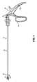
図1は、本開示によるマニュアル式のクリップアプライヤ10を示している。クリップアプライヤ10は、遠位エンドエフェクタを有し、この遠位エンドエフェクタは、細長いシャフト30の遠位端に設けられたジャー機構20と、細長いシャフト30の近位端に設けられたハンドル機構40を備えている。ジャー機構20は、第1ジャー部材22と、第2ジャー部材24と、これらの第1ジャー部材22と第2ジャー部材24との間に設けられた安定化部材26を備えている。ジャー機構20は、細長いシャフト30を通って延びている作動部材32を介してハンドル帰庫40により作動されるようになっている。ハンドル機構40は、第1ハンドル部材42と、第2ハンドル部材44を備えている。例えば、細長いシャフト30の近位端は、第1ハンドル部材42に取り付けられ、作動部材32の近位端は、第2ハンド部材44に取り付けられ、ハンドル部材42、44の相対動作又は揺動動作により、作動部材32が相対動作し、ジャー機構20を作動させるようになっている。
ジャー機構20は、清掃のために、ハンドル機構40及び細長いシャフト30に取り外し可能に取り付けられている。例えば、遠位エンドエフェクタのピンは、細長いシャフト30の遠位端のスロットに受け入れられるようになっている。第1ジャー部材22、第2ジャー部材24及び安定化部材26の作動を、以下の実施形態において説明する。FIG. 1 shows a
図2乃至図5は、図1のマニュアル式のクリップアプライヤ10の遠位エンドエフェクタの第1実施形態100を示している。クリップアプライヤ100は、手術用クリップ50(図4と図5参照)を使用するように構成されている。クリップアプライヤ100は、第1ジャー部材102、第2ジャー部材104、安定化部材106、シャフト108、及び、ハンドル機構(図1参照)を備えている。ハンドル機構を作動させて、作動部材(例えば、作動ロッド)110をシャフト108内で引き戻したり及び/又は押したりすることにより、第1及び第2ジャー部材102、104を開状態(図4参照)と閉状態(図5参照)の間を揺動させるようになっている。第1及び第2ジャー部材102、104は、ヒンジ部56を中心にして第1及び第2脚部材52、54を揺動させて、手術用クリップ50を押し付けるようになっている。 2-5 illustrate a
第1及び第2ジャー部材102、104は、ヒンジ機構112で揺動可能に結合され、このヒンジ機構112は、シャフト108の遠位部分109に設けられた揺動ピン118を備えている。第1及び第2ジャー部材102、104は、第1及び第2ジャー部材102、104の間で手術用クリップ50を受け入れるようになっており、さらに、第1及び第2ジャー部材102、104は、第1及び第2脚部材52、54の遠位部分での接触点において手術用クリップ50を安定化させるようになっている。例えば、図2乃至図5に示すように、第1及び第2ジャー部材102、104は、1又はそれ以上の溝114を備えた遠位部分を備え、これらの溝が、第1及び第2脚部材52、54の遠位部分に設けられた1又はそれ以上のボス58を受け入れるようになっている。第1及び第2ジャー部材102、104の各々は、更に、長手方向のチャネル116を備え、この長手方向のチャネル116が、手術用クリップ50及び/又は安定化部材106を受け入れるように構成されている。 The first and
安定化部材106は、手術用クリップ50をさらに安定化させるために、第1及び第2ジャー部材102、104の間に受け入れられるようになっている。安定化部材106は、細長い本体を有し、この本体は、手術用クリップ50の近位部分(例えば、ヒンジ部56)を受け入れる及び/又は近位部分と係合する遠位部分120を備えている。遠位部分120は、垂直壁又は突出部122を備え、これらは、安定化部材106の対向する側で細長い本体の遠位部分120から延びている。例えば、垂直壁122は、安定化部材106の細長い本体の対向する側面と一体であり、側面に溶接され、及び/又は、側面に固定されており、これにより、垂直壁122により規定される幅は、安定化部材106の残りの長さ部分の幅よりも広くなっている。垂直壁122は、それらの間に手術用クリップ50の近位部分(例えば、ヒンジ部56)を受け入れるように構成されたチャネル124を形成し、手術用クリップ50の横方向の動きを少なくしている。垂直壁122は、実質的に平行で、且つ、遠位部分120の全高を越えない。遠位部分120は、更に、垂直壁122の間で横方向に延びる横方向突出部(図示せず)を備え、これが手術用クリップ50の近位部分に係合するようになっている。遠位部分120は、第1及び第2ジャー部材102、104の間に位置しているとき、手術用クリップ50を、横方向及び/又は垂直方向において、受け取り、把持し、及び/又は、安定化する。安定化部材106の遠位部分120の実施形態が、米国特許出願公開2018/0271534号明細書に記載されており、この明細書の開示は、本明細書に含まれる。 A stabilizing
安定化部材106は、第1及び第2ジャー部材102、104の間で対称に配置されている。安定化部材106の配置により、使用者が、2つの相対する方向の何れかから、クリップアプライヤ100のクリップカートリッジ(図示せず)から手術用クリップ50を取り出すことができるようになっている。例えば、第1ジャー部材102は、手術用クリップ50の第1脚部材52又は第2脚部材54の一方に係合し、第2ジャー部材104は、手術用クリップ50の第1脚部材52又は第2脚部材54の他方に係合する。クリップアプライヤ100と手術用クリップ50との間の3点の係合により、手術用クリップ50の安全性が増す。2点の接触は、第1及び第2脚部材52,54の遠位面において、手術用クリップ50で生じ、3つ目の点の接触は、手術用クリップ50(例えば、ヒンジ部56)の近位部に生じる。手術用クリップ50は、外部からの力が作用しても、第1及び第2ジャー部材102、104の間で積極的に係合された状態を維持することができる。 A stabilizing
図4及び図5に示すように、第1及び第2ジャー部材102、104は、第1及び第2脚部材52、54に反対方向の力を作用させることにより手術用クリップ50を押し付けるように構成されている。クリップアプライヤ100においては、安定化部材106が遠位位置にあるとき、第1及び第2ジャー部材102、104は脚部材52,54(例えば、溝114に係合した手術用クリップのボス)の遠位部分に係合し、且つ、ヒンジ部56は安定化部材106の垂直壁122の間に受け入れられるように、手術用クリップ50はクリップカートリッジ(図示せず)から最初負荷がかけられている。
ハンドル機構を作動させると、シャフト108の遠位部分109に受け入れられたリンク機構140を介して第1及び第2ジャー部材102、104に結合された作動部材110が引き戻される。例えば、第1リンク142は、作動部材110に揺動可能に結合された第1端部と、第1ジャー部材102の近位端に揺動可能に結合された第2端部を備えている。第2リンク144は、作動部材110に揺動可能に結合された第1端部と、第2ジャー部材104の近位端に揺動可能に結合された第2端部を備えている。リンク機構140には、ヒンジ機構112の近位部分が取り付けられ、作動部材110を引き戻すことにより、第1及び第2ジャー部材102、104が閉状態に向けて揺動する。遠位部分109は開となり且つシャフト108の近位部分に対して広くなり、これにより、遠位部分109は、揺動ピン118の回りを揺動したジャー部材102、104の近位端を受け入れることができる。As shown in FIGS. 4 and 5, the first and second jaw members 102,104 compress the
Actuation of the handle mechanism retracts an actuating
第1及び第2ジャー部材102、104が揺動するので、安定化部材106は、第1及び第2ジャー部材102、104(図4参照)の間の少なくとも一部の第1の遠位位置(第1位置)と第1及び第2ジャー部材102、104(図5参照)の間の少なくとも一部の第2の近位位置(第2位置)との間を長手方向に動くように構成されている。安定化部材106は、第1位置と第2位置との間の長手方向の動きが強要される。安定化部材106の細長い本体は、第1及び第2ジャー部材102、104の揺動が妨げられないようにするために、第1位置及び/又は第2位置において、第1ジャー部材102及び/又は第2ジャー部材104の長手方向のチャネル116に受け入れられるようになっている。手術用クリップ50が圧縮された後には、第1及び第2ジャー部材102、104は、開状態に向けて揺動し、安定化部材106は第1の遠位位置に戻りカートリッジからの第2の手術用クリップ50と係合する。
As the first and
図4と図5に示すように、安定化部材106は、第1及び第2ジャー部材102、104の揺動により直接的に作動されるようになっている。例えば、安定化部材106は、1又はそれ以上のジャー部材102、104のピン128をスライド可能に受け入れる1又はそれ以上のスロット126を備えている。このようにして、ピン128は、ジャー部材102、104が開状態のとき、スロット126内の近位位置にあり、安定化部材106は、遠位位置にあり、手術用クリップ50(図4参照)と係合するようになっている。
ジャー部材102、104が閉位置に向けて揺動するので、ピン128は、スロット126を介して遠位位置までスライドし、このとき、ジャー部材102、104は閉状態であり、且つ、安定化部材106は近位位置にあり手術用クリップ50(図5参照)との係合が解かれる。
更に、図4と図5に示すように、安定化部材106は、第1及び第2スロット126を備え、これらのスロット126が第1及び第2ジャー部材102、104の各々からピン128を受け入れ、これにより、シャフト108に対して、第1及び第2ジャー部材102、104の両方が揺動できるようになっている。しかしながら、他の実施形態(図示せず)においては、安定化部材106は、単一のスロット106を備え、この場合には、第1及び第2ジャー部材102、104の一方のみが揺動するのが望ましい。
スロット126は、クリップアプライヤ100の長手方向軸に対して直線的に傾いており、この場合には、ピン128は、スロット126を通って長手方向及び垂直方向に同時に動くようになっている。こうして、安定化部材106は、第1及び第2ジャー部材102、104が互いに向かって揺動しながら、長手方向に押し戻される。スロット126は、好ましくは、直線的/真っ直ぐであるが、カーブさせて、ジャー部材102、104の揺動と、安定化部材106の長手方向の動きを同時に行うようにしてもよい。As shown in FIGS. 4 and 5, the stabilizing
As the
4 and 5, stabilizing
安定化部材106は、延長部130によって、垂直に及び/又は横方向に安定化されている。延長部130は、安定化部材106と一体化構造であり、近位方向に延び、さらに、シャフト108の遠位部分109の長手方向のスロット132と係合している。延長部130は、作動中に長手方向のスロット132を通って長手方向にスライドするが、このとき、延長部130の横方向及び/又は垂直方向の遊び/動きを防ぐようになっている。このようにして、安定化部材106は、実質的な回転や遊びがなく、第1及び第2ジャー部材102、104のピン128に対して長手方向に動くようになっている。 Stabilizing
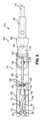
図6及び図7は、図1に示すマニュアル式のクリップアプライヤ10の遠位エンドエフェクタの第2実施形態200を示す。クリップアプライヤ200は、手術用クリップ50を使用できるように構成されている。クリップアプライヤ200は、第1ジャー部材202と、第2ジャー部材204と、安定化部材206と、シャフト208と、ハンドル機構(図1に示されている)を備えている。
ハンドル機構を作動させて、作動部材(例えば、作動ロッド)210をシャフト208内で引き戻したり及び/又は押したりすることにより、第1及び第2ジャー部材202、204を開状態(図6参照)と閉状態(図7参照)の間を揺動させるようになっている。第1及び第2ジャー部材202、204は、ヒンジ部56を中心にして第1及び第2脚部材52、54を揺動させて、手術用クリップ50を押し付けるようになっている。6 and 7 show a
By actuating the handle mechanism to pull back and/or push the actuating member (eg, actuating rod) 210 within the
第1及び第2ジャー部材202、204は、ヒンジ機構212で揺動可能に結合され、このヒンジ機構212は、シャフト208の遠位部分209に設けられた揺動ピン218を備えている。第1及び第2ジャー部材202、204は、第1及び第2ジャー部材202、204の間で手術用クリップ50を受け入れるようになっており、さらに、第1及び第2ジャー部材202、204は、第1及び第2脚部材52、54の遠位部分での接触点において手術用クリップ50を安定化させるようになっている。例えば、図2乃至図5に示すように、第1及び第2ジャー部材202、204は、1又はそれ以上の溝214を備えた遠位部分を備え、これらの溝が、第1及び第2脚部材52、54の遠位部分に設けられた1又はそれ以上のボス58を受け入れるようになっている。第1及び第2ジャー部材202、204の各々は、更に、長手方向のチャネル216を備え、この長手方向のチャネル216が、手術用クリップ50及び/又は安定化部材206を受け入れるように構成されている。 The first and
安定化部材206は、手術用クリップ50をさらに安定化させるために、第1及び第2ジャー部材202、204の間に受け入れられるようになっている。安定化部材206は、細長い本体を有し、この本体は、手術用クリップ50の近位部分(例えば、ヒンジ部56)を受け入れる及び/又は近位部分と係合する遠位部分220を備えている。遠位部分220は、垂直壁又は突出部222を備え、これらは、安定化部材206の対向する側で細長い本体の遠位部分220から延びている。垂直壁222は、それらの間に手術用クリップ50の近位部分(例えば、ヒンジ部56)を受け入れるように構成されたチャネル224を形成し、手術用クリップ50の横方向の動きを少なくしている。例えば、垂直壁222は、安定化部材206の細長い本体の対向する側面と一体であり、側面に溶接され、及び/又は、側面に固定されており、これにより、垂直壁222により規定される幅は、安定化部材206の残りの長さ部分の幅よりも広くなっている。垂直壁222は、実質的に平行で、且つ、遠位部分220の全高を越えない。遠位部分220は、更に、垂直壁222の間で横方向に延びる横方向突出部(図示せず)を備え、これが手術用クリップ50の近位部分に係合するようになっている。遠位部分220は、第1及び第2ジャー部材202、204の間に位置しているとき、手術用クリップ50を、横方向及び/又は垂直方向において、受け取り、把持し、及び/又は、安定化する。 A stabilizing
安定化部材206は、第1及び第2ジャー部材202、204の間で対称に配置されている。安定化部材206の配置により、使用者が、2つの相対する方向の何れかから、クリップアプライヤ200のクリップカートリッジ(図示せず)から手術用クリップ50を取り出すことができるようになっている。例えば、第1ジャー部材202は、手術用クリップ50の第1脚部材52又は第2脚部材54の一方に係合し、第2ジャー部材204は、手術用クリップ50の第1脚部材52又は第2脚部材54の他方に係合する。クリップアプライヤ200と手術用クリップ50との間の3点の係合により、手術用クリップ50の安全性が増す。2点の接触は、第1及び第2脚部材52,54の遠位面において、手術用クリップ50で生じ、3つ目の点の接触は、手術用クリップ50(例えば、ヒンジ部56)の近位部に生じる。手術用クリップ50は、外部からの力が作用しても、第1及び第2ジャー部材202、204の間で積極的に係合された状態を維持することができる。 A stabilizing
図6及び図7に示すように、第1及び第2ジャー部材202、204は、第1及び第2脚部材52、54に反対方向の力を作用させることにより手術用クリップ50を押し付けるように構成されている。クリップアプライヤ200においては、第1及び第2ジャー部材202、204は脚部材52,54(例えば、溝214)の遠位部分に係合し、且つ、ヒンジ部56は安定化部材206の垂直壁222の間に受け入れられるように、手術用クリップ50はクリップカートリッジ(図示せず)から最初負荷がかけられている。
ハンドル機構を作動させると、リンク機構240を介して第1及び第2ジャー部材202、204に結合された作動部材210が引き戻される。例えば、第1リンク242は、作動部材210に揺動可能に結合された第1端部と、第1ジャー部材202の近位端に揺動可能に結合された第2端部を備えている。第2リンク244は、作動部材210に揺動可能に結合された第1端部と、第2ジャー部材204の近位端に揺動可能に結合された第2端部を備えている。リンク機構240には、ヒンジ機構212の近位部分が取り付けられ、作動部材210を引き戻すことにより、第1及び第2ジャー部材202、204が閉状態に向けて揺動する。As shown in FIGS. 6 and 7, the first and second jaw members 202,204 compress the
Actuation of the handle mechanism retracts the actuating
第1及び第2ジャー部材202、204が揺動するので、安定化部材206は、第1及び第2ジャー部材202、204(図6参照)の間の少なくとも一部の第1の遠位位置(第1位置)と第1及び第2ジャー部材202、204(図6参照)の間の少なくとも一部の第2の近位位置(第2位置)との間を長手方向に動くように構成されている。安定化部材206は、第1位置と第2位置との間の長手方向の動きが強要される。安定化部材206は、第1及び第2ジャー部材202、204の揺動が妨げられないようにするために、第1位置及び/又は第2位置において、第1ジャー部材202及び/又は第2ジャー部材204の長手方向のチャネル216に受け入れられるようになっている。手術用クリップ50が圧縮された後には、第1及び第2ジャー部材202、204は、開状態に向けて揺動し、安定化部材206は第1の遠位位置に戻りカートリッジからの第2の手術用クリップ50と係合する。クリップアプライヤ200は、他の記載されない限り、クリップアプライヤ100に類似した特徴及び機構を有する。
As the first and
図6と図7に示すように、安定化部材206は、作動部材210の長手方向の動きにより、直接的に作動されるようになっている。安定化部材206は、作動部材210に直接的に(例えば、一体的に)取り付けられている。このため、図6と図7に示すように、作動部材210は、ハンドル機構から延び、リンク機構240を通り、揺動ピン218を通り、さらに、安定化部材206に直接的に(例えば、一体的に)取り付けられている。作動部材210を押し戻したり押し進めることにより、安定化部材206を直接的に押し戻したり押し進めることができるようになっている。 As shown in FIGS. 6 and 7, stabilizing
図4乃至図7に示すように、手術用クリップ50の第1脚部材52は、凹形状の内側面と、遠位部分にフック部材を備え、第2脚部材54は、凸形状の内側面と、遠位部分にチップ(先端)部材を備えている。手術用クリップ50を閉じると、第1脚部材52のフックが、第2脚部材54のチップ部材の回りで変形し、ラッチ構造となって、手術用クリップ50を固定するようになっている。
湾曲面により、第1及び/又は第2脚部材52、54は、閉じる及び/又はラッチ工程において、真っ直ぐ及び/又は細長くなる。
安定化部材106、206は、それが押し戻されることにより、閉じつつある及び/又はラッチされつつある手術用クリップ50との干渉を避けることができる。さらに、安定化部材106、206は、それが押し戻されることにより、手術用クリップ50を閉じた及び/又はラッチされた後に、手術用クリップ50を取り外すことが容易となる。As shown in FIGS. 4-7,
The curved surface causes the first and/or
The stabilizing
手術用クリップ50は、適切なサイズで製作され、更に、血管、リンパ節、神経、卵管、心臓組織等の多種類の組織に使用可能である。手術用クリップ50は、金属やポリマー等の生体適合性の材料から製作される。ある実施形態においては、手術クリップ50は、外科移植に使用される共重合体のような適切な強力な生体適合性工学的プラスチックから作られた一体型重合体から構成されている。材料として、ホモポリマー又は共重合体ポリアセタール、ポリエチレンテレフタレート(PET)、ポリブチレンテレフタレート(PBT)、ポリオクシメチレン、又は、インジェクションモールドや押出成形による製作が可能な他の熱可塑性材料が用いられる。
手術用クリップ50の実施形態は、米国特許第4834096号明細書に記載され、この明細書における開示内容は本明細書に参考として含まれる。手術用クリップ50を含むカートリッジの実施形態は、米国特許第6880699号明細書に記載され、この明細書における開示内容は本明細書に参考として含まれる。
An embodiment of
本発明の多くの特徴や利点は、上述した説明から明らかであり、そのため、特許請求の範囲はこのような本発明の特徴や利点をカバーする。本発明は、上述した実施形態に限定されず、全ての適切な変形例や均等物を含む。 Many features and advantages of the present invention are apparent from the foregoing description, and the claims therefore cover such features and advantages of the present invention. The invention is not limited to the embodiments described above, but includes all suitable modifications and equivalents.
Claims (13)
Translated fromJapanese前記手術用クリップと係合するように構成された第1ジャー部材及び第2ジャー部材と、
前記第1ジャー部材と第2ジャー部材の少なくとも一方を開状態と閉状態との間で揺動させる作動部材と、
前記手術用クリップと係合する安定化部材であって、この安定化部材は、前記第1ジャー部材と第2ジャー部材の間の少なくとも一部である遠位位置から前記第1ジャー部材と第2ジャー部材の間の少なくとも一部である近位位置まで前記クリップアプライヤに関して長手方向に沿って移動するように構成された前記安定化部材と、
前記安定化部材を前記第1ジャー部材及び/又は前記第2ジャー部材に接続する少なくとも1つのピンと、を有し、
前記少なくとも1つのピンが、前記安定化部材の遠位位置と近位位置の間の移動を作動する、クリップアプライヤ。A clip applier for using surgical clips, the clip applier comprising:
first and second plunger members configured to engage the surgical clip;
an operating member that swings at least one of the first jar member and the second jar member between an open state and a closed state;
A stabilizing member for engaging the surgical clip, the stabilizing member extending from a distal location that is at least partially between the first and second plunger members and the first and second plunger members. said stabilizing member configured to move longitudinally relative to said clip applier to a proximal position that is at least partially between two jar members;
at least one pin connecting said stabilizing member to said first jar member and/or said second jar member ;
The clip applier, wherein the at least one pinactuates movement of the stabilizing member between distal and proximal positions.
Priority Applications (1)
| Application Number | Priority Date | Filing Date | Title |
|---|---|---|---|
| JP2023041271AJP7661384B2 (en) | 2018-09-26 | 2023-03-15 | Clip applier with stabilizing member |
Applications Claiming Priority (3)
| Application Number | Priority Date | Filing Date | Title |
|---|---|---|---|
| US201862737043P | 2018-09-26 | 2018-09-26 | |
| US62/737,043 | 2018-09-26 | ||
| PCT/US2019/053145WO2020069123A1 (en) | 2018-09-26 | 2019-09-26 | Clip applier with stabilizing member |
Related Child Applications (1)
| Application Number | Title | Priority Date | Filing Date |
|---|---|---|---|
| JP2023041271ADivisionJP7661384B2 (en) | 2018-09-26 | 2023-03-15 | Clip applier with stabilizing member |
Publications (3)
| Publication Number | Publication Date |
|---|---|
| JP2022502181A JP2022502181A (en) | 2022-01-11 |
| JPWO2020069123A5 JPWO2020069123A5 (en) | 2022-11-22 |
| JP7247330B2true JP7247330B2 (en) | 2023-03-28 |
Family
ID=69953375
Family Applications (2)
| Application Number | Title | Priority Date | Filing Date |
|---|---|---|---|
| JP2021517267AActiveJP7247330B2 (en) | 2018-09-26 | 2019-09-26 | Clip applier with stabilizing member |
| JP2023041271AActiveJP7661384B2 (en) | 2018-09-26 | 2023-03-15 | Clip applier with stabilizing member |
Family Applications After (1)
| Application Number | Title | Priority Date | Filing Date |
|---|---|---|---|
| JP2023041271AActiveJP7661384B2 (en) | 2018-09-26 | 2023-03-15 | Clip applier with stabilizing member |
Country Status (5)
| Country | Link |
|---|---|
| US (2) | US12279774B2 (en) |
| EP (1) | EP3856047A4 (en) |
| JP (2) | JP7247330B2 (en) |
| CN (2) | CN112867451B (en) |
| WO (1) | WO2020069123A1 (en) |
Families Citing this family (2)
| Publication number | Priority date | Publication date | Assignee | Title |
|---|---|---|---|---|
| KR102647625B1 (en)* | 2018-07-18 | 2024-03-14 | 텔리플렉스 메디컬 인코포레이티드 | Clip Appliers and Cartridges |
| JP7728963B2 (en)* | 2021-09-01 | 2025-08-25 | ボストン サイエンティフィック サイムド,インコーポレイテッド | Devices, systems, and methods for clamping the leaflets of a heart valve |
Citations (3)
| Publication number | Priority date | Publication date | Assignee | Title |
|---|---|---|---|---|
| JP2004522468A (en) | 2000-10-23 | 2004-07-29 | ビタリテック・アンテルナショナル・ソシエテ・アノニム | Surgical automatic clip applier |
| US20120083803A1 (en) | 2010-10-02 | 2012-04-05 | Patel Manoj B | Asymmetrical surgical clip with penetrating lock, non-slip clamping surface, severable hinge, hinge boss and pivoting applicator tip |
| JP2015043977A (en) | 2013-08-27 | 2015-03-12 | コヴィディエン リミテッド パートナーシップ | Surgical clip applier |
Family Cites Families (318)
| Publication number | Priority date | Publication date | Assignee | Title |
|---|---|---|---|---|
| US929868A (en) | 1908-09-17 | 1909-08-03 | Carl L Mueller | Detachable-jaw tool. |
| US1482290A (en) | 1921-02-02 | 1924-01-29 | Elzi Peter Frank | Bending tool |
| US1728322A (en) | 1928-02-22 | 1929-09-17 | Badrian Max | Device for elastically clamping off the male urethra |
| US2384697A (en) | 1944-10-18 | 1945-09-11 | Riccardi Peter | Umbilical clip |
| US2635238A (en) | 1949-07-11 | 1953-04-21 | Garland Mather | Apparatus for clamping umbilical cords and the like |
| US2626608A (en) | 1949-12-08 | 1953-01-27 | Garland Mather | Clamp for umbilical cords and the like |
| US2598901A (en) | 1950-03-10 | 1952-06-03 | Garland Mather | Clamp for constricting flexible tubular elements and the like |
| US2594102A (en) | 1950-05-03 | 1952-04-22 | Vollmer Leonhard | Automatic inserter for suturing clips |
| US2744251A (en) | 1953-06-04 | 1956-05-08 | Vollmer Leonhard | Automatic inserter for suturing clips |
| US2881762A (en) | 1955-02-09 | 1959-04-14 | Robert J Lowrie | Surgical staple and stapler |
| US2890519A (en) | 1955-08-01 | 1959-06-16 | Storz Instr Co | Surgical spring clip forceps |
| US2813269A (en) | 1956-01-25 | 1957-11-19 | Jacobs John Bay | Implement for applying an umbilical cord seal and identifying newly born babies |
| US2814222A (en) | 1956-07-16 | 1957-11-26 | Emmitt G Sanders | Ferrule crimping pliers with replaceable jaws |
| US3032039A (en) | 1959-05-26 | 1962-05-01 | Jack O Beaty | Arterial and veinous clamp and clamp applicator |
| US3150379A (en)* | 1962-03-01 | 1964-09-29 | Ernest C Wood | Single clip disposable applicator |
| US3172133A (en) | 1962-05-14 | 1965-03-09 | Olympio C Rizzo | Long nose pliers with cutting attachment |
| US3463156A (en) | 1965-05-27 | 1969-08-26 | Edward B Mcdermott | Hemostatic clip and applicator |
| US3446212A (en) | 1965-07-19 | 1969-05-27 | New Research & Dev Lab Inc | Hemostatic clip and applicator therefor |
| US3503398A (en) | 1965-09-10 | 1970-03-31 | American Hospital Supply Corp | Atraumatic clamp for vascular surgery |
| US3351191A (en) | 1965-09-30 | 1967-11-07 | Codman & Shurtleff | Surgical staple cartridge |
| US3503396A (en) | 1967-09-21 | 1970-03-31 | American Hospital Supply Corp | Atraumatic surgical clamp |
| US3503397A (en) | 1967-09-21 | 1970-03-31 | American Hospital Supply Corp | Atraumatic surgical clamp |
| US3713533A (en) | 1971-04-28 | 1973-01-30 | Codman & Shurtleff | Hemostatic clip holder |
| US3766925A (en) | 1971-05-25 | 1973-10-23 | Eljay Hospital Prod Corp | Surgical clamp with cam-action lever |
| US3827438A (en) | 1972-07-10 | 1974-08-06 | G Kees | Aneurysm clip |
| US3867944A (en) | 1972-10-27 | 1975-02-25 | Wood Ernest C | Hemostatic clip and applicator therefor |
| US3954108A (en) | 1972-11-03 | 1976-05-04 | Davis Hugh J | Occlusion clip and instrument for applying same |
| US3874042A (en) | 1973-01-22 | 1975-04-01 | Biospectrum Inc | Clamp for thin walled tubing |
| US3825012A (en) | 1973-04-13 | 1974-07-23 | H Nicoll | Reusable umbilical cord clamp for veterinary use |
| DE2730691C2 (en) | 1976-07-16 | 1982-12-16 | Maruho Co. Ltd., Osaka | Surgical clip, connecting element for several surgical clips and forceps for opening and closing the same |
| US4120302A (en) | 1976-10-08 | 1978-10-17 | American Hospital Supply Corporation | Disposable pads for surgical instruments |
| US4076120A (en) | 1976-12-10 | 1978-02-28 | American Hospital Supply Corporation | Cartridge for holding hemostatic clips |
| CA1082552A (en) | 1977-08-05 | 1980-07-29 | Charles H. Klieman | Hemostatic clip applicator |
| US4316468A (en) | 1977-08-05 | 1982-02-23 | Charles H. Klieman | Surgical stapler |
| US4337774A (en) | 1978-06-14 | 1982-07-06 | Metatech Corporation | Micro surgical clip |
| US4428374A (en) | 1978-12-20 | 1984-01-31 | Auburn Robert M | Umbilical cord clamping assembly |
| US4390019A (en) | 1979-02-28 | 1983-06-28 | Leveen Harry H | Blood vessel clamp |
| US4527562A (en) | 1979-06-18 | 1985-07-09 | Ethicon, Inc. | Non-metallic, bio-compatible hemostatic clips |
| US4418694A (en) | 1979-06-18 | 1983-12-06 | Ethicon, Inc. | Non-metallic, bio-compatible hemostatic clips |
| CA1157335A (en) | 1979-06-18 | 1983-11-22 | Namassivaya Doddi | Plastic ligating clips |
| US4638804A (en) | 1980-02-25 | 1987-01-27 | Ethicon, Inc. | Double-latched non-metallic, bio-compatible hemostatic clip |
| MX151148A (en) | 1980-02-25 | 1984-10-04 | Johnson & Johnson | IMPROVEMENTS IN HEMOSTATIC FORCEPS |
| US4345600A (en) | 1980-08-04 | 1982-08-24 | Senco Products, Inc. | Purse-stringer |
| US4344531A (en) | 1980-09-08 | 1982-08-17 | Edward Weck & Company, Inc. | Hemostatic clip cartridge |
| US4414721A (en) | 1980-11-07 | 1983-11-15 | Hufnagel Charles A | Occlusive clip and applicator for constricting flexible tubular members |
| US4346869A (en) | 1981-03-12 | 1982-08-31 | Macneill Robert L | Tube clamp |
| US4394864A (en)* | 1981-04-15 | 1983-07-26 | Jeffrey Sandhaus | Apparatus and method for effecting occlusion of the vas deferens |
| US4550729A (en) | 1981-08-27 | 1985-11-05 | Ethicon, Inc. | Non-metallic, bio-compatible hemostatic clips with interlocking latch means |
| US4570633A (en) | 1981-09-28 | 1986-02-18 | Ethicon, Inc. | Surgical clip applier instrument adapter jaws |
| US4487204A (en) | 1981-10-14 | 1984-12-11 | Nomel | Device for applying haemostatic clips |
| US4471780A (en) | 1982-02-05 | 1984-09-18 | Ethicon, Inc. | Multiple ligating clip applier instrument |
| US4476865A (en) | 1982-02-12 | 1984-10-16 | Ethicon, Inc. | Non-metallic, bio-compatible hemostatic clips |
| US4450840A (en) | 1982-02-26 | 1984-05-29 | Ethicon, Inc. | Ligating clip with flanged base having a recessed engaging face |
| US4487205A (en) | 1982-04-26 | 1984-12-11 | Ethicon, Inc. | Non-metallic, bio-compatible hemostatic clips |
| US4458682A (en) | 1982-08-02 | 1984-07-10 | Ethicon, Inc. | Non-metallic, bio-compatible hemostatic clips (ring lock clips) |
| US4671281A (en) | 1982-09-13 | 1987-06-09 | Ethicon, Inc. | Non-metallic, bio-compatible hemostatic clips (one piece wedge clip) |
| US4509517A (en) | 1982-09-30 | 1985-04-09 | Zibelin Henry S | Kidney stone instrument |
| US4492232A (en) | 1982-09-30 | 1985-01-08 | United States Surgical Corporation | Surgical clip applying apparatus having fixed jaws |
| US4519392A (en) | 1982-10-12 | 1985-05-28 | Lingua Robert W | Hemostasing muscle clips for needleless surgery |
| US4534351A (en) | 1982-10-20 | 1985-08-13 | Senmed, Inc. | Ligator |
| US4444187A (en) | 1982-12-09 | 1984-04-24 | Metatech Corporation | Miniature surgical clip for clamping small blood vessels in brain surgery and the like |
| US4579118A (en) | 1983-06-01 | 1986-04-01 | Ethicon, Inc. | Hemostatic clip with penetration means |
| US4919152A (en) | 1987-03-02 | 1990-04-24 | Ralph Ger | Method of closing the opening of a hernial sac |
| US5127915A (en) | 1984-10-29 | 1992-07-07 | Mattson Philip D | Surgical instrument for severing and clamping an umbilical cord |
| US4589626A (en) | 1985-03-13 | 1986-05-20 | Bioresearch Inc. | Hose clamp |
| US4588160A (en) | 1985-03-27 | 1986-05-13 | Sherwood Medical Company | Tube clamping device |
| US4616651A (en) | 1985-04-15 | 1986-10-14 | Ethicon, Inc. | Surgical clip applier instrument adapter jaws |
| JPH0657218B2 (en) | 1985-05-10 | 1994-08-03 | エチコン・インコ−ポレ−テツド | Ligation clip and clip application device |
| US4712549A (en) | 1985-07-01 | 1987-12-15 | Edward Weck & Co. | Automatic hemostatic clip applier |
| US5047038A (en) | 1985-07-01 | 1991-09-10 | Edward Weck Incorporated | Automatic hemostatic clip applier |
| US4807622A (en) | 1985-09-20 | 1989-02-28 | Kato Hatsujo Kaisha, Ltd. | Tube cutting and separating implement for conduit of blood or the like |
| US4924864A (en) | 1985-11-15 | 1990-05-15 | Danzig Fred G | Apparatus and article for ligating blood vessels, nerves and other anatomical structures |
| US4686983A (en) | 1986-04-08 | 1987-08-18 | Gerald Leisman | Apparatus and method for ligating a body vessel |
| US4716886A (en) | 1986-05-01 | 1988-01-05 | Norman Schulman | Umbilical cord clamp and cutters |
| US4726372A (en) | 1986-09-19 | 1988-02-23 | Metatech Corporation | Hemostatic clip |
| DE3704760C1 (en) | 1987-02-16 | 1988-03-03 | Aesculap Werke Ag | Application device for C-shaped scalp clips |
| US4834090A (en) | 1987-03-02 | 1989-05-30 | Moore J Paul | Suture boot |
| US4822348A (en) | 1987-05-13 | 1989-04-18 | Donn Casey | Surgical clips |
| US4834096A (en) | 1987-10-26 | 1989-05-30 | Edward Weck Incorporated | Plastic ligating clips |
| GB2212201B (en) | 1987-11-10 | 1992-06-03 | Donn Casey | Surgical clip |
| US4870965A (en) | 1988-03-04 | 1989-10-03 | Jahanger Mohammed S | Umbilical cord cutting and clamping device |
| US5053045A (en) | 1988-09-16 | 1991-10-01 | Schmidt Ferenc J | Surgical clip |
| US5172700A (en) | 1989-01-31 | 1992-12-22 | C. R. Bard, Inc. | Disposable biopsy forceps |
| US4942886A (en) | 1989-02-22 | 1990-07-24 | Timmons John W | External incontinency device |
| US5062846A (en) | 1989-03-28 | 1991-11-05 | Edward Weck Incorporated | Penetrating plastic ligating clip |
| US4976722A (en) | 1989-05-22 | 1990-12-11 | Ethicon, Inc. | Surgical hemostatic clips |
| US4938764A (en) | 1989-06-02 | 1990-07-03 | John Glaberson | Tick remover |
| US4938765A (en) | 1989-06-22 | 1990-07-03 | Life Centers, Inc. | Surgical silicon loops |
| US5104395A (en) | 1989-07-03 | 1992-04-14 | Edward Weck Incorporated | Automatic hemostatic clip applicator |
| US4950275A (en) | 1989-07-19 | 1990-08-21 | Cyanamid Italia S.P.A. | Bowel-anastomosis-ring holder pincers |
| US4972949A (en) | 1989-09-26 | 1990-11-27 | Horizon Surgical, Inc. | Hemostatic clip holder for small clips |
| US4936447A (en) | 1989-09-26 | 1990-06-26 | Horizon Surgical Inc. | Hemostatic clip holder |
| US5100416A (en) | 1989-10-17 | 1992-03-31 | Edward Weck Incorporated | Ligating clip applying instrument |
| US5009657A (en) | 1989-12-14 | 1991-04-23 | Mohammed S. Jahanger | Umbilical cord cutting and clamping device |
| US4961499A (en) | 1990-01-04 | 1990-10-09 | Pilling Co. | Hemostatic clip cartridge |
| NZ233737A (en) | 1990-05-18 | 1992-12-23 | Allflex New Zealand | Applicator for one-piece ear tag formed into an annulus |
| US5078731A (en) | 1990-06-05 | 1992-01-07 | Hayhurst John O | Suture clip |
| US5207692A (en) | 1990-07-30 | 1993-05-04 | Codman & Shurtleff, Inc. | Surgical clip applier with reciprocating clip sleeve and dual ratchet mechanism |
| US5026382A (en) | 1990-08-27 | 1991-06-25 | Horizon Surgical, Inc. | Hemostatic clip |
| US5201416A (en) | 1990-10-22 | 1993-04-13 | Edward Weck Incorporated | Hemostatic clip cartridge |
| US5046611A (en) | 1990-10-22 | 1991-09-10 | Edward Weck Incorporated | Hemostatic clip cartridge |
| US5366458A (en) | 1990-12-13 | 1994-11-22 | United States Surgical Corporation | Latchless surgical clip |
| US5171252A (en) | 1991-02-05 | 1992-12-15 | Friedland Thomas W | Surgical fastening clip formed of a shape memory alloy, a method of making such a clip and a method of using such a clip |
| US5112343A (en) | 1991-04-05 | 1992-05-12 | Edward Weck Incorporated | Endoscopic clip appliers |
| US5160339A (en) | 1991-06-18 | 1992-11-03 | Ethicon, Inc. | Endoscopic suture clip |
| US5163945A (en) | 1991-10-18 | 1992-11-17 | Ethicon, Inc. | Surgical clip applier |
| US5259405A (en) | 1992-01-29 | 1993-11-09 | Hua Chou Kuo | Structure of a barette |
| US5171251A (en) | 1992-03-02 | 1992-12-15 | Ethicon, Inc. | Surgical clip having hole therein and method of anchoring suture |
| US5246450A (en) | 1992-03-10 | 1993-09-21 | Edward Weck Incorporated | High capacity medical clip feeding and dispensing mechanism |
| US5318589A (en) | 1992-04-15 | 1994-06-07 | Microsurge, Inc. | Surgical instrument for endoscopic surgery |
| US5279416A (en) | 1992-06-05 | 1994-01-18 | Edward Weck Incorporated | Ligating device cartridge with separable retainer |
| DK0717962T3 (en)* | 1992-06-30 | 1999-10-25 | Sherwood Serv Ag | Modular tie-down clamp applicator |
| US5234449A (en) | 1992-07-16 | 1993-08-10 | Ethicon, Inc. | Suture clip with reduced hinge mass |
| US5330442A (en) | 1992-10-09 | 1994-07-19 | United States Surgical Corporation | Suture retaining clip |
| CA2107635C (en) | 1992-10-09 | 1999-08-17 | David T. Green | Surgical clip applier |
| US5725538A (en) | 1992-10-09 | 1998-03-10 | United States Surgical Corporation | Surgical clip applier |
| US5464416A (en) | 1992-11-10 | 1995-11-07 | Ethicon, Inc. | Ligating clip |
| US5330487A (en) | 1992-12-17 | 1994-07-19 | Tfi Acquistion Corp. | Drive mechanism for surgical instruments |
| US5569274A (en) | 1993-02-22 | 1996-10-29 | Heartport, Inc. | Endoscopic vascular clamping system and method |
| CA2120828C (en) | 1993-04-16 | 1999-11-02 | Paul J. Phillips | Surgical hemostatic clip |
| US5431668A (en) | 1993-04-29 | 1995-07-11 | Ethicon, Inc. | Ligating clip applier |
| US5549621A (en) | 1993-05-14 | 1996-08-27 | Byron C. Sutherland | Apparatus and method for performing vertical banded gastroplasty |
| US5405344A (en) | 1993-09-30 | 1995-04-11 | Ethicon, Inc. | Articulable socket joint assembly for an endoscopic instrument for surgical fastner track therefor |
| DK110193A (en) | 1993-09-30 | 1995-03-31 | Per Baunsgaard | Terminal device |
| US5607436A (en) | 1993-10-08 | 1997-03-04 | United States Surgical Corporation | Apparatus for applying surgical clips |
| US5462555A (en) | 1993-12-30 | 1995-10-31 | United States Surgical Corporation | Umbilical cord clip and applicator |
| GB9400739D0 (en) | 1994-01-15 | 1994-03-16 | Femcare Ltd | Medical clip |
| US5501693A (en) | 1994-07-06 | 1996-03-26 | United States Surgical Corporation | Surgical hemostatic clip |
| US5626585A (en) | 1994-09-16 | 1997-05-06 | United States Surgical Corporation | Ligating clip advance |
| US5487746A (en) | 1994-11-23 | 1996-01-30 | Yu; George W. | Surgical clip having a longitudinal opening through which clamped tissue protrudes |
| US5695505A (en) | 1995-03-09 | 1997-12-09 | Yoon; Inbae | Multifunctional spring clips and cartridges and applicators therefor |
| US5667516A (en) | 1995-05-01 | 1997-09-16 | Allen; Sean A. | Mechanism for cutting an umbilical cord |
| US5575796A (en) | 1995-05-17 | 1996-11-19 | Utah Medical Products, Inc. | Umbilical cord cutter and sampler |
| US5908430A (en) | 1995-06-07 | 1999-06-01 | Appleby; Timothy | Easy loading hemostatic clip and cartridge |
| US5713912A (en) | 1995-08-30 | 1998-02-03 | Stress Management, Inc. | Ligating clip having ramp-shaped vessel clamping members and tool for applying same |
| US5700270A (en)* | 1995-10-20 | 1997-12-23 | United States Surgical Corporation | Surgical clip applier |
| US5810853A (en) | 1996-01-16 | 1998-09-22 | Yoon; Inbae | Knotting element for use in suturing anatomical tissue and methods therefor |
| US6015417A (en) | 1996-01-25 | 2000-01-18 | Reynolds, Jr.; Walker | Surgical fastener |
| US5846255A (en) | 1996-01-31 | 1998-12-08 | Casey Medical Products Limited | Surgical clip |
| DE19603889C2 (en) | 1996-02-03 | 1999-05-06 | Aesculap Ag & Co Kg | Surgical application device |
| US5797922A (en) | 1996-02-06 | 1998-08-25 | Balagan Medical Inc. | Umbilical cord clamping device |
| WO1997038634A1 (en) | 1996-04-18 | 1997-10-23 | Applied Medical Resources Corporation | Malleable clip applier and method |
| US5925052A (en) | 1996-06-26 | 1999-07-20 | Simmons; Paul L. | Umbilical surgical scissors |
| FR2751863B1 (en) | 1996-08-01 | 1999-01-22 | Vitalitec International | HEMOSTATIC CLIPS SUPPORT |
| US5722982A (en) | 1996-09-26 | 1998-03-03 | University Technology Corporation | Strabismus surgery apparatus and method |
| US5713911A (en) | 1996-10-03 | 1998-02-03 | United States Surgical Corporation | Surgical clip |
| US5833696A (en)* | 1996-10-03 | 1998-11-10 | United States Surgical Corporation | Apparatus for applying surgical clips |
| US5954731A (en) | 1997-07-29 | 1999-09-21 | Yoon; Inbae | Surgical instrument with multiple rotatably mounted spreadable end effectors |
| US5972003A (en) | 1997-10-01 | 1999-10-26 | Sherwood Services Ag | Single-free ligation clip module |
| US5921991A (en) | 1997-10-23 | 1999-07-13 | Biomax Technologies Inc. | Multi-colored umbilical cord clamp |
| US6050996A (en) | 1997-11-12 | 2000-04-18 | Sherwood Services Ag | Bipolar electrosurgical instrument with replaceable electrodes |
| DE19752331C1 (en) | 1997-11-26 | 1999-09-30 | Aesculap Ag & Co Kg | Magazine for a surgical clip applier |
| US5976161A (en) | 1998-01-07 | 1999-11-02 | University Of New Mexico | Tissue everting apparatus and method |
| US6273887B1 (en) | 1998-01-23 | 2001-08-14 | Olympus Optical Co., Ltd. | High-frequency treatment tool |
| US6010516A (en) | 1998-03-20 | 2000-01-04 | Hulka; Jaroslav F. | Bipolar coaptation clamps |
| US6131576A (en) | 1998-03-23 | 2000-10-17 | Davis; Paul K. | Male incontinence clamp, kit and method of use |
| US5997548A (en) | 1998-07-22 | 1999-12-07 | Jahanger; Mohammed S. | Umbilical cord cutting and clamping device |
| US6099539A (en) | 1998-07-27 | 2000-08-08 | Thomas J. Fogarty | Surgical clamp pad with interdigitating teeth |
| US6277117B1 (en) | 1998-10-23 | 2001-08-21 | Sherwood Services Ag | Open vessel sealing forceps with disposable electrodes |
| US6013088A (en) | 1998-11-17 | 2000-01-11 | Karavidas; Theocharis | Surgical clamp with removable tips |
| DE19858581C2 (en) | 1998-12-18 | 2001-03-08 | Aesculap Ag & Co Kg | Vascular clip |
| US6210419B1 (en) | 1998-12-18 | 2001-04-03 | Aesculap Ag & Co. Kg | Surgical clip |
| US6217590B1 (en) | 1999-01-22 | 2001-04-17 | Scion International, Inc. | Surgical instrument for applying multiple staples and cutting blood vessels and organic structures and method therefor |
| US6387112B1 (en) | 1999-06-18 | 2002-05-14 | Novare Surgical Systems, Inc. | Surgical clamp having replaceable pad |
| US6273902B1 (en) | 1999-06-18 | 2001-08-14 | Novare Surgical Systems, Inc. | Surgical clamp having replaceable pad |
| US6228104B1 (en) | 1999-06-18 | 2001-05-08 | Novare Surgical Systems, Inc. | Surgical clamp having replaceable pad |
| DE19934634C1 (en) | 1999-07-23 | 2000-12-21 | Aesculap Ag & Co Kg | Surgical clip application instrument has clips in clip magazine fed forwards via reciprocating displacement plate acted on by displacement device at point at least halfway along its length |
| GB2353710A (en) | 1999-08-06 | 2001-03-07 | Henleys Medical Supplies Ltd | Umbilical cord clamp |
| US6610073B1 (en) | 1999-10-19 | 2003-08-26 | Scion International, Inc. | Surgical clip, clip applicator and method therefor |
| IL132913A (en) | 1999-11-14 | 2004-09-27 | Porat Michael | Device and method for clamping and cutting a flexible deformable tube |
| GB9927040D0 (en) | 1999-11-17 | 2000-01-12 | Femcare Ltd | Medical clips |
| US6695854B1 (en) | 1999-11-29 | 2004-02-24 | General Surgical Innovations, Inc. | Blood vessel clip and applicator |
| US7963964B2 (en) | 2000-02-10 | 2011-06-21 | Santilli Albert N | Surgical clamp assembly with electrodes |
| US6926712B2 (en) | 2000-03-24 | 2005-08-09 | Boston Scientific Scimed, Inc. | Clamp having at least one malleable clamp member and surgical method employing the same |
| US6419682B1 (en) | 2000-03-24 | 2002-07-16 | Timothy Appleby | Hemostatic clip cartridge |
| US6391035B1 (en) | 2000-03-24 | 2002-05-21 | Timothy Appleby | Hemostatic clip removal instrument |
| US6349727B1 (en) | 2000-05-25 | 2002-02-26 | Pos-T-Vac, Inc. | Penile clamp for inhibiting incontinence |
| US6273253B1 (en) | 2000-07-07 | 2001-08-14 | Vitalitec International, Inc. | Cartridge and system for holding and applying clips |
| US6719766B1 (en) | 2000-08-24 | 2004-04-13 | Novare Surgical Systems, Inc. | Surgical clamp pads having surface overlay |
| JP4472217B2 (en) | 2000-10-16 | 2010-06-02 | オリンパス株式会社 | Biological tissue clip device |
| US6773438B1 (en) | 2000-10-19 | 2004-08-10 | Ethicon Endo-Surgery | Surgical instrument having a rotary lockout mechanism |
| US20020046961A1 (en) | 2000-10-19 | 2002-04-25 | Scion International | Surgical clip holder and method therefor |
| US7232445B2 (en) | 2000-12-06 | 2007-06-19 | Id, Llc | Apparatus for the endoluminal treatment of gastroesophageal reflux disease (GERD) |
| US6716226B2 (en) | 2001-06-25 | 2004-04-06 | Inscope Development, Llc | Surgical clip |
| US6981505B2 (en) | 2001-02-13 | 2006-01-03 | Krause William R | Urological device for the incontinent male |
| JP2002345828A (en) | 2001-05-23 | 2002-12-03 | Asahi Optical Co Ltd | Endoscope clip device |
| US7402164B2 (en) | 2001-06-05 | 2008-07-22 | Watson Jr Richard L | Umbilical cord clamp and cutter |
| US6824547B2 (en) | 2001-07-13 | 2004-11-30 | Pilling Weck Incorporated | Endoscopic clip applier and method |
| AUPR668901A0 (en) | 2001-07-31 | 2001-08-23 | Research Surgical Pty Ltd | Surgical clamps |
| US7338503B2 (en) | 2002-08-08 | 2008-03-04 | Interrad Medical, Inc. | Non-invasive surgical ligation clip system and method of using |
| US7179265B2 (en) | 2001-08-21 | 2007-02-20 | Microline Pentax, Inc. | Reduced diameter clip applying arrangement |
| US7094245B2 (en) | 2001-10-05 | 2006-08-22 | Scimed Life Systems, Inc. | Device and method for through the scope endoscopic hemostatic clipping |
| US6638282B2 (en) | 2001-10-16 | 2003-10-28 | Cetus, Lc | Umbilical cord cutting and clamping device |
| US7785324B2 (en) | 2005-02-25 | 2010-08-31 | Endoscopic Technologies, Inc. (Estech) | Clamp based lesion formation apparatus and methods configured to protect non-target tissue |
| US7753908B2 (en) | 2002-02-19 | 2010-07-13 | Endoscopic Technologies, Inc. (Estech) | Apparatus for securing an electrophysiology probe to a clamp |
| US20050149069A1 (en) | 2001-12-04 | 2005-07-07 | Bertolero Arthur A. | Left atrial appendage devices and methods |
| WO2003053256A1 (en) | 2001-12-13 | 2003-07-03 | Sumitomo Bakelite Company Limited | Clip device for endoscope and clip for endoscope for use therein |
| JP3972663B2 (en) | 2002-01-22 | 2007-09-05 | 松下電器産業株式会社 | High frequency signal receiver |
| US8262639B2 (en) | 2002-01-31 | 2012-09-11 | Fenwal, Inc. | Irreversible flow control clamp |
| US6932816B2 (en) | 2002-02-19 | 2005-08-23 | Boston Scientific Scimed, Inc. | Apparatus for converting a clamp into an electrophysiology device |
| US20030158548A1 (en) | 2002-02-19 | 2003-08-21 | Phan Huy D. | Surgical system including clamp and apparatus for securing an energy transmission device to the clamp and method of converting a clamp into an electrophysiology device |
| JP2005522259A (en) | 2002-04-10 | 2005-07-28 | タイコ ヘルスケア グループ エルピー | Surgical clip applier with high torque jaws |
| US7070083B2 (en) | 2002-04-11 | 2006-07-04 | Tyco Healthcare Group Lp | Surgical stapling apparatus including an anvil and cartridge each having cooperating mating surfaces |
| US6880699B2 (en) | 2002-08-27 | 2005-04-19 | Pilling Weck Incorporated | Cartridge for holding asymmetric surgical clips |
| US7211091B2 (en) | 2002-08-27 | 2007-05-01 | Pilling Weck Incorporated | Fingertip-actuated surgical clip applier and related methods |
| US7131977B2 (en) | 2002-08-27 | 2006-11-07 | Pilling Weck Incorporated | Apparatus and method for removing a clip |
| US6863675B2 (en) | 2002-09-20 | 2005-03-08 | Pilling Weck Incorporated | Ligating clip with integral penetrating hook |
| US7052504B2 (en) | 2002-11-19 | 2006-05-30 | Teleflex Incorporated | Automated-feed surgical clip applier and related methods |
| US7211092B2 (en) | 2002-11-19 | 2007-05-01 | Pilling Weck Incorporated | Automated-feed surgical clip applier and related methods |
| US6843253B2 (en) | 2002-12-11 | 2005-01-18 | C&L Medical Supply Corporation | Urinary-control device |
| JP4145149B2 (en) | 2003-01-17 | 2008-09-03 | オリンパス株式会社 | Biological tissue clip device |
| EP1608272B1 (en) | 2003-03-11 | 2017-01-25 | Covidien LP | Clip applying apparatus with angled jaw |
| US7572266B2 (en) | 2003-10-21 | 2009-08-11 | Young Wayne P | Clip applier tool having a discharge configuration |
| US20050149068A1 (en) | 2003-12-17 | 2005-07-07 | Mathew Williams | Left atrial appendage exclusion device |
| US7316696B2 (en) | 2004-01-22 | 2008-01-08 | Teleflex Medical Incorporated | Ligating clip with integral interlocking latch mechanism |
| US7326223B2 (en) | 2004-01-22 | 2008-02-05 | Teleflex Medical Incorporated | Ligating clip with integral cutting guide |
| US20050165423A1 (en) | 2004-01-23 | 2005-07-28 | Pilling Weck Incorporated | Ligating clip with integral tissue-securing mechanism |
| US20050165429A1 (en) | 2004-01-23 | 2005-07-28 | Peter Douglas | Surgical clamp possessing a combined parallel and scissor style clamp head |
| US7001412B2 (en) | 2004-01-28 | 2006-02-21 | Pilling Weck Incorporated | Surgical clip with integral suture-securing mechanism |
| US7585304B2 (en)* | 2004-02-02 | 2009-09-08 | Teleflex Medical Incorporated | Endoscopic clip applying apparatus with improved aperture for clip release and related method |
| US7621926B2 (en) | 2004-04-16 | 2009-11-24 | Applied Medical Resources Corporation | Multi-fire surgical clip applier |
| US20050240219A1 (en) | 2004-04-22 | 2005-10-27 | Henry Kahle | Peripheral vascular occlusion devices |
| US7645285B2 (en) | 2004-05-26 | 2010-01-12 | Idx Medical, Ltd | Apparatus and methods for occluding a hollow anatomical structure |
| BRMU8401529U (en) | 2004-07-02 | 2006-02-21 | Milton Tatsuo Tanaka | laparoscopic curved surgical clip |
| US20060124485A1 (en) | 2004-12-10 | 2006-06-15 | Kennedy Daniel L | Enhanced visibility cartridge with improved retainer |
| US7727231B2 (en) | 2005-01-08 | 2010-06-01 | Boston Scientific Scimed, Inc. | Apparatus and methods for forming lesions in tissue and applying stimulation energy to tissue in which lesions are formed |
| US20060217749A1 (en) | 2005-03-24 | 2006-09-28 | Pilling Weck Incorporated | Reduced closure force ligating clip |
| EP1876971A1 (en) | 2005-03-24 | 2008-01-16 | Pilling Weck Incorporated | Reduced closure force ligating clip |
| US7261724B2 (en) | 2005-04-14 | 2007-08-28 | Ethicon Endo-Surgery, Inc. | Surgical clip advancement mechanism |
| US8945151B2 (en) | 2005-07-13 | 2015-02-03 | Atricure, Inc. | Surgical clip applicator and apparatus including the same |
| JP2009501570A (en) | 2005-07-14 | 2009-01-22 | アイディエックス・メディカル・エルティーディー | Apparatus and method for occluding a hollow anatomical structure |
| US20070049947A1 (en) | 2005-08-25 | 2007-03-01 | Microline Pentax Inc. | Cinch control device |
| US20070083218A1 (en) | 2005-10-12 | 2007-04-12 | A Morris Steven | Coated ligating clip |
| US20070118161A1 (en) | 2005-11-22 | 2007-05-24 | Kennedy Daniel L | Non-snag polymer ligating clip |
| US9480480B2 (en) | 2005-12-22 | 2016-11-01 | Albert N. Santilli | Vascular and intestinal occlusion |
| DE202006000329U1 (en) | 2006-01-11 | 2006-03-02 | Aesculap Ag & Co. Kg | Surgical ligature clip |
| US7648514B1 (en)* | 2006-03-08 | 2010-01-19 | Granit Medical Innovation, Llc | Deep endoscopic staple and stapler |
| US7635374B2 (en) | 2006-03-09 | 2009-12-22 | Niti Surgical Solutions Ltd. | Endoscopic full thickness resection using surgical compression clips |
| EP2015681B1 (en) | 2006-05-03 | 2018-03-28 | Datascope Corp. | Tissue closure device |
| EP2020925B1 (en) | 2006-06-01 | 2013-07-10 | Cook Medical Technologies LLC | Release mechanisms for a clip device |
| ATE547143T1 (en) | 2006-07-14 | 2012-03-15 | Cook Medical Technologies Llc | PAPILLA SPREADERS |
| US8852216B2 (en) | 2007-03-23 | 2014-10-07 | Ethicon Endo-Surgery, Inc. | Tissue approximation methods |
| US20080287976A1 (en) | 2007-05-14 | 2008-11-20 | Weaner Lauren S | Gastric band with engagement member |
| JOP20080381B1 (en) | 2007-08-23 | 2023-03-28 | Amgen Inc | Antigen Binding Proteins to Proprotein Convertase subtillisin Kexin type 9 (pcsk9) |
| US8118826B2 (en) | 2007-09-27 | 2012-02-21 | Swan Valley Medical, Incorporated | Method of performing a suprapubic transurethral cystostomy and associated procedures and apparatus therefor |
| US20090112233A1 (en) | 2007-10-30 | 2009-04-30 | Medtronic Vascular, Inc. | Prosthesis Fixation Apparatus and Methods |
| CN201123827Y (en) | 2007-12-24 | 2008-10-01 | 何定甫 | Umbilical cord clamps |
| US9445820B2 (en) | 2007-12-31 | 2016-09-20 | Teleflex Medical Incorporated | Ligation clip with flexible clamping feature |
| US8366726B2 (en) | 2008-03-21 | 2013-02-05 | Gyrx Llc | Vessel occlusion clip and application thereof |
| DE102008018158A1 (en) | 2008-04-10 | 2009-10-15 | Aesculap Ag | Ligature clip magazine and bearing body for use in this |
| US9358015B2 (en) | 2008-08-29 | 2016-06-07 | Covidien Lp | Endoscopic surgical clip applier with wedge plate |
| US20100114131A1 (en) | 2008-11-05 | 2010-05-06 | Adam Rotunda | Skin tag removal system |
| GB2465560A (en) | 2008-11-19 | 2010-05-26 | Frank Vinzenz Benedikt | Absorbable veterinary sterilisation clamp |
| WO2010081039A1 (en) | 2009-01-08 | 2010-07-15 | Coherex Medical, Inc. | Medical device for modification of left atrial appendage and related systems and methods |
| US8142451B2 (en) | 2009-01-26 | 2012-03-27 | Microline Surgical, Inc. | Actuator and detachable connector of flexible clip applier |
| US20100211080A1 (en) | 2009-02-13 | 2010-08-19 | Dean Trivisani | Umbiliguard |
| DE102009018819A1 (en) | 2009-04-24 | 2010-10-28 | Aesculap Ag | Surgical instrument for applying ligature clips |
| US20100274268A1 (en) | 2009-04-24 | 2010-10-28 | Singh Errol O | Squeeze-to-set medical clamp |
| DE102009018821A1 (en) | 2009-04-24 | 2010-10-28 | Aesculap Ag | Surgical instrument for applying ligature clips |
| DE102009018820A1 (en) | 2009-04-24 | 2010-10-28 | Aesculap Ag | Magazine with a variety of C-shaped ligature clips |
| CN101543418B (en) | 2009-04-30 | 2011-01-05 | 何定甫 | Single-side umbilical clamp |
| DE102009035756A1 (en) | 2009-07-24 | 2011-01-27 | Aesculap Ag | Clip carrier device |
| US8459524B2 (en) | 2009-08-14 | 2013-06-11 | Covidien Lp | Tissue fastening system for a medical device |
| US8545486B2 (en)* | 2009-12-15 | 2013-10-01 | Covidien Lp | Surgical clip applier |
| DE102010009259A1 (en) | 2010-02-25 | 2011-08-25 | Karl Storz GmbH & Co. KG, 78532 | Medical instrument |
| US10136898B2 (en) | 2010-03-09 | 2018-11-27 | Teleflex Medical Incorporated | Narrow profile surgical ligation clip |
| US20110295291A1 (en) | 2010-05-28 | 2011-12-01 | Dean Trivisani | Novel Vascular Clamp |
| US9737309B1 (en) | 2010-06-24 | 2017-08-22 | Niv Ad | System for occlusion of left atrial appendage |
| US20120078244A1 (en) | 2010-09-24 | 2012-03-29 | Worrell Barry C | Control features for articulating surgical device |
| RU2013119928A (en) | 2010-09-30 | 2014-11-10 | Этикон Эндо-Серджери, Инк. | A STAPLING SYSTEM CONTAINING A RETAINING MATRIX AND A LEVELING MATRIX |
| EP2627264B1 (en) | 2010-10-11 | 2015-06-17 | Cook Medical Technologies LLC | Medical devices with detachable pivotable jaws |
| CA2816877A1 (en) | 2010-11-05 | 2012-05-10 | Ethicon Endo-Surgery, Inc. | Surgical instrument with modular clamp pad |
| US8764774B2 (en) | 2010-11-09 | 2014-07-01 | Cook Medical Technologies Llc | Clip system having tether segments for closure |
| RU2485908C2 (en) | 2010-12-07 | 2013-06-27 | Компания с ограниченной ответственностью Глобитек 2000 | Method of creating hemostasis with possibility of blood flow recovery in tubular elastic structures of organism and devices for its realisation |
| US20120226291A1 (en) | 2011-03-04 | 2012-09-06 | Jenkins Clinic, Inc. | Surgical Ligation Clip and Applicator Device |
| WO2012135530A1 (en) | 2011-03-29 | 2012-10-04 | Ocunetics, Inc. | Fasteners, deployment systems, and methods for ophthalmic tissue closure and fixation of ophthalmic prostheses and other uses |
| AU2012250197B2 (en) | 2011-04-29 | 2017-08-10 | Ethicon Endo-Surgery, Inc. | Staple cartridge comprising staples positioned within a compressible portion thereof |
| US9775623B2 (en) | 2011-04-29 | 2017-10-03 | Covidien Lp | Surgical clip applier including clip relief feature |
| US20120330326A1 (en) | 2011-06-22 | 2012-12-27 | Tyco Healthcare Group Lp | Surgical clip applier including atraumatic jaw feature |
| EP2755576B1 (en) | 2011-09-15 | 2019-05-22 | Teleflex Medical Incorporated | Automatic surgical ligation clip applier |
| EP2755578A2 (en) | 2011-09-15 | 2014-07-23 | Teleflex Medical Incorporated | Manual surgical ligation clip applier |
| EP3305217A1 (en) | 2011-10-20 | 2018-04-11 | Teleflex Life Sciences Unlimited Company | Ligation clip |
| DE102011056821A1 (en) | 2011-12-21 | 2013-06-27 | Aesculap Ag | Medical clip carrier device |
| US9364216B2 (en)* | 2011-12-29 | 2016-06-14 | Covidien Lp | Surgical clip applier with integrated clip counter |
| US9084596B2 (en) | 2012-02-27 | 2015-07-21 | Cook Medical Technologies Llc | Suture clamp and gastrointestinal suture anchor set device using same |
| US20130226200A1 (en) | 2012-02-28 | 2013-08-29 | Boston Scientific Scimed, Inc. | Clip applier |
| US9220507B1 (en) | 2012-10-14 | 2015-12-29 | Manoj B. Patel | Tissue spreading vascular clips with locking mechanism and non-slip clamping surfaces |
| US9282972B1 (en) | 2012-10-14 | 2016-03-15 | Innovative Urololy, Llc | Surgical clips with penetrating locking mechanism and non-slip clamping surfaces |
| US9750500B2 (en) | 2013-01-18 | 2017-09-05 | Covidien Lp | Surgical clip applier |
| AU2014250896B2 (en) | 2013-04-11 | 2018-11-15 | Faculty Physicians And Surgeons Of Loma Linda University School Of Medicine | Minimally invasive surgical devices and methods |
| US20140018830A1 (en) | 2013-09-13 | 2014-01-16 | Ethicon Endo-Surgery, Inc. | Surgical Clip Having Compliant Portion |
| EP3441023B1 (en) | 2013-10-10 | 2021-04-07 | Gyrus ACMI, Inc. (D.B.A. Olympus Surgical Technologies America) | Laparoscopic forceps assembly |
| CN103549985B (en) | 2013-10-29 | 2015-07-15 | 杭州铭众生物科技有限公司 | Absorbable ligature clamp and manufacturing method thereof |
| EP3087928A4 (en) | 2013-12-27 | 2017-11-08 | Olympus Corporation | Treatment tool handle and treatment tool |
| CN203776975U (en) | 2014-03-10 | 2014-08-20 | 浙江微度医疗器械有限公司 | Hemostatic clip |
| JP2015194607A (en) | 2014-03-31 | 2015-11-05 | 株式会社ジャパンディスプレイ | Display device and driving method of display device |
| WO2016081822A1 (en) | 2014-11-21 | 2016-05-26 | Novate Medical Technologies, Llc | Multi-component detachable cutting and clamping tool and methods of using same |
| US9901352B2 (en) | 2014-12-12 | 2018-02-27 | Atricure, Inc. | Occlusion clip |
| US10292712B2 (en)* | 2015-01-28 | 2019-05-21 | Covidien Lp | Surgical clip applier with integrated cutter |
| US10039545B2 (en) | 2015-02-23 | 2018-08-07 | Covidien Lp | Double fire stapling |
| CN105054989B (en) | 2015-07-03 | 2017-03-22 | 桐庐洲济医疗器械有限公司 | Disposable vascular clamp |
| CN204765787U (en) | 2015-07-03 | 2015-11-18 | 桐庐洲济医疗器械有限公司 | Blood vessel presss from both sides |
| US20170014135A1 (en) | 2015-07-14 | 2017-01-19 | Keith Edward Martin | Surgical tool |
| US10383637B2 (en) | 2015-07-30 | 2019-08-20 | Teleflex Medical Incorporated | Snap-on surgical clip cartridge |
| CN105078536A (en) | 2015-08-26 | 2015-11-25 | 施青青 | Duplex tissue clip and clip applier |
| US10172672B2 (en) | 2016-01-11 | 2019-01-08 | Covidien Lp | Jaw force control for electrosurgical forceps |
| CN106037947B (en) | 2016-07-12 | 2018-10-26 | 成都意町工业产品设计有限公司 | A kind of hemostatic clamp packing box |
| US10548609B2 (en) | 2016-08-03 | 2020-02-04 | Teleflex Medical Incorporated | Surgical ligation clip |
| CN106264646A (en) | 2016-08-29 | 2017-01-04 | 张大宏 | Strongly run-resistant hemostatic clamp |
| JP7159189B2 (en) | 2017-03-21 | 2022-10-24 | テレフレックス メディカル インコーポレイテッド | Flexible stabilizing member for clip applier |
| WO2018175610A1 (en) | 2017-03-21 | 2018-09-27 | Teleflex Medical Incorporated | Surgical clip and clip applier |
| CN116784923A (en) | 2017-03-21 | 2023-09-22 | 泰利福医疗公司 | Clip applier with stabilizing member |
| CN110740694B (en) | 2017-03-21 | 2023-03-28 | 泰利福医疗公司 | Clip applier with replaceable tip |
| JP6873267B2 (en) | 2017-03-21 | 2021-05-19 | テレフレックス メディカル インコーポレイテッド | Clip applier with stabilizer |
| US20190321048A1 (en) | 2018-04-24 | 2019-10-24 | Covidien Lp | End effector assemblies, drive sleeves, and surgical clip appliers incorporating the same |
| US11160550B2 (en) | 2018-07-16 | 2021-11-02 | Cilag Gmbh International | Surgical stapling end effector component with articulation and asymmetric deformable tip |
| KR102647625B1 (en) | 2018-07-18 | 2024-03-14 | 텔리플렉스 메디컬 인코포레이티드 | Clip Appliers and Cartridges |
| WO2020102697A1 (en) | 2018-11-16 | 2020-05-22 | Teleflex Medical Incorporated | Clip cartridge |
- 2019
- 2019-09-26JPJP2021517267Apatent/JP7247330B2/enactiveActive
- 2019-09-26EPEP19864490.8Apatent/EP3856047A4/enactivePending
- 2019-09-26CNCN201980067626.5Apatent/CN112867451B/enactiveActive
- 2019-09-26CNCN202510655831.0Apatent/CN120694710A/enactivePending
- 2019-09-26WOPCT/US2019/053145patent/WO2020069123A1/ennot_activeCeased
- 2021
- 2021-03-26USUS17/213,524patent/US12279774B2/enactiveActive
- 2023
- 2023-03-15JPJP2023041271Apatent/JP7661384B2/enactiveActive
- 2025
- 2025-04-21USUS19/184,363patent/US20250248707A1/enactivePending
Patent Citations (3)
| Publication number | Priority date | Publication date | Assignee | Title |
|---|---|---|---|---|
| JP2004522468A (en) | 2000-10-23 | 2004-07-29 | ビタリテック・アンテルナショナル・ソシエテ・アノニム | Surgical automatic clip applier |
| US20120083803A1 (en) | 2010-10-02 | 2012-04-05 | Patel Manoj B | Asymmetrical surgical clip with penetrating lock, non-slip clamping surface, severable hinge, hinge boss and pivoting applicator tip |
| JP2015043977A (en) | 2013-08-27 | 2015-03-12 | コヴィディエン リミテッド パートナーシップ | Surgical clip applier |
Also Published As
| Publication number | Publication date |
|---|---|
| JP7661384B2 (en) | 2025-04-14 |
| EP3856047A4 (en) | 2022-06-22 |
| EP3856047A1 (en) | 2021-08-04 |
| WO2020069123A1 (en) | 2020-04-02 |
| US20250248707A1 (en) | 2025-08-07 |
| JP2022502181A (en) | 2022-01-11 |
| US12279774B2 (en) | 2025-04-22 |
| CN120694710A (en) | 2025-09-26 |
| US20210212689A1 (en) | 2021-07-15 |
| CN112867451B (en) | 2025-06-06 |
| CN112867451A (en) | 2021-05-28 |
| JP2023080097A (en) | 2023-06-08 |
Similar Documents
| Publication | Publication Date | Title |
|---|---|---|
| JP7066895B2 (en) | Clip applier with stabilizing member | |
| US10130373B2 (en) | Automatic surgical ligation clip applier | |
| US6824547B2 (en) | Endoscopic clip applier and method | |
| KR102401230B1 (en) | Polymer Ligation Clips | |
| CN110856662A (en) | Surgical clip applier and ligating clip | |
| JP7661384B2 (en) | Clip applier with stabilizing member | |
| JP2020511267A (en) | Clip applier with stabilizer | |
| US20050171560A1 (en) | Endoscopic clip applying apparatus with improved aperture for clip release and related method | |
| JP7526544B2 (en) | Clip Applier | |
| JP2014531250A (en) | Manual surgical ligation clip applier | |
| EP1713403A2 (en) | Ligating clip with integral tissue-securing mechanism | |
| US12023041B2 (en) | Clip applier | |
| US20220142647A1 (en) | Cuff closure clips |
Legal Events
| Date | Code | Title | Description |
|---|---|---|---|
| A621 | Written request for application examination | Free format text:JAPANESE INTERMEDIATE CODE: A621 Effective date:20210526 | |
| A977 | Report on retrieval | Free format text:JAPANESE INTERMEDIATE CODE: A971007 Effective date:20220510 | |
| A131 | Notification of reasons for refusal | Free format text:JAPANESE INTERMEDIATE CODE: A131 Effective date:20220516 | |
| A601 | Written request for extension of time | Free format text:JAPANESE INTERMEDIATE CODE: A601 Effective date:20220727 | |
| A601 | Written request for extension of time | Free format text:JAPANESE INTERMEDIATE CODE: A601 Effective date:20221011 | |
| A524 | Written submission of copy of amendment under article 19 pct | Free format text:JAPANESE INTERMEDIATE CODE: A524 Effective date:20221114 | |
| TRDD | Decision of grant or rejection written | ||
| A01 | Written decision to grant a patent or to grant a registration (utility model) | Free format text:JAPANESE INTERMEDIATE CODE: A01 Effective date:20230213 | |
| A61 | First payment of annual fees (during grant procedure) | Free format text:JAPANESE INTERMEDIATE CODE: A61 Effective date:20230315 | |
| R150 | Certificate of patent or registration of utility model | Ref document number:7247330 Country of ref document:JP Free format text:JAPANESE INTERMEDIATE CODE: R150 |