JP7247229B2 - Mapping the cavernous nerve during surgery - Google Patents
Mapping the cavernous nerve during surgeryDownload PDFInfo
- Publication number
- JP7247229B2 JP7247229B2JP2020567473AJP2020567473AJP7247229B2JP 7247229 B2JP7247229 B2JP 7247229B2JP 2020567473 AJP2020567473 AJP 2020567473AJP 2020567473 AJP2020567473 AJP 2020567473AJP 7247229 B2JP7247229 B2JP 7247229B2
- Authority
- JP
- Japan
- Prior art keywords
- electrodes
- signal
- pair
- tissue
- penis
- Prior art date
- Legal status (The legal status is an assumption and is not a legal conclusion. Google has not performed a legal analysis and makes no representation as to the accuracy of the status listed.)
- Active
Links
Images


Classifications
- A—HUMAN NECESSITIES
- A61—MEDICAL OR VETERINARY SCIENCE; HYGIENE
- A61B—DIAGNOSIS; SURGERY; IDENTIFICATION
- A61B5/00—Measuring for diagnostic purposes; Identification of persons
- A61B5/24—Detecting, measuring or recording bioelectric or biomagnetic signals of the body or parts thereof
- A61B5/316—Modalities, i.e. specific diagnostic methods
- A61B5/389—Electromyography [EMG]
- A61B5/391—Electromyography [EMG] of genito-urinary organs
- A—HUMAN NECESSITIES
- A61—MEDICAL OR VETERINARY SCIENCE; HYGIENE
- A61B—DIAGNOSIS; SURGERY; IDENTIFICATION
- A61B5/00—Measuring for diagnostic purposes; Identification of persons
- A61B5/43—Detecting, measuring or recording for evaluating the reproductive systems
- A61B5/4375—Detecting, measuring or recording for evaluating the reproductive systems for evaluating the male reproductive system
- A—HUMAN NECESSITIES
- A61—MEDICAL OR VETERINARY SCIENCE; HYGIENE
- A61B—DIAGNOSIS; SURGERY; IDENTIFICATION
- A61B5/00—Measuring for diagnostic purposes; Identification of persons
- A61B5/0002—Remote monitoring of patients using telemetry, e.g. transmission of vital signals via a communication network
- A61B5/0015—Remote monitoring of patients using telemetry, e.g. transmission of vital signals via a communication network characterised by features of the telemetry system
- A61B5/0022—Monitoring a patient using a global network, e.g. telephone networks, internet
- A—HUMAN NECESSITIES
- A61—MEDICAL OR VETERINARY SCIENCE; HYGIENE
- A61B—DIAGNOSIS; SURGERY; IDENTIFICATION
- A61B5/00—Measuring for diagnostic purposes; Identification of persons
- A61B5/24—Detecting, measuring or recording bioelectric or biomagnetic signals of the body or parts thereof
- A61B5/25—Bioelectric electrodes therefor
- A61B5/279—Bioelectric electrodes therefor specially adapted for particular uses
- A61B5/296—Bioelectric electrodes therefor specially adapted for particular uses for electromyography [EMG]
- A—HUMAN NECESSITIES
- A61—MEDICAL OR VETERINARY SCIENCE; HYGIENE
- A61B—DIAGNOSIS; SURGERY; IDENTIFICATION
- A61B5/00—Measuring for diagnostic purposes; Identification of persons
- A61B5/24—Detecting, measuring or recording bioelectric or biomagnetic signals of the body or parts thereof
- A61B5/316—Modalities, i.e. specific diagnostic methods
- A61B5/388—Nerve conduction study, e.g. detecting action potential of peripheral nerves
- A—HUMAN NECESSITIES
- A61—MEDICAL OR VETERINARY SCIENCE; HYGIENE
- A61B—DIAGNOSIS; SURGERY; IDENTIFICATION
- A61B5/00—Measuring for diagnostic purposes; Identification of persons
- A61B5/40—Detecting, measuring or recording for evaluating the nervous system
- A61B5/4029—Detecting, measuring or recording for evaluating the nervous system for evaluating the peripheral nervous systems
- A61B5/4041—Evaluating nerves condition
- A—HUMAN NECESSITIES
- A61—MEDICAL OR VETERINARY SCIENCE; HYGIENE
- A61B—DIAGNOSIS; SURGERY; IDENTIFICATION
- A61B5/00—Measuring for diagnostic purposes; Identification of persons
- A61B5/43—Detecting, measuring or recording for evaluating the reproductive systems
- A61B5/4375—Detecting, measuring or recording for evaluating the reproductive systems for evaluating the male reproductive system
- A61B5/4381—Prostate evaluation or disorder diagnosis
- A—HUMAN NECESSITIES
- A61—MEDICAL OR VETERINARY SCIENCE; HYGIENE
- A61B—DIAGNOSIS; SURGERY; IDENTIFICATION
- A61B5/00—Measuring for diagnostic purposes; Identification of persons
- A61B5/48—Other medical applications
- A61B5/4836—Diagnosis combined with treatment in closed-loop systems or methods
- A—HUMAN NECESSITIES
- A61—MEDICAL OR VETERINARY SCIENCE; HYGIENE
- A61B—DIAGNOSIS; SURGERY; IDENTIFICATION
- A61B5/00—Measuring for diagnostic purposes; Identification of persons
- A61B5/48—Other medical applications
- A61B5/4887—Locating particular structures in or on the body
- A61B5/4893—Nerves
- A—HUMAN NECESSITIES
- A61—MEDICAL OR VETERINARY SCIENCE; HYGIENE
- A61B—DIAGNOSIS; SURGERY; IDENTIFICATION
- A61B5/00—Measuring for diagnostic purposes; Identification of persons
- A61B5/68—Arrangements of detecting, measuring or recording means, e.g. sensors, in relation to patient
- A61B5/6801—Arrangements of detecting, measuring or recording means, e.g. sensors, in relation to patient specially adapted to be attached to or worn on the body surface
- A61B5/6813—Specially adapted to be attached to a specific body part
- A61B5/6824—Arm or wrist
- A—HUMAN NECESSITIES
- A61—MEDICAL OR VETERINARY SCIENCE; HYGIENE
- A61B—DIAGNOSIS; SURGERY; IDENTIFICATION
- A61B5/00—Measuring for diagnostic purposes; Identification of persons
- A61B5/68—Arrangements of detecting, measuring or recording means, e.g. sensors, in relation to patient
- A61B5/6801—Arrangements of detecting, measuring or recording means, e.g. sensors, in relation to patient specially adapted to be attached to or worn on the body surface
- A61B5/6813—Specially adapted to be attached to a specific body part
- A61B5/6825—Hand
- A—HUMAN NECESSITIES
- A61—MEDICAL OR VETERINARY SCIENCE; HYGIENE
- A61B—DIAGNOSIS; SURGERY; IDENTIFICATION
- A61B5/00—Measuring for diagnostic purposes; Identification of persons
- A61B5/68—Arrangements of detecting, measuring or recording means, e.g. sensors, in relation to patient
- A61B5/6801—Arrangements of detecting, measuring or recording means, e.g. sensors, in relation to patient specially adapted to be attached to or worn on the body surface
- A61B5/6813—Specially adapted to be attached to a specific body part
- A61B5/6828—Leg
- A—HUMAN NECESSITIES
- A61—MEDICAL OR VETERINARY SCIENCE; HYGIENE
- A61B—DIAGNOSIS; SURGERY; IDENTIFICATION
- A61B5/00—Measuring for diagnostic purposes; Identification of persons
- A61B5/68—Arrangements of detecting, measuring or recording means, e.g. sensors, in relation to patient
- A61B5/6801—Arrangements of detecting, measuring or recording means, e.g. sensors, in relation to patient specially adapted to be attached to or worn on the body surface
- A61B5/6813—Specially adapted to be attached to a specific body part
- A61B5/6829—Foot or ankle
- A—HUMAN NECESSITIES
- A61—MEDICAL OR VETERINARY SCIENCE; HYGIENE
- A61B—DIAGNOSIS; SURGERY; IDENTIFICATION
- A61B5/00—Measuring for diagnostic purposes; Identification of persons
- A61B5/68—Arrangements of detecting, measuring or recording means, e.g. sensors, in relation to patient
- A61B5/6801—Arrangements of detecting, measuring or recording means, e.g. sensors, in relation to patient specially adapted to be attached to or worn on the body surface
- A61B5/683—Means for maintaining contact with the body
- A61B5/6832—Means for maintaining contact with the body using adhesives
- G—PHYSICS
- G16—INFORMATION AND COMMUNICATION TECHNOLOGY [ICT] SPECIALLY ADAPTED FOR SPECIFIC APPLICATION FIELDS
- G16H—HEALTHCARE INFORMATICS, i.e. INFORMATION AND COMMUNICATION TECHNOLOGY [ICT] SPECIALLY ADAPTED FOR THE HANDLING OR PROCESSING OF MEDICAL OR HEALTHCARE DATA
- G16H40/00—ICT specially adapted for the management or administration of healthcare resources or facilities; ICT specially adapted for the management or operation of medical equipment or devices
- G16H40/60—ICT specially adapted for the management or administration of healthcare resources or facilities; ICT specially adapted for the management or operation of medical equipment or devices for the operation of medical equipment or devices
- G16H40/67—ICT specially adapted for the management or administration of healthcare resources or facilities; ICT specially adapted for the management or operation of medical equipment or devices for the operation of medical equipment or devices for remote operation
- A—HUMAN NECESSITIES
- A61—MEDICAL OR VETERINARY SCIENCE; HYGIENE
- A61B—DIAGNOSIS; SURGERY; IDENTIFICATION
- A61B2505/00—Evaluating, monitoring or diagnosing in the context of a particular type of medical care
- A61B2505/05—Surgical care
- A—HUMAN NECESSITIES
- A61—MEDICAL OR VETERINARY SCIENCE; HYGIENE
- A61B—DIAGNOSIS; SURGERY; IDENTIFICATION
- A61B2562/00—Details of sensors; Constructional details of sensor housings or probes; Accessories for sensors
- A61B2562/04—Arrangements of multiple sensors of the same type
- A61B2562/043—Arrangements of multiple sensors of the same type in a linear array
- A—HUMAN NECESSITIES
- A61—MEDICAL OR VETERINARY SCIENCE; HYGIENE
- A61B—DIAGNOSIS; SURGERY; IDENTIFICATION
- A61B34/00—Computer-aided surgery; Manipulators or robots specially adapted for use in surgery
- A61B34/30—Surgical robots
- A—HUMAN NECESSITIES
- A61—MEDICAL OR VETERINARY SCIENCE; HYGIENE
- A61B—DIAGNOSIS; SURGERY; IDENTIFICATION
- A61B5/00—Measuring for diagnostic purposes; Identification of persons
- A61B5/05—Detecting, measuring or recording for diagnosis by means of electric currents or magnetic fields; Measuring using microwaves or radio waves
- A61B5/053—Measuring electrical impedance or conductance of a portion of the body
- A61B5/0531—Measuring skin impedance
- A61B5/0533—Measuring galvanic skin response
- A—HUMAN NECESSITIES
- A61—MEDICAL OR VETERINARY SCIENCE; HYGIENE
- A61B—DIAGNOSIS; SURGERY; IDENTIFICATION
- A61B5/00—Measuring for diagnostic purposes; Identification of persons
- A61B5/22—Ergometry; Measuring muscular strength or the force of a muscular blow
- A61B5/224—Measuring muscular strength
- A61B5/227—Measuring muscular strength of constricting muscles, i.e. sphincters
Landscapes
- Health & Medical Sciences (AREA)
- Life Sciences & Earth Sciences (AREA)
- Engineering & Computer Science (AREA)
- Biomedical Technology (AREA)
- General Health & Medical Sciences (AREA)
- Public Health (AREA)
- Medical Informatics (AREA)
- Surgery (AREA)
- Heart & Thoracic Surgery (AREA)
- Molecular Biology (AREA)
- Animal Behavior & Ethology (AREA)
- Veterinary Medicine (AREA)
- Pathology (AREA)
- Physics & Mathematics (AREA)
- Biophysics (AREA)
- Neurology (AREA)
- Neurosurgery (AREA)
- Gynecology & Obstetrics (AREA)
- Reproductive Health (AREA)
- Urology & Nephrology (AREA)
- Physiology (AREA)
- Computer Networks & Wireless Communication (AREA)
- General Business, Economics & Management (AREA)
- Epidemiology (AREA)
- Primary Health Care (AREA)
- Business, Economics & Management (AREA)
- Robotics (AREA)
- Nuclear Medicine, Radiotherapy & Molecular Imaging (AREA)
- Surgical Instruments (AREA)
- Measurement And Recording Of Electrical Phenomena And Electrical Characteristics Of The Living Body (AREA)
- Measurement Of The Respiration, Hearing Ability, Form, And Blood Characteristics Of Living Organisms (AREA)
Description
Translated fromJapanese本発明は、勃起神経の保存のため、勃起神経をモニタリング及びマッピングすることに関連し、特に、骨盤領域における手術中に、海綿体神経をモニタリング、マッピング、及び保存するシステム及び方法に関連する。 The present invention relates to monitoring and mapping erectile nerves for erectile nerve preservation, and more particularly to systems and methods for monitoring, mapping and preserving cavernous nerves during surgery in the pelvic region.
手術技術の出現により、骨盤領域の様々な臓器に手術が実施されている。例えば、前立腺癌は、男性の最も一般的な実質臓器癌であり、男性の癌関連死の5つ目の主因である。根治的前立腺切除術(RP)は、患者から前立腺全体を切除することをいい、臨床的限局性前立腺癌の標準治療法と考えられている。図1は、男性の骨盤領域における臓器及び神経の図を示している。典型的に、神経血管束(NVB)は、ともに巡っている体内の神経、動脈、静脈、及びリンパ管の組み合わせを総称するものであり、前立腺を包囲しており、医師は、RPプロセス中、前立腺からNVBを切断する(分離する)。 With the advent of surgical techniques, operations are being performed on various organs in the pelvic region. For example, prostate cancer is the most common solid organ cancer in men and the fifth leading cause of cancer-related death in men. Radical prostatectomy (RP) refers to the removal of the entire prostate from a patient and is considered the standard treatment for clinically localized prostate cancer. FIG. 1 shows a diagram of the organs and nerves in the male pelvic region. Typically, the neurovascular bundle (NVB) is a collective term for the combination of nerves, arteries, veins, and lymphatic vessels in the body that circle together and surround the prostate gland, and during the RP process, physicians: Cut (separate) the NVB from the prostate.
NVBは、前立腺を包囲する前立腺周辺神経血管組織(又は、単に組織)に組み込まれており、ここでNVBには、前立腺の右側及び左側にそれぞれ配置された右側及び左側の海綿体神経が含まれる。(以降、組織及びNVBという用語は、相互に交換可能に使用する)。海綿体神経は、陰茎海綿体(CC)への血流を制御することにより、陰茎勃起を促進する。典型的に、RPプロセス中、組織に組み込まれた海綿体神経の位置を把握することは困難であり、そのため、医師は、RPプロセス中、海綿体神経を不注意にも損傷してしまう可能性がある。このような場合、勃起不全(ED)が残り、前立腺切除の施術を行った男性のクオリティ・オブ・ライフといった重大な問題に繋がる。 The NVB is integrated into the periprostatic neurovascular tissue (or simply tissue) that surrounds the prostate, where the NVB includes the right and left corpus cavernosum nerves located on the right and left sides of the prostate, respectively. . (Hereinafter, the terms organization and NVB are used interchangeably). The corpus cavernosum nerve facilitates penile erection by controlling blood flow to the corpus cavernosum (CC). Typically, it is difficult to locate the tissue-integrated cavernous nerve during the RP process, so the physician may inadvertently damage the cavernous nerve during the RP process. There is In such cases, erectile dysfunction (ED) remains, leading to serious problems such as the quality of life of men undergoing prostatectomy procedures.
従来のシステムでは、医師は、陰茎プレチスモグラフィ(PPG)又はファロメトリにより、海綿体神経の完全性を確認することがあり、ここでPPGにおいては、手術中の術中電気刺激に応じた陰茎への血流を測定する。陰茎プレチスモグラフィを実施するものとして報告された、最も一般的な方法には、ゴム中の水銀又は電気機械式ひずみ計で陰茎周辺を測定するか、又は気密シリンダと陰茎基部のインフレータブルカフで陰茎の体積を測定することが含まれる。 In conventional systems, a physician may confirm the integrity of the cavernous nerve by penile plethysmography (PPG) or phallometry, where PPG measures blood flow to the penis in response to intraoperative electrical stimulation during surgery. Measure the flow. The most common methods reported to perform penile plethysmography include measuring the circumference of the penis with mercury-in-rubber or electromechanical strain gauges, or measuring the circumference of the penis with an airtight cylinder and an inflatable cuff at the base of the penis. Including measuring volume.
RPが唯一、海綿体神経を損傷し得る処置という訳ではない。実際のところ、海綿体神経は、ナイフ又はハサミなどの手術用器具が海綿体神経の付近で操作されるとき、潜在的な損傷に晒される。しかしながら、従来のPPG技術では、海綿体神経を精密にマッピング/位置決めすることができず、従って、勃起機能保存のため、骨盤領域における手術中、海綿体神経のモニタリング及びマッピングを行うのに効率的なシステム及び方法のニーズがある。 RP is not the only treatment that can damage the cavernous nerve. Indeed, the cavernous nerve is subject to potential damage when surgical instruments such as knives or scissors are manipulated in the vicinity of the cavernous nerve. However, conventional PPG techniques are unable to precisely map/locate the cavernous nerve and are therefore efficient for monitoring and mapping the cavernous nerve during surgery in the pelvic region for the preservation of erectile function. There is a need for such systems and methods.
実施形態によると、臓器付近の海綿体神経をマッピングするシステムであって、1つ以上のプロセッサと、前記1つ以上のプロセッサと通信可能に連結され、1つ以上の指示シーケンスを記憶するメモリと、を備え、前記1つ以上の指示シーケンスは、1つ以上のプロセッサによる実行時、腹腔鏡の先端にある電極に、励起信号を印加することであって、前記先端は、臓器付近の組織の一部に接触するように構成されていることと、前記励起信号に応じて、陰茎に設置されるように構成された一対の電極からの信号の変化を測定することであって、前記信号の変化は、前記陰茎の勃起機能に関連することと、前記一対の電極からの前記信号の変化に基づき、前記組織の一部と、前記臓器付近の海綿体神経との間の距離を判定することと、を含むステップが実施される。According to an embodiment, a system for mapping cavernous nerves near an organ, comprising one or more processors and a memory communicatively coupled to the one or more processors and storing one or more instruction sequences. wherein the one or more instruction sequences, when executed by one or more processors, is to apply an excitation signal to electrodes at the tip of the laparoscope, the tip touching the tissue near the organ. and measuring a change in signal from a pair of electrodes configured to be placed on the penis in response to the excitation signal, the signal the change being related to erectile function of the penis; and determining the distance between the portion of tissue and a cavernous nerve near the organ based on the change in the signal from the pair of electrodes. and are performed.
実施形態によると、臓器付近の海綿体神経をマッピングする方法であって、腹腔鏡の先端にある電極に、励起信号を印加することであって、前記先端は、臓器付近の組織の一部に接触するように構成されていることと、前記励起信号に応じて、陰茎に設置されるように構成された一対の電極からの信号の変化を測定することであって、前記信号の変化は、前記陰茎の勃起機能に関連することと、前記一対の電極からの前記信号の変化に基づき、前記組織の一部と、前記臓器付近の海綿体神経との間の距離を判定することと、を備える。According to an embodiment, a method of mapping a cavernous nerve near an organ comprises applying an excitation signal to electrodes at the tip of a laparoscope, the tip touching a portion of tissue near the organ. configured to contact and measuring a change in signal from a pair of electrodes configured to be placed on the penis in response to said excitation signal, said signal change comprising: relating to erectile function of the penis; and determining a distance between the portion of tissue and a cavernous nerve near the organ based on changes in the signals from the pair of electrodes. Prepare.
実施形態によると、持続性コンピュータ可読媒体であって、1つ以上のプロセッサによる実行時、臓器付近の組織の一部に接触するように構成された電極に、励起信号を印加することと、前記励起信号に応じて、陰茎に設置されるように構成された一対の電極からの信号の変化を測定することであって、前記信号の変化は、前記陰茎の勃起機能に関連することと、前記一対の電極からの前記信号の変化に基づき、前記組織の一部と、前記臓器付近の海綿体神経との間の距離を判定することと、を含むステップを実施させる1つ以上の指示シーケンスを備える。According to an embodiment, a persistent computer readable medium, which, when executed by one or more processors, applies an excitation signal to electrodes configured to contact a portion of tissue near the organ; measuring a change in signal from a pair of electrodes configured to be placed on the penis in response to an excitation signal, said signal change being related to erectile function of said penis; determining a distance between the portion of tissue and a cavernous nerve near the organ based on changes in the signal from a pair of electrodes. Prepare.
本発明の実施形態について参照するが、その例は、添付の図中に示されるものであってもよい。これらの図面は、例示を意図するものであって、限定を意図するものでない。本発明は、これらの実施形態の文脈において一般的に説明されるが、本発明の範囲をこれら特定の実施形態に限定する意図はない旨、理解されなければならない。 Reference will be made to embodiments of the invention, examples of which may be illustrated in the accompanying drawings. These drawings are intended to be illustrative and not limiting. While the invention will be described generally in the context of these embodiments, it should be understood that they are not intended to limit the scope of the invention to these specific embodiments.
以下の説明では、説明の目的で、本発明を理解させるための特定の詳細を記載している。しかしながら、当業者にとって、これらの詳細を伴うことなく、本発明が実施され得ることは明らかであろう。さらに、当業者は、以下に説明する本発明の実施形態が、プロセス、装置、システム、デバイス、又は有形のコンピュータ可読媒体上の方法など、様々な手法で実施されてもよいことを認識するであろう。 In the following description, for purposes of explanation, specific details are set forth to provide an understanding of the invention. However, it will be obvious to those skilled in the art that the invention may be practiced without these details. Moreover, those skilled in the art will appreciate that the embodiments of the invention described below may be implemented in various ways, such as processes, apparatus, systems, devices, or methods on tangible computer-readable media. be.
図面に示す構成要素は、本発明の例としての実施形態を例示するものであり、本発明が曖昧になるのを回避することが意図されている。本検討全体を通じて、構成要素は、サブユニットを備えてもよい別個の機能ユニットとして記載されることもあり、別個の構成要素に分割されることもあり、単一のシステム又は構成要素内での一体化を含み、ともに一体化されることもある旨も理解されなければならない。本明細書中で検討する機能又は動作は、ソフトウェア、ハードウェア、又はそれらの組み合わせで実施されてもよい構成要素として実施されてもよいことに留意されたい。 The elements shown in the drawings illustrate example embodiments of the invention and are meant to avoid obscuring the invention. Throughout this discussion, components may be described as separate functional units that may comprise subunits, may be divided into separate components, or may be divided into separate components within a single system or component. It should also be understood that it includes integration and may be integrated together. Note that the functions or operations discussed herein may be implemented as components that may be implemented in software, hardware, or a combination thereof.
また、「連結される」「接続される」又は「通信可能に連結される」といった用語は、直接的な接続、1つ以上の中間装置を介した間接的な接続、及び無線接続を含むものとして理解されなければならないことにも留意されたい。 Also, the terms "coupled," "connected," or "communicatively coupled" include direct connections, indirect connections through one or more intermediate devices, and wireless connections. Note also that must be understood as
さらに、当業者は、(1)特定のステップが任意に実施されてもよいこと、(2)ステップが本明細書に記載の特定の順序に限定されなくてもよいこと、及び(3)特定のステップが、同時に行われることを含み、異なる順序で実施されてもよいことを認識しなければならない。 Furthermore, one of ordinary skill in the art will appreciate that (1) the specified steps may be performed arbitrarily, (2) the steps may not be limited to the specific order set forth herein, and (3) the specified may be performed in different orders, including at the same time.
本明細書中、「一実施形態」「好適な実施形態」又は「実施形態(単数又は複数)」と言及した場合、その実施形態との関連で記載される特定の特徴、構造、特性、又は機能が、本発明の少なくとも一実施形態に含まれ、2つ以上の実施形態に含まれてもよいことを意味する。本明細書中、様々な箇所において「一実施形態において」又は「実施形態において(単数又は複数)」というフレーズが出現するが、これらは必ずしもすべて、同一の実施形態(単数又は複数)について言及しているとは限らない。 As used herein, references to "one embodiment," "preferred embodiment," or "embodiment(s)" refer to the specific features, structures, characteristics, or features described in connection with that embodiment. It is meant that a feature is included in at least one embodiment of the invention and may be included in more than one embodiment. The appearances of the phrases "in one embodiment" or "in an embodiment(s)" in various places in this specification do not necessarily all refer to the same embodiment(s). not necessarily.
図2は、本発明の実施形態に係る、根治的前立腺切除術中に海綿体神経のモニタリング及びマッピングを行うシステム200の模式図を示している。図示のとおり、システム200は、患者の身体に装着又は挿入された種々の電極を操作するための装置210と、装置210に電気的に連結された1つ以上の電極212~220と、種々の動作を実施するため、先端が患者の体内に挿入される少なくとも1つの腹腔鏡222と、任意で、ロボティック手術用システム240とを備えてもよい。本文書において、海綿体神経のモニタリング及びマッピングは、ロボット支援による腹腔鏡下の根治的前立腺切除術との関連で説明する。しかしながら、当業者にとって、このモニタリング及びマッピングは、他の任意の手術処置中に、術中プロセスとして実施されてもよいことは明らかであるはずである。 FIG. 2 shows a schematic diagram of a
実施形態において、ロボット手術用システム240は、典型的には患者と同室にある執刀医のコンソール(図2中には不図示)と、コンソールから制御される、いくつかの相互作用ロボットアームを備えた患者側カートとを備えてもよい。アームのうちの一部(図2には不図示)は、ハサミ、ボビーナイフ、メスなど、手術用器具を保持及び動かすためのものであってもよい。実施形態において、ロボットアームのうちの1つは、カテーテルを有した腹腔鏡222を保持してもよく、ここではカテーテルの先端が、患者の体内に挿入され、標的臓器/組織へ電気信号を印加するための電極を有する。実施形態において、腹腔鏡222は、患者の内部臓器の直接的な可視化と、先端(又は、同等にプローブ)電極を通じた電気信号の印加とを可能にする内視鏡カテーテルであってもよい。代替の実施形態において、執刀医が腹腔鏡222を操作し、先端電極を介して標的臓器/組織に電気信号を印加しつつ、可視化のために、別個の内視鏡カテーテルを患者の体内に挿入してもよい。さらに代替の実施形態において、腹腔鏡222は、電気信号を印加するためにのみ、挿入及び操作されてもよい。腹腔鏡222のさらに詳細な説明については後述する。 In an embodiment, the robotic surgical system 240 comprises a surgeon's console, typically in the same room as the patient (not shown in FIG. 2), and several interacting robotic arms controlled from the console. and a patient side cart. Some of the arms (not shown in FIG. 2) may be for holding and moving surgical instruments such as scissors, bobby knives, scalpels, and the like. In embodiments, one of the robotic arms may hold a
実施形態において、装置210は、操作者に装置を操作させる1つ以上のコントロールパネル及び/又はユーザインタフェース(コントロールノブ又はスイッチなど)を備えてもよい。一実施形態において、装置210は、腹腔鏡222に直接、電気的に連結されてもよい。より具体的には、装置210は、腹腔鏡222に含まれる電極と電気的に連結されてもよく、ここで電極は、標的組織に励起信号を印加するために使用されてもよい。代替の実施形態において、装置210は、ロボット手術用システム240を介して腹腔鏡と電気的に連結されてもよく、すなわち、腹腔鏡222は、ロボティック手術用システム240のアームで扱われてもよい。いずれの場合であっても、装置210は、腹腔鏡222の先端の電極を通じて、電気信号を付与してもよい。 In embodiments,
実施形態において、装置210は、ノートブックコンピュータ、サーバコンピュータ、ラップトップコンピュータなどの演算システム211と電気的に連結されてもよい。実施形態において、装置210は、1つの一体的な本体として、演算システム211に組み込まれてもよい。 In embodiments, the
実施形態において、装置210は、1つ以上の電極212~220と電気的に連結されてもよい。電極212~220は、患者の体内に電気信号を印加し、2つの電極間の電圧の変化を測定するために使用されてもよく、ここで電圧変化は、電極間の人体の電気インピーダンスにおける変化に等しく、インピーダンスの変化は、患者の体の身体的状態における変化に対応して得る。実施形態において、2つ以上の表面電極212は、陰茎209の皮膚に装着され、電極212間の身体の電気インピーダンスの変動を測定してもよい。血液が陰茎に溜まって電極間の身体の一部が変化するのにあわせて、電極212間の身体の電気インピーダンスが変化し得るため、表面電極212を使用して、陰茎の勃起機能を検出/測定してもよい。実施形態において、表面電極212はまた、陰茎に励起信号を印加するのに使用されてもよく、この励起信号に応じた他の電極からの信号がCC-EMG信号として測定されてもよい。 In embodiments,
実施形態において、2つ以上の針電極216が、各海綿体に挿入されてもよい。表面電極212と同様に、針電極216間の身体の電気インピーダンスは、海綿体の血液量の変化に合わせて変化する。このように、針電極216を使用して、海綿体活性(すなわち、勃起機能)を検出/測定してもよい。 In embodiments, more than one
周辺組織及び神経血管束から前立腺206を切断(分離)することを含むRPプロセス中に海綿体神経を損傷することを防ぐため、海綿体神経の正確な位置をマッピングする必要がある。実施形態において、周辺組織中に海綿体神経をマッピングする(位置決めする)ため、装置210の操作者又はシステム240のロボットアームは、海綿体神経がありそうな組織上のポイントに、腹腔鏡222の先端を配置してもよい。そして、装置210は、腹腔鏡222の先端のプローブ電極を通じて、組織に電気励起信号を印加してもよい。図4Aは、本発明の実施形態に係る、腹腔鏡400の拡大図を示している。図示のとおり、腹腔鏡400は、カテーテル404と、カテーテル404の先端部分に配置されたプローブ電極402とを備えてもよい。 To avoid damaging the cavernous nerve during the RP process, which involves cutting (separating) the
実施形態において、電極212(及び/又は216)からの電気信号がプローブ電極402に印加された励起信号に応じて変化を示すと、装置210は、海綿体神経が腹腔鏡00の先端付近に配置されていることを判定してもよい。実施形態において、電極212(及び/又は216)からの電気信号の変化の大きさを使用して、腹腔鏡404の先端が海綿体神経の付近に配置されているか否かを判定してもよい。 In embodiments, when the electrical signal from electrode 212 (and/or 216) changes in response to the excitation signal applied to probe electrode 402,
典型的には、各海綿体神経は、前立腺206を包囲する組織を通じて巡る多数の分岐を有し得る。このように、実施形態において、装置210は、前立腺206を包囲する組織上の異なる箇所に腹腔鏡器具222の先端を配置しつつ、励起信号を反復的に送信してもよい。そして、装置210は、励起信号に応じた電極212(及び/又は216)からの電気信号を測定することにより、前立腺206周辺の組織における海綿体神経の分布をマッピングしてもよい。 Typically, each corpus cavernosum nerve may have numerous branches that circulate through the
実施形態において、執刀医が周辺組織から前立腺206を切断した直後、且つ、前立腺が患者の体内から摘出される前に、装置210は、前立腺基部表面における海綿体神経の分布をマッピングしてもよく、ここで前立腺基部表面とは、切断前に前立腺に直接接触していた周辺組織の表面をいう。 In embodiments, the
以上に検討したとおり、左側及び右側のNVBは、骨盤骨203から見たとき、各々、前立腺206の5時方向及び7時方向に配置されている。実施形態において、左側及び右側の海綿体神経の位置に個々のぶれが存在し、このため、左側及び右側の海綿体神経の正確な位置が個々に確認されなければならない。実施形態において、装置210は、執刀医が前立腺206を摘出する前後に、組織/NVB中に海綿体神経をマッピングしてもよい。 As discussed above, the left and right NVBs are located at the 5 o'clock and 7 o'clock directions of the
実施形態において、装置210は、海綿体が器具222の先端に近づき過ぎていると判定された場合、執刀医/装置210の操作者に警告信号を発出してもよい。実施形態において、腹腔鏡222の先端には、ナイフが含まれてもよく、ここではナイフが周辺組織/NVBから前立腺206を切断する手術用器具として使用されてもよい。実施形態において、ナイフは、導電性材料で形成され、プローブ電極として使用されてもよい。図4Bは、本発明の実施形態に係る、腹腔鏡410の拡大図を示している。図示のとおり、器具410は、カテーテル414と、カテーテルの先端部分に配置されたナイフ又はハサミなどの手術用器具412とを備えてもよい。RPプロセス中、執刀医は、器具412を該当組織に接触させてもよく、装置210は、器具412を通じて励起信号を送信してもよい。そして、電極212(又は216)からの電気信号が測定され、器具412と海綿体神経208との間の距離を判定してもよい。実施形態において、電極212(又は216)からの電気信号のピーク振幅(506など)が閾値を超過した場合、装置210は、海綿体神経が器具412の先端に近過ぎると判断し、執刀医が器具412の現在位置にて当該組織を切断することないように、執刀医に適正な警告信号及び/又はフィードバックを発出することで、海綿体神経を保存してもよい。実施形態において、装置210は、執刀医に音声警告信号を発出してもよいスピーカを有してもよい。実施形態において、装置210は、ディスプレイ308に視覚的警告信号を表示するためのディスプレイを有してもよい。警告信号には、執刀医に対する他の好適な種別のフィードバックが含まれてもよいことに留意されたい。 In embodiments, the
図4A及び図4Bにおいて、先端電極402及び412を通じて組織に印加された電気励起信号は、単極信号であってもよく、すなわち、先端電極は、単極信号である。実施形態において、電気励起信号は、双極信号であってもよい。図4Cは、本発明の実施形態に係る、腹腔鏡420の拡大図を示している。図示のとおり、二叉双極電極422は、双極信号が電極422と接触する組織のポイントに印加されるように、カテーテル424の先端部分に形成されてもよい。図4Dは、本発明の実施形態に係る、腹腔鏡430の拡大図を示している。図示のとおり、同心双極電極432は、外側電極433と、内側電極435とを備えてもよく、双極信号が双極電極432に接触する組織のポイントに印加されるように、カテーテル434の先端部分に形成されてもよい。二叉双極電極422は、2つのポイントにて当該組織に接触してもよいことに留意されたい。このような場合、ポイントとは、2つのプロングの端部の中間点をいう。 4A and 4B, the electrical excitation signal applied to the tissue through tip electrodes 402 and 412 may be monopolar, ie, the tip electrodes are monopolar. In embodiments, the electrical excitation signal may be a bipolar signal. FIG. 4C shows an enlarged view of
図2に戻ると、電極217~220は、装置210と電気的に連結されてもよい。実施形態において、一対の表面電極217は、手のひらと、手の背面側に装着されてもよく、ここで電極217からの信号で、電極間の手の電気インピーダンスの変動を測定してもよい。すなわち、電極217は、センサ電極であってもよい。実施形態において、他の一対の表面電極218が正中神経に沿って手首に装着されてもよく、ここで電気励起信号が、手首の正中神経を刺激するように、電極218を通じて印加されてもよい。すなわち、電極218は、励起電極である。 Returning to FIG. 2, electrodes 217 - 220 may be electrically coupled with
実施形態において、一対の表面電極219が、足の底部及び裏側に装着されてもよく、ここで電極219からの信号で、電極間の足の電気インピーダンスの変動を測定してもよい。すなわち、電極219は、センサ電極であってもよい。実施形態において、他の一対の表面電極220が、脛骨神経に沿って足首に装着されてもよく、ここで電気励起信号が、足首の脛骨神経を刺激するように、電極220を通じて印加されてもよい。すなわち、電極220は、励起電極であってもよい。 In embodiments, a pair of
図2は、患者の一方側に搭載された電極212、214、216、217、218、219,及び220を示している。しかしながら、同一の電極が、患者の反対側に搭載されてもよい。例えば、第1の対の表面電極212が陰茎209の右手側に装着されてもよく、第2の対の表面電極212が陰茎209の左手側に装着されてもよい。他の例において、2つの対の表面電極217及び218が患者の右手に装着されてもよく、他の2つの対の表面電極217及び218が左手に装着されてもよい。 FIG. 2 shows
図3は、本発明の実施形態に係る、海綿体神経のモニタリング及びマッピングを行う装置210の模式図を示している。実施形態において、装置210は、演算装置であってもよく、装置の構成要素を操作するための、マイクロプロセッサなどのプロセッサ302と、電気信号を生成し、電極212~220のうちの1つ以上に送信する信号生成器304と、電極212~220のうちの1つ以上から電気信号を受信し、電気信号を処理(ノイズフィルタリング、信号増幅など)する信号プロセッサ306と、ロボット手術システム240及び演算システム211など外部装置に、有線及び/又は無線チャンネルを介して、データを通信する通信部310と、電極212~220からの信号及び/又はメッセージを表示するディスプレイ308と、データを記憶するメモリ314と、執刀医/装置の操作者に音声信号を表示するスピーカ312と、電源ケーブル、USBなどの種々の端末を受容する1つ以上のポート316と、装置のユーザから入力制御信号を受容するためのユーザインタフェース318と、を備えてもよい。実施形態において、腹腔鏡222は、患者の内部臓器の画像を送信する内視鏡カテーテルを備えてもよく、ディスプレイ308は、執刀医がロボティック手術システム240を使用してRPプロセスを実施している間、この画像を表示してもよい。実施形態において、ユーザインタフェース316は、ノブを回す、コントロールパネルをタッチする、キーボードでタイプする、又はマウスを動かすなど、ユーザからの入力を受容してもよい。 FIG. 3 shows a schematic diagram of an
装置210の各構成要素は、1つ以上の電気要素/回路を含んでもよいことに留意されたい。例えば、信号生成器304は、波形生成器と、生成された波形の振幅を調整する増幅器とを備えてもよい。以下の図面において、電気励起信号は、電極212~220のうちの1つ以上を通じて印加されてもよく、ここで信号生成器304は、電極に励起信号を送信してもよい。 Note that each component of
装置210の構成要素のうちの一部は、演算システム211中に実装されてもよいことに留意されたい。例えば、ディスプレイ308は、装置210の代わりに、演算装置211中に実装されてもよい。1つ以上の追加構成要素が装置210中に実装されてもよいことにも留意されたい。例えば、装置210の構成要素に電力を供給するバッテリが、装置210に実装されてもよい。 Note that some of the components of
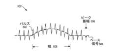
図5は、本発明の実施形態に係る、外部励起信号に応じて、電極212(又は216)からの例としての信号500を示している。図示のとおり、信号500は、ベース信号504に重畳されたパルス502を含んでもよく、ここでパルス502は、心臓から海綿体を通じる血流によって生じた、2つの電極212(又は216)間の身体の電気インピーデンスの変動を示している。実施形態において、ベース信号504は、パルス502間の信号の部分を表していてもよい。実施形態において、ベース信号504は、励起信号に応じた、幅508とピーク振幅506とを有する変化を示し、ここで幅及びピーク振幅は、外部励起信号の種別、外部励起信号の印加される箇所など、種々のパラメータに応じて変動し得る。 FIG. 5 shows an
実施形態において、幅508の最低閾値は、高周波数におけるノイズをフィルタするように規定されてもよい。例えば、装置210は、幅508が最低閾値を下回る場合、ベース信号の変動を無視してもよい。実施形態において、装置210は、外部励起信号を印加する前後に2つのベース信号を取得してもよく、ベース信号を比較して、海綿体が外部励起信号に応答するか否かを判定してもよい。例えば、励起信号がRPプロセス後に印加されるとき、海綿体神経がRPプロセス中に不注意に切断された場合、ピーク振幅がゼロに接近する。他の例において、励起信号がRPプロセス後に印加されるとき、海綿体神経が無傷であれば、幅及びピーク振幅は、RPプロセス前のものと同様となるであろう。 In embodiments, a minimum threshold for width 508 may be defined to filter noise at high frequencies. For example,
実施形態において、ピーク振幅は、プローブ電極402が配置されるポイントが海綿体神経に近づくほど大きくなる。実施形態において、ピーク振幅506の閾値は、事前に設定されてもよい。そして、ピーク振幅が、励起信号に応じて、事前に規定した閾値を超過したとき、装置210は、手術用器具412が海綿体神経に近過ぎると判定してもよく、スピーカ312は、執刀医が手術用器具412を配置したポイントで組織を切断することがないように、執刀医に警告信号を発出してもよい。 In embodiments, the peak amplitude is greater the closer the point where the probe electrode 402 is placed to the cavernous nerve. In embodiments, the threshold for peak amplitude 506 may be preset. Then, when the peak amplitude exceeds a pre-defined threshold in response to the excitation signal,
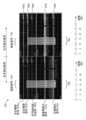
図6は、本発明の実施形態に係る、SSR CC-EMG信号を含む、例としてのスクリーンショット600を示している。図示のとおり、スクリーンショット600の左半分は、患者の左手側に搭載された電極からの信号を示しており、スクリーンショット600の右半分は、患者の右手側に搭載された電極からの信号を示している。より具体的には、プロット602a、604a、606a、618a、及び620aは、各々、左手の一対の表面電極217、左足の一対の表面電極219、外肛門括約筋の左手側に挿入された一対の針電極214、陰茎209の左手側皮膚の一対の表面電極212、及び左海綿体に挿入された一対の針電極216からの信号である。同様に、プロット602b、604b、606b、618b、及び620bは、各々、右手の一対の表面電極217、右足の一対の表面電極219、外肛門括約筋の右手側に挿入された一対の針電極214、陰茎209の右手側皮膚の一対の表面電極212、及び右海綿体に挿入された一対の針電極216からの信号である。 FIG. 6 shows an
スクリーンショット600におけるプロットは、交感神経皮膚反応(SSR)海綿体筋電図(CC-EMG)を表し、ここでSSR CC-EMGは、患者の足首の一対の電極220に印加された励起信号に応じた海綿体電気活性を示している。スクリーンショット600において、プロット602a、602b、604b、606a、606b、618b、620a、及び620bは、いくつかの励起信号630が左足首の一対の電極220に印加されたときの、対応電極からの信号である。図示のとおり、矢印640で示されるプロット620aの種々の部分は、励起信号630に応じた左海綿体の海綿体電気活性が期待される箇所を示しており、矢印642で示されるプロット620bの種々の部分は、励起信号630に応じた右海綿体の海綿体電気活性が期待される箇所を示している。CC-EMG信号が、矢印644によって示されたポイントにおいて明確な海綿体電気活性を示すとき、装置210は、陰茎海綿体が適正に機能していると判定してもよい。実施形態において、図5との関連で検討したとおり、装置210は、プロット620bのベース信号における変化を測定してもよく、矢印644におけるベース信号の幅及びピーク振幅が事前に設定した閾値を超過する場合、右側海綿体が適正に機能していると判定してもよい。 The plot in
実施形態において、1つ以上の皮下針電極215が患者の矢状面(Cz-Fzモンタージュ)内で頭皮に挿入され、装置210に電気的に連結されてもよい。実施形態において、接触刺激の結果として生じた電気活性を測定するため、装置210は、表面電極212に電気励起信号を印加し、励起信号に応じた電極215からの電気信号(すなわち、陰部体性感覚誘発電位信号)を測定してもよい。RPプロセス中、装置210は、電極212に電気励起信号を反復的に送信し、患者の体性感覚システム機能をモニタリングするため、電極215からの電気信号を確認してもよい。 In embodiments, one or more
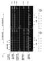
図7は、本発明の実施形態に係る、陰部体性感覚誘発電位(SEP)信号を含む、例としてのスクリーンショット700を示している。実施形態において、スクリーンショット700内のプロットは、患者の冠状皮膚に挿入された皮下針電極215からの電気信号を示している。 FIG. 7 shows an
図示のとおり、各陰部SEP信号は、表面電極212に印加された電気励起信号によって引き出された一定の待ち時間において、明確且つ一貫した応答を示している。図7のプロットは、異なる時間に電気励起信号を印加し、各SEP信号が時間軸の原点で開始するように、時間軸上に得られた陰部SEP信号をシフトすることによって、生成されることに留意されたい。 As shown, each pubic SEP signal exhibits a distinct and consistent response at constant latency elicited by the electrical excitation signal applied to
実施形態において、陰部SEPの存在と一貫性とは、患者の感覚神経が無傷であることを意味している。実施形態において、感覚神経系への潜在的な損傷をモニタリングするために、RPプロセス中、規則的に、陰部SEP信号が反復測定されてもよい。 In embodiments, the presence and consistency of pudendal SEP means that the patient's sensory nerves are intact. In embodiments, pudendal SEP signals may be repeatedly measured periodically during the RP process to monitor potential damage to the sensory nervous system.
図8は、本発明の実施形態に係る、交感神経皮膚反応(SSR)海綿体筋電図(CC-EMG)信号を含む、例としてのスクリーンショット800を示している。スクリーンショット800のプロットは、スクリーンショット600のプロットと同様であり、励起信号830が左手首の表面電極218に印加される点で異なる。スクリーンショット800のプロット81a、818b、820a、及び820bは、SSR CC-EMG信号を表しており、ここでSSR CC-EMG信号は、励起信号830に応じた血管運動活性からの海綿体のインピーダンスの変化を反映する。図示のとおり、矢印840(及び842)は、励起信号830に応じた左(及び右)海綿体の海綿体電気活性が期待される箇所を示している。SSR CC-EMG信号が矢印851及び853によって示される箇所で明確な海綿体電気活性を示すため、装置210は、陰茎海綿体が適正に機能することを判定してもよい。 FIG. 8 shows an
図9は、本発明の実施形態に係る、種々の電極からの信号を含む、例としてのスクリーンショット900を示している。図9において、プロット902a(又は902b)、904a(又は904b)、906a(又は906b)、918a(又は918b)、及び920a(又は920b)は、各々、左(又は右)手の一対の表面電極217、左(又は右)足の一対の表面電極219、左(又は右)外肛門括約筋に挿入された一対の針電極214、陰茎209の左(又は右)手側皮膚の一対の表面電極212、及び左(又は右)海綿体216に挿入された一対の針電極からの信号である。 FIG. 9 shows an
図9において、電気励起パルス列(正弦波又は方形波など)930は、5.1Hzで10秒間、腹腔鏡420(又は430)の先端電極422(又は432)に印加され、先端は、右海綿体神経を含む可能性の高い組織上に配置されてもよい。また、電気パルス列930は、膀胱頸部切断後、すなわち、前立腺を膀胱及び前立腺周辺の組織から切断(分離)した後、且つ、前立腺が患者の体内から完全に摘出される前に、印加されてもよい。図示のとおり、プロット918a(及び920a)の部分940は、陰茎の左手側表面(及び左海綿体)の電極212(及び216)間の身体のインピーダンス変化を示しており、プロット918b(及び920b)の部分942は、陰茎の右手側表面(及び右海綿体)の電極212(及び216)間の身体のインピーダンス変化を示している。実施形態において、4つのプロット918a、918b、920a、及び920bのベース信号は、各々、部分940及び942で十分に大きなピーク振幅及び幅を示しているため、装置210は、電極212(及び216)間の身体のインピーダンス変化が明らかであり、海綿体神経は無傷であると判定してもよい。 In FIG. 9, an electrical excitation pulse train (such as a sine wave or square wave) 930 is applied to the tip electrode 422 (or 432) of the laparoscope 420 (or 430) for 10 seconds at 5.1 Hz, and the tip is applied to the right corpus cavernosum. It may be placed over tissue likely to contain nerves. The electrical pulse train 930 is also applied after bladder neck transection, i.e., after cutting (separating) the prostate from the bladder and surrounding tissue, and before the prostate is completely removed from the patient's body. good too. As shown,
実施形態において、励起信号930に応じたプロット918a(918b、920a、又は920b)のベース信号の変化を使用して、先端422(又は432)の箇所と海綿体神経208との間の距離を判定することにより、海綿体神経のマッピングを行ってもよい。この距離を判定するため、信号生成器304は、励起信号930の振幅をベース信号が何らの変化も示さない値まで漸進的に低減しつつ、先端422(又は432)に励起信号を反復的に送信してもよい。この値は、海綿体神経を励起する最低閾値であるため、装置210は、この閾値を使用して、先端422(又は432)の箇所と海綿体神経208との間の距離を判定する。実施形態において、メモリ314は、事前に用意された、閾値と距離との間の相関に関する情報を記憶してもよく、装置210は、この情報にアクセスすることで、現在測定されている最低閾値に対応する距離を判定してもよい。装置210は、前立腺206周辺の組織の異なる箇所に先端422を配置しつつ、このプロセスを反復することで、前立腺付近の海綿体神経をマッピングしてもよい。 In an embodiment, the change in base signal of plot 918a (918b, 920a, or 920b) in response to excitation signal 930 is used to determine the distance between the location of tip 422 (or 432) and cavernous nerve 208. Mapping of the corpus cavernosum nerve may be performed by To determine this distance, signal generator 304 repeatedly applies an excitation signal to tip 422 (or 432) while progressively reducing the amplitude of excitation signal 930 to a value at which the base signal exhibits no change. You may send.
実施形態において、執刀医は、RPプロセス中、腹腔鏡410を使用してもよい。このような場合、信号930と同様の励起パルス列が、先端412を通じて組織のポイントに印加されてもよい。励起信号に応じた信号918a(918b、920a、又は920b)のピーク振幅の大きさが閾値を超過する場合、装置210は、当該ポイントと海綿体神経208との間の距離が近過ぎると判定し、執刀医が手術用器具412の先端で組織を切断しないように、執刀医に警告信号を発出してもよい。 In embodiments, the surgeon may use the
図10は、本発明の実施形態に係る、種々の電極からの信号を含む、例としてのスクリーンショット1000を示している。図10において、プロット1002a(又は1002b)、1004a(又は1004b)、1006a(又は1006b)、1018a(又は1018b)、及び1020a(又は1020b)は、各々、左(又は右)手の一対の表面電極217、左(又は右)足の一対の電極219,外肛門括約筋の左(又は右)手側に挿入された一対の針電極214、陰茎209の左(又は右)手側の一対の表面電極212、及び左(又は右)海綿体に挿入された一対の針電極216からの信号である。 FIG. 10 shows an
図10において、電気励起パルス列1030は、5.1Hzにて10秒間、腹腔鏡420(又は430)の先端電極422(又は432)を通じて印加され、先端は、左海綿体歯茎を含む可能性の高い組織上に配置されている。また、電気パルス列1030は、膀胱頸部切断後、すなわち、前立腺を膀胱及び前立腺周辺組織から切断(分離)した後、且つ、前立腺を患者の体内から完全に摘出した後に印加されてもよい。図示のとおり、プロット1018a(及び1020a)の部分1040は、陰茎の左手側(及び左海綿体)の電極212間の身体のインピーダンス変化を示しており、プロット1018b(及び1020b)の部分1042は、陰茎の右手側(及び右海綿体)の電極212間の身体のインピーダンス変化を示している。 In FIG. 10, an electrical excitation pulse train 1030 is applied for 10 seconds at 5.1 Hz through tip electrode 422 (or 432) of laparoscope 420 (or 430), the tip likely containing the left corpus cavernosum. placed on the organization. The electrical pulse train 1030 may also be applied after a bladder neck cut, ie, after cutting (separating) the prostate from the bladder and surrounding tissue, and after removing the prostate completely from the patient's body. As shown,
プロット1018a(及び1020a)の部分1040は、陰茎の左手側(及び左海綿体)の電極212(及び216)間の身体のインピーダンス変化を示している。プロット1018b(及び1020b)の部分1042は、陰茎の右手側(及び右海綿体)の電極212(及び216)間の身体のインピーダンス変化を示している。実施形態において、4つのプロット1018a、1018b、1020a、及び1020bのベース信号は、各々、十分に大きなピーク振幅及び幅を示すため、装置210は、電極212(及び216)間の身体のインピーダンス変化は明らかであり、左海綿体神経が無傷であると判定してもよい。
図9(及び図10)中の励起パルス列930(及び1030)は、右海綿体神経付近の組織のポイントに印加されてもよいことに留意されたい。実施形態において、プロット918、920、1018,及び1020が励起信号に応じて同様の変化を示す場合、装置210は、右海綿体神経が無傷であると判定してもよい。 Note that the excitation pulse train 930 (and 1030) in Figures 9 (and 10) may be applied to a point of tissue near the right cavernous nerve. In embodiments, if plots 918, 920, 1018, and 1020 exhibit similar changes in response to the excitation signal,
図11は、本発明の実施形態に係る、種々の電極からの信号を含む、例としてのスクリーンショット1100を示している。図11において、プロット1102a(又は1102b)、1104a(又は1104b)、1106a(又は1106b)、1118a(又は1118b)、及び1120a(又は1120b)は、各々、左(又は右)手の一対の表面電極217、左(又は右)の一対の表面電極219、外肛門括約筋の左(又は右)手側に挿入された一対の針電極214、陰茎209の左(又は右)手側皮膚の一対の表面電極212、及び左(又は右)海綿体に挿入された一対の針電極216からの信号である。 FIG. 11 shows an
図11において、2セットの励起電極パルス1130及び1132は、代替の手法で反復印加される。第1のセット(パルス列)の電気パルス1130は、5.1Hzにて10秒間、腹腔鏡420(又は430)の先端電極422(又は432)に印加され、先端電極422(又は432)は、右海綿体神経を含む可能性の高い組織上に配置されている可能性がある。第2のセット(パルス列)の電気パルス1132は、組織の同一箇所において、2.0Hzにて10秒間、同一の先端電極に印加されてもよい。実施形態において、これら2つの電気パルス列1130及び1132は、前立腺が患者の体内から完全に摘出された後に、代替の手法で反復印加されてもよい。 In FIG. 11, two sets of
図11では、例示のため、信号1102、1104、及び1106の時間軸が信号1118及び1120の時間軸に対してシフトされている。信号1140及び1144は、低周波励起信号1132に応じて生成され、信号1142及び1146は、励起信号1130に応じて生成される。また、例示のため、2セットの信号1140及び1142(並びに、1144及び1146)のみが時間軸上に示されている。しかしながら、当業者にとって、電極212及び216が、反復信号1130及び1132に応じて、信号1140、1142,1144,及び1146と同様の信号を反復的に生成することは明らかであるはずである。 In FIG. 11, the time axes of signals 1102, 1104, and 1106 are shifted with respect to the time axes of signals 1118 and 1120 for purposes of illustration.
信号部分1140、1142,1144,及び1146に示されるとおり、海綿体は、高周波及び低周波の双方の励起信号1130及び1132に応答する。実施形態において、2つのプロット1118b及び1120bのベース信号は各々、十分に大きなピーク振幅及び幅を示すため、装置210は、電極212(又は216)間の身体のインピーダンス変化が明らかであり、右海綿体神経がRPプロセス中に損傷されていないと判定してもよい。 As shown in
図12は、本発明の実施形態に係る、種々の電極からの信号を含む、例としてのスクリーンショット1200を示している。図12において、プロット1202a(又は1202b)、1204a(又は1204b)、1206a(又は1206b)、1218a(又は1218b)、及び1220a(又は1220b)は、各々、左(又は右)手の一対の表面電極21、左(又は右)足の一対の表面電極219、外肛門括約筋の左(又は右)手側に挿入された一対の針電極214、陰茎209の左(又は右)手側皮膚の一対の表面電極212、及び左(又は右)海綿体に挿入された一対の針電極からの信号である。 FIG. 12 shows an
図12は、図11と同様であり、2つの電気励起パルス列1230(5,1Hzにて10秒間)及び1232(2.0Hzにて10秒間)が、腹腔鏡420(又は430)の先端電極422(又は432)を通じて、左側海綿体神経を含む可能性の高い組織に、反復的且つ交互に印加される点が異なる。プロット1218a及び1220aの部分1240及び1242は、陰茎の左手側(及び左海綿体)の電極212(及び216)間の身体のインピーダンス変化を示している。また、プロット1218b及び1220bの部分1244及び1246は、陰茎の右手側(及び右海綿体)の電極212(及び216)からの電極間の身体のインピーダンス変化を示している。 FIG. 12 is similar to FIG. 11, with two electrical excitation pulse trains 1230 (5.1 Hz for 10 seconds) and 1232 (2.0 Hz for 10 seconds) applied to the tip electrode 422 of the laparoscope 420 (or 430). (or 432) to tissues likely to contain the left cavernous nerve, repetitively and alternately.
図12に示されるとおり、海綿体は、低周波励起信号1232よりも、高周波励起信号1230でより大きな応答を示す。実施形態において、2つのプロット1218a及び1220aのベース信号は、各々、十分に大きなピーク振幅及び幅を示すため、装置210は、電極212(又は216)間の身体のインピーダンス変化が明らかであり、左海綿体神経はRPプロセス中に損傷していないと判定してもよい。 As shown in FIG. 12, the corpus cavernosum exhibits a greater response to high
図11及び図12の電気励起信号は、患者の体内から前立腺を摘出する前、又はその途中に印加されてもよいことに留意されたい。装置210は、図11及び図12と同様に信号を解析することにより、右及び左の海綿体神経が前立腺摘出プロセス中に損傷したか否かを判定してもよい。 Note that the electrical excitation signals of FIGS. 11 and 12 may be applied prior to or during removal of the prostate from the patient's body.
図13は、本発明の実施形態に係る、種々の電極からの信号を含む、例としてのスクリーンショット1300を示している。図13において、プロット1302a(又は1302b)、1304a(又は1304b)、1306a(又は1306b)、1318a(又は1318b)、及び1320a(又は1320b)は、各々、左(又は右)手の一対の表面電極217、左(又は右)足の一対の表面電極219、外肛門括約筋の左(又は右)手側に挿入された一対の針電極214、陰茎209の左(又は右)手側皮膚の一対の表面電極212、及び左(又は右)海綿体に挿入された一対の針電極216からの信号である。 FIG. 13 shows an
図13において、電気励起パルス列1330は、2.0Hzにて10秒間、腹腔鏡420(又は430)の先端電極422(又は432)を通じて印加され、先端は、骨盤内壁上の、NVB(すなわち、海綿体神経)からある程度離間した箇所に配置されてもよい。図示のとおり、プロット1318及び130には、電極212(又は216)間の身体のインピーダンス変化を示しておらず、これは、海綿体神経が先端プローブの配置されたポイント付近に配置されていないことを含意する。 In FIG. 13, an electrical
実施形態において、腹腔鏡420(又は430)の先端電極に印加された電気励起パルス列は、2.0~50.0Hzの周波数範囲と、10秒以上の持続時間を有してもよいが、他の周波数範囲及び持続時間を使用して図9~13の信号を生成してもよい。 In embodiments, the electrical excitation pulse train applied to the tip electrode of the laparoscope 420 (or 430) may have a frequency range of 2.0-50.0 Hz and a duration of 10 seconds or longer, although other may be used to generate the signals of FIGS. 9-13.
図9~図13において、双極電極422(又は432)を使用して、前立腺付近の組織に励起信号を印加している。しかしながら、当業者にとって、電極402又は412が電極422の代わりに使用されてもよいことは明らかであるはずである。 9-13, a bipolar electrode 422 (or 432) is used to apply an excitation signal to tissue near the prostate. However, it should be clear to those skilled in the art that electrode 402 or 412 may be used in place of electrode 422. FIG.
図14は、本発明の実施形態に係る、SSR CC-EMG信号を含む、例としてのスクリーンショット1400を示している。図14において、電気励起信号1430は、左手首の表面電極218を通じて印加され、プロット1402a(又は1402b)、1404a(又は1404b)、1406a(又は1406b)、1418a(又は1418b)、及び1420a(又は1420b)は、各々、左(又は右)手の一対の表面電極217、左(又は右)足の一対の表面電極219、外肛門括約筋の左(又は右)手側に挿入された一対の針電極214、陰茎209の左(又は右)手側皮膚の一対の表面電極212、及び左(又は右)海綿体に挿入された一対の針電極216からの信号である。 FIG. 14 shows an
スクリーンショット1400のプロットは、スクリーンショット800のプロットと同様であり、励起信号1430がRPプロセス完了後に印加される点で異なる。図14において、プロット1420aの矢印1440によって示される種々の部分は、励起信号1430に応じた左海綿体の海綿体電気活性を示しており、プロット1420Bの矢印1432によって示される種々の部分は、右海綿体の海綿体電気活性を示している。実施形態において、装置210は、矢印1440によって示される箇所の信号1420aと、矢印1442によって示される箇所の信号1420bとに基づき、手首皮膚への励起信号に応じた、海綿体の自律神経系の血管運動機能が、RPプロセスを通じて保存されていることを判定してもよい。 The plot of
図15は、本開示の実施形態に係る、RPプロセス中に海綿体神経のマッピング及び保存を行う例示的なプロセス1500のフローチャートを示している。ステップ1502において、少なくとも一対の電極212(及び/又は216)が陰茎209に設置されてもよい。ステップ1504において、前立腺など、海綿体神経が組織内に存在する可能性の高い標的臓器付近の組織(又はNVB)のポイントに先端電極422が接触するように、先端電極422(又は432)を備えた腹腔鏡420(又は430)が患者の体内に挿入されてもよい。実施形態において、標的臓器とは、執刀医が手術処置を実施する内部臓器をいう。そしてステップ1506にて、励起信号が先端電極を通じて当該ポイントに印加される。次に、励起信号に応じて、一対の電極212(又は216)からの信号の変化が測定されるが、ここで一対の電極212(又は216)からの信号の変化は、一対の電極212(又は216)の電極間の身体のインピーダンスの変化に見合ったものである。すなわち、この変化は、陰茎の勃起機能に関連する。実施形態において、励起信号は、2.0~10.0Hzの周波数範囲と、10秒以上の持続時間とを有してもよい電気パルス列(正弦波又は方形波など)を含んでもよい。 FIG. 15 illustrates a flowchart of an
ステップ1510において、一対の電極212(又は216)からの信号の変化に基づき、当該組織上のポイントと海綿体神経との間の距離が判定されてもよい。実施形態において、一対の電極212(又は216)からの信号の変化のピーク振幅の大きさが閾値を超過する場合、当該組織の部分と海綿体神経との距離が事前に設定した値より短いと判定されてもよい。代替実施形態において、海綿体神経を励起する最低閾値を使用して、この距離を判定してもよい。信号生成器304は、ベース信号が何らの変化を示さない値まで励起信号の振幅が漸進的に低減される間、先端422(又は432)に励起信号を反復的に送信してもよい。この値は、海綿体神経を励起する最低閾値であるため、装置210は、この閾値を使用して、先端422(又は432)の位置と海綿体神経208との間の距離を判定する。実施形態において、メモリ314は、事前に用意された、この閾値と距離との間の相関に関する情報を記憶してもよく、装置210(より具体的には、プロセッサ302)は、この相関情報にアクセスして、現在測定されている最低閾値に対応する距離を判定してもよい。 At
任意で、ステップ1512において、先端電極がナイフなどの手術用器具を備え、当該ポイントと海綿体神経との間の距離が事前に設定した値より短い場合、執刀医に警告信号を発出してもよい。ステップ1514において、標的臓器付近の海綿体神経がマッピングされるように、組織の異なるポイントに先端電極を配置しつつ、ステップ1504~1510が反復されてもよい。 Optionally, in
図2~図15において、海綿体神経のマッピング、モニタリング、及び保存を行うためのシステム及び方法について、RPプロセスとの関連で説明している。しかしながら、当業者にとって、このシステム及び方法が、骨盤領域の任意の好適な種別の手術に適用されてよいことは明らかなはずである。例えば、直腸癌の手術中、執刀医は、直腸付近に配置された海綿体神経を損傷してしまう可能性があるため、直腸付近の海綿体神経のマッピング及びモニタリングに、図2~図15との関連で説明したシステム及び方法を使用してもよい。 2-15, systems and methods for mapping, monitoring, and preserving cavernous nerves are described in the context of the RP process. However, it should be apparent to those skilled in the art that the system and method may be applied to any suitable type of surgery in the pelvic region. For example, during surgery for rectal cancer, the surgeon may injure the cavernous nerves located near the rectum, so mapping and monitoring the cavernous nerves near the rectum may be performed using FIGS. may be used.
図10、11、12、及び13は、腹腔鏡420(又は430)の先端電極422(又は432)を通じて印加された電気励起パルスに応じた、種々のセンサからの信号を示している。しかしながら、電気励起パルスは、他の種別の電極を通じて印加されてもよい。例えば、海綿体神経が観血的手術中に損傷しているか否かを確認するため、執刀医は、観血的手術中、海綿体神経を含む可能性の高い組織に電気励起パルスを印加してもよい。このような場合、先端電極422(又は432)は、腹腔鏡の遠位端に必ずしも装着されなくてもよく、すなわち、腹腔鏡420(又は430)は、先端電極422(又は432)を備えた好適な装置に置き換えられてもよい。 Figures 10, 11, 12, and 13 show signals from various sensors in response to electrical excitation pulses applied through tip electrode 422 (or 432) of laparoscope 420 (or 430). However, the electrical excitation pulse may be applied through other types of electrodes. For example, to determine whether the cavernous nerve is damaged during open surgery, the surgeon applies electrical excitation pulses to tissue likely to contain the cavernous nerve during open surgery. may In such cases, tip electrode 422 (or 432) may not necessarily be attached to the distal end of the laparoscope, i.e., laparoscope 420 (or 430) may be equipped with tip electrode 422 (or 432). Any suitable device may be substituted.
実施形態において、1つ以上の演算システムが、本明細書に記した方法、機能、及び/又は、動作のうちの1つ以上を実施するように構成されてもよい。本明細書に記した方法、機能、及び/又は、動作のうちの少なくとも1つ以上を実装するシステムは、少なくとも1つの演算システム上で動作するアプリケーション(単数又は複数)を備えてもよい。演算システムは、1つ以上のコンピュータと、1つ以上のデータベースとを備えてもよい。コンピュータシステムは、単一システム、分配システム、クラウドベースコンピュータシステム、又はこれらの組み合わせであってもよい。 In embodiments, one or more computing systems may be configured to perform one or more of the methods, functions and/or actions described herein. A system implementing at least one or more of the methods, functions and/or actions described herein may comprise application(s) running on at least one computing system. A computing system may comprise one or more computers and one or more databases. A computer system may be a single system, a distributed system, a cloud-based computer system, or a combination thereof.
本発明は、非限定的に、ラップトップコンピュータ、デスクトップコンピュータ、及びサーバを含む、データ処理の可能な任意の指示実行/演算装置又はシステムにおいて実装されてもよいことに留意されたい。本発明はまた、他の演算装置及びシステムに実装されてもよい。さらに、本発明の態様は、ソフトウェア(ファームウェアを含む)、ハードウェア、又はこれらの組み合わせを含む、広範に及ぶ手法で実装されてもよい。例えば、本発明の種々の態様を実施する機能が、具体的な論理要素、1つ以上のアプリケーション専用集積回路(ASIC)、及び/又は、プログラム制御プロセッサを含む、広範に及ぶ手法で実装された構成要素で実施されてもよい。これらの項目が実装される方法は、本発明にとって重要な意味を持つものでない。 Note that the present invention may be implemented in any instruction-executing/computing device or system capable of processing data, including, but not limited to, laptop computers, desktop computers, and servers. The invention may also be implemented in other computing devices and systems. Moreover, aspects of the invention may be implemented in a wide variety of ways, including software (including firmware), hardware, or a combination thereof. For example, the functionality implementing various aspects of the invention may be implemented in a wide variety of ways including specific logic elements, one or more application specific integrated circuits (ASICs), and/or program-controlled processors. It may be implemented in components. The manner in which these items are implemented is not material to the invention.
本発明の詳細について説明したが、一例としてのシステム1600は、本発明の1つ以上の態様を実施するために使用されてもよく、これについて、図16を参照してこれから説明する。図2の演算システム211(又は装置210)は、システム1600中に1つ以上の構成要素を備えてもよい。図16に示されるとおり、システム1600は、演算リソースを提供してコンピュータを制御する、中央処理装置(CPU)1601を備える。CPU1601は、マイクロプロセッサなどで実装されてもよく、グラフィックプロセッサ、及び/又は、数学的演算のための浮動小数点コプロセッサも備えてよい。システム1600はまた、システムメモリ1602を備えてもよく、これは、ランダムアクセスメモリ(RAM)及び読取専用メモリ(ROM)の形態であってもよい。 Having described the details of the present invention, an
図16に示されるとおり、多数のコントローラ及び周辺装置も設けられてよい。入力コントローラ1603は、キーボード、マウス、又はスタイラスなど、種々の入力装置1605に対するインタフェースを表す。スキャナコントローラ1605も設けられてよく、これは、スキャナ1606と通信する。システム1600はまた、各々、本発明の種々の態様を実装するプログラムの実施形態を含んでもよい、システム、ユーティリティ、及びアプリケーションを動作させる指示のプログラムを記録するために使用されてもよい、磁気テープ又はディスク、又は光学媒体などの記録媒体を含む、1つ以上の記憶装置1608とインタフェースを取るための記憶コントローラ1607も備えてよい。記憶装置1608はまた、処理済みデータ、又は、本発明に応じて処理されるデータを記憶するために使用されてもよい。システム1600は、ディスプレイ装置1611にインタフェースを提供するディスプレイコントローラ1609も備えてよく、これは、陰極線管(CRT)、薄膜トランジスタ(TFT)ディスプレイ、又はその他の種別のディスプレイであってもよい。システム1600はまた、プリンタ1613と通信するプリンタコントローラ1612も備えてよい。通信コントローラ1614は、1つ以上の通信装置1615とインタフェースを取ることにより、システム1600が、インターネット、イーサネットクラウド、FCoE/DCBクラウド、ローカルエリアネットワーク(LAN)、ワイドエリアネットワーク(WAN)、記憶領域ネットワーク(SAN)を含む種々のネットワークのうちの任意のものを通じて、又は、赤外線信号を含む、任意の好適な電磁気搬送信号を通じて、遠隔装置と接続できるようにする。 A number of controllers and peripherals may also be provided, as shown in FIG.
図示のシステムにおいて、すべての主要なシステム構成要素は、バス1616に接続されてもよく、これは、2つ以上の物理バスを表してもよい。しかしながら、種々のシステム構成要素が、互いに物理的に近接していてもよく、又は近接していなくてもよい。例えば、入力データ及び/又は出力データは、1つの物理的位置から他の位置に遠隔送信されてもよい。また、本発明の種々の態様を実施するプログラムが、ネットワークを通じて、遠隔位置(例えば、サーバ)からアクセスされてもよい。このようなデータ及び/又はプログラムは、非限定的に、ハードディスク、フロッピーディスク、及び磁気テープなどの磁気媒体、CD-ROM及びホログラフィックデバイスなどの光学媒体、磁気光学媒体、アプリケーション専用集積回路(ASIC)、プログラマブル論理装置(PLD)、フラッシュメモリ装置、並びにROM及びRAM装置など、プログラムコードを記憶するか、又は記憶して実行するように特別に構成されたハードウェア装置を含む、種々の機械可読媒体を通じて搬送されてもよい。 In the illustrated system, all major system components may be connected to
本発明の実施形態は、1つ以上のプロセッサ又は処理ユニットにステップを実施させる指示を備えた1つ以上の持続性コンピュータ可読媒体上で符号化されてもよい。1つ以上の持続性コンピュータ可読媒体は、揮発性及び非揮発性のメモリを備えなければならないことに留意されたい。ハードウェア実装又はソフトウェア/ハードウェア実装を含む、代替の実装も可能であることに留意されたい。ハードウェアで実装された機能は、ASIC、プログラマブルアレイ、デジタル信号処理回路などを使用して実現されてもよい。従って、いずれのクレーム中の「手段」という用語も、ソフトウェアおよびハードウェアによる実装の双方を網羅することが意図されている。同様に、本明細書中で使用される「コンピュータ可読媒体(単数又は複数)」という用語には、指示プログラムが組み込まれたソフトウェア及び/又はハードウェア、若しくはそれらの組み合わせが含まれる。これらの代替を考慮すると、図面及びそれに伴う説明は、当業者がプログラムコード(すなわち、ソフトウェア)を記述したり、及び/又は、必要な処理を実施する回路(すなわち、ハードウェア)を製作するのに必要とされる機能的情報を提供するものであることが理解されよう。 Embodiments of the invention may be encoded on one or more persistent computer-readable media with instructions that cause one or more processors or processing units to perform steps. Note that one or more persistent computer-readable media should include volatile and non-volatile memory. Note that alternative implementations are possible, including hardware implementations or software/hardware implementations. Hardware-implemented functions may be realized using ASICs, programmable arrays, digital signal processing circuits, and the like. Thus, the term "means" in any claims is intended to cover both software and hardware implementations. Similarly, the term "computer-readable medium(s)" as used herein includes software and/or hardware embodying an instruction program, or a combination thereof. With these alternatives in mind, the drawings and accompanying descriptions are intended to help those skilled in the art to write program code (i.e., software) and/or construct circuitry (i.e., hardware) to perform the required processing. It will be appreciated that it provides the functional information required for
本発明の実施形態はさらに、種々のコンピュータ実装動作を実施するためのコンピュータコードを有した、持続性の有形コンピュータ可読媒体を備えた、コンピュータ製品に関連してもよい。当該媒体及びコンピュータコードは、本発明の目的に合わせて特別に設計及び構築されたものであってもよく、或いは、関連技術の当業者にとって既知であるか、又は利用可能である種別のものであってもよい。有形コンピュータ可読媒体の非限定的な例として、ハードディスク、フロッピーディスク、及び磁気テープなどの磁気媒体、CD-ROM及びホログラフィックデバイスなどの光学媒体、磁気光学媒体、及び、アプリケーション専用集積回路(ASIC)、プログラマブル論理装置(PLD)、フラッシュメモリ装置、並びにROM及びRAM装置など、プログラムコードを記憶するか、又は記憶して実行するように特別に構成されたハードウェア装置が挙げられる。コンピュータコードの例として、コンパイラによって作成されるような機械コード、翻訳機を使用してコンピュータで実行されるより高レベルのコードを含んだファイルが挙げられる。本発明の実施形態は、処理装置によって実行されるプログラムモジュール中にあってもよい、機械実行可能な指示として、全部又は一部、実装されてもよい。プログラムモジュールの例として、ライブラリ、プログラム、ルーティン、オブジェクト、コンポーネント、及びデータ構造が挙げられる。分散演算環境では、プログラムモジュールは、局所、遠隔、又はそれら双方のセッティングで物理的に設定されてもよい。 Embodiments of the present invention may also relate to computer products with a persistent, tangible computer-readable medium that have computer code thereon for performing various computer-implemented operations. Such media and computer code may be those specially designed and constructed for the purposes of the present invention, or they may be of the kind known or available to those of skill in the relevant arts. There may be. Non-limiting examples of tangible computer-readable media include magnetic media such as hard disks, floppy disks, and magnetic tapes, optical media such as CD-ROMs and holographic devices, magneto-optic media, and application-specific integrated circuits (ASICs). , programmable logic devices (PLDs), flash memory devices, and ROM and RAM devices that store or are specially configured to store and execute program code. Examples of computer code include machine code, such as produced by a compiler, and files containing higher level code that are executed by a computer using a translator. Embodiments of the invention may be implemented, in whole or in part, as machine-executable instructions, which may be in program modules to be executed by a processing device. Examples of program modules include libraries, programs, routines, objects, components, and data structures. In a distributed computing environment, program modules may be physically located in local, remote, or both settings.
当業者は、いずれの演算システム又はプログラミング言語も本発明の実施に当たって重要な意味をもつものでないことを認識するであろう。当業者はまた、前述の多数の要素が、サブモジュールとなるように物理的及び/又は機能的に分離されてもよく、又は互いに組み合わせられてもよいことも認識するであろう。 Those skilled in the art will recognize that no particular operating system or programming language is critical to the practice of the present invention. Those skilled in the art will also recognize that many of the aforementioned elements may be physically and/or functionally separated into sub-modules, or combined with each other.
当業者にとって、以上の例及び実施形態は、一例であり、本発明の範囲を限定するものでないことを理解するであろう。当業者が本明細書を読解し、図面を検討すれば明らかとなるすべての入替、改良、同等物、組み合わせ、及び改善が本発明の真の趣旨及び範囲に包含されることが意図されている。
Those skilled in the art will appreciate that the above examples and embodiments are examples and do not limit the scope of the present invention. All alterations, modifications, equivalents, combinations and improvements that will become apparent to those skilled in the art upon reading this specification and studying the drawings are intended to be encompassed within the true spirit and scope of the invention. .
Claims (7)
Translated fromJapanese1つ以上のプロセッサと、
前記1つ以上のプロセッサと通信可能に連結され、1つ以上の指示シーケンスを記憶するメモリと、を備え、前記1つ以上の指示シーケンスは、1つ以上のプロセッサによる実行時、
(a)臓器付近の組織の一部に接触するように構成された電極に、励起信号を印加することと、
(b)前記励起信号に応じて、陰茎に装着されるように構成された一対の電極からの信号の変化を測定することであって、前記信号の変化は、前記陰茎の勃起機能に関連することと、
(c)前記一対の電極からの前記信号の変化に基づき、前記組織の一部と、前記臓器付近の海綿体神経との間の距離を判定することと、
を含む構成であって、
前記ステップ(c)は、
前記励起信号の振幅が、前記ステップ(b)で測定されたセンサ信号が変化しない値まで漸進的に減少する間、前記ステップ(a)及び(b)を反復することと、
前記値に基づき、そのポイントと、前記臓器付近の前記海綿体神経との間の距離を判定することと、
センサ信号の変化のピーク振幅を測定することと、
前記ピーク振幅が閾値を超過した場合、前記距離が事前に設定した範囲内であると判定することと、
を備え、
前記励起信号は、2~10Hzの範囲の周波数と、10秒以上の持続時間とを有するパルス列を含み、
前記メモリは、1つ以上の指示シーケンスをさらに記憶し、前記プロセッサによる実行時、前記組織の異なる箇所に先端を配置しつつ、前記ステップ(a)~(c)を反復することにより、前記臓器付近の前記海綿体神経をマッピングすることを含むステップを実施させることを含む、
ステップが実施されるシステム。A system for mapping cavernous nerves near an organ, comprising:
one or more processors;
a memory communicatively coupled to the one or more processors and storing one or more sequences of instructions, the one or more sequences of instructions, when executed by the one or more processors,
(a) applying an excitation signal to an electrode configured to contact a portion of tissue near the organ;
(b) measuring a change in signal from a pair of electrodes configured to be attached to the penis in response to said excitation signal, said signal change being related to erectile function of said penis; and
(c) determining a distance between the portion of tissue and a cavernous nerve near the organ based on changes in the signal from the pair of electrodes;
A configuration comprising
The step (c) includes
repeating steps (a) and (b) while the amplitude of the excitation signal progressively decreases to a value where the sensor signal measured in step (b) does not change;
determining a distance between the point and the cavernous nerve near the organ based on the value;
measuring the peak amplitude of the change in the sensor signal;
determining that the distance is within a preset range if the peak amplitude exceeds a threshold;
with
said excitation signal comprises a pulse train having a frequency in the range of 2-10 Hz and a duration of 10 seconds or more;
The memory further stores one or more sequences of instructions which, when executed by the processor, cause the organ to repeat steps (a)-(c) while placing the tip at different locations on the tissue. causing a step including mapping the cavernous nerve in the vicinity to be performed;
The system in which the steps are performed.
前記メモリは、1つ以上の指示シーケンスをさらに記憶し、前記1つ以上のプロセッサによる実行時、
前記距離が前記事前に設定された範囲内であれば、前記スピーカに警告信号を発出させることを含むステップを実施させることを含む、請求項1に記載のシステム。Equipped with additional speakers,
The memory further stores one or more sequences of instructions, which when executed by the one or more processors:
2. The system of claim 1, comprising causing the speaker to perform a step including issuing a warning signal if the distance is within the preset range.
前記メモリは、1つ以上の指示シーケンスをさらに記憶し、前記1つ以上のプロセッサによる実行時、
前記距離が前記事前に設定された範囲内であれば、前記ディスプレイに警告信号を表示させることを含むステップを実施させることを含む、請求項1に記載のシステム。Equipped with an additional display,
The memory further stores one or more sequences of instructions, which when executed by the one or more processors:
2. The system of claim 1, comprising causing a step including displaying a warning signal on the display if the distance is within the preset range.
前記電極は、腹腔鏡の先端に配置され、前記腹腔鏡は、前記ロボティック手術システムで操作される請求項1に記載のシステム。further comprising a robotic surgical system electrically coupled to said system;
2. The system of claim 1, wherein the electrodes are positioned on the distal end of a laparoscope and the laparoscope is manipulated with the robotic surgical system.
(a)臓器付近の組織の一部に接触するように構成された電極に、励起信号を印加することと、
(b)前記励起信号に応じて、陰茎に設置されるように構成された一対の電極からの信号の変化を測定することであって、前記信号の変化は、前記陰茎の勃起機能に関連することと、
(c)前記一対の電極からの前記信号の変化に基づき、前記組織の一部と、前記臓器付近の海綿体神経との間の距離を判定することと、
を含むステップを実施させる1つ以上の指示シーケンスを備える構成であって、
前記ステップ(c)は、
前記励起信号の振幅が、前記ステップ(b)で測定されたセンサ信号が変化しない値まで漸進的に減少する間、前記ステップ(a)及び(b)を反復することと、
前記値に基づき、そのポイントと、前記臓器付近の前記海綿体神経との間の距離を判定することと、
センサ信号の変化のピーク振幅を測定することと、
前記ピーク振幅が閾値を超過した場合、前記距離が事前に設定した範囲内であると判定することと、
を備え、
前記励起信号は、2~10Hzの範囲の周波数と、10秒以上の持続時間とを有するパルス列を含み、
1つ以上の指示シーケンスをメモリに記憶し、前記組織の異なる箇所に先端を配置しつつ、前記ステップ(a)~(c)を反復することにより、前記臓器付近の前記海綿体神経をマッピングすることを含むステップを実施させることを含む、
持続性コンピュータ可読媒体。
when executed by one or more processors;
(a) applying an excitation signal to an electrode configured to contact a portion of tissue near the organ;
(b) measuring a change in signal from a pair of electrodes configured to be placed on a penis in response to said excitation signal, said signal change being related to erectile function of said penis; and
(c) determining a distance between the portion of tissue and a cavernous nerve near the organ based on changes in the signal from the pair of electrodes;
An arrangement comprising one or more instruction sequences that cause a step to be performed comprising:
The step (c) includes
repeating steps (a) and (b) while the amplitude of the excitation signal progressively decreases to a value where the sensor signal measured in step (b) does not change;
determining a distance between the point and the cavernous nerve near the organ based on the value;
measuring the peak amplitude of the change in the sensor signal;
determining that the distance is within a preset range if the peak amplitude exceeds a threshold;
with
said excitation signal comprises a pulse train having a frequency in the range of 2-10 Hz and a duration of 10 seconds or more;
Mapping the cavernous nerve near the organ by storing one or more sequences of instructions in memory and repeating steps (a)-(c) while placing the tip at different locations in the tissue. comprising performing a step comprising
A persistent computer-readable medium.
Priority Applications (1)
| Application Number | Priority Date | Filing Date | Title |
|---|---|---|---|
| JP2023041408AJP2023088951A (en) | 2018-02-22 | 2023-03-15 | System for mapping cavernous nerves near organs |
Applications Claiming Priority (2)
| Application Number | Priority Date | Filing Date | Title |
|---|---|---|---|
| US15/901,890US10674924B2 (en) | 2018-02-22 | 2018-02-22 | Mapping cavernous nerves during surgery |
| PCT/US2019/022379WO2019165481A1 (en) | 2018-02-22 | 2019-03-15 | Mapping cavernous nerves during surgery |
Related Child Applications (1)
| Application Number | Title | Priority Date | Filing Date |
|---|---|---|---|
| JP2023041408ADivisionJP2023088951A (en) | 2018-02-22 | 2023-03-15 | System for mapping cavernous nerves near organs |
Publications (2)
| Publication Number | Publication Date |
|---|---|
| JP2021517849A JP2021517849A (en) | 2021-07-29 |
| JP7247229B2true JP7247229B2 (en) | 2023-03-28 |
Family
ID=67617353
Family Applications (2)
| Application Number | Title | Priority Date | Filing Date |
|---|---|---|---|
| JP2020567473AActiveJP7247229B2 (en) | 2018-02-22 | 2019-03-15 | Mapping the cavernous nerve during surgery |
| JP2023041408APendingJP2023088951A (en) | 2018-02-22 | 2023-03-15 | System for mapping cavernous nerves near organs |
Family Applications After (1)
| Application Number | Title | Priority Date | Filing Date |
|---|---|---|---|
| JP2023041408APendingJP2023088951A (en) | 2018-02-22 | 2023-03-15 | System for mapping cavernous nerves near organs |
Country Status (6)
| Country | Link |
|---|---|
| US (1) | US10674924B2 (en) |
| EP (1) | EP3755417B1 (en) |
| JP (2) | JP7247229B2 (en) |
| KR (2) | KR102716158B1 (en) |
| CN (1) | CN112041020A (en) |
| WO (1) | WO2019165481A1 (en) |
Families Citing this family (4)
| Publication number | Priority date | Publication date | Assignee | Title |
|---|---|---|---|---|
| US12274530B2 (en)* | 2018-09-18 | 2025-04-15 | The Johns Hopkins University | Neuromodulation based nerve identification |
| CN109498008A (en)* | 2018-12-26 | 2019-03-22 | 江苏百宁盈创医疗科技有限公司 | A kind of wireless neural monitor system and equipment |
| CN111449655A (en)* | 2020-04-05 | 2020-07-28 | 中国人民解放军总医院 | Auxiliary device for monitoring function of corpus cavernosum |
| WO2024226488A2 (en)* | 2023-04-24 | 2024-10-31 | Neuro-Vascular Research and Design Corporation | Systems and method for monitoring penile blood flow during surgery |
Citations (3)
| Publication number | Priority date | Publication date | Assignee | Title |
|---|---|---|---|---|
| WO2005058411A1 (en) | 2003-12-02 | 2005-06-30 | Kansai Technology Licensing Organization Co., Ltd. | Nerve stimulating device-use kit |
| US20080281313A1 (en) | 2007-05-08 | 2008-11-13 | Randy Fagin | System and Method for Laparoscopic Nerve Detection |
| JP2017018197A (en) | 2015-07-08 | 2017-01-26 | 国立大学法人東北大学 | Nerve detection device and nerve detection method |
Family Cites Families (15)
| Publication number | Priority date | Publication date | Assignee | Title |
|---|---|---|---|---|
| US5284153A (en)* | 1992-04-14 | 1994-02-08 | Brigham And Women's Hospital | Method for locating a nerve and for protecting nerves from injury during surgery |
| US5775331A (en)* | 1995-06-07 | 1998-07-07 | Uromed Corporation | Apparatus and method for locating a nerve |
| US6091995A (en) | 1996-11-08 | 2000-07-18 | Surx, Inc. | Devices, methods, and systems for shrinking tissues |
| US6015393A (en)* | 1997-03-24 | 2000-01-18 | Urometrics, Inc. | Systems and methods for monitoring and evaluating penile tumescence |
| US6259945B1 (en)* | 1999-04-30 | 2001-07-10 | Uromed Corporation | Method and device for locating a nerve |
| US7158832B2 (en)* | 2000-09-27 | 2007-01-02 | Cvrx, Inc. | Electrode designs and methods of use for cardiovascular reflex control devices |
| JP2005503857A (en)* | 2001-09-25 | 2005-02-10 | ヌバシブ, インコーポレイテッド | Systems and methods for performing surgical procedures and surgical diagnosis |
| US7203548B2 (en)* | 2002-06-20 | 2007-04-10 | Advanced Bionics Corporation | Cavernous nerve stimulation via unidirectional propagation of action potentials |
| JP2005533613A (en) | 2002-07-26 | 2005-11-10 | トランスニューロニックス インコーポレイテッド | Improved method for electrical stimulation treatment of morbid obesity |
| US20080194970A1 (en)* | 2005-08-19 | 2008-08-14 | Steers William D | Methods for Intraoperative Organotypic Nerve Mapping |
| US8118750B2 (en)* | 2005-10-21 | 2012-02-21 | Medtronic, Inc. | Flow sensors for penile tumescence |
| BR112013021042B1 (en) | 2011-02-18 | 2021-08-17 | DePuy Synthes Products, LLC | MANUAL TOOL |
| EP2928399A4 (en)* | 2012-12-09 | 2016-08-24 | Autonomix Medical Inc | REGULATION OF ORGAN AND TUMOR GROWTH RATES, FUNCTION AND DEVELOPMENT |
| US11980465B2 (en)* | 2015-04-03 | 2024-05-14 | Medtronic Xomed, Inc. | System and method for omni-directional bipolar stimulation of nerve tissue of a patient via a bipolar stimulation probe |
| WO2017059870A1 (en) | 2015-10-09 | 2017-04-13 | 3Dintegrated Aps | A laparoscopic tool system for minimally invasive surgery |
- 2018
- 2018-02-22USUS15/901,890patent/US10674924B2/enactiveActive
- 2019
- 2019-03-15KRKR1020237024877Apatent/KR102716158B1/enactiveActive
- 2019-03-15CNCN201980027576.8Apatent/CN112041020A/enactivePending
- 2019-03-15WOPCT/US2019/022379patent/WO2019165481A1/ennot_activeCeased
- 2019-03-15KRKR1020207027281Apatent/KR102559829B1/enactiveActive
- 2019-03-15EPEP19758306.5Apatent/EP3755417B1/enactiveActive
- 2019-03-15JPJP2020567473Apatent/JP7247229B2/enactiveActive
- 2023
- 2023-03-15JPJP2023041408Apatent/JP2023088951A/enactivePending
Patent Citations (3)
| Publication number | Priority date | Publication date | Assignee | Title |
|---|---|---|---|---|
| WO2005058411A1 (en) | 2003-12-02 | 2005-06-30 | Kansai Technology Licensing Organization Co., Ltd. | Nerve stimulating device-use kit |
| US20080281313A1 (en) | 2007-05-08 | 2008-11-13 | Randy Fagin | System and Method for Laparoscopic Nerve Detection |
| JP2017018197A (en) | 2015-07-08 | 2017-01-26 | 国立大学法人東北大学 | Nerve detection device and nerve detection method |
Also Published As
| Publication number | Publication date |
|---|---|
| KR102716158B1 (en) | 2024-10-14 |
| CN112041020A (en) | 2020-12-04 |
| JP2021517849A (en) | 2021-07-29 |
| US20190254545A1 (en) | 2019-08-22 |
| US10674924B2 (en) | 2020-06-09 |
| EP3755417A4 (en) | 2021-12-08 |
| EP3755417A1 (en) | 2020-12-30 |
| KR20210005556A (en) | 2021-01-14 |
| KR102559829B1 (en) | 2023-07-27 |
| JP2023088951A (en) | 2023-06-27 |
| EP3755417B1 (en) | 2025-09-10 |
| WO2019165481A1 (en) | 2019-08-29 |
| KR20230115349A (en) | 2023-08-02 |
Similar Documents
| Publication | Publication Date | Title |
|---|---|---|
| JP2023088951A (en) | System for mapping cavernous nerves near organs | |
| Lee et al. | Engineering artificial somatosensation through cortical stimulation in humans | |
| US12029565B2 (en) | Systems and methods for nerve mapping and monitoring | |
| CN113710181B (en) | Systems and methods for therapeutic nasal nerve modulation | |
| JP6592526B2 (en) | High density mapping and ablation catheter | |
| JP6538673B2 (en) | Foley catheter with ring electrode | |
| US20200253504A1 (en) | Systems and methods for tissue characterization | |
| JP2019521724A (en) | Medical device with bilateral jaw configuration for nerve stimulation | |
| JP6203951B2 (en) | Medical device for high resolution mapping using local matching | |
| CN115989000A (en) | Systems and methods for identifying and characterizing tissues and providing targeted therapy thereto | |
| IL261388A (en) | Highlighting region for re-ablation | |
| CN106388933B (en) | Electrode for irreversible electroporation device | |
| US20240197393A1 (en) | Catheter shape detection for map and ablate catheters | |
| CN117460476A (en) | Multi-electrode system and method for inferring therapeutic effects | |
| BR112015031151B1 (en) | ELECTRICAL TEST EQUIPMENT AND ELECTRICAL TEST METHOD | |
| KR101780269B1 (en) | Electrosurgical apparatus | |
| Nelson et al. | Electrosurgery in the gastrointestinal suite: knowledge is power | |
| WO2024077294A2 (en) | Minimally invasive device for nerve identification, stimulation, and manipulation | |
| US20240115314A1 (en) | Energy delivery systems with ablation index | |
| Puanhvuan et al. | Electrical stimulation‐based nerve location prediction for cranial nerve VII localization in acoustic neuroma surgery | |
| KR20200136321A (en) | Method and device for quantification of neuromuscular stimulations due to rf-currents | |
| US20100324627A1 (en) | Method and apparatus for resistivity measurement, detection and treatment in living tissue | |
| US20250134572A1 (en) | Method, device, and system for pre-biased tissue with lower-energy irreversible electroporation and tissue identification for pulse field immunotherapy | |
| Schoevaerdts et al. | Development of a new bio-impedance sensor to detect retinal vessel punctures for retinal vein occlusion treatment | |
| WO2025193513A1 (en) | Index for lesion prediction and safety using pulsed field ablation |
Legal Events
| Date | Code | Title | Description |
|---|---|---|---|
| A621 | Written request for application examination | Free format text:JAPANESE INTERMEDIATE CODE: A621 Effective date:20201021 | |
| A711 | Notification of change in applicant | Free format text:JAPANESE INTERMEDIATE CODE: A711 Effective date:20210107 | |
| A521 | Request for written amendment filed | Free format text:JAPANESE INTERMEDIATE CODE: A821 Effective date:20210107 | |
| A521 | Request for written amendment filed | Free format text:JAPANESE INTERMEDIATE CODE: A523 Effective date:20210510 | |
| A977 | Report on retrieval | Free format text:JAPANESE INTERMEDIATE CODE: A971007 Effective date:20211019 | |
| A131 | Notification of reasons for refusal | Free format text:JAPANESE INTERMEDIATE CODE: A131 Effective date:20211116 | |
| A601 | Written request for extension of time | Free format text:JAPANESE INTERMEDIATE CODE: A601 Effective date:20220216 | |
| A521 | Request for written amendment filed | Free format text:JAPANESE INTERMEDIATE CODE: A523 Effective date:20220418 | |
| A131 | Notification of reasons for refusal | Free format text:JAPANESE INTERMEDIATE CODE: A131 Effective date:20220816 | |
| A521 | Request for written amendment filed | Free format text:JAPANESE INTERMEDIATE CODE: A523 Effective date:20221116 | |
| TRDD | Decision of grant or rejection written | ||
| A01 | Written decision to grant a patent or to grant a registration (utility model) | Free format text:JAPANESE INTERMEDIATE CODE: A01 Effective date:20230214 | |
| A61 | First payment of annual fees (during grant procedure) | Free format text:JAPANESE INTERMEDIATE CODE: A61 Effective date:20230315 | |
| R150 | Certificate of patent or registration of utility model | Ref document number:7247229 Country of ref document:JP Free format text:JAPANESE INTERMEDIATE CODE: R150 |