JP7247189B2 - Method and Apparatus for Surface Finishing and Support Material Removal (DECI DUO) - Google Patents
Method and Apparatus for Surface Finishing and Support Material Removal (DECI DUO)Download PDFInfo
- Publication number
- JP7247189B2 JP7247189B2JP2020529747AJP2020529747AJP7247189B2JP 7247189 B2JP7247189 B2JP 7247189B2JP 2020529747 AJP2020529747 AJP 2020529747AJP 2020529747 AJP2020529747 AJP 2020529747AJP 7247189 B2JP7247189 B2JP 7247189B2
- Authority
- JP
- Japan
- Prior art keywords
- fluid
- ssm
- nozzle
- nozzles
- additively manufactured
- Prior art date
- Legal status (The legal status is an assumption and is not a legal conclusion. Google has not performed a legal analysis and makes no representation as to the accuracy of the status listed.)
- Active
Links
- 239000000463materialSubstances0.000titleclaimsdescription103
- 238000000034methodMethods0.000titleclaimsdescription50
- 239000012530fluidSubstances0.000claimsdescription212
- 239000007787solidSubstances0.000claimsdescription59
- 239000002245particleSubstances0.000claimsdescription57
- 239000007921spraySubstances0.000claimsdescription30
- 239000007788liquidSubstances0.000claimsdescription27
- 238000009499grossingMethods0.000claimsdescription14
- 230000033001locomotionEffects0.000claimsdescription13
- 238000005507sprayingMethods0.000claimsdescription9
- 239000002518antifoaming agentSubstances0.000claimsdescription7
- 230000001276controlling effectEffects0.000claimsdescription5
- 230000008859changeEffects0.000claimsdescription4
- 238000002156mixingMethods0.000claimsdescription3
- 230000001105regulatory effectEffects0.000claimsdescription3
- 238000010438heat treatmentMethods0.000claimsdescription2
- 238000005498polishingMethods0.000claimsdescription2
- 238000005086pumpingMethods0.000claimsdescription2
- 238000013019agitationMethods0.000description24
- 230000008569processEffects0.000description19
- 238000004519manufacturing processMethods0.000description15
- 239000002904solventSubstances0.000description15
- XLYOFNOQVPJJNP-UHFFFAOYSA-NwaterSubstancesOXLYOFNOQVPJJNP-UHFFFAOYSA-N0.000description15
- 239000000654additiveSubstances0.000description11
- 230000000996additive effectEffects0.000description11
- 238000004891communicationMethods0.000description10
- 238000013461designMethods0.000description8
- 230000007246mechanismEffects0.000description8
- 238000012545processingMethods0.000description8
- 239000000725suspensionSubstances0.000description7
- 238000011282treatmentMethods0.000description7
- 238000004140cleaningMethods0.000description5
- 238000013459approachMethods0.000description4
- 230000007423decreaseEffects0.000description4
- 229910052751metalInorganic materials0.000description4
- 239000002184metalSubstances0.000description4
- 239000003795chemical substances by applicationSubstances0.000description3
- 239000000203mixtureSubstances0.000description3
- 229920000642polymerPolymers0.000description3
- 230000010349pulsationEffects0.000description3
- 239000000243solutionSubstances0.000description3
- 239000000956alloySubstances0.000description2
- 229910045601alloyInorganic materials0.000description2
- 230000003466anti-cipated effectEffects0.000description2
- 238000000889atomisationMethods0.000description2
- 239000000919ceramicSubstances0.000description2
- 238000004090dissolutionMethods0.000description2
- 238000002347injectionMethods0.000description2
- 239000007924injectionSubstances0.000description2
- 239000002923metal particleSubstances0.000description2
- 150000002739metalsChemical class0.000description2
- 230000002028prematureEffects0.000description2
- 238000000110selective laser sinteringMethods0.000description2
- 238000003860storageMethods0.000description2
- 239000000126substanceSubstances0.000description2
- 239000000758substrateSubstances0.000description2
- 230000003746surface roughnessEffects0.000description2
- 238000011144upstream manufacturingMethods0.000description2
- 2380000101463D printingMethods0.000description1
- 239000004677NylonSubstances0.000description1
- RTAQQCXQSZGOHL-UHFFFAOYSA-NTitaniumChemical compound[Ti]RTAQQCXQSZGOHL-UHFFFAOYSA-N0.000description1
- 230000009471actionEffects0.000description1
- 230000003213activating effectEffects0.000description1
- 229910052782aluminiumInorganic materials0.000description1
- XAGFODPZIPBFFR-UHFFFAOYSA-NaluminiumChemical compound[Al]XAGFODPZIPBFFR-UHFFFAOYSA-N0.000description1
- 239000006227byproductSubstances0.000description1
- 238000005266castingMethods0.000description1
- 230000001413cellular effectEffects0.000description1
- 239000003638chemical reducing agentSubstances0.000description1
- 238000009833condensationMethods0.000description1
- 230000005494condensationEffects0.000description1
- 239000000470constituentSubstances0.000description1
- 238000001816coolingMethods0.000description1
- 230000003247decreasing effectEffects0.000description1
- 230000008021depositionEffects0.000description1
- 230000006866deteriorationEffects0.000description1
- 238000011161developmentMethods0.000description1
- 238000010586diagramMethods0.000description1
- 238000001035dryingMethods0.000description1
- 238000010894electron beam technologyMethods0.000description1
- 238000005516engineering processMethods0.000description1
- 238000011156evaluationMethods0.000description1
- 238000001704evaporationMethods0.000description1
- 230000008020evaporationEffects0.000description1
- 239000000835fiberSubstances0.000description1
- 238000007667floatingMethods0.000description1
- 238000005242forgingMethods0.000description1
- 230000006870functionEffects0.000description1
- 238000001746injection mouldingMethods0.000description1
- 238000012986modificationMethods0.000description1
- 230000004048modificationEffects0.000description1
- 238000012544monitoring processMethods0.000description1
- 229920001778nylonPolymers0.000description1
- 239000003921oilSubstances0.000description1
- 239000004033plasticSubstances0.000description1
- 229920003023plasticPolymers0.000description1
- 238000012805post-processingMethods0.000description1
- 238000003825pressingMethods0.000description1
- 238000007639printingMethods0.000description1
- 230000000541pulsatile effectEffects0.000description1
- APTZNLHMIGJTEW-UHFFFAOYSA-Npyraflufen-ethylChemical compoundC1=C(Cl)C(OCC(=O)OCC)=CC(C=2C(=C(OC(F)F)N(C)N=2)Cl)=C1FAPTZNLHMIGJTEW-UHFFFAOYSA-N0.000description1
- 230000007115recruitmentEffects0.000description1
- 230000000284resting effectEffects0.000description1
- 239000010935stainless steelSubstances0.000description1
- 229910001220stainless steelInorganic materials0.000description1
- 239000008400supply waterSubstances0.000description1
- 238000012360testing methodMethods0.000description1
- 239000010936titaniumSubstances0.000description1
- 229910052719titaniumInorganic materials0.000description1
- 238000005406washingMethods0.000description1
Images


Classifications
- B—PERFORMING OPERATIONS; TRANSPORTING
- B29—WORKING OF PLASTICS; WORKING OF SUBSTANCES IN A PLASTIC STATE IN GENERAL
- B29C—SHAPING OR JOINING OF PLASTICS; SHAPING OF MATERIAL IN A PLASTIC STATE, NOT OTHERWISE PROVIDED FOR; AFTER-TREATMENT OF THE SHAPED PRODUCTS, e.g. REPAIRING
- B29C64/00—Additive manufacturing, i.e. manufacturing of three-dimensional [3D] objects by additive deposition, additive agglomeration or additive layering, e.g. by 3D printing, stereolithography or selective laser sintering
- B29C64/30—Auxiliary operations or equipment
- B29C64/35—Cleaning
- B—PERFORMING OPERATIONS; TRANSPORTING
- B08—CLEANING
- B08B—CLEANING IN GENERAL; PREVENTION OF FOULING IN GENERAL
- B08B3/00—Cleaning by methods involving the use or presence of liquid or steam
- B08B3/02—Cleaning by the force of jets or sprays
- B—PERFORMING OPERATIONS; TRANSPORTING
- B08—CLEANING
- B08B—CLEANING IN GENERAL; PREVENTION OF FOULING IN GENERAL
- B08B3/00—Cleaning by methods involving the use or presence of liquid or steam
- B08B3/04—Cleaning involving contact with liquid
- B—PERFORMING OPERATIONS; TRANSPORTING
- B08—CLEANING
- B08B—CLEANING IN GENERAL; PREVENTION OF FOULING IN GENERAL
- B08B5/00—Cleaning by methods involving the use of air flow or gas flow
- B08B5/02—Cleaning by the force of jets, e.g. blowing-out cavities
- B—PERFORMING OPERATIONS; TRANSPORTING
- B22—CASTING; POWDER METALLURGY
- B22F—WORKING METALLIC POWDER; MANUFACTURE OF ARTICLES FROM METALLIC POWDER; MAKING METALLIC POWDER; APPARATUS OR DEVICES SPECIALLY ADAPTED FOR METALLIC POWDER
- B22F10/00—Additive manufacturing of workpieces or articles from metallic powder
- B22F10/40—Structures for supporting workpieces or articles during manufacture and removed afterwards
- B—PERFORMING OPERATIONS; TRANSPORTING
- B22—CASTING; POWDER METALLURGY
- B22F—WORKING METALLIC POWDER; MANUFACTURE OF ARTICLES FROM METALLIC POWDER; MAKING METALLIC POWDER; APPARATUS OR DEVICES SPECIALLY ADAPTED FOR METALLIC POWDER
- B22F10/00—Additive manufacturing of workpieces or articles from metallic powder
- B22F10/60—Treatment of workpieces or articles after build-up
- B22F10/62—Treatment of workpieces or articles after build-up by chemical means
- B—PERFORMING OPERATIONS; TRANSPORTING
- B22—CASTING; POWDER METALLURGY
- B22F—WORKING METALLIC POWDER; MANUFACTURE OF ARTICLES FROM METALLIC POWDER; MAKING METALLIC POWDER; APPARATUS OR DEVICES SPECIALLY ADAPTED FOR METALLIC POWDER
- B22F3/00—Manufacture of workpieces or articles from metallic powder characterised by the manner of compacting or sintering; Apparatus specially adapted therefor ; Presses and furnaces
- B22F3/24—After-treatment of workpieces or articles
- B—PERFORMING OPERATIONS; TRANSPORTING
- B24—GRINDING; POLISHING
- B24C—ABRASIVE OR RELATED BLASTING WITH PARTICULATE MATERIAL
- B24C1/00—Methods for use of abrasive blasting for producing particular effects; Use of auxiliary equipment in connection with such methods
- B—PERFORMING OPERATIONS; TRANSPORTING
- B24—GRINDING; POLISHING
- B24C—ABRASIVE OR RELATED BLASTING WITH PARTICULATE MATERIAL
- B24C1/00—Methods for use of abrasive blasting for producing particular effects; Use of auxiliary equipment in connection with such methods
- B24C1/08—Methods for use of abrasive blasting for producing particular effects; Use of auxiliary equipment in connection with such methods for polishing surfaces, e.g. smoothing a surface by making use of liquid-borne abrasives
- B—PERFORMING OPERATIONS; TRANSPORTING
- B29—WORKING OF PLASTICS; WORKING OF SUBSTANCES IN A PLASTIC STATE IN GENERAL
- B29C—SHAPING OR JOINING OF PLASTICS; SHAPING OF MATERIAL IN A PLASTIC STATE, NOT OTHERWISE PROVIDED FOR; AFTER-TREATMENT OF THE SHAPED PRODUCTS, e.g. REPAIRING
- B29C64/00—Additive manufacturing, i.e. manufacturing of three-dimensional [3D] objects by additive deposition, additive agglomeration or additive layering, e.g. by 3D printing, stereolithography or selective laser sintering
- B29C64/30—Auxiliary operations or equipment
- B29C64/386—Data acquisition or data processing for additive manufacturing
- B29C64/393—Data acquisition or data processing for additive manufacturing for controlling or regulating additive manufacturing processes
- B—PERFORMING OPERATIONS; TRANSPORTING
- B29—WORKING OF PLASTICS; WORKING OF SUBSTANCES IN A PLASTIC STATE IN GENERAL
- B29C—SHAPING OR JOINING OF PLASTICS; SHAPING OF MATERIAL IN A PLASTIC STATE, NOT OTHERWISE PROVIDED FOR; AFTER-TREATMENT OF THE SHAPED PRODUCTS, e.g. REPAIRING
- B29C64/00—Additive manufacturing, i.e. manufacturing of three-dimensional [3D] objects by additive deposition, additive agglomeration or additive layering, e.g. by 3D printing, stereolithography or selective laser sintering
- B29C64/40—Structures for supporting 3D objects during manufacture and intended to be sacrificed after completion thereof
- B—PERFORMING OPERATIONS; TRANSPORTING
- B29—WORKING OF PLASTICS; WORKING OF SUBSTANCES IN A PLASTIC STATE IN GENERAL
- B29C—SHAPING OR JOINING OF PLASTICS; SHAPING OF MATERIAL IN A PLASTIC STATE, NOT OTHERWISE PROVIDED FOR; AFTER-TREATMENT OF THE SHAPED PRODUCTS, e.g. REPAIRING
- B29C71/00—After-treatment of articles without altering their shape; Apparatus therefor
- B29C71/0009—After-treatment of articles without altering their shape; Apparatus therefor using liquids, e.g. solvents, swelling agents
- B—PERFORMING OPERATIONS; TRANSPORTING
- B33—ADDITIVE MANUFACTURING TECHNOLOGY
- B33Y—ADDITIVE MANUFACTURING, i.e. MANUFACTURING OF THREE-DIMENSIONAL [3-D] OBJECTS BY ADDITIVE DEPOSITION, ADDITIVE AGGLOMERATION OR ADDITIVE LAYERING, e.g. BY 3-D PRINTING, STEREOLITHOGRAPHY OR SELECTIVE LASER SINTERING
- B33Y40/00—Auxiliary operations or equipment, e.g. for material handling
- B33Y40/20—Post-treatment, e.g. curing, coating or polishing
- B—PERFORMING OPERATIONS; TRANSPORTING
- B33—ADDITIVE MANUFACTURING TECHNOLOGY
- B33Y—ADDITIVE MANUFACTURING, i.e. MANUFACTURING OF THREE-DIMENSIONAL [3-D] OBJECTS BY ADDITIVE DEPOSITION, ADDITIVE AGGLOMERATION OR ADDITIVE LAYERING, e.g. BY 3-D PRINTING, STEREOLITHOGRAPHY OR SELECTIVE LASER SINTERING
- B33Y50/00—Data acquisition or data processing for additive manufacturing
- B33Y50/02—Data acquisition or data processing for additive manufacturing for controlling or regulating additive manufacturing processes
- B—PERFORMING OPERATIONS; TRANSPORTING
- B22—CASTING; POWDER METALLURGY
- B22F—WORKING METALLIC POWDER; MANUFACTURE OF ARTICLES FROM METALLIC POWDER; MAKING METALLIC POWDER; APPARATUS OR DEVICES SPECIALLY ADAPTED FOR METALLIC POWDER
- B22F10/00—Additive manufacturing of workpieces or articles from metallic powder
- B22F10/40—Structures for supporting workpieces or articles during manufacture and removed afterwards
- B22F10/43—Structures for supporting workpieces or articles during manufacture and removed afterwards characterised by material
- B—PERFORMING OPERATIONS; TRANSPORTING
- B22—CASTING; POWDER METALLURGY
- B22F—WORKING METALLIC POWDER; MANUFACTURE OF ARTICLES FROM METALLIC POWDER; MAKING METALLIC POWDER; APPARATUS OR DEVICES SPECIALLY ADAPTED FOR METALLIC POWDER
- B22F3/00—Manufacture of workpieces or articles from metallic powder characterised by the manner of compacting or sintering; Apparatus specially adapted therefor ; Presses and furnaces
- B22F3/24—After-treatment of workpieces or articles
- B22F2003/247—Removing material: carving, cleaning, grinding, hobbing, honing, lapping, polishing, milling, shaving, skiving, turning the surface
- B—PERFORMING OPERATIONS; TRANSPORTING
- B29—WORKING OF PLASTICS; WORKING OF SUBSTANCES IN A PLASTIC STATE IN GENERAL
- B29C—SHAPING OR JOINING OF PLASTICS; SHAPING OF MATERIAL IN A PLASTIC STATE, NOT OTHERWISE PROVIDED FOR; AFTER-TREATMENT OF THE SHAPED PRODUCTS, e.g. REPAIRING
- B29C71/00—After-treatment of articles without altering their shape; Apparatus therefor
- B29C71/009—After-treatment of articles without altering their shape; Apparatus therefor using gases without chemical reaction
- Y—GENERAL TAGGING OF NEW TECHNOLOGICAL DEVELOPMENTS; GENERAL TAGGING OF CROSS-SECTIONAL TECHNOLOGIES SPANNING OVER SEVERAL SECTIONS OF THE IPC; TECHNICAL SUBJECTS COVERED BY FORMER USPC CROSS-REFERENCE ART COLLECTIONS [XRACs] AND DIGESTS
- Y02—TECHNOLOGIES OR APPLICATIONS FOR MITIGATION OR ADAPTATION AGAINST CLIMATE CHANGE
- Y02P—CLIMATE CHANGE MITIGATION TECHNOLOGIES IN THE PRODUCTION OR PROCESSING OF GOODS
- Y02P10/00—Technologies related to metal processing
- Y02P10/25—Process efficiency
Landscapes
- Engineering & Computer Science (AREA)
- Chemical & Material Sciences (AREA)
- Manufacturing & Machinery (AREA)
- Materials Engineering (AREA)
- Mechanical Engineering (AREA)
- Physics & Mathematics (AREA)
- Optics & Photonics (AREA)
- Chemical Kinetics & Catalysis (AREA)
- General Chemical & Material Sciences (AREA)
- Nozzles (AREA)
Description
Translated fromJapanese(参照出願)
本特許出願は、2017年12月5日に出願された米国仮特許出願番号第62/595030号の優先権を主張するものであって、その開示全体が参照することにより組み込まれるものである。(reference application)
This patent application claims priority to U.S. Provisional Patent Application No. 62/595030, filed Dec. 5, 2017, the entire disclosure of which is incorporated by reference.
本開示は概して、3Dプリントなどの積層造形技術によって製造された部品の表面仕上げおよび支持材料除去のための方法および装置に関し、とりわけ表面仕上げを滑らかとし部品にダメージを与えることなく不要な支持材料を除去するために、機械的アジテーション(agitation)、流体運動、化学溶解、および加圧浮遊固形媒質流体(pressurized suspended solid media fluid)を用いた部品の表面仕上げおよび支持材料除去のための方法および装置に関する。 FIELD OF THE DISCLOSURE The present disclosure relates generally to methods and apparatus for surface finishing and support material removal of parts manufactured by additive manufacturing techniques such as 3D printing, and more particularly to smooth surface finishes and remove unwanted support material without damaging the part. It relates to methods and apparatus for part surface finishing and support material removal using mechanical agitation, fluid motion, chemical dissolution, and pressurized suspended solid media fluid to remove. .
3次元(3D)プリント、選択的レーザ焼結法(SLS)、光造形法(SLA)、熱溶解積層法(FDM)、マテリアルジェッティング(MJ)電子ビーム(e-beam)などを含む積層造形法は、デザイン業界に大変革をもたらした。これらの方法は、金属/合金、セラミックス、および重合体(プラスチックを含む)などのさまざまなビルド材から部品を作成するために用いられる。これらの積層造形技術は、鋳造、射出成形、または鍛造などの従来の製造技術では不可能だった複雑な形状の部品の製造を可能とする。しかしながら積層造形は大きな問題を抱えている。こうした問題のうちの2つが、不要な支持材料の存在および粗い部品表面である。積層造形法の副産物として支持材料が生じるが、これは複雑な形状を可能とするために製造中に部品の層を支持するものである。支持材料はそれ自体が複雑な形状を有する場合があり、とりわけ支持材料が複数の領域に必要とされる場合にはおびただしい量となる。さらに、積層造形は層状に部品を形成するものであるが、各プリント層が正確に望ましい位置で終了するとは限らず、隣の層と連続的に形成されず、外表面が粗くなるので、部品の表面仕上げが粗い。この粗い外表面は視覚的に魅力が乏しく、また部品のテスト中または使用中に発生し得る応力集中の原因となり、早期破損へとつながり得る。 Additive manufacturing, including three-dimensional (3D) printing, selective laser sintering (SLS), stereolithography (SLA), fused deposition modeling (FDM), material jetting (MJ), electron beam (e-beam), etc. The law has revolutionized the design industry. These methods are used to make parts from a variety of build materials such as metals/alloys, ceramics, and polymers (including plastics). These additive manufacturing techniques allow the production of complex shaped parts not possible with conventional manufacturing techniques such as casting, injection molding, or forging. However, additive manufacturing has a big problem. Two of these problems are the presence of unwanted support material and rough part surfaces. A by-product of additive manufacturing is the support material, which supports the layers of the part during manufacture to allow for complex shapes. The support material itself may have complex shapes, especially if the support material is required in multiple regions, in large quantities. Furthermore, although additive manufacturing builds the part in layers, each printed layer does not always end exactly at the desired location and is not formed continuously with the next layer, resulting in a rough outer surface, which may has a rough surface finish. This rough outer surface is visually unappealing and also contributes to stress concentrations that can occur during testing or use of the part, which can lead to premature failure.
積層造形業界における現在の解決法は、手作業で支持材料を取り除き、部品の表面仕上げを均一にするというものである。部品の種類やそのデザインによっては、手作業の採用は非常に高価となり得る。さらに手作業の場合、過剰な材料除去や不均一な表面仕上げを避けることは難しい。仮に表面仕上げが不均一だと、応力集中がなくならず、早期破損へとつながる。さらに手作業による支持体除去および表面仕上げは長期間にわたって安定したものとなり得ないし、一人の技術者は一度に一部品しか掃除できないので、生産工程にボトルネックが生じる。いずれせよ、多数の部品は言うまでもなく、一つの部品を掃除し平滑化するだけで長い時間がかかる。 The current solution in the additive manufacturing industry is to manually remove the support material to ensure a uniform surface finish on the part. Depending on the type of part and its design, manual recruitment can be very expensive. Moreover, with manual work, it is difficult to avoid excessive material removal and uneven surface finish. If the surface finish is uneven, stress concentrations will not be eliminated, leading to premature failure. Additionally, manual substrate removal and surface finishing cannot be consistent over time and a technician can only clean one part at a time, creating a bottleneck in the production process. In any case, it takes a long time to clean and smooth just one part, let alone a large number of parts.
積層造形業界が目指している他の解決法は、機械を用いて支持材料を除去し表面仕上げを行うというものである。しかしながらこれらの機械は、処理を改善するために変更可能な処理パラメータの種類が限定的で、またしばしば技術者による作業中の継続的関与を必要とするため、手作業による障害を完全に取り除くことができない。さらに、機械が適切なパラメータに設定されていないことに技術者が気づかずにいると、過剰な材料除去が起き、本質的に部品を駄目にしてしまう。よって自動的に表面仕上げを滑らかなものとし、積層造形技術によって製造された部品から不要な支持材料を除去する方法および装置が長年にわたり切実に求められてきた。 Another solution being pursued by the additive manufacturing industry is to use machines to remove the support material and apply a surface finish. However, these machines have a limited variety of process parameters that can be changed to improve the process, and often require a technician's continuous involvement during operation, thus eliminating manual hurdles entirely. can't Furthermore, if the technician is unaware that the machine is not set to the proper parameters, excessive material removal will occur, essentially ruining the part. Thus, there has been a long felt need for a method and apparatus for automatically smoothing surface finishes and removing unwanted support material from parts manufactured by additive manufacturing techniques.
本明細書に開示されるものは、機械的アジテーション、流体運動、化学溶解、および浮遊固形媒質を有する加圧流体を用いて、部品自体へのダメージを防ぎながら表面仕上げを滑らかなものとし、かつ不要な支持材料を除去する装置および方法である。 What is disclosed herein uses pressurized fluids with mechanical agitation, fluid motion, chemical dissolution, and suspended solids media to smooth the surface finish while preventing damage to the part itself, and An apparatus and method for removing unwanted support material.
このような装置および方法は、積層造形部品の後処理における手作業コスト、ボトルネック、不一致を減らす道を提供し得る。 Such apparatus and methods may provide a way to reduce manual costs, bottlenecks, and inconsistencies in post-processing of additively manufactured parts.
これらおよび他の目的、特徴、および利点は、図面および添付のクレームを参照の上、以下の詳細な説明を読むことで容易に理解し得るであろう。 These and other objects, features and advantages will become readily apparent upon reading the following detailed description with reference to the drawings and appended claims.
本発明は、積層造形部品から支持材料を除去および/または積層造形部品の表面を平滑化する装置として実施可能である。該装置は、スプレーチャンバ、スプレーチャンバ内の支持表面、および積層造形部品に流体を噴霧する能力を備えた1つ以上のノズルを含むものとできる。本発明の一つの実施の形態では、流体は、液体によって運ばれる固体粒子を有するものであり、本発明の他の実施の形態では、固体粒子は、液体中に浮遊するものである(全体で「SSM流体」)。支持表面は、積層造形部品を支持する能力を備えたものとできる。該装置は、SSM流体の少なくともいくらかを保持する能力を備えたタンクを含むものとできる。SSM流体を望ましい温度まで加熱するためにヒータが設けられていてもよい。 The present invention can be implemented as an apparatus for removing support material from an additively manufactured part and/or smoothing the surface of the additively manufactured part. The apparatus can include a spray chamber, a support surface within the spray chamber, and one or more nozzles capable of spraying fluid onto the additively manufactured part. In one embodiment of the invention the fluid comprises solid particles carried by the liquid and in another embodiment of the invention the solid particles are suspended in the liquid (generally "SSM Fluid"). The support surface can be capable of supporting an additively manufactured part. The device may include a tank capable of holding at least some of the SSM fluid. A heater may be provided to heat the SSM fluid to a desired temperature.
ノズルは、SSM流体の流れを受け入れる第1の流入口、圧縮空気の流れを受け入れる第2の流入口、およびSSM流体と空気が該ノズルの外に出る流出口を含むものとできる。ノズルは、該ノズルの流出口から外に出る前にSSM流体と圧縮空気を混ぜ合わせる形状とできる。 The nozzle may include a first inlet for receiving a flow of SSM fluid, a second inlet for receiving a flow of compressed air, and an outlet for the SSM fluid and air to exit the nozzle. The nozzle may be shaped to mix the SSM fluid with the compressed air prior to exiting the outlet of the nozzle.
支持表面は、SSM流体を通過させられるサイズと形状を有する開口を有するものとできる。支持表面は、時計方向と反時計方向の一方または両方に回転可能なものとできる。支持表面に回転を生じさせるために、支持表面にアクチュエータが機械的に接続されるものとできる。 The support surface can have openings sized and shaped to allow the SSM fluid to pass through. The support surface may be rotatable in one or both clockwise and counterclockwise directions. An actuator may be mechanically connected to the support surface to cause rotation of the support surface.
ノズルは、実質的に第1の方向へとSSM流体を噴霧すべく設置された第1のノズルと、実質的に第2の方向へとSSM流体を噴霧すべく設置された第2のノズルとを含むものとできる。第1の方向は、第2の方向に対して実質的に直交するものとできる。第1の方向は実質的に水平方向、第2の方法は実質的に垂直方向とできる。 The nozzles include a first nozzle positioned to spray the SSM fluid substantially in a first direction and a second nozzle positioned to spray the SSM fluid substantially in a second direction. can include The first direction can be substantially orthogonal to the second direction. The first direction can be substantially horizontal and the second direction can be substantially vertical.
第1のノズルは、該ノズルを支持表面に対して近づけるべく、または遠ざけるべく調節可能なマウントに固定されたものとできる。第2のノズルは、該ノズルを支持表面に対して近づけるべく、または遠ざけるべく調節可能なマウントに固定されたものとできる。第1および第2のノズルの一方または両方が、該ノズルを実質的に平面運動で前後に移動させるためのアクチュエータに直接または間接的に接続されるものとできる。 The first nozzle may be fixed to a mount that is adjustable to move the nozzle toward or away from the support surface. The second nozzle may be fixed to a mount that is adjustable to move the nozzle toward or away from the support surface. One or both of the first and second nozzles may be directly or indirectly connected to an actuator for moving the nozzle back and forth in a substantially planar motion.
該装置は、以下のうちの1つを含むものとできる:(a)SSM流体のpHを監視するためのpHモニタ、(b)1つ以上のノズルへSSM流体を送り出すためのポンプ、(c)1つ以上のノズルへ空気を送り出すためのポンプ、および/または1つ以上のノズルへの圧縮空気の流れを制御するためのバルブ。 The apparatus can include one of: (a) a pH monitor for monitoring the pH of the SSM fluid, (b) a pump for pumping the SSM fluid to one or more nozzles, (c) ) a pump for delivering air to one or more nozzles and/or a valve for controlling the flow of compressed air to one or more nozzles.
該装置は、ノズルへのSSM流体の流れを制御するためのコンピュータを含むものとできる。コンピュータは、1つ以上のノズルへの流れを制御する1つ以上のバルブを作動させるべくプログラムされるものとできる。コンピュータは、動作パラメータを保存するメモリを含むものとできる。動作パラメータは、(a)SSM流体の温度、(b)SSM流体の圧力、(c)1つ以上のノズルへと供給される空気の圧力、のうち少なくとも1つを含むものとできる。 The apparatus may include a computer for controlling the flow of SSM fluid to the nozzle. The computer can be programmed to operate one or more valves that control flow to one or more nozzles. The computer can include a memory that stores operating parameters. The operating parameters may include at least one of (a) temperature of the SSM fluid, (b) pressure of the SSM fluid, and (c) pressure of air supplied to the one or more nozzles.
本発明は、積層造形部品から支持材料を除去および/または積層造形部品の表面を平滑化する方法として実施可能である。該方法は、(a)スプレーチャンバを設け、(b)スプレーチャンバ内に、1つ以上の積層造形部品を支持する能力を備えた支持表面を設け、(c)積層造形部品にSSM流体を噴霧する能力を備えた1つ以上のノズルを設け、(d)支持表面によって1つ以上の積層造形部品を支持させ、(e)1つ以上の積層造形部品に1つ以上のノズルからSSM流体を噴霧する、ことを含むものとできる。本発明の方法は、ノズルに空気を供給し、空気をSSM流体と混ぜ合わせることで行われるものとでき、これはSSM流体の噴霧の前に行われるものとできる。 The present invention can be implemented as a method of removing support material from an additively manufactured part and/or smoothing the surface of the additively manufactured part. The method includes (a) providing a spray chamber, (b) providing a support surface within the spray chamber capable of supporting one or more additively manufactured parts, and (c) spraying the additively manufactured parts with an SSM fluid. (d) having the one or more additively manufactured parts supported by a support surface; (e) applying the SSM fluid to the one or more additively manufactured parts from the one or more nozzles; spraying. The method of the present invention may be performed by supplying air to the nozzle and mixing the air with the SSM fluid, which may be performed prior to atomization of the SSM fluid.
支持表面は、1つ以上の積層造形部品がチャンバ内で移動するように回転可能なものとできる。SSM流体の噴霧は、SSM流体の流量を変化させて行われるものとできる。このような流量変化は、律動的に行われるものとできる。流量変化は、流量制御弁や圧力制御弁などのバルブを制御することによって行われるものとできる。 The support surface can be rotatable such that one or more additively manufactured parts are moved within the chamber. Atomization of the SSM fluid may be achieved by varying the flow rate of the SSM fluid. Such changes in flow rate can be pulsatile. The change in flow rate can be done by controlling a valve, such as a flow control valve or a pressure control valve.
本発明の本質および目的をより完璧に理解してもらうために、添付の図面および以下の説明を参照されたい。図面を簡単に説明する。 For a more complete understanding of the nature and objectives of the invention, refer to the accompanying drawings and the following description. Briefly describe the drawings.
異なる図面に現れる同様の参照番号は、同一または機能的に類似した構造要素を指すことを理解されたい。本発明は開示された側面のみに限定されるものではないことも理解されたい。 It should be understood that like reference numbers appearing in different drawings refer to identical or functionally similar structural elements. It should also be understood that the invention is not limited to only the disclosed aspects.
本発明はさらに、記載される特定の方法論、材料、または改良に限定されるものではない。よって本発明は本明細書に記載されたものと変わり得る。本明細書で用いられる専門用語は、本発明の特定の実施の形態および側面を説明することを目的とすることも注意されたい。 The invention is further not limited to the particular methodology, materials, or modifications described. Accordingly, the invention may vary from that described herein. It should also be noted that the terminology used herein is intended to describe specific embodiments and aspects of the invention.
特に定義されない限り、本明細書で用いられるあらゆる技術的および科学的用語は、本発明が関係する分野の当業者に一般的に理解されるものと同じ意味を持つ。本明細書に記載されるものと同様または等価な任意の方法、装置、または材料が、方法および装置の実施または試行に用いられ得ることを理解されたい。 Unless defined otherwise, all technical and scientific terms used herein have the same meaning as commonly understood by one of ordinary skill in the art to which this invention pertains. It is to be understood that any method, apparatus, or material similar or equivalent to those described herein can be used in the practice or trial of the methods and apparatus.
本明細書には数値範囲が開示されている。該範囲は下限値と上限値を示す。特に言及されない限り、該範囲は(下限値と上限値のいずれにおいても)最小値の大きさに至るまでのあらゆる値を含むものであり、開示された範囲の値の間にある範囲を含む。 Numerical ranges are disclosed herein. The range indicates a lower limit and an upper limit. Unless otherwise stated, the range includes all values up to the minimum value (at both the lower and upper limits) and includes ranges between the values of the disclosed ranges.
さらに、本明細書で用いられる「および/または」は、列挙された要素または条件が1つ以上含まれ得ること、または起こり得ることを示すために用いられる文法的な接続詞を意味するものである。例えば、第1の要素、第2の要素、および/または第3の要素を含む装置とは、以下の構造的配置:第1の要素を含む装置;第2の要素を含む装置;第3の要素を含む装置;第1の要素および第2の要素を含む装置;第1の要素および第3の要素を含む装置;第1の要素、第2の要素、および第3の要素を含む装置;第2の要素および第3の要素を含む装置、のいずれかとして解釈されることを意図したものである。 Furthermore, as used herein, "and/or" shall mean the grammatical conjunction used to indicate that one or more of the listed elements or conditions can be included or occur. . For example, a device comprising a first element, a second element, and/or a third element may refer to the following structural arrangements: device comprising the first element; device comprising the second element; Apparatus comprising the element; apparatus comprising the first element and the second element; apparatus comprising the first element and the third element; apparatus comprising the first element, the second element and the third element; a device that includes the second element and the third element.
さらに、本明細書で用いられる「最適化(optimize)」は、何か(設計、システム、または決定)をできるだけ完璧に、機能的に、あるいは効果的にする行為、プロセス、または方法論を意味するものである。例えば最適なプロセスは、該プロセスが動作を許されたパラメータ範囲において該プロセスに可能な、最高の結果を達成し得る。さらに、本明細書で用いられる「決定する(determine)」、「決定された(determined)」、「決定(determining)」は、(例えばセンサから)情報を受け取り、この情報を用いてアルゴリズムまたはプロセスを実行し出力を得る行為を意味するものである。このようなアルゴリズムまたはプロセスの実行は、電子回路によって行われるものとでき、これはこのようなアルゴリズムを実行すべくプログラムされたマイクロプロセッサを含むものとできる。 Additionally, as used herein, "optimize" means an act, process, or methodology that makes something (a design, system, or decision) as perfect, functional, or effective as possible. It is. For example, an optimal process may achieve the best results possible for the process within the parameter ranges in which the process is allowed to operate. Further, as used herein, "determine," "determined," and "determining" receive information (e.g., from a sensor) and use this information to implement an algorithm or process. means the act of executing and obtaining the output. Execution of such algorithms or processes may be performed by electronic circuitry, which may include a microprocessor programmed to execute such algorithms.
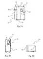
さて図面を見ると、本発明の実施の形態では、積層造形部品(AM部品)19から不要な支持材料13を除去し、同時にAM部品のビルド材16の表面仕上げを滑らかにするために、浮遊固形媒質流体(SSM流体)7が用いられている。SSM流体7は、液状媒質であり、該液状媒質内に小さな固体粒子が浮遊しているもの、および/または該液状媒質によって小さな固体粒子が運ばれるものである。粒子は、支持材料除去のための研磨および/またはAM部品表面の平滑化を促進すべく選択、含有されるものとできる。本発明は、AM部品19に付属または付着した支持材料13を除去し、同時にAM部品19の表面仕上げを滑らかにするための方法および/または装置10として実施可能である。本発明の実施の形態では、支持材料13の除去および/またはビルド材16の表面平滑化が必要なAM部品19は、装置10のスプレーチャンバ(spraying chamber)25内にあるターンテーブル22などのプラットフォーム上に設置されるものとできる。支持材料13を溶解および/または浸食させると共にAM部品19のビルド材16の表面を平滑化させるSSM流体7は、AM部品19の上方および/またはAM部品19の側方に配置されたノズル28を介してAM部品19へと噴霧(sprayed)されるものとできる。SSM流体7は、たらいのように上側34が開口したタンク31から供給されるものとできる。タンク31は、ターンテーブル22の下方に配置されるものとできる。媒質ポンプ37は、タンク31からSSM流体7を吸い出し、次にパイプ、チューブ、および/またはホースなどの流体導管43Aを介してノズル28へとSSM流体7を強制的に送るために用いられ、これが強制空気と共に、AM部品19に対するノズル28からのSSM流体7の噴霧(spray)を生じさせる。その後SSM流体7が元のタンク31へ集まると、SSM流体7はリサイクル可能となり、すなわちタンク31から吸い出され、ノズル28へとポンプで送り出され、再度AM部品19に対して噴霧される。この動作モードでは、実質的な閉ループシステムが作られるが、例外として、新鮮な強制空気(すなわち「圧縮空気」)が動作中のシステムへと追加され、タンク31内で望ましいSSM流体7の水準を維持するためにSSM流体7が定期的に追加または除去されるものとできる。 Turning now to the drawings, in an embodiment of the present invention, a floating material is used to remove
AM部品19は、さまざまな方法およびさまざまな種類の材料(例えば重合体vs金属)を用いて製造可能である。利用可能な種類の材料のうちで、特定のビルド材16(例えば重合体カテゴリ内ではナイロン、または金属カテゴリ内ではアルミニウム)および特定の支持材料(support materials)13が使用可能である。各種の積層造形法、ビルド材16および支持材料13は特有のユニークな特性および特徴を有し得るものであって、効果的かつ効率的な支持材料13の除去およびビルド材16の表面平滑化のためにさまざまなパラメータを必要とし得る。さらにAM部品19は、他のものよりもっとデリケートな特徴を有するデザインを含む、さまざまな形状を有し得るものであって、効果的かつ効率的な支持材料13の除去および/またはビルド材16の表面平滑化のために、さらなるパラメータ調節を必要とし得る。本開示の発明に関してここで詳述されるように、噴霧されるSSM流体7の量、噴霧方向(例えば上方から、および/または側方から)、SSM流体7がノズル28へとポンプで送り出される圧力、ノズル28でSSM流体7へと注入される強制空気(あれば)の量、およびSSM流体7の固形媒質粒子の種類、密度、および濃度を含むSSM流体7の組成、温度およびpHなどの任意の他のパラメータはすべて、これらのパラメータのさまざまな組み合わせ、すなわち「レシピ」を作り出すべく、カスタマイズされるものとできる。よって各「レシピ」は、所与のタイプおよびデザインのAM部品19に関して、効率的かつ効果的な所与のタイプの支持材料13の除去、および所与のタイプのビルド材16の表面平滑化にとりわけ適している。本発明では、ヒューマン・マシン・インターフェース(HMI)40を介してオペレータがこれらのパラメータを設定、記録、変更するものとでき、これは以下でさらに述べるように、モニタ40Aおよび汎用コンピュータ40Bを含むものとできる。モニタ40Aはタッチスクリーンモニタとすることができる。コンピュータ40Bによって制御される装置10のこれらの構成要素へと制御信号を送るために、有線または無線通信リンク40Cが用いられるものとできる。通信リンク40Cは、コンピュータ40Bによって制御される装置10のこれらの構成要素へと制御信号を送るために用いられる有線または無線通信リンクとして具現化可能である。有線通信リンクは、ユニバーサル・シリアル・バス(USB)、バイヨネット・ニール・コンセルマン(BNC)、光ファイバ、標準同軸、イーサネット、IEEE1394(ファイヤーワイヤー)、サンダーボルト、RS-232、DB-25、DC-37、DD-50などの有線通信プロトコルおよびデザインの器具、または他の有線通信プロトコルまたはデザインを含むものとできる。無線通信リンクは、広域ネットワーク(WAN)、IEEE802.11(ワイ・ファイ)、ブルートゥース、セルラー方式(CDMA、GSMなど)、近距離無線通信(NFC)、超短波(VHF)、極超短波(UHF)、センチメートル波(SHF)などの無線通信プロトコルおよびデザインの器具、または他の無線通信プロトコルまたはデザインを含むものとできる。
本発明は、AM部品19から支持材料13を除去し、AM部品19の外表面を平滑化するためにSSM流体7を用いる。SSM流体7は、液状媒質(水、油、溶剤、などを含むものとできる)と、液状媒質によって運ばれる、あるいはその中に浮遊する小さな固体粒子からなるものとできる。SSM流体7で利用可能な小さな固体粒子の例には、セラミックおよび金属粒子が含まれるが、これに限定されるものではない。金属粒子はいかなるタイプの金属または合金であってもよく、ステンレス鋼およびチタンを含むが、これに限定されるものではない。固体粒子を構成する材料の密度はさまざまであり得る。例えば限定の意図はないが、ある種の材料は低密度、中密度、あるいは高密度であってよく、例えば70~130ポンド/立方フィートである。液状媒質は、水、ポストプロセス・テクノロジーズ社製PolyGone(商標)などの支持材料溶剤、および泡立ち防止剤からなる清浄液とすることができる。 The present invention uses SSM fluid 7 to remove
液体中の固体粒子の浮遊状態の均一性が、該装置または方法で用いられるSSM流体7の質の指標となり得る。固体粒子がより均一に浮遊しているほど、質も高いと言える。さらにSSM流体が用いられるとき、固体粒子が均一に浮遊し続けている程度および固体粒子が浮遊状態から脱落する程度が、SSM流体の質の指標となり得る。液状媒質中の固体粒子の望ましい濃度と関連して、固体粒子の浮遊状態または濃度の均一性の一方または両方が減少するにつれSSM流体7のパフォーマンス(例えば効果および効率)が低下するものと予想される。 The uniformity of suspension of solid particles in the liquid can be an indicator of the quality of the SSM fluid 7 used in the device or method. The more uniformly the solid particles are suspended, the higher the quality. Furthermore, when an SSM fluid is used, the extent to which the solid particles remain uniformly suspended and the extent to which the solid particles fall out of suspension can be indicative of the quality of the SSM fluid. In conjunction with the desired concentration of solid particles in the liquid medium, it is expected that the performance (e.g., effectiveness and efficiency) of the SSM fluid 7 will decrease as either or both the solid particle suspension or concentration uniformity decreases. be.
本発明は、ハウジング46、電気系49、機械系52、ポンプ系55、およびスプレーチャンバ25を含むものとできる。電気系49は、装置10のさまざまなポンプ、アクチュエータ、およびセンサに動力を与え、制御する電気部品を含むものとできる。電気系49はまたHMI40を含むものとでき、これはオペレータがさまざまなパラメータを設定し装置10を操作できるように、汎用コンピュータ40Bに接続されたモニタ40Aを含むものとできる。モニタ40Aは、モニタを直接押圧することでオペレータがさまざまな動作パラメータを選択および入力可能なように、タッチスクリーン能力を備えるものとできる。機械系52は、スプレーチャンバ25内でそれぞれノズル28を動作させターンテーブル22を回転させる機械的アクチュエータ58、64を含むものとできる。機械系52はさらに、電子機器冷却用のファン61と、スプレーチャンバ25内で起きている処理に関する特定のパラメータ(すなわち温度、圧力、pHなど)を検知可能なセンサを含むものとできる。 The present invention may include
AM部品19は、不要な支持材料13を除去し、ビルド材16の表面を平滑化するためにスプレーチャンバ25内で処理される。スプレーチャンバ25内には、スプレーチャンバ25の底に配置されたタンク31、アクチュエータ64へ機械的に接続されたターンテーブル22、アクチュエータ58へ機械的に接続され、媒質ポンプ37へ流体的に接続された第1のノズル28A、アクチュエータ58へ機械的に接続され、媒質ポンプ37へ流体的に接続された第2のノズル28B、動作中にAM部品19、堆積物、および支持材料のデブリがタンク31内へ落下するのを防ぐ1つ以上の格子67、および定置洗浄(CIP)ノズル70があるものとできる。
タンク31は、ターンテーブル22の下に配置され、処理で用いられるSSM流体7の大半を保持可能である。媒質ポンプ37はタンク31の流出口73へ接続され、タンク31からSSM流体7を吸い出し、処理中のAM部品19への噴霧のためにSSM流体7をノズル28へ強制的に送るために用いられるものとできる。タンク31は、SSM流体7中の固形媒質粒子を浮遊状態に保つことに役立ちつつ、媒質ポンプ37へとつながる流出口73へのSSM流体7の流れを促進するような形状とすることができる。タンク31は、1つ以上の傾斜側面を有し、ターンテーブル22から離れて下方へと向かう浮遊粒子の流れを促進する飼い葉桶(trough)形タンク31を作り、タンク31の床部に固形媒質がたまることを防ぐ(これにより液体内での固形媒質粒子の濃縮を防ぐ)ものとできる。 A
本発明の装置10の実施の形態は、ポート79を含み、ポート79Aを介して水、ポート79Bを介して支持材料溶剤、ポート79Cを介して泡立ち防止剤、をそれぞれ供給するものとできる。装置10はまた、圧縮空気を供給するためのポート79Dを含むものとでき、これはノズル28を作動させるため、および/または固形媒質粒子をタンク31内のSSM流体7中で浮遊状態に保つために用いられるものとできる。水は施設の給水設備から、あるいはリザーバまたは他の貯蔵容器から供給されるものとできる。水が圧力下で供給される場合、タンク31への水流を自動的に制御すべくバルブが用いられるものとできる。例えば貯蔵容器からのように水が圧力下で供給されない場合、タンク31へ自動的に水を与えるべくポンプまたは投与機構(dosing mechanism)が用いられるものとできる。溶剤および泡立ち防止剤は、自らのリザーバまたは貯蔵容器またはタンク、例えばホースや他の管路によって装置10に接続された5ガロンバケツからそれぞれ供給されるものとできる。溶剤および泡立ち防止剤それぞれのためのホースは、タンク31へこれらの流体を自動的に与えるために投与機構82へと接続されるものとでき、このような投与機構82は電動ポンプまたは水力駆動ポンプとできる。このようなポンプは「ドサトロン」の商標で販売されているもののうちに見いだすことができる。 An embodiment of the
固形媒質は手作業で(例えばタンク31へ)与えられてもよいし、望ましいサイズの固体粒子を扱うのにそれが適していればだが、あらかじめ供給液体の1つに混ぜてあって、投与機構82を作動させることでSSM流体7へと与えられてもよいし、あるいは両方であってもよい。オペレータは、HMI40を用いて投与機構82を作動させ、タンク31へと望ましい量の溶剤および/または泡立ち防止剤を供給することができる。SSM流体7は、所定または別の方法で分かっている濃度(体積で)の固形媒質粒子を有するものとでき、これは部分的には固形媒質粒子の密度次第であり、高密度粒子の場合、低密度の粒子が用いられる場合と比べてより少ない体積の粒子が用いられるものとできる。HMIを用いることでオペレータは、例えば固形媒質材料の密度(例えばポンド/立方フィートの単位で)を入力することで望ましい濃度の固形媒質粒子を投入可能である。あるいはHMI40が、望ましい媒質密度に関するオペレータの理解に基づいて、オペレータに「低」、「中」、「高」などの一般的な濃度指標を選択させるものであってもよい。 The solid medium may be provided manually (e.g., to tank 31), or if it is suitable for handling solid particles of the desired size, premixed with one of the supply liquids and fed to the dosing mechanism. It may be applied to the SSM fluid 7 by actuating 82, or both. An operator can use
タンク31は液体水準センサ85を含むものとでき、こうしたセンサはSSM流体7の量が望ましい水準(HMI40を用いて設定可能)以下に低下したことを知らせるために使用可能で、これによりHMI40がSSM流体7の量を増やすようにオペレータに警告するものとできる。固形媒質の量を増やす方法の1つは、手作業または装置10を作動させもっと多くタンク31に与えることで、単純により多くの固形媒質を与えることである。水、溶剤、および泡立ち防止剤の比率はあらかじめ決められていてもよいし、オペレータが好きなように変えてもよい。
媒質ポンプ37の速度は、媒質ポンプ37から出てくるSSM流体7の流れを望ましいさまざまなレベルとできるように、調節可能なものとできる。オペレータはHMI40を用いて媒質ポンプ37の速度を調節するものとできる。媒質ポンプ37の速度は例えば、ポンプ37の最大速度の任意のパーセントとして設定される。媒質ポンプ37の速度を決定するに当たり、オペレータまたは装置10はとりわけ、SSM流体7内の固体粒子の濃度および/または密度を考慮するものとでき、粒子をしっかり浮遊状態に維持するには、粒子が高密度または高濃度であるほど媒質ポンプ37も高速であることが求められるであろうと思われる。 The speed of media pump 37 may be adjustable to allow for various levels of desired flow of SSM fluid 7 exiting
マニホルドが、媒質ポンプ37とノズル28の間に(流体的に)配置されるものとできる。このようなマニホルドは、媒質ポンプ37から流出したものがノズル28のそれぞれへの流れとなるように配分されることを可能とする。各ノズルはマニホルドの流出口へと流体導管43によって接続されるものとできる。さらに調節弁とすることが可能なバルブ88を、マニホルドと各ノズル28の間に配置することができる。このようなバルブ88は、所定時間中にノズル28へ向かって流れ、ノズル28を通過するSSM流体7の量を制御するために用いることができる。例えばバルブ88の1つは単純な開閉式であり、SSM流体7を全開で流すか、あるいはまったく流さないものとできる。あるいはバルブ88の1つは、調節可能な場合、全開位置と完全閉鎖位置の間のバルブ位置の結果として得られるSSM流体7の流量、例えば40ガロン/分またはその上下の度合い、を達成すべく調節されるものとできる。オペレータは、バルブ88の開閉および/またはバルブ88の調節によって、HMI40を用いた流量の上げ下げを達成することができる。バルブ88が完全開放されると、SSM流体7は比較的自由にバルブ88を通って流れる。バルブ88が閉鎖側へ調節されSSM流体7の流量が絞られると、固形媒質粒子が浮遊状態から脱落し、バルブ88の上流側で集まりやすくなる。流量が小さいほどこのような状態となりやすい。次にバルブ88が開放側へ調節されると、集まっていた粒子が流動する液体に取り込まれ始め、これによりSSM流体7中の固形媒質粒子の濃度が高まる。よって、バルブ88が完全開放未満に調節された状態で装置10が動作しているときにSSM流体7の量がタンク31内で望ましい水準以下に落ちたことを液体水準センサ85が知らせたならば、システム中の現在のSSM流体7へとさらなる流体を与えることに加え、あるいはそれの代わりとして、バルブ88を開放側へ調節することによってノズル28を通って流れるSSM流体7の量を増大させるものとできる。媒質ポンプ37を通って流れるSSM流体7の流速を増加させるために、媒質ポンプ37の吸入口またはタンク31の流出口73にレジューサ(reducer)が設置されてもよい。 A manifold may be (fluidically) positioned between the
ヒータ91がタンク31内または近傍に配置されるものとでき、例えばタンク31の内底部近くに設置された水中ヒータとできる。ヒータ91はSSM流体7を加熱し、作動中にSSM流体7を望ましい温度に維持するために用いられるものとできる。望ましい温度はあらかじめ定められていてもよいし、オペレータによって調節されてもよい。装置10は、温度検知用の温度センサ109を含むものとでき、またSSM流体7を望ましい温度に維持するようにヒータ91を自動的に調節するための制御装置を含むものとできる。タンク31内のSSM流体7は、処理を開始してAM部品19に対して噴霧を行う前に望ましい温度まで加熱されるものとできるが、SSM流体7は、加熱前あるいは部分的に加熱された状態で噴霧され始めるものであってもよい。後者のアプローチでは、処理は低温で始まるものとでき、処理中に時間が経過するにしたがい望ましい温度まで温度が上昇する。SSM流体7の温度を徐々に上昇させるアプローチは、支持材料13の除去に役立ち得る。これはSSM流体7が通常、任意の温度範囲にわたって支持材料13を除去可能であるためである。よってSSM流体7の加熱中にSSM流体7をAM部品19へ与えることで、SSM流体7が支持材料13の除去に好適な最低温度に到達したときにSSM流体7が支持材料13を除去(かつ露出したビルド材16を平滑化)し始め、SSM流体7が最終的に望ましい温度に近づくにつれより迅速に支持材料13を除去(かつ露出したビルド材16を平滑化)するようになる。このやり方では、処理開始時からSSM流体7が最高温度にある状況と比べて、部品のビルド材16がそれほど熱くなることがない。ビルド材16が熱に弱い場合、これはAM部品19の本体を劣化から守るのに役立つものとなり得る。 A
第1および第2のノズル28はチャンバ25内に設置され、ターンテーブル22に向けられるものとできる。ターンテーブル22は処理される1つ以上のAM部品19を支持するためのものとできる。第1のノズル28A(側方ノズル)は、垂直方向に(すなわち上下に)駆動するものとでき、その水平位置がターンテーブル22により近い位置またはより遠い位置に設定可能に配置されるものとできる。第1のノズル28Aはターンテーブル22の表面とほぼ平行にSSM流体7の噴霧を行い、よってターンテーブル22上に載置されたAM部品19の側方表面に影響を与えるものとできる。第2のノズル28B(上方ノズル)は、水平方向に(すなわち左右および/または前後に)駆動するものとでき、その垂直位置がターンテーブル22により近い位置またはより遠い位置に設定可能に配置されるものとできる。第2のノズル28Bはターンテーブル22の表面に向けて下向きにSSM流体7の噴霧を行い、よってターンテーブル22上に載置されたAM部品19の上向き表面ならびに垂直方向に向けられた表面に影響を与えるものとできる。2つ以上の第1のノズル28Aおよび/または2つ以上の第2のノズル28Bを用いてもよい。 First and
ノズル28は手作業による調節でターンテーブル22により近い位置またはより遠い位置にセットされてもよいが、ノズル28の距離を調節するこうした能力もまた自動化可能である。第1および第2のノズル28がそれぞれ上下と左右(または前後)に動く程度、ならびに動く速度は、HMI40を用いたオペレータによって設定されるものとできる。これらの距離および速度は、それぞれ装置10によって許容される任意の範囲の移動および速度内とできる。例えば第1のノズル28Aは、最大43ミリメートルで任意の距離だけ上下に移動できるように設定され、始点はターンテーブル22の上面から6ミリメートル上方とすることができる。第2のノズル28Bは、最大112ミリメートルで任意の距離だけ前後に移動できるように設定され、この移動の中心点はターンテーブル22の中心と揃うものとすることができる。同様に、例えば第1のノズル28Aは、速度22ミリメートル/秒で移動するものとして設定され、第2のノズル28Bは、同じ速度または異なる速度で移動するものとして設定されるものとできる。 Although the
図面に描かれた実施の形態は、1つの側方ノズルと1つの上方ノズルを有するものだが、複数の側方および/または上方ノズル28が用いられるものであってもよい。さらに、図面に描かれた実施の形態は、向きが固定されたノズル28を示しているが、機構および制御装置を組み込んで、ノズル28が接続先のアクチュエータ58から独立したさらに大きな可動範囲を有するものとしてもよい。例えば側方ノズル28Aは、上下移動に加えて、独自の軸を中心に左右、上下、および/または回転運動で関節動作を行う構成とされてもよい。同様に、上方ノズル28Bが独自の軸を中心に左右、前後、および/または回転運動で関節動作を行う構成とされてもよい。ノズル28が関節動作する速度もまた調節可能とできる。 Although the illustrated embodiment has one side nozzle and one top nozzle, multiple side and/or
図5および6を参照すると、ノズル28は(媒質ポンプ37からの)SSM流体7用の流入口、および(ポンプ104またはポート79Dからの)圧縮空気用の流入口を備えるものとしてデザインされることができる。より詳しく言えば、こうしたノズル28は、それぞれSSM流体7と圧縮空気の供給源が接続されている流入口105、103を有するマニホルド95に取り付けられるものとできる。SSM流体7は圧縮空気の上流で、マニホルド95を介してノズル28へ入るものとできる。インジェクタ107を用いてSSM流体7の流れへ空気ポンプ104またはポート79Dからの圧縮空気を加えることができる。空気がSSM流体7へと注入される場所は、マニホルド95であってもよいしノズル28であってもよい。圧縮空気の注入は、ターンテーブル22上に載置されたAM部品19へと向かうSSM流体7の高速流を作り出す。高速のSSM流体7と支持材料13の衝突が、ビルド材16と支持材料13の間の接続点を破壊する。さらにAM部品19へのSSM流体7の衝突、ならびに以後のAM部品19表面に沿っての流れが、SSM流体7中の固体粒子が研磨材となることで、ビルド材16の外表面を平滑化する。加えてさらに、SSM流体7の一部である液体溶剤が、支持材料およびAM部品19の外表面を化学的に溶解させるように調合され、表面仕上げと不要な支持材料13の除去にさらに役立つものとできる。 5 and 6,
ノズル28の形状次第で、SSM流体7がノズル28を離れる速度および圧力は、(媒質ポンプ37の速度および/またはバルブ88を調節することで)SSM流体7の体積流量を変えることで、インジェクタ107で注入される空気流の圧力を変えることで、あるいは両者を組み合わせることで、変化させられるものとできる。空気流の圧力は、圧縮空気供給源とノズル28との間に配置されたバルブ94Aを用いることで上下に調節可能である。第1および第2のノズル28A、28Bに別々のバルブ94Aを用いれば、各ノズル28での空気圧は、同一にも異なる水準にも設定可能である。ノズル28への空気供給にバルブ94Aを用いることに加え、バルブ94Aは各ノズル28への空気供給を選択的にオンまたはオフに切り替えるために用いられてもよい。これは選択された間隔でノズル28への空気をオンオフ切り替えすることによる「律動(pulsing)」を含むものとでき、これによりノズルを離れるSSM7流体の速度および圧力を律動的なものとできる。例えば空気供給バルブ94Aは5秒ごとにオンとされ、オンとなるごとに1秒間稼働するものとして設定される。空気バルブ94Aの開閉の頻度および持続時間は装置10によって許容される任意の値の範囲内とされ、HMI40を用いてオペレータによって設定されるものとできる。SSM流体7の流れを変えるこの能力は、処理全体の効率および有効性を高め、さらには処理中に部品がダメージを受ける恐れを減らすことができる。チャンバ25はベント97を含み、ノズル28を介して空気が注入される際に、チャンバ25内の余分な空気が過剰または危険なレベルまで蓄積される代わりに、ベント97を通って逃げるものとできる。 Depending on the geometry of
さらに、AM部品からの支持材料13の除去および/またはAM部品の表面の平滑化にすべてのノズル28が必要ではない場合、および/または、いくつかのノズル28を他のものより高圧または低圧とすること、および/または律動的に作動させることが望ましい場合には、ノズル28が選択的に使用される、および/または、効率および/または有効性を高めるべくノズル28が調節されるものとできる。こうした汎用性を可能とするために、媒質ポンプ37からの(マニホルドそしてノズル28へと達する)流れのレベルは、その流れの最大レベルの任意のパーセンテージ(例えば65%)として設定され、および/または、強制給気からの(ノズル28へと達する)空気の圧力は、その最大圧力の任意のパーセンテージ(例えば40%)として設定されるものとできる。これらは「システムレベル設定(system level settings)」と称される。また、(a)各ノズル28へのSSM流体7の流れを制御するバルブ88が開閉され、開放時に開度(例えば完全開放状態の任意のパーセンテージとして)が変更されるものとでき、および/または、(b)個々のノズル28それぞれへの給気が(各ノズル28への給気に接続されたバルブ94Aの開閉によって)完全に、または望ましい律動レベルを生むための選択された頻度および持続時間(例えば5秒ごとに1秒間開放)で、オンオフされるものとできる。これらは「ノズルレベル設定(nozzle level settings)」と称される。 Additionally, if not all
例えばある動作モードでは、側方ノズル28Aから流れてくるSSM流体7の圧力が低レベル(例えば流体が75%、空気が20%)に設定されて、上方ノズル28Bから流れてくるSSM流体7の圧力もまた低レベルに設定されるか、あるいは上方ノズル28Bへのバルブ88が閉じられて側方ノズル28AのみからSSM流体7が噴霧される。これはシステムレベル設定のみ、またはシステムおよびノズルレベル設定の組み合わせにより達成可能である。このモードはチャンバ25内で処理中の積層造形部品に低水準のアジテーションを生じるもので、「超低アジテーション」と称される。他の動作モードでは、側方ノズル28Aおよび上方ノズル28Bから流れてくるSSM流体7の圧力が、超低アジテーションよりもわずかに高いレベル(例えば流体が75%、空気が30%)に設定され、上方ノズル28Bが短時間、間欠的に動作する(すなわち律動する)(例えば1秒おきに1秒間開放)。SSM流体7および空気の圧力は、システムレベル設定のみ、またはシステムおよびノズルレベル設定の組み合わせにより達成可能であり、律動は、少なくとも空気用にノズルレベル設定の使用を必要とする。このモードは「超低アジテーション」よりもアジテーションの度合を高めるもので、「低アジテーション」と称される。さらに他の動作モードでは、側方および上方ノズル28A、28Bの双方へと流れるSSM流体7の圧力が中レベル(例えば流体が100%、空気が50%)に設定されるが、その後、間欠的に上方調節され、(空気設定を例えば70%へと増加することにより)ノズル28A、28Bの双方で律動式に圧力が高められる。このモードは「低アジテーション」の設定よりもアジテーションの度合を高めるもので、「中アジテーション」と称される。さらに他の動作モードでは、側方および上方ノズル28A、28Bの双方へと流れるSSM流体7の圧力が高レベル(例えば流体が100%、空気が70%以上)に設定される。このモードは高レベルのアジテーションを生じるもので、「高アジテーション」と称される。ノズル28の他の配置、バルブ88、94Aの開と閉、および高低さまざまな流体圧および空気圧の組み合わせ、および/または低圧高圧の間欠的使用によって、アジテーションレベルにさまざまな変化をもたらすことが可能である。よって「低」、「中」、「高」の用語の使用は、これまでの例で述べた具体的な配置に限定されることを意図するものではなく、むしろ程度がさまざまで相対的なアジテーションを、具体的な要求に応えるべく、好きなように達成し得ることを例示するためのものである。 For example, in one mode of operation, the pressure of the SSM fluid 7 flowing from the
HMI40は、オペレータが、総合的に所望のレベルのアジテーションを達成する動作パラメータを設定できるものとして、あるいはHMIで示されるオプションから所望のレベルのアジテーションを選択できるものとして、あるいは、アジテーションレベルが、オペレータが選択オプションまたは規定オプションを有する所与の動作レシピと関連して事前格納されるものとして、構成されるものとできる。アジテーションレベルの設定により、装置10は自動的にノズル28へのバルブ88を開閉して圧力を調節し、該レベルのアジテーションを達成することができる。 The
装置10にはさらに、SSM流体7用のpHセンサ106、温度センサ109、および/または圧力センサ112が含まれるものとできる。温度センサ109は、タンク31内のSSM流体7の温度を検知するものとできる。pHセンサ106は、タンク31内のSSM流体7のpH値を検知するものとできる。圧力センサ112は、バルブ88またはノズル28の圧力の変化または圧力がないことを検知するために用いられるものとできる。圧力変化は、除去が必要な障害物があることを示し得る。
カメラ115などからなる視覚システムが、支持材料13の除去速度またはビルド材16の表面仕上げの発生速度を検知するために含まれるものとできる。視覚システムはまた、任意の時点での表面仕上げの滑らかさのレベルを検知するものとできる。視覚システムによって読み込まれたイメージはまた、支持材料13を含むAM部品19のCADファイルと比較され、進行中の処理を最適化するものとできる。この比較は、HMI40と関連付けられたコンピュータ40B、または、いつ所望量の支持材料13がAM部品19から除去されたかを検知するための、および/または、いつビルド材16の特定の表面仕上げが達成されたかを検知するための別のコンピュータによって行われるものとできる。 A vision system, such as
ターンテーブル22は、ノズル28から噴霧されるSSM流体7がターンテーブル22を通過してタンク31へ入れるように、かつターンテーブル22表面の上面に集まることがないように開口を有するものとできる。ターンテーブル22は、処理される1つ以上のAM部品19が好適な手段、例えばTナット、ボルト、クランプなどを用いてターンテーブル22へと固定可能な特徴を含むものとできる。 The
あるいはターンテーブル22にケージ構造物が設置され、AM部品19が処理中に転倒してもケージによって規制されるものとできる。ターンテーブル22は、ターンテーブル22を時計方向または反時計方向に回転させるためのアクチュエータ64へ接続されるものとできる。アクチュエータ64は、例えばギアを有するシャフトを回転させるサーボモータであって、該ギアならびにターンテーブル22に接続されたギアにチェーンが取り付けられ、これによりターンテーブル22を回転させる。回転速度は変更可能であって、HMI40を用いるオペレータによって設定されるものとできる。ターンテーブル22が回転する速度は、装置10によって許容される任意の速度とでき、例えばターンテーブル22が回転する最大RPM(回転数/分)のパーセンテージとして表現可能である。1つ以上の格子67がターンテーブル22の近傍または下に配置され、支持材料13または他の不要な堆積物がタンク31内へ落下するのを防ぐ。装置10はターンテーブル22近傍に配置された上側格子67Aを含むものとできる。また、ターンテーブル22の下でタンク31により近い位置に下側格子67Bが設けられ、上側格子67A(複数可)あるいはターンテーブル22の開口を通って落下する不要な支持材料13の破片または他のデブリや堆積物を捕まえ、こうした破片、デブリ、および/または堆積物が媒質ポンプ37へ吸い込まれることを防ぐものとできる。あるいは上側格子67A(複数可)が省略されて下側格子67B(複数可)のみが用いられるものであってもよいし、その逆でもよい。 Alternatively, a cage structure may be installed on the
ポンプ系55は、媒質ポンプ37とCIPポンプ118を含むものとできる。媒質ポンプ37は、タンク31の流出口73と流体連結された流入口を有し、このようなタンク流出口73は、SSM流体7が蓄えられているタンク31の底部またはその近傍にある。媒質ポンプ31の出口は、マニホルドとして配置される流体導管43Aへと接続され、マニホルドの流出口は、スプレーチャンバ25内に配置されたノズル28へ流体接続されるものとできる。調節弁とすることが可能なバルブ88は、マニホルドとノズル28の間にインラインで設置され、流れをオンオフするために、あるいはノズル28へのSSM流体7の流量を調節するために用いられるものとできる。媒質ポンプ37の速度もまた、マニホルドおよびノズル28へのSSM流体7の流量を増減するように調節されるものとできる。
媒質ポンプ37は、好ましくは(体積で)最大50%の固体粒子濃度のSSM流体7を含むSSM流体7を扱うのに好適である。このような高い固体濃度を扱える媒質ポンプ37の能力のお陰で、SSM流体7は高圧かつ高速で流れることができる。SSM流体7がノズル28から押し出されてAM部品に噴霧された後、SSM流体7はタンク31へと再び集められ、タンク31が再びSSM流体7を媒質ポンプ37へと供給し、次に媒質ポンプ37が再びSSM流体7をノズル28へと送り出す。 The media pump 37 is suitable for handling SSM fluids 7, preferably including SSM fluids 7 with a solid particle concentration of up to 50% (by volume). The ability of the media pump 37 to handle such high solids concentrations allows the SSM fluid 7 to flow at high pressures and velocities. After the SSM fluid 7 is forced out of the
タンク31は、SSM流体7がタンク流出口73、次いで媒質ポンプ37へと流れることを助長するようにデザインされているものとできる。固体粒子は溶液から脱落してタンク31の床に集まり得る。タンク31は、タンク31の床にこうした粒子が集まることを防ぐ渦などの流れのパターンを作り出す形状とされるものとできる。タンク31の床に粒子が集まることを防ぐ他の方法は、媒質ポンプ37をノズル28だけでなく、(直接またはマニホルドを介して)タンク31へと戻るように接続された1つ以上の流体導管43B(例えばホース、チューブ、および/またはパイプ)へも接続することで、媒質ポンプ37を利用することである。バルブ100は、媒質ポンプ37と流体導管43Bの間、さもなくば流体導管43Bとインラインで設置されるものとできる。これにより媒質ポンプ37によってタンク31から吸い出されたSSM流体7の一部は、SSM流体7の十分な混合状態を維持するため、およびタンク31の床に粒子が集まることを防止するため、タンク31へと直接還流されるものとできる。さらに強制給気からの圧縮空気が、SSM流体7の十分な混合状態を維持するため、およびタンク31の床に粒子が集まることを防止するため、タンク31内のSSM流体7へと与えられるものとできる。タンク31内のSSM流体7へと与えられるこのような空気の量は、バルブ94Bを用いて調節され、HMI40を用いて制御されるものとできる。タンク31への直接的なSSM流体7と圧縮空気の同時供給は、SSM流体7内の媒質粒子の浮遊状態を維持するのに役立つようにタンク31内に流れまたはアジテーションを生じる。この流れ/アジテーションは、処理動作中に連続的に、または間欠的に、さまざまなレベルの圧力で発生させられるものとできる。例えばSSM流体7で高密度および/または高濃度の固形媒質が用いられている場合、流れ/アジテーションは、より高頻度および高圧力下のものとでき、例えば30秒ごとにオンオフされ、強制空気は圧力が20psiである。上述のごとく、媒質ポンプ37の速度は調節可能なものとでき、よって媒質ポンプ37の速度の設定において、オペレータまたはコンピュータ40Bが、SSM流体7内の固体粒子の濃度および/または密度に責任を負うものとできる(高密度または高濃度の粒子は、粒子を浮遊状態に保つために媒質ポンプ37がより高速であることを必要とする)。固形媒質の密度が低い場合、タンク31へと戻るSSM流体7および/または空気の流れは、より低頻度および低圧力下のものとでき、例えば2分ごとにオンオフされ、強制空気は圧力が10psiである。これらのパラメータは、固体粒子を浮遊状態に保つために必要に応じて設定されるものとできる。これらのパラメータは、コンピュータ40Bにあらかじめプログラムされたものでも、HMI40を用いてオペレータによって手作業で選択されるものであってもよい。固形媒質の浮遊状態を維持するためにこのようなアプローチを採用することで、タンク31へ傾斜側面73を組み込むことの重要性は低下するが、一方または両方が採用されてもよい。
あるAM部品19または組となったAM部品19を処理するにあたり、オペレータがHMI40を用いて実行時間の長さを設定するものであってもよく、あるいは実行時間が概ね、あるいは所与のレシピに関して、あらかじめ決定されていてもよい。本発明に基づくシステムの動作中、SSM流体7からの固体粒子は、チャンバ25の表面およびチャンバ25内の構造体(ノズル28、ターンテーブル22などを含む)上に集まり、処理が終わりに近づくにつれ処理中のAM部品19の表面にも集まったりする。装置10は、これらの表面から固体粒子を洗い流すためのCIPシステム121を含むものとできる。CIPシステム121は、直接またはマニホルドを介してCIPノズル70へと接続されたCIP118ポンプを有し、この洗浄処理に固形媒質を含まない液体溶剤またはただの水を用いるものとできる。この洗浄目的の液体溶剤は、SSM流体7から抽出されるものとできる。より具体的には、SSM流体7の噴霧処理が終わった後、タンク31のSSM流体7中に浮遊する媒質粒子がタンク31の底へ沈殿するのに十分な時間だけ媒質ポンプ37がオフされるものとできる。CIPポンプ118へのCIP流入口124は、タンク31へ接続され、かつタンク31内のCIP流入口124の開口がタンク31の底から十分な高さとなるように配置されるものとでき、CIPポンプ118へと入るSSM流体7から固形媒質粒子が(それらがタンク31の底へ沈殿してしまうことで)なくなる、あるいは実質的になくなるものとできる。CIPポンプ118およびCIPノズル70に入ろうとする固体粒子を減らす、またはなくすために、フィルタ127がCIP流入口124と組み合わされてもよい。CIPポンプ118は所定時間動作され、タンク31から流体を吸い出してノズル28へ強制的に送るものとでき、そこで流体がチャンバ25内の表面に対して噴霧され、該表面から固形媒質粒子をタンク31内へと洗い流す。あるいは、このような洗浄目的で清浄な水または清浄な溶剤が供給されてもよい。CIPノズル70は好適な任意のノズルとでき、また限定されるものではないが、複数の穴を備えた1本のチューブ、あるいは複数のチューブと複数の穴(または該複数のチューブ上に配置された複数のノズル)からなるシステムからなるものとできる。 In processing an
たらい1つのみのタンク31を用いる代わりに、タンク31が2つの領域:SSM流体7を収容する第1の領域、清浄な液体溶剤または水のみを収容する第2の領域、に分割されていてもよい。清浄な液体溶剤/水を収容する領域は、CIPシステム121用に用いられるものであり、清浄な液体溶剤/水を望ましい温度に保つための専用のヒータを含むものとできる。さらにCIPポンプ118は、タンク31から液体溶剤/水をすべて汲み出すために用いられてもよい。 Instead of using a
本発明は、積層造形部品の支持材料を除去、および/または、積層造形部品の表面を平滑化する方法として実施可能である。この方法では、スプレーチャンバ、支持表面、1つ以上のノズル、AM部品、SSM流体が準備(200)されるものとできる。AM部品は支持表面上に配置され(203)、ノズルからAM部品へとSSM流体が噴霧(206)されるものとできる。 The present invention can be implemented as a method of removing support material from an additively manufactured part and/or smoothing the surface of an additively manufactured part. The method may include providing (200) a spray chamber, a support surface, one or more nozzles, an AM component, and an SSM fluid. The AM component may be placed (203) on a support surface and SSM fluid may be sprayed (206) from a nozzle onto the AM component.
第1のノズル28Aの水平位置および第2のノズル28Bの垂直位置は、ターンテーブル22から望ましい距離だけ離れるものとして調節されるものとできる。AM部品19は、貫通ドア130を介してアクセス可能なスプレーチャンバ25内でターンテーブル22上に配置されるものとできる。AM部品19はターンテーブル22上に載置されるものとでき、これはケージ覆いがあってもなくてもよく、あるいはターンテーブル22に固定されるものとできる。次に貫通ドア130が閉じられ、しっかりと封鎖され、スプレーチャンバ25を基本的に水密とするものとできる。ユーザは次に、HMI40の入力システムを用い、密度、形状、材料、および/または気孔率などAM部品19および/または支持材料13およびビルド材16の特性に基づいて、装置10のための動作パラメータを選択するものとできる。動作パラメータは、SSM流体7を構成する液体および固体粒子の濃度、タンク31内のSSM流体7が加熱されて到達すべき温度、維持されるべきpH値、(媒質ポンプ37の速度と、媒質ポンプ37とノズル28の間にあるバルブ88の開度の一方または両方を設定することによる)SSM流体7がノズル28へ向けてポンプで送り出される際の圧力、ノズル28へ向かう空気の圧力、各ノズル28のオンオフおよび/または律動レベル、処理実行時間の長さ、タンク31のSSM流体7内で固体粒子を浮遊状態に保つためのアジテーションレベル(すなわち、流体がタンク31へとポンプで直接送り返される間隔、およびタンク31へと供給される空気の圧力)、および/または、処理終了時の洗浄時間の長さ、のうち1つ以上が含まれるものとできる。動作パラメータはまた、好ましくはAM部品19が処理中、SSM流体7噴霧によって常に包まれた状態となるように設定されるノズル28の始点および移動距離用の設定、ならびにノズル28の移動速度およびターンテーブル22の回転方向および速度を含むものとできる。こうした距離および速度は、システムによって許容される最小値および最大値の間の任意の値とできる。こうしたパラメータは、HMI40を用いるオペレータによって選択されるさまざまな「レシピ」として装置10へとあらかじめプログラムされるものとできる。こうしたパラメータは改変され、支持体除去および表面仕上げ処理の効率を高めるために選択されるものとでき、例えばサイクル時間を短くしたり、望ましい外表面粗さを下げたりする。本発明の実施の形態では、例えば、支持材料13、ビルド材16、AM部品19の形状、表面粗さなどを含むそれらの特性を識別可能な視覚システムを用いて、パラメータのいくつかまたはすべてが、自動的に決定されるものとできる。この時、AM部品が望ましい結果に向けて処理されるようコンピュータ40Bが対処して、動作パラメータを調節するものとできる。この評価を行う際の一助となるように、視覚システムは、AM部品19のCADモデルファイルおよび他のメタデータを用いることができる。 The horizontal position of the
動作パラメータが入力または別のやり方で選択された後、タンク31が(選択された動作パラメータに基づいて完全に自動的に、あるいは、オペレータが手作業で固体粒子を加えることで)SSM流体7を構成する流体と固形媒質粒子とで満たされるものとできる。液体水準センサ85は、タンク31が望ましい水準まで満たされたことを知らせることができ、その時点で注入が停止する。タンク31内のヒータ91が作動させられ、SSM流体7を望ましい温度まで加熱し始めることができる。この時点で支持体除去および表面仕上げ処理を開始するものとできる。これはSSM流体7が所望の最終温度まで加熱される前に始まっても、された後に始まってもよい。媒質ポンプ37が作動させられ、SSM流体7をタンク31から強制的に流出させ、媒質ポンプ37を介してノズル28まで送るものとできる。媒質ポンプ37はまた、SSM流体7の一部を強制的に、所定間隔で直接タンク31に還流させるものとでき、よってタンク31へ供給される強制空気と共になって、固体粒子が浮遊状態に保たれる。第1および第2のノズル28は、AM部品19が配置されたターンテーブル22へと向けられるものとできる。SSM流体7がノズル28へ入ると、SSM流体7はノズル28内の圧縮空気流と混ざり合うことができる。このSSM流体7と圧縮空気の混合は、AM部品19に向けて噴霧されるSSM流体7の高速加圧流を生じ、支持材料13およびAM部品19のビルド材16の表面に影響を与える。 After the operating parameters have been entered or otherwise selected, tank 31 (either fully automatically based on the selected operating parameters or by manual addition of solid particles by an operator) supplies SSM fluid 7. It can be filled with constituent fluids and solid media particles. A
媒質ポンプ37がノズル28を介してSSM流体7を押し出し始めると、アクチュエータ58が、選択された動作パラメータによって指示される距離範囲および速度でノズル28を動かすものとできる。選択された動作パラメータによる指示で、ノズル28からの流れは律動することもできる。第1の(側方)ノズル28A(複数可)は垂直方向へ動作するものとでき、第2の(上方)ノズル28B(複数可)は水平方向へと動作するものとできる。さらに上にAM部品19が載置されたターンテーブル22は、選択された動作パラメータによって指示される方向および速度で円運動で回転するものとできる。ノズル28の垂直水平方向運動(その移動範囲と速度を含む)とターンテーブル22の回転(および回転速度)の組み合わせによって、ビルド材16の全外表面が平滑化され、不要な支持材料13が除去されるものとできる。この組み合わせはまた、AM部品19の特定の領域を狙うためにも使用可能である。例えば、AM部品19上で支持材料13が非対称であれば、AM部品19は、支持材料13がたくさんある側がより長時間ターゲットとなるように向けられるものとできる。さらに、ノズル28によって発生する所与の圧力および速度(ならびに律動)に関して言えば、SSM流体7がAM部品19の外表面および支持材料13に影響を与える該圧力は、ノズル28が設置されている場所のターンテーブル22からの距離、ならびにターンテーブル22が回転する速度および第1および第2のノズル28A、28Bがそれぞれ垂直方向、水平方向に作動させられる速度に応じて変わるものとできる。ちなみに、両タイプのノズル28A、28Bならびにターンテーブル22は、処理のサイクル時間を短くすると同時に処理の効率および/または有効性を高めるために、例えば表面仕上げおよび支持体除去を良くするために、同時に作動するものとできる。 As media pump 37 begins to push SSM fluid 7 through
処理のためのパラメータはさまざまであってよく、および/または、AM部品19が作られている特定のビルド材16および支持材料13、支持材料13の形状を含むAM部品19の形状、および支持材料13が除去される程度および速度、ならびにビルド材16が平滑化される程度および速度に責任を負うべくカスタマイズされてもよい。さらに、あるAM部品19または組となったAM部品19に対する一度の処理中に、動作パラメータが一定のままである必要はない。例えば、サイクルの開始時においては攻撃的に設定され、次いで自動的に調節、あるいは手作業で調節されて、支持材料13の残りが少なくなる処理後半にはより攻撃性の低い設定とされてもよい。パラメータのいくつかまたはすべてを決定するのに視覚システムが用いられる場合には、処理中のAM部品19の評価にも視覚システムが用いられ、例えば、残っている支持材料13の量、およびこれまでに達成されたビルド材16の平滑さvs望ましい最終的な平滑さの水準、を含む任意の数の要素に基づいて、動作パラメータへの変更を制御システムに知らせるものとできる。これらの動作パラメータをバランスを取りながら変えることで、支持材料13が除去されビルド材16の表面が平滑化される効果および効率を、AM部品19にダメージを与えることなく高くできる。さらに、ある目標を他の目標よりも優先させる選択が行われてもよい。例えば、所与の材料から作られた所与のAM部品19形状に関するビルド材16表面平滑化vs支持材料13除去において、流体圧を減らすこと、空気量を減らすこと、律動量を減らすこと、SSM流体7内の固形媒質比を変えること、SSM流体7の組成を変えること、またはそれらの組み合わせが好ましい場合がある。所与の動作パラメータの組み合わせがコンピュータ40Bと関連するメモリにレシピとしてセーブされ、将来、動作パラメータをそれぞれ再入力する代わりに、このレシピがオペレータによって選択されるものとできる。 The parameters for processing may vary and/or may vary depending on the
処理中、SSM流体7が(例えば流体の蒸発により)最小レベル以下に落ちたことを液体水準センサ85が知らせると、投与機構82を用いて追加の流体が自動的に供給され、望ましい濃度にしたがってタンク31を再び満たすものとできる。同様に、pHレベルが望ましいレベルでなくなったことをpHセンサ106が知らせると、投与機構82を用いて追加の流体が与えられ、pHを上方または下方へと調節するものとできる。効率のため、SSM流体7は加熱、すなわち最低温度以上に保たれるものとできる。他方で、SSM流体7が熱くなりすぎると、AM部品19にダメージを与えたり劣化させたりする。こうした場合、ユーザが温度を制御し、加熱されるSSM流体7が最大温度以上とならないことを確実なものとすることができる。 During processing, when the
SSM流体7噴霧の所望のサイクル時間が終わりに達すると、媒質ポンプ37が動作をやめ、SSM流体7中の固体粒子がタンク31の底へと沈殿することが許されるものとできる。次にCIPポンプがタンク31から(固形媒質粒子がない、あるいは実質的にない)流体を吸い出し始め、強制的にCIPノズル70を通過させ、スプレーチャンバ25の表面および内部から、ならびにAM部品19の表面から、残留固体粒子を除去するものとできる。主たるAM部品19処理サイクルと洗浄サイクルの両方で、タンク31内のSSM流体7からの熱がチャンバ25内の空気を暖めることができ、この暖気は洗浄サイクル後にAM部品19を乾かすのに役立つことができる。CIPサイクルが完了すると、オペレータはスプレーチャンバ25を開き、AM部品19を取り出すものとできる。チャンバ25からAM部品19を取り出す前に、オペレータが乾燥の時間を与えてもよく、この乾燥はチャンバ25内の熱せられた空気によって促進される。 When the desired cycle time of the SSM fluid 7 spray reaches the end, the
当然ながら、以上に開示した本発明の様々な側面、および他の特徴および機能、またはその代案を望むがままに組み合わせて、他の多くの異なるシステムまたは用途とすることが可能である。現時点では予想も予期もされていない様々な代案、変形、変異、または改良が今後当業者によってなされる可能性もあるが、そうした代案、変形、変異、および/または改良も包含されるものである。 Of course, the various aspects of the invention disclosed above, and other features and functions, or alternatives thereof, can be combined as desired into many other different systems or applications. Various alternatives, variations, variations, or improvements that are not anticipated or anticipated at this time may be made by those skilled in the art in the future, and such alternatives, variations, variations, and/or improvements are also included. .
1つ以上の特定の実施の形態に関して本発明を説明してきたが、本発明の他の実施の形態が、本発明の精神と範囲から逸脱することなくなし得ることを理解されたい。とりわけ、本発明の方法は、本明細書に記載の行為および/またはステップの組み合わせとできる。 While the invention has been described with respect to one or more specific embodiments, it should be appreciated that other embodiments of the invention may be made without departing from the spirit and scope of the invention. Among other things, methods of the invention can be a combination of acts and/or steps described herein.
Claims (25)
Translated fromJapanese前記スプレーチャンバ内にあり、積層造形部品を支持するものとして作られた支持表面、および
前記積層造形部品に浮遊固形媒質流体(SSM流体)を噴霧するものとして作られた1つ以上のノズルを含み、
前記SSM流体が固体粒子と泡立ち防止剤と液体を含む、積層造形部品のビルド材の表面を平滑化する装置。spray chamber,
a support surface within said spray chamber and configured to support an additively manufactured part; and one or more nozzles configured to spray a suspended solids media fluid (SSM fluid) onto said additively manufactured part. ,
An apparatus for smoothing the surfaceof a build material for anadditively manufactured part, wherein the SSM fluid comprises solid particles,an antifoaming agent and a liquid.
前記SSM流体の流れを受け入れる第1の流入口、
空気の流れを受け入れる第2の流入口、
SSM流体が前記ノズルの外に出ることが可能な流出口をさらに含み、
前記ノズルが、前記ノズルの前記流出口から外に出る前に前記SSM流体と前記空気を混ぜ合わせる形状とされている請求項1、2、3のいずれかに記載の装置。at least one of the one or more nozzles
a first inlet for receiving the SSM fluid flow;
a second inlet for receiving a flow of air;
further comprising an outlet through which SSM fluid can exit said nozzle;
4. Apparatus according to claim 1, 2 or 3, wherein said nozzle is shaped to mix said SSM fluid with said air prior to exiting said outlet of said nozzle.
該装置が前記支持表面を回転させるためのアクチュエータをさらに含む請求項5記載の装置。the support surface is rotatable in one or both clockwise and counterclockwise directions;
6. The device of claim 5, wherein said device further comprises an actuator for rotating said support surface.
第1の方向へと前記SSM流体を噴霧する構成とされた第1のノズル、および
第2の方向へと前記SSM流体を噴霧する構成とされた第2のノズルを含む請求項1記載の装置。the nozzle
a first nozzle configured to spray the SSM fluid in afirst direction; and
2. The apparatus of claim 1, including a second nozzle configured to spray said SSM fluid in a second direction.
前記第2の方向が垂直方向である請求項8記載の装置。the first direction ishorizontal ;
9. The apparatus of claim 8, wherein said seconddirection is vertical .
液体と固体粒子を含む浮遊固形媒質流体(SSM流体)を供給し、
前記SSM流体を、前記チャンバ内に配置され、前記積層造形部品のビルド材の表面に向けて前記SSM流体を噴霧するものとして作られたノズルから前記積層造形部品のビルド材の表面に向けて噴霧し、前記積層造形部品のビルド材の表面を研磨し、これにより前記積層造形部品のビルド材の表面を平滑化することを含む、積層造形部品のビルド材の表面を平滑化する方法。supporting the additively manufactured part on a support surface within the spray chamber and configured to support the additivelymanufactured part;
providing a suspended solids medium fluid (SSM fluid) containing liquid and solid particles;
spraying the SSM fluid onto the surface of the build material of the additively manufactured part from a nozzle disposed within the chamber and configured to spray the SSM fluid toward the surface of the build material of the additively manufactured part;and polishing the surface of the build material of the additively manufactured part, thereby smoothing the surface of the build material of the additively manufacturedpart.
前記空気流と前記SSM流体を混ぜ合わせることをさらに含む請求項20記載の方法。give airflow,
21. The method of Claim 20, further comprising mixing the airflow and the SSM fluid.
Applications Claiming Priority (3)
| Application Number | Priority Date | Filing Date | Title |
|---|---|---|---|
| US201762595030P | 2017-12-05 | 2017-12-05 | |
| US62/595,030 | 2017-12-05 | ||
| PCT/US2018/063898WO2019113104A1 (en) | 2017-12-05 | 2018-12-04 | Method and apparatus for surface finishing and support material removal (deci duo) |
Publications (2)
| Publication Number | Publication Date |
|---|---|
| JP2021505433A JP2021505433A (en) | 2021-02-18 |
| JP7247189B2true JP7247189B2 (en) | 2023-03-28 |
Family
ID=66734991
Family Applications (1)
| Application Number | Title | Priority Date | Filing Date |
|---|---|---|---|
| JP2020529747AActiveJP7247189B2 (en) | 2017-12-05 | 2018-12-04 | Method and Apparatus for Surface Finishing and Support Material Removal (DECI DUO) |
Country Status (5)
| Country | Link |
|---|---|
| US (1) | US11491724B2 (en) |
| EP (1) | EP3720688A4 (en) |
| JP (1) | JP7247189B2 (en) |
| KR (1) | KR102586367B1 (en) |
| WO (1) | WO2019113104A1 (en) |
Families Citing this family (24)
| Publication number | Priority date | Publication date | Assignee | Title |
|---|---|---|---|---|
| WO2021158812A1 (en)* | 2020-02-04 | 2021-08-12 | Postprocess Technologies, Inc. | Vision system and method for apparatus for support removal using directed atomized and semi-atomized fluid |
| US12325189B2 (en)* | 2017-12-05 | 2025-06-10 | Postprocess Technologies, Inc. | Vision system and method for apparatus for support removal using directed atomized and semi-atomized fluid |
| US11524464B2 (en) | 2017-12-31 | 2022-12-13 | Postprocess Technologies, Inc. | Method and apparatus for support removal using directed atomized and semi-atomized fluid |
| EP3731972A4 (en)* | 2017-12-31 | 2021-08-25 | PostProcess Technologies Inc. | Method and apparatus for support removal using directed atomized and semi-atomized fluid |
| US12327738B2 (en)* | 2018-05-03 | 2025-06-10 | Applied Materials, Inc. | Integrated semiconductor part cleaning system |
| WO2020006141A1 (en) | 2018-06-26 | 2020-01-02 | Postprocess Technologies, Inc. | Compositions for removing support material from a 3d-printed object and methods of making thereof |
| JP7120122B2 (en)* | 2019-03-29 | 2022-08-17 | 新東工業株式会社 | Additive manufacturing system and removal method |
| US20220143703A1 (en)* | 2019-04-30 | 2022-05-12 | Hewlett-Packard Development Company, L.P. | Material removal system |
| JP7572976B2 (en)* | 2019-06-18 | 2024-10-24 | ポストプロセス テクノロジーズ インク | Methods and compositions for modifying additively manufactured metal or metal alloy objects |
| US12194682B2 (en)* | 2019-08-06 | 2025-01-14 | Postprocess Technologies, Inc. | Method and apparatus for support removal using directed atomized and semi-atomized fluid |
| US11707772B2 (en) | 2019-10-29 | 2023-07-25 | United States Of America As Represented By The Administrator Of Nasa | High flow differential cleaning system |
| US11273607B2 (en)* | 2019-11-15 | 2022-03-15 | Arcam Ab | Depowdering apparatuses for additive manufacturing and methods for using the same |
| DE102020108761B8 (en)* | 2020-03-30 | 2022-11-17 | Actech Gmbh | Device for cleaning 3D printed components |
| JP2023523553A (en) | 2020-04-15 | 2023-06-06 | ポストプロセス テクノロジーズ インク | Method and system for removing powder from additively manufactured parts |
| EP3900856A1 (en) | 2020-04-24 | 2021-10-27 | Technische Universität Graz | Additive manufacturing powders for use in additive manufacturing processes resulting in improved stability of steel melt-track |
| EP3937069A1 (en)* | 2020-07-09 | 2022-01-12 | ABB Schweiz AG | Vision system for identifying support structures of 3d printed components |
| EP3943217A1 (en)* | 2020-07-24 | 2022-01-26 | ABB Schweiz AG | Method for removal of support structures of additive manufactured components by pressurized jet |
| GB202011513D0 (en)* | 2020-07-24 | 2020-09-09 | Additive Manufacturing Tech Ltd | Additive manufacturing |
| EP4263092A4 (en)* | 2020-12-16 | 2024-11-27 | PostProcess Technologies Inc. | EXHAUST SYSTEM FOR A CARRIER REMOVAL DEVICE |
| US20240109257A1 (en)* | 2021-02-09 | 2024-04-04 | Postprocess Technologies, Inc. | System and method for removal of support material or resin from additively manufactured parts |
| WO2022225783A1 (en)* | 2021-04-21 | 2022-10-27 | Postprocess Technologies, Inc. | Method and system for additive manufacturing |
| CN117545616A (en)* | 2021-04-23 | 2024-02-09 | 戴弗根特技术有限公司 | Removing supports and other materials from surfaces and hollow 3D printed parts |
| DE102021116666A1 (en) | 2021-06-28 | 2022-12-29 | Dyemansion Gmbh | HEATING WHEN UNPACKING OR DEPOWDERING COMPONENTS IN AN ADDITIVE MANUFACTURING PROCESS |
| US12172379B2 (en)* | 2021-08-11 | 2024-12-24 | General Electric Company | Cleaning system for additive manufacturing |
Citations (3)
| Publication number | Priority date | Publication date | Assignee | Title |
|---|---|---|---|---|
| US20110018681A1 (en) | 2008-04-01 | 2011-01-27 | Micro Motion, Inc. | method, computer program product, and system for preventing inadvertent configuration of electronic devices provided with infrared data association interfaces |
| JP2012192679A (en) | 2011-03-17 | 2012-10-11 | Macoho Co Ltd | Support material removing method |
| US20130075957A1 (en) | 2011-09-23 | 2013-03-28 | Stratasys, Inc. | Support Structure Removal System |
Family Cites Families (19)
| Publication number | Priority date | Publication date | Assignee | Title |
|---|---|---|---|---|
| JPH061807Y2 (en)* | 1988-07-13 | 1994-01-19 | 三井造船株式会社 | Optical modeling finisher |
| US6109277A (en) | 1996-09-10 | 2000-08-29 | Landa, Inc. | Parts washer |
| DE19714603C1 (en) | 1997-04-09 | 1998-10-29 | Schwarz Ernst Mafac Gmbh | Method and device for cleaning workpieces |
| WO2001085505A1 (en)* | 2000-05-08 | 2001-11-15 | Delaware Capital Formation, Inc. | Automatic spray arch impact reset mechanism |
| JP2002307312A (en) | 2001-04-11 | 2002-10-23 | Olympus Optical Co Ltd | Polishing device, polishing method, control program for letting computer execute polishing, and recording medium |
| US6569258B2 (en)* | 2001-05-16 | 2003-05-27 | Fanuc Robotics North America, Inc. | Method and apparatus for cleaning a bell atomizer spray head |
| US6916441B2 (en)* | 2001-10-03 | 2005-07-12 | 3D Systems, Inc. | Post processing three-dimensional objects formed by solid freeform fabrication |
| US8147620B2 (en)* | 2003-11-19 | 2012-04-03 | David Jonathan Tafoya | Apparatus for removing water-soluble support material from one or more rapid prototype parts |
| US7546841B2 (en)* | 2003-11-19 | 2009-06-16 | David Jonathan Tafoya | Apparatus and method of removing water soluble support material from a rapid prototype part |
| JP2006192536A (en)* | 2005-01-14 | 2006-07-27 | Nhk Spring Co Ltd | Surface finishing apparatus and method, dimple die, head suspension |
| US7946302B2 (en)* | 2006-02-03 | 2011-05-24 | George Koch Sons Llc | Parts immersion apparatus and method |
| US8261758B2 (en) | 2006-08-17 | 2012-09-11 | Novellus Systems, Inc. | Apparatus and method for cleaning and removing liquids from front and back sides of a rotating workpiece |
| JP5377037B2 (en) | 2009-04-07 | 2013-12-25 | 川崎重工業株式会社 | High-pressure liquid jet cleaning equipment for thin-film solar panels |
| US9592539B2 (en) | 2010-01-05 | 2017-03-14 | Stratasys, Inc. | Support cleaning system |
| GB2513571A (en)* | 2013-04-29 | 2014-11-05 | Quill Internat Group Ltd | A method of washing support material from 3D-printed articles and a washing machine therefor |
| US10112344B2 (en)* | 2015-06-16 | 2018-10-30 | Audubon Machinery Corporation | Machine for removing substrate material, for washing, and for drying parts produced by a 3-D printer |
| US10610904B2 (en)* | 2015-08-06 | 2020-04-07 | David Jonathan Tafoya | Removal of soluble support material with flow control |
| CN106625275A (en)* | 2015-10-30 | 2017-05-10 | 蓝思科技(长沙)有限公司 | Polishing method and polishing equipment for 3D sapphire |
| US10207391B2 (en)* | 2016-04-29 | 2019-02-19 | Robin A. Rhodes | Dry ice parts finishing system |
- 2018
- 2018-12-04KRKR1020207015313Apatent/KR102586367B1/enactiveActive
- 2018-12-04USUS16/209,778patent/US11491724B2/enactiveActive
- 2018-12-04WOPCT/US2018/063898patent/WO2019113104A1/ennot_activeCeased
- 2018-12-04EPEP18886563.8Apatent/EP3720688A4/ennot_activeWithdrawn
- 2018-12-04JPJP2020529747Apatent/JP7247189B2/enactiveActive
Patent Citations (3)
| Publication number | Priority date | Publication date | Assignee | Title |
|---|---|---|---|---|
| US20110018681A1 (en) | 2008-04-01 | 2011-01-27 | Micro Motion, Inc. | method, computer program product, and system for preventing inadvertent configuration of electronic devices provided with infrared data association interfaces |
| JP2012192679A (en) | 2011-03-17 | 2012-10-11 | Macoho Co Ltd | Support material removing method |
| US20130075957A1 (en) | 2011-09-23 | 2013-03-28 | Stratasys, Inc. | Support Structure Removal System |
Also Published As
| Publication number | Publication date |
|---|---|
| EP3720688A1 (en) | 2020-10-14 |
| US20190176403A1 (en) | 2019-06-13 |
| KR102586367B1 (en) | 2023-10-11 |
| EP3720688A4 (en) | 2021-09-08 |
| US11491724B2 (en) | 2022-11-08 |
| KR20200091411A (en) | 2020-07-30 |
| JP2021505433A (en) | 2021-02-18 |
| WO2019113104A1 (en) | 2019-06-13 |
Similar Documents
| Publication | Publication Date | Title |
|---|---|---|
| JP7247189B2 (en) | Method and Apparatus for Surface Finishing and Support Material Removal (DECI DUO) | |
| US10850449B2 (en) | Method and apparatus for support removal using directed atomized and semi-atomized fluid | |
| US20230158567A1 (en) | Method And Apparatus For Support Removal Using Directed Atomized And Semi-Atomized Fluid | |
| US20230278289A1 (en) | Self-modifying agitation process and apparatus for support removal in additive manufacturing and 3d printed material | |
| US20160074911A1 (en) | Washing apparatus for removing support material from 3d-printed articles | |
| JP2019530603A5 (en) | ||
| JP2019186565A5 (en) | ||
| TWI559426B (en) | Instant liquid particle counter end point detection system | |
| JP2016511143A (en) | Method and apparatus for changing flow for ablating solid chemical products | |
| KR20150125014A (en) | Rotary disc filter with automatic integrated backwash and chemical cleaning system | |
| US10022754B2 (en) | Filling machine and method for intermediate cleaning of a filling machine | |
| US12325189B2 (en) | Vision system and method for apparatus for support removal using directed atomized and semi-atomized fluid | |
| US12194682B2 (en) | Method and apparatus for support removal using directed atomized and semi-atomized fluid | |
| JP5519221B2 (en) | Cleaning device for heat exchanger of ceiling-mounted air conditioner | |
| JP3196125U (en) | Waste gas treatment equipment | |
| JP2010274354A (en) | Wet blast washing device and method | |
| US20240217178A1 (en) | Device and method for removing auxiliary material of 3d-printed workpieces | |
| JP6284713B2 (en) | Cleaning device | |
| WO2021158812A1 (en) | Vision system and method for apparatus for support removal using directed atomized and semi-atomized fluid | |
| JP6567975B2 (en) | Thermal valve | |
| WO2023181085A1 (en) | Process and apparatus for finishing the surfaces of an object made by additive manufacturing | |
| JP2004223370A (en) | Washing device and storing device for pressure feed roller | |
| JP2022537774A (en) | System for molding food from food lumps | |
| JP2004223362A (en) | Total coating automation apparatus having one or both pressure-feeding rollers | |
| RO132178B1 (en) | Automatic seed-coating plant |
Legal Events
| Date | Code | Title | Description |
|---|---|---|---|
| A621 | Written request for application examination | Free format text:JAPANESE INTERMEDIATE CODE: A621 Effective date:20211201 | |
| A977 | Report on retrieval | Free format text:JAPANESE INTERMEDIATE CODE: A971007 Effective date:20221007 | |
| A131 | Notification of reasons for refusal | Free format text:JAPANESE INTERMEDIATE CODE: A131 Effective date:20221018 | |
| A521 | Request for written amendment filed | Free format text:JAPANESE INTERMEDIATE CODE: A523 Effective date:20230116 | |
| A521 | Request for written amendment filed | Free format text:JAPANESE INTERMEDIATE CODE: A523 Effective date:20230202 | |
| TRDD | Decision of grant or rejection written | ||
| A01 | Written decision to grant a patent or to grant a registration (utility model) | Free format text:JAPANESE INTERMEDIATE CODE: A01 Effective date:20230214 | |
| A61 | First payment of annual fees (during grant procedure) | Free format text:JAPANESE INTERMEDIATE CODE: A61 Effective date:20230315 | |
| R150 | Certificate of patent or registration of utility model | Ref document number:7247189 Country of ref document:JP Free format text:JAPANESE INTERMEDIATE CODE: R150 |