JP7245224B2 - Device for metering and dispensing bulk material - Google Patents
Device for metering and dispensing bulk materialDownload PDFInfo
- Publication number
- JP7245224B2 JP7245224B2JP2020501816AJP2020501816AJP7245224B2JP 7245224 B2JP7245224 B2JP 7245224B2JP 2020501816 AJP2020501816 AJP 2020501816AJP 2020501816 AJP2020501816 AJP 2020501816AJP 7245224 B2JP7245224 B2JP 7245224B2
- Authority
- JP
- Japan
- Prior art keywords
- housing
- drawer
- metering
- bulk material
- wall
- Prior art date
- Legal status (The legal status is an assumption and is not a legal conclusion. Google has not performed a legal analysis and makes no representation as to the accuracy of the status listed.)
- Active
Links
- 239000013590bulk materialSubstances0.000titleclaimsdescription54
- 235000013361beverageNutrition0.000claimsdescription70
- 238000002360preparation methodMethods0.000claimsdescription25
- 238000013461designMethods0.000claimsdescription20
- 239000004615ingredientSubstances0.000claimsdescription18
- 239000007788liquidSubstances0.000claimsdescription16
- 238000004519manufacturing processMethods0.000claimsdescription13
- 239000004033plasticSubstances0.000claimsdescription13
- 229920003023plasticPolymers0.000claimsdescription13
- 230000008602contractionEffects0.000claimsdescription12
- 239000000463materialSubstances0.000claimsdescription12
- 238000005303weighingMethods0.000claimsdescription11
- 238000001746injection mouldingMethods0.000claimsdescription10
- -1polyethylenePolymers0.000claimsdescription8
- 230000000694effectsEffects0.000claimsdescription7
- 239000004721Polyphenylene oxideSubstances0.000claimsdescription6
- 238000010276constructionMethods0.000claimsdescription6
- 229920006380polyphenylene oxidePolymers0.000claimsdescription6
- 238000000034methodMethods0.000claimsdescription5
- 239000004698PolyethyleneSubstances0.000claimsdescription4
- 239000004743PolypropyleneSubstances0.000claimsdescription4
- 229920000573polyethylenePolymers0.000claimsdescription4
- 229920000139polyethylene terephthalatePolymers0.000claimsdescription4
- 239000005020polyethylene terephthalateSubstances0.000claimsdescription4
- 229920001155polypropylenePolymers0.000claimsdescription4
- 229920001343polytetrafluoroethylenePolymers0.000claimsdescription4
- 239000004810polytetrafluoroethyleneSubstances0.000claimsdescription4
- 229920013636polyphenyl ether polymerPolymers0.000claimsdescription3
- 238000005304joiningMethods0.000claims1
- 239000011797cavity materialSubstances0.000description45
- 239000000843powderSubstances0.000description28
- XLYOFNOQVPJJNP-UHFFFAOYSA-NwaterSubstancesOXLYOFNOQVPJJNP-UHFFFAOYSA-N0.000description20
- 235000013353coffee beverageNutrition0.000description13
- 230000008901benefitEffects0.000description5
- 238000004140cleaningMethods0.000description5
- 230000035622drinkingEffects0.000description4
- 230000005484gravityEffects0.000description4
- 238000002156mixingMethods0.000description4
- 239000007787solidSubstances0.000description4
- 238000002347injectionMethods0.000description3
- 239000007924injectionSubstances0.000description3
- 235000021539instant coffeeNutrition0.000description3
- 238000012423maintenanceMethods0.000description3
- 239000008188pelletSubstances0.000description3
- 239000002994raw materialSubstances0.000description3
- 244000299461Theobroma cacaoSpecies0.000description2
- 239000008187granular materialSubstances0.000description2
- 230000014759maintenance of locationEffects0.000description2
- 239000002245particleSubstances0.000description2
- 230000004044responseEffects0.000description2
- 239000000243solutionSubstances0.000description2
- 238000003860storageMethods0.000description2
- 241000533293Sesbania emerusSpecies0.000description1
- 235000009470Theobroma cacaoNutrition0.000description1
- 230000009471actionEffects0.000description1
- 238000013124brewing processMethods0.000description1
- 238000011088calibration curveMethods0.000description1
- 235000019219chocolateNutrition0.000description1
- 238000011109contaminationMethods0.000description1
- 230000001595contractor effectEffects0.000description1
- 235000013365dairy productNutrition0.000description1
- 230000006378damageEffects0.000description1
- 238000004090dissolutionMethods0.000description1
- 239000000428dustSubstances0.000description1
- 235000015114espressoNutrition0.000description1
- 239000000284extractSubstances0.000description1
- 235000012041food componentNutrition0.000description1
- 239000005417food ingredientSubstances0.000description1
- 239000013505freshwaterSubstances0.000description1
- 238000010438heat treatmentMethods0.000description1
- 238000003780insertionMethods0.000description1
- 230000037431insertionEffects0.000description1
- 235000020344instant teaNutrition0.000description1
- 238000002955isolationMethods0.000description1
- 235000013336milkNutrition0.000description1
- 239000008267milkSubstances0.000description1
- 210000004080milkAnatomy0.000description1
- 239000000203mixtureSubstances0.000description1
- 238000012986modificationMethods0.000description1
- 230000004048modificationEffects0.000description1
- 230000003647oxidationEffects0.000description1
- 238000007254oxidation reactionMethods0.000description1
- 230000002572peristaltic effectEffects0.000description1
- 238000005086pumpingMethods0.000description1
- 230000000630rising effectEffects0.000description1
- 229920006126semicrystalline polymerPolymers0.000description1
- 238000004513sizingMethods0.000description1
- 235000013599spicesNutrition0.000description1
- 239000008400supply waterSubstances0.000description1
- 239000008399tap waterSubstances0.000description1
- 235000020679tap waterNutrition0.000description1
- 238000012360testing methodMethods0.000description1
- 238000013519translationMethods0.000description1
- 239000002699waste materialSubstances0.000description1
Images


Classifications
- A—HUMAN NECESSITIES
- A47—FURNITURE; DOMESTIC ARTICLES OR APPLIANCES; COFFEE MILLS; SPICE MILLS; SUCTION CLEANERS IN GENERAL
- A47J—KITCHEN EQUIPMENT; COFFEE MILLS; SPICE MILLS; APPARATUS FOR MAKING BEVERAGES
- A47J31/00—Apparatus for making beverages
- A47J31/40—Beverage-making apparatus with dispensing means for adding a measured quantity of ingredients, e.g. coffee, water, sugar, cocoa, milk, tea
- A47J31/404—Powder dosing devices
- A—HUMAN NECESSITIES
- A47—FURNITURE; DOMESTIC ARTICLES OR APPLIANCES; COFFEE MILLS; SPICE MILLS; SUCTION CLEANERS IN GENERAL
- A47F—SPECIAL FURNITURE, FITTINGS, OR ACCESSORIES FOR SHOPS, STOREHOUSES, BARS, RESTAURANTS OR THE LIKE; PAYING COUNTERS
- A47F1/00—Racks for dispensing merchandise; Containers for dispensing merchandise
- A47F1/02—Racks for dispensing merchandise; Containers for dispensing merchandise for granulated or powdered materials, i.e. bulk materials
- A47F1/03—Dispensing means, e.g. with buttons or handles
- A47F1/035—Dispensing means, e.g. with buttons or handles having measuring devices
Landscapes
- Engineering & Computer Science (AREA)
- Food Science & Technology (AREA)
- Life Sciences & Earth Sciences (AREA)
- Biophysics (AREA)
- Apparatus For Making Beverages (AREA)
Description
Translated fromJapanese 本発明は、飲料粉末から飲料を調製する飲料ディスペンサであって、投入量の粉末を計量し分配して飲料を調製する飲料ディスペンサに関する。 BACKGROUND OF THE
エスプレッソ及び他のコーヒー飲料、乳飲料、チョコレート飲料のような多くの飲料は、飲料原材料粉末と通常は水である液体とを混合することによって調製される。一般に、飲料原材料粉末はタンク内に貯蔵され、タンクは、投入デバイスと協働して、更なる飲料調製のためにタンクから特定の投入量の粉末を供給する。 Many beverages, such as espresso and other coffee beverages, dairy beverages, chocolate beverages, are prepared by mixing beverage raw powders with a liquid, usually water. Generally, the beverage raw material powders are stored in a tank which cooperates with a dosing device to deliver a specific dose of powder from the tank for further beverage preparation.
あるタイプの投入デバイスは、計量キャビティを備える投入引き出しにある。引き出しの前後の摺動の動きに加えて、キャビティは、連続的に、粉末で充填され、空にされる。仏国特許第2702452号には、このタイプの投入デバイスが例示されている。 One type of dosing device is in dosing drawers with metering cavities. In addition to the back and forth sliding movement of the drawer, the cavity is continuously filled and emptied with powder.
このタイプのデバイスでは、2回の飲料調製の間に、通常は次の投入量の粉末が計量キャビティ内に導入されて内部に貯蔵されるため、問題を有することがある。飲料粉末、特にインスタントコーヒー粉末又は焙煎して粉にした粉末は、空気及び湿気と反応するので、この投入量が大気から隔離して保持されることが重要である。しかしながら、この隔離はあまり効率的ではないことが観察された。このことは、引き出し自体の性質に起因する場合が多い。引き出しは、そのハウジング内で、具体的には手動で、簡単に摺動されるものであり、したがって、引き出しは、計量位置にあるときには、ハウジング内にあまりきつく収まらないことが好ましい。更に、一方を他方に完全に合わせることができるプラスチック部片を大規模に製造することは、特にそれらの部片を射出成形によって製造する場合には、困難である。その結果、気密性はそれほど効率的ではなく、計量キャビティ内に予め投入された飲料粉末が、酸化及び/又は加湿されることがある。酸化は、次に調製される飲料の品質の低下につながり、加湿は、引き出しの詰まりにつながり、解体及び清掃が必要となる。 This type of device can have problems because between two beverage preparations, usually the next dose of powder is introduced into the metering cavity and stored inside. Beverage powders, especially instant coffee powders or roasted and ground powders, react with air and moisture, so it is important that this dose is kept separate from the atmosphere. However, it was observed that this isolation was not very efficient. This is often due to the nature of the drawer itself. The drawer is easily slid within its housing, specifically manually, so it is preferred that the drawer does not fit too tightly within the housing when in the weighing position. Moreover, it is difficult to produce large scale plastic pieces that can be perfectly fitted one to the other, especially if the pieces are produced by injection molding. As a result, the tightness is not very efficient and the pre-loaded beverage powder in the metering cavity may become oxidized and/or humidified. Oxidation leads to poor quality of the subsequently prepared beverage and humidification leads to clogged drawers requiring dismantling and cleaning.
米国特許第4,557,404号には、これらの投入デバイスを改善することが提案されている。解決策は、操作者が投入デバイスを容易に分解し清掃することができるように投入デバイスを製造する新たな方法にある。具体的には、ハウジングが、チャネル及びフランジを介して組み立てられた2つの取り外し可能な部片、本体、及びトラックユニットで作製される。この解決策は、ハウジング内の引き出しの気密性を改善するという根本的な問題を解決していないため満足のいくものではなく、したがって、過度に頻繁な分解及び清掃作業を回避するものではない。更に、デバイスが作製される各部片は、製造規模では容易に製造されない、かなり複雑な設計を有する。 US Pat. No. 4,557,404 proposes improvements to these dosing devices. The solution lies in a new way of manufacturing the dosing device so that the dosing device can be easily disassembled and cleaned by the operator. Specifically, the housing is made of two detachable pieces assembled via channels and flanges, a body and a track unit. This solution is unsatisfactory as it does not solve the underlying problem of improving the tightness of the drawer in the housing and therefore does not avoid overly frequent disassembly and cleaning operations. Moreover, each piece from which the device is made has a fairly complex design that is not easily manufactured on a manufacturing scale.
したがって、これらの投入デバイスを改善するニーズがある。 Therefore, there is a need to improve these injection devices.
本発明の目的は、ハウジング内を摺動する計量キャビティを有する投入引き出しを備えた投入デバイスを提供することであり、この投入デバイスは、ハウジング内の引き出しの摺動の動きに影響を与えることなく、引き出しとハウジングとの間の気密性の向上をもたらす。 SUMMARY OF THE INVENTION It is an object of the present invention to provide a dosing device with a dosing drawer having a metering cavity that slides within a housing without affecting the sliding movement of the drawer within the housing. , resulting in improved tightness between the drawer and the housing.
引き出しが重力によってひとりでにハウジングから滑り出て、その結果、粉末が取扱い中に投入デバイスからこぼれるというリスクなしに、飲料ディスペンサから一時的に取り外すことができる投入デバイスを提供することが有利であろう。 It would be advantageous to provide a dosing device that can be temporarily removed from a beverage dispenser without the risk that the drawer will slide out of the housing by itself due to gravity, resulting in powder spilling out of the dosing device during handling.
製造された投入デバイスの品質に影響を与えることなく、特に射出成形によって、大規模に製造することができる投入デバイスを提供することが有利であろう。 It would be advantageous to provide a dosing device that can be manufactured on a large scale, especially by injection molding, without affecting the quality of the manufactured dosing device.
本発明の第1の態様では、ばら材料を貯蔵し、計量し、分配するためのデバイスが提供され、このデバイスは、
-ばら材料を貯蔵するための容器と、
-容器からのばら材料を計量し、計量された投入量のばら材料を分配するための投入ユニットと、を備え、
容器の底部は、ばら材料を投入ユニットに供給するために、投入ユニットと協働し、
投入ユニットは、
-底壁、頂壁、2つの側壁、前端部、及び後端部を備えるハウジングであって、頂壁は、容器の底部と協働するポートを備える、ハウジングと、
-計量位置と分配位置との間で、ハウジングの前端部を通って上記ハウジングの内外に長手方向に摺動することができる引き出しと、を備え、
上記引き出しは、
-底壁及び頂壁と、
-頂壁から底壁まで延びている計量キャビティであって、引き出しが計量位置にあるときに、ハウジングのポートからばら材料を受け、引き出しが分配位置にあるときに、計量された量のばら材料を排出するように設計された計量キャビティと、を備え、
ハウジングの側壁は、構造によって垂直方向に収縮しており、ハウジングの側壁は、ハウジング内での引き出しの長手方向の摺動の動きに応じて垂直方向に拡張することができ、
ハウジングが非拡張状態にあるとき、引き出しの外法高さは、ハウジングの内法高さよりも大きく、
引き出しがハウジング内に配置されるときに、ハウジングの側壁の収縮により、引き出しがハウジングの頂壁及び底壁とクランプ係合するようになっている。In a first aspect of the invention there is provided a device for storing, metering and dispensing bulk material, the device comprising:
- a container for storing bulk material;
- a dosing unit for metering bulk material from a container and dispensing a metered dose of bulk material,
the bottom of the container cooperates with the dosing unit to supply bulk material to the dosing unit;
The injection unit
- a housing comprising a bottom wall, a top wall, two side walls, a front end and a rear end, the top wall comprising a port cooperating with the bottom of the container;
- a drawer which can slide longitudinally in and out of said housing through the front end of the housing between a metering position and a dispensing position;
The above withdrawal is
- a bottom wall and a top wall;
- a metering cavity extending from the top wall to the bottom wall for receiving the bulk material from the port of the housing when the drawer is in the metering position and the metered quantity of bulk material when the drawer is in the dispensing position; a metering cavity designed to eject the
The side walls of the housing are vertically contracted by construction, and the side walls of the housing are vertically expandable in response to longitudinal sliding movement of the drawer within the housing;
When the housing is in the non-expanded state, the outer height of the drawer is greater than the inner height of the housing,
When the drawer is positioned within the housing, the contraction of the side walls of the housing causes the drawer to clampingly engage the top and bottom walls of the housing.
本デバイスの容器は、粉末、自由流動粒子、ペレット、顆粒、粒状体、又は穀物などのばら材料を貯蔵するために構成される。好ましくは、ばら材料は、以下のような飲料原材料である。
-インスタントコーヒー、ミルク、カカオ、若しくはインスタント茶の粉末、又は
-こうした粉末からなるペレット、又は
-コーヒー豆、又は
-焙煎して粉にしたコーヒー粉末又はこのような粉末からなるペレット。The container of the device is configured for storing bulk material such as powders, free-flowing particles, pellets, granules, granules, or grains. Preferably, the bulk material is a beverage ingredient such as:
- instant coffee, milk, cocoa or instant tea powder, or - pellets consisting of such powder, or - coffee beans, or - roasted and ground coffee powder or pellets consisting of such powder.
容器は、複数投入量のばら材料を貯蔵し、その底部は、ばら材料を計量し、計量された投入量のばら材料を容器から分配するために、投入ユニットのハウジングの頂壁と協働する。ばら材料は、重力によって容器から投入ユニットの頂壁内のポートに流れる。 The container stores multiple doses of bulk material, the bottom of which cooperates with the top wall of the housing of the dosing unit to meter the bulk material and dispense the measured doses of bulk material from the container. . Bulk material flows by gravity from the container to a port in the top wall of the dosing unit.
容器の底部は、ばら材料を投入ユニットに重力によって供給するために、投入ユニットと協働する。好ましくは、容器の少なくとも一部は、投入ユニットに取り外し可能に取り付けられる。したがって、容器を補充若しくは清掃するために、又はメンテナンス操作のために、容器を一時的に投入ユニットから取り外すことができる。 The bottom of the container cooperates with the dosing unit for gravity feeding the bulk material to the dosing unit. Preferably, at least part of the container is removably attached to the dosing unit. Thus, the container can be temporarily removed from the dosing unit in order to refill or clean the container, or for maintenance operations.
投入ユニットは、ハウジング及び引き出しを備える。引き出しは、計量位置と分配位置との間で、ハウジングの前端部を通ってハウジングの内外に長手方向に摺動することができる。 The input unit comprises a housing and a drawer. The drawer is longitudinally slidable into and out of the housing through the front end of the housing between the metering and dispensing positions.
投入ユニットのハウジングは、底壁、頂壁、2つの側壁、前端部、及び後端部、を備える。 The dosing unit housing comprises a bottom wall, a top wall, two side walls, a front end and a rear end.
ハウジング内で引き出しが摺動するときに、ハウジングの底壁が計量キャビティの下部開口部を閉鎖するように、ハウジングの底壁は平坦かつ中実である。 The bottom wall of the housing is flat and solid such that the bottom wall of the housing closes the lower opening of the metering cavity when the drawer slides within the housing.
同様に、ハウジング内で引き出しが摺動するときに、ハウジングの頂壁が計量キャビティの上部開口部を閉鎖するように、ハウジングの頂壁は容器の底部と協働するポートの箇所を除いて、平坦かつ中実である。その結果、ばら材料は、容器から引き出しまでこのポートを通って流れることができる。 Similarly, the top wall of the housing, except at the port where it cooperates with the bottom of the container, such that the top wall of the housing closes the top opening of the metering cavity when the drawer slides within the housing. Flat and solid. As a result, bulk material can flow through this port from the container to the drawer.
ハウジングの底壁及び頂壁は、本質的に平行である。 The bottom and top walls of the housing are essentially parallel.
ハウジングの前端部は、ハウジングの内外への引き出しの移動を可能にするために完全に開放されている。 The front end of the housing is completely open to allow movement of the drawer in and out of the housing.
ハウジングの後端部は、開放され得る、又は壁によって少なくとも部分的に閉鎖され得る。好ましくは、後端部は、引き出しがハウジング内での移動の最後で当接することができる停止部材を備える。 The rear end of the housing can be open or at least partially closed by a wall. Preferably, the rear end comprises a stop member against which the drawer can abut at the end of its travel within the housing.
投入ユニットの引き出しは、底壁、頂壁、及び計量キャビティを備える。この計量キャビティは、頂壁から底壁まで垂直方向に延びており、
-引き出しが計量位置にあるときに、ハウジングのポートからばら材料を受けるように、かつ
-引き出しが分配位置にあるときに、計量キャビティ内に存在する計量された量のばら材料を排出するように、設計されている。The dosing unit drawer comprises a bottom wall, a top wall and a metering cavity. The metering cavity extends vertically from the top wall to the bottom wall,
- to receive bulk material from a port in the housing when the drawer is in the metering position; and - to eject the metered amount of bulk material present in the metering cavity when the drawer is in the dispensing position. , is designed.
通常、引き出しの底壁は、計量キャビティの下部開口部の箇所を除いて、平坦かつ中実である。 Normally the bottom wall of the drawer is flat and solid except at the lower opening of the metering cavity.
同様に、通常、引き出しの頂壁は、計量キャビティの上部開口部の箇所を除いて、平坦かつ中実である。 Similarly, the top wall of the drawer is typically flat and solid except at the top opening of the metering cavity.
好ましくは、引き出しの表面は、計量位置では、引き出しの頂壁の表面及び引き出しの底壁の表面が、それぞれハウジングの頂壁の全表面及びハウジングの底壁の全表面に沿って延びるようにして存在する。その結果、頂壁同士の一対の表面間の気密性、及び底壁同士の一対の表面間の気密性が改善される。 Preferably, the surfaces of the drawer are arranged such that, in the metering position, the surface of the top wall of the drawer and the surface of the bottom wall of the drawer extend along the entire surface of the top wall of the housing and the entire surface of the bottom wall of the housing, respectively. exist. As a result, the tightness between the pair of surfaces of the top walls and the tightness between the pair of surfaces of the bottom walls are improved.
引き出しの底壁及び頂壁は、本質的に平行である。 The drawer bottom and top walls are essentially parallel.
好ましくは、投入ユニットの引き出しは、前壁及び後壁を備える。 Preferably, the drawer of the dosing unit comprises a front wall and a rear wall.
投入ユニットにおいて、ハウジングの2つの側壁は、構造によって垂直方向に収縮しており、ハウジングのこれらの側壁は、ハウジング内での引き出しの長手方向の摺動の動きに応じて垂直方向に拡張することができる。 In the dosing unit, the two side walls of the housing are vertically contracted by construction, and these side walls of the housing are vertically expanded in response to the longitudinal sliding movement of the drawer within the housing. can be done.
更に、投入ユニットにおいて、引き出しの外法高さは、ハウジングが非拡張状態にあるとみなされるときには、ハウジングの内法高さよりわずかに大きい。引き出しの外法高さは、引き出しの頂壁の上面と引き出しの底壁の下面との間の距離に相当する。ハウジングの内法高さは、ハウジングの頂壁の下面とハウジングの底壁の上面との間の距離に相当する。 Furthermore, in the dosing unit, the outer height of the drawer is slightly greater than the inner height of the housing when the housing is considered in the non-expanded state. The outer height of the drawer corresponds to the distance between the upper surface of the top wall of the drawer and the lower surface of the bottom wall of the drawer. The internal height of the housing corresponds to the distance between the lower surface of the top wall of the housing and the upper surface of the bottom wall of the housing.
引き出しの外法高さは、ハウジングが非拡張状態であるとみなされるときにハウジングの内法高さよりも大きいため、ハウジング内で引き出しを摺動させると、ハウジングの側壁が拡張する。 Since the outer height of the drawer is greater than the inner height of the housing when the housing is considered in an unexpanded state, sliding the drawer within the housing expands the side walls of the housing.
ハウジングの側壁は、構造によって収縮しており、これは、ハウジングに加えられる外力が全くない状態でハウジングだけで収縮していることを意味する。より正確には、垂直方向に収縮しているのは、ハウジングの側壁である。 The sidewalls of the housing are contracted by construction, meaning that the housing alone is contracted in the absence of any external force being applied to the housing. More precisely, it is the sidewalls of the housing that are contracting vertically.
側壁によって引き起こされる収縮の強度は、ハウジング内への引き出しの挿入に応じてハウジングの側壁が垂直方向に拡張することができるように設計されている。したがって、引き出しは、ハウジング内に挿入されると、ハウジングの側壁を垂直方向に伸張させる。 The strength of the side wall induced contraction is designed to allow the side walls of the housing to expand vertically upon insertion of the drawer into the housing. Thus, the drawer vertically extends the sidewalls of the housing when inserted into the housing.
更に、ハウジングの側壁の収縮は、引き出しがハウジング内に配置されるときに、引き出しをハウジングの頂壁及び底壁とクランプ係合するようになっている。このクランピングにより、引き出しの底壁及び引き出しの頂壁は、それぞれハウジングの底壁に沿って及びハウジングの頂壁に沿ってぴったりと収まって摺動し、これらの2つの要素間の気密性を改善する。この気密性により、投入ユニットが使用されずに計量位置に配置されているときに計量キャビティ内にばら材料が存在する場合、空気及び水分は、上記キャビティ及びばら材料にほとんど到達することができない。その結果、ばら材料の特性は影響を受けず、そのばら材料から調製される飲料の品質は良好である。 Further, the contraction of the side walls of the housing is such that the drawer clamps into engagement with the top and bottom walls of the housing when the drawer is positioned within the housing. This clamping causes the drawer bottom wall and the drawer top wall to slide snugly along the housing bottom wall and along the housing top wall, respectively, to ensure an airtight seal between these two elements. Improve. Due to this tightness, air and moisture can hardly reach said cavity and bulk material if there is bulk material in the metering cavity when the dosing unit is not in use and is placed in the metering position. As a result, the properties of the bulk material are not affected and the beverages prepared from the bulk material are of good quality.
また、粉末の形態のばら材料の場合、このクランピング及び気密性は、汚れを生じるであろう、かつ引き出しの移動を妨げるであろう、ハウジングの摺動面と引き出しの摺動面との間での粉末粒子の摺動を防ぐ。 Also, in the case of bulk material in powder form, this clamping and tightness can cause contamination between the sliding surfaces of the housing and the sliding surfaces of the drawer, which would contaminate and impede movement of the drawer. prevent sliding of powder particles in the
更に、このクランピングは、投入ユニットがメンテナンス中に操作者によって手で持たれるときに、引き出しが自然落下によって引き出しから容易に滑り出ることを回避するという利点を有する。引き出しがハウジングから手動で能動的に引き出される場合を除き、引き出しはハウジング内にクランプされたままである。クランプ係合は、引き出しをハウジングに固定する。 Moreover, this clamping has the advantage of avoiding the drawer easily slipping out of the drawer due to free fall when the dosing unit is hand-held by the operator during maintenance. The drawer remains clamped within the housing unless the drawer is actively pulled out of the housing manually. A clamping engagement secures the drawer to the housing.
投入ユニットは、ハウジング及び引き出しを大規模に製造することによりハウジング及び引き出しの一方が他方に完全には合わない場合でも、具体的には、引き出しの底壁及び頂壁の平行度及び/又はハウジングの底壁及び頂壁の平行度が完全ではない場合でも、ハウジングの側壁の収縮が、これらの欠陥を補償し、ハウジングの頂壁及び底壁との気密性をなおも保証することができるという利点を有する。 In particular, the input unit may be limited by the parallelism of the bottom and top walls of the drawer and/or the housing, even if one of the housing and drawer does not fit perfectly into the other due to mass manufacturing of the housing and drawer. Even if the parallelism of the bottom and top walls of the housing is not perfect, the shrinkage of the side walls of the housing can compensate for these imperfections and still guarantee the tightness of the top and bottom walls of the housing. have advantages.
ハウジングは、引き出しが内部で摺動するときに、その内部形状を引き出しの形状にわずかに適合させることができる。 The housing can slightly adapt its internal shape to the shape of the drawer as it slides inside.
ハウジング内外への引き出しの摺動の動きは、手動で行うことができ、又は電動化することもできる。 The sliding movement of the drawer in and out of the housing can be manual or can be motorized.
したがって、側壁の収縮は、好ましくは、ハウジング内での引き出しの容易な摺動の動きを保証するように設計される。摺動は、特に動きが手動で行われるときには、両方向にソフトに保たれるものとする。操作者は、ハウジング内に引き出しを無理に押し込まないものとする。 The contraction of the side walls is therefore preferably designed to ensure easy sliding movement of the drawer within the housing. Sliding shall be kept soft in both directions, especially when the movement is done manually. The operator shall not force the drawer into the housing.
一般に、引き出しの外法高さは、ハウジングの内法高さよりも、少なくとも0.02mm高く、好ましくは最大でも1mm高く、更により好ましくは、差が約0.1mmである。 Generally, the outer height of the drawer is at least 0.02 mm higher than the inner height of the housing, preferably at most 1 mm, even more preferably by a difference of about 0.1 mm.
投入ユニットによって投入されるばら材料の種類に応じて、投入ユニットの引き出しの高さは、少なくとも3mm(例えば、スパイス投入用)とすることができ、通常は、10~50mm(例えば、コーヒー粉末用)である。その結果、上記の高さの差(少なくとも0.02mm、好ましくは最大で1mm)は、クランプ効果及び気密性をもたらすのに十分である。 Depending on the type of bulk material to be dosed by the dosing unit, the drawer height of the dosing unit can be at least 3 mm (e.g. for spice dosing) and typically 10-50 mm (e.g. for coffee powder). ). As a result, the above height difference (at least 0.02 mm, preferably at most 1 mm) is sufficient to provide a clamping effect and tightness.
高さの差の選択は、引き出しをハウジングの内外に動かすのに必要な強度に影響を及ぼす。投入ユニットの2つの部品の間の重要な高さの差が、ハウジング及び引き出しの頂壁同士の間、並びにハウジング及び引き出しの底壁同士の間の重要な摩擦力をもたらし、結果として非常に強いクランピングをもたらす。これらの摩擦力は、投入操作中の操作者の感触、又はこの動作中にモータによって加えられる強度に直接影響する。 The choice of height difference affects the strength required to move the drawer in and out of the housing. The significant height difference between the two parts of the dosing unit results in significant frictional forces between the top walls of the housing and drawer and between the bottom walls of the housing and drawer, which are consequently very strong. bring about clamping. These frictional forces directly affect the feel of the operator during the closing operation, or the strength exerted by the motor during this action.
約0.1mmの高さの差が、
-投入装置全体が操作されるときに、気密性及び引き留めの観点からの引き出しの効率的なクランピングと、
-この投入入操作中のハウジング内での引き出しのソフトな移動と、を同時に可能にすることが分かっている。A height difference of about 0.1 mm
- efficient clamping of the drawer in terms of tightness and retention when the entire dosing device is operated;
- It has been found to simultaneously allow a soft movement of the drawer within the housing during this loading and unloading operation.
高さの差は、ハウジングが作製される材料の性質に依存し得る。上記の選択は、プラスチック材料及び同様の材料に適用される。 The height difference can depend on the nature of the material from which the housing is made. The above selections apply to plastic materials and similar materials.
好ましくは、ハウジングは、単一の材料片で作製されている。 Preferably, the housing is made from a single piece of material.
好ましくは、ハウジングはプラスチックで作製されている。このプラスチックは、半結晶性ポリマーであり得る。プラスチックは、線状ポリエチレン(PE)、ポリエチレンテレフタレート(PET)、ポリテトラフルオロエチレン(PTFE)、アイソタクチックポリプロピレン(PP)、ポリフェニルエーテル類(PPEs)又はポリフェニレンオキシド類(PPOs)のリストにおいて選択され得る。 Preferably, the housing is made of plastic. This plastic can be a semi-crystalline polymer. Plastics are selected from the list of linear polyethylene (PE), polyethylene terephthalate (PET), polytetrafluoroethylene (PTFE), isotactic polypropylene (PP), polyphenyl ethers (PPEs) or polyphenylene oxides (PPOs) can be
プラスチックは、低変形率、特に低成形収縮率を有することが好ましい。したがって、引き出し及びハウジングの頂壁同士と底壁同士の間の気密性が更に保証される。 Preferably, the plastic has a low deformation rate, especially a low mold shrinkage rate. Thus, tightness between the top and bottom walls of the drawer and housing is further ensured.
通常、プラスチック製ハウジングは射出成形によって作製されている。したがって、ハウジングは、大規模かつ低コストで製造することができる。 Plastic housings are typically made by injection molding. Therefore, the housing can be manufactured on a large scale and at low cost.
一般に、引き出しは、ハウジングと同じ材料で作製されている。通常、引き出しはプラスチック製であり、射出成形によって作製されている。 Typically the drawer is made of the same material as the housing. Drawers are usually made of plastic and made by injection molding.
通常、ハウジングの側壁の設計により、ハウジングの側壁の収縮がもたらされる。 Typically, the design of the housing sidewalls results in shrinkage of the housing sidewalls.
ハウジングの側壁の収縮、特に収縮の強度は、側壁を構築及び設計する方法によって得られる。 Shrinkage of the sidewalls of the housing, particularly the strength of the shrinkage, is obtained by the method of constructing and designing the sidewalls.
第1の実施形態によれば、側壁は、ハウジングの各側壁が穴からなるメッシュを含むように構成され得る。 According to a first embodiment, the sidewalls may be configured such that each sidewall of the housing comprises a mesh of holes.
好ましくは、穴からなるメッシュは、側壁に沿って長手方向に整列された、少なくとも2列の穴を含み、側部で接触している2つの列について、一方の列の穴が、他方の列の穴とずれている。 Preferably, the mesh of holes includes at least two rows of holes longitudinally aligned along the sidewalls, such that for two rows that are laterally contiguous, the holes in one row is misaligned with the hole in
この穴からなるメッシュは、引き出しがハウジング内に滑り込まされたときに、側壁の垂直方向の拡張を可能にする。 This mesh of holes allows vertical expansion of the side walls when the drawer is slid into the housing.
上記第1の実施形態の1つのモードによれば、穴の壁は、側壁に沿って長手方向に延びている波の形状を有することができ、側部で接触している2つの波は、それらの山部と谷部で連なっている。 According to one mode of the above first embodiment, the walls of the hole may have the shape of waves extending longitudinally along the sidewalls, two waves touching at the sides being: These mountains and valleys are connected.
ハウジングの側壁の構成に関して上記第1の実施形態の別のモードによれば、各側壁はロッドを含むことができ、このロッドは、ハウジングの前端部から後端部まで側壁に沿って長手方向に延びており、このロッドは、上部及び下部ピラーによって側壁に取り付けられており、この上部ピラー及び下部ピラーは、ロッドの長さに沿って交互に配置されている。 According to another mode of the above first embodiment with respect to the construction of the side walls of the housing, each side wall may include a rod extending longitudinally along the side wall from the front end to the rear end of the housing. The rod is attached to the side walls by upper and lower pillars, the upper and lower pillars alternating along the length of the rod.
このような実施形態では、ロッドは、ハウジング内を摺動する引き出しによってピラーを介して加えられる力を受けてわずかに変形することが可能である。具体的には、引き出しの高さはハウジングの高さよりもわずかに大きいため、引き出しがハウジング内を摺動するとき、引き出しは、ピラーに引張力を及ぼし、ロッドがばね板のように屈曲してハウジングの厚さを増加させる。 In such an embodiment, the rod is allowed to deform slightly under the force exerted through the pillar by the drawer sliding within the housing. Specifically, the height of the drawer is slightly greater than the height of the housing, so that as the drawer slides within the housing, it exerts a tensile force on the pillars causing the rod to bend like a springboard. Increase the thickness of the housing.
ロッドの太さは、側壁の収縮を制御するように適合されることができる。ロッドが細いほど、側壁を拡張させてハウジング内で引き出しを動かすことが容易になる。ロッドが太いほど、側壁を拡張させることが困難になり、クランプ効果が強いほど、ハウジング内で引き出しを動かすことが困難になる。したがって、ロッドの太さを寸法決定することによってクランプ効果の制御が可能になる。強いクランプ効果は、気密性の改善をもたらすが摺動の動きの間の感触はよりきつくなり、一方で、より弱いクランピングは、よりソフトな感触をもたらすが気密性は弱くなる。 The thickness of the rod can be adapted to control sidewall shrinkage. The narrower the rod, the easier it is to expand the side walls and move the drawer within the housing. The thicker the rod, the more difficult it is to expand the sidewalls, and the stronger the clamping effect, the more difficult it is to move the drawer within the housing. Thus, sizing the thickness of the rod allows control of the clamping effect. A strong clamping effect results in improved tightness but a tighter feel during the sliding movement, while a weaker clamping results in a softer feel but less tightness.
ロッドは、ハウジングの前端部から後端部まで一直線とすることができる。 The rod can be straight from the front end to the rear end of the housing.
あるいは、ロッドは、2つの連続するピラーの間に延びている、一直線状ロッドからなる連続部分から構成されてもよく、この一直線状ロッドからなる連続部分は、別々の方向に沿って延びている。 Alternatively, the rod may consist of a series of straight rods extending between two consecutive pillars, the series of straight rods extending along different directions. .
具体的には、一直線状ロッドからなる連続部分は、前端部から後端部まで延びている波形状を形成し得る。 Specifically, a continuous portion of straight rods may form a wave shape extending from the front end to the rear end.
特定の実施形態では、ロッドは、凹凸状とすることができる。 In certain embodiments, the rod can be uneven.
好ましくは、ハウジングの両側部は、両方の側壁が同様に拡張可能であるように、同じ設計を有する。 Preferably, both sides of the housing have the same design so that both side walls are equally expandable.
ハウジングの側部の設計に関して第3の実施形態によれば、ハウジングの各側壁は、少なくとも局部的に蛇腹状の構成に設計することができ、蛇腹は、ハウジングの側壁の垂直方向の収縮をもたらすように構成されている。 According to a third embodiment with respect to the design of the sides of the housing, each side wall of the housing can be designed at least locally in a bellows-like configuration, the bellows effecting a vertical contraction of the side walls of the housing. is configured as
その結果、蛇腹は、引き出しがハウジングの内を摺動するときに、変形、具体的には拡張することができる。引き出しがうまく製造されていない場合であっても、具体的には、頂壁及び底壁が完全に平行でない場合であっても、ハウジングの形状が引き出しの形状に追従して適合する。ハウジング及び引き出しの壁同士の間の気密性が達成される。 As a result, the bellows can deform, in particular expand, as the drawer slides within the housing. Even if the drawer is poorly manufactured, in particular if the top and bottom walls are not perfectly parallel, the shape of the housing conforms to the shape of the drawer. Tightness is achieved between the walls of the housing and the drawer.
好ましくは、引き出しのキャビティは、頂壁及び底壁においてキャビティの側縁部が頂壁及び底壁の側縁部から離れるように、引き出し内に配置されている。 Preferably, the cavity of the drawer is arranged in the drawer such that the side edges of the cavity at the top and bottom walls are spaced from the side edges of the top and bottom walls.
好ましくは、キャビティの側縁部は、上記壁の側縁部から少なくとも10mm離れている。 Preferably, the side edges of the cavity are at least 10 mm apart from the side edges of said wall.
好ましくは、キャビティの前縁部及び後縁部もそれぞれ、引き出しの前縁部及び後縁部から少なくとも10mm離れている。 Preferably, the front and rear edges of the cavity are also at least 10 mm apart from the front and rear edges of the drawer, respectively.
したがって、引き出しとハウジングとの間の気密性と、外部雰囲気から離れたキャビティのこの遠隔位置との組み合わせにより、キャビティ内の計量されたばら材料と大気、すなわち空気及び湿気との接触を制限する効果が効率的に強化される。 Thus, the combination of the tightness between the drawer and the housing and this remote location of the cavity away from the outside atmosphere has the effect of limiting the contact of the weighed bulk material in the cavity with the atmosphere, i.e. air and moisture. is effectively strengthened.
好ましくは、引き出しは、その後端部においてのみ、ハウジングが非拡張状態にあるときのハウジングの内法高さよりわずかに小さい外法高さを有する。その結果、引き出しがハウジングから完全に取り外されたとき(例えば、清掃のため)、ハウジング内への引き出しの再導入の移動は容易であるが、これは、高さが低い後端部が、それより高さの大きいハウジングの前端部内に入り易いからである。引き出しの後端部が導入されると、引き出しの高さはハウジングの高さよりも大きいが、ハウジングの拡張可能な壁により、ハウジングに完全に導入されるまで移動は容易に続く。 Preferably, the drawer, only at its rear end, has an outer height slightly less than the inner height of the housing when the housing is in its unextended state. As a result, when the drawer has been completely removed from the housing (e.g., for cleaning), movement of the drawer's reintroduction into the housing is easy, but this is due to the fact that the low rear end is This is because it is easier to enter the front end portion of a housing having a larger height. When the rear end of the drawer is introduced, the height of the drawer is greater than the height of the housing, but the expandable walls of the housing facilitate continued movement until fully introduced into the housing.
引き出しの後端部における高さの制御は、頂壁及び底壁の後端部において丸みを帯びた縁部を設計することによって実行することができる。あるいは、引き出しの設計において、頂壁の後端部及び/又は底壁の後端部は、後端部においてのみ引き出しの外法高さを低減するために、傾斜させることができる。 Height control at the rear end of the drawer can be performed by designing rounded edges at the rear ends of the top and bottom walls. Alternatively, in a drawer design, the rear edge of the top wall and/or the rear edge of the bottom wall can be sloped to reduce the outer height of the drawer at the rear edge only.
あるいは、ハウジングは、ハウジングが非拡張状態にある場合、その前端部においてのみ、引き出しの外法高さよりもわずかに大きい内法高さを有することができる。その結果、引き出しがハウジングから完全に取り外されたとき(例えば、清掃のため)、ハウジング内への引き出しの再導入の移動は容易であるが、これは、後端部が、それより高さの大きいハウジングの前端部内に入り易いからである。引き出しの後端部が導入されると、ハウジングの残りの部分の高さは引き出しの高さよりも小さいが、ハウジングの拡張可能な壁により、ハウジングに完全に導入されるまで移動は容易に続く。 Alternatively, the housing can have an inner height that is slightly greater than the outer height of the drawer only at its front end when the housing is in its unextended state. As a result, when the drawer is completely removed from the housing (e.g., for cleaning), movement of the drawer's reintroduction into the housing is easy, but this is due to the fact that the rear end is higher than it. This is because it can easily fit inside the front end of a large housing. When the rear end of the drawer is introduced, the height of the remainder of the housing is less than the height of the drawer, but the expandable walls of the housing facilitate continued movement until fully introduced into the housing.
ハウジングの前端部における高さの制御は、頂壁及び底壁の前端部において丸みを帯びた縁部を設計することによって実行することができる。あるいは、ハウジングの設計において、頂壁の前端部及び/又は底壁の前端部は、前端部においてのみハウジングの内法高さを増加するために傾斜させることができる。 Height control at the front end of the housing can be performed by designing rounded edges at the front ends of the top and bottom walls. Alternatively, in the design of the housing, the forward end of the top wall and/or the forward end of the bottom wall can be sloped to increase the internal height of the housing only at the forward end.
好ましくは、ハウジングの底壁の前端部は、引き出しがハウジング内で分配位置から計量位置まで長手方向に摺動するときに、計量キャビティの下側の縁部を廃棄するように設計された縁部を備える。 Preferably, the front end of the bottom wall of the housing has an edge designed to discard the lower edge of the metering cavity as the drawer slides longitudinally within the housing from the dispensing position to the metering position. Prepare.
これに伴って、キャビティの縁部に付着したままであり得る任意の粉末が、廃棄部材によって引き離され、投入ユニットからこぼれ落ちる。 Along with this, any powder that may remain adhering to the edges of the cavity is pulled away by the waste member and spills out of the dosing unit.
一般に、計量キャビティの下側の縁部は、鋭縁部である。 Generally, the lower edge of the metering cavity is a sharp edge.
一実施形態によれば、容器は、ばら材料を貯蔵し、計量し、分配するデバイスから取り外し可能であり、投入ユニットは、容器をハウジングの頂壁のポートに接続するための受容領域を備える。 According to one embodiment, the container is removable from the bulk material storage, metering and dispensing device and the dosing unit comprises a receiving area for connecting the container to a port in the top wall of the housing.
1つのモードでは、取り外し可能な容器は、例えば国際公開第2009/000810号に記載されているような使い捨て容器など、ばら材料を貯蔵し、計量し、分配するためのデバイスを補充するように設計された使い捨て容器であり得る。そして、受容領域は、国際公開第2011/036063号に記載されている受容アセンブリとして設計することができる。 In one mode, the removable container is designed to refill a device for storing, weighing and dispensing bulk material, such as the disposable container described in WO2009/000810. can be a single-use container. The receiving area can then be designed as a receiving assembly as described in WO2011/036063.
一実施形態では、デバイスは、計量位置と分配位置との間で投入ユニットの引き出しを摺動させるためのモータを備え得る。 In one embodiment, the device may comprise a motor for sliding the drawer of the dosing unit between the weighing position and the dispensing position.
ハウジングの収縮の設計によっては、引き出しをハウジング外に引き出したり、中に押し込んだりするのに必要な力を弱く保つことができ、更に有効な気密性を同時に保証することが可能である。具体的には、手動操作のための力を穏やかに保つことができ、引き出しがモータによって作動される場合には、引き出しの作動に低電力モータを使用することができ、自動化されたデバイスの製造コストを節約し、デバイスを使用するときのエネルギーコストを節約することができる。 Depending on the design of the shrinkage of the housing, it is possible to keep the force required to pull the drawer out of and into the housing low, while at the same time ensuring effective tightness. Specifically, the force for manual operation can be kept moderate, and if the drawer is motorized, a low power motor can be used to actuate the drawer, allowing the manufacture of an automated device. It saves costs and can save energy costs when using the device.
第2の態様によれば、上記のようなデバイスを備える飲料調製システムが提供される。 According to a second aspect there is provided a beverage preparation system comprising a device as described above.
特定の実施形態によれば、本システムは、少なくとも1つの液体供給部に接続された飲料調製チャンバを備えることができる。飲料原材料をばらで貯蔵し、計量し、分配するためのデバイスは、飲料原材料がチャンバ内に分配されるように、飲料調製チャンバと協働することができる。 According to certain embodiments, the system can comprise a beverage preparation chamber connected to at least one liquid supply. A device for bulk storage, metering and dispensing of beverage ingredients can cooperate with the beverage preparation chamber such that the beverage ingredients are dispensed into the chamber.
したがって、飲料調製チャンバ内のばら材料及び液体から飲料を調製することができ、次いで、チャンバの出口を通って飲料を飲用容器内に分配することができる。 Thus, a beverage can be prepared from the bulk material and liquid in the beverage preparation chamber and then dispensed into the drinking container through the outlet of the chamber.
飲料調製チャンバは、好ましくは、可溶性飲料原材料を水性液体と接触させて混合することによって、飲料原材料を水性液体で溶解することを可能にするように構成されたチャンバである。チャンバは、国際公開第2008/071613号に記載された混合チャンバとすることができる。 The beverage preparation chamber is preferably a chamber configured to allow the beverage ingredients to be dissolved with an aqueous liquid by contacting and mixing the soluble beverage ingredients with the aqueous liquid. The chamber can be a mixing chamber as described in WO2008/071613.
あるいは、飲料調製チャンバは、焙煎して粉にしたコーヒー粉末及び水を受容するように構成された淹出チャンバとすることができる。淹出プロセスでは、加熱水がコーヒーを浸出して抽出する。淹出チャンバは、浸出された食品原材料と水との混合物から飲料が排出されることを可能にするフィルタを収容することができる。淹出チャンバは、圧力下の水を受け取り保持するために、粉末投入後に密閉されるように構成することができる。 Alternatively, the beverage preparation chamber may be a brewing chamber configured to receive roasted and ground coffee powder and water. In the brewing process, heated water infuses and extracts the coffee. The brewing chamber may contain a filter that allows the beverage to drain from the infused mixture of food ingredients and water. The brewing chamber can be configured to be sealed after powder introduction to receive and retain water under pressure.
第3の態様によれば、上述のような飲料調製システムにおいて飲料を生成するための方法が提供され、本方法は、
-引き出しを計量位置に配置するステップと、次いで
-引き出しを分配位置に配置するステップと、次いで
-飲料調製チャンバに液体を導入するステップと、を含む。According to a third aspect, there is provided a method for producing a beverage in a beverage preparation system as described above, the method comprising:
- placing the drawer in the metering position, then - placing the drawer in the dispensing position, and then - introducing the liquid into the beverage preparation chamber.
好ましくは、本方法は、引き出しを分配位置に配置した後、かつ飲料調製チャンバ内に液体を導入する前に、引き出しが計量位置に再び配置される更なるステップを含む。 Preferably, the method includes a further step after placing the drawer in the dispensing position and before introducing the liquid into the beverage preparation chamber, wherein the drawer is placed back in the weighing position.
したがって、チャンバから湿気が上昇し、引き出しの計量キャビティに到達する危険性は低い。 Therefore, the risk of moisture rising from the chamber and reaching the metering cavity of the drawer is low.
本願では、用語「後」、「前」、「頂」、「底」、「側方」、「長手」、「垂直」、「下側」、「上側」は、本発明の特徴の関係する位置を説明するために用いられる。これらの用語は、飲料を生成するための飲料調製ディスペンサ内に図1、図2a、及び図2bに示したように配置されたときに通常の向きにある、ばら材料を貯蔵し、計量し、分配するためのデバイスについて言及するためのものであることを理解すべきである。 As used herein, the terms "back", "front", "top", "bottom", "lateral", "longitudinal", "vertical", "lower", "upper" refer to features of the invention. Used to describe location. These terms store and weigh bulk material that is in its normal orientation when placed as shown in Figures 1, 2a and 2b in a beverage preparation dispenser for producing a beverage; It should be understood that it is intended to refer to a device for dispensing.
本発明の上記の諸態様は、任意の好適な組み合わせで組み合わせることができる。更には、本明細書における様々な特徴を、上記の諸態様のうちの1つ以上と組み合わせることにより、具体的に図示及び説明されたもの以外の組み合わせを提供することができる。本発明の更なる目的及び有利な特徴は、「特許請求の範囲」、「発明を実施するための形態」、及び添付図面から明らかとなるであろう。 The above aspects of the invention can be combined in any suitable combination. Moreover, various features herein can be combined with one or more of the above aspects to provide combinations other than those specifically shown and described. Further objects and advantageous features of the present invention will become apparent from the claims, the detailed description and the accompanying drawings.
本発明の特徴及び利点は、以下の図との関連で、より良好に理解されるであろう。 The features and advantages of the present invention may be better understood with regard to the following figures.
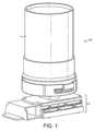
図1は、ばら材料を貯蔵し、計量し、分配するためのデバイス10を示す。このデバイスは、上記ばら材料を貯蔵するための容器1と、投入ユニット2とを備える。この容器の底部は、ばら材料を供給するために、投入ユニット2と協働する。 FIG. 1 shows a
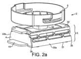
図2aは、図1のデバイス10の投入ユニット2の分離図である。投入ユニットは、ハウジング3を備える。このハウジングは、底壁31、頂壁32、2つの側壁33a、33b、前端部34、及び後端部35を備える。 FIG. 2a is an isolated view of the
頂壁32は、容器の底部(図1に示される)と協働するポート36を備える。ハウジング3及びそのポート36は、容器の底部を保持するように構成された受容領域5を介して容器と協働する。したがって、容器1は、ハウジングのポート36を介してばら材料を投入ユニット2に供給する。図示されるように、受容領域5は、その側壁に、容器の対応するピン部又は隆起部と協働するように設計されたスリット又はガイドトラックを備えることができる。
投入ユニットは、ハウジング3内で摺動することができる引き出し4を備える。図2aでは、引き出しは、完全にハウジング内にあり、つまり計量位置にある。この位置において、ばら材料が、容器から投入ユニット内に導入され、引き出しの計量キャビティ内で計量される。 The dosing unit comprises a
図3は、図2aと同じ計量位置にある投入ユニットの上面図であり、ポート36の下に配置され、ばら材料で充填することが可能な、この計量キャビティ43を示す。 FIG. 3 is a top view of the dosing unit in the same metering position as in FIG. 2a, showing this
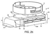
図2bは、引き出し4がハウジング3から部分的に引き出され、分配位置にある、同じ投入ユニット2の図である。引き出しは、計量キャビティ43がハウジングの外に配置され、計量された投入量のばら材料を下方に分配することができるように、引き出される。 Figure 2b is a view of the
図4aは、図2bと同じ分配位置にある投入ユニットの底面図であり、ばら材料を分配することが可能な、この計量キャビティ43の開放された底部を示す。 Figure 4a is a bottom view of the dosing unit in the same dispensing position as Figure 2b, showing the open bottom of this
図4bは、同じ分配位置にある投入ユニットの上面図であり、ポート36が引き出しの頂壁42によってどのように閉鎖されるかを示す。 Figure 4b is a top view of the dosing unit in the same dispensing position, showing how the
図5a及び図5bは、前述の各図の投入ユニットのハウジング3の斜視図である。これらの図では、受容領域5は取り外されている。ハウジング3は、4つの壁、すなわち、底壁31、頂壁32、及び2つの側壁33a、33bを備える。頂壁32及び底壁31は、設計により本質的に平行である。しかしながら、製造時、特に射出成形によって製造される場合、これらの壁の平行度は完全でない場合がある。具体的には、全体的には平行性が存在し得るが、局所的には、頂壁又は底壁の一部の領域が完全に平面ではないことがあり、ハウジング及び引き出しの壁の間に局所的な空隙のリスクが生じる。これらの空隙は、互いに協働して、空気、湿気、及び粉末の通り道を作り出すことがある。 Figures 5a and 5b are perspective views of the
ハウジング3は、ハウジングの内外への引き出しの移動を可能にするために、その前端部34において開放されている。好ましくは、底壁31は、前端部34において、引き出しの計量キャビティが接触する領域に鋭縁部38を有する。この鋭縁部は、投入量のばら材料を分配した後に、キャビティの縁部に付着したままであるばら材料を廃棄することができる。 The
ハウジング3は、その後端部35において開放されているが、頂壁の後端部から延びている壁の形態の停止部材37を備える。この部材は、引き出しを、頂壁のポート36の直下に計量キャビティがあるその計量位置に配置することを可能にする。代替的な実施形態によれば、後端部は、頂壁と底壁との間に延びている壁であってもよいが、このような実施形態は、特にそのようなハウジングを清掃するのにあまり利便性がよくないため、あまり好ましくない。 The
ハウジングの2つの側壁33a、33bは、構造によって垂直方向に収縮している。この収縮により、ハウジングの側壁33a、33bは伸縮性である。すなわち、引き出しがより大きい高さを有するものの、側壁33a、33bが拡張して、ハウジング内で引き出しを摺動させることができる。引き出しがハウジング内に配置されると、ハウジングの側壁が拡張され、これらの側壁は、反対方向の収縮力を引き出しに及ぼし、ハウジング内に引き出しをクランプする。このクランプの結果としては、第1に、気密性及び計量キャビティと大気との接触の制限があり、第2に、ハウジング内での引き出しの自由な移動の抑制がある。 The two
図5aに示される実施形態では、側壁33a、33bの収縮は、それらの壁の設計によるものである。すなわち、各壁は、ハウジングの前端部34から後端部35までこの側壁に沿って長手方向に延びているロッド331aを備える。この長手方向は、ハウジング内での引き出しの並進方向に対応する。このロッドは、頂壁及び底壁の長手方向に平行である。 In the embodiment shown in Figure 5a, the contraction of the
このロッド331aは、例示された実施形態では6つのピラーである、上部及び下部ピラー332aによって、側壁33aに取り付けられている。これらのピラーは、ロッドの長さに沿って上下に交互に配置される。その結果、ロッドは、交互に、すなわち、上部ピラーがいずれの下部ピラーにも面しておらず、逆もまた同様であるように配置された3つの上部ピラー及び3つの下部ピラーを介して側壁に取り付けられる。 This
図5a、図5bに示されるように、ハウジングは、引き出しがハウジング内に滑り込まされていないため、非拡張状態にある。ハウジングの内法高さ(すなわち、頂壁の下面と下壁の上面との間の高さ)は、h1である。図示の例では、この高さh1は約20mmである。As shown in Figures 5a, 5b, the housing is in an unexpanded state as the drawer has not been slid into the housing. The inner height of the housing (ie, the height between the bottom surface of the top wall and the top surface of the bottom wall) ish1 . In the example shown, this heighth1 is approximately 20 mm.
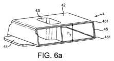
図6a及び図6bは、前述の各図の投入ユニットの引き出し4の斜視図である。引き出しは、底壁41及び頂壁42を備える。頂壁42及び底壁41は、設計により平行である。しかしながら、製造時、特に射出成形によって製造される場合、これらの壁の平行度は完全でない場合がある。具体的には、全体的には平行性が存在し得るが、局所的には、頂壁又は底壁の一部の領域が完全に平面ではないことがあり、ハウジング及び引き出しの壁の間に局所的な空隙のリスクが生じる。 Figures 6a and 6b are perspective views of the
引き出しは、頂壁から底壁まで延びており、ばら材料を受容し、投入し、分配するように設計された計量キャビティ43を備える。 The drawer extends from the top wall to the bottom wall and comprises a
引き出しの外法高さ(すなわち、頂壁の上面と底壁の下面との間の距離)は、h2であり、h2は、ハウジングの内法高さh1よりわずかに大きい。図示の例では、高さh1とh2との差は0.1mmである。The outer heightof the drawer (ie, the distance between the upper surface of the top wall and the lower surface of the bottom wall) ish2 , which is slightly greater than the inner height of the housingh1 . In the example shown, the difference between heights h1 and h2 is 0.1 mm.
この引き出し4が図5a、図5bのハウジング3内を摺動すると、小さな高さの差(h2-h1)及びハウジングの側壁の垂直方向の収縮は、間に引き出しが存在することにより、これらの側壁を垂直方向に拡張することになる。次いで、ハウジングの収縮した壁は、引き出しに収縮力を及ぼし、引き出しの上部外表面及び底部外表面をクランプして、引き出し及びハウジングの頂壁同士の間並びに引き出し及びハウジングの底壁同士の間に気密性をもたらす。キャビティ43内のばら材料に空気及び/又は湿気が到達するリスクが制限され、表面の間のキャビティから塵埃又は粉末が漏出するリスクもまた制限される。As this
更に、この収縮は、投入ユニットの向きによって自然落下に対する引き出しの保持を可能にするようにも設計される。 Furthermore, this shrinkage is also designed to allow retention of the drawer against free fall depending on the orientation of the dosing unit.
更に、製造後、引き出し及びハウジングが元々設計された寸法を正確に有していない場合でも、具体的には、ハウジング及び引き出しの底壁と頂壁との間の平行度が完全ではない場合でも、ハウジングの側壁の収縮により、引き出しとハウジングとの間の気密性が保証される。実際に、引き出しの底壁41及び頂壁42が完全に平行ではなく、その結果、引き出しの一部が引き出しの残りの部分よりも厚い場合、ハウジングの厚さは、引き出しがハウジング内を摺動するに際に、多少局所的に増加することが可能である。図5a、図5bに示されるハウジングの特定の実施形態では、ロッド331a、331bのうちの少なくとも1つが、少なくとも局所的に屈曲され、ハウジングの厚さを増加させることができる。例えば、ロッドは、厚みのある引き出しが内側に滑り込まされたときにロッドが波形状を有するような限度まで、ばね板のように曲げることができる。 Moreover, even if the drawers and housings do not have exactly the dimensions for which they were originally designed after manufacture, in particular even if the parallelism between the bottom and top walls of the housings and drawers is not perfect. , the contraction of the sidewalls of the housing ensures tightness between the drawer and the housing. In fact, if the
ハウジングが作製される材料の性質によって、及びハウジングの寸法によって、必要な収縮をもたらすようにロッドの形状及び太さを適合させることができる。 Depending on the nature of the material from which the housing is made and the dimensions of the housing, the shape and thickness of the rod can be adapted to provide the necessary shrinkage.
好ましくは、ハウジングの収縮の強度は、ハウジング内外への引き出しの移動を過度に強く抑制しないように制御される。反対に、好ましくは、移動はソフトかつ容易であるように保たれる。 Preferably, the strength of the retraction of the housing is controlled so as not to constrain movement of the drawer in and out of the housing too strongly. On the contrary, movement is preferably kept soft and easy.
図1~図6bに示される投入ユニットの特定の実施形態は、プラスチックで製造され、その寸法は、
-ハウジングの内法高さh1が20mm、
-引き出しの外法高さh2が20.1mmであり、
-ロッド331a、331bは、85mmの長さと及び5mm2の横断面を有する。The particular embodiment of the dosing unit shown in FIGS. 1-6b is made of plastic and its dimensions are:
- the inner heighth1 of the housing is 20 mm,
- the external heighth2 of the drawer is 20.1 mm,
- The
一般に、側壁の各要素の寸法は、ハウジングが作製される材料の性質に適合される。 Generally, the dimensions of each element of the side wall are adapted to the properties of the material from which the housing is made.
投入装置のハウジングの側壁の収縮の更なる利点は、この特性により、本質的に平行な頂壁及び底壁を有するハウジングの射出成形による製造が可能になることである。 A further advantage of the shrinkage of the sidewalls of the housing of the dosing device is that this characteristic allows the manufacture by injection molding of a housing having essentially parallel top and bottom walls.
実際に、射出成形の分野では、このハウジングなどの本質的に平行な壁を備えた単一の材料片は、このような材料片の一部を破壊することなく型から取り出すことがほとんどできないため、製造できないことが現在知られている。実際には、ハウジングの製造には2つの部品から作製される型が必要であり、第1の部品は、ハウジングの外部部分を設計するため、第2の部品は、ハウジングの内部部分を設計するためのものである。射出中、第2の部品は、第1の部品の内側に配置され、プラスチックが、内部部分と外部部分との間の間隙に射出される。プラスチックが硬くなると、2つの型部品がそこから分離される。ハウジングが本質的に平行な頂壁及び底壁を有するように設計されている場合、射出され成形されたハウジング内に配置された型の第2の部品の取り外しは極めて困難であり、通常、成形されたハウジングの破壊をもたらす。 Indeed, in the field of injection molding, a single piece of material with essentially parallel walls, such as this housing, can hardly be removed from the mold without destroying part of such a piece of material. , is now known to be unmanufacturable. In practice, the manufacture of the housing requires a mold made from two parts, the first designing the outer part of the housing and the second designing the inner part of the housing. It is for During injection, the second part is placed inside the first part and plastic is injected into the gap between the inner part and the outer part. When the plastic hardens, the two mold parts separate from it. If the housing is designed with essentially parallel top and bottom walls, the removal of the second part of the mold placed within the injected and molded housing is extremely difficult and is usually result in the destruction of the housing that has been detonated.
このような理由で、現在、わずかなテーパ角を有する、いわゆる平行壁を設計することが知られている。その結果、このテーパ角は、射出された材料片を型から容易に取り外すことを可能にするが、結果として得られる材料片は、本質的に平行な壁を有することができない。この平行度は引き出しとハウジングとの間の気密性を得るために必須であるため、これは本発明の投入ユニットの概念において致命的な問題である。 For this reason, it is now known to design so-called parallel walls with a slight taper angle. As a result, while this taper angle allows the injected piece of material to be easily removed from the mold, the resulting piece of material cannot have essentially parallel walls. This is a critical issue in the dosing unit concept of the present invention, as this parallelism is essential for obtaining airtightness between the drawer and the housing.
しかし、ハウジングが収縮した壁を有していれば、本質的に平行な頂壁及び底壁を有するハウジングを、型からのハウジングの取り外しに関連するいかなる問題もなく、射出成形によって設計及び製造することができる。実際に、ハウジングの側壁の収縮特性が、ばね効果及び可撓性をもたらし、型から取り外す間のハウジングの破壊を回避する。 However, if the housing has shrunk walls, a housing with essentially parallel top and bottom walls can be designed and manufactured by injection molding without any problems associated with removing the housing from the mold. be able to. In fact, the shrinkage properties of the sidewalls of the housing provide a spring effect and flexibility to avoid breaking the housing during removal from the mold.
図6a及び図6bに示されるように、好ましくは、引き出し45の後端部は丸みを帯びた角部451を有する。したがって、引き出しの最後端部は、通常、ハウジングの内法高さよりもわずかに小さい、低められた高さを有しており、ハウジングの側壁33a、33bはまだ拡張していないがハウジング内に引き出しを容易に導入することができる。 Preferably, the rear end of the
引き出しは、通常、手動又は電動式のいずれかで引き出しを引くことができるように、舌状の引張部材44を備える。 The drawers are usually provided with tongue-
図6a及び図6bに示されるように、好ましくは、計量キャビティは、頂壁及び底壁においてそれぞれキャビティの側縁部が頂壁及び底壁の側縁部から離れるように、引き出し内に配置されている。 As shown in Figures 6a and 6b, the metering cavity is preferably arranged in the drawer such that the side edges of the cavity are away from the side edges of the top and bottom walls respectively at the top and bottom walls. ing.
図7aは、図1~図5bのハウジングに代わるハウジングの第2の実施形態を示す。このハウジングの各側壁33a、33bは、蛇腹状部分333a、333bを含む。蛇腹は、ハウジングの側壁の垂直方向の収縮をもたらすように構成されている。 Figure 7a shows a second embodiment of a housing which is an alternative to the housing of Figures 1-5b. Each
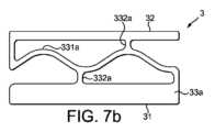
図7b~図7eは、図1~図5bのハウジングに代わる様々なハウジングの実施形態を示す。 Figures 7b-7e show various alternative housing embodiments to the housing of Figures 1-5b.
種々の実施形態は、側壁33aの設計によって区別する。他方の側壁33bは図示されていないが、図示した壁33aと同じ設計を有する。これらの種々の設計は、両方の側壁に収縮効果をもたらす。 Various embodiments are distinguished by the design of
図7bでは、側壁33aの設計は、ロッド3が一直線ではなく波線331aによって置き換えられていることを除いて、図1~図5bに示される側壁と類似している。 In Figure 7b, the design of
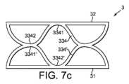
図7cでは、側壁33aは2つの波線334、334’を含み、一方は側壁の上縁部に取り付けられており、他方は側壁の底縁部に取り付けられており、各波はハウジングの前端部から後端部まで延びている。これらの2つの波は、同様の設計を有し、それらの山部3341’と谷部3342で連なっている。 In Figure 7c, the
図7dでは、側壁33aは、複数の波線334、334’(図示された例では4つの波線)を含み、各波はハウジングの前端部から後端部まで延びており、各波は、波同士の山部と谷部とが連なるように、隣の近接した波線に対してずれている。その結果、壁の設計は、穴335からなるメッシュを含む。 In FIG. 7d, the
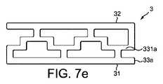
図7eでは、側壁33aの設計は、ロッドが一直線ではなく凹凸状の線331aによって置き換えられていることを除いて、図1~図5bに示される側壁と類似している。 In Figure 7e, the design of
これらの全ての図において、ハウジングの各側壁は、穴335からなるメッシュを含んでいる。メッシュは、側壁に沿って長手方向に整列された、少なくとも2列の穴を含み、側部で接触している2つの列について、一方の列の穴が、他方の列の穴とずれている。これらの構成が、ハウジング内で引き出しをクランプすることができる拡張可能な側壁を提供する。 In all these figures, each side wall of the housing contains a mesh of
図8は、飲料生成装置100を示す。この装置は、飲料調製チャンバ7を含む。このチャンバは、飲料原材料及びチャンバに入る水性液体(好ましくは水)から飲料を生成するように構成されている。 FIG. 8 shows a
飲料原材料は、原材料を、貯蔵し、計量し、分配するための上記のようなデバイスの容器1内に貯蔵される。容器1は、常置のホッパー又は飲料原材料を収容する使い捨てパッケージであってもよい。 Beverage ingredients are stored in a
飲料原材料の投入量は、デバイスの投入ユニット2によって計量され、分配される。投入ユニットは、一般にチャンバの上部開口部内への自然落下により、チャンバ7内に投入量の飲料原材料を分配する。 The dosage of beverage ingredients is metered and dispensed by the
好ましくは、原材料は、可溶性原材料であり、典型的には、インスタント水溶きコーヒーなどの乾燥飲料粉末である。その場合、チャンバ7は、水性液体中での原材料の溶解を可能にする混合チャンバである。 Preferably, the ingredient is a soluble ingredient, typically a dry beverage powder such as instant coffee. Chamber 7 is then a mixing chamber that allows dissolution of the raw materials in the aqueous liquid.
あるいは、原材料は、焙煎して粉にしたコーヒー粉末であってもよい。その場合、チャンバ7は、コーヒーを水で抽出することを可能にする淹出チャンバである。 Alternatively, the raw material may be roasted and ground coffee powder. Chamber 7 is then a brewing chamber that allows the coffee to be brewed with water.
投入ユニット2は手動で作動させることができる。あるいは、投入ユニット、より具体的には投入ユニットの引き出しは、モータによって作動され、コントローラ108及びコマンド109によって促されるように自動的に作動されることができる。 The
チャンバ7内に水、より具体的には熱水を供給することができるように液体、好ましくは水供給システムがマシン内に設けられている。 A liquid, preferably water, supply system is provided in the machine so as to be able to supply water, more particularly hot water, into the chamber 7 .
図示した実施形態では、水供給システム105は、
新鮮な水を補給することができる、又は、最終的には水道水に接続され得るタンク101と、
タンク101から水を圧送するための、送水ポンプ102とを備える。ポンプは、ピストンポンプ、ダイヤフラムポンプ又は蠕動ポンプなどの任意のタイプのポンプであってもよい。In the illustrated embodiment, the
a
A
圧送された水を加熱するためのサーモブロック若しくはカートリッジタイプの加熱器などの、水加熱器103と、あるいは、又はこれに加えて、マシンは、加熱器を迂回するライン上に水冷却器を備えてもよく、
逆止め弁104、を備える。A
A
最終的に、水は、管106によって、チャンバ7内に供給される。 Finally, water is fed into chamber 7 by
図示されるように、チャンバ7は、飲料液体を受けるために飲用カップ110を配置したサービストレイ107の真上に配置することができる。 As shown, the chamber 7 can be positioned directly above a
コントローラ108は、ユーザが、本装置上のコマンド109を作動させると、又はコマンド109を押すように促されると、投入ユニット2による飲料原材料の投入とポンプ102による液体の投入とを調整することができる。
一般に、飲料原材料の投入は、液体がチャンバ内に導入される前に起こる。引き出しは、この投入の終了時に、チャンバの上部開口部から離れた計量位置に再び配置されることが好ましい。その結果、飲料調製中に水滴又は湿気がこのキャビティに到達するリスクがなくなる。 In general, dosing of beverage ingredients occurs before liquid is introduced into the chamber. At the end of this dosing, the drawer is preferably again placed in a weighing position away from the top opening of the chamber. As a result, there is no risk of water droplets or moisture reaching this cavity during beverage preparation.
ばら材料を貯蔵し、計量し、分配するための、図1に示されるようなデバイスを使用した上記飲料生成装置を、熱帯条件を表す温度30℃及び相対湿度70%の気候室内で試験した。容器を、凝集水溶きコーヒー(NESCAFE Red Cup(登録商標))で充填した。試験は4週間継続し、2杯のコーヒー飲料を毎日抽出した。コーヒー飲料は、凝集水溶きコーヒー2g及び熱水140mLから調製した。 The beverage production apparatus described above using a device as shown in Figure 1 for storing, weighing and dispensing bulk material was tested in a climatic chamber with a temperature of 30°C and a relative humidity of 70% representing tropical conditions. A container was filled with agglomerated coffee dissolved in water (NESCAFE Red Cup®). The trial lasted 4 weeks and two coffee drinks were extracted daily. A coffee drink was prepared from 2 g of flocculated coffee and 140 mL of hot water.
4週間後:
-投入ユニットの詰まりは認められなかった。
-粉末の投入精度は影響を受けなかった。
-飲料の味は、全くオフノートがなく、飲料基準に近いプロファイルを示した。4 weeks later:
- No clogging of the dosing unit was observed.
- Powder dosing accuracy was not affected.
- The taste of the beverage showed a profile close to the beverage standard without any off-notes.
調製したコーヒーの重量を測定し、サンプルのブリックスを測定することにより投入精度を測定した。次いで、検量線を参照することにより、調製された飲料ごとに飲料の乾燥物を計算した。 Dosing accuracy was measured by weighing the prepared coffee and measuring the Brix of the sample. Beverage dry matter was then calculated for each prepared beverage by reference to the calibration curve.
この試験は、投入ユニットによってもたらされる気密性を確認するものである。この気密性により、マシンが頻繁に使用されず(1日2回)、投入量のコーヒーが2回の飲料調製の間に計量キャビティに貯蔵されたままでも、飲料の品質は良好なままである。 This test confirms the tightness provided by the dosing unit. Due to this tightness, even if the machine is not used frequently (twice a day) and the dose of coffee remains stored in the metering cavity between two beverage preparations, the beverage quality remains good. .
このクランピングにより、引き出しの底壁及び引き出しの頂壁は、それぞれハウジングの底壁に沿って及びハウジングの頂壁に沿ってぴったりと収まって摺動し、これらの2つの要素間の気密性を改善する。この気密性により、投入ユニットが使用されずに計量位置に配置されているときに計量キャビティ内にばら材料が存在する場合、空気及び水分は、上記キャビティ及びばら材料にほとんど到達することができない。その結果、ばら材料の特性は影響を受けず、そのばら材料から調製される飲料の品質は良好である。 This clamping causes the drawer bottom wall and the drawer top wall to slide snugly along the housing bottom wall and along the housing top wall, respectively, to ensure an airtight seal between these two elements. Improve. Due to this tightness, air and moisture can hardly reach said cavity and bulk material if there is bulk material in the metering cavity when the dosing unit is not in use and is placed in the metering position. As a result, the properties of the bulk material are not affected and the beverages prepared from the bulk material are of good quality.
本発明のデバイスは、投入ユニットの引き出しを、別の計量キャビティを有する別の引き出しと交換する、又は更にメンテナンスのために交換する能力をもたらすという利点を有する。引き出しがハウジング内にぴったり収まるように完全に設計されていなくても、ハウジングは、その不完全な設計を補償し、気密性を保証することができる。 The device of the invention has the advantage of providing the ability to replace the drawer of the dosing unit with another drawer with another metering cavity or even for maintenance. Even if the drawer is not perfectly designed to fit within the housing, the housing can compensate for the imperfect design and ensure tightness.
本発明は、上記で例示された実施形態を参照して説明されているが、特許請求される本発明は、決してこれらの例示された実施形態によって限定されるものではないことが理解されるであろう。 Although the invention has been described with reference to the exemplary embodiments above, it should be understood that the claimed invention is in no way limited by these exemplary embodiments. be.
本発明の範囲を逸脱することなく、「特許請求の範囲」で定義されるような、変形及び修正が実施可能である。更に、特定の特徴に対して既知の等価物が存在する場合、かかる等価物は、本明細書中で具体的に言及されているかのように組み込まれるものである。 Variations and modifications, as defined in the claims, can be made without departing from the scope of the invention. Further, where known equivalents exist to particular features, such equivalents are incorporated herein as if specifically referenced.
本明細書で使用するとき、用語「備える」、「備えている」、及び同様の語は、排他的又は包括的な意味で解釈されるべきではない。換言すれば、これらは、「~を含むが、それらに限定されない」ことを意味するものとする。 As used herein, the terms “comprising,” “comprising,” and similar terms are not to be interpreted in an exclusive or inclusive sense. In other words, they shall mean "including, but not limited to."
1 容器
2 投入ユニット
3 ハウジング
31 底壁
32 頂壁
33a,33b 側壁
331a,331b ロッド
332a,332b ピラー
333a,333b 蛇腹状部分
334,334’ 波線
3341 頂部
3342 谷部
34 前端部
35 後端部
36 ポート
37 停止部材
38 鋭縁部
4 引き出し
41 底壁
42 頂壁
43 計量キャビティ
44 引張部材
45 後端部
451 丸みを帯びた角部
5 受容領域
6 モータ
7 飲料調製チャンバ
10 貯蔵し、計量し、分配するためのデバイス
100 飲料調製装置
101 タンク
102 ポンプ
103 加熱器
104 弁
105 水供給システム
106 パイプ
107 サービストレイ
108 コントローラ
109 コマンド
110 飲用カップREFERENCE SIGNS
Claims (16)
Translated fromJapanese前記ばら材料を貯蔵するための容器(1)と、
前記容器からのばら材料を計量し、計量された投入量のばら材料を分配するための投入ユニット(2)と、を備え、
前記容器の底部は、ばら材料を前記投入ユニットに供給するために、前記投入ユニットと協働し、
前記投入ユニット(2)は、
底壁(31)、頂壁(32)、2つの側壁(33a、33b)、前端部(34)、及び後端部(35)を備えるハウジング(3)であって、前記頂壁は、前記容器の底部と協働するポート(36)を備える、ハウジングと、
計量位置と分配位置との間で、前記ハウジングの前記前端部(34)を通って前記ハウジング(3)の内外に長手方向に摺動することができる引き出し(4)と、を備え、
前記引き出しは、
底壁(41)及び頂壁(42)と、
前記頂壁から前記底壁まで延びている計量キャビティ(43)であって、前記引き出しが前記計量位置にあるときに、前記ハウジングの前記ポート(36)からばら材料を受け、前記引き出しが前記分配位置にあるときに、前記計量された量のばら材料を排出するように設計された計量キャビティ(43)と、を備え、
前記ハウジングの前記側壁(33a、33b)は、構造によって垂直方向に収縮しており、前記ハウジングの前記側壁(33a、33b)は、前記ハウジング内での前記引き出しの前記長手方向の摺動の動きに応じて垂直方向に拡張することができ、
前記ハウジングが非拡張状態にあるとき、前記引き出しの外法高さ(h2)は、前記ハウジングの内法高さ(h1)よりも大きく、
前記引き出し(4)が前記ハウジング内に配置されるときに、前記ハウジングの前記側壁(33a、33b)の前記収縮により、前記引き出しが前記ハウジングの前記頂壁(32)及び前記底壁(31)とクランプ係合するようになっている、デバイス。A device (10) for storing, weighing and dispensing bulk material, comprising:
a container (1) for storing said bulk material;
a dosing unit (2) for metering bulk material from said container and dispensing a metered dose of bulk material;
the bottom of the container cooperates with the dosing unit to supply bulk material to the dosing unit;
The input unit (2) is
A housing (3) comprising a bottom wall (31), a top wall (32), two side walls (33a, 33b), a front end (34) and a rear end (35), said top wall comprising said a housing comprising a port (36) cooperating with the bottom of the container;
a drawer (4) longitudinally slidable into and out of said housing (3) through said front end (34) of said housing between a metering position and a dispensing position;
Said withdrawal is
a bottom wall (41) and a top wall (42);
A metering cavity (43) extending from said top wall to said bottom wall for receiving bulk material from said port (36) of said housing when said drawer is in said metering position and said drawer is adapted for said dispensing. a metering cavity (43) designed to eject said metered amount of bulk material when in position;
The sidewalls (33a, 33b) of the housing are vertically contracted by construction, and the sidewalls (33a, 33b) of the housing are adapted for the longitudinal sliding movement of the drawer within the housing. can be expanded vertically depending on the
an outer height (h2 ) of the drawer is greater than an inner height (h1 ) of the housing when the housing is in an unexpanded state;
When said drawer (4) is placed in said housing, said contraction of said side walls (33a, 33b) of said housing causes said drawer to move between said top wall (32) and said bottom wall (31) of said housing. A device adapted for clamping engagement with.
前記メッシュは、前記側壁に沿って長手方向に整列された、少なくとも2列の穴を含み、
側部で接触している2つの列について、一方の列の前記穴が、他方の列の前記穴とずれている、請求項1~6のいずれか一項に記載のデバイス。each side wall (33a, 33b) of said housing comprising a mesh of holes (335);
the mesh includes at least two rows of holes longitudinally aligned along the sidewalls;
A device according to any one of claims 1 to 6, wherein for two rows in lateral contact, the holes in one row are offset from the holes in the other row.
前記ロッドは、前記ハウジングの前記前端部(34)から前記後端部(35)まで前記側壁に沿って長手方向に延びており、
前記ロッドは、上部ピラー(332a)及び下部ピラー(332b)によって前記側壁に取り付けられており、
前記上部ピラー及び前記下部ピラーは、前記ロッドの長さに沿って交互に配置されている、請求項1~6のいずれか一項に記載のデバイス。each side wall (33a, 33b) of said housing comprises a rod (331a, 331b);
said rod extends longitudinally along said side wall from said front end (34) to said rear end (35) of said housing;
The rod is attached to the sidewall by an upper pillar (332a) and a lower pillar (332b),
A device according to any preceding claim, wherein the upper andlower pillars are alternately arranged along the length of the rod.
飲料原材料をばらで貯蔵し、計量し、分配するための前記デバイスが、前記飲料原材料が前記チャンバ内に分配されるように前記飲料調製チャンバと協働する、請求項13に記載の飲料調製システム。said system comprising a beverage preparation chamber (7) connected to at least one liquid supply;
14. The beverage preparation system of claim 13, wherein the device for bulk storing, metering and dispensing beverage ingredients cooperates with the beverage preparation chamber such that the beverage ingredients are dispensed into the chamber. .
前記引き出し(4)を前記計量位置に配置するステップと、次いで
前記引き出し(4)を前記分配位置に配置するステップと、次いで
前記飲料調製チャンバ(7)に液体を導入するステップと、を含む、方法。A method for producing a beverage in the beverage preparation system of claim 14, comprising:
placing said drawer (4) in said metering position, then placing said drawer (4) in said dispensing position, and then introducing liquid into said beverage preparation chamber (7), Method.
Applications Claiming Priority (3)
| Application Number | Priority Date | Filing Date | Title |
|---|---|---|---|
| EP17181898 | 2017-07-18 | ||
| EP17181898.2 | 2017-07-18 | ||
| PCT/EP2018/069287WO2019016149A1 (en) | 2017-07-18 | 2018-07-16 | Device for metering and dispensing bulk material |
Publications (2)
| Publication Number | Publication Date |
|---|---|
| JP2020527517A JP2020527517A (en) | 2020-09-10 |
| JP7245224B2true JP7245224B2 (en) | 2023-03-23 |
Family
ID=59366322
Family Applications (1)
| Application Number | Title | Priority Date | Filing Date |
|---|---|---|---|
| JP2020501816AActiveJP7245224B2 (en) | 2017-07-18 | 2018-07-16 | Device for metering and dispensing bulk material |
Country Status (5)
| Country | Link |
|---|---|
| EP (1) | EP3654808B1 (en) |
| JP (1) | JP7245224B2 (en) |
| CN (1) | CN110799071B (en) |
| ES (1) | ES2897073T3 (en) |
| WO (1) | WO2019016149A1 (en) |
Families Citing this family (5)
| Publication number | Priority date | Publication date | Assignee | Title |
|---|---|---|---|---|
| EP3826517B1 (en) | 2018-07-24 | 2022-08-31 | Société des Produits Nestlé S.A. | Beverage preparation method |
| WO2020173722A1 (en) | 2019-02-25 | 2020-09-03 | Société des Produits Nestlé S.A. | Cold beverage dispensing system |
| US12213616B2 (en) | 2019-04-04 | 2025-02-04 | Societe Des Produits Nestle S.A. | Beverage dispenser with powder container |
| BR112021021265A2 (en) | 2019-05-07 | 2021-12-21 | Nestle Sa | Powdered food or beverage composition |
| US20220279958A1 (en) | 2019-07-29 | 2022-09-08 | Societe Des Produits Nestle S.A. | Method for preparing milk and coffee based beverages |
Citations (2)
| Publication number | Priority date | Publication date | Assignee | Title |
|---|---|---|---|---|
| US20040173643A1 (en) | 2003-03-06 | 2004-09-09 | Yuri Tuvim | Device for storing, measuring and dispensing granular and powder materials |
| JP2007040706A (en) | 2005-07-29 | 2007-02-15 | Yuji Kamishita | Fixed quantity taking-out device and container for package |
Family Cites Families (28)
| Publication number | Priority date | Publication date | Assignee | Title |
|---|---|---|---|---|
| GB641388A (en)* | 1947-02-27 | 1950-08-09 | Cory Corp | Beverage brewer |
| JPS5046556U (en)* | 1973-08-28 | 1975-05-09 | ||
| US4085870A (en)* | 1976-11-05 | 1978-04-25 | Holdt J W Von | Dispensing drawer assembly |
| DE2920747C3 (en)* | 1979-05-22 | 1982-02-11 | DAGMA Deutsche Automaten- und Getränkemaschinen GmbH & Co KG, 2067 Reinfeld | Device for sealingly connecting a transport container to the frame-mounted, upwardly open receptacle of a device for the metered dispensing of liquids in devices for dispensing beverages |
| US4293081A (en)* | 1978-08-03 | 1981-10-06 | Dagma Deutsche Automaten Und Getrankemaschinen Gmbh & Co. Kg | Method and device for metered dispensing of liquids, in particular concentrates or syrups, for the production of beverages |
| IL64246A0 (en) | 1981-11-09 | 1982-02-28 | Solomon Arie | Assembly for storing,metering and dispensing of granular material |
| SE455735B (en)* | 1986-12-22 | 1988-08-01 | Jede Automater Ag | DOSAGE DEVICE FOR POWDER MATERIAL |
| FR2702452B1 (en) | 1993-03-09 | 1995-06-16 | Dumont Max | DEVICE FOR DISPENSING DOSES OF POWDER PRODUCTS. |
| US5685461A (en)* | 1995-05-23 | 1997-11-11 | Mitchell; Terry | Apparatus for dispensing a uniform volume of granular material |
| US6450371B1 (en)* | 2002-01-24 | 2002-09-17 | Yury Sherman | Device for measuring, dispensing and storing of granular and powder materials |
| US6880732B2 (en)* | 2003-01-15 | 2005-04-19 | Christian T. Scheindel | Piston for pressurized container |
| US7353970B1 (en)* | 2004-10-13 | 2008-04-08 | Harrison-Coats Daneen Y | Food and beverage article dispenser |
| US20070210119A1 (en)* | 2006-03-10 | 2007-09-13 | Square 1 Product Development | Dispensing cap |
| EP1932457A1 (en) | 2006-12-11 | 2008-06-18 | Nestec S.A. | Device and method for producing a frothed liquid from soluble ingredients and diluent |
| ATE484224T1 (en) | 2007-06-28 | 2010-10-15 | Nestec Sa | CONTAINER FOR STORAGE AND UNLOADING BULK GOODS |
| US20090229472A1 (en)* | 2008-03-12 | 2009-09-17 | Ferrara Jr Daniel A | Brewing system and packaging |
| AU2010297421A1 (en) | 2009-09-23 | 2012-04-12 | Nestec S.A. | Container holding assembly and receiving assembly adapted for connecting a container to a machine |
| DK2621317T3 (en)* | 2010-09-28 | 2014-05-26 | Nestec Sa | DEVICE AND PROCEDURE FOR REMOVING A COVER FROM A BEVERAGE MANUFACTURER |
| GB201110848D0 (en)* | 2011-06-24 | 2011-08-10 | Mars Inc | Beverage preparation apparatus and method and beverage capsules for use therein |
| ES2550765T3 (en)* | 2011-10-17 | 2015-11-12 | Nestec S.A. | Expandable container for the preparation of a nutritional composition |
| AU2013341439B2 (en)* | 2012-11-10 | 2017-02-02 | Kraft Foods Group Brands Llc | Container with a removable measuring cap |
| US8906436B2 (en)* | 2013-03-15 | 2014-12-09 | Ptc-Innovations, Llc | Single serve beverage additive cartridge |
| CN103519688A (en)* | 2013-11-01 | 2014-01-22 | 倍适(北京)科技有限公司 | Drinking water bucket and drinking water device |
| CN106030670A (en)* | 2013-12-30 | 2016-10-12 | 保乐力加公司 | Beverage dispensing container, apparatus, system and method |
| WO2015117892A1 (en)* | 2014-02-06 | 2015-08-13 | Nestec S.A. | A capsule for improved beverage quality |
| US20160355327A1 (en)* | 2014-02-28 | 2016-12-08 | Sacmi Cooperativa Meccanici Imola Societa' Cooperativa | Cup for a coffee capsule |
| US9723942B2 (en)* | 2014-06-21 | 2017-08-08 | Palm Coffeemaker LLC | Brewing and filtering device for coffee and tea |
| US10602874B2 (en)* | 2015-06-16 | 2020-03-31 | Starbucks Corporation Dba Starbucks Coffee Company | Beverage preparation systems with brew chamber access mechanisms |
- 2018
- 2018-07-16JPJP2020501816Apatent/JP7245224B2/enactiveActive
- 2018-07-16ESES18742998Tpatent/ES2897073T3/enactiveActive
- 2018-07-16EPEP18742998.0Apatent/EP3654808B1/enactiveActive
- 2018-07-16WOPCT/EP2018/069287patent/WO2019016149A1/ennot_activeCeased
- 2018-07-16CNCN201880043419.1Apatent/CN110799071B/enactiveActive
Patent Citations (2)
| Publication number | Priority date | Publication date | Assignee | Title |
|---|---|---|---|---|
| US20040173643A1 (en) | 2003-03-06 | 2004-09-09 | Yuri Tuvim | Device for storing, measuring and dispensing granular and powder materials |
| JP2007040706A (en) | 2005-07-29 | 2007-02-15 | Yuji Kamishita | Fixed quantity taking-out device and container for package |
Also Published As
| Publication number | Publication date |
|---|---|
| JP2020527517A (en) | 2020-09-10 |
| EP3654808B1 (en) | 2021-08-25 |
| WO2019016149A1 (en) | 2019-01-24 |
| CN110799071A (en) | 2020-02-14 |
| ES2897073T3 (en) | 2022-02-28 |
| CN110799071B (en) | 2022-03-18 |
| EP3654808A1 (en) | 2020-05-27 |
Similar Documents
| Publication | Publication Date | Title |
|---|---|---|
| JP7245224B2 (en) | Device for metering and dispensing bulk material | |
| JP6356692B2 (en) | Beverage production device with improved receptacle injection means | |
| CN108024652B (en) | Removing capsules from capsule holders | |
| US10398257B2 (en) | Hot beverage maker with cleaning apparatus and related method | |
| CN107920684B (en) | Beverage machine with ergonomic outlet | |
| RU2561024C2 (en) | Device for beverage preparing and respective method | |
| JP5870103B2 (en) | Capsule holder or adapting device for adapting capsules in a capsule holder of a food preparation machine | |
| AU2015287111B2 (en) | Apparatus and method for preparing a brewed beverage | |
| US11559166B2 (en) | Beverage preparation and infusion system | |
| CN118830741A (en) | Beverage machine with ergonomic handling | |
| TW200819095A (en) | Capsule for the preparation of a beverage | |
| ITMO20130295A1 (en) | DRINKING MACHINE FOR DRINKS | |
| US20160309952A1 (en) | Set of consumables and beverage dispenser | |
| JP2022520147A (en) | A device for dosing and / or preparing a medium to be prepared, a container for accepting and administering an ingredient, a container for accepting and administering a fluid, and a corresponding system. | |
| US8481098B2 (en) | Device and process for the preparation of a beverage with enhanced aroma | |
| WO2014206868A1 (en) | Mixing chamber for producing beverages | |
| JP7382397B2 (en) | Beverage machine with actuated dispensing part | |
| US20170143156A1 (en) | A method and an apparatus for preparing a brewed beverage | |
| US20230363573A1 (en) | Collector of beverage machine with waste management | |
| US20180008085A1 (en) | System for refilling beverage dispenser with powder | |
| CN107787195B (en) | Capsule dispensing device | |
| US10765253B2 (en) | Brew basket for automated beverage brewing apparatus | |
| EP3342319A1 (en) | Machine preparing beverages from bulk ingredient and water | |
| WO2020001855A1 (en) | Beverage preparation machine with refillable multi-dose container |
Legal Events
| Date | Code | Title | Description |
|---|---|---|---|
| A621 | Written request for application examination | Free format text:JAPANESE INTERMEDIATE CODE: A621 Effective date:20210706 | |
| A977 | Report on retrieval | Free format text:JAPANESE INTERMEDIATE CODE: A971007 Effective date:20220609 | |
| A131 | Notification of reasons for refusal | Free format text:JAPANESE INTERMEDIATE CODE: A131 Effective date:20220621 | |
| A601 | Written request for extension of time | Free format text:JAPANESE INTERMEDIATE CODE: A601 Effective date:20220921 | |
| A521 | Request for written amendment filed | Free format text:JAPANESE INTERMEDIATE CODE: A523 Effective date:20221109 | |
| TRDD | Decision of grant or rejection written | ||
| A01 | Written decision to grant a patent or to grant a registration (utility model) | Free format text:JAPANESE INTERMEDIATE CODE: A01 Effective date:20230221 | |
| A61 | First payment of annual fees (during grant procedure) | Free format text:JAPANESE INTERMEDIATE CODE: A61 Effective date:20230310 | |
| R150 | Certificate of patent or registration of utility model | Ref document number:7245224 Country of ref document:JP Free format text:JAPANESE INTERMEDIATE CODE: R150 |