JP7242686B2 - Beverage preparation machine that recognizes capsules - Google Patents
Beverage preparation machine that recognizes capsulesDownload PDFInfo
- Publication number
- JP7242686B2 JP7242686B2JP2020541561AJP2020541561AJP7242686B2JP 7242686 B2JP7242686 B2JP 7242686B2JP 2020541561 AJP2020541561 AJP 2020541561AJP 2020541561 AJP2020541561 AJP 2020541561AJP 7242686 B2JP7242686 B2JP 7242686B2
- Authority
- JP
- Japan
- Prior art keywords
- capsule
- machine
- diffuser
- brewing
- light
- Prior art date
- Legal status (The legal status is an assumption and is not a legal conclusion. Google has not performed a legal analysis and makes no representation as to the accuracy of the status listed.)
- Active
Links
Images


Classifications
- A—HUMAN NECESSITIES
- A47—FURNITURE; DOMESTIC ARTICLES OR APPLIANCES; COFFEE MILLS; SPICE MILLS; SUCTION CLEANERS IN GENERAL
- A47J—KITCHEN EQUIPMENT; COFFEE MILLS; SPICE MILLS; APPARATUS FOR MAKING BEVERAGES
- A47J31/00—Apparatus for making beverages
- A47J31/44—Parts or details or accessories of beverage-making apparatus
- A47J31/4492—Means to read code provided on ingredient pod or cartridge
- A—HUMAN NECESSITIES
- A47—FURNITURE; DOMESTIC ARTICLES OR APPLIANCES; COFFEE MILLS; SPICE MILLS; SUCTION CLEANERS IN GENERAL
- A47J—KITCHEN EQUIPMENT; COFFEE MILLS; SPICE MILLS; APPARATUS FOR MAKING BEVERAGES
- A47J31/00—Apparatus for making beverages
- A47J31/44—Parts or details or accessories of beverage-making apparatus
- A47J31/52—Alarm-clock-controlled mechanisms for coffee- or tea-making apparatus ; Timers for coffee- or tea-making apparatus; Electronic control devices for coffee- or tea-making apparatus
- A47J31/521—Alarm-clock-controlled mechanisms for coffee- or tea-making apparatus ; Timers for coffee- or tea-making apparatus; Electronic control devices for coffee- or tea-making apparatus the electronic control being performed over a network, e.g. by means of a computer or a handheld device
- G—PHYSICS
- G06—COMPUTING OR CALCULATING; COUNTING
- G06N—COMPUTING ARRANGEMENTS BASED ON SPECIFIC COMPUTATIONAL MODELS
- G06N3/00—Computing arrangements based on biological models
- G06N3/02—Neural networks
- G06N3/04—Architecture, e.g. interconnection topology
- G06N3/0464—Convolutional networks [CNN, ConvNet]
- G—PHYSICS
- G06—COMPUTING OR CALCULATING; COUNTING
- G06N—COMPUTING ARRANGEMENTS BASED ON SPECIFIC COMPUTATIONAL MODELS
- G06N3/00—Computing arrangements based on biological models
- G06N3/02—Neural networks
- G06N3/08—Learning methods
- G—PHYSICS
- G06—COMPUTING OR CALCULATING; COUNTING
- G06N—COMPUTING ARRANGEMENTS BASED ON SPECIFIC COMPUTATIONAL MODELS
- G06N3/00—Computing arrangements based on biological models
- G06N3/02—Neural networks
- G06N3/08—Learning methods
- G06N3/09—Supervised learning
- G—PHYSICS
- G06—COMPUTING OR CALCULATING; COUNTING
- G06V—IMAGE OR VIDEO RECOGNITION OR UNDERSTANDING
- G06V10/00—Arrangements for image or video recognition or understanding
- G06V10/10—Image acquisition
- G06V10/12—Details of acquisition arrangements; Constructional details thereof
- G06V10/14—Optical characteristics of the device performing the acquisition or on the illumination arrangements
- G06V10/145—Illumination specially adapted for pattern recognition, e.g. using gratings
- G—PHYSICS
- G06—COMPUTING OR CALCULATING; COUNTING
- G06V—IMAGE OR VIDEO RECOGNITION OR UNDERSTANDING
- G06V10/00—Arrangements for image or video recognition or understanding
- G06V10/70—Arrangements for image or video recognition or understanding using pattern recognition or machine learning
- G06V10/82—Arrangements for image or video recognition or understanding using pattern recognition or machine learning using neural networks
- Y—GENERAL TAGGING OF NEW TECHNOLOGICAL DEVELOPMENTS; GENERAL TAGGING OF CROSS-SECTIONAL TECHNOLOGIES SPANNING OVER SEVERAL SECTIONS OF THE IPC; TECHNICAL SUBJECTS COVERED BY FORMER USPC CROSS-REFERENCE ART COLLECTIONS [XRACs] AND DIGESTS
- Y02—TECHNOLOGIES OR APPLICATIONS FOR MITIGATION OR ADAPTATION AGAINST CLIMATE CHANGE
- Y02W—CLIMATE CHANGE MITIGATION TECHNOLOGIES RELATED TO WASTEWATER TREATMENT OR WASTE MANAGEMENT
- Y02W90/00—Enabling technologies or technologies with a potential or indirect contribution to greenhouse gas [GHG] emissions mitigation
- Y02W90/10—Bio-packaging, e.g. packing containers made from renewable resources or bio-plastics
Landscapes
- Engineering & Computer Science (AREA)
- Theoretical Computer Science (AREA)
- Physics & Mathematics (AREA)
- Artificial Intelligence (AREA)
- General Physics & Mathematics (AREA)
- Evolutionary Computation (AREA)
- Food Science & Technology (AREA)
- General Engineering & Computer Science (AREA)
- Computing Systems (AREA)
- Health & Medical Sciences (AREA)
- Software Systems (AREA)
- General Health & Medical Sciences (AREA)
- Computational Linguistics (AREA)
- Molecular Biology (AREA)
- Data Mining & Analysis (AREA)
- Mathematical Physics (AREA)
- Biophysics (AREA)
- Biomedical Technology (AREA)
- Life Sciences & Earth Sciences (AREA)
- Computer Vision & Pattern Recognition (AREA)
- Multimedia (AREA)
- Medical Informatics (AREA)
- Databases & Information Systems (AREA)
- Apparatus For Making Beverages (AREA)
- Beverage Vending Machines With Cups, And Gas Or Electricity Vending Machines (AREA)
- Devices For Dispensing Beverages (AREA)
- Image Analysis (AREA)
- Image Processing (AREA)
- Tea And Coffee (AREA)
Description
Translated fromJapanese本発明の分野は、調製される飲料の原材料のカプセルを使用する飲料調製マシンに関する。本発明の分野は、特に、カプセルを使用し、例えば飲料調製パラメータを認識されたカプセルの種類に適合させるために、マシン内に挿入されたカプセルの種類を自動的に認識するように構成されている飲料調製マシンに関する。 The field of the invention relates to beverage preparation machines that use capsules of the ingredients of the beverage to be prepared. The field of the invention is particularly adapted to automatically recognize the type of capsules inserted into machines using capsules, e.g. to adapt the beverage preparation parameters to the recognized capsule type. beverage preparation machine.
本明細書の目的上、「飲料」は、茶、コーヒー、ホットチョコレート又はコールドチョコレート、ミルク、スープ、ベビーフードなどの、人が飲食可能な任意の液体物質を含むことを意図している。「カプセル」は、任意の材料、例えば、プラスチック、アルミニウム、リサイクル可能及び/又は生物分解性パッケージなどの、原材料を収容する軟質ポッド又は硬質カートリッジを含む任意の形状及び構造の封入式パッケージ、特に気密性パッケージ内に、風味原材料などの予め一定量に分配された任意の飲料原材料を含むことを意図している。カプセルは、1人分の飲料又は複数人分の飲料を調製するための量の原材料を収容することができる。 For the purposes of this specification, "beverage" is intended to include any liquid substance edible by a person, such as tea, coffee, hot or cold chocolate, milk, soup, baby food, and the like. A “capsule” is an enclosed package of any shape and construction, including a flexible pod or rigid cartridge containing raw materials, in particular airtight, of any material, e.g. plastic, aluminum, recyclable and/or biodegradable packages. It is intended to contain any pre-portioned beverage ingredients, such as flavor ingredients, within the beverage package. The capsule can contain the amount of ingredients to prepare a single serving or multiple servings of the beverage.
ある種の飲料調製マシンはカプセルを使用しており、カプセルは、抽出若しくは溶解される原材料、及び/又はマシン内にて保管され自動的に投入されるか、若しくは飲み物の調製時に添加される原材料を収容している。いくつかの飲料マシンは充填手段を有し、充填手段は、通常は水である液体用のポンプを含み、ポンプは水の供給源から、冷水、又は例えばサーモブロック等の加熱手段により実際には加熱された液体を圧送する。 Certain beverage preparation machines use capsules, which are ingredients that are extracted or dissolved and/or that are stored and automatically dosed within the machine or added during the preparation of the beverage. accommodates Some beverage machines have a filling means, which includes a pump for the liquid, usually water, which can be pumped from a source of water, cold water, or in practice by means of heating, for example a thermoblock. Pump the heated liquid.
特に、コーヒー調製の分野では、飲料原材料を収容したカプセルが淹出装置に挿入されるマシンが広く開発されてきた。 Especially in the field of coffee preparation, machines have been widely developed in which capsules containing beverage ingredients are inserted into the brewing device.
淹出装置は、使用に際し、「新しい」カプセルを容易に挿入し、及びこのカプセルを容易に取り除くことができるように開発されてきた。典型的には、淹出装置は、カプセルを挿入/除去するための構成から、カプセル内の原材料を淹出するための構成へと相対的に移動可能な2つの部分を備えている。 Brewing devices have been developed to allow easy insertion and removal of a "new" capsule in use. Typically, the brewing device comprises two parts that are relatively movable from a configuration for inserting/removing the capsule to a configuration for brewing the ingredients in the capsule.
淹出装置の可動部分の作動は手動であってもよく、これは、国際公開第2009/043630号、同第01/15581号、同第02/43541号、同第2010/015427号、同第2010/128109号、同第2011/144719号、及び同第2012/032019号に開示されている。様々な取り扱い構成が、欧州特許第1867260号、国際公開第2005/004683、同第2007/135136号、同第2008/138710号、同第2009/074550号、同第2009/074553号、同第2009/074555号、同第2009/074557号、同第2009/074559号、同第2010/037806号、同第2011/042400号、同第2011/042401号、及び同第2011/144720号に開示されている。このような構成の飲料マシンへの統合は、国際公開第2009/074550号、同第2011/144719号、欧州特許出願公開第2014195046号、同第2014195048号、及び同第2014195067号に開示されている。 Actuation of the moving parts of the brewing device may be manual, as described in WO2009/043630, WO01/15581, WO02/43541, WO2010/015427, WO2010/015427, 2010/128109, 2011/144719 and 2012/032019. Various handling configurations are described in EP 1867260, WO 2005/004683, WO 2007/135136, 2008/138710, 2009/074550, 2009/074553, 2009. /074555, 2009/074557, 2009/074559, 2010/037806, 2011/042400, 2011/042401, and 2011/144720. there is The integration of such a configuration into a beverage machine is disclosed in WO 2009/074550, WO 2011/144719, EP 2014195046, WO 2014195048 and WO 2014195067. .
淹出装置の可動部分の作動は、電動であってもよい。そのようなシステムは、例えば、欧州特許第1767129号に開示されている。この場合、淹出装置を開ける又は閉じるためにユーザが手作業を行う必要はない。淹出装置は、淹出装置の可動部分にスイッチを介して組み込まれた、安全ドアを備えたカプセル挿入路を有し、このスイッチは、閉じるときに挿入路における望ましくない指の存在を検知し、締め付けによる怪我を防止するためのものである。カプセル挿入路のための代替的カバーが、国際公開第2012/093107号及び同第2013/127906号に開示されている。別の電動システムが、国際公開第2012/025258号、同第2012/025259号、及び同第2013/127476号に開示されている。 Actuation of the moving parts of the brewing device may be electric. Such a system is disclosed, for example, in EP1767129. In this case, no manual intervention by the user is required to open or close the brewing device. The brewing device has a capsule insertion channel with a safety door integrated into the moving part of the brewing device via a switch which, when closed, detects the presence of an unwanted finger in the insertion channel. , to prevent injury due to tightening. Alternative covers for capsule insertion channels are disclosed in WO2012/093107 and WO2013/127906. Another electric system is disclosed in WO2012/025258, WO2012/025259 and WO2013/127476.
マシンに動作命令を提供するか、又はマシンからフィードバックを取得するために、ユーザがそのようなマシンと相互作用することを可能にするために、例えば以下の参考文献に言及される様々なシステムが当該技術分野において開示されている。オーストリア特許第410 377号、スイス特許第682 798号、ドイツ特許第44 29 353号、同第202 00 419号、ドイツ特許出願公開第20 2006 019 039号、同第2007 008 590号、欧州特許第1 448 084号、同第1 676 509号、欧州特許出願公開第08155851.2号、フランス特許第2 624 844号、イギリス特許第2 397 510号、米国特許第4,377,049号、同第4,458,735号、同第4,554,419号、同第4,767,632号、同第4,954,697号、同第5,312,020号、同第5,335,705号、同第5,372,061号、同第5,375,508号、同第5,645,230号、同第5,685,435号、同第5,731,981号、同第5,836,236号、同第5,959,869号、同第6,182,555号、同第6,354,341号、同第6,759,072号、米国特許出願公開第2007/0157820号、国際公開第97/25634号、同第99/50172号、同第2004/030435号、同第2004/030438号、同第2006/063645号、同第2006/090183号、同第2007/003062号、同第2007/003990号、同第2008/104751号、同第2008/138710号、同第2008/138820号、同第2010/003932号、同第2011/144720号、及び同第2012/032019号。 Various systems, such as those mentioned in the following references, are available to allow users to interact with such machines to provide operating instructions to or obtain feedback from the machine. disclosed in the art. Austrian Patent No. 410 377, Swiss Patent No. 682 798, German Patent No. 44 29 353, German Patent No. 202 00 419, German Patent Application Nos. 1 448 084; 4,458,735, 4,554,419, 4,767,632, 4,954,697, 5,312,020, 5,335,705 Nos. 5,372,061, 5,375,508, 5,645,230, 5,685,435, 5,731,981, 5 , 836,236, 5,959,869, 6,182,555, 6,354,341, 6,759,072, U.S. Patent Application Publication No. 2007/0157820 WO 97/25634, WO 99/50172, WO 2004/030435, WO 2004/030438, WO 2006/063645, WO 2006/090183, WO 2007/003062 2007/003990, 2008/104751, 2008/138710, 2008/138820, 2010/003932, 2011/144720, and 2012/032019 issue.
マシンの動作を円滑にするために、例えば、国際公開第2012/123440号に開示されているように、マシンは、マシンに供給されたカプセルを自動的に識別し、次にカプセルを自動的に操作して抽出を行うことが可能である。 In order to facilitate the operation of the machine, the machine automatically identifies the capsules supplied to the machine and then automatically extracts the capsules, as disclosed, for example, in WO2012/123440. Manipulative extraction is possible.
カプセルを自動的に確実に識別するマシンを用いた飲料注出は、依然として改善する必要がある。 Beverage dispensing using machines that automatically and reliably identify capsules still needs improvement.
本発明は飲料を調製するマシンに関する。飲料調製マシンは、家庭内又は家庭外のマシンとすることができる。 The present invention relates to a machine for preparing beverages. The beverage preparation machine can be an in-home or out-of-home machine.
マシンは、コーヒー、茶、チョコレート、ココア、ミルク、スープ、ベビーフードなどの調製用であってもよい。 The machine may be for the preparation of coffee, tea, chocolate, cocoa, milk, soup, baby food, etc.
飲料の調製は、典型的には、複数の飲料原材料の混合、例えば水と乳粉末の混合、及び/又は、飲料原材料の浸出、例えば挽いたコーヒー若しくは茶の、水による浸出などを含む。そのような原材料の1つ以上は、固まっていない粉末形態及び/若しくは凝集粉末形態、並びに/又は液体形態、特に濃縮した形態で供給することができる。キャリア又は希釈液、例えば水を、そのような原材料と混合して飲料を形成することができる。典型的には、ユーザ要求に応じて1人分(例えば、1杯分)に相当する所定量の飲料が形成及び注出される。そのような1人分の量は、飲料の種類応じて、25~200mLの範囲内、及び、例えば、カップを満たすための量である最大300又は400mLとすることができる。形成され、注出される飲料は、リストレット、エスプレッソ、ルンゴ、カプチーノ、ラッテマキアート、カフェラテ、アメリカーノコーヒー、茶などから選択されてもよい。特に、コーヒーマシンは、例えば、1人分当たり20~60mLの調節可能体積でエスプレッソを、及び/又は、例えば、1人分当たり70~150mLの範囲の体積でルンゴを注出するように構成されてもよい。 Beverage preparation typically involves mixing a plurality of beverage ingredients, such as mixing water and milk powder, and/or infusing beverage ingredients, such as ground coffee or tea, with water. One or more of such raw materials may be supplied in loose and/or agglomerated powder form and/or liquid form, particularly concentrated form. A carrier or diluent such as water can be mixed with such ingredients to form a beverage. Typically, a predetermined amount of beverage corresponding to one serving (eg, one drink) is formed and dispensed upon user request. Such a serving size may be in the range of 25-200 mL and up to 300 or 400 mL, for example the amount to fill a cup, depending on the type of beverage. The beverages formed and dispensed may be selected from ristretto, espresso, lungo, cappuccino, latte macchiato, latte, americano coffee, tea, and the like. In particular, the coffee machine is configured to dispense espresso in an adjustable volume, for example between 20 and 60 mL per serving, and/or lungo, for example, in a volume ranging between 70 and 150 mL per serving. may
本発明のマシンは、抽出チャンバ内の飲料原材料カプセルに対して抽出を行い飲料を形成するための抽出ユニットを有する。ユニットは、抽出チャンバ内にカプセルを挿入する及び/又は抽出チャンバからカプセルを除去するための離隔位置と、このようなカプセルを抽出チャンバ内に固定して抽出を行うための閉位置との間で相対的に移動可能な、第1の部分及び第2の部分を有する。閉位置では、第1の部分及び第2の部分は、典型的には抽出チャンバを画定する。 The machine of the present invention has a brewing unit for brewing the beverage ingredient capsules in the brewing chamber to form a beverage. The unit is positioned between a spaced position for inserting and/or removing a capsule in the brewing chamber and a closed position for securing such capsule in the brewing chamber for brewing. It has a first portion and a second portion that are relatively movable. In the closed position, the first portion and the second portion typically define a brewing chamber.
カプセルは、カプセル本体、例えば、概ね直線状、テーパ状、又は円盤形状の本体を備え得る。カプセルは、カプセル本体の周縁部、例えば縁又は面から延びる、円形周縁環状フランジ、例えば可撓性又は剛性のフランジを有し得る。カプセルは、茶、コーヒー、ホットチョコレート、コールドチョコレート、ミルク、スープ又はベビーフードを調製するための風味原材料を収容することができる。 The capsule may comprise a capsule body, eg, a generally straight, tapered, or disc-shaped body. The capsule may have a circular peripheral annular flange, eg a flexible or rigid flange, extending from the peripheral edge, eg edge or face, of the capsule body. Capsules can contain flavoring ingredients for preparing tea, coffee, hot chocolate, cold chocolate, milk, soup or baby food.
第1の部分及び第2の部分のうちの少なくとも1つの部分は、例えばカプセル内に、原材料を受け入れるための、テーパ状空洞、例えば円錐形若しくは角錐形空洞、又は直線状空洞、例えば円筒形若しくは台形空洞、又は円盤形空洞などの空洞を画定してもよい。そのような空洞は、第1の部分と第2の部分の相対移動の方向と概ね同一直線上にある軸線に沿って延びてもよい。抽出チャンバは、その後、そのような空洞によって片側で画定される。 At least one of the first portion and the second portion has a tapered cavity, such as a conical or pyramidal cavity, or a straight cavity, such as a cylindrical or Cavities such as trapezoidal cavities or disk-shaped cavities may be defined. Such cavities may extend along an axis that is generally collinear with the direction of relative movement of the first and second portions. An extraction chamber is then defined on one side by such a cavity.
これらの第1の部分及び第2の部分の他方の部分は、別の空洞によって画定されてもよく、及び/又はカプセルの貫通面を開口するための穿孔要素を備えるプレート、又はカプセルの事前に開口された貫流面若しくは自己開口式の貫流面と協働するための非侵入型プレート、などの抽出プレートを含んでもよい。 The other of these first and second parts may be defined by another cavity and/or a plate provided with perforating elements for opening the penetration surface of the capsule, or a pre-existing portion of the capsule. An extraction plate, such as a non-intrusive plate for cooperating with an open flow-through surface or a self-opening flow-through surface, may also be included.
抽出ユニットの例は、国際公開第2008/037642号及び同第2013/026843号に開示されている。 Examples of extraction units are disclosed in WO2008/037642 and WO2013/026843.
これらの部分の少なくとも一方は、カプセルオープナー、例えば、1つ以上のカプセル穴開け器を有することができる。 At least one of these parts can have a capsule opener, eg one or more capsule punches.
カプセルはまた、自己開口式機構部を含むこともできる。自己開口式カプセルは、例えば、スイス特許第605 293号及び国際公開第03/059778号に開示されている。 The capsule can also include a self-opening mechanism. Self-opening capsules are disclosed, for example, in Swiss Patent No. 605 293 and WO 03/059778.
閉じたカプセルが使用される場合、第1の部分及び第2の部分は、刃及び/又は引裂き具などのカプセルオープナー、例えばNespresso(商標)マシンから既知であるような、又は欧州特許第0 512 470号、同第2 068 684号、及び国際公開第2014/076041号並びにこれらに引用されている参考文献に開示されているような、例えば、引裂きプロファイルを有するプレートを含むことができる。 If a closed capsule is used, the first part and the second part can be separated by a capsule opener, such as a blade and/or a tearing tool, for example as known from the Nespresso™ machine or EP 0 512 470, 2 068 684, and WO 2014/076041 and references cited therein, for example, plates with a tear profile.
これらの部分の少なくとも一方は、そのようなカプセル内に収容された原材料と混合される液体を流入させるための開口部を有してもよい。 At least one of these portions may have openings for the entry of liquids to be mixed with the ingredients contained within such capsules.
マシンは、そのようなカプセルに対して抽出を行うために抽出ユニットを制御するための制御ユニットを含む。制御ユニットには、例えば、電気コードを介して、電源によって給電することができる。 The machine includes a control unit for controlling the brewing unit for brewing such capsules. The control unit can be powered by a power supply, for example via an electrical cord.
マシンは、そのようなカプセルに対して抽出を行うことによって形成された飲料を容器配置領域に配置されたカップ又はマグなどのユーザ容器に注出するための出口を有する。 The machine has an outlet for dispensing the beverage formed by brewing such a capsule into a user container such as a cup or mug located in the container placement area.
風味をつけた飲料は、液体に風味をつけるために水などのキャリア液体をカプセルに(液体駆動装置、例えば、ポンプによって)流通させ、例えば、第1の部分と第2の部分の相対運動の方向又は抽出の長手方向若しくは中心方向に概ね平行である抽出方向に沿って、カプセル内に保持された風味原材料にさらすことによって調製することができる。 Flavored beverages flow a carrier liquid, such as water, through the capsule (by a liquid driver, e.g., a pump) to flavor the liquid, e.g. It can be prepared by exposing the flavoring ingredients held within the capsule along a direction or extraction direction that is generally parallel to the longitudinal or central direction of extraction.
例えば、ユーザ容器は、飲料を収集するために容器支持体上に配置することができる。 For example, a user container can be placed on the container support to collect the beverage.
容器支持体は、そのようなマシンが配置された外部配置支持体によって形成することができる。 The container support can be formed by an externally located support on which such a machine is located.
容器支持体は、マシンによって構成された支持体、例えば移動可能若しくは取り外し可能なマシン支持体によって形成してもよい。 The container support may be formed by a machine-configured support, such as a moveable or removable machine support.
容器配置領域は、出口の下にそのようなユーザ受容器を支持するためのマシン受容部支持体と関連付けることができる。支持体は、ドリップトレイ、例えば支持体を支持するドリップトレイと関連付けることができ、かつ/又は出口の下でハウジングに対して垂直方向に移動可能であってもよく、かつ/又は出口の下から離れるようにハウジングに対して移動可能であってもよく、様々な高さでユーザ受容器を出口の下に配置することを可能にする。好適な受容部支持体の例は、欧州特許第0 549 887号、同第1 440 639号、同第1 731 065号、同第1 867 260号、米国特許第5,161,455号、同第5,353,692号、国際公開第2009/074557号、同第2009/074559号、同第2009/135869号、同第2011/154492号、同第2012/007313号、同第2013/186339号、同第2016/096705号、同第2016/096706号、及び同第2016/096707号に開示されている。 The container placement area can be associated with machine receiver supports for supporting such user receivers under the outlet. The support may be associated with a drip tray, e.g. a drip tray supporting the support, and/or may be vertically movable relative to the housing below the outlet and/or may be displaceable from below the outlet. It may be moveable away from the housing, allowing the user receptacle to be positioned below the outlet at various heights. Examples of suitable receiver supports are EP 0 549 887,
実施形態では、出口は、マシンヘッド、及び/又は、移動可能な飲料ガイドに固定され、又は、これらにより形成され、又は、これらに取り付けられ、又は、これらの中に取り付けられることができ、
マシンヘッドは、出口が容器配置領域の上方に位置する展開位置、及び、出口が外部マシン主ハウジング内に後退した収納位置を有し、第1の部分又は第2の部分の少なくとも一方によって、又は、制御ユニットによって制御されるアクチュエータによって、主ハウジングの内部に向かって、及び主ハウジングから外部に向かって駆動されるマシンヘッドであり、及び/又は
移動可能な飲料ガイドは、飲料を容器配置領域に注出する飲料注出構成、及び、例えば、残りの飲料をガイドからガイドエッジを経由して廃棄物容器に排出することによって、容器配置領域への飲料の注出を防止する飲料停止構成を有し、第1の部分及び第2の部分の少なくとも一方によって、又は、マシンヘッド(若しくは上記のマシンヘッド)によって、又は、制御ユニットにより制御されるアクチュエータによって、注出構成と停止構成との間で駆動される飲料ガイドである。In embodiments the outlet may be fixed to or formed by or attached to or in the machine head and/or the movable beverage guide,
The machine head has a deployed position in which the outlet is located above the container placement area, and a stowed position in which the outlet is recessed into the outer machine main housing, by at least one of the first portion or the second portion, or a machine head driven into and out of the main housing by an actuator controlled by the control unit; and/or a movable beverage guide directing the beverage to the container placement area. a beverage dispensing arrangement for dispensing and a beverage stop arrangement for preventing beverage from being dispensed into the container placement area, e.g. by discharging remaining beverage from the guide through the guide edge into the waste container; and by at least one of the first part and the second part, or by the machine head (or the machine head mentioned above), or by an actuator controlled by the control unit, between the dispense configuration and the stop configuration. A driven beverage guide.
例えば、マシンは、国際公開第2017/037212号及び同第2017/037215号に開示されているようなマシンヘッドを備える。 For example, the machine comprises a machine head as disclosed in WO2017/037212 and WO2017/037215.
本発明を実施するための好適な廃棄物容器の例は、欧州特許第1867260号、国際公開第2009/074559号、同第2009/135869号、同第2010/128109号、同第2011/086087号、同第2011/086088号、国際出願PCT/EP第2017/050237号、及び国際公開第2017/037212号に開示されている。 Examples of suitable waste containers for practicing the present invention are: , WO 2011/086088, International Application PCT/EP 2017/050237, and WO 2017/037212.
流体導入ガイドは、本体及び/又はマシンヘッド内に完全に閉じ込めることができる。 The fluid introduction guide can be completely enclosed within the body and/or machine head.
本発明を実施するのに好適な又は適合可能な流体導入ガイドの詳細は、国際公開第2006/050769号、同第2012/072758号、同第2013/127907号、同第2016/083488号、及び同第2017/037212号に開示されている。 Details of fluid introduction guides suitable or adaptable for practicing the present invention can be found in WO 2006/050769, WO 2012/072758, WO 2013/127907, WO 2016/083488, and It is disclosed in 2017/037212.
抽出ユニットは、カプセルを抽出チャンバに供給するカプセルフィーダを含むことができ、このフィーダは、そのようなカプセルをフィーダから抽出チャンバに向けて放出するための放出構成、及び、そのようなカプセルを抽出チャンバから離して保持するための保持構成を有するカプセルディスペンサを有する。 The brewing unit may include a capsule feeder for feeding capsules to the brewing chamber, the feeder having a release arrangement for releasing such capsules from the feeder towards the brewing chamber and extracting such capsules. It has a capsule dispenser with a retention feature for holding it away from the chamber.
カプセルディスペンサは、機械的及び/又は磁気的なカプセルゲートによって形成することができ、カプセルゲートは、例えば、そのようなカプセルの外形の少なくとも一部を補完し、これに整合する形状を有するカプセルホルダである。 The capsule dispenser may be formed by a mechanical and/or magnetic capsule gate, eg, a capsule holder having a shape that complements and matches at least part of the contour of such capsule. is.
カプセルホルダは、移動可能なカプセルゲートを有してもよく、カプセルゲートは、抽出チャンバに向けた移送を妨げる位置と抽出チャンバに向けた移送をクリアする位置との間で枢動可能及び/又は並進可能である。 The capsule-holder may have a movable capsule gate, the capsule gate being pivotable between a position blocking transport towards the extraction chamber and a position clearing transport towards the extraction chamber and/or It is translatable.
カプセルホルダは、保持構成から放出構成に、及びその逆に移行するためのアクチュエータを有してもよく、そのようなアクチュエータは制御ユニットによって制御される。 The capsule-holder may have an actuator for transitioning from the retention configuration to the release configuration and vice versa, such actuator being controlled by the control unit.
カプセルホルダは、抽出ユニットの第1の部分の少なくとも一部及び/又は第2の部分の少なくとも一部によって、例えば、第1の部分及び第2の部分が閉位置にある場合に、及び/又はそれらが離隔位置と閉位置との間の中間位置にある場合に、抽出チャンバに向かうカプセルの移送を妨げる、第1の部分及び/又は第2の部分の表面及び/又は縁部によって形成されてもよい。次いで、カプセルホルダは、抽出ユニットの第1の部分及び第2の部分と同時に作動される。 The capsule-holder is closed by at least part of the first part and/or at least part of the second part of the brewing unit, for example when the first part and the second part are in the closed position, and/or formed by surfaces and/or edges of the first part and/or the second part which hinder transport of the capsule towards the brewing chamber when they are in an intermediate position between the spaced position and the closed position; good too. The capsule-holder is then operated simultaneously with the first part and the second part of the brewing unit.
カプセルを抽出チャンバに向けて放出した直後に、カプセルを放出する必要がある場合にのみ抽出チャンバに向かうアクセスが提供されるように、カプセルディスペンサが放出構成から保持構成に移されてもよい。 Immediately after releasing the capsule towards the extraction chamber, the capsule dispenser may be transferred from the release configuration to the holding configuration such that access is provided towards the extraction chamber only when the capsule needs to be released.
カプセルフィーダは、そのようなカプセルを抽出チャンバに案内して、カプセルが抽出チャンバに入るようカプセルを所定の向きにするための通路を含んでもよく、そのような通路は、第1の部分及び第2の部分を閉位置へと相対的に移動させる前に、離隔位置にある第1の部分と第2の部分との間にそのようなカプセルを固定するためのカプセル固定器と関連付けられている。 The capsule feeder may include a passageway for guiding such capsules to the brewing chamber and orienting the capsules as they enter the brewing chamber, such passageways comprising the first portion and the first portion. associated with a capsule retainer for securing such capsule between the first and second portions in the spaced apart position prior to relative movement of the two portions to the closed position; .
第1の部分及び第2の部分(及び任意選択的にカプセル案内通路)と原材料カプセルとの間の相互作用は、国際公開第2005/004683号、同第2007/135135号、同第2007/135136号、同第2008/037642号、及び同第2013/026856号に開示されている種類であってもよい。 The interaction between the first and second parts (and optionally the capsule guiding passage) and the raw material capsule is described in WO 2005/004683, WO 2007/135135, No. 2008/037642 and No. 2013/026856.
制御ユニットは、第1の部分及び第2の部分が離隔位置にあるときに、又は、第1の部分及び第2の部分が閉位置に戻された場合には、そのようなカプセルが抽出チャンバに入るように、離隔位置に向けて移動しているときに、そのようなカプセルをフィーダから放出するようにカプセルディスペンサを制御することができる。 The control unit determines when such capsule is in the brewing chamber when the first and second parts are in the separated position or when the first and second parts are returned to the closed position. The capsule dispenser can be controlled to release such capsules from the feeder as it moves toward the spaced position to enter.
制御ユニットは、第1の部分及び第2の部分が以下の場合であるとき、そのようなカプセルを抽出チャンバから離してフィーダにて保持するようにカプセルディスペンサを制御することができる。
閉位置にあるか、若しくは閉位置へと相対的に移動しているとき、又は
離隔位置にあり、そのようなカプセルがディスペンサから放出されたとしても、第1の部分及び第2の部分が閉位置に到達する前にそのようなカプセルを抽出チャンバに受け入れるには不十分な時間しか残されていないにもかかわらず、閉位置へと相対的に移動されようとするとき。The control unit may control the capsule dispenser to hold such capsules away from the brewing chamber and at the feeder when the first portion and the second portion are:
When in the closed position or in relative movement to the closed position, or in the spaced position, even if such a capsule is ejected from the dispenser, the first portion and the second portion remain closed. Insufficient time is left to receive such a capsule in the extraction chamber before reaching that position when it is about to be moved relatively to the closed position.
カプセルフィーダは、制御ユニットに接続されたカプセルセンサを含んでもよく、又は、カプセルセンサと関連付けられてもよく、制御ユニットは、カプセルセンサがそのようなカプセルをカプセルディスペンサ上で又はカプセルディスペンサにて検出しないときに、カプセルディスペンサを保持構成にするか、又は保持構成に維持するように構成されている。カプセルセンサの例は、例えば、国際公開第2012/123440号、同第2014/147128、同第2015/173285、同第2015/173289、同第2015/173292、同第2016/005352号、及び同第2016/005417号に開示されている。 The capsule feeder may include or be associated with a capsule sensor connected to the control unit, the control unit indicating that the capsule sensor detects such capsules on or at the capsule dispenser. When not in use, the capsule dispenser is configured to be in or remain in a retained configuration. Examples of capsule sensors are described in e.g. It is disclosed in 2016/005417.
制御ユニットは、アクチュエータを制御して、それにより、例えば、カプセル検出、カプセル認識、マシンのユーザインターフェースのユーザによる作動など、又はそれらの組み合わせなどの飲料調製トリガイベントから開始して、例えば5~12秒など3~15秒の範囲内の所定の時間、例えば7~10秒が経過した後、第1の部分及び第2の部分が、閉位置から離隔位置に、及び離隔位置から閉位置に、アクチュエータにより移動されるように構成されることができる。 The control unit controls the actuators so that, for example, starting from a beverage preparation triggering event such as capsule detection, capsule recognition, user actuation of the user interface of the machine, etc., or a combination thereof, for example 5-12 after a predetermined amount of time, such as seconds, in the range of 3-15 seconds, such as 7-10 seconds, the first portion and the second portion move from the closed position to the spaced position and from the spaced position to the closed position; It can be configured to be moved by an actuator.
アクチュエータ(例えば、モーター)によって相対的に移動されるそのような部分の例は、欧州特許第1767129号、国際公開第2012/025258号、同第2012/025259号、同第2013/127476号、及び同第2014/056641号に開示されている。 Examples of such parts relatively moved by actuators (e.g. motors) are EP 1767129, WO2012/025258, WO2012/025259, WO2013/127476 and It is disclosed in 2014/056641.
例えば、第1の部分及び第2の部分は、一般的に直線状の軸線に沿って、閉位置から離隔位置に、及び/又はその逆にアクチュエータによって相対的に移動可能である。 For example, the first portion and the second portion are relatively movable along a generally linear axis from the closed position to the spaced position and/or vice versa.
マシンは、液体、例えば水を抽出チャンバに供給するための液体供給装置を含んでもよく、液体供給装置は、制御ユニットに接続されて制御ユニットによって制御され、そのような液体を抽出チャンバ内に供給し、かつ、そのような供給を自動的に、及び/又は制御ユニットに接続されたユーザインターフェースを介して手動で、及び/又はそのような容器の除去が検出構成によって検知されたときに、中断する。例えば、液体供給装置は、液体タンク又は外部の液体供給部に接続するための液体コネクタなどの、液体の供給源;液体を抽出チャンバに案内するための1つ以上の液体チューブ;そのような液体を抽出チャンバ内に駆動するための、ポンプ、例えば、電磁ポンプ(レシプロピストンポンプ)、又は蠕動ポンプ、又はダイヤフラムポンプなどの液体駆動装置;及び、液体を熱的に調節するための、例えば、加熱器及び/又は冷却器、インライン熱コンディショナ、例えば、インラインフローコンディショナなどの熱コンディショナ、のうちの1つ以上を含む。 The machine may include a liquid feeder for feeding a liquid, e.g. water, into the brewing chamber, the liquid feeder being connected to and controlled by the control unit to feed such liquid into the brewing chamber. and interrupt such supply automatically and/or manually via a user interface connected to the control unit and/or when removal of such container is detected by the detection arrangement. do. For example, a liquid supply device may include a source of liquid, such as a liquid tank or a liquid connector for connecting to an external liquid supply; one or more liquid tubes for guiding liquid to an extraction chamber; into the extraction chamber, liquid drives such as pumps, e.g. electromagnetic pumps (reciprocating piston pumps), or peristaltic pumps, or diaphragm pumps; and for thermal conditioning of liquids, e.g. heating and/or coolers, in-line heat conditioners, e.g., heat conditioners such as in-line flow conditioners.
好適な液体の供給源、例えば、タンク又はコネクタの例は、国際公開第2016/005349号、欧州特許第2015194020.2号、国際出願PCT/EP第2017/050237号、及びそこで参照された参考文献に開示されている。 Examples of suitable liquid sources, e.g. tanks or connectors, are WO 2016/005349, EP 2015194020.2, WO 2017/050237 and references referenced therein. disclosed in
熱コンディショナは、ボイラ又はサーモブロック又はオンデマンドヒータ(ODH)、例えば欧州特許第1 253 844号、同第1 380 243号、及び同第1 809 151号に開示されている種類のODHであってもよい。 The heat conditioner can be a boiler or a thermoblock or an on-demand heater (ODH), for example an ODH of the type disclosed in
ポンプの例及びそれらの飲料マシンへの組み込みは、国際公開第2009/150030号、同第2010/108700号、同第2011/107574号、及び同第2013/098173号に開示されている。 Examples of pumps and their incorporation into beverage machines are disclosed in WO2009/150030, WO2010/108700, WO2011/107574 and WO2013/098173.
制御ユニットは、
任意選択的に、抽出ユニットへのそのようなカプセルの供給をカプセルセンサ(又は上記のカプセルセンサ)で検出した後に、液体をカプセル内に収容された原材料と混合して、出口を通して注出される飲料を形成するように、第1の部分及び第2の部分を離隔位置から閉位置に移動させて、カプセルが抽出チャンバ内に収納された状態で、第1の部分及び第2の部分が閉位置に到達したときに、及び/又は、
ユニットの少なくとも一部及び任意選択的に出口を濯ぐ又は洗浄するように、カプセルが抽出チャンバ内に収納されていない状態で、第1の部分及び第2の部分が閉位置に到達したときに、液体を抽出チャンバに自動的に供給するように液体供給装置を制御するように構成されており、液体供給装置は、例えば、飲料を、例えば淹出などによって形成するためのそのような液体の温度とは異なる濯ぎ温度又は洗浄温度で液体を供給するように構成されていてもよい。The control unit
Optionally, after detecting the supply of such capsules to the brewing unit with a capsule sensor (or a capsule sensor as described above), the liquid is mixed with the ingredients contained within the capsule and the beverage dispensed through the outlet. moving the first portion and the second portion from the spaced position to the closed position to form a and/or
when the first part and the second part reach the closed position, without the capsule being housed in the brewing chamber, to rinse or wash at least part of the unit and optionally the outlet. , configured to control a liquid supply device to automatically supply liquid to the brewing chamber, the liquid supply device e.g. supplying such liquid for forming a beverage, e.g. It may be arranged to supply the liquid at a different rinse or wash temperature than the temperature.
特定の実施形態において、低温の又は冷却された飲料を送出することもまた企図されている。 Delivery of cold or chilled beverages is also contemplated in certain embodiments.
制御ユニットは、カプセルが抽出チャンバ内に収納されていない(例えば、検知又は認識されていない)状態で、第1の部分及び第2の部分が閉位置に到達したときに、液体を抽出チャンバに自動的に供給しないように液体供給装置を制御するように構成することができる。例えば、制御ユニットは、対応する手入力によるユーザ入力を制御ユニットに接続されたユーザインターフェース上で検出すると、液体を抽出チャンバに供給するように液体供給装置を制御するように構成されている。 The control unit releases liquid into the brewing chamber when the first portion and the second portion reach the closed position without (e.g., being detected or recognized by) the capsule in the brewing chamber. It can be configured to control the liquid supply device so that it does not automatically supply. For example, the control unit is configured to control the liquid supply device to supply liquid to the extraction chamber upon detecting a corresponding manual user input on a user interface connected to the control unit.
制御ユニットは、抽出終了処理プログラムを有してもよい。このプログラムは、液体の供給が中断されたときに(例えば、所定の抽出プロセスが終了したか、又は、抽出プロセスに欠陥があると検知されたときに)自動的に実行されて、
第1の部分と第2の部分との間にカプセルがあればそこから取り除くように、第1の部分及び第2の部分を離隔位置へと直ちに相対的に移動させる、又は
所定の時間の間、例えば、2~3秒などの1~5秒の範囲で第1の部分及び第2の部分を閉位置に維持し、これにより、例えば制御ユニットに接続されたユーザインターフェースを介して、液体供給装置によって更なる量の液体を抽出チャンバに供給するための手入力による要求を可能にし、所定の時間の間にそのような手入力による要求がない場合、第1の部分と第2の部分との間にカプセルがあればそこから取り除いて、例えば、そのようなカプセルを廃棄物容器(又は上記の廃棄物容器)によって形成された使用済みカプセル収集器に移動するように、第1の部分及び第2の部分を離隔位置に相対的に移動させる。The control unit may have a brew end processing program. This program is automatically executed when the liquid supply is interrupted (e.g. when a given brewing process is terminated or a defect in the brewing process is detected),
immediately relatively moving the first and second portions to the spaced apart position so as to remove any capsule between the first and second portions, or for a predetermined period of time. , maintaining the first part and the second part in the closed position for a period of 1 to 5 seconds, for example 2 to 3 seconds, whereby the liquid supply can be performed, for example, via a user interface connected to the control unit. The device allows a manual request to supply an additional amount of liquid to the extraction chamber, and if there is no such manual request for a predetermined period of time, the first portion and the second portion. the first part and the Relatively moving the second portion to the spaced-apart position.
例えば、第1の部分及び第2の部分を閉位置に移動させる前に、これらの部分は、所定の時間、例えば、2~4秒などの1~6秒の範囲の所定の時間にわたって離隔位置に留まって、第1の部分と第2の部分との間への新規カプセルの挿入を可能にすることができ、その後、新規カプセルに対する抽出のために、新規カプセルが抽出チャンバ内に収納された状態で第1の部分及び第2の部分を閉位置に相対的に移動させる。 For example, before moving the first portion and the second portion to the closed position, the portions are separated for a predetermined amount of time, eg, in the range of 1-6 seconds, such as 2-4 seconds. to allow insertion of a new capsule between the first and second parts, after which the new capsule was housed in the brewing chamber for brewing on the new capsule. relatively move the first portion and the second portion to the closed position.
したがって、ユーザは、同じユーザ受容器への2人分(以上)の飲料(例えば、ダブルエスプレッソ)の注出を要求することができる。 Thus, a user may request the dispensing of two (or more) beverages (eg, double espressos) into the same user receptacle.
本発明によれば、茶、コーヒー、ホットチョコレート、コールドチョコレート、ミルク、スープ、又はベビーフードなどの飲料を調製及び注出するためのマシンは、
飲料原材料カプセルに対して抽出を行い飲料を形成するための抽出ユニットであって、例えば、第1の部分及び第2の部分を有し、第1の部分及び第2の部分が、カプセルを挿入及び/又は除去するための離隔位置と、第1の部分及び第2の部分が抽出チャンバを画定する閉位置のような、カプセルを固定して抽出を行うための閉位置との間で相対的に移動可能であり、任意選択的に、部分のうちの少なくとも1つがカプセルオープナー、例えば1つ以上のカプセル穴開け器を有し、かつ/又は部分のうちの少なくとも1つが、そのようなカプセルに収容された原材料と混合される液体を流入させるための開口部を有する、抽出ユニットと、
そのようなカプセルに対して抽出を行うために抽出ユニットを制御するための制御ユニットであって、例えば電気コードを介して、電源によって給電される、制御ユニットと、
そのようなカプセルに対して抽出を行うことによって形成された飲料を、ユーザ容器であって、容器支持体、例えばそのようなマシンが配置されている外部配置支持体上の容器配置領域、又はマシン支持体、例えば移動可能若しくは取り外し可能なマシン支持体上の容器配置領域に配置されて飲料を収集するための、カップ又はマグなどの、ユーザ容器に注出するための出口と、
マシン内に挿入されたカプセルをカプセル認識位置において認識するためのカプセル認識モジュールであって、カプセル認識位置にあるカプセルの少なくとも一部の画像を取り込むためのカメラを備える、カプセル認識モジュールと、
カプセル認識位置においてカプセルを照らすための少なくとも1つの光源、例えば少なくとも1つのLEDと、を備え、
カプセル認識モジュールは、少なくとも1つの光源の光をカプセル認識位置に向けて拡散させるための拡散器を備える。According to the invention, a machine for preparing and dispensing beverages such as tea, coffee, hot chocolate, cold chocolate, milk, soup or baby food comprises:
A brewing unit for brewing a beverage ingredient capsule to form a beverage, e.g. comprising a first part and a second part, the first part and the second part inserting the capsule and/or a relative position between a spaced position for removal and a closed position for securing and brewing the capsule, such as a closed position in which the first portion and the second portion define the brewing chamber. optionally at least one of the parts has a capsule opener, e.g. one or more capsule punches, and/or at least one of the parts is adapted to such a capsule a brewing unit having an opening for admitting a liquid to be mixed with the contained ingredients;
a control unit for controlling the brewing unit to perform brewing on such a capsule, the control unit being powered by a power supply, e.g. via an electrical cord;
Beverages formed by brewing such capsules may be stored in a user container, a container placement area on a container support, such as an externally located support on which such a machine is placed, or a machine. an outlet for pouring into a user container, such as a cup or mug, for collecting the beverage, positioned in a container placement area on a support, e.g. a movable or removable machine support;
a capsule recognition module for recognizing a capsule inserted into the machine at a capsule recognition position, the capsule recognition module comprising a camera for capturing an image of at least a portion of the capsule at the capsule recognition position;
at least one light source, such as at least one LED, for illuminating the capsule at the capsule recognition position;
The capsule recognition module comprises a diffuser for diffusing the light of the at least one light source towards the capsule recognition position.
好ましくは、拡散器は、カメラからカプセル認識位置へと延びるテーパ状空洞を形成しており、空洞は、好ましくは、カプセル認識位置に向かって開口している。拡散器は、例えば、本質的に円錐形の空洞を形成している。代替として、拡散器は、半楕円体形の空洞を形成している。 Preferably, the diffuser forms a tapered cavity extending from the camera to the capsule recognition position, the cavity preferably opening towards the capsule recognition position. The diffuser, for example, forms an essentially conical cavity. Alternatively, the diffuser forms a semi-ellipsoidal cavity.
実施形態では、拡散器は、内面の内部での光の拡散を向上させるために、構造化された内面を備える。 In embodiments, the diffuser comprises a structured inner surface to improve diffusion of light within the inner surface.
マシンは、好ましくは、少なくとも1つの光源から拡散器へと光を案内するための光ガイドを更に備える。光ガイドは、例えば、少なくとも1つの光源から拡散器へと光を案内するための少なくとも1つの光ガイド突出部を備える。 The machine preferably further comprises a light guide for guiding light from the at least one light source to the diffuser. The light guide, for example, comprises at least one light guide protrusion for guiding light from at least one light source to the diffuser.
拡散器は、好ましくは、少なくとも1つの光源からの光が、カプセル認識位置に配置されたカプセル上で直接反射することを防止するように構成されている。 The diffuser is preferably configured to prevent light from the at least one light source from reflecting directly onto the capsule positioned at the capsule recognition position.
本発明による拡散器を使用することで、光源からの光が、カプセル認識位置に配置されたカプセル上で反射すること、及び/又はカプセル認識モジュール内で反射することを回避することが可能になり、この反射は、カプセルの不完全な電光に、したがって、不完全なカプセル認識につながる場合がある。したがって、本発明による拡散器を使用することにより、飲料調製マシン、特にカプセル認識モジュールの全体的な信頼性を高めることが可能になる。 Using the diffuser according to the invention makes it possible to avoid light from the light source reflecting on the capsules placed at the capsule recognition position and/or within the capsule recognition module. , this reflection may lead to imperfect lightning of the capsule and thus to imperfect capsule recognition. The use of the diffuser according to the invention therefore makes it possible to increase the overall reliability of the beverage preparation machine, in particular the capsule recognition module.
ここで、本発明を概略図を参照して説明する。 The invention will now be described with reference to schematic drawings.
図1は、茶、コーヒー、ホットチョコレート、コールドチョコレート、ミルク、スープ、又はベビーフードなどの飲料を調製及び注出するための、本発明による飲料マシン1の例示的な実施形態を示す。原材料は、例えば表題「技術分野」にて上述した種類の原材料カプセルの形態で供給されてもよい。 Figure 1 shows an exemplary embodiment of a
マシン1は、飲料原材料カプセルに対して抽出を行い飲料を形成するための抽出ユニットを含む。抽出ユニットは、例えば、好ましくはマシンハウジング内に配置され、したがって図1では見えない第1の部分及び第2の部分を有し、これらは、カプセルを挿入及び/又は除去するための離隔位置と、第1の部分及び第2の部分が抽出チャンバを画定する閉位置のような、カプセルを固定して抽出を行うための閉位置との間で相対的に移動可能である。例えば、部分のうちの少なくとも1つは、カプセルオープナー、例えば、1つ以上のカプセル穴開け器を有し、かつ/又は部分のうちの少なくとも1つは、カプセル内に収容された原材料と混合される液体を流入させるための開口部を有する。
マシン1は、抽出ユニットを制御してカプセルに対して抽出を行うための、好ましくはマシンハウジング内に配置された制御ユニットを含む。制御ユニットは、例えば既知の方法で、電源によって、電気コードを介して、又はDC電源、例えば、自動車バッテリ若しくは携帯型バッテリ若しくはマシンバッテリなどのバッテリによって、給電されてもよい。 The
マシン1は、そのようなカプセルに対して抽出を行うことによって形成された飲料を、容器配置領域17に配置されて飲料を収集するための図示していないユーザ容器、例えばカップ又はマグに注出するための出口16を有する。 The
実施形態では、出口16は、例えば、マシンヘッド10に固定されるか、又はマシンヘッド10によって形成されるか、又はマシンヘッド10に取り付けられるか、又はマシンヘッド10内に取り付けられ、出口16は容器配置領域17の上方に配置されている。 In embodiments, the
抽出ユニットは、第1の部分及び第2の部分を、それらの相対的に離れた位置と近い位置との間で相対的に移動させるように構成されたアクチュエータを含む。アクチュエータは、マシンの制御ユニットに接続され、それにより制御されて、第1の部分と第2の部分を相対的に移動させる。 The brewing unit includes an actuator configured to relatively move the first portion and the second portion between their relatively spaced apart and close positions. The actuator is connected to and controlled by a control unit of the machine to move the first portion and the second portion relative to each other.
制御ユニットは、抽出ユニットを開始及び/又は制御するための入力装置に接続されている。本発明によれば、入力装置は、例えば、ユーザインターフェース3、例えばタッチスクリーンを備える。 The control unit is connected to an input device for starting and/or controlling the brewing unit. According to the invention, the input device comprises for example a
図2を参照すると、抽出ユニットは、抽出チャンバにカプセルを供給するためのカプセルフィーダ2と、抽出チャンバに供給されたカプセルの種類を認識するためのカプセル認識モジュール4とを含み得る。カプセル認識モジュール4は、例えば、カプセルがカプセルフィーダ2内のカプセル認識位置20にある間、かつ抽出チャンバに供給される前にカプセルの種類を認識し、抽出チャンバは図には示されておらず、例えばカプセル認識位置20の下方に配置されている。 With reference to Figure 2, the brewing unit may comprise a
マシンは、好ましくは、カプセル認識位置20に接近中の及び/又はカプセル認識位置20内に配置されたカプセルの存在を検知するための、図示されていないカプセルセンサ、例えば、機械的及び/又は光センサを更に備える。 The machine preferably includes capsule sensors, not shown, e.g. A sensor is further provided.
カプセルフィーダ2は、カプセルをカプセル認識位置20に保持するための、図示されない保持手段を有し得る。保持手段は典型的には、カプセル認識位置20から抽出チャンバに向かって、例えば重力の作用下で、カプセルを放出するための放出構成と、カプセル認識位置20においてカプセルを抽出チャンバから離して、例えば抽出チャンバの上方で保持するための保持構成とを有する。 The
カプセルフィーダ2は、カプセルを抽出チャンバに案内して、カプセルがカプセル認識位置を通って抽出チャンバに入るようカプセルを所定の向きにするための通路を有し得る。通路は、例えば、カプセルが通路を通って移動する間にカプセルのフランジが挿入されるガイド溝21を備え、これによりカプセルを、好ましくは、カプセル認識モジュール4によるその認識及び/又は抽出チャンバの中へのその挿入のために適切な所定の向きに維持する。
制御ユニットは、保持手段を制御して、抽出ユニットの第1の部分及び第2の部分が離隔位置にある時又は離隔位置に向けて移動している時に、カプセル認識位置20からカプセルを放出し、第1の部分及び第2の部分が閉位置に戻された時に、カプセルを抽出チャンバの中に入れてもよい。保持手段は、例えば、抽出ユニットの第1の部分及び/又は第2の部分の表面及び/又は縁部を含む。 The control unit controls the holding means to release the capsule from the
カプセル認識モジュール4は、好ましくは、制御ユニットに接続され、カプセル認識位置20内に配置されたカプセルの、所定のカプセルの種類のうちの種類を認識するように構成されている。 The
以下で更に詳細に説明するように、カプセル認識モジュール4は、カプセルの画像を取り込み、それを訓練されたニューラルネットワーク演算装置に入力として供給することによって、カプセルの種類を認識する。 As will be described in more detail below, the
制御ユニットは、例えば、カプセルの種類に関連付けられた液体供給プログラムに従ってマシンの液体供給装置を制御するように構成されており、液体供給プログラムは、認識されたカプセルに対して抽出を行っている間の定数又は変数である、液体温度、流量、圧力、及び体積から選択される1つ以上の供給される液体の調整されたパラメータを伴う。例えば、カプセルの種類は、マシンの抽出チャンバ内で抽出可能な複数の既知の所定のカプセルの種類から選択することができる。 The control unit is for example arranged to control the liquid supply device of the machine according to a liquid supply program associated with the type of capsule, the liquid supply program during brewing for the recognized capsule. with one or more regulated parameters of the supplied liquid selected from liquid temperature, flow rate, pressure, and volume, which are constants or variables of . For example, the capsule type can be selected from a plurality of known predetermined capsule types that can be brewed within the brewing chamber of the machine.
カプセル認識モジュール4は、好ましくは、カプセル認識位置20の高さで、フィーダ2の通路に沿って配される。 The
本発明のマシンの使用中、以下の工程を実施することができる。
容器を容器配置領域内に置く工程、
カプセルをカプセルフィーダ2に挿入する工程、
カプセル認識モジュール4によってカプセルの種類を認識する工程、
抽出ユニットの第1の部分及び第2の部分を、自動的に、半自動的に、又は手動で、それらの離隔位置に相対的に移動させる工程、
カプセルを抽出チャンバに供給する工程、
第1の部分及び第2の部分をその閉位置に相対的に移動させてカプセルを抽出チャンバ内に配する工程、
認識されたカプセルの種類に基づいて決定された抽出パラメータを適用し、抽出チャンバ内のカプセルに対して抽出を行い飲料を調製する工程、及び、
調製された飲料を出口16を介して容器に注出する工程。During use of the machine of the invention, the following steps can be performed.
placing the container within the container placement area;
inserting the capsule into the
recognizing the capsule type by the
automatically, semi-automatically or manually moving the first part and the second part of the brewing unit relatively to their spaced apart position;
feeding the capsule into the extraction chamber;
placing the capsule in the brewing chamber by relatively moving the first portion and the second portion to their closed positions;
applying the brewing parameters determined based on the recognized capsule type to brew the capsules in the brewing chamber to prepare a beverage;
Dispensing the prepared beverage through the
本発明によれば、カプセル認識モジュール4は、カプセルの画像を取り込み、画像をニューラルネットワーク演算装置によって処理することによって、飲料調製マシンに挿入されたカプセルの種類をカプセル認識位置20において判定するように構成されている。 According to the invention, the
飲料調製マシンは、典型的には、様々な飲料及び/又は様々な飲料スタイルを調製するために、様々な種類のカプセルに対して抽出を行うことを可能にする。抽出チャンバ内で抽出可能な様々な種類のカプセルは、例えば、その中に収容される様々な原材料及び/又は様々な原材料コンディショニングに対応する。 Beverage preparation machines typically allow different types of capsules to be brewed in order to prepare different beverages and/or different beverage styles. Different types of capsules that can be extracted within the extraction chamber correspond, for example, to different raw materials contained therein and/or different raw material conditionings.
実施形態では、カプセルのそれぞれの種類は、特定の種類のコーヒーに対応し、例えば、他の種類のカプセルに収容されるコーヒーと異なっているが、その原産地、焙煎度、挽き目、カプセル分量、及び/又はそのカフェイン含有量の1つ以上において排他的ではない。代替として、又はこれらの組み合わせで、飲料調製マシン1内で抽出可能な様々な種類のカプセルは、例えばコーヒー、ミルク、スープ、乳児用ミルク、茶、冷飲料などの様々な飲料の調製用の原材料に対応する。 In embodiments, each type of capsule corresponds to a particular type of coffee, e.g., different from the coffee contained in other types of capsules, but with its origin, degree of roast, grind, capsule size, etc. , and/or is not exclusive in one or more of its caffeine content. Alternatively or in combination, various types of capsules extractable in the
好ましくは、カプセルの各々の種類は、カプセルの特定の態様、例えば、色又は色の組み合わせ、カプセルの表面上に形成された特定の文字及び/又は図形などと関連付けられ、それにより、例えば、ユーザが様々な種類のカプセルを視覚的に区別することが可能になる。カプセル認識モジュール4のニューラルネットワーク装置は、カプセルの少なくとも一部のデジタル画像に基づいてカプセルの種類を認識するように好ましくは事前に訓練されたニューラルネットワークプログラムを含む。ニューラルネットワーク装置は、典型的には、ニューラルネットワークプログラムを実行するためのデータプロセッサを備える。 Preferably, each type of capsule is associated with a particular aspect of the capsule, such as a color or combination of colors, particular characters and/or graphics formed on the surface of the capsule, thereby allowing, for example, a user can visually distinguish different types of capsules. The neural network device of the
マシン1は、特定の種類のカプセルに特有の調製パラメータを使用して、各カプセルに対して抽出を行うように構成されていてもよい。調製パラメータは、例えば、キャリア液体温度、キャリア液体体積、抽出時間、キャリア液体圧力、キャリア液体種類、連続調製段階の数などのうちの1つ以上を含む。マシン1内で抽出可能な各種類のカプセルと共に使用する調製パラメータは、好ましくは、制御ユニット及び/又はカプセル認識モジュール4と接続された又は接続可能な内部又は外部データストレージ手段に記憶される。特定のカプセルに対して適切な調製パラメータは、カプセル認識モジュール4によって決定されたカプセルの種類に基づいて選択され、調製パラメータは、認識されたカプセルに対する抽出を制御するための制御ユニットによって使用される。
マシン1はまた、例えばマシン1でのカプセル消費を監視するために、マシン内で抽出が行われた各カプセルの種類に関する情報を、外部端末及び/又はサーバに記憶及び/又は送信するように構成されていてもよい。 The
図2を参照すると、カプセル認識モジュール4は、光源、例えば、1つ以上の白色LED40又は任意の他の適切な光源であって、好ましくは既知の及び確定したスペクトルを有する光源と、カメラ41、例えばCCDカメラと、例えば、ニューラルネットワークコンピュータプログラムを実行するように構成されたマイクロコントローラ、マイクロプロセッサ、又は別の適切な演算装置の形態であって図には示されていないニューラルネットワーク演算装置とを備える。カプセル認識モジュール4は、好ましくは、光源、カメラ41、及びニューラルネットワーク演算装置を制御するための、図には示されていないコントローラ、例えば(ただし排他的ではない)ASIC又はプログラマブルマイクロコントローラを更に備える。代替として、ニューラルネットワーク演算装置及びカプセル認識モジュールのコントローラは、同じ構成要素である、又は単一の構成要素として一体化されている。カプセル認識モジュール4のコントローラは、例えば、光源をオン及びオフに切り替えるように、及び/又はカメラ41からの信号を受信及び処理するように構成されている。光源、カメラ41、ニューラルネットワーク演算装置、及びモジュールのコントローラは、好ましくは、電子基板42に、典型的にはPCBに取り付けられ、例えば半田付けされて、これらに必要な電力及びデータ接続並びに/又は相互接続を既知の方法で提供する。コントローラは、好ましくは、マシン1の制御ユニットに接続され、制御ユニットによって制御される。 Referring to FIG. 2, the
好ましくは、カプセル認識モジュール4は、光源によって発せられた光をカプセル認識位置20に向けて案内するための、及び/又は、寄生的な光、例えば環境光を検知することを回避するために、カメラ41が受けた光を、好ましくはカプセル認識位置20に配置されたカプセルによって反射された光に限定するための、光ガイド43及び拡散器44を更に備える。 Preferably, the
好ましくは、光源は拡大光源(extendedsource of light)である。実施形態では、例えば、光源は、例えばカメラ41の周りに、好ましくは均等に分散された複数のLED40を備える。図示した実施形態では、光源は、例えば、カメラ41の周りに分散された4つのLED40を備え、そのうち2つのみが図2に概略的に示されている。しかし、他の種類及び/又は分散の拡大光源、例えばカメラ41を取り囲むリング形状の光源が、本発明の枠組み内で可能である。 Preferably the light source is an extended source of light. In an embodiment, for example, the light source comprises a plurality of
光ガイド43は、例えば、光源及び/又はカメラ41に関連付けられた、例えば少なくとも部分的に覆う本質的に透明なカバーの形態である。カバーは、例えば、拡散器44を通して、光を、カプセル認識位置20に、及びカプセル認識位置20から案内するための開口部又は他の案内手段を備える。図2に概略的に示す実施形態では、光ガイド43は、例えば、光ガイド突出部430を備え、突出部430の各々は、LED40によって発せられた光を拡散器44の中に案内するために、光源のLED40から拡散器44に向かって延びている。 The
光ガイド43及び/又は拡散器44は、好ましくは、光源によって発せられた光がカプセル認識位置20に直接到達することを回避するように構成されている。図2に示す実施形態では、光ガイド突出部430は、例えば、案内された光の大部分が、拡散器の内壁の一部に当たりそこで反射されるように、したがって、カメラ41からカプセル位置認識20へと延びる拡散器44の長手方向軸を横断する方向に、拡散器44の中に導かれるように構成されている。拡散器44の側面上の光ガイド突出部430の先端は、例えば、45°で傾斜しており、その結果、案内された光の大部分が傾斜面上で反射され、拡散器44の長手方向軸に対して本質的に垂直な角度で拡散器44に向けて導かれる。
図示した実施例では、拡散器44は、カプセル認識位置20に向かって切頭円錐状の空洞開口部を形成する、好ましくは薄色の、例えば白色の、不透明な要素を備える。しかし、拡散器については他の形状も本発明の枠組み内で可能である。しかし、拡散器は、好ましくはカメラ41からカプセル認識位置へと延び、好ましくはカプセル認識位置に向かって開口するテーパ状空洞を形成している。 In the illustrated embodiment,
拡散器44は、好ましくは、カプセル認識位置20に配置されたカプセル上での反射、及び/又はカプセル認識モジュール内での反射を回避するように構成されており、この反射は、カプセルの不完全な電光に、したがって、不完全なカプセル認識につながる場合がある。拡散器44の内面は、光源からカプセル認識位置20へと進む光の拡散を向上させるために、例えばテクスチャ加工されている。 The
拡散器44は、任意選択的に、光源から発せられた光線を遮断する及び/又はカプセル認識位置20の方向に逸らす開口部及び/又は突出要素を備える。代替として又はそれらの組み合わせで、拡散器は透明又は半透明の材料で作製され、光源からの光は、例えば光ガイドによって拡散器の壁を通って案内され、したがって、光は、拡散器の壁から外へ、そしてカプセル認識位置の前方の空洞の中へと分散された形で屈折される結果となる。
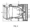
図4は、拡散器44の例示的な実施形態を概略的に示し、光、例えば光ガイド43によって案内され光ガイド突出部430を通って光ガイド43から出る光が、カプセル認識位置20に直接到達することを防止するために、拡散器44はその内側表面上に形成された突出要素440を備える。 FIG. 4 schematically shows an exemplary embodiment of a
図示した実施形態では、光ガイド44は、カプセル認識位置20に向かって半楕円体形の空洞開口部を形成しており、カメラ41は、好ましくは、カプセル認識位置41とは反対側の端部に配置されている。 In the illustrated embodiment, the
図示した実施形態では、突出要素440は、光ガイド43の光ガイド突出部430の先端を少なくとも部分的に覆っている。突出要素440の目的は、光ガイド突出部430の傾斜した先端部から拡散器44の長手方向軸に近い方向に屈折して出た光を遮断して、そのような光が直接、すなわち、拡散器44の内壁によって最初に少なくとも1回反射されることなく、カプセル認識位置20に到達することを回避することである。しかし、拡散器44の突出要素440は、好ましくは、拡散器44の内壁に向かって屈折された光が拡散器の空洞に入ることを可能にするように構成された開口部を備える。 In the illustrated embodiment, the projecting
任意選択的に、マシン1は、カプセル認識位置20に配置された又はカプセル認識位置に接近中のカプセルを検出するためのカプセル検出器を備える。カプセル検出器は、例えば、好ましくは電子基板42に取り付けられた、例えば電子基板42上に半田付けされたカプセル認識モジュール4内に含まれる。しかしながら、本発明の枠組み内で、カプセル検知器の他の位置への配置も可能である。カプセル検出器は、任意の適切な種類であってもよく、例えば、赤外線(IR)検出器、誘導性及び/又は抵抗性検出器、機械的スイッチング要素などの、存在及び/又は移動検出器であってもよい。カプセル検出器は、例えば、カプセル認識モジュール4のコントローラによって制御される、又はマシンの制御ユニットによって直接制御される。 Optionally, the
実施形態では、カプセルがカプセル認識位置20において、カプセルフィーダ2に接近中である時、及び/又はカプセルフィーダ2内に置かれた時、カプセル検出器はカプセルの存在を検出し、対応する信号をコントローラに及び/又はマシンの制御ユニットに送り、それにより、光源40が起動して、カプセル認識位置20に配置されたカプセルの表面の少なくとも一部を照らす。その結果、カメラ41が起動されて、照らされたカプセルの少なくとも一部の画像を取り込む。次いで、取り込まれたデジタル画像は、カプセルの種類を判定するために、ニューラルネットワーク演算装置に供給され、ニューラルネットワーク演算装置によって処置される。他の実施形態では、例えば、マシンがなんらかのカプセル検出器を備えていない場合、カプセル認識モジュール4、特に光源40及びカメラ41は、例えば飲料セレクタの起動によって、例えばマシンのユーザインターフェースのユーザ作動によって作動される。 In an embodiment, when a capsule is approaching and/or placed in the
好ましくは、カメラ41は、CCDセンサ、又はカプセルの少なくとも一部のデジタル画像、例えば、カラー画像又はグレースケール画像を提供する任意の適切なカメラである。画像は、入力データとしてニューラルネットワーク演算装置に供給され、ニューラルネットワーク演算装置は、カプセルの種類を判定するために、この入力データを使用してニューラルネットワークコンピュータプログラムを実行することになり、ニューラルネットワークのパラメータ、特にそのシナプス荷重及びバイアスは、ニューラルネットワークコンピュータプログラムによって実装された、ニューラルネットワークの訓練中に前もって設定されている。 Preferably, the
本発明による、カプセルの種類を判定するためのニューラルネットワークは、例えば、種々の種類のカプセルを1つ以上のカプセル認識位置に供給するためのカプセルフィーダを備える訓練ベンチ上で、手動で及び/又は自動的に訓練され、訓練ベンチのカプセル認識位置の各々は、供給された各カプセルの少なくとも一部の写真を、対応するカプセル認識位置において撮るためのカメラを備える。好ましくは、訓練ベンチのカプセル認識位置における電光及び画像取込み条件は、飲料調製マシン内のカプセル認識位置における条件と同様である。次いで、取り込まれた画像は、本発明のニューラルネットワークコンピュータプログラムを実行する演算装置への入力として供給される。各画像に対するプログラムの出力、すなわちニューラルネットワークの出力は、対応するサンプルカプセルの実際の種類と比較され、比較の結果はプログラムにフィードバックされ、プログラムは、ニューラルネットワークパラメータを、具体的には1つ以上のシナプス結合の荷重及び/又はバイアスを調整する。 The neural network for determining capsule type according to the present invention may be operated manually and/or, for example, on a training bench equipped with capsule feeders for feeding different types of capsules to one or more capsule recognition locations. Each of the automatically trained capsule recognition positions of the training bench is equipped with a camera for taking a photograph of at least a portion of each supplied capsule at the corresponding capsule recognition position. Preferably, the lighting and image capture conditions at the capsule recognition position in the training bench are similar to those at the capsule recognition position in the beverage preparation machine. The captured images are then provided as input to a computing device executing the neural network computer program of the present invention. The output of the program, i.e., the output of the neural network, for each image is compared with the actual type of corresponding sample capsule, and the results of the comparison are fed back to the program, which adjusts the neural network parameters, specifically one or more adjust the weights and/or biases of synaptic connections in
認識が成功する割合が所望の割合に達すると、ニューラルネットワークは好ましくは十分に訓練されたと考えられ、調整されたパラメータを有するニューラルネットワークプログラムは、例えば、コピーされ、本発明の飲料調製マシンに組み込まれた又は組み込まれることになるニューラルネットワーク演算装置に読み込まれてもよい。 Once the desired percentage of successful recognitions has been reached, the neural network is preferably considered sufficiently trained, and the neural network program with adjusted parameters can, for example, be copied and incorporated into the beverage preparation machine of the present invention. may be loaded into a neural network computing device that is or will be incorporated.
本発明のニューラルネットワークコンピュータプログラムは、新しい種類のカプセルを含むカプセルを用いた、上述のスキームに従う新しい訓練セッションによって、新しい種類のカプセルを認識するように更新されてもよい。いったん新しい種類のカプセルがニューラルネットワークによって学習されると、更新されたパラメータを有するコンピュータプログラムがコピーされ、機能マシン(functional machines)のニューラルネットワーク演算装置に読み込まれて、そのカプセル認識モジュールが新しいバージョンに更新されてもよい。任意選択的に、様々な認識されたカプセルの種類のうちの1つのカプセルの種類は、マシンにとって未知のカプセルに対応する。 The neural network computer program of the present invention may be updated to recognize new types of capsules by new training sessions according to the above scheme with capsules containing new types of capsules. Once a new type of capsule has been learned by the neural network, the computer program with the updated parameters is copied and loaded into the neural network arithmetic units of the functional machines to update the capsule recognition module to the new version. May be updated. Optionally, one capsule type of the various recognized capsule types corresponds to a capsule unknown to the machine.
本発明のニューラルネットワークコンピュータプログラムの訓練は、好ましくは、飲料調製マシンの外部にある訓練ベンチ上で実施される。しかし、サンプルカプセルの画像を取り込む条件は、好ましくは、マシン内の条件と類似している又は同一でさえある。 Training of the neural network computer program of the present invention is preferably performed on a training bench external to the beverage preparation machine. However, the conditions for capturing the image of the sample capsule are preferably similar or even identical to the conditions in the machine.
本発明のニューラルネットワークコンピュータプログラムによって実装されるニューラルネットワークについての好適なアーキテクチャの一例を、以下の表に要約する。
この実施例によれば、ニューラルネットワークは、12の層を含む畳み込みニューラルネットワークであり、第1の畳み込み層は、128×128×1の入力サイズを有する。したがって、ニューラルネットワークは、典型的には、128画素×128画素のグレースケール画像をその入力として予想し、11重の分類を実行する。ニューラルネットワークは、例えば、5層の基本層、すなわち、3層の畳み込み層、及びそれに続く2層の全結合層を含む。全ての畳み込み層はサイズ3×3×1のカーネルを使用し、ストライドは1であり、パディングは実施せず、32の出力特徴マップが生成される。畳み込みの各々の後に、ReLUの非線形、及び最大プーリング、サブサンプリング演算が続く。次いで、特徴抽出部の出力は、2層の全結合された分類器、例えばLogSoftMax分類器に供給される。分類器の隠れ層は、例えば64個のニューロンから構築され、ReLU活性化関数も同様に使用される。 According to this example, the neural network is a convolutional neural network comprising 12 layers, the first convolutional layer having an input size of 128x128x1. Therefore, a neural network typically expects a 128 pixel by 128 pixel grayscale image as its input and performs 11-fold classification. A neural network, for example, includes 5 base layers: 3 convolutional layers followed by 2 fully connected layers. All convolutional layers use kernels of size 3x3x1, stride is 1, and no padding is performed, yielding 32 output feature maps. Each convolution is followed by ReLU's non-linear and max pooling, sub-sampling operations. The output of the feature extractor is then fed to a two-layer fully-connected classifier, such as the LogSoftMax classifier. The hidden layer of the classifier is constructed from eg 64 neurons and the ReLU activation function is used as well.
好ましくは、画像データ入力が本発明のニューラルネットワークを介して送られる前に、データに3ステップの前処理が実施される。第1の前処理ステップでは、データは、好ましくは、各画素について訓練セット全体にわたって計算された平均活性化(mean activation)を減算することにより、ゼロを中心とした分布になる。第2の前処理ステップでは、データは、入力値の範囲を正規化するために、データセットのグローバル標準偏差によって除算される。第3及び最後の前処理ステップでは、ピクチャ内のエッジを増幅するために、13×13ガウス重み付けウィンドウ(Gaussian weighting window)を用いて局所コントラスト正規化を行う。 Preferably, before the image data input is sent through the neural network of the present invention, three steps of preprocessing are performed on the data. In a first preprocessing step, the data are preferably zero-centered by subtracting the mean activation computed over the entire training set for each pixel. In a second preprocessing step, the data are divided by the global standard deviation of the dataset to normalize the range of input values. The third and final preprocessing step performs local contrast normalization with a 13×13 Gaussian weighting window to amplify the edges in the picture.
しかし、カプセルのデジタル画像又はその少なくとも一部に基づいて、カプセルの種類の認識を信頼性高く実現するために、他のニューラルネットワークアーキテクチャ及び/又はデータ前処理が本発明の枠組み内で可能である。 However, other neural network architectures and/or data pre-processing are possible within the framework of the present invention in order to reliably achieve capsule type recognition based on a digital image of the capsule or at least part thereof. .
Claims (7)
Translated fromJapanese飲料原材料カプセルに対して抽出を行い前記飲料を形成するための抽出ユニットであって、例えば、第1の部分及び第2の部分を有し、前記第1の部分及び前記第2の部分が、カプセルを挿入及び/又は除去するための離隔位置と、前記第1の部分及び前記第2の部分が抽出チャンバを画定する閉位置のような、前記カプセルを固定して抽出を行うための閉位置との間で相対的に移動可能であり、任意選択的に、前記部分のうちの少なくとも1つがカプセルオープナー、例えば1つ以上のカプセル穴開け器を有し、かつ/又は前記部分のうちの少なくとも1つが、前記カプセルに収容された原材料と混合される液体を流入させるための開口部を有する、抽出ユニットと、
前記カプセルに対して抽出を行うために前記抽出ユニットを制御するための制御ユニットであって、例えば、電気コードを介して、電源によって給電される、制御ユニットと、
前記カプセルに対して抽出を行うことによって形成された前記飲料を、ユーザ容器であって、容器支持体、例えば前記マシンが配置されている外部配置支持体上の容器配置領域、又はマシン支持体、例えば移動可能若しくは取り外し可能なマシン支持体上の容器配置領域に配置されて前記飲料を収集するための、カップ又はマグなどの、ユーザ容器に注出するための出口と、
前記マシン内に挿入されたカプセルをカプセル認識位置において認識するためのカプセル認識モジュールであって、前記カプセル認識位置にある前記カプセルの少なくとも一部の画像を取り込むためのカメラを備える、カプセル認識モジュールと、
前記カプセル認識位置においてカプセルを照らすための少なくとも1つの光源、例えば少なくとも1つのLEDと、を備え、
前記カプセル認識モジュールが、前記少なくとも1つの光源の光を前記カプセル認識位置に向けて拡散させるための拡散器を備える、マシンにおいて、
前記マシンは、前記少なくとも1つの光源から前記拡散器へと光を案内するための光ガイドを更に備え、
前記光ガイドは、前記少なくとも1つの光源から前記拡散器へと光を案内するための少なくとも1つの光ガイド突出部を備え、
前記拡散器は、前記少なくとも1つの光ガイド突出部から出て前記拡散器に導かれた光を前記カプセル認識位置に向けて拡散させるように配置されていることを特徴とする、マシン。A machine for preparing and dispensing beverages such as tea, coffee, hot chocolate, cold chocolate, milk, soup or baby food, comprising:
A brewing unit for brewing a beverage ingredient capsule to form said beverage, for example comprising a first portion and a second portion, said first portion and said second portion comprising: a closed position for fixing said capsule and for brewing, such as a spaced position for inserting and/or removing a capsule and a closed position wherein said first portion and said second portion define a brewing chamber. optionally at least one of said parts comprises a capsule opener, e.g. one or more capsule punches, and/or at least one of said parts a brewing unit, one of which has an opening for admitting a liquid to be mixed with the ingredients contained in the capsule;
a control unit for controlling the brewing unit to perform brewing on the capsule, the control unit being powered by a power supply, e.g. via an electrical cord;
placing the beverage formed by brewing on the capsule in a user container, a container support, such as a container placement area on an externally located support on which the machine is placed, or a machine support; an outlet for dispensing into a user container, such as a cup or mug, for example positioned in a container placement area on a movable or removable machine support to collect said beverage;
a capsule recognition module for recognizing a capsule inserted into the machine at a capsule recognition position, the capsule recognition module comprising a camera for capturing an image of at least a portion of the capsule at the capsule recognition position; ,
at least one light source, such as at least one LED, for illuminating the capsule at the capsule recognition position;
A machine, wherein the capsule recognitionmodule comprises a diffuser for diffusing the light of the at least one light source towards the capsule recognition position,
the machine further comprising a light guide for guiding light from the at least one light source to the diffuser;
the light guide comprises at least one light guide protrusion for guiding light from the at least one light source to the diffuser;
The machine of claim 1, wherein the diffuser is arranged to diffuse light directed to the diffuser from the at least one light guide projection toward the capsule recognition location.
Applications Claiming Priority (3)
| Application Number | Priority Date | Filing Date | Title |
|---|---|---|---|
| EP18156197 | 2018-02-09 | ||
| EP18156197.8 | 2018-02-09 | ||
| PCT/EP2018/065935WO2019154526A1 (en) | 2018-02-09 | 2018-06-15 | Beverage preparation machine with capsule recognition |
Publications (2)
| Publication Number | Publication Date |
|---|---|
| JP2021512677A JP2021512677A (en) | 2021-05-20 |
| JP7242686B2true JP7242686B2 (en) | 2023-03-20 |
Family
ID=61192746
Family Applications (3)
| Application Number | Title | Priority Date | Filing Date |
|---|---|---|---|
| JP2020541561AActiveJP7242686B2 (en) | 2018-02-09 | 2018-06-15 | Beverage preparation machine that recognizes capsules |
| JP2020541504AActiveJP7486425B2 (en) | 2018-02-09 | 2018-06-15 | Capsule-recognizing beverage preparation machine |
| JP2024014732APendingJP2024042068A (en) | 2018-02-09 | 2024-02-02 | Beverage preparation machine that recognizes capsules |
Family Applications After (2)
| Application Number | Title | Priority Date | Filing Date |
|---|---|---|---|
| JP2020541504AActiveJP7486425B2 (en) | 2018-02-09 | 2018-06-15 | Capsule-recognizing beverage preparation machine |
| JP2024014732APendingJP2024042068A (en) | 2018-02-09 | 2024-02-02 | Beverage preparation machine that recognizes capsules |
Country Status (13)
| Country | Link |
|---|---|
| US (4) | US12329310B2 (en) |
| EP (4) | EP4505916A3 (en) |
| JP (3) | JP7242686B2 (en) |
| CN (2) | CN111655093B (en) |
| AU (3) | AU2018408336B2 (en) |
| CA (2) | CA3089664A1 (en) |
| ES (1) | ES3010373T3 (en) |
| FI (1) | FI3749153T3 (en) |
| HU (1) | HUE070758T2 (en) |
| PL (1) | PL3749153T3 (en) |
| PT (1) | PT3749153T (en) |
| RU (1) | RU2769354C2 (en) |
| WO (2) | WO2019154527A1 (en) |
Families Citing this family (25)
| Publication number | Priority date | Publication date | Assignee | Title |
|---|---|---|---|---|
| CN110754946B (en)* | 2019-11-20 | 2024-09-27 | 宁波霍科电器有限公司 | Milk brewing machine |
| ES2975752T3 (en)* | 2020-02-05 | 2024-07-12 | Nestle Sa | Capsule recognition beverage preparation machine |
| US12213617B2 (en) | 2022-05-13 | 2025-02-04 | Sharkninja Operating Llc | Flavored beverage carbonation process |
| US11647860B1 (en) | 2022-05-13 | 2023-05-16 | Sharkninja Operating Llc | Flavored beverage carbonation system |
| US12096880B2 (en) | 2022-05-13 | 2024-09-24 | Sharkninja Operating Llc | Flavorant for beverage carbonation system |
| US11751585B1 (en) | 2022-05-13 | 2023-09-12 | Sharkninja Operating Llc | Flavored beverage carbonation system |
| AU2022457789A1 (en) | 2022-05-13 | 2024-11-21 | Sharkninja Operating Llc | Agitator for a carbonation system |
| IT202200015462A1 (en) | 2022-07-22 | 2024-01-22 | Lavazza Luigi Spa | Control system and procedure for a machine for the preparation and dispensing of hot drinks by controlled infusion of a precursor substance in granular or powder form, based on the recognition and classification of a dosing unit inserted into the machine |
| IT202200015474A1 (en) | 2022-07-22 | 2024-01-22 | Lavazza Luigi Spa | Tablet for the extraction of a beverage and the process for its production |
| WO2024023357A1 (en)* | 2022-07-29 | 2024-02-01 | Société des Produits Nestlé S.A. | Beverage or foodstuff preparation system |
| US12005404B2 (en) | 2022-08-22 | 2024-06-11 | Sharkninja Operating Llc | Beverage carbonation system flow control |
| CN115500715A (en)* | 2022-09-23 | 2022-12-23 | 广州大学 | Intelligent seasoning adding control system |
| US11745996B1 (en) | 2022-11-17 | 2023-09-05 | Sharkninja Operating Llc | Ingredient containers for use with beverage dispensers |
| US12103840B2 (en) | 2022-11-17 | 2024-10-01 | Sharkninja Operating Llc | Ingredient container with sealing valve |
| US12084334B2 (en) | 2022-11-17 | 2024-09-10 | Sharkninja Operating Llc | Ingredient container |
| US11634314B1 (en) | 2022-11-17 | 2023-04-25 | Sharkninja Operating Llc | Dosing accuracy |
| US11738988B1 (en) | 2022-11-17 | 2023-08-29 | Sharkninja Operating Llc | Ingredient container valve control |
| USD1092208S1 (en) | 2022-12-23 | 2025-09-09 | Sharkninja Operating Llc | Cap of ingredient container |
| USD1091308S1 (en) | 2022-12-23 | 2025-09-02 | Sharkninja Operating Llc | Ingredient container |
| US12116257B1 (en) | 2023-03-22 | 2024-10-15 | Sharkninja Operating Llc | Adapter for beverage dispenser |
| US11871867B1 (en) | 2023-03-22 | 2024-01-16 | Sharkninja Operating Llc | Additive container with bottom cover |
| US11925287B1 (en) | 2023-03-22 | 2024-03-12 | Sharkninja Operating Llc | Additive container with inlet tube |
| US12005408B1 (en) | 2023-04-14 | 2024-06-11 | Sharkninja Operating Llc | Mixing funnel |
| US12369744B1 (en) | 2024-01-18 | 2025-07-29 | Sharkninja Operating Llc | Preparation of beverage machines for cold beverage brewing |
| WO2025155323A1 (en) | 2024-01-18 | 2025-07-24 | Sharkninja Operating Llc | Preventing coffee bean grinder jamming |
Citations (3)
| Publication number | Priority date | Publication date | Assignee | Title |
|---|---|---|---|---|
| JP2009512957A (en) | 2005-10-24 | 2009-03-26 | コグネックス テクノロジー アンド インベストメント コーポレイション | Built-in lighting assembly for symbolology reader |
| JP2014511712A (en) | 2011-03-14 | 2014-05-19 | ネステク ソシエテ アノニム | Automatic beverage machine |
| JP2017536895A (en) | 2014-12-01 | 2017-12-14 | キュー・ビー・オー・コーヒー・ゲゼルシャフト・ミット・ベシュレンクテル・ハフツングQbo Coffee Gmbh | Brewing module, capsule recognition module, and beverage preparation machine |
Family Cites Families (141)
| Publication number | Priority date | Publication date | Assignee | Title |
|---|---|---|---|---|
| CH605293A5 (en) | 1976-12-17 | 1978-09-29 | Nestle Sa | |
| US4377049A (en) | 1980-05-22 | 1983-03-22 | Pepsico Inc. | Capacitive switching panel |
| US4458735A (en) | 1982-09-30 | 1984-07-10 | Medetec Industries, Inc. | Dispensing arrangement for a beverage such as a milkshake |
| US4554419A (en) | 1983-12-02 | 1985-11-19 | The Coca-Cola Company | Touch selection panel for a vending machine |
| JPS6282496A (en) | 1985-10-05 | 1987-04-15 | サンデン株式会社 | Self-service store apparatus |
| DE3615158C2 (en) | 1986-05-05 | 1990-11-15 | Cafina Ag | Method for preparing a plurality of coffee portions |
| FR2624844B1 (en) | 1987-12-18 | 1990-07-20 | Andries Eric | APPARATUS FOR MAKING BEVERAGES MADE OF MIXTURES OF INGREDIENTS, ESPECIALLY COCKTAILS |
| JP2961621B2 (en) | 1990-09-27 | 1999-10-12 | 豊田工機株式会社 | Learning method of machining condition creation function of numerical controller |
| TW199884B (en) | 1991-05-08 | 1993-02-11 | Sociere Des Produits Nestle S A | |
| US5161455A (en) | 1991-05-15 | 1992-11-10 | Bunn-O-Matic Corporation | Combination coffee and tea brewer |
| JP2960590B2 (en) | 1991-09-27 | 1999-10-06 | 東芝機械株式会社 | Automatic dispensing device for sparkling beverages |
| DE4137324C1 (en) | 1991-11-13 | 1993-02-04 | Cis Elektrogeraete Ag, Hinwil, Ch | |
| CH682798A5 (en) | 1991-11-15 | 1993-11-30 | Salvis Ag | Coffee machine with grinder, brewer and dispenser in one unit - has all three modules in one structure, behind front and each is accessible from top or front, brewing module has two brewing stations |
| IT1252633B (en) | 1991-12-05 | 1995-06-19 | Gianmauro Zani | COMPACT COFFEE MACHINE FOR ESPRESSO COFFEE AND HOT WATER FALL COFFEE FOR FILTRATION OTHERWISE KNOWN AS AMERICAN COFFEE. |
| US5731981A (en) | 1992-06-08 | 1998-03-24 | Azbar, Inc. | Beverage dispensing system for bar |
| US5372061A (en) | 1993-04-14 | 1994-12-13 | Avanti Espresso U.S.A., Inc. | Espresso/cappuccino apparatus and method |
| JP3153412B2 (en)* | 1994-04-01 | 2001-04-09 | 旭光学工業株式会社 | Data symbol reading device |
| US5353692A (en) | 1993-09-29 | 1994-10-11 | Unidynamics Corporation | Hot beverage brewing apparatus |
| US5375508A (en) | 1993-12-29 | 1994-12-27 | Bunn-O-Matic Corporation | Digital brewer control |
| US5744793A (en) | 1994-02-28 | 1998-04-28 | Electro-Pro, Inc. | Triangulation position-detection and integrated dispensing valve |
| DE4429353A1 (en) | 1994-08-19 | 1996-02-22 | Joachim Koeninger | Universal automatic drinks dispenser |
| IT1280833B1 (en) | 1995-03-31 | 1998-02-11 | Enrico Marogna | DEVICE FOR CONTROL OF COFFEE GRINDING, GRINDER DOSING MACHINE EQUIPPED WITH THIS DEVICE AND PROCEDURE FOR THE |
| US5685435A (en) | 1995-05-08 | 1997-11-11 | Mars Incorporated | Method and apparatus for automatic bulk vending |
| JPH1028647A (en)* | 1996-07-17 | 1998-02-03 | Matsushita Electric Ind Co Ltd | Cooker |
| US5959869A (en) | 1996-12-03 | 1999-09-28 | The Coca-Cola Company | Vending machine controller and system |
| US5836236A (en) | 1997-03-03 | 1998-11-17 | Rolfes; Patrick J. | Coffee brewer and hot water dispenser |
| US6082419A (en) | 1998-04-01 | 2000-07-04 | Electro-Pro, Inc. | Control method and apparatus to detect the presence of a first object and monitor a relative position of the first or subsequent objects such as container identification and product fill control |
| US6601768B2 (en)* | 2001-03-08 | 2003-08-05 | Welch Allyn Data Collection, Inc. | Imaging module for optical reader comprising refractive diffuser |
| AT410377B (en) | 1998-07-27 | 2003-04-25 | Dosy Star Electronics Vertrieb | DRINKS OUTPUT DEVICE |
| US6182555B1 (en) | 1999-04-07 | 2001-02-06 | Red River Tea Company | Apparatus and methods for brewing and dispensing beverages |
| US6759072B1 (en) | 1999-08-14 | 2004-07-06 | The Procter + Gamble Co. | Methods and systems for utilizing delayed dilution, mixing and filtration for providing customized beverages on demand |
| PT1090574E (en) | 1999-08-31 | 2005-02-28 | Nestle Sa | DEVICE FOR EXTRACTION OF A SUBSTANCE FOR THE PREPARATION OF A DRINK |
| US6354341B1 (en) | 1999-11-10 | 2002-03-12 | Shurflo Pump Manufacturing Co., Inc. | Rapid comestible fluid dispensing apparatus and method |
| US6459854B1 (en) | 2000-01-24 | 2002-10-01 | Nestec S.A. | Process and module for heating liquid |
| ATE274321T1 (en) | 2000-11-28 | 2004-09-15 | Nestle Sa | PERCOLATION DEVICE |
| DE10154046A1 (en) | 2001-11-02 | 2003-05-22 | Miele & Cie | household appliance |
| DE20200419U1 (en) | 2002-01-12 | 2002-05-29 | Wik Far East Ltd., North Point | Electrical household or personal care device that is stationary during operation |
| DK1808382T3 (en) | 2002-01-16 | 2013-03-25 | Nestle Sa | Closed capsule with a beaker with opening means |
| DE60227248D1 (en) | 2002-07-12 | 2008-08-07 | Nestec Sa | Device for heating a liquid |
| WO2004030435A2 (en) | 2002-10-02 | 2004-04-15 | Automated Beverage Technologies Ltd | Dispenser |
| WO2004030438A2 (en) | 2002-10-04 | 2004-04-15 | Lancer Partnership, Ltd. | Multiple brand ice beverage dispenser |
| GB2397503B (en) | 2003-01-24 | 2005-03-02 | Kraft Foods R & D Inc | Machine for the preparation of beverages |
| GB2397510A (en) | 2003-01-24 | 2004-07-28 | Kraft Foods R & D Inc | Cartridge and machine for the preparation of beverages |
| EP1495702A1 (en) | 2003-07-10 | 2005-01-12 | Nestec S.A. | Device for the extraction of a cartridge |
| TW581668B (en)* | 2003-10-15 | 2004-04-01 | Der-Yang Tien | Endoscopic device |
| EP1681968B1 (en) | 2003-11-07 | 2013-04-17 | Bunn-O-Matic Corporation | Adjustable volume brewer |
| EP1744812B2 (en)* | 2004-05-03 | 2014-06-04 | Woodwelding AG | Light diffuser and process for producing the same |
| EP1634520A1 (en) | 2004-09-13 | 2006-03-15 | Nestec S.A. | Device and method for heating a liquid |
| DE602004031632D1 (en) | 2004-11-11 | 2011-04-14 | Nestec Sa | Self-cleaning mixing head for milk drinks and machines with such a mixing head |
| CA2590304C (en) | 2004-12-14 | 2014-06-10 | Nestec S.A. | Device and method for controlling the filling of a cup in a drinks vending machine such as a coffee machine |
| US9292724B1 (en)* | 2004-12-16 | 2016-03-22 | Cognex Corporation | Hand held symbology reader illumination diffuser with aimer optics |
| EP1676509A1 (en) | 2004-12-30 | 2006-07-05 | Rhea Vendors S.p.A. | Process and apparatus for controlling the preparation of brewed beverages |
| JP2008531162A (en) | 2005-02-28 | 2008-08-14 | コーヒー ネーション リミテッド | Equipment for producing beverages |
| DE602005007475D1 (en) | 2005-06-07 | 2008-07-24 | Nestec Sa | Beverage machine with drip tray for containers of different heights |
| CH697974B1 (en) | 2005-07-01 | 2009-04-15 | Saeco Ipr Ltd | Operating device for hot beverage vending machines. |
| EP1899927A1 (en) | 2005-07-01 | 2008-03-19 | Saeco IPR Limited | Operator's device for automatic hot beverage dispensers |
| PT1767129E (en) | 2005-09-27 | 2008-11-11 | Nestec Sa | Extraction module for a capsule-based beverage production device |
| US8061610B2 (en)* | 2005-10-24 | 2011-11-22 | Cognex Technology And Investment Corporation | System and method for employing color illumination and color filtration in a symbology reader |
| DE202006019039U1 (en) | 2005-12-19 | 2007-03-08 | Mayer, Martin | Drinks dispenser especially for water also has information display formed by flat screen with liquid crystals, diodes or plasma unit to provide information and advertising |
| EP1859714B2 (en) | 2006-05-24 | 2015-05-27 | Nestec S.A. | Brewing device and brewing capsule system with a capsule holder for facilitating insertion and removal of capsules |
| DE602006009232D1 (en) | 2006-05-24 | 2009-10-29 | Nestec Sa | Brewing device for capsule with locking mechanism with variable transmission ratio |
| ES2415132T3 (en) | 2006-06-16 | 2013-07-24 | Nestec S.A. | Beverage distribution device with a support and drop recovery system for containers of different sizes |
| AU2007302077A1 (en) | 2006-09-26 | 2008-04-03 | Nestec S.A. | Extraction system for the preparation of a beverage from a cartridge |
| DE102007008590A1 (en) | 2007-02-16 | 2008-08-21 | Siemens Ag | Encapsulation housing arrangement for use in electric power transmission arrangement, has cooling element i.e. collar, circulated about rotational axis, and aligned coaxially to rotational axis in region of shell surface |
| GB2447024A (en) | 2007-02-27 | 2008-09-03 | Kraft Foods R & D Inc | A dispensing machine for hot or cold drinks |
| PL2162653T3 (en) | 2007-05-16 | 2011-11-30 | Nestec Sa | Control device having a peristaltic valve for a drink preparing machine |
| EP1992263B2 (en) | 2007-05-16 | 2016-10-12 | Nestec S.A. | Beverage production module and method for operating a beverage production module |
| EP2218369B1 (en) | 2007-10-04 | 2017-05-03 | Nestec S.A. | Beverage brewing unit |
| EP2070454B1 (en) | 2007-12-12 | 2015-07-15 | Nestec S.A. | Beverage production machines comprising a plurality of core units |
| AU2008334691B2 (en) | 2007-12-12 | 2015-01-22 | Société des Produits Nestlé S.A. | Used capsule or pod receptacle for liquid food or beverage machines |
| EP2085000B2 (en) | 2008-01-29 | 2020-03-04 | Koninklijke Douwe Egberts B.V. | Coffee brewer and a corresponding network-based method and apparatus |
| DK2276380T3 (en) | 2008-05-07 | 2013-09-08 | Nestec Sa | Capsule collector for used capsules for home appliances |
| EP2296515B1 (en) | 2008-05-28 | 2012-07-18 | Nestec S.A. | Pump for liquid beverage preparation devices |
| EP2299851B1 (en)* | 2008-07-08 | 2018-08-22 | Nestec S.A. | Portion-controlled nutrition system and method using capsules |
| AU2009268073B2 (en) | 2008-07-09 | 2014-12-04 | Nestec S.A. | Ergonomic interface screen for a beverage machine |
| EP2309900B1 (en) | 2008-08-08 | 2015-05-27 | Nestec S.A. | Beverage machine with carrying handle and configurable appearance&side functions |
| US20110168026A1 (en) | 2008-10-03 | 2011-07-14 | Nestec S.A. | User friendly interface for a beverage machine |
| EP2228633B1 (en)* | 2009-03-10 | 2017-07-05 | Nestec S.A. | Optical level detector for a beverage machine |
| WO2010108700A1 (en) | 2009-03-23 | 2010-09-30 | Nestec S.A. | Pump mount in a beverage preparation machine |
| EP2427085B1 (en) | 2009-05-06 | 2016-09-21 | Nestec S.A. | Method for manufacturing beverage machines with simplified servicing |
| US8973488B2 (en) | 2009-10-05 | 2015-03-10 | Nestec S.A. | Cartridge extraction device |
| BR112012007816A2 (en) | 2009-10-05 | 2016-08-30 | Nestec Sa | ergonomic capsule extraction device |
| BR112012011161A8 (en) | 2009-11-12 | 2019-02-12 | Formulanow Llc | punching, cartridge and mixing equipment and method for combining mixing and liquid |
| BR112012017591A2 (en) | 2010-01-15 | 2016-08-16 | Nestec Sa | ergonomic service unit for beverage preparation machines |
| JP2013517026A (en) | 2010-01-15 | 2013-05-16 | ネステク ソシエテ アノニム | Cooperation between ergonomic raw material holder and service unit |
| EP2345352A1 (en)* | 2010-01-19 | 2011-07-20 | Nestec S.A. | Method for providing information to a user from a capsule for the preparation of a beverage using a code |
| RU2560323C2 (en) | 2010-03-05 | 2015-08-20 | Нестек С.А. | Pump with reduced vibration |
| EP2572609B1 (en)* | 2010-05-20 | 2019-01-09 | Teatek Co., Ltd | Drink material cup, identification device, drink preparation machine, drink preparation system and drink preparation method |
| WO2011144719A1 (en) | 2010-05-21 | 2011-11-24 | Nestec S.A. | Ergonomic handle & user-interface |
| BR112012029661B1 (en) | 2010-05-21 | 2020-01-28 | Nestec Sa | machine to prepare a drink |
| WO2011144212A1 (en)* | 2010-05-21 | 2011-11-24 | Chemometec A/S | A compact dark field light source and dark field image analysis at low magnification |
| CA2801278A1 (en) | 2010-06-09 | 2011-12-15 | Nestec S.A. | Ergonomic service arrangement for beverage machine |
| JP2013535242A (en) | 2010-07-12 | 2013-09-12 | ネステク ソシエテ アノニム | Secure cup support for beverage machines |
| EP2608704B1 (en) | 2010-08-27 | 2016-06-22 | Nestec S.A. | Simple motorized brewing unit |
| CN103188972B (en) | 2010-09-07 | 2015-08-05 | 雀巢产品技术援助有限公司 | Ergonomic handle with user interface |
| EP2446789A1 (en)* | 2010-10-27 | 2012-05-02 | Koninklijke Philips Electronics N.V. | Tea maker with luminous brewing progress indicator |
| EP2645914B1 (en) | 2010-12-01 | 2016-07-13 | Nestec S.A. | Beverage preparation machine with drop collector |
| MX2013007768A (en) | 2011-01-03 | 2013-11-20 | Nestec Sa | Beverage machine with a cover for an ingredient inlet. |
| EP2668612B1 (en) | 2011-01-24 | 2016-01-20 | Datalogic ADC, Inc. | Tunnel or portal scanner and method of scanning for automated checkout |
| JP6223339B2 (en) | 2011-08-25 | 2017-11-01 | ネステク ソシエテ アノニム | Cartridge alignment system |
| BR112014003976A2 (en) | 2011-08-25 | 2017-03-07 | Nestec Sa | cartridge chamber of an extraction system |
| ES2546531T3 (en) | 2011-12-30 | 2015-09-24 | Nestec S.A. | A machine for drinks with multiple systems |
| EP2633789A1 (en) | 2012-02-28 | 2013-09-04 | Nestec S.A. | Beverage preparation machine with drop management |
| JP2015507993A (en) | 2012-02-28 | 2015-03-16 | ネステク ソシエテ アノニム | Cover for raw material inlet with humidity control |
| DE112012001531T5 (en) | 2012-02-28 | 2013-12-24 | Nestec S.A. | Capsule-controlled motorized brewing unit |
| CA2874954A1 (en) | 2012-06-15 | 2013-12-19 | Nestec S.A. | Beverage machine with vibration inhibitor |
| EP2892401B1 (en) | 2012-09-07 | 2016-10-26 | Nestec S.A. | Capsule storage |
| AU2013311704A1 (en) | 2012-09-07 | 2015-03-05 | Nestec S.A. | Capsule storage |
| JP2015534486A (en) | 2012-10-09 | 2015-12-03 | ネステク ソシエテ アノニム | Beverage machine equipped with ingredient capsule attachment device |
| US10092130B2 (en) | 2012-11-12 | 2018-10-09 | Nestec S.A. | Opener for making large openings in capsules |
| WO2014095985A1 (en)* | 2012-12-21 | 2014-06-26 | Nestec S.A. | Beverage production system |
| RU2015145283A (en) | 2013-03-22 | 2017-04-26 | Нестек С.А. | CAPSULE WITH CODE AND AUTOMATIC BEVERAGE SYSTEM |
| ITTO20130567A1 (en)* | 2013-07-08 | 2015-01-09 | Lavazza Luigi Spa | MACHINE AND SYSTEM FOR THE PREPARATION OF LIQUID PRODUCTS VIA CAPSULES |
| CN105636488A (en)* | 2013-10-18 | 2016-06-01 | K-Fee系统股份有限公司 | System and method for preparing a beverage |
| US9474406B2 (en)* | 2014-01-17 | 2016-10-25 | Keurig Green Mountain, Inc. | Apparatus with beverage cartridge holder having movable outlet |
| EP3129896B1 (en)* | 2014-04-09 | 2024-02-14 | Entrupy Inc. | Authenticating physical objects using machine learning from microscopic variations |
| WO2015173285A1 (en) | 2014-05-13 | 2015-11-19 | Nestec S.A. | Container and code of system for preparing a beverage or foodstuff |
| EP3143552B8 (en)* | 2014-05-13 | 2021-08-04 | Société des Produits Nestlé S.A. | Container and code of system for preparing a beverage or foodstuff |
| PL3143554T3 (en) | 2014-05-13 | 2021-11-02 | Société des Produits Nestlé S.A. | Container and code of system for preparing a beverage or foodstuff |
| ES2699086T3 (en) | 2014-07-09 | 2019-02-07 | Nestec Sa | Accessory to automatically supply a beverage machine with a liquid from a distribution network |
| CN106470578B (en) | 2014-07-09 | 2020-02-28 | 雀巢产品有限公司 | Capsule handling unit for beverage preparation machines |
| WO2016005417A1 (en) | 2014-07-09 | 2016-01-14 | Nestec S.A. | Capsule processing unit of beverage preparation machine |
| KR20170078809A (en)* | 2014-11-07 | 2017-07-07 | 쓰리엠 이노베이티브 프로퍼티즈 컴파니 | Lighting component including switchable diffuser |
| US11684204B2 (en) | 2014-11-27 | 2023-06-27 | Societe Des Produits Nestle S.A. | Liquid dispensing machine with compact drop stop |
| CN107105930B (en) | 2014-12-18 | 2021-09-07 | 雀巢产品有限公司 | Removable cup support platform on collector receiver |
| PT3232877T (en) | 2014-12-18 | 2020-04-23 | Nestle Sa | Beverage machine with self-positioning cup-support |
| AU2015366401B2 (en) | 2014-12-18 | 2019-12-12 | Société des Produits Nestlé S.A. | Beverage machine with slidingly connectable cup-support |
| US10683971B2 (en)* | 2015-04-30 | 2020-06-16 | Cree, Inc. | Solid state lighting components |
| EP3292738B1 (en) | 2015-05-05 | 2020-12-30 | June Life, Inc. | A connected oven |
| US10614339B2 (en) | 2015-07-29 | 2020-04-07 | Nokia Technologies Oy | Object detection with neural network |
| CA2995147C (en) | 2015-09-04 | 2023-12-12 | Nestec S.A. | Beverage machine with ergonomic outlet |
| JP6910344B2 (en) | 2015-09-04 | 2021-07-28 | ソシエテ・デ・プロデュイ・ネスレ・エス・アー | Beverage machine with ergonomic user interface |
| JP2017097585A (en)* | 2015-11-24 | 2017-06-01 | 株式会社リコー | Learning apparatus, program, and learning method |
| EP3175745A1 (en)* | 2015-12-01 | 2017-06-07 | Qbo Coffee GmbH | Brewing module, capsule sensor module and machine for making beverages |
| US9784497B2 (en) | 2016-02-03 | 2017-10-10 | Multimedia Image Solution Limited | Smart refrigerator |
| JP6674277B2 (en)* | 2016-02-24 | 2020-04-01 | オリンパス株式会社 | Lighting adapter |
| KR102598711B1 (en)* | 2016-07-07 | 2023-11-06 | 삼성전자주식회사 | lidar apparatus emitting non-uniform light and autonomous robot comprising thereof |
| EP3275345B2 (en) | 2016-07-25 | 2023-02-22 | Société des Produits Nestlé S.A. | Machine and electronic device for personalized beverage preparation |
| CN106778912A (en)* | 2017-01-13 | 2017-05-31 | 湖南理工学院 | A kind of full-automatic apparatus for baking and method for cake |
| CN107595102B (en)* | 2017-09-28 | 2020-08-11 | 珠海格力电器股份有限公司 | Control method, device and system of cooking appliance, storage medium and processor |
| CN107977456B (en)* | 2017-12-15 | 2018-10-30 | 清华大学 | A kind of multi-source big data analysis method based on multitask depth network |
- 2018
- 2018-06-15JPJP2020541561Apatent/JP7242686B2/enactiveActive
- 2018-06-15USUS16/968,438patent/US12329310B2/enactiveActive
- 2018-06-15USUS16/968,434patent/US11957270B2/enactiveActive
- 2018-06-15EPEP24214563.9Apatent/EP4505916A3/enactivePending
- 2018-06-15RURU2020129181Apatent/RU2769354C2/enactive
- 2018-06-15PLPL18730361.5Tpatent/PL3749153T3/enunknown
- 2018-06-15CNCN201880087426.1Apatent/CN111655093B/enactiveActive
- 2018-06-15ESES18730361Tpatent/ES3010373T3/enactiveActive
- 2018-06-15AUAU2018408336Apatent/AU2018408336B2/enactiveActive
- 2018-06-15WOPCT/EP2018/065939patent/WO2019154527A1/ennot_activeCeased
- 2018-06-15CACA3089664Apatent/CA3089664A1/enactivePending
- 2018-06-15CNCN201880087370.XApatent/CN111629637A/enactivePending
- 2018-06-15WOPCT/EP2018/065935patent/WO2019154526A1/ennot_activeCeased
- 2018-06-15EPEP18730361.5Apatent/EP3749153B1/enactiveActive
- 2018-06-15CACA3089386Apatent/CA3089386A1/enactivePending
- 2018-06-15EPEP18730362.3Apatent/EP3749154A1/enactivePending
- 2018-06-15EPEP24214567.0Apatent/EP4505917A3/enactivePending
- 2018-06-15HUHUE18730361Apatent/HUE070758T2/enunknown
- 2018-06-15FIFIEP18730361.5Tpatent/FI3749153T3/enactive
- 2018-06-15PTPT187303615Tpatent/PT3749153T/enunknown
- 2018-06-15AUAU2018408335Apatent/AU2018408335B2/enactiveActive
- 2018-06-15JPJP2020541504Apatent/JP7486425B2/enactiveActive
- 2024
- 2024-02-02JPJP2024014732Apatent/JP2024042068A/enactivePending
- 2024-03-21USUS18/612,192patent/US20240251984A1/enactivePending
- 2024-04-30AUAU2024202793Apatent/AU2024202793A1/enactivePending
- 2024-10-24USUS18/925,761patent/US20250049250A1/enactivePending
Patent Citations (3)
| Publication number | Priority date | Publication date | Assignee | Title |
|---|---|---|---|---|
| JP2009512957A (en) | 2005-10-24 | 2009-03-26 | コグネックス テクノロジー アンド インベストメント コーポレイション | Built-in lighting assembly for symbolology reader |
| JP2014511712A (en) | 2011-03-14 | 2014-05-19 | ネステク ソシエテ アノニム | Automatic beverage machine |
| JP2017536895A (en) | 2014-12-01 | 2017-12-14 | キュー・ビー・オー・コーヒー・ゲゼルシャフト・ミット・ベシュレンクテル・ハフツングQbo Coffee Gmbh | Brewing module, capsule recognition module, and beverage preparation machine |
Also Published As
Similar Documents
| Publication | Publication Date | Title |
|---|---|---|
| JP7242686B2 (en) | Beverage preparation machine that recognizes capsules | |
| JP7257337B2 (en) | Beverage preparation machine that recognizes capsules | |
| JP7475348B2 (en) | Capsule-recognizing beverage preparation machine | |
| JP7715718B2 (en) | Capsule-recognizing beverage preparation machine | |
| JP7645272B2 (en) | Capsule-recognizing beverage preparation machine | |
| RU2774280C2 (en) | Apparatus for preparing a beverage with capsule recognition | |
| RU2773110C2 (en) | Device for beverage making with capsule identification | |
| BR112020014171B1 (en) | MACHINE FOR PREPARING AND DISPENSING A DRINK, METHOD FOR CONFIGURING A NEURAL NETWORK AND NEURAL NETWORK COMPUTING DEVICE | |
| BR112020013918B1 (en) | MACHINE FOR PREPARING DRINKS WITH CAPSULE RECOGNITION |
Legal Events
| Date | Code | Title | Description |
|---|---|---|---|
| A621 | Written request for application examination | Free format text:JAPANESE INTERMEDIATE CODE: A621 Effective date:20210611 | |
| A977 | Report on retrieval | Free format text:JAPANESE INTERMEDIATE CODE: A971007 Effective date:20220622 | |
| A131 | Notification of reasons for refusal | Free format text:JAPANESE INTERMEDIATE CODE: A131 Effective date:20220628 | |
| A601 | Written request for extension of time | Free format text:JAPANESE INTERMEDIATE CODE: A601 Effective date:20220927 | |
| A521 | Request for written amendment filed | Free format text:JAPANESE INTERMEDIATE CODE: A523 Effective date:20221125 | |
| TRDD | Decision of grant or rejection written | ||
| A01 | Written decision to grant a patent or to grant a registration (utility model) | Free format text:JAPANESE INTERMEDIATE CODE: A01 Effective date:20230214 | |
| A61 | First payment of annual fees (during grant procedure) | Free format text:JAPANESE INTERMEDIATE CODE: A61 Effective date:20230308 | |
| R150 | Certificate of patent or registration of utility model | Ref document number:7242686 Country of ref document:JP Free format text:JAPANESE INTERMEDIATE CODE: R150 |