JP7241917B2 - Crimp attachment of clips for reloadable hemostatic devices - Google Patents
Crimp attachment of clips for reloadable hemostatic devicesDownload PDFInfo
- Publication number
- JP7241917B2 JP7241917B2JP2021564457AJP2021564457AJP7241917B2JP 7241917 B2JP7241917 B2JP 7241917B2JP 2021564457 AJP2021564457 AJP 2021564457AJP 2021564457 AJP2021564457 AJP 2021564457AJP 7241917 B2JP7241917 B2JP 7241917B2
- Authority
- JP
- Japan
- Prior art keywords
- clip
- bushing
- connecting element
- capsule
- applicator
- Prior art date
- Legal status (The legal status is an assumption and is not a legal conclusion. Google has not performed a legal analysis and makes no representation as to the accuracy of the status listed.)
- Active
Links
Images


Classifications
- A—HUMAN NECESSITIES
- A61—MEDICAL OR VETERINARY SCIENCE; HYGIENE
- A61B—DIAGNOSIS; SURGERY; IDENTIFICATION
- A61B17/00—Surgical instruments, devices or methods
- A61B17/12—Surgical instruments, devices or methods for ligaturing or otherwise compressing tubular parts of the body, e.g. blood vessels or umbilical cord
- A61B17/122—Clamps or clips, e.g. for the umbilical cord
- A—HUMAN NECESSITIES
- A61—MEDICAL OR VETERINARY SCIENCE; HYGIENE
- A61B—DIAGNOSIS; SURGERY; IDENTIFICATION
- A61B17/00—Surgical instruments, devices or methods
- A61B17/08—Wound clamps or clips, i.e. not or only partly penetrating the tissue ; Devices for bringing together the edges of a wound
- A61B17/083—Clips, e.g. resilient
- A—HUMAN NECESSITIES
- A61—MEDICAL OR VETERINARY SCIENCE; HYGIENE
- A61B—DIAGNOSIS; SURGERY; IDENTIFICATION
- A61B17/00—Surgical instruments, devices or methods
- A61B17/12—Surgical instruments, devices or methods for ligaturing or otherwise compressing tubular parts of the body, e.g. blood vessels or umbilical cord
- A61B17/122—Clamps or clips, e.g. for the umbilical cord
- A61B17/1227—Spring clips
- A—HUMAN NECESSITIES
- A61—MEDICAL OR VETERINARY SCIENCE; HYGIENE
- A61B—DIAGNOSIS; SURGERY; IDENTIFICATION
- A61B17/00—Surgical instruments, devices or methods
- A61B17/12—Surgical instruments, devices or methods for ligaturing or otherwise compressing tubular parts of the body, e.g. blood vessels or umbilical cord
- A61B17/128—Surgical instruments, devices or methods for ligaturing or otherwise compressing tubular parts of the body, e.g. blood vessels or umbilical cord for applying or removing clamps or clips
- A61B17/1285—Surgical instruments, devices or methods for ligaturing or otherwise compressing tubular parts of the body, e.g. blood vessels or umbilical cord for applying or removing clamps or clips for minimally invasive surgery
- A—HUMAN NECESSITIES
- A61—MEDICAL OR VETERINARY SCIENCE; HYGIENE
- A61B—DIAGNOSIS; SURGERY; IDENTIFICATION
- A61B17/00—Surgical instruments, devices or methods
- A61B17/00234—Surgical instruments, devices or methods for minimally invasive surgery
- A61B2017/00292—Surgical instruments, devices or methods for minimally invasive surgery mounted on or guided by flexible, e.g. catheter-like, means
- A61B2017/0034—Surgical instruments, devices or methods for minimally invasive surgery mounted on or guided by flexible, e.g. catheter-like, means adapted to be inserted through a working channel of an endoscope
- A—HUMAN NECESSITIES
- A61—MEDICAL OR VETERINARY SCIENCE; HYGIENE
- A61B—DIAGNOSIS; SURGERY; IDENTIFICATION
- A61B17/00—Surgical instruments, devices or methods
- A61B2017/00477—Coupling
- A—HUMAN NECESSITIES
- A61—MEDICAL OR VETERINARY SCIENCE; HYGIENE
- A61B—DIAGNOSIS; SURGERY; IDENTIFICATION
- A61B17/00—Surgical instruments, devices or methods
- A61B2017/00526—Methods of manufacturing
- A—HUMAN NECESSITIES
- A61—MEDICAL OR VETERINARY SCIENCE; HYGIENE
- A61B—DIAGNOSIS; SURGERY; IDENTIFICATION
- A61B17/00—Surgical instruments, devices or methods
- A61B2017/00526—Methods of manufacturing
- A61B2017/0053—Loading magazines or sutures into applying tools
- A—HUMAN NECESSITIES
- A61—MEDICAL OR VETERINARY SCIENCE; HYGIENE
- A61B—DIAGNOSIS; SURGERY; IDENTIFICATION
- A61B17/00—Surgical instruments, devices or methods
- A61B2017/00743—Type of operation; Specification of treatment sites
- A61B2017/00818—Treatment of the gastro-intestinal system
- A—HUMAN NECESSITIES
- A61—MEDICAL OR VETERINARY SCIENCE; HYGIENE
- A61B—DIAGNOSIS; SURGERY; IDENTIFICATION
- A61B17/00—Surgical instruments, devices or methods
- A61B17/12—Surgical instruments, devices or methods for ligaturing or otherwise compressing tubular parts of the body, e.g. blood vessels or umbilical cord
- A61B2017/12004—Surgical instruments, devices or methods for ligaturing or otherwise compressing tubular parts of the body, e.g. blood vessels or umbilical cord for haemostasis, for prevention of bleeding
Landscapes
- Health & Medical Sciences (AREA)
- Surgery (AREA)
- Life Sciences & Earth Sciences (AREA)
- Heart & Thoracic Surgery (AREA)
- Nuclear Medicine, Radiotherapy & Molecular Imaging (AREA)
- Engineering & Computer Science (AREA)
- Biomedical Technology (AREA)
- Medical Informatics (AREA)
- Molecular Biology (AREA)
- Animal Behavior & Ethology (AREA)
- General Health & Medical Sciences (AREA)
- Public Health (AREA)
- Veterinary Medicine (AREA)
- Vascular Medicine (AREA)
- Reproductive Health (AREA)
- Surgical Instruments (AREA)
Description
Translated fromJapanese本開示は、内視鏡デバイスに関し、詳細には、胃腸管に沿った組織を治療するための内視鏡クリッピング・デバイスに関する。 FIELD OF THE DISCLOSURE The present disclosure relates to endoscopic devices and, in particular, to endoscopic clipping devices for treating tissue along the gastrointestinal tract.
内視鏡下の胃腸(GI)手技中に、患者には、GI管の壁が穿孔される危険があり得る、または手技の一部として、GI管の壁を閉じる必要があり得る。止血クリップは、管腔の穿孔を閉じると共に、例えば、粘膜/粘膜下の欠陥、出血している潰瘍、動脈、ポリープ、憩室の止血を行うために使用され得る。欠陥の寸法に応じて、複数のクリップが使用され得る。 During an endoscopic gastrointestinal (GI) procedure, the patient may be at risk of perforation of the wall of the GI tract or may need to close the wall of the GI tract as part of the procedure. Hemostatic clips can be used to close luminal perforations and provide hemostasis in, for example, mucosal/submucosal defects, bleeding ulcers, arteries, polyps, diverticula. Multiple clips may be used depending on the size of the defect.
本開示は、1対のクリップ・アームを含むクリップを備える、組織を治療するための再装填可能なクリッピング・システムに関し、クリップ・アームのそれぞれは、近位端から遠位端へと延び、クリップ・アームの近位端は、開いた構成と閉じた構成の間で移動されるように、カプセルのチャネル内に摺動可能に受け入れられる。カプセルの近位端は、そこから近位方向に延びる複数の接続要素を含み、接続要素のそれぞれは、その近位部分に沿ってフックを含む。アプリケータは、細長い可撓性のある部材、およびその中を通って延びる制御部材を含む。制御部材は、クリップ組立体を開いた構成と閉じた構成の間で移動させるために、クリップ・アームに接続されるように構成された遠位端を含む。細長い可撓性のある部材の遠位端は、ブッシングであって、ブッシングの遠位端へとテーパの付いた第1の傾斜部分と、第1の傾斜部分から近位方向に延びる首部分とを含むブッシングを含む。第1の傾斜部分の近位端は、第1の傾斜部分の内側面と、首部分の外側面の間で延びる凹部により画定されるリップ部を含み、リップ部は、接続要素がその上に圧着されたとき、フックに係合するように構成される。 SUMMARY The present disclosure relates to a reloadable clipping system for treating tissue comprising a clip including a pair of clip arms, each extending from a proximal end to a distal end, and clip • The proximal ends of the arms are slidably received within the channels of the capsule to be moved between open and closed configurations. The proximal end of the capsule includes a plurality of connecting elements extending proximally therefrom, each including a hook along its proximal portion. The applicator includes an elongate flexible member and a control member extending therethrough. A control member includes a distal end configured to be connected to the clip arm to move the clip assembly between the open and closed configurations. The distal end of the elongated flexible member is a bushing having a first ramp portion tapering to the distal end of the bushing and a neck portion extending proximally from the first ramp portion. Including bushings. The proximal end of the first ramp portion includes a lip defined by a recess extending between the inner surface of the first ramp portion and the outer surface of the neck portion, the lip portion having the connecting element disposed thereon. It is configured to engage the hook when crimped.
一実施形態では、ブッシングは、首部分の近位端から近位方向に外側に広がる第2の傾斜面を含むことができる。
一実施形態では、接続要素は、クリップの装填中に、接続要素が、第1の傾斜部分の外側面に沿って近位方向に摺動されたとき、その弾性変形を可能にするように、かつ接続要素に加わる圧縮力が所定の閾値を超えて、接続要素が、ブッシングの第2の傾斜部分に沿って近位方向に、ブッシングがその間から解放可能になる展開された構成に向けて摺動したとき、接続要素の塑性変形を可能にするように構成された金属材料から形成され得る。In one embodiment, the bushing can include a second angled surface flaring proximally outwardly from the proximal end of the neck portion.
In one embodiment, the connecting element is configured to allow elastic deformation thereof when the connecting element is slid proximally along the outer surface of the first ramp portion during loading of the clip. and when the compressive force on the connecting element exceeds a predetermined threshold, the connecting element slides proximally along the second angled portion of the bushing toward the deployed configuration between which the bushing is releasable. It may be formed from a metallic material configured to allow plastic deformation of the connecting element when moved.
一実施形態では、再装填可能なクリッピング・システムは、開いた構成において、クリップをその中に収容するような寸法および形状をした空間と、その空間から近位方向に延び、アプリケータの遠位部分をその中に受け入れるような寸法および形状をした長手方向スロットとを含むカートリッジをさらに備えることができる。 In one embodiment, the reloadable clipping system, in the open configuration, includes a space sized and shaped to accommodate a clip therein and extending proximally from the space and distally of the applicator. A cartridge may further be provided including a longitudinal slot sized and shaped to receive the portion therein.
一実施形態では、長手方向スロットは、接続要素が、近位方向にそこを過ぎて移動されたとき、接続要素の遠位部分に係合するように構成された圧着機構を含むことができ、したがって、接続要素のフックが、フックを第1の傾斜部分のリップ部の上に圧着するようにする。 In one embodiment, the longitudinal slot can include a crimping mechanism configured to engage a distal portion of the connecting element when the connecting element is moved proximally past it; Therefore, the hook of the connecting element crimps the hook onto the lip of the first ramp portion.
一実施形態では、圧着機構は、遠位端に向けてテーパの付いた傾斜面を含むことができ、したがって、傾斜面が、フックに対して、半径方向内側の力および遠位方向の力を加えて、フックの先端が、リップ部を画定する空洞部内に受け入れられるようにする。 In one embodiment, the crimping mechanism may include an angled surface that tapers toward the distal end such that the angled surface exerts radially inward and distal forces on the hooks. In addition, the tip of the hook is received within the cavity defining the lip.
一実施形態では、長手方向スロットは、ブッシングがそれを越えて遠位方向に移動しないようにするためにブッシングの一部に係合するように構成された、その一部に沿った停止部を含むことができる。 In one embodiment, the longitudinal slot has a stop along a portion of the bushing configured to engage the portion of the bushing to prevent distal movement of the bushing beyond it. can contain.
一実施形態では、第1および第2の傾斜部分は、ブッシングの実質的に円錐形の部分を画定することができ、一方、首部分はブッシングの円筒形部分に沿って延びる。
一実施形態では、フックは、フックの先端が、遠位方向に向けて延びるように、実質的にJ形状に沿って延びることができる。In one embodiment, the first and second angled portions may define a substantially conical portion of the bushing, while the neck portion extends along the cylindrical portion of the bushing.
In one embodiment, the hook may extend substantially along a J-shape such that the tip of the hook extends distally.
本開示は、1対のクリップ・アームを含むクリップを備える再装填可能なクリップ・デバイスに関し、クリップ・アームのそれぞれは、近位端から遠位端へと延び、クリップ・アームの近位端は、開いた構成と閉じた構成の間で移動されるように、カプセルのチャネル内に摺動可能に受け入れられる。カプセルの近位端は、そこから近位方向に延びる複数の接続要素を含み、接続要素のそれぞれは、その近位部分に沿ったフックを含む。カートリッジは、開いた構成において、クリップをその中に収容するような寸法および形状をした空間と、空間から近位方向に延びる長手方向スロットとを含み、長手方向スロットは、その中でクリップに結合されるアプリケータの遠位部分を受け入れるような寸法および形状をしている。 The present disclosure relates to a reloadable clip device comprising a clip including a pair of clip arms, each extending from a proximal end to a distal end, the proximal ends of the clip arms , is slidably received within a channel of the capsule to be moved between an open configuration and a closed configuration. The proximal end of the capsule includes a plurality of connecting elements extending proximally therefrom, each including a hook along its proximal portion. The cartridge includes a space sized and shaped to receive the clip therein in the open configuration, and a longitudinal slot extending proximally from the space, the longitudinal slot coupling to the clip therein. sized and shaped to receive the distal portion of the applicator to be applied.
一実施形態では、接続要素は、カプセルをアプリケータの一部に結合する間に、その弾性変形を可能にするように、かつその上に加えられた力が、所定の閾値を超えたとき、その塑性変形を可能にするように構成された金属材料から形成され得る。 In one embodiment, the connecting element is adapted to allow its elastic deformation during coupling of the capsule to the part of the applicator and when the force exerted thereon exceeds a predetermined threshold, It may be formed from a metallic material configured to allow its plastic deformation.
実施形態では、長手方向スロットは、接続要素が、近位方向にそこを過ぎて移動されたとき、接続要素の遠位部分に係合するように構成された圧着機構を含むことができ、したがって、接続要素のフックが、それらの間に受入れ可能なアプリケータの対応する部分の上にフックを圧着するようにする。 In embodiments, the longitudinal slot may include a crimping mechanism configured to engage a distal portion of the connecting element when the connecting element is moved proximally past it, thus , the hooks of the connecting element crimp the hooks onto corresponding portions of the applicator receivable therebetween.
実施形態では、圧着機構は、遠位端に向けてテーパの付いた傾斜面を含むことができ、したがって、傾斜面は、フックに対して、半径方向内側の力と遠位方向の力を共に加えるようにする。 In embodiments, the crimping mechanism may include an angled surface that tapers toward the distal end such that the angled surface exerts both radially inward and distal forces against the hooks. try to add
一実施形態では、長手方向スロットは、その中に受入れ可能なアプリケータの一部に係合するように構成された、その一部に沿った停止部を含むことができる。
一実施形態では、フックは、フックの先端が遠位方向に向けて延びるように、実質的にJ形状に沿って延びることができる。In one embodiment, the longitudinal slot can include a stop along a portion thereof configured to engage a portion of an applicator receivable therein.
In one embodiment, the hook can extend substantially along a J-shape such that the tip of the hook extends distally.
本開示はまた、再装填可能なクリッピング・システムに対するアプリケータにクリップを装填するための方法に関する。アプリケータの遠位部分は、クリップが格納されているカートリッジの長手方向スロットを通して挿入され、長手方向スロットは、クリップを開いた構成で収容するような寸法および形状をしたカートリッジ内の空間で近位方向に延びる。アプリケータの制御部材は、制御部材の拡大された遠位端が、クリップのクリップ・アームの近位端に結合されるまで、カートリッジに対して遠位方向に移動される。クリップのカプセルは、制御部材によりカプセルに対して近位方向に移動され、したがって、カプセルの近位端から近位方向に延びる接続要素は、接続要素のそれぞれの近位端におけるフックが、第1の傾斜部分の近位端を越えて遠位方向に移動されて、その上にスナップ嵌合して予備的な係合を形成するまで、アプリケータのブッシングの第1の傾斜部分の外側面に沿って摺動する。アプリケータは、カートリッジに対して近位方向に引っ張られて、ブッシングに予備的に係合されたカプセルの接続要素が、カートリッジの長手方向スロットに沿って圧着機構へと近位方向に移動され、圧着機構が、フックに係合して、第1の傾斜部分の近位端におけるリップ部の上にフックを圧着するようにする。 The present disclosure also relates to a method for loading clips into an applicator for a reloadable clipping system. A distal portion of the applicator is inserted through a longitudinal slot in a cartridge in which the clip is stored, the longitudinal slot proximally in a space within the cartridge sized and shaped to accommodate the clip in an open configuration. direction. The control member of the applicator is moved distally relative to the cartridge until the enlarged distal end of the control member is coupled to the proximal end of the clip arm of the clip. The capsule of the clip is moved proximally relative to the capsule by the control member, so that the connecting elements extending proximally from the proximal end of the capsule are arranged such that the hooks at the respective proximal ends of the connecting elements on the outer surface of the first ramp portion of the bushing of the applicator until it is moved distally beyond the proximal end of the ramp portion of the applicator and snaps over it to form a preliminary engagement. slide along. the applicator is pulled proximally against the cartridge to move the connecting element of the capsule pre-engaged with the bushing proximally along the longitudinal slot of the cartridge to the crimping mechanism; A crimping mechanism engages the hook to crimp the hook over the lip at the proximal end of the first ramp portion.
実施形態では、アプリケータの遠位部分は、ブッシングの一部が、長手方向スロットの一部に沿って延びる停止部に係合するまで、長手方向スロットを通して挿入される。
実施形態では、圧着機構は、角度の付いた傾斜面として構成され、したがって、接続要素が、それに沿って近位方向に移動されるとき、傾斜面が、フックに対して遠位方向の力と半径方向内側の力を共に加えて、リップ部の上にフックを圧着する。In embodiments, the distal portion of the applicator is inserted through the longitudinal slot until a portion of the bushing engages a stop extending along a portion of the longitudinal slot.
In embodiments, the crimping mechanism is configured as an angled ramp such that when the connecting element is moved proximally therealong, the ramp exerts a distal force on the hook. A radially inward force is applied together to crimp the hook over the lip.
一実施形態では、リップ部は、第1の傾斜部分の内側面と、第1の傾斜部分から近位方向に延びる首部分の外側面との間で延びる空洞部により画定され、フックの先端は、フックがリップ部の上に圧着されたとき、空洞部内に受け入れられる。 In one embodiment, the lip is defined by a cavity extending between an inner surface of the first angled portion and an outer surface of the neck portion extending proximally from the first angled portion, the tip of the hook , is received in the cavity when the hook is crimped over the lip.
一実施形態では、アプリケータのブッシングは、首部分の近位端から近位方向に外側に広がる第2の傾斜部分を含む。 In one embodiment, the bushing of the applicator includes a second ramp portion that flares outward in a proximal direction from the proximal end of the neck portion.
本開示は、以下の記述および添付図面を参照すればさらに理解され得る、ここで、同様の要素は、同じ参照符号を用いて参照される。本開示は、クリッピング・システムに関し、詳細には、再装填可能な内視鏡クリッピング・システムに関し、クリップは、内視鏡手技の前にアプリケータの遠位端に装填され得る。クリップが、体内の望ましい標的領域に展開された後、アプリケータは、新しいクリップで再装填され得る。残存部分(例えば、クリップを展開したとき体内に残される部分)は、概して、体から自然に消えるが、残存部分が、閉じた後、大きな欠陥部に捕捉された状態に留まるおそれもある。 The present disclosure may be further understood with reference to the following description and attached drawings, in which like elements are referenced using the same reference numerals. FIELD OF THE DISCLOSURE The present disclosure relates to clipping systems and, in particular, to a reloadable endoscopic clipping system in which clips can be loaded onto the distal end of an applicator prior to an endoscopic procedure. After the clip has been deployed to the desired target area within the body, the applicator can be reloaded with a new clip. Residual portions (e.g., portions left in the body when the clip is deployed) generally disappear spontaneously from the body, but residual portions can also remain trapped in large defects after closure.
本開示の例示的な実施形態は、所望に応じて、組織をクリップするために、開いた構成と閉じた構成の間で移動するように、カプセル内で摺動可能なクリップ・アームを含むクリップを備える。カプセルの近位端は、そこから近位方向に延び、かつカートリッジにおける圧着機構によりアプリケータの一部の上に圧着されるように構成された1対の接続要素を含み、カートリッジは、クリップをアプリケータに装填する前に、クリップを保持し、かつ格納する。クリップとアプリケータの間の圧着接続は、アプリケータとの直接解放可能な接続を容易にし、それは、クリップを展開したとき、残存部分に対する可能性を最小化する、またはなくす。本明細書で使用される近位および遠位という用語は、それぞれ、デバイスのユーザに向けた方向、および離れる方向を指すように意図されることが、当業者であれば理解されよう。 Exemplary embodiments of the present disclosure include clips that include clip arms slidable within the capsule to move between open and closed configurations to clip tissue as desired. Prepare. A proximal end of the capsule includes a pair of connecting elements extending proximally therefrom and configured to be crimped over a portion of the applicator by a crimping mechanism in the cartridge, the cartridge holding a clip. Hold and retract the clip prior to loading the applicator. A crimp connection between the clip and the applicator facilitates a direct releasable connection with the applicator, which minimizes or eliminates the possibility of residual parts when the clip is deployed. Those skilled in the art will appreciate that the terms proximal and distal as used herein are intended to refer to directions toward and away from the user of the device, respectively.
図1から図9で示されるように、再装填可能なクリッピング・システム100は、体内の標的組織をクリップするために、システム100を体内に挿入する前に、アプリケータ104に装填されるように構成されたクリップ102を備える。クリップ102は、1対のクリップ・アーム106を含み、その近位端110は、カプセル108内に摺動可能に受け入れられ、クリップ・アーム106が、クリップ・アーム104の遠位端112が、互いに分離される開いた構成と、遠位端112が組織を把持するために互いに向けて引っ張られる閉じた構成との間で移動できるようにする。カプセル108の近位端114は、そこから近位方向に延び、かつアプリケータ104にクリップ102を装填する間に、例えば、アプリケータ104のブッシング118の上に圧着されるように構成された1対の接続要素116を含む。 As shown in FIGS. 1-9,
アプリケータ104の中にクリップ102を装填する前に、クリップ102は、圧着機構146を含むカートリッジ124に格納され、したがって、アプリケータ104の遠位部分が、カートリッジ124の中に挿入されたとき、カプセル108は、アプリケータ104の圧着機構146が、接続要素116に係合して、ブッシング118の一部の上に接続要素116を圧着するまで、ブッシング118の上を近位方向に引っ張られ得る。クリップ102の装填中に、アプリケータ104の制御部材120の拡大された遠位端122はまた、クリップ・アーム106に係合され、したがって、カプセル108に対する制御部材120の長手方向移動は、クリップ102を開いた構成と閉じた構成の間で移動させる。 Prior to
以下でさらに詳細に述べられるように、所望のように標的組織がクリップされた後、システム100のユーザ(例えば、医師)が、展開プロセスを開始し、その場合、接続要素116に対して圧縮負荷が加えられ、接続要素116を、ブッシング118がそこから解放される展開された構成に向けて、カプセル108の中心線から離れるように移動させる。展開された構成では、接続要素116は、ブッシング118をそこから解放するように、破損することなく、塑性変形され、したがって、クリップ102の展開は、体内に何らかの残存部分を残すことはない。アプリケータ104は、クリップ102を展開した後、新しいクリップ102がアプリケータ104に装填され得るように構成され、したがって、同じアプリケータ104が、体内の標的組織の第2の部分に新しいクリップ102を送達するために使用され得る。この実施形態による各クリップ102は、カートリッジ124内に格納され、それは、アプリケータ104にクリップ組立体102を装填しやすくする。 As will be discussed in further detail below, after the target tissue has been clipped as desired, the user of system 100 (eg, a physician) initiates the deployment process, in which a compressive load is applied to connecting
図1で示されるように、クリップ102は、1対のクリップ・アーム106を含み、その近位端110は、この実施形態では、カプセル108内に摺動可能に受け入れられるヨーク126を介して互いに接続される。この実施形態では、クリップ・アーム106は、開いた構成に向けて付勢され、したがって、カプセル108によって制約されないとき、クリップ・アーム106は、その自然な付勢下で、開いた構成へと移動し、その場合、クリップ・アーム106の遠位端112は、その間に組織を受け入れるように互いに離れて広がる。クリップ・アーム106が、カプセル108の中に引き込まれたとき、カプセル108は、クリップ・アーム106を制約し、遠位端112を共に保持して、組織がそれらの間で把持され得るようにする。ヨーク126は、カプセル108内で長手方向に摺動可能であり、クリップ・アーム106を、開いた構成と閉じた構成の間でカプセル108に対して近位方向および遠位方向に移動させる。 As shown in FIG. 1,
クリップ・アーム106のそれぞれは、ヨーク126に接続された近位端110から、遠位端112まで延びる。クリップ・アーム106の一方または両方の遠位端112は、他方のクリップ・アーム106に向けて側方内側に延びた先端を含むことができ、先端は、例えば、歯、突起、スパイク、または遠位端112の間で組織を把持するように構成された他の構造を含む。クリップ・アーム106の一方または両方はまた、クリップ・アーム106により、所望のように標的組織が把持された後、クリップ・アーム106を組織把持構成に固定するように構成された固定機構を含むことができる。一実施形態では、クリップ・アーム106の一方または両方は、クリップ・アーム106が、所定の距離だけカプセル108の中に引き込まれたとき、カプセル108の一部に係合するように構成された、そこから側方外側に延びる固定タブを含む。例えば、固定タブは、組織把持構成において、カプセル108に対してクリップ・アーム106を固定するために、カプセル108の壁の中に、またはそれを通して側方に延びる、対応する寸法、形状で配置された固定窓内に受け入れられ得る。 Each
ヨーク126は、クリップ・アーム106の近位端110に接続され、かつ制御部材120の拡大された遠位端122に接続されるように構成される。この実施形態では、ヨーク126は、所定の閾値を超える力を受けたとき、破損または分離するように構成された点132において互いに接続される近位部分128および遠位部分130を含む。例えば、点132は、十分な力がそれに加えられたとき、破損する、またはその他の形で結合が解除される溶接、減少させた直径部分、または接着剤を含むことができる。遠位部分130は、クリップ・アーム106が、互いに対して定位置に保持されるように、例えば、そこから延び、かつクリップ・アーム106の近位部分を通って延びる対応する寸法および形状をした開口部内に受け入れられる1対の突起部などにより、クリップ・アーム106の近位部分に係合するように構成される。
近位部分128は、制御部材120の拡大された遠位端122に係合するように構成される。一実施形態では、近位部分128は、拡大された遠位端122を受け入れるような寸法および形状をした空洞部134と、空洞部134からヨーク126の近位端138へと近位方向に延びる長手方向スロット136とを含む。長手方向スロット136は、拡大された遠位端122から近位方向に延びる制御部材120の一部を受け入れるような寸法および形状をしている。一実施形態では、近位端138における長手方向スロット136の開口部は、その遠位端に向けてテーパの付いた角度面140を含み、クリップ102をアプリケータ104に装填する間に、拡大された遠位端122を、長手方向スロット136を通して遠位方向に空洞部134の中へ挿入しやすくする。空洞部134および長手方向スロット136は、拡大された遠位端122が、スロット136を通って空洞部134の中へと押し込まれた後、スロット136は直径が収縮して、拡大された遠位端122が、そこから近位方向に抜かれないように構成される。したがって、カプセル108に対する制御部材120の長手方向の移動は、クリップ・アーム106を開いた構成と閉じた構成の間で移動させる。
カプセル108は、近位端114から遠位端142まで長手方向に延び、またその中を通って長手方向に延びるチャネル144を含む。チャネル144は、ヨーク126およびクリップ・アーム106をその中に摺動可能に受け入れるような寸法および形状をしている。上記で述べたように、この実施形態のカプセル108はまた、クリップ・アーム106の対応する固定機構(例えば、固定タブ)に係合するための固定構造(例えば、固定窓)を含む。カプセル108は、接続要素116を含み、接続要素116は、初期構成では、互いに対して実質的に正反対に対向するように、近位端114から近位方向に延びる。カプセル108が、2つの接続要素116を含むものとして示され、かつ述べられているが、カプセル108は、2つ以上の接続要素を含むことができ、また別の実施形態によれば、例えば、その周辺付近に近位端114から近位方向に延びる4つの接続要素116を含み得ることが当業者であれば理解されよう。
当業者であれば理解されるように、これらの接続要素116は、任意の望ましいパターンでカプセル108の円周付近に分布され得るが、概して、その周囲に等しく分散される。接続要素116のそれぞれの遠位部分148は、カプセル108の長手方向軸から離れて、カプセル108の長手方向軸に対してある角度で延びる、すなわち、カプセル108の長手方向軸から離れて広がる。接続要素116のそれぞれの近位部分150は、ブッシング118の対応する部分に係合するように構成されたフック152を含む。以下でさらに詳細に述べるように、近位部分150は、フック152が、ブッシング118の対応する部分に係合するように、ブッシング118の上に圧着される。一実施形態では、フック152の近位部分は、フック152の先端154が、遠位方向に向けて延びるように、実質的にJ形の曲線に沿って延びる。 As will be appreciated by those skilled in the art, these connecting
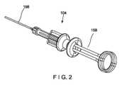
図2で示されるように、アプリケータ104は、例えば、標的組織のクリッピング中に、体外に留まるハンドル部分158に接続された近位端から、例えば、アプリケータ104をクリップ102に接続するためのブッシング118を含む遠位端へと延びるカテーテルなどの可撓性のある部材156を含む。制御部材120は、クリップ102がアプリケータ104に装填された後、クリップ102の移動を制御するための作動器を含むハンドル部分158に接続された近位端から、可撓性のある部材156を通って、拡大された遠位端122へと延びる。 As shown in FIG. 2, the
この実施形態では、ブッシング118は、可撓性のある部材156の遠位端に接続され、かつカプセル108の接続要素116によりクリップ102に接続されるように構成される。ブッシング118は、近位端160から、遠位端162へと延び、かつその中を通って延びるチャネル164を含む。近位端160は、可撓性のある部材154の遠位端に接続されるが、遠位端162は、接続要素116に係合するように構成される。ブッシング118が、カプセル108に結合されると、ブッシング118のチャネル164は、カプセル108のチャネル144と実質的に位置合わせされる。ブッシングは、クリップ102をアプリケータ104に装填する間に、接続要素116に係合するように構成された第1の傾斜部分166と、クリップ102の展開中に、ブッシング118からカプセル108の分離を容易にする第2の傾斜部分168とを含む。第1および第2の傾斜部分166、168は、この実施形態では、首部分170を介して互いに接続される。第1および第2の傾斜部分166、168は、ブッシング118の周辺で延び、また一実施形態では、ブッシング118の実質的に円錐部分を形成する。首部分170は、ブッシング118の実質的に円筒部分に沿って、第1の傾斜部分166から近位方向に、第2の傾斜部分168の遠位端へとブッシング118の周辺で同様に延びる。 In this embodiment,
第1の傾斜部分166の外側面172は、接続要素116の間で、ブッシング118の受入れを容易にするために、遠位端162へとテーパが付いている。第1の傾斜部分166は、その近位端にリップ部174を含み、リップ部174は、第1の傾斜部分166の内側面と、首部分170の外側面176との間に形成された空間により画定される。リップ部174を形成する第1の傾斜部分166の一部は、遠位端162よりも大きな直径を有し、したがって、クリップ102の装填中に、カプセル108が、ブッシング118に対して近位方向に引っ張られると、フック152が、第1の傾斜部分166の外側面172に沿って摺動し、接続要素116が、それらの間で第1の傾斜部分166に適合するように弾性的に変形する。フック152が、近位方向にリップ部174を過ぎて移動した後、接続要素116は、半径方向内側にスナップ嵌合し、その最初の構成に戻る。
この構成では、フック152および第1の傾斜部分166は、フック152の先端154が、リップ部174の縁176に当接する予備的な係合を形成する。さらに以下で詳細に述べられるように、カプセル108およびブッシング118がこの予備的な係合を形成した後、アプリケータ104およびクリップ102をカートリッジ124の外へと引っ張ることは、カートリッジ124の圧着機構146を、接続要素116の近位部分150と係合させて、フック152が、第1の傾斜部分166のリップ部174の上に圧着され、クリップ102をアプリケータ104に装填させるようにする。フック152が、リップ部174の上に圧着された後、クリップ102は、展開されるまで、アプリケータ104のブッシング118に結合された状態に留まる。 In this configuration,
第2の傾斜部分168は、首部分170から近位方向に延びて、そこから外側に広がり、第2の傾斜部分168の近位端178が、首部分170と、リップ部174を含む第1の傾斜部分166の部分との両方よりも大きな直径を有する。クリップ102が、所望の標的組織の上にクリップされた後、クリップ・アーム106が、閉じた構成の状態で、カプセル108に対して固定されるまで(例えば、クリップ・アーム106の固定タブが、カプセル108の固定窓内に受け入れられることにより)、制御部材120は、カプセル108に対して近位方向に引っ張られる。この時点の後に、制御部材120をさらに近位方向に移動することは、カプセル108をブッシング118に対して近位方向に引っ張ることになり、したがって、十分な圧縮力が、接続要素116に加えられたとき、フック152は、第2の傾斜部分166に沿って近位方向に摺動して、カプセル108の長手方向軸から離れる方向に、展開した構成に向けて接続要素116を移動させる。接続要素116は、ブッシング118との係合から外れて展開した構成に向けて塑性変形され、したがって、ブッシング118は、体内に何らかの残存部分を残すことなく、カプセル108の接続要素116との間から近位方向に外され得る。 Second ramped
一実施形態では、接続タブ116は、第1の傾斜部分166と接続要素116の予備的な係合を達成するのに必要なわずかな弾性変形を可能にするように選択された金属から形成され、それは、クリップ102の展開中に塑性的に変形することになる。接続要素116は、例えば、焼鈍または加工硬化(スタンピング、引き抜き、押し出しなどにより)され得るステンレス鋼などの金属から形成され、したがって、ブッシング118の上に圧着されると、何らかの変形を生ずることなく、クリップ102が開いた構成と閉じた構成の間で移動する負荷に耐えることになる。しかし、接続要素116に対して十分な圧縮力が加えられた後、接続タブ116は、展開された構成に向けて塑性変形するようになる。 In one embodiment, connecting
アプリケータ104に装填される前に、本実施形態のクリップ102は、アプリケータ104にクリップ組立体102の装填を容易にするように構成されたカートリッジ124に格納される。カートリッジ124は、図3で示されるように、ベース125および蓋(示されていない)を含む格納容器として構成され、その内部において、クリップ102を収容するような寸法および形状をした空間180が画定される。図3は、容器124のベース125だけを示しているが、対応する蓋がベース125に結合されて、クリップ102を完全に封入することに留意されたい。この実施形態では、クリップ102は、開いた構成でカートリッジ124内に格納される。長手方向スロット182が、空間180から近位方向に延びており、それを通して、アプリケータ104の遠位部分が挿入されて、クリップ組立体102に結合され、それは、以下でさらに詳細に述べられる。 Prior to loading the
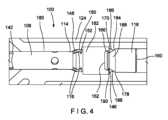
この実施形態では、図4で示されるように、長手方向スロット182は、ブッシング118が、それを越えて遠位方向に移動されることができないように、第2の傾斜部分168の近位端178に係合するような寸法の肩部184として構成された停止部を含む。圧着機構146は、長手方向スロット182内で、肩部184の直ぐ遠位に位置する。この実施形態では、圧着機構146は、傾斜面186が、カプセル108の長手方向軸に対して傾くように、肩部184から、遠位方向外側に広がる傾斜面186として構成される。傾斜面186の近位端188における長手方向スロット182の断面積(例えば、直径)は、傾斜面186の遠位端190における断面積(例えば、直径)よりも小さく、したがって、近位端188は、長手方向スロット182の中に、その中心線に向けて突き出しており、接続要素116に対する圧着を提供する。 In this embodiment, as shown in FIG. 4,
アプリケータ104にクリップ102を装填する間、ブッシング118を含むアプリケータ104の遠位部分は、第2の傾斜部分168の近位端178が肩部184に当接し、ブッシング118がそれを越えて移動しないようにするまで、カートリッジ124の長手方向スロット182を通して挿入される。一実施形態では、制御部材120は、次いで、制御部材120の拡大された遠位端122が、遠位方向にブッシング118を過ぎて延びてヨーク126に係合するまで、可撓性のある部材156に対して遠位方向に移動される。制御部材120がヨーク126内に接続されると、制御部材120は、可撓性のある部材156に対して近位方向に引っ張られて、クリップ102を閉じた構成へと移動する。閉じた構成になった後、制御部材120の続けて行われる近位の動きは、図5で示されるように、カプセル108の近位端114における接続要素116が、第1の傾斜部分166の上に近位方向に移動されるまで、カートリッジ124に対して近位方向にカプセル108を移動させる。 During loading of
別の実施形態では、肩部184は、ユーザが、ブッシング118に接続要素116を直接係合させ、次いで、クリップをブッシング118に完全に圧着するために、組立体全体を最終的にカートリッジ124から外す前に、制御部材120をヨーク126と係合させるように配置され得る。接続要素116のそれぞれのフック152は、第1の傾斜部分166の外側面172に沿って近位方向に摺動し、フック152が近位方向にリップ部174を過ぎて移動するまで、第1の傾斜部分166に適合するように弾性変形し、リップ部174を過ぎた時点で、接続要素116はその初期構成へと復元する。特に、フック152は、図6で示されるように、第1の傾斜部分166の上にスナップ嵌合されて、図6で示されるように、リップ部174に係合するフック152との予備的な係合を形成し、フック152の先端154は、リップ部174の縁部176に係合する。 In another embodiment,
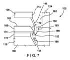
第1の傾斜部分166の上にフック152をスナップ嵌合させることは、ユーザが、カプセル108およびブッシング118が予備的な係合を形成したことに気が付くように、触知可能なフィードバックをユーザに提供する。ユーザは、次いで、アプリケータ104全体をカートリッジ124に対して近位方向に引っ張ることができ、したがって、カプセル108がまた、接続要素116の近位部分150が圧着機構146に係合するまで、カートリッジ124の長手方向スロット182を通して近位方向に引っ張られる。特に、遠位部分のフック152は、図7で示されるように、傾斜面186に沿って近位方向に摺動され、したがって、圧着機構146は、半径方向内側の力と、遠位方向の力を共にフック152に与え、図8で示されるように、第1の傾斜部分166のリップ部174の上にフック152を圧着する。 Snap-fitting
例えば、フック152の先端154は、首部分170の外側面と、傾斜部分166の内側面の間に画定された空間内に受け入れられ得る。接続要素116の近位部分150の残りの部分は、リップ部174の外側面に押し付けられて、クリップ102の開閉する負荷に耐える圧着接続を形成する。クリップ102が、接続要素116の圧着によりアプリケータに装填された後、図9で示されるように、アプリケータ104のさらなる近位の動きが、ブッシング118およびカプセル108を、近位方向に圧着機構146を過ぎて移動させて、組み立てられたクリップ102およびアプリケータ104が、カートリッジ124から取り外され得る。 For example, tip 154 of
使用する場合、クリップ102がアプリケータ104に装填された後、閉じた構成にあるクリップ102は、例えば、内視鏡の作業チャネルを介して、標的組織に隣接する位置へと、体内に挿入される。クリップ102が標的組織に達すると、クリップ102は、開いた構成に向けて移動されて、クリップ・アーム106の遠位端112の間に標的組織を受け入れる。クリップ102は、標的組織が、所望するようにクリップ・アーム106の間にクリップされるまで、開いた構成と閉じた構成に間で移動され得る。クリップ102が、所望するように組織をクリップする閉じた構成になった後、制御部材120は、クリップ・アーム106の固定機構が、カプセル108の対応する固定構造に係合し、閉じた構成で、カプセル108に対してクリップ・アーム106を固定するまで、(例えば、ハンドル部分158の作動器により)カプセル108に対して近位方向に移動される。 In use, after the
アプリケータ104からクリップ102を解放するために、カプセル108が、ブッシング118に対して近位方向に引っ張られて、接続要素116に対する圧縮負荷が所定の閾値を超え、接続要素116を、特にフック152をリップ部174から係合解除させ、第2の傾斜部分168に沿って近位方向に摺動させるまで、制御部材120は、さらに近位方向に引っ張られる。第2の傾斜部分168に沿ってフック152を摺動させることは、接続タブ116を塑性変形させ、したがって、それらが、ブッシング118との係合が外れて、カプセル108の長手方向軸から遠くに、さらに半径方向外側の位置に留まるようにする。ブッシング118は、接続要素116の間から近位方向に引き抜かれて、標的組織をクリップしている場所にクリップ102を残す。 To release
ユーザは、ヨーク126が、点132において破損し、壊れ、またはその他の形で分離するまで、制御部材120に対して近位の力を加え続けて、クリップ・アーム106を、またそれにより、クリップ102を、制御部材120から解放し、クリップ102が標的組織上で閉じられた状態に固定する。制御部材120およびヨーク126の近位部分128を含むアプリケータ104全体は、次いで、体から近位方向に引き抜かれることができ、クリップ102を標的組織上にクリップされた状態で残す。そのようにすることが望ましい場合、新しいクリップ102が、前述のものと同様な方法で、アプリケータ104に装填されることができ、したがって、システム100は、次いで、組織の第2の部分をクリップするために使用され得る。このプロセスは、必要に応じて、または所望に応じて何度も、同じアプリケータ104を使用して繰り返されてもよい。 The user continues to apply proximal force against
接続要素116は、ブッシング118の一部に係合するために、カプセル108から近位方向に延びるものとして述べられ、かつ示されているが、当業者であれば、接続要素116は、クリップのカプセルの対応する部分に係合するために、アプリケータのブッシングから遠位方向に同様に延びることもできることが理解されよう。代替的に、圧着可能な接続要素を含む結合器が、カプセルまたはブッシングのいずれかに取り付けられて、カプセルまたはブッシングの他方の対応する部分の上に圧着され得る。 Although connecting
本開示の範囲から逸脱することなく、本開示に様々な変更がなされ得ることが当業者には明らかであろう。 It will be apparent to those skilled in the art that various modifications can be made to this disclosure without departing from its scope.
Claims (9)
Translated fromJapanese1対のクリップ・アームを含むクリップであって、前記クリップ・アームのそれぞれは、近位端から遠位端へと延び、前記クリップ・アームの近位端は、開いた構成と閉じた構成の間で移動されるように、カプセルのチャネル内に摺動可能に受け入れられ、前記カプセルの近位端は、該カプセルの近位端から近位方向に延びる複数の接続要素を含み、前記接続要素のそれぞれは、該接続要素のそれぞれの近位部分に沿ってフックを含む、クリップと、
細長い可撓性のある部材、および該細長い可撓性のある部材の中を通って延びる制御部材を含むアプリケータであって、前記制御部材は、クリップ組立体を前記開いた構成と前記閉じた構成の間で移動させるために前記クリップ・アームに接続されるように構成された遠位端を含み、前記細長い可撓性のある部材の遠位端は、ブッシングであって、前記ブッシングの遠位端へとテーパの付いた第1の傾斜部分、および前記第1の傾斜部分から近位方向に延びる首部分を含むブッシングを含み、前記第1の傾斜部分の近位端は、前記第1の傾斜部分の内側面と、前記首部分の外側面の間で延びる凹部により画定されるリップ部を含み、前記リップ部は、前記接続要素が前記リップ部の上に圧着されたとき、前記フックに係合するように構成される、アプリケータとを備え、
前記接続要素は、該接続要素に加わる圧縮力が所定の閾値を超えて、前記接続要素が、前記ブッシングの第2の傾斜部分に沿って近位方向に、前記ブッシングが前記接続要素同士の間から解放可能になる展開された構成に向けて摺動したとき、塑性変形するように構成されている再装填可能なクリッピング・システム。A rechargeable clipping system for treating tissue, comprising:
A clip including a pair of clip arms, each extending from a proximal end to a distal end, the proximal ends of the clip arms having an open configuration and a closed configuration. a plurality of connecting elements slidably received within a channel of the capsule, the proximal end of the capsule extending proximally fromthe proximal end of the capsule for movement therebetween; a clip each of which includes a hook along a proximal portionof each of said connecting elements ;
an applicator including anelongated flexible member and a control member extending through the elongated flexible member , the control member configured to position the clip assembly in the open configuration and the closed configuration; a distal end configured to be connected to the clip arm for movement between configurations, the distal end of the elongated flexible member being a bushing; a bushing including a first beveled portion tapering to a proximal end and a neck portion extending proximally from said first beveled portion, the proximal end of said first beveled portion and a lip defined by a recess extending between the inner surface of the tapered portion of the neck portion and the outer surface of the neck portion, the lip portion being aligned when the connecting element is crimped overthe lip portion. an applicator configured to engagethe
The connecting element is configured such that a compressive force applied to the connecting element exceeds a predetermined threshold, the connecting element moving proximally along the second angled portion of the bushing, and the bushing between the connecting elements. A reloadable clipping system configured to plastically deform when slid toward a deployed configuration that is releasable from.
該カートリッジは、前記開いた構成において、前記クリップを前記カートリッジの中に収容するような寸法および形状をした空間と、長手方向スロットとを含み、
該長手方向スロットは、前記空間から近位方向に延び、前記アプリケータの遠位部分を前記長手方向スロットの中に受け入れるような寸法および形状をしている、請求項1乃至3のいずれか1項に記載のシステム。further equipped with a cartridge,
the cartridge includes a space sized and shaped to accommodate the clip withinthe cartridge in the open configuration anda longitudinal slot;
4. Any one of claims 1-3, wherein thelongitudinalslot extends proximally from the space andis sized and shaped to receive a distal portion of the applicator therein. A system as described in .
Priority Applications (1)
| Application Number | Priority Date | Filing Date | Title |
|---|---|---|---|
| JP2023034980AJP7557565B2 (en) | 2019-07-16 | 2023-03-07 | Crimp attachment of clips for reloadable hemostatic devices |
Applications Claiming Priority (3)
| Application Number | Priority Date | Filing Date | Title |
|---|---|---|---|
| US201962874695P | 2019-07-16 | 2019-07-16 | |
| US62/874,695 | 2019-07-16 | ||
| PCT/US2020/038512WO2021011146A1 (en) | 2019-07-16 | 2020-06-18 | Crimp attachment of clip for reloadable hemostasis device |
Related Child Applications (1)
| Application Number | Title | Priority Date | Filing Date |
|---|---|---|---|
| JP2023034980ADivisionJP7557565B2 (en) | 2019-07-16 | 2023-03-07 | Crimp attachment of clips for reloadable hemostatic devices |
Publications (2)
| Publication Number | Publication Date |
|---|---|
| JP2022530965A JP2022530965A (en) | 2022-07-05 |
| JP7241917B2true JP7241917B2 (en) | 2023-03-17 |
Family
ID=71465492
Family Applications (2)
| Application Number | Title | Priority Date | Filing Date |
|---|---|---|---|
| JP2021564457AActiveJP7241917B2 (en) | 2019-07-16 | 2020-06-18 | Crimp attachment of clips for reloadable hemostatic devices |
| JP2023034980AActiveJP7557565B2 (en) | 2019-07-16 | 2023-03-07 | Crimp attachment of clips for reloadable hemostatic devices |
Family Applications After (1)
| Application Number | Title | Priority Date | Filing Date |
|---|---|---|---|
| JP2023034980AActiveJP7557565B2 (en) | 2019-07-16 | 2023-03-07 | Crimp attachment of clips for reloadable hemostatic devices |
Country Status (5)
| Country | Link |
|---|---|
| US (3) | US11883036B2 (en) |
| EP (2) | EP4559412A3 (en) |
| JP (2) | JP7241917B2 (en) |
| CN (2) | CN114007524B (en) |
| WO (1) | WO2021011146A1 (en) |
Families Citing this family (2)
| Publication number | Priority date | Publication date | Assignee | Title |
|---|---|---|---|---|
| WO2021015916A1 (en)* | 2019-07-22 | 2021-01-28 | Boston Scientific Scimed, Inc. | Spring loaded mechanism for the deployment of a hemostatic clip |
| US11937828B2 (en)* | 2021-01-26 | 2024-03-26 | Olympus Medical Systems Corp. | Endoscope treatment device |
Citations (4)
| Publication number | Priority date | Publication date | Assignee | Title |
|---|---|---|---|---|
| WO2004017839A1 (en) | 2002-08-21 | 2004-03-04 | Olympus Corporation | Ligating device for biological tissue |
| JP2006198388A (en) | 2004-12-24 | 2006-08-03 | Olympus Corp | Ligation device |
| WO2017104475A1 (en) | 2015-12-18 | 2017-06-22 | 株式会社カネカ | Connector, medical clip device, and production method for medical clip device |
| US20180153552A1 (en) | 2016-12-06 | 2018-06-07 | Boston Scientific Scimed, Inc. | Compressive coupler for reloadable hemostasis clipping device |
Family Cites Families (14)
| Publication number | Priority date | Publication date | Assignee | Title |
|---|---|---|---|---|
| US6193732B1 (en) | 1999-01-08 | 2001-02-27 | Cardiothoracic System | Surgical clips and apparatus and method for clip placement |
| JP4472217B2 (en) | 2000-10-16 | 2010-06-02 | オリンパス株式会社 | Biological tissue clip device |
| US20020138086A1 (en) | 2000-12-06 | 2002-09-26 | Robert Sixto | Surgical clips particularly useful in the endoluminal treatment of gastroesophageal reflux disease (GERD) |
| EP1670365B1 (en)* | 2003-09-30 | 2018-12-05 | Boston Scientific Scimed, Inc. | Apparatus for deployment of a hemostatic clip |
| AU2004289214B2 (en) | 2003-11-07 | 2011-05-19 | Scimed Life Systems, Inc. | Endoscopic hemoscopic clipping apparatus |
| WO2006062019A1 (en)* | 2004-12-07 | 2006-06-15 | Olympus Corporation | Treatment instrument for endoscope and cartridge in which treatment instrument is received |
| EP3061413B1 (en) | 2008-06-19 | 2022-01-19 | Boston Scientific Scimed, Inc. | Tissue clipping apparatus |
| JP2010193994A (en) | 2009-02-24 | 2010-09-09 | Fujifilm Corp | Clip package, multiple clip system, and mechanism for preventing mismatch of the multiple clip system |
| JP5427858B2 (en)* | 2011-09-15 | 2014-02-26 | 富士フイルム株式会社 | Ligating device and endoscope system |
| SG11201609512VA (en) | 2014-06-10 | 2016-12-29 | Agency Science Tech & Res | Oscillator |
| EP3487422B1 (en)* | 2016-08-22 | 2021-11-03 | Boston Scientific Limited | Hemostasis reloadable clipping device with sleeve engagement |
| US10820903B2 (en)* | 2016-09-22 | 2020-11-03 | Boston Scientific Scimed, Inc. | Hemostasis clip with reloadable clipping mechanism |
| CA3031692C (en)* | 2016-11-22 | 2021-01-19 | Boston Scientific Limited | Hemostasis reloadable clip release mechanism |
| US11076862B2 (en)* | 2018-12-28 | 2021-08-03 | Olympus Corporation | Clip unit, medical instrument, and attaching method of medical instrument |
- 2020
- 2020-06-18JPJP2021564457Apatent/JP7241917B2/enactiveActive
- 2020-06-18EPEP25161970.6Apatent/EP4559412A3/enactivePending
- 2020-06-18CNCN202080041834.0Apatent/CN114007524B/enactiveActive
- 2020-06-18CNCN202510682680.8Apatent/CN120477862A/enactivePending
- 2020-06-18USUS16/905,616patent/US11883036B2/enactiveActive
- 2020-06-18EPEP20736896.0Apatent/EP3937797B1/enactiveActive
- 2020-06-18WOPCT/US2020/038512patent/WO2021011146A1/ennot_activeCeased
- 2023
- 2023-03-07JPJP2023034980Apatent/JP7557565B2/enactiveActive
- 2023-11-22USUS18/517,928patent/US12102336B2/enactiveActive
- 2024
- 2024-08-29USUS18/819,326patent/US20240415522A1/enactivePending
Patent Citations (4)
| Publication number | Priority date | Publication date | Assignee | Title |
|---|---|---|---|---|
| WO2004017839A1 (en) | 2002-08-21 | 2004-03-04 | Olympus Corporation | Ligating device for biological tissue |
| JP2006198388A (en) | 2004-12-24 | 2006-08-03 | Olympus Corp | Ligation device |
| WO2017104475A1 (en) | 2015-12-18 | 2017-06-22 | 株式会社カネカ | Connector, medical clip device, and production method for medical clip device |
| US20180153552A1 (en) | 2016-12-06 | 2018-06-07 | Boston Scientific Scimed, Inc. | Compressive coupler for reloadable hemostasis clipping device |
Also Published As
| Publication number | Publication date |
|---|---|
| CN114007524A (en) | 2022-02-01 |
| US11883036B2 (en) | 2024-01-30 |
| EP3937797B1 (en) | 2025-05-14 |
| CN120477862A (en) | 2025-08-15 |
| EP4559412A3 (en) | 2025-07-30 |
| EP3937797A1 (en) | 2022-01-19 |
| JP7557565B2 (en) | 2024-09-27 |
| EP4559412A2 (en) | 2025-05-28 |
| CN114007524B (en) | 2025-06-10 |
| US20240415522A1 (en) | 2024-12-19 |
| US12102336B2 (en) | 2024-10-01 |
| JP2022530965A (en) | 2022-07-05 |
| WO2021011146A1 (en) | 2021-01-21 |
| US20210015488A1 (en) | 2021-01-21 |
| JP2023071928A (en) | 2023-05-23 |
| US20240081831A1 (en) | 2024-03-14 |
Similar Documents
| Publication | Publication Date | Title |
|---|---|---|
| JP6694975B2 (en) | System for treating tissue | |
| EP3915494B1 (en) | Multiple opening/closing of clip | |
| EP3484379B1 (en) | Partially oval capsule for reloadable hemostasis clipping device | |
| JP6810254B2 (en) | User-operated reloadable clip cartridge | |
| US12102336B2 (en) | Crimp attachment of clip for reloadable hemostasis device | |
| US12102335B2 (en) | Reloadable clip with a flaring capsule deformation | |
| US12127746B2 (en) | Non-shedding coupling method and system for reloadable hemostasis clip |
Legal Events
| Date | Code | Title | Description |
|---|---|---|---|
| A621 | Written request for application examination | Free format text:JAPANESE INTERMEDIATE CODE: A621 Effective date:20211029 | |
| A131 | Notification of reasons for refusal | Free format text:JAPANESE INTERMEDIATE CODE: A131 Effective date:20221025 | |
| A521 | Request for written amendment filed | Free format text:JAPANESE INTERMEDIATE CODE: A523 Effective date:20230125 | |
| TRDD | Decision of grant or rejection written | ||
| A01 | Written decision to grant a patent or to grant a registration (utility model) | Free format text:JAPANESE INTERMEDIATE CODE: A01 Effective date:20230207 | |
| A61 | First payment of annual fees (during grant procedure) | Free format text:JAPANESE INTERMEDIATE CODE: A61 Effective date:20230307 | |
| R150 | Certificate of patent or registration of utility model | Ref document number:7241917 Country of ref document:JP Free format text:JAPANESE INTERMEDIATE CODE: R150 |