JP7232158B2 - Apparatus for producing acidic aqueous solution and method for producing acidic aqueous solution - Google Patents
Apparatus for producing acidic aqueous solution and method for producing acidic aqueous solutionDownload PDFInfo
- Publication number
- JP7232158B2 JP7232158B2JP2019162099AJP2019162099AJP7232158B2JP 7232158 B2JP7232158 B2JP 7232158B2JP 2019162099 AJP2019162099 AJP 2019162099AJP 2019162099 AJP2019162099 AJP 2019162099AJP 7232158 B2JP7232158 B2JP 7232158B2
- Authority
- JP
- Japan
- Prior art keywords
- aqueous solution
- acidic aqueous
- electrodialysis
- producing
- water
- Prior art date
- Legal status (The legal status is an assumption and is not a legal conclusion. Google has not performed a legal analysis and makes no representation as to the accuracy of the status listed.)
- Active
Links
- 239000007864aqueous solutionSubstances0.000titleclaimsdescription219
- 230000002378acidificating effectEffects0.000titleclaimsdescription192
- 238000004519manufacturing processMethods0.000titleclaimsdescription132
- 238000000909electrodialysisMethods0.000claimsdescription196
- XLYOFNOQVPJJNP-UHFFFAOYSA-NwaterSubstancesOXLYOFNOQVPJJNP-UHFFFAOYSA-N0.000claimsdescription136
- MHAJPDPJQMAIIY-UHFFFAOYSA-NHydrogen peroxideChemical compoundOOMHAJPDPJQMAIIY-UHFFFAOYSA-N0.000claimsdescription123
- 239000002351wastewaterSubstances0.000claimsdescription97
- 238000005868electrolysis reactionMethods0.000claimsdescription66
- SUKJFIGYRHOWBL-UHFFFAOYSA-Nsodium hypochloriteChemical compound[Na+].Cl[O-]SUKJFIGYRHOWBL-UHFFFAOYSA-N0.000claimsdescription57
- 239000005708Sodium hypochloriteSubstances0.000claimsdescription55
- 238000011282treatmentMethods0.000claimsdescription48
- 150000002500ionsChemical class0.000claimsdescription39
- 239000003014ion exchange membraneSubstances0.000claimsdescription33
- 239000012528membraneSubstances0.000claimsdescription31
- VEXZGXHMUGYJMC-UHFFFAOYSA-MChloride anionChemical compound[Cl-]VEXZGXHMUGYJMC-UHFFFAOYSA-M0.000claimsdescription20
- 238000009792diffusion processMethods0.000claimsdescription16
- UFHFLCQGNIYNRP-UHFFFAOYSA-NHydrogenChemical group[H][H]UFHFLCQGNIYNRP-UHFFFAOYSA-N0.000claimsdescription15
- 239000011347resinSubstances0.000claimsdescription15
- 229920005989resinPolymers0.000claimsdescription15
- 229910001413alkali metal ionInorganic materials0.000claimsdescription12
- 238000007254oxidation reactionMethods0.000claimsdescription12
- 238000005341cation exchangeMethods0.000claimsdescription6
- 229920001577copolymerPolymers0.000claimsdescription6
- 239000001257hydrogenSubstances0.000claimsdescription6
- 229910052739hydrogenInorganic materials0.000claimsdescription6
- 239000003011anion exchange membraneSubstances0.000claimsdescription5
- 150000002431hydrogenChemical class0.000claimsdescription5
- 229920002873PolyethyleniminePolymers0.000claimsdescription3
- 238000005576amination reactionMethods0.000claimsdescription3
- 238000009833condensationMethods0.000claimsdescription3
- 230000005494condensationEffects0.000claimsdescription3
- 239000005011phenolic resinSubstances0.000claimsdescription3
- 238000006277sulfonation reactionMethods0.000claimsdescription3
- 125000002091cationic groupChemical group0.000claims2
- 229920000867polyelectrolytePolymers0.000claims2
- HEMHJVSKTPXQMS-UHFFFAOYSA-MSodium hydroxideChemical compound[OH-].[Na+]HEMHJVSKTPXQMS-UHFFFAOYSA-M0.000description42
- VEXZGXHMUGYJMC-UHFFFAOYSA-NHydrochloric acidChemical compoundClVEXZGXHMUGYJMC-UHFFFAOYSA-N0.000description38
- 238000000034methodMethods0.000description36
- 230000008569processEffects0.000description27
- 239000003054catalystSubstances0.000description23
- 238000000502dialysisMethods0.000description22
- 238000004065wastewater treatmentMethods0.000description21
- 238000010586diagramMethods0.000description18
- 238000010790dilutionMethods0.000description18
- 239000012895dilutionSubstances0.000description18
- 239000000243solutionSubstances0.000description17
- 229910052751metalInorganic materials0.000description16
- 239000002184metalSubstances0.000description16
- OKTJSMMVPCPJKN-UHFFFAOYSA-NCarbonChemical compound[C]OKTJSMMVPCPJKN-UHFFFAOYSA-N0.000description12
- FAPWRFPIFSIZLT-UHFFFAOYSA-MSodium chlorideChemical compound[Na+].[Cl-]FAPWRFPIFSIZLT-UHFFFAOYSA-M0.000description12
- 230000000694effectsEffects0.000description12
- BASFCYQUMIYNBI-UHFFFAOYSA-NplatinumChemical compound[Pt]BASFCYQUMIYNBI-UHFFFAOYSA-N0.000description12
- 150000001768cationsChemical class0.000description9
- 239000000460chlorineSubstances0.000description9
- 150000003839saltsChemical class0.000description9
- 239000010936titaniumSubstances0.000description9
- CDBYLPFSWZWCQE-UHFFFAOYSA-LSodium CarbonateChemical compound[Na+].[Na+].[O-]C([O-])=OCDBYLPFSWZWCQE-UHFFFAOYSA-L0.000description8
- 150000001450anionsChemical class0.000description8
- 238000006243chemical reactionMethods0.000description8
- 239000000645desinfectantSubstances0.000description8
- 239000007789gasSubstances0.000description8
- ZAMOUSCENKQFHK-UHFFFAOYSA-NChlorine atomChemical compound[Cl]ZAMOUSCENKQFHK-UHFFFAOYSA-N0.000description7
- 229910052801chlorineInorganic materials0.000description7
- 229910052697platinumInorganic materials0.000description7
- VTYYLEPIZMXCLO-UHFFFAOYSA-LCalcium carbonateChemical compound[Ca+2].[O-]C([O-])=OVTYYLEPIZMXCLO-UHFFFAOYSA-L0.000description6
- RTAQQCXQSZGOHL-UHFFFAOYSA-NTitaniumChemical compound[Ti]RTAQQCXQSZGOHL-UHFFFAOYSA-N0.000description6
- 229910052799carbonInorganic materials0.000description6
- 230000003647oxidationEffects0.000description6
- 239000002245particleSubstances0.000description6
- 238000001223reverse osmosisMethods0.000description6
- 239000011780sodium chlorideSubstances0.000description6
- 239000000126substanceSubstances0.000description6
- 239000000758substrateSubstances0.000description6
- 229910052719titaniumInorganic materials0.000description6
- CBENFWSGALASAD-UHFFFAOYSA-NOzoneChemical compound[O-][O+]=OCBENFWSGALASAD-UHFFFAOYSA-N0.000description5
- VYPSYNLAJGMNEJ-UHFFFAOYSA-NSilicium dioxideChemical compoundO=[Si]=OVYPSYNLAJGMNEJ-UHFFFAOYSA-N0.000description5
- 238000004140cleaningMethods0.000description5
- 230000006866deteriorationEffects0.000description5
- 229910052741iridiumInorganic materials0.000description5
- 230000035699permeabilityEffects0.000description5
- MYMOFIZGZYHOMD-UHFFFAOYSA-NDioxygenChemical compoundO=OMYMOFIZGZYHOMD-UHFFFAOYSA-N0.000description4
- 239000002253acidSubstances0.000description4
- 238000009303advanced oxidation process reactionMethods0.000description4
- 229910001882dioxygenInorganic materials0.000description4
- 150000002739metalsChemical class0.000description4
- 239000000203mixtureSubstances0.000description4
- 239000002994raw materialSubstances0.000description4
- 229910000029sodium carbonateInorganic materials0.000description4
- 229910001415sodium ionInorganic materials0.000description4
- OYPRJOBELJOOCE-UHFFFAOYSA-NCalciumChemical compound[Ca]OYPRJOBELJOOCE-UHFFFAOYSA-N0.000description3
- PXHVJJICTQNCMI-UHFFFAOYSA-NNickelChemical compound[Ni]PXHVJJICTQNCMI-UHFFFAOYSA-N0.000description3
- KJTLSVCANCCWHF-UHFFFAOYSA-NRutheniumChemical compound[Ru]KJTLSVCANCCWHF-UHFFFAOYSA-N0.000description3
- 239000003513alkaliSubstances0.000description3
- 239000011575calciumSubstances0.000description3
- 229910052791calciumInorganic materials0.000description3
- 229910000019calcium carbonateInorganic materials0.000description3
- 229910001385heavy metalInorganic materials0.000description3
- 150000004679hydroxidesChemical class0.000description3
- 230000006872improvementEffects0.000description3
- 238000011221initial treatmentMethods0.000description3
- 239000007788liquidSubstances0.000description3
- 238000001471micro-filtrationMethods0.000description3
- 239000002244precipitateSubstances0.000description3
- 238000001556precipitationMethods0.000description3
- 229910052707rutheniumInorganic materials0.000description3
- 238000000926separation methodMethods0.000description3
- 229910052715tantalumInorganic materials0.000description3
- GUVRBAGPIYLISA-UHFFFAOYSA-Ntantalum atomChemical compound[Ta]GUVRBAGPIYLISA-UHFFFAOYSA-N0.000description3
- 239000003643water by typeSubstances0.000description3
- XKRFYHLGVUSROY-UHFFFAOYSA-NArgonChemical compound[Ar]XKRFYHLGVUSROY-UHFFFAOYSA-N0.000description2
- IJGRMHOSHXDMSA-UHFFFAOYSA-NAtomic nitrogenChemical compoundN#NIJGRMHOSHXDMSA-UHFFFAOYSA-N0.000description2
- CPELXLSAUQHCOX-UHFFFAOYSA-MBromideChemical compound[Br-]CPELXLSAUQHCOX-UHFFFAOYSA-M0.000description2
- BHPQYMZQTOCNFJ-UHFFFAOYSA-NCalcium cationChemical compound[Ca+2]BHPQYMZQTOCNFJ-UHFFFAOYSA-N0.000description2
- KZBUYRJDOAKODT-UHFFFAOYSA-NChlorineChemical compoundClClKZBUYRJDOAKODT-UHFFFAOYSA-N0.000description2
- XEEYBQQBJWHFJM-UHFFFAOYSA-NIronChemical compound[Fe]XEEYBQQBJWHFJM-UHFFFAOYSA-N0.000description2
- JLVVSXFLKOJNIY-UHFFFAOYSA-NMagnesium ionChemical compound[Mg+2]JLVVSXFLKOJNIY-UHFFFAOYSA-N0.000description2
- SXDBWCPKPHAZSM-UHFFFAOYSA-Nbromic acidChemical compoundOBr(=O)=OSXDBWCPKPHAZSM-UHFFFAOYSA-N0.000description2
- 229910001424calcium ionInorganic materials0.000description2
- 239000000919ceramicSubstances0.000description2
- 239000013522chelantSubstances0.000description2
- 230000000052comparative effectEffects0.000description2
- 150000001875compoundsChemical class0.000description2
- 239000012141concentrateSubstances0.000description2
- 239000000356contaminantSubstances0.000description2
- 239000003651drinking waterSubstances0.000description2
- 235000020188drinking waterNutrition0.000description2
- 239000004744fabricSubstances0.000description2
- 238000007731hot pressingMethods0.000description2
- QWPPOHNGKGFGJK-UHFFFAOYSA-Nhypochlorous acidChemical compoundClOQWPPOHNGKGFGJK-UHFFFAOYSA-N0.000description2
- 238000009616inductively coupled plasmaMethods0.000description2
- 238000002354inductively-coupled plasma atomic emission spectroscopyMethods0.000description2
- 239000003456ion exchange resinSubstances0.000description2
- 229920003303ion-exchange polymerPolymers0.000description2
- GKOZUEZYRPOHIO-UHFFFAOYSA-Niridium atomChemical compound[Ir]GKOZUEZYRPOHIO-UHFFFAOYSA-N0.000description2
- 229910001425magnesium ionInorganic materials0.000description2
- VNWKTOKETHGBQD-UHFFFAOYSA-NmethaneChemical compoundCVNWKTOKETHGBQD-UHFFFAOYSA-N0.000description2
- 230000007935neutral effectEffects0.000description2
- 229910000510noble metalInorganic materials0.000description2
- 239000000843powderSubstances0.000description2
- 229910052703rhodiumInorganic materials0.000description2
- 239000010948rhodiumSubstances0.000description2
- MHOVAHRLVXNVSD-UHFFFAOYSA-Nrhodium atomChemical compound[Rh]MHOVAHRLVXNVSD-UHFFFAOYSA-N0.000description2
- 239000010865sewageSubstances0.000description2
- 238000007873sievingMethods0.000description2
- 239000000377silicon dioxideSubstances0.000description2
- 239000007787solidSubstances0.000description2
- 238000001179sorption measurementMethods0.000description2
- 238000004659sterilization and disinfectionMethods0.000description2
- 239000008399tap waterSubstances0.000description2
- 235000020679tap waterNutrition0.000description2
- 238000000108ultra-filtrationMethods0.000description2
- 238000005406washingMethods0.000description2
- BVKZGUZCCUSVTD-UHFFFAOYSA-MBicarbonateChemical compoundOC([O-])=OBVKZGUZCCUSVTD-UHFFFAOYSA-M0.000description1
- BVKZGUZCCUSVTD-UHFFFAOYSA-LCarbonateChemical compound[O-]C([O-])=OBVKZGUZCCUSVTD-UHFFFAOYSA-L0.000description1
- FYYHWMGAXLPEAU-UHFFFAOYSA-NMagnesiumChemical compound[Mg]FYYHWMGAXLPEAU-UHFFFAOYSA-N0.000description1
- OAICVXFJPJFONN-UHFFFAOYSA-NPhosphorusChemical compound[P]OAICVXFJPJFONN-UHFFFAOYSA-N0.000description1
- FKNQFGJONOIPTF-UHFFFAOYSA-NSodium cationChemical compound[Na+]FKNQFGJONOIPTF-UHFFFAOYSA-N0.000description1
- QAOWNCQODCNURD-UHFFFAOYSA-NSulfuric acidChemical compoundOS(O)(=O)=OQAOWNCQODCNURD-UHFFFAOYSA-N0.000description1
- 238000002835absorbanceMethods0.000description1
- 238000000862absorption spectrumMethods0.000description1
- 150000007513acidsChemical class0.000description1
- 230000009471actionEffects0.000description1
- 238000005273aerationMethods0.000description1
- 239000000956alloySubstances0.000description1
- 229910045601alloyInorganic materials0.000description1
- 238000004458analytical methodMethods0.000description1
- 230000000844anti-bacterial effectEffects0.000description1
- 229910052786argonInorganic materials0.000description1
- QVGXLLKOCUKJST-UHFFFAOYSA-Natomic oxygenChemical compound[O]QVGXLLKOCUKJST-UHFFFAOYSA-N0.000description1
- 239000002585baseSubstances0.000description1
- 230000008901benefitEffects0.000description1
- 238000010170biological methodMethods0.000description1
- 238000005422blastingMethods0.000description1
- 238000001354calcinationMethods0.000description1
- 239000003575carbonaceous materialSubstances0.000description1
- 239000000969carrierSubstances0.000description1
- 229920006317cationic polymerPolymers0.000description1
- 238000000262chemical ionisation mass spectrometryMethods0.000description1
- 238000005345coagulationMethods0.000description1
- 230000015271coagulationEffects0.000description1
- 239000008119colloidal silicaSubstances0.000description1
- 239000004020conductorSubstances0.000description1
- 230000007797corrosionEffects0.000description1
- 238000005260corrosionMethods0.000description1
- 238000002788crimpingMethods0.000description1
- 238000000354decomposition reactionMethods0.000description1
- 230000002542deteriorative effectEffects0.000description1
- 238000007865dilutingMethods0.000description1
- 239000003085diluting agentSubstances0.000description1
- 238000007599dischargingMethods0.000description1
- 239000003792electrolyteSubstances0.000description1
- 238000004993emission spectroscopyMethods0.000description1
- 238000005530etchingMethods0.000description1
- 210000003608feceAnatomy0.000description1
- 238000000855fermentationMethods0.000description1
- 230000004151fermentationEffects0.000description1
- 239000008394flocculating agentSubstances0.000description1
- XLYOFNOQVPJJNP-ZSJDYOACSA-Nheavy waterSubstances[2H]O[2H]XLYOFNOQVPJJNP-ZSJDYOACSA-N0.000description1
- 230000002209hydrophobic effectEffects0.000description1
- -1hypochlorous acid ionsChemical class0.000description1
- 239000012535impuritySubstances0.000description1
- 238000007733ion platingMethods0.000description1
- 229910052742ironInorganic materials0.000description1
- 239000010871livestock manureSubstances0.000description1
- 230000007774longtermEffects0.000description1
- 239000011777magnesiumSubstances0.000description1
- 229910052749magnesiumInorganic materials0.000description1
- 239000000463materialSubstances0.000description1
- 244000005700microbiomeSpecies0.000description1
- 238000002156mixingMethods0.000description1
- 229910052759nickelInorganic materials0.000description1
- 229910052757nitrogenInorganic materials0.000description1
- 239000007800oxidant agentSubstances0.000description1
- 239000001301oxygenSubstances0.000description1
- 229910052760oxygenInorganic materials0.000description1
- DCKVFVYPWDKYDN-UHFFFAOYSA-Loxygen(2-);titanium(4+);sulfateChemical compound[O-2].[Ti+4].[O-]S([O-])(=O)=ODCKVFVYPWDKYDN-UHFFFAOYSA-L0.000description1
- 230000020477pH reductionEffects0.000description1
- 230000002085persistent effectEffects0.000description1
- 229910052698phosphorusInorganic materials0.000description1
- 239000011574phosphorusSubstances0.000description1
- 238000000053physical methodMethods0.000description1
- 238000007750plasma sprayingMethods0.000description1
- 239000005518polymer electrolyteSubstances0.000description1
- 238000002360preparation methodMethods0.000description1
- 230000001737promoting effectEffects0.000description1
- 238000006722reduction reactionMethods0.000description1
- 238000007788rougheningMethods0.000description1
- 238000009287sand filtrationMethods0.000description1
- 239000013535sea waterSubstances0.000description1
- 238000004062sedimentationMethods0.000description1
- 239000010802sludgeSubstances0.000description1
- 239000002689soilSubstances0.000description1
- 239000010935stainless steelSubstances0.000description1
- 229910001220stainless steelInorganic materials0.000description1
- 238000003860storageMethods0.000description1
- 229910000348titanium sulfateInorganic materials0.000description1
- 238000004448titrationMethods0.000description1
Images


Classifications
- C—CHEMISTRY; METALLURGY
- C02—TREATMENT OF WATER, WASTE WATER, SEWAGE, OR SLUDGE
- C02F—TREATMENT OF WATER, WASTE WATER, SEWAGE, OR SLUDGE
- C02F1/00—Treatment of water, waste water, or sewage
- C02F1/46—Treatment of water, waste water, or sewage by electrochemical methods
- C02F1/461—Treatment of water, waste water, or sewage by electrochemical methods by electrolysis
- C02F1/46104—Devices therefor; Their operating or servicing
- C02F1/4618—Devices therefor; Their operating or servicing for producing "ionised" acidic or basic water
- B—PERFORMING OPERATIONS; TRANSPORTING
- B01—PHYSICAL OR CHEMICAL PROCESSES OR APPARATUS IN GENERAL
- B01D—SEPARATION
- B01D61/00—Processes of separation using semi-permeable membranes, e.g. dialysis, osmosis or ultrafiltration; Apparatus, accessories or auxiliary operations specially adapted therefor
- B01D61/42—Electrodialysis; Electro-osmosis ; Electro-ultrafiltration; Membrane capacitive deionization
- B01D61/44—Ion-selective electrodialysis
- B01D61/46—Apparatus therefor
- B01D61/463—Apparatus therefor comprising the membrane sequence AC or CA, where C is a cation exchange membrane
- C—CHEMISTRY; METALLURGY
- C02—TREATMENT OF WATER, WASTE WATER, SEWAGE, OR SLUDGE
- C02F—TREATMENT OF WATER, WASTE WATER, SEWAGE, OR SLUDGE
- C02F1/00—Treatment of water, waste water, or sewage
- C02F1/46—Treatment of water, waste water, or sewage by electrochemical methods
- C02F1/461—Treatment of water, waste water, or sewage by electrochemical methods by electrolysis
- C02F1/46104—Devices therefor; Their operating or servicing
- C02F1/46109—Electrodes
- C—CHEMISTRY; METALLURGY
- C02—TREATMENT OF WATER, WASTE WATER, SEWAGE, OR SLUDGE
- C02F—TREATMENT OF WATER, WASTE WATER, SEWAGE, OR SLUDGE
- C02F1/00—Treatment of water, waste water, or sewage
- C02F1/46—Treatment of water, waste water, or sewage by electrochemical methods
- C02F1/469—Treatment of water, waste water, or sewage by electrochemical methods by electrochemical separation, e.g. by electro-osmosis, electrodialysis, electrophoresis
- C02F1/4693—Treatment of water, waste water, or sewage by electrochemical methods by electrochemical separation, e.g. by electro-osmosis, electrodialysis, electrophoresis electrodialysis
- C—CHEMISTRY; METALLURGY
- C25—ELECTROLYTIC OR ELECTROPHORETIC PROCESSES; APPARATUS THEREFOR
- C25B—ELECTROLYTIC OR ELECTROPHORETIC PROCESSES FOR THE PRODUCTION OF COMPOUNDS OR NON-METALS; APPARATUS THEREFOR
- C25B1/00—Electrolytic production of inorganic compounds or non-metals
- C25B1/01—Products
- C25B1/24—Halogens or compounds thereof
- C25B1/26—Chlorine; Compounds thereof
- C—CHEMISTRY; METALLURGY
- C25—ELECTROLYTIC OR ELECTROPHORETIC PROCESSES; APPARATUS THEREFOR
- C25B—ELECTROLYTIC OR ELECTROPHORETIC PROCESSES FOR THE PRODUCTION OF COMPOUNDS OR NON-METALS; APPARATUS THEREFOR
- C25B1/00—Electrolytic production of inorganic compounds or non-metals
- C25B1/01—Products
- C25B1/28—Per-compounds
- C25B1/30—Peroxides
- B—PERFORMING OPERATIONS; TRANSPORTING
- B01—PHYSICAL OR CHEMICAL PROCESSES OR APPARATUS IN GENERAL
- B01D—SEPARATION
- B01D2311/00—Details relating to membrane separation process operations and control
- B01D2311/08—Specific process operations in the concentrate stream
- B—PERFORMING OPERATIONS; TRANSPORTING
- B01—PHYSICAL OR CHEMICAL PROCESSES OR APPARATUS IN GENERAL
- B01D—SEPARATION
- B01D2311/00—Details relating to membrane separation process operations and control
- B01D2311/18—Details relating to membrane separation process operations and control pH control
- B—PERFORMING OPERATIONS; TRANSPORTING
- B01—PHYSICAL OR CHEMICAL PROCESSES OR APPARATUS IN GENERAL
- B01D—SEPARATION
- B01D2311/00—Details relating to membrane separation process operations and control
- B01D2311/25—Recirculation, recycling or bypass, e.g. recirculation of concentrate into the feed
- B01D2311/252—Recirculation of concentrate
- B01D2311/2523—Recirculation of concentrate to feed side
- B—PERFORMING OPERATIONS; TRANSPORTING
- B01—PHYSICAL OR CHEMICAL PROCESSES OR APPARATUS IN GENERAL
- B01D—SEPARATION
- B01D2311/00—Details relating to membrane separation process operations and control
- B01D2311/26—Further operations combined with membrane separation processes
- B01D2311/2684—Electrochemical processes
- C—CHEMISTRY; METALLURGY
- C02—TREATMENT OF WATER, WASTE WATER, SEWAGE, OR SLUDGE
- C02F—TREATMENT OF WATER, WASTE WATER, SEWAGE, OR SLUDGE
- C02F1/00—Treatment of water, waste water, or sewage
- C02F1/46—Treatment of water, waste water, or sewage by electrochemical methods
- C02F1/461—Treatment of water, waste water, or sewage by electrochemical methods by electrolysis
- C02F1/467—Treatment of water, waste water, or sewage by electrochemical methods by electrolysis by electrochemical disinfection; by electrooxydation or by electroreduction
- C02F1/4672—Treatment of water, waste water, or sewage by electrochemical methods by electrolysis by electrochemical disinfection; by electrooxydation or by electroreduction by electrooxydation
- C02F1/4674—Treatment of water, waste water, or sewage by electrochemical methods by electrolysis by electrochemical disinfection; by electrooxydation or by electroreduction by electrooxydation with halogen or compound of halogens, e.g. chlorine, bromine
- C—CHEMISTRY; METALLURGY
- C02—TREATMENT OF WATER, WASTE WATER, SEWAGE, OR SLUDGE
- C02F—TREATMENT OF WATER, WASTE WATER, SEWAGE, OR SLUDGE
- C02F1/00—Treatment of water, waste water, or sewage
- C02F1/46—Treatment of water, waste water, or sewage by electrochemical methods
- C02F1/461—Treatment of water, waste water, or sewage by electrochemical methods by electrolysis
- C02F1/46104—Devices therefor; Their operating or servicing
- C02F1/46109—Electrodes
- C02F2001/46133—Electrodes characterised by the material
- C02F2001/46138—Electrodes comprising a substrate and a coating
- C02F2001/46142—Catalytic coating
- C—CHEMISTRY; METALLURGY
- C02—TREATMENT OF WATER, WASTE WATER, SEWAGE, OR SLUDGE
- C02F—TREATMENT OF WATER, WASTE WATER, SEWAGE, OR SLUDGE
- C02F1/00—Treatment of water, waste water, or sewage
- C02F1/46—Treatment of water, waste water, or sewage by electrochemical methods
- C02F1/461—Treatment of water, waste water, or sewage by electrochemical methods by electrolysis
- C02F1/46104—Devices therefor; Their operating or servicing
- C02F1/46109—Electrodes
- C02F2001/46152—Electrodes characterised by the shape or form
- C02F2001/46157—Perforated or foraminous electrodes
- C02F2001/46161—Porous electrodes
- C02F2001/46166—Gas diffusion electrodes
- C—CHEMISTRY; METALLURGY
- C02—TREATMENT OF WATER, WASTE WATER, SEWAGE, OR SLUDGE
- C02F—TREATMENT OF WATER, WASTE WATER, SEWAGE, OR SLUDGE
- C02F1/00—Treatment of water, waste water, or sewage
- C02F1/46—Treatment of water, waste water, or sewage by electrochemical methods
- C02F1/461—Treatment of water, waste water, or sewage by electrochemical methods by electrolysis
- C02F1/46104—Devices therefor; Their operating or servicing
- C02F1/4618—Devices therefor; Their operating or servicing for producing "ionised" acidic or basic water
- C02F2001/46185—Devices therefor; Their operating or servicing for producing "ionised" acidic or basic water only anodic or acidic water, e.g. for oxidizing or sterilizing
- C—CHEMISTRY; METALLURGY
- C02—TREATMENT OF WATER, WASTE WATER, SEWAGE, OR SLUDGE
- C02F—TREATMENT OF WATER, WASTE WATER, SEWAGE, OR SLUDGE
- C02F2201/00—Apparatus for treatment of water, waste water or sewage
- C02F2201/46—Apparatus for electrochemical processes
- C02F2201/461—Electrolysis apparatus
- C02F2201/46105—Details relating to the electrolytic devices
- C02F2201/4618—Supplying or removing reactants or electrolyte
- C02F2201/46185—Recycling the cathodic or anodic feed
- C—CHEMISTRY; METALLURGY
- C02—TREATMENT OF WATER, WASTE WATER, SEWAGE, OR SLUDGE
- C02F—TREATMENT OF WATER, WASTE WATER, SEWAGE, OR SLUDGE
- C02F2303/00—Specific treatment goals
- C02F2303/14—Maintenance of water treatment installations
Landscapes
- Chemical & Material Sciences (AREA)
- Chemical Kinetics & Catalysis (AREA)
- Engineering & Computer Science (AREA)
- Water Supply & Treatment (AREA)
- Organic Chemistry (AREA)
- Electrochemistry (AREA)
- Life Sciences & Earth Sciences (AREA)
- Hydrology & Water Resources (AREA)
- Environmental & Geological Engineering (AREA)
- General Chemical & Material Sciences (AREA)
- Health & Medical Sciences (AREA)
- Inorganic Chemistry (AREA)
- Materials Engineering (AREA)
- Metallurgy (AREA)
- Molecular Biology (AREA)
- Analytical Chemistry (AREA)
- Urology & Nephrology (AREA)
- Water Treatment By Electricity Or Magnetism (AREA)
- Separation Using Semi-Permeable Membranes (AREA)
Description
Translated fromJapanese本発明は、酸性水溶液の製造装置及び酸性水溶液の製造方法に関する。 TECHNICAL FIELD The present invention relates to an apparatus for producing an acidic aqueous solution and a method for producing an acidic aqueous solution.
排水処理のプロセスでは、排水を処理するために、酸性水溶液の添加が必須となっている。例えば、排水処理のプロセスを正常に機能させるために、酸性水溶液を添加して、pHの調整が行われる。また、装置によっては、定期的に該装置を化学的、物理的に洗浄する必要があり、その際に酸性水溶液を使用する必要がある。例えば、キレート処理、イオン交換樹脂等ではそれらを定期的に酸性水溶液で洗浄して、性能を回復させる必要がある。 In the wastewater treatment process, the addition of an acidic aqueous solution is essential to treat the wastewater. For example, an acidic aqueous solution is added to adjust the pH so that the process of waste water treatment functions normally. Moreover, depending on the device, it is necessary to periodically chemically and physically clean the device, and at that time, it is necessary to use an acidic aqueous solution. For example, chelate treatment, ion-exchange resins, etc. need to be periodically washed with an acidic aqueous solution to restore their performance.
一方で、上記排水処理のプロセスで使用する酸性水溶液は、外部から搬送して、貯蔵する必要があるため、経済的な負担が大きかった。 On the other hand, the acidic aqueous solution used in the wastewater treatment process has to be transported from the outside and stored, which has been a heavy economic burden.
これに対して、例えば特許文献1では、塩類及び有機物を含有する有機性廃水に対して軟化処理を行ってカルシウム濃度を低減させる第1軟化処理装置と、生物処理、凝集沈殿処理、活性炭吸着処理、砂ろ過処理、精密ろ過膜処理からなる群から選ばれる1以上の処理または2以上の組み合わせからなるSS除去処理装置と、電気透析処理により電気透析濃縮水と電気透析処理水とに分離する電気透析処理装置、逆浸透膜処理により逆浸透濃縮水と逆浸透膜処理水とに分離する逆浸透膜処理装置、NF膜処理によりNF膜濃縮水とNF膜処理水とに分離するNF膜処理装置のうちの何れかの装置或いはこれらのうちの2種類以上の装置を含む塩類除去装置と、前記電気透析濃縮水、逆浸透濃縮水又はNF膜濃縮水に対して、軟化処理を行ってカルシウム濃度を低減させる第2軟化処理装置と、第2軟化処理装置で得られた第2軟化処理水を電気分解して次亜塩素酸ナトリウム溶液を生成する電解処理装置と、を備えた有機性廃水の処理装置が開示されている。 On the other hand, for example, in Patent Document 1, a first softening treatment apparatus that softens organic wastewater containing salts and organic substances to reduce the calcium concentration, biological treatment, coagulation sedimentation treatment, and activated carbon adsorption treatment , sand filtration treatment, microfiltration membrane treatment, an SS removal treatment device consisting of one or more treatments or a combination of two or more selected from the group consisting of, and electrodialysis treatment to separate electrodialysis concentrated water and electrodialysis treated water. Dialysis treatment equipment, reverse osmosis membrane treatment equipment that separates reverse osmosis concentrated water and reverse osmosis membrane treated water by reverse osmosis membrane treatment, NF membrane treatment equipment that separates NF membrane concentrated water and NF membrane treated water by NF membrane treatment Any one of these devices or a salt removal device including two or more of these devices, and the electrodialysis concentrated water, reverse osmosis concentrated water or NF membrane concentrated water are subjected to a softening treatment to reduce the calcium concentration of organic wastewater, comprising a second softening device that reduces the A processing device is disclosed.
また、特許文献2では、被処理排水を前置電気透析槽の希釈液室に供給し、前置電気透析槽内でイオン交換膜を透過したイオンが中和して生成した塩を含む濃縮液を、陽イオン交換膜と陰イオン交換膜を隔膜とする陽極室、中央室、陰極室の3室を単位として構成される電解透析槽に供給して塩を構成する酸と塩基に分解して回収する、一価イオンの中性塩を含む排水の処理方法及び該処理方法を適用する処理装置が開示されている。 In addition, in
ところで、排水処理において、排水処理のプロセスで使用する酸性水溶液をオンサイトで製造、利用することができれば、該酸性水溶液を外部から搬送して、貯蔵する必要がなくなり、経済的な負担を大幅に低減することができると考えられる。 By the way, in wastewater treatment, if the acidic aqueous solution used in the wastewater treatment process can be produced and used on-site, the acidic aqueous solution does not need to be transported from the outside and stored, resulting in a significant economic burden. can be reduced.
本発明は、上記事情に鑑みてなされたものであって、排水処理のプロセスで使用する酸性水溶液をオンサイトで製造、利用することができ、経済的な負担を大幅に低減することのできる酸性水溶液の製造装置及び酸性水溶液の製造方法を提供することを目的とする。 The present invention has been made in view of the above circumstances, and the acidic aqueous solution used in the wastewater treatment process can be produced and used on-site, and can greatly reduce the economic burden. An object of the present invention is to provide an apparatus for producing an aqueous solution and a method for producing an acidic aqueous solution.
上記の課題を解決するために、本発明は以下の構成を採用した。
すなわち、本発明の第1の態様は、塩化物イオン及びアルカリ金属イオンを含む排水から酸性水溶液を製造する酸性水溶液の製造装置であって、1価イオン選択透過性イオン交換膜を有し、前記排水を電気透析処理により電気透析濃縮水と電気透析希釈水とに分離する電気透析装置と、前記電気透析濃縮水を電気分解して、酸性水溶液を製造する電気分解装置と、前記酸性水溶液の少なくとも一部を、前記電気透析装置に供給される前記排水に循環させる第1の循環部とを備える、酸性水溶液の製造装置である。In order to solve the above problems, the present invention employs the following configurations.
That is, a first aspect of the present invention is an acidic aqueous solution producing apparatus for producing an acidic aqueous solution from waste water containing chloride ions and alkali metal ions, comprising a monovalent ion permselective ion exchange membrane, An electrodialysis device that separates wastewater into electrodialysis concentrated water and electrodialysis diluted water by electrodialysis treatment, an electrolysis device that electrolyzes the electrodialysis concentrated water to produce an acidic aqueous solution, and at least the acidic aqueous solution and a first circulation part for circulating a part of the waste water to be supplied to the electrodialysis device.
本発明の第1の態様に係る酸性水溶液の製造装置において、さらに、前記酸性水溶液の少なくとも一部を前記電気分解装置に循環させる第2の循環部を備えていてもよい。 The apparatus for producing an acidic aqueous solution according to the first aspect of the present invention may further include a second circulation unit that circulates at least part of the acidic aqueous solution to the electrolyzer.
本発明の第1の態様に係る酸性水溶液の製造装置において、前記電気分解装置は、アノードが水素ガス拡散電極であってもよい。 In the apparatus for producing an acidic aqueous solution according to the first aspect of the present invention, the anode of the electrolyzer may be a hydrogen gas diffusion electrode.
本発明の第1の態様に係る酸性水溶液の製造装置において、さらに、前記電気透析濃縮水の一部を電気分解して、次亜塩素酸ナトリウム水溶液を製造する次亜塩素酸ナトリウム製造装置を備えていてもよい。 The apparatus for producing an acidic aqueous solution according to the first aspect of the present invention further comprises a sodium hypochlorite production apparatus for producing an aqueous sodium hypochlorite solution by electrolyzing a portion of the electrodialysis concentrated water. may be
本発明の第1の態様に係る酸性水溶液の製造装置において、さらに、前記電気透析濃縮水の一部を電気分解して、過酸化水素を製造する過酸化水素製造装置を備えていてもよい。 The apparatus for producing an acidic aqueous solution according to the first aspect of the present invention may further include a hydrogen peroxide production apparatus that electrolyzes a portion of the electrodialysis concentrated water to produce hydrogen peroxide.
本発明の第2の態様は、塩化物イオン及びアルカリ金属イオンを含む排水から、酸性水溶液を製造する酸性水溶液の製造方法であって、前記排水を電気透析処理により電気透析濃縮水と電気透析希釈水とに分離する電気透析工程と、前記電気透析濃縮水を電気分解して、酸性水溶液を製造する電気分解工程と、前記酸性水溶液の少なくとも一部を、前記電気透析工程に供給される前記排水に循環させる第1の循環工程とを有する、酸性水溶液の製造方法である。 A second aspect of the present invention is a method for producing an acidic aqueous solution from wastewater containing chloride ions and alkali metal ions, wherein the wastewater is subjected to electrodialysis treatment to electrodialyze concentrated water and electrodialysis dilution. an electrodialysis step of separating into water, an electrolysis step of electrolyzing the electrodialysis concentrated water to produce an acidic aqueous solution, and at least part of the acidic aqueous solution being supplied to the electrodialysis step. A method for producing an acidic aqueous solution, comprising a first circulation step of circulating to.
本発明の第2の態様に係る酸性水溶液の製造方法において、さらに、前記酸性水溶液の少なくとも一部を前記電気分解工程で用いる第2の循環工程を有していてもよい。 The method for producing an acidic aqueous solution according to the second aspect of the present invention may further include a second circulation step of using at least part of the acidic aqueous solution in the electrolysis step.
本発明の第2の態様に係る酸性水溶液の製造方法において、前記電気分解工程を水素酸化反応によって行ってもよい。 In the method for producing an acidic aqueous solution according to the second aspect of the present invention, the electrolysis step may be performed by a hydrogen oxidation reaction.
本発明の第2の態様に係る酸性水溶液の製造方法において、さらに、前記電気透析濃縮水の一部を電気分解して、次亜塩素酸ナトリウム水溶液を製造する次亜塩素酸ナトリウム製造工程を有していてもよい。 The method for producing an acidic aqueous solution according to the second aspect of the present invention further includes a sodium hypochlorite producing step of electrolyzing a part of the electrodialysis concentrated water to produce an aqueous sodium hypochlorite solution. You may have
本発明の第2の態様に係る酸性水溶液の製造方法において、さらに、前記電気透析濃縮水の一部を電気分解して、過酸化水素を製造する過酸化水素製造を有していてもよい。 The method for producing an acidic aqueous solution according to the second aspect of the present invention may further include producing hydrogen peroxide by electrolyzing a portion of the electrodialysis concentrated water to produce hydrogen peroxide.
本発明の酸性水溶液の製造装置及び酸性水溶液の製造方法によれば、排水処理のプロセスで使用する酸性水溶液をオンサイトで製造、利用することができ、経済的な負担を大幅に低減することができる。 According to the apparatus for producing an acidic aqueous solution and the method for producing an acidic aqueous solution of the present invention, the acidic aqueous solution used in the wastewater treatment process can be produced and used on-site, and the economic burden can be greatly reduced. can.
[概要]
近年、人口増加、生活水準の向上に伴い、上水使用量が増加して、水資源が不足している。また、河川や排水の水質劣化が進行して、その対策が世界各地で急務となっている。例えば、水資源の持続的な使用を目的として、再生水を利用するための事業が検討されている。[overview]
In recent years, with the increase in population and the improvement of living standards, the consumption of clean water has increased, resulting in a shortage of water resources. In addition, the water quality of rivers and wastewater is deteriorating, and countermeasures are urgently needed all over the world. For example, for the purpose of sustainable use of water resources, projects for using reclaimed water are being considered.
排水処理は、一般的に、1次処理、2次処理、3次処理に分かれる。
1次処理では、大きなごみ(SS:浮遊物質;具体的には、ふん尿が混合した汚水中の固形物)を除去する処理である。
2次処理では、1次処理で取り除けなかった汚水中の有機物を微生物の働きによって除去する処理である。具体的には、簡易ばっ気処理、活性汚泥処理、メタン発酵処理等を行う。
3次処理(高度処理、後処理)では、窒素、リン、難分解性物質等を化学的、物理的、生物学的方法で除去する。
化学的処理としては、凝集剤などを用いた汚濁物質分離、オゾンなどの酸化剤により汚濁物質分解等が挙げられる。
物理的処理としては、活性炭吸着や膜処理による分離がある。
該膜処理による分離に用いられる膜としては、逆浸透膜(RO膜;Reverse osmosis membrane)、限外ろ過膜(UF膜;Ultrafiltration membrane)、精密ろ過膜(MF膜;Microfiltration membrane)等が利用されている。Wastewater treatment is generally divided into primary treatment, secondary treatment and tertiary treatment.
In the primary treatment, large garbage (SS: suspended solids; specifically, solid matter in sewage mixed with manure) is removed.
In the secondary treatment, the organic substances in the sewage that could not be removed in the primary treatment are removed by the action of microorganisms. Specifically, simple aeration treatment, activated sludge treatment, methane fermentation treatment, etc. are performed.
In the tertiary treatment (advanced treatment, post-treatment), nitrogen, phosphorus, persistent substances, etc. are removed by chemical, physical and biological methods.
Examples of chemical treatment include separation of contaminants using a flocculating agent and decomposition of contaminants using an oxidizing agent such as ozone.
Physical treatments include separation by activated carbon adsorption and membrane treatment.
As the membrane used for separation by the membrane treatment, a reverse osmosis membrane (RO membrane), an ultrafiltration membrane (UF membrane; Ultrafiltration membrane), a microfiltration membrane (MF membrane; Microfiltration membrane), etc. are used. ing.
上記排水処理のプロセスでは、排水を処理するために、酸性水溶液の添加が必須となっている。例えば、排水処理のプロセスを正常に機能させるために、酸性水溶液を添加して、pHの調整が行われる。また、装置によっては、定期的に該装置を化学的、物理的に洗浄する必要があり、その際に酸性水溶液を使用する必要がある。例えば、キレート処理、イオン交換樹脂等ではそれらを定期的に酸性水溶液で洗浄して、性能を回復させる必要がある。 In the wastewater treatment process described above, the addition of an acidic aqueous solution is essential in order to treat the wastewater. For example, an acidic aqueous solution is added to adjust the pH so that the process of waste water treatment functions normally. Moreover, depending on the device, it is necessary to periodically chemically and physically clean the device, and at that time, it is necessary to use an acidic aqueous solution. For example, chelate treatment, ion-exchange resins, etc. need to be periodically washed with an acidic aqueous solution to restore their performance.
一方で、上記排水処理のプロセスで使用する酸性水溶液は、外部から搬送して、貯蔵する必要があるため、経済的な負担が大きかった。 On the other hand, the acidic aqueous solution used in the wastewater treatment process has to be transported from the outside and stored, which has been a heavy economic burden.
上述した特許文献1に記載されている従来の有機性廃水の処理装置では、次亜塩素酸ナトリウムを製造することはできるが、排水処理のプロセスで使用する酸性水溶液をオンサイトで製造することはできなかった。
また、特許文献2に記載されている排水の処理装置では、酸性水溶液を外部から搬送するという問題は解決できるものの、生成した酸性水溶液を貯蔵しなければならないという問題は解決されていない。そのため、従来の処理方法では、排水処理のプロセスで使用する酸性水溶液をオンサイトで製造、利用することはできなかった。The conventional organic wastewater treatment apparatus described in the above-mentioned Patent Document 1 can produce sodium hypochlorite, but it is impossible to produce an acidic aqueous solution used in the wastewater treatment process on-site. could not.
In addition, although the wastewater treatment apparatus described in
本実施形態の酸性水溶液の製造装置は、塩化物イオン及びアルカリ金属イオンを含む排水(以下、単に排水ともいう)から酸性水溶液を製造する酸性水溶液の製造装置であって、1価イオン選択透過性イオン交換膜を有し、前記排水を電気透析処理により電気透析濃縮水と電気透析希釈水とに分離する電気透析装置と、前記電気透析濃縮水を電気分解して、酸性水溶液を製造する電気分解装置と、前記酸性水溶液の少なくとも一部を、前記電気透析装置に供給される前記排水に循環させる第1の循環部とを備えるものである。これにより、排水処理のプロセスで使用する酸性水溶液をオンサイトで現地生成・現地消費という完結型(Zero Chemical Charge(ZCC):薬品無投入化)様式を達成することができ、経済的な負担を大幅に低減することができる。 The apparatus for producing an acidic aqueous solution of the present embodiment is an apparatus for producing an acidic aqueous solution from waste water containing chloride ions and alkali metal ions (hereinafter also simply referred to as waste water). An electrodialysis device having an ion-exchange membrane and separating the wastewater into electrodialysis concentrated water and electrodialysis diluted water by electrodialysis; and electrolysis for producing an acidic aqueous solution by electrolyzing the electrodialysis concentrated water. and a first circulation unit that circulates at least part of the acidic aqueous solution to the waste water supplied to the electrodialysis apparatus. As a result, the acidic aqueous solution used in the wastewater treatment process can be produced on-site and consumed locally (zero chemical charge (ZCC)), reducing the economic burden. can be significantly reduced.
(酸性水溶液の製造装置)
本発明の第1の態様は、塩化物イオン及びアルカリ金属イオンを含む排水から酸性水溶液を製造する酸性水溶液の製造装置であって、1価イオン選択透過性イオン交換膜を有し、前記排水を電気透析処理により電気透析濃縮水と電気透析希釈水とに分離する電気透析装置と、前記電気透析濃縮水を電気分解して、酸性水溶液を製造する電気分解装置と、前記酸性水溶液の少なくとも一部を、前記電気透析装置に供給される前記排水に循環させる第1の循環部とを備える、酸性水溶液の製造装置である。(Equipment for producing acidic aqueous solution)
A first aspect of the present invention is an acidic aqueous solution producing apparatus for producing an acidic aqueous solution from waste water containing chloride ions and alkali metal ions, comprising a monovalent ion permselective ion exchange membrane, An electrodialysis device that separates electrodialysis concentrated water and electrodialysis diluted water by electrodialysis treatment, an electrolysis device that electrolyzes the electrodialysis concentrated water to produce an acidic aqueous solution, and at least part of the acidic aqueous solution to the waste water supplied to the electrodialysis device.
<第1の実施形態の酸性水溶液の製造装置>
第1の実施形態の酸性水溶液の製造装置は、電気透析装置と、電気分解装置と、第1の循環部とを備える。
第1の実施形態の酸性水溶液の製造装置について、図1を用いて詳細に説明する。<Apparatus for Producing Acidic Aqueous Solution of First Embodiment>
The apparatus for producing an acidic aqueous solution of the first embodiment includes an electrodialysis device, an electrolysis device, and a first circulation unit.
The apparatus for producing an acidic aqueous solution according to the first embodiment will be described in detail with reference to FIG.
・排水
本実施形態の酸性水溶液の製造装置における排水(原料水)としては、少なくとも塩化物イオン及びアルカリ金属イオンを含み、再利用や河川などへの放流ができない有機性廃水が挙げられる。具体的には、海水、し尿、ゴミの埋め立て地の浸出水等の塩類濃度が高い有機性廃水等が挙げられる。これらは一般的に、カルシウムイオン、マグネシウムイオン、ナトリウムイオン、シリカ(イオン状シリカ、コロイド状シリカ)、塩化物イオン、炭酸イオン等の不純物(以下、各種イオン成分ともいう)を含んでいる。- Wastewater Wastewater (raw material water) in the apparatus for producing an acidic aqueous solution of the present embodiment includes organic wastewater that contains at least chloride ions and alkali metal ions and cannot be reused or discharged into rivers. Specific examples include organic wastewater with a high salt concentration such as seawater, night soil, and leachate from landfill sites. These generally contain impurities such as calcium ions, magnesium ions, sodium ions, silica (ionic silica, colloidal silica), chloride ions, carbonate ions (hereinafter also referred to as various ion components).
本実施形態の効果をより一層享受できる観点から、排水の塩化物イオン濃度の下限値は0.01mg/L以上であることが好ましい。一方で、排水の塩化物イオン濃度の上限値は、特に限定されず、例えば、500mg/L以下である。
また、排水のアルカリ金属イオン濃度の下限値は0.01mg/L以上であることが好ましい。一方で、排水のアルカリ金属イオン濃度の上限値は、特に限定されず、例えば、500mg/L以下である。From the viewpoint of further enjoying the effects of the present embodiment, the lower limit of the chloride ion concentration in waste water is preferably 0.01 mg/L or more. On the other hand, the upper limit of the chloride ion concentration of waste water is not particularly limited, and is, for example, 500 mg/L or less.
Also, the lower limit of the concentration of alkali metal ions in waste water is preferably 0.01 mg/L or more. On the other hand, the upper limit of the alkali metal ion concentration of waste water is not particularly limited, and is, for example, 500 mg/L or less.
なお、本明細書において、陽イオンの濃度は、誘導結合プラズマ(ICP)発光分光分析法において測定した値を意味する。具体的には、アルゴンガスのICPを光源とする発光分光分析装置(ICP-AES;SPS5520、セイコーインスツル社製)を用いて測定した値である。
一方、陰イオンの濃度は、イオンクロマトグラフ分析装置(ICA-2000;東亜ディーケーケー社製)を用いて測定した値を意味する。In this specification, the concentration of cations means a value measured by inductively coupled plasma (ICP) emission spectrometry. Specifically, it is a value measured using an emission spectrometer (ICP-AES; SPS5520, manufactured by Seiko Instruments Inc.) using ICP of argon gas as a light source.
On the other hand, the anion concentration means a value measured using an ion chromatograph analyzer (ICA-2000; manufactured by Toa DKK Co., Ltd.).
図1に示す、第1の実施形態の酸性水溶液の製造装置100は、以下の構成を有する。
排水を供給する排水流入管10が電気透析装置110の電気透析希釈室に接続されている。また、透析用水を供給する透析用水電気透析濃縮室供給管9が電気透析装置110の電気透析濃縮室に接続されている。電気透析装置110の出口側には、電気透析濃縮水供給管11及び電気透析希釈水排出管12が接続されている。電気透析装置110は、電気透析濃縮水供給管11を介して電気分解装置120に接続されている。電気分解装置120出口側には、第1の循環部13、酸性水排出管14、及び第2の循環部15が接続されている。The acidic aqueous
A
電気透析装置110は、1価イオン選択透過性イオン交換膜を有し、塩化物イオン及びアルカリ金属イオンを含む排水を電気透析処理により電気透析濃縮水と電気透析希釈水とに分離する装置である。
電気透析装置110として、具体的には、図2に示す1価イオン選択透過性イオン交換膜を有する電気透析装置111が挙げられる。
1価イオン選択透過性イオン交換膜を有する電気透析装置111は、アノード112及びカソード113を備える。さらに、その間に1価陰イオン選択透過性イオン交換膜114と1価陽イオン選択透過性イオン交換膜115とをそれぞれ交互に備えることにより、電気透析希釈室116及び電気透析濃縮室117に分けられている。The
As the
An
電気透析装置110の電気透析希釈室には、排水を供給する排水流入管10が接続されている。一方で、電気透析装置110の電気透析濃縮室には、透析用水を供給する透析用水電気透析濃縮室供給管9が接続されている。ここで、透析用水とは多価イオンの少ない水(例えば、水道水等)である。
多価イオンの少ない透析用水を電気透析装置の電気透析濃縮室に供給することにより、後述の電気分解装置の酸性水溶液の製造効率を向上させることができる。A
By supplying dialysis water with less polyvalent ions to the electrodialysis concentrating chamber of the electrodialysis apparatus, the production efficiency of the acidic aqueous solution of the electrolysis apparatus, which will be described later, can be improved.
なお、第1の実施形態の酸性水溶液の製造装置100は、透析用水電気透析濃縮室供給管9を備えているが、排水の水質によっては、透析用水電気透析濃縮室供給管9を備えていなくてもよく、電気透析装置110には排水流入管10のみが接続されていてもよい。すなわち、電気透析装置110の電気透析濃縮室及び電気透析希釈室共に排水が供給されるような態様であってもよい。 Although the acidic aqueous
アノード112として、具体的には、酸化に安定な導電性金属基体上に触媒を焼成して、触媒層が形成された電極等が挙げられる。
該導電性金属としては、チタン等が挙げられる。
該触媒としては、白金、イリジウム、ルテニウム、ロジウム等の貴金属;チタン、タンタル等の弁金属(バルブメタル);該弁金属(バルブメタル)の酸化物などが挙げられる。As the
Examples of the conductive metal include titanium and the like.
Examples of the catalyst include noble metals such as platinum, iridium, ruthenium and rhodium; valve metals such as titanium and tantalum; and oxides of the valve metals.
アノード112において、該導電性金属基体の厚さは0.05~5mmが好ましい。
また、該触媒層の厚さは0.1~100μmが好ましい。In the
Moreover, the thickness of the catalyst layer is preferably 0.1 to 100 μm.
アノード112の空隙率は10~95%が好ましい。
触媒の密着力を高めるために、該導電性金属には粗面化処理が行われていることが好ましい。該粗面化処理としては、粉末を吹き付けるブラスト処理、可溶性の酸を用いたエッチング、プラズマ溶射等が挙げられる。The porosity of the
In order to enhance the adhesion of the catalyst, the conductive metal is preferably roughened. Examples of the surface roughening treatment include powder blasting, etching with a soluble acid, and plasma spraying.
アノード112を製造する際、触媒層を形成する前に、上記導電性金属基体上に、AIP(アークイオンプレーティング)法により結晶質のタンタル及びチタン成分を含有するバルブメタル基合金よりなるAIP下地層を形成することが好ましい。該導電性金属基体上に、AIP下地層を設けた場合、金属基体の界面腐食をより一層防止することができる。また、AIP下地層に代えて、TiTaOx酸化物層よりなる下地層を形成してもよい。 When manufacturing the
アノード112として、より具体的には、PtとIr酸化物からなる触媒を形成したTiメッシュ電極等を用いることができる。 As the
カソード113としては、アノード112と同様に、酸化に安定な導電性金属基体上に触媒を焼成して、触媒層が形成された電極等が挙げられる。
該導電性金属としては、チタン、ニッケル、鉄、ステンレス、カーボン等が挙げられる。
該触媒としては、白金、イリジウム、ルテニウム、ロジウム等の貴金属;チタン、タンタル等の弁金属(バルブメタル);該弁金属(バルブメタル)の酸化物などが挙げられる。
また、カソード113としては、白金めっきを施した導電性金属を用いてもよい。Similar to the
Examples of the conductive metal include titanium, nickel, iron, stainless steel, and carbon.
Examples of the catalyst include noble metals such as platinum, iridium, ruthenium and rhodium; valve metals such as titanium and tantalum; and oxides of the valve metals.
As the
1価陰イオン選択透過性イオン交換膜114として、具体的には、陰イオン交換膜の表面に緻密な構造の膜を形成したものが挙げられる。該膜によって、多価イオンの移動がふるい効果により制限されるため、多価イオンの輸率が減少する。
陰イオン交換膜として、具体的には、メタフェニレンジアミン-フェノール系縮合樹脂、スチレン-ジビニルベンゼン共重合体をアミノ化反応させた樹脂等が挙げられる。Specific examples of the monovalent anion permselective
Specific examples of anion exchange membranes include metaphenylenediamine-phenol condensation resins and resins obtained by subjecting styrene-divinylbenzene copolymers to an amination reaction.
1価陰イオン選択透過性イオン交換膜114の市販例としては、ACS(アストム社製)等を用いることができる。 As a commercially available example of the monovalent anion permselective
1価陽イオン選択透過性イオン交換膜115として、具体的には、陽イオン交換膜の表面に緻密な構造の膜を形成したものが挙げられる。該膜によって、多価イオンの移動がふるい効果により制限されるため、多価イオンの輸率が減少する。
陽イオン交換膜として、具体的には、メタフェノールスルホン酸-フェノール樹脂、スチレン-ジビニルベンゼン共重合体をスルホン化反応させた樹脂等が挙げられる。
また、1価陽イオン選択透過性イオン交換膜115としては、ポリエチレンイミンを含むカチオン性高分子電解質をカチオン交換膜表面に形成したものであってもよい。この場合、多価カチオンほど斥力効果により表面の移動が束縛を受け、一価カチオン選択性が発現する。Specific examples of the monovalent cation permselective
Specific examples of cation exchange membranes include resins obtained by subjecting metaphenolsulfonic acid-phenol resin and styrene-divinylbenzene copolymer to a sulfonation reaction.
Alternatively, the monovalent cation permselective
1価陽イオン選択透過性イオン交換膜115の市販例としては、CIMS(アストム社製)等を用いることができる。 As a commercially available example of the monovalent cation permselective
酸性水溶液の製造装置100は、1価イオン選択透過性イオン交換膜を有する電気透析装置110を備えることにより、排水中の1価のアニオン(塩化物イオン)の濃度を高くすることができるため、後述する電気分解装置120において、酸性水溶液をより効率よく製造できる。また、電気分解装置120に付着しやすい多価イオンを予め除去することができる。 The
電気透析装置110により製造される電気透析希釈水は電気透析希釈水排出管12を通り排出される。
一方、電気透析装置110により製造される電気透析濃縮水は電気透析濃縮水供給管11を通り、電気分解装置120に供給される。The electrodialysis dilution water produced by the
On the other hand, the electrodialyzed concentrated water produced by the
電気分解装置120は、上記の電気透析濃縮水を電気分解して酸性水溶液とアルカリ性水溶液とを製造する装置である。
電気分解装置120として、具体的には、図3に示す2室電気分解装置121、図4に示す3室電気分解装置125等が挙げられる。The
Specific examples of the
図3に示す2室電気分解装置121はアノード122及びカソード123を有し、隔膜124によってアノード室及びカソード室に分けられている。 A two-
アノード122としては、上述した電気透析装置110のアノード112と同様のものが挙げられる。その中でも、水素ガス拡散電極を用いることが好ましい。
水素ガス拡散電極を用いることにより、塩素の発生をより抑制することができる。
Generation of chlorine can be further suppressed by using the hydrogen gas diffusion electrode.
水素ガス拡散電極は、水素を酸化しやすい触媒粒子及び該触媒粒子の担体となるカーボン粒子からなるガス電極である。
触媒粒子として、具体的には、白金、ルテニウム等が挙げられる。The hydrogen gas diffusion electrode is a gas electrode composed of catalyst particles that easily oxidize hydrogen and carbon particles that serve as carriers for the catalyst particles.
Specific examples of catalyst particles include platinum and ruthenium.
水素ガス拡散電極の具体的な態様としては、支持体と給電部を備える電極が挙げられる。
水素ガス拡散電極の支持体としては、触媒粒子を有する導電性のカーボン材料(シート、クロス、ペーパー等)上に疎水性樹脂を固定したものが挙げられる。
給電部としては、酸性に耐久性のある材料で作製した金属メッシュ等の多孔性板が挙げられる。上記支持体と給電部とは、圧着により接合されている。A specific embodiment of the hydrogen gas diffusion electrode is an electrode that includes a support and a power feeder.
Examples of the support for the hydrogen gas diffusion electrode include those in which a hydrophobic resin is fixed on a conductive carbon material (sheet, cloth, paper, etc.) having catalyst particles.
Examples of the power supply portion include a porous plate such as a metal mesh made of a material resistant to acid. The supporting body and the power feeding portion are joined by crimping.
カソード123としては、上述した電気透析装置110のカソード113と同様のものが挙げられる。 The
隔膜124として、具体的には、イオン交換膜、多孔性を有する樹脂フィルム及び多孔性を有するセラミックフィルム等が挙げられる。その中でも、多孔性を有する樹脂フィルム及び多孔性を有するセラミックフィルムのような中性膜を備えることが好ましい。多孔性を有する樹脂フィルムの市販品例としては、ユアサメンブレンシステム社製のY9201等が挙げられる。 Specific examples of the
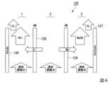
図4に示す3室電気分解装置125はアノード126及びカソード127を有し、アノード126側の陰イオン交換膜128、及びカソード127側の陽イオン交換膜129によってアノード室1、中間室2、カソード室3に分けられている。
3室電気分解装置125においては、電気分解は中間室2のみで行われ、中間室2で発生したイオンが、両側のアノード室1、及びカソード室3に移動する。A three-
In the three-
電気透析濃縮水から電気分解により、アノード室1では、酸性水溶液、カソード室3では、塩基性水溶液が製造される。3室電気分解装置125は、上記2室電気分解装置121とは異なり、酸性水溶液及び塩基性水溶液に塩水が混ざらないというメリットを有する。
なお、3室電気分解装置125におけるアノード126及びカソード127としては、それぞれ2室電気分解装置121におけるアノード122及びカソード123と同様のものが挙げられる。An acidic aqueous solution is produced in the anode chamber 1 and a basic aqueous solution in the
The
電気分解装置120を用いて、例えば、ナトリウムイオン及び塩化物イオンを含む排水を電気分解すると、下記式(1)に示す反応が進行して、水酸化ナトリウム水溶液(アルカリ性水溶液)及び塩酸(酸性水溶液)が得られる。
NaCl+2H2O=NaOH+HCl+H2+1/2O2・・・(1)For example, when wastewater containing sodium ions and chloride ions is electrolyzed using the
NaCl+2H2 O=NaOH+HCl+H2 +1/2O2 (1)
また、アノードが水素ガス拡散電極である電気分解装置120を用いた場合は、アノードでは、下記式(2)に示す水素酸化反応が起こる。また、全反応は下記式(3)に示す通りである。
H2=2H++2e-・・・(2)
NaCl+H2O=NaOH+HCl・・・(3)Further, when the
H2 = 2H+ +2e- (2)
NaCl+H2 O=NaOH+HCl (3)
原料水素ガスはカソードで発生する高純度の電解水素ガスを用いる。塩素発生電位より卑な電位に保持することで塩素発生を抑制することができる。 High-purity electrolytic hydrogen gas generated at the cathode is used as the raw material hydrogen gas. Chlorine generation can be suppressed by maintaining the potential lower than the chlorine generation potential.
電気分解装置120で製造される酸性水溶液(例えば、塩酸)は、第1の循環部13及び排水流入管10を介して、電気透析装置110に供給される排水に循環される。
電気分解装置120で製造される酸性水溶液を、排水に循環させ、排水のpHを調整することができる。
例えば、上述した電気透析装置110に供給される排水が、既に炭酸カルシウムを除去する晶析装置や、重金属を水酸化物として沈殿除去するアルカリ沈殿装置により、処理されている場合もある。その場合、該排水はアルカリ性(pH11以上程度)であるため、電気分解装置120で製造される酸性水溶液を、排水に循環させ、排水のpHを調整することが好ましい。具体的には、排水のpHが10以下となるように調整することが好ましく、排水のpHが3~9となるように調整することがより好ましい。
これにより、1価陰イオン選択透過性イオン交換膜114及び1価陽イオン選択透過性イオン交換膜115の劣化をより防止することができる。The acidic aqueous solution (for example, hydrochloric acid) produced by the
The acidic aqueous solution produced by the
For example, the waste water supplied to the
Thereby, deterioration of the monovalent anion permselective
なお、本明細書において、各種水溶液のpHは、各種水溶液の25℃におけるpHをpHメーター(D74、堀場製作所社製)で測定した値を意味する。 In this specification, the pH of various aqueous solutions means the value obtained by measuring the pH of various aqueous solutions at 25° C. with a pH meter (D74, manufactured by HORIBA, Ltd.).
また、電気分解装置120で製造される酸性水溶液(例えば、塩酸)は、第2の循環部15を介して、電気分解装置120の停止時に、電気分解装置120内を洗浄する際に利用される。なお、電気分解装置120は、該酸性水溶液を貯蔵する貯蔵槽を備えていてもよい。 Further, the acidic aqueous solution (for example, hydrochloric acid) produced by the
なお、図1示す第1の実施形態の酸性水溶液の製造装置の模式図において、酸性水溶液の製造装置100は、上記第2の循環部15を備えているが、備えていなくてもよい。 In addition, in the schematic diagram of the apparatus for producing an acidic aqueous solution of the first embodiment shown in FIG. 1, the apparatus for producing an acidic
また、電気分解装置120は、電気分解装置120で製造されるアルカリ性水溶液を利用するために、他の装置と接続されていてもよい。他の装置としては、例えば、アルカリ性水溶液を利用して、炭酸カルシウムを除去する晶析装置や、重金属を水酸化物として沈殿除去するアルカリ沈殿装置等が挙げられる。 Moreover, the
以上説明した第1の実施形態の酸性水溶液の製造装置100は、上述した電気透析装置110と、電気分解装置120と、第1の循環部13とを備える。排水のpHを調整して、該電気透析装置が有する1価イオン選択透過性イオン交換膜の劣化を防止するために必要な酸性水溶液を、オンサイトで電気分解装置120で製造し、第1の循環部13を介して電気透析装置110で利用することができるため、酸性水溶液を外部から搬送して、貯蔵する必要がなくなり、経済的な負担を大幅に低減することができる。 The acidic aqueous
<第2の実施形態の酸性水溶液の製造装置>
第2の実施形態の酸性水溶液の製造装置は、第1の実施形態の酸性水溶液の製造装置にさらに次亜塩素酸ナトリウム製造装置を備える。すなわち、第2の実施形態の酸性水溶液の製造装置は、電気透析装置と、電気分解装置と、第1の循環部と、次亜塩素酸ナトリウム製造装置とを備える。
第2の実施形態の酸性水溶液の製造装置について、図5を用いて詳細に説明する。<Apparatus for Producing Acidic Aqueous Solution of Second Embodiment>
The acidic aqueous solution manufacturing apparatus of the second embodiment further includes a sodium hypochlorite manufacturing apparatus in addition to the acidic aqueous solution manufacturing apparatus of the first embodiment. That is, the apparatus for producing an acidic aqueous solution of the second embodiment includes an electrodialysis apparatus, an electrolysis apparatus, a first circulation unit, and a sodium hypochlorite production apparatus.
The apparatus for producing an acidic aqueous solution according to the second embodiment will be described in detail with reference to FIG.
図5に示す、第2の実施形態の酸性水溶液の製造装置101は、以下の構成を有する。
排水を供給する排水流入管10が電気透析装置110の電気透析希釈室に接続されている。また、透析用水を供給する透析用水電気透析濃縮室供給管9が電気透析装置110の電気透析濃縮室に接続されている。電気透析装置110の出口側には、第1の電気透析濃縮水供給管11、電気透析希釈水排出管12、及び第2の電気透析濃縮水供給管16が接続されている。電気透析装置110は、電気透析濃縮水供給管11を介して電気分解装置120に接続されている。電気分解装置120出口側には、第1の循環部13、酸性水排出管14、及び第2の循環部15が接続されている。また、電気透析装置110は、第2の電気透析濃縮水供給管16を介して次亜塩素酸ナトリウム製造装置130と接続されている。次亜塩素酸ナトリウム製造装置130の出口側には、次亜塩素酸ナトリウム水溶液排出管17が接続されている。The acidic aqueous
A
次亜塩素酸ナトリウム製造装置130は、電気透析濃縮水の一部を電気分解して、次亜塩素酸ナトリウムを製造する装置である。
次亜塩素酸ナトリウム製造装置130として、具体的には、図6に示す1室電気分解装置131が挙げられる。1室電気分解装置131は、アノード132及びカソード133を備える。
なお、次亜塩素酸ナトリウム製造装置131におけるアノード132及びカソード133としては、それぞれ2室電気分解装置121におけるアノード122及びカソード123と同様のものが挙げられる。The sodium
A specific example of the sodium
As the
次亜塩素酸ナトリウム製造装置130において、下記式(4)に示す反応が起こり、排水中に含まれる塩化物イオンから次亜塩素酸ナトリウムを製造することができる。
2Cl-=Cl2+2e-
2NaOH+Cl2→NaCl+NaClO+H2O・・・(4)In the sodium
2Cl− =Cl2 +2e−
2NaOH+Cl2 →NaCl+NaClO+H2O (4)
上記次亜塩素酸ナトリウムは、例えば、排水処理を行った処理水の消毒剤として利用することができる。そのため、次亜塩素酸ナトリウム水溶液排出管17を排水処理を行った排水を排出する管に接続すれば、該次亜塩素酸ナトリウムをオンサイトで利用することができる。 The above sodium hypochlorite can be used, for example, as a disinfectant for treated water after wastewater treatment. Therefore, if the sodium hypochlorite aqueous
なお、第2の実施形態の酸性水溶液の製造装置101は、透析用水電気透析濃縮室供給管9を備えているが、排水の水質によっては、透析用水電気透析濃縮室供給管9を備えていなくてもよく、電気透析装置110には排水流入管10のみが接続されていてもよい。すなわち、電気透析装置110の電気透析濃縮室及び電気透析希釈室共に排水が供給されるような態様であってもよい。 Although the acidic aqueous
また、第2の実施形態の酸性水溶液の製造装置101は、電気分解装置120で製造される酸性水溶液(例えば、塩酸)を、電気分解装置120内を洗浄するために循環させる、第2の循環部15を備えているが、備えていなくてもよい。 In addition, the acidic aqueous
以上説明した第2の実施形態の酸性水溶液の製造装置101は、上述した第1の実施形態の酸性水溶液の製造装置100の効果に加えて、処理水の消毒剤として用いる次亜塩素酸ナトリウム水溶液をオンサイトで次亜塩素酸ナトリウム製造装置130において製造することができる。また、製造された次亜塩素酸ナトリウム水溶液を処理水に添加することで該次亜塩素酸ナトリウム水溶液を消毒剤として利用することができる。 In addition to the effects of the acidic aqueous
<第3の実施形態の酸性水溶液の製造装置>
第3の実施形態の酸性水溶液の製造装置は、第1の実施形態の酸性水溶液の製造装置にさらに過酸化水素製造装置を備える。すなわち、第2の実施形態の酸性水溶液の製造装置は、電気透析装置と、電気分解装置と、第1の循環部と、過酸化水素製造装置とを備える。
第3の実施形態の酸性水溶液の製造装置について、図7を用いて詳細に説明する。<Apparatus for producing an acidic aqueous solution according to the third embodiment>
The apparatus for producing an acidic aqueous solution according to the third embodiment further includes a hydrogen peroxide producing apparatus in addition to the apparatus for producing an acidic aqueous solution according to the first embodiment. That is, the apparatus for producing an acidic aqueous solution of the second embodiment includes an electrodialysis apparatus, an electrolysis apparatus, a first circulation unit, and a hydrogen peroxide production apparatus.
An apparatus for producing an acidic aqueous solution according to the third embodiment will be described in detail with reference to FIG.
図7に示す、第3の実施形態の酸性水溶液の製造装置102は、以下の構成を有する。
排水を供給する排水流入管10が電気透析装置110の電気透析希釈室に接続されている。また、透析用水を供給する透析用水電気透析濃縮室供給管9が電気透析装置110の電気透析濃縮室に接続されている。電気透析装置110の出口側には、第1の電気透析濃縮水供給管11、電気透析希釈水排出管12、及び第3の電気透析濃縮水供給管18が接続されている。電気透析装置110は、電気透析濃縮水供給管11を介して電気分解装置120に接続されている。電気分解装置120出口側には、第1の循環部13、酸性水排出管14、及び第2の循環部15が接続されている。また、電気透析装置110は、第3の電気透析濃縮水供給管18を介して過酸化水素製造装置140と接続されている。過酸化水素製造装置140の出口側には、過酸化水素排出管19が接続されている。The acidic aqueous
A
過酸化水素製造装置140は、前記電気透析濃縮水の一部を電気分解して、過酸化水素を製造する装置である。 The hydrogen
過酸化水素製造装置140としては、例えば、図8に示すガス拡散電極を有する2室電気分解装置141が挙げられる。
ガス拡散電極を有する2室電気分解装置141は、アノード142及びカソード143を有し、隔膜144によってアノード室145、カソード室146に分けられている。As the hydrogen
A two-
アノード142として、具体的には、上述した電気透析装置110のアノード112と同様のものが挙げられる。 Specifically, the
カソード143として、具体的には、原料である酸素ガスの物質移動に優れた多孔性の酸素ガス拡散電極を用いることが好ましい。
多孔性の酸素ガス拡散電極として、より具体的には、粒径が数10μm程度の黒鉛粉末を触媒とし、フッ素樹脂液を混合したシートをカーボンクロス、カーボンペーパーなどの通気性に優れた伝導性の支持体に、ホットプレスにより固定した、酸素ガス拡散電極が好ましい。Specifically, as the
As a porous oxygen gas diffusion electrode, more specifically, graphite powder with a particle size of about several tens of μm is used as a catalyst, and a sheet mixed with a fluororesin liquid is used as a conductive material with excellent air permeability such as carbon cloth or carbon paper. An oxygen gas diffusion electrode fixed by hot pressing to a support of is preferred.
過酸化水素製造装置140におけるアノード142とカソード143の電極間距離は0.2~5mmが好ましい。
隔膜144としては、上述した2室電気分解装置121における隔膜124と同様のものが挙げられる。The distance between the electrodes of the
The
上述したカソード触媒を形成させたガス拡散電極の背後から酸素を含有するガスを供給しながら電解すると、下記式(5)に示す反応により、過酸化水素(イオン)が製造される。
O2+H2O+2e-=HO2-+OH- ・・・(5)When electrolysis is performed while supplying an oxygen-containing gas from behind the gas diffusion electrode on which the cathode catalyst is formed, hydrogen peroxide (ions) is produced by the reaction represented by the following formula (5).
O2 +H2 O+2e− =HO2− +OH− (5)
上記過酸化水素は、例えば、飲料水製造の最終段階のUV処理工程において併用することで、AOP(促進酸化処理、Advanced Oxidation Process)が進行し、水質の向上に寄与する。また、排水をオゾンにより処理する場合、オゾンによる酸化処理が過度となった際に、例えば、一般的に排水中に含まれる臭化物イオンの酸化により生成する臭素酸の分解にも利用できる。
さらに、次亜塩素酸ナトリウム水溶液による消毒処理を行う場合、過剰な次亜塩素酸ナトリウムを除去する際に、過酸化水素を用いることもできる。
上記処理を行う装置又は該装置により処理を行った処理水の排出管に、過酸化水素排出管19を接続させることにより、上述した過酸化水素製造装置140により製造された過酸化水素を利用することができる。For example, when the hydrogen peroxide is used together in the UV treatment process in the final stage of the production of drinking water, AOP (Advanced Oxidation Process) proceeds and contributes to the improvement of water quality. In the case of treating wastewater with ozone, it can also be used to decompose bromic acid, which is generally generated by oxidation of bromide ions contained in wastewater when the oxidation treatment with ozone becomes excessive.
Furthermore, when performing disinfection treatment with an aqueous sodium hypochlorite solution, hydrogen peroxide can also be used when removing excess sodium hypochlorite.
Hydrogen peroxide produced by the hydrogen
なお、第3の実施形態の酸性水溶液の製造装置102は、透析用水電気透析濃縮室供給管9を備えているが、排水の水質によっては、透析用水電気透析濃縮室供給管9を備えていなくてもよく、電気透析装置110には排水流入管10のみが接続されていてもよい。すなわち、電気透析装置110の電気透析濃縮室及び電気透析希釈室共に排水が供給されるような態様であってもよい。 Although the acidic aqueous
また、第3の実施形態の酸性水溶液の製造装置102は、電気分解装置120で製造される酸性水溶液(例えば、塩酸)を、電気分解装置120内を洗浄するために循環させる、第2の循環部15を備えているが、備えていなくてもよい。 In addition, the acidic aqueous
以上説明した第3の実施形態の酸性水溶液の製造装置102は、上述した第1の実施形態の酸性水溶液の製造装置100の効果に加えて、排水の処理工程において一般的に用いられる過酸化水素をオンサイトで過酸化水素製造装置140において製造することができる。また、製造された過酸化水素を処理水に添加することで該過酸化水素を利用することができる。 In addition to the effects of the acidic aqueous
<第4の実施形態の酸性水溶液の製造装置>
第4の実施形態の酸性水溶液の製造装置は、第1の実施形態の酸性水溶液の製造装置にさらに次亜塩素酸ナトリウム製造装置及び過酸化水素製造装置を備える。すなわち、第4の実施形態の酸性水溶液の製造装置は、電気透析装置と、電気分解装置と、第1の循環部と、次亜塩素酸ナトリウム製造装置と、過酸化水素製造装置とを備える。
第4の実施形態の酸性水溶液の製造装置について、図9を用いて詳細に説明する。<Apparatus for Producing Acidic Aqueous Solution of Fourth Embodiment>
The acidic aqueous solution production apparatus of the fourth embodiment further includes a sodium hypochlorite production apparatus and a hydrogen peroxide production apparatus in addition to the acidic aqueous solution production apparatus of the first embodiment. That is, the acidic aqueous solution production apparatus of the fourth embodiment includes an electrodialysis apparatus, an electrolysis apparatus, a first circulation unit, a sodium hypochlorite production apparatus, and a hydrogen peroxide production apparatus.
The apparatus for producing an acidic aqueous solution according to the fourth embodiment will be described in detail with reference to FIG.
図9に示す、第4の実施形態の酸性水溶液の製造装置103は、以下の構成を有する。
排水を供給する排水流入管10が電気透析装置110の電気透析希釈室に接続されている。また、透析用水を供給する透析用水電気透析濃縮室供給管9が電気透析装置110の電気透析濃縮室に接続されている。電気透析装置110の出口側には、第1の電気透析濃縮水供給管11、電気透析希釈水排出管12、第2の電気透析濃縮水供給管16及び第3の電気透析濃縮水供給管18が接続されている。電気透析装置110は、電気透析濃縮水供給管11を介して電気分解装置120に接続されている。電気分解装置120出口側には、第1の循環部13、酸性水排出管14、及び第2の循環部15が接続されている。また、電気透析装置110は、第2の電気透析濃縮水供給管16を介して次亜塩素酸ナトリウム製造装置130と接続されている。次亜塩素酸ナトリウム製造装置130の出口側には、次亜塩素酸ナトリウム水溶液排出管17が接続されている。さらに電気透析装置110は、第3の電気透析濃縮水供給管18を介して過酸化水素製造装置140と接続されている。過酸化水素製造装置140の出口側には、過酸化水素排出管19が接続されている。The acidic aqueous
A
なお、第4の実施形態の酸性水溶液の製造装置103は、透析用水電気透析濃縮室供給管9を備えているが、排水の水質によっては、透析用水電気透析濃縮室供給管9を備えていなくてもよく、電気透析装置110には排水流入管10のみが接続されていてもよい。すなわち、電気透析装置110の電気透析濃縮室及び電気透析希釈室共に排水が供給されるような態様であってもよい。 Although the acidic aqueous
また、第4の実施形態の酸性水溶液の製造装置103は、電気分解装置120で製造される酸性水溶液(例えば、塩酸)を、電気分解装置120内を洗浄するために循環させる、第2の循環部15を備えているが、備えていなくてもよい。 Further, the acidic aqueous
以上説明した第4の実施形態の酸性水溶液の製造装置103は、上述した第1の実施形態の酸性水溶液の製造装置100の効果に加えて、処理水の消毒剤として用いる次亜塩素酸ナトリウム水溶液及び排水の処理工程において一般的に用いられる過酸化水素をオンサイトで製造することができる。また、製造された次亜塩素酸ナトリウム水溶液及び過酸化水素をオンサイトで利用することができる。 In addition to the effects of the acidic aqueous
(酸性水溶液の製造方法)
本発明の第2の態様は、塩化物イオン及びアルカリ金属イオンを含む排水から、酸性水溶液を製造する酸性水溶液の製造方法であって、前記排水を電気透析処理により電気透析濃縮水と電気透析希釈水とに分離する電気透析工程と、前記電気透析濃縮水を電気分解して、酸性水溶液を製造する電気分解工程と、前記酸性水溶液の少なくとも一部を、前記電気透析工程に供給される前記排水に循環させる第1の循環工程とを有する、酸性水溶液の製造方法である。(Method for producing acidic aqueous solution)
A second aspect of the present invention is a method for producing an acidic aqueous solution from wastewater containing chloride ions and alkali metal ions, wherein the wastewater is subjected to electrodialysis treatment to electrodialyze concentrated water and electrodialysis dilution. an electrodialysis step of separating into water, an electrolysis step of electrolyzing the electrodialysis concentrated water to produce an acidic aqueous solution, and at least part of the acidic aqueous solution being supplied to the electrodialysis step. A method for producing an acidic aqueous solution, comprising a first circulation step of circulating to.
<第1の実施形態の酸性水溶液の製造方法>
第1の実施形態の酸性水溶液の製造方法は、電気透析工程210と、電気分解工程220と、第1の循環工程とを有する。
第1の実施形態の酸性水溶液の製造方法の模式図は、図10に示す通りである。<Method for Producing Acidic Aqueous Solution of First Embodiment>
The method for producing an acidic aqueous solution of the first embodiment has an
A schematic diagram of the method for producing an acidic aqueous solution according to the first embodiment is shown in FIG.
[電気透析工程]
電気透析工程210は、塩化物イオン及びアルカリ金属イオンを含む排水を電気透析処理により電気透析濃縮水と電気透析希釈水とに分離する工程である。
具体的には、上述した電気透析装置(図2)のように多数の電気透析膜を配列し、交互に形成した電気透析濃縮室と電気透析希釈室とを備える電気透析装置に排水を供給して、通電することにより濃縮室には各種イオン成分が高濃度に含まれる電気透析濃縮水を得ることができ、希釈室には各種イオン成分が低濃度に含まれる電気透析希釈水を得ることができる。[Electrodialysis step]
The
Specifically, wastewater is supplied to an electrodialysis apparatus having a large number of electrodialysis membranes arranged in the same manner as the above-described electrodialysis apparatus (FIG. 2) and alternately formed electrodialysis concentration chambers and electrodialysis dilution chambers. By energizing the concentrating chamber, electrodialysis concentrated water containing various ion components at a high concentration can be obtained, and electrodialysis diluting water containing various ion components at a low concentration can be obtained in the dilution chamber. can.
電気透析条件としては、温度は25~60℃が好ましく、電流密度としては1~10A/dm2が好ましい。As electrodialysis conditions, the temperature is preferably 25 to 60° C., and the current density is preferably 1 to 10 A/dm2 .
本実施形態の酸性水溶液の製造方法は、電気透析工程210を有することにより、排水中の塩化物イオンの濃度を高くすることができるため、後述する電気分解工程において、酸性水溶液をより効率よく製造できる。また、電気分解工程に用いる電気分解装置に付着しやすい多価イオンを予め除去することができる。 Since the method for producing an acidic aqueous solution of the present embodiment includes the
[電気分解工程]
電気分解工程220は、排水の一部を電気分解して酸性水溶液とアルカリ性水溶液とを得る工程である。
具体的には、電子伝導性を有する1対の電極(陽極;アノード、陰極;カソード)と、イオン伝導性を有する電解質に、電圧をかけることでアノードでは酸化反応、カソードでは還元反応を起こして、酸性水溶液とアルカリ性水溶液とを得る方法である。[Electrolysis process]
The
Specifically, by applying a voltage to a pair of electrodes (anode; anode, cathode; cathode) having electronic conductivity and an electrolyte having ionic conductivity, an oxidation reaction occurs at the anode and a reduction reaction occurs at the cathode. , to obtain an acidic aqueous solution and an alkaline aqueous solution.
電気分解工程220は、例えば、上述した2室電気分解装置(図3)及び3室電気分解装置(図4)を用いて行うことができる。 The
電気分解工程220において、例えば、ナトリウムイオン及び塩化物イオンを含む排水を電気分解すると、下記式(6)に示す反応が進行して、水酸化ナトリウム水溶液(アルカリ性水溶液)及び塩酸(酸性水溶液)が得られる。
NaCl+2H2O=NaOH+HCl+H2+1/2O2・・・(6)In the
NaCl+2H2O =NaOH+HCl+H2 +1/2O2 (6)
例えば、後述する2室電気分解装置(図3)では、酸性水溶液としては、塩酸と塩水との混合物、アルカリ性水溶液としては、水酸化ナトリウムと塩水との混合物とが得られる。
一方、後述する3室電気分解装置(図4)では、カソード室には水酸化ナトリウム水溶液、アノード室には塩酸が得られる。
この反応で得られる塩酸は、上述した電気透析工程210に供給する排水に混合され、pHを調整させるために用いられる。For example, in a two-chamber electrolyzer (FIG. 3), which will be described later, a mixture of hydrochloric acid and salt water is obtained as the acidic aqueous solution, and a mixture of sodium hydroxide and salt water is obtained as the alkaline aqueous solution.
On the other hand, in the three-chamber electrolyzer (FIG. 4) described later, an aqueous sodium hydroxide solution is obtained in the cathode chamber and hydrochloric acid is obtained in the anode chamber.
The hydrochloric acid obtained by this reaction is mixed with the waste water supplied to the
また、アノードが水素ガス拡散電極である電気分解装置を用いた場合は、アノードでは下記式(7)に示す水素酸化反応が起こる。また、全反応は下記式(8)に示す通りである。
H2=2H++2e-・・・(7)
NaCl+H2O=NaOH+HCl・・・(8)Further, when an electrolyzer whose anode is a hydrogen gas diffusion electrode is used, a hydrogen oxidation reaction represented by the following formula (7) occurs at the anode. Also, the overall reaction is as shown in the following formula (8).
H2 =2H+ +2e− (7)
NaCl+H2 O=NaOH+HCl (8)
原料水素ガスはカソードで発生する高純度の電解水素ガスを用いる。塩素発生電位より卑な電位に保持することで塩素発生を抑制することができる。 High-purity electrolytic hydrogen gas generated at the cathode is used as the raw material hydrogen gas. Chlorine generation can be suppressed by maintaining the potential lower than the chlorine generation potential.
電気分解工程220において、上述した水素酸化反応によって、酸性水溶液とアルカリ性水溶液とを製造することにより、塩素の発生をより抑制することができる。 In the
[第1の循環工程]
第1の循環工程は、電気分解工程220によって製造される酸性水溶液の少なくとも一部を、電気透析工程に供給される排水に循環させる工程である。
電気透析工程に供給される排水は、電気分解工程220で得られる酸性水溶液により、該排水のpHが調整されている。
例えば、上述した電気透析工程210に供給される排水が、既に炭酸カルシウムを除去する晶析装置や、重金属を水酸化物として沈殿除去するアルカリ沈殿装置により、処理されている場合もある。その場合、該排水はアルカリ性(pH11以上程度)であるため、電気分解工程で製造される酸性水溶液を、排水に循環させ、排水のpHを調整することが好ましい。具体的には、排水のpHが10以下となるように調整することが好ましく、排水のpHが3~9となるように調整することがより好ましい。
これにより、電気透析工程に用いられる電気透析装置が有する1価陰イオン選択透過性イオン交換膜及び1価陽イオン選択透過性イオン交換膜の劣化をより防止することができる。[First circulation step]
The first circulation step is a step of circulating at least a portion of the acidic aqueous solution produced by the
The waste water supplied to the electrodialysis process has its pH adjusted by the acidic aqueous solution obtained in the
For example, the wastewater supplied to the
This makes it possible to further prevent deterioration of the monovalent anion permselective ion exchange membrane and the monovalent cation permselective ion exchange membrane of the electrodialyzer used in the electrodialysis step.
[洗浄工程]
本実施形態の酸性水溶液の製造方法は、洗浄工程を有していてもよい。洗浄工程は、上記酸性水溶液の少なくとも一部を用いて、上述した電気分解工程220で使用する装置(電気分解装置)を洗浄する工程である。電気分解装置の長時間の連続稼働によって、硬度成分が電気分解装置の装置内の隔膜やカソードに析出して、電気分解装置の性能低下を招く。そのため、間欠的に電気分解装置を停止して、電気分解工程220で得られた酸性水溶液で洗浄することが好ましい。洗浄を行う頻度は、水質、運転条件にもよるが、数時間から数十時間ごとに、数十分から数時間実施することが好ましい。[Washing process]
The method for producing an acidic aqueous solution of the present embodiment may have a washing step. The cleaning step is a step of cleaning the device (electrolysis device) used in the above-described
以上説明した第1の実施形態の酸性水溶液の製造装置は、上述した電気透析工程と、電気分解工程220と、第1の循環工程とを有する。排水のpHを調整して、該電気透析工程で用いる1価イオン選択透過性イオン交換膜の劣化を防止するために必要な酸性水溶液を、オンサイトで電気分解工程220で製造し、第1の循環工程によって該電気透析工程で利用することができるため、酸性水溶液を外部から搬送して、貯蔵する必要がなくなり、経済的な負担を大幅に低減することができる。 The apparatus for producing an acidic aqueous solution of the first embodiment described above has the above-described electrodialysis process,
<第2の実施形態の酸性水溶液の製造方法>
第2の実施形態の酸性水溶液の製造方法は、電気透析工程210と、電気分解工程220と、第1の循環工程と、次亜塩素酸ナトリウム製造工程230とを有する。
第2の実施形態の酸性水溶液の製造方法の模式図は、図11に示す通りである。<Method for Producing Acidic Aqueous Solution of Second Embodiment>
The method for producing an acidic aqueous solution of the second embodiment has an
A schematic diagram of the method for producing an acidic aqueous solution according to the second embodiment is shown in FIG.
[次亜塩素酸ナトリウム製造工程]
次亜塩素酸ナトリウム製造工程230は、電気透析濃縮水の一部を電気分解して、次亜塩素酸ナトリウム水溶液を製造する工程である。
アノード触媒を適宜選択することにより、下記式(4)のような反応が起こり、排水中に含まれる塩化物イオンから次亜塩素酸ナトリウムを製造することができる。
2Cl-=Cl2+2e-
2NaOH+Cl2→NaCl+NaClO+H2O・・・(4)[Sodium hypochlorite manufacturing process]
The sodium
By appropriately selecting an anode catalyst, a reaction such as the following formula (4) occurs, and sodium hypochlorite can be produced from chloride ions contained in the waste water.
2Cl− =Cl2 +2e−
2NaOH+Cl2 →NaCl+NaClO+H2O (4)
該次亜塩素酸ナトリウムは、処理水の消毒剤として利用することができる。
そのため、第2の実施形態の酸性水溶液の製造方法では、上述した第1の実施形態の酸性水溶液の製造方法の効果に加えて、処理水の消毒剤として用いる次亜塩素酸ナトリウム水溶液をオンサイトで次亜塩素酸ナトリウム製造工程において製造し、処理水に添加することで該次亜塩素酸ナトリウム水溶液を消毒剤として利用することができる。
次亜塩素酸成分はアルカリ域では次亜塩素酸イオンとして、酸性域では次亜塩素酸として安定に存在し、電気分解する溶液のpHを変えることでいずれも製造することができる。殺菌力は後者においてより高まることが知られている。本発明における次亜塩素酸ナトリウムは、それらを総称している。The sodium hypochlorite can be used as a disinfectant for treated water.
Therefore, in the method for producing an acidic aqueous solution of the second embodiment, in addition to the effects of the above-described method for producing an acidic aqueous solution of the first embodiment, an aqueous sodium hypochlorite solution used as a disinfectant for treated water is provided on-site. The sodium hypochlorite aqueous solution can be used as a disinfectant by producing it in the sodium hypochlorite production process and adding it to the treated water.
The hypochlorous acid component stably exists as hypochlorous acid ions in an alkaline region and as hypochlorous acid in an acidic region, and both can be produced by changing the pH of the electrolyzed solution. It is known that the bactericidal activity is higher in the latter. Sodium hypochlorite in the present invention is a generic term for them.
<第3の実施形態の酸性水溶液の製造方法>
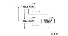
第3の実施形態の酸性水溶液の製造方法は、電気透析工程210と、電気分解工程220と、第1の循環工程と、過酸化水素製造工程240とを有する。
第3の実施形態の酸性水溶液の製造方法の模式図は、図12に示す通りである。<Method for Producing Acidic Aqueous Solution of Third Embodiment>
The method for producing an acidic aqueous solution of the third embodiment has an
A schematic diagram of the method for producing an acidic aqueous solution according to the third embodiment is shown in FIG.
[過酸化水素製造工程]
過酸化水素製造工程240、電気透析濃縮水の一部を電気分解して、過酸化水素を製造する工程である。[Hydrogen peroxide production process]
Hydrogen
過酸化水素製造工程は、例えば、上述した過酸化水素製造装置を用いて行うことができる。
過酸化水素は、例えば、飲料水製造の最終段階のUV処理工程において併用することで、AOP(促進酸化処理、Advanced Oxidation Process)が進行し、水質の向上に寄与する。また、排水をオゾンにより処理する場合、オゾンによる酸化処理が過度となった際に、例えば、排水中に含まれる臭化物イオンの酸化により生成する臭素酸の分解にも利用できる。
さらに、次亜塩素酸ナトリウム水溶液による消毒処理を行う場合、過剰な次亜塩素酸ナトリウムを除去する際に、過酸化水素を用いることもできる。The hydrogen peroxide production step can be performed using, for example, the hydrogen peroxide production apparatus described above.
Hydrogen peroxide, for example, is used together in the UV treatment process in the final stage of the production of drinking water, thereby promoting AOP (Advanced Oxidation Process) and contributing to improvement of water quality. In the case of treating waste water with ozone, it can also be used to decompose bromic acid, which is generated by oxidation of bromide ions contained in the waste water when the oxidation treatment with ozone becomes excessive.
Furthermore, when performing disinfection treatment with an aqueous sodium hypochlorite solution, hydrogen peroxide can also be used when removing excess sodium hypochlorite.
以上説明した第3の実施形態の酸性水溶液の製造方法は、上述した第1の実施形態の酸性水溶液の製造方法の効果に加えて、排水の処理工程において一般的に用いられる過酸化水素をオンサイトで過酸化水素製造装置において製造することができる。また、製造された過酸化水素を処理水に添加することで該過酸化水素を利用することができる。 In addition to the effects of the method for producing an acidic aqueous solution according to the first embodiment, the method for producing an acidic aqueous solution according to the third embodiment described above has the effect of turning on hydrogen peroxide, which is generally used in the wastewater treatment process. It can be produced on-site in a hydrogen peroxide production unit. Further, by adding the produced hydrogen peroxide to the treated water, the hydrogen peroxide can be utilized.
<第4の実施形態の酸性水溶液の製造方法>
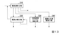
第4の実施形態の酸性水溶液の製造方法は、電気透析工程210と、電気分解工程220と、第1の循環工程と、次亜塩素酸ナトリウム製造工程230と、過酸化水素製造工程240とを有する。
第4の実施形態の酸性水溶液の製造方法の模式図は、図13に示す通りである。<Method for Producing Acidic Aqueous Solution of Fourth Embodiment>
The method for producing an acidic aqueous solution of the fourth embodiment includes an
A schematic diagram of the method for producing an acidic aqueous solution according to the fourth embodiment is shown in FIG.
第4の実施形態の酸性水溶液の製造方法は、上述した第1の実施形態の酸性水溶液の製造方法の効果に加えて、処理水の消毒剤として用いる次亜塩素酸ナトリウム水溶液及び排水の処理工程において一般的に用いられる過酸化水素をオンサイトで製造することができる。また、製造された次亜塩素酸ナトリウム水溶液及び過酸化水素をオンサイトで利用することができる。 The method for producing an acidic aqueous solution of the fourth embodiment has the effects of the method for producing an acidic aqueous solution of the first embodiment described above, in addition to the sodium hypochlorite aqueous solution used as a disinfectant for treated water and the step of treating wastewater. Hydrogen peroxide, which is commonly used in , can be produced on-site. Moreover, the sodium hypochlorite aqueous solution and hydrogen peroxide which were manufactured can be utilized on-site.
以下、実施例により本発明をさらに詳細に説明するが、本発明はこれらの例によって限定されるものではない。 EXAMPLES The present invention will be described in more detail below with reference to examples, but the present invention is not limited to these examples.
・被処理水について
被処理水としては、表1に示す各種イオン成分(ナトリウムイオン、カルシウムイオン、マグネシウムイオン、塩化物イオン、重炭酸イオン及びシリカ)を含む試験用水(模擬排水)を用いて各例の酸性水溶液の製造を行った。・Water to be treated As water to be treated, test water (simulated wastewater) containing various ion components (sodium ion, calcium ion, magnesium ion, chloride ion, bicarbonate ion and silica) shown in Table 1 was used. Preparation of an acidic aqueous solution of the example was carried out.
<実施例1>
図1に示す電気透析装置と、電気分解装置とを備える酸性水溶液の製造装置を用いて、酸性水溶液の製造を行った。<Example 1>
An acidic aqueous solution was produced using an acidic aqueous solution producing apparatus including an electrodialysis apparatus and an electrolyzer shown in FIG.
[電気透析工程]
1価イオン選択透過性イオン交換膜を組み込んだ小型の電気透析セル(アストム社製S3、濃縮室数10区画、電極面積55cm2)に、該電気透析セルの希釈室には、8Lの試験用水(後述する電気分解工程で得られる塩酸を使用してpHを6.6に調整した)、該電気透析セルの濃縮室には、0.5Lの水道水を満たし、各室の流量を5mL/minに固定して、電圧10Vを与えて電気透析工程を行った。
その結果表1に示す、電気透析濃縮水、電気透析希釈水が得られた。なお、電流値は0.25A程度であった。[Electrodialysis step]
A small electrodialysis cell (ASTOM S3, 10 concentrating chambers, electrode area 55 cm2 ) incorporating a monovalent ion selective permeable ion exchange membrane was charged with 8 L of test water in the dilution chamber of the electrodialysis cell. (The pH was adjusted to 6.6 using hydrochloric acid obtained in the electrolysis step described below), the concentration chambers of the electrodialysis cell were filled with 0.5 L of tap water, and the flow rate of each chamber was 5 mL/ The electrodialysis step was performed by fixing the voltage to min and applying a voltage of 10V.
As a result, electrodialysis concentrated water and electrodialysis diluted water shown in Table 1 were obtained. Incidentally, the current value was about 0.25A.
[電気分解工程]
電気分解装置としては、陽極(アノード)としてPtとIr酸化物からなる触媒を形成したTiメッシュと、陰極(カソード)としてNiメッシュと、隔膜としてY9201(隔膜:ユアサメンブレンシステム社)とを備え、電極間距離を2mmの隔膜を有する2室電気分解セル(電解面積は10cm2)を用いた。
上記電気透析濃縮水を2室電気分解セルのアノード室に流量5mL/minで供給し、上記電気透析濃縮水を2室電気分解セルのカソード室に流量2.5mL/minで供給した。電流密度5A/dm2で電気分解を行った。セル電圧は6Vであった。
その結果、2室電気分解セルのアノード室には、表1で酸性水溶液として示す、0.7g/Lの塩酸が得られた(pH1.7)。また、2室電気分解セルのカソード室には、表1でアルカリ性水溶液として示す、4g/Lの水酸化ナトリウム水溶液、及び2.5g/Lの炭酸ナトリウム水溶液が得られた(pH12.8)。[Electrolysis process]
The electrolysis apparatus includes a Ti mesh formed with a catalyst made of Pt and Ir oxides as an anode, a Ni mesh as a cathode, and a diaphragm Y9201 (diaphragm: Yuasa Membrane System Co., Ltd.). A two-chamber electrolysis cell (electrolysis area: 10 cm2 ) having a diaphragm with an inter-electrode distance of 2 mm was used.
The electrodialysis concentrated water was supplied to the anode chamber of the two-compartment electrolysis cell at a flow rate of 5 mL/min, and the electrodialysis concentrated water was supplied to the cathode chamber of the two-compartment electrolysis cell at a flow rate of 2.5 mL/min. Electrolysis was performed at a current density of 5 A/dm2 . The cell voltage was 6V.
As a result, 0.7 g/L of hydrochloric acid (pH 1.7) was obtained in the anode compartment of the two-compartment electrolysis cell, shown in Table 1 as an acidic aqueous solution. Also, in the cathode chamber of the two-compartment electrolysis cell, a 4 g/L sodium hydroxide aqueous solution and a 2.5 g/L sodium carbonate aqueous solution, which are shown as alkaline aqueous solutions in Table 1, were obtained (pH 12.8).
[原料水及び各種処理水のpHの測定方法]
表1に示す原料水及び各種処理水のpHは、25℃のpHをpHメーター(D74、堀場製作所社製)で測定した値である。[Method for measuring pH of raw water and various treated waters]
The pH values of raw water and various treated waters shown in Table 1 are values measured at 25° C. with a pH meter (D74, manufactured by Horiba Ltd.).
[各種イオン成分の含有量の測定方法]
表1に示す原料水及び各種処理水(電気透析濃縮水、電気透析希釈水、酸性水溶液、アルカリ性水溶液)の各種イオン成分の濃度の分析方法は、陽イオンの濃度は、アルゴンガスのICPを光源とする発光分光分析装置(ICP-AES;SPS5520、セイコーインスツル社製)を用いて測定した値である。
一方、陰イオンの濃度は、イオンクロマトグラフ分析装置(ICA-2000;東亜ディーケーケー社製)を用いて測定したである。[Method for measuring content of various ion components]
The analysis method of the concentration of various ion components in the raw water and various treated waters (electrodialysis concentrated water, electrodialysis diluted water, acidic aqueous solution, alkaline aqueous solution) shown in Table 1 is as follows. It is a value measured using an emission spectrometer (ICP-AES; SPS5520, manufactured by Seiko Instruments Inc.).
On the other hand, the concentration of anions was measured using an ion chromatograph analyzer (ICA-2000; manufactured by Toa DKK Co., Ltd.).
[塩酸、水酸化ナトリウム水溶液及び炭酸ナトリウム水溶液の生成量の測定方法]
塩酸は濃度が既知の水酸化ナトリウム水溶液により定量した。水酸化ナトリウム水溶液、炭酸ナトリウム水溶液は濃度が既知の塩酸による2段滴定によりそれぞれ定量した。[Method for measuring amounts of hydrochloric acid, aqueous sodium hydroxide solution, and aqueous sodium carbonate solution]
Hydrochloric acid was quantified using an aqueous sodium hydroxide solution with a known concentration. An aqueous sodium hydroxide solution and an aqueous sodium carbonate solution were quantified by two-step titration with hydrochloric acid of known concentration.

<実施例2>
電気分解装置(2室電気分解セル)の陽極(アノード)として、Pt/C粉末触媒とフッ素樹脂液を混合した触媒層をカーボンペーパー上に1mg/cm2の量にてホットプレスにより固定した水素ガス拡散電極を用い、アノードの裏側に形成されたガス室に、電気分解反応を行う理論混合量より1.2倍過剰な水素ガスを供給したこと以外は、実施例1と同様の方法により酸性水溶液の製造を行った。得られた塩酸及び水酸化ナトリウムの生成量は実施例1と同程度であったが、遊離塩素は発生しなかった。<Example 2>
As the anode of the electrolysis device (two-chamber electrolysis cell), a catalyst layer of a mixture of Pt/C powder catalyst and fluororesin liquid was fixed on carbon paper in an amount of 1 mg/cm2 by hot pressing. Acidification was performed in the same manner as in Example 1, except that a gas diffusion electrode was used and hydrogen gas was supplied to the gas chamber formed on the back side of the anode in an excess of 1.2 times the theoretical mixing amount for electrolysis reaction. An aqueous solution was produced. The amounts of hydrochloric acid and sodium hydroxide obtained were about the same as in Example 1, but no free chlorine was generated.
<実施例3>
図7に示す電気透析装置と、電気分解装置と、過酸化水素製造装置を備える酸性水溶液の製造装置を用いて、酸性水溶液の製造を行った。
電気透析装置及び電気透析工程、並びに、電気分解装置及び電気分解工程は、実施例1と同様であり、2室電気分解セルのアノード室には0.7g/Lの塩酸が得られた(pH1.7)。また、2室電気分解セルのカソード室には、4g/Lの水酸化ナトリウム、2.5g/Lの炭酸ナトリウムが得られた(pH12.8)。<Example 3>
An acidic aqueous solution was produced using an acidic aqueous solution production apparatus including an electrodialysis apparatus, an electrolysis apparatus, and a hydrogen peroxide production apparatus shown in FIG.
The electrodialysis device and electrodialysis process, and the electrolysis device and electrolysis process were the same as in Example 1, and 0.7 g/L of hydrochloric acid was obtained in the anode chamber of the two-compartment electrolysis cell (pH 1 .7). Also, 4 g/L of sodium hydroxide and 2.5 g/L of sodium carbonate were obtained in the cathode compartment of the two-compartment electrolytic cell (pH 12.8).
[過酸化水素製造工程]
過酸化水素製造装置としては、陽極(アノード)としてPtとIr酸化物からなる触媒を形成したTiメッシュと、陰極(カソード)として黒鉛粉末触媒とフッ素樹脂液を混合した触媒層をカーボンペーパー上に10mg/cm2の量にてホットプレスにより固定した酸素ガス拡散電極と、隔膜としてY9201(隔膜:ユアサメンブレンシステム社)とを備え、電極間距離を2mmの隔膜を有する2室電気分解セル(電解面積は10cm2)を用いた。
上記電気透析濃縮水を2室電気分解セルのアノード室に流量5mL/minで供給し、上記電気透析濃縮水を2室電気分解セルのカソード室に流量2.5mL/minで供給した。電流密度5A/dm2で電気分解を行った。セル電圧は5.5Vであった。
その結果、1.1g/L(H2O2として)の過酸化水素が得られた。[Hydrogen peroxide production process]
As a hydrogen peroxide production apparatus, a Ti mesh formed with a catalyst composed of Pt and Ir oxides as an anode and a catalyst layer of a mixture of graphite powder catalyst and fluororesin liquid as a cathode are placed on carbon paper. Atwo -chamber electrolysis cell (electrolytic The area used was 10 cm2 ).
The electrodialysis concentrated water was supplied to the anode chamber of the two-compartment electrolysis cell at a flow rate of 5 mL/min, and the electrodialysis concentrated water was supplied to the cathode chamber of the two-compartment electrolysis cell at a flow rate of 2.5 mL/min. Electrolysis was performed at a current density of 5 A/dm2 . The cell voltage was 5.5V.
As a result, 1.1 g/L (as H2 O2 ) of hydrogen peroxide was obtained.
[過酸化水素の生成量の測定方法]
過酸化水素水溶液に硫酸チタンを加えることにより、過酸化水素とチタンとの錯化合物を形成し、該錯化合物のUV吸収スペクトルを吸光度として、島津製作所社製のUV-2550により測定することにより、過酸化水素の生成量を求めた。[Method for measuring the amount of hydrogen peroxide produced]
By adding titanium sulfate to an aqueous hydrogen peroxide solution, a complex compound of hydrogen peroxide and titanium is formed, and the UV absorption spectrum of the complex compound is measured as absorbance with UV-2550 manufactured by Shimadzu Corporation. The amount of hydrogen peroxide produced was determined.
なお、pH、酸性水溶液及びアルカリ性水溶液の生成量の測定方法は上述した実施例1の測定方法と同様である。 The methods for measuring the pH and the amounts of acidic aqueous solution and alkaline aqueous solution produced are the same as those used in Example 1 described above.
<比較例1>
1価イオン選択透過性イオン交換膜の代わりに1価イオン選択透過性のない公知のイオン交換膜を組み込んだ小型の電気透析セル(アストム社製S3、濃縮室数10区画、電極面積55cm2)を用いたこと以外は、実施例1と同様の方法で酸性水溶液の製造を行った。
その結果、セル電圧が急激に増加し、電気分解を継続することができなかった。<Comparative Example 1>
A small electrodialysis cell (ASTOM S3, 10 concentrating compartments, electrode area 55 cm2 ) incorporating a known ion exchange membrane without monovalent ion selective permeability instead of the monovalent ion selective permeability ion exchange membrane. An acidic aqueous solution was produced in the same manner as in Example 1, except that the was used.
As a result, the cell voltage abruptly increased, and the electrolysis could not be continued.
実施例1及び2では、電気透析装置に供給する排水のpHを調整するための酸性水溶液をオンサイトで排水から電気分解装置で製造できることが確認できる。
さらに、実施例3では、該酸性水溶液に加えて、排水から過酸化水素をオンサイトで製造できることが確認できる。In Examples 1 and 2, it can be confirmed that an acidic aqueous solution for adjusting the pH of the waste water to be supplied to the electrodialysis device can be produced on-site from the waste water by the electrolyzer.
Furthermore, in Example 3, it can be confirmed that in addition to the acidic aqueous solution, hydrogen peroxide can be produced on-site from waste water.
一方で、比較例1の1価イオン選択透過性のないイオン交換膜を有する電気透析装置を用いた場合、カソード及び1価イオン選択透過性のないイオン交換膜に多量のカルシウム、マグネシウム成分が析出してしまい、酸性水溶液を継続して得ることはできないことが確認できる。 On the other hand, when the electrodialysis apparatus having the ion exchange membrane without monovalent ion selective permeability of Comparative Example 1 was used, a large amount of calcium and magnesium components were deposited on the cathode and the ion exchange membrane without monovalent ion selective permeability. It can be confirmed that the acidic aqueous solution cannot be obtained continuously.
以上より、本実施形態の酸性水溶液の製造装置及び該装置を用いた酸性水溶液の製造方法によれば、排水処理のプロセスで使用する酸性水溶液をオンサイトで製造、利用することができ、経済的な負担を大幅に低減することができることが確認できる。 As described above, according to the apparatus for producing an acidic aqueous solution of the present embodiment and the method for producing an acidic aqueous solution using the apparatus, the acidic aqueous solution used in the wastewater treatment process can be produced and used on-site, which is economical. It can be confirmed that the burden can be greatly reduced.
100、101、102、103・・・酸性水溶液の製造装置
110、111・・・電気透析装置
120・・・電気分解装置
13・・・第1の循環部
121・・・2室電気分解装置
125・・・3室電気分解装置
130、131・・・次亜塩素酸ナトリウム製造装置
140、141・・・過酸化水素製造装置
210・・・電気透析工程
220・・・電気分解工程
230・・・次亜塩素酸ナトリウム製造工程
240・・・過酸化水素製造工程DESCRIPTION OF
Claims (8)
Translated fromJapanese1価イオン選択透過性イオン交換膜を有し、前記排水を電気透析処理により電気透析濃縮水と電気透析希釈水とに分離する電気透析装置と、
前記電気透析濃縮水を電気分解して、酸性水溶液を製造する電気分解装置と、
前記酸性水溶液の少なくとも一部を、前記電気透析装置に供給される前記排水に循環させる第1の循環部とを備え、
前記1価イオン選択透過性イオン交換膜における陽イオン交換膜は、メタフェノールスルホン酸-フェノール樹脂、又はスチレン-ジビニルベンゼン共重合体をスルホン化反応させた樹脂であり、その樹脂表面にポリエチレンイミンを含むカチオン性高分子電解質を形成したものであり、
前記1価イオン選択透過性イオン交換膜における陰イオン交換膜は、メタフェニレンジアミン-フェノール系縮合樹脂、又はスチレン-ジビニルベンゼン共重合体をアミノ化反応させた樹脂であり、
さらに、前記酸性水溶液の少なくとも一部を前記電気分解装置に循環させる第2の循環部を備える、酸性水溶液の製造装置。An acidic aqueous solution producing apparatus for producing an acidic aqueous solution from waste water containing chloride ions and alkali metal ions,
an electrodialysis apparatus having a monovalent ion permselective ion exchange membrane and separating the wastewater into electrodialysis concentrated water and electrodialysis diluted water by electrodialysis treatment;
an electrolyzer that electrolyzes the electrodialysis concentrated water to produce an acidic aqueous solution;
a first circulation unit that circulates at least part of the acidic aqueous solution to the waste water supplied to the electrodialysis device;
The cation exchange membrane in the monovalent ion permselective ion exchange membrane is a resin obtained by subjecting metaphenolsulfonic acid-phenol resin or styrene-divinylbenzene copolymer to a sulfonation reaction, and polyethylenimine is added to the surface of the resin. Forming a cationic polyelectrolyte containing
The anion exchange membrane in the monovalent ion permselective ion exchange membrane is a metaphenylenediamine-phenol-based condensation resin or a resin obtained by subjecting a styrene-divinylbenzene copolymer to an amination reaction,
An apparatus for producing an acidic aqueous solution, further comprising a second circulation unit that circulates at least part of the acidic aqueous solution to the electrolyzer.
1価イオン選択透過性イオン交換膜を有する電気透析装置を用いて、前記排水を電気透析処理により電気透析濃縮水と電気透析希釈水とに分離する電気透析工程と、
前記電気透析濃縮水を電気分解して、酸性水溶液を製造する電気分解工程と、
前記酸性水溶液の少なくとも一部を、前記電気透析工程に供給される前記排水に循環させる第1の循環工程とを有し、
前記1価イオン選択透過性イオン交換膜における陽イオン交換膜は、メタフェノールスルホン酸-フェノール樹脂、又はスチレン-ジビニルベンゼン共重合体をスルホン化反応させた樹脂であり、その樹脂表面にポリエチレンイミンを含むカチオン性高分子電解質を形成したものであり、
前記1価イオン選択透過性イオン交換膜における陰イオン交換膜は、メタフェニレンジアミン-フェノール系縮合樹脂、又はスチレン-ジビニルベンゼン共重合体をアミノ化反応させた樹脂であり、
さらに、前記酸性水溶液の少なくとも一部を前記電気分解工程で用いる第2の循環工程を有する、酸性水溶液の製造方法。A method for producing an acidic aqueous solution from wastewater containing chloride ions and alkali metal ions, comprising:
An electrodialysis step of separating the wastewater into electrodialysis concentrated water and electrodialysis diluted water by electrodialysis using an electrodialysis device having a monovalent ion permselective ion exchange membrane ;
an electrolysis step of electrolyzing the electrodialysis concentrated water to produce an acidic aqueous solution;
a first circulation step of circulating at least part of the acidic aqueous solution to the waste water supplied to the electrodialysis step;
The cation exchange membrane in the monovalent ion permselective ion exchange membrane is a resin obtained by subjecting metaphenolsulfonic acid-phenol resin or styrene-divinylbenzene copolymer to a sulfonation reaction, and polyethylenimine is added to the surface of the resin. Forming a cationic polyelectrolyte containing
The anion exchange membrane in the monovalent ion permselective ion exchange membrane is a metaphenylenediamine-phenol-based condensation resin or a resin obtained by subjecting a styrene-divinylbenzene copolymer to an amination reaction,
A method for producing an acidic aqueous solution, further comprising a second circulation step of using at least part of the acidic aqueous solution in the electrolysis step.
Priority Applications (5)
| Application Number | Priority Date | Filing Date | Title |
|---|---|---|---|
| JP2019162099AJP7232158B2 (en) | 2019-09-05 | 2019-09-05 | Apparatus for producing acidic aqueous solution and method for producing acidic aqueous solution |
| PCT/JP2020/033588WO2021045191A1 (en) | 2019-09-05 | 2020-09-04 | Apparatus for producing acidic aqueous solution and method for producing acidic aqueous solution |
| EP20860626.9AEP4026607A4 (en) | 2019-09-05 | 2020-09-04 | Apparatus for producing acidic aqueous solution and method for producing acidic aqueous solution |
| US17/640,297US20220242757A1 (en) | 2019-09-05 | 2020-09-04 | Apparatus for producing acidic aqueous solution and method for producing acidic aqueous solution |
| AU2020341933AAU2020341933B2 (en) | 2019-09-05 | 2020-09-04 | Apparatus for producing acidic aqueous solution and method for producing acidic aqueous solution |
Applications Claiming Priority (1)
| Application Number | Priority Date | Filing Date | Title |
|---|---|---|---|
| JP2019162099AJP7232158B2 (en) | 2019-09-05 | 2019-09-05 | Apparatus for producing acidic aqueous solution and method for producing acidic aqueous solution |
Publications (2)
| Publication Number | Publication Date |
|---|---|
| JP2021037498A JP2021037498A (en) | 2021-03-11 |
| JP7232158B2true JP7232158B2 (en) | 2023-03-02 |
Family
ID=74847890
Family Applications (1)
| Application Number | Title | Priority Date | Filing Date |
|---|---|---|---|
| JP2019162099AActiveJP7232158B2 (en) | 2019-09-05 | 2019-09-05 | Apparatus for producing acidic aqueous solution and method for producing acidic aqueous solution |
Country Status (5)
| Country | Link |
|---|---|
| US (1) | US20220242757A1 (en) |
| EP (1) | EP4026607A4 (en) |
| JP (1) | JP7232158B2 (en) |
| AU (1) | AU2020341933B2 (en) |
| WO (1) | WO2021045191A1 (en) |
Families Citing this family (1)
| Publication number | Priority date | Publication date | Assignee | Title |
|---|---|---|---|---|
| EP3620438A1 (en)* | 2018-09-10 | 2020-03-11 | Covestro Deutschland AG | Method and device for cleaning wastewater |
Citations (3)
| Publication number | Priority date | Publication date | Assignee | Title |
|---|---|---|---|---|
| JP2002285369A (en) | 2001-03-23 | 2002-10-03 | Permelec Electrode Ltd | Electrolytic cell for producing hydrogen peroxide solution and hypohalide, and method therefor |
| JP2004010904A (en) | 2002-06-03 | 2004-01-15 | Permelec Electrode Ltd | Electrolytic cell for manufacturing hydrogen peroxide |
| JP2004181339A (en) | 2002-12-03 | 2004-07-02 | Mitsubishi Heavy Ind Ltd | Self-feeding method of hypochlorous acid agent in organic waste treatment system and facility for the same |
Family Cites Families (6)
| Publication number | Priority date | Publication date | Assignee | Title |
|---|---|---|---|---|
| JPH0483890A (en)* | 1990-07-24 | 1992-03-17 | Permelec Electrode Ltd | Electrode for electrolysis and its production |
| IT1248564B (en)* | 1991-06-27 | 1995-01-19 | Permelec Spa Nora | ELECTROCHEMICAL DECOMPOSITION OF NEUTRAL SALTS WITHOUT HALOGEN OR ACID CO-PRODUCTION AND ELECTROLYSIS CELL SUITABLE FOR ITS REALIZATION. |
| JPH06269777A (en)* | 1993-03-16 | 1994-09-27 | Asahi Glass Co Ltd | Desalination process |
| JP3164970B2 (en) | 1994-06-17 | 2001-05-14 | 株式会社日立製作所 | Treatment of wastewater containing neutral salts of monovalent ions |
| JP5873771B2 (en) | 2012-07-06 | 2016-03-01 | 水ing株式会社 | Organic wastewater treatment method and treatment apparatus |
| JP7222240B2 (en) | 2018-03-16 | 2023-02-15 | 株式会社リコー | Droplet forming device and droplet forming method |
- 2019
- 2019-09-05JPJP2019162099Apatent/JP7232158B2/enactiveActive
- 2020
- 2020-09-04EPEP20860626.9Apatent/EP4026607A4/enactivePending
- 2020-09-04WOPCT/JP2020/033588patent/WO2021045191A1/ennot_activeCeased
- 2020-09-04USUS17/640,297patent/US20220242757A1/enactivePending
- 2020-09-04AUAU2020341933Apatent/AU2020341933B2/enactiveActive
Patent Citations (3)
| Publication number | Priority date | Publication date | Assignee | Title |
|---|---|---|---|---|
| JP2002285369A (en) | 2001-03-23 | 2002-10-03 | Permelec Electrode Ltd | Electrolytic cell for producing hydrogen peroxide solution and hypohalide, and method therefor |
| JP2004010904A (en) | 2002-06-03 | 2004-01-15 | Permelec Electrode Ltd | Electrolytic cell for manufacturing hydrogen peroxide |
| JP2004181339A (en) | 2002-12-03 | 2004-07-02 | Mitsubishi Heavy Ind Ltd | Self-feeding method of hypochlorous acid agent in organic waste treatment system and facility for the same |
Also Published As
| Publication number | Publication date |
|---|---|
| EP4026607A4 (en) | 2023-05-31 |
| AU2020341933A1 (en) | 2022-03-24 |
| US20220242757A1 (en) | 2022-08-04 |
| JP2021037498A (en) | 2021-03-11 |
| WO2021045191A1 (en) | 2021-03-11 |
| EP4026607A1 (en) | 2022-07-13 |
| AU2020341933B2 (en) | 2024-11-07 |
Similar Documents
| Publication | Publication Date | Title |
|---|---|---|
| JP3716042B2 (en) | Acid water production method and electrolytic cell | |
| JP3913923B2 (en) | Water treatment method and water treatment apparatus | |
| US6773575B2 (en) | Electrolytic cell and process for the production of hydrogen peroxide solution and hypochlorous acid | |
| JP5764474B2 (en) | Electrolytic synthesis apparatus, electrolytic treatment apparatus, electrolytic synthesis method, and electrolytic treatment method | |
| JP2002531704A (en) | Electrolytic apparatus, method for purifying aqueous solution, and method for synthesizing chemical substance | |
| KR101598493B1 (en) | A treating method for waste water using electrolysis and waste water treating system | |
| AU2021365682B2 (en) | Water treatment method and water treatment apparatus | |
| KR102543734B1 (en) | Desalting apparatus for resource recovery from seawater concentrate | |
| JP2018035024A (en) | Sodium hypochlorite manufacturing method and sodium hypochlorite manufacturing apparatus | |
| JP3137831B2 (en) | Membrane processing equipment | |
| JP5731262B2 (en) | Desalination treatment method and desalination treatment system | |
| JP7232158B2 (en) | Apparatus for producing acidic aqueous solution and method for producing acidic aqueous solution | |
| JP2005177671A (en) | Electrolysis type ozonizer | |
| JP2007007502A (en) | Low salt electrolyzed water manufacturing method and manufacturing apparatus | |
| EP4434943A1 (en) | Apparatus and method for treating wastewater containing non-degradable organic materials | |
| US11794147B2 (en) | Wastewater treatment method and wastewater treatment apparatus | |
| JP4101081B2 (en) | Desalination and desalination method for seawater and the like using an alkaline ionized water generator and its apparatus | |
| WO2014045840A1 (en) | Water treatment system, filtration membrane module, and water treatment method | |
| KR20110078158A (en) | Efficient Electrolysis of Seawater | |
| TW201102350A (en) | Weak alkaline reverse osmosis water and weak alkaline mineral water and manufacturing system and method thereof | |
| JPH09290265A (en) | Production of alkaline water and electrolytic cell | |
| JP2017170397A (en) | Method of treating waste water containing silver and cyanogen | |
| JP2010106347A (en) | Electrode member and electrolytic apparatus | |
| JP2000000568A (en) | Electrolytic water making apparatus | |
| JP2009195816A (en) | Water treatment apparatus and system, and apparatus, system and method for desalting salt water by utilizing the same |
Legal Events
| Date | Code | Title | Description |
|---|---|---|---|
| A621 | Written request for application examination | Free format text:JAPANESE INTERMEDIATE CODE: A621 Effective date:20220217 | |
| A131 | Notification of reasons for refusal | Free format text:JAPANESE INTERMEDIATE CODE: A131 Effective date:20221025 | |
| A521 | Request for written amendment filed | Free format text:JAPANESE INTERMEDIATE CODE: A523 Effective date:20221209 | |
| A131 | Notification of reasons for refusal | Free format text:JAPANESE INTERMEDIATE CODE: A131 Effective date:20230110 | |
| A521 | Request for written amendment filed | Free format text:JAPANESE INTERMEDIATE CODE: A523 Effective date:20230124 | |
| TRDD | Decision of grant or rejection written | ||
| A01 | Written decision to grant a patent or to grant a registration (utility model) | Free format text:JAPANESE INTERMEDIATE CODE: A01 Effective date:20230207 | |
| A61 | First payment of annual fees (during grant procedure) | Free format text:JAPANESE INTERMEDIATE CODE: A61 Effective date:20230217 | |
| R150 | Certificate of patent or registration of utility model | Ref document number:7232158 Country of ref document:JP Free format text:JAPANESE INTERMEDIATE CODE: R150 |