JP7229940B2 - Navigation guidewire with mating coil - Google Patents
Navigation guidewire with mating coilDownload PDFInfo
- Publication number
- JP7229940B2 JP7229940B2JP2019562224AJP2019562224AJP7229940B2JP 7229940 B2JP7229940 B2JP 7229940B2JP 2019562224 AJP2019562224 AJP 2019562224AJP 2019562224 AJP2019562224 AJP 2019562224AJP 7229940 B2JP7229940 B2JP 7229940B2
- Authority
- JP
- Japan
- Prior art keywords
- coil
- proximal
- distal
- guidewire
- outer diameter
- Prior art date
- Legal status (The legal status is an assumption and is not a legal conclusion. Google has not performed a legal analysis and makes no representation as to the accuracy of the status listed.)
- Active
Links
- 230000013011matingEffects0.000titleclaimsdescription10
- 238000000034methodMethods0.000claimsdescription49
- 239000000463materialSubstances0.000claimsdescription16
- 230000005672electromagnetic fieldEffects0.000claimsdescription13
- 230000004044responseEffects0.000claimsdescription5
- 239000007769metal materialSubstances0.000claimsdescription3
- 230000007704transitionEffects0.000claimsdescription3
- 230000010339dilationEffects0.000description34
- 238000002675image-guided surgeryMethods0.000description28
- 230000002262irrigationEffects0.000description21
- 238000003973irrigationMethods0.000description21
- 210000003128headAnatomy0.000description20
- 230000008878couplingEffects0.000description17
- 238000010168coupling processMethods0.000description17
- 238000005859coupling reactionMethods0.000description17
- 239000012530fluidSubstances0.000description16
- 210000003484anatomyAnatomy0.000description14
- 210000001331noseAnatomy0.000description13
- 210000003800pharynxAnatomy0.000description13
- 229910000679solderInorganic materials0.000description13
- 238000001356surgical procedureMethods0.000description10
- 230000006854communicationEffects0.000description9
- 238000004891communicationMethods0.000description9
- 238000005286illuminationMethods0.000description9
- 210000003928nasal cavityAnatomy0.000description9
- 238000013519translationMethods0.000description8
- 239000000853adhesiveSubstances0.000description6
- 230000001070adhesive effectEffects0.000description6
- 230000014509gene expressionEffects0.000description6
- 238000012986modificationMethods0.000description5
- 230000004048modificationEffects0.000description5
- FAPWRFPIFSIZLT-UHFFFAOYSA-MSodium chlorideChemical compound[Na+].[Cl-]FAPWRFPIFSIZLT-UHFFFAOYSA-M0.000description4
- 238000004140cleaningMethods0.000description4
- 208000037265diseases, disorders, signs and symptomsDiseases0.000description4
- 210000002388eustachian tubeAnatomy0.000description4
- 239000002184metalSubstances0.000description4
- 239000011780sodium chlorideSubstances0.000description4
- 230000015654memoryEffects0.000description3
- 239000013307optical fiberSubstances0.000description3
- 230000037361pathwayEffects0.000description3
- 238000012545processingMethods0.000description3
- 230000005855radiationEffects0.000description3
- 229910001220stainless steelInorganic materials0.000description3
- 239000010935stainless steelSubstances0.000description3
- 241000023320Luma <angiosperm>Species0.000description2
- QCEUXSAXTBNJGO-UHFFFAOYSA-N[Ag].[Sn]Chemical compound[Ag].[Sn]QCEUXSAXTBNJGO-UHFFFAOYSA-N0.000description2
- 238000005452bendingMethods0.000description2
- 210000000988bone and boneAnatomy0.000description2
- 238000002591computed tomographyMethods0.000description2
- 230000000916dilatatory effectEffects0.000description2
- 210000000613ear canalAnatomy0.000description2
- 238000005516engineering processMethods0.000description2
- 230000006870functionEffects0.000description2
- 238000002595magnetic resonance imagingMethods0.000description2
- OSWPMRLSEDHDFF-UHFFFAOYSA-Nmethyl salicylateChemical compoundCOC(=O)C1=CC=CC=C1OOSWPMRLSEDHDFF-UHFFFAOYSA-N0.000description2
- 230000003287optical effectEffects0.000description2
- 210000001519tissueAnatomy0.000description2
- 238000003325tomographyMethods0.000description2
- 238000012800visualizationMethods0.000description2
- 241000894006BacteriaSpecies0.000description1
- 241001313846CalypsoSpecies0.000description1
- 239000004593EpoxySubstances0.000description1
- IAYPIBMASNFSPL-UHFFFAOYSA-NEthylene oxideChemical compoundC1CO1IAYPIBMASNFSPL-UHFFFAOYSA-N0.000description1
- 239000004775TyvekSubstances0.000description1
- 229920000690TyvekPolymers0.000description1
- 230000004308accommodationEffects0.000description1
- 230000003213activating effectEffects0.000description1
- 230000002411adverseEffects0.000description1
- 230000007175bidirectional communicationEffects0.000description1
- 239000008280bloodSubstances0.000description1
- 210000004369bloodAnatomy0.000description1
- 239000011248coating agentSubstances0.000description1
- 238000000576coating methodMethods0.000description1
- 238000010276constructionMethods0.000description1
- 238000003745diagnosisMethods0.000description1
- 238000010586diagramMethods0.000description1
- 229910003460diamondInorganic materials0.000description1
- 239000010432diamondSubstances0.000description1
- 239000012636effectorSubstances0.000description1
- 238000013129endoscopic sinus surgeryMethods0.000description1
- 210000000867larynxAnatomy0.000description1
- 239000007788liquidSubstances0.000description1
- 238000013507mappingMethods0.000description1
- 210000004086maxillary sinusAnatomy0.000description1
- 230000007246mechanismEffects0.000description1
- 210000004877mucosaAnatomy0.000description1
- HLXZNVUGXRDIFK-UHFFFAOYSA-Nnickel titaniumChemical compound[Ti].[Ti].[Ti].[Ti].[Ti].[Ti].[Ti].[Ti].[Ti].[Ti].[Ti].[Ni].[Ni].[Ni].[Ni].[Ni].[Ni].[Ni].[Ni].[Ni].[Ni].[Ni].[Ni].[Ni].[Ni]HLXZNVUGXRDIFK-UHFFFAOYSA-N0.000description1
- 229910001000nickel titaniumInorganic materials0.000description1
- 229920000642polymerPolymers0.000description1
- 229920001296polysiloxanePolymers0.000description1
- 230000009467reductionEffects0.000description1
- 238000007634remodelingMethods0.000description1
- 238000002271resectionMethods0.000description1
- 201000009890sinusitisDiseases0.000description1
- 230000001954sterilising effectEffects0.000description1
- 238000004659sterilization and disinfectionMethods0.000description1
- 238000009423ventilationMethods0.000description1
- 230000000007visual effectEffects0.000description1
Images


Classifications
- A—HUMAN NECESSITIES
- A61—MEDICAL OR VETERINARY SCIENCE; HYGIENE
- A61B—DIAGNOSIS; SURGERY; IDENTIFICATION
- A61B1/00—Instruments for performing medical examinations of the interior of cavities or tubes of the body by visual or photographical inspection, e.g. endoscopes; Illuminating arrangements therefor
- A61B1/00147—Holding or positioning arrangements
- A61B1/00158—Holding or positioning arrangements using magnetic field
- A—HUMAN NECESSITIES
- A61—MEDICAL OR VETERINARY SCIENCE; HYGIENE
- A61B—DIAGNOSIS; SURGERY; IDENTIFICATION
- A61B34/00—Computer-aided surgery; Manipulators or robots specially adapted for use in surgery
- A61B34/20—Surgical navigation systems; Devices for tracking or guiding surgical instruments, e.g. for frameless stereotaxis
- A—HUMAN NECESSITIES
- A61—MEDICAL OR VETERINARY SCIENCE; HYGIENE
- A61B—DIAGNOSIS; SURGERY; IDENTIFICATION
- A61B1/00—Instruments for performing medical examinations of the interior of cavities or tubes of the body by visual or photographical inspection, e.g. endoscopes; Illuminating arrangements therefor
- A61B1/06—Instruments for performing medical examinations of the interior of cavities or tubes of the body by visual or photographical inspection, e.g. endoscopes; Illuminating arrangements therefor with illuminating arrangements
- A61B1/07—Instruments for performing medical examinations of the interior of cavities or tubes of the body by visual or photographical inspection, e.g. endoscopes; Illuminating arrangements therefor with illuminating arrangements using light-conductive means, e.g. optical fibres
- A—HUMAN NECESSITIES
- A61—MEDICAL OR VETERINARY SCIENCE; HYGIENE
- A61B—DIAGNOSIS; SURGERY; IDENTIFICATION
- A61B1/00—Instruments for performing medical examinations of the interior of cavities or tubes of the body by visual or photographical inspection, e.g. endoscopes; Illuminating arrangements therefor
- A61B1/227—Instruments for performing medical examinations of the interior of cavities or tubes of the body by visual or photographical inspection, e.g. endoscopes; Illuminating arrangements therefor for ears, i.e. otoscopes
- A—HUMAN NECESSITIES
- A61—MEDICAL OR VETERINARY SCIENCE; HYGIENE
- A61B—DIAGNOSIS; SURGERY; IDENTIFICATION
- A61B1/00—Instruments for performing medical examinations of the interior of cavities or tubes of the body by visual or photographical inspection, e.g. endoscopes; Illuminating arrangements therefor
- A61B1/233—Instruments for performing medical examinations of the interior of cavities or tubes of the body by visual or photographical inspection, e.g. endoscopes; Illuminating arrangements therefor for the nose, i.e. nasoscopes, e.g. testing of patency of Eustachian tubes
- A—HUMAN NECESSITIES
- A61—MEDICAL OR VETERINARY SCIENCE; HYGIENE
- A61B—DIAGNOSIS; SURGERY; IDENTIFICATION
- A61B1/00—Instruments for performing medical examinations of the interior of cavities or tubes of the body by visual or photographical inspection, e.g. endoscopes; Illuminating arrangements therefor
- A61B1/32—Devices for opening or enlarging the visual field, e.g. of a tube of the body
- A—HUMAN NECESSITIES
- A61—MEDICAL OR VETERINARY SCIENCE; HYGIENE
- A61B—DIAGNOSIS; SURGERY; IDENTIFICATION
- A61B17/00—Surgical instruments, devices or methods
- A61B17/24—Surgical instruments, devices or methods for use in the oral cavity, larynx, bronchial passages or nose; Tongue scrapers
- A—HUMAN NECESSITIES
- A61—MEDICAL OR VETERINARY SCIENCE; HYGIENE
- A61B—DIAGNOSIS; SURGERY; IDENTIFICATION
- A61B6/00—Apparatus or devices for radiation diagnosis; Apparatus or devices for radiation diagnosis combined with radiation therapy equipment
- A61B6/12—Arrangements for detecting or locating foreign bodies
- A—HUMAN NECESSITIES
- A61—MEDICAL OR VETERINARY SCIENCE; HYGIENE
- A61B—DIAGNOSIS; SURGERY; IDENTIFICATION
- A61B90/00—Instruments, implements or accessories specially adapted for surgery or diagnosis and not covered by any of the groups A61B1/00 - A61B50/00, e.g. for luxation treatment or for protecting wound edges
- A61B90/36—Image-producing devices or illumination devices not otherwise provided for
- A61B90/361—Image-producing devices, e.g. surgical cameras
- A—HUMAN NECESSITIES
- A61—MEDICAL OR VETERINARY SCIENCE; HYGIENE
- A61M—DEVICES FOR INTRODUCING MEDIA INTO, OR ONTO, THE BODY; DEVICES FOR TRANSDUCING BODY MEDIA OR FOR TAKING MEDIA FROM THE BODY; DEVICES FOR PRODUCING OR ENDING SLEEP OR STUPOR
- A61M25/00—Catheters; Hollow probes
- A61M25/01—Introducing, guiding, advancing, emplacing or holding catheters
- A61M25/09—Guide wires
- A—HUMAN NECESSITIES
- A61—MEDICAL OR VETERINARY SCIENCE; HYGIENE
- A61M—DEVICES FOR INTRODUCING MEDIA INTO, OR ONTO, THE BODY; DEVICES FOR TRANSDUCING BODY MEDIA OR FOR TAKING MEDIA FROM THE BODY; DEVICES FOR PRODUCING OR ENDING SLEEP OR STUPOR
- A61M29/00—Dilators with or without means for introducing media, e.g. remedies
- A61M29/02—Dilators made of swellable material
- A—HUMAN NECESSITIES
- A61—MEDICAL OR VETERINARY SCIENCE; HYGIENE
- A61M—DEVICES FOR INTRODUCING MEDIA INTO, OR ONTO, THE BODY; DEVICES FOR TRANSDUCING BODY MEDIA OR FOR TAKING MEDIA FROM THE BODY; DEVICES FOR PRODUCING OR ENDING SLEEP OR STUPOR
- A61M3/00—Medical syringes, e.g. enemata; Irrigators
- A61M3/02—Enemata; Irrigators
- A61M3/0279—Cannula; Nozzles; Tips; their connection means
- A61M3/0295—Cannula; Nozzles; Tips; their connection means with inflatable balloon
- A—HUMAN NECESSITIES
- A61—MEDICAL OR VETERINARY SCIENCE; HYGIENE
- A61B—DIAGNOSIS; SURGERY; IDENTIFICATION
- A61B34/00—Computer-aided surgery; Manipulators or robots specially adapted for use in surgery
- A61B34/20—Surgical navigation systems; Devices for tracking or guiding surgical instruments, e.g. for frameless stereotaxis
- A61B2034/2046—Tracking techniques
- A61B2034/2051—Electromagnetic tracking systems
- A—HUMAN NECESSITIES
- A61—MEDICAL OR VETERINARY SCIENCE; HYGIENE
- A61B—DIAGNOSIS; SURGERY; IDENTIFICATION
- A61B34/00—Computer-aided surgery; Manipulators or robots specially adapted for use in surgery
- A61B34/20—Surgical navigation systems; Devices for tracking or guiding surgical instruments, e.g. for frameless stereotaxis
- A61B2034/2072—Reference field transducer attached to an instrument or patient
- A—HUMAN NECESSITIES
- A61—MEDICAL OR VETERINARY SCIENCE; HYGIENE
- A61B—DIAGNOSIS; SURGERY; IDENTIFICATION
- A61B6/00—Apparatus or devices for radiation diagnosis; Apparatus or devices for radiation diagnosis combined with radiation therapy equipment
- A61B6/02—Arrangements for diagnosis sequentially in different planes; Stereoscopic radiation diagnosis
- A61B6/03—Computed tomography [CT]
- A61B6/032—Transmission computed tomography [CT]
- A—HUMAN NECESSITIES
- A61—MEDICAL OR VETERINARY SCIENCE; HYGIENE
- A61B—DIAGNOSIS; SURGERY; IDENTIFICATION
- A61B6/00—Apparatus or devices for radiation diagnosis; Apparatus or devices for radiation diagnosis combined with radiation therapy equipment
- A61B6/48—Diagnostic techniques
- A61B6/488—Diagnostic techniques involving pre-scan acquisition
- A—HUMAN NECESSITIES
- A61—MEDICAL OR VETERINARY SCIENCE; HYGIENE
- A61M—DEVICES FOR INTRODUCING MEDIA INTO, OR ONTO, THE BODY; DEVICES FOR TRANSDUCING BODY MEDIA OR FOR TAKING MEDIA FROM THE BODY; DEVICES FOR PRODUCING OR ENDING SLEEP OR STUPOR
- A61M25/00—Catheters; Hollow probes
- A61M25/01—Introducing, guiding, advancing, emplacing or holding catheters
- A61M25/09—Guide wires
- A61M2025/09058—Basic structures of guide wires
- A61M2025/09083—Basic structures of guide wires having a coil around a core
- A—HUMAN NECESSITIES
- A61—MEDICAL OR VETERINARY SCIENCE; HYGIENE
- A61M—DEVICES FOR INTRODUCING MEDIA INTO, OR ONTO, THE BODY; DEVICES FOR TRANSDUCING BODY MEDIA OR FOR TAKING MEDIA FROM THE BODY; DEVICES FOR PRODUCING OR ENDING SLEEP OR STUPOR
- A61M25/00—Catheters; Hollow probes
- A61M25/01—Introducing, guiding, advancing, emplacing or holding catheters
- A61M25/09—Guide wires
- A61M2025/09191—Guide wires made of twisted wires
- A—HUMAN NECESSITIES
- A61—MEDICAL OR VETERINARY SCIENCE; HYGIENE
- A61M—DEVICES FOR INTRODUCING MEDIA INTO, OR ONTO, THE BODY; DEVICES FOR TRANSDUCING BODY MEDIA OR FOR TAKING MEDIA FROM THE BODY; DEVICES FOR PRODUCING OR ENDING SLEEP OR STUPOR
- A61M29/00—Dilators with or without means for introducing media, e.g. remedies
- A61M29/02—Dilators made of swellable material
- A61M2029/025—Dilators made of swellable material characterised by the guiding element
- A—HUMAN NECESSITIES
- A61—MEDICAL OR VETERINARY SCIENCE; HYGIENE
- A61M—DEVICES FOR INTRODUCING MEDIA INTO, OR ONTO, THE BODY; DEVICES FOR TRANSDUCING BODY MEDIA OR FOR TAKING MEDIA FROM THE BODY; DEVICES FOR PRODUCING OR ENDING SLEEP OR STUPOR
- A61M2210/00—Anatomical parts of the body
- A61M2210/06—Head
- A61M2210/0662—Ears
- A61M2210/0675—Eustachian tube
- A—HUMAN NECESSITIES
- A61—MEDICAL OR VETERINARY SCIENCE; HYGIENE
- A61M—DEVICES FOR INTRODUCING MEDIA INTO, OR ONTO, THE BODY; DEVICES FOR TRANSDUCING BODY MEDIA OR FOR TAKING MEDIA FROM THE BODY; DEVICES FOR PRODUCING OR ENDING SLEEP OR STUPOR
- A61M2210/00—Anatomical parts of the body
- A61M2210/06—Head
- A61M2210/0681—Sinus (maxillaris)
Landscapes
- Health & Medical Sciences (AREA)
- Life Sciences & Earth Sciences (AREA)
- Surgery (AREA)
- Engineering & Computer Science (AREA)
- Public Health (AREA)
- General Health & Medical Sciences (AREA)
- Veterinary Medicine (AREA)
- Animal Behavior & Ethology (AREA)
- Biomedical Technology (AREA)
- Heart & Thoracic Surgery (AREA)
- Medical Informatics (AREA)
- Nuclear Medicine, Radiotherapy & Molecular Imaging (AREA)
- Molecular Biology (AREA)
- Biophysics (AREA)
- Pathology (AREA)
- Optics & Photonics (AREA)
- Physics & Mathematics (AREA)
- Radiology & Medical Imaging (AREA)
- Pulmonology (AREA)
- Anesthesiology (AREA)
- Hematology (AREA)
- Otolaryngology (AREA)
- Oral & Maxillofacial Surgery (AREA)
- High Energy & Nuclear Physics (AREA)
- Dentistry (AREA)
- Robotics (AREA)
- Theoretical Computer Science (AREA)
- Vascular Medicine (AREA)
- Surgical Instruments (AREA)
- Media Introduction/Drainage Providing Device (AREA)
- Endoscopes (AREA)
Description
Translated fromJapanese場合によっては、患者の解剖学的通路の拡張が望まれる場合がある。これには、副鼻腔の小孔の拡張(例えば、副鼻腔炎を治療するため)、喉頭の拡張、耳管の拡張、耳、鼻、又は喉内の他の通路の拡張などが含まれ得る。解剖学的通路を拡張する1つの方法としては、ガイドワイヤ及びカテーテルを用いて解剖学的通路内に膨張可能なバルーンを位置決めし、次いでバルーンを流体(例えば、生理食塩水)を用いて膨張させて解剖学的通路を拡張することが挙げられる。例えば、膨張可能なバルーンを副鼻腔において小孔内に位置付けてから膨張させることによって、粘膜の切開又は骨の切除を必要とせずに、小孔に隣接する骨を再構築することにより小孔を拡張することができる。その後、拡張した小孔によって、罹患した副鼻腔からの排液及びその副鼻腔の通気を改善することができる。このような処置を行うために使用できるシステムは、米国特許出願公開第2011/0004057号、発明の名称「Systems and Methods for Transnasal Dilation of Passageways in the Ear,Nose or Throat」(2011年1月6日に公開)の教示に従って提供され得、その開示内容は参照により本明細書に組み込まれている。かかるシステムの一例として、Acclarent,Inc.(Irvine,California)によるRelieva(登録商標)Spin Balloon Sinuplasty(商標)システムがある。 In some cases, dilation of the patient's anatomical passageway may be desired. This may include dilation of the sinus ostia (eg, to treat sinusitis), dilation of the larynx, dilation of the ear canal, dilation of the ear, nose, or other passageways within the throat, etc. . One method of dilating an anatomical passageway involves positioning an inflatable balloon within the anatomical passageway using a guidewire and catheter, and then inflating the balloon with a fluid (eg, saline). to dilate an anatomical passageway. For example, an inflatable balloon can be positioned within the ostium in the sinus and then inflated to remodel the ostium by remodeling the bone adjacent to the ostium without requiring an incision of the mucosa or resection of the bone. Can be extended. The dilated ostia can then improve drainage from and ventilation of the affected sinus. A system that can be used to perform such procedures is disclosed in U.S. Patent Application Publication No. 2011/0004057, entitled "Systems and Methods for Transnasal Dilation of Passageways in the Ear, Nose or Throat" (Jan. 6, 2011). ), the disclosure of which is incorporated herein by reference. An example of such a system is Acclarent, Inc. and the Relieva® Spin Balloon Sinuplasty™ system by (Irvine, Calif.).
かかるシステムと共に可変視野方向内視鏡を使用して、解剖学的通路(例えば、耳、鼻、咽頭、副鼻腔など)内を可視化し、バルーンを所望の位置に位置付けることができる。可変視野方向内視鏡は、解剖学的通路内で内視鏡のシャフトを曲げる必要なく、広範な横断視野角に沿った視野を可能にすることができる。このような内視鏡は、米国特許出願公開第2010/0030031号、発明の名称「Swing Prism Endoscope」(2010年2月4日公開)(開示内容は参照により本明細書に組み込まれている)の教示に従って提供され得る。かかる内視鏡の一例として、Acclarent,Inc.(Irvine,California)によるAcclarent Cyclops(商標)マルチアングル内視鏡がある。 A variable field of view endoscope can be used with such a system to visualize within an anatomical passageway (eg, ear, nose, pharynx, sinuses, etc.) and position the balloon at the desired location. A variable field of view endoscope can allow viewing along a wide range of transverse viewing angles without the need to bend the shaft of the endoscope within the anatomical passageway. Such an endoscope is described in U.S. Patent Application Publication No. 2010/0030031, entitled "Swing Prism Endoscope," published Feb. 4, 2010, the disclosure of which is incorporated herein by reference. can be provided in accordance with the teachings of An example of such an endoscope is manufactured by Acclarent, Inc.; (Irvine, California) Acclarent Cyclops™ multi-angle endoscope.
可変視野方向内視鏡は解剖学的通路内の可視化に使用することができるが、バルーンの膨張に先立ってバルーンの適切な位置決めを更に視覚的に確認することが望ましい場合もある。これは、照明ガイドワイヤを用いて行うことができる。かかるガイドワイヤが標的領域内に位置付けられ、その後、ガイドワイヤの遠位端から投射される光によって照明することができる。この光は、隣接組織(例えば皮下(hypodermis)、皮下(subdermis)組織など)を照明するため、皮膚を通した照明により患者の体外から肉眼で見ることができる。例えば、遠位端が上顎洞内に位置付けられると、患者の頬を通して光を見ることができる。ガイドワイヤの位置を確認するためのこのような外部可視化を利用して、バルーンをその後、拡張部位における所定の位置にガイドワイヤに沿って遠位方向に前進させることができる。このような照明ガイドワイヤは、米国特許第9,155,492号、発明の名称「Sinus Illumination Lightwire Device」(2015年10月13日発行)(開示内容は参照により本明細書に組み込まれている)の教示に従って提供され得る。かかる照明ガイドワイヤの一例として、Acclarent,Inc.(Irvine,California)によるRelieva Luma Sentry(商標)副鼻腔照明システムがある。 Although a variable field of view endoscope can be used for visualization within the anatomical passageway, it may be desirable to further visually confirm proper positioning of the balloon prior to balloon inflation. This can be done using an illumination guidewire. Such a guidewire can be positioned within the target area and then illuminated by light projected from the distal end of the guidewire. This light illuminates adjacent tissue (eg, hypodermis, subdermis tissue, etc.) and is therefore visible from outside the patient's body with illumination through the skin. For example, the light can be seen through the patient's cheek when the distal end is positioned within the maxillary sinus. Using such external visualization to confirm the position of the guidewire, the balloon can then be advanced distally along the guidewire into position at the dilation site. Such illumination guidewires are disclosed in U.S. Pat. No. 9,155,492, entitled "Sinus Illumination Lightwire Device," issued Oct. 13, 2015, the disclosure of which is incorporated herein by reference. ). An example of such an illumination guidewire is available from Acclarent, Inc.; (Irvine, California) Relieva Luma Sentry™ sinus illumination system.
画像誘導手術(Image-guided surgery、IGS)は、コンピュータを用いて、患者の身体内に挿入された器具の位置の、術前に得られた一式の画像(例えば、CT又はMRIスキャン、3Dマップなど)に対するリアルタイムの相関を得ることで器具の現在位置を術前に得られた画像に重ね合わせる技術である。いくつかのIGS処置では、術野のデジタルトモグラフィスキャン(例えば、CT又はMRI、3Dマップなど)を外科手術の前に得る。次に、特別にプログラミングされたコンピュータを用いて、デジタルトモグラフィのスキャンデータをデジタルマップに変換する。外科手術中、センサ(例えば、電磁界を発生させる及び/又は外部で発生した電磁界に反応する電磁コイル)が装着された特別な器具を用いて処置を実行し、同時に、センサがコンピュータに各外科器具の現在位置を示すデータを送る。コンピュータは、器具装着センサから受信したデータを、術前トモグラフィスキャンから作成されたデジタルマップと相関づける。トモグラフィのスキャン画像は、スキャン画像内に示される解剖学的構造に対する各外科器具のリアルタイム位置を示す指標(例えば、クロスヘア又は照明ドットなど)と共にビデオモニタ上に表示される。これにより、外科医は、器具自体を体内のその現在の位置において直接見ることができない場合であっても、ビデオモニタを見ることによって各センサ搭載器具の正確な位置を知ることができる。 Image-guided surgery (IGS) uses a computer to generate a set of preoperatively obtained images (e.g. CT or MRI scans, 3D maps) of the position of instruments inserted into the patient's body. , etc.) to superimpose the current position of the instrument on preoperatively acquired images. In some IGS procedures, a digital tomographic scan (eg, CT or MRI, 3D map, etc.) of the operative field is obtained prior to surgery. A specially programmed computer is then used to convert the digital tomography scan data into a digital map. During surgical procedures, special instruments fitted with sensors (eg, electromagnetic coils that generate electromagnetic fields and/or react to externally generated electromagnetic fields) are used to perform the procedure, and at the same time the sensors are transmitted to the computer. Send data indicating the current position of the surgical instrument. A computer correlates the data received from the instrumented sensors with a digital map created from the preoperative tomography scan. The tomographic scan image is displayed on a video monitor with indicators (eg, crosshairs or illumination dots) indicating the real-time position of each surgical instrument relative to the anatomy shown in the scan image. This allows the surgeon to know the exact location of each sensor-equipped instrument by viewing the video monitor, even if the instrument itself cannot be directly viewed at its current position within the body.
ENT及び洞手術で用いることができる電磁IGSシステムの例としては、InstaTrak ENT(商標)システム(GE Medical Systems,Salt Lake City,Utahから入手可能)が挙げられる。本開示に従って用いるように改変することができる電磁気画像誘導システムの他の例としては、これらに限定されないが、CARTO(登録商標)3 System(Biosense-Webster,Inc.、Diamond Bar,California)、Surgical Navigation Technologies,Inc.(Louisville,Colorado)から入手可能なシステム、及びCalypso Medical Technologies,Inc.(Seattle,Washington)から入手可能なシステムが挙げられる。 Examples of electromagnetic IGS systems that can be used in ENT and sinus surgery include the InstaTrak ENT™ system (available from GE Medical Systems, Salt Lake City, Utah). Other examples of electromagnetic image guidance systems that can be modified for use in accordance with the present disclosure include, but are not limited to, the CARTO® 3 System (Biosense-Webster, Inc., Diamond Bar, Calif.), Surgical Navigation Technologies, Inc.; (Louisville, Colorado) and Calypso Medical Technologies, Inc. (Seattle, Washington).
内視鏡下機能的副鼻腔手術(functional endoscopic sinus surgery、FESS)、バルーンサイナプラスティ(balloon sinuplasty)、及び/又はその他のENT処置に適用した場合、画像誘導システムを用いることによって、外科医は、内視鏡だけを通して見ることによって実現できるよりも、外科器具のより正確な動き及び配置を実現することができる。これは、典型的な内視鏡の画像が空間的に制限された2次元の視線の視界だからである。画像誘導システムを用いることによって、空間的に制限された2次元の直接視線の内視鏡視野において実際に見えるものだけではなく、術野を囲む生体構造全てのリアルタイムの3次元図が得られる。その結果、画像誘導システムは、FESS、バルーンサイナプラスティ、並びに/又は、吸引及び/若しくは潅流源が望ましい場合があるその他のENT処置の実行中に特に有用であり得、特に、通常の解剖学的目印が存在しないか又は内視鏡的に視覚化することが難しい場合に有用である。 When applied to functional endoscopic sinus surgery (FESS), balloon sinuplasty, and/or other ENT procedures, by using an image-guided system, the surgeon can: More precise movement and placement of surgical instruments can be achieved than can be achieved by viewing through an endoscope alone. This is because the typical endoscopic image is a spatially restricted two-dimensional line-of-sight view. By using an image-guided system, a real-time, three-dimensional view of all the anatomy surrounding the operative field is obtained, not just what is actually visible in the spatially restricted two-dimensional direct line-of-sight endoscopic field of view. As a result, the image-guided system may be particularly useful during the performance of FESS, balloon sinaplasty, and/or other ENT procedures where a suction and/or irrigation source may be desirable, particularly in normal anatomy. Useful when landmarks are absent or difficult to visualize endoscopically.
ENT処置において、いくつかのシステム及び方法が製造及び使用されてきたが、本発明者ら以前に、添付の特許請求の範囲に記載される発明を製造又は使用した者はいないと考えられる。 Although several systems and methods have been made and used in ENT procedures, it is believed that no one prior to the present inventors has made or used the invention described in the appended claims.
本明細書は、本発明を具体的に示し、明確にその権利を請求する特許請求の範囲をもって結論とするものであるが、本発明は以下の特定の実施例の説明を添付図面と併せ読むことでより深い理解が得られるものと考えられる。図中、同様の参照符合は同様の要素を示す。
図面は、決して限定することを意図しておらず、本発明の様々な実施形態は、図面に必ずしも描写されていないものを含め、他の様々な方式で実施し得ることが企図される。本明細書に組み込まれ、その一部をなす添付図面は、本発明のいくつかの態様を図示したものであり、本説明文と共に本発明の原理を説明する役割を果たすものである。しかし、本発明が、示される正確な配置に限定されない点は理解される。 The drawings are not intended to be limiting in any way, and it is contemplated that various embodiments of the invention may be embodied in various other ways, including those not necessarily depicted in the drawings. The accompanying drawings, which are incorporated in and constitute a part of this specification, illustrate several aspects of the present invention and, together with the description, serve to explain the principles of the invention. However, it is understood that the invention is not limited to the precise arrangements shown.
本発明の特定の実施例の以下の説明文は、本発明の範囲を限定する目的で用いられるべきではない。本発明の他の実施例、特徴、態様、実施形態、及び利点は、本発明を実施するために想到される最良の形態の1つを実例として示す以下の説明文より、当業者には明らかとなろう。理解されるように、本発明は、いずれも本発明から逸脱することなく、他の異なるかつ明白な態様が可能である。したがって、図面及び説明は、限定的な性質のものではなく、例示的な性質のものと見なされるべきである。 The following descriptions of specific embodiments of the invention should not be used to limit the scope of the invention. Other embodiments, features, aspects, embodiments and advantages of the present invention will become apparent to those skilled in the art from the following description which is illustrative of one of the best modes contemplated for carrying out the invention. Let's be As will be realized, the invention is capable of other different and obvious aspects, all without departing from the invention. Accordingly, the drawings and description are to be regarded as illustrative rather than restrictive in nature.
用語「近位」及び「遠位」は、本明細書では、ハンドピースアセンブリを把持している臨床医を基準にして使用されていることが理解されよう。すなわち、エンドエフェクタは、より近位のハンドピースアセンブリに対して遠位にある。便宜上及び明確さのために、「上部」及び「下部」などの空間的用語もまた、本明細書において、ハンドピースアセンブリを把持している臨床医を基準にして使用されていることが更に理解されよう。しかしながら、外科器具は、多くの向き及び位置で使用されるものであり、これらの用語は、限定的かつ絶対的なものであることを意図するものではない。 It will be appreciated that the terms "proximal" and "distal" are used herein with reference to the clinician holding the handpiece assembly. That is, the end effector is distal to the more proximal handpiece assembly. It is further understood that for convenience and clarity, spatial terms such as "upper" and "lower" are also used herein with reference to the clinician holding the handpiece assembly. let's be However, surgical instruments are used in many orientations and positions, and these terms are not intended to be limiting or absolute.
本明細書に記載の教示、表現、変形形態、実施例などのうちのいずれか1つ又は2つ以上を、本明細書に記載の他の教示、表現、変形、実施例などのうちのいずれか1つ又は2つ以上と組み合わせることができる点も更に理解される。したがって、以下に記載されている教示、表現、変形形態、実施例などは、互いに対して独立して考慮されるべきではない。本明細書の教示に照らして、本明細書の教示を組み合わせることができる様々な好適な方法が、当業者には容易に明らかとなろう。このような修正及び変形例は、「特許請求の範囲」内に含まれるものとする。 Any one or more of the teachings, expressions, variations, examples, etc. described herein may be combined with any other teachings, expressions, variations, examples, etc. described herein. It is further understood that one or more of the above may be combined. Accordingly, the teachings, expressions, variations, examples, etc., set forth below should not be considered independently of each other. Various suitable ways in which the teachings herein can be combined will be readily apparent to those skilled in the art in light of the teachings herein. Such modifications and variations are intended to be included within the scope of the claims.
I.例示的な拡張カテーテルシステムの概要
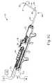
図1A~図1Dは、副鼻腔の小孔を拡張するために、副鼻腔の排液に関連するいくつかの他の通路を拡張するために、耳管を拡張するために、又はいくつかの他の解剖学的通路(例えば、耳、鼻、又は喉などの中)を拡張するために使用できる例示的な拡張器具アセンブリ(10)を示す。本実施例の拡張器具アセンブリ(10)は、ガイドワイヤ電源(12)、膨張供給源(14)、潅注液供給源(16)、及び拡張器具(20)を備える。いくつかの変形形態において、ガイドワイヤ電源(12)は光源を備える。いくつかの他の変形形態において、以下に記載されるように、ガイドワイヤ電源(12)は、IGSシステムの一部である。本実施例において、膨張供給源(14)は、生理食塩水の供給源を備える。しかしながら、任意の他の好適な流体(液体又は別の形態)の供給源が使用されてもよいことを理解されたい。また、本実施例において、潅注液供給源(16)は、生理食塩水の供給源を備える。しかしながら、繰り返すが、任意の他の好適な流体供給源が使用されてもよい。また、いくつかの変形形態において、洗浄液供給源(16)を省略してもよいことも理解されるべきである。I. Overview of Exemplary Dilatation Catheter Systems FIGS. 1A-1D dilate the eustachian tube to dilate the ostia of the sinuses and to dilate several other passageways associated with sinus drainage. 1 shows an exemplary dilator assembly (10) that can be used to dilate or dilate some other anatomical passageway (eg, in the ear, nose, or throat, etc.). Dilator assembly (10) of the present example comprises a guidewire power source (12), an inflation source (14), an irrigation fluid source (16), and a dilator (20). In some variations, the guidewire power supply (12) comprises a light source. In some other variations, the guidewire power source (12) is part of the IGS system, as described below. In this example, the inflation source (14) comprises a source of saline. However, it should be understood that any other suitable source of fluid (liquid or otherwise) may be used. Also in this example, the irrigation fluid supply (16) comprises a supply of saline. However, again, any other suitable fluid source may be used. It should also be appreciated that in some variations the cleaning fluid supply (16) may be omitted.
本実施例の拡張器具(20)は、ガイドワイヤ摺動部(24)、ガイドワイヤ回転部(26)、及び拡張カテーテル摺動部(28)を有するハンドル本体(22)を備える。ハンドル本体(22)は、人間の操作者によって片手で把持されるような大きさであり、そのように構成されている。摺動部(24、28)及び回転部(26)はまた、ハンドル本体(22)を握る同じ手で操作されるように位置付けられ、そのように構成されている。したがって、拡張器具(20)は、人間の操作者によって片手で完全に操作されることができることを理解されたい。 Dilation instrument (20) of the present example comprises a handle body (22) having a guidewire slider (24), a guidewire rotation (26), and a dilation catheter slider (28). The handle body (22) is sized and configured to be grasped in one hand by a human operator. Sliding portions (24, 28) and rotating portion (26) are also positioned and configured to be operated by the same hand that grips handle body (22). It should therefore be appreciated that the dilator (20) can be fully operated with one hand by a human operator.
A.例示的なガイドカテーテル
ガイドカテーテル(60)は、ハンドル本体(22)から遠位方向に延在する。ガイドカテーテル(60)は、開口遠位端(62)と、開口遠位端(62)の近位に形成された屈曲部(64)とを含む。本実施例において、拡張器具(20)は、いくつかの異なる種類のガイドカテーテル(60)を取り外し可能に受容するように構成され、各ガイドカテーテル(60)は、屈曲部(64)により形成された異なる角度を有する。これらの異なる角度は、異なる解剖学的構造へのアクセスを容易にすることができる。角度及び関連する解剖学的構造の様々な例は、本明細書に引用される1つ又は2つ以上の参照文献に記載され、更なる例は、本明細書の教示を考慮することで当業者には明らかとなろう。本実施例のガイドカテーテル(60)は、拡張器具(20)の使用中にガイドカテーテル(60)が屈曲部(64)の一定した構成を維持するように、硬質な材料(例えば、硬質金属及び/又は硬質プラスチックなど)で形成される。いくつかの変形形態において、拡張器具(20)は、ガイドカテーテル(60)の直線近位部分の長手方向軸を中心にハンドル本体(22)に対して、ガイドカテーテル(60)が回転可能なように更に構成され、それにより、様々な解剖学的構造へのアクセスを更に促進する。A. Exemplary Guide Catheter A guide catheter (60) extends distally from handle body (22). Guide catheter (60) includes an open distal end (62) and a bend (64) formed proximally of open distal end (62). In the present example, dilator (20) is configured to removably receive several different types of guide catheters (60), each guide catheter (60) being formed by a bend (64). have different angles. These different angles can facilitate access to different anatomy. Various examples of angles and related anatomical structures are described in one or more of the references cited herein, and further examples will be appreciated in light of the teachings herein. be clear to the trader. Guide catheter (60) of the present example is constructed of a rigid material (e.g., rigid metal and metal) such that guide catheter (60) maintains a consistent configuration of bends (64) during use of dilator (20). / or hard plastic, etc.). In some variations, dilator (20) is configured such that guide catheter (60) is rotatable relative to handle body (22) about the longitudinal axis of the straight proximal portion of guide catheter (60). , thereby further facilitating access to various anatomical structures.
B.例示的なガイドワイヤ
拡張器具(30)は、ガイドカテーテル(60)内に同軸状に配置されたガイドワイヤ(30)を更に備える。ガイドワイヤ摺動部(24)は、ハンドル本体(22)に対するガイドワイヤ摺動部(24)の並進が、ハンドル本体(22)に対するガイドワイヤ(30)の対応する並進を提供するように、ガイドワイヤ(30)に固定される。特に、近位位置(図1A)から遠位位置(図1B)へのガイドワイヤ摺動部(24)の並進により、ガイドワイヤ(30)の近位位置(図1A)から遠位位置(図1B)への対応する並進が生じる。ガイドワイヤ(30)が遠位位置にある場合、ガイドワイヤ(30)の遠位部分は、ガイドカテーテル(60)の開口遠位端(62)から遠位方向に突出する。ガイドワイヤ回転部(26)は、ガイドワイヤ(30)の長手方向軸を中心にガイドワイヤ(30)を回転させるように動作可能である。ガイドワイヤ回転部(26)は、ガイドワイヤ回転部(26)がガイドワイヤ摺動部(24)と長手方向に並進するように、ガイドワイヤ摺動部(24)と連結される。B. Exemplary Guidewire Dilator (30) further comprises a guidewire (30) coaxially disposed within guide catheter (60). The guidewire slide (24) is guided such that translation of the guidewire slide (24) relative to the handle body (22) provides corresponding translation of the guidewire (30) relative to the handle body (22). It is fixed to the wire (30). In particular, translation of guidewire slider (24) from a proximal position (Fig. IA) to a distal position (Fig. IB) causes guidewire (30) to move from a proximal position (Fig. IA) to a distal position (Fig. IA). A corresponding translation to 1B) occurs. When the guidewire (30) is in the distal position, the distal portion of the guidewire (30) projects distally from the open distal end (62) of the guide catheter (60). Guidewire rotator (26) is operable to rotate guidewire (30) about the longitudinal axis of guidewire (30). A guidewire rotatable portion (26) is coupled to the guidewire slidable portion (24) such that the guidewire rotatable portion (26) longitudinally translates with the guidewire slidable portion (24).
いくつかの変形形態において、ガイドワイヤ(30)は、ガイドワイヤ(30)の遠位端(32)の直近位に形成された事前形成された湾曲部を含む。いくつかの変形形態において、事前形成された屈曲部及びガイドワイヤ回転部(26)を介してもたらされる回転可能性が、拡張される副鼻腔、耳管、又は他の通路への遠位端(32)の位置調整及び挿入を容易にすることができる。また、いくつかの変形形態において、ガイドワイヤ(30)は、レンズに向かい延在する少なくとも1つの光ファイバ、又は他の透光性の機構も遠位端(32)に含む。この光ファイバは、光をガイドワイヤ電源(12)から遠位端(32)へと伝達できるように、ガイドワイヤ電源(12)と光学的に通信していてもよい。このような変形形態において、遠位端(32)が標的の解剖学的構造に到達したことを操作者に示すための視覚的フィードバックを提供するために、ガイドワイヤ(30)は、患者の皮膚を通る透過照明を提供することができる。 In some variations, guidewire (30) includes a pre-formed bend formed proximally of distal end (32) of guidewire (30). In some variations, the rotatability provided via the pre-formed bend and guidewire rotator (26) steers the distal end into the expanded sinus, ear canal, or other passageway ( 32) can be easily aligned and inserted. In some variations, guidewire (30) also includes at least one optical fiber or other translucent feature at distal end (32) that extends toward the lens. The optical fiber may be in optical communication with the guidewire power source (12) such that light may be transmitted from the guidewire power source (12) to the distal end (32). In such variations, the guidewire (30) is attached to the patient's skin to provide visual feedback to the operator to indicate that the distal end (32) has reached the target anatomy. can provide transmitted illumination through the
単に一例として、ガイドワイヤ(30)は、米国特許第9,155,492号(開示内容は参照により本明細書に組み込まれている)の教示の少なくとも一部に従って構成されることができる。いくつかの変形形態では、ガイドワイヤ(30)は、Acclarent,Inc.(Irvine,California)によるRelieva Luma Sentry(商標)Sinus Illumination Systemに類似して構成されている。加えて又はその代替えとして、1本又は2本以上の光ファイバを含むガイドワイヤ(30)は、より詳細に後述するように、ガイドワイヤ(30)にIGSシステムとの適合性をもたらすことを可能にする、センサ及び少なくとも1本のワイヤを含んでもよい。ガイドワイヤ(30)に組み込んでもよい他の機構及び操作性能が、本明細書の教示を考慮することで当業者には明らかとなろう。 Solely by way of example, guidewire (30) may be constructed in accordance with at least a portion of the teachings of US Pat. No. 9,155,492, the disclosure of which is incorporated herein by reference. In some variations, guidewire (30) is manufactured by Acclarent, Inc.; (Irvine, Calif.) similar to the Relieva Luma Sentry™ Sinus Illumination System. Additionally or alternatively, a guidewire (30) comprising one or more optical fibers can make the guidewire (30) compatible with an IGS system, as described in more detail below. may include a sensor and at least one wire for enabling the Other features and operational capabilities that may be incorporated into guidewire (30) will be apparent to those skilled in the art in view of the teachings herein.
C.例示的な拡張カテーテル
拡張器具(30)は、ガイドカテーテル(60)内に同軸状に配置された拡張カテーテル(40)を更に備える。拡張カテーテル摺動部(28)は、ハンドル本体(22)に対する拡張カテーテル摺動部(28)の並進が、ハンドル本体(22)に対する拡張カテーテル(40)の対応する並進を提供するように、拡張カテーテル(40)に固定される。特に、近位位置(図1B)から遠位位置(図1C)への拡張カテーテル摺動部(28)の並進により、拡張カテーテル(40)の近位位置(図1B)から遠位位置(図1C)への対応する並進を生じる。拡張カテーテル(40)が遠位位置にある場合、拡張カテーテル(40)の遠位部分は、ガイドカテーテル(60)の開口遠位端(62)から遠位方向に突出する。図1Cでも分かるように、ガイドワイヤ(30)及び拡張カテーテルが共に遠位位置にある場合、ガイドワイヤ(30)の遠位部分は、拡張カテーテル(40)の開口遠位端から遠位方向に突出する。C. Exemplary Dilation Catheter The dilation device (30) further comprises a dilation catheter (40) coaxially disposed within the guide catheter (60). Dilation catheter slide (28) is expanded such that translation of dilation catheter slide (28) relative to handle body (22) provides corresponding translation of dilation catheter (40) relative to handle body (22). It is secured to the catheter (40). In particular, translation of dilatation catheter slide (28) from a proximal position (Fig. IB) to a distal position (Fig. 1C) causes dilatation catheter (40) to move from a proximal position (Fig. IB) to a distal position (Fig. 1C) yields a corresponding translation. When dilatation catheter (40) is in the distal position, a distal portion of dilatation catheter (40) projects distally from open distal end (62) of guide catheter (60). As can also be seen in FIG. 1C, when guidewire (30) and dilation catheter are both in a distal position, the distal portion of guidewire (30) extends distally from the open distal end of dilation catheter (40). protrude.
本実施例の拡張カテーテル(40)は、拡張カテーテル(40)の開口遠位端(42)の直近位に位置する非伸縮性バルーン(44)を備える。バルーン(44)は、膨張供給源(14)と流体連通している。膨張供給源(14)は、流体(例えば、生理食塩水など)をバルーン(44)へ出し入れし、それによりバルーン(44)が非膨張状態と膨張状態との間で移行するように構成されている。図1Cは、非膨張状態のバルーン(44)を示す。図1Dは、膨張状態のバルーン(44)を示す。いくつかの変形形態において、膨張供給源(14)は、手動で作動される加圧流体の供給源を備える。いくつかのこのような変形形態において、手動で作動される加圧流体の供給源は、米国特許出願公開第2014/0074141号、発明の名称「Inflator for Dilation of Anatomical Passageway」(2014年3月13日公開)(開示内容は参照により本明細書に組み込まれている)の教示の少なくとも一部に従って構成され、動作可能である。加圧流体の供給源を提供するために使用することができる他の好適な構成は、本明細書の教示を考慮することで当業者には明らかとなろう。 Dilation catheter (40) of the present example comprises a non-stretchable balloon (44) located just proximal to the open distal end (42) of dilatation catheter (40). A balloon (44) is in fluid communication with an inflation source (14). Inflation source (14) is configured to move a fluid (eg, saline, etc.) into and out of balloon (44), thereby transitioning balloon (44) between an uninflated state and an inflated state. there is Figure 1C shows the balloon (44) in an uninflated state. FIG. 1D shows the balloon (44) in an inflated state. In some variations, the inflation source (14) comprises a manually actuated source of pressurized fluid. In some such variations, the manually actuated source of pressurized fluid is disclosed in U.S. Patent Application Publication No. 2014/0074141, entitled "Inflator for Dilation of Anatomical Pathway" (March 13, 2014). Published 1997/03/07, the disclosure of which is incorporated herein by reference. Other suitable configurations that can be used to provide a source of pressurized fluid will be apparent to those skilled in the art in view of the teachings herein.
図示されないが、拡張カテーテル(40)が、互いに対して流体隔離している少なくとも2つの別々の管腔を含む場合があることを理解されたい。一方の管腔は、バルーン(44)と膨張供給源(14)との間の流体連通のための経路を提供してもよい。もう一方の管腔は、ガイドワイヤ(30)を摺動可能に受容するための経路を提供してもよい。 Although not shown, it should be understood that dilatation catheter (40) may include at least two separate lumens that are fluidly isolated from each other. One lumen may provide a pathway for fluid communication between balloon (44) and inflation source (14). The other lumen may provide a pathway for slidably receiving a guidewire (30).
本実施例の拡張カテーテル(40)は、バルーン(44)を出入りする流体の連通に基づき非拡張状態と拡張状態との間で移行するように構成されているが、拡張カテーテル(40)は拡張器として機能する様々な他の種類の構造を含む場合があることを理解されたい。単に一例として、バルーン(44)は、いくつかの他の変形形態において、機械的な拡張器と置き換えられることができる。拡張カテーテル(40)は、本明細書に引用される様々な参照文献のうちの任意のものに従って構成され、動作可能であってもよい。いくつかの変形形態において、拡張器カテーテル(40)は、Acclarent,Inc.(Irvine,California)によるRelieva Ultirra(商標)Sinus Balloon Catheterに類似して構成され、動作可能である。いくつかの他の変形形態において、拡張器カテーテル(40)は、Acclarent,Inc.(Irvine,California)によるRelieva Solo Pro(商標)Sinus Balloon Catheterに類似して構成され、動作可能である。拡張カテーテル(40)の他の好適な変更例は、本明細書の教示を考慮することで当業者には明らかとなろう。 Although dilatation catheter (40) of the present example is configured to transition between an unexpanded state and an expanded state based on fluid communication to and from balloon (44), dilatation catheter (40) It should be understood that various other types of structures that function as vessels may be included. Merely by way of example, balloon (44) may be replaced with a mechanical dilator in some other variations. Dilatation catheter (40) may be constructed and operable in accordance with any of the various references cited herein. In some variations, dilator catheter (40) is manufactured by Acclarent, Inc.; (Irvine, Calif.) constructed and operable similar to the Relieva Ultirra™ Sinus Balloon Catheter. In some other variations, the dilator catheter (40) is manufactured by Acclarent, Inc.; (Irvine, Calif.) configured and operable similar to the Relieva Solo Pro™ Sinus Balloon Catheter. Other suitable variations of dilatation catheter (40) will be apparent to those skilled in the art in view of the teachings herein.
D.例示的な潅注機構
場合によっては、解剖学的部位に潅注を行うことが望ましい場合がある。例えば、拡張カテーテル(40)を使用して、口、又は副鼻腔に関連する他の排液通路を拡張した後に、副鼻腔及び鼻腔に潅注を行うことが望ましい場合がある。このような潅注を行って、拡張処置の後に存在する場合がある血液などを流し出してもよい。このような一部の症例において、ガイドワイヤ(30)及び拡張カテーテル(40)は取り外される一方で、ガイドカテーテル(60)を患者体内に残すことができる場合がある。次に、専用の潅注カテーテル(図示せず)は、ガイドカテーテル(60)に挿入され、チューブ(50)を介して潅注液供給源(16)と連結されて、患者の解剖学的部位の潅注を可能にすることができる。拡張カテーテル(60)の除去後に潅注部位に到達するようにガイドカテーテル(60)を通して供給され得る潅注カテーテルの一例は、Acclarent,Inc.(Irvine,California)によるRelieva Vortex(登録商標)Sinus Irrigation Catheterである。拡張カテーテル(40)の除去後に潅注部位に到達するようにガイドカテーテル(60)を通して供給され得る潅注カテーテルの別の例は、Acclarent,Inc.(Irvine,California)によるRelieva Ultirra(登録商標)Sinus Irrigation Catheterである。D. Exemplary Irrigation Mechanisms In some cases, it may be desirable to irrigate an anatomical site. For example, it may be desirable to irrigate the sinuses and nasal cavities after dilating the mouth or other drainage passageways associated with the sinuses using a dilatation catheter (40). Such irrigation may be performed to flush out blood or the like that may be present after the dilation procedure. In some such cases, the guidewire (30) and dilation catheter (40) may be removed while the guide catheter (60) remains within the patient. A dedicated irrigation catheter (not shown) is then inserted into the guide catheter (60) and connected to the irrigation fluid supply (16) via tubing (50) to irrigate the patient's anatomy. can make it possible. An example of an irrigation catheter that can be fed through guide catheter (60) to reach the irrigation site after removal of dilatation catheter (60) is provided by Acclarent, Inc.; (Irvine, Calif.) Relieva Vortex® Sinus Irrigation Catheter. Another example of an irrigation catheter that may be fed through guide catheter (60) to reach the irrigation site after removal of dilatation catheter (40) is provided by Acclarent, Inc.; (Irvine, Calif.) Relieva Ultirra® Sinus Irrigation Catheter.
いくつかの他の変形形態において、拡張カテーテル(40)は、拡張カテーテル(40)がチューブ(50)を介して潅注液供給源(16)と連結可能なように、遠位端(42)近辺に更なる潅注管腔及び関連する一連の潅注ポートを含む。したがって、潅注を行うために必要とされる、別の専用の潅注カテーテルを必要としない。 In some other variations, dilatation catheter (40) is positioned near distal end (42) such that dilatation catheter (40) is connectable to irrigation fluid supply (16) via tube (50). contains additional irrigation lumens and associated series of irrigation ports. Therefore, no separate dedicated irrigation catheter is required to perform the irrigation.
あくまで一例として、潅注は、米国特許出願公開第2008/0183128号、発明の名称「Methods, Devices and Systems for Treatment and/or Diagnosis of Disorders of the Ear,Nose and Throat」(2008年7月31日公開)(開示内容は参照により本明細書に組み込まれている)の教示の少なくとも一部に従って行うことができる。当然ながら、潅注は拡張処置なしで行うことができ、拡張処置もまた、潅注なしで完了させることができる。したがって、拡張流体供給源(16)及びチューブ(50)は単に任意選択的であることを理解されたい。 By way of example only, irrigation is described in U.S. Patent Application Publication No. 2008/0183128, entitled "Methods, Devices and Systems for Treatment and/or Diagnosis of Disorders of the Ear, Nose and Throat," published July 31, 2008. ), the disclosure of which is incorporated herein by reference, at least in part. Of course, irrigation can be performed without dilation, and dilation can also be completed without irrigation. Therefore, it should be understood that expansion fluid supply (16) and tube (50) are merely optional.
E.例示的な変更例
本実施例において、ガイドワイヤ(30)は、ガイドカテーテル(60)内に同軸状に配置された拡張カテーテル(40)内に同軸状に配置されている。いくつかの他の変形形態において、ガイドカテーテル(60)は、拡張器具(20)から省略される。いくつかのこのような変形形態において、ガイドワイヤ(30)及び拡張カテーテル(40)を誘導するために、柔軟なガイド部材が使用される。いくつかのこのような変形形態において、ガイドワイヤ(30)は省略され、拡張カテーテル(40)は、内部の柔軟なガイド部材の外側周辺に摺動可能に配置される。いくつかの他の変形形態において、ガイドワイヤ(30)は、内部の柔軟なガイド部材の外側周辺に摺動可能に配置され、拡張カテーテル(40)は、ガイドワイヤ(30)の外側周辺に摺動可能に配置される。更に他の変形形態において、ガイドワイヤ(30)は、内部の柔軟なガイド部材内に摺動可能に配置され、拡張カテーテル(40)は、柔軟なガイド部材の外側周辺に摺動可能に配置される。E. Exemplary Variation In the present example, guidewire (30) is coaxially disposed within dilatation catheter (40), which is coaxially disposed within guide catheter (60). In some other variations, guide catheter (60) is omitted from dilator (20). In some such variations, a flexible guide member is used to guide the guidewire (30) and dilation catheter (40). In some such variations, the guidewire (30) is omitted and the dilation catheter (40) is slidably positioned around the outside of the inner flexible guide member. In some other variations, the guidewire (30) is slidably positioned around the outside of the inner flexible guide member and the dilatation catheter (40) slides around the outside of the guidewire (30). placed movably. In yet another variation, the guidewire (30) is slidably disposed within the inner flexible guide member and the dilatation catheter (40) is slidably disposed around the outer periphery of the flexible guide member. be.
単に一例として、柔軟なガイド部材を含む拡張器具(20)の変形形態は、米国特許出願公開第2016/0310714号、発明の名称「Balloon Dilation System with Malleable Internal Guide」(2016年10月27日公開)(開示内容は参照により本明細書に組み込まれている)の教示の少なくとも一部に従って構成され、動作可能であってもよい。別の単なる説明例として、柔軟なガイド部材を含む拡張器具(20)の変形形態は、米国特許出願公開第2017/0120020号、発明の名称「Apparatus for Bending Malleable Guide of Surgical Instrument」(2017年5月4日公開)(開示内容は参照により本明細書に組み込まれている)、及び/又は米国特許出願公開第2012/0071857号、発明の名称「Methods and Apparatus for Treating Disorders of the Sinuses」(2012年3月22日公開)(開示内容は参照により本明細書に組み込まれている)の教示の少なくとも一部に従って構成され、動作可能であってもよい。 Solely by way of example, a variation of a dilator (20) that includes a flexible guide member is disclosed in U.S. Patent Application Publication No. 2016/0310714, entitled "Balloon Dilation System with Malleable Internal Guide," published Oct. 27, 2016. ), the disclosure of which is incorporated herein by reference, at least in part. As another illustrative example only, a variation of an expander (20) that includes a flexible guide member is described in U.S. Patent Application Publication No. 2017/0120020, entitled "Apparatus for Bending Malleable Guide of Surgical Instrument" (May 2017). published May 4) (the disclosure of which is incorporated herein by reference), and/or U.S. Patent Application Publication No. 2012/0071857, entitled "Methods and Apparatus for Treating Disorders of the Sinuses" (2012). may be constructed and operable in accordance with at least a portion of the teachings of US Pat.
IGSシステムの観点から以下に記載される拡張器具(20)の変更例は、硬質なガイドカテーテル(60)を有する拡張器具(20)の変形形態に組み込まれてもよいIGSシステムの観点から、以下に記載される拡張器具(20)の変更例と同様に柔軟なガイドを有する拡張器具(20)の変形形態に組み込まれてもよいことが理解されよう。 Modifications of the dilator (20) described below in terms of the IGS system may be incorporated into variations of the dilator (20) having a rigid guide catheter (60), in terms of the IGS system: It will be appreciated that variations of dilator (20) having flexible guides as well as variations of dilator (20) described in .
以下の様々な実施例は、患者体内の器具のナビゲーションを提供するIGSシステムの使用について記載する。特に、以下の様々な実施例は、IGSシステム機構を組み込むように拡張器具アセンブリ(10)を変更することができる方法について記載する。しかしながら、拡張器具アセンブリ(10)は、IGSシステム構成要素と共に使用されることに加えて、従来の画像誘導器具と共に使用されてもよいこともまた理解されるべきである。例えば、拡張器具アセンブリ(10)は、内視鏡と共に使用され、患者体内のガイドカテーテル(60)の最初の位置決めを少なくとも提供することができる。単に一例として、このような内視鏡は、米国特許出願公開第2010/0030031号(開示内容は参照により本明細書に組み込まれている)の教示の少なくともいくつかに従って構成されてもよい。本明細書に記載の拡張器具アセンブリ(10)の様々な変形形態と共に使用されてもよい内視鏡の他の好適な種類は、当業者には明らかであろう。 Various examples below describe the use of an IGS system to provide navigation of instruments within a patient. In particular, various examples below describe how the expander assembly (10) can be modified to incorporate IGS system features. However, it should also be understood that the dilator assembly (10) may be used with conventional image-guided instruments in addition to being used with IGS system components. For example, dilator assembly (10) can be used with an endoscope to at least provide initial positioning of guide catheter (60) within a patient. Solely by way of example, such an endoscope may be constructed in accordance with at least some of the teachings of US Patent Application Publication No. 2010/0030031, the disclosure of which is incorporated herein by reference. Other suitable types of endoscopes that may be used with the various variations of dilator assembly (10) described herein will be apparent to those skilled in the art.
II.例示的な画像誘導手術ナビゲーションシステム
図2は、IGSを使用してENT処置を行い得る、例示的なIGSナビゲーションシステム(100)を示す。場合によっては、IGSナビゲーションシステム(100)は、副鼻腔口を拡張するため、又はいくつかの他の解剖学的通路(例えば、耳、鼻、又は喉などの中)を拡張するために、拡張器具アセンブリ(10)を使用することができる処置中に使用される。しかし、IGSナビゲーションシステム(100)を、種々の他の種類の処置で容易に使用可能であることを理解すべきである。II. Exemplary Image-Guided Surgical Navigation System FIG. 2 shows an exemplary IGS navigation system (100) that can perform ENT procedures using an IGS. In some cases, the IGS navigation system (100) expands to dilate the sinus ostia, or to dilate some other anatomical passageway (eg, in the ear, nose, or throat, etc.). Used during procedures in which the instrument assembly (10) can be used. However, it should be appreciated that the IGS navigation system (100) can readily be used in a variety of other types of procedures.
本明細書に記載の構成要素及び操作性を有することに加えて又はそれに代えて、IGSナビゲーションシステム(100)は、以下の文献の教示の少なくとも一部に従って構成され動作可能であってもよい。すなわち、米国特許第8,702,626号、発明の名称「Guidewires for Performing Image Guided Procedures」(2014年4月22日発行)(開示内容は参照により本明細書に組み込まれている)、同第8,320,711号、発明の名称「Anatomical Modeling from a 3-D Image and a Surface Mapping」(2012年11月27日発行)(開示内容は参照により本明細書に組み込まれている)、同第8,190,389号、発明の名称「Adapter for Attaching Electromagnetic Image Guidance Components to a Medical Device」(2012年5月29日発行)(開示内容は参照により本明細書に組み込まれている)、同第8,123,722号、発明の名称「Devices,Systems and Methods for Treating Disorders of the Ear,Nose and Throat」(2012年2月28日発行)(開示内容は参照により本明細書に組み込まれている)、及び同第7,720,521号、発明の名称「Methods and Devices for Performing Procedures within the Ear,Nose,Throat and Paranasal Sinuses」(2010年5月18日発行)(開示内容は本明細書において参照により組み込まれている)。 In addition to or in lieu of having the components and operability described herein, the IGS navigation system (100) may be constructed and operable in accordance with at least some of the teachings of the following documents: US Pat. No. 8,702,626, entitled "Guidewires for Performing Image Guided Procedures," issued Apr. 22, 2014 (the disclosure of which is incorporated herein by reference), ibid. 8,320,711, entitled "Anatomical Modeling from a 3-D Image and a Surface Mapping," published Nov. 27, 2012 (the disclosure of which is incorporated herein by reference), ibid. 8,190,389, entitled "Adapter for Attaching Electromagnetic Image Guidance Components to a Medical Device," published May 29, 2012 (the disclosure of which is incorporated herein by reference), ibid. No. 8,123,722, entitled "Devices, Systems and Methods for Treating Disorders of the Ear, Nose and Throat", published Feb. 28, 2012, the disclosure of which is incorporated herein by reference; No. 7,720,521, entitled "Methods and Devices for Performing Procedures within the Ear, Nose, Throat and Paranasal Siuses", published May 18, 2010 (disclosed herein). incorporated by reference in).
同様に、本明細書に記載の構成要素及び操作性を有することに加えて又はそれに代えて、IGSナビゲーションシステム(100)は、以下の文献の教示の少なくとも一部に従って構成され動作可能であってもよい。すなわち、米国特許出願公開第2014/0364725号、発明の名称「Systems and Methods for Performing Image Guided Procedures within the Ear,Nose,Throat and Paranasal Sinuses」(2014年12月11日公開)(開示内容は参照により本明細書に組み込まれている)、同第2014/0200444号、発明の名称「Guidewires for Performing Image Guided Procedures」(2014年7月17日公開)(開示内容は参照により本明細書に組み込まれている)、米国特許第9,198,736号、発明の名称「Adapter for Attaching Electromagnetic Image Guidance Components to a Medical Device」(2015年12月1日発行)(開示内容は参照により本明細書に組み込まれている)、米国特許出願公開第2011/0060214号、発明の名称「Systems and Methods for Performing Image Guided Procedures within the Ear,Nose,Throat and Paranasal Sinuses」(2011年3月10日公開)(開示内容は参照により本明細書に組み込まれている)、米国特許第9,167,961号、発明の名称「Methods and Apparatus for Treating Disorders of the Ear Nose and Throat」(2015年10月27日発行)(開示内容は参照により本明細書に組み込まれている)、及び米国特許出願公開第2007/0208252号、発明の名称「Systems and Methods for Performing Image Guided Procedures within the Ear,Nose,Throat and Paranasal Sinuses」(2007年9月6日公開)(開示内容は参照により本明細書に組み込まれている)。 Similarly, in addition to or in lieu of having the components and operability described herein, the IGS navigation system (100) is constructed and operable in accordance with at least some of the teachings of the following references: good too. No. 2014/0364725, entitled "Systems and Methods for Performing Image Guided Procedures within the Ear, Nose, Throat and Paranasal Siuses," published Dec. 11, 2014 (disclosure incorporated by reference). No. 2014/0200444, entitled "Guidewires for Performing Image Guided Procedures," published Jul. 17, 2014, the disclosure of which is incorporated herein by reference. U.S. Pat. No. 9,198,736, entitled "Adapter for Attaching Electromagnetic Image Guidance Components to a Medical Device," issued Dec. 1, 2015, the disclosure of which is incorporated herein by reference. U.S. Patent Application Publication No. 2011/0060214, entitled "Systems and Methods for Performing Image Guided Procedures within the Ear, Nose, Throat and Paranasal Siuses" (published March 10, 2011) (disclosure is incorporated herein by reference), U.S. Pat. No. 9,167,961, entitled "Methods and Apparatus for Treating Disorders of the Ear Nose and Throat," issued Oct. 27, 2015 (disclosure the contents of which are incorporated herein by reference), and U.S. Patent Application Publication No. 2007/0208252, entitled "Systems and Methods for Performing Image Guided Procedures within the Ear, Nose, Throat and Paranasal Siuses" (2007 Published Sept. 6, 2009) (the disclosure of which is incorporated herein by reference).
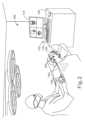
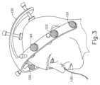
本実施例のIGSナビゲーションシステム(100)は、一式の磁場発生器(122)を含んでいる。外科処置が始まる前に、磁場発生器(122)を患者の頭部に固定する。図3で最も良く分かるように、磁場発生器(122)は、フレーム(120)に組み込まれており、フレーム(120)は、患者の頭部にクランプ止めされている。磁場発生器(122)は、この例では患者の頭部に固定されているが、磁場発生器(122)は、これに代えて種々の他の適切な位置に、種々の他の適切な構造で配置されていてもよいことを理解すべきである。単に一例として、磁場発生器(122)は、患者が位置付けられたテーブル又は椅子に固定された独立した構造上に、患者の頭部に対して適所にロックされた床取り付け式スタンド上に、並びに/又は任意の他の好適な位置及び/若しくは任意の他の好適な構造上に設置することができる。 The IGS navigation system (100) of the present example includes a set of magnetic field generators (122). The magnetic field generator (122) is secured to the patient's head before the surgical procedure begins. As best seen in FIG. 3, the magnetic field generator (122) is incorporated into a frame (120), which is clamped to the patient's head. Although magnetic field generator (122) is fixed to the patient's head in this example, magnetic field generator (122) may alternatively be in various other suitable locations and various other suitable structures. It should be understood that it may be placed in By way of example only, the magnetic field generator (122) may be on a separate structure fixed to the table or chair on which the patient is positioned, on a floor-mounted stand locked in place against the patient's head, and /or may be installed in any other suitable location and/or on any other suitable structure.
磁場発生器(122)は、患者の頭部の周囲に電磁場を発生させるように動作可能である。詳細には、磁場発生器(122)は、フレーム(120)に近接する領域内に異なる周波数の交流磁場を伝達するように動作する。それにより、磁場発生器(122)は、患者の副鼻腔及び患者の頭部内の他の位置に挿入されるナビゲーションガイドワイヤ(130)の位置を追跡することができる。磁場発生器(122)を形成し、駆動するために使用することができる種々の適した構成要素は、本明細書の教示を考慮することで当業者には明らかとなろう。 A magnetic field generator (122) is operable to generate an electromagnetic field around the patient's head. Specifically, the magnetic field generators (122) operate to transmit alternating magnetic fields of different frequencies into a region proximate to the frame (120). The magnetic field generator (122) can thereby track the position of a navigational guidewire (130) inserted into the patient's sinuses and other locations within the patient's head. Various suitable components that can be used to form and drive the magnetic field generator (122) will be apparent to those skilled in the art in view of the teachings herein.
ナビゲーションガイドワイヤ(130)は、上述のガイドワイヤ(30)の代替物として使用することができ、磁場発生器(122)によって発生された磁場内の運動に応答するセンサ(図示せず)を含んでもよい。特に、ナビゲーションガイドワイヤ(130)のセンサにより発生された信号は、プロセッサ(110)により処理され、患者内のナビゲーションガイドワイヤ(130)の3次元位置を決定することができる。センサが取り得る様々な好適な形状は、本明細書の教示を考慮することにより、特に、IGSナビゲーションシステム(100)の観点から本明細書に引用される数々の参照文献を考慮することにより、当業者に明らかになるであろう。拡張器具アセンブリ(10)のガイドワイヤ(30)の代替物として使用される場合、ナビゲーションガイドワイヤ(130)は、副鼻腔の小孔を拡張するため又はいくつかの他の解剖学的通路(例えば、耳、鼻、又は喉などの中)を拡張するための処置の実行中に、患者内の拡張器具アセンブリ(10)の器具のナビゲーションを容易にし得ることが理解されるべきである。また、拡張器具アセンブリ(10)の他の構成要素は、以下に記載の例示的な別の拡張カテーテル(200)を非限定的に含むナビゲーションガイドワイヤ(130)のセンサなどのセンサを組み込んでもよいことが、理解されるべきである。 The navigation guidewire (130) can be used as an alternative to the guidewire (30) described above and includes sensors (not shown) responsive to movement within the magnetic field generated by the magnetic field generator (122). It's okay. In particular, signals generated by the sensors of navigation guidewire (130) can be processed by processor (110) to determine the three-dimensional position of navigation guidewire (130) within the patient. The various suitable shapes that the sensor can take are determined in light of the teachings herein, particularly in light of the numerous references cited herein in terms of the IGS navigation system (100). will be apparent to those skilled in the art. When used as a replacement for guidewire (30) in dilator assembly (10), navigation guidewire (130) may be used to dilate a sinus ostium or some other anatomical passageway (e.g., , ear, nose, or throat) may facilitate instrument navigation of the dilator assembly (10) within the patient. Other components of the dilator assembly (10) may also incorporate sensors such as those of the navigational guidewire (130), including but not limited to the exemplary alternate dilation catheter (200) described below. should be understood.
本実施例のIGSナビゲーションシステム(100)は、プロセッサ(110)を更に含んでおり、プロセッサ(110)は、磁場発生器(122)及びIGSナビゲーションシステム(100)の他の要素を制御する。プロセッサ(110)は、1つ又は2つ以上のメモリと通信する処理ユニットを含んでいる。本実施例のプロセッサ(110)は、キーパッド及び/又はマウス若しくはトラックボールなどのポインティングデバイスを含む操作制御部(112)を備える含むコンソール(116)内に実装されている。医師は、外科処置を行っている間、プロセッサ(110)と相互作用する操作制御部(112)を使用する。 IGS navigation system (100) of the present example further includes a processor (110), which controls magnetic field generator (122) and other elements of IGS navigation system (100). Processor (110) includes a processing unit in communication with one or more memories. The processor (110) of the present example is implemented within a console (116) that includes operating controls (112) that include a keypad and/or pointing device such as a mouse or trackball. A physician uses operational controls (112) that interact with processor (110) while performing a surgical procedure.
コンソール(116)も、システム(100)の他の要素に接続する。例えば、図2に示されるように、連結ユニット(132)は、ナビゲーションガイドワイヤ(130)の近位端に固定される。本実施例の連結ユニット(132)は、コンソール(116)とナビゲーションガイドワイヤ(130)との間のデータ及び他の信号の無線通信を与えるように構成される。いくつかの変形形態では、連結ユニット(132)は、コンソール(116)からのデータ及び他の信号を通信することもなく、ナビゲーションガイドワイヤ(130)からコンソール(116)へとデータ及び他の信号を一方向に単に通信する。いくつかの他の変形形態では、連結ユニット(132)は、ナビゲーションガイドワイヤ(130)とコンソール(116)との間のデータ又は他の信号の双方向通信を与える。本実施例の連結ユニット(132)はコンソール(116)と無線で連結しているが、いくつかの他の変形形態は、連結ユニット(132)とコンソール(116)との間を有線連結してもよい。連結ユニット(132)に組み込むことが可能な種々の他の適した機構及び機能性は、本明細書の教示を考慮することで当業者には明らかとなろう。 A console (116) also connects to other elements of the system (100). For example, as shown in FIG. 2, coupling unit (132) is secured to the proximal end of navigation guidewire (130). Coupling unit (132) of the present example is configured to provide wireless communication of data and other signals between console (116) and navigation guidewire (130). In some variations, coupling unit (132) communicates data and other signals from navigation guidewire (130) to console (116) without communicating data and other signals from console (116). simply communicate in one direction. In some other variations, coupling unit (132) provides bidirectional communication of data or other signals between navigation guidewire (130) and console (116). Although coupling unit (132) of the present example couples wirelessly with console (116), some other variations include a wired coupling between coupling unit (132) and console (116). good too. Various other suitable features and functionality that may be incorporated into coupling unit (132) will be apparent to those skilled in the art in view of the teachings herein.
プロセッサ(110)は、プロセッサ(110)のメモリに格納されたソフトウェアを使用し、システム(100)を較正し、操作する。かかる操作は、磁場発生器(122)を駆動すること、ナビゲーションガイドワイヤ(130)からのデータを処理すること、操作制御部(112)からのデータを処理すること、及びディスプレイスクリーン(114)を駆動することを含む。ソフトウェアは、例えば、電子形態で、ネットワークによってプロセッサ(110)にダウンロードされてもよく、あるいはこれに代えて、又はこれに加えて、磁気メモリ、光学メモリ、若しくは電子メモリなどの非一時的な有形媒体上に提供され、及び/若しくは格納されてもよい。 The processor (110) uses software stored in the memory of the processor (110) to calibrate and operate the system (100). Such operations include driving the magnetic field generator (122), processing data from the navigation guidewire (130), processing data from the operational controls (112), and controlling the display screen (114). Including driving. The software may be downloaded to the processor (110) over a network, for example in electronic form, or may alternatively or additionally be stored in a non-transitory tangible form such as magnetic, optical or electronic memory. It may be provided and/or stored on media.
プロセッサ(110)は更に、ディスプレイスクリーン(114)を介してビデオをリアルタイムで提供するように動作可能であり、ナビゲーションガイドワイヤ(130)の遠位端の位置を、患者の頭部のビデオカメラ画像、患者の頭部のCTスキャン画像、並びに/又は患者の鼻腔内の及び患者の鼻腔に隣接する生体構造のコンピュータで生成された3次元モデルとの関連で示す。ディスプレイスクリーン(114)は、このような画像を同時に、及び/又は互いに重ね合わせて表示してもよい。更に、ディスプレイスクリーン(114)は、外科処置中にこのような画像を表示してもよい。このような表示された画像は、患者の頭部に挿入される器具(例えば、ナビゲーションガイドワイヤ(130))のグラフィック表示も含んでいてもよく、その結果、操作者は、その実際の位置で、リアルタイムで器具のバーチャルレンダリングを見ることができる。このようなグラフィック表示は、実際に器具のように見えることができるか、又はドット、クロスヘアなどのより単純な表示であってもよい。単に一例として、ディスプレイ画面(114)は、米国特許出願公開第2016/0008083号、発明の名称「Guidewire Navigation for Sinuplasty」(2016年1月14日公開)(開示内容は参照により本明細書に組み込まれている)の教示の少なくとも一部に従って画像を提供してもよい。操作者が内視鏡も使用している場合には、内視鏡画像をディスプレイスクリーン(114)に提供することもできる。ディスプレイスクリーン(114)によって与えられる画像は、患者の頭部内で器具を動かし、他の方法で操作する際に操作者を誘導するのに役立ち得る。 Processor (110) is further operable to provide real-time video via display screen (114) to indicate the position of the distal end of navigation guidewire (130) from a video camera image of the patient's head. , a CT scan image of the patient's head, and/or a computer-generated three-dimensional model of the anatomy within and adjacent to the patient's nasal cavity. A display screen (114) may display such images simultaneously and/or overlaid on each other. Further, display screen (114) may display such images during a surgical procedure. Such displayed images may also include a graphical representation of an instrument (e.g., navigational guidewire (130)) inserted into the patient's head, so that the operator can see in its actual position. , you can see a virtual rendering of the instrument in real time. Such graphical representations can actually look like appliances, or may be simpler representations such as dots, crosshairs, and the like. Merely by way of example, the display screen (114) is described in U.S. Patent Application Publication No. 2016/0008083, entitled "Guidewire Navigation for Sinuplasty," published Jan. 14, 2016, the disclosure of which is incorporated herein by reference. The images may be provided in accordance with at least some of the teachings of An endoscopic image may also be provided on the display screen (114) if the operator is also using an endoscope. The images provided by the display screen (114) may help guide the operator in moving and otherwise manipulating the instrument within the patient's head.
本実施例では、ナビゲーションガイドワイヤ(130)は、ナビゲーションガイドワイヤ(130)の遠位端に1つ又は2つ以上のコイルを含む。このようなコイルは、上述のようなセンサとして機能する。このようなコイルが磁場発生器(122)によって発生された電磁場の中に位置付けられると、その磁場内でのコイルの運動によってコイルに電流が発生し、この電流はナビゲーションガイドワイヤ(130)内の導電路に沿って、更に連結ユニット(132)を介してプロセッサ(110)に伝送され得る。この現象によって、IGSナビゲーションシステム(00)は、以下に更に詳細に記載されるように、3次元空間内でナビゲーションガイドワイヤ(130)の遠位端の位置を決定することを可能にし得る。詳細には、プロセッサ(110)は、ナビゲーションガイドワイヤ(130)の遠位端の位置座標を、ナビゲーションガイドワイヤ(130)内のコイルの位置関連信号から計算するアルゴリズムを実行する。 In the present example, navigation guidewire (130) includes one or more coils at the distal end of navigation guidewire (130). Such coils function as sensors as described above. When such a coil is positioned within the electromagnetic field generated by the magnetic field generator (122), the coil's motion within that field generates a current in the coil which is directed into the navigation guidewire (130). Along the conductive path, it can be further transmitted to the processor (110) via the coupling unit (132). This phenomenon may allow the IGS navigation system (00) to determine the position of the distal end of the navigation guidewire (130) in three-dimensional space, as described in more detail below. Specifically, the processor (110) executes an algorithm that calculates the position coordinates of the distal end of the navigation guidewire (130) from the position-related signals of the coils within the navigation guidewire (130).
場合によっては、ナビゲーションガイドワイヤ(130)を使用して、患者の鼻腔内の及び患者の鼻腔に隣接する生体構造の3次元モデルを生成することを、患者の鼻腔内の拡張カテーテルシステム(100)に対するナビゲーションをもたらすために用いることに加えて行う。あるいは、任意の他の好適なデバイスを使用して、患者の鼻腔内の及び患者の鼻腔に隣接する生体構造の3次元モデルを生成することを、ナビゲーションガイドワイヤ(130)を使用して患者の鼻腔内の拡張カテーテルシステム(100)をナビゲートする前に行ってもよい。単に一例として、この生体構造のモデルを、米国特許出願公開第2016/0310042号、発明の名称「System and Method to Map Structures of Nasal Cavity」(2016年10月27日出願)(開示内容は参照により本明細書に組み込まれている)の教示の少なくとも一部に従って生成することができる。患者の鼻腔内の及び患者の鼻腔に隣接する生体構造の3次元モデルを生成し得る更に他の好適な方法は、本明細書における教示を考慮すれば当業者に明らかになるであろう。また、患者の鼻腔内の及び患者の鼻腔に隣接する生体構造の3次元モデルを生成する方法又は場所に関係なく、モデルをコンソール(116)に記憶させてもよい点が理解されるべきである。したがって、コンソール(116)は、モデルの少なくとも一部分の画像を、ディスプレイスクリーン(114)を介してレンダリングしてもよいし、更にモデルに対するナビゲーションガイドワイヤ(130)の位置のリアルタイムビデオ画像を、ディスプレイスクリーン(114)を介してレンダリングしてもよい。 In some cases, using the navigation guidewire (130) to generate a three-dimensional model of the anatomy within and adjacent to the patient's nasal cavity, the dilation catheter system (100) within the patient's nasal cavity. In addition to being used to provide navigation to Alternatively, any other suitable device may be used to generate a three-dimensional model of the anatomy within and adjacent to the patient's nasal cavity, using the navigational guidewire (130) to generate a three-dimensional model of the patient's nasal cavity. This may be done prior to navigating the intranasal dilatation catheter system (100). Merely by way of example, this model of anatomy is described in U.S. Patent Application Publication No. 2016/0310042, entitled "System and Method to Map Structures of Nasal Cavity," filed Oct. 27, 2016, the disclosure of which is incorporated herein by reference. (incorporated herein). Still other suitable methods by which a three-dimensional model of the anatomy within and adjacent to the patient's nasal cavity can be generated will be apparent to those of ordinary skill in the art in view of the teachings herein. It should also be appreciated that regardless of how or where the three-dimensional model of the anatomy within and adjacent to the patient's nasal cavity is generated, the model may be stored on the console (116). . Accordingly, the console (116) may render an image of at least a portion of the model via the display screen (114) as well as a real-time video image of the position of the navigation guidewire (130) relative to the model. (114) may be rendered.
III.例示的な代替のガイドワイヤ
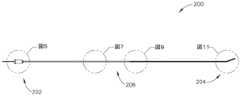
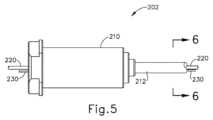
図4は、ガイドワイヤ(30)の代わりに拡張器具アセンブリ(10)に組み込まれ得る例示的な代替のガイドワイヤ(200)を示す。以下に別途記載される場合を除き、ガイドワイヤ(200)は、ガイドワイヤ(30)と同様に構成され、動作可能であり得る。ガイドワイヤ(200)は、拡張器具アセンブリ(10)に対するIGSナビゲーションシステム(100)の適合性を提供するように構成されている。したがって、ガイドワイヤ(200)は、以下に別途記載される場合を除き、ナビゲーションガイドワイヤ(130)と同様に構成され、動作可能であり得ることが理解されるべきである。III. Exemplary Alternative Guidewires FIG. 4 shows an exemplary alternative guidewire (200) that may be incorporated into dilator assembly (10) in place of guidewire (30). Except as otherwise described below, guidewire (200) may be configured and operable similarly to guidewire (30). Guidewire (200) is configured to provide compatibility of IGS navigation system (100) to dilator assembly (10). Accordingly, it should be understood that guidewire (200) may be configured and operable similarly to navigational guidewire (130), except as otherwise described below.
本実施例のガイドワイヤ(200)は、近位端(202)、遠位端(204)、及び端部(202、204)の間に延在する中間領域(206)を有する。図5~図6で最も良く分かるように、ガイドワイヤ(200)の近位部分は、連結部材(210)及び管状部材(212)を含む。連結部材(210)は、IGSナビゲーションシステム(100)の一部分と連結するように構成されている。例えば、連結部材(210)は、プロセッサ(110)を含むコンソールアセンブリと連結するように構成されてもよい。いくつかの他の変形形態では、連結部材(210)は、ガイドワイヤスライダ(24)及びガイドワイヤスピナー(26)と連結するように構成されている。本明細書の教示を考慮することで、連結部材(210)を連結可能な他の構造が当業者に明らかであろう。加えて、本実施例の連結部材(210)は、環状フランジを有する円筒状本体を有するが、本明細書の教示を考慮することで、連結部材(210)に使用され得る他の好適な構成が、当業者には明らかとなろう。 Guidewire (200) of the present example has a proximal end (202), a distal end (204), and an intermediate region (206) extending between ends (202, 204). As best seen in FIGS. 5-6, the proximal portion of guidewire (200) includes a coupling member (210) and a tubular member (212). Coupling member (210) is configured to couple with a portion of IGS navigation system (100). For example, coupling member (210) may be configured to couple with a console assembly that includes processor (110). In some other variations, coupling member (210) is configured to couple with guidewire slider (24) and guidewire spinner (26). Other structures to which coupling member (210) can be coupled will be apparent to those skilled in the art in light of the teachings herein. Additionally, although coupling member (210) of the present example has a cylindrical body with an annular flange, other suitable configurations may be used for coupling member (210) in light of the teachings herein. will be apparent to those skilled in the art.
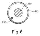
管状部材(212)は、連結部材(210)から遠位方向に延在する。単に一例として、管状部材(212)は、ガイドワイヤ(200)に押し込み能力を提供するように構成された半可撓性ステンレス鋼ケーブル管で形成され得る。更に単に一例として、管状部材(212)は、約0.0345インチの外径及び約0.0225インチの内径を有し得る。あるいは、任意の他の好適な寸法を用いてもよい。いくつかの変形例では、管状部材(212)は、可撓性ポリマー材料で作製される。本明細書の教示を考慮することで、管状部材(212)の形成に使用可能な様々な好適な材料が、当業者に明らかとなろう。図6で最も良く分かるように、センサワイヤ(220)及び接地ワイヤ(230)は、管状部材(212)内に位置付けられている。センサワイヤ(220)は、以下でより詳細に記載される、センサコイル(222)から、IGSナビゲーションシステム(100)に信号を通信するように構成されている。したがって、センサワイヤ(220)は、センサコイル(222)及びIGSナビゲーションシステム(100)と通信していることが理解されるべきである。本実施例では、センサワイヤ(220)は、約0.022インチの外径を有する。接地ワイヤ(230)は、ガイドワイヤ(200)の導電性構成要素の電気接地を提供するように構成されており、これは、センサワイヤ(220)に沿って通信される信号における干渉を実質的に防止することができる。接地ワイヤ(230)の近位端は、IGSナビゲーションシステム(100)又は任意の他の好適な電気接地源と連結され得る。接地ワイヤ(230)の遠位端は、以下により詳細に記載される、はんだ接合部(214)と連結される。 A tubular member (212) extends distally from coupling member (210). Solely by way of example, tubular member (212) may be formed of a semi-flexible stainless steel cable tube configured to provide pushability to guidewire (200). Further by way of example only, tubular member (212) may have an outer diameter of approximately 0.0345 inches and an inner diameter of approximately 0.0225 inches. Alternatively, any other suitable dimensions may be used. In some variations, tubular member (212) is made of a flexible polymeric material. Various suitable materials that can be used to form tubular member (212) will be apparent to those skilled in the art in view of the teachings herein. As best seen in FIG. 6, sensor wires (220) and ground wires (230) are positioned within tubular member (212). Sensor wires (220) are configured to communicate signals from sensor coils (222), described in more detail below, to IGS navigation system (100). It should therefore be understood that the sensor wires (220) are in communication with the sensor coils (222) and the IGS navigation system (100). In the present example, sensor wire (220) has an outer diameter of approximately 0.022 inches. Ground wire (230) is configured to provide an electrical ground for the conductive components of guidewire (200), which substantially prevents interference in signals communicated along sensor wire (220). can be prevented. The proximal end of ground wire (230) may be coupled to IGS navigation system (100) or any other suitable source of electrical ground. The distal end of the ground wire (230) is coupled with a solder joint (214), described in more detail below.
図7~図8は、ガイドワイヤ(200)の中間領域(206)の第1の部分を示す。管状部材(212)は、この部分の全長に沿って延在する。センサワイヤ(220)及び接地ワイヤ(230)もまた、この部分の全長に沿って延在する。コアワイヤ(240)は、この部分において管状部材(212)に固定される。詳細には、コアワイヤ(240)の近位端は、管状部材(212)の内壁に固定される。コアワイヤ(240)は、コアワイヤ(240)がそれに沿って延在するガイドワイヤ(200)の領域に強度を与える非伸縮性材料(例えば、ニチノール)で形成される。特に、コアワイヤ(240)は、コアワイヤ(240)が延在する長さに沿ってガイドワイヤ(200)が長手方向に伸張することを防止する。コアワイヤ(240)はこの実施例では非伸縮性であるが、コアワイヤ(240)は可撓性である。更に、コアワイヤアセンブリ(240)の近位端及び遠位端以外の、コアワイヤ(240)の中間領域は、ガイドワイヤ(200)内にしっかりと固定されてはいない。よって、コアワイヤ(240)は、ガイドワイヤ(200)の横方向の可撓性に悪影響を及ぼさない。本明細書の教示を考慮することで当業者に明らかとなるように、単に一例として、コアワイヤ(240)の近位端は、接着剤を介して、エポキシを介して、又は任意の他の好適な手段若しくは技法を使用して、管状部材(212)の内壁に固定され得る。 Figures 7-8 show a first portion of the intermediate region (206) of the guidewire (200). A tubular member (212) extends along the entire length of this portion. A sensor wire (220) and a ground wire (230) also run along the entire length of this section. Core wire (240) is secured to tubular member (212) at this portion. Specifically, the proximal end of core wire (240) is secured to the inner wall of tubular member (212). Core wire (240) is formed of a non-stretchable material (eg, Nitinol) that provides strength to the region of guidewire (200) along which core wire (240) extends. In particular, corewire (240) prevents longitudinal stretching of guidewire (200) along the length that corewire (240) extends. Core wire (240) is non-stretchable in this example, but core wire (240) is flexible. Additionally, the intermediate region of corewire (240), other than the proximal and distal ends of corewire assembly (240), is not rigidly anchored within guidewire (200). Thus, core wire (240) does not adversely affect the lateral flexibility of guidewire (200). Merely by way of example, the proximal end of core wire (240) may be attached via adhesive, via epoxy, or any other suitable adhesive, as will be apparent to those of ordinary skill in the art in view of the teachings herein. may be secured to the inner wall of tubular member (212) using any means or technique.
図9~図10は、ガイドワイヤ(200)の中間領域(206)の第2の部分を示す。この部分では、管状部材(212)は、はんだ接合部(214)で終端する。近位コイル(250)の近位端(252)もまた、はんだ接合部(214)で終端する。したがって、はんだ接合部(214)は、管状部材(212)を近位コイル(250)と接合する。単に一例として、はんだ接合部(214)は、銀錫はんだで形成され得る。あるいは、任意の他の好適な材料を使用することができる。 Figures 9-10 show a second portion of the intermediate region (206) of the guidewire (200). In this section, tubular member (212) terminates in a solder joint (214). The proximal end (252) of proximal coil (250) also terminates in a solder joint (214). Solder joint (214) thus joins tubular member (212) with proximal coil (250). By way of example only, solder joints (214) may be formed of silver-tin solder. Alternatively, any other suitable material can be used.
本実施例では、近位コイル(250)は、螺旋状構成に巻かれた金属ワイヤ(例えば、ステンレス鋼)で形成される。しかしながら、任意の好適な材料(複数可)及び構成(複数可)を使用して近位コイル(250)を形成し得ることが理解されるべきである。接地ワイヤ(230)の遠位端はまた、はんだ接合部(214)で終端する。したがって、はんだ接合部(214)は、近位コイル(250)から接地ワイヤ(230)への電気接地経路を提供する。図10で最も良く分かるように、センサワイヤ(220)及びコアワイヤ(240)は、図9に示されるガイドワイヤ(200)の領域部分を遠位方向に越え続ける、はんだ接合部(214)を通過する。 In the present example, proximal coil (250) is formed of metal wire (eg, stainless steel) wound in a helical configuration. However, it should be understood that any suitable material(s) and configuration(s) may be used to form proximal coil (250). The distal end of ground wire (230) also terminates in a solder joint (214). Solder joint (214) thus provides an electrical ground path from proximal coil (250) to ground wire (230). As best seen in FIG. 10, sensor wire (220) and core wire (240) pass through solder joint (214) continuing distally over the area portion of guidewire (200) shown in FIG. do.
図11~図12は、ガイドワイヤ(200)の遠位端(204)を示す。近位端(204)は、遠位コイル(260)を含む。本実施例では、遠位コイル(260)は、螺旋状構成に巻かれた金属ワイヤ(例えば、ステンレス鋼)で形成される。しかしながら、任意の好適な材料(複数可)及び構成(複数可)を使用して遠位コイル(260)を形成してもよいことが理解されるべきである。本実施例では、遠位コイル(260)の近位端(262)は、近位コイル(250)の遠位端(254)と接合される。特に、端部(254、262)は、コイル(250、260)の重なり領域が二重螺旋を形成するように、噛合様式で共に接合される。単に一例として、端部(254、262)の噛合領域は、コイル(250、260)の約1~2巻き分に沿って延在し得る。更に単に一例として、端部(254、262)の噛合領域は、約0.5mm~約0.75mmの長さに沿って延在し得る。 Figures 11-12 show the distal end (204) of the guidewire (200). The proximal end (204) includes a distal coil (260). In the present example, distal coil (260) is formed of metal wire (eg, stainless steel) wound in a helical configuration. However, it should be understood that any suitable material(s) and configuration(s) may be used to form distal coil (260). In the present example, proximal end (262) of distal coil (260) is joined with distal end (254) of proximal coil (250). In particular, ends (254, 262) are joined together in an interlocking fashion such that the overlapping regions of coils (250, 260) form a double helix. Merely by way of example, the mating regions of ends (254, 262) may extend along approximately one to two turns of coil (250, 260). Further, by way of example only, the mating regions of ends (254, 262) may extend along a length of about 0.5 mm to about 0.75 mm.
本実施例では、コイル(254、262)は、外径が同じであるが内径が異なっている。単に一例として、コイル(250、260)の両方が、約0.0345インチの外径を有し、近位コイル(250)が約0.0225インチの内径を有し、遠位コイル(260)が約0.0265インチの内径を有し得る。代替的に、他の任意の好適な直径を用いることもできる。また、本実施例において、近位コイル(250)は、約4.5インチの長さを有する。一方、遠位コイル(260)は約4.25mmの長さを有する。あるいは、コイル(250、260)は、任意の他の適切な長さを有してもよい。更に本実施例では、近位コイル(250)は、約0.75mmの開放ピッチを有し、遠位コイル(260)の開放ピッチは、対応する開放ピッチと噛み合うが、任意の他の適切なピッチを使用してもよい。 In the present example, the coils (254, 262) have the same outer diameter but different inner diameters. By way of example only, coils (250, 260) both have an outer diameter of about 0.0345 inches, proximal coil (250) has an inner diameter of about 0.0225 inches, and distal coil (260) has an inner diameter of about 0.0225 inches. may have an inner diameter of about 0.0265 inches. Alternatively, any other suitable diameter can be used. Also, in the present example, proximal coil (250) has a length of approximately 4.5 inches. The distal coil (260), on the other hand, has a length of approximately 4.25 mm. Alternatively, coils (250, 260) may have any other suitable length. Further, in the present example, proximal coil (250) has an open pitch of approximately 0.75 mm, and the open pitch of distal coil (260) mates with a corresponding open pitch, but any other suitable open pitch. Pitch may be used.
また、本実施例において、はんだのリング(292)をコイル(250、260)の噛合領域に適用して、コイル(250、260)の噛合領域を更に一緒に固定する。単に一例として、はんだのリング(292)は銀錫はんだで形成され得る。あるいは、任意の他の好適な材料を使用することができる。 Also in the present example, a ring of solder (292) is applied to the mating regions of coils (250, 260) to further secure the mating regions of coils (250, 260) together. Merely by way of example, solder ring (292) may be formed of silver-tin solder. Alternatively, any other suitable material can be used.
図11~図13にも示されるように、近位コイル(250)は、端部(252、254)間に形成された、事前形成された屈曲部(256)を含む。屈曲部(256)は、ENT外科処置に使用されるガイドワイヤの技術分野において既知の屈曲角度に従って所定の角度で折り曲げることができる。図13で最も良く分かるように、コアワイヤ(240)は、屈曲部(256)の長さに沿って延在する。図13でも分かるように、コアワイヤ(240)は、屈曲部(256)の直近位でテーパ状である。詳細には、コアワイヤ(240)は、遠位領域(246)の外径よりも大きい外径を有する近位領域(242)と、屈曲部(256)に沿ってこれらの外径の間に滑らかな移行をもたらすテーパ領域(244)とを有する。単に一例として、近位領域(242)は、約0.0095インチ、又は約0.10インチの外径を有し得る。更に単に一例として、遠位領域(246)は、約0.0027インチの厚さに平坦化することができる。テーパ領域(244)に沿って使用できる様々な適切な直径、厚さ、及びテーパ角度が、本明細書の教示を考慮することで当業者には明らかとなろう。 As also shown in FIGS. 11-13, proximal coil (250) includes a preformed bend (256) formed between ends (252, 254). Bend (256) may be bent at an angle according to bend angles known in the art for guidewires used in ENT surgical procedures. As best seen in FIG. 13, core wire (240) extends along the length of bend (256). As can also be seen in FIG. 13, core wire (240) tapers just proximal to bend (256). Specifically, core wire (240) has a proximal region (242) having an outer diameter greater than that of distal region (246) and a smooth wire between these outer diameters along bends (256). and a tapered region (244) that provides a smooth transition. Solely by way of example, proximal region (242) may have an outer diameter of about 0.0095 inches, or about 0.10 inches. Further by way of example only, distal region (246) may be flattened to a thickness of approximately 0.0027 inches. Various suitable diameters, thicknesses, and taper angles that can be used along tapered region (244) will be apparent to those of ordinary skill in the art in view of the teachings herein.
屈曲部(256)に沿った遠位領域(246)の直径(又は平坦化)の低減は、コアワイヤ(240)による屈曲部(256)の屈曲角度の達成を容易にし得ることが理解されるべきである。また、遠位コイル(260)の拡大内径と併せて、遠位領域(246)の外径(又は平坦化)の低減は、コアワイヤ(240)の遠位端(248)を遠位コイル(260)内のはんだのリング(292)によって固定し、以下に記載されるようなセンサ(222)を収容することを可能にするのに十分な隙間を提供することも理解されるべきである。 It should be appreciated that reducing the diameter (or flattening) of distal region (246) along bend (256) may facilitate achieving the bend angle of bend (256) by core wire (240). is. Also, the reduction in the outer diameter (or flattening) of distal region (246), in conjunction with the enlarged inner diameter of distal coil (260), allows the distal end (248) of core wire (240) to be closer to distal coil (260). ), providing sufficient clearance to allow accommodation of a sensor (222) as described below.
図12で最も良く分かるように、センサ(222)は、センサワイヤ(220)の遠位端に位置する。本実施例では、センサ(222)は、センサ(222)が電磁場内で運動する際に信号を生成するように構成された単軸コイルを備える。したがって、センサ(222)は、IGSナビゲーションシステム(100)と協働して、ガイドワイヤ(200)の遠位端(204)に関する位置データを提供するように構成されている。センサ(222)に組み込むことのできる様々な好適な構成要素及び構成は、本明細書の教示を考慮することで当業者には明らかとなろう。本実施例では、センサ(222)は、センサ(222)が遠位コイル(260)内に位置するように位置付けられる。詳細には、接着剤(290)を使用して、センサ(222)の外径を遠位コイル(260)の内径に固定する。図示される実施例では、接着剤(290)の近位端は、はんだのリング(292)の遠位端に隣接して位置付けられる。しかしながら、任意の他の好適な空間的関係を使用することができることが理解されるべきである。 As best seen in FIG. 12, sensor (222) is located at the distal end of sensor wire (220). In the present example, sensor (222) comprises a uniaxial coil configured to generate a signal as sensor (222) moves within an electromagnetic field. Accordingly, sensor (222) is configured to cooperate with IGS navigation system (100) to provide position data regarding distal end (204) of guidewire (200). Various suitable components and configurations that can be incorporated into sensor (222) will be apparent to those skilled in the art in view of the teachings herein. In the present example, sensor (222) is positioned such that sensor (222) is located within distal coil (260). Specifically, adhesive (290) is used to secure the outer diameter of sensor (222) to the inner diameter of distal coil (260). In the illustrated example, the proximal end of adhesive (290) is positioned adjacent to the distal end of ring of solder (292). However, it should be understood that any other suitable spatial relationship may be used.
図12にも示されるように、先端部材(280)は、遠位コイル(260)の遠位端(264)に固定されている。先端部材(280)は、本実施例では非外傷性のドーム形状を有する。いくつかの変形形態では、先端部材(280)は接着剤(290)によって形成される。いくつかの他の変形形態では、先端部材(280)は、別個の部品(例えば、ポリマー製)として形成され、次に遠位端(264)に固定され、接着剤(290)に固定されるか、又はセンサ(222)に固定される。先端部材(280)を形成し、かつ固定することができる他の好適な方法は、本明細書の教示を考慮することで当業者には明らかとなるであろう。 As also shown in FIG. 12, tip member (280) is secured to distal end (264) of distal coil (260). Tip member (280) has an atraumatic dome shape in the present example. In some variations, tip member (280) is formed from adhesive (290). In some other variations, tip member (280) is formed as a separate piece (eg, made of a polymer) and then secured to distal end (264) and secured to adhesive (290). or fixed to the sensor (222). Other suitable methods by which tip member (280) may be formed and secured will be apparent to those skilled in the art in view of the teachings herein.
いくつかの変形形態では、ガイドワイヤ(200)の長さの少なくとも一部分(例えば、約7インチ)は、1つ又は2つ以上の材料でコーティングされている。単に一例として、ガイドワイヤ(200)の長さの少なくとも一部分は、シリコーンでコーティングされてもよい。ガイドワイヤ(200)のコーティングとして使用されてもよい他の好適な材料は、本明細書の教示を考慮することで当業者には明らかとなろう。 In some variations, at least a portion (eg, about 7 inches) of the length of guidewire (200) is coated with one or more materials. By way of example only, at least a portion of the length of guidewire (200) may be coated with silicone. Other suitable materials that may be used as a coating for guidewire (200) will be apparent to those of ordinary skill in the art in view of the teachings herein.
IV.例示的な組み合わせ
以下の実施例は、本明細書の教示を組み合わせるか又は適用することができる、様々な非網羅的な方法に関する。以下の実施例は、本出願における又は本出願の後の出願におけるどの時点でも提示され得る、いずれの請求項の適用範囲をも限定することを目的としたものではないと理解されるべきである。一切の棄権を意図するものではない。以下の実施例は、単なる例示の目的で与えられるものにすぎない。本明細書の様々な教示は、他の多くの方法で構成及び適用が可能であると考えられる。また、いくつかの変形例では、以下の実施例において言及される特定の特徴を省略してよいことも考えられる。したがって、本発明者又は本発明者の利益の継承者により、後日、そうである旨が明示的に示されない限り、以下に言及される態様又は特徴のいずれも重要なものとして見なされるべきではない。以下に言及される特徴以外の更なる特徴を含む請求項が本出願において、又は本出願に関連する後の出願において示される場合、それらの更なる特徴は、特許性に関連するいかなる理由によっても追加されたものとして仮定されるべきではない。IV. Exemplary Combinations The following examples relate to various non-exhaustive ways in which the teachings herein can be combined or applied. It should be understood that the following examples are not intended to limit the scope of any claim, which may be presented at any time in this application or in any subsequent application after this application. . No waiver is intended. The following examples are given for illustrative purposes only. It is believed that the various teachings herein can be arranged and applied in many other ways. It is also contemplated that certain variations referred to in the examples below may be omitted in some variations. Accordingly, none of the aspects or features referred to below should be viewed as essential, unless expressly indicated to the contrary at a later date by the inventors or persons succeeding to the interests of the inventors. . If claims containing further features other than those mentioned below appear in this application, or in a subsequent application related to this application, then those further features are for any reason relevant to patentability. It should not be assumed as added.
(実施例1)
装置であって、(a)近位コイルであって、螺旋状構成で巻かれたワイヤによって形成されている、近位コイルと、(b)遠位コイルであって、螺旋状構成で巻かれたワイヤによって形成され、遠位コイルの近位部分における少なくとも1つのラップが、近位コイルの遠位部分における少なくとも1つのラップと噛み合い、その結果、近位コイル及び遠位コイルの噛合部分が二重螺旋構成を形成する、遠位コイルと、(c)遠位コイル内に位置するナビゲーションセンサであって、電磁場内の運動に応答して信号を生成するように構成されている、ナビゲーションセンサと、(d)近位コイルを通って延在するワイヤであって、ワイヤが、ナビゲーションセンサと電気的に通信し、その結果、ナビゲーションセンサからの信号を通信するように構成される、ワイヤと、を備える、装置。(Example 1)
A device comprising: (a) a proximal coil formed by a wire wound in a helical configuration; and (b) a distal coil wound in a helical configuration. and at least one wrap on the proximal portion of the distal coil meshes with at least one wrap on the distal portion of the proximal coil such that there are two mating portions of the proximal and distal coils. a distal coil forming a double helix configuration; and (c) a navigation sensor located within the distal coil, the navigation sensor configured to generate a signal in response to movement within the electromagnetic field. , (d) a wire extending through the proximal coil, the wire configured to electrically communicate with the navigation sensor and, as a result, communicate a signal from the navigation sensor; A device comprising:
(実施例2)
近位コイルの近位端に接合された管状部材を更に備え、ワイヤが管状部材を通して更に延在する、実施例1の装置。(Example 2)
2. The apparatus of example 1, further comprising a tubular member joined to the proximal end of the proximal coil, the wire further extending through the tubular member.
(実施例3)
管状部材が金属材料で形成されている、実施例2の装置。(Example 3)
3. The apparatus of example 2, wherein the tubular member is formed of a metallic material.
(実施例4)
コアワイヤを更に備え、コアワイヤは非伸縮性材料で形成され、コアワイヤの近位端が管状部材に固定されている、実施例2又は3の装置。(Example 4)
4. The apparatus of example 2 or 3, further comprising a core wire, the core wire being formed of a non-stretchable material, the proximal end of the core wire being secured to the tubular member.
(実施例5)
コアワイヤの遠位端が遠位コイルに固定されている、実施例4の装置。(Example 5)
5. The device of example 4, wherein the distal end of the core wire is fixed to the distal coil.
(実施例6)
接地ワイヤを更に備え、接地ワイヤが近位コイルに固定され、接地ワイヤは、近位コイルに電気接地を提供するように構成されている、実施例1~5のいずれか1つ又は2つ以上の装置。(Example 6)
6. Any one or more of Examples 1-5, further comprising a ground wire, the ground wire secured to the proximal coil, the ground wire configured to provide an electrical ground to the proximal coil. equipment.
(実施例7)
近位コイルが、予め形成された屈曲部を含み、予め形成された屈曲部は、近位コイルの遠位端の近位に位置している、実施例1~6のいずれか1つ又は2つ以上の装置。(Example 7)
7. Any one or two of Examples 1-6, wherein the proximal coil includes a preformed bend, the preformed bend being located proximal to the distal end of the proximal coil one or more devices.
(実施例8)
コアワイヤを更に備え、コアワイヤは非伸縮性材料で形成され、コアワイヤは、近位コイルの予め形成された屈曲部を通って延在する、実施例7の装置。(Example 8)
8. The apparatus of example 7, further comprising a core wire, the core wire formed of a non-stretchable material, the core wire extending through a preformed bend in the proximal coil.
(実施例9)
コアワイヤが、第1の外径を有する第1の領域と、第2の外径を有する第2の領域と、第1の領域から第2の領域に延在するテーパと、を有する、実施例8の装置。(Example 9)
Examples wherein the core wire has a first region having a first outer diameter, a second region having a second outer diameter, and a taper extending from the first region to the
(実施例10)
第1の外径が、予め形成された屈曲部の近位にある、実施例9の装置。(Example 10)
10. The device of example 9, wherein the first outer diameter is proximal to the preformed bend.
(実施例11)
テーパが、予め形成された屈曲部の近位にある、実施例10の装置。(Example 11)
11. The device of example 10, wherein the taper is proximal to the preformed bend.
(実施例12)
近位コイルが外径を画定し、遠位コイルが外径を画定し、近位コイルの外径が遠位コイルの外径に等しい、実施例1~11のいずれか1つ又は2つ以上の装置。(Example 12)
12. Any one or more of Examples 1-11, wherein the proximal coil defines an outer diameter, the distal coil defines an outer diameter, and the outer diameter of the proximal coil is equal to the outer diameter of the distal coil equipment.
(実施例13)
近位コイルの外径が約0.0345インチであり、遠位コイルの外径が約0.0345インチである、実施例12の装置。(Example 13)
13. The apparatus of Example 12, wherein the outer diameter of the proximal coil is about 0.0345 inches and the outer diameter of the distal coil is about 0.0345 inches.
(実施例14)
近位コイルが内径を画定し、遠位コイルが内径を画定し、遠位コイルの内径が近位コイルの内径よりも大きい、実施例1~13のいずれか1つ又は2つ以上の装置。(Example 14)
The apparatus of any one or more of Examples 1-13, wherein the proximal coil defines an inner diameter, the distal coil defines an inner diameter, and the inner diameter of the distal coil is greater than the inner diameter of the proximal coil.
(実施例15)
近位コイルの内径が約0.0225インチであり、遠位コイルの内径が約0.0265インチである、実施例14の装置。(Example 15)
15. The apparatus of Example 14, wherein the inner diameter of the proximal coil is about 0.0225 inches and the inner diameter of the distal coil is about 0.0265 inches.
(実施例16)
ナビゲーションセンサが単軸コイルを備える、実施例1~15のいずれか1つ又は2つ以上の装置。(Example 16)
16. The apparatus of any one or more of Examples 1-15, wherein the navigation sensor comprises a single axis coil.
(実施例17)
(a)ガイド部材であって、近位コイル及び遠位コイルが、ガイド部材に対して並進するように構成されている、ガイド部材と、(b)近位コイルの周囲に摺動可能に配設された拡張カテーテルであって、膨張可能な拡張器を含む、拡張カテーテルと、を更に備える、実施例1~16のいずれか1つ又は2つ以上に記載の装置。(Example 17)
(a) a guide member, the proximal coil and the distal coil configured to translate relative to the guide member; and (b) slidably disposed about the proximal coil. 17. The apparatus of any one or more of Examples 1-16, further comprising a dilatation catheter mounted thereon, the dilatation catheter including an inflatable dilator.
(実施例18)
装置であって、(a)本体と、(b)本体から遠位方向に延在するガイドと、(c)ガイドに対して摺動可能に配設されたガイドワイヤであって、(i)近位コイルであって、螺旋状構成に巻かれたワイヤによって形成されている、近位コイル、(ii)遠位コイルであって、螺旋状構成で巻かれたワイヤによって形成され、遠位コイルの近位部分における少なくとも1つのラップが、近位コイルの遠位部分における少なくとも1つのラップと噛み合い、その結果、近位コイル及び遠位コイルの噛合部分が二重螺旋構成を形成する、遠位コイル、並びに(iii)遠位コイル内に位置するナビゲーションセンサであって、電磁場内の運動に応答して信号を生成するように構成されている、ナビゲーションセンサ、を備える、ガイドワイヤと、(d)ガイドワイヤに対して摺動可能に配置された拡張カテーテルであって、膨張可能な拡張器を含む、拡張カテーテルと、を備える、装置。(Example 18)
1. A device comprising: (a) a body; (b) a guide extending distally from the body; and (c) a guidewire slidably disposed relative to the guide, comprising: (i) (ii) a proximal coil, formed by wires wound in a helical configuration; (ii) a distal coil, formed by wires wound in a helical configuration; at least one wrap on the proximal portion of the distal coil interlocks with at least one wrap on the distal portion of the proximal coil such that the interlocking portions of the proximal and distal coils form a double helical configuration. (d ) a dilatation catheter slidably disposed relative to the guidewire, the dilatation catheter including an inflatable dilator.
(実施例19)
ナビゲーションセンサと通信する画像誘導システムを更に備え、画像誘導システムは、患者に対するナビゲーションセンサの位置の表示で画像をレンダリングするように構成されている、実施例18の装置。(Example 19)
19. The apparatus of example 18, further comprising an image guidance system in communication with the navigation sensor, the image guidance system configured to render an image with an indication of the position of the navigation sensor relative to the patient.
(実施例20)
装置であって、(a)近位コイルであって、螺旋状構成で巻かれたワイヤによって形成され、近位コイルの遠位端の近位に位置する屈曲領域を有する、近位コイルと、(b)遠位コイルであって、螺旋状構成で巻かれたワイヤによって形成され、遠位コイルの近位部分における少なくとも1つのラップが、近位コイルの遠位部分における少なくとも1つのラップと噛み合い、その結果、近位コイル及び遠位コイルの噛合部分が二重螺旋構成を形成する、遠位コイルと、(c)近位コイルを通って延在するコアワイヤであって、第1の外径を有する第1の領域、第2の外径を有する第2の領域、及び第1の領域から第2の領域に延在するテーパを有し、第1の外径は、予め形成された屈曲部の近位にある、コアワイヤと、を備える、装置。(Example 20)
1. An apparatus comprising: (a) a proximal coil formed by wire wound in a helical configuration and having a bend region located proximal to a distal end of the proximal coil; (b) a distal coil formed by wire wound in a helical configuration, wherein at least one wrap on the proximal portion of the distal coil meshes with at least one wrap on the distal portion of the proximal coil; (c) a core wire extending through the proximal coil, the core wire having a first outer diameter; a second region having a second outer diameter; and a taper extending from the first region to the second region, the first outer diameter having a preformed bend and a core wire proximal to the portion.
(実施例21)
実施例1~17のいずれか1つ又は2つ以上の装置を使用する方法であって、(a)装置の遠位部分を患者の頭部に挿入することであって、遠位部分は、遠位コイル及びナビゲーションセンサを含む、挿入することと、(b)患者の頭部の周囲で電磁場を作動させることと、(c)電磁場内のナビゲーションセンサの運動に応答して生成された信号に基づいて、ナビゲーションセンサの運動を追跡することと、を含む、方法。(Example 21)
A method of using the device of any one or more of Examples 1-17, comprising: (a) inserting a distal portion of the device into a patient's head, the distal portion comprising: (b) activating an electromagnetic field about the patient's head; and (c) a signal generated in response to movement of the navigation sensor within the electromagnetic field. tracking movement of a navigation sensor based on the method.
(実施例22)
(a)拡張器を装置の遠位部分に沿って前進させて、拡張器を患者の頭部内の解剖学的通路内に位置付けることと、(b)拡張器を拡張し、それによって解剖学的通路を膨張させることと、を更に含む、実施例21の方法。(Example 22)
(a) advancing the dilator along the distal portion of the device to position the dilator within an anatomical passageway within the patient's head; 22. The method of example 21, further comprising inflating the target passageway.
(実施例23)
解剖学的通路が、副鼻腔口、前頭陥凹、又は耳管からなる群から選択されている、実施例22の方法。(Example 23)
23. The method of example 22, wherein the anatomical passageway is selected from the group consisting of sinus ostia, frontal depressions, or eustachian tubes.
(実施例24)
実施例18又は19の装置を使用する方法であって、(a)患者の頭部の周囲に電磁場を発生させることと、(b)ガイドの遠位部分を患者の頭部内に挿入することと、(c)ガイドワイヤをガイドに対して遠位方向に前進させ、それによって遠位コイル及びナビゲーションセンサを患者の頭部内に位置付けることと、(d)電磁場内のナビゲーションセンサの運動に応答して発生された信号に基づいて、ナビゲーションセンサの運動を追跡することと、を含む、方法。(Example 24)
A method of using the apparatus of Examples 18 or 19 comprising: (a) generating an electromagnetic field around the patient's head; and (b) inserting the distal portion of the guide into the patient's head. (c) advancing the guidewire distally relative to the guide, thereby positioning the distal coil and navigation sensor within the patient's head; and (d) responding to movement of the navigation sensor within the electromagnetic field. and tracking movement of the navigation sensor based on signals generated by the method.
(実施例25)
(a)拡張器をガイドワイヤに沿って前進させて、拡張器を患者の頭部内の解剖学的通路内に位置付けることと、(b)拡張器を拡張し、それによって解剖学的通路を拡張することと、を更に含む、実施例24の方法。(Example 25)
(a) advancing the dilator along the guidewire to position the dilator within the anatomical passageway within the patient's head; and (b) expanding the dilator thereby closing the anatomical passageway. 25. The method of example 24, further comprising expanding.
(実施例26)
解剖学的通路が、副鼻腔口、前頭陥凹、又は耳管からなる群から選択されている、実施例25の方法。(Example 26)
26. The method of example 25, wherein the anatomical passageway is selected from the group consisting of sinus ostia, frontal depressions, or eustachian tubes.
(実施例27)
実施例20の装置を使用する方法であって、装置の遠位部分を患者の頭部内に挿入することを含み、遠位部分は遠位コイルを含む、方法。(Example 27)
21. A method of using the device of example 20, comprising inserting a distal portion of the device into a patient's head, the distal portion including a distal coil.
(実施例28)
(a)拡張器を装置の遠位部分に沿って前進させて、拡張器を患者の頭部内の解剖学的通路内に位置付けることと、(b)拡張器を拡張し、それによって解剖学的通路を拡張することと、を更に含む、実施例27の方法。(Example 28)
(a) advancing the dilator along the distal portion of the device to position the dilator within an anatomical passageway within the patient's head; 28. The method of example 27, further comprising expanding the target passageway.
(実施例29)
解剖学的通路が、副鼻腔口、前頭陥凹、又は耳管からなる群から選択されている、実施例29の方法。(Example 29)
30. The method of example 29, wherein the anatomical passageway is selected from the group consisting of sinus ostia, frontal depressions, or eustachian tubes.
V.その他
本明細書に記載の実施例のうちのいずれも、上述のものに加えて又はそれに代えて、様々な他の特徴を含み得る点が理解されるべきである。単に一例として、本明細書に記載の実施例のうちのいずれも、参照により本明細書に組み込まれる様々な参考文献のいずれかに開示されている様々な特徴のうちの1つ又は2つ以上を含むこともできる。V. Miscellaneous It should be understood that any of the embodiments described herein can include various other features in addition to or in place of those described above. Solely by way of example, any of the embodiments described herein may be used in conjunction with one or more of the various features disclosed in any of the various references incorporated herein by reference. can also include
本明細書に記載の教示、表現、実施形態、実施例などのうちのいずれか1つ又は2つ以上を、本明細書に記載の他の教示、表現、実施形態、実施例などのうちのいずれか1つ又は2つ以上と組み合わせることができる点が理解されるべきである。したがって、上記の教示、表現、実施形態、実施例などは、互いに対して独立して考慮されるべきではない。本明細書の教示に照らして、本明細書の教示を組み合わせることができる様々な好適な方法が、当業者には容易に明らかとなろう。このような修正及び変形例は、「特許請求の範囲」内に含まれるものとする。 Any one or more of the teachings, expressions, embodiments, examples, etc. described herein may be combined with other teachings, expressions, embodiments, examples, etc. described herein. It should be understood that any one or more may be combined. Accordingly, the above teachings, expressions, embodiments, examples, etc. should not be considered independently of each other. Various suitable ways in which the teachings herein can be combined will be readily apparent to those skilled in the art in light of the teachings herein. Such modifications and variations are intended to be included within the scope of the claims.
本明細書に参照により組み込まれると言及されるいかなる特許、公報、又はその他の開示内容も、全体的に又は部分的に、組み込まれる内容が現行の定義、見解、又は本開示に記載されるその他の開示内容とあくまで矛盾しない範囲でのみ本明細書に組み込まれると理解されるべきである。そのようなものであるから、また必要な範囲で、本明細書に明瞭に記載される開示内容は、参考により本明細書に組み込まれるあらゆる矛盾する記載に優先するものとする。現行の定義、見解、又は本明細書に記載されたその他の開示内容と矛盾する任意の内容、又はそれらの部分は本明細書に参考として組み込まれるものとするが、参照内容と現行の開示内容との間に矛盾が生じない範囲においてのみ、参照されるものとする。 Any patents, publications, or other disclosures referred to as being incorporated herein by reference are, in whole or in part, subject to the current definitions, opinions, or other statements set forth in this disclosure. should be understood to be incorporated herein only to the extent not inconsistent with the disclosure of . As such, and to the extent necessary, the disclosure as explicitly set forth herein supersedes any conflicting statements incorporated herein by reference. Any content, or portion thereof, that conflicts with the current definitions, opinions, or other disclosures set forth herein, is hereby incorporated by reference, but the reference content and the current disclosure are hereby incorporated by reference. References shall be made only to the extent that there is no inconsistency between
本明細書に開示されるデバイスの変形形態は、1回の使用後に処分されるように設計するか又は複数回使用されるように設計することができる。変形形態は、いずれか又は両方の場合においても、少なくとも1回の使用後に再利用のために再調整され得る。再調整は、デバイスの分解工程、それに続く特定の部品の洗浄又は交換工程、及びその後の再組み立て工程の、任意の組み合わせを含み得る。詳細には、デバイスの変形形態は分解されてもよく、また、デバイスの任意の数の特定の部分又は部品を任意の組み合わせで選択的に交換又は取り外すことができる。特定の部品を洗浄及び/又は交換した後、デバイスの変形形態は、再調整用の施設において、又は外科処置の直前に外科チームのいずれかによって、その後の使用のために再組み立てすることができる。当業者であれば、デバイスの再調整において、分解、洗浄/交換、及び再組み立てのための様々な技術を利用することができることを理解するであろう。このような技術の使用、及び結果として得られる再調整されたデバイスは、全て本出願の範囲内にある。 Variations of the devices disclosed herein can be designed to be disposed of after a single use or can be designed to be used multiple times. The variant can be reconditioned for reuse after at least one use in either or both cases. Reconditioning may involve any combination of the steps of disassembly of the device, followed by cleaning or replacement of particular parts, and subsequent reassembly. In particular, variations of the device may be disassembled, and any number of the particular parts or parts of the device may be selectively replaced or removed in any combination. After cleaning and/or replacing certain parts, the device variations can be reassembled for subsequent use either at a reconditioning facility or by a surgical team immediately prior to a surgical procedure. . Those skilled in the art will appreciate that reconditioning of the device can utilize a variety of techniques for disassembly, cleaning/replacement, and reassembly. Use of such techniques, and the resulting reconditioned device, are all within the scope of the present application.
単に一例としてではあるが、本明細書に記載の変形形態は手術に先立って処理することができる。まず、新品又は使用済みの器具を入手し、必要に応じて洗浄することができる。次いで、器具を滅菌してよい。1つの滅菌技術では、器具は、プラスチックバッグ又はTYVEKバッグなどの、閉鎖され密封された容器に入れられる。次いで、容器及び器具を、γ線、X線、又は高エネルギー電子などの容器を透過し得る放射線野に置くことができる。放射線は、器具上及び容器内の細菌を死滅させることができる。次いで、滅菌済みの器具を滅菌容器内で保管してよい。密封容器は、手術設備で開封されるまで器具を滅菌状態に保つことができる。β線若しくはγ線、エチレンオキシド、又は水蒸気が挙げられるがこれらに限定されない、当該技術分野で既知のその他の任意の技術を用いて、デバイスを滅菌してもよい。 By way of example only, the variations described herein can be processed prior to surgery. First, a new or used instrument can be obtained and cleaned as needed. The instrument may then be sterilized. In one sterilization technique, the instrument is placed in a closed and sealed container, such as a plastic bag or TYVEK bag. The container and instrument can then be placed in a radiation field that can penetrate the container, such as gamma rays, X-rays, or high-energy electrons. Radiation can kill bacteria on the device and in the container. The sterilized instrument may then be stored in the sterile container. The sealed container can keep the instrument sterile until it is opened in the surgical facility. Any other technique known in the art may be used to sterilize the device, including but not limited to beta or gamma radiation, ethylene oxide, or steam.
本発明の様々な変形形態について図示し説明したが、本明細書に記載の方法及びシステムの更なる応用が、当業者による適切な改変により、本発明の範囲から逸脱することなく実現可能である。そのような可能な改変のうちのいくつかについて述べたが、他の改変も当業者には明らかとなるであろう。例えば、上述の実施例、変形形態、幾何学形状、材料、寸法、比率、工程などは例示的なものであって、必須ではない。したがって、本発明の範囲は、以下の特許請求の範囲の観点から考慮されるべきものであり、本明細書及び図面に示され記載された構造及び動作の細部に限定されないものとして理解される。 While various variations of the invention have been illustrated and described, further applications of the methods and systems described herein can be realized by suitable modifications by those skilled in the art without departing from the scope of the invention. . While some of such possible modifications have been mentioned, others will become apparent to those skilled in the art. For example, the examples, variations, geometries, materials, dimensions, proportions, steps, etc. described above are exemplary and not required. Accordingly, the scope of the present invention should be considered in light of the following claims and understood not to be limited to the details of construction and operation shown and described in the specification and drawings.
〔実施の態様〕
(1) 装置であって、
(a)近位コイルであって、螺旋状構成で巻かれたワイヤによって形成されている、近位コイルと、
(b)遠位コイルであって、螺旋状構成で巻かれたワイヤによって形成され、前記遠位コイルの近位部分における少なくとも1つのラップが、前記近位コイルの遠位部分における少なくとも1つのラップと噛み合い、その結果、前記近位コイル及び前記遠位コイルの噛合部分が二重螺旋構成を形成する、遠位コイルと、
(c)前記遠位コイル内に位置するナビゲーションセンサであって、電磁場内の運動に応答して信号を発生させるように構成されている、ナビゲーションセンサと、
(d)前記近位コイルを通って延在するワイヤであって、前記ナビゲーションセンサと電気的に通信し、その結果、前記ナビゲーションセンサからの信号を通信するように構成されている、ワイヤと、を備える、装置。
(2) 前記近位コイルの近位端に接合された管状部材を更に備え、前記ワイヤが前記管状部材を通って更に延在する、実施態様1に記載の装置。
(3) 前記管状部材が金属材料で形成されている、実施態様2に記載の装置。
(4) コアワイヤを更に備え、前記コアワイヤは非伸縮性材料で形成され、前記コアワイヤの近位端が前記管状部材に固定されている、実施態様2に記載の装置。
(5) 前記コアワイヤの遠位端が前記遠位コイルに固定されている、実施態様4に記載の装置。[Mode of implementation]
(1) A device comprising:
(a) a proximal coil, the proximal coil being formed by a wire wound in a helical configuration;
(b) a distal coil formed by a wire wound in a helical configuration, wherein at least one wrap on a proximal portion of said distal coil comprises at least one wrap on a distal portion of said proximal coil; so that the mating portions of said proximal coil and said distal coil form a double helical configuration;
(c) a navigation sensor located within the distal coil, the navigation sensor configured to generate a signal in response to motion within an electromagnetic field;
(d) a wire extending through the proximal coil, the wire being configured to electrically communicate with the navigation sensor and, as a result, communicate a signal from the navigation sensor; A device comprising:
Aspect 2. The device of aspect 1, further comprising a tubular member joined to the proximal end of the proximal coil, the wire further extending through the tubular member.
(3) The apparatus of aspect 2, wherein the tubular member is formed of a metallic material.
4. The apparatus of claim 2, further comprising a core wire, said core wire being formed of a non-stretchable material, and a proximal end of said core wire being secured to said tubular member.
(5) The apparatus of claim 4, wherein a distal end of said core wire is fixed to said distal coil.
(6) 接地ワイヤを更に備え、前記接地ワイヤは前記近位コイルに固定され、前記接地ワイヤは、前記近位コイルに電気接地を提供するように構成されている、実施態様1に記載の装置。
(7) 前記近位コイルが、予め形成された屈曲部を含み、前記予め形成された屈曲部は、前記近位コイルの遠位端の近位に位置している、実施態様1に記載の装置。
(8) コアワイヤを更に備え、前記コアワイヤは非伸縮性材料で形成され、前記コアワイヤは、前記近位コイルの前記予め形成された屈曲部を通って延在する、実施態様7に記載の装置。
(9) 前記コアワイヤが、第1の外径を有する第1の領域と、第2の外径を有する第2の領域と、前記第1の領域から前記第2の領域に延在するテーパと、を有する、実施態様8に記載の装置。
(10) 前記第1の外径が、前記予め形成された屈曲部の近位にある、実施態様9に記載の装置。
Aspect 7. Aspect 1, wherein the proximal coil comprises a pre-formed bend, the pre-formed bend being located proximal to the distal end of the proximal coil. Device.
(9) the core wire has a first region having a first outer diameter; a second region having a second outer diameter; and a taper extending from the first region to the second region. 9. An apparatus according to
10. The apparatus of claim 9, wherein said first outer diameter is proximal to said preformed bend.
(11) 前記テーパが、前記予め形成された屈曲部の近位にある、実施態様10に記載の装置。
(12) 前記近位コイルが外径を画定し、前記遠位コイルが外径を画定し、前記近位コイルの前記外径が前記遠位コイルの前記外径に等しい、実施態様1に記載の装置。
(13) 前記近位コイルの前記外径が約0.8763mm(約0.0345インチ)であり、前記遠位コイルの前記外径が約0.8763mm(約0.0345インチ)である、実施態様12に記載の装置。
(14) 前記近位コイルが内径を画定し、前記遠位コイルが内径を画定し、前記遠位コイルの前記内径が前記近位コイルの前記内径よりも大きい、実施態様1に記載の装置。
(15) 前記近位コイルの前記内径が約0.5715mm(約0.0225インチ)であり、前記遠位コイルの前記内径が約0.6731mm(約0.0265インチ)である、実施態様14に記載の装置。11. The apparatus of
(13) Practice wherein the outer diameter of the proximal coil is about 0.0345 inches and the outer diameter of the distal coil is about 0.0345 inches. 13. Apparatus according to
15.
(16) 前記ナビゲーションセンサが単軸コイルを備える、実施態様1に記載の装置。
(17) (a)ガイド部材であって、前記近位コイル及び前記遠位コイルが、前記ガイド部材に対して並進するように構成されている、ガイド部材と、
(b)前記近位コイルの周囲に摺動可能に配設された拡張カテーテルであって、膨張可能な拡張器を含む、拡張カテーテルと、を更に備える、実施態様1に記載の装置。
(18) 装置であって、
(a)本体と、
(b)前記本体から遠位方向に延在するガイドと、
(c)前記ガイドに対して摺動可能に配設されたガイドワイヤであって、
(i)近位コイルであって、螺旋状構成で巻かれたワイヤによって形成されている、近位コイル、
(ii)遠位コイルであって、螺旋状構成で巻かれたワイヤによって形成され、前記遠位コイルの近位部分における少なくとも1つのラップが、前記近位コイルの遠位部分における少なくとも1つのラップと噛み合い、その結果、前記近位コイル及び前記遠位コイルの噛合部分が二重螺旋構成を形成する、遠位コイル、並びに
(iii)前記遠位コイル内に位置するナビゲーションセンサであって、電磁場内の運動に応答して信号を発生させるように構成されている、ナビゲーションセンサ、を備える、ガイドワイヤと、
(d)前記ガイドワイヤに対して摺動可能に配置された拡張カテーテルであって、膨張可能な拡張器を含む、拡張カテーテルと、
を備える、装置。
(19) 前記ナビゲーションセンサと通信する画像誘導システムを更に備え、前記画像誘導システムは、患者に対する前記ナビゲーションセンサの位置の表示で画像をレンダリングするように構成されている、実施態様18に記載の装置。
(20) 装置であって、
(a)近位コイルであって、螺旋状構成で巻かれたワイヤによって形成され、前記近位コイルの遠位端の近位に位置する屈曲領域を有する、近位コイルと、
(b)遠位コイルであって、螺旋状構成で巻かれたワイヤによって形成され、前記遠位コイルの近位部分における少なくとも1つのラップが、前記近位コイルの遠位部分における少なくとも1つのラップと噛み合い、その結果、前記近位コイル及び前記遠位コイルの噛合部分が二重螺旋構成を形成する、遠位コイルと、
(c)前記近位コイルを通って延在するコアワイヤであって、第1の外径を有する第1の領域、第2の外径を有する第2の領域、及び前記第1の領域から前記第2の領域に延在するテーパを有し、前記第1の外径は、前記予め形成された屈曲部の近位にある、コアワイヤと、を備える、装置。
(17) (a) a guide member, wherein the proximal coil and the distal coil are configured to translate relative to the guide member;
(b) a dilatation catheter slidably disposed about the proximal coil, the dilatation catheter including an inflatable dilator;
(18) A device comprising:
(a) a body;
(b) a guide extending distally from the body;
(c) a guide wire slidably disposed relative to the guide,
(i) a proximal coil formed by a wire wound in a helical configuration;
(ii) a distal coil formed by wire wound in a helical configuration, wherein at least one wrap on a proximal portion of said distal coil comprises at least one wrap on a distal portion of said proximal coil; so that the mating portions of said proximal coil and said distal coil form a double helical configuration; and (iii) a navigation sensor located within said distal coil, said navigation sensor comprising an electromagnetic field a guidewire comprising a navigation sensor configured to generate a signal in response to movement within;
(d) a dilatation catheter slidably disposed relative to the guidewire, the dilatation catheter including an inflatable dilator;
A device comprising:
Aspect 19. The apparatus of aspect 18, further comprising an image guidance system in communication with the navigation sensor, the image guidance system configured to render an image with an indication of the position of the navigation sensor relative to the patient. .
(20) A device comprising:
(a) a proximal coil formed by wire wound in a helical configuration and having a bend region located proximal to a distal end of said proximal coil;
(b) a distal coil formed by a wire wound in a helical configuration, wherein at least one wrap on a proximal portion of said distal coil comprises at least one wrap on a distal portion of said proximal coil; so that the mating portions of said proximal coil and said distal coil form a double helical configuration;
(c) a core wire extending through said proximal coil, said core wire having a first region having a first outer diameter; a second region having a second outer diameter; a core wire having a taper extending into a second region, the first outer diameter being proximal to the preformed bend.
Claims (17)
Translated fromJapanese(a)近位コイルであって、螺旋状構成で巻かれたワイヤによって形成され、内腔を形成している、近位コイルと、
(b)遠位コイルであって、螺旋状構成で巻かれたワイヤによって形成され、前記遠位コイルの近位部分における少なくとも1つのラップが、前記近位コイルの遠位部分における少なくとも1つのラップと噛み合い、その結果、前記近位コイル及び前記遠位コイルの噛合部分が二重螺旋構成を形成する、遠位コイルと、
(c)前記遠位コイル内に位置するナビゲーションセンサであって、電磁場内の運動に応答して信号を発生させるように構成されている、ナビゲーションセンサと、
(d)前記近位コイルの前記内腔を通って延在するセンサワイヤであって、前記ナビゲーションセンサと電気的に通信し、その結果、前記ナビゲーションセンサからの信号を通信するように構成されている、センサワイヤと、を備え、
前記近位コイルが、予め形成された屈曲部を含み、前記予め形成された屈曲部は、前記近位コイルの遠位端の近位に位置しており、
前記装置は前記近位コイルの前記内腔を通って延在するコアワイヤを更に備え、前記コアワイヤは非伸縮性材料で形成され、前記センサワイヤ及び前記コアワイヤは、前記近位コイルの前記予め形成された屈曲部における前記近位コイルの前記内腔を超えて遠位側に延在し、
前記コアワイヤが、第1の外径を有する近位領域と、前記第1の外径より小さい第2の外径を有するか、又は平坦化されている遠位領域と、前記予め形成された屈曲部に沿って前記近位領域と前記遠位領域との間の移行をもたらすテーパ領域と、を有する、装置。a device,
(a) a proximal coil formed by a wire wound in a helical configurationand defining a lumen ;
(b) a distal coil formed by a wire wound in a helical configuration, wherein at least one wrap on a proximal portion of said distal coil comprises at least one wrap on a distal portion of said proximal coil; so that the mating portions of said proximal coil and said distal coil form a double helical configuration;
(c) a navigation sensor located within the distal coil, the navigation sensor configured to generate a signal in response to motion within an electromagnetic field;
(d)a sensor wire extending throughthe lumen of the proximal coil and configured to electrically communicate with the navigation sensor and, as a result, communicate a signal from the navigation sensor;a sensor wire;
said proximal coil comprising a preformed bend, said preformed bend being located proximal to a distal end of said proximal coil;
The device further comprises a core wireextending through the lumen of the proximal coil , the core wire being formed of a non-stretchable material,the sensor wire and the core wire being aligned with the preformed lumen of the proximal coil. extendingdistallybeyondthe lumen of the proximal coil at a bend;
The core wire has a proximal region having a first outer diameter, a distal region having a second outer diameter smaller than the first outer diameter or being flattened, and the preformed bend. and a tapered region providing a transition between the proximal region and the distal region along a section.
(b)前記近位コイルの周囲に摺動可能に配設された拡張カテーテルであって、膨張可能な拡張器を含む、拡張カテーテルと、を更に備える、請求項1に記載の装置。(a) a guide member, wherein the proximal coil and the distal coil are configured to translate relative to the guide member;
2. The apparatus of claim 1, further comprising: (b) a dilatation catheter slidably disposed about the proximal coil, the dilatation catheter including an inflatable dilator.
Applications Claiming Priority (5)
| Application Number | Priority Date | Filing Date | Title |
|---|---|---|---|
| US201762453220P | 2017-02-01 | 2017-02-01 | |
| US62/453,220 | 2017-02-01 | ||
| US15/861,959US10610308B2 (en) | 2017-02-01 | 2018-01-04 | Navigation guidewire with interlocked coils |
| US15/861,959 | 2018-01-04 | ||
| PCT/US2018/016077WO2018144500A1 (en) | 2017-02-01 | 2018-01-31 | Navigation guidewire with interlocked coils |
Publications (2)
| Publication Number | Publication Date |
|---|---|
| JP2020514004A JP2020514004A (en) | 2020-05-21 |
| JP7229940B2true JP7229940B2 (en) | 2023-02-28 |
Family
ID=62977362
Family Applications (1)
| Application Number | Title | Priority Date | Filing Date |
|---|---|---|---|
| JP2019562224AActiveJP7229940B2 (en) | 2017-02-01 | 2018-01-31 | Navigation guidewire with mating coil |
Country Status (9)
| Country | Link |
|---|---|
| US (1) | US10610308B2 (en) |
| EP (1) | EP3576602B1 (en) |
| JP (1) | JP7229940B2 (en) |
| KR (1) | KR20190112094A (en) |
| CN (1) | CN110248589A (en) |
| AU (1) | AU2018217021A1 (en) |
| CA (1) | CA3051858A1 (en) |
| IL (1) | IL268272B (en) |
| WO (1) | WO2018144500A1 (en) |
Families Citing this family (19)
| Publication number | Priority date | Publication date | Assignee | Title |
|---|---|---|---|---|
| US8187307B2 (en) | 2006-10-19 | 2012-05-29 | Simpirica Spine, Inc. | Structures and methods for constraining spinal processes with single connector |
| EP2296567B1 (en) | 2008-06-06 | 2014-03-12 | Simpirica Spine, Inc. | Apparatus for locking a band |
| WO2012048131A2 (en) | 2010-10-06 | 2012-04-12 | Simpirica Spine, Inc. | Device and accessories for limiting flexion |
| US11260208B2 (en) | 2018-06-08 | 2022-03-01 | Acclarent, Inc. | Dilation catheter with removable bulb tip |
| US10322269B1 (en) | 2015-01-19 | 2019-06-18 | Dalent, LLC | Dilator device |
| US11883618B2 (en) | 2018-10-05 | 2024-01-30 | Acclarent, Inc. | Dilation catheter tip removal instrument |
| US11602619B2 (en) | 2018-10-05 | 2023-03-14 | Biosense Webster (Israel) Ltd. | Coupling assembly for variable diameter surgical instrument |
| US11686043B2 (en) | 2018-11-05 | 2023-06-27 | Acclarent, Inc. | Pull wire with coated fibers |
| US11484366B2 (en)* | 2018-11-29 | 2022-11-01 | Acclarent, Inc. | Adapter assembly to enable navigation for ENT instruments |
| US11395906B2 (en)* | 2018-12-12 | 2022-07-26 | Acclarent, Inc. | Combined sinuplasty and seeker instrument with navigation and illumination modalities |
| US11419623B2 (en)* | 2018-12-12 | 2022-08-23 | Acclarent, Inc. | Sinuplasty instrument with moveable navigation sensor |
| US11273293B2 (en) | 2018-12-21 | 2022-03-15 | Acclarent, Inc. | Sinuplasty instrument with deflectable guide rail |
| WO2020195210A1 (en)* | 2019-03-22 | 2020-10-01 | 株式会社カネカ | Endoscopic treatment instrument |
| US11975157B2 (en) | 2019-04-12 | 2024-05-07 | Covidien Lp | Method of manufacturing an elongated catheter having multiple sensors for three-dimensional location of the catheter |
| CN110575603A (en)* | 2019-10-14 | 2019-12-17 | 苏州法兰克曼医疗器械有限公司 | A guidewire delivery device with visual function |
| US11944769B2 (en) | 2019-11-12 | 2024-04-02 | Acclarent, Inc. | Steerable guide with partial sleeve |
| US11944758B2 (en) | 2019-12-16 | 2024-04-02 | Acclarent, Inc. | Atraumatic tip assembly for guidewire |
| CA3220367A1 (en)* | 2021-05-27 | 2022-12-01 | Jonathan Karl Burkholz | Intravenous catheter device having a guidewire for actively repositioning a catheter tip |
| CN118662760B (en)* | 2024-08-22 | 2024-11-22 | 杭州亿科医疗科技有限公司 | Vascular Intervention Guidewire |
Citations (6)
| Publication number | Priority date | Publication date | Assignee | Title |
|---|---|---|---|---|
| JP2002518109A (en) | 1998-06-17 | 2002-06-25 | アドヴァンスト カーディオヴァスキュラー システムズ インコーポレーテッド | Radiopaque composite in-body device |
| JP2007501648A (en) | 2003-08-07 | 2007-02-01 | ブリヴァント リサーチ アンド デベロップメント リミテッド | Guide wire for catheter |
| JP2012205795A (en) | 2011-03-30 | 2012-10-25 | Asahi Intecc Co Ltd | Guide wire |
| JP2014236757A (en) | 2011-09-29 | 2014-12-18 | テルモ・クリニカルサプライ株式会社 | Guide wire |
| JP2015502790A (en) | 2011-11-22 | 2015-01-29 | アセンション テクノロジー コーポレイションAscension Technology Corporation | Tracking guidewire |
| WO2016171940A1 (en) | 2015-04-22 | 2016-10-27 | Acclarent, Inc. | Guidewire with navigation sensor |
Family Cites Families (51)
| Publication number | Priority date | Publication date | Assignee | Title |
|---|---|---|---|---|
| US4538622A (en)* | 1983-11-10 | 1985-09-03 | Advanced Cardiovascular Systems, Inc. | Guide wire for catheters |
| US4676249A (en)* | 1986-05-19 | 1987-06-30 | Cordis Corporation | Multi-mode guidewire |
| US5105818A (en)* | 1987-04-10 | 1992-04-21 | Cardiometric, Inc. | Apparatus, system and method for measuring spatial average velocity and/or volumetric flow of blood in a vessel and screw joint for use therewith |
| US5174295A (en)* | 1987-04-10 | 1992-12-29 | Cardiometrics, Inc. | Apparatus, system and method for measuring spatial average velocity and/or volumetric flow of blood in a vessel and screw joint for use therewith |
| US4830023A (en)* | 1987-11-27 | 1989-05-16 | Medi-Tech, Incorporated | Medical guidewire |
| US4934380A (en)* | 1987-11-27 | 1990-06-19 | Boston Scientific Corporation | Medical guidewire |
| US4922924A (en)* | 1989-04-27 | 1990-05-08 | C. R. Bard, Inc. | Catheter guidewire with varying radiopacity |
| US5282478A (en)* | 1991-08-21 | 1994-02-01 | Baxter International, Inc. | Guidewire extension system with coil connectors |
| US5271415A (en)* | 1992-01-28 | 1993-12-21 | Baxter International Inc. | Guidewire extension system |
| US5377690A (en)* | 1993-02-09 | 1995-01-03 | C. R. Bard, Inc. | Guidewire with round forming wire |
| US6491646B1 (en)* | 1993-03-11 | 2002-12-10 | Lake Region Manufacturing, Inc. | Guidewire extension system |
| US5421348A (en)* | 1993-11-29 | 1995-06-06 | Cordis Corporation | Rotating guidewire extension system with mechanically locking extension wire |
| US5520194A (en)* | 1993-12-07 | 1996-05-28 | Asahi Intecc Co., Ltd. | Guide wire for medical purpose and manufacturing process of coil thereof |
| US5788653A (en)* | 1996-04-03 | 1998-08-04 | Cordis Corporation | Guidewire extension with sliding release mechanism |
| EP0879616A1 (en)* | 1997-05-21 | 1998-11-25 | Schneider (Europe) GmbH | Guide wire |
| JP3426174B2 (en)* | 1999-12-24 | 2003-07-14 | 朝日インテック株式会社 | Medical guidewire |
| US6527732B1 (en)* | 2000-10-17 | 2003-03-04 | Micro Therapeutics, Inc. | Torsionally compensated guidewire |
| JP4497746B2 (en)* | 2001-04-10 | 2010-07-07 | ニプロ株式会社 | Guide wire |
| US7481778B2 (en)* | 2002-03-22 | 2009-01-27 | Cordis Corporation | Guidewire with deflectable tip having improved flexibility |
| US20070219464A1 (en)* | 2002-03-22 | 2007-09-20 | Stephen Davis | Guidewire with deflectable re-entry tip |
| US7077811B2 (en)* | 2002-12-23 | 2006-07-18 | Scimed Life Systems, Inc. | Guidewire tip construction |
| US7462175B2 (en) | 2004-04-21 | 2008-12-09 | Acclarent, Inc. | Devices, systems and methods for treating disorders of the ear, nose and throat |
| US20110004057A1 (en) | 2004-04-21 | 2011-01-06 | Acclarent, Inc. | Systems and methods for transnasal dilation of passageways in the ear, nose or throat |
| US8702626B1 (en) | 2004-04-21 | 2014-04-22 | Acclarent, Inc. | Guidewires for performing image guided procedures |
| US20070208252A1 (en) | 2004-04-21 | 2007-09-06 | Acclarent, Inc. | Systems and methods for performing image guided procedures within the ear, nose, throat and paranasal sinuses |
| US20060063973A1 (en) | 2004-04-21 | 2006-03-23 | Acclarent, Inc. | Methods and apparatus for treating disorders of the ear, nose and throat |
| US7559925B2 (en)* | 2006-09-15 | 2009-07-14 | Acclarent Inc. | Methods and devices for facilitating visualization in a surgical environment |
| US7720521B2 (en) | 2004-04-21 | 2010-05-18 | Acclarent, Inc. | Methods and devices for performing procedures within the ear, nose, throat and paranasal sinuses |
| US8190389B2 (en) | 2006-05-17 | 2012-05-29 | Acclarent, Inc. | Adapter for attaching electromagnetic image guidance components to a medical device |
| US8366720B2 (en)* | 2006-07-31 | 2013-02-05 | Codman & Shurtleff, Inc. | Interventional medical device system having an elongation retarding portion and method of using the same |
| US20080051676A1 (en)* | 2006-08-24 | 2008-02-28 | Melsheimer Jeffry S | Extendable Wire Guide system |
| JP5020630B2 (en)* | 2006-12-28 | 2012-09-05 | テルモ株式会社 | Guide wire |
| US20080183128A1 (en) | 2007-01-24 | 2008-07-31 | John Morriss | Methods, devices and systems for treatment and/or diagnosis of disorders of the ear, nose and throat |
| US8239003B2 (en) | 2007-04-16 | 2012-08-07 | General Electric Company | System and method of integrating electromagnetic microsensors in guidewires |
| US8320711B2 (en) | 2007-12-05 | 2012-11-27 | Biosense Webster, Inc. | Anatomical modeling from a 3-D image and a surface mapping |
| US20100030031A1 (en) | 2008-07-30 | 2010-02-04 | Acclarent, Inc. | Swing prism endoscope |
| CN103118584B (en) | 2010-09-22 | 2016-06-22 | 阿克拉伦特公司 | Device for treating paranasal sinus conditions |
| US9155492B2 (en) | 2010-09-24 | 2015-10-13 | Acclarent, Inc. | Sinus illumination lightwire device |
| US8764683B2 (en)* | 2010-12-29 | 2014-07-01 | Mediguide Ltd. | Medical device guidewire with a position sensor |
| JP2012152362A (en)* | 2011-01-26 | 2012-08-16 | Asahi Intecc Co Ltd | Guide wire |
| JP2012176190A (en)* | 2011-02-28 | 2012-09-13 | Asahi Intecc Co Ltd | Guidewire |
| JP5382881B2 (en)* | 2011-06-15 | 2014-01-08 | 朝日インテック株式会社 | Guide wire |
| US8986224B2 (en)* | 2012-07-20 | 2015-03-24 | DePuy Synthes Products, LLC | Guidewire with highly flexible tip |
| US9968762B2 (en)* | 2012-08-08 | 2018-05-15 | Cook Medical Technologies Llc | Wire guide with multiple tips |
| WO2014039945A1 (en) | 2012-09-10 | 2014-03-13 | Acclarent, Inc. | Inflator for dilation of anatomical passageway |
| US20150100043A1 (en) | 2013-10-09 | 2015-04-09 | Biosense Webster (Israel) Ltd. | Catheter with cross-braided proximal section and helical-coiled distal end |
| US10463242B2 (en) | 2014-07-09 | 2019-11-05 | Acclarent, Inc. | Guidewire navigation for sinuplasty |
| US10772489B2 (en)* | 2014-07-09 | 2020-09-15 | Acclarent, Inc. | Guidewire navigation for sinuplasty |
| US10137285B2 (en) | 2015-04-22 | 2018-11-27 | Acclarent, Inc. | Balloon dilation system with malleable internal guide |
| US10362965B2 (en) | 2015-04-22 | 2019-07-30 | Acclarent, Inc. | System and method to map structures of nasal cavity |
| US10137286B2 (en) | 2015-10-30 | 2018-11-27 | Acclarent, Inc. | Apparatus for bending malleable guide of surgical instrument |
- 2018
- 2018-01-04USUS15/861,959patent/US10610308B2/enactiveActive
- 2018-01-31EPEP18706018.1Apatent/EP3576602B1/enactiveActive
- 2018-01-31KRKR1020197025401Apatent/KR20190112094A/ennot_activeWithdrawn
- 2018-01-31JPJP2019562224Apatent/JP7229940B2/enactiveActive
- 2018-01-31CACA3051858Apatent/CA3051858A1/ennot_activeAbandoned
- 2018-01-31AUAU2018217021Apatent/AU2018217021A1/ennot_activeAbandoned
- 2018-01-31WOPCT/US2018/016077patent/WO2018144500A1/ennot_activeCeased
- 2018-01-31CNCN201880009821.8Apatent/CN110248589A/enactivePending
- 2019
- 2019-07-25ILIL268272Apatent/IL268272B/enunknown
Patent Citations (6)
| Publication number | Priority date | Publication date | Assignee | Title |
|---|---|---|---|---|
| JP2002518109A (en) | 1998-06-17 | 2002-06-25 | アドヴァンスト カーディオヴァスキュラー システムズ インコーポレーテッド | Radiopaque composite in-body device |
| JP2007501648A (en) | 2003-08-07 | 2007-02-01 | ブリヴァント リサーチ アンド デベロップメント リミテッド | Guide wire for catheter |
| JP2012205795A (en) | 2011-03-30 | 2012-10-25 | Asahi Intecc Co Ltd | Guide wire |
| JP2014236757A (en) | 2011-09-29 | 2014-12-18 | テルモ・クリニカルサプライ株式会社 | Guide wire |
| JP2015502790A (en) | 2011-11-22 | 2015-01-29 | アセンション テクノロジー コーポレイションAscension Technology Corporation | Tracking guidewire |
| WO2016171940A1 (en) | 2015-04-22 | 2016-10-27 | Acclarent, Inc. | Guidewire with navigation sensor |
Also Published As
| Publication number | Publication date |
|---|---|
| CA3051858A1 (en) | 2018-08-09 |
| EP3576602B1 (en) | 2022-04-27 |
| AU2018217021A1 (en) | 2019-08-08 |
| KR20190112094A (en) | 2019-10-02 |
| US20180214216A1 (en) | 2018-08-02 |
| EP3576602A1 (en) | 2019-12-11 |
| IL268272A (en) | 2019-09-26 |
| IL268272B (en) | 2022-04-01 |
| US10610308B2 (en) | 2020-04-07 |
| JP2020514004A (en) | 2020-05-21 |
| CN110248589A (en) | 2019-09-17 |
| WO2018144500A1 (en) | 2018-08-09 |
Similar Documents
| Publication | Publication Date | Title |
|---|---|---|
| JP7229940B2 (en) | Navigation guidewire with mating coil | |
| JP7330889B2 (en) | Dilatation balloon with RF energy delivery features | |
| JP2022000182A (en) | Guide wire with navigation sensor | |
| US10857333B2 (en) | Guidewire with integral expandable dilator | |
| JP2020532399A (en) | Sensor-guided device with penetration mechanism | |
| US20180264237A1 (en) | Navigation guidewire with shielded sensor coil | |
| US20190192177A1 (en) | Reusable navigation guidewire | |
| US20220370768A1 (en) | Guidewire assembly with intertwined core wire | |
| EP3446741A1 (en) | Core wire assembly for guidewire | |
| US20190184142A1 (en) | Guidewire assembly with offset core wires | |
| JP2020515342A (en) | Guide wire with optical tube containing core wire | |
| JP2022504176A (en) | Expansion instrument with malleable guide and expansion catheter with integrated position sensor |
Legal Events
| Date | Code | Title | Description |
|---|---|---|---|
| A621 | Written request for application examination | Free format text:JAPANESE INTERMEDIATE CODE: A621 Effective date:20210129 | |
| A977 | Report on retrieval | Free format text:JAPANESE INTERMEDIATE CODE: A971007 Effective date:20211015 | |
| A131 | Notification of reasons for refusal | Free format text:JAPANESE INTERMEDIATE CODE: A131 Effective date:20211026 | |
| A521 | Request for written amendment filed | Free format text:JAPANESE INTERMEDIATE CODE: A523 Effective date:20220126 | |
| A131 | Notification of reasons for refusal | Free format text:JAPANESE INTERMEDIATE CODE: A131 Effective date:20220607 | |
| A521 | Request for written amendment filed | Free format text:JAPANESE INTERMEDIATE CODE: A523 Effective date:20220905 | |
| TRDD | Decision of grant or rejection written | ||
| A01 | Written decision to grant a patent or to grant a registration (utility model) | Free format text:JAPANESE INTERMEDIATE CODE: A01 Effective date:20230117 | |
| A61 | First payment of annual fees (during grant procedure) | Free format text:JAPANESE INTERMEDIATE CODE: A61 Effective date:20230215 | |
| R150 | Certificate of patent or registration of utility model | Ref document number:7229940 Country of ref document:JP Free format text:JAPANESE INTERMEDIATE CODE: R150 |