JP7229306B2 - Systems and methods for variable speed surgical instruments - Google Patents
Systems and methods for variable speed surgical instrumentsDownload PDFInfo
- Publication number
- JP7229306B2 JP7229306B2JP2021116431AJP2021116431AJP7229306B2JP 7229306 B2JP7229306 B2JP 7229306B2JP 2021116431 AJP2021116431 AJP 2021116431AJP 2021116431 AJP2021116431 AJP 2021116431AJP 7229306 B2JP7229306 B2JP 7229306B2
- Authority
- JP
- Japan
- Prior art keywords
- torque
- state
- actuator
- speed
- threshold
- Prior art date
- Legal status (The legal status is an assumption and is not a legal conclusion. Google has not performed a legal analysis and makes no representation as to the accuracy of the status listed.)
- Active
Links
- 238000000034methodMethods0.000titleclaimsdescription92
- 239000012636effectorSubstances0.000claimsdescription117
- 230000007704transitionEffects0.000claimsdescription40
- 238000005520cutting processMethods0.000claimsdescription34
- 230000007246mechanismEffects0.000claimsdescription28
- 230000009471actionEffects0.000claimsdescription9
- 230000008878couplingEffects0.000claimsdescription6
- 238000010168coupling processMethods0.000claimsdescription6
- 238000005859coupling reactionMethods0.000claimsdescription6
- 238000011017operating methodMethods0.000claims2
- 230000008569processEffects0.000description48
- 230000003247decreasing effectEffects0.000description21
- 230000033001locomotionEffects0.000description20
- 238000010586diagramMethods0.000description14
- 238000010304firingMethods0.000description14
- 230000007423decreaseEffects0.000description8
- 230000005540biological transmissionEffects0.000description7
- 238000012544monitoring processMethods0.000description6
- 238000012986modificationMethods0.000description5
- 230000004048modificationEffects0.000description5
- 238000001356surgical procedureMethods0.000description5
- 230000000007visual effectEffects0.000description5
- 230000000694effectsEffects0.000description4
- 210000000707wristAnatomy0.000description4
- 230000004913activationEffects0.000description3
- 238000013459approachMethods0.000description3
- 238000005452bendingMethods0.000description3
- 238000013461designMethods0.000description3
- 230000006870functionEffects0.000description3
- 230000004044responseEffects0.000description3
- 238000012360testing methodMethods0.000description3
- 238000012935AveragingMethods0.000description2
- 238000003491arrayMethods0.000description2
- 238000009499grossingMethods0.000description2
- 238000003384imaging methodMethods0.000description2
- 238000002324minimally invasive surgeryMethods0.000description2
- 230000003287optical effectEffects0.000description2
- 229920001343polytetrafluoroethylenePolymers0.000description2
- 239000004810polytetrafluoroethyleneSubstances0.000description2
- 230000005355Hall effectEffects0.000description1
- 210000003484anatomyAnatomy0.000description1
- 239000011248coating agentSubstances0.000description1
- 238000000576coating methodMethods0.000description1
- 230000003111delayed effectEffects0.000description1
- 238000001514detection methodMethods0.000description1
- 239000000835fiberSubstances0.000description1
- 238000001914filtrationMethods0.000description1
- 239000012530fluidSubstances0.000description1
- 230000004927fusionEffects0.000description1
- 230000000977initiatory effectEffects0.000description1
- 238000003780insertionMethods0.000description1
- 230000037431insertionEffects0.000description1
- 230000007257malfunctionEffects0.000description1
- 230000000149penetrating effectEffects0.000description1
- 230000000737periodic effectEffects0.000description1
- -1polytetrafluoroethylenePolymers0.000description1
- 230000036316preloadEffects0.000description1
- 238000012545processingMethods0.000description1
- 238000007789sealingMethods0.000description1
- 239000013589supplementSubstances0.000description1
Images


Classifications
- A—HUMAN NECESSITIES
- A61—MEDICAL OR VETERINARY SCIENCE; HYGIENE
- A61B—DIAGNOSIS; SURGERY; IDENTIFICATION
- A61B17/00—Surgical instruments, devices or methods
- A61B17/00234—Surgical instruments, devices or methods for minimally invasive surgery
- A—HUMAN NECESSITIES
- A61—MEDICAL OR VETERINARY SCIENCE; HYGIENE
- A61B—DIAGNOSIS; SURGERY; IDENTIFICATION
- A61B17/00—Surgical instruments, devices or methods
- A61B17/068—Surgical staplers, e.g. containing multiple staples or clamps
- A61B17/072—Surgical staplers, e.g. containing multiple staples or clamps for applying a row of staples in a single action, e.g. the staples being applied simultaneously
- A61B17/07207—Surgical staplers, e.g. containing multiple staples or clamps for applying a row of staples in a single action, e.g. the staples being applied simultaneously the staples being applied sequentially
- A—HUMAN NECESSITIES
- A61—MEDICAL OR VETERINARY SCIENCE; HYGIENE
- A61B—DIAGNOSIS; SURGERY; IDENTIFICATION
- A61B34/00—Computer-aided surgery; Manipulators or robots specially adapted for use in surgery
- A—HUMAN NECESSITIES
- A61—MEDICAL OR VETERINARY SCIENCE; HYGIENE
- A61B—DIAGNOSIS; SURGERY; IDENTIFICATION
- A61B34/00—Computer-aided surgery; Manipulators or robots specially adapted for use in surgery
- A61B34/10—Computer-aided planning, simulation or modelling of surgical operations
- A—HUMAN NECESSITIES
- A61—MEDICAL OR VETERINARY SCIENCE; HYGIENE
- A61B—DIAGNOSIS; SURGERY; IDENTIFICATION
- A61B34/00—Computer-aided surgery; Manipulators or robots specially adapted for use in surgery
- A61B34/25—User interfaces for surgical systems
- A—HUMAN NECESSITIES
- A61—MEDICAL OR VETERINARY SCIENCE; HYGIENE
- A61B—DIAGNOSIS; SURGERY; IDENTIFICATION
- A61B34/00—Computer-aided surgery; Manipulators or robots specially adapted for use in surgery
- A61B34/30—Surgical robots
- A—HUMAN NECESSITIES
- A61—MEDICAL OR VETERINARY SCIENCE; HYGIENE
- A61B—DIAGNOSIS; SURGERY; IDENTIFICATION
- A61B34/00—Computer-aided surgery; Manipulators or robots specially adapted for use in surgery
- A61B34/30—Surgical robots
- A61B34/35—Surgical robots for telesurgery
- A—HUMAN NECESSITIES
- A61—MEDICAL OR VETERINARY SCIENCE; HYGIENE
- A61B—DIAGNOSIS; SURGERY; IDENTIFICATION
- A61B34/00—Computer-aided surgery; Manipulators or robots specially adapted for use in surgery
- A61B34/70—Manipulators specially adapted for use in surgery
- A—HUMAN NECESSITIES
- A61—MEDICAL OR VETERINARY SCIENCE; HYGIENE
- A61B—DIAGNOSIS; SURGERY; IDENTIFICATION
- A61B34/00—Computer-aided surgery; Manipulators or robots specially adapted for use in surgery
- A61B34/70—Manipulators specially adapted for use in surgery
- A61B34/74—Manipulators with manual electric input means
- A—HUMAN NECESSITIES
- A61—MEDICAL OR VETERINARY SCIENCE; HYGIENE
- A61B—DIAGNOSIS; SURGERY; IDENTIFICATION
- A61B90/00—Instruments, implements or accessories specially adapted for surgery or diagnosis and not covered by any of the groups A61B1/00 - A61B50/00, e.g. for luxation treatment or for protecting wound edges
- A61B90/06—Measuring instruments not otherwise provided for
- A—HUMAN NECESSITIES
- A61—MEDICAL OR VETERINARY SCIENCE; HYGIENE
- A61B—DIAGNOSIS; SURGERY; IDENTIFICATION
- A61B17/00—Surgical instruments, devices or methods
- A61B2017/00017—Electrical control of surgical instruments
- A—HUMAN NECESSITIES
- A61—MEDICAL OR VETERINARY SCIENCE; HYGIENE
- A61B—DIAGNOSIS; SURGERY; IDENTIFICATION
- A61B17/00—Surgical instruments, devices or methods
- A61B2017/00017—Electrical control of surgical instruments
- A61B2017/00022—Sensing or detecting at the treatment site
- A—HUMAN NECESSITIES
- A61—MEDICAL OR VETERINARY SCIENCE; HYGIENE
- A61B—DIAGNOSIS; SURGERY; IDENTIFICATION
- A61B17/00—Surgical instruments, devices or methods
- A61B2017/00017—Electrical control of surgical instruments
- A61B2017/00022—Sensing or detecting at the treatment site
- A61B2017/00039—Electric or electromagnetic phenomena other than conductivity, e.g. capacity, inductivity, Hall effect
- A—HUMAN NECESSITIES
- A61—MEDICAL OR VETERINARY SCIENCE; HYGIENE
- A61B—DIAGNOSIS; SURGERY; IDENTIFICATION
- A61B17/00—Surgical instruments, devices or methods
- A61B2017/00017—Electrical control of surgical instruments
- A61B2017/00022—Sensing or detecting at the treatment site
- A61B2017/00075—Motion
- A—HUMAN NECESSITIES
- A61—MEDICAL OR VETERINARY SCIENCE; HYGIENE
- A61B—DIAGNOSIS; SURGERY; IDENTIFICATION
- A61B17/00—Surgical instruments, devices or methods
- A61B2017/00017—Electrical control of surgical instruments
- A61B2017/00115—Electrical control of surgical instruments with audible or visual output
- A61B2017/00128—Electrical control of surgical instruments with audible or visual output related to intensity or progress of surgical action
- A—HUMAN NECESSITIES
- A61—MEDICAL OR VETERINARY SCIENCE; HYGIENE
- A61B—DIAGNOSIS; SURGERY; IDENTIFICATION
- A61B17/00—Surgical instruments, devices or methods
- A61B2017/00367—Details of actuation of instruments, e.g. relations between pushing buttons, or the like, and activation of the tool, working tip, or the like
- A61B2017/00398—Details of actuation of instruments, e.g. relations between pushing buttons, or the like, and activation of the tool, working tip, or the like using powered actuators, e.g. stepper motors, solenoids
- A—HUMAN NECESSITIES
- A61—MEDICAL OR VETERINARY SCIENCE; HYGIENE
- A61B—DIAGNOSIS; SURGERY; IDENTIFICATION
- A61B17/00—Surgical instruments, devices or methods
- A61B17/068—Surgical staplers, e.g. containing multiple staples or clamps
- A61B17/072—Surgical staplers, e.g. containing multiple staples or clamps for applying a row of staples in a single action, e.g. the staples being applied simultaneously
- A61B2017/07214—Stapler heads
- A61B2017/0725—Stapler heads with settable gap between anvil and cartridge, e.g. for different staple heights at different shots
- A—HUMAN NECESSITIES
- A61—MEDICAL OR VETERINARY SCIENCE; HYGIENE
- A61B—DIAGNOSIS; SURGERY; IDENTIFICATION
- A61B17/00—Surgical instruments, devices or methods
- A61B17/068—Surgical staplers, e.g. containing multiple staples or clamps
- A61B17/072—Surgical staplers, e.g. containing multiple staples or clamps for applying a row of staples in a single action, e.g. the staples being applied simultaneously
- A61B2017/07214—Stapler heads
- A61B2017/07257—Stapler heads characterised by its anvil
- A—HUMAN NECESSITIES
- A61—MEDICAL OR VETERINARY SCIENCE; HYGIENE
- A61B—DIAGNOSIS; SURGERY; IDENTIFICATION
- A61B17/00—Surgical instruments, devices or methods
- A61B17/068—Surgical staplers, e.g. containing multiple staples or clamps
- A61B17/072—Surgical staplers, e.g. containing multiple staples or clamps for applying a row of staples in a single action, e.g. the staples being applied simultaneously
- A61B2017/07214—Stapler heads
- A61B2017/07271—Stapler heads characterised by its cartridge
- A—HUMAN NECESSITIES
- A61—MEDICAL OR VETERINARY SCIENCE; HYGIENE
- A61B—DIAGNOSIS; SURGERY; IDENTIFICATION
- A61B17/00—Surgical instruments, devices or methods
- A61B17/068—Surgical staplers, e.g. containing multiple staples or clamps
- A61B17/072—Surgical staplers, e.g. containing multiple staples or clamps for applying a row of staples in a single action, e.g. the staples being applied simultaneously
- A61B2017/07214—Stapler heads
- A61B2017/07278—Stapler heads characterised by its sled or its staple holder
- A—HUMAN NECESSITIES
- A61—MEDICAL OR VETERINARY SCIENCE; HYGIENE
- A61B—DIAGNOSIS; SURGERY; IDENTIFICATION
- A61B34/00—Computer-aided surgery; Manipulators or robots specially adapted for use in surgery
- A61B34/20—Surgical navigation systems; Devices for tracking or guiding surgical instruments, e.g. for frameless stereotaxis
- A61B2034/2046—Tracking techniques
- A61B2034/2059—Mechanical position encoders
- A—HUMAN NECESSITIES
- A61—MEDICAL OR VETERINARY SCIENCE; HYGIENE
- A61B—DIAGNOSIS; SURGERY; IDENTIFICATION
- A61B34/00—Computer-aided surgery; Manipulators or robots specially adapted for use in surgery
- A61B34/30—Surgical robots
- A61B2034/305—Details of wrist mechanisms at distal ends of robotic arms
- A—HUMAN NECESSITIES
- A61—MEDICAL OR VETERINARY SCIENCE; HYGIENE
- A61B—DIAGNOSIS; SURGERY; IDENTIFICATION
- A61B90/00—Instruments, implements or accessories specially adapted for surgery or diagnosis and not covered by any of the groups A61B1/00 - A61B50/00, e.g. for luxation treatment or for protecting wound edges
- A61B90/06—Measuring instruments not otherwise provided for
- A61B2090/064—Measuring instruments not otherwise provided for for measuring force, pressure or mechanical tension
- A61B2090/066—Measuring instruments not otherwise provided for for measuring force, pressure or mechanical tension for measuring torque
- G—PHYSICS
- G05—CONTROLLING; REGULATING
- G05B—CONTROL OR REGULATING SYSTEMS IN GENERAL; FUNCTIONAL ELEMENTS OF SUCH SYSTEMS; MONITORING OR TESTING ARRANGEMENTS FOR SUCH SYSTEMS OR ELEMENTS
- G05B15/00—Systems controlled by a computer
- G05B15/02—Systems controlled by a computer electric
Landscapes
- Health & Medical Sciences (AREA)
- Surgery (AREA)
- Life Sciences & Earth Sciences (AREA)
- Engineering & Computer Science (AREA)
- Molecular Biology (AREA)
- Animal Behavior & Ethology (AREA)
- Veterinary Medicine (AREA)
- Biomedical Technology (AREA)
- Heart & Thoracic Surgery (AREA)
- Medical Informatics (AREA)
- Nuclear Medicine, Radiotherapy & Molecular Imaging (AREA)
- Public Health (AREA)
- General Health & Medical Sciences (AREA)
- Robotics (AREA)
- Pathology (AREA)
- Oral & Maxillofacial Surgery (AREA)
- Human Computer Interaction (AREA)
- Surgical Instruments (AREA)
- Manipulator (AREA)
- Ophthalmology & Optometry (AREA)
Description
Translated fromJapanese本開示は、2016年1月29日に出願された”System and Method for Variable Velocity Surgical Instrument”という表題の米国仮特許出願第62/288,784号、及び2016年10月14日に出願された”I-Beam Stapler Controls Supplement”という表題の米国仮特許出願第62/408,283号についての優先権を主張するものであり、これら両方の文献は、その全体が参照により本明細書に組み込まれる。 This disclosure is subject to U.S. provisional patent application Ser. No. 62/408,283, entitled "I-Beam Stapler Controls Supplement," both of which are hereby incorporated by reference in their entireties. .
本開示は、概して、関節式(articulated)アーム及びエンドエフェクタを含む装置の動作に関し、より具体的には、可変速度制御を含む低侵襲性手術器具の動作に関する。 FIELD OF THE DISCLOSURE The present disclosure relates generally to the operation of devices including articulated arms and end effectors, and more particularly to the operation of minimally invasive surgical instruments including variable speed controls.
益々多くの装置が、自律型及び半自律型電子装置に置き換えられつつある。これは、自律型及び半自律型電子装置の大規模アレイが、手術室、介入処置室、集中治療室、救急室等で見受けられるような、今日の病院に特に当てはまる。例えば、従来の手動式手術器具は、コンピュータ支援医療装置によって置き換えられつつある。 An increasing number of devices are being replaced by autonomous and semi-autonomous electronic devices. This is especially true in today's hospitals, where large arrays of autonomous and semi-autonomous electronic devices are found in operating rooms, intervention rooms, intensive care units, emergency rooms, and the like. For example, traditional manual surgical instruments are being replaced by computer-assisted medical devices.
コンピュータ支援医療装置を使用する低侵襲性外科的手法は、一般に、健康な組織への損傷を最小限に抑えながら、外科的処置及び/又は他の処置を行うように試みる。いくつかの低侵襲性処置は、手術器具を含むコンピュータ支援医療装置の使用によって遠隔操作式に行われ得る。多くのコンピュータ支援医療装置では、外科医及び/又は他の医療関係者は、典型的に、オペレータコンソール上の1つ又は複数のコントロールを使用して入力装置を操縦することができる。外科医及び/又は他の医療関係者がオペレータコンソールで様々なコントロールを操作すると、コマンドは、オペレータコンソールから、1つ又は複数のエンドエフェクタ及び/又は手術器具が取り付けられる患者側装置に中継される。こうして、外科医及び/又は他の医療関係者は、エンドエフェクタ及び/又は手術器具を用いて、患者に対して1つ又は複数の処置を行うことができる。所望の処置及び/又は使用中の手術器具に応じて、所望の処置は、遠隔操作を使用する外科医及び/又は医療関係者の制御下で及び/又は半自律制御下で部分的に又は全体的に行うことができ、手術器具は、外科医及び/又は他の医療関係者による1つ又は複数の活動化動作に基づいて一連の動作を行うことができる。 Minimally invasive surgical techniques using computer-assisted medical devices generally attempt to perform surgical and/or other procedures while causing minimal damage to healthy tissue. Some minimally invasive procedures can be performed remotely through the use of computer-assisted medical devices, including surgical instruments. In many computer-assisted medical devices, the surgeon and/or other medical personnel can typically manipulate the input device using one or more controls on the operator console. As the surgeon and/or other medical personnel manipulate various controls at the operator console, commands are relayed from the operator console to one or more end effectors and/or patient-side devices to which surgical instruments are attached. Thus, a surgeon and/or other medical personnel can use the end effector and/or surgical instrument to perform one or more procedures on the patient. Depending on the desired procedure and/or the surgical instruments in use, the desired procedure may be partially or wholly under the control of the surgeon and/or medical personnel using teleoperation and/or under semi-autonomous control. and the surgical instrument can perform a series of actions based on one or more activation actions by the surgeon and/or other medical personnel.
低侵襲性手術器具は、手動的に、遠隔操作によって、及び/又は半自律的に作動されるかどうかに拘わらず、様々な動作及び/又は処置において使用され得、様々な構成を有し得る。多くのそのような器具は、(関節式アームの先端部に取り付けられ得る)シャフトの先端部に取り付けられたエンドエフェクタを含む。多くの手術シナリオでは、シャフトは、開口部(例えば、体壁切開部、自然オリフィス等)を介して(例えば、腹腔鏡下、胸腔鏡下等に)挿入され、遠隔手術部位に到達するように構成され得る。 Minimally invasive surgical instruments, whether actuated manually, remotely, and/or semi-autonomously, may be used in a variety of actions and/or procedures and may have a variety of configurations. . Many such instruments include an end effector attached to the distal end of a shaft (which may be attached to the distal end of an articulating arm). In many surgical scenarios, the shaft is inserted (e.g., laparoscopically, thoracoscopically, etc.) through an opening (e.g., body wall incision, natural orifice, etc.) to reach a remote surgical site. can be configured.
外科医及び/又は他の医療関係者が様々な外科的処置のいずれかを行うことを可能にするために、異なる設計及び/又は構成のエンドエフェクタを用いて異なるタスク、手順、及び機能を実行することができる。例としては、焼灼、アブレーション、縫合、切断、ステープル留め、融着、シール等、及び/又はこれらの組合せが挙げられるが、これらに限定されるものではない。従って、エンドエフェクタは、これらの外科的処置を行うための様々な構成要素及び/又は構成要素の組合せを含むことができる。 Perform different tasks, procedures, and functions using end effectors of different designs and/or configurations to allow surgeons and/or other medical personnel to perform any of a variety of surgical procedures be able to. Examples include, but are not limited to, cauterizing, ablating, suturing, cutting, stapling, fusing, sealing, etc., and/or combinations thereof. Accordingly, end effectors can include various components and/or combinations of components for performing these surgical procedures.
低侵襲性処置の目的に一致して、エンドエフェクタのサイズは通常小さく保たれる。エンドエフェクタのサイズを小さく保つ1つのアプローチは、手術器具の基端部における1つ又は複数の入力部を使用してエンドエフェクタを作動させることであり、ここで基端部は典型的には患者の外部に位置する。次に、ギヤ、レバー、プーリー、ケーブル、ロッド、ベルト、バンド等の様々な伝達要素を用いて、1つ又は複数の入力部から手術器具のシャフトに沿って動作を伝達し、エンドエフェクタを作動させることができる。適切な手術器具を含むコンピュータ支援型遠隔操作医療装置の場合に、器具の基端部の伝達機構は、患者側装置又は患者側カートの関節式アームに設けられた、様々なモータ、ソレノイド、サーボ、能動アクチュエータ、油圧、空気圧等の1つ又は複数のアクチュエータと直接的に、又は他の伝達要素を介して間接的に相互作用する。アクチュエータ(複数可)は、マスタコントローラによって提供されるユーザコマンドに応答して生成される制御信号を受信し、伝達機構の基端部における力及び/又はトルクを含む入力を器具に提供する。様々な伝達要素は、最終的に、伝達機構の先端部でエンドエフェクタを作動させるために力及び/又はトルクを伝達する。 Consistent with the goal of minimally invasive procedures, the size of the end effector is usually kept small. One approach to keeping the size of the end effector small is to actuate the end effector using one or more inputs at the proximal end of the surgical instrument, where the proximal end is typically the patient. located outside the Various transmission elements, such as gears, levers, pulleys, cables, rods, belts, bands, etc., are then used to transmit motion from one or more inputs along the shaft of the surgical instrument to actuate the end effector. can be made In the case of computer-assisted teleoperated medical devices, including suitable surgical instruments, the transmission mechanism at the proximal end of the instrument may be various motors, solenoids, servos on the articulating arms of the patient-side device or cart. , active actuators, hydraulics, pneumatics, etc., directly or indirectly through other transmission elements. The actuator(s) receive control signals generated in response to user commands provided by the master controller and provide inputs to the instrument including force and/or torque at the proximal end of the transmission mechanism. The various transmission elements ultimately transmit force and/or torque to actuate the end effector at the tip of the transmission mechanism.
エンドエフェクタのサイズは通常小さいので、そのエンドエフェクタは、いくつかの把持動作、クランプ動作、及び/又はステープル留め動作中に屈曲及び/又は広がりを生じやすく、剛性が制限され得る。伝達機構に加えられたトルク及び/又は力の量に単純な制限が課される目標速度で器具を動作させると、大抵の場合、空間又は時間に亘る組織の変動によって動作が不成功になる又は速度プロファイルが不完全に(ragged)なる把持動作、クランプ動作、及び/又はステープル留め動作を生じさせ、及びステープル留め動作中に組織を貫通させてステープルを押し出す異なる段階等の異なるステップの動作を生じさせる可能性がある。 Because the size of the end effector is typically small, the end effector may be prone to bending and/or splaying during some grasping, clamping, and/or stapling operations and may have limited stiffness. When operating an instrument at a target velocity where simple limits are placed on the amount of torque and/or force applied to the transmission mechanism, tissue variations over space or time often lead to unsuccessful operation or The velocity profile causes ragged grasping, clamping, and/or stapling motions, and different steps of motion, such as different steps of penetrating tissue and pushing staples during the stapling motion. may cause
従って、把持、クランプ、及び/又はステープル留め器具等の手術器具の動作のための改良された方法及びシステムが望ましい。いくつかの例では、器具の使用を許容できないほど減速させることなく、器具の屈曲及び/又は広がりの量を減らすことが望ましい場合がある。 Accordingly, improved methods and systems for operating surgical instruments such as grasping, clamping, and/or stapling instruments are desirable. In some instances, it may be desirable to reduce the amount of flexing and/or splaying of the instrument without unacceptably slowing down its use.
いくつかの実施形態と一致して、コンピュータ支援医療装置と共に使用する手術器具は、器具の先端部に配置されたエンドエフェクタと、アクチュエータと、アクチュエータからエンドエフェクタに力又はトルクを結合するための1つ又は複数の駆動機構とを含む。器具を用いた動作を行うために、コンピュータ支援医療装置は、アクチュエータの速度設定点を初期速度に設定し、アクチュエータによって加えられた力又はトルクを監視し、加えられた力又はトルクが第1の閾値を上回るときに、速度設定点を減少させ、加えられた力又はトルクが第2の閾値を下回るときに、速度設定点を増大させ、加えられた力又はトルクが最大閾値を上回るときに、速度設定点をゼロに減少させ、速度設定点に基づいてアクチュエータを駆動させる、ように構成される。第1及び第2の閾値は最大閾値よりも低い。 Consistent with some embodiments, a surgical instrument for use with a computer-assisted medical device includes an end effector disposed at the distal end of the instrument, an actuator, and an actuator for coupling force or torque from the actuator to the end effector. and one or more drive mechanisms. To operate with the instrument, the computer-aided medical device sets the velocity setpoint of the actuator to an initial velocity, monitors the force or torque applied by the actuator, and determines whether the applied force or torque is a first velocity. decreasing the speed set point when the threshold is exceeded, increasing the speed set point when the applied force or torque is below a second threshold, and when the applied force or torque is above the maximum threshold; It is configured to reduce the speed setpoint to zero and drive the actuator based on the speed setpoint. The first and second thresholds are lower than the maximum threshold.
いくつかの実施形態と一致して、コンピュータ支援医療装置と共に使用するための手術器具は、器具の先端部に配置されたエンドエフェクタと、アクチュエータと、アクチュエータからエンドエフェクタに力又はトルクを結合するための1つ又は複数の駆動機構とを含む。器具を用いて動作を行うために、コンピュータ支援医療装置は、速度設定点に従ってアクチュエータを駆動させることによる状態マシンによってエンドエフェクタを動作させるように構成される。状態マシンは、第1のクランプ状態と、第2のクランプ状態と、待機状態とを含む。第1のクランプ状態では、アクチュエータの速度設定点は第1の速度に設定される。第2のクランプ状態では、アクチュエータの速度設定点は、第1の速度よりも低い第2の速度に設定される。待機状態では、速度設定点はゼロに設定される。状態マシンは、アクチュエータによって加えられた力又はトルクが第1の閾値を上回るときに、第1のクランプ状態から第2のクランプ状態に移行する。状態マシンは、アクチュエータによって加えられた力又はトルクが第1の閾値よりも高い最大閾値を上回るときに、第2のクランプ状態から待機状態に移行する。状態マシンは、アクチュエータによって加えられた力又はトルクが第2の閾値を下回るときに、第2のクランプ状態から第1のクランプ状態に移行する。 Consistent with some embodiments, a surgical instrument for use with a computer-assisted medical device includes an end effector disposed at the distal end of the instrument, an actuator, and for coupling force or torque from the actuator to the end effector. and one or more drive mechanisms of To operate with the instrument, the computer-aided medical device is configured to operate the end effector through the state machine by driving the actuator according to the velocity setpoint. The state machine includes a first clamp state, a second clamp state, and a wait state. In the first clamped state, the speed setpoint of the actuator is set to the first speed. In the second clamped state, the speed setpoint of the actuator is set to a second speed that is lower than the first speed. In the standby state, the speed setpoint is set to zero. The state machine transitions from the first clamped state to the second clamped state when the force or torque applied by the actuator exceeds a first threshold. The state machine transitions from the second clamped state to the standby state when the force or torque applied by the actuator exceeds a maximum threshold that is higher than the first threshold. The state machine transitions from the second clamped state to the first clamped state when the force or torque applied by the actuator falls below a second threshold.
いくつかの実施形態と一致して、コンピュータ支援医療装置と共に使用するための手術器具の作動方法は、1つ又は複数のプロセッサを使用して動作を行うことを含む。動作は、アクチュエータの速度設定点を初期速度に設定すること、アクチュエータによって加えられた力又はトルクを測定すること、加えられた力又はトルクが第1の閾値を上回るときに、速度設定点を減少させること、加えられた力又はトルクが第2の閾値を下回るときに、速度設定点を増大させること、加えられた力又はトルクが最大閾値を上回るときに、速度設定点をゼロに減少させること、及びアクチュエータを用いて手術器具のエンドエフェクタの1つ又は複数の自由度を駆動させることを含む。第1及び第2の閾値は最大閾値よりも低い。 Consistent with some embodiments, a method of operating a surgical instrument for use with a computer-assisted medical device includes using one or more processors to perform operations. The actions include setting a speed setpoint of the actuator to an initial speed, measuring the force or torque applied by the actuator, and decreasing the speed setpoint when the applied force or torque exceeds a first threshold. increasing the speed set point when the applied force or torque is below a second threshold; decreasing the speed set point to zero when the applied force or torque is above the maximum threshold. and actuating one or more degrees of freedom of an end effector of the surgical instrument with an actuator. The first and second thresholds are lower than the maximum threshold.
いくつかの実施形態と一致して、非一時的な機械可読媒体は、複数の機械可読命令を含み、この命令がコンピュータ支援医療装置に関連する1つ又は複数のプロセッサによって実行されると、1つ又は複数のプロセッサに、以下の段階を行わせるように構成される。この段階は、アクチュエータの速度設定点を初期速度に設定させ、アクチュエータによって加えられた力又はトルクを測定させることを含む。加えられた力又はトルクが第1の閾値を上回るときに、この段階は、速度設定点を減少させることをさらに含む。加えられた力又はトルクが第2の閾値を下回るときに、この段階は、速度設定点を増大させることをさらに含む。加えられた力又はトルクが最大閾値を上回るときに、この段階は、速度設定点をゼロに減少させることをさらに含む。この段階は、アクチュエータを用いて手術器具のエンドエフェクタの1つ又は複数の自由度を駆動させることをさらに含む。第1及び第2の閾値は最大閾値よりも低い。 Consistent with some embodiments, a non-transitory machine-readable medium includes a plurality of machine-readable instructions that, when executed by one or more processors associated with a computer-assisted medical device, 1 One or more processors are configured to perform the following steps. This step involves setting the speed setpoint of the actuator to the initial speed and measuring the force or torque applied by the actuator. This step further includes decreasing the speed set point when the applied force or torque exceeds the first threshold. This step further includes increasing the speed set point when the applied force or torque is below a second threshold. This step further includes decreasing the speed set point to zero when the applied force or torque exceeds a maximum threshold. This step further includes using the actuator to drive one or more degrees of freedom of the end effector of the surgical instrument. The first and second thresholds are lower than the maximum threshold.
図面において、同じ参照符号を有する要素は、同一又は同様の機能を有する。
以下の説明では、本開示と一致するいくつかの実施形態を記載する特定の詳細について説明する。しかしながら、当業者には、これらの特定の詳細の一部又は全部なしに、いくつかの実施形態を実施し得ることは明らかであろう。本明細書に開示される特定の実施形態は、例示的なものを意味し、限定するものではない。当業者であれば、ここで具体的には説明しないが、本開示の範囲及び精神の範囲内にある他の要素を実現し得る。さらに、不必要な繰返しを避けるために、一実施形態に関連して図示し説明した1つ又は複数の特徴は、特に断らない限り、又は1つ又は複数の特徴によって実施形態が機能しなくなる場合を除いて、他の実施形態に組み込むことができる。In the drawings, elements with the same reference numbers have the same or similar functions.
The following description sets forth specific details describing several embodiments consistent with this disclosure. However, it will be apparent to one skilled in the art that some embodiments may be practiced without some or all of these specific details. The specific embodiments disclosed herein are meant to be illustrative and not limiting. Those skilled in the art may implement other elements not specifically described herein but within the scope and spirit of the disclosure. Moreover, to avoid unnecessary repetition, one or more features illustrated or described in connection with an embodiment may be omitted unless otherwise indicated or where one or more features render the embodiment non-functional. can be incorporated into other embodiments except for
以下の説明は、主として、把持、ステープル留め、及び切断手術器具を組み合わせた実施形態に焦点を当てているが、当業者は、本開示の可変速度方法及び機構が、手術器具及び非手術器具を含む他の医療器具に適用し得ることを理解するだろう。また、以下の説明では、大抵の場合、医療機器を保持して作動させるためのロボット関節式アーム(マニピュレータも含む)を含む医療装置について説明するが、当業者は、本開示の方法及び機構を、ロボットアーム又は関節式アームから分離したコンピュータ支援医療器具と共に使用することもでき、その医療器具には、ハンドヘルド式として設計された又は非関節式固定具に取り付けられた医療器具が含まれる、ことを理解するだろう。 Although the following description focuses primarily on embodiments that combine grasping, stapling, and cutting surgical instruments, those skilled in the art will appreciate that the variable speed methods and mechanisms of the present disclosure can be applied to both surgical and non-surgical instruments. It will be appreciated that it can be applied to other medical devices including: Also, although the following description will mostly describe medical devices that include robotic articulated arms (including manipulators) for holding and actuating medical instruments, those skilled in the art will appreciate the methods and mechanisms of the present disclosure. , may also be used with computer-assisted medical instruments separate from robotic or articulated arms, including those designed as hand-held or attached to non-articulated fixtures; will understand
図1は、いくつかの実施形態によるコンピュータ支援システム100の簡略図である。図1に示されるように、コンピュータ支援システム100は、1つ又は複数の可動式又は関節式アーム120を有するコンピュータ支援装置110を含む。1つ又は複数の関節式アーム120のそれぞれは、1つ又は複数の器具130を支持することができる。いくつかの例では、コンピュータ支援装置110は、コンピュータ支援手術装置と一致し得る。1つ又は複数の関節式アーム120は、それぞれ、手術器具、撮像装置等の医療器具130のサポートを提供することができる。医療器具130の例には、組織と相互作用する手術器具、撮像装置又は感知装置等が挙げられる。いくつかの例では、器具130は、実行、把持、後退、焼灼、アブレーション、縫合、切断、ステープル留め、融着、シール等、及び/又はこれらの組合せを行うことができるが、これらに限定されるものではないエンドエフェクタを含むことができる。 FIG. 1 is a simplified diagram of a computer-aided
コンピュータ支援装置110は、コンピュータ支援装置110、1つ又は複数の関節式アーム120、及び/又は器具130を動作させるための1つ又は複数のマスターコントロールを含み得るオペレータワークステーション(図示せず)にさらに結合してもよい。いくつかの例では、1つ又は複数のマスターコントロールは、マスターマニピュレータ、レバー、ペダル、スイッチ、キー、ノブ、トリガー等を含むことができる。いくつかの実施形態では、コンピュータ支援装置110及びオペレータワークステーションは、カリフォルニア州サニーベールのIntuitive Surgical, Inc.によって市販されているda Vinci(登録商標)手術システムに対応してもよい。いくつかの実施形態では、他の構成、より少ない又は多い関節式アーム等を含むコンピュータ支援手術装置をコンピュータ支援システム100と共に使用することができる。 Computer-aided
コンピュータ支援装置110は、インターフェイスを介して制御ユニット140に結合される。インターフェイスは、有線及び/又は無線であってもよく、1つ又は複数のケーブル、ファイバ、コネクタ、及び/又はバスを含んでもよく、及び1つ又は複数のネットワーク切替装置及び/又はルーティング装置を含む1つ又は複数のネットワークをさらに含んでもよい。制御ユニット140の動作は、プロセッサ150によって制御される。制御ユニット140が1つのプロセッサ150のみで示されているが、プロセッサ150は、制御ユニット140内の1つ又は複数の中央処理処置、マルチコアプロセッサ、マイクロプロセッサ、マイクロコントローラ、デジタル信号プロセッサ、フィールドプログラマブルゲートアレイ(FPGAs)、特定用途向け集積回路(ASICs)等を表し得ることが理解される。制御ユニット140は、スタンドアロン型サブシステム及び/又はコンピュータ装置に追加された基板として、又は仮想マシンとして実装することができる。いくつかの実施形態では、制御ユニット140は、オペレータワークステーションの一部として含めてもよく、及び/又はオペレータワークステーションとは別に動作してもよいが、オペレータワークステーションと協調して動作することができる。 Computer aided
メモリ160は、制御ユニット140によって実行されるソフトウェア及び/又は制御ユニット140の動作中に使用される1つ又は複数のデータ構造を記憶するために使用され得る。メモリ160は、1つ又は複数のタイプの機械可読媒体を含んでもよい。機械可読媒体のいくつかの一般的な形態は、フロッピー(登録商標)ディスク、フレキシブルディスク、ハードディスク、磁気テープ、他の磁気媒体、CD-ROM、任意の他の光媒体、パンチカード、紙テープ、ホールパターンを含む任意の他の物理的媒体、RAM、PROM、EPROM、FLASH-EPROM、任意の他のメモリチップ又はカートリッジ、及び/又はプロセッサ又はコンピュータが読み出すように適合された任意の他の媒体を含むことができる。
図1に示されるように、メモリ160は、コンピュータ支援装置110の自律、半自律、及び/又は遠隔操作制御をサポートするために使用され得る制御アプリケーション170を含む。制御アプリケーション170は、コンピュータ支援装置110、関節式アーム120、及び/又は器具130から位置、動き、力、トルク、及び/又は他のセンサ情報を受信し、位置、動き、力、トルク、及び/又は衝突回避情報を他の装置に関する他の制御ユニットと交換し、及び/又はコンピュータ支援装置110、関節式アーム120、及び/又は器具130の動きを計画する及び/又は計画する際に支援するための1つ又は複数のアプリケーションプログラミングインターフェイス(APIs)を含むことができる。いくつかの例では、制御アプリケーション170は、外科的処置中の器具130の自律、半自律、及び/又は遠隔操作制御をさらにサポートする。制御アプリケーション170がソフトウェアアプリケーションとして示されているが、制御アプリケーション170は、オプションで、ハードウェア、ソフトウェア、及び/又はハードウェアとソフトウェアとの組合せを使用して実装してもよい。 As shown in FIG. 1,
いくつかの実施形態では、コンピュータ支援システム100は、手術室及び/又は介入処置室内で見受けることができる。また、コンピュータ支援システム100は、2つの関節式アーム120及び対応する器具130を有する1つのコンピュータ支援装置110のみを含むが、当業者には、コンピュータ支援システム100は、コンピュータ支援システム100と同様の及び/又はコンピュータ支援システム100とは設計が異なる関節式アーム及び/又は器具を有する任意の数のコンピュータ支援装置を含むことができる。いくつかの例では、コンピュータ支援装置のそれぞれは、より少ない又は多い関節式アーム及び/又は器具を含んでもよい。 In some embodiments, computer-assisted
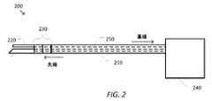
図2は、いくつかの実施形態による低侵襲性手術器具200を示す簡略図である。いくつかの実施形態では、手術器具200は、図1の器具130のいずれかと一致し得る。図2に示され、本明細書で使用される「基端」及び「先端」の方向は、手術器具200の構成要素の相対的な向き及び位置を説明するのに役立つ。先端部は、一般に、器具200を保持するユーザ又は機械、器具200を保持するコンピュータ支援装置(コンピュータ支援装置110等)のベースからの運動学的連鎖にさらに沿った方向の、及び/又は手術器具200の使用を意図した動作における手術作業部位に最も近い要素を指す。基端部は、一般に、コンピュータ支援装置のベース、器具200を保持するユーザ又はマシン、及び/又は器具200を保持するためのコンピュータ支援装置の関節式アームのうちの1つに向かう運動学的連鎖に沿ったより近い方向の要素を指す。 FIG. 2 is a simplified diagram illustrating a minimally invasive
図2に示されるように、手術器具200は、長いシャフト210を含み、この長いシャフト210は、シャフト210の先端部に配置されたエンドエフェクタ220を、シャフト210の基端部において手術器具200を関節式アーム及び/又はコンピュータ支援装置に取り付ける箇所に結合する。手術器具200が使用されている特定の処置に応じて、シャフト210は、エンドエフェクタ220を患者の解剖学的構造内に位置する遠隔手術部位の近傍に配置するために、患者の開口部(例えば、体壁切開部、自然オリフィス等)を介して挿入することができる。図2にさらに示されるように、エンドエフェクタ220は、2つの顎付きグリッパ式エンドエフェクタと略一致しており、いくつかの実施形態では、図3A~図3Dに関して以下でより詳細に説明するように、切断及び/又はステープル留め機構をさらに含むことができる。しかしながら、当業者であれば、ステープル以外の留め具を有するエンドエフェクタ等の、異なるエンドエフェクタ220を有する異なる手術器具200が、可能であり、且つ本明細書の他の箇所に記載されるような手術器具200の実施形態と一致してもよいことを理解するであろう。 As shown in FIG. 2 ,
エンドエフェクタ220を有する手術器具200等の手術器具は、典型的に、その動作中に多自由度(DOFs)を使用する。手術器具200及びその手術器具200が取り付けられる関節式アーム及び/又はコンピュータ支援装置の構成に応じて、エンドエフェクタ220の位置付け、向き合せ、及び/又は動作に使用され得る様々なDOFsが可能である。いくつかの例では、シャフト210は、エンドエフェクタ220が配置される患者の解剖構造内の深さを制御するために使用され得る挿入DOFを提供するために、先端方向に挿入され及び/又は基端方向に後退され得る。いくつかの例では、シャフト210は、エンドエフェクタ220を回転させるために使用され得るロールDOFを提供するために、そのシャフトの長手方向軸の周りに回転することができる。いくつかの例では、シャフト210及び手術器具200の基端側に配置された関節式アーム120の関節及びリンク等の1つ又は複数の関節及び/又はリンクによって、エンドエフェクタ220の位置及び/又は向きの追加の柔軟性を提供することができる。いくつかの例では、オプションの関節式手首230を使用して、エンドエフェクタ220をシャフト210の先端部に結合することができる。いくつかの例では、関節式手首230は、オプションで、1つ又は複数の「ロール」、「ピッチ」、及び「ヨー」DOF(s)をそれぞれ提供し得る1つ又は複数のロール、ピッチ、又はヨー関節等の1つ又は複数の回転関節を含むことができ、この回転関節は、シャフト210の長手方向軸線に対するエンドエフェクタ220の向きを制御するために使用され得る。いくつかの例では、1つ又は複数の回転関節は、ピッチ及びヨー関節;ロール、ピッチ、及びヨー関節;ロール、ピッチ、及びロール関節等を含み得る。いくつかの例では、エンドエフェクタ220は、以下でさらに詳細に説明するように、エンドエフェクタ220の顎部の開閉を制御するために使用されるグリップDOF、及び/又はステープル留め及び切断機構の伸長、後退、及び/又は動作を制御するために使用される活性化DOFをさらに含む。 Surgical instruments such as
手術器具200は、シャフト210の基端部に配置された駆動システム240をさらに含む。駆動システム240は、手術器具200に力及び/又はトルクを導入するための1つ又は複数の構成要素を含み、この構成要素を使用して、手術器具200によってサポートされる様々なDOFsを操縦することができる。いくつかの例では、駆動システム240は、オプションで、図1の制御ユニット140等の制御ユニットから受信した信号に基づいて動作する1つ又は複数のモータ、ソレノイド、サーボ、能動アクチュエータ、油圧、空気圧等を含むことができる。いくつかの例では、信号は、1つ又は複数の電流、電圧、パルス幅変調波形等を含むことができる。いくつかの例では、駆動システム240は、オプションで、手術器具200が取り付けられる関節式アーム120のいずれか等の関節式アームの一部である対応するモータ、ソレノイド、サーボ、能動アクチュエータ、油圧、空気圧等に結合され得る1つ又は複数のシャフト、ギヤ、プーリー、ロッド、バンド等を含むことができる。いくつかの例では、シャフト、ギヤ、プーリー、ロッド、バンド等の1つ又は複数の駆動入力を使用して、モータ、ソレノイド、サーボ、能動アクチュエータ、油圧、空気圧装置からの力及び/又はトルクを受け取り、これらの力及び/又はトルクを適用して、手術器具200の様々なDOFを調整する。この説明では、「力」及び「トルク」の両方が、時には、線形力、回転トルク、及び/又は適用可能であればその両方を示すために個別に使用される。
いくつかの実施形態では、駆動システム240によって生成された及び/又は駆動システム240によって受け取られたトルク及び/又はトルクは、1つ又は複数の駆動機構250を使用して、駆動システム240からシャフト210に沿って、駆動システム240の先端側に配置された手術器具200の様々な関節及び/又は要素に伝達される。いくつかの例では、1つ又は複数の駆動機構250は、オプションで、1つ又は複数のギヤ、レバー、プーリー、ケーブル、ロッド、バンド等を含むことができる。いくつかの例では、シャフト210は中空であり、駆動機構250は、シャフト210の内側に沿って、駆動システム240からエンドエフェクタ220及び/又は関節式手首230の対応するDOFに渡される。いくつかの例では、駆動機構250のそれぞれは、オプションで、ボーデンケーブルのような構成の中空シース又は管腔の内部に配置されたケーブルであってもよい。いくつかの例では、ケーブル及び/又は管腔の内部は、オプションで、ポリテトラフルオロエチレン(PTFE)等の低摩擦コーティングでコーティングしてもよい。いくつかの例では、キャプスタン(capstan)又はシャフトの周りにケーブルを巻き付け及び/又は巻き戻すこと等によって、ケーブルのそれぞれの基端部が駆動システム240内に引き込まれ及び/又は押し込まれると、ケーブルの先端部は、それに応じて移動し、且つエンドエフェクタ220、関節式手首230、及び/又は手術器具200の1つ又は複数のDOFsを調整するための適切な力及び/又はトルクを与える。 In some embodiments, torque and/or torque generated by and/or received by
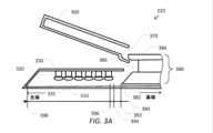
図3A~図3Dは、いくつかの実施形態によるエンドエフェクタ220の簡略図である。図3A~図3Dに示されるように、手術器具200又はエンドエフェクタ220の先端部は、顎の閉鎖、組織のステープル留め、及び組織の切断のための機構を含む。エンドエフェクタ220が1つの固定式顎部及び1つの可動式顎部で図示され説明されているが、当業者には、手術器具200の先端部が2つの可動式顎部を使用するように修正され得ることは理解されよう。以下の説明は、組織を同時に把持し、ステープル留めし、及び切断する把持器、ステープル留め器、及び切断器具の文脈であるが、そのように説明された態様は、切断機構を備えた又は備えていない器具、ステープル留め以外の融着をサポートする器具等に適用可能であり得ることをさらに理解すべきである。 3A-3D are simplified diagrams of an
図3Aは、エンドエフェクタ220の顎部が開いた位置で示されるような、作動前のエンドエフェクタ220の切断側面図を示す。図示されるように、エンドエフェクタは、略固定された第1の顎部310を含む。顎部310は、複数のステープル330及び複数のステープル押込み器(staple pusher)335を保持する交換可能なステープルカートリッジ320を受容するように設計される。ステープルカートリッジ320は、1つ又は複数のステープル330を使用した後で第1のステープルカートリッジ320を取り外し、第1のステープルカートリッジ320を、外科的処置を行うためにさらに使用され得る新しいステープル330のセットを有する第2のステープルカートリッジ320に交換することによって、エンドエフェクタ220が再使用できるように交換可能に設計される。図3Bは、ステープルカートリッジ320の上面図を示す。図3Bに示されるように、ステープルカートリッジは、6列のステープルスロット340を含み、このスロットを介して、エンドエフェクタ220の作動時に把持した組織にステープル330を適用することができる。ステープルスロット340の列は、切断スロット350の両側に3つの列を含み、これについては以下でさらに詳細に説明する。切断スロット350の両側にステープル330を配置することにより、切断ラインの両側の組織を閉じるように、所望の切断ラインの両側にステープル330を適用することが可能になる。ステープルスロット340の列はまた、互いに対してオフセットされて、切断ラインの両側に沿ってより完全な組織閉鎖を提供する。また、ステープルカートリッジ320が、6列のオフセットされたステープルスロット340を有し、各列が均一なサイズの6つのステープルスロット340を有するように示されているが、当業者には、より少ない又は多いステープを含むより少ない又は多い列のステープルスロット、サイズが変化するステープルスロット、様々なパターンのステープルスロットが可能であることが理解されよう。 FIG. 3A shows a cutaway side view of the
図3Aにさらに示されるように、エンドエフェクタ220は、その基端部近くのピボット点(図示せず)の周りを移動可能な第2の顎部360をさらに含む。ステープル器具の文脈では、第2の顎部360は、代替的に、アンビル360と呼ばれ得る。図3Aに示される実施形態では、アンビル360は、エンドエフェクタ220の初期作動時に、組織がアンビル360と顎部310との間で把持されるまで、アンビル360と顎部310との間のギャップが速やかに減少するように構成された移行エッジ370を含む。エンドエフェクタ220の作動は、往復要素380をエンドエフェクタ220の基端部からエンドエフェクタ220の先端部に移動させることによって達成される。往復要素380は、1つ又は複数の駆動機構250の先端部に結合される。 As further shown in FIG. 3A, the
往復要素380は、スレッド(sled)382及びフランジ384を含み、スレッド382とフランジ384との間に結合された切断ブレード386を含む。往復要素380は、図3Dに示されるエンドエフェクタ220の切断端面図に示されるような略I字型ビーム形式の断面形状を有する。ステープル留めのためにエンドエフェクタ220が作動されるときに、スレッド382は、往復要素380が駆動機構250によって押されると、顎部310及びステープルカートリッジ320内に沿って前進される。スレッド382は、くさび形の前縁部又は先端部を含み、それによって前縁部がステープル押込み器335のそれぞれに遭遇すると、前縁部は、対応するステープル330に対してステープル押込み器335を押し当てる。この動作は、ステープルスロット340のそれぞれのスロットを介した各ステープル330の発射を生じさせる。スレッド382がその前縁部において単一の楔形で示されているが、スレッド382は、オプションで、ステープルカートリッジ320内のステープル330及びステープル押込み器335の各列について別個の楔形を含んでもよい。さらに、別個の楔形のそれぞれは、オプションで、スレッド382の動く方向に互いに対して千鳥状に(staggered)され得る。いくつかの実施形態では、ステープル押込み器335はオプションであり、スレッド382の前縁部はステープル330に対して直接的に押し当てられる。スレッド382が顎部310及びステープルカートリッジ320内に沿って前進されると、フランジ384はアンビル360内に沿って前進される。フランジ384の前縁先端部が移行エッジ370に遭遇すると、フランジ384は、アンビル360と顎部310との間のギャップの急速な初期閉鎖を生じさせる。切断ブレード386はスレッド382及びフランジ384の先端部に対して幾分基端側に配置され、それによって任意の把持された組織の切断は、切断線の両側に沿ったステープル330の発射を伴う(trails)。往復要素380が作動されると、切断ブレード386は、切断スロット350だけでなくアンビル360に位置する対応する切断スロット355に沿って移動する。 Reciprocating
図3C及び図3Dは、エンドエフェクタ220が完全に作動した後のエンドエフェクタ220の切断側面図及び切断端面図をそれぞれ示している。図示されるように、往復要素380は、スレッド382、フランジ384、及び切断ブレード386と共に、エンドエフェクタ220の先端部に配置される。スレッド382の前縁部がステープル押込み器335のそれぞれに遭遇すると、スレッド382の前縁部は、ステープル押込み器335を押し、次にステープル330をそれぞれのステープルスロット340を通って押し上げ、ステープルは、任意の把持された組織を貫通してアンビル360の面内に押し込まれ、図3Cに示されるように最終形状に曲げられる。アンビル360と顎部310との間のギャップは、アンビル360内のフランジ384の存在によって維持される。このように、往復要素380、スレッド382、フランジ384、及び切断ブレード386は、エンドエフェクタ220の全ての構成要素であり、これら構成要素は、往復要素380の運動を制御するアクチュエータによって供給される加えられた力又はトルクに応答して移動する。 3C and 3D show cutaway side and cutaway views, respectively, of
エンドエフェクタ220の動作は、作動されるにつれていくつかの実際的な考慮の対象となる。最初に、往復要素380を前進させるために使用される駆動機構250に加えるべき非常に少ない力又はトルクで、往復要素380を高レベルの速度で先端方向に移動させることができる。しかしながら、フランジ384が前縁部370に遭遇し始め、且つアンビル360と顎部310との間のギャップが急速に閉じ始めると、アンビル360と顎部310との間に把持された任意の組織は、往復要素380の更なる移動に対して抵抗し始める。これを補償するために、駆動システム240は、追加の力及び/又はトルクを駆動機構250に加えて、往復要素380の速度を維持する。力及び/又はトルクの監視は、顎部310及び/又はアンビル360の許容できない屈曲及び/又は広がり;エンドエフェクタ220、駆動システム240、及び/又は駆動機構250への損傷;及び/又は把持された組織に対する損傷を回避するために、加えられた力及び/又はトルクに関して妥当な上限が維持されるのを確実にするように行われる。第2に、組織がアンビル360と顎部310との間で把持されるときに、組織は、把持の圧力によって流体が組織から押し出されると、典型的には乾燥し始める。往復要素380の速度が適切に制御されている限り、往復要素380を前進させ続けるための力及び/又はトルクの量は、一般に、順応性(compliant)組織の合理的な制限内で管理することができる。第3に、スレッド382がステープル押込み器335のそれぞれをステープル330に押し当て得るように追加の力及び/又はトルクが典型的に必要とされ、それによって往復要素380の所望の速度を維持しながら、ステープル330を把持した組織を貫通して押し込み、及び/又は切断ブレード386によって把持された組織を切断できる。この追加の力及び/又はトルクは、ステープル留めされる組織の特性が変化したり、以前に適用したステープル線が交差したりする等して、著しく変化する可能性がある。 Operation of the
エンドエフェクタ220の円滑な動作を達成するためには、組織との初期接触、ステープル330の発射、及び把持されたステープル留めされた組織の切断の全体を通して往復要素380を一定速度で作動させることが一般に望ましい。いくつかの実施形態では、これは、顎部310及び/又はアンビル305の許容できない屈曲及び/又は広がり;エンドエフェクタ220、駆動システム240、及び/又は駆動機構250への損傷;及び/又は把持された組織に対する損傷を低減及び/又は回避するように、加えられた力及び/又はトルクを監視及び/又は制限することによって生じる。1つのアプローチは、駆動システム240に関して最大の力及び/又はトルク制限を受ける一定の速度設定点を用いてエンドエフェクタ220を動作させることである。一定の速度設定点は、動作速度と、力及び/又はトルク制限に遭遇するリスクとの間のバランスを提供するように選択され得る。いくつかの例では、一定の速度設定点は、オプションで、把持され、ステープル留めされ、クランプされた組織のタイプに基づいて、オペレータ等によって調整可能であり得る。いくつかの実施形態及び/又は特定の動作条件下では、特定の速度設定点及び/又は速度設定点の範囲は、低過ぎる一定の速度設定点、不調和動作によって、又は往復要素380を恐らくは不規則なパターン等で増減速させる、力及び/又はトルク制限を含む一定程度の遭遇によって、エンドエフェクタ220の最適な動作未満となる場合がある。 To achieve smooth operation of the
駆動システム240及び駆動機構250によって加えられる力及び/又はトルクに基づいて適応する往復要素380の速度プロファイルを使用して、エンドエフェクタ220の改善された動作及びより円滑な動作が可能となる。例えば、力及び/又はトルクが増大し始めると、往復要素380の速度は制御された態様で減少し、力及び/又はトルクが減少し始めると、往復要素380の速度は制御された態様で増大する。こうして、往復要素380の速度を間接的に減速させる単一の力及び/又はトルク制限に頼ることと比較して、エンドエフェクタ220のより滑らかな動作が得られる。例えば、往復要素380が最大力及び/又はトルク制限で減速するにつれて、力及び/又はトルク閾値が最大力及び/又はトルク制限より低いときに減速することは、始動及び停止がより少ない動作とさせることができる。 Improved and smoother motion of the
いくつかの実施形態によれば、速度を調整するために他の技術を使用してもよい。例えば、力及び/又はトルクが閾値量を超えると、往復要素380の速度は、往復要素380の現在検出された速度及び/又は現在検出された速度より僅かに低い速度設定点に設定され得る。 Other techniques may be used to adjust the speed, according to some embodiments. For example, when the force and/or torque exceeds a threshold amount, the speed of reciprocating
再び図3Aを参照すると、例示的なステープル留めプロセスの作動中に往復要素380の移動方向を示す矢印390が示されている。一組の点線392,394,396,398は、スレッド382の先端チップがステープル留め動作中に到達する特定の位置を示す。スレッド382の先端チップが点線392及び394によって示される位置の間に配置されるときに、ステープラは「把持」状態(「把持段階」でもある)にあり、第1の顎部310及び第2の顎部360は、おおよそ平行な姿勢に近づき、且つ患者の組織を軽く把持することができる。スレッド382の先端チップが点線394によって示される位置に到達すると、ステープラは、把持状態から「クランプ状態であるが未発射状態」状態(「クランプ状態であるが未発射段階」でもある)に移行し、第1の顎部310及び第2の顎部360は、患者の組織に実質的なクランプ力を及ぼすために十分に近接して保持される。このクランプ状態であるが未発射状態は、患者の組織のある程度のステープル留め予圧を与えることができ、組織を平坦化してステープル留め動作の成功の可能性を高めるのに役立つ。 Referring again to FIG. 3A,
スレッド382の先端チップが点線396によって示される位置に到達すると、ステープラは、クランプ状態であるが未発射状態から「発射」状態(「発射段階」でもある)に移行し、スレッド382は、ステープル押込み器335の様々な押込み器を対応するステープル330に押し当て、ステープルスロット340を介してこれらのステープル330を発射する。ステープル留めプロセスは、スレッド382の先端チップが点線398によって示される位置のその目標に到達すると終了する。この発射状態は、クランプ状態であるが未発射状態とは別の「クランプ状態」とも呼ばれ得る。 When the leading tip of
いくつかの実施形態によれば、加えられた力又はトルクは、発射状態、クランプ状態であるが未発射状態、把持状態、及び/又はこれらの状態の任意の2つ又は3つの組合せの間に監視され得る。いくつかの例では、加えられた力又はトルクが、本開示で論じられたように、発射状態で監視され、プロセスを実行してもよい。いくつかの例では、加えられた力又はトルクは、本開示で論じられたように、発射状態及びクランプ状態であるが未発射状態の全部又は一部で監視され、プロセスを実行してもよい。いくつかの例では、発射状態及びクランプ状態であるが未発射状態に、異なる力又はトルク制限閾値及び/又は他のパラメータを使用してもよい。 According to some embodiments, the applied force or torque is during a fired state, a clamped but unfired state, a grasped state, and/or a combination of any two or three of these states. can be monitored. In some examples, the applied force or torque may be monitored during launch to effectuate processes as discussed in this disclosure. In some examples, the applied force or torque may be monitored in all or part of the fired and clamped but unfired states to perform processes as discussed in this disclosure. . In some examples, different force or torque limit thresholds and/or other parameters may be used for the fired and clamped but unfired states.
いくつかの実施形態によれば、フィードバックが、ステープル留め動作中に外科医及び/又は他の医療関係者に提供され得る。いくつかの例では、コンピュータ支援システム(例えば、コンピュータ支援システム100)内の制御ユニットは、クランプ状態であるが未発射状態におけるステープル留めプロセスの成功の可能性を推定し、そのような推定値を視覚的表示、聴覚フィードバック等を含む任意の適切な方法によってユーザに提供することができる。いくつかの例では、このフィードバックは、ステープル留めプロセスが容易に逆転され得る間に提供され得、それによりステープルは、消費されず、処置中に他の場所で使用され得る。いくつかの実施形態では、コンピュータ支援システムは、ステープル留め成功の可能性が十分に高いと測定されるまで、発射状態の開始を禁止する。 According to some embodiments, feedback may be provided to the surgeon and/or other medical personnel during the stapling operation. In some examples, a control unit within a computer-aided system (e.g., computer-aided system 100) estimates the likelihood of success of the stapling process in the clamped but unfired state, and uses such estimates as It can be provided to the user in any suitable manner, including visual display, auditory feedback, and the like. In some instances, this feedback may be provided while the stapling process can be easily reversed so that the staples are not consumed and can be used elsewhere during the procedure. In some embodiments, the computer-aided system inhibits initiation of the firing state until the likelihood of successful stapling is determined to be sufficiently high.
いくつかの実施形態では、手術器具200及び/又は関連するコンピュータ支援システム(例えば、コンピュータ支援システム100)は、これらの3つの状態をオペレータに区別させるユーザインターフェイスを用いて構成される。例えば、いくつかの実施形態は、ノブ、ボタン、スイッチ、ペダル、及び他の入力装置の異なる組合せによって状態を変化させるための異なる制御を提供する。いくつかの例では、遠隔操作式コンピュータ支援システムの場合に、このコンピュータ支援システムは、(1)能動ステープラ器具に関連するマスターマニピュレータ入力装置での摘み(pinching)入力を感知することに応答して、スレッド382に点線392に対応する位置に把持速度で移動するよう命令すること等による、把持状態に入るコマンド、(2)第1のペダルの踏込みに応答して、スレッド382に点線394に対応する位置にクランプ状態であるが未発射状態速度で移動するよう命令すること等による、クランプ状態であるが未発射状態に入るコマンド、(3)スレッド382に点線396を通り過ぎて、エンドエフェクタ220の先端部における点線398までの位置に発射速度で移動するよう命令すること等による、発射状態に入り、その発射状態を継続するコマンドを出すように構成することができる。いくつかの実施形態は、時間切れ(timeout)を含むように構成することもでき、それによって関連する所定の期間が摘み動作、第1のペダルの踏込み、及び/又は第2のペダルの踏込みで経過した後に、摘み動作、第1のペダルの踏込み、及び/又は第2のペダルの踏込みが関連する状態のコマンドがもたらされる。いくつかの実施形態では、手術器具200又は関連するコンピュータ支援システム(例えば、コンピュータ支援システム100)は、ユーザ制御の観点から、「把持」状態と「クランプ状態であるが未発射」状態、又は「クランプ状態であるが未発射」状態と「発射」状態を組み合わせるユーザインターフェィスを構成する。いくつかの実施形態では、単一のスイッチ又はペダルが、把持状態に入るよう命令し、クランプ状態であるが未発射状態に移行させるためにオペレータに提供される。いくつかの実施形態では、単一のスイッチ又はペダルが、クランプ状態であるが未発射状態に入るよう命令し、発射状態に移行させるためにオペレータに提供される。 In some embodiments,
図4は、いくつかの実施形態によるエンドエフェクタを動作させるための状態マシン400の簡略図である。状態マシン400の1つ又は複数の状態410-490は、少なくとも部分的に、非一時的で有形の機械可読媒体に記憶された実行可能コードの形態で実装され得、そのコードが1つ又は複数のプロセッサ(例えば、制御ユニット140内のプロセッサ150)によって実行されるときに、1つ又は複数のプロセッサに状態410-490のうちの1つ又は複数を実施させることができる。いくつかの実施形態では、状態マシン400は、制御アプリケーション170等のアプリケーションによって実装してもよい。いくつかの実施形態では、状態マシン400は、アクチュエータによって加えられたトルクに基づいて、往復要素380の動きを制御するアクチュエータ等のアクチュエータの速度設定点を限定及び/又は制限するために使用され得る。いくつかの実施形態では、状態マシン400が動作している間に、アクチュエータのトルクが監視される。いくつかの実施形態では、状態410-490の間の状態移行は、示された状態移行が生じたときに発生してもよく、又はオプションとして、状態マシン400を実装する制御ループの実行に基づいて周期的な間隔で発生してもよい。 FIG. 4 is a simplified diagram of a
状態マシン400は、開始状態410で開始する。1つ又は複数の制御、入力等の起動を介した外科医等のオペレータの方向及び/又はコマンドに応じて、エンドエフェクタの動作が前クランプ状態420に移行する。前クランプ状態420では、往復要素380を前進させるアクチュエータ等のアクチュエータの速度設定点が、初期速度v0に設定される。いくつかの例では、速度v0は、オプションで、アクチュエータの最大許容速度に一致してもよい。いくつかの実施形態では、エンドエフェクタの動作は、アクチュエータが最小距離を移動するか、又は初期位置(例えば、点線394に対応する位置)に到達するまで、前クランプ状態420のままである。いくつかの例では、最小距離は、フランジ384の先端部が移行エッジ370に遭遇し、アンビル360と顎部310との間のギャップが閉鎖し始める少し前及び/又は後等に、組織の初期把持が生じる位置に対応してもよい。いくつかの実施形態では、組織のこの初期把持は、図3Aに関連して説明した「把持」状態及び/又は把持状態の直前に適用可能な把持前状態に関連する。いくつかの実施形態では、組織のこの初期把持は、図3Aに関連して説明した「把持」及び「クランプ状態であるが未発射」状態の一部又は全部に関連する。アクチュエータのトルクが最大トルクτmaxを超えると、最小距離に到達する前に、状態マシン400は、不成功(fail)状態490に移行する。状態マシン400は、不成功状態490を人間のオペレータに視覚的に、聴覚的に、又は他の何らかのフィードバック方法によって示すことができる。アクチュエータのトルクが最大トルクを超えない場合に、状態マシン400は初期クランプ状態430に移行する。
初期クランプ状態430では、アクチュエータの速度設定点は、初期クランプ速度v1に設定される。次に、アクチュエータの制御は、往復要素380がエンドエフェクタ220の先端部に前進されたときやトルク閾値τ1に到達するとき等、目標位置に到達するまで速度v1で継続する。トルクτ1は、最大トルクτmaxよりも低い。いくつかの例では、速度v1は、オプションで、初期速度v0と同じ速度であってもよい。状態マシン400は、成功状態480を人間のオペレータに視覚的に、聴覚的に、及び/又は他の何らかのフィードバック方法によって示すことができる。目標位置に到達すると、状態マシン400は、成功状態480に移行する。目標位置に到達する前にアクチュエータのトルクがトルクτ1を超えると、状態マシン400は、第1の低速クランプ状態440に移行する。In the
第1の低速クランプ状態440では、アクチュエータの速度設定点は、速度v1よりも低い速度v2に設定される。次に、アクチュエータの制御は速度v2で継続する。第1の低速クランプ状態440にある間に、アクチュエータのトルクは、そのトルクが増減少しているかを確認するためにさらに監視される。アクチュエータのトルクが、トルクτ1よりも低いトルクτ2(例えば、τ1よりも5~20%低い、及び/又はτ1よりも低い1~3Nmの範囲)まで減少すると、状態マシン400は、初期クランプ状態430に戻り、そこでアクチュエータの速度設定点を速度v1に再び増大させる。トルクτ2がトルクτ1よりも小さい量は、アクチュエータの速度設定点の過度なスラッシング(thrashing)を避けるために、アクチュエータの速度制御にヒステリシスを導入するように設定してもよい。アクチュエータのトルクがトルクτ3まで増大すると、状態マシン400は第2の低速クランプ状態450に移行する。トルクτ3が最大トルクτmaxよりも低いが、典型的にはトルクτ1よりも高いので、トルクの増大が、アクチュエータについてより低い速度設定点になるように継続される。目標位置に到達すると、状態マシン400は成功状態480に移行する。In the first low speed clamp state 440, the actuator velocity set point is set to velocityv2 , which is lower than velocityv1 . Control of the actuator then continues at speedv2 . While in the first low speed clamping state 440, the actuator torque is further monitored to see if the torque is increasing or decreasing. When the actuator torque decreases to a torque τ2 that is less than the torque τ1 (eg, in the range of 5-20% less than τ1 and/or 1-3 Nm less than τ1 ), the state machine 400: We return to the
第2の低速クランプ状態450では、アクチュエータの速度設定点は速度v2よりも低い速度v3に設定される。次に、アクチュエータの制御は速度v3で継続する。第2の低速クランプ状態450にある間に、アクチュエータのトルクは、そのトルクが増減しているかを確認するためにさらに監視される。アクチュエータのトルクがトルクτ3よりも低いトルクτ4まで減少すると、状態マシン400は第1の低速クランプ状態440に戻り、そこでアクチュエータの速度を増大させる。トルクτ4がトルクτ3よりも小さい量は、アクチュエータの速度設定点の過度なスラッシングを避けるために、アクチュエータの速度制御にヒステリシスを導入するように設定してもよい。アクチュエータのトルクがトルクτ5まで増大すると、状態マシン400は待機状態460に移行する。トルクτ5は、オプションで、最大トルクτmaxと同じか又はそれよりも低いが、典型的にはトルクτ3よりも高いので、トルクの増大が、アクチュエータについてより低い速度設定点になるように継続される。目標位置に到達すると、状態マシン400は成功状態480に移行する。In the second low speed clamp state 450, the actuator velocity set point is set to velocityv3 , which is lower than velocityv2 . Control of the actuator then continues at velocityv3 . While in the second slow clamp state 450, the actuator torque is further monitored to see if it is increasing or decreasing. When the actuator torque decreases to torque τ4 , which is less than torque τ3 , the
待機状態460では、状態マシン400は、所定の期間(「休止期間」とも呼ばれる)に亘って動作を一時停止する。待機状態460で動作を一時停止するために、状態マシン400は、アクチュエータの速度設定点をゼロに設定してアクチュエータの動作を停止させることによってアクチュエータを一時停止することができる。いくつかの例では、アクチュエータの速度設定点をゼロに設定することにより、把持された組織がさらに乾燥し得る追加の時間が可能になる。いくつかの例では、状態マシン400は、ステープラの作動から一時的な休止を提供するために、所定の期間に亘って待機状態に留まる。いくつかの例では、所定の期間は、オプションで、ハードウェア及び/又はソフトウェアタイマを使用して実施してもよい。所定の期間がタイムアウトした後に、状態マシン400は、試行(try)状態470に自動的に移行する。 In
試行状態470では、アクチュエータの移動を試みる。試行が試みられる度に、試行カウンタが増大する。いくつかの例では、試みは、オプションとして、アクチュエータの速度設定点を速度v3又は別の速度値に戻すことを含むことができる。アクチュエータの移動が可能であり、アクチュエータのトルクがトルクτ5よりも低いトルクτ6を下回ったままである場合に、試行カウンタはゼロにリセットされ、状態マシン400は第2の低速クランプ状態450に戻り、そこでアクチュエータの設定点が速度v3に戻るよう増大される。トルクτ6がトルクτ5よりも低い量は、アクチュエータの速度設定点の過度なスラッシングを避けるために、アクチュエータの速度制御にヒステリシスを導入するように設定してもよい。アクチュエータのトルクがトルクτ6を上回ったままである場合に、試行状態460の間に、状態マシン400は、待機状態460に戻り、且つ追加の時間待機する。状態マシン400は、試行期間が経過し、最小試行距離が達成された後、及び/又はその両方の後にのみ、待機状態460に移行することができるように構成してもよい。試行カウンタが最大試行回数を超えると、状態マシン400は不成功状態490に移行する。The
成功状態480では、成功したステープル留め及び切断が検出され、アクチュエータの制御は、オプションで、エンドエフェクタの顎部が把持した組織の対応する解放を伴って開くように、逆転される。図3A~図3Dの例では、アクチュエータを逆転させることは、スレッド382が顎部310及びステープルカートリッジ320から引き出され、フランジ384がアンビル360から引き出され、アンビル360が開いて旋回することが可能になり、切断ブレード386が駐機(garaged)位置等の安全位置に引き戻されるように、往復要素380を基端方向に引っ張ることを含む。いくつかの例では、ステープル留め及び切断動作の成功は、オプションで、音声及び/又は視覚的な警告を使用してオペレータに報告してもよい。 In the
不成功状態490では、アクチュエータが目標位置に到達することができなかったので、ステープル留め及び切断動作の完了の不成功が検出される。図3A~図3Dの例では、これは、往復要素380を顎部310及びアンビル360の先端部に前進させることができない場合に生じる。不成功状態490にある間に、ステープル留め及び切断動作の不成功を示す音声及び/又は視覚的な警告がオペレータに報告される。いくつかの例では、アクチュエータの逆転は、オプションで、状態マシンによって自動的に又はオペレータの明示的なコマンドで試みることができる。 In the
上で論じられ、ここでさらに強調されるように、図4は、単なる例に過ぎず、この図は特許請求の範囲を過度に制限すべきものでない。当業者であれば、多くの変形形態、代替形態、及び改変形態を認識するであろう。いくつかの実施形態では、トルク以外のエンドエフェクタ及びアクチュエータの特性が、代わりに監視され、上述した状態移行をもたらすことができる。いくつかの例では、トルクの代わりにアクチュエータによって加えられる力を監視してもよい。いくつかの実施形態では、初期クランプ状態430及び前クランプ状態420は、オプションで、単一の状態に組み合わせてもよい。いくつかの実施形態では、第2の低速クランプ状態450を除去して、アクチュエータのトルクがトルクτ3よりも高いときに、状態マシン400が第1の低速クランプ状態400から待機状態460に移行するようにしてもよい。いくつかの実施形態では、第1の低速クランプ状態440及び第2の低速クランプ状態450を除去して、アクチュエータのトルクがトルクτ1よりも高いときに、プロセスが初期クランプ状態430から待機状態460に移行する。いくつかの実施形態では、エンドエフェクタの速度-トルクプロファイルにどの位のステップが望ましいかに応じて、第2の低速クランプ状態450と待機状態460との間に、追加の低速クランプ状態をオプションで追加してもよい。As discussed above and further emphasized here, FIG. 4 is merely an example, which should not unduly limit the scope of the claims. Those skilled in the art will recognize many variations, alternatives, and modifications. In some embodiments, end effector and actuator characteristics other than torque may instead be monitored to effect the state transitions described above. In some examples, force applied by the actuator may be monitored instead of torque. In some embodiments, the initial clamped
いくつかの実施形態では、トルク閾値の適用における一時的な過渡現象の影響を低減するために、1つ又は複数の技術をオプションで使用してもよい。いくつかの例では、状態マシン400の状態移行は、加えられたトルクが、所定の期間に亘って対応するトルク閾値を上回ったままか下回ったままであるときに生じる。いくつかの例では、速度設定点を減少させるトルク閾値と、速度設定点を増大させるトルク閾値とについて、所定の期間をオプションで異ならせることができる。いくつかの例では、状態マシン400の状態移行は、加えられたトルクの平均値が対応するトルク閾値を上回るか下回るときに生じる。いくつかの例では、平均は指数関数的な平滑化を用いて計算される。いくつかの例では、加えられたトルクはローパスフィルタ処理される。 In some embodiments, one or more techniques may optionally be used to reduce the effects of temporary transients in torque threshold application. In some examples, a state transition of
図5は、いくつかの実施形態による図3のエンドエフェクタの速度-トルクプロファイル500の簡略図である。図5に示されるように、速度-トルクプロファイル500は、監視されるトルクに基づいて変化する複数の速度設定を含む。いくつかの例では、速度-トルクプロファイル500は、状態マシン400によって実施される速度設定点と一致する。速度-トルクプロファイル500において、エンドエフェクタ220のアクチュエータ等のアクチュエータの速度設定点は、アクチュエータによって加えられたトルクがトルクτ1を超えるまで、速度v1に設定される。トルクτ1を超えると、速度設定点を速度v2は減少される。次に、アクチュエータの速度は、アクチュエータによって加えられたトルクがトルクτ3を超えるまで、速度v2で制御される。トルクτ3を超えると、速度設定点は速度v3に減少される。次に、アクチュエータの速度は、アクチュエータによって加えられたトルクがトルクτ5を超えるまで、速度v3で制御される。トルクτ5を超えると、速度設定点はゼロに減少される。速度-トルクプロファイル500は、さらに、アクチュエータのトルクがトルクτ6、τ4、及びτ2を下回るまで、アクチュエータの速度設定点がそれぞれ速度v3、v2及びv1に戻すよう増大されないように、ヒステリシスを使用して実施される。ここで、トルクτ6、τ4、τ2は、それぞれトルクτ5、τ3、τ2を下回るように設定される。FIG. 5 is a simplified diagram of the speed-
上で論じられ、ここでさらに強調されるように、図5は、単なる例に過ぎず、特許請求の範囲を過度に制限すべきものでない。当業者であれば、多くの変形形態、代替形態、及び改変形態を認識するであろう。いくつかの実施形態では、トルク以外のエンドエフェクタ及びアクチュエータの特性を速度プロファイルに使用することができる。いくつかの例では、トルクの代わりにアクチュエータによって加えられる力を使用してもよい。いくつかの実施形態では、必要に応じて、3つより少ない及び/又は多いステップを、速度-トルクプロファイルに使用してもよい。いくつかの実施形態では、速度-トルクプロファイル500は、オプションで、τ2をτ1に等しく設定し、τ4をτ3に等しく設定し、且つτ6をτ5に等しく設定することによって、ヒステリシスを使用せずに実施することができる。いくつかの実施形態では、図5のステッププロファイルの代わりに、ヒステリシスを含む又は含まない滑らかな速度-トルクプロファイルをオプションで使用してもよい。いくつかの例では、速度-トルクプロファイルは、オプションで、線形であってもよく、一連のs字形状の滑らかなステップ、及び/又は速度設定点がトルクの関数として計算される他の単調なプロファイルを含むことができる。いくつかの実施形態では、速度設定点を決定するために使用されるトルクは、オプションとして、平均トルク、ローパスフィルタ処理されたトルク等であってもよい。As discussed above and further emphasized here, FIG. 5 is merely an example, which should not unduly limit the scope of the claims. Those skilled in the art will recognize many variations, alternatives, and modifications. In some embodiments, end effector and actuator characteristics other than torque can be used in the velocity profile. In some examples, the force exerted by the actuator may be used instead of torque. In some embodiments, less and/or more than three steps may be used in the speed-torque profile as desired. In some embodiments, the speed-
図6は、いくつかの実施形態によるステープル留め及び切断動作を行うための方法600の簡略図である。方法600のプロセス605~650のうちの1つ又は複数は、少なくとも部分的に、非一時的で有形の機械可読媒体に記憶された実行可能コードの形態で実装してもよい。この実行可能コードは、1つ又は複数のプロセッサ(例えば、制御ユニット140のプロセッサ150)によって実行されると、1つ又は複数のプロセッサにプロセス605~650のうちの1つ又は複数を実行させることができる。いくつかの実施形態では、方法600は、制御アプリケーション170等のアプリケーションによって実行することができる。いくつかの実施形態では、方法600を使用して、アクチュエータによって加えられたトルクに基づいて、往復要素380等の往復要素を作動させるために使用されるアクチュエータの速度を制限することができる。いくつかの実施形態では、方法600のステープル留め及び切断動作は、状態マシン400及び/又は速度トルクプロファイル500に従って実行され得る。いくつかの実施形態では、プロセス615,620、及び630の試験は、同時に及び/又は任意の順序で起こり得る。 FIG. 6 is a simplified diagram of a
プロセス605において、エンドエフェクタが作動される(「発射」もされる)。エンドエフェクタ220等のエンドエフェクタは、駆動システム240内のアクチュエータ等のアクチュエータに、エンドエフェクタの少なくとも1つのDOFを制御するために使用されるトルクを加えることによって発射される。いくつかの例では、アクチュエータは、電流、電圧、パルス幅変調信号等の1つ又は複数の信号をアクチュエータに送ることによって制御される。エンドエフェクタの発射の実際の効果は、エンドエフェクタの設計、使用、目的によって左右される。いくつかの例では、エンドエフェクタの発射は、前クランプ状態420の間に、速度設定点を速度v0に設定する等、アクチュエータの速度設定点を設定することによって開始する。図2及び図3A~図3Dの例を使用すると、アクチュエータは、往復要素380をエンドエフェクタ220の先端部に向かって移動させる力を駆動機構250に加える。これにより、組織を把持するようにアンビル360と顎部310との間のギャップが減少し、ステープル330は、ステープル押込み器335に作用するスレッド382によって把持した組織を貫通して押し込まれ、切断ブレード386は、把持した組織を切断する。エンドエフェクタの発射は、発射の成功又は不成功が決定されるか、及び/又はオペレータによって中断されるまで続く。In
プロセス610において、加えられたトルクが監視される。1つ又は複数のセンサ及び/又は制御アルゴリズムを使用して、アクチュエータによって加えられたトルクが、エンドエフェクタが発射されるときに監視される。例えば、アクチュエータがモータである場合に、モータに印加される電流を監視してこれを使用し、モータによって印加されているトルクを決定することができる。 In
プロセス615において、エンドエフェクタが目標位置にあるかどうかが判定される。1つ又は複数のセンサを使用して、アクチュエータの位置及び/又はエンドエフェクタ上の検出可能な場所の位置が監視される。いくつかの例では、センサは、アクチュエータの駆動シャフトの回転角度を測定することができる。いくつかの例では、1つ又は複数のセンサは、シャフトエンコーダ、ホール効果センサ等を含むことができる。図3A~図3Dの例では、目標位置は、往復要素380のエンドエフェクタ220の先端部への移動に対応し、ステープル330の全てが把持した組織を貫通して発射され、切断ブレード386は、把持した組織を切断する。目標位置に到達すると、エンドエフェクタの動作は成功したとみなされ、速度設定点はゼロに設定される。いくつかの例では、システムのオペレータは、音声及び/又は視覚的な警報によって通知も受ける。いくつかの例では、成功は成功状態480に一致する。目標位置にまだ到達していない場合に、監視されたトルクは、プロセス620で開始する1つ又は複数のトルク閾値と比較される。 In
プロセス620において、加えられたトルクが第1のトルク閾値を上回るかどうかが判定される。プロセス610の間に監視された、加えられたトルクを第1のトルク閾値と比較して、アクチュエータが所望されるよりも多くのトルクをエンドエフェクタに加えているかどうかを判定する。いくつかの例では、第1のトルク閾値は、オプションで、現在の速度設定点に応じて変化する。図4及び図5の例では、第1のトルク閾値は、トルクτ1、τ3、及び/又はτ5の1つ又は複数に対応する。加えられたトルクが第1のトルク閾値を上回ると、プロセス625を使用して速度設定点が減少される。加えられたトルクが第1の閾値を上回っていない場合に、プロセス630を使用してトルクが第2のトルク閾値と比較される。In
プロセス625において、速度設定点が減少される。加えられたトルクが第1の閾値を上回ると、アクチュエータの速度設定点は、把持した組織がさらに乾燥し、1つ又は複数のステープルの発射を遅らせる等の追加の時間を可能にするように減少される。いくつかの例では、速度設定点は、速度-トルクプロファイル等に応じて固定量、パーセンテージ量等に減少させてもよい。図4及び図5の例では、速度設定点は、プロセス620中に使用された以前の速度設定点及び/又は第1のトルク閾値に応じて、速度設定点がv2、v3、又はゼロに減少される。いくつかの例では、速度設定点の減少は、初期クランプ状態430から第1の低速クランプ状態440へ、第1の低速クランプ状態440から第2の低速クランプ状態450へ、及び/又は第2の低速クランプ状態450から待機状態460への状態移行に一致する。速度設定点を減少させた後に、プロセス640を使用してその速度設定点がゼロに減少されるかどうかを判定するために試験される。In
プロセス630において、加えられたトルクが第2の閾値を下回るかどうかが判定される。プロセス610中に監視された、加えられたトルクを第2のトルク閾値と比較して、アクチュエータを増速させることができるかどうかが判定される。いくつかの例では、第2のトルク閾値は、速度設定点にヒステリシスを提供するために、第1のトルク閾値よりも低く設定される。いくつかの例では、第2のトルク閾値は、オプションで、現在の速度設定点に応じて変化する。図4及び図5の例では、第2のトルク閾値は、トルクτ2、τ4及び/又はτ6のうちの1つ又は複数に対応する。加えられたトルクが第2のトルク閾値を下回っている場合に、プロセス635を使用して速度設定点が増大される。加えられたトルクが第2の閾値を下回っていない場合に、プロセス610を使用してトルクが再び監視される。In
プロセス635において、速度設定点が増大する。加えられたトルクが第2の閾値を下回ると、アクチュエータの速度設定点が増大して、エンドエフェクタのより速い動作が可能になる。いくつかの例では、速度設定点は、速度-トルクプロファイルに応じて固定量(例えば、0.1~2ミリメートル(mm)/秒)、パーセンテージ量(例えば、5~25%)等に増大され得る。いくつかの例では、速度が最大設定点にあるとき、速度設定点はプロセス635中にさらに増大しない。図4及び図5の例では、速度設定点は、以前の速度設定値及び/又はプロセス630中に使用される第2のトルク閾値に応じて、v1、v2、又はv3に増大される。いくつかの例では、速度設定点の増大は、試行状態470から第2の低速クランプ状態450へ、第2の低速クランプ状態450から第1の低速クランプ状態440へ、及び/又は第1の低速クランプ状態440から初期クランプ状態430への状態移行に一致する。速度設定点が増大した後に、プロセス610を使用してトルクが再び監視される。In
プロセス640において、速度設定点がゼロであるかどうかが判定される。速度設定点がゼロに到達すると、プロセス645を使用して遅延が導入される。速度設定点がまだゼロでない場合に、プロセス610を使用してトルクが再び監視される。 In
プロセス645において、待機(「一時停止」も)が発生する。速度設定点がゼロに到達すると、エンドエフェクタの発射が所定の期間(例えば、1~10秒)に亘って遅延される。いくつかの例では、所定の期間は、ハードウェア及び/又はソフトウェアタイマを使用して追跡される。図4の例では、プロセス645は待機状態460に対応する。遅延時間が経過した後に、エンドエフェクタの動作がプロセス650を用いてテストされる。 In
プロセス650において、エンドエフェクタの動作が継続できるかどうかが判定される。速度設定点は、プロセス625が最後に実行される前に、速度設定点の値等の非ゼロ値に設定され、アクチュエータによって加えられるトルクが監視される。図4の例では、プロセス650は試行状態470に対応する。アクチュエータによって加えられたトルクが、プロセス620が最後に実行されたときに使用された第1のトルク閾値等の最大トルク閾値を上回り続けている場合に、エンドエフェクタの発射は不成功であるとみなされ、速度設定点はゼロに設定される。いくつかの例では、オプションで、エンドエフェクタの発射を逆転してもよく、及び/又はオプションで、1つ又は複数の音声及び/又は視覚的な警告をオペレータに提供してもよい。過剰に加えられたトルクを検出することなく非ゼロ速度設定点での動きが生じると、速度設定点は保持され、トルクの監視が処理610に続く。 In
上で論じられ、ここでさらに強調されるように、図6は、単なる例に過ぎず、特許請求の範囲を過度に制限すべきものではない。当業者であれば、多くの変形形態、代替形態、及び改変形態を認識するであろう。いくつかの実施形態では、トルク以外のエンドエフェクタ及びアクチュエータの特性は、プロセス610中に監視され、プロセス620及び630中にテストされ得る。いくつかの実施形態では、プロセス645の待機及び/又はプロセス650のテストは、不成功と結論付けられる前に、1回、2回、又はそれ以上繰り返され得る。こうして、方法600は、アクチュエータを複数回休止させ、所定数のアクチュエータ休止が生じた後に不成功を示すことができる。いくつかの例では、ハードウェア又はソフトウェアカウンタを使用して繰返し回数を追跡することができる。 As discussed above and further emphasized here, FIG. 6 is merely an example, which should not unduly limit the scope of the claims. Those skilled in the art will recognize many variations, alternatives, and modifications. In some embodiments, end effector and actuator characteristics other than torque may be monitored during
いくつかの実施形態では、トルク閾値の適用における一時的な過渡現象の影響を低減するために、1つ又は複数の技術をオプションで使用してもよい。いくつかの例では、プロセス620及び630における第1及び第2のトルク閾値に対する加えられたトルクの比較によって、加えられたトルクが所定の期間に亘って第1及び第2のトルク閾値を上回ったままか下回ったままであるかが判定される。いくつかの例では、所定の期間は、オプションで、第1及び第2のトルク閾値について異なっていてもよい。いくつかの例では、プロセス610における加えられたトルクの監視は、加えられたトルクの平均化を含む。いくつかの例では、平均化には指数関数的な平滑化が含まれる。いくつかの例では、プロセス610における加えられたトルクの監視は、加えられたトルクをローパスフィルタ処理することを含む。 In some embodiments, one or more techniques may optionally be used to reduce the effects of temporary transients in torque threshold application. In some examples, the comparison of the applied torque to the first and second torque thresholds in
制御ユニット140等の制御ユニットのいくつかの例は、実行可能コードを含む非一時的な有形の機械可読媒体を含むことができ、実行可能コードが1つ又は複数のプロセッサ(例えば、プロセッサ150)によって実行されると、1つ又は複数のプロセッサに、状態マシン400の状態を実現させ、速度-トルクプロファイル500を実施させ、及び/又は方法600のプロセスを実行させることができる。状態マシン400の実装、速度-トルクプロファイル500、及び/又は方法600のプロセスを含み得る機械可読媒体のいつくかの一般的な形態は、例えば、フロッピー(登録商標)ディスク、フレキシブルディスク、ハードディスク、磁気テープ、他の任意の磁気媒体、CD-ROM、他の光媒体、パンチカード、紙テープ、ホールパターンを含む任意の他の物理的媒体、RAM、PROM、EPROM、FLASH-EPROM、任意の他のメモリチップ又はカートリッジ、及び/又はプロセッサ又はコンピュータが読み取るように適合された任意の他の媒体等である。 Some examples of control units, such as control unit 140, may include a non-transitory tangible machine-readable medium containing executable code, which may be executed by one or more processors (eg, processor 150). may cause one or more processors to implement the states of
例示的な実施形態について図示し説明しているが、広範な修正、変更、及び置換が前述した開示において企図されており、場合によっては、実施形態のいくつかの特徴は、他の特徴の対応する使用なしに用いることができる。当業者であれば、多くの変形形態、代替形態、及び改変形態を認識するであろう。従って、本発明の範囲は、添付の特許請求の範囲によってのみ限定されるべきであり、特許請求の範囲が広く解釈され、本明細書に開示された実施形態の範囲と一致するように解釈されることが妥当である。 Although exemplary embodiments have been illustrated and described, a wide variety of modifications, changes, and permutations are contemplated in the foregoing disclosure, and in some cases some features of the embodiments will have corresponding features in other features. can be used without the use of Those skilled in the art will recognize many variations, alternatives, and modifications. Accordingly, the scope of the invention is to be limited only by the scope of the appended claims, which are to be construed broadly and consistent with the scope of the embodiments disclosed herein. It is reasonable to
以下に、出願当初の特許請求の範囲の内容を実施例として記載しておく。
[実施例1]
コンピュータ支援医療装置と共に使用するための手術器具であって、当該器具は、
当該器具の先端部に配置されたエンドエフェクタと、
アクチュエータと、
該アクチュエータから前記エンドエフェクタに力又はトルクを結合するための1つ又は複数の駆動機構と、を有しており、
当該器具を用いた動作を行うために、前記コンピュータ支援医療装置は、
前記アクチュエータの速度設定点を初期速度に設定し、
前記アクチュエータによって加えられた力又はトルクを監視し、
該加えられた力又はトルクが第1の閾値を上回るときに、前記速度設定点を減少させ、
前記加えられた力又はトルクが第2の閾値を下回るときに、前記速度設定点を増大させ、
前記加えられた力又はトルクが最大閾値を上回るときに、前記速度設定点をゼロに減少させ、
前記速度設定点に基づいて前記アクチュエータを駆動させる、ように構成され、
前記第1及び第2の閾値は前記最大閾値よりも低い、
器具。
[実施例2]
前記動作は、把持、ステープル留め、及び切断のうちの1つ又は複数を含む、実施例1に記載の器具。
[実施例3]
前記第2の閾値は前記第1の閾値よりも低い、実施例1に記載の器具。
[実施例4]
前記第2の閾値は前記第1の閾値に等しい、実施例1に記載の器具。
[実施例5]
前記速度設定点は、速度プロファイルに従って増減される、実施例1に記載の器具。
[実施例6]
前記速度プロファイルは単調である、実施例5に記載の器具。
[実施例7]
前記速度設定点は、前記加えられた力又はトルクに基づいて計算された速度値まで増減される、実施例1に記載の器具。
[実施例8]
前記第1及び第2の閾値は、前記加えられた力又はトルクに基づいて変化する、実施例1に記載の器具。
[実施例9]
前記加えられた力又はトルクが前記最大閾値を上回るときに、前記コンピュータ支援医療装置は、前記動作を続行する前に、所定の期間に亘って待機するようにさらに構成される、実施例1に記載の器具。
[実施例10]
前記待機後に、前記コンピュータ支援医療装置は、
前記速度設定点を非ゼロ値に設定し、
前記加えられた力又はトルクが引き続き前記最大閾値を上回るかどうかを判定し、
前記加えられた力又はトルクが引き続き前記最大閾値を上回るときに、不成功を示す、ようにさらに構成される、実施例9に記載の器具。
[実施例11]
前記待機後に、前記コンピュータ支援医療装置は、
前記速度設定点を非ゼロ値に設定し、
前記加えられた力又はトルクが引き続き前記最大閾値を上回るかどうかを判定し、
前記速度設定点をゼロに戻すよう設定し、前記加えられた力又はトルクが引き続き前記最大閾値を上回る場合に再び待機し、
前記加えられた力又はトルクが引き続き前記最大閾値を上回るときに所定数の待機サイクル後に不成功を示す、ようにさらに構成される、実施例9に記載の器具。
[実施例12]
前記コンピュータ支援医療装置は、目標位置に到達したときに成功を示すようにさらに構成される、実施例1に記載の器具。
[実施例13]
前記速度設定点は、前記加えられた力又はトルクが所定の期間に亘って前記第1の閾値を上回ったままであるとき、減少される、実施例1に記載の器具。
[実施例14]
前記速度設定点は、前記加えられた力又はトルクが所定の期間に亘って前記第2の閾値を下回ったままであるとき、増大される、実施例1に記載の器具。
[実施例15]
前記加えられた力又はトルクを監視するために、前記コンピュータ支援医療装置は、前記加えられた力又はトルクを平均化するようにさらに構成される、実施例1に記載の器具。
[実施例16]
前記加えられた力又はトルクを平均化するために、前記コンピュータ支援医療装置は、前記加えられた力又はトルクを指数関数的に平滑化するようにさらに構成される、実施例15に記載の器具。
[実施例17]
前記加えられた力又はトルクを監視するために、前記コンピュータ支援医療装置は、前記加えられた力又はトルクをローパスフィルタ処理するようにさらに構成される、実施例1に記載の器具。
[実施例18]
コンピュータ支援医療装置と共に使用するための手術器具であって、当該器具は、
当該器具の先端部に配置されたエンドエフェクタと、
アクチュエータと、
該アクチュエータから前記エンドエフェクタに力又はトルクを結合するための1つ又は複数の駆動機構と、を有しており、
当該器具を用いて動作を行うために、前記コンピュータ支援医療装置は、速度設定点に従って前記アクチュエータを駆動することによる状態マシンに従って前記エンドエフェクタを動作させるように構成され、
前記状態マシンは、第1のクランプ状態、第2のクランプ状態、及び待機状態を含み、
前記第1のクランプ状態では、前記アクチュエータの速度設定点は第1の速度に設定され、
前記第2のクランプ状態では、前記アクチュエータの前記速度設定点は、第1の速度よりも低い第2の速度に設定され、
前記待機状態では、前記速度設定点はゼロに設定され、
前記状態マシンは、前記アクチュエータによって加えられた力又はトルクが第1の閾値を上回るときに、前記第1のクランプ状態から前記第2のクランプ状態に移行し、
前記状態マシンは、前記アクチュエータによって加えられた力又はトルクが前記第1の閾値よりも高い最大閾値を上回るときに、前記第2のクランプ状態から前記待機状態に移行し、
前記状態マシンは、前記アクチュエータによって加えられた力又はトルクが第2の閾値を下回るときに、前記第2のクランプ状態から前記第1のクランプ状態に移行する、
器具。
[実施例19]
前記動作は、把持、ステープル留め、及び切断のうちの1つ又は複数を含む、実施例18に記載の器具。
[実施例20]
前記第2の閾値は前記第1の閾値よりも低い、実施例18に記載の器具。
[実施例21]
前記第2の閾値は前記第1の閾値に等しい、実施例18に記載の器具。
[実施例22]
前記第1の速度及び前記第2の速度は、速度プロファイルに従って決定される、実施例18に記載の器具。
[実施例23]
前記速度プロファイルは単調である、実施例22に記載の器具。
[実施例24]
前記第1の速度及び前記第2の速度は、前記加えられた力又はトルクに基づいて決定される、実施例18に記載の器具。
[実施例25]
前記第1及び第2の閾値は、前記加えられた力又はトルクに基づいて変化する、実施例18に記載の器具。
[実施例26]
前記コンピュータ支援医療装置は、目標位置に到達したときに成功を示すようにさらに構成される、実施例18に記載の器具。
[実施例27]
コンピュータ支援医療装置と共に使用するための手術器具の作動方法であって、当該作動方法は、
1つ又は複数のプロセッサが、アクチュエータの速度設定点を初期速度に設定するステップと、
前記1つ又は複数のプロセッサが、前記アクチュエータによって加えられた力又はトルクを測定するステップと、
前記加えられた力又はトルクが第1の閾値を上回るときに、前記1つ又は複数のプロセッサが、前記速度設定点を減少させるステップと、
前記加えられた力又はトルクが第2の閾値を下回るときに、前記1つ又は複数のプロセッサが、前記速度設定点を増大させるステップと、
前記加えられた力又はトルクが最大閾値を上回るときに、前記1つ又は複数のプロセッサが、前記速度設定点をゼロに減少させるステップと、
前記1つ又は複数のプロセッサが、前記アクチュエータを用いて前記手術器具のエンドエフェクタの1つ又は複数の自由度を駆動させるステップと、を含み、
前記第1及び第2の閾値は前記最大閾値よりも低い、
作動方法。
[実施例28]
前記アクチュエータを用いて、把持、ステープル留め、及び切断のうちの1つ又は複数を実行するステップをさらに含む、実施例27に記載の作動方法。
[実施例29]
前記第2の閾値は前記第1の閾値よりも低い、実施例27に記載の作動方法。
[実施例30]
前記第2の閾値は前記第1の閾値に等しい、実施例27に記載の作動方法。
[実施例31]
前記速度設定点は、速度プロファイルに従って増減される、実施例27に記載の作動方法。
[実施例32]
前記速度プロファイルは単調である、実施例31に記載の作動方法。
[実施例33]
前記速度設定点は、前記加えられた力又はトルクに基づいて計算された速度値まで増減少される、実施例27に記載の作動方法。
[実施例34]
前記第1及び第2の閾値は、前記加えられた力又はトルクに基づいて変化する、実施例27に記載の作動方法。
[実施例35]
目標位置に到達したときに成功を示すステップをさらに含む、実施例27に記載の作動方法。
[実施例36]
複数の機械可読命令を含む非一時的な機械可読媒体であって、前記命令がコンピュータ支援医療装置に関連する1つ又は複数のプロセッサによって実行されると、前記1つ又は複数のプロセッサに、
アクチュエータの速度設定点を初期速度に設定させ、
前記アクチュエータによって加えられた力又はトルクを測定させ、
前記加えられた力又はトルクが第1の閾値を上回るときに、前記速度設定点を減少させ、
前記加えられた力又はトルクが第2の閾値を下回るときに、前記速度設定点を増大させ、
前記加えられた力又はトルクが最大閾値を上回るときに、前記速度設定点をゼロに減少させ、
前記アクチュエータを用いて手術器具のエンドエフェクタの1つ又は複数の自由度を駆動させることを含む段階を実行させるように適合され、
前記第1及び第2の閾値は前記最大閾値よりも低い、
機械可読媒体。
[実施例37]
前記段階は、前記アクチュエータを用いて、把持、ステープル留め、及び切断のうちの1つ又は複数を実行させることをさらに含む、実施例36に記載の機械可読媒体。
[実施例38]
前記第2の閾値は前記第1の閾値よりも低い、実施例36に記載の機械可読媒体。
[実施例39]
前記第2の閾値は前記第1の閾値に等しい、実施例36に記載の機械可読媒体。
[実施例40]
前記速度設定点は、速度プロファイルに従って増減される、実施例36に記載の機械可読媒体。
[実施例41]
前記速度プロファイルは単調である、実施例40に記載の機械可読媒体。
[実施例42]
前記速度設定点は、前記加えられた力又はトルクに基づいて計算された速度値まで増減される、実施例36に記載の機械可読媒体。
[実施例43]
前記第1及び第2の閾値は、前記加えられた力又はトルクに基づいて変化する、実施例36に記載の機械可読媒体。
[実施例44]
前記段階は、目標位置に達したときに成功を示させることをさらに含む、実施例36に記載の機械可読媒体。
The contents of the claims as originally filed are described below as examples.
[Example 1]
A surgical instrument for use with a computer-assisted medical device, the instrument comprising:
an end effector disposed at the distal end of the instrument;
an actuator;
one or more drive mechanisms for coupling force or torque from the actuator to the end effector;
To perform operations with the instrument, the computer-assisted medical device comprises:
setting the speed setpoint of the actuator to an initial speed;
monitoring the force or torque applied by the actuator;
decreasing the speed set point when the applied force or torque exceeds a first threshold;
increasing the speed set point when the applied force or torque is below a second threshold;
reducing the speed set point to zero when the applied force or torque exceeds a maximum threshold;
driving the actuator based on the speed setpoint;
the first and second thresholds are lower than the maximum threshold;
instrument.
[Example 2]
2. The instrument of example 1, wherein the actions include one or more of grasping, stapling, and cutting.
[Example 3]
2. The instrument of example 1, wherein the second threshold is lower than the first threshold.
[Example 4]
2. The instrument of example 1, wherein the second threshold is equal to the first threshold.
[Example 5]
2. The instrument of example 1, wherein the speed setpoint is increased or decreased according to a speed profile.
[Example 6]
6. The instrument of example 5, wherein the velocity profile is monotonic.
[Example 7]
2. The instrument of example 1, wherein the speed set point is scaled to a calculated speed value based on the applied force or torque.
[Example 8]
2. The instrument of example 1, wherein the first and second threshold values vary based on the applied force or torque.
[Example 9]
2. According to embodiment 1, wherein when the applied force or torque exceeds the maximum threshold, the computer-assisted medical device is further configured to wait for a predetermined period of time before continuing with the operation. Equipment as described.
[Example 10]
After the waiting, the computer-assisted medical device comprises:
setting the speed setpoint to a non-zero value;
determining whether the applied force or torque continues to exceed the maximum threshold;
10. The instrument of example 9, further configured to indicate failure when the applied force or torque continues to exceed the maximum threshold.
[Example 11]
After the waiting, the computer-assisted medical device comprises:
setting the speed setpoint to a non-zero value;
determining whether the applied force or torque continues to exceed the maximum threshold;
setting the speed set point back to zero and waiting again if the applied force or torque continues to exceed the maximum threshold;
10. The instrument of example 9, further configured to indicate failure after a predetermined number of waiting cycles when the applied force or torque continues to exceed the maximum threshold.
[Example 12]
2. The instrument of example 1, wherein the computer-assisted medical device is further configured to indicate success when reaching the target location.
[Example 13]
2. The instrument of example 1, wherein the speed set point is decreased when the applied force or torque remains above the first threshold for a predetermined period of time.
[Example 14]
2. The instrument of example 1, wherein the speed set point is increased when the applied force or torque remains below the second threshold for a predetermined period of time.
[Example 15]
2. The instrument of example 1, wherein to monitor the applied force or torque, the computer-aided medical device is further configured to average the applied force or torque.
[Example 16]
16. The apparatus of example 15, wherein the computer-assisted medical device is further configured to exponentially smooth the applied force or torque to average the applied force or torque. .
[Example 17]
2. The instrument of example 1, wherein to monitor the applied force or torque, the computer-aided medical device is further configured to low-pass filter the applied force or torque.
[Example 18]
A surgical instrument for use with a computer-assisted medical device, the instrument comprising:
an end effector disposed at the distal end of the instrument;
an actuator;
one or more drive mechanisms for coupling force or torque from the actuator to the end effector;
To operate with the instrument, the computer-aided medical device is configured to operate the end effector according to a state machine by driving the actuator according to a velocity setpoint;
the state machine includes a first clamp state, a second clamp state, and a wait state;
in the first clamped state, the actuator speed set point is set to a first speed;
in the second clamped state, the speed set point of the actuator is set to a second speed that is less than the first speed;
in the standby state, the speed setpoint is set to zero;
the state machine transitions from the first clamped state to the second clamped state when a force or torque applied by the actuator exceeds a first threshold;
the state machine transitions from the second clamped state to the standby state when the force or torque applied by the actuator exceeds a maximum threshold greater than the first threshold;
the state machine transitions from the second clamped state to the first clamped state when the force or torque applied by the actuator is below a second threshold;
instrument.
[Example 19]
19. The instrument of example 18, wherein the actions include one or more of grasping, stapling, and cutting.
[Example 20]
19. The device of example 18, wherein the second threshold is lower than the first threshold.
[Example 21]
19. The instrument of example 18, wherein the second threshold is equal to the first threshold.
[Example 22]
19. The instrument of example 18, wherein the first speed and the second speed are determined according to a speed profile.
[Example 23]
23. The instrument of example 22, wherein the velocity profile is monotonic.
[Example 24]
19. The instrument of example 18, wherein the first speed and the second speed are determined based on the applied force or torque.
[Example 25]
19. The instrument of example 18, wherein the first and second threshold values vary based on the applied force or torque.
[Example 26]
19. The instrument of example 18, wherein the computer-assisted medical device is further configured to indicate success upon reaching the target location.
[Example 27]
A method of operating a surgical instrument for use with a computer-assisted medical device, the method comprising:
one or more processors setting an actuator velocity set point to an initial velocity;
the one or more processors measuring the force or torque applied by the actuator;
said one or more processors decreasing said speed set point when said applied force or torque exceeds a first threshold;
said one or more processors increasing said speed set point when said applied force or torque is below a second threshold;
the one or more processors reducing the speed set point to zero when the applied force or torque exceeds a maximum threshold;
the one or more processors using the actuator to drive one or more degrees of freedom of an end effector of the surgical instrument;
the first and second thresholds are lower than the maximum threshold;
How it works.
[Example 28]
28. The method of actuation of example 27, further comprising using the actuator to perform one or more of grasping, stapling, and cutting.
[Example 29]
28. The method of operation of example 27, wherein the second threshold is lower than the first threshold.
[Example 30]
28. The method of operation of embodiment 27, wherein the second threshold is equal to the first threshold.
[Example 31]
28. The method of operation of example 27, wherein the speed set point is increased or decreased according to a speed profile.
[Example 32]
32. The method of operation of example 31, wherein the velocity profile is monotonic.
[Example 33]
28. The method of operation of embodiment 27, wherein the speed set point is increased or decreased to a calculated speed value based on the applied force or torque.
[Example 34]
28. The method of operating example 27, wherein the first and second threshold values vary based on the applied force or torque.
[Example 35]
28. A method of operation as in example 27, further comprising indicating success when the target location is reached.
[Example 36]
A non-transitory machine-readable medium containing a plurality of machine-readable instructions which, when executed by one or more processors associated with a computer-assisted medical device, causes the one or more processors to:
Let the actuator speed setpoint be set to the initial speed,
causing the force or torque applied by the actuator to be measured;
decreasing the speed set point when the applied force or torque exceeds a first threshold;
increasing the speed set point when the applied force or torque is below a second threshold;
reducing the speed set point to zero when the applied force or torque exceeds a maximum threshold;
adapted to perform steps including actuating one or more degrees of freedom of an end effector of a surgical instrument with the actuator;
the first and second thresholds are lower than the maximum threshold;
machine-readable medium.
[Example 37]
37. The machine-readable medium of example 36, wherein the steps further comprise using the actuator to perform one or more of grasping, stapling, and cutting.
[Example 38]
37. The machine-readable medium of example 36, wherein the second threshold is lower than the first threshold.
[Example 39]
37. The machine-readable medium of example 36, wherein the second threshold is equal to the first threshold.
[Example 40]
37. The machine-readable medium of example 36, wherein the speed setpoint is increased or decreased according to a speed profile.
[Example 41]
41. The machine-readable medium of example 40, wherein the velocity profile is monotonic.
[Example 42]
37. The machine -readable medium of example 36, wherein the speed set point is increased or decreased to a calculated speed value based on the applied force or torque.
[Example 43]
37. The machine -readable medium of example 36, wherein the first and second thresholds vary based on the applied force or torque.
[Example 44]
37. The machine -readable medium of example 36, wherein the steps further comprise indicating success when reaching the target location.
Claims (15)
Translated fromJapaneseエンドエフェクタを有する器具であって、該器具の先端部には前記エンドエフェクタが配置される、器具と、
アクチュエータと、
該アクチュエータから前記エンドエフェクタに力又はトルクを結合するための1つ又は複数の駆動機構と、
1つ又は複数のプロセッサと、を有しており、
前記器具を用いた動作を行うために、前記1つ又は複数のプロセッサは、状態マシンに従って前記エンドエフェクタを動作させるように構成され、
前記状態マシンは、第1のクランプ状態、第2のクランプ状態を含み、
前記第1のクランプ状態では、前記アクチュエータの速度設定点は第1の速度に設定され、
前記第2のクランプ状態では、前記アクチュエータの前記速度設定点は、前記第1の速度よりも低い第2の速度に設定され、
前記状態マシンは、前記アクチュエータによって加えられた力又はトルクが第1の閾値を上回るときに、前記第1のクランプ状態から前記第2のクランプ状態に移行し、
前記状態マシンは、前記アクチュエータによって加えられた前記力又はトルクが第2の閾値を下回るときに、前記第2のクランプ状態から前記第1のクランプ状態に移行する、
コンピュータ支援装置。A computer-aided device, the computer-aided device comprising:
An instrument having an end effector, wherein the end effector is disposed at a distal end of the instrument;
an actuator;
one or more drive mechanisms for coupling force or torque from the actuator to the end effector;
one or more processors;
the one or more processors configured to operate the end effector according to a state machine to perform operations with the instrument;
the state machine includes a first clamp state, a second clamp state;
in the first clamped state, the actuator speed set point is set to a first speed;
in the second clamped state, the speed set point of the actuator is set to a second speed that is less than the first speed;
the state machine transitions from the first clamped state to the second clamped state when a force or torque applied by the actuator exceeds a first threshold;
the state machine transitions from the second clamped state to the first clamped state when the force or torque applied by the actuator is below a second threshold;
Computer-assisted device.
前記状態マシンは、前記アクチュエータによって加えられた前記力又はトルクが前記第1の閾値よりも高い最大閾値を上回るときに、前記第2のクランプ状態から前記待機状態に移行する、請求項1に記載のコンピュータ支援装置。The state machine further includes a wait state,
2. The state machine of claim 1, wherein the state machine transitions from the second clamped state to the standby state when the force or torque applied by the actuator exceeds a maximum threshold higher than the first threshold. computer aided equipment.
前記コンピュータ支援装置は、
アクチュエータと、
エンドエフェクタを有する器具であって、該器具の先端部には前記エンドエフェクタが配置される、器具と、
前記アクチュエータから前記エンドエフェクタに力又はトルクを結合するための1つ又は複数の駆動機構と、
1つ又は複数のプロセッサと、を有しており、当該作動方法は、
前記1つ又は複数のプロセッサが、第1のクランプ状態及び第2のクランプ状態を含む状態マシンに従って前記エンドエフェクタを動作させるステップであって、前記第1のクランプ状態では、前記アクチュエータの速度設定点は第1の速度に設定され、前記第2のクランプ状態では、前記アクチュエータの前記速度設定点は、前記第1の速度よりも低い第2の速度に設定される、動作させるステップと、
前記1つ又は複数のプロセッサが、前記アクチュエータによって加えられた力又はトルクが第1の閾値を上回るときに、前記状態マシンを前記第1のクランプ状態から前記第2のクランプ状態に移行させるステップと、
前記1つ又は複数のプロセッサが、前記アクチュエータによって加えられた前記力又はトルクが第2の閾値を下回るときに、前記状態マシンを前記第2のクランプ状態から前記第1のクランプ状態に移行させるステップと、を含む、
作動方法。An operating method for operating a computer-aided device, comprising:
The computer-assisted device comprises:
an actuator;
An instrument having an end effector, wherein the end effector is disposed at a distal end of the instrument;
one or more drive mechanisms for coupling force or torque from the actuator to the end effector;
one or more processors, the method of operation comprising:
the one or more processors operating the end effector according to a state machine comprising a first clamp state and a second clamp state, wherein the first clamp state is a velocity set point of the actuator; is set to a first speed and in the second clamped state the speed set point of the actuator is set to a second speed lower than the first speed;
the one or more processors causing the state machine to transition from the first clamped state to the second clamped state when the force or torque applied by the actuator exceeds a first threshold; ,
the one or more processors causing the state machine to transition from the second clamped state to the first clamped state when the force or torque applied by the actuator is below a second threshold; and including
How it works.
当該作動方法は、前記アクチュエータによって加えられた前記力又はトルクが前記第1の閾値よりも高い最大閾値を上回るときに、前記1つ又は複数のプロセッサが、前記状態マシンを前記第2のクランプ状態から前記待機状態に移行させるステップをさらに含む、請求項10に記載の作動方法。The state machine further includes a wait state,
The method of actuation is such that when the force or torque applied by the actuator exceeds a maximum threshold greater than the first threshold,the one or more processors causes the state machine to enter the second clamped state. 11. The operating method of claim 10, further comprising transitioning from to said standby state.
前記第1の閾値及び前記第2の閾値は、前記加えられた力又はトルクに基づいて変化する、請求項10乃至13に記載のいずれか一項に記載の作動方法。the first velocity and the second velocity are determined based on the applied force or torque, or the first threshold and the second threshold are based on the applied force or torque 14. A method of operation as claimed in any one of claims 10 to 13, wherein the method varies.
Priority Applications (1)
| Application Number | Priority Date | Filing Date | Title |
|---|---|---|---|
| JP2023020445AJP7401704B2 (en) | 2016-01-29 | 2023-02-14 | Systems and methods for variable speed surgical instruments |
Applications Claiming Priority (5)
| Application Number | Priority Date | Filing Date | Title |
|---|---|---|---|
| US201662288784P | 2016-01-29 | 2016-01-29 | |
| US62/288,784 | 2016-01-29 | ||
| US201662408283P | 2016-10-14 | 2016-10-14 | |
| US62/408,283 | 2016-10-14 | ||
| JP2018536103AJP6914942B2 (en) | 2016-01-29 | 2017-01-27 | Systems and methods for variable speed surgical instruments |
Related Parent Applications (1)
| Application Number | Title | Priority Date | Filing Date |
|---|---|---|---|
| JP2018536103ADivisionJP6914942B2 (en) | 2016-01-29 | 2017-01-27 | Systems and methods for variable speed surgical instruments |
Related Child Applications (1)
| Application Number | Title | Priority Date | Filing Date |
|---|---|---|---|
| JP2023020445ADivisionJP7401704B2 (en) | 2016-01-29 | 2023-02-14 | Systems and methods for variable speed surgical instruments |
Publications (2)
| Publication Number | Publication Date |
|---|---|
| JP2021166807A JP2021166807A (en) | 2021-10-21 |
| JP7229306B2true JP7229306B2 (en) | 2023-02-27 |
Family
ID=59398756
Family Applications (6)
| Application Number | Title | Priority Date | Filing Date |
|---|---|---|---|
| JP2018536103AActiveJP6914942B2 (en) | 2016-01-29 | 2017-01-27 | Systems and methods for variable speed surgical instruments |
| JP2018535011AActiveJP7529237B2 (en) | 2016-01-29 | 2017-01-27 | Systems and methods for variable speed surgical instruments |
| JP2021116431AActiveJP7229306B2 (en) | 2016-01-29 | 2021-07-14 | Systems and methods for variable speed surgical instruments |
| JP2022128674AActiveJP7477567B2 (en) | 2016-01-29 | 2022-08-12 | Systems and methods for variable speed surgical instruments |
| JP2023020445AActiveJP7401704B2 (en) | 2016-01-29 | 2023-02-14 | Systems and methods for variable speed surgical instruments |
| JP2024067304APendingJP2024097792A (en) | 2016-01-29 | 2024-04-18 | Systems and methods for variable speed surgical instruments |
Family Applications Before (2)
| Application Number | Title | Priority Date | Filing Date |
|---|---|---|---|
| JP2018536103AActiveJP6914942B2 (en) | 2016-01-29 | 2017-01-27 | Systems and methods for variable speed surgical instruments |
| JP2018535011AActiveJP7529237B2 (en) | 2016-01-29 | 2017-01-27 | Systems and methods for variable speed surgical instruments |
Family Applications After (3)
| Application Number | Title | Priority Date | Filing Date |
|---|---|---|---|
| JP2022128674AActiveJP7477567B2 (en) | 2016-01-29 | 2022-08-12 | Systems and methods for variable speed surgical instruments |
| JP2023020445AActiveJP7401704B2 (en) | 2016-01-29 | 2023-02-14 | Systems and methods for variable speed surgical instruments |
| JP2024067304APendingJP2024097792A (en) | 2016-01-29 | 2024-04-18 | Systems and methods for variable speed surgical instruments |
Country Status (6)
| Country | Link |
|---|---|
| US (5) | US10973519B2 (en) |
| EP (4) | EP3407818B1 (en) |
| JP (6) | JP6914942B2 (en) |
| KR (4) | KR102760033B1 (en) |
| CN (4) | CN108472087B (en) |
| WO (2) | WO2017132592A1 (en) |
Families Citing this family (635)
| Publication number | Priority date | Publication date | Assignee | Title |
|---|---|---|---|---|
| US9155544B2 (en) | 2002-03-20 | 2015-10-13 | P Tech, Llc | Robotic systems and methods |
| US9060770B2 (en) | 2003-05-20 | 2015-06-23 | Ethicon Endo-Surgery, Inc. | Robotically-driven surgical instrument with E-beam driver |
| US20070084897A1 (en) | 2003-05-20 | 2007-04-19 | Shelton Frederick E Iv | Articulating surgical stapling instrument incorporating a two-piece e-beam firing mechanism |
| US9072535B2 (en) | 2011-05-27 | 2015-07-07 | Ethicon Endo-Surgery, Inc. | Surgical stapling instruments with rotatable staple deployment arrangements |
| US11998198B2 (en) | 2004-07-28 | 2024-06-04 | Cilag Gmbh International | Surgical stapling instrument incorporating a two-piece E-beam firing mechanism |
| US8215531B2 (en) | 2004-07-28 | 2012-07-10 | Ethicon Endo-Surgery, Inc. | Surgical stapling instrument having a medical substance dispenser |
| US11890012B2 (en) | 2004-07-28 | 2024-02-06 | Cilag Gmbh International | Staple cartridge comprising cartridge body and attached support |
| US7669746B2 (en) | 2005-08-31 | 2010-03-02 | Ethicon Endo-Surgery, Inc. | Staple cartridges for forming staples having differing formed staple heights |
| US9237891B2 (en) | 2005-08-31 | 2016-01-19 | Ethicon Endo-Surgery, Inc. | Robotically-controlled surgical stapling devices that produce formed staples having different lengths |
| US11246590B2 (en) | 2005-08-31 | 2022-02-15 | Cilag Gmbh International | Staple cartridge including staple drivers having different unfired heights |
| US10159482B2 (en) | 2005-08-31 | 2018-12-25 | Ethicon Llc | Fastener cartridge assembly comprising a fixed anvil and different staple heights |
| US7934630B2 (en) | 2005-08-31 | 2011-05-03 | Ethicon Endo-Surgery, Inc. | Staple cartridges for forming staples having differing formed staple heights |
| US11484312B2 (en) | 2005-08-31 | 2022-11-01 | Cilag Gmbh International | Staple cartridge comprising a staple driver arrangement |
| US20070106317A1 (en) | 2005-11-09 | 2007-05-10 | Shelton Frederick E Iv | Hydraulically and electrically actuated articulation joints for surgical instruments |
| US20110295295A1 (en) | 2006-01-31 | 2011-12-01 | Ethicon Endo-Surgery, Inc. | Robotically-controlled surgical instrument having recording capabilities |
| US20110024477A1 (en) | 2009-02-06 | 2011-02-03 | Hall Steven G | Driven Surgical Stapler Improvements |
| US8820603B2 (en) | 2006-01-31 | 2014-09-02 | Ethicon Endo-Surgery, Inc. | Accessing data stored in a memory of a surgical instrument |
| US8186555B2 (en) | 2006-01-31 | 2012-05-29 | Ethicon Endo-Surgery, Inc. | Motor-driven surgical cutting and fastening instrument with mechanical closure system |
| US8708213B2 (en) | 2006-01-31 | 2014-04-29 | Ethicon Endo-Surgery, Inc. | Surgical instrument having a feedback system |
| US11278279B2 (en) | 2006-01-31 | 2022-03-22 | Cilag Gmbh International | Surgical instrument assembly |
| US7753904B2 (en) | 2006-01-31 | 2010-07-13 | Ethicon Endo-Surgery, Inc. | Endoscopic surgical instrument with a handle that can articulate with respect to the shaft |
| US11793518B2 (en) | 2006-01-31 | 2023-10-24 | Cilag Gmbh International | Powered surgical instruments with firing system lockout arrangements |
| US11224427B2 (en) | 2006-01-31 | 2022-01-18 | Cilag Gmbh International | Surgical stapling system including a console and retraction assembly |
| US7845537B2 (en) | 2006-01-31 | 2010-12-07 | Ethicon Endo-Surgery, Inc. | Surgical instrument having recording capabilities |
| US20120292367A1 (en) | 2006-01-31 | 2012-11-22 | Ethicon Endo-Surgery, Inc. | Robotically-controlled end effector |
| US8992422B2 (en) | 2006-03-23 | 2015-03-31 | Ethicon Endo-Surgery, Inc. | Robotically-controlled endoscopic accessory channel |
| US8322455B2 (en) | 2006-06-27 | 2012-12-04 | Ethicon Endo-Surgery, Inc. | Manually driven surgical cutting and fastening instrument |
| US7506791B2 (en) | 2006-09-29 | 2009-03-24 | Ethicon Endo-Surgery, Inc. | Surgical stapling instrument with mechanical mechanism for limiting maximum tissue compression |
| US10568652B2 (en) | 2006-09-29 | 2020-02-25 | Ethicon Llc | Surgical staples having attached drivers of different heights and stapling instruments for deploying the same |
| US11980366B2 (en) | 2006-10-03 | 2024-05-14 | Cilag Gmbh International | Surgical instrument |
| US11291441B2 (en) | 2007-01-10 | 2022-04-05 | Cilag Gmbh International | Surgical instrument with wireless communication between control unit and remote sensor |
| US8632535B2 (en) | 2007-01-10 | 2014-01-21 | Ethicon Endo-Surgery, Inc. | Interlock and surgical instrument including same |
| US8652120B2 (en) | 2007-01-10 | 2014-02-18 | Ethicon Endo-Surgery, Inc. | Surgical instrument with wireless communication between control unit and sensor transponders |
| US8684253B2 (en) | 2007-01-10 | 2014-04-01 | Ethicon Endo-Surgery, Inc. | Surgical instrument with wireless communication between a control unit of a robotic system and remote sensor |
| US20080169333A1 (en) | 2007-01-11 | 2008-07-17 | Shelton Frederick E | Surgical stapler end effector with tapered distal end |
| US11039836B2 (en) | 2007-01-11 | 2021-06-22 | Cilag Gmbh International | Staple cartridge for use with a surgical stapling instrument |
| US7673782B2 (en) | 2007-03-15 | 2010-03-09 | Ethicon Endo-Surgery, Inc. | Surgical stapling instrument having a releasable buttress material |
| US11564682B2 (en) | 2007-06-04 | 2023-01-31 | Cilag Gmbh International | Surgical stapler device |
| US8931682B2 (en) | 2007-06-04 | 2015-01-13 | Ethicon Endo-Surgery, Inc. | Robotically-controlled shaft based rotary drive systems for surgical instruments |
| US7753245B2 (en) | 2007-06-22 | 2010-07-13 | Ethicon Endo-Surgery, Inc. | Surgical stapling instruments |
| US11849941B2 (en) | 2007-06-29 | 2023-12-26 | Cilag Gmbh International | Staple cartridge having staple cavities extending at a transverse angle relative to a longitudinal cartridge axis |
| US8758391B2 (en) | 2008-02-14 | 2014-06-24 | Ethicon Endo-Surgery, Inc. | Interchangeable tools for surgical instruments |
| US7866527B2 (en) | 2008-02-14 | 2011-01-11 | Ethicon Endo-Surgery, Inc. | Surgical stapling apparatus with interlockable firing system |
| JP5410110B2 (en) | 2008-02-14 | 2014-02-05 | エシコン・エンド−サージェリィ・インコーポレイテッド | Surgical cutting / fixing instrument with RF electrode |
| US7819298B2 (en) | 2008-02-14 | 2010-10-26 | Ethicon Endo-Surgery, Inc. | Surgical stapling apparatus with control features operable with one hand |
| US9179912B2 (en) | 2008-02-14 | 2015-11-10 | Ethicon Endo-Surgery, Inc. | Robotically-controlled motorized surgical cutting and fastening instrument |
| US8636736B2 (en) | 2008-02-14 | 2014-01-28 | Ethicon Endo-Surgery, Inc. | Motorized surgical cutting and fastening instrument |
| US11986183B2 (en) | 2008-02-14 | 2024-05-21 | Cilag Gmbh International | Surgical cutting and fastening instrument comprising a plurality of sensors to measure an electrical parameter |
| US8573465B2 (en) | 2008-02-14 | 2013-11-05 | Ethicon Endo-Surgery, Inc. | Robotically-controlled surgical end effector system with rotary actuated closure systems |
| US9585657B2 (en) | 2008-02-15 | 2017-03-07 | Ethicon Endo-Surgery, Llc | Actuator for releasing a layer of material from a surgical end effector |
| US11648005B2 (en) | 2008-09-23 | 2023-05-16 | Cilag Gmbh International | Robotically-controlled motorized surgical instrument with an end effector |
| US9386983B2 (en) | 2008-09-23 | 2016-07-12 | Ethicon Endo-Surgery, Llc | Robotically-controlled motorized surgical instrument |
| US8210411B2 (en) | 2008-09-23 | 2012-07-03 | Ethicon Endo-Surgery, Inc. | Motor-driven surgical cutting instrument |
| US9005230B2 (en) | 2008-09-23 | 2015-04-14 | Ethicon Endo-Surgery, Inc. | Motorized surgical instrument |
| US8608045B2 (en) | 2008-10-10 | 2013-12-17 | Ethicon Endo-Sugery, Inc. | Powered surgical cutting and stapling apparatus with manually retractable firing system |
| US8517239B2 (en) | 2009-02-05 | 2013-08-27 | Ethicon Endo-Surgery, Inc. | Surgical stapling instrument comprising a magnetic element driver |
| RU2525225C2 (en) | 2009-02-06 | 2014-08-10 | Этикон Эндо-Серджери, Инк. | Improvement of drive surgical suturing instrument |
| US8851354B2 (en) | 2009-12-24 | 2014-10-07 | Ethicon Endo-Surgery, Inc. | Surgical cutting instrument that analyzes tissue thickness |
| US8220688B2 (en) | 2009-12-24 | 2012-07-17 | Ethicon Endo-Surgery, Inc. | Motor-driven surgical cutting instrument with electric actuator directional control assembly |
| US8783543B2 (en) | 2010-07-30 | 2014-07-22 | Ethicon Endo-Surgery, Inc. | Tissue acquisition arrangements and methods for surgical stapling devices |
| US9629814B2 (en) | 2010-09-30 | 2017-04-25 | Ethicon Endo-Surgery, Llc | Tissue thickness compensator configured to redistribute compressive forces |
| US11298125B2 (en) | 2010-09-30 | 2022-04-12 | Cilag Gmbh International | Tissue stapler having a thickness compensator |
| US12213666B2 (en) | 2010-09-30 | 2025-02-04 | Cilag Gmbh International | Tissue thickness compensator comprising layers |
| US9386988B2 (en) | 2010-09-30 | 2016-07-12 | Ethicon End-Surgery, LLC | Retainer assembly including a tissue thickness compensator |
| US11925354B2 (en) | 2010-09-30 | 2024-03-12 | Cilag Gmbh International | Staple cartridge comprising staples positioned within a compressible portion thereof |
| US9351730B2 (en) | 2011-04-29 | 2016-05-31 | Ethicon Endo-Surgery, Llc | Tissue thickness compensator comprising channels |
| US11812965B2 (en) | 2010-09-30 | 2023-11-14 | Cilag Gmbh International | Layer of material for a surgical end effector |
| US9016542B2 (en) | 2010-09-30 | 2015-04-28 | Ethicon Endo-Surgery, Inc. | Staple cartridge comprising compressible distortion resistant components |
| US9788834B2 (en) | 2010-09-30 | 2017-10-17 | Ethicon Llc | Layer comprising deployable attachment members |
| US10945731B2 (en) | 2010-09-30 | 2021-03-16 | Ethicon Llc | Tissue thickness compensator comprising controlled release and expansion |
| US8695866B2 (en) | 2010-10-01 | 2014-04-15 | Ethicon Endo-Surgery, Inc. | Surgical instrument having a power control circuit |
| US12402960B2 (en) | 2010-10-11 | 2025-09-02 | Ecole Polytechnique Federale De Lausanne (Epfl) | Mechanical manipulator for surgical instruments |
| AU2012250197B2 (en) | 2011-04-29 | 2017-08-10 | Ethicon Endo-Surgery, Inc. | Staple cartridge comprising staples positioned within a compressible portion thereof |
| US11207064B2 (en) | 2011-05-27 | 2021-12-28 | Cilag Gmbh International | Automated end effector component reloading system for use with a robotic system |
| US9044230B2 (en) | 2012-02-13 | 2015-06-02 | Ethicon Endo-Surgery, Inc. | Surgical cutting and fastening instrument with apparatus for determining cartridge and firing motion status |
| MX358135B (en) | 2012-03-28 | 2018-08-06 | Ethicon Endo Surgery Inc | Tissue thickness compensator comprising a plurality of layers. |
| BR112014024098B1 (en) | 2012-03-28 | 2021-05-25 | Ethicon Endo-Surgery, Inc. | staple cartridge |
| JP6224070B2 (en) | 2012-03-28 | 2017-11-01 | エシコン・エンド−サージェリィ・インコーポレイテッドEthicon Endo−Surgery,Inc. | Retainer assembly including tissue thickness compensator |
| US11871901B2 (en) | 2012-05-20 | 2024-01-16 | Cilag Gmbh International | Method for situational awareness for surgical network or surgical network connected device capable of adjusting function based on a sensed situation or usage |
| US9101358B2 (en) | 2012-06-15 | 2015-08-11 | Ethicon Endo-Surgery, Inc. | Articulatable surgical instrument comprising a firing drive |
| US20140001231A1 (en) | 2012-06-28 | 2014-01-02 | Ethicon Endo-Surgery, Inc. | Firing system lockout arrangements for surgical instruments |
| US9408606B2 (en) | 2012-06-28 | 2016-08-09 | Ethicon Endo-Surgery, Llc | Robotically powered surgical device with manually-actuatable reversing system |
| US9289256B2 (en) | 2012-06-28 | 2016-03-22 | Ethicon Endo-Surgery, Llc | Surgical end effectors having angled tissue-contacting surfaces |
| JP6290201B2 (en) | 2012-06-28 | 2018-03-07 | エシコン・エンド−サージェリィ・インコーポレイテッドEthicon Endo−Surgery,Inc. | Lockout for empty clip cartridge |
| US12383267B2 (en) | 2012-06-28 | 2025-08-12 | Cilag Gmbh International | Robotically powered surgical device with manually-actuatable reversing system |
| US11278284B2 (en) | 2012-06-28 | 2022-03-22 | Cilag Gmbh International | Rotary drive arrangements for surgical instruments |
| US9282974B2 (en) | 2012-06-28 | 2016-03-15 | Ethicon Endo-Surgery, Llc | Empty clip cartridge lockout |
| BR112014032776B1 (en) | 2012-06-28 | 2021-09-08 | Ethicon Endo-Surgery, Inc | SURGICAL INSTRUMENT SYSTEM AND SURGICAL KIT FOR USE WITH A SURGICAL INSTRUMENT SYSTEM |
| US20140005718A1 (en) | 2012-06-28 | 2014-01-02 | Ethicon Endo-Surgery, Inc. | Multi-functional powered surgical device with external dissection features |
| BR112015021082B1 (en) | 2013-03-01 | 2022-05-10 | Ethicon Endo-Surgery, Inc | surgical instrument |
| RU2672520C2 (en) | 2013-03-01 | 2018-11-15 | Этикон Эндо-Серджери, Инк. | Hingedly turnable surgical instruments with conducting ways for signal transfer |
| US9629629B2 (en) | 2013-03-14 | 2017-04-25 | Ethicon Endo-Surgey, LLC | Control systems for surgical instruments |
| US9808244B2 (en) | 2013-03-14 | 2017-11-07 | Ethicon Llc | Sensor arrangements for absolute positioning system for surgical instruments |
| BR112015026109B1 (en) | 2013-04-16 | 2022-02-22 | Ethicon Endo-Surgery, Inc | surgical instrument |
| US9826976B2 (en) | 2013-04-16 | 2017-11-28 | Ethicon Llc | Motor driven surgical instruments with lockable dual drive shafts |
| MX369362B (en) | 2013-08-23 | 2019-11-06 | Ethicon Endo Surgery Llc | Firing member retraction devices for powered surgical instruments. |
| US9775609B2 (en) | 2013-08-23 | 2017-10-03 | Ethicon Llc | Tamper proof circuit for surgical instrument battery pack |
| CN105813582B (en) | 2013-12-11 | 2019-05-28 | 柯惠Lp公司 | Wrist and jaw assemblies for robotic surgical systems |
| CN106659540B (en) | 2014-02-03 | 2019-03-05 | 迪斯塔莫申股份公司 | Mechanical teleoperated devices including interchangeable distal instruments |
| US9962161B2 (en) | 2014-02-12 | 2018-05-08 | Ethicon Llc | Deliverable surgical instrument |
| US20150272580A1 (en) | 2014-03-26 | 2015-10-01 | Ethicon Endo-Surgery, Inc. | Verification of number of battery exchanges/procedure count |
| US10013049B2 (en) | 2014-03-26 | 2018-07-03 | Ethicon Llc | Power management through sleep options of segmented circuit and wake up control |
| US10004497B2 (en) | 2014-03-26 | 2018-06-26 | Ethicon Llc | Interface systems for use with surgical instruments |
| US12232723B2 (en) | 2014-03-26 | 2025-02-25 | Cilag Gmbh International | Systems and methods for controlling a segmented circuit |
| BR112016021943B1 (en) | 2014-03-26 | 2022-06-14 | Ethicon Endo-Surgery, Llc | SURGICAL INSTRUMENT FOR USE BY AN OPERATOR IN A SURGICAL PROCEDURE |
| US10327764B2 (en) | 2014-09-26 | 2019-06-25 | Ethicon Llc | Method for creating a flexible staple line |
| US20150297225A1 (en) | 2014-04-16 | 2015-10-22 | Ethicon Endo-Surgery, Inc. | Fastener cartridges including extensions having different configurations |
| CN106456176B (en) | 2014-04-16 | 2019-06-28 | 伊西康内外科有限责任公司 | Fastener Cartridge Including Extensions With Different Configurations |
| CN106456159B (en) | 2014-04-16 | 2019-03-08 | 伊西康内外科有限责任公司 | Fastener Cartridge Assembly and Nail Retainer Cover Arrangement |
| BR112016023825B1 (en) | 2014-04-16 | 2022-08-02 | Ethicon Endo-Surgery, Llc | STAPLE CARTRIDGE FOR USE WITH A SURGICAL STAPLER AND STAPLE CARTRIDGE FOR USE WITH A SURGICAL INSTRUMENT |
| US10470768B2 (en) | 2014-04-16 | 2019-11-12 | Ethicon Llc | Fastener cartridge including a layer attached thereto |
| US11311294B2 (en) | 2014-09-05 | 2022-04-26 | Cilag Gmbh International | Powered medical device including measurement of closure state of jaws |
| BR112017004361B1 (en) | 2014-09-05 | 2023-04-11 | Ethicon Llc | ELECTRONIC SYSTEM FOR A SURGICAL INSTRUMENT |
| US10135242B2 (en) | 2014-09-05 | 2018-11-20 | Ethicon Llc | Smart cartridge wake up operation and data retention |
| US10105142B2 (en) | 2014-09-18 | 2018-10-23 | Ethicon Llc | Surgical stapler with plurality of cutting elements |
| CN107427300B (en) | 2014-09-26 | 2020-12-04 | 伊西康有限责任公司 | Surgical suture buttresses and auxiliary materials |
| US11523821B2 (en) | 2014-09-26 | 2022-12-13 | Cilag Gmbh International | Method for creating a flexible staple line |
| US10076325B2 (en) | 2014-10-13 | 2018-09-18 | Ethicon Llc | Surgical stapling apparatus comprising a tissue stop |
| US9924944B2 (en) | 2014-10-16 | 2018-03-27 | Ethicon Llc | Staple cartridge comprising an adjunct material |
| US11141153B2 (en) | 2014-10-29 | 2021-10-12 | Cilag Gmbh International | Staple cartridges comprising driver arrangements |
| US10517594B2 (en) | 2014-10-29 | 2019-12-31 | Ethicon Llc | Cartridge assemblies for surgical staplers |
| US11504192B2 (en) | 2014-10-30 | 2022-11-22 | Cilag Gmbh International | Method of hub communication with surgical instrument systems |
| US9844376B2 (en) | 2014-11-06 | 2017-12-19 | Ethicon Llc | Staple cartridge comprising a releasable adjunct material |
| US10736636B2 (en) | 2014-12-10 | 2020-08-11 | Ethicon Llc | Articulatable surgical instrument system |
| US9844374B2 (en) | 2014-12-18 | 2017-12-19 | Ethicon Llc | Surgical instrument systems comprising an articulatable end effector and means for adjusting the firing stroke of a firing member |
| MX389118B (en) | 2014-12-18 | 2025-03-20 | Ethicon Llc | SURGICAL INSTRUMENT WITH AN ANVIL THAT CAN BE SELECTIVELY MOVED ON A DISCRETE, NON-MOBILE AXIS RELATIVE TO A STAPLE CARTRIDGE. |
| US9987000B2 (en) | 2014-12-18 | 2018-06-05 | Ethicon Llc | Surgical instrument assembly comprising a flexible articulation system |
| US9943309B2 (en) | 2014-12-18 | 2018-04-17 | Ethicon Llc | Surgical instruments with articulatable end effectors and movable firing beam support arrangements |
| US9844375B2 (en) | 2014-12-18 | 2017-12-19 | Ethicon Llc | Drive arrangements for articulatable surgical instruments |
| US10085748B2 (en) | 2014-12-18 | 2018-10-02 | Ethicon Llc | Locking arrangements for detachable shaft assemblies with articulatable surgical end effectors |
| WO2016133633A1 (en) | 2015-02-19 | 2016-08-25 | Covidien Lp | Repositioning method of input device for robotic surgical system |
| US11154301B2 (en) | 2015-02-27 | 2021-10-26 | Cilag Gmbh International | Modular stapling assembly |
| JP2020121162A (en) | 2015-03-06 | 2020-08-13 | エシコン エルエルシーEthicon LLC | Time dependent evaluation of sensor data to determine stability element, creep element and viscoelastic element of measurement |
| US9808246B2 (en) | 2015-03-06 | 2017-11-07 | Ethicon Endo-Surgery, Llc | Method of operating a powered surgical instrument |
| US10441279B2 (en) | 2015-03-06 | 2019-10-15 | Ethicon Llc | Multiple level thresholds to modify operation of powered surgical instruments |
| US10548504B2 (en) | 2015-03-06 | 2020-02-04 | Ethicon Llc | Overlaid multi sensor radio frequency (RF) electrode system to measure tissue compression |
| US9993248B2 (en) | 2015-03-06 | 2018-06-12 | Ethicon Endo-Surgery, Llc | Smart sensors with local signal processing |
| US10687806B2 (en) | 2015-03-06 | 2020-06-23 | Ethicon Llc | Adaptive tissue compression techniques to adjust closure rates for multiple tissue types |
| US10617412B2 (en) | 2015-03-06 | 2020-04-14 | Ethicon Llc | System for detecting the mis-insertion of a staple cartridge into a surgical stapler |
| US9924961B2 (en) | 2015-03-06 | 2018-03-27 | Ethicon Endo-Surgery, Llc | Interactive feedback system for powered surgical instruments |
| US10245033B2 (en) | 2015-03-06 | 2019-04-02 | Ethicon Llc | Surgical instrument comprising a lockable battery housing |
| US9901342B2 (en) | 2015-03-06 | 2018-02-27 | Ethicon Endo-Surgery, Llc | Signal and power communication system positioned on a rotatable shaft |
| WO2016144937A1 (en) | 2015-03-10 | 2016-09-15 | Covidien Lp | Measuring health of a connector member of a robotic surgical system |
| US10433844B2 (en) | 2015-03-31 | 2019-10-08 | Ethicon Llc | Surgical instrument with selectively disengageable threaded drive systems |
| EP3313315B1 (en) | 2015-06-23 | 2024-04-10 | Covidien LP | Robotic surgical assemblies |
| US10835249B2 (en) | 2015-08-17 | 2020-11-17 | Ethicon Llc | Implantable layers for a surgical instrument |
| US10238386B2 (en) | 2015-09-23 | 2019-03-26 | Ethicon Llc | Surgical stapler having motor control based on an electrical parameter related to a motor current |
| US10105139B2 (en) | 2015-09-23 | 2018-10-23 | Ethicon Llc | Surgical stapler having downstream current-based motor control |
| US10299878B2 (en) | 2015-09-25 | 2019-05-28 | Ethicon Llc | Implantable adjunct systems for determining adjunct skew |
| AU2016326371B2 (en) | 2015-09-25 | 2020-07-23 | Covidien Lp | Robotic surgical assemblies and instrument drive connectors thereof |
| US10433846B2 (en) | 2015-09-30 | 2019-10-08 | Ethicon Llc | Compressible adjunct with crossing spacer fibers |
| US11890015B2 (en) | 2015-09-30 | 2024-02-06 | Cilag Gmbh International | Compressible adjunct with crossing spacer fibers |
| US10980539B2 (en) | 2015-09-30 | 2021-04-20 | Ethicon Llc | Implantable adjunct comprising bonded layers |
| US10478188B2 (en) | 2015-09-30 | 2019-11-19 | Ethicon Llc | Implantable layer comprising a constricted configuration |
| US9949749B2 (en) | 2015-10-30 | 2018-04-24 | Auris Surgical Robotics, Inc. | Object capture with a basket |
| EP3376988B1 (en) | 2015-11-19 | 2023-08-23 | Covidien LP | Optical force sensor for robotic surgical system |
| US10292704B2 (en) | 2015-12-30 | 2019-05-21 | Ethicon Llc | Mechanisms for compensating for battery pack failure in powered surgical instruments |
| US10265068B2 (en) | 2015-12-30 | 2019-04-23 | Ethicon Llc | Surgical instruments with separable motors and motor control circuits |
| US10368865B2 (en) | 2015-12-30 | 2019-08-06 | Ethicon Llc | Mechanisms for compensating for drivetrain failure in powered surgical instruments |
| KR102760033B1 (en) | 2016-01-29 | 2025-02-03 | 인튜어티브 서지컬 오퍼레이션즈 인코포레이티드 | Systems and methods for variable speed surgical devices |
| US10413291B2 (en) | 2016-02-09 | 2019-09-17 | Ethicon Llc | Surgical instrument articulation mechanism with slotted secondary constraint |
| BR112018016098B1 (en) | 2016-02-09 | 2023-02-23 | Ethicon Llc | SURGICAL INSTRUMENT |
| US11213293B2 (en) | 2016-02-09 | 2022-01-04 | Cilag Gmbh International | Articulatable surgical instruments with single articulation link arrangements |
| US10448948B2 (en) | 2016-02-12 | 2019-10-22 | Ethicon Llc | Mechanisms for compensating for drivetrain failure in powered surgical instruments |
| US11224426B2 (en) | 2016-02-12 | 2022-01-18 | Cilag Gmbh International | Mechanisms for compensating for drivetrain failure in powered surgical instruments |
| EP3422990A4 (en) | 2016-03-04 | 2019-11-13 | Covidien LP | REVERSE KINEMATIC CONTROL SYSTEMS FOR SURGICAL ROBOTIC SYSTEM |
| US10617413B2 (en) | 2016-04-01 | 2020-04-14 | Ethicon Llc | Closure system arrangements for surgical cutting and stapling devices with separate and distinct firing shafts |
| US11576562B2 (en) | 2016-04-07 | 2023-02-14 | Titan Medical Inc. | Camera positioning method and apparatus for capturing images during a medical procedure |
| US10357247B2 (en) | 2016-04-15 | 2019-07-23 | Ethicon Llc | Surgical instrument with multiple program responses during a firing motion |
| US10426467B2 (en) | 2016-04-15 | 2019-10-01 | Ethicon Llc | Surgical instrument with detection sensors |
| US10335145B2 (en) | 2016-04-15 | 2019-07-02 | Ethicon Llc | Modular surgical instrument with configurable operating mode |
| US10456137B2 (en) | 2016-04-15 | 2019-10-29 | Ethicon Llc | Staple formation detection mechanisms |
| US11607239B2 (en) | 2016-04-15 | 2023-03-21 | Cilag Gmbh International | Systems and methods for controlling a surgical stapling and cutting instrument |
| US10492783B2 (en) | 2016-04-15 | 2019-12-03 | Ethicon, Llc | Surgical instrument with improved stop/start control during a firing motion |
| US10828028B2 (en) | 2016-04-15 | 2020-11-10 | Ethicon Llc | Surgical instrument with multiple program responses during a firing motion |
| US11179150B2 (en) | 2016-04-15 | 2021-11-23 | Cilag Gmbh International | Systems and methods for controlling a surgical stapling and cutting instrument |
| US10363037B2 (en) | 2016-04-18 | 2019-07-30 | Ethicon Llc | Surgical instrument system comprising a magnetic lockout |
| US20170296173A1 (en) | 2016-04-18 | 2017-10-19 | Ethicon Endo-Surgery, Llc | Method for operating a surgical instrument |
| US11317917B2 (en) | 2016-04-18 | 2022-05-03 | Cilag Gmbh International | Surgical stapling system comprising a lockable firing assembly |
| WO2017210497A1 (en) | 2016-06-03 | 2017-12-07 | Covidien Lp | Systems, methods, and computer-readable program products for controlling a robotically delivered manipulator |
| CN107735040B (en) | 2016-06-03 | 2021-06-18 | 柯惠Lp公司 | Control Arms for Robotic Surgical Systems |
| US10500000B2 (en) | 2016-08-16 | 2019-12-10 | Ethicon Llc | Surgical tool with manual control of end effector jaws |
| US11090048B2 (en) | 2016-12-21 | 2021-08-17 | Cilag Gmbh International | Method for resetting a fuse of a surgical instrument shaft |
| JP6983893B2 (en) | 2016-12-21 | 2021-12-17 | エシコン エルエルシーEthicon LLC | Lockout configuration for surgical end effectors and replaceable tool assemblies |
| MX2019007295A (en) | 2016-12-21 | 2019-10-15 | Ethicon Llc | Surgical instrument system comprising an end effector lockout and a firing assembly lockout. |
| US10758229B2 (en) | 2016-12-21 | 2020-09-01 | Ethicon Llc | Surgical instrument comprising improved jaw control |
| US10542982B2 (en) | 2016-12-21 | 2020-01-28 | Ethicon Llc | Shaft assembly comprising first and second articulation lockouts |
| US11134942B2 (en) | 2016-12-21 | 2021-10-05 | Cilag Gmbh International | Surgical stapling instruments and staple-forming anvils |
| US10813638B2 (en) | 2016-12-21 | 2020-10-27 | Ethicon Llc | Surgical end effectors with expandable tissue stop arrangements |
| CN110087565A (en) | 2016-12-21 | 2019-08-02 | 爱惜康有限责任公司 | Surgical stapling system |
| US10485543B2 (en) | 2016-12-21 | 2019-11-26 | Ethicon Llc | Anvil having a knife slot width |
| US10898186B2 (en) | 2016-12-21 | 2021-01-26 | Ethicon Llc | Staple forming pocket arrangements comprising primary sidewalls and pocket sidewalls |
| US10695055B2 (en) | 2016-12-21 | 2020-06-30 | Ethicon Llc | Firing assembly comprising a lockout |
| JP7010956B2 (en) | 2016-12-21 | 2022-01-26 | エシコン エルエルシー | How to staple tissue |
| US10582928B2 (en) | 2016-12-21 | 2020-03-10 | Ethicon Llc | Articulation lock arrangements for locking an end effector in an articulated position in response to actuation of a jaw closure system |
| US10980536B2 (en) | 2016-12-21 | 2021-04-20 | Ethicon Llc | No-cartridge and spent cartridge lockout arrangements for surgical staplers |
| US11419606B2 (en) | 2016-12-21 | 2022-08-23 | Cilag Gmbh International | Shaft assembly comprising a clutch configured to adapt the output of a rotary firing member to two different systems |
| US10973516B2 (en) | 2016-12-21 | 2021-04-13 | Ethicon Llc | Surgical end effectors and adaptable firing members therefor |
| JP7010957B2 (en) | 2016-12-21 | 2022-01-26 | エシコン エルエルシー | Shaft assembly with lockout |
| US10568625B2 (en) | 2016-12-21 | 2020-02-25 | Ethicon Llc | Staple cartridges and arrangements of staples and staple cavities therein |
| US20180168625A1 (en) | 2016-12-21 | 2018-06-21 | Ethicon Endo-Surgery, Llc | Surgical stapling instruments with smart staple cartridges |
| US20180168615A1 (en) | 2016-12-21 | 2018-06-21 | Ethicon Endo-Surgery, Llc | Method of deforming staples from two different types of staple cartridges with the same surgical stapling instrument |
| JP2020501815A (en) | 2016-12-21 | 2020-01-23 | エシコン エルエルシーEthicon LLC | Surgical stapling system |
| WO2018142559A1 (en)* | 2017-02-03 | 2018-08-09 | オリンパス株式会社 | Medical manipulator |
| CN110139619A (en) | 2017-02-15 | 2019-08-16 | 柯惠Lp公司 | Anti-Crush Systems and Devices for Medical Robotics Applications |
| US11058503B2 (en) | 2017-05-11 | 2021-07-13 | Distalmotion Sa | Translational instrument interface for surgical robot and surgical robot systems comprising the same |
| EP3629979A4 (en) | 2017-05-24 | 2021-02-17 | Covidien LP | PRESENCE DETECTION FOR ELECTROSURGICAL TOOLS IN A ROBOTIC SYSTEM |
| WO2018217431A1 (en) | 2017-05-25 | 2018-11-29 | Covidien Lp | Robotic surgical system with automated guidance |
| US10646220B2 (en) | 2017-06-20 | 2020-05-12 | Ethicon Llc | Systems and methods for controlling displacement member velocity for a surgical instrument |
| USD890784S1 (en) | 2017-06-20 | 2020-07-21 | Ethicon Llc | Display panel with changeable graphical user interface |
| US10624633B2 (en) | 2017-06-20 | 2020-04-21 | Ethicon Llc | Systems and methods for controlling motor velocity of a surgical stapling and cutting instrument |
| USD879809S1 (en) | 2017-06-20 | 2020-03-31 | Ethicon Llc | Display panel with changeable graphical user interface |
| US11382638B2 (en) | 2017-06-20 | 2022-07-12 | Cilag Gmbh International | Closed loop feedback control of motor velocity of a surgical stapling and cutting instrument based on measured time over a specified displacement distance |
| US11653914B2 (en) | 2017-06-20 | 2023-05-23 | Cilag Gmbh International | Systems and methods for controlling motor velocity of a surgical stapling and cutting instrument according to articulation angle of end effector |
| US11071554B2 (en) | 2017-06-20 | 2021-07-27 | Cilag Gmbh International | Closed loop feedback control of motor velocity of a surgical stapling and cutting instrument based on magnitude of velocity error measurements |
| US11517325B2 (en) | 2017-06-20 | 2022-12-06 | Cilag Gmbh International | Closed loop feedback control of motor velocity of a surgical stapling and cutting instrument based on measured displacement distance traveled over a specified time interval |
| US10307170B2 (en) | 2017-06-20 | 2019-06-04 | Ethicon Llc | Method for closed loop control of motor velocity of a surgical stapling and cutting instrument |
| US10881396B2 (en) | 2017-06-20 | 2021-01-05 | Ethicon Llc | Surgical instrument with variable duration trigger arrangement |
| US10980537B2 (en) | 2017-06-20 | 2021-04-20 | Ethicon Llc | Closed loop feedback control of motor velocity of a surgical stapling and cutting instrument based on measured time over a specified number of shaft rotations |
| US10888321B2 (en) | 2017-06-20 | 2021-01-12 | Ethicon Llc | Systems and methods for controlling velocity of a displacement member of a surgical stapling and cutting instrument |
| US10813639B2 (en) | 2017-06-20 | 2020-10-27 | Ethicon Llc | Closed loop feedback control of motor velocity of a surgical stapling and cutting instrument based on system conditions |
| USD879808S1 (en) | 2017-06-20 | 2020-03-31 | Ethicon Llc | Display panel with graphical user interface |
| US10881399B2 (en) | 2017-06-20 | 2021-01-05 | Ethicon Llc | Techniques for adaptive control of motor velocity of a surgical stapling and cutting instrument |
| US10779820B2 (en) | 2017-06-20 | 2020-09-22 | Ethicon Llc | Systems and methods for controlling motor speed according to user input for a surgical instrument |
| US11090046B2 (en) | 2017-06-20 | 2021-08-17 | Cilag Gmbh International | Systems and methods for controlling displacement member motion of a surgical stapling and cutting instrument |
| US10993716B2 (en) | 2017-06-27 | 2021-05-04 | Ethicon Llc | Surgical anvil arrangements |
| US10856869B2 (en) | 2017-06-27 | 2020-12-08 | Ethicon Llc | Surgical anvil arrangements |
| US11324503B2 (en) | 2017-06-27 | 2022-05-10 | Cilag Gmbh International | Surgical firing member arrangements |
| US11266405B2 (en) | 2017-06-27 | 2022-03-08 | Cilag Gmbh International | Surgical anvil manufacturing methods |
| US11090049B2 (en) | 2017-06-27 | 2021-08-17 | Cilag Gmbh International | Staple forming pocket arrangements |
| US10772629B2 (en) | 2017-06-27 | 2020-09-15 | Ethicon Llc | Surgical anvil arrangements |
| US10716614B2 (en) | 2017-06-28 | 2020-07-21 | Ethicon Llc | Surgical shaft assemblies with slip ring assemblies with increased contact pressure |
| US10758232B2 (en) | 2017-06-28 | 2020-09-01 | Ethicon Llc | Surgical instrument with positive jaw opening features |
| USD906355S1 (en) | 2017-06-28 | 2020-12-29 | Ethicon Llc | Display screen or portion thereof with a graphical user interface for a surgical instrument |
| EP3420947B1 (en) | 2017-06-28 | 2022-05-25 | Cilag GmbH International | Surgical instrument comprising selectively actuatable rotatable couplers |
| US11564686B2 (en) | 2017-06-28 | 2023-01-31 | Cilag Gmbh International | Surgical shaft assemblies with flexible interfaces |
| USD869655S1 (en) | 2017-06-28 | 2019-12-10 | Ethicon Llc | Surgical fastener cartridge |
| US11246592B2 (en) | 2017-06-28 | 2022-02-15 | Cilag Gmbh International | Surgical instrument comprising an articulation system lockable to a frame |
| US11259805B2 (en) | 2017-06-28 | 2022-03-01 | Cilag Gmbh International | Surgical instrument comprising firing member supports |
| US10903685B2 (en) | 2017-06-28 | 2021-01-26 | Ethicon Llc | Surgical shaft assemblies with slip ring assemblies forming capacitive channels |
| US10765427B2 (en) | 2017-06-28 | 2020-09-08 | Ethicon Llc | Method for articulating a surgical instrument |
| US11484310B2 (en) | 2017-06-28 | 2022-11-01 | Cilag Gmbh International | Surgical instrument comprising a shaft including a closure tube profile |
| US11007022B2 (en) | 2017-06-29 | 2021-05-18 | Ethicon Llc | Closed loop velocity control techniques based on sensed tissue parameters for robotic surgical instrument |
| US10898183B2 (en) | 2017-06-29 | 2021-01-26 | Ethicon Llc | Robotic surgical instrument with closed loop feedback techniques for advancement of closure member during firing |
| US10932772B2 (en) | 2017-06-29 | 2021-03-02 | Ethicon Llc | Methods for closed loop velocity control for robotic surgical instrument |
| US11471155B2 (en) | 2017-08-03 | 2022-10-18 | Cilag Gmbh International | Surgical system bailout |
| US11944300B2 (en) | 2017-08-03 | 2024-04-02 | Cilag Gmbh International | Method for operating a surgical system bailout |
| US11304695B2 (en) | 2017-08-03 | 2022-04-19 | Cilag Gmbh International | Surgical system shaft interconnection |
| US11974742B2 (en) | 2017-08-03 | 2024-05-07 | Cilag Gmbh International | Surgical system comprising an articulation bailout |
| WO2019036418A1 (en) | 2017-08-16 | 2019-02-21 | Covidien Lp | End effector including wrist assembly and monopolar tool for robotic surgical systems |
| US10772677B2 (en)* | 2017-08-29 | 2020-09-15 | Ethicon Llc | Electrically-powered surgical systems |
| WO2019043508A2 (en)* | 2017-08-29 | 2019-03-07 | Ethicon Llc | Endocutter control system |
| US10925602B2 (en) | 2017-08-29 | 2021-02-23 | Ethicon Llc | Endocutter control system |
| US10856928B2 (en) | 2017-08-29 | 2020-12-08 | Ethicon Llc | Electrically-powered surgical systems |
| US10881403B2 (en) | 2017-08-29 | 2021-01-05 | Ethicon Llc | Endocutter control system |
| WO2019050829A1 (en) | 2017-09-05 | 2019-03-14 | Covidien Lp | Collision handling algorithms for robotic surgical systems |
| USD907647S1 (en) | 2017-09-29 | 2021-01-12 | Ethicon Llc | Display screen or portion thereof with animated graphical user interface |
| US10743872B2 (en) | 2017-09-29 | 2020-08-18 | Ethicon Llc | System and methods for controlling a display of a surgical instrument |
| USD907648S1 (en) | 2017-09-29 | 2021-01-12 | Ethicon Llc | Display screen or portion thereof with animated graphical user interface |
| US10765429B2 (en) | 2017-09-29 | 2020-09-08 | Ethicon Llc | Systems and methods for providing alerts according to the operational state of a surgical instrument |
| US11399829B2 (en) | 2017-09-29 | 2022-08-02 | Cilag Gmbh International | Systems and methods of initiating a power shutdown mode for a surgical instrument |
| USD917500S1 (en) | 2017-09-29 | 2021-04-27 | Ethicon Llc | Display screen or portion thereof with graphical user interface |
| US10729501B2 (en) | 2017-09-29 | 2020-08-04 | Ethicon Llc | Systems and methods for language selection of a surgical instrument |
| US11510741B2 (en) | 2017-10-30 | 2022-11-29 | Cilag Gmbh International | Method for producing a surgical instrument comprising a smart electrical system |
| US11229436B2 (en) | 2017-10-30 | 2022-01-25 | Cilag Gmbh International | Surgical system comprising a surgical tool and a surgical hub |
| US11026687B2 (en) | 2017-10-30 | 2021-06-08 | Cilag Gmbh International | Clip applier comprising clip advancing systems |
| US11801098B2 (en) | 2017-10-30 | 2023-10-31 | Cilag Gmbh International | Method of hub communication with surgical instrument systems |
| US11311342B2 (en) | 2017-10-30 | 2022-04-26 | Cilag Gmbh International | Method for communicating with surgical instrument systems |
| US11564756B2 (en) | 2017-10-30 | 2023-01-31 | Cilag Gmbh International | Method of hub communication with surgical instrument systems |
| US11911045B2 (en) | 2017-10-30 | 2024-02-27 | Cllag GmbH International | Method for operating a powered articulating multi-clip applier |
| US11291510B2 (en) | 2017-10-30 | 2022-04-05 | Cilag Gmbh International | Method of hub communication with surgical instrument systems |
| US11090075B2 (en) | 2017-10-30 | 2021-08-17 | Cilag Gmbh International | Articulation features for surgical end effector |
| US11925373B2 (en) | 2017-10-30 | 2024-03-12 | Cilag Gmbh International | Surgical suturing instrument comprising a non-circular needle |
| US11317919B2 (en) | 2017-10-30 | 2022-05-03 | Cilag Gmbh International | Clip applier comprising a clip crimping system |
| US11134944B2 (en) | 2017-10-30 | 2021-10-05 | Cilag Gmbh International | Surgical stapler knife motion controls |
| US10779903B2 (en) | 2017-10-31 | 2020-09-22 | Ethicon Llc | Positive shaft rotation lock activated by jaw closure |
| US10842490B2 (en) | 2017-10-31 | 2020-11-24 | Ethicon Llc | Cartridge body design with force reduction based on firing completion |
| US11033267B2 (en)* | 2017-12-15 | 2021-06-15 | Ethicon Llc | Systems and methods of controlling a clamping member firing rate of a surgical instrument |
| US20190183502A1 (en)* | 2017-12-15 | 2019-06-20 | Ethicon Llc | Systems and methods of controlling a clamping member |
| US11197670B2 (en) | 2017-12-15 | 2021-12-14 | Cilag Gmbh International | Surgical end effectors with pivotal jaws configured to touch at their respective distal ends when fully closed |
| US11071543B2 (en) | 2017-12-15 | 2021-07-27 | Cilag Gmbh International | Surgical end effectors with clamping assemblies configured to increase jaw aperture ranges |
| US10828033B2 (en) | 2017-12-15 | 2020-11-10 | Ethicon Llc | Handheld electromechanical surgical instruments with improved motor control arrangements for positioning components of an adapter coupled thereto |
| US10966718B2 (en) | 2017-12-15 | 2021-04-06 | Ethicon Llc | Dynamic clamping assemblies with improved wear characteristics for use in connection with electromechanical surgical instruments |
| US10743875B2 (en) | 2017-12-15 | 2020-08-18 | Ethicon Llc | Surgical end effectors with jaw stiffener arrangements configured to permit monitoring of firing member |
| US10743874B2 (en) | 2017-12-15 | 2020-08-18 | Ethicon Llc | Sealed adapters for use with electromechanical surgical instruments |
| US10779825B2 (en) | 2017-12-15 | 2020-09-22 | Ethicon Llc | Adapters with end effector position sensing and control arrangements for use in connection with electromechanical surgical instruments |
| US10869666B2 (en) | 2017-12-15 | 2020-12-22 | Ethicon Llc | Adapters with control systems for controlling multiple motors of an electromechanical surgical instrument |
| US10687813B2 (en) | 2017-12-15 | 2020-06-23 | Ethicon Llc | Adapters with firing stroke sensing arrangements for use in connection with electromechanical surgical instruments |
| US10779826B2 (en) | 2017-12-15 | 2020-09-22 | Ethicon Llc | Methods of operating surgical end effectors |
| US11006955B2 (en) | 2017-12-15 | 2021-05-18 | Ethicon Llc | End effectors with positive jaw opening features for use with adapters for electromechanical surgical instruments |
| US11045270B2 (en) | 2017-12-19 | 2021-06-29 | Cilag Gmbh International | Robotic attachment comprising exterior drive actuator |
| US10716565B2 (en) | 2017-12-19 | 2020-07-21 | Ethicon Llc | Surgical instruments with dual articulation drivers |
| US10835330B2 (en) | 2017-12-19 | 2020-11-17 | Ethicon Llc | Method for determining the position of a rotatable jaw of a surgical instrument attachment assembly |
| USD910847S1 (en) | 2017-12-19 | 2021-02-16 | Ethicon Llc | Surgical instrument assembly |
| US10729509B2 (en) | 2017-12-19 | 2020-08-04 | Ethicon Llc | Surgical instrument comprising closure and firing locking mechanism |
| US11020112B2 (en) | 2017-12-19 | 2021-06-01 | Ethicon Llc | Surgical tools configured for interchangeable use with different controller interfaces |
| US11076853B2 (en) | 2017-12-21 | 2021-08-03 | Cilag Gmbh International | Systems and methods of displaying a knife position during transection for a surgical instrument |
| US12336705B2 (en) | 2017-12-21 | 2025-06-24 | Cilag Gmbh International | Continuous use self-propelled stapling instrument |
| US11311290B2 (en) | 2017-12-21 | 2022-04-26 | Cilag Gmbh International | Surgical instrument comprising an end effector dampener |
| US11129680B2 (en) | 2017-12-21 | 2021-09-28 | Cilag Gmbh International | Surgical instrument comprising a projector |
| US11179151B2 (en) | 2017-12-21 | 2021-11-23 | Cilag Gmbh International | Surgical instrument comprising a display |
| US12376855B2 (en) | 2017-12-28 | 2025-08-05 | Cilag Gmbh International | Safety systems for smart powered surgical stapling |
| US20190201090A1 (en) | 2017-12-28 | 2019-07-04 | Ethicon Llc | Capacitive coupled return path pad with separable array elements |
| US10849697B2 (en) | 2017-12-28 | 2020-12-01 | Ethicon Llc | Cloud interface for coupled surgical devices |
| US11304763B2 (en) | 2017-12-28 | 2022-04-19 | Cilag Gmbh International | Image capturing of the areas outside the abdomen to improve placement and control of a surgical device in use |
| US11786245B2 (en) | 2017-12-28 | 2023-10-17 | Cilag Gmbh International | Surgical systems with prioritized data transmission capabilities |
| US20190201142A1 (en) | 2017-12-28 | 2019-07-04 | Ethicon Llc | Automatic tool adjustments for robot-assisted surgical platforms |
| US12396806B2 (en) | 2017-12-28 | 2025-08-26 | Cilag Gmbh International | Adjustment of a surgical device function based on situational awareness |
| US10892995B2 (en) | 2017-12-28 | 2021-01-12 | Ethicon Llc | Surgical network determination of prioritization of communication, interaction, or processing based on system or device needs |
| US11304745B2 (en) | 2017-12-28 | 2022-04-19 | Cilag Gmbh International | Surgical evacuation sensing and display |
| US12127729B2 (en) | 2017-12-28 | 2024-10-29 | Cilag Gmbh International | Method for smoke evacuation for surgical hub |
| US11069012B2 (en) | 2017-12-28 | 2021-07-20 | Cilag Gmbh International | Interactive surgical systems with condition handling of devices and data capabilities |
| US11666331B2 (en) | 2017-12-28 | 2023-06-06 | Cilag Gmbh International | Systems for detecting proximity of surgical end effector to cancerous tissue |
| US11284936B2 (en) | 2017-12-28 | 2022-03-29 | Cilag Gmbh International | Surgical instrument having a flexible electrode |
| US11376002B2 (en) | 2017-12-28 | 2022-07-05 | Cilag Gmbh International | Surgical instrument cartridge sensor assemblies |
| US11540855B2 (en) | 2017-12-28 | 2023-01-03 | Cilag Gmbh International | Controlling activation of an ultrasonic surgical instrument according to the presence of tissue |
| US11253315B2 (en) | 2017-12-28 | 2022-02-22 | Cilag Gmbh International | Increasing radio frequency to create pad-less monopolar loop |
| US11160605B2 (en) | 2017-12-28 | 2021-11-02 | Cilag Gmbh International | Surgical evacuation sensing and motor control |
| US11304699B2 (en) | 2017-12-28 | 2022-04-19 | Cilag Gmbh International | Method for adaptive control schemes for surgical network control and interaction |
| US11969216B2 (en) | 2017-12-28 | 2024-04-30 | Cilag Gmbh International | Surgical network recommendations from real time analysis of procedure variables against a baseline highlighting differences from the optimal solution |
| US11324557B2 (en) | 2017-12-28 | 2022-05-10 | Cilag Gmbh International | Surgical instrument with a sensing array |
| US11832899B2 (en) | 2017-12-28 | 2023-12-05 | Cilag Gmbh International | Surgical systems with autonomously adjustable control programs |
| US11364075B2 (en) | 2017-12-28 | 2022-06-21 | Cilag Gmbh International | Radio frequency energy device for delivering combined electrical signals |
| US11896322B2 (en) | 2017-12-28 | 2024-02-13 | Cilag Gmbh International | Sensing the patient position and contact utilizing the mono-polar return pad electrode to provide situational awareness to the hub |
| US11602393B2 (en) | 2017-12-28 | 2023-03-14 | Cilag Gmbh International | Surgical evacuation sensing and generator control |
| WO2019133144A1 (en) | 2017-12-28 | 2019-07-04 | Ethicon Llc | Detection and escalation of security responses of surgical instruments to increasing severity threats |
| US11132462B2 (en) | 2017-12-28 | 2021-09-28 | Cilag Gmbh International | Data stripping method to interrogate patient records and create anonymized record |
| US10944728B2 (en) | 2017-12-28 | 2021-03-09 | Ethicon Llc | Interactive surgical systems with encrypted communication capabilities |
| US11832840B2 (en) | 2017-12-28 | 2023-12-05 | Cilag Gmbh International | Surgical instrument having a flexible circuit |
| US12062442B2 (en)* | 2017-12-28 | 2024-08-13 | Cilag Gmbh International | Method for operating surgical instrument systems |
| US11166772B2 (en) | 2017-12-28 | 2021-11-09 | Cilag Gmbh International | Surgical hub coordination of control and communication of operating room devices |
| US20190201039A1 (en) | 2017-12-28 | 2019-07-04 | Ethicon Llc | Situational awareness of electrosurgical systems |
| US11317937B2 (en) | 2018-03-08 | 2022-05-03 | Cilag Gmbh International | Determining the state of an ultrasonic end effector |
| US11857152B2 (en) | 2017-12-28 | 2024-01-02 | Cilag Gmbh International | Surgical hub spatial awareness to determine devices in operating theater |
| US11419667B2 (en) | 2017-12-28 | 2022-08-23 | Cilag Gmbh International | Ultrasonic energy device which varies pressure applied by clamp arm to provide threshold control pressure at a cut progression location |
| US11529187B2 (en) | 2017-12-28 | 2022-12-20 | Cilag Gmbh International | Surgical evacuation sensor arrangements |
| US11633237B2 (en) | 2017-12-28 | 2023-04-25 | Cilag Gmbh International | Usage and technique analysis of surgeon / staff performance against a baseline to optimize device utilization and performance for both current and future procedures |
| US10918310B2 (en) | 2018-01-03 | 2021-02-16 | Biosense Webster (Israel) Ltd. | Fast anatomical mapping (FAM) using volume filling |
| US11419630B2 (en) | 2017-12-28 | 2022-08-23 | Cilag Gmbh International | Surgical system distributed processing |
| US11410259B2 (en) | 2017-12-28 | 2022-08-09 | Cilag Gmbh International | Adaptive control program updates for surgical devices |
| US11179208B2 (en) | 2017-12-28 | 2021-11-23 | Cilag Gmbh International | Cloud-based medical analytics for security and authentication trends and reactive measures |
| US11903601B2 (en) | 2017-12-28 | 2024-02-20 | Cilag Gmbh International | Surgical instrument comprising a plurality of drive systems |
| US11266468B2 (en) | 2017-12-28 | 2022-03-08 | Cilag Gmbh International | Cooperative utilization of data derived from secondary sources by intelligent surgical hubs |
| US20190201112A1 (en) | 2017-12-28 | 2019-07-04 | Ethicon Llc | Computer implemented interactive surgical systems |
| US11744604B2 (en) | 2017-12-28 | 2023-09-05 | Cilag Gmbh International | Surgical instrument with a hardware-only control circuit |
| US11389164B2 (en) | 2017-12-28 | 2022-07-19 | Cilag Gmbh International | Method of using reinforced flexible circuits with multiple sensors to optimize performance of radio frequency devices |
| US11559308B2 (en) | 2017-12-28 | 2023-01-24 | Cilag Gmbh International | Method for smart energy device infrastructure |
| US20190206569A1 (en) | 2017-12-28 | 2019-07-04 | Ethicon Llc | Method of cloud based data analytics for use with the hub |
| US11464559B2 (en) | 2017-12-28 | 2022-10-11 | Cilag Gmbh International | Estimating state of ultrasonic end effector and control system therefor |
| US11051876B2 (en) | 2017-12-28 | 2021-07-06 | Cilag Gmbh International | Surgical evacuation flow paths |
| US11864728B2 (en) | 2017-12-28 | 2024-01-09 | Cilag Gmbh International | Characterization of tissue irregularities through the use of mono-chromatic light refractivity |
| US12096916B2 (en) | 2017-12-28 | 2024-09-24 | Cilag Gmbh International | Method of sensing particulate from smoke evacuated from a patient, adjusting the pump speed based on the sensed information, and communicating the functional parameters of the system to the hub |
| US11026751B2 (en) | 2017-12-28 | 2021-06-08 | Cilag Gmbh International | Display of alignment of staple cartridge to prior linear staple line |
| US11013563B2 (en) | 2017-12-28 | 2021-05-25 | Ethicon Llc | Drive arrangements for robot-assisted surgical platforms |
| US11424027B2 (en)* | 2017-12-28 | 2022-08-23 | Cilag Gmbh International | Method for operating surgical instrument systems |
| US10987178B2 (en) | 2017-12-28 | 2021-04-27 | Ethicon Llc | Surgical hub control arrangements |
| US11937769B2 (en) | 2017-12-28 | 2024-03-26 | Cilag Gmbh International | Method of hub communication, processing, storage and display |
| US11308075B2 (en) | 2017-12-28 | 2022-04-19 | Cilag Gmbh International | Surgical network, instrument, and cloud responses based on validation of received dataset and authentication of its source and integrity |
| US11273001B2 (en) | 2017-12-28 | 2022-03-15 | Cilag Gmbh International | Surgical hub and modular device response adjustment based on situational awareness |
| US11179175B2 (en) | 2017-12-28 | 2021-11-23 | Cilag Gmbh International | Controlling an ultrasonic surgical instrument according to tissue location |
| US10758310B2 (en) | 2017-12-28 | 2020-09-01 | Ethicon Llc | Wireless pairing of a surgical device with another device within a sterile surgical field based on the usage and situational awareness of devices |
| US11696760B2 (en) | 2017-12-28 | 2023-07-11 | Cilag Gmbh International | Safety systems for smart powered surgical stapling |
| US10892899B2 (en) | 2017-12-28 | 2021-01-12 | Ethicon Llc | Self describing data packets generated at an issuing instrument |
| US11311306B2 (en) | 2017-12-28 | 2022-04-26 | Cilag Gmbh International | Surgical systems for detecting end effector tissue distribution irregularities |
| US11432885B2 (en) | 2017-12-28 | 2022-09-06 | Cilag Gmbh International | Sensing arrangements for robot-assisted surgical platforms |
| US11786251B2 (en) | 2017-12-28 | 2023-10-17 | Cilag Gmbh International | Method for adaptive control schemes for surgical network control and interaction |
| US11969142B2 (en) | 2017-12-28 | 2024-04-30 | Cilag Gmbh International | Method of compressing tissue within a stapling device and simultaneously displaying the location of the tissue within the jaws |
| US11109866B2 (en) | 2017-12-28 | 2021-09-07 | Cilag Gmbh International | Method for circular stapler control algorithm adjustment based on situational awareness |
| US11304720B2 (en) | 2017-12-28 | 2022-04-19 | Cilag Gmbh International | Activation of energy devices |
| US11291495B2 (en) | 2017-12-28 | 2022-04-05 | Cilag Gmbh International | Interruption of energy due to inadvertent capacitive coupling |
| US11257589B2 (en) | 2017-12-28 | 2022-02-22 | Cilag Gmbh International | Real-time analysis of comprehensive cost of all instrumentation used in surgery utilizing data fluidity to track instruments through stocking and in-house processes |
| US11998193B2 (en) | 2017-12-28 | 2024-06-04 | Cilag Gmbh International | Method for usage of the shroud as an aspect of sensing or controlling a powered surgical device, and a control algorithm to adjust its default operation |
| US11446052B2 (en) | 2017-12-28 | 2022-09-20 | Cilag Gmbh International | Variation of radio frequency and ultrasonic power level in cooperation with varying clamp arm pressure to achieve predefined heat flux or power applied to tissue |
| US11818052B2 (en) | 2017-12-28 | 2023-11-14 | Cilag Gmbh International | Surgical network determination of prioritization of communication, interaction, or processing based on system or device needs |
| US11464535B2 (en) | 2017-12-28 | 2022-10-11 | Cilag Gmbh International | Detection of end effector emersion in liquid |
| US10898622B2 (en) | 2017-12-28 | 2021-01-26 | Ethicon Llc | Surgical evacuation system with a communication circuit for communication between a filter and a smoke evacuation device |
| US10943454B2 (en) | 2017-12-28 | 2021-03-09 | Ethicon Llc | Detection and escalation of security responses of surgical instruments to increasing severity threats |
| US11612444B2 (en) | 2017-12-28 | 2023-03-28 | Cilag Gmbh International | Adjustment of a surgical device function based on situational awareness |
| US11278281B2 (en) | 2017-12-28 | 2022-03-22 | Cilag Gmbh International | Interactive surgical system |
| US11234756B2 (en) | 2017-12-28 | 2022-02-01 | Cilag Gmbh International | Powered surgical tool with predefined adjustable control algorithm for controlling end effector parameter |
| US11202570B2 (en) | 2017-12-28 | 2021-12-21 | Cilag Gmbh International | Communication hub and storage device for storing parameters and status of a surgical device to be shared with cloud based analytics systems |
| US11559307B2 (en) | 2017-12-28 | 2023-01-24 | Cilag Gmbh International | Method of robotic hub communication, detection, and control |
| US10695081B2 (en) | 2017-12-28 | 2020-06-30 | Ethicon Llc | Controlling a surgical instrument according to sensed closure parameters |
| US11056244B2 (en) | 2017-12-28 | 2021-07-06 | Cilag Gmbh International | Automated data scaling, alignment, and organizing based on predefined parameters within surgical networks |
| US11147607B2 (en) | 2017-12-28 | 2021-10-19 | Cilag Gmbh International | Bipolar combination device that automatically adjusts pressure based on energy modality |
| US11076921B2 (en) | 2017-12-28 | 2021-08-03 | Cilag Gmbh International | Adaptive control program updates for surgical hubs |
| US10966791B2 (en) | 2017-12-28 | 2021-04-06 | Ethicon Llc | Cloud-based medical analytics for medical facility segmented individualization of instrument function |
| US11678881B2 (en) | 2017-12-28 | 2023-06-20 | Cilag Gmbh International | Spatial awareness of surgical hubs in operating rooms |
| US11589888B2 (en) | 2017-12-28 | 2023-02-28 | Cilag Gmbh International | Method for controlling smart energy devices |
| US11659023B2 (en) | 2017-12-28 | 2023-05-23 | Cilag Gmbh International | Method of hub communication |
| US11423007B2 (en) | 2017-12-28 | 2022-08-23 | Cilag Gmbh International | Adjustment of device control programs based on stratified contextual data in addition to the data |
| US11896443B2 (en) | 2017-12-28 | 2024-02-13 | Cilag Gmbh International | Control of a surgical system through a surgical barrier |
| US11100631B2 (en) | 2017-12-28 | 2021-08-24 | Cilag Gmbh International | Use of laser light and red-green-blue coloration to determine properties of back scattered light |
| US10755813B2 (en) | 2017-12-28 | 2020-08-25 | Ethicon Llc | Communication of smoke evacuation system parameters to hub or cloud in smoke evacuation module for interactive surgical platform |
| US11096693B2 (en) | 2017-12-28 | 2021-08-24 | Cilag Gmbh International | Adjustment of staple height of at least one row of staples based on the sensed tissue thickness or force in closing |
| US11576677B2 (en) | 2017-12-28 | 2023-02-14 | Cilag Gmbh International | Method of hub communication, processing, display, and cloud analytics |
| US11571234B2 (en) | 2017-12-28 | 2023-02-07 | Cilag Gmbh International | Temperature control of ultrasonic end effector and control system therefor |
| US10932872B2 (en) | 2017-12-28 | 2021-03-02 | Ethicon Llc | Cloud-based medical analytics for linking of local usage trends with the resource acquisition behaviors of larger data set |
| CN111556735A (en) | 2018-01-04 | 2020-08-18 | 柯惠Lp公司 | Systems and assemblies for mounting surgical accessories to robotic surgical systems and providing access therethrough |
| CN111587095A (en) | 2018-01-10 | 2020-08-25 | 柯惠Lp公司 | Robotic surgical system and method of controlling a robotic surgical system |
| US12102403B2 (en) | 2018-02-02 | 2024-10-01 | Coviden Lp | Robotic surgical systems with user engagement monitoring |
| US12376927B2 (en) | 2018-02-07 | 2025-08-05 | Distalmotion Sa | Surgical robot systems comprising robotic telemanipulators and integrated laparoscopy |
| AU2019218707B2 (en) | 2018-02-07 | 2024-10-24 | Distalmotion Sa | Surgical robot systems comprising robotic telemanipulators and integrated laparoscopy |
| EP3758626B1 (en)* | 2018-02-27 | 2023-08-30 | Boston Scientific Scimed, Inc. | Atherectomy motor control system |
| US12303159B2 (en) | 2018-03-08 | 2025-05-20 | Cilag Gmbh International | Methods for estimating and controlling state of ultrasonic end effector |
| US11534196B2 (en) | 2018-03-08 | 2022-12-27 | Cilag Gmbh International | Using spectroscopy to determine device use state in combo instrument |
| US11986233B2 (en) | 2018-03-08 | 2024-05-21 | Cilag Gmbh International | Adjustment of complex impedance to compensate for lost power in an articulating ultrasonic device |
| US11259830B2 (en) | 2018-03-08 | 2022-03-01 | Cilag Gmbh International | Methods for controlling temperature in ultrasonic device |
| US11589865B2 (en) | 2018-03-28 | 2023-02-28 | Cilag Gmbh International | Methods for controlling a powered surgical stapler that has separate rotary closure and firing systems |
| US11213294B2 (en) | 2018-03-28 | 2022-01-04 | Cilag Gmbh International | Surgical instrument comprising co-operating lockout features |
| US11096688B2 (en) | 2018-03-28 | 2021-08-24 | Cilag Gmbh International | Rotary driven firing members with different anvil and channel engagement features |
| US10973520B2 (en) | 2018-03-28 | 2021-04-13 | Ethicon Llc | Surgical staple cartridge with firing member driven camming assembly that has an onboard tissue cutting feature |
| US11090047B2 (en) | 2018-03-28 | 2021-08-17 | Cilag Gmbh International | Surgical instrument comprising an adaptive control system |
| US11207067B2 (en) | 2018-03-28 | 2021-12-28 | Cilag Gmbh International | Surgical stapling device with separate rotary driven closure and firing systems and firing member that engages both jaws while firing |
| US11471156B2 (en) | 2018-03-28 | 2022-10-18 | Cilag Gmbh International | Surgical stapling devices with improved rotary driven closure systems |
| US11278280B2 (en) | 2018-03-28 | 2022-03-22 | Cilag Gmbh International | Surgical instrument comprising a jaw closure lockout |
| US11219453B2 (en) | 2018-03-28 | 2022-01-11 | Cilag Gmbh International | Surgical stapling devices with cartridge compatible closure and firing lockout arrangements |
| EP3781367B1 (en) | 2018-04-20 | 2025-03-05 | Covidien LP | Methods for surgical robotic cart placement |
| CN111643191B (en) | 2018-04-27 | 2021-11-05 | 上海微创医疗机器人(集团)股份有限公司 | Surgical robot system |
| WO2020009830A1 (en) | 2018-07-03 | 2020-01-09 | Covidien Lp | Systems, methods, and computer-readable media for detecting image degradation during surgical procedures |
| US11571205B2 (en) | 2018-07-16 | 2023-02-07 | Cilag Gmbh International | Surgical visualization feedback system |
| US11324501B2 (en) | 2018-08-20 | 2022-05-10 | Cilag Gmbh International | Surgical stapling devices with improved closure members |
| US10842492B2 (en) | 2018-08-20 | 2020-11-24 | Ethicon Llc | Powered articulatable surgical instruments with clutching and locking arrangements for linking an articulation drive system to a firing drive system |
| USD914878S1 (en) | 2018-08-20 | 2021-03-30 | Ethicon Llc | Surgical instrument anvil |
| US10856870B2 (en) | 2018-08-20 | 2020-12-08 | Ethicon Llc | Switching arrangements for motor powered articulatable surgical instruments |
| US11039834B2 (en) | 2018-08-20 | 2021-06-22 | Cilag Gmbh International | Surgical stapler anvils with staple directing protrusions and tissue stability features |
| US11207065B2 (en) | 2018-08-20 | 2021-12-28 | Cilag Gmbh International | Method for fabricating surgical stapler anvils |
| US20200054321A1 (en) | 2018-08-20 | 2020-02-20 | Ethicon Llc | Surgical instruments with progressive jaw closure arrangements |
| US10912559B2 (en) | 2018-08-20 | 2021-02-09 | Ethicon Llc | Reinforced deformable anvil tip for surgical stapler anvil |
| US11253256B2 (en) | 2018-08-20 | 2022-02-22 | Cilag Gmbh International | Articulatable motor powered surgical instruments with dedicated articulation motor arrangements |
| US10779821B2 (en) | 2018-08-20 | 2020-09-22 | Ethicon Llc | Surgical stapler anvils with tissue stop features configured to avoid tissue pinch |
| US11045192B2 (en) | 2018-08-20 | 2021-06-29 | Cilag Gmbh International | Fabricating techniques for surgical stapler anvils |
| US11291440B2 (en) | 2018-08-20 | 2022-04-05 | Cilag Gmbh International | Method for operating a powered articulatable surgical instrument |
| US11083458B2 (en) | 2018-08-20 | 2021-08-10 | Cilag Gmbh International | Powered surgical instruments with clutching arrangements to convert linear drive motions to rotary drive motions |
| US12178528B2 (en) | 2018-09-14 | 2024-12-31 | Covidien Lp | Surgical robotic systems and methods of tracking usage of surgical instruments thereof |
| WO2020060790A1 (en) | 2018-09-17 | 2020-03-26 | Covidien Lp | Surgical robotic systems |
| US12186040B2 (en) | 2018-09-17 | 2025-01-07 | Covidien Lp | Surgical robotic systems |
| GB2577717B (en)* | 2018-10-03 | 2023-06-21 | Cmr Surgical Ltd | Monitoring performance during manipulation of user input control device of robotic system |
| US11726018B2 (en) | 2018-11-30 | 2023-08-15 | Illinois Tool Works Inc. | Safety system interfaces and material testing systems including safety system interfaces |
| WO2020131692A1 (en) | 2018-12-21 | 2020-06-25 | Intuitive Surgical Operations, Inc. | Surgical instruments having mechanisms for identifying and/or deactivating stapler cartridges |
| CN111466985A (en)* | 2019-01-24 | 2020-07-31 | 苏州英途康医疗科技有限公司 | Anastomat handle system and anastomat |
| US11576733B2 (en) | 2019-02-06 | 2023-02-14 | Covidien Lp | Robotic surgical assemblies including electrosurgical instruments having articulatable wrist assemblies |
| US11369377B2 (en) | 2019-02-19 | 2022-06-28 | Cilag Gmbh International | Surgical stapling assembly with cartridge based retainer configured to unlock a firing lockout |
| US11464511B2 (en) | 2019-02-19 | 2022-10-11 | Cilag Gmbh International | Surgical staple cartridges with movable authentication key arrangements |
| US11331100B2 (en) | 2019-02-19 | 2022-05-17 | Cilag Gmbh International | Staple cartridge retainer system with authentication keys |
| US11357503B2 (en) | 2019-02-19 | 2022-06-14 | Cilag Gmbh International | Staple cartridge retainers with frangible retention features and methods of using same |
| US11317915B2 (en) | 2019-02-19 | 2022-05-03 | Cilag Gmbh International | Universal cartridge based key feature that unlocks multiple lockout arrangements in different surgical staplers |
| CN120203663A (en) | 2019-02-27 | 2025-06-27 | 直观外科手术操作公司 | Stapler cartridge assembly and related devices, systems and methods |
| US12257013B2 (en) | 2019-03-15 | 2025-03-25 | Cilag Gmbh International | Robotic surgical systems with mechanisms for scaling camera magnification according to proximity of surgical tool to tissue |
| US11147553B2 (en) | 2019-03-25 | 2021-10-19 | Cilag Gmbh International | Firing drive arrangements for surgical systems |
| US11172929B2 (en) | 2019-03-25 | 2021-11-16 | Cilag Gmbh International | Articulation drive arrangements for surgical systems |
| US11696761B2 (en) | 2019-03-25 | 2023-07-11 | Cilag Gmbh International | Firing drive arrangements for surgical systems |
| US11147551B2 (en) | 2019-03-25 | 2021-10-19 | Cilag Gmbh International | Firing drive arrangements for surgical systems |
| US11648009B2 (en) | 2019-04-30 | 2023-05-16 | Cilag Gmbh International | Rotatable jaw tip for a surgical instrument |
| US11253254B2 (en) | 2019-04-30 | 2022-02-22 | Cilag Gmbh International | Shaft rotation actuator on a surgical instrument |
| US11426251B2 (en) | 2019-04-30 | 2022-08-30 | Cilag Gmbh International | Articulation directional lights on a surgical instrument |
| US11452528B2 (en) | 2019-04-30 | 2022-09-27 | Cilag Gmbh International | Articulation actuators for a surgical instrument |
| US11471157B2 (en) | 2019-04-30 | 2022-10-18 | Cilag Gmbh International | Articulation control mapping for a surgical instrument |
| US11432816B2 (en) | 2019-04-30 | 2022-09-06 | Cilag Gmbh International | Articulation pin for a surgical instrument |
| US11903581B2 (en) | 2019-04-30 | 2024-02-20 | Cilag Gmbh International | Methods for stapling tissue using a surgical instrument |
| US12376934B2 (en) | 2019-05-22 | 2025-08-05 | Covidien Lp | Surgical robotic arm storage assemblies and methods of replacing surgical robotic arms using the storage assemblies |
| USD952144S1 (en) | 2019-06-25 | 2022-05-17 | Cilag Gmbh International | Surgical staple cartridge retainer with firing system authentication key |
| USD950728S1 (en) | 2019-06-25 | 2022-05-03 | Cilag Gmbh International | Surgical staple cartridge |
| USD964564S1 (en) | 2019-06-25 | 2022-09-20 | Cilag Gmbh International | Surgical staple cartridge retainer with a closure system authentication key |
| US11259803B2 (en) | 2019-06-28 | 2022-03-01 | Cilag Gmbh International | Surgical stapling system having an information encryption protocol |
| US11219455B2 (en) | 2019-06-28 | 2022-01-11 | Cilag Gmbh International | Surgical instrument including a lockout key |
| US11246678B2 (en) | 2019-06-28 | 2022-02-15 | Cilag Gmbh International | Surgical stapling system having a frangible RFID tag |
| US11464601B2 (en) | 2019-06-28 | 2022-10-11 | Cilag Gmbh International | Surgical instrument comprising an RFID system for tracking a movable component |
| US11298127B2 (en) | 2019-06-28 | 2022-04-12 | Cilag GmbH Interational | Surgical stapling system having a lockout mechanism for an incompatible cartridge |
| US11224497B2 (en) | 2019-06-28 | 2022-01-18 | Cilag Gmbh International | Surgical systems with multiple RFID tags |
| US12004740B2 (en) | 2019-06-28 | 2024-06-11 | Cilag Gmbh International | Surgical stapling system having an information decryption protocol |
| US11523822B2 (en) | 2019-06-28 | 2022-12-13 | Cilag Gmbh International | Battery pack including a circuit interrupter |
| US11684434B2 (en) | 2019-06-28 | 2023-06-27 | Cilag Gmbh International | Surgical RFID assemblies for instrument operational setting control |
| US11051807B2 (en) | 2019-06-28 | 2021-07-06 | Cilag Gmbh International | Packaging assembly including a particulate trap |
| US11771419B2 (en) | 2019-06-28 | 2023-10-03 | Cilag Gmbh International | Packaging for a replaceable component of a surgical stapling system |
| US11638587B2 (en) | 2019-06-28 | 2023-05-02 | Cilag Gmbh International | RFID identification systems for surgical instruments |
| US11426167B2 (en) | 2019-06-28 | 2022-08-30 | Cilag Gmbh International | Mechanisms for proper anvil attachment surgical stapling head assembly |
| US11553971B2 (en) | 2019-06-28 | 2023-01-17 | Cilag Gmbh International | Surgical RFID assemblies for display and communication |
| US11627959B2 (en) | 2019-06-28 | 2023-04-18 | Cilag Gmbh International | Surgical instruments including manual and powered system lockouts |
| US11660163B2 (en) | 2019-06-28 | 2023-05-30 | Cilag Gmbh International | Surgical system with RFID tags for updating motor assembly parameters |
| US11298132B2 (en) | 2019-06-28 | 2022-04-12 | Cilag GmbH Inlernational | Staple cartridge including a honeycomb extension |
| US11291451B2 (en) | 2019-06-28 | 2022-04-05 | Cilag Gmbh International | Surgical instrument with battery compatibility verification functionality |
| US11399837B2 (en) | 2019-06-28 | 2022-08-02 | Cilag Gmbh International | Mechanisms for motor control adjustments of a motorized surgical instrument |
| US11241235B2 (en) | 2019-06-28 | 2022-02-08 | Cilag Gmbh International | Method of using multiple RFID chips with a surgical assembly |
| US11497492B2 (en) | 2019-06-28 | 2022-11-15 | Cilag Gmbh International | Surgical instrument including an articulation lock |
| US11376098B2 (en) | 2019-06-28 | 2022-07-05 | Cilag Gmbh International | Surgical instrument system comprising an RFID system |
| US11478241B2 (en) | 2019-06-28 | 2022-10-25 | Cilag Gmbh International | Staple cartridge including projections |
| AU2020315615A1 (en) | 2019-07-15 | 2022-02-17 | Stryker Corporation | Robotic hand-held surgical instrument systems and methods |
| US11696810B2 (en) | 2019-08-15 | 2023-07-11 | Verb Surgical Inc. | Engagement, homing, and control of robotics surgical instrument |
| CN112455114A (en)* | 2019-09-09 | 2021-03-09 | 美克司株式会社 | Electric stapler |
| US12223629B2 (en) | 2019-09-11 | 2025-02-11 | Covidien Lp | Systems and methods for smoke-reduction in images |
| WO2021046752A1 (en) | 2019-09-11 | 2021-03-18 | Covidien Lp | Systems and methods for neural-network based color restoration |
| US12350828B2 (en) | 2019-12-16 | 2025-07-08 | Covidien Lp | Surgical robotic systems including surgical instruments with articulation |
| US11576672B2 (en) | 2019-12-19 | 2023-02-14 | Cilag Gmbh International | Surgical instrument comprising a closure system including a closure member and an opening member driven by a drive screw |
| US11504122B2 (en) | 2019-12-19 | 2022-11-22 | Cilag Gmbh International | Surgical instrument comprising a nested firing member |
| US11529137B2 (en) | 2019-12-19 | 2022-12-20 | Cilag Gmbh International | Staple cartridge comprising driver retention members |
| US11607219B2 (en) | 2019-12-19 | 2023-03-21 | Cilag Gmbh International | Staple cartridge comprising a detachable tissue cutting knife |
| US11911032B2 (en) | 2019-12-19 | 2024-02-27 | Cilag Gmbh International | Staple cartridge comprising a seating cam |
| US11931033B2 (en) | 2019-12-19 | 2024-03-19 | Cilag Gmbh International | Staple cartridge comprising a latch lockout |
| US11529139B2 (en) | 2019-12-19 | 2022-12-20 | Cilag Gmbh International | Motor driven surgical instrument |
| US11844520B2 (en) | 2019-12-19 | 2023-12-19 | Cilag Gmbh International | Staple cartridge comprising driver retention members |
| US11291447B2 (en) | 2019-12-19 | 2022-04-05 | Cilag Gmbh International | Stapling instrument comprising independent jaw closing and staple firing systems |
| US11234698B2 (en) | 2019-12-19 | 2022-02-01 | Cilag Gmbh International | Stapling system comprising a clamp lockout and a firing lockout |
| US11559304B2 (en) | 2019-12-19 | 2023-01-24 | Cilag Gmbh International | Surgical instrument comprising a rapid closure mechanism |
| US11464512B2 (en) | 2019-12-19 | 2022-10-11 | Cilag Gmbh International | Staple cartridge comprising a curved deck surface |
| US12035913B2 (en) | 2019-12-19 | 2024-07-16 | Cilag Gmbh International | Staple cartridge comprising a deployable knife |
| US11446029B2 (en) | 2019-12-19 | 2022-09-20 | Cilag Gmbh International | Staple cartridge comprising projections extending from a curved deck surface |
| US11701111B2 (en) | 2019-12-19 | 2023-07-18 | Cilag Gmbh International | Method for operating a surgical stapling instrument |
| US11304696B2 (en) | 2019-12-19 | 2022-04-19 | Cilag Gmbh International | Surgical instrument comprising a powered articulation system |
| EP4081152A1 (en) | 2019-12-23 | 2022-11-02 | Covidien LP | System for guiding surgical procedures |
| CN113043262A (en)* | 2019-12-27 | 2021-06-29 | 沈阳新松机器人自动化股份有限公司 | Method and system for grading speed regulation of manipulator for grabbing object |
| US11832996B2 (en) | 2019-12-30 | 2023-12-05 | Cilag Gmbh International | Analyzing surgical trends by a surgical system |
| US11759283B2 (en) | 2019-12-30 | 2023-09-19 | Cilag Gmbh International | Surgical systems for generating three dimensional constructs of anatomical organs and coupling identified anatomical structures thereto |
| US11744667B2 (en) | 2019-12-30 | 2023-09-05 | Cilag Gmbh International | Adaptive visualization by a surgical system |
| US11219501B2 (en) | 2019-12-30 | 2022-01-11 | Cilag Gmbh International | Visualization systems using structured light |
| US11648060B2 (en) | 2019-12-30 | 2023-05-16 | Cilag Gmbh International | Surgical system for overlaying surgical instrument data onto a virtual three dimensional construct of an organ |
| US11284963B2 (en) | 2019-12-30 | 2022-03-29 | Cilag Gmbh International | Method of using imaging devices in surgery |
| US11776144B2 (en) | 2019-12-30 | 2023-10-03 | Cilag Gmbh International | System and method for determining, adjusting, and managing resection margin about a subject tissue |
| US12207881B2 (en) | 2019-12-30 | 2025-01-28 | Cilag Gmbh International | Surgical systems correlating visualization data and powered surgical instrument data |
| US11896442B2 (en) | 2019-12-30 | 2024-02-13 | Cilag Gmbh International | Surgical systems for proposing and corroborating organ portion removals |
| US12002571B2 (en) | 2019-12-30 | 2024-06-04 | Cilag Gmbh International | Dynamic surgical visualization systems |
| US12053223B2 (en) | 2019-12-30 | 2024-08-06 | Cilag Gmbh International | Adaptive surgical system control according to surgical smoke particulate characteristics |
| EP4084724A4 (en)* | 2019-12-31 | 2023-12-27 | Auris Health, Inc. | ADVANCED BASKET DRIVE MODE |
| EP4110221A1 (en) | 2020-02-26 | 2023-01-04 | Covidien LP | Robotic surgical instrument including linear encoders for measuring cable displacement |
| US12185947B2 (en)* | 2020-03-26 | 2025-01-07 | Intuitive Surgical Operations, Inc. | Techniques for controlling an end effector |
| WO2021231508A1 (en) | 2020-05-12 | 2021-11-18 | Covidien Lp | Systems and methods for image mapping and fusion during surgical procedures |
| USD974560S1 (en) | 2020-06-02 | 2023-01-03 | Cilag Gmbh International | Staple cartridge |
| USD976401S1 (en) | 2020-06-02 | 2023-01-24 | Cilag Gmbh International | Staple cartridge |
| USD967421S1 (en) | 2020-06-02 | 2022-10-18 | Cilag Gmbh International | Staple cartridge |
| USD966512S1 (en) | 2020-06-02 | 2022-10-11 | Cilag Gmbh International | Staple cartridge |
| USD975851S1 (en) | 2020-06-02 | 2023-01-17 | Cilag Gmbh International | Staple cartridge |
| USD975850S1 (en) | 2020-06-02 | 2023-01-17 | Cilag Gmbh International | Staple cartridge |
| USD975278S1 (en) | 2020-06-02 | 2023-01-10 | Cilag Gmbh International | Staple cartridge |
| USD963851S1 (en) | 2020-07-10 | 2022-09-13 | Covidien Lp | Port apparatus |
| US20220015766A1 (en)* | 2020-07-16 | 2022-01-20 | Covidien Lp | Systems and methods for clamping and stapling to a pressure by a surgical stapling instrument |
| US11871925B2 (en) | 2020-07-28 | 2024-01-16 | Cilag Gmbh International | Surgical instruments with dual spherical articulation joint arrangements |
| US11452526B2 (en) | 2020-10-29 | 2022-09-27 | Cilag Gmbh International | Surgical instrument comprising a staged voltage regulation start-up system |
| US11779330B2 (en) | 2020-10-29 | 2023-10-10 | Cilag Gmbh International | Surgical instrument comprising a jaw alignment system |
| US11534259B2 (en) | 2020-10-29 | 2022-12-27 | Cilag Gmbh International | Surgical instrument comprising an articulation indicator |
| USD1013170S1 (en) | 2020-10-29 | 2024-01-30 | Cilag Gmbh International | Surgical instrument assembly |
| USD980425S1 (en) | 2020-10-29 | 2023-03-07 | Cilag Gmbh International | Surgical instrument assembly |
| US11931025B2 (en) | 2020-10-29 | 2024-03-19 | Cilag Gmbh International | Surgical instrument comprising a releasable closure drive lock |
| US12053175B2 (en) | 2020-10-29 | 2024-08-06 | Cilag Gmbh International | Surgical instrument comprising a stowed closure actuator stop |
| US11896217B2 (en) | 2020-10-29 | 2024-02-13 | Cilag Gmbh International | Surgical instrument comprising an articulation lock |
| US11517390B2 (en) | 2020-10-29 | 2022-12-06 | Cilag Gmbh International | Surgical instrument comprising a limited travel switch |
| US11717289B2 (en) | 2020-10-29 | 2023-08-08 | Cilag Gmbh International | Surgical instrument comprising an indicator which indicates that an articulation drive is actuatable |
| US11844518B2 (en) | 2020-10-29 | 2023-12-19 | Cilag Gmbh International | Method for operating a surgical instrument |
| US11617577B2 (en) | 2020-10-29 | 2023-04-04 | Cilag Gmbh International | Surgical instrument comprising a sensor configured to sense whether an articulation drive of the surgical instrument is actuatable |
| US11944296B2 (en) | 2020-12-02 | 2024-04-02 | Cilag Gmbh International | Powered surgical instruments with external connectors |
| US11653915B2 (en) | 2020-12-02 | 2023-05-23 | Cilag Gmbh International | Surgical instruments with sled location detection and adjustment features |
| US11890010B2 (en) | 2020-12-02 | 2024-02-06 | Cllag GmbH International | Dual-sided reinforced reload for surgical instruments |
| US11744581B2 (en) | 2020-12-02 | 2023-09-05 | Cilag Gmbh International | Powered surgical instruments with multi-phase tissue treatment |
| US11737751B2 (en) | 2020-12-02 | 2023-08-29 | Cilag Gmbh International | Devices and methods of managing energy dissipated within sterile barriers of surgical instrument housings |
| US11849943B2 (en) | 2020-12-02 | 2023-12-26 | Cilag Gmbh International | Surgical instrument with cartridge release mechanisms |
| US11653920B2 (en) | 2020-12-02 | 2023-05-23 | Cilag Gmbh International | Powered surgical instruments with communication interfaces through sterile barrier |
| US11627960B2 (en) | 2020-12-02 | 2023-04-18 | Cilag Gmbh International | Powered surgical instruments with smart reload with separately attachable exteriorly mounted wiring connections |
| US11678882B2 (en) | 2020-12-02 | 2023-06-20 | Cilag Gmbh International | Surgical instruments with interactive features to remedy incidental sled movements |
| CN116669636A (en) | 2021-01-08 | 2023-08-29 | 直观外科手术操作公司 | Surgical stapling instrument |
| EP4280976B1 (en) | 2021-01-19 | 2025-06-18 | Intuitive Surgical Operations, Inc. | Stapler reload assemblies and related devices, systems, and methods |
| US11701113B2 (en) | 2021-02-26 | 2023-07-18 | Cilag Gmbh International | Stapling instrument comprising a separate power antenna and a data transfer antenna |
| US11950779B2 (en) | 2021-02-26 | 2024-04-09 | Cilag Gmbh International | Method of powering and communicating with a staple cartridge |
| US11696757B2 (en) | 2021-02-26 | 2023-07-11 | Cilag Gmbh International | Monitoring of internal systems to detect and track cartridge motion status |
| US11950777B2 (en) | 2021-02-26 | 2024-04-09 | Cilag Gmbh International | Staple cartridge comprising an information access control system |
| US11793514B2 (en) | 2021-02-26 | 2023-10-24 | Cilag Gmbh International | Staple cartridge comprising sensor array which may be embedded in cartridge body |
| US11749877B2 (en) | 2021-02-26 | 2023-09-05 | Cilag Gmbh International | Stapling instrument comprising a signal antenna |
| US11925349B2 (en) | 2021-02-26 | 2024-03-12 | Cilag Gmbh International | Adjustment to transfer parameters to improve available power |
| US11751869B2 (en) | 2021-02-26 | 2023-09-12 | Cilag Gmbh International | Monitoring of multiple sensors over time to detect moving characteristics of tissue |
| US11744583B2 (en) | 2021-02-26 | 2023-09-05 | Cilag Gmbh International | Distal communication array to tune frequency of RF systems |
| US12108951B2 (en) | 2021-02-26 | 2024-10-08 | Cilag Gmbh International | Staple cartridge comprising a sensing array and a temperature control system |
| US12324580B2 (en) | 2021-02-26 | 2025-06-10 | Cilag Gmbh International | Method of powering and communicating with a staple cartridge |
| US11723657B2 (en) | 2021-02-26 | 2023-08-15 | Cilag Gmbh International | Adjustable communication based on available bandwidth and power capacity |
| US11812964B2 (en) | 2021-02-26 | 2023-11-14 | Cilag Gmbh International | Staple cartridge comprising a power management circuit |
| US11980362B2 (en) | 2021-02-26 | 2024-05-14 | Cilag Gmbh International | Surgical instrument system comprising a power transfer coil |
| US11730473B2 (en) | 2021-02-26 | 2023-08-22 | Cilag Gmbh International | Monitoring of manufacturing life-cycle |
| US11826012B2 (en) | 2021-03-22 | 2023-11-28 | Cilag Gmbh International | Stapling instrument comprising a pulsed motor-driven firing rack |
| US11723658B2 (en) | 2021-03-22 | 2023-08-15 | Cilag Gmbh International | Staple cartridge comprising a firing lockout |
| US11737749B2 (en) | 2021-03-22 | 2023-08-29 | Cilag Gmbh International | Surgical stapling instrument comprising a retraction system |
| US11806011B2 (en) | 2021-03-22 | 2023-11-07 | Cilag Gmbh International | Stapling instrument comprising tissue compression systems |
| US11826042B2 (en) | 2021-03-22 | 2023-11-28 | Cilag Gmbh International | Surgical instrument comprising a firing drive including a selectable leverage mechanism |
| US11759202B2 (en) | 2021-03-22 | 2023-09-19 | Cilag Gmbh International | Staple cartridge comprising an implantable layer |
| US11717291B2 (en) | 2021-03-22 | 2023-08-08 | Cilag Gmbh International | Staple cartridge comprising staples configured to apply different tissue compression |
| US11896218B2 (en) | 2021-03-24 | 2024-02-13 | Cilag Gmbh International | Method of using a powered stapling device |
| US11832816B2 (en) | 2021-03-24 | 2023-12-05 | Cilag Gmbh International | Surgical stapling assembly comprising nonplanar staples and planar staples |
| US11903582B2 (en) | 2021-03-24 | 2024-02-20 | Cilag Gmbh International | Leveraging surfaces for cartridge installation |
| US11896219B2 (en) | 2021-03-24 | 2024-02-13 | Cilag Gmbh International | Mating features between drivers and underside of a cartridge deck |
| US11849944B2 (en) | 2021-03-24 | 2023-12-26 | Cilag Gmbh International | Drivers for fastener cartridge assemblies having rotary drive screws |
| US11849945B2 (en) | 2021-03-24 | 2023-12-26 | Cilag Gmbh International | Rotary-driven surgical stapling assembly comprising eccentrically driven firing member |
| US11786243B2 (en) | 2021-03-24 | 2023-10-17 | Cilag Gmbh International | Firing members having flexible portions for adapting to a load during a surgical firing stroke |
| US12102323B2 (en) | 2021-03-24 | 2024-10-01 | Cilag Gmbh International | Rotary-driven surgical stapling assembly comprising a floatable component |
| US11857183B2 (en) | 2021-03-24 | 2024-01-02 | Cilag Gmbh International | Stapling assembly components having metal substrates and plastic bodies |
| US11744603B2 (en) | 2021-03-24 | 2023-09-05 | Cilag Gmbh International | Multi-axis pivot joints for surgical instruments and methods for manufacturing same |
| US11944336B2 (en) | 2021-03-24 | 2024-04-02 | Cilag Gmbh International | Joint arrangements for multi-planar alignment and support of operational drive shafts in articulatable surgical instruments |
| US11793516B2 (en) | 2021-03-24 | 2023-10-24 | Cilag Gmbh International | Surgical staple cartridge comprising longitudinal support beam |
| US11786239B2 (en) | 2021-03-24 | 2023-10-17 | Cilag Gmbh International | Surgical instrument articulation joint arrangements comprising multiple moving linkage features |
| US12409003B2 (en) | 2021-05-14 | 2025-09-09 | Covidien Lp | Instrument cassette assemblies for robotic surgical instruments |
| US11826047B2 (en) | 2021-05-28 | 2023-11-28 | Cilag Gmbh International | Stapling instrument comprising jaw mounts |
| US11948226B2 (en) | 2021-05-28 | 2024-04-02 | Covidien Lp | Systems and methods for clinical workspace simulation |
| US12369998B2 (en) | 2021-05-28 | 2025-07-29 | Covidien Lp | Real time monitoring of a robotic drive module |
| US11944297B2 (en) | 2021-08-16 | 2024-04-02 | Cilag Gmbh International | Variable response motor control algorithm for powered surgical stapler |
| US11957336B2 (en) | 2021-08-16 | 2024-04-16 | Cilag Gmbh International | Proximally located firing lockout mechanism for surgical stapler |
| US12213668B2 (en) | 2021-08-16 | 2025-02-04 | Cilag Gmbh International | Firing system features for surgical stapler |
| US12011164B2 (en) | 2021-08-16 | 2024-06-18 | Cilag Gmbh International | Cartridge-based firing lockout mechanism for surgical stapler |
| US11986182B2 (en) | 2021-08-16 | 2024-05-21 | Cilag Gmbh International | Multi-position restraining member for sled movement |
| US12089842B2 (en) | 2021-08-16 | 2024-09-17 | Cilag Gmbh International | Firing bailout system for powered surgical stapler |
| US12171428B2 (en) | 2021-08-16 | 2024-12-24 | Cilag Gmbh International | Firing member tracking feature for surgical stapler |
| US11992209B2 (en) | 2021-08-16 | 2024-05-28 | Cilag Gmbh International | Multi-threshold motor control algorithm for powered surgical stapler |
| US11992210B2 (en) | 2021-08-16 | 2024-05-28 | Cilag Gmbh International | Multiple-sensor firing lockout mechanism for powered surgical stapler |
| US11779332B2 (en) | 2021-08-16 | 2023-10-10 | Cilag Gmbh International | Powered surgical stapler having independently operable closure and firing systems |
| US12029508B2 (en) | 2021-08-16 | 2024-07-09 | Cilag Gmbh International | Adjustable power transmission mechanism for powered surgical stapler |
| US12102321B2 (en) | 2021-08-16 | 2024-10-01 | Cilag Gmbh International | Methods of operating a robotic surgical stapler |
| US11980363B2 (en) | 2021-10-18 | 2024-05-14 | Cilag Gmbh International | Row-to-row staple array variations |
| US11877745B2 (en) | 2021-10-18 | 2024-01-23 | Cilag Gmbh International | Surgical stapling assembly having longitudinally-repeating staple leg clusters |
| US11957337B2 (en) | 2021-10-18 | 2024-04-16 | Cilag Gmbh International | Surgical stapling assembly with offset ramped drive surfaces |
| US12239317B2 (en) | 2021-10-18 | 2025-03-04 | Cilag Gmbh International | Anvil comprising an arrangement of forming pockets proximal to tissue stop |
| US12089841B2 (en) | 2021-10-28 | 2024-09-17 | Cilag CmbH International | Staple cartridge identification systems |
| US12432790B2 (en) | 2021-10-28 | 2025-09-30 | Cilag Gmbh International | Method and device for transmitting UART communications over a security short range wireless communication |
| US11937816B2 (en) | 2021-10-28 | 2024-03-26 | Cilag Gmbh International | Electrical lead arrangements for surgical instruments |
| US12390294B2 (en) | 2021-12-14 | 2025-08-19 | Covidien Lp | Robotic surgical assemblies including surgical instruments having articulatable wrist assemblies |
| CN116370081B (en)* | 2021-12-24 | 2025-01-14 | 北京和华瑞博医疗科技有限公司 | Surgical robot nail placing system |
| US12433699B2 (en) | 2022-02-10 | 2025-10-07 | Covidien Lp | Surgical robotic systems and robotic arm carts thereof |
| US12239319B2 (en) | 2022-09-29 | 2025-03-04 | Cilag Gmbh International | Adjustment of a motor control command signal to adapt to system changes |
| USD1066381S1 (en) | 2023-01-13 | 2025-03-11 | Covidien Lp | Display screen with graphical user interface |
| USD1066382S1 (en) | 2023-01-13 | 2025-03-11 | Covidien Lp | Display screen with graphical user interface |
| USD1066378S1 (en) | 2023-01-13 | 2025-03-11 | Covidien Lp | Display screen with graphical user interface |
| USD1066404S1 (en) | 2023-01-13 | 2025-03-11 | Covidien Lp | Display screen with graphical user interface |
| USD1066405S1 (en) | 2023-01-13 | 2025-03-11 | Covidien Lp | Display screen with graphical user interface |
| USD1066383S1 (en) | 2023-01-13 | 2025-03-11 | Covidien Lp | Display screen with graphical user interface |
| USD1066380S1 (en) | 2023-01-13 | 2025-03-11 | Covidien Lp | Display screen with graphical user interface |
| USD1066379S1 (en) | 2023-01-13 | 2025-03-11 | Covidien Lp | Display screen with graphical user interface |
| WO2024206980A2 (en)* | 2023-03-30 | 2024-10-03 | Standard Bariatrics, Inc. | Dongle and control interface for control of a laparoscopic device |
| WO2024228981A1 (en) | 2023-05-01 | 2024-11-07 | Intuitive Surgical Operations, Inc. | Components of surgical stapling instruments and methods for manufacturing the same |
| WO2024242819A1 (en) | 2023-05-03 | 2024-11-28 | Intuitive Surgical Operations, Inc. | Surgical staple cartridge insertion and protection devices |
| USD1087135S1 (en) | 2023-08-02 | 2025-08-05 | Covidien Lp | Surgeon display screen with a graphical user interface having spent staple icon |
| USD1087995S1 (en) | 2023-08-02 | 2025-08-12 | Covidien Lp | Surgeon display screen with a transitional graphical user interface having staple firing icon |
| CN118021442B (en)* | 2024-04-10 | 2024-06-14 | 苏州国科康成医疗科技有限公司 | Virtual reality interaction equipment for operation simulation and operation simulation method |
Citations (3)
| Publication number | Priority date | Publication date | Assignee | Title |
|---|---|---|---|---|
| JP2009090113A (en) | 2007-10-05 | 2009-04-30 | Tyco Healthcare Group Lp | Powered surgical stapling device |
| JP2014512845A (en) | 2010-11-15 | 2014-05-29 | インテュイティブ サージカル オペレーションズ, インコーポレイテッド | Separation of instrument shaft roll and end effector actuation in surgical instruments |
| JP2014512885A (en) | 2011-02-15 | 2014-05-29 | インテュイティブ サージカル オペレーションズ, インコーポレイテッド | System for detecting unsuccessful clamping or firing |
Family Cites Families (37)
| Publication number | Priority date | Publication date | Assignee | Title |
|---|---|---|---|---|
| US5507426A (en) | 1994-08-05 | 1996-04-16 | United States Surgical Corporation | Apparatus for applying surgical fasteners |
| US5865361A (en) | 1997-09-23 | 1999-02-02 | United States Surgical Corporation | Surgical stapling apparatus |
| US6793652B1 (en)* | 1999-06-02 | 2004-09-21 | Power Medical Interventions, Inc. | Electro-mechanical surgical device |
| US9415510B2 (en) | 1999-09-17 | 2016-08-16 | Intuitive Surgical Operations, Inc. | System and methods for positioning a manipulator arm by clutching within a null-perpendicular space concurrent with null-space movement |
| US6651034B1 (en)* | 1999-10-28 | 2003-11-18 | General Electric Company | Apparatus and method for performance and fault data analysis |
| EP1915963A1 (en)* | 2006-10-25 | 2008-04-30 | The European Atomic Energy Community (EURATOM), represented by the European Commission | Force estimation for a minimally invasive robotic surgery system |
| US20090069830A1 (en)* | 2007-06-07 | 2009-03-12 | Piezo Resonance Innovations, Inc. | Eye surgical tool |
| US8967443B2 (en)* | 2007-10-05 | 2015-03-03 | Covidien Lp | Method and apparatus for determining parameters of linear motion in a surgical instrument |
| US8012170B2 (en) | 2009-04-27 | 2011-09-06 | Tyco Healthcare Group Lp | Device and method for controlling compression of tissue |
| US9895813B2 (en) | 2008-03-31 | 2018-02-20 | Intuitive Surgical Operations, Inc. | Force and torque sensing in a surgical robot setup arm |
| WO2010068004A2 (en)* | 2008-12-12 | 2010-06-17 | Rebo | Surgical instrument |
| US9050126B2 (en)* | 2010-02-26 | 2015-06-09 | Cardiovascular Systems, Inc. | Rotational atherectomy device with electric motor |
| US9101379B2 (en) | 2010-11-12 | 2015-08-11 | Intuitive Surgical Operations, Inc. | Tension control in actuation of multi-joint medical instruments |
| US9119655B2 (en) | 2012-08-03 | 2015-09-01 | Stryker Corporation | Surgical manipulator capable of controlling a surgical instrument in multiple modes |
| US9393017B2 (en)* | 2011-02-15 | 2016-07-19 | Intuitive Surgical Operations, Inc. | Methods and systems for detecting staple cartridge misfire or failure |
| US20120211542A1 (en) | 2011-02-23 | 2012-08-23 | Tyco Healthcare Group I.P | Controlled tissue compression systems and methods |
| WO2013059643A1 (en)* | 2011-10-21 | 2013-04-25 | Intuitive Surgical Operations, Inc. | Grip force control for robotic surgical instrument end effector |
| EP2770937B1 (en)* | 2011-10-26 | 2016-10-05 | Intuitive Surgical Operations, Inc. | Cartridge status and presence detection |
| US9144456B2 (en) | 2012-04-09 | 2015-09-29 | Intuitive Surgical Operations, Inc. | Surgical instrument control |
| US10492814B2 (en) | 2012-07-09 | 2019-12-03 | Covidien Lp | Apparatus for endoscopic procedures |
| KR102283182B1 (en)* | 2012-08-15 | 2021-07-29 | 인튜어티브 서지컬 오퍼레이션즈 인코포레이티드 | User initiated break-away clutching of a surgical mounting platform |
| US9421014B2 (en) | 2012-10-18 | 2016-08-23 | Covidien Lp | Loading unit velocity and position feedback |
| US9265585B2 (en) | 2012-10-23 | 2016-02-23 | Covidien Lp | Surgical instrument with rapid post event detection |
| CN113616337B (en) | 2013-02-15 | 2025-02-07 | 直观外科手术操作公司 | System and method for proximal control of surgical instruments |
| AU2014200501B2 (en) | 2013-03-07 | 2017-08-24 | Covidien Lp | Powered surgical stapling device |
| US9283048B2 (en)* | 2013-10-04 | 2016-03-15 | KB Medical SA | Apparatus and systems for precise guidance of surgical tools |
| US9802033B2 (en) | 2014-01-28 | 2017-10-31 | Ethicon Llc | Surgical devices having controlled tissue cutting and sealing |
| KR102470468B1 (en)* | 2014-03-17 | 2022-11-25 | 인튜어티브 서지컬 오퍼레이션즈 인코포레이티드 | System and method for aligning with a reference target |
| US20150272580A1 (en)* | 2014-03-26 | 2015-10-01 | Ethicon Endo-Surgery, Inc. | Verification of number of battery exchanges/procedure count |
| US9913642B2 (en)* | 2014-03-26 | 2018-03-13 | Ethicon Llc | Surgical instrument comprising a sensor system |
| US10135242B2 (en)* | 2014-09-05 | 2018-11-20 | Ethicon Llc | Smart cartridge wake up operation and data retention |
| US9808246B2 (en) | 2015-03-06 | 2017-11-07 | Ethicon Endo-Surgery, Llc | Method of operating a powered surgical instrument |
| US10441279B2 (en) | 2015-03-06 | 2019-10-15 | Ethicon Llc | Multiple level thresholds to modify operation of powered surgical instruments |
| KR102760033B1 (en) | 2016-01-29 | 2025-02-03 | 인튜어티브 서지컬 오퍼레이션즈 인코포레이티드 | Systems and methods for variable speed surgical devices |
| US10492783B2 (en) | 2016-04-15 | 2019-12-03 | Ethicon, Llc | Surgical instrument with improved stop/start control during a firing motion |
| US10357247B2 (en)* | 2016-04-15 | 2019-07-23 | Ethicon Llc | Surgical instrument with multiple program responses during a firing motion |
| US10016246B2 (en) | 2016-08-16 | 2018-07-10 | Ethicon Llc | Methods, systems, and devices for controlling a motor of a robotic surgical system |
- 2017
- 2017-01-27KRKR1020187024700Apatent/KR102760033B1/enactiveActive
- 2017-01-27KRKR1020257002218Apatent/KR20250021595A/enactivePending
- 2017-01-27EPEP17745032.7Apatent/EP3407818B1/enactiveActive
- 2017-01-27EPEP17745046.7Apatent/EP3407819B1/enactiveActive
- 2017-01-27CNCN201780007094.7Apatent/CN108472087B/enactiveActive
- 2017-01-27KRKR1020187024699Apatent/KR102813911B1/enactiveActive
- 2017-01-27JPJP2018536103Apatent/JP6914942B2/enactiveActive
- 2017-01-27WOPCT/US2017/015473patent/WO2017132592A1/ennot_activeCeased
- 2017-01-27EPEP23174145.5Apatent/EP4233759A3/enactivePending
- 2017-01-27JPJP2018535011Apatent/JP7529237B2/enactiveActive
- 2017-01-27CNCN202110906030.9Apatent/CN113576559B/enactiveActive
- 2017-01-27EPEP24153514.5Apatent/EP4356848A3/enactivePending
- 2017-01-27CNCN202111656705.5Apatent/CN114224403B/enactiveActive
- 2017-01-27USUS16/072,356patent/US10973519B2/enactiveActive
- 2017-01-27WOPCT/US2017/015496patent/WO2017132611A1/ennot_activeCeased
- 2017-01-27USUS16/072,329patent/US11291442B2/enactiveActive
- 2017-01-27CNCN201780005448.4Apatent/CN108430372B/enactiveActive
- 2017-01-27KRKR1020257017034Apatent/KR20250080909A/enactivePending
- 2021
- 2021-01-27USUS17/160,288patent/US12053179B2/enactiveActive
- 2021-07-14JPJP2021116431Apatent/JP7229306B2/enactiveActive
- 2022
- 2022-03-01USUS17/684,326patent/US12357306B2/enactiveActive
- 2022-08-12JPJP2022128674Apatent/JP7477567B2/enactiveActive
- 2023
- 2023-02-14JPJP2023020445Apatent/JP7401704B2/enactiveActive
- 2024
- 2024-04-18JPJP2024067304Apatent/JP2024097792A/enactivePending
- 2024-05-13USUS18/662,686patent/US20240293121A1/enactivePending
Patent Citations (3)
| Publication number | Priority date | Publication date | Assignee | Title |
|---|---|---|---|---|
| JP2009090113A (en) | 2007-10-05 | 2009-04-30 | Tyco Healthcare Group Lp | Powered surgical stapling device |
| JP2014512845A (en) | 2010-11-15 | 2014-05-29 | インテュイティブ サージカル オペレーションズ, インコーポレイテッド | Separation of instrument shaft roll and end effector actuation in surgical instruments |
| JP2014512885A (en) | 2011-02-15 | 2014-05-29 | インテュイティブ サージカル オペレーションズ, インコーポレイテッド | System for detecting unsuccessful clamping or firing |
Also Published As
Similar Documents
| Publication | Publication Date | Title |
|---|---|---|
| JP7229306B2 (en) | Systems and methods for variable speed surgical instruments | |
| CN107635504B (en) | Systems and methods for minimally invasive cutting instrument manipulation | |
| US20250090169A1 (en) | Techniques for conrolling an end effector | |
| CN114727838A (en) | Shaking system and method for maintaining grip | |
| US20250318832A1 (en) | System and method for variable velocity surgical instrument |
Legal Events
| Date | Code | Title | Description |
|---|---|---|---|
| A621 | Written request for application examination | Free format text:JAPANESE INTERMEDIATE CODE: A621 Effective date:20210805 | |
| A977 | Report on retrieval | Free format text:JAPANESE INTERMEDIATE CODE: A971007 Effective date:20220720 | |
| A131 | Notification of reasons for refusal | Free format text:JAPANESE INTERMEDIATE CODE: A131 Effective date:20220816 | |
| A521 | Request for written amendment filed | Free format text:JAPANESE INTERMEDIATE CODE: A523 Effective date:20221114 | |
| TRDD | Decision of grant or rejection written | ||
| A01 | Written decision to grant a patent or to grant a registration (utility model) | Free format text:JAPANESE INTERMEDIATE CODE: A01 Effective date:20230117 | |
| A61 | First payment of annual fees (during grant procedure) | Free format text:JAPANESE INTERMEDIATE CODE: A61 Effective date:20230214 | |
| R150 | Certificate of patent or registration of utility model | Ref document number:7229306 Country of ref document:JP Free format text:JAPANESE INTERMEDIATE CODE: R150 |