JP7228980B2 - Predictive image correction device, image coding device, image decoding device, and program - Google Patents
Predictive image correction device, image coding device, image decoding device, and programDownload PDFInfo
- Publication number
- JP7228980B2 JP7228980B2JP2018178118AJP2018178118AJP7228980B2JP 7228980 B2JP7228980 B2JP 7228980B2JP 2018178118 AJP2018178118 AJP 2018178118AJP 2018178118 AJP2018178118 AJP 2018178118AJP 7228980 B2JP7228980 B2JP 7228980B2
- Authority
- JP
- Japan
- Prior art keywords
- unit
- image
- prediction
- decoded
- adjacent
- Prior art date
- Legal status (The legal status is an assumption and is not a legal conclusion. Google has not performed a legal analysis and makes no representation as to the accuracy of the status listed.)
- Active
Links
Images


Landscapes
- Compression Or Coding Systems Of Tv Signals (AREA)
Description
Translated fromJapanese本発明は、予測画像補正装置、画像符号化装置、画像復号装置、及びプログラムに関する。 The present invention relates to a predictive image correction device, an image coding device, an image decoding device, and a program.
非特許文献1に記載のHEVCに代表される従来の映像符号化方式では、画像符号化装置は、原画像をブロックに分割し、ブロックごとにインター予測とイントラ予測とを切り替えながら予測を行い、予測により得られた予測画像の誤差を表す予測残差に対し直交変換、量子化、エントロピー符号化を施すことにより、ストリーム出力するように構成されている。 In a conventional video coding method represented by HEVC described in Non-Patent
かかる映像符号化方式におけるインター予測では、符号化対象のブロック(Coding Unit : CU)に適用する動きベクトルが、当該符号化対象CUに隣接する隣接CUに適用する動きベクトルと異なる場合には、符号化対象CUの予測画像及び隣接CUの予測画像は特徴が大きく異なる。 In inter prediction in such a video coding method, when a motion vector applied to a block to be coded (coding unit: CU) is different from a motion vector applied to an adjacent CU adjacent to the CU to be coded, the code The predicted image of the CU to be converted and the predicted image of the adjacent CU have significantly different features.
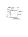
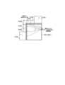
図1に示す従来の映像符号化方式の例では、オブジェクト#1は左上に動いており、オブジェクト#2は右上に動いているものとする。オブジェクト#1のみが含まれる符号化対象CUの左側に位置する隣接CU#1に対するインター予測では、オブジェクト#1の動きと同様の動きベクトル(MV#3)が適用される可能性が高い。符号化対象CUは、オブジェクト#1及びオブジェクト#2の両方を含むオブジェクト境界に位置するが、多くの領域をオブジェクト#1が占めることから、左側に隣接する隣接CU#1の動きベクトル(MV#2)と同様の動きベクトル(MV#1)が符号化対象CUに適用される可能性が高い。 In the example of the conventional video coding scheme shown in FIG. 1, it is assumed that
隣り合うCU同士の動きベクトルが同様である場合には、CUの境界領域の動きの連続性は高く、予測精度は高くなる可能性が高い。一方、図1の符号化対象CUの上側に隣接するCU#2はオブジェクト#2を多く含むことから、オブジェクト#2の動きと同様の動きベクトル(MV#3)が適用される可能性が高い。すなわち、符号化対象CUに適用する動きベクトル(MV#1)とCU#1に適用する動きベクトル(MV#3)は大きく異なる可能性が高い。このような隣り合うCU同士の動きベクトルが大きく異なる場合には、これらのCUのどちらか少なくとも一方にオブジェクト境界が含まれる可能性が高い。 When the motion vectors of adjacent CUs are similar, there is a high possibility that the continuity of motion in the boundary region of the CUs is high and the prediction accuracy is high. On the other hand, since
オブジェクト境界における動きベクトルの不連続性は予測精度の低下を招き、符号化効率が低下してしまう問題がある。HEVCでは、この問題を解決するため、ループフィルタにおいて、符号化対象CUに適用した動きベクトルと隣接ブロックに適用した動きベクトルとの差が予め規定した値より大きいか否かに応じて、ブロック歪を除去するデブロッキングフィルタを適用するか否かを制御する手法が導入されている。 Discontinuity of motion vectors at object boundaries leads to a decrease in prediction accuracy, and there is a problem that coding efficiency decreases. In HEVC, in order to solve this problem, in the loop filter, depending on whether the difference between the motion vector applied to the encoding target CU and the motion vector applied to the adjacent block is greater than a predetermined value, block distortion A technique is introduced to control whether or not to apply a deblocking filter that removes the .
しかしながら、予測(インター予測)においては、上記の動きベクトルの不連続性にかかわらず同一の処理が適用されているため、直交変換係数の伝送に必要な情報量がオブジェクト境界付近のブロックで増大し、符号化効率が低下してしまう問題がある。 However, in prediction (inter-prediction), the same processing is applied regardless of the motion vector discontinuity described above, so the amount of information required to transmit orthogonal transform coefficients increases in blocks near object boundaries. , there is a problem that the coding efficiency is lowered.
そこで、本発明は、インター予測を行う場合において符号化効率を向上させることが可能な予測画像補正装置、画像符号化装置、画像復号装置、及びプログラムを提供することを目的とする。 SUMMARY OF THE INVENTION Accordingly, it is an object of the present invention to provide a predictive image correction device, an image coding device, an image decoding device, and a program capable of improving coding efficiency when inter prediction is performed.
第1の特徴に係る予測画像補正装置は、画像を構成するブロックごとにインター予測をして得られた予測画像を補正する予測画像補正装置であって、前記インター予測が行われた対象ブロックに適用された動きベクトルと、前記対象ブロックに隣接する復号済みの1又は複数の隣接ブロックに適用された動きベクトルとの比較により、前記1又は複数の隣接ブロックについて前記対象ブロックとの動きの連続性を評価する連続性評価部と、前記連続性評価部により評価された前記連続性が予め定めた値よりも低い隣接ブロックが存在する場合に、前記連続性が予め定めた値よりも低い隣接ブロックの復号画像のうち前記対象ブロックとの境界領域の復号画像を用いて、前記対象ブロックの予測画像のうち前記連続性が予め定めた値よりも低い隣接ブロックとの境界領域の予測画像を補正する補正部とを備えることを要旨とする。 A predicted image correction device according to a first feature is a predicted image correction device that corrects a predicted image obtained by performing inter prediction for each block that constitutes an image, and Continuity of motion with the target block for the one or more neighboring blocks by comparing the applied motion vectors with the motion vectors applied to the decoded one or more neighboring blocks adjacent to the target block. and if there is an adjacent block whose continuity is lower than a predetermined value evaluated by the continuity evaluation unit, the adjacent block whose continuity is lower than the predetermined value Using the decoded image of the boundary area with the target block among the decoded images of the target block, correct the predicted image of the boundary area with the adjacent block whose continuity is lower than a predetermined value among the predicted images of the target block. and a correction unit.
第2の特徴に係る画像符号化装置は、インター予測を行うインター予測部と、第1の特徴に係る予測画像補正装置とを備えることを要旨とする。 An image coding apparatus according to the second feature is summarized to include an inter prediction unit that performs inter prediction, and a predicted image correction apparatus according to the first feature.
第3の特徴に係る画像復号装置は、インター予測を行うインター予測部と、第1の特徴に係る予測画像補正装置とを備えることを要旨とする。 An image decoding device according to the third feature is summarized to include an inter prediction unit that performs inter prediction, and a predicted image correction device according to the first feature.
第4の特徴に係るプログラムは、コンピュータを第1の特徴に係る予測画像補正装置として機能させることを要旨とする。 A program according to a fourth feature is gist to cause a computer to function as the predictive image correction device according to the first feature.
本発明によれば、インター予測を行う場合において符号化効率を向上させることが可能な予測画像補正装置、画像符号化装置、画像復号装置、及びプログラムを提供できる。 Advantageous Effects of Invention According to the present invention, it is possible to provide a predictive image correction device, an image coding device, an image decoding device, and a program capable of improving coding efficiency when inter prediction is performed.
図面を参照して、実施形態に係る画像符号化装置及び画像復号装置について説明する。実施形態に係る画像符号化装置及び画像復号装置は、MPEGに代表される動画の符号化及び復号をそれぞれ行う。以下の図面の記載において、同一又は類似の部分には同一又は類似の符号を付している。 An image encoding device and an image decoding device according to embodiments will be described with reference to the drawings. An image encoding device and an image decoding device according to an embodiment encode and decode a moving image represented by MPEG, respectively. In the following description of the drawings, the same or similar parts are denoted by the same or similar reference numerals.
<画像符号化装置>
まず、本実施形態に係る画像符号化装置について説明する。図2は、本実施形態に係る画像符号化装置1の構成を示す図である。<Image encoding device>
First, the image coding apparatus according to this embodiment will be described. FIG. 2 is a diagram showing the configuration of the
図2に示すように、画像符号化装置1は、ブロック分割部100と、減算部110と、変換・量子化部120と、エントロピー符号化部130と、逆量子化・逆変換部140と、合成部150と、メモリ部160と、予測部170とを備える。 As shown in FIG. 2, the
ブロック分割部100は、動画像を構成するフレーム(或いはピクチャ)単位の入力画像を複数のブロックに分割し、分割により得たブロックを減算部110に出力する。ブロックのサイズは、例えば32×32画素、16×16画素、8×8画素、又は4×4画素等である。ブロックの形状は正方形に限らず、長方形であってもよい。ブロックは、画像符号化装置1が符号化を行う単位及び画像復号装置が復号を行う単位である。以下において、かかるブロックをCU(Coding Unit)と称する。 The
減算部110は、ブロック分割部100から入力された符号化対象CUと、符号化対象CUを予測部170が予測して得た予測画像との差分(誤差)を表す予測残差を算出する。具体的には、減算部110は、CUの各画素値から予測画像の各画素値を減算することにより予測残差を算出し、算出した予測残差を変換・量子化部120に出力する。 The
変換・量子化部120は、CU単位で直交変換処理及び量子化処理を行う。変換・量子化部120は、変換部121と、量子化部122とを備える。 The transform/quantization unit 120 performs orthogonal transform processing and quantization processing on a per CU basis. The transform/quantization unit 120 includes a
変換部121は、減算部110から入力された予測残差に対して直交変換処理を行って直交変換係数を算出し、算出した直交変換係数を量子化部122に出力する。直交変換とは、例えば、離散コサイン変換(DCT:Discrete Cosine Transform)や離散サイン変換(DST:Discrete Sine Transform)、カルーネンレーブ変換(KLT: Karhunen Loeve Transform)等をいう。
量子化部122は、変換部121から入力された直交変換係数を量子化パラメータ(Qp)及び量子化行列を用いて量子化し、量子化した直交変換係数をエントロピー符号化部130及び逆量子化・逆変換部140に出力する。なお、量子化パラメータ(Qp)は、CU内の各直交変換係数に対して共通して適用されるパラメータであって、量子化の粗さを定めるパラメータである。量子化行列は、各直交変換係数を量子化する際の量子化値を要素として有する行列である。
エントロピー符号化部130は、量子化部122から入力された直交変換係数に対してエントロピー符号化を行い、データ圧縮を行って符号化ストリーム(ビットストリーム)を生成し、符号化ストリームを画像符号化装置1の外部に出力する。エントロピー符号化には、ハフマン符号やCABAC(Context-based Adaptive Binary Arithmetic Coding;コンテキスト適応型2値算術符号)等を用いることができる。なお、エントロピー符号化部130は、予測部170から予測に関する制御情報が入力され、入力された制御情報のエントロピー符号化も行う。 The
逆量子化・逆変換部140は、CU単位で逆量子化処理及び逆直交変換処理を行う。逆量子化・逆変換部140は、逆量子化部141と、逆変換部142とを備える。 The inverse quantization/
逆量子化部141は、量子化部122が行う量子化処理に対応する逆量子化処理を行う。具体的には、逆量子化部141は、量子化部122から入力された直交変換係数を、量子化パラメータ(Qp)及び量子化行列を用いて逆量子化することにより直交変換係数を復元し、復元した直交変換係数を逆変換部142に出力する。 The
逆変換部142は、変換部121が行う直交変換処理に対応する逆直交変換処理を行う。例えば、変換部121が離散コサイン変換を行った場合には、逆変換部142は逆離散コサイン変換を行う。逆変換部142は、逆量子化部141から入力された直交変換係数に対して逆直交変換処理を行って予測残差を復元し、復元した予測残差である復元予測残差を合成部150に出力する。 The
合成部150は、逆変換部142から入力された復元予測残差を、予測部170から入力された予測画像と画素単位で合成する。合成部150は、復元予測残差の各画素値と予測画像の各画素値を加算して符号化対象CUを再構成(復号)し、復号したCU単位の復号画像をメモリ部160に出力する。かかる復号画像は、再構成画像と称されることがある。 The synthesizing unit 150 synthesizes the restored prediction residual input from the
メモリ部160は、合成部150から入力された復号画像を記憶する。メモリ部160は、復号画像をフレーム単位で記憶する。メモリ部160は、記憶している復号画像を予測部170に出力する。さらに、メモリ部160は、インター予測部172において算出された動きベクトルをCUごとに記憶する。なお、メモリ部160は、複数のメモリにより構成されてもよい。また、合成部150とメモリ部160との間にループフィルタが設けられてもよい。 The
予測部170は、CU単位で予測を行う。予測部170は、イントラ予測部171と、インター予測部172と、予測画像補正部173と、切替部174とを備える。予測画像補正部173は、予測画像補正装置に相当する。 The prediction unit 170 makes a prediction in CU units. The prediction unit 170 includes an
イントラ予測部171は、メモリ部160に記憶された復号画像のうち、符号化対象CUの周辺にある復号画素値を参照してイントラ予測画像を生成し、生成したイントラ予測画像を切替部174に出力する。また、イントラ予測部171は、複数のイントラ予測モードの中から、対象CUに適用する最適なイントラ予測モードを選択し、選択したイントラ予測モードを用いてイントラ予測を行う。イントラ予測部171は、選択したイントラ予測モードに関する制御情報をエントロピー符号化部130に出力する。 The
インター予測部172は、メモリ部160に記憶された復号画像を参照画像として用いて、ブロックマッチングなどの手法により動きベクトルを算出し、符号化対象CUを予測してインター予測画像を生成し、生成したインター予測画像を当該動きベクトルと共に予測画像補正部173に出力する。また、インター予測部172は、CUごとに算出した動きベクトルをメモリ部160に出力し、当該動きベクトルをメモリ部160に記憶させる。インター予測部172は、複数の参照画像を用いるインター予測(典型的には、双予測)や、1つの参照画像を用いるインター予測(片方向予測)の中から最適なインター予測方法を選択し、選択したインター予測方法を用いてインター予測を行う。インター予測部172は、インター予測に関する制御情報(動きベクトル等)をエントロピー符号化部130に出力する。 The
予測画像補正部173は、インター予測部172から入力されたインター予測画像を補正し、補正後のインター予測画像を切替部174に出力する。具体的には、予測画像補正部173は、符号化対象CUに適用された動きベクトルをインター予測部172から取得し、符号化対象CUに隣接する復号済みのブロック群の動きベクトル及び復号済みのブロック群の符号化対象CUとの境界領域の復号画像をメモリ部160から取得し、取得した情報に基づいて符号化対象CUのインター予測画像を補正する。予測画像補正部173の詳細については後述する。 The predicted
切替部174は、イントラ予測部171から入力されるイントラ予測画像と予測画像補正部173から入力されるインター予測画像とを切り替えて、いずれかの予測画像を減算部110及び合成部150に出力する。 The
次に、予測画像補正部173について説明する。図3は、画像符号化装置1の予測画像補正部173の構成を示す図である。 Next, the predicted
図3に示すように、予測画像補正部173は、連続性評価部173aと、補正部173bとを備える。 As shown in FIG. 3, the predicted
連続性評価部173aは、符号化対象CUに隣接する復号済みの1又は複数の隣接CUに適用された動きベクトルをメモリ部160から取得する。例えば、図4に示すように、符号化対象CUに隣接する復号済みのCU#1乃至CU#7が復号済みCU群に含まれる場合、連続性評価部173aは、CU#1乃至CU#7のそれぞれについてインター予測に適用された動きベクトルを取得する。 The
なお、図4において、連続性評価部173aは、符号化対象CUの上側及び左側に隣接する復号済みCUの動きベクトルを取得しているが、右側や下側のCUが復号済みである場合には、右側や下側のCUに適用した動きベクトルをさらに取得してもよい。 In FIG. 4, the
そして、連続性評価部173aは、符号化対象CUに適用された動きベクトルと、隣接する復号済みCU群に適用された動きベクトルとの比較により、隣接する復号済みCU群について符号化対象CUとの動きの連続性を評価し、評価結果を補正部173bに出力する。 Then, the
具体的には、連続性評価部173aは、符号化対象CUに適用されるベクトルと復号済みCUの動きベクトルとのL1ノルムが予め規定した閾値未満である場合には連続性が高いと評価する。一方、当該L1ノルムが閾値以上である場合には連続性が低いと評価する。但し、連続性の指標値としてはL1ノルムに限定されるものではなく、他の指標値を用いてもよい。 Specifically, the
例えば、図5に示すように、連続性評価部173aは、符号化対象CUに隣接する復号済みのCU#1乃至CU#7のそれぞれの動きベクトルについて、符号化対象CUの動きベクトルとの差(距離)を表すL1ノルムを算出し、CU#1乃至CU#7のそれぞれについて算出したL1ノルムを閾値と比較する。 For example, as shown in FIG. 5, the
図5に示す例において、CU#1に対応するL1ノルム、CU#2に対応するL1ノルム、CU#3に対応するL1ノルム、CU#4に対応するL1ノルム、及びCU#5に対応するL1ノルムは、閾値以上であるため、これらの隣接CUは符号化対象CUとの連続性が低いということになる。一方、CU#6に対応するL1ノルム及びCU#7に対応するL1ノルムは、閾値未満であるため、これらの隣接CUは符号化対象CUとの連続性が高いということになる。なお、CU#1乃至CU#7のいずれも連続性が高いと評価された場合、補正部173bによる符号化対象CUのインター予測画像の補正を省略してもよい。 In the example shown in FIG. 5, the L1 norm corresponding to
本実施形態において、動きベクトルは、X軸及びY軸方向のベクトル値のほか、参照する復号済みフレームを示すフラグ(例えば、HEVCにおけるinter_pred_idc,ref_idx)を含むものとする。連続性評価部173aは、隣接ブロックとの動きベクトルの連続性の評価にあたっては、符号化対象CUを含むフレーム(現フレーム)と符号化対象CUの参照先の復号済みフレームとの時間的な距離(POC距離)と、現フレームと隣接する復号済みCUの参照先の復号済みフレームとのPOC距離とに応じて、当該隣接する復号済みCUに適用した動きベクトルのベクトル値をスケーリングしたのちに連続性を評価してもよい。 In this embodiment, the motion vector includes vector values in the X-axis and Y-axis directions as well as flags indicating the decoded frame to be referenced (for example, inter_pred_idc and ref_idx in HEVC). When evaluating continuity of motion vectors with adjacent blocks, the
補正部173bは、符号化対象CUのインター予測画像を補正するために、符号化対象CUに隣接する復号済みCU群の復号画像のうち、少なくとも符号化対象CUとの境界領域の復号画像をメモリ部160から取得する。 In order to correct the inter prediction image of the CU to be coded, the
例えば、図4に示すように、補正部173bは、符号化対象CUに隣接する復号済みのCU#1乃至CU#7のそれぞれの復号画像のうち、符号化対象CUとの境界領域の復号画像をメモリ部160から取得する。 For example, as shown in FIG. 4, the
なお、符号化対象CUとの境界領域とは、符号化対象CUに隣接する復号済み画素を含む領域をいうが、符号化対象CUからN画素(N>1)までの復号済み画素からなる領域を境界領域としてもよい。 Note that the boundary area with the CU to be coded refers to an area including decoded pixels adjacent to the CU to be coded, and an area composed of decoded pixels from the CU to be coded to N pixels (N>1). may be used as the border region.
また、図4に示す例において、補正部173bは、符号化対象CUに隣接する復号済みのCU#1乃至CU#7のすべてについて境界領域の復号画像を取得せずに、CU#1乃至CU#7のうち連続性評価部173aにより連続性が低いと評価されたCU#1乃至CU#5(図5参照)のみについて境界領域の復号画像を取得してもよい。 Further, in the example illustrated in FIG. 4 , the
そして、補正部173bは、連続性評価部173aにより連続性が低いと評価された隣接CU(所定隣接ブロック)が存在する場合に、当該隣接CUの復号画像のうち少なくとも符号化対象CUとの境界領域の復号画像を用いて、符号化対象CUのインター予測画像のうち少なくとも当該隣接CUとの境界領域の予測画像を補正する。 Then, when there is an adjacent CU (predetermined adjacent block) evaluated as having low continuity by the
具体的には、補正部173bは、連続性評価部173aにおいて連続性が低いと評価された隣接CUと符号化対象CUとのブロック境界について、符号化対象CUの予測画像を当該隣接CUの復号画像の値を用いて補正する。例えば、図6に示すように、補正部173bは、連続性評価部173aにおいて連続性が低いと評価された隣接CU#1乃至CU#5と符号化対象CUとのブロック境界について、符号化対象CUのインター予測画像を当該隣接CU#1乃至CU#5の復号画像の値を用いて補正する。 Specifically, the
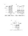
ここで、補正部173bによる補正の方法の具体例について説明する。符号化対象CU(幅M、高さN)に適用する動きベクトルを用いて生成したインター予測画像をpred[i,j](i=0…M-1,j=0…N-1)とし、隣接する復号済みCUの復号画像をrec[i,j](i=-1,j=-1…N及びi=-1…M,j=-1)とするとき、補正部173bは、図7に示す式により補正後のインター予測画像pred’[i,j]を算出する。 Here, a specific example of the correction method by the
図7(a)は符号化対象CUのインター予測画像の左側のブロック境界領域を補正する例を示し、図7(b)は符号化対象CUのインター予測画像の上側のブロック境界領域を補正する例を示し、図7(c)は符号化対象CUのインター予測画像の左上の角のブロック境界領域を補正する例を示している。インター予測画像において、ブロック境界から2画素までをブロック境界領域として補正しているが、ブロック境界からM画素(M≧3)までをブロック境界領域として補正してもよい。 FIG. 7A shows an example of correcting the left block boundary region of the inter-predicted image of the CU to be coded, and FIG. 7B shows an example of correcting the upper block boundary region of the inter-predicted image of the CU to be coded. An example is shown, and FIG. 7C shows an example of correcting the block boundary area at the upper left corner of the inter-predicted image of the encoding target CU. In the inter-predicted image, up to two pixels from the block boundary are corrected as the block boundary area, but up to M pixels (M≧3) from the block boundary may be corrected as the block boundary area.
このようにして符号化対象CUのインター予測画像を補正すると、補正部173bは、補正後のインター予測画像を、切替部174を介して減算部110及び合成部150に出力する。 After correcting the inter-predicted image of the encoding target CU in this way, the correcting
次に、予測画像補正部173の動作について説明する。図8は、画像符号化装置1の予測画像補正部173の動作を示す図である。 Next, the operation of the predicted
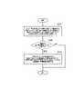
図8に示すように、ステップS101において、連続性評価部173aは、インター予測が行われた符号化対象CUに適用された動きベクトルと、復号済みの隣接ブロックに適用された動きベクトルとの比較により、隣接ブロックについて符号化対象CUとの動きの連続性を評価する。 As shown in FIG. 8, in step S101, the
連続性評価部173aにより評価された連続性が所定値よりも低い所定隣接ブロックが存在する場合(ステップS102:YES)、ステップS103において、補正部173bは、所定隣接ブロックの復号画像のうち少なくとも符号化対象CUとの境界領域の復号画像を用いて、符号化対象CUの予測画像のうち少なくとも所定隣接ブロックとの境界領域の予測画像を補正する。 If there is a predetermined adjacent block whose continuity is lower than the predetermined value evaluated by the
このように、予測画像補正部173によれば、動きベクトルの不連続性を考慮して予測画像を補正することにより、オブジェクト境界付近のブロックについて直交変換係数の伝送に必要な情報量を低減できるため、インター予測を行う場合における符号化効率を向上させることができる。 As described above, according to the predicted
<画像復号装置>
次に、本実施形態に係る画像復号装置について説明する。但し、上記の画像符号化装置1と同様な動作については重複する説明を省略する。図9は、本実施形態に係る画像復号装置2の構成を示す図である。<Image decoding device>
Next, the image decoding device according to this embodiment will be described. However, overlapping descriptions of operations similar to those of the
図9に示すように、画像復号装置2は、エントロピー復号部200と、逆量子化・逆変換部210と、合成部220と、メモリ部230と、予測部240とを備える。 As shown in FIG. 9 , the
エントロピー復号部200は、画像符号化装置1により生成された符号化ストリームを復号し、量子化された直交変換係数を逆量子化・逆変換部210に出力する。また、エントロピー復号部200は、予測(イントラ予測及びインター予測)に関する制御情報を取得し、取得した制御情報を予測部240に出力する。 The
逆量子化・逆変換部210は、CU単位で逆量子化処理及び逆直交変換処理を行う。逆量子化・逆変換部210は、逆量子化部211と、逆変換部212とを備える。 The inverse quantization/inverse transform unit 210 performs inverse quantization processing and inverse orthogonal transform processing on a per CU basis. The inverse quantization/inverse transform unit 210 includes an
逆量子化部211は、画像符号化装置1の量子化部122が行う量子化処理に対応する逆量子化処理を行う。逆量子化部211は、エントロピー復号部200から入力された量子化直交変換係数を、量子化パラメータ(Qp)及び量子化行列を用いて逆量子化することにより、復号対象CUの直交変換係数を復元し、復元した直交変換係数を逆変換部212に出力する。 The
逆変換部212は、画像符号化装置1の変換部121が行う直交変換処理に対応する逆直交変換処理を行う。逆変換部212は、逆量子化部211から入力された直交変換係数に対して逆直交変換処理を行って予測残差を復元し、復元した予測残差(復元予測残差)を合成部220に出力する。 The
合成部220は、逆変換部212から入力された予測残差と、予測部240から入力された予測画像とを画素単位で合成することにより、元のCUを再構成(復号)し、CU単位の復号画像をメモリ部230に出力する。 The synthesizing
メモリ部230は、合成部220から入力された復号画像を記憶する。メモリ部230は、復号画像をフレーム単位で記憶する。さらに、メモリ部230は、インター予測部242において算出された動きベクトルをCUごとに記憶する。メモリ部230は、フレーム単位の復号画像を画像復号装置2の外部に出力する。なお、メモリ部230は、複数のメモリにより構成されてもよい。合成部220とメモリ部230との間にループフィルタが設けられてもよい。 The
予測部240は、CU単位で予測を行う。予測部240は、イントラ予測部241と、インター予測部242と、予測画像補正部243と、切替部244とを備える。予測画像補正部243は、予測画像補正装置に相当する。 The prediction unit 240 makes predictions in CU units. The prediction unit 240 includes an
イントラ予測部241は、メモリ部230に記憶された復号画像を参照し、エントロピー復号部200から入力された制御情報に従って、復号対象CUをイントラ予測により予測することによりイントラ予測画像を生成し、生成したイントラ予測画像を切替部244に出力する。 The
インター予測部242は、メモリ部230に記憶された復号画像を参照画像として用いて、復号対象CUをインター予測により予測する。インター予測部242は、エントロピー復号部200から入力された制御情報に従ってインター予測を行うことによりインター予測画像を生成し、生成したインター予測画像を予測画像補正部243に出力する。 The
予測画像補正部243は、インター予測部242から入力されたインター予測画像を補正し、補正後のインター予測画像を切替部244に出力する。具体的には、予測画像補正部243は、復号対象CUに適用された動きベクトルをインター予測部242から取得し、復号対象CUに隣接する復号済みのブロック群の動きベクトル及び復号済みのブロック群の復号対象CUとの境界領域の復号画像をメモリ部230から取得し、取得した情報に基づいて復号対象CUのインター予測画像を補正する。予測画像補正部243の詳細については後述する。 The predicted
切替部244は、イントラ予測部241から入力されるイントラ予測画像と予測画像補正部243から入力されるインター予測画像とを切り替えて、いずれかの予測画像を合成部220に出力する。 The
次に、予測画像補正部243について説明する。図10は、画像復号装置2の予測画像補正部243の構成を示す図である。 Next, the predicted
図10に示すように、予測画像補正部243は、連続性評価部243aと、補正部243bとを備える。連続性評価部243a及び補正部243bの動作は、画像符号化装置1の連続性評価部173a及び補正部173bの動作と同様であるため、以下では連続性評価部243a及び補正部243bの動作について簡単に説明する。 As shown in FIG. 10, the predicted
連続性評価部243aは、復号対象CUに隣接する復号済みの1又は複数の隣接CUに適用された動きベクトルをメモリ部230から取得する。 The
そして、連続性評価部243aは、復号対象CUに適用された動きベクトルと、隣接する復号済みCU群に適用された動きベクトルとの比較により、隣接する復号済みCU群について復号対象CUとの動きの連続性を評価し、評価結果を補正部243bに出力する。 Then, the
補正部243bは、復号対象CUのインター予測画像を補正するために、復号対象CUに隣接する復号済みCU群の復号画像のうち、少なくとも復号対象CUとの境界領域の復号画像をメモリ部230から取得する。 In order to correct the inter-prediction image of the decoding target CU, the
そして、補正部243bは、連続性評価部243aにより連続性が低いと評価された隣接CU(所定隣接ブロック)が存在する場合に、当該隣接CUの復号画像のうち少なくとも復号対象CUとの境界領域の復号画像を用いて、復号対象CUのインター予測画像のうち少なくとも当該隣接CUとの境界領域の予測画像を補正する。具体的には、補正部243bは、連続性評価部243aにおいて連続性が低いと評価された隣接CUと復号対象CUとのブロック境界について、復号対象CUの予測画像を当該隣接CUの復号画像の値を用いて補正する。 Then, when there is an adjacent CU (predetermined adjacent block) evaluated as having low continuity by the
このようにして復号対象CUのインター予測画像を補正すると、補正部243bは、補正後のインター予測画像を、切替部244を介して合成部220に出力する。 After correcting the inter-predicted image of the CU to be decoded in this way, the correcting
なお、画像復号装置2の予測画像補正部243の動作フローについては図8と同様であるが、図8に示した動作フローにおいて「符号化対象CU」を「復号対象CU」と読み替える。 The operation flow of the prediction
このように、予測画像補正部243によれば、動きベクトルの不連続性を考慮して予測画像を補正することにより、インター予測を行う場合における符号化効率を向上させることができる。 As described above, the predicted
<変更例>
上記の実施形態において、復号済みの隣接ブロックとの連続性の評価において、符号化対象CU(又は復号対象CU)に適用した動きベクトルと復号済みの隣接CUに適用した動きベクトルとの比較により連続性が高いか否かを評価し、連続性が低いことに応じてインター予測画像を補正していた。<Change example>
In the above embodiment, in evaluating the continuity with the decoded adjacent block, the motion vector applied to the encoding target CU (or the decoding target CU) is compared with the motion vector applied to the decoded adjacent CU. The inter-prediction image is corrected according to whether the continuity is high or not, and the continuity is low.
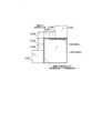
しかしながら、かかる方法において、補正が適切に機能しない場合がある。例えば、図11に示すように、符号化対象CUと符号化対象CUの上側の隣接CU#2とは動きベクトルが互いに異なるため、符号化対象CUにおける上側のブロック境界領域に対して補正が行われることになる。 However, in such methods, the correction may not work properly. For example, as shown in FIG. 11, since the motion vectors of the CU to be encoded and the
しかしながら、オブジェクト#1及び#2のオブジェクト境界は隣接CU#2における下側のブロック境界領域に含まれている。このような場合、符号化対象CUのインター予測画像に補正を施すと、インター予測画像の劣化を引き起こす可能性がある。 However, the object boundaries of
そこで、本変更例では、上記の実施形態と同様な動きベクトルの比較に加えて、復号済みの隣接ブロックにおける予測残差(残差信号)のエネルギーに応じて補正の有無を決定する。 Therefore, in this modified example, in addition to comparison of motion vectors as in the above embodiment, whether or not to perform correction is determined according to the energy of the prediction residual (residual signal) in the decoded adjacent block.
図11に示す例において、オブジェクト#1及び#2のオブジェクト境界は隣接CU#2における下側のブロック境界領域に含まれているため、当該下側のブロック境界領域における予測残差のエネルギーは大きくなる可能性が高い。かかる場合、符号化対象CUのインター予測画像に対して補正を行わないようにする。一方、下側のブロック境界領域における予測残差のエネルギーが小さい場合には、符号化対象CUのインター予測画像に対して補正を行うようにする。 In the example shown in FIG. 11, since the object boundaries of
本変更例に係る画像符号化装置1について説明する。本変更例において、画像符号化装置1のメモリ部160は、符号化対象CUに隣接する復号済みCUの予測残差を記憶する。各ブロック処理において得られた予測残差をメモリ部160に記憶させることで、その後のブロックの処理の際に、メモリ部160に記憶された予測残差を利用できる。 The
メモリ部160は、減算部110が出力する予測残差を記憶してもよいし、逆変換部142が出力する予測残差を記憶してもよい。予測画像補正部173は、メモリ部160に記憶された隣接ブロックの予測残差のうち、符号化対象CUとの境界領域の予測残差を取得する。 The
図12は、本変更例に係る予測画像補正部173の構成を示す図である。図12に示すように、本変更例に係る予測画像補正部173は、上記の実施形態と同様な連続性評価部173a及び補正部173bに加えて、残差エネルギー算出部173cを備える。 FIG. 12 is a diagram showing the configuration of the predicted
残差エネルギー算出部173cは、符号化対象CUに隣接する復号済み隣接ブロックのブロック境界付近の予測残差をメモリ部160から取得し、取得した復号済み隣接ブロックのブロック境界付近の予測残差のエネルギーを算出し、エネルギーの算出値(隣接残差エネルギー)を補正部173bに出力する。 The residual
例えば、図13に示すように、残差エネルギー算出部173cは、符号化対象CUに隣接する復号済み隣接ブロックCU#1乃至CU#7のそれぞれのブロック境界付近の予測残差のエネルギーを算出する。エネルギーを算出する領域は符号化対象CUのブロック境界から法線方向に予め規定したライン数分とすることとする。但し、ライン数はブロックサイズに応じて可変であってもよい。 For example, as shown in FIG. 13, the
また、符号化対象CUの角では、水平垂直方向に規定ライン数分の領域を残差エネルギー算出の領域とする。例えば、左上の角については、符号化対象CUの左上座標を(0,0)とした場合に、(-N,-N)から(-1,-1)までの領域を残差エネルギー算出の領域とする(Nはあらかじめ規定したライン数)。 At the corners of the CU to be coded, an area for a prescribed number of lines in the horizontal and vertical directions is used as an area for residual energy calculation. For example, for the upper left corner, if the upper left coordinates of the CU to be encoded are (0, 0), the area from (-N, -N) to (-1, -1) is used for residual energy calculation. area (N is the number of lines defined in advance).
具体的には、残差エネルギー算出部173cは、算出領域内の予測残差の絶対値の平均を残差エネルギーとすることができる。但し、予測残差のエネルギーを領域ごとに算出する指標であれば、二乗和の平均など他の指標であってもかまわない。 Specifically, the
なお、残差エネルギー算出部173cは、符号化対象CUに隣接する復号済みのCU#1乃至CU#7のすべてについて境界領域の予測残差のエネルギーを算出せずに、CU#1乃至CU#7のうち連続性評価部173aにより連続性が低いと評価されたCU#1乃至CU#5(図5参照)のみについて境界領域の予測残差のエネルギーを算出してもよい。 Note that the residual
補正部173bは、連続性評価部173aにより連続性が低いと評価された隣接ブロックのうち、残差エネルギー算出部173cにより算出されたエネルギーが予め規定した閾値よりも小さい隣接ブロックの境界領域の復号画像を用いて、符号化対象CUのインター予測画像を補正する。 The
例えば、図14に示すように、符号化対象CUに隣接するCU#1乃至CU#7のうち連続性評価部173aによりCU#1乃至CU#5の連続性が低いと評価され、且つ、残差エネルギー算出部173cにより算出されたエネルギーが閾値よりも小さいCUがCU#1乃至CU#3であるとする。すなわち、CU#4乃至CU#7について残差エネルギー算出部173cにより算出されたエネルギーは閾値よりも大きい。 For example, as illustrated in FIG. 14, the
かかる場合、補正部173bは、CU#1乃至CU#3のブロック境界領域の復号画像を用いて、符号化対象CUのインター予測画像のブロック境界領域を補正する。一方、補正部173bは、CU#4乃至CU#7のブロック境界領域の復号画像を符号化対象CUのインター予測画像の補正に用いない。 In such a case, the
なお、本変更例においては画像符号化装置1を例に挙げて説明したが、本変更例に係る動作を画像復号装置2にも適用可能である。 Although the
<その他の実施形態>
上記の実施形態及び変更例において、符号化対象CU(又は復号対象CU)が複数の小領域に分割される場合について特に考慮していなかった。しかしながら、符号化対象CU(又は復号対象CU)が複数の小領域に分割される場合にも本発明を適用可能である。<Other embodiments>
In the above embodiments and modifications, no particular consideration was given to the case where the CU to be coded (or the CU to be decoded) is divided into a plurality of small regions. However, the present invention can also be applied when a CU to be coded (or a CU to be decoded) is divided into a plurality of small regions.
例えば、図15に示すように、符号化対象CUの内部を小領域に分割し、小領域ごとに異なる動きベクトルを適用できる場合、連続性評価部173aは、隣接する復号済みCUに最も近い位置の小領域に適用した動きベクトルと当該隣接する復号済みCUに適用した動きベクトルとの動きの連続性を評価する。 For example, as shown in FIG. 15, when the interior of the encoding target CU is divided into small regions and different motion vectors can be applied to each small region, the
画像符号化装置1が行う各処理をコンピュータに実行させるプログラム及び画像復号装置2が行う各処理をコンピュータに実行させるプログラムにより提供されてもよい。また、プログラムは、コンピュータ読取り可能媒体に記録されていてもよい。コンピュータ読取り可能媒体を用いれば、コンピュータにプログラムをインストールすることが可能である。ここで、プログラムが記録されたコンピュータ読取り可能媒体は、非一過性の記録媒体であってもよい。非一過性の記録媒体は、特に限定されるものではないが、例えば、CD-ROMやDVD-ROM等の記録媒体であってもよい。 It may be provided by a program that causes a computer to execute each process performed by the
また、画像符号化装置1が行う各処理を実行する回路を集積化し、画像符号化装置1を半導体集積回路(チップセット、SoC)として構成してもよい。同様に、画像復号装置2が行う各処理を実行する回路を集積化し、画像復号装置2を半導体集積回路(チップセット、SoC)として構成してもよい。 Alternatively, the
以上、図面を参照して実施形態について詳しく説明したが、具体的な構成は上述のものに限られることはなく、要旨を逸脱しない範囲内において様々な設計変更等をすることが可能である。 Although the embodiments have been described in detail with reference to the drawings, the specific configuration is not limited to the above, and various design changes can be made without departing from the spirit of the invention.
1 :画像符号化装置
2 :画像復号装置
100 :ブロック分割部
110 :減算部
120 :変換・量子化部
121 :変換部
122 :量子化部
130 :エントロピー符号化部
140 :逆量子化・逆変換部
141 :逆量子化部
142 :逆変換部
150 :合成部
160 :メモリ部
170 :予測部
171 :イントラ予測部
172 :インター予測部
173 :予測画像補正部
173a :連続性評価部
173b :補正部
173c :残差エネルギー算出部
174 :切替部
200 :エントロピー復号部
210 :逆量子化・逆変換部
211 :逆量子化部
212 :逆変換部
220 :合成部
230 :メモリ部
240 :予測部
241 :イントラ予測部
242 :インター予測部
243 :予測画像補正部
243a :連続性評価部
243b :補正部
244 :切替部1: image coding device 2: image decoding device 100: block division unit 110: subtraction unit 120: transformation/quantization unit 121: transformation unit 122: quantization unit 130: entropy coding unit 140: inverse quantization/inverse transformation Unit 141 : Inverse quantization unit 142 : Inverse transform unit 150 : Synthesis unit 160 : Memory unit 170 : Prediction unit 171 : Intra prediction unit 172 : Inter prediction unit 173 : Prediction
Claims (6)
Translated fromJapanese前記インター予測が行われた対象ブロックに適用された動きベクトルと、前記対象ブロックに隣接する復号済みの1又は複数の隣接ブロックに適用された動きベクトルとの比較により、前記1又は複数の隣接ブロックについて前記対象ブロックとの動きの連続性を評価する連続性評価部と、
前記隣接ブロックの復号画像のうち前記対象ブロックとの境界領域の復号画像を用いて、前記対象ブロックの予測画像のうち前記隣接ブロックとの境界領域の予測画像を補正する補正部と、を備え、
前記対象ブロックは、複数の小領域に分割され、
前記補正部は、前記小領域ごとに評価した前記連続性に基づいて、前記予測画像を補正することを特徴とする予測画像補正装置。A predicted image correction device for correcting a predicted image obtained by performing inter prediction for each block constituting an image,
By comparing the motion vector applied to the inter-predicted target block and the motion vector applied to one or more decoded neighboring blocks adjacent to the target block, the one or more neighboring blocks a continuity evaluation unit that evaluates the continuity of motion with the target block for
a correction unit that corrects a predicted image ofa boundary region with the adjacent block among the predicted images of the target block using a decoded image of a boundary region withthe target block among the decoded images of the adjacent block; prepared,
The target block is divided into a plurality of small areas,
The predicted image correction device, wherein the correction unit corrects the predicted image based on the continuity evaluated for each of the small regions .
前記インター予測が行われた対象ブロックに適用された動きベクトルと、前記対象ブロックに隣接する復号済みの1又は複数の隣接ブロックに適用された動きベクトルとの比較により、前記1又は複数の隣接ブロックについて前記対象ブロックとの動きの連続性を評価する連続性評価部と、By comparing the motion vector applied to the inter-predicted target block and the motion vector applied to one or more decoded neighboring blocks adjacent to the target block, the one or more neighboring blocks a continuity evaluation unit that evaluates the continuity of motion with the target block for
前記隣接ブロックの復号画像のうち前記対象ブロックとの境界領域の復号画像を用いて、前記対象ブロックの予測画像のうち前記隣接ブロックとの境界領域の予測画像を補正する補正部と、を備え、a correction unit that corrects a predicted image of a boundary region with the adjacent block among the predicted images of the target block using a decoded image of a boundary region with the target block among the decoded images of the adjacent block,
前記補正部は、前記隣接ブロックの予測残差を更に用いて前記補正を行うことを特徴とする予測画像補正装置。The prediction image correction device, wherein the correction unit performs the correction by further using the prediction residual of the adjacent block.
前記補正部は、前記連続性が予め定めた値よりも低い前記隣接ブロックが存在し、かつ前記残差エネルギー算出部により算出された前記エネルギーが閾値よりも小さい場合に、前記補正を行うことを特徴とする請求項2に記載の予測画像補正装置。When there is the adjacent block whose continuity is lower than a predetermined value evaluated by the continuity evaluation unit, the prediction residual of the adjacent block whose continuity is lower than a predetermined value is further comprising a residual energy calculation unit that calculates the energy of the prediction residual of the boundary region with the target block,
The correction unit performs the correction when there is the adjacent block whose continuity is lower than a predetermined value and when the energy calculated by the residual energy calculation unit is smaller than a threshold. 3. The predictive image correction device according to claim 2.
Priority Applications (1)
| Application Number | Priority Date | Filing Date | Title |
|---|---|---|---|
| JP2018178118AJP7228980B2 (en) | 2018-09-21 | 2018-09-21 | Predictive image correction device, image coding device, image decoding device, and program |
Applications Claiming Priority (1)
| Application Number | Priority Date | Filing Date | Title |
|---|---|---|---|
| JP2018178118AJP7228980B2 (en) | 2018-09-21 | 2018-09-21 | Predictive image correction device, image coding device, image decoding device, and program |
Publications (2)
| Publication Number | Publication Date |
|---|---|
| JP2020053725A JP2020053725A (en) | 2020-04-02 |
| JP7228980B2true JP7228980B2 (en) | 2023-02-27 |
Family
ID=69994275
Family Applications (1)
| Application Number | Title | Priority Date | Filing Date |
|---|---|---|---|
| JP2018178118AActiveJP7228980B2 (en) | 2018-09-21 | 2018-09-21 | Predictive image correction device, image coding device, image decoding device, and program |
Country Status (1)
| Country | Link |
|---|---|
| JP (1) | JP7228980B2 (en) |
Families Citing this family (1)
| Publication number | Priority date | Publication date | Assignee | Title |
|---|---|---|---|---|
| JP7449690B2 (en)* | 2018-12-28 | 2024-03-14 | 日本放送協会 | Inter prediction device, image encoding device, image decoding device, and program |
Citations (5)
| Publication number | Priority date | Publication date | Assignee | Title |
|---|---|---|---|---|
| JP2007503775A (en) | 2003-08-26 | 2007-02-22 | トムソン ライセンシング | Method and apparatus for encoding hybrid intra-inter coded blocks |
| JP2011030175A (en) | 2009-07-01 | 2011-02-10 | Sony Corp | Image processing unit and method |
| JP2011066569A (en) | 2009-09-16 | 2011-03-31 | Nippon Telegr & Teleph Corp <Ntt> | Method, device and program for generating prediction signal |
| JP2014131162A (en) | 2012-12-28 | 2014-07-10 | Nippon Telegr & Teleph Corp <Ntt> | Intra-prediction encoding method, intra-prediction decoding method, intra-prediction encoding device, intra-prediction decoding device, program therefor, and program recorded recording medium |
| WO2018123800A1 (en) | 2016-12-27 | 2018-07-05 | パナソニック インテレクチュアル プロパティ コーポレーション オブ アメリカ | Encoding device, decoding device, encoding method, and decoding method |
- 2018
- 2018-09-21JPJP2018178118Apatent/JP7228980B2/enactiveActive
Patent Citations (5)
| Publication number | Priority date | Publication date | Assignee | Title |
|---|---|---|---|---|
| JP2007503775A (en) | 2003-08-26 | 2007-02-22 | トムソン ライセンシング | Method and apparatus for encoding hybrid intra-inter coded blocks |
| JP2011030175A (en) | 2009-07-01 | 2011-02-10 | Sony Corp | Image processing unit and method |
| JP2011066569A (en) | 2009-09-16 | 2011-03-31 | Nippon Telegr & Teleph Corp <Ntt> | Method, device and program for generating prediction signal |
| JP2014131162A (en) | 2012-12-28 | 2014-07-10 | Nippon Telegr & Teleph Corp <Ntt> | Intra-prediction encoding method, intra-prediction decoding method, intra-prediction encoding device, intra-prediction decoding device, program therefor, and program recorded recording medium |
| WO2018123800A1 (en) | 2016-12-27 | 2018-07-05 | パナソニック インテレクチュアル プロパティ コーポレーション オブ アメリカ | Encoding device, decoding device, encoding method, and decoding method |
Also Published As
| Publication number | Publication date |
|---|---|
| JP2020053725A (en) | 2020-04-02 |
Similar Documents
| Publication | Publication Date | Title |
|---|---|---|
| KR100813963B1 (en) | Lossless encoding and decoding method for video | |
| KR20190033624A (en) | Inter prediction method and apparatus in video coding system | |
| US20210014489A1 (en) | Intra prediction device, image encoding device, image decoding device and program | |
| US11785242B2 (en) | Video processing methods and apparatuses of determining motion vectors for storage in video coding systems | |
| JP7749052B2 (en) | Prediction device, encoding device, decoding device, and program | |
| JP2023168518A (en) | Prediction block generation device, image encoder, image decoder, and program | |
| JP2025142371A (en) | Image decoding device and image decoding method | |
| JP7100194B2 (en) | Image coding device, image decoding device, and program | |
| JP7228980B2 (en) | Predictive image correction device, image coding device, image decoding device, and program | |
| JP6528635B2 (en) | Moving picture coding apparatus, moving picture coding method, and computer program for moving picture coding | |
| US11812015B2 (en) | Image encoding device, image decoding device and program | |
| JP7474772B2 (en) | Encoding device, decoding device, and program | |
| JP7332385B2 (en) | Intra prediction device, image coding device, image decoding device, and program | |
| JP7659103B2 (en) | Inter prediction device, image encoding device, image decoding device, and program | |
| JP7444599B2 (en) | Intra prediction device, image encoding device, image decoding device, and program | |
| JP7531683B2 (en) | Encoding device, decoding device, and program | |
| WO2023217235A1 (en) | Prediction refinement with convolution model | |
| JP2022145499A (en) | Encoding device and method |
Legal Events
| Date | Code | Title | Description |
|---|---|---|---|
| RD02 | Notification of acceptance of power of attorney | Free format text:JAPANESE INTERMEDIATE CODE: A7422 Effective date:20200529 | |
| RD05 | Notification of revocation of power of attorney | Free format text:JAPANESE INTERMEDIATE CODE: A7425 Effective date:20200612 | |
| A621 | Written request for application examination | Free format text:JAPANESE INTERMEDIATE CODE: A621 Effective date:20210820 | |
| A977 | Report on retrieval | Free format text:JAPANESE INTERMEDIATE CODE: A971007 Effective date:20220721 | |
| A131 | Notification of reasons for refusal | Free format text:JAPANESE INTERMEDIATE CODE: A131 Effective date:20220726 | |
| A521 | Request for written amendment filed | Free format text:JAPANESE INTERMEDIATE CODE: A523 Effective date:20220926 | |
| TRDD | Decision of grant or rejection written | ||
| A01 | Written decision to grant a patent or to grant a registration (utility model) | Free format text:JAPANESE INTERMEDIATE CODE: A01 Effective date:20230117 | |
| A61 | First payment of annual fees (during grant procedure) | Free format text:JAPANESE INTERMEDIATE CODE: A61 Effective date:20230214 | |
| R150 | Certificate of patent or registration of utility model | Ref document number:7228980 Country of ref document:JP Free format text:JAPANESE INTERMEDIATE CODE: R150 |