JP7228781B2 - Purification device and purification method - Google Patents
Purification device and purification methodDownload PDFInfo
- Publication number
- JP7228781B2 JP7228781B2JP2018187783AJP2018187783AJP7228781B2JP 7228781 B2JP7228781 B2JP 7228781B2JP 2018187783 AJP2018187783 AJP 2018187783AJP 2018187783 AJP2018187783 AJP 2018187783AJP 7228781 B2JP7228781 B2JP 7228781B2
- Authority
- JP
- Japan
- Prior art keywords
- light
- cleaning agent
- pressure
- ejection
- trajectory
- Prior art date
- Legal status (The legal status is an assumption and is not a legal conclusion. Google has not performed a legal analysis and makes no representation as to the accuracy of the status listed.)
- Active
Links
Images


Classifications
- B—PERFORMING OPERATIONS; TRANSPORTING
- B05—SPRAYING OR ATOMISING IN GENERAL; APPLYING FLUENT MATERIALS TO SURFACES, IN GENERAL
- B05B—SPRAYING APPARATUS; ATOMISING APPARATUS; NOZZLES
- B05B12/00—Arrangements for controlling delivery; Arrangements for controlling the spray area
- B05B12/08—Arrangements for controlling delivery; Arrangements for controlling the spray area responsive to condition of liquid or other fluent material to be discharged, of ambient medium or of target ; responsive to condition of spray devices or of supply means, e.g. pipes, pumps or their drive means
- B05B12/12—Arrangements for controlling delivery; Arrangements for controlling the spray area responsive to condition of liquid or other fluent material to be discharged, of ambient medium or of target ; responsive to condition of spray devices or of supply means, e.g. pipes, pumps or their drive means responsive to conditions of ambient medium or target, e.g. humidity, temperature position or movement of the target relative to the spray apparatus
- B05B12/124—Arrangements for controlling delivery; Arrangements for controlling the spray area responsive to condition of liquid or other fluent material to be discharged, of ambient medium or of target ; responsive to condition of spray devices or of supply means, e.g. pipes, pumps or their drive means responsive to conditions of ambient medium or target, e.g. humidity, temperature position or movement of the target relative to the spray apparatus responsive to distance between spray apparatus and target
- A—HUMAN NECESSITIES
- A61—MEDICAL OR VETERINARY SCIENCE; HYGIENE
- A61L—METHODS OR APPARATUS FOR STERILISING MATERIALS OR OBJECTS IN GENERAL; DISINFECTION, STERILISATION OR DEODORISATION OF AIR; CHEMICAL ASPECTS OF BANDAGES, DRESSINGS, ABSORBENT PADS OR SURGICAL ARTICLES; MATERIALS FOR BANDAGES, DRESSINGS, ABSORBENT PADS OR SURGICAL ARTICLES
- A61L2/00—Methods or apparatus for disinfecting or sterilising materials or objects other than foodstuffs or contact lenses; Accessories therefor
- A61L2/16—Methods or apparatus for disinfecting or sterilising materials or objects other than foodstuffs or contact lenses; Accessories therefor using chemical substances
- A61L2/22—Phase substances, e.g. smokes, aerosols or sprayed or atomised substances
- A—HUMAN NECESSITIES
- A61—MEDICAL OR VETERINARY SCIENCE; HYGIENE
- A61L—METHODS OR APPARATUS FOR STERILISING MATERIALS OR OBJECTS IN GENERAL; DISINFECTION, STERILISATION OR DEODORISATION OF AIR; CHEMICAL ASPECTS OF BANDAGES, DRESSINGS, ABSORBENT PADS OR SURGICAL ARTICLES; MATERIALS FOR BANDAGES, DRESSINGS, ABSORBENT PADS OR SURGICAL ARTICLES
- A61L2/00—Methods or apparatus for disinfecting or sterilising materials or objects other than foodstuffs or contact lenses; Accessories therefor
- A61L2/24—Apparatus using programmed or automatic operation
- A—HUMAN NECESSITIES
- A61—MEDICAL OR VETERINARY SCIENCE; HYGIENE
- A61L—METHODS OR APPARATUS FOR STERILISING MATERIALS OR OBJECTS IN GENERAL; DISINFECTION, STERILISATION OR DEODORISATION OF AIR; CHEMICAL ASPECTS OF BANDAGES, DRESSINGS, ABSORBENT PADS OR SURGICAL ARTICLES; MATERIALS FOR BANDAGES, DRESSINGS, ABSORBENT PADS OR SURGICAL ARTICLES
- A61L2/00—Methods or apparatus for disinfecting or sterilising materials or objects other than foodstuffs or contact lenses; Accessories therefor
- A61L2/26—Accessories or devices or components used for biocidal treatment
- A61L2/28—Devices for testing the effectiveness or completeness of sterilisation, e.g. indicators which change colour
- B—PERFORMING OPERATIONS; TRANSPORTING
- B05—SPRAYING OR ATOMISING IN GENERAL; APPLYING FLUENT MATERIALS TO SURFACES, IN GENERAL
- B05B—SPRAYING APPARATUS; ATOMISING APPARATUS; NOZZLES
- B05B15/00—Details of spraying plant or spraying apparatus not otherwise provided for; Accessories
- G—PHYSICS
- G01—MEASURING; TESTING
- G01N—INVESTIGATING OR ANALYSING MATERIALS BY DETERMINING THEIR CHEMICAL OR PHYSICAL PROPERTIES
- G01N21/00—Investigating or analysing materials by the use of optical means, i.e. using sub-millimetre waves, infrared, visible or ultraviolet light
- G01N21/62—Systems in which the material investigated is excited whereby it emits light or causes a change in wavelength of the incident light
- G01N21/63—Systems in which the material investigated is excited whereby it emits light or causes a change in wavelength of the incident light optically excited
- G01N21/64—Fluorescence; Phosphorescence
- G01N21/6486—Measuring fluorescence of biological material, e.g. DNA, RNA, cells
- G—PHYSICS
- G01—MEASURING; TESTING
- G01N—INVESTIGATING OR ANALYSING MATERIALS BY DETERMINING THEIR CHEMICAL OR PHYSICAL PROPERTIES
- G01N21/00—Investigating or analysing materials by the use of optical means, i.e. using sub-millimetre waves, infrared, visible or ultraviolet light
- G01N21/84—Systems specially adapted for particular applications
- G01N21/88—Investigating the presence of flaws or contamination
- G01N21/94—Investigating contamination, e.g. dust
- A—HUMAN NECESSITIES
- A61—MEDICAL OR VETERINARY SCIENCE; HYGIENE
- A61L—METHODS OR APPARATUS FOR STERILISING MATERIALS OR OBJECTS IN GENERAL; DISINFECTION, STERILISATION OR DEODORISATION OF AIR; CHEMICAL ASPECTS OF BANDAGES, DRESSINGS, ABSORBENT PADS OR SURGICAL ARTICLES; MATERIALS FOR BANDAGES, DRESSINGS, ABSORBENT PADS OR SURGICAL ARTICLES
- A61L2101/00—Chemical composition of materials used in disinfecting, sterilising or deodorising
- A61L2101/02—Inorganic materials
- A61L2101/06—Inorganic materials containing halogen
- A—HUMAN NECESSITIES
- A61—MEDICAL OR VETERINARY SCIENCE; HYGIENE
- A61L—METHODS OR APPARATUS FOR STERILISING MATERIALS OR OBJECTS IN GENERAL; DISINFECTION, STERILISATION OR DEODORISATION OF AIR; CHEMICAL ASPECTS OF BANDAGES, DRESSINGS, ABSORBENT PADS OR SURGICAL ARTICLES; MATERIALS FOR BANDAGES, DRESSINGS, ABSORBENT PADS OR SURGICAL ARTICLES
- A61L2202/00—Aspects relating to methods or apparatus for disinfecting or sterilising materials or objects
- A61L2202/10—Apparatus features
- A61L2202/14—Means for controlling sterilisation processes, data processing, presentation and storage means, e.g. sensors, controllers, programs
- A—HUMAN NECESSITIES
- A61—MEDICAL OR VETERINARY SCIENCE; HYGIENE
- A61L—METHODS OR APPARATUS FOR STERILISING MATERIALS OR OBJECTS IN GENERAL; DISINFECTION, STERILISATION OR DEODORISATION OF AIR; CHEMICAL ASPECTS OF BANDAGES, DRESSINGS, ABSORBENT PADS OR SURGICAL ARTICLES; MATERIALS FOR BANDAGES, DRESSINGS, ABSORBENT PADS OR SURGICAL ARTICLES
- A61L2202/00—Aspects relating to methods or apparatus for disinfecting or sterilising materials or objects
- A61L2202/10—Apparatus features
- A61L2202/15—Biocide distribution means, e.g. nozzles, pumps, manifolds, fans, baffles, sprayers
- A—HUMAN NECESSITIES
- A61—MEDICAL OR VETERINARY SCIENCE; HYGIENE
- A61L—METHODS OR APPARATUS FOR STERILISING MATERIALS OR OBJECTS IN GENERAL; DISINFECTION, STERILISATION OR DEODORISATION OF AIR; CHEMICAL ASPECTS OF BANDAGES, DRESSINGS, ABSORBENT PADS OR SURGICAL ARTICLES; MATERIALS FOR BANDAGES, DRESSINGS, ABSORBENT PADS OR SURGICAL ARTICLES
- A61L2202/00—Aspects relating to methods or apparatus for disinfecting or sterilising materials or objects
- A61L2202/10—Apparatus features
- A61L2202/16—Mobile applications, e.g. portable devices, trailers, devices mounted on vehicles
- B—PERFORMING OPERATIONS; TRANSPORTING
- B05—SPRAYING OR ATOMISING IN GENERAL; APPLYING FLUENT MATERIALS TO SURFACES, IN GENERAL
- B05B—SPRAYING APPARATUS; ATOMISING APPARATUS; NOZZLES
- B05B12/00—Arrangements for controlling delivery; Arrangements for controlling the spray area
- B05B12/08—Arrangements for controlling delivery; Arrangements for controlling the spray area responsive to condition of liquid or other fluent material to be discharged, of ambient medium or of target ; responsive to condition of spray devices or of supply means, e.g. pipes, pumps or their drive means
- B05B12/12—Arrangements for controlling delivery; Arrangements for controlling the spray area responsive to condition of liquid or other fluent material to be discharged, of ambient medium or of target ; responsive to condition of spray devices or of supply means, e.g. pipes, pumps or their drive means responsive to conditions of ambient medium or target, e.g. humidity, temperature position or movement of the target relative to the spray apparatus
- B05B12/122—Arrangements for controlling delivery; Arrangements for controlling the spray area responsive to condition of liquid or other fluent material to be discharged, of ambient medium or of target ; responsive to condition of spray devices or of supply means, e.g. pipes, pumps or their drive means responsive to conditions of ambient medium or target, e.g. humidity, temperature position or movement of the target relative to the spray apparatus responsive to presence or shape of target
- G—PHYSICS
- G01—MEASURING; TESTING
- G01N—INVESTIGATING OR ANALYSING MATERIALS BY DETERMINING THEIR CHEMICAL OR PHYSICAL PROPERTIES
- G01N21/00—Investigating or analysing materials by the use of optical means, i.e. using sub-millimetre waves, infrared, visible or ultraviolet light
- G01N21/84—Systems specially adapted for particular applications
- G01N21/88—Investigating the presence of flaws or contamination
- G01N21/94—Investigating contamination, e.g. dust
- G01N2021/945—Liquid or solid deposits of macroscopic size on surfaces, e.g. drops, films, or clustered contaminants
Landscapes
- Health & Medical Sciences (AREA)
- Life Sciences & Earth Sciences (AREA)
- General Health & Medical Sciences (AREA)
- Chemical & Material Sciences (AREA)
- Analytical Chemistry (AREA)
- Physics & Mathematics (AREA)
- Biochemistry (AREA)
- General Physics & Mathematics (AREA)
- Immunology (AREA)
- Pathology (AREA)
- Public Health (AREA)
- Epidemiology (AREA)
- Animal Behavior & Ethology (AREA)
- Veterinary Medicine (AREA)
- Chemical Kinetics & Catalysis (AREA)
- General Chemical & Material Sciences (AREA)
- Nuclear Medicine, Radiotherapy & Molecular Imaging (AREA)
- Engineering & Computer Science (AREA)
- Biomedical Technology (AREA)
- Molecular Biology (AREA)
- Investigating, Analyzing Materials By Fluorescence Or Luminescence (AREA)
- Apparatus For Disinfection Or Sterilisation (AREA)
- Investigating Or Analysing Materials By Optical Means (AREA)
Description
Translated fromJapanese本開示は、浄化装置及び浄化方法に関する。 The present disclosure relates to a purification device and a purification method.
近年、嘔吐物などを介した感染による病気の伝播が社会問題となっている。例えば、ノロウイルスの感染者の嘔吐物には、1gあたり100万個以上のウイルスが存在すると言われている。このため、嘔吐物の清掃処理が不十分で残留物が僅かに存在していたために、多くの二次感染者を出した事例が多く報告されている。 In recent years, the spread of diseases due to infection through vomit and the like has become a social problem. For example, it is said that 1,000,000 or more viruses exist per gram in the vomit of a person infected with norovirus. For this reason, there have been many reports of cases in which a large number of secondary infections were caused due to insufficient cleaning of the vomit and the presence of a small amount of residue.
二次感染を抑制するためには、清掃処理が十分に行われることが期待される。しかしながら、清掃後の残留物の有無は、清掃者の目視による確認が一般的である。このため、清掃処理の完了具合は清掃者の能力に依存するので、清掃処理が常に十分に行われることは難しい。また、目視による確認は、清掃者の負担が大きい。 Sufficient cleaning is expected to prevent secondary infections. However, the presence or absence of residue after cleaning is generally confirmed visually by the cleaner. For this reason, since the degree of completion of the cleaning process depends on the ability of the cleaner, it is difficult to always perform the cleaning process satisfactorily. In addition, visual confirmation places a heavy burden on the cleaning person.
そこで、より簡単に残留物を検出する方法が求められる。このとき、残留物に含まれるウイルスによる感染を抑制するために、非接触で残留物を検出することができることが望ましい。 Therefore, a method for detecting residues more easily is desired. At this time, it is desirable to be able to detect the residue without contact in order to suppress infection by viruses contained in the residue.
例えば、特許文献1から5には、対象物を光学的に検出する方法が開示されている。具体的には、対象物に対して励起光を照射し、励起光によって励起された対象物から発せられる蛍光を検出することで、対象物の種別などを判別することができる。 For example,
しかしながら、これら特許文献に開示された方法では、検出の対象物を検出装置内に配置しなければならず、室内などの一般環境下で適用することが難しい。また、検出した対象物をその場で浄化する手段がない。 However, in the methods disclosed in these patent documents, the object to be detected must be placed inside the detection device, and it is difficult to apply the method in a general environment such as a room. Moreover, there is no means for purifying the detected object on the spot.
そこで、本開示は、対象物の検出から検出した対象物の浄化までを簡易に行うことができる浄化装置及び浄化方法を提供する。 Therefore, the present disclosure provides a purifying device and a purifying method that can easily perform from detection of an object to purification of the detected object.
本開示の一態様に係る浄化装置は、第1光を出射する光源、及び、前記第1光が照射された領域からの第2光を受光する受光部を含み、電気信号を出力する光センサと、前記電気信号を処理する信号処理回路を含み、前記領域内における対象物の有無を判別し、判別結果を示す画像を生成する判別回路と、浄化剤を収納する容器と、噴出口を含み、前記浄化剤を前記噴出口から噴出する噴出部と、前記光センサと、前記判別回路と、前記噴出部と、前記容器とが収納された、携帯可能な筐体と、を備える。 A purification device according to an aspect of the present disclosure includes a light source that emits first light and a light receiving unit that receives second light from a region irradiated with the first light, and an optical sensor that outputs an electrical signal. and a signal processing circuit for processing the electrical signal, a discrimination circuit for discriminating the presence or absence of an object in the region and generating an image showing the discrimination result, a container containing a cleaning agent, and a jet port. and a portable housing in which the ejection portion for ejecting the cleaning agent from the ejection port, the optical sensor, the determination circuit, the ejection portion, and the container are accommodated.
また、本開示の一態様に係る浄化装置は、第1光を出射する光源、及び、前記第1光が照射された領域からの第2光を受光する受光部を含み、電気信号を出力する光センサと、前記電気信号を処理する信号処理回路を含み、前記領域内における対象物の有無を判別し、判別結果を示す画像を生成する判別回路と、噴出口を含み、浄化剤を前記噴出口から噴出する噴出部と、前記噴出口から前記対象物までの距離を計測する測距部と、前記距離に基づいて、前記噴出部による前記浄化剤の噴出を制御する制御部と、を備える。 Further, a purification device according to an aspect of the present disclosure includes a light source that emits first light and a light receiving unit that receives second light from a region irradiated with the first light, and outputs an electric signal. an optical sensor; a signal processing circuit that processes the electrical signal; a discrimination circuit that discriminates the presence or absence of an object in the region; A jetting section for jetting from an outlet, a distance measuring section for measuring a distance from the jetting outlet to the object, and a control section for controlling jetting of the cleaning agent from the jetting section based on the distance. .
また、本開示の一態様に係る浄化方法は、第1光を出射する光源、及び、前記第1光が照射された領域からの第2光を受光する受光部を含む光センサから出力された電気信号に基づいて、前記領域内における対象物の有無を判別するステップと、浄化剤を噴出口から噴出するステップと、前記噴出口から前記対象物までの距離を計測するステップと、前記距離に基づいて、前記浄化剤の噴出を制御するステップとを含む。 Further, a purification method according to an aspect of the present disclosure includes a light source that emits a first light, and an optical sensor that includes a light receiving unit that receives a second light from a region irradiated with the first light. determining the presence or absence of an object within the area based on the electric signal; ejecting a cleaning agent from a jetting port; measuring a distance from the jetting port to the target; and controlling the ejection of the cleaning agent based on.
また、本開示の一態様は、上記浄化装置の制御方法をコンピュータに実行させるためのプログラムとして実現することができる。あるいは、当該プログラムを格納したコンピュータ読み取り可能な記録媒体として実現することもできる。 Further, one aspect of the present disclosure can be implemented as a program for causing a computer to execute the control method for the purification device. Alternatively, it can be realized as a computer-readable recording medium storing the program.
本開示によれば、対象物の検出から検出した対象物の浄化までを簡易に行うことができる。 Advantageous Effects of Invention According to the present disclosure, it is possible to easily perform from detection of an object to purification of the detected object.
(本開示の概要)
本開示の一態様に係る浄化装置は、光源、及び、前記光源が発する第1光が照射された領域からの第2光を受光する受光部を有する光センサと、前記光センサから出力された電気信号を処理する信号処理回路を有し、前記領域内における対象物の有無を判別し、判別結果を示す画像を生成する判別回路と、前記判別回路によって生成された画像を表示するディスプレイと、前記対象物を浄化するための浄化剤が入れられる容器、及び、前記浄化剤を噴出するための噴出口を有し、前記浄化剤を前記噴出口から噴出する噴出部とを備える。(Summary of this disclosure)
A purification device according to an aspect of the present disclosure includes a light source, an optical sensor having a light receiving unit that receives a second light from a region irradiated with a first light emitted by the light source, and an output from the optical sensor a discrimination circuit that has a signal processing circuit that processes an electrical signal, discriminates the presence or absence of an object in the area, and generates an image showing the discrimination result; a display that displays the image generated by the discrimination circuit; A container for containing a cleaning agent for cleaning the object, and an ejection part having an ejection port for ejecting the cleaning agent and ejecting the cleaning agent from the ejection port.
これにより、浄化装置が、判別回路と噴出部とを備え、対象物の有無の判別結果に基づいて浄化剤を噴出するので、対象物の検出から検出した対象物の浄化までを簡易に行うことができる。 As a result, the purifying device is provided with the determination circuit and the ejection part, and dispenses the purifying agent based on the determination result of the presence or absence of the object, so that the detection of the object and the purification of the detected object can be easily performed. can be done.
また、本開示の一態様に係る浄化装置は、第1光を出射する光源、及び、前記第1光が照射された領域からの第2光を受光する受光部を含み、電気信号を出力する光センサと、前記電気信号を処理する信号処理回路を含み、前記領域内における対象物の有無を判別し、判別結果を示す画像を生成する判別回路と、浄化剤を収納する容器と、噴出口を含み、前記浄化剤を前記噴出口から噴出する噴出部と、前記光センサと、前記判別回路と、前記噴出部と、前記容器とが収納された、携帯可能な筐体と、を備える。 Further, a purification device according to an aspect of the present disclosure includes a light source that emits first light and a light receiving unit that receives second light from a region irradiated with the first light, and outputs an electric signal. A determination circuit that includes an optical sensor, a signal processing circuit that processes the electrical signal, determines the presence or absence of an object in the area, and generates an image showing the determination result, a container that stores a cleaning agent, and a spout. and a portable housing housing the ejection portion for ejecting the cleaning agent from the ejection port, the optical sensor, the determination circuit, the ejection portion, and the container.
これにより、光センサと判別回路と噴出部と容器とが携帯可能な筐体に収納されているので、対象物の検出から検出した対象物の浄化までを簡易に行うことができる。また、携帯性に優れているので、浄化の対象物が存在する可能性のある場所に浄化装置を容易に持ち運ぶことが可能になり、様々な場所での対象物の有無の判別及びその浄化が可能になる。 Since the optical sensor, the discrimination circuit, the ejection part, and the container are housed in a portable housing, detection of the object and purification of the detected object can be easily performed. In addition, because of its excellent portability, the purifying device can be easily carried to a place where there is a possibility that the object to be purified exists. be possible.
また、例えば、前記第1光は、前記対象物を励起する励起光であり、前記第2光は、前記励起光が照射された場合に、前記対象物が発する蛍光であってもよい。 Further, for example, the first light may be excitation light that excites the object, and the second light may be fluorescence emitted by the object when the object is irradiated with the excitation light.
これにより、対象物から発せられる蛍光を受光部によって受光することができるので、蛍光の波長及び強度などに基づいて対象物の有無を精度良く判別することができる。したがって、判別の精度が高められることで、対象物の検出漏れを抑制することができ、対象物の浄化を十分に行うことができる。 As a result, the fluorescence emitted from the object can be received by the light-receiving unit, so the presence or absence of the object can be determined with high accuracy based on the wavelength and intensity of the fluorescence. Therefore, by increasing the accuracy of determination, it is possible to suppress detection omissions of the target object, and to sufficiently purify the target object.
また、例えば、前記判別回路は、前記蛍光の波長と前記励起光の波長との組み合わせに基づいて前記対象物の有無を判別してもよい。 Further, for example, the determination circuit may determine the presence or absence of the object based on a combination of the wavelength of the fluorescence and the wavelength of the excitation light.
これにより、検出目的の対象物に応じた組み合わせで光センサを構成した場合に、対象物の検出精度をより高めることができる。例えば、検出目的の対象物が、アミノ酸のトリプトファンを含む対象物である場合、トリプトファンは、280nmの波長の励起光を照射した場合に360nm近傍の波長の蛍光を発することが知られている。したがって、光源が発する励起光の波長を280nmとし、かつ、受光部が受光した光から360nmの波長成分を抽出することで、アミノ酸のトリプトファンを精度良く検出することができる。 As a result, the detection accuracy of the object can be further improved when the optical sensor is configured with a combination according to the object to be detected. For example, when the object to be detected is an object containing the amino acid tryptophan, tryptophan is known to emit fluorescence with a wavelength of around 360 nm when irradiated with excitation light with a wavelength of 280 nm. Therefore, by setting the wavelength of the excitation light emitted by the light source to 280 nm and extracting the wavelength component of 360 nm from the light received by the light receiving unit, the amino acid tryptophan can be detected with high accuracy.
また、例えば、前記判別回路は、前記第2光の受光強度と閾値との比較結果に基づいて前記対象物の有無を判別してもよい。 Also, for example, the determination circuit may determine the presence or absence of the object based on a result of comparison between the received light intensity of the second light and a threshold value.
これにより、比較処理によって対象物の有無を判別することができるので、判別処理に要する処理量を削減することができる。 As a result, the presence or absence of the object can be determined by the comparison processing, so the amount of processing required for the determination processing can be reduced.
また、例えば、前記判別回路は、前記第2光のうち、前記第1光の波長よりも波長が長い成分に基づいて前記対象物の有無を判別してもよい。 Further, for example, the determination circuit may determine the presence or absence of the object based on a component of the second light that has a longer wavelength than that of the first light.
これにより、照射した第1光とは異なる波長成分に基づいて対象物の有無を判別するので、第1光の反射光などの影響を抑制することができ、対象物の検出精度を高めることができる。 As a result, the presence or absence of the object is determined based on the wavelength component different from that of the irradiated first light, so that the influence of the reflected light of the first light can be suppressed, and the detection accuracy of the object can be improved. can.
また、例えば、本開示の一態様に係る浄化装置は、さらに、前記浄化装置の外殻をなす筐体を備え、前記筐体は、持手部を有してもよい。 Further, for example, the purification device according to one aspect of the present disclosure may further include a housing that forms an outer shell of the purification device, and the housing may have a handle.
これにより、浄化装置の外殻をなす筐体が持手部を有するので、携帯性に優れた浄化装置を実現することができる。このため、対象物が存在する可能性のある場所に浄化装置を容易に持ち運ぶことが可能になり、様々な場所での対象物の有無の判別が可能になる。これにより、例えば、広範囲に亘って対象物の検出を行うことができ、対象物の検出漏れを抑制することができる。 Thereby, since the housing forming the outer shell of the purifier has a handle, it is possible to realize a purifier with excellent portability. For this reason, it becomes possible to easily carry the purifier to a place where the object may exist, and it is possible to determine the presence or absence of the object in various places. As a result, for example, it is possible to detect the object over a wide range, and it is possible to suppress detection omissions of the object.
また、例えば、本開示の一態様に係る浄化装置は、さらに、前記持手部に設けられた、前記光源による前記第1光の発光及び前記噴出部による前記浄化剤の噴出の少なくとも一方を行わせる操作ボタンを備えてもよい。 Further, for example, the purifying device according to an aspect of the present disclosure further performs at least one of emitting the first light by the light source and ejecting the purifying agent by the ejecting portion provided in the handle portion. It may be provided with an operation button for
これにより、ユーザからの操作に基づいて任意のタイミングで、対象物の検出又は浄化を行うことができる。また、操作ボタンが持手部に設けられていることで、ユーザは、持手部を把持しながら指などで操作ボタンの操作を行うことができる。したがって、操作性が高い浄化装置を実現することができる。 Accordingly, it is possible to detect or purify the object at any timing based on the user's operation. Further, since the operation buttons are provided on the handle, the user can operate the operation buttons with fingers or the like while holding the handle. Therefore, a purifying device with high operability can be realized.
また、例えば、前記容器は、前記持手部の内部に設けられていてもよい。 Further, for example, the container may be provided inside the handle portion.
これにより、持手部内のスペースを有効に利用することができるので、浄化装置の小型化が実現される。 As a result, the space inside the handle can be effectively used, so that the size of the purifier can be reduced.
また、例えば、本開示の一態様に係る浄化装置は、さらに、前記対象物までの距離を計測する測距部を備え、前記噴出部は、前記測距部によって計測された距離に応じて前記浄化剤の噴出の条件を制御してもよい。 Further, for example, the purification device according to an aspect of the present disclosure further includes a distance measuring unit that measures a distance to the object, and the ejection unit measures the distance measured by the distance measuring unit. The conditions for ejection of the cleaning agent may be controlled.
これにより、浄化剤と対象物との接触確率を高めることができるので、対象物の浄化を効率良く行うことができる。 As a result, the probability of contact between the cleaning agent and the object can be increased, so the object can be cleaned efficiently.
また、例えば、前記浄化剤の噴出の条件は、前記浄化剤を噴出する圧力であってもよい。 Further, for example, the condition for ejecting the cleaning agent may be the pressure at which the cleaning agent is ejected.
これにより、噴出の圧力を調整することで、浄化剤の飛距離を容易に調整することができ、離れた位置からでも対象物の浄化を容易に行うことができる。対象物と浄化装置とを接触させる必要がないので、浄化装置自体の清浄性を保つことができる。 Accordingly, by adjusting the ejection pressure, it is possible to easily adjust the flight distance of the cleaning agent, and it is possible to easily clean the object even from a distant position. Since there is no need to bring the object into contact with the purification device, the cleanliness of the purification device itself can be maintained.
このとき、例えば、噴出口が上方を向いているのか、下方を向いているのかによって、噴出口から噴出された浄化剤が受ける重力の影響が異なる。そこで、例えば、本開示の一態様に係る浄化装置は、さらに、前記浄化装置の傾きを検出する傾き検出部を備え、前記噴出部は、前記測距部によって計測された距離と、前記傾き検出部によって検出された傾きとに応じて前記浄化剤の噴出の態様を制御してもよい。 At this time, for example, the effect of gravity on the cleaning agent ejected from the ejection port differs depending on whether the ejection port faces upward or downward. Therefore, for example, the purifying device according to an aspect of the present disclosure further includes a tilt detection unit that detects the tilt of the purifying device, and the ejection unit measures the distance measured by the distance measuring unit and the tilt detection The ejection mode of the cleaning agent may be controlled according to the inclination detected by the unit.
これにより、浄化剤と対象物との接触確率を更に高めることができるので、対象物の浄化を更に効率良く行うことができる。 As a result, the probability of contact between the cleaning agent and the object can be further increased, so that the object can be cleaned more efficiently.
また、例えば、前記対象物は、嘔吐物、排泄物又は体液であってもよい。 Also, for example, the object may be vomit, excrement, or bodily fluids.
これにより、嘔吐物などに含まれるウイルスの浄化を行うことができ、二次感染などの伝播を抑制することができる。 As a result, viruses contained in vomit and the like can be purified, and propagation of secondary infections and the like can be suppressed.
また、例えば、前記浄化剤は、次亜塩素酸ナトリウム製剤又はアルコール製剤であってもよい。 Further, for example, the cleaning agent may be a sodium hypochlorite preparation or an alcohol preparation.
これにより、対象物にウイルスなどが含まれる場合に、ウイルスなどを浄化することができ、二次感染などの伝播を抑制することができる。 As a result, when the target object contains a virus or the like, the virus or the like can be purified, and the spread of secondary infection or the like can be suppressed.
また、本開示の一態様に係る浄化装置は、第1光を出射する光源、及び、前記第1光が照射された領域からの第2光を受光する受光部を含み、電気信号を出力する光センサと、前記電気信号を処理する信号処理回路を含み、前記領域内における対象物の有無を判別し、判別結果を示す画像を生成する判別回路と、噴出口を含み、浄化剤を前記噴出口から噴出する噴出部と、前記噴出口から前記対象物までの距離を計測する測距部と、前記距離に基づいて、前記噴出部による前記浄化剤の噴出を制御する制御部と、を備える。 Further, a purification device according to an aspect of the present disclosure includes a light source that emits first light and a light receiving unit that receives second light from a region irradiated with the first light, and outputs an electric signal. an optical sensor; a signal processing circuit that processes the electrical signal; a discrimination circuit that discriminates the presence or absence of an object in the region; A jetting section for jetting from an outlet, a distance measuring section for measuring a distance from the jetting outlet to the object, and a control section for controlling jetting of the cleaning agent from the jetting section based on the distance. .
これにより、光センサと判別回路と噴出部とを備えるので、対象物の検出から検出した対象物の浄化までを簡易に行うことができる。また、測距部によって計測された距離に基づいて浄化剤の噴出が制御されるので、対象物に向けて精度良く浄化剤を噴出することができる。このため、浄化剤と対象物との接触確率を高めることができ、対象物の浄化を効率良く行うことができる。 Accordingly, since the optical sensor, the discrimination circuit, and the ejection portion are provided, it is possible to easily perform from the detection of the target object to the purification of the detected target object. In addition, since the ejection of the cleaning agent is controlled based on the distance measured by the distance measuring unit, the cleaning agent can be ejected toward the object with high accuracy. Therefore, the probability of contact between the cleaning agent and the object can be increased, and the object can be cleaned efficiently.
また、例えば、前記浄化装置は、重力方向と垂直な仮想平面に対する前記噴出口の傾きを検出する傾き検出部をさらに備え、前記制御部は、前記距離と前記噴出部が前記浄化剤を噴出する圧力との組合せ、及び、前記距離と前記噴出口の傾きとの組合せのいずれか一方の組合せに応じて、前記浄化剤の噴出の条件を制御してもよい。 Further, for example, the purification device further includes an inclination detection unit that detects an inclination of the ejection port with respect to a virtual plane perpendicular to the direction of gravity, and the control unit determines that the distance and the ejection unit eject the cleaning agent. The conditions for ejecting the cleaning agent may be controlled according to either one of the combination with the pressure and the combination of the distance and the inclination of the ejection port.
これにより、対象物までの距離だけでなく、噴出の際の圧力又は噴出口の傾きに基づいて噴出の態様が制御されるので、対象物に向けて精度良く浄化剤を噴出することができる。このため、浄化剤と対象物との接触確率を高めることができ、対象物の浄化を効率良く行うことができる。 As a result, the jetting mode is controlled based not only on the distance to the object but also on the pressure at the time of jetting or the inclination of the jetting port, so that the cleaning agent can be jetted toward the target with high accuracy. Therefore, the probability of contact between the cleaning agent and the object can be increased, and the object can be cleaned efficiently.
また、例えば、前記制御部は、ユーザによる、前記浄化剤が噴出されるときの前記仮想平面に対する前記噴出口の傾きである噴出時の傾きの決定を受け付け、前記制御部は、前記噴出時の傾きが前記仮想平面より下向きの傾きである場合、前記浄化剤が前記対象物に到達する第1圧力を算出し、前記第1圧力で前記噴出口から前記浄化剤を噴出させ、前記噴出時の傾きが前記仮想平面より上向きの傾きである場合、前記第1圧力より高い第2圧力を算出し、前記第2圧力で前記噴出口から前記浄化剤を噴出させてもよい。 Further, for example, the control unit receives determination by a user of an inclination at the time of ejection, which is an inclination of the ejection port with respect to the virtual plane when the cleaning agent is ejected, When the inclination is downward from the virtual plane, a first pressure at which the cleaning agent reaches the object is calculated, the cleaning agent is ejected from the ejection port at the first pressure, and the cleaning agent at the time of ejection is calculated. When the inclination is upward from the virtual plane, a second pressure higher than the first pressure may be calculated, and the cleaning agent may be ejected from the ejection port at the second pressure.
これにより、仮想平面に対して上向き又は下向きで浄化剤を噴出するときの圧力を精度良く算出することができる。このため、対象物に向けて精度良く浄化剤を噴出することができ、対象物の浄化を効率良く行うことができる。 This makes it possible to accurately calculate the pressure when the cleaning agent is jetted upward or downward with respect to the virtual plane. Therefore, the cleaning agent can be jetted toward the object with high accuracy, and the object can be cleaned efficiently.
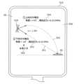
また、例えば、前記第1圧力が算出されたとき、前記噴出口から前記対象物までの第1到達軌跡を表示し、前記第2圧力が算出されたとき、前記噴出口から前記対象物までの第2到達軌跡を表示するディスプレイをさらに備えてもよい。 Further, for example, when the first pressure is calculated, a first reaching trajectory from the ejection port to the object is displayed, and when the second pressure is calculated, the distance from the ejection port to the object is displayed. A display that displays the second reaching trajectory may be further provided.
これにより、浄化剤の到達軌跡を表示するので、ユーザに噴出の様子を模式的に提示することができる。 As a result, the arrival trajectory of the cleaning agent is displayed, so that it is possible to present the user with a schematic view of the jetting state.
また、例えば、前記ディスプレイは、前記第1圧力が算出されたとき、前記第1到達軌跡及び前記第1圧力を表示し、前記第2圧力が算出されたとき、前記第2到達軌跡及び前記第2圧力を表示してもよい。 Further, for example, the display displays the first reaching trajectory and the first pressure when the first pressure is calculated, and displays the second reaching trajectory and the first pressure when the second pressure is calculated. 2 pressure may be displayed.
これにより、ユーザは、表示された圧力を、到達軌跡を選択するための判断材料に利用することができる。つまり、ユーザによる適切な選択を支援することができ、対象物の浄化を効率良く行うことができる。 Thereby, the user can use the displayed pressure as a judgment material for selecting the reaching trajectory. That is, it is possible to assist the user in making an appropriate selection, and to efficiently purify the object.
また、例えば、前記制御部は、前記第1到達軌跡及び前記第2到達軌跡が前記ディスプレイに同時に表示されたとき、前記第1到達軌跡及び前記第2到達軌跡のいずれか一方の選択を受け付け、選択された到達軌跡に対応する圧力で前記噴出口から前記浄化剤を噴出させてもよい。 Further, for example, when the first reaching trajectory and the second reaching trajectory are simultaneously displayed on the display, the control unit accepts selection of one of the first reaching trajectory and the second reaching trajectory, The cleaning agent may be ejected from the ejection port at a pressure corresponding to the selected trajectory.
これにより、ユーザに到達軌跡を選択させることができるので、ユーザ利便性を高めることができる。 As a result, the user can be made to select the arrival trajectory, so that user convenience can be enhanced.
また、例えば、前記ディスプレイは、前記第1到達軌跡の選択を推奨する推奨情報を表示してもよい。 Also, for example, the display may display recommendation information that recommends selection of the first reaching trajectory.
これにより、ユーザによる適切な選択を支援することができ、対象物の浄化を効率良く行うことができる。 As a result, it is possible to assist the user in making an appropriate selection, and to efficiently purify the object.
また、本開示の一態様に係る浄化方法は、第1光を出射する光源、及び、前記第1光が照射された領域からの第2光を受光する受光部を含む光センサから出力された電気信号に基づいて、前記領域内における対象物の有無を判別するステップと、浄化剤を噴出口から噴出するステップと、前記噴出口から前記対象物までの距離を計測するステップと、前記距離に基づいて、前記浄化剤の噴出を制御するステップとを含む。 Further, a purification method according to an aspect of the present disclosure includes a light source that emits a first light, and an optical sensor that includes a light receiving unit that receives a second light from a region irradiated with the first light. determining the presence or absence of an object within the area based on the electric signal; ejecting a cleaning agent from a jetting port; measuring a distance from the jetting port to the target; and controlling the ejection of the cleaning agent based on.
これにより、対象物の有無の判別と対象物の浄化とを行うので、対象物の検出から検出した対象物の浄化までを簡易に行うことができる。また、計測された距離に基づいて浄化剤の噴出が制御されるので、対象物に向けて精度良く浄化剤を噴出することができる。このため、浄化剤と対象物との接触確率を高めることができ、対象物の浄化を効率良く行うことができる。 As a result, determination of the presence or absence of the object and purification of the object are performed, so that detection of the object and purification of the detected object can be easily performed. In addition, since the ejection of the cleaning agent is controlled based on the measured distance, the cleaning agent can be ejected toward the object with high precision. Therefore, the probability of contact between the cleaning agent and the object can be increased, and the object can be cleaned efficiently.
また、例えば、重力方向と垂直な仮想平面に対する前記噴出口の傾きを検出するステップをさらに含み、前記制御するステップでは、計測された距離と前記浄化剤を噴出する圧力との組合せ、及び、計測された距離と前記噴出口の傾きとの組合せのいずれか一方の組合せに応じて、前記浄化剤の噴出の条件を制御してもよい。 Further, for example, the step of detecting the inclination of the ejection port with respect to a virtual plane perpendicular to the direction of gravity is further included, and in the step of controlling, the combination of the measured distance and the pressure at which the cleaning agent is ejected, and the measurement The ejection conditions of the cleaning agent may be controlled according to any one of the combination of the distance and the inclination of the ejection port.
これにより、対象物までの距離だけでなく、噴出の際の圧力又は噴出口の傾きに基づいて噴出の条件が制御されるので、対象物に向けて精度良く浄化剤を噴出することができる。このため、浄化剤と対象物との接触確率を高めることができ、対象物の浄化を効率良く行うことができる。 As a result, the ejection conditions are controlled based on not only the distance to the object but also the pressure at the time of ejection or the inclination of the ejection port, so the cleaning agent can be accurately ejected toward the object. Therefore, the probability of contact between the cleaning agent and the object can be increased, and the object can be cleaned efficiently.
また、例えば、ユーザによる、前記浄化剤が噴出されるときの前記仮想平面に対する前記噴出口の傾きである噴出時の傾きの決定を受け付けるステップをさらに含み、前記制御するステップでは、前記噴出時の傾きとして前記仮想平面より下向きの傾きが決定されたとき、前記浄化剤が前記対象物に到達する第1圧力を算出し、前記第1圧力で前記噴出口から前記浄化剤を噴出させ、前記噴出時の傾きとして前記仮想平面より上向きの傾きが決定されたとき、前記第1圧力より高い第2圧力を算出し、前記第2圧力で前記噴出口から前記浄化剤を噴出させてもよい。 The method may further include, for example, receiving a determination by a user of an inclination at the time of ejection, which is an inclination of the ejection port with respect to the virtual plane when the cleaning agent is ejected, and the step of controlling includes: When a slope downward from the virtual plane is determined as the slope, a first pressure at which the cleaning agent reaches the object is calculated, the cleaning agent is ejected from the ejection port at the first pressure, and the ejection is performed. A second pressure higher than the first pressure may be calculated when the slope upward from the imaginary plane is determined as the time slope, and the cleaning agent may be ejected from the ejection port at the second pressure.
これにより、仮想平面に対して上向き又は下向きで浄化剤を噴出するときの圧力を精度良く算出することができる。このため、対象物に向けて精度良く浄化剤を噴出することができ、対象物の浄化を効率良く行うことができる。 This makes it possible to accurately calculate the pressure when the cleaning agent is jetted upward or downward with respect to the virtual plane. Therefore, the cleaning agent can be jetted toward the object with high accuracy, and the object can be cleaned efficiently.
また、例えば、前記第1圧力が算出されたとき、前記噴出口から前記対象物までの第1到達軌跡をディスプレイに表示させ、前記第2圧力が算出されたとき、前記噴出口から前記対象物までの第2到達軌跡を前記ディスプレイに表示させるステップをさらに含んでもよい。 Further, for example, when the first pressure is calculated, a first reaching trajectory from the jet outlet to the object is displayed on the display, and when the second pressure is calculated, the jet outlet to the object is displayed. The method may further include causing the display to display a second reaching trajectory to .
これにより、浄化剤の到達軌跡を表示するので、ユーザに噴出の様子を模式的に提示することができる。 As a result, the arrival trajectory of the cleaning agent is displayed, so that it is possible to present the user with a schematic view of the jetting state.
また、例えば、前記表示させるステップでは、前記第1圧力が算出されたとき、前記第1到達軌跡及び前記第1圧力を前記ディスプレイに表示させ、前記第2圧力が算出されたとき、前記第2到達軌跡及び前記第2圧力を前記ディスプレイに表示させてもよい。 Further, for example, in the displaying step, when the first pressure is calculated, the first reaching trajectory and the first pressure are displayed on the display, and when the second pressure is calculated, the second The reaching trajectory and the second pressure may be displayed on the display.
これにより、ユーザは、表示された圧力を、到達軌跡を選択するための判断材料に利用することができる。つまり、ユーザによる適切な選択を支援することができ、対象物の浄化を効率良く行うことができる。 Thereby, the user can use the displayed pressure as a judgment material for selecting the reaching trajectory. That is, it is possible to assist the user in making an appropriate selection, and to efficiently purify the object.
また、例えば、前記制御するステップでは、前記第1到達軌跡及び前記第2到達軌跡が前記ディスプレイに同時に表示されたとき、前記第1到達軌跡及び前記第2到達軌跡のいずれか一方の選択を受け付け、選択された到達軌跡に対応する圧力で前記噴出口から前記浄化剤を噴出させてもよい。 Further, for example, in the controlling step, when the first reaching trajectory and the second reaching trajectory are simultaneously displayed on the display, selection of either one of the first reaching trajectory and the second reaching trajectory is accepted. , the cleaning agent may be ejected from the ejection port at a pressure corresponding to the selected trajectory.
これにより、ユーザに到達軌跡を選択させることができるので、ユーザ利便性を高めることができる。 As a result, the user can be made to select the arrival trajectory, so that user convenience can be enhanced.
また、例えば、前記表示させるステップでは、前記第1到達軌跡の選択を推奨する推奨情報を前記ディスプレイに表示させてもよい。 Further, for example, in the displaying step, recommendation information for recommending selection of the first reaching locus may be displayed on the display.
これにより、ユーザによる適切な選択を支援することができ、対象物の浄化を効率良く行うことができる。 As a result, it is possible to assist the user in making an appropriate selection, and to efficiently purify the object.
また、例えば、前記第1光は、前記対象物を励起する励起光であり、前記第2光は、前記励起光が照射された場合に、前記対象物が発する蛍光であってもよい。 Further, for example, the first light may be excitation light that excites the object, and the second light may be fluorescence emitted by the object when the object is irradiated with the excitation light.
これにより、対象物から発せられる蛍光を受光部によって受光することができるので、蛍光の波長及び強度などに基づいて対象物の有無を精度良く判別することができる。したがって、判別の精度が高められることで、対象物の検出漏れを抑制することができ、対象物の浄化を十分に行うことができる。 As a result, the fluorescence emitted from the object can be received by the light-receiving unit, so the presence or absence of the object can be determined with high accuracy based on the wavelength and intensity of the fluorescence. Therefore, by increasing the accuracy of determination, it is possible to suppress detection omissions of the target object, and to sufficiently purify the target object.
また、例えば、前記判別するステップでは、前記蛍光の波長と前記励起光の波長との組み合わせに基づいて前記対象物の有無を判別してもよい。 Further, for example, in the determining step, the presence or absence of the object may be determined based on a combination of the wavelength of the fluorescence and the wavelength of the excitation light.
これにより、検出目的の対象物に応じた組み合わせで光センサを構成した場合に、対象物の検出精度をより高めることができる。 As a result, the detection accuracy of the object can be further improved when the optical sensor is configured with a combination according to the object to be detected.
また、例えば、前記判別するステップでは、前記第2光の受光強度と閾値との比較結果に基づいて前記対象物の有無を判別してもよい。 Further, for example, in the determining step, the presence or absence of the object may be determined based on a comparison result between the received light intensity of the second light and a threshold value.
これにより、比較処理によって対象物の有無を判別することができるので、判別処理に要する処理量を削減することができる。 As a result, the presence or absence of the object can be determined by the comparison processing, so the amount of processing required for the determination processing can be reduced.
また、例えば、前記判別するステップでは、前記第2光のうち、前記第1光の波長よりも波長が長い成分に基づいて前記対象物の有無を判別してもよい。 Further, for example, in the determining step, the presence or absence of the object may be determined based on a component of the second light having a wavelength longer than that of the first light.
これにより、照射した第1光とは異なる波長成分に基づいて対象物の有無を判別するので、第1光の反射光などの影響を抑制することができ、対象物の検出精度を高めることができる。 As a result, the presence or absence of the object is determined based on the wavelength component different from that of the irradiated first light, so that the influence of the reflected light of the first light can be suppressed, and the detection accuracy of the object can be improved. can.
本開示において、回路、ユニット、装置、部材又は部の全部又は一部、又はブロック図の機能ブロックの全部又は一部は、半導体装置、半導体集積回路(IC)、又はLSI(large scale integration)を含む一つ又は複数の電子回路によって実行されてもよい。LSI又はICは、一つのチップに集積されてもよいし、複数のチップを組み合わせて構成されてもよい。例えば、記憶素子以外の機能ブロックは、一つのチップに集積されてもよい。ここでは、LSIまたはICと呼んでいるが、集積の度合いによって呼び方が変わり、システムLSI、VLSI(very large scale integration)、若しくはULSI(ultra large scale integration)と呼ばれるものであってもよい。LSIの製造後にプログラムされる、Field Programmable Gate Array(FPGA)、又はLSI内部の接合関係の再構成又はLSI内部の回路区画のセットアップができるreconfigurable logic deviceも同じ目的で使うことができる。 In the present disclosure, all or part of circuits, units, devices, members or parts, or all or part of functional blocks in block diagrams are semiconductor devices, semiconductor integrated circuits (ICs), or LSIs (large scale integration). may be performed by one or more electronic circuits comprising: An LSI or IC may be integrated on one chip, or may be configured by combining a plurality of chips. For example, functional blocks other than memory elements may be integrated on one chip. Although they are called LSIs or ICs here, they may be called system LSIs, VLSIs (very large scale integration), or ULSIs (ultra large scale integration) depending on the degree of integration. A Field Programmable Gate Array (FPGA), which is programmed after the LSI is manufactured, or a reconfigurable logic device capable of reconfiguring connection relationships inside the LSI or setting up circuit partitions inside the LSI can also be used for the same purpose.
さらに、回路、ユニット、装置、部材又は部の全部又は一部の機能又は操作は、ソフトウェア処理によって実行することが可能である。この場合、ソフトウェアは一つ又は複数のROM、光学ディスク、ハードディスクドライブなどの非一時的記録媒体に記録され、ソフトウェアが処理装置(processor)によって実行されたときに、そのソフトウェアで特定された機能が処理装置(processor)および周辺装置によって実行される。システム又は装置は、ソフトウェアが記録されている一つ又は複数の非一時的記録媒体、処理装置(processor)、及び必要とされるハードウェアデバイス、例えばインタフェース、を備えていても良い。 Furthermore, all or part of the functions or operations of circuits, units, devices, members or parts can be performed by software processing. In this case, the software is recorded on one or more non-transitory storage media such as ROMs, optical discs, hard disk drives, etc., and when the software is executed by a processor, the functions specified in the software are performed. It is executed by processors and peripherals. A system or apparatus may comprise one or more non-transitory storage media on which software is recorded, a processor, and required hardware devices such as interfaces.
以下では、本開示の実施の形態について、図面を参照しながら具体的に説明する。 Embodiments of the present disclosure will be specifically described below with reference to the drawings.
なお、以下で説明する実施の形態は、いずれも包括的又は具体的な例を示すものである。以下の実施の形態で示される数値、形状、材料、構成要素、構成要素の配置位置及び接続形態、ステップ、ステップの順序などは、一例であり、本開示を限定する主旨ではない。また、以下の実施の形態における構成要素のうち、独立請求項に記載されていない構成要素については、任意の構成要素として説明される。 It should be noted that the embodiments described below are all comprehensive or specific examples. Numerical values, shapes, materials, components, arrangement positions and connection forms of components, steps, order of steps, and the like shown in the following embodiments are examples, and are not intended to limit the present disclosure. Further, among the constituent elements in the following embodiments, constituent elements not described in independent claims will be described as optional constituent elements.
また、各図は、模式図であり、必ずしも厳密に図示されたものではない。したがって、例えば、各図において縮尺などは必ずしも一致しない。また、各図において、実質的に同一の構成については同一の符号を付しており、重複する説明は省略又は簡略化する。 Each figure is a schematic diagram and is not necessarily strictly illustrated. Therefore, for example, scales and the like do not necessarily match in each drawing. Moreover, in each figure, the same code|symbol is attached|subjected about the substantially same structure, and the overlapping description is abbreviate|omitted or simplified.
(実施の形態1)
[1.構成]
まず、実施の形態1に係る浄化装置の概要について、図1から図3を用いて説明する。(Embodiment 1)
[1. composition]
First, the outline of the purifier according to
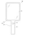
図1及び図2はそれぞれ、本実施の形態に係る浄化装置10の正面図及び背面図である。図3は、本実施の形態に係る浄化装置10の構成を示すブロック図である。 1 and 2 are respectively a front view and a rear view of a
なお、本実施の形態において、浄化装置10の正面は、ディスプレイ50の表示面が設けられている側である。浄化装置10の背面は、正面の反対側である。本実施の形態では、図2に示すように、浄化装置10の背面側に、光センサ30及び噴出部60の噴出口62などが設けられている。 In addition, in the present embodiment, the front of the
浄化装置10は、対象物の検出から検出した対象物の浄化までを一体的に行う装置である。本実施の形態では、浄化装置10は、対象物の検出及び浄化を非接触で行う。具体的には、浄化装置10は、浄化装置10から離れた領域内の対象物を光学的に検出し、かつ、検出した対象物に向けて浄化剤を噴出することで、対象物の浄化を行う。 The
対象物は、例えば、嘔吐物、排泄物又は体液などの人が排出したものである。あるいは、対象物は、食材又は食品などでもよい。対象物は、ウイルス又は細菌などの、人の病気を引き起こしうる微生物などを含んでいる。本実施の形態では、対象物は、有機物を含んでおり、所定の波長の励起光が照射された場合に蛍光を発する。例えば有機物は、食品又は生物などに多く含まれるアミノ酸などであるが、これに限らない。アミノ酸は、例えば、280nm近傍の励起光が照射された場合に、320nm近傍の蛍光を発する。 Objects are, for example, human excretions such as vomit, faeces or bodily fluids. Alternatively, the target object may be food, food, or the like. Objects include microorganisms, such as viruses or bacteria, that can cause disease in humans. In this embodiment, the target includes an organic substance, and emits fluorescence when it is irradiated with excitation light of a predetermined wavelength. For example, organic substances are amino acids that are abundantly contained in foods or living organisms, but are not limited to these. Amino acids, for example, emit fluorescence near 320 nm when irradiated with excitation light near 280 nm.
浄化剤は、対象物を浄化するための薬剤などである。対象物の浄化とは、例えば、対象物に含まれるウイルス又は細菌などの微生物を分解し、無害化することである。浄化剤は、例えば、次亜塩素酸ナトリウム製剤又はアルコール製剤などである。浄化剤は、例えば液体であるが、気体又は固体でもよい。 A purifying agent is, for example, a chemical agent for purifying an object. Purification of an object means, for example, decomposing microorganisms such as viruses or bacteria contained in the object to render it harmless. The cleaning agent is, for example, a sodium hypochlorite preparation or an alcohol preparation. The cleaning agent is for example liquid, but it can also be gaseous or solid.
図1から図3に示すように、浄化装置10は、筐体20と、光センサ30と、判別回路40と、ディスプレイ50と、噴出部60と、操作ボタン70と、測距部80とを備える。以下では、浄化装置10を構成する各構成要素について、詳細に説明する。 As shown in FIGS. 1 to 3, the
筐体20は、浄化装置10の外殻をなしている。図1及び図2に示すように、筐体20は、枠体部21と、持手部22とを備える。 The
枠体部21は、主にディスプレイ50を保持する部分であり、扁平なトレイ状に構成されている。図1に示すように、枠体部21の正面側には、ディスプレイ50の表示面が露出している。図2に示すように、枠体部21の背面側には、光センサ30、噴出部60の噴出口62、及び、測距部80が露出している。なお、光センサ30、噴出口62及び測距部80の配置は、図示した例に限らない。 The
持手部22は、人が片手又は両手で把持するための部分である。図1及び図2に示すように、持手部22は、枠体部21の一部から一方向に延びるように設けられた棒状の部分である。持手部22の形状は、円柱状又は角柱状であるが、これに限らない。 The
本実施の形態では、図1に示すように、持手部22には、噴出部60の操作ボタン70が設けられている。操作ボタン70は、例えば、持手部22の正面側に設けられている。持手部22を片手で持った場合に、親指で操作可能な範囲に設けられている。 In this embodiment, as shown in FIG. 1, the
図2に示すように、光センサ30は、光源31及び受光部32を有する。光センサ30は、受光部32によって生成された電気信号を、判別回路40の信号処理回路41に出力する。 As shown in FIG. 2 , the
光源31は、対象物を励起する励起光を発する。なお、励起光は、光源31が発する第1光の一例である。励起光は、例えば、検出目的の対象物の種類に応じて予め選択された波長にピークを有する光である。励起光のピークの半値幅は、例えば10nm以上50nm以下の範囲である。 The
本実施の形態では、光源31は、波長が互いに異なる複数の励起光を第1光として発する。具体的には、光源31は、複数の励起光を時間排他的に発する。例えば、光源31は、280nm、350nm及び450nmの各々の波長を有する複数の励起光を順次出射する。なお、これらの励起波長は一例に過ぎず、例えば、対象物の種類などに応じて任意の波長から適宜選択されてもよい。 In the present embodiment, the
例えば、光源31は、波長を時間連続的に変化させながら励起光を対象物に照射してもよい。例えば、光源31は、220nm以上550nm以下の範囲において10nm刻みで波長を変化させながら、互いに波長が異なる複数の励起光を順次対象物に照射してもよい。 For example, the
あるいは、光源31の光出射側には、透過帯域が異なる複数のフィルタが設けられていてもよい。複数のフィルタのうち光源31から発せられた光が通過するフィルタを順次変更することで、互いに波長が異なる複数の励起光を順次対象物に照射することができる。 Alternatively, a plurality of filters with different transmission bands may be provided on the light exit side of the
光源31は、例えば、ハロゲンランプなどの放電ランプ、又は、LED(Light Emitting Diode)などの固体発光素子であるが、これに限らない。 The
受光部32は、光源31が発する第1光が照射された照射領域からの第2光を受光する。例えば、光源31が発する第1光による照射領域と、受光部32による受光領域(すなわち、撮影範囲)とは、重複又は一致している。 The
受光部32は、具体的には、複数の画素が二次元状に配列されたイメージセンサである。複数の画素の各々には、受光した光を光電変換するフォトダイオードなどの光電変換素子が含まれる。受光部32の各画素から出力される電気信号を処理することで、撮影画像が生成される。 Specifically, the
本実施の形態では、受光部32は、入射する光を波長選択的に第2光として受光する。具体的には、受光部32は、受光の対象とする第2光の波長(すなわち、観測波長)を変化させながら、観測波長毎の受光強度を表す電気信号を生成して出力する。 In this embodiment, the
例えば、受光部32は、光電変換素子の光入射側に配置された複数のフィルタであって、透過帯域が互いに異なる複数のフィルタを有する。フィルタの透過帯域が、受光部32による観測波長に相当する。受光部32は、複数のフィルタを時間排他的に切り替えることで、異なる波長の光を受光する。例えば、受光部32は、310nm、425nm及び520nmの各々の波長を有する複数の光を順次受光する。なお、これらの観測波長は一例に過ぎず、例えば、対象物の種類などに応じて任意の波長から適宜選択されてもよい。 For example, the
判別回路40は、照射領域内における対象物の有無を判別し、判別結果を示す画像を生成する。判別回路40は、例えば、プログラムが格納された不揮発性メモリ、プログラムを実行するための一時的な記録領域である揮発性メモリ、入出力ポート、プログラムを実行するプロセッサなどで実現される。 A
図3に示すように、判別回路40は、光センサ30から出力された電気信号を処理する信号処理回路41を有する。信号処理回路41は、1以上の電子回路を含む集積回路などで実現される。 As shown in FIG. 3 , the
判別回路40は、蛍光の波長と励起光の波長との組み合わせに基づいて対象物の有無を判別する。具体的には、判別回路40は、受光部32の画素毎に対象物の有無を判別する。これにより、判別回路40は、撮影画像内のどの画素に、すなわち、撮影範囲内のどの位置に対象物が存在するか、及び、対象物が存在する場合にその大きさ及び形状などを判別することができる。 The
本実施の形態では、判別回路40は、画素毎に、蛍光指紋を利用した判別処理を行う。蛍光指紋を利用した判別処理の詳細については、後で説明する。 In the present embodiment, the
ディスプレイ50は、判別回路40によって生成された画像を表示する。また、ディスプレイ50は、受光部32によって生成された撮影画像を表示する。ディスプレイ50は、例えば液晶表示装置又は有機EL(Electro Luminescence)表示装置などのフラットパネルディスプレイである。 A
噴出部60は、対象物を浄化するための浄化剤が入れられる容器61、及び、浄化剤を噴出するための噴出口62を有し、判別結果に基づいて浄化剤を噴出口62から噴出する。例えば、噴出部60は、霧状の浄化剤を噴出口62から噴霧する。噴出部60は、図示しない制御回路などを備える。制御回路は、1以上の電子回路を含む集積回路などで実現され、浄化剤の噴出のタイミング及び噴出の態様などを制御する。 The
容器61は、持手部22の内部に設けられている。容器61は、持手部22に対して着脱自在である。例えば、容器61は、浄化剤が予め容れられたカートリッジ式の容器である。具体的には、持手部22は、筒状に構成されており、端部から容器61が挿入される。容器61が所定位置まで挿入されることで、容器61と噴出口62とが接続されて、容器61内の浄化剤が噴出口62を介して噴出可能な状態に取り付けられる。例えば、容器61が持手部22に挿入された状態で、操作ボタン70をユーザが操作した場合に、噴出口62から浄化剤が噴出される。 The
本実施の形態では、噴出部60は、測距部80によって計測された距離に応じて浄化剤の噴出の態様を制御する。浄化剤の噴出の態様は、具体的には、浄化剤を噴出する圧力である。噴出部60は、測距部80によって計測された距離に基づいて、浄化剤を噴出する圧力を変更する。 In the present embodiment, the
例えば、噴出部60は、対象物までの距離が長い程、強い圧力で浄化剤を噴出する。これにより、遠くに位置する対象物に対して浄化剤を接触させ、対象物の浄化を行うことができる。また、噴出部60は、対象物までの距離が短い場合には、弱い圧力で浄化剤を噴出する。 For example, the
なお、噴出の態様には、浄化剤の噴出量、噴出方向、噴出口62の開口幅などが含まれてもよい。例えば、噴出部60は、対象物が存在する範囲が大きい場合に、噴出口62の開口幅を大きくして広範囲で浄化剤を噴出してもよい。このとき、噴出部60は、浄化剤の噴出量を多くしてもよい。また、噴出部60は、対象物が存在する範囲が狭い場合に、噴出口62の開口幅を小さくして狭い範囲に浄化剤を噴出してもよい。このとき、噴出部60は、浄化剤の噴出量を少なくしてもよい。 The mode of ejection may include the ejection amount of the cleaning agent, the ejection direction, the opening width of the
操作ボタン70は、光源31の発光及び浄化剤の噴出の少なくとも一方を行わせるためのトリガとなる物理的なボタンである。例えば、操作ボタン70が1回押されることで、光源31から励起光が発せられ、対象物の判別処理が行われる。その後、再び操作ボタン70が1回押されることで、噴出口62から浄化剤が噴出される。あるいは、操作ボタン70の1回の押下が光源31の発光のトリガであってもよく、操作ボタン70の長押しが浄化剤の噴出のトリガであってもよい。 The
なお、操作ボタン70は、ディスプレイ50と一体化されていてもよい。具体的には、ディスプレイ50は、タッチパネルディスプレイでもよく、光源31の発光及び浄化剤の噴出の少なくとも一方を行わせるためのGUI(Graphical User Interface)オブジェクトなどを表示してもよい。ユーザは、ディスプレイ50に表示されたGUIオブジェクトをタッチすることで、光源31の発光及び浄化剤の噴出の少なくとも一方を行わせてもよい。 Note that the
測距部80は、対象物までの距離を計測する。測距部80は、例えばToF(Time of Flight)方式で、対象物までの距離を計測する。具体的には、測距部80は、光を出射する光源と、出射した光の対象物による反射光を受光する受光部とを備え、出射した光が対象物で反射して受光部によって受光されるまでの時間を計測することで、対象物までの距離を計測する。測距部80は、位相差距離方式及びパルス伝播方式のいずれを用いてもよい。 A
なお、測距部80の光源及び受光部の少なくとも一方は、光センサ30の光源31及び受光部32の少なくとも一方と兼用されてもよい。あるいは、測距部80は、超音波センサ又は赤外線センサであってもよい。また、測距部80は、ステレオカメラ方式で、対象物までの距離を計測してもよい。 At least one of the light source and the light receiving section of the
[2.蛍光指紋を利用した判別処理]
ここで、判別回路40が行う、蛍光指紋を利用した判別処理について説明する。[2. Discrimination processing using fluorescent fingerprint]
Here, the discrimination processing using fluorescent fingerprints performed by the
蛍光指紋とは、励起蛍光マトリクス(Excitation Emission Matrix:EEM)情報である。蛍光指紋は、励起波長と、蛍光波長と、蛍光強度とを三軸とする三次元データである。励起波長は、対象物に照射する励起光の波長である。蛍光波長は、対象物から発せられる蛍光の波長である。蛍光指紋は、例えば、対象物に照射する励起光の波長を連続的に変化させながら蛍光スペクトルを測定することによって得られる。 A fluorescence fingerprint is excitation emission matrix (EEM) information. A fluorescence fingerprint is three-dimensional data with three axes of excitation wavelength, fluorescence wavelength, and fluorescence intensity. The excitation wavelength is the wavelength of the excitation light with which the object is irradiated. A fluorescence wavelength is a wavelength of fluorescence emitted from an object. A fluorescence fingerprint is obtained, for example, by measuring a fluorescence spectrum while continuously changing the wavelength of excitation light with which an object is irradiated.
蛍光指紋は、対象物の種類毎に決まっている。つまり、蛍光強度が大きくなる励起波長と蛍光波長との組み合わせは、対象物の種類毎に決まっている。例えば、食品又は生物の主な成分であるたんぱく質を構成するアミノ酸類では、280nm近傍にピークを有する励起光を照射した場合、320nm近傍にピークを有する蛍光を発する。 A fluorescent fingerprint is determined for each type of object. That is, the combination of the excitation wavelength and the fluorescence wavelength that increases the fluorescence intensity is determined for each type of object. For example, amino acids that constitute proteins, which are the main components of food or living organisms, emit fluorescence with a peak near 320 nm when irradiated with excitation light that has a peak near 280 nm.
このため、例えば、本実施の形態では、光源31は、例えば280nm近傍にピークを有する励起光を第1光として発する。受光部32は、例えば320nm近傍を観測波長として光を受光する。これにより、光センサ30から出力された電気信号の信号強度は、蛍光強度の大きさを表すことになる。したがって、判別回路40は、電気信号の信号強度に基づいて、アミノ酸の有無を判別することができる。 For this reason, for example, in the present embodiment, the
励起波長と観測波長との複数の組み合わせで、励起光の出射と受光部32による受光とを行うことで、組み合わせ毎の受光強度が得られる。これにより、信号処理回路41は、蛍光指紋を生成することができる。 By performing excitation light emission and light reception by the
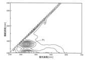
図4は、本実施の形態に係る浄化装置10によって取得された、対象物が存在する画素における蛍光指紋を示す図である。図4では、縦軸を励起波長とし、横軸を蛍光波長とする二次元座標系において、蛍光強度が等しい座標を連続的に結ぶ等強度線を図示している。 FIG. 4 is a diagram showing fluorescence fingerprints in pixels where an object exists, acquired by the
ここでは、対象物として嘔吐物などの代わりにヨーグルトを付着させた便器タイルを用いている。例えば、光源31は、励起光として波長を時間連続的に変化させながら励起光を照射し、受光部32は、フィルタなどを利用して観測波長を時間連続的に変化させながら光を受光する。これにより、励起波長と蛍光波長との組み合わせ毎に、当該組み合わせに対応する蛍光強度を示す電気信号が得られる。信号処理回路41が、受光部32から出力される電気信号を処理することで、図4に示す蛍光指紋が得られる。 Here, instead of objects such as vomit, toilet bowl tiles to which yoghurt is adhered are used. For example, the
図4に示すように、励起波長が280nm近傍で、かつ、蛍光波長が320nm近傍の位置にピークP1が現れていることが分かる。したがって、ヨーグルトに含まれるアミノ酸から発せられた蛍光が検出されたことが分かる。 As shown in FIG. 4, it can be seen that a peak P1 appears at a position near the excitation wavelength of 280 nm and the fluorescence wavelength of near 320 nm. Therefore, it can be seen that the fluorescence emitted from the amino acids contained in the yogurt was detected.
なお、本実施の形態では、判別回路40が対象物の有無を判別するため、対象物が存在しない場合に受光部32によって受光される光についても考慮する。具体的には、対象物が存在しない場合、受光部32による撮影範囲に入る床面などからの反射光又は蛍光が受光部32によって受光される。例えば、図4と同様に、ヨーグルトを付着させた便器タイルの場合、便器タイルからの蛍光も起こりうる。 In this embodiment, since the
図5は、本実施の形態に係る浄化装置10によって取得された、対象物が存在しない画素における蛍光指紋を示す図である。図5では、図4と同様に、縦軸を励起波長とし、横軸を蛍光波長とする二次元座標系において、蛍光強度が等しい座標を連続的に結ぶ等強度線を図示している。 FIG. 5 is a diagram showing fluorescence fingerprints in pixels where there is no object, acquired by the
図5は、具体的には、便器タイルの蛍光指紋を示している。便器タイルの蛍光指紋の生成方法は、図4で示した蛍光指紋を生成する場合と同じである。 FIG. 5 specifically shows a fluorescent fingerprint of a toilet bowl tile. The method of generating fluorescent fingerprints of toilet bowl tiles is the same as for generating the fluorescent fingerprints shown in FIG.
図5に示すように、励起波長が220nm近傍で、かつ、蛍光波長が480nm近傍の位置にピークP2が現れていることが分かる。図4と図5とを比較して分かるように、便器タイルとヨーグルトに含まれるアミノ酸とでは、蛍光強度が大きくなる励起波長と蛍光波長との組み合わせが相違している。このため、便器タイルによる蛍光に影響を受けずに、アミノ酸の有無を検出することが可能となる。 As shown in FIG. 5, it can be seen that a peak P2 appears at a position where the excitation wavelength is around 220 nm and the fluorescence wavelength is around 480 nm. As can be seen by comparing FIG. 4 and FIG. 5, the combination of the excitation wavelength and the fluorescence wavelength at which the fluorescence intensity increases differs between the toilet bowl tile and the amino acid contained in the yogurt. Therefore, it is possible to detect the presence or absence of amino acids without being affected by fluorescence from toilet tiles.
また、一方で、便器タイルの表面に何も付着していない場合にはピークP2が現れるので、ピークP2が観測されないときには、便器タイルの表面にアミノ酸以外の対象物が付着していると判別することが可能となる。これにより、検出目的とするアミノ酸以外の物質の有無の判別も可能となる。 On the other hand, when nothing adheres to the surface of the toilet bowl tile, the peak P2 appears. Therefore, when the peak P2 is not observed, it is determined that an object other than amino acids adheres to the surface of the toilet bowl tile. becomes possible. This makes it possible to determine the presence or absence of substances other than amino acids to be detected.
[3.動作]
続いて、本実施の形態に係る浄化装置10の動作について説明する。[3. motion]
Next, the operation of the
図6は、本実施の形態に係る浄化装置10の使用例を示す図である。図7は、本実施の形態に係る浄化装置10の動作を示すフローチャートである。 FIG. 6 is a diagram showing a usage example of the
本実施の形態では、図6に示すように、浄化装置10は、ユーザの片手90で持手部22が保持されることで、ユーザの意図に応じて対象領域91を自在に変更可能である。ユーザは、例えば嘔吐物の清掃処理を行った後、浄化装置10を用いて、嘔吐物の清掃跡92を含む範囲を対象領域91として、清掃しきれなかった嘔吐物である対象物93が存在するか否かを検査する。対象領域91は、受光部32による受光領域(すなわち、撮影範囲)に相当する。例えば、ディスプレイ50には、受光部32によって撮影された撮影画像が表示される。 In the present embodiment, as shown in FIG. 6, the
ユーザは、浄化装置10のディスプレイ50に表示される範囲、すなわち、受光部32による撮影範囲に清掃跡92が含まれるように、浄化装置10の姿勢を調整し、操作ボタン70を押下する。操作ボタン70の押下によって浄化装置10の動作が開始される。 The user adjusts the posture of the
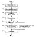
操作ボタン70が押下されることで、図7に示すように、まず、光源31が励起光を第1光として対象領域91に照射する(S10)。受光部32は、光源31からの第1光が照射された状態の対象領域91からの第2光を受光する(S11)。 When the
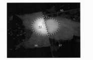
ここで、図8は、本実施の形態に係る浄化装置10によって取得された原画像を示す図である。図8では、励起光が照射されている領域95を破線で囲んでいる。領域95には、便器タイルが存在している。さらに、破線で囲んだ領域95のうち、左側の領域96には対象物93としてヨーグルトが付着されており、右側の領域97には何も付着していない。 Here, FIG. 8 is a diagram showing an original image acquired by the
図8に示すように、左側の領域96からは蛍光に基づく強い光が受光され、右側の領域97からは励起光の反射光などに基づく弱い光が受光されている。 As shown in FIG. 8, the
次に、図7に示すように、判別回路40は、対象領域91内の対象物93の有無を判別する(S12)。本実施の形態では、第1光として対象物93を励起する励起光が照射されるので、対象領域91に対象物93が含まれている場合、受光部32によって受光される第2光には、対象物93からの蛍光が含まれる。したがって、判別回路40は、対象物93からの蛍光が検出された画素には、対象物93が存在すると判定することができる。判別回路40は、画素毎に対象物93の有無を判別する。 Next, as shown in FIG. 7, the
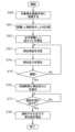
ここで、図9は、本実施の形態に係る浄化装置10の判別回路40が行う判別処理の一例を示すフローチャートである。図9に示すように、判別回路40では、まず、1つの画素を選択する(S20)。次に、判別回路40は、選択した画素から出力された電気信号に基づいて蛍光指紋を生成する(S21)。次に、判別回路40は、生成した蛍光指紋から、背景成分の蛍光指紋を除去する(S22)。例えば、判別回路40は、生成した蛍光指紋から背景成分の蛍光指紋を減算する。背景成分の蛍光指紋は、具体的には、撮影範囲に含まれる床材などの蛍光指紋であって、対象物93が存在しないことが明らかである場合に予め生成されたものである。 Here, FIG. 9 is a flowchart showing an example of determination processing performed by the
次に、判別回路40は、減算後の蛍光指紋に基づいて、選択した画素における対象物93の有無を判別する(S23)。例えば、判別回路40は、アミノ酸に相当する組み合わせ、具体的には、励起波長が280nm近傍及び蛍光波長が320nm近傍の組み合わせの蛍光強度が所定の閾値以上であるかを判定する。当該組み合わせの蛍光強度が閾値以上である場合に、判別回路40は、対象物93が存在すると判定する。当該組み合わせの蛍光強度が閾値より小さい場合に、判別回路40は、対象物93が存在しないと判定する。 Next, the
対象物93が存在する場合(S23でYes)、判別回路40は、選択した画素の画素値を第1値に設定する(S24)。第1値は、例えば、画素値の最大値である。対象物93が存在しない場合(S23でNo)、判別回路40は、選択した画素の画素値を第2値に設定する(S25)。第2値は、第1値とは異なる値であり、例えば、画素値の最小値である。 If the
以降、全ての画素の処理が終了するまで(S26でNo)、ステップS20からS25が繰り返される。これにより、判別回路40は、対象物93の有無に応じて撮影画像を二値化することができる。 Thereafter, steps S20 to S25 are repeated until the processing of all pixels is completed (No in S26). Thereby, the
判別処理を行うことで、図8において、左側の領域96には対象物93が存在し、右側の領域97には対象物93が存在しないことが判別される。なお、判別処理を行うにあたって、情報の圧縮が行われてもよい。蛍光指紋は、三次元データであるため、情報量が多く、処理に要する時間が長くなる恐れがある。このため、判別回路40は、例えば、画素の間引き処理などを行うことで、処理量を低減し、判別処理に要する時間を削減してもよい。つまり、図9に示すステップS26において、全ての画素で処理を行わなくてもよい。 By performing the determination process, it is determined that the
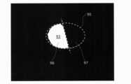
図10は、本実施の形態に係る浄化装置10によって生成された判別結果を表す画像を示す図である。例えば、信号処理回路41は、対象物93が存在すると判別された画素と、対象物93が存在しない画素とを二値で表すことで、図10に示す画像が生成される。図7に示すように、判別処理(S12)の終了後、ディスプレイ50は、判別結果として、図10に示す画像を表示する(S13)。 FIG. 10 is a diagram showing an image representing the determination result generated by the
なお、図10に示す画像は、可視光に基づいて生成された画像に重畳して表示してもよい。これにより、現実の空間における対象物93の位置を分かりやすく表示することができる。 Note that the image shown in FIG. 10 may be superimposed and displayed on the image generated based on visible light. Thereby, the position of the
次に、測距部80は、検出された対象物93までの距離を算出する(S14)。具体的には、測距部80は、対象物93に向けて赤外光を照射し、当該赤外光の反射光を受光することで、照射してから受光するまでの時間に基づいて距離を算出する。 Next, the
次に、噴出部60は、算出された距離に基づいて浄化剤の噴出の圧力を調整する(S15)。具体的には、噴出部60は、算出された距離が長い程、圧力を強くし、算出された距離が短い程、圧力を弱くする。また、このとき、噴出部60は、検出された対象物93の位置に基づいて、浄化剤を噴出する方向を調整してもよい。例えば、図10に示すように、画像内の左側の領域に対象物93が検出された場合には、噴出方向を左側に向けてもよい。 Next, the
最後に、噴出部60は、容器61に貯められた浄化剤を、噴出口62から所定の圧力で噴出する(S16)。これにより、噴出された浄化剤が、検出された対象物93に接触し、対象物93を分解することで無害化させることができる。 Finally, the
なお、距離の算出(S14)及び圧力の調整(S15)は、画像の表示(S13)より先に行われてもよい。 Note that the calculation of the distance (S14) and the adjustment of the pressure (S15) may be performed prior to the display of the image (S13).
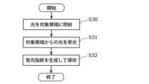
また、本実施の形態では、判別の精度を高めるために、対象物93が存在していないことが明らかである場合に、予め蛍光指紋を取得しておく。図11は、本実施の形態に係る浄化装置10の前処理を示すフローチャートである。 Further, in the present embodiment, in order to increase the accuracy of determination, a fluorescence fingerprint is obtained in advance when it is clear that the
例えば、操作ボタン70が押下された場合に、光源31が励起光を第1光として対象領域91に照射する(S30)。受光部32は、光源31からの第1光が照射された状態の対象領域91からの第2光を受光する(S31)。 For example, when the
判別回路40は、励起波長と蛍光波長との組み合わせ毎の蛍光強度を、対象物93が存在しない場合の蛍光指紋として生成し、生成した蛍光指紋を背景成分の蛍光指紋としてメモリなどに保存する(S32)。 The
メモリなどに保存された背景成分の蛍光指紋は、判別処理(S12及び図7)において参照情報として利用される。これにより、便器タイル又は床材などの背景成分の影響を抑制することができ、対象物93の検出精度を高めることができる。 The fluorescence fingerprint of the background component stored in memory or the like is used as reference information in the discrimination process (S12 and FIG. 7). As a result, the influence of background components such as toilet bowl tiles or floor materials can be suppressed, and the detection accuracy of the
[4.まとめ]
以上のように、本実施の形態に係る浄化装置10は、光センサ30、判別回路40、ディスプレイ50、噴出部60、操作ボタン70及び測距部80が、筐体20内に収納又は筐体20によって保持されている。このように、浄化装置10は、1つの筐体20によって一体化されているので、対象物93の検出から浄化までを簡易に行うことができる。また、筐体20が持手部22を有するので、浄化装置10を容易に持ち運ぶことができる。これにより、様々な場所での対象物93の有無の判別が可能となる。[4. summary]
As described above, in the
[変形例]
以下では、上記の実施の形態1の変形例について説明する。なお、以下の変形例では、実施の形態1との相違点を中心に説明し、共通点の説明を省略又は簡略化する。[Modification]
Below, the modification of said
[変形例1]
まず、判別処理の変形例について説明する。実施の形態1では、蛍光指紋を利用して対象物の有無の判別を行う例を説明した。これに対して、本変形例では、受光強度と閾値との比較に基づいて対象物の判別を行う。[Modification 1]
First, a modification of the determination process will be described. In the first embodiment, the example of determining the presence/absence of an object using fluorescent fingerprints has been described. On the other hand, in this modified example, the object is determined based on the comparison between the received light intensity and the threshold value.
例えば、図8で示す撮影画像のように、対象物93を含む領域95に励起光が照射された場合、対象物93からは蛍光が発せられるのに対して、対象物93が存在しない領域97からは蛍光は発せられない。このため、受光部32の複数の画素のうち、対象物93が存在する画素では蛍光を含む強い第2光が受光されるのに対して、対象物93が存在しない画素では蛍光を含まない第2光が受光される。つまり、対象物93の有無によって、画素毎に受光した光の強度差が生じる。 For example, as in the photographed image shown in FIG. 8, when a
そこで、本変形例に係る判別回路40は、第2光の受光強度と所定の閾値との比較結果に基づいて対象物93の有無を判別する。第2光の受光強度は、撮影画像の画素値で表される。閾値は、対象物93が存在していないことが明らかである場合に予め取得した受光強度などに基づいて定められる。 Therefore, the
具体的には、判別回路40は、対象物93が存在しない場合に励起光が照射された領域95からの光の受光強度を閾値として決定する。例えば、領域97の受光強度の平均値が閾値となる。 Specifically, the
あるいは、閾値は、領域97の受光強度の平均値より小さくてもよい。この場合、対象物93が存在しない画素に対しても、対象物93が存在すると誤って判別する可能性が起こりうる。しかしながら、対象物93が存在する画素を略確実に判別することができるので、対象物93を浄化する目的としては十分である。 Alternatively, the threshold may be smaller than the average value of the received light intensity of the
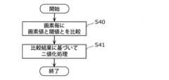
本変形例に係る浄化装置10の動作は、判別処理(図7のS12)が異なる点を除いて、実施の形態1と同じである。図12は、本変形例に係る浄化装置10が行う判別処理の一例を示すフローチャートである。 The operation of the
図12に示すように、本変形例に係る判別回路40は、画素毎に、画素値と閾値とを比較する(S40)。判別回路40は、比較結果に基づいて撮影画像の二値化処理を行う(S41)。具体的には、画素値が閾値以上である場合に、画素値を第1値に設定し、画素値が閾値より小さい場合に、画素値を第2値に設定する。二値化処理(S41)は、図9で示したステップS24及びS25と同じである。 As shown in FIG. 12, the
図13は、本変形例に係る浄化装置10によって生成された判別結果を表す画像を示す図である。図13は、閾値が領域97の受光強度の平均値より小さい値とした場合を示している。例えば、信号処理回路41は、図8に示す撮影画像を閾値に基づいて二値化することで、図13に示す画像を生成する。 FIG. 13 is a diagram showing an image representing the discrimination result generated by the
図13に示すように、本来ならば対象物93が存在しない領域97においても、白色の画素が含まれており、対象物93が存在すると判別されたことが分かる。一方で、領域96も対象物93が存在していると判別されている。 As shown in FIG. 13, white pixels are included even in a
この場合、噴出部60は、領域96だけでなく、領域97にも浄化剤を噴出する。領域97に噴出された浄化剤は対象物93が存在しないため、特に活用されることはないだけで、領域96に噴出された浄化剤によって対象物93を浄化することができる。 In this case, the
以上のように、本変形例に係る浄化装置10によれば、撮影画像を二値化することにより、対象物93の有無を判別することができるので、判別に要する処理量及び時間を削減することができる。 As described above, according to the
なお、本変形例では、蛍光指紋を生成する必要がないので、光源31は、1つの励起光を第1光として発すればよい。受光部32も同様に、1つの波長に対応した受光帯域又は全帯域に亘って第2光を受光すればよい。このため、判別回路40の構成だけでなく、光センサ30の構成も簡略化することができる。これにより、浄化装置10の小型化及び軽量化を実現することができる。 In addition, in this modification, since it is not necessary to generate a fluorescence fingerprint, the
[変形例2]
次に、判別処理の別の変形例について説明する。本変形例では、蛍光が励起光より長波長側の光であることを利用して対象物の判別を行う。[Modification 2]
Next, another modified example of determination processing will be described. In this modified example, the object is discriminated using the fact that fluorescence is light on the longer wavelength side than the excitation light.
本変形例に係る判別回路40は、第2光に含まれる第1光より長波長成分に基づいて対象物の有無を判別する。変形例1で説明したように、第2光には、励起光の反射光が含まれる。このため、受光する光から励起光の成分を除去することで、対象物の検出精度を更に高めることができる。 The
図14は、本変形例に係る浄化装置10が備える光センサ130の構成を示すブロック図である。光センサ130は、図14に示すように、実施の形態1に係る光センサ30と比較して、受光部32の代わりに受光部132を備える点が相違する。 FIG. 14 is a block diagram showing the configuration of an
受光部132は、イメージセンサ133と、フィルタ134とを備える。イメージセンサ133は、実施の形態1と同様に、複数の画素が二次元状に配列されたイメージセンサである。 The
フィルタ134は、光源31が発する第1光を遮断し、かつ、第1光よりも長波長成分の光を透過させるフィルタである。例えば、フィルタ134は、300nm以下の波長成分を遮断し、300nmより大きい波長成分の光を透過させる。 The
本変形例に係る浄化装置10の動作は、変形例1に係る浄化装置10の動作と同じである。具体的には、本変形例に係る浄化装置10では、判別回路40は、図12に示すフローチャートに沿って判別処理を行う。 The operation of the
このとき、画素値との比較に用いられる閾値は、変形例1で用いられる閾値より小さくてもよい。フィルタ134によって励起光の波長成分が除去されているので、閾値が小さくても励起光の反射光の影響を抑制することができる。閾値を小さくすることで、対象物93からの弱い蛍光を検出することができるので、対象物93の検出精度を高めることができる。 At this time, the threshold used for comparison with the pixel value may be smaller than the threshold used in the first modification. Since the wavelength component of the excitation light is removed by the
なお、本変形例では、変形例1と同様に、蛍光指紋を生成する必要がないので、光源31は、1つの励起光を第1光として発すればよい。受光部32も同様に、1つの波長に対応した受光帯域又は全帯域に亘って第2光を受光すればよい。このため、判別回路40の構成だけでなく、光センサ130の構成も簡略化することができる。これにより、浄化装置10の小型化及び軽量化を実現することができる。 It should be noted that, in this modified example, similarly to modified example 1, since it is not necessary to generate a fluorescence fingerprint, the
[変形例3]
続いて、実施の形態1の変形例について説明する。本変形例では、対象物までの距離だけでなく、浄化装置の傾きも考慮して浄化剤の噴出の態様を決定する。[Modification 3]
Next, a modified example of
図15は、本変形例に係る浄化装置210の構成を示すブロック図である。図15に示すように、浄化装置210は、実施の形態1に係る浄化装置10と比較して、新たに傾き検出部280を備える点と、噴出部60の代わりに噴出部260を備える点とが相違する。 FIG. 15 is a block diagram showing the configuration of a
傾き検出部280は、浄化装置210の傾きを検出する。傾きは、例えば水平面又は鉛直方向に対する角度で表される。傾き検出部280は、加速度センサ、角速度センサ、地磁気センサ及び静電容量センサの少なくとも1つで実現される。 The
噴出部260は、噴出部60と同様に、容器61と、噴出口62とを備える。噴出部260は、測距部80によって計測された距離と、傾き検出部280によって検出された傾きとに応じて浄化剤の噴出の態様を制御する。 The
具体的には、噴出部260は、傾き検出部280によって検出された傾きに基づいて、浄化剤を噴出させる方向を判定する。浄化剤を噴出させる方向は、噴出口62の向き、及び、噴出口62から対象物93に向かう方向によって定められる。 Specifically, the
浄化剤の飛距離は、重力の影響を受けて大きく変化する。例えば、対象物93が天井面などに存在している場合には、浄化剤の噴出方向は上方又は鉛直上方になる。このとき、対象物93まで浄化剤を届かせるためには、強い圧力で浄化剤を噴出させる。 The flying distance of the purifying agent varies greatly under the influence of gravity. For example, when the
逆に、対象物93が浄化装置210の真下に存在している場合には、浄化剤の噴出方向は、鉛直下方に向けて噴出させるので、弱い圧力であっても重力によって浄化剤を対象物93まで届けることが容易となる。 Conversely, when the
例えば、対象物93までの距離が同じである場合を想定する。噴出部260は、浄化剤の噴出方向が水平面より上方である場合、噴出方向が水平面に平行である場合よりも強い圧力で浄化剤を噴出する。噴出部260は、噴出方向が鉛直上方に近付く程、噴出の圧力を大きくする。また、噴出部260は、浄化剤の噴出方向が水平面より下方である場合、噴出方向が水平面に平行である場合よりも弱い圧力で浄化剤を噴出する。噴出部260は、噴出方向が鉛直下方に近付く程、噴出の圧力を小さくする。 For example, assume that the distances to the
本変形例では、噴出部260は、例えば、浄化装置210の傾きと対象物93までの距離との組み合わせに、浄化剤の噴出の圧力が対応付けられたテーブルをメモリなどに保持している。噴出部260は、当該テーブルを参照することで傾き及び距離から圧力を決定し、決定した圧力で浄化剤を噴出する。 In this modified example, the
以上のように、本変形例に係る浄化装置210によれば、浄化剤と対象物との接触確率を更に高めることができるので、対象物の浄化を更に効率良く行うことができる。 As described above, according to the
(実施の形態2)
続いて、実施の形態2について説明する。以下の説明では、実施の形態1及びその変形例などとの相違点を中心に説明し、共通点の説明を省略又は簡略化する。(Embodiment 2)
Next, Embodiment 2 will be described. In the following description, differences from
図16は、本実施の形態に係る浄化装置310の構成を示すブロック図である。図16に示すように、浄化装置310は、実施の形態1の変形例3と比較して、新たに制御部340を備える。 FIG. 16 is a block diagram showing the configuration of
制御部340は、例えば、マイクロコンピュータである。制御部340は、例えば、プログラムが格納された不揮発性メモリ、プログラムを実行するための一時的な記録領域である揮発性メモリ、入出力ポート、プログラムを実行するプロセッサなどで実現される。制御部340が実行する機能は、プロセッサによって実行されるソフトウェアで実現されてもよく、複数の回路素子を含む専用の電子回路で実現されてもよい。また、制御部340と判別回路40とは、メモリなどのハードウェア資源を共用してもよい。
制御部340は、測距部80によって計測された距離に基づいて、噴出部260による浄化剤の噴出を制御する。具体的には、制御部340は、測距部80によって計測された距離と噴出部260が浄化剤を噴出する圧力との組み合わせ、及び、測距部80によって計測された距離と噴出口62の傾きとの組合せのいずれか一方の組合せに応じて、浄化剤の噴出の条件を制御する。 The
例えば、制御部340は、測距部80によって計測された距離と噴出口62の傾きとの組合せに応じて、噴出部260が浄化剤を噴出する圧力を決定する。具体的には、制御部340は、重力方向と垂直な仮想平面、すなわち、水平面より下向きの傾きが検出されたとき、浄化剤が対象物93に到達する第1圧力を算出し、算出した第1圧力で噴出口62から浄化剤を噴出させる。具体的には、制御部340は、後述する式(7)に基づいて第1圧力を算出する。あるいは、制御部340は、水平面より上向きの傾きが検出されたとき、第1圧力より高い第2圧力を算出し、算出した第2圧力で噴出口62から浄化剤を噴出させる。具体的には、制御部340は、後述する式(12)に基づいて第2圧力を算出する。 For example, the
続いて、浄化剤を噴出する圧力の具体的な算出方法について説明する。まず、噴出口62から対象物93までの距離の計測、及び、測距時の噴出口62の傾きの検出方法について、図17及び図18を用いて説明する。 Next, a specific method of calculating the pressure for ejecting the cleaning agent will be described. First, the method of measuring the distance from the
図17は、測距時における本実施の形態に係る浄化装置310と対象物93との位置関係を示す模式図である。具体的には、図17は、浄化装置310を保持するユーザUと対象物93とを側方から見たときの側面図である。 FIG. 17 is a schematic diagram showing the positional relationship between the
図17において、X軸及びY軸は、互いに直交する二軸である。X軸は、水平方向に平行である。Y軸は、鉛直方向、すなわち、重力方向に平行である。また、図17では、一例として、判別回路40によって対象物93が床面に検出された場合を示している。図17に示す破線は、重力方向に垂直な仮想平面Pを示している。これらは、後述する図19及び図20においても同様である。 In FIG. 17, the X-axis and the Y-axis are two axes orthogonal to each other. The X-axis is parallel to the horizontal direction. The Y-axis is vertical, ie parallel to the direction of gravity. Further, FIG. 17 shows, as an example, the case where the
図17に示す距離“L”は、噴出口62から対象物93までの直線距離である。距離Lは、測距部80によって計測される。 A distance “L” shown in FIG. 17 is a straight line distance from the
傾斜角“θ1”は、仮想平面Pに対する噴出口62の傾きを表す。具体的には、傾斜角θ1は、仮想平面Pに対して、噴出口62の中心軸がなす角度である。噴出口62の中心軸は、噴出方向に一致する。傾斜角θ1は、傾き検出部280によって検出される。The inclination angle “θ1 ” represents the inclination of the
水平距離“X1”は、噴出口62と対象物93との水平方向に沿った距離である。高さ“H”は、噴出口62と対象物93との垂直方向に沿った距離である。高さHは、噴出口62が対象物93より高い場合に正の値になり、噴出口62が対象物93より低い場合に負の値になる。Horizontal distance “X1 ” is the distance along the horizontal direction between
本実施の形態では、噴出口62の中心軸と、受光部32の光軸と、測距部80の光軸とが平行である。このため、測距を行ったときの噴出口62の傾斜角θ1は、仮想平面Pに対して測距方向がなす角度と実質的に一致する。また、対象物93は、浄化装置310から数十cmから数m離れているので、噴出口62、受光部32及び測距部80は、実質的に同じ位置とみなすことができる。In the present embodiment, the central axis of
このため、測距時における噴出口62の傾きは、噴出口62から対象物93に向かう方向、すなわち、測距方向が仮想平面Pに対してなす傾きに実質的に一致する。したがって、水平距離X1及び高さHはそれぞれ、以下の式(1)及び(2)で表される。Therefore, the inclination of the
(1) X1=Lcosθ1
(2) H=Lsinθ1(1) X1 =L cos θ1
(2) H=L sin θ1
本実施の形態では、制御部340は、測距部80によって計測された距離Lと、測距時の噴出口62の傾斜角θ1とに基づいて、式(1)及び(2)を用いて水平距離X1及び高さHを算出する。なお、制御部340は、噴出口62、受光部32及び測距部80の軸の傾きの及び位置の各々の差異に基づいて、計測された距離L及び傾斜角θ1を補正し、補正後の距離L及び傾斜角θ1に基づいて水平距離X1及び高さHを算出してもよい。In the present embodiment,
図18は、本実施の形態に係る浄化装置310の測距時のディスプレイ50への表示画面例を示す図である。図18に示すように、ディスプレイ50には、受光部32によって生成された撮影画像55が表示されている。撮影画像55には、判別回路40によって判別された対象物93が含まれている。なお、撮影画像55の代わりに、例えば図10に示す画像のように、判別回路40によって生成された画像がディスプレイ50に表示されてもよい。 FIG. 18 is a diagram showing an example of a screen displayed on the
浄化装置310のディスプレイ50には、いわゆる水準器が表示される。具体的には、図18に示されるように、ディスプレイ50には、円形枠51と、水平線52と、垂直線53とが表示される。円形枠51は、水平線52と垂直線53との交点を中心とする円である。水平線52と垂直線53との交点は、例えば、ディスプレイ50の画面の中央に位置している。 A so-called spirit level is displayed on the
円形枠51、水平線52及び垂直線53はいずれも、ユーザUによる対象物93の位置合わせを補助するために表示されている。例えば、ユーザUは、ディスプレイ50を見ながら対象物93の少なくとも一部が円形枠51内に入るように、浄化装置310の傾きを調整する。あるいは、ユーザUは、ディスプレイ50を見ながら対象物93の少なくとも一部が水平線52と垂直線53との交点に一致するように、浄化装置310の傾きを調整する。なお、円形枠51、水平線52及び垂直線53の少なくとも1つは、表示されなくてもよい。
ユーザUは、対象物93の少なくとも一部が円形枠51内に入ったとき、又は、水平線52と垂直線53との交点に一致したときに、操作ボタン70などを操作することにより、測距及び傾きの検出を指示する。制御部340は、当該指示を受け付けたときに、測距部80に対象物93までの距離Lを計測させ、かつ、傾き検出部280に噴出口62の傾きを検出させる。あるいは、制御部340は、対象物93の少なくとも一部が円形枠51内に入ったこと、又は、水平線52と垂直線53との交点に一致したことを検知し、測距及び傾きの検出を行わせてもよい。 When at least a portion of the
本実施の形態では、浄化剤の噴出の際の噴出口62の傾きをユーザUが決定する。制御部340は、決定された傾きに応じて、浄化剤を噴出する圧力を算出する。以下では、具体的な圧力の算出方法について、図19及び図20を用いて説明する。 In this embodiment, the user U determines the inclination of the
図19は、本実施の形態に係る浄化装置310の噴出口62を下向きに傾けた状態で浄化剤を噴出する様子を示す模式図である。具体的には、図19は、仮想平面Pよりも下向きの傾斜角θ2で浄化剤を噴出する場合を図示している。FIG. 19 is a schematic diagram showing how the cleaning agent is ejected with the
噴出口62から対象物93までの水平距離X1及び高さHは、上述した通りに、式(1)及び(2)に基づいて制御部340によって算出される。また、傾斜角θ2は、浄化剤を噴出させるべく、ユーザUが決定した角度であり、傾き検出部280によって検出される。制御部340は、水平距離X1、高さH及び傾斜角θ2を用いて、浄化剤を噴出する第1圧力を算出する。本実施の形態では、制御部340は、噴出口62から噴出される浄化剤の初速度v0を、第1圧力の一例として算出する。具体的には以下の通りである。The horizontal distanceX1 and height H from
浄化剤が噴出口62から噴出されてから対象物93に到達するのに要する時間をtAとすると、水平距離X1は、式(3)で表される。Assuming that the time required for the cleaning agent to reach the

同様に、高さHは、重力加速度gを2回積分することにより、式(4)で表される。 Similarly, the height H is expressed by Equation (4) by integrating the gravitational acceleration g twice.

式(4)をtAについて解くと、tAは、以下の式(5)で表される。When equation (4) is solved for tA , tA is represented by equation (5) below.

さらに、式(5)で表されるtAを式(3)に代入することで、水平距離X1は、式(6)で表される。Furthermore, by substituting tA represented by Equation (5) into Equation (3), the horizontal distanceX1 is represented by Equation (6).

式(6)で算出される水平距離X1は、下向きの傾斜角θ2、かつ、初速度v0で浄化剤を噴出したときに浄化剤が到達可能な距離Xpに相当する。式(6)を初速度v0について解くと、初速度v0は、式(7)で表される。The horizontal distanceX1 calculated by Equation (6) corresponds to the distanceXp that the cleaning agent can reach when the cleaning agent is ejected at the downward inclination angleθ2 and the initial velocityv0 . Solving equation (6) for the initial velocity v0 , the initial velocity v0 is expressed by equation (7).

式(7)において、重力加速度gは定数である。水平距離X1及び高さHは、測距によって得られた値である。傾斜角θ2は、傾き検出部280によって検出される値である。したがって、式(7)を用いることで、制御部340は、下向きの初速度v0を算出することができる。制御部340は、算出された初速度v0で浄化剤が噴出口62から噴出されるように、第1圧力PAを決定する。例えば、制御部340は、下向きの初速度v0と第1圧力PAとの対応関係を予め対応付けたテーブルをメモリに記憶しており、当該メモリを参照することで、算出した初速度v0から第1圧力PAを決定する。あるいは、制御部340は、下向きの初速度v0に基づいて第1圧力PAを決定するための関数を記憶しており、当該関数に基づいて第1圧力PAを算出してもよい。In Equation (7), gravitational acceleration g is a constant. The horizontal distanceX1 and height H are values obtained by ranging. The tilt angle θ2 is a value detected by the
なお、式(7)から分かるように、Hcosθ2-X1sinθ2>0を満たす必要がある。つまり、式(1)及び式(2)の関係に基づいて、θ2<θ1であることを満たす必要がある。It should be noted that Hcos θ2 −X1 sin θ2 >0 must be satisfied, as can be seen from equation (7). That is, it is necessary to satisfy θ2 <θ1 based on the relationship of formulas (1) and (2).
下向きで浄化剤を噴出することで、小さい圧力で浄化剤を対象物93に到達させることができる。一方で、図20に示すように、浄化装置310と対象物93との間に障害物99が存在する場合には、下向きで浄化剤を噴出したとき、浄化剤が対象物93にまで到達しないことが起こり得る。このような場合には、ユーザUは、噴出口62の傾きを上向きに決定する。これにより、図20の破線の矢印で示すように、障害物99を超えて浄化剤を対象物93に到達させることができる。 By ejecting the cleaning agent downward, the cleaning agent can reach the
なお、障害物99は、例えば透明なガラスのコップなどであり、測距に影響を与えない物質であるが、これに限らない。障害物99は、家具又は家電、若しくは、ペットなどの動物などであってもよい。 Note that the
図20は、本実施の形態に係る浄化装置310が上向きに傾いた状態で浄化剤を噴出する様子を示す模式図である。具体的には、図20は、仮想平面Pよりも上向きの傾斜角θ3で浄化剤を噴出する場合を図示している。FIG. 20 is a schematic diagram showing how the
下向きの場合と同様に、浄化剤が噴出口62から噴出されてから対象物93に到達するのに要する時間をtBとすると、水平距離X1は、式(8)で表される。As in the downward case, the horizontal distanceX1 is given by equation (8), wheretB is the time required for the cleaning agent to reach the

同様に、高さHは、重力加速度gを2回積分することにより、式(9)で表される。 Similarly, the height H is expressed by Equation (9) by integrating the gravitational acceleration g twice.

ここでは、式(9)と式(4)とを比較して分かるように、浄化剤が上向きに噴出されるので、初速度v0に関わる項の符号がマイナスとなる。なお、鉛直下向きをプラスとしている。Here, as can be seen by comparing equations (9) and (4), since the cleaning agent is jetted upward, the sign of the term related to the initial velocityv0 becomes negative. It should be noted that the vertically downward direction is positive.
式(9)をtBについて解くと、tBは、以下の式(10)で表される。Solving equation (9) for tB , tB is expressed by equation (10) below.

さらに、式(10)で表されるtBを式(8)に代入することで、水平距離X1は、式(11)で表される。Furthermore, by substitutingtB expressed by equation (10) into equation (8), the horizontal distanceX1 is expressed by equation (11).

式(11)で算出される水平距離X1は、上向きの傾斜角θ3、かつ、初速度v0で浄化剤を噴出したときに浄化剤が到達可能な距離Xpに相当する。式(11)を初速度v0について解くと、初速度v0は、式(12)で表される。The horizontal distanceX1 calculated by Equation (11) corresponds to the distanceXp that the cleaning agent can reach when the cleaning agent is ejected at the upward inclination angleθ3 and the initial velocityv0 . Solving equation (11) for the initial velocity v0 , the initial velocity v0 is expressed by equation (12).

式(12)において、重力加速度gは定数である。水平距離X1及び高さHは、測距によって得られた値である。傾斜角θ3は、傾き検出部280によって検出される値である。したがって、式(12)を用いることで、制御部340は、上向きの初速度v0を算出することができる。制御部340は、算出された初速度v0で浄化剤が噴出口62から噴出されるように、第2圧力PBを決定する。例えば、制御部340は、上向きの初速度v0と第2圧力PBとの対応関係を予め対応付けたテーブルをメモリに記憶しており、当該メモリを参照することで、算出した初速度v0から第2圧力PBを決定する。あるいは、制御部340は、上向きの初速度v0に基づいて第2圧力PBを決定するための関数を記憶しており、当該関数に基づいて第2圧力PBを算出してもよい。In Equation (12), gravitational acceleration g is a constant. The horizontal distanceX1 and height H are values obtained by ranging. The tilt angleθ3 is a value detected by the
なお、ユーザUが決定する噴出口62の傾きは、水平方向であってもよい。つまり、噴出口62の傾斜角は0°であってもよい。この場合、式(7)及び(12)のいずれを用いてもよく、同じ初速度v0、すなわち、同じ圧力が算出される。Note that the inclination of the
また、対象物93が噴出口62の直下に存在する場合は、噴出口62の傾きは、直下方向であってもよい。つまり、噴出口62の傾斜角は90°であってもよい。この場合、圧力は実質的に0とすることができる。 Further, when the
なお、制御部340は、測距部80によって計測された距離と噴出部260が浄化剤を噴出する圧力との組み合わせに応じて、噴出口62の傾きを決定してもよい。具体的には、制御部340は、初速度v0が既知の値とし、傾斜角θ2又はθ3を未知数として、式(7)又は式(12)を用いて、傾斜角θ2又はθ3を算出してもよい。Note that the
[動作]
次に、本実施の形態に係る浄化装置310の動作、すなわち、浄化方法について、図21を用いて説明する。[motion]
Next, the operation of
図21は、本実施の形態に係る浄化装置310の動作を示すフローチャートである。本実施の形態の浄化装置310では、実施の形態1と同様に、まず、対象物93の判別が行われ、対象物93が存在すると判別された後に、図21に示される動作が行われる。具体的には、図7に示すステップS10からステップS12の処理が行われた後に、図21に示す動作が行われる。 FIG. 21 is a flow chart showing the operation of
まず、浄化装置310の制御部340は、対象物93をディスプレイ50の画面の中央に認識する(S50)。具体的には、図18に示すように、制御部340は、ユーザUが対象物93の少なくとも一部を円形枠51内に入れた後に行う指示を受け付けることで、対象物93をディスプレイ50の画面の中央に認識する。あるいは、制御部340は、画像処理によって対象物93が円形枠51内に入ったことを認識してもよい。 First, the
制御部340によって対象物93が認識された後、制御部340は、測距部80を制御することで噴出口62から対象物93までの距離Lを計測し、かつ、傾き検出部280を制御することで測距時における噴出口62の傾斜角θ1を計測する(S51)。次に、制御部340は、計測された距離Lと傾斜角θ1とに基づいて、上述した式(1)及び式(2)を用いて、水平距離X1と高さHとを算出する(S52)。After the
次に、制御部340は、浄化剤を噴出する角度を決定する(S53)。例えば、ユーザUは、障害物99の有無などを考慮して浄化剤が対象物93に届くような傾きを決定し、決定した傾きで噴出口62を傾けた状態で操作ボタン70を操作する。制御部340は、傾き検出部280を制御することで、操作ボタン70が操作された時点の噴出口62の傾斜角θ2又はθ3を検出させる。Next, the
検出された傾斜角が下向きであった場合(S54でYes)、制御部340は、下向き用の算出式を用いて、浄化剤を噴出する第1圧力PAを算出する(S55)。具体的には、制御部340は、上述した式(7)を用いて、検出された傾斜角θ2と、算出した水平距離X1及び高さHとに基づいて初速度v0を算出し、算出した初速度v0に基づいて第1圧力PAを決定する。If the detected tilt angle is downward (Yes in S54), the
検出された傾斜角が上向きであった場合(S54でNo)、制御部340は、上向き用の算出式を用いて、浄化剤を噴出する第2圧力PBを算出する(S56)。具体的には、制御部340は、上述した式(12)を用いて、検出された傾斜角θ3と、算出した水平距離X1及び高さHとに基づいて初速度v0を算出し、算出した初速度v0に基づいて第2圧力PBを決定する。If the detected tilt angle is upward (No in S54), the
次に、制御部340は、噴出部260を制御することで、決定した第1圧力PA又は第2圧力PBで浄化剤を噴出させる(S57)。なお、実際に浄化剤を噴出する前に、噴出口62から対象物93までの浄化剤の到達軌跡、及び/又は圧力をディスプレイ50に表示してもよい。到達軌跡の具体例については、後述する変形例2において説明する。Next, the
[変形例]
以下では、上記の実施の形態2の変形例について説明する。なお、以下の変形例では、実施の形態2との相違点を中心に説明し、共通点の説明を省略又は簡略化する。[Modification]
Below, the modification of said Embodiment 2 is demonstrated. It should be noted that in the following modified examples, differences from the second embodiment will be mainly described, and descriptions of common points will be omitted or simplified.
[変形例1]
実施の形態2では、浄化剤が噴出口62から噴出される圧力に相当する初速度v0を算出する例について示したが、本変形例では、初速度v0は、例えば、予め定められた値であり、変更に制限がある値である。例えば、初速度v0は、一切変更できない固定値であってもよく、段階的に定められた複数の候補値から選択された値であってもよい。[Modification 1]
In thesecond embodiment, an example of calculating the initial velocityv0 corresponding to the pressure at which the cleaning agent is ejected from the
初速度v0に制限があるため、ユーザUが噴出口62の傾きを決定した場合に、そのままでは浄化剤が対象物93に到達できないことが起こり得る。本変形例に係る浄化装置では、このような場合においても浄化剤を対象物93に到達させることができる。なお、本変形例に係る浄化装置の構成は、実施の形態2に係る浄化装置310と同様であるので、説明を省略する。Since there is a limit to the initial velocityv0 , when the user U determines the inclination of the
図22は、変形例1に係る浄化装置310の動作を示すフローチャートである。図22に示すように、浄化剤を噴出する角度を決定する処理(S53)までの処理は、実施の形態2と同様である。 FIG. 22 is a flow chart showing the operation of the
図22に示すように、制御部340は、決定された角度で浄化剤を噴出した場合に、浄化剤が対象物93に到達可能か否かを判定する(S64)。具体的には、制御部340は、式(6)又は式(11)に基づいて、決定された角度において浄化剤が到達できる距離Xpを算出する。As shown in FIG. 22, the
算出した距離Xpが式(1)で示されるX1より短い場合に、制御部340は、浄化剤が対象物93に到達できないと判定する(S64でNo)。この場合、制御部340は、圧力が上限に達しておらず、かつ、上昇させることができる場合には、浄化剤が対象物93に到達できる値まで圧力を上昇させる(S65)。圧力を上昇させることで、浄化剤が対象物93に到達できるようになったので、制御部340は、噴出部260を制御することで、噴出口62から浄化剤を対象物93に向けて噴出させる(S57)。If the calculated distance Xp is shorter than X1 shown in Equation (1), the
算出した距離Xpが式(1)で示されるX1以上である場合に、制御部340は、浄化剤が対象物93に到達可能であると判定する(S64でYes)。浄化剤が対象物93に到達できるので、制御部340は、噴出部260を制御することで、噴出口62から浄化剤を対象物93に向けて噴出させる(S57)。When the calculated distance Xp is equal to or greater than X1 shown in Equation (1), the
なお、圧力が一切変更できない場合、又は、変更可能な圧力の上限値に達している場合には、浄化剤が対象物93に到達できないと判定されたとき(S64でNo)、そのままでは、浄化剤を対象物93に到達させることができなくなる。そこで、本変形例に係る浄化装置310では、図23に示すように、ユーザUへの指示を行ってもよい。 If the pressure cannot be changed at all, or if it reaches the upper limit of the pressure that can be changed, and it is determined that the cleaning agent cannot reach the target object 93 (No in S64), the cleaning The agent can no longer reach the
図23は、変形例1に係る浄化装置310の動作の別の例を示すフローチャートである。図23に示すように、浄化剤が対象物93に到達できないと判定された場合(S64でNo)、制御部340は、ユーザUに対して、対象物93への接近を促す指示を出力する(S66)。具体的には、制御部340は、ディスプレイ50に、対象物93への接近を促すテキストを表示させる。このとき、制御部340は、浄化剤が対象物93に到達可能な距離である距離Xpをディスプレイ50に表示してもよい。ユーザUが移動することにより、噴出口62と対象物93との位置関係が変わるので、浄化装置310では、測距のための対象物93の認識(S50)から処理を繰り返し行う。FIG. 23 is a flow chart showing another example of the operation of the
なお、制御部340は、ユーザUへの接近を促す指示を音声により行ってもよい。例えば、浄化装置310は、スピーカなどの音声出力部を有してもよく、制御部340は、スピーカから接近を促す音声を出力させてもよい。 Note that the
[変形例2]
次に、実施の形態2の変形例2について説明する。[Modification 2]
Next, Modification 2 of Embodiment 2 will be described.
本変形例に係る浄化装置では、浄化剤が噴出口62から対象物93までに至る到達軌跡をディスプレイ50に表示することで、噴出前に、ユーザUに浄化剤の噴出の様子を模式的に提示する。また、複数の到達軌跡を表示することで、実際に噴出するときの到達軌跡をユーザUに選択させる。なお、本変形例に係る浄化装置の構成は、実施の形態2に係る浄化装置310と同様であるので、説明を省略する。 In the purification device according to the present modification, by displaying the trajectory of the cleaning agent from the
図24は、変形例2に係る浄化装置310の動作を示すフローチャートである。図24に示すように、浄化剤を噴出する角度を決定する処理(S53)までの処理は、実施の形態2と同様である。 FIG. 24 is a flowchart showing the operation of the
制御部340は、決定された角度に基づいて、浄化剤を噴出する圧力を算出する(S74)。具体的な算出方法は、実施の形態2と同様である。制御部340は、図21のステップS55又はS56と同様にして浄化剤を噴出する圧力を算出する。 The
本変形例では、制御部340は、複数の傾斜角に対応する圧力を算出する。このため、算出された圧力が1つ以下である場合(S75でNo)、ステップS53に戻り、ユーザUに異なる傾斜角を決定させる。なお、変形例2では、複数の傾斜角は、仮想平面Pより下向きの角度と上向きの角度とを少なくとも1つずつ含んでいるが、これに限らない。複数の傾斜角は、下向きの角度のみを含んでいてもよく、上向きの角度のみを含んでいてもよい。 In this modification, the
複数の圧力が算出された後(S75でYes)、制御部340は、圧力毎の到達軌跡を生成し、ディスプレイ50に表示させる(S76)。例えば、制御部340は、図25に示す軌跡表示画面350を表示する。 After a plurality of pressures are calculated (Yes in S75), the
図25は、変形例2に係る浄化装置310のディスプレイ50に表示される軌跡表示画面350の一例を示す図である。軌跡表示画面350には、噴出口62を有する浄化装置310と対象物93とが含まれる。噴出口62と対象物93との表示位置は、算出した水平距離X1及び高さHに基づいて決定される。FIG. 25 is a diagram showing an example of a
ディスプレイ50は、下向きの第1圧力PAが算出されたとき、噴出口62から対象物93までの第1到達軌跡351を表示する。このとき、図25に示すように、ディスプレイ50は、第1圧力情報353を表示してもよい。第1圧力情報353は、算出した第1圧力PAを示すテキスト情報である。The
また、ディスプレイ50は、上向きの第2圧力PBが算出されたとき、噴出口62から対象物93までの第2到達軌跡352を表示する。このとき、図25に示すように、ディスプレイ50は、第2圧力情報354を表示してもよい。第2圧力情報354は、算出した第2圧力PBを示すテキスト情報である。Further, the
図25に示す例では、さらに、ディスプレイ50は、推奨情報355を示している。推奨情報355は、第1到達軌跡351の選択を推奨する情報である。具体的には、推奨情報355は、「省エネ」というテキスト情報であるが、これに限らない。推奨情報355は、「推奨」というテキスト情報でもよい。あるいは、推奨情報355は、テキスト情報に限らず、第1到達軌跡351又は第1圧力情報353の表示態様によって表されてもよい。表示態様には、ハイライト表示又は点滅表示させるなどの強調処理が含まれてもよい。 In the example shown in FIG. 25,
なお、推奨情報355は、第2到達軌跡352の選択を推奨する情報であってもよい。式(7)で表される下向きの初速度v0と式(12)で表される上向きの初速度v0とは、噴出口62の傾きに応じて大小関係が異なる。つまり、下向きの第1圧力PAと上向きの第2圧力PBとは、噴出口62の傾斜角θ2及びθ3の大きさによって、その大小関係が異なる。推奨情報355は、第1圧力PAと第2圧力PBとのうち、小さい方の圧力の到達軌跡の選択を推奨してもよい。Note that the
本変形例では、図25に示す軌跡表示画面350は、到達軌跡の選択画面としても機能する。具体的には、ユーザUは、操作ボタン70又はタッチパネル式のディスプレイ50を操作することで、複数の到達軌跡の中から1つを選択する。 In this modification, the
図24に示すように、制御部340は、第1到達軌跡351及び第2到達軌跡352がディスプレイ50に同時に表示されたとき、第1到達軌跡351及び第2到達軌跡352のいずれか一方の選択を受け付ける(S77でYes)。制御部340は、選択された到達軌跡に対応する圧力で噴出口62から浄化剤を噴出させる(S78)。例えば、第1到達軌跡351が選択された場合には、制御部340は、第1圧力PAで浄化剤を噴出させる。第2到達軌跡352が選択された場合には、制御部340は、第2圧力PBで浄化剤を噴出させる。As shown in FIG. 24, when the first reaching
なお、制御部340は、選択を受け付けるまで(S77でNo)、待機状態を維持する。あるいは、所定期間を経過しても選択がされない場合、制御部340は、ステップS53に戻り、噴出口62の傾きの決定からやり直してもよい。また、制御部340は、到達軌跡の表示のやり直しの指示などを受け付けてもよく、当該指示を受け付けた場合には、ステップS53に戻り、噴出口62の傾きの決定からやり直してもよい。 Note that the
本変形例では、軌跡表示画面350を選択画面として利用する例を示したが、これに限らない。軌跡表示画面350は、ユーザUへの確認用に表示してもよい。この場合、第1到達軌跡351と第2到達軌跡352とのいずれか一方のみが表示されてもよい。また、第1圧力情報353、第2圧力情報354及び推奨情報355の少なくとも1つは、表示されなくてもよい。 In this modified example, an example of using the
(他の実施の形態)
以上、1つ又は複数の態様に係る浄化装置について、実施の形態に基づいて説明したが、本開示は、これらの実施の形態に限定されるものではない。本開示の主旨を逸脱しない限り、当業者が思いつく各種変形を本実施の形態に施したもの、及び、異なる実施の形態における構成要素を組み合わせて構築される形態も、本開示の範囲内に含まれる。(Other embodiments)
Although the purifier according to one or more aspects has been described above based on the embodiments, the present disclosure is not limited to these embodiments. As long as they do not deviate from the gist of the present disclosure, various modifications that a person skilled in the art can think of are applied to the present embodiment, and forms constructed by combining the components of different embodiments are also included within the scope of the present disclosure. be
例えば、上記実施の形態又は変形例に係る浄化装置は、携帯不可能であってもよい。例えば、浄化装置は、屋内などに設置された据置型の浄化装置でもよく、自律移動型の浄化装置でもよい。また、光センサ、判別回路、噴出部及び測距部の少なくとも1つは、別体で設けられていてもよい。 For example, the purifying device according to the embodiment or modification may not be portable. For example, the purifying device may be a stationary purifying device installed indoors or the like, or may be an autonomously moving purifying device. Moreover, at least one of the optical sensor, the discrimination circuit, the ejection section, and the distance measurement section may be provided separately.
例えば、上記の実施の形態では、浄化装置が、対象物から発せられる蛍光を検出する例について示したが、これに限らない。例えば、浄化装置は、対象物による反射光又は散乱光を検出してもよい。例えば、浄化装置は、対象物を構成する粒子、又は、対象物に含まれる水分による反射光又は散乱光を検出してもよい。浄化装置は、対象物が存在しない場合の背景成分の反射光又は散乱光を予め計測しておくことで、対象物の検出を精度良く行うことができる。また、例えば、浄化装置は、対象物に含まれる水分によるラマン分光を検出してもよい。 For example, in the above-described embodiments, an example in which the purifying device detects fluorescence emitted from an object has been described, but the present invention is not limited to this. For example, the purifier may detect light reflected or scattered by the object. For example, the purifier may detect reflected or scattered light from particles that make up the object, or from moisture contained in the object. The purifier can accurately detect the object by measuring in advance the reflected light or scattered light of the background component when the object does not exist. Further, for example, the purifier may detect Raman spectroscopy by moisture contained in the object.
また、例えば、受光部は、イメージセンサの代わりに、1画素分の光検出器を備えてもよい。ユーザが浄化装置を様々な方向に傾けて対象領域を走査することで、対象領域内の対象物の有無を判別することができる。 Also, for example, the light receiving unit may include a photodetector for one pixel instead of the image sensor. By tilting the purification device in various directions and scanning the target area, the user can determine the presence or absence of the target within the target area.
また、例えば、実施の形態において、アミノ酸のみを検出することができればよい場合、励起波長及び観測波長を変化させなくてもよい。つまり、実施の形態に係る浄化装置10では、蛍光指紋を生成する必要はなく、アミノ酸に対応する励起波長及び蛍光波長の組み合わせに応じて、光源31が発する光の波長、及び、受光部32で受光する観測波長を設定すればよい。具体的には、光源31は、280nm近傍にピークを有する励起光を第1光として発すればよい。受光部32は、例えば320nm近傍に透過帯域を有するフィルタを介して光を受光すればよい。 Also, for example, in the embodiment, if only amino acids need to be detected, the excitation wavelength and observation wavelength may not be changed. In other words, in the
また、例えば、有機物の一例として、対象物に含まれるアミノ酸を示したが、これに限らない。例えば、浄化装置は、ビタミン類又はNADH(ニコチンアミドアデニンジヌクレオチド)などが発する蛍光を検出することで、対象物の有無の判別を行ってもよい。 Also, for example, amino acids contained in the object have been shown as an example of organic substances, but the present invention is not limited to this. For example, the purifier may determine the presence or absence of an object by detecting fluorescence emitted by vitamins or NADH (nicotinamide adenine dinucleotide).
例えば、ビタミンAは、波長が325nmの励起光が照射された場合に、425nmにピークを有する蛍光を発生させる。ビタミンB2は、波長が450nmの励起光が照射された場合に、520nmにピークを有する蛍光を発生させる。NADHは、励起波長が350nmの励起光が照射された場合に、460nmにピークを有する蛍光を発生させる。 For example, vitamin A emits fluorescence having a peak at 425 nm when irradiated with excitation light with a wavelength of 325 nm. Vitamin B2 emits fluorescence having a peak at 520 nm when irradiated with excitation light having a wavelength of 450 nm. NADH emits fluorescence having a peak at 460 nm when irradiated with excitation light having an excitation wavelength of 350 nm.
また、例えば、本開示は、各実施の形態に係る浄化装置の判別回路及び噴出部などが行う処理をステップとして含む浄化方法として実現することもできる。 Further, for example, the present disclosure can also be implemented as a purification method including, as steps, processes performed by the determination circuit, the ejection unit, and the like of the purification device according to each embodiment.
なお、本開示は、浄化方法として実現できるだけでなく、浄化方法に含まれる各ステップをコンピュータに実行させるためのプログラム、及び、そのプログラムを記録したDVD(Digital Versatile Disc)などの記録媒体として実現することもできる。コンピュータが記録媒体に格納されたプログラムを読取り、実行することにより、上述した各ステップが実現される。プログラムは、記録媒体に予め記録されていてもよく、あるいは、インターネットなどを含む広域通信網を介して記録媒体に供給されてもよい。 The present disclosure can be realized not only as a purification method, but also as a program for causing a computer to execute each step included in the purification method, and a recording medium such as a DVD (Digital Versatile Disc) on which the program is recorded. can also Each step described above is realized by the computer reading and executing the program stored in the recording medium. The program may be pre-recorded on a recording medium, or may be supplied to the recording medium via a wide area network including the Internet.
また、上記の各実施の形態において、浄化装置の各構成要素は、専用のハードウェアで構成されてもよく、あるいは、各構成要素に適したソフトウェアプログラムを実行することによって実現されてもよい。各構成要素は、CPU(Central Processing Unit)又はプロセッサなどのプログラム実行部が、ハードディスク又は半導体メモリなどの記録媒体に記録されたソフトウェアプログラムを読み出して実行することによって実現されてもよい。 Further, in each of the above embodiments, each component of the purifier may be configured with dedicated hardware, or may be realized by executing a software program suitable for each component. Each component may be implemented by a program execution unit such as a CPU (Central Processing Unit) or processor reading and executing a software program recorded in a recording medium such as a hard disk or semiconductor memory.
このとき、プロセッサは、プログラムを実行することによって機能を実現することができれば、その種類は限られない。例えば、プロセッサは、IC(Integrated Circuit)又はLSI(Large Scale Integration)などの半導体集積回路を含む1つ又は複数の電子回路で構成される。複数の電子回路は、1つのチップに集積されてもよく、複数のチップに設けられてもよい。複数のチップは、1つの装置に集約されてもよく、複数の装置に分散して備えられてもよい。 At this time, the type of the processor is not limited as long as it can realize the function by executing the program. For example, the processor is composed of one or more electronic circuits including semiconductor integrated circuits such as ICs (Integrated Circuits) or LSIs (Large Scale Integration). A plurality of electronic circuits may be integrated on one chip or may be provided on a plurality of chips. A plurality of chips may be integrated into one device, or may be dispersedly provided in a plurality of devices.
以上のように、上述した包括的又は具体的な態様は、システム、装置、集積回路、コンピュータプログラム又はコンピュータ読み取り可能な記録媒体で実現されてもよく、システム、装置、集積回路、コンピュータプログラム及び記録媒体の任意な組み合わせで実現されてもよい。 As described above, the general or specific aspects described above may be implemented in a system, device, integrated circuit, computer program or computer readable recording medium, and the system, device, integrated circuit, computer program and recording medium may be implemented. Any combination of media may be implemented.
また、上記の各実施の形態は、特許請求の範囲又はその均等の範囲において種々の変更、置き換え、付加、省略などを行うことができる。 In addition, various changes, replacements, additions, omissions, etc. can be made to each of the above-described embodiments within the scope of claims or equivalents thereof.
本開示は、対象物の検出から検出した対象物の浄化までを簡易に行うことができる浄化装置として利用できる。 INDUSTRIAL APPLICABILITY The present disclosure can be used as a purification device that can easily perform from detection of an object to purification of the detected object.
10、210、310 浄化装置
20 筐体
21 枠体部
22 持手部
30、130 光センサ
31 光源
32、132 受光部
40 判別回路
41 信号処理回路
50 ディスプレイ
51 円形枠
52 水平線
53 垂直線
55 撮影画像
60、260 噴出部
61 容器
62 噴出口
70 操作ボタン
80 測距部
90 片手
91 対象領域
92 清掃跡
93 対象物
95、96、97 領域
99 障害物
133 イメージセンサ
134 フィルタ
280 傾き検出部
340 制御部
350 軌跡表示画面
351 第1到達軌跡
352 第2到達軌跡
353 第1圧力情報
354 第2圧力情報
355 推奨情報10, 210, 310
Claims (26)
Translated fromJapanese前記電気信号を処理する信号処理回路を含み、前記領域内における対象物の有無を判別し、判別結果を示す画像を生成する判別回路と、
噴出口を含み、浄化剤を前記噴出口から噴出する噴出部と、
前記噴出口から前記対象物までの距離を計測する測距部と、
前記距離に基づいて、前記噴出部による前記浄化剤の噴出を制御する制御部と、を備える、
浄化装置。a light sensor that outputs an electrical signal, including a light source that emits a first light, and a light receiving portion that receives a second light from a region irradiated with the first light;
a discrimination circuit that includes a signal processing circuit that processes the electrical signal, discriminates the presence or absence of an object in the region, and generates an image showing the discrimination result;
a jetting part including a jetting port for jetting a cleaning agent from the jetting port;
a distance measuring unit that measures the distance from the ejection port to the object;
a control unit that controls ejection of the cleaning agent by the ejection unit based on the distance;
purifier.
前記制御部は、前記距離と前記噴出部が前記浄化剤を噴出する圧力との組合せ、及び、前記距離と前記噴出口の傾きとの組合せのいずれか一方の組合せに応じて、前記浄化剤の噴出の条件を制御する、
請求項1に記載の浄化装置。The purifier further comprises an inclination detection unit that detects an inclination of the ejection port with respect to a virtual plane perpendicular to the direction of gravity,
The control unit controls the amount of the cleaning agent according to either the combination of the distance and the pressure at which the ejection unit ejects the cleaning agent, or the combination of the distance and the inclination of the ejection port. controlling the conditions of eruption,
2. Purifier according to claim1 .
前記制御部は、
前記噴出時の傾きが前記仮想平面より下向きの傾きである場合、前記浄化剤が前記対象物に到達する第1圧力を算出し、前記第1圧力で前記噴出口から前記浄化剤を噴出させ、
前記噴出時の傾きが前記仮想平面より上向きの傾きである場合、前記第1圧力より高い第2圧力を算出し、前記第2圧力で前記噴出口から前記浄化剤を噴出させる、
請求項2に記載の浄化装置。The control unit receives determination by a user of an inclination at the time of ejection, which is an inclination of the ejection port with respect to the virtual plane when the cleaning agent is ejected,
The control unit
when the inclination at the time of ejection is downward from the virtual plane, a first pressure at which the cleaning agent reaches the object is calculated, and the cleaning agent is ejected from the ejection port at the first pressure;
When the inclination at the time of ejection is an upward inclination from the virtual plane, a second pressure higher than the first pressure is calculated, and the cleaning agent is ejected from the ejection port at the second pressure.
3. Purifier according to claim2 .
請求項3に記載の浄化装置。When the first pressure is calculated, a first arrival trajectory from the ejection port to the object is displayed, and when the second pressure is calculated, a second arrival trajectory from the ejection port to the object is displayed. further comprising a display for displaying
A purification device according to claim3 .
請求項4に記載の浄化装置。The display displays the first trajectory and the first pressure when the first pressure is calculated, and displays the second trajectory and the second pressure when the second pressure is calculated. do,
A purification device according to claim4 .
請求項4又は5に記載の浄化装置。When the first reaching trajectory and the second reaching trajectory are simultaneously displayed on the display, the control unit receives selection of one of the first reaching trajectory and the second reaching trajectory, and receives the selected reaching trajectory. ejecting the cleaning agent from the ejection port at a pressure corresponding to the trajectory;
A purification device according to claim4 or5 .
請求項6に記載の浄化装置。the display displays recommendation information that recommends selection of the first reaching trajectory;
7. Purifier according to claim6 .
前記第2光は、前記励起光が照射された場合に、前記対象物が発する蛍光である、
請求項1から7のいずれか1項に記載の浄化装置。The first light is excitation light that excites the object,
The second light is fluorescence emitted by the object when the excitation light is irradiated,
A purification device according to any one of claims1 to7 .
請求項8に記載の浄化装置。The determination circuit determines the presence or absence of the object based on a combination of the wavelength of the fluorescence and the wavelength of the excitation light.
A purification device according to claim8 .
請求項1から8のいずれか1項に記載の浄化装置。The discrimination circuit discriminates the presence or absence of the object based on a comparison result between the received light intensity of the second light and a threshold.
A purification device according to any one of claims1 to8 .
請求項1から8のいずれか1項に記載の浄化装置。The discrimination circuit discriminates the presence or absence of the object based on a component of the second light that has a longer wavelength than the wavelength of the first light.
A purification device according to any one of claims1 to8 .
請求項1から11のいずれか1項に記載の浄化装置。The object is vomit, excrement or bodily fluid,
A purification device according to any one of claims1 to11 .
請求項1から12のいずれか1項に記載の浄化装置。The cleaning agent is a sodium hypochlorite preparation or an alcohol preparation,
A purification device according to any one of claims1 to12 .
浄化剤を噴出口から噴出するステップと、
前記噴出口から前記対象物までの距離を計測するステップと、
前記距離に基づいて、前記浄化剤の噴出を制御するステップとを含む、
浄化方法。Based on an electrical signal output from a light sensor that includes a light source that emits first light and a light receiving unit that receives second light from the region irradiated with the first light, an object in the region is detected. determining the presence or absence of
ejecting the cleaning agent from the ejection port;
measuring the distance from the jet to the object;
and controlling ejection of the cleaning agent based on the distance.
purification method.
前記制御するステップでは、前記距離と前記浄化剤を噴出する圧力との組合せ、及び、前記距離と前記噴出口の傾きとの組合せのいずれか一方の組合せに応じて、前記浄化剤の噴出の条件を制御する、
請求項14に記載の浄化方法。further comprising detecting the inclination of the jet with respect to a virtual plane perpendicular to the direction of gravity;
In the controlling step, the conditions for ejecting the cleaning agent are determined according to either one of the combination of the distance and the pressure for ejecting the cleaning agent, and the combination of the distance and the inclination of the ejection port. to control the
The purification method according to claim 14.
前記制御するステップでは、
前記噴出時の傾きとして前記仮想平面より下向きの傾きが決定されたとき、前記浄化剤が前記対象物に到達する第1圧力を算出し、前記第1圧力で前記噴出口から前記浄化剤を噴出させ、
前記噴出時の傾きとして前記仮想平面より上向きの傾きが決定されたとき、前記第1圧力より高い第2圧力を算出し、前記第2圧力で前記噴出口から前記浄化剤を噴出させる、
請求項15に記載の浄化方法。further comprising a step of receiving a determination by a user of an inclination at ejection, which is an inclination of the ejection port with respect to the virtual plane when the cleaning agent is ejected;
In the controlling step,
When the inclination downward from the virtual plane is determined as the inclination at the time of ejection, a first pressure at which the cleaning agent reaches the object is calculated, and the cleaning agent is ejected from the ejection port at the first pressure. let
when the inclination upward from the virtual plane is determined as the inclination at the time of ejection, a second pressure higher than the first pressure is calculated, and the cleaning agent is ejected from the ejection port at the second pressure;
The purification method according to claim15 .
請求項16に記載の浄化方法。When the first pressure is calculated, a first reaching trajectory from the spout to the object is displayed on the display, and when the second pressure is calculated, a second reaching trajectory from the spout to the object is displayed. further comprising the step of displaying the reaching trajectory on the display;
17. The purification method according to claim16 .
請求項17に記載の浄化方法。In the displaying step, when the first pressure is calculated, the first reaching trajectory and the first pressure are displayed on the display, and when the second pressure is calculated, the second reaching trajectory and the causing the display to display a second pressure;
The purification method according to claim17 .
請求項17又は18に記載の浄化方法。In the controlling step, when the first reaching trajectory and the second reaching trajectory are simultaneously displayed on the display, a selection of one of the first reaching trajectory and the second reaching trajectory is accepted, and the selected ejecting the cleaning agent from the ejection port at a pressure corresponding to the arrival trajectory;
The purification method according to claim17 or18 .
請求項19に記載の浄化方法。In the displaying step, recommended information for recommending selection of the first reaching trajectory is displayed on the display;
The purification method according to claim19 .
前記第2光は、前記励起光が照射された場合に、前記対象物が発する蛍光である、
請求項14から20のいずれか1項に記載の浄化方法。The first light is excitation light that excites the object,
The second light is fluorescence emitted by the object when the excitation light is irradiated,
A purification method according to any one of claims14 to20 .
請求項21に記載の浄化方法。In the determining step, the presence or absence of the object is determined based on a combination of the wavelength of the fluorescence and the wavelength of the excitation light.
22. The purification method of claim21 .
請求項14から21のいずれか1項に記載の浄化方法。In the determining step, the presence or absence of the object is determined based on a comparison result between the received light intensity of the second light and a threshold value.
A purification method according to any one of claims14 to21 .
請求項14から21のいずれか1項に記載の浄化方法。In the determining step, the presence or absence of the object is determined based on a component of the second light that has a longer wavelength than the wavelength of the first light.
22. A purification method according to any one of claims14-21 .
請求項14から24のいずれか1項に記載の浄化方法。The object is vomit, excrement or bodily fluid,
25.A purification method according to any one of claims14-24 .
請求項14から25のいずれか1項に記載の浄化方法。The cleaning agent is a sodium hypochlorite preparation or an alcohol preparation,
26. A purification method according to any oneof claims14-25 .
Priority Applications (3)
| Application Number | Priority Date | Filing Date | Title |
|---|---|---|---|
| CN201880057520.2ACN111051862B (en) | 2017-10-31 | 2018-10-15 | Purification device and purification method |
| PCT/JP2018/038237WO2019087745A1 (en) | 2017-10-31 | 2018-10-15 | Cleaning device and cleaning method |
| US16/842,890US12128431B2 (en) | 2017-10-31 | 2020-04-08 | Purifying apparatus and purifying method |
Applications Claiming Priority (2)
| Application Number | Priority Date | Filing Date | Title |
|---|---|---|---|
| JP2017211349 | 2017-10-31 | ||
| JP2017211349 | 2017-10-31 |
Publications (2)
| Publication Number | Publication Date |
|---|---|
| JP2019080915A JP2019080915A (en) | 2019-05-30 |
| JP7228781B2true JP7228781B2 (en) | 2023-02-27 |
Family
ID=66670859
Family Applications (1)
| Application Number | Title | Priority Date | Filing Date |
|---|---|---|---|
| JP2018187783AActiveJP7228781B2 (en) | 2017-10-31 | 2018-10-02 | Purification device and purification method |
Country Status (3)
| Country | Link |
|---|---|
| US (1) | US12128431B2 (en) |
| JP (1) | JP7228781B2 (en) |
| CN (1) | CN111051862B (en) |
Families Citing this family (1)
| Publication number | Priority date | Publication date | Assignee | Title |
|---|---|---|---|---|
| JP2022113068A (en)* | 2021-01-22 | 2022-08-03 | シンクロア株式会社 | Light source unit and support device for recognition of fluorescent substances |
Citations (7)
| Publication number | Priority date | Publication date | Assignee | Title |
|---|---|---|---|---|
| JP2001212161A (en) | 2000-01-31 | 2001-08-07 | Matsushita Electric Ind Co Ltd | Mouth washer with videoscope |
| JP2007135989A (en) | 2005-11-21 | 2007-06-07 | Olympus Corp | Spectral endoscope |
| JP2007260241A (en) | 2006-03-29 | 2007-10-11 | Terumo Corp | Endoscope |
| WO2011162342A1 (en) | 2010-06-25 | 2011-12-29 | コニカミノルタオプト株式会社 | Probe, diagnosis device, and method for using the diagnosis device |
| US20120116234A1 (en) | 2009-07-20 | 2012-05-10 | Farcy Rene Alfred | Sharp fibrous needle probe for the in-depth optical diagnostics of tumours by endogenous fluorescence |
| WO2013187148A1 (en) | 2012-06-15 | 2013-12-19 | オリンパス株式会社 | Image processing device, microscope system, endoscope system, and image processing method |
| JP2015123201A (en) | 2013-12-26 | 2015-07-06 | オリンパス株式会社 | Endoscope distance measuring method and endoscope system |
Family Cites Families (19)
| Publication number | Priority date | Publication date | Assignee | Title |
|---|---|---|---|---|
| JPH10158887A (en)* | 1996-11-27 | 1998-06-16 | Nippon Steel Corp | Cleaning method for electroplated original plate |
| AU2008202491A1 (en)* | 1998-03-03 | 2008-08-28 | Iowa State University Research Foundation, Inc. | Method and system for detecting fecal and ingesta contamination on the carcasses of meat animals |
| US20030160182A1 (en)* | 2002-02-25 | 2003-08-28 | Emerge Interactive, Inc. | Apparatus and method for detecting fecal and ingesta contamination using a hand held illumination and imaging device |
| JP2004008230A (en) | 2002-06-03 | 2004-01-15 | Fuji Photo Film Co Ltd | Fluorescent diagnostic information producing apparatus |
| JP3706914B2 (en) | 2003-03-27 | 2005-10-19 | 独立行政法人食品総合研究所 | Component distribution visualization method and component distribution visualization device |
| JP2007113996A (en) | 2005-10-19 | 2007-05-10 | Funai Electric Co Ltd | Measuring device |
| JP4487985B2 (en) | 2006-07-21 | 2010-06-23 | パナソニック株式会社 | Microorganism weighing device |
| JPWO2009123068A1 (en) | 2008-04-01 | 2011-07-28 | 国立大学法人豊橋技術科学大学 | Discriminant filtering device, object discriminating method, and filter design method for discriminant filtering device |
| JP5274288B2 (en) | 2009-02-10 | 2013-08-28 | 独立行政法人農業・食品産業技術総合研究機構 | Flour discrimination method and apparatus |
| JP5311655B2 (en) | 2009-05-15 | 2013-10-09 | 独立行政法人農業・食品産業技術総合研究機構 | Component distribution analysis method and component distribution analyzer |
| JP5679916B2 (en) | 2011-06-17 | 2015-03-04 | 正樹 神原 | Dental treatment equipment |
| JP2015108508A (en) | 2012-03-14 | 2015-06-11 | 千代田電子工業株式会社 | Non-destructive measurement apparatus |
| JP2014016202A (en)* | 2012-07-06 | 2014-01-30 | Nikon Corp | Detection device and purification device |
| JP6241793B2 (en)* | 2012-12-20 | 2017-12-06 | パナソニックIpマネジメント株式会社 | Three-dimensional measuring apparatus and three-dimensional measuring method |
| JP5796641B2 (en)* | 2014-01-17 | 2015-10-21 | 三菱電機株式会社 | Man conveyor |
| CN104784853A (en)* | 2015-05-04 | 2015-07-22 | 上海赛复安防科技有限公司 | Jet flow pitch angle control method of large-space intelligent fire water cannon |
| JP2017003541A (en) | 2015-06-16 | 2017-01-05 | 富士重工業株式会社 | Optical radar cleaning device |
| JP5985709B2 (en) | 2015-06-22 | 2016-09-06 | 国立研究開発法人農業・食品産業技術総合研究機構 | Discriminant filter design method, discriminant method, discriminant filter set, discriminator, and program |
| CN107088071B (en)* | 2016-02-17 | 2021-10-15 | 松下知识产权经营株式会社 | Biological information detection device |
- 2018
- 2018-10-02JPJP2018187783Apatent/JP7228781B2/enactiveActive
- 2018-10-15CNCN201880057520.2Apatent/CN111051862B/enactiveActive
- 2020
- 2020-04-08USUS16/842,890patent/US12128431B2/enactiveActive
Patent Citations (7)
| Publication number | Priority date | Publication date | Assignee | Title |
|---|---|---|---|---|
| JP2001212161A (en) | 2000-01-31 | 2001-08-07 | Matsushita Electric Ind Co Ltd | Mouth washer with videoscope |
| JP2007135989A (en) | 2005-11-21 | 2007-06-07 | Olympus Corp | Spectral endoscope |
| JP2007260241A (en) | 2006-03-29 | 2007-10-11 | Terumo Corp | Endoscope |
| US20120116234A1 (en) | 2009-07-20 | 2012-05-10 | Farcy Rene Alfred | Sharp fibrous needle probe for the in-depth optical diagnostics of tumours by endogenous fluorescence |
| WO2011162342A1 (en) | 2010-06-25 | 2011-12-29 | コニカミノルタオプト株式会社 | Probe, diagnosis device, and method for using the diagnosis device |
| WO2013187148A1 (en) | 2012-06-15 | 2013-12-19 | オリンパス株式会社 | Image processing device, microscope system, endoscope system, and image processing method |
| JP2015123201A (en) | 2013-12-26 | 2015-07-06 | オリンパス株式会社 | Endoscope distance measuring method and endoscope system |
Non-Patent Citations (1)
| Title |
|---|
| サンコー株式会社,News Release, 内視鏡+高圧洗浄機 2つの機能を同時にした「洗浄機能付き工業用内視鏡側視モデル」を発売開始,プレスリリース,日本,サンコー株式会社,2017年02月02日,pp. 1-3,https://kyodonewsprwire.jp/prwfile/release/M100177/201702028438/_prw_PR1fl_njfHTIih.pdf |
Also Published As
| Publication number | Publication date |
|---|---|
| US20200230631A1 (en) | 2020-07-23 |
| JP2019080915A (en) | 2019-05-30 |
| CN111051862A (en) | 2020-04-21 |
| CN111051862B (en) | 2023-07-04 |
| US12128431B2 (en) | 2024-10-29 |
Similar Documents
| Publication | Publication Date | Title |
|---|---|---|
| JP7249578B2 (en) | Purification method, purification device and purification system | |
| KR102668070B1 (en) | Robot cleaner and control method thereof | |
| US10521921B2 (en) | Image capturing apparatus, system and method | |
| AU2017402126B2 (en) | Vacuum cleaner and control method thereof | |
| CN111568317B (en) | cleaning system | |
| US20200237169A1 (en) | Cleaning Robot | |
| EP2623010A2 (en) | Robot cleaner | |
| JP6517726B2 (en) | Pickup device | |
| CN1605086A (en) | image processing device | |
| CN117590957A (en) | Track following device using different image sensors for different working surfaces | |
| JP7228781B2 (en) | Purification device and purification method | |
| JP2015087265A (en) | Automatic analyzer | |
| AU2018216517A1 (en) | Cleaner | |
| CN104991637A (en) | Close-range non-contact elevator button panel and control method thereof | |
| CN112041665B (en) | Display device, image processing device and control method | |
| US9886105B2 (en) | Touch sensing systems | |
| JP6885052B2 (en) | Particle counting device and particle counting method | |
| US20200360554A1 (en) | Purifying method, purifying device, and purifying system | |
| KR20140022202A (en) | Robot cleaner | |
| WO2019087745A1 (en) | Cleaning device and cleaning method | |
| CN107803837B (en) | Restricting device, visual floor sweeping robot and control method of visual floor sweeping robot | |
| CN110658131B (en) | Object judgment system and electronic device that can select the operation mode according to the composition of the object | |
| US12357718B2 (en) | Image processing device and image processing method | |
| AU2020409806C1 (en) | Mobile robot and control method therefor | |
| JP2014016202A (en) | Detection device and purification device |
Legal Events
| Date | Code | Title | Description |
|---|---|---|---|
| A621 | Written request for application examination | Free format text:JAPANESE INTERMEDIATE CODE: A621 Effective date:20210921 | |
| A131 | Notification of reasons for refusal | Free format text:JAPANESE INTERMEDIATE CODE: A131 Effective date:20221004 | |
| A521 | Request for written amendment filed | Free format text:JAPANESE INTERMEDIATE CODE: A523 Effective date:20221109 | |
| TRDD | Decision of grant or rejection written | ||
| A01 | Written decision to grant a patent or to grant a registration (utility model) | Free format text:JAPANESE INTERMEDIATE CODE: A01 Effective date:20230110 | |
| A61 | First payment of annual fees (during grant procedure) | Free format text:JAPANESE INTERMEDIATE CODE: A61 Effective date:20230201 | |
| R151 | Written notification of patent or utility model registration | Ref document number:7228781 Country of ref document:JP Free format text:JAPANESE INTERMEDIATE CODE: R151 |