JP7228546B2 - ball-lock connector - Google Patents
ball-lock connectorDownload PDFInfo
- Publication number
- JP7228546B2 JP7228546B2JP2020127748AJP2020127748AJP7228546B2JP 7228546 B2JP7228546 B2JP 7228546B2JP 2020127748 AJP2020127748 AJP 2020127748AJP 2020127748 AJP2020127748 AJP 2020127748AJP 7228546 B2JP7228546 B2JP 7228546B2
- Authority
- JP
- Japan
- Prior art keywords
- connector
- ball
- engaging
- engagement
- mating
- Prior art date
- Legal status (The legal status is an assumption and is not a legal conclusion. Google has not performed a legal analysis and makes no representation as to the accuracy of the status listed.)
- Active
Links
- 230000013011matingEffects0.000claimsdescription118
- 238000000034methodMethods0.000claimsdescription11
- 230000002093peripheral effectEffects0.000description5
- 239000012530fluidSubstances0.000description4
- 230000003287optical effectEffects0.000description4
- 229910000831SteelInorganic materials0.000description3
- 230000035939shockEffects0.000description3
- 239000010959steelSubstances0.000description3
- 230000000903blocking effectEffects0.000description2
- 230000000284resting effectEffects0.000description2
- 238000007789sealingMethods0.000description2
- 244000043261Hevea brasiliensisSpecies0.000description1
- 238000010276constructionMethods0.000description1
- 230000008878couplingEffects0.000description1
- 238000010168coupling processMethods0.000description1
- 238000005859coupling reactionMethods0.000description1
- 230000001419dependent effectEffects0.000description1
- 230000000694effectsEffects0.000description1
- 239000013013elastic materialSubstances0.000description1
- 229920001971elastomerPolymers0.000description1
- 230000002452interceptive effectEffects0.000description1
- 239000000463materialSubstances0.000description1
- 229920003052natural elastomerPolymers0.000description1
- 229920001194natural rubberPolymers0.000description1
- 239000013307optical fiberSubstances0.000description1
- 238000005096rolling processMethods0.000description1
- 229920003051synthetic elastomerPolymers0.000description1
Images


Classifications
- F—MECHANICAL ENGINEERING; LIGHTING; HEATING; WEAPONS; BLASTING
- F16—ENGINEERING ELEMENTS AND UNITS; GENERAL MEASURES FOR PRODUCING AND MAINTAINING EFFECTIVE FUNCTIONING OF MACHINES OR INSTALLATIONS; THERMAL INSULATION IN GENERAL
- F16B—DEVICES FOR FASTENING OR SECURING CONSTRUCTIONAL ELEMENTS OR MACHINE PARTS TOGETHER, e.g. NAILS, BOLTS, CIRCLIPS, CLAMPS, CLIPS OR WEDGES; JOINTS OR JOINTING
- F16B7/00—Connections of rods or tubes, e.g. of non-circular section, mutually, including resilient connections
- F16B7/04—Clamping or clipping connections
- F16B7/0406—Clamping or clipping connections for rods or tubes being coaxial
- F16B7/0413—Clamping or clipping connections for rods or tubes being coaxial for tubes using the innerside thereof
- F16B7/042—Clamping or clipping connections for rods or tubes being coaxial for tubes using the innerside thereof with a locking element, e.g. pin, ball or pushbutton, engaging in a hole in the wall of at least one tube
- H—ELECTRICITY
- H01—ELECTRIC ELEMENTS
- H01R—ELECTRICALLY-CONDUCTIVE CONNECTIONS; STRUCTURAL ASSOCIATIONS OF A PLURALITY OF MUTUALLY-INSULATED ELECTRICAL CONNECTING ELEMENTS; COUPLING DEVICES; CURRENT COLLECTORS
- H01R13/00—Details of coupling devices of the kinds covered by groups H01R12/70 or H01R24/00 - H01R33/00
- H01R13/62—Means for facilitating engagement or disengagement of coupling parts or for holding them in engagement
- H01R13/639—Additional means for holding or locking coupling parts together, after engagement, e.g. separate keylock, retainer strap
- H—ELECTRICITY
- H01—ELECTRIC ELEMENTS
- H01R—ELECTRICALLY-CONDUCTIVE CONNECTIONS; STRUCTURAL ASSOCIATIONS OF A PLURALITY OF MUTUALLY-INSULATED ELECTRICAL CONNECTING ELEMENTS; COUPLING DEVICES; CURRENT COLLECTORS
- H01R4/00—Electrically-conductive connections between two or more conductive members in direct contact, i.e. touching one another; Means for effecting or maintaining such contact; Electrically-conductive connections having two or more spaced connecting locations for conductors and using contact members penetrating insulation
- H01R4/28—Clamped connections, spring connections
- H01R4/50—Clamped connections, spring connections utilising a cam, wedge, cone or ball also combined with a screw
- G—PHYSICS
- G02—OPTICS
- G02B—OPTICAL ELEMENTS, SYSTEMS OR APPARATUS
- G02B6/00—Light guides; Structural details of arrangements comprising light guides and other optical elements, e.g. couplings
- G02B6/24—Coupling light guides
- G02B6/36—Mechanical coupling means
- G02B6/38—Mechanical coupling means having fibre to fibre mating means
- G02B6/3807—Dismountable connectors, i.e. comprising plugs
- G02B6/3873—Connectors using guide surfaces for aligning ferrule ends, e.g. tubes, sleeves, V-grooves, rods, pins, balls
- G02B6/3882—Connectors using guide surfaces for aligning ferrule ends, e.g. tubes, sleeves, V-grooves, rods, pins, balls using rods, pins or balls to align a pair of ferrule ends
- G—PHYSICS
- G02—OPTICS
- G02B—OPTICAL ELEMENTS, SYSTEMS OR APPARATUS
- G02B6/00—Light guides; Structural details of arrangements comprising light guides and other optical elements, e.g. couplings
- G02B6/24—Coupling light guides
- G02B6/36—Mechanical coupling means
- G02B6/38—Mechanical coupling means having fibre to fibre mating means
- G02B6/3807—Dismountable connectors, i.e. comprising plugs
- G02B6/389—Dismountable connectors, i.e. comprising plugs characterised by the method of fastening connecting plugs and sockets, e.g. screw- or nut-lock, snap-in, bayonet type
- G02B6/3893—Push-pull type, e.g. snap-in, push-on
- H—ELECTRICITY
- H01—ELECTRIC ELEMENTS
- H01R—ELECTRICALLY-CONDUCTIVE CONNECTIONS; STRUCTURAL ASSOCIATIONS OF A PLURALITY OF MUTUALLY-INSULATED ELECTRICAL CONNECTING ELEMENTS; COUPLING DEVICES; CURRENT COLLECTORS
- H01R13/00—Details of coupling devices of the kinds covered by groups H01R12/70 or H01R24/00 - H01R33/00
- H01R13/46—Bases; Cases
- H01R13/533—Bases, cases made for use in extreme conditions, e.g. high temperature, radiation, vibration, corrosive environment, pressure
- H—ELECTRICITY
- H01—ELECTRIC ELEMENTS
- H01R—ELECTRICALLY-CONDUCTIVE CONNECTIONS; STRUCTURAL ASSOCIATIONS OF A PLURALITY OF MUTUALLY-INSULATED ELECTRICAL CONNECTING ELEMENTS; COUPLING DEVICES; CURRENT COLLECTORS
- H01R13/00—Details of coupling devices of the kinds covered by groups H01R12/70 or H01R24/00 - H01R33/00
- H01R13/62—Means for facilitating engagement or disengagement of coupling parts or for holding them in engagement
- H01R13/627—Snap or like fastening
- H01R13/6276—Snap or like fastening comprising one or more balls engaging in a hole or a groove
- H—ELECTRICITY
- H01—ELECTRIC ELEMENTS
- H01R—ELECTRICALLY-CONDUCTIVE CONNECTIONS; STRUCTURAL ASSOCIATIONS OF A PLURALITY OF MUTUALLY-INSULATED ELECTRICAL CONNECTING ELEMENTS; COUPLING DEVICES; CURRENT COLLECTORS
- H01R13/00—Details of coupling devices of the kinds covered by groups H01R12/70 or H01R24/00 - H01R33/00
- H01R13/62—Means for facilitating engagement or disengagement of coupling parts or for holding them in engagement
- H01R13/629—Additional means for facilitating engagement or disengagement of coupling parts, e.g. aligning or guiding means, levers, gas pressure electrical locking indicators, manufacturing tolerances
- H—ELECTRICITY
- H01—ELECTRIC ELEMENTS
- H01R—ELECTRICALLY-CONDUCTIVE CONNECTIONS; STRUCTURAL ASSOCIATIONS OF A PLURALITY OF MUTUALLY-INSULATED ELECTRICAL CONNECTING ELEMENTS; COUPLING DEVICES; CURRENT COLLECTORS
- H01R24/00—Two-part coupling devices, or either of their cooperating parts, characterised by their overall structure
- H—ELECTRICITY
- H01—ELECTRIC ELEMENTS
- H01R—ELECTRICALLY-CONDUCTIVE CONNECTIONS; STRUCTURAL ASSOCIATIONS OF A PLURALITY OF MUTUALLY-INSULATED ELECTRICAL CONNECTING ELEMENTS; COUPLING DEVICES; CURRENT COLLECTORS
- H01R3/00—Electrically-conductive connections not otherwise provided for
- H01R3/08—Electrically-conductive connections not otherwise provided for for making connection to a liquid
- H—ELECTRICITY
- H01—ELECTRIC ELEMENTS
- H01R—ELECTRICALLY-CONDUCTIVE CONNECTIONS; STRUCTURAL ASSOCIATIONS OF A PLURALITY OF MUTUALLY-INSULATED ELECTRICAL CONNECTING ELEMENTS; COUPLING DEVICES; CURRENT COLLECTORS
- H01R43/00—Apparatus or processes specially adapted for manufacturing, assembling, maintaining, or repairing of line connectors or current collectors or for joining electric conductors
- H01R43/26—Apparatus or processes specially adapted for manufacturing, assembling, maintaining, or repairing of line connectors or current collectors or for joining electric conductors for engaging or disengaging the two parts of a coupling device
- F—MECHANICAL ENGINEERING; LIGHTING; HEATING; WEAPONS; BLASTING
- F16—ENGINEERING ELEMENTS AND UNITS; GENERAL MEASURES FOR PRODUCING AND MAINTAINING EFFECTIVE FUNCTIONING OF MACHINES OR INSTALLATIONS; THERMAL INSULATION IN GENERAL
- F16L—PIPES; JOINTS OR FITTINGS FOR PIPES; SUPPORTS FOR PIPES, CABLES OR PROTECTIVE TUBING; MEANS FOR THERMAL INSULATION IN GENERAL
- F16L37/00—Couplings of the quick-acting type
- F16L37/22—Couplings of the quick-acting type in which the connection is maintained by means of balls, rollers or helical springs under radial pressure between the parts
- F16L37/23—Couplings of the quick-acting type in which the connection is maintained by means of balls, rollers or helical springs under radial pressure between the parts by means of balls
Landscapes
- Engineering & Computer Science (AREA)
- Physics & Mathematics (AREA)
- General Engineering & Computer Science (AREA)
- General Physics & Mathematics (AREA)
- Optics & Photonics (AREA)
- Mechanical Engineering (AREA)
- Manufacturing & Machinery (AREA)
- Details Of Connecting Devices For Male And Female Coupling (AREA)
- Snaps, Bayonet Connections, Set Pins, And Snap Rings (AREA)
- Quick-Acting Or Multi-Walled Pipe Joints (AREA)
Description
Translated fromJapanese本発明は、係合位置と係合解除位置の間を移動することができる少なくとも1つの係合ボールを備えるコネクタに関する。本発明は、さらに、コネクタおよび相手方コネクタを備えるシステムに関する。さらに、本発明は、コネクタを相手方コネクタからアンロックする方法に関する。 The present invention relates to a connector with at least one engaging ball that can be moved between an engaged position and a disengaged position. The invention further relates to a system comprising a connector and a mating connector. Additionally, the present invention relates to a method of unlocking a connector from a mating connector.
本発明は、一般に、ボール-ロック・コネクタの技術に関している。このタイプのコネクタは、ボール-ロックによって相手方コネクタにロックすることができる。典型的なボール-ロックでは、コネクタの内周上に設けられた孔の中にボールのグループが配置されている。コネクタの外径の周囲のばね荷重(spring-loaded)スリーブが、ボールをコネクタの内径に向かって付勢している。コネクタを接続するためにスリーブが押し戻され、このスリーブは、ボールが外側に向かって自由に移動するよう、隙間を開けている。コネクタが所定の位置に位置すると、スリーブを解放してボールを内側に向かって、相手方コネクタの外径上のロック溝へ押し付ける。開放するためにはスリーブを押し戻してボールに隙間を提供し、それによりボールを外側に向かって移動させてコネクタを相手方コネクタから取り外すことができる。 The present invention relates generally to the art of ball-lock connectors. This type of connector can be locked to the mating connector by a ball-lock. In a typical ball-lock, groups of balls are placed in holes provided on the inner circumference of the connector. A spring-loaded sleeve around the outer diameter of the connector biases the ball toward the inner diameter of the connector. A sleeve is pushed back to connect the connector and is gapped so that the balls are free to move outwardly. Once the connector is in place, the sleeve is released to force the ball inward into the locking groove on the outside diameter of the mating connector. To release, the sleeve is pushed back to provide clearance for the balls so that the balls can be displaced outwardly to remove the connector from the mating connector.
米国特許第8764473(B2)号明細書は、中にボール格納孔を有する管状部材、およびボール格納孔の中に含まれている係合ボールを備えるコネクタを開示している。内部スリーブおよび外部スリーブは、軸方向に移動するよう、管状部材の外側に配置されている。相手方コネクタがコネクタに取り付けられると、個々の係合ボールが、係合ボールの一部が管状部材の内部周囲表面から突出する第1の位置から、外部スリーブの第1の内部周囲表面に近い、係合ボールの一部が内部周囲表面から突出しない第2の位置へ移動する。次に係合ボールが第1の位置へ戻る。相手方コネクタが取り外されると、個々の係合ボールが第1の位置から、外部スリーブの第2の内部周囲表面に近い、係合ボールの一部が内部周囲表面から突出しない第3の位置へ移動し、次に第1の位置へ戻る。 US Pat. No. 8,764,473 B2 discloses a connector comprising a tubular member having a ball storage hole therein and an engaging ball contained within the ball storage hole. The inner sleeve and the outer sleeve are arranged outside the tubular member for axial movement. when the mating connector is attached to the connector, the individual engaging balls are proximate the first inner peripheral surface of the outer sleeve from a first position where a portion of the engaging balls project from the inner peripheral surface of the tubular member; A portion of the engaging ball moves to a second position where it does not protrude from the inner peripheral surface. The engagement ball then returns to the first position. When the mating connector is removed, the individual engaging balls move from the first position to a third position near the second inner peripheral surface of the outer sleeve where no portion of the engaging balls protrude from the inner peripheral surface. and then back to the first position.
中国公開特許第101656381(A)号から、ロック鋼ボールを保持する保持リングを備える無線周波数コネクタが知られている。ボールの外側は、小さいばねによって張力が掛けられたシースと接触し、また、内側は、大きいばねによって張力が掛けられたテーパ・リングと接触している。コネクタが整合ソケットの中に導入されると、ソケットの前端が小さいばねの力に逆らってシースを移動させ、大きいばねの力によって鋼ボールが、テーパ・リングを通って、それらがソケットの対応する部分と係合する位置へ移動する。コネクタをソケットから解放するために、コネクタのナットを操作して、大きいばねの力に逆らってテーパ・リングを元の位置へ戻すことができる。これによりロック鋼ボールは、それらのその前の位置へ戻ることができる。同様の動作モードを有するパイプ継手が仏国特許出願第2484053(A2)号で知られている。 From CN 101656381(A), a radio frequency connector with a retaining ring retaining a locking steel ball is known. The outside of the ball contacts a sheath tensioned by a small spring and the inside contacts a tapered ring tensioned by a large spring. When the connector is introduced into the mating socket, the front end of the socket moves the sheath against the force of the small spring, which forces the steel balls through the tapered ring to force them into the matching socket in the socket. Move to a position to engage the part. To release the connector from the socket, the connector nut can be manipulated to return the tapered ring to its original position against the force of the large spring. This allows the locking steel balls to return to their previous position. A pipe fitting with a similar mode of operation is known from French Patent Application No. 2484053 (A2).
独国特許出願公開第102016105975(A1)号明細書は、互いに結合することができる第1のロック手段および第2のロック手段を備えるロック・デバイスを開示している。第1のロック手段を第2のロック手段と係合させるためにブロッキング・ボールが用いられている。ブロッキング・ボールはアクチュエータによって移動させることができる。別のアクチュエータが第1のロック手段または第2のロック手段の中に配置されており、ロック・デバイスの故障に対応している。第1のロック手段および第2のロック手段は、プラグおよび対応するその相手方プラグの中で使用するために提供されている。 DE 102016105975 A1 discloses a locking device comprising first and second locking means that can be coupled to each other. A blocking ball is used to engage the first locking means with the second locking means. A blocking ball can be moved by an actuator. Another actuator is arranged in the first locking means or the second locking means to accommodate failure of the locking device. A first locking means and a second locking means are provided for use in the plug and its corresponding mating plug.
他のボール-ロック・コネクタ、ボール-ロック・パイプ継手および他のボール-ロック継手は、中国実用新案登録第2729951(Y)号、中国公開特許第102856723(A)号および中国公開特許第108254835(A)号、仏国公開特許第1384065(A)号、仏国特許第2527741(B1)号、欧州特許出願公開第0184799(A2)号明細書、米国特許出願公開第20120243932(A1)号明細書および米国特許第9242422(B2)号明細書で知られている。 Other ball-lock connectors, ball-lock pipe joints and other ball-lock joints are disclosed in CN Utility Model Registration No. 2729951 (Y), CN Publication No. 102856723 (A) and CN Publication No. 108254835 ( A), FR 1384065 (A), FR 2527741 (B1), EP 0184799 (A2), US 20120243932 (A1) and U.S. Pat. No. 9,242,422 B2.
本発明の目的の一つは、係合位置と係合解除位置の間を移動することができる少なくとも1つの係合ボールを備える改良型コネクタを提供することである。本発明は、さらに、コネクタおよび相手方コネクタを備える改良型システムを提供することも目的としている。さらに、本発明は、コネクタを相手方コネクタからアンロックする改良型方法の提供をも目的としている。 SUMMARY OF THE INVENTION One of the objects of the present invention is to provide an improved connector with at least one engaging ball that can be moved between an engaged position and a disengaged position. A further object of the present invention is to provide an improved system comprising a connector and a mating connector. A further object of the present invention is to provide an improved method of unlocking a connector from a mating connector.
特許請求の範囲における符号の表示は、特許請求の範囲を限定することを意味しているのではなく、単に特許請求の範囲の可読性を改善する役割を果たしているにすぎない。 Reference numerals in the claims are not meant to limit the scope of the claims, but merely serve to improve the readability of the claims.
本発明の一態様では、問題は、請求項1の特徴を有するコネクタによって解決される。コネクタは、係合位置と係合解除位置の間を移動することができる少なくとも1つの係合ボールを備える。コネクタの内部ハウジングに対するコネクタの係合ボール駆動部の運動は、少なくとも1つの係合ボールを係合位置から係合解除位置へ移動強制(force)することができる。 According to one aspect of the invention, the problem is solved by a connector having the features of
本発明のこの態様により、達成される利点は、コネクタおよびコネクタがロックされる相手方コネクタに対して大きい力が互いに引き離す方向に作用されても、あるいはコネクタおよび相手方コネクタが強い振動にさらされても、そのロックの信頼性がとりわけ高いことである。 The advantages achieved by this aspect of the invention are that the connector and the mating connector with which the connector is locked are subject to large forces directed apart from each other, or the connector and mating connector are subjected to strong vibrations. , its locking is particularly reliable.
本発明の文脈においては、「係合位置」は、少なくとも1つのロック・ボールが、相手方コネクタの係合部分がアクセスすることができ、したがってコネクタの係合ボールと相手方コネクタの係合部分が互いに係合して、相手方コネクタへのコネクタのロックを実施することができる係合空間の中へ突き出る(extend)位置である。したがって「係合解除位置」は、少なくとも1つのロック・ボールが係合空間から後退し、コネクタの係合ボールと相手方コネクタの係合部分がもはや互いに係合せず、それによりコネクタが、相手方コネクタから解放された状態となる位置である。 In the context of the present invention, an "engaged position" means that at least one locking ball is accessible by the mating portion of the mating connector so that the mating ball of the connector and the mating portion of the mating connector are in contact with each other. It is the position that extends into the engagement space where engagement can be effected to effect locking of the connector to the mating connector. A "disengaged position" is thus a position in which the at least one locking ball is retracted from the engagement space such that the engagement ball of the connector and the engagement portion of the mating connector no longer engage each other, thereby disengaging the connector from the mating connector. This is the position in which it is released.
本発明の文脈においては、「内部ハウジング」における形容詞「内部」は、このハウジングを別のオプショナルな「外部」ハウジングから区別する役割を果たしているにすぎない。さらに、内部ハウジングの存在は、必ずしも外部ハウジングまたは任意のさらに他のハウジングの存在を必要とするわけではない。また、「内部ハウジング」における形容詞「内部」は、いずれにせよ内部ハウジングの外側であるコネクタ部分の存在を必ずしも必要とするわけではない。しかしながら本発明による好ましいコネクタの一態様は、内部ハウジングと外部ハウジングの両方を備えており、外部ハウジングは、それが少なくとも部分的に内部ハウジングを取り囲んでいる、という意味で内部ハウジングの外側であることが好ましい。 In the context of the present invention, the adjective "inner" in "inner housing" only serves to distinguish this housing from another optional "outer" housing. Moreover, the presence of an inner housing does not necessarily require the presence of an outer housing or any further housing. Also, the adjective "inside" in "inner housing" does not necessarily require the presence of a connector portion that is in any event outside the inner housing. However, one aspect of a preferred connector according to the present invention includes both an inner housing and an outer housing, the outer housing being external to the inner housing in the sense that it at least partially surrounds the inner housing. is preferred.
本発明の文脈においては、係合ボール駆動部が係合ボールを係合位置から係合解除位置へ「移動強制する(forces)」動作は、直接、係合ボールに力を加えることを意味しており、例えばこの力によって係合ボールが係合位置から係合解除位置へ移動する。したがって係合ボール駆動部によって係合ボールに加えられる力は、力の平行四辺形の意味において、係合ボールの係合位置から係合解除位置への方向に押し出す(extend)少なくとも1つの成分を有している。このことは、例えば、係合ボールを係合位置から係合解除位置へ移動強制するのが相手方コネクタの部分である米国特許第8764473(B2)号明細書および独国特許出願公開第102016105975(A1)号明細書における状況とは対照的である。 In the context of the present invention, the act of the engagement ball drive "forces" the engagement ball from the engagement position to the disengagement position means directly exerting a force on the engagement ball. For example, this force moves the engagement ball from the engagement position to the disengagement position. The force exerted on the engaging ball by the engaging ball drive therefore has at least one component that extends in the direction of the engaged ball from the engaged position to the disengaged position in the force parallelogram sense. have. This is the case, for example, in US Pat. No. 8,764,473 B2 and DE 102 016 105 975 A1, where it is part of the mating connector that forces the engagement ball to move from the engagement position to the disengagement position. ), in contrast to the situation in the specification.
好適には、係合ボール駆動部は、ロック位置からアンロック位置への移動によって係合ボールを係合位置から係合解除位置へ移動強制する。 Preferably, the engagement ball driving section forces the engagement ball to move from the engagement position to the disengagement position by moving from the lock position to the unlock position.
本発明は、外部ハウジングおよび係合ボール駆動部が個別の部品である態様、およびそれらが外部ハウジングおよび係合ボール駆動部としての両方の役割を果たす単一の部品である態様を包含している。 The present invention encompasses embodiments in which the outer housing and engaging ball drive are separate parts and embodiments in which they are a single part that serves both as the outer housing and engaging ball drive. .
本発明の意味における係合ボールは、必ずしも球状または本質的に球状である必要はなく、球状の形から楕円形、円筒形、卵形、立方形またはピル形に変形されてもよい。しかしながら好ましい係合ボールの一態様は、実質的に球状なものである。 An engaging ball in the sense of the invention need not necessarily be spherical or essentially spherical, but may be deformed from a spherical shape into an elliptical, cylindrical, oval, cubic or pill-shaped shape. However, one aspect of the preferred engaging ball is substantially spherical.
本発明の他の態様として、請求項12の特徴を有するコネクタによって課題の一つが解決される。コネクタは、内部ハウジング、少なくとも1つの係合ボール、少なくとも1つの係合ボールを係合位置と係合解除位置の間で移動させることができる係合ボール駆動部、および内部ハウジングと連結固定され、また、少なくとも1つの係合ボールが少なくとも部分的に係合位置で静止する支持部を備える。係合ボール駆動部は、支持部または内部ハウジング内、あるいは支持部と内部ハウジングの間の少なくとも1つの窓(window)を通って突出するつめを備える。 According to another aspect of the invention, one of the problems is solved by a connector having the features of
本発明のこの態様によれば、コネクタを有利にコンパクトにすることができる。詳細には、コネクタの直径を小さくすることができる。また、長さが短いコネクタを達成することも可能である。 This aspect of the invention advantageously allows the connector to be compact. Specifically, the diameter of the connector can be reduced. It is also possible to achieve connectors with a short length.
本発明の別の態様として、請求項13によるシステムによって課題の一つが解決される。システムは、上で説明したコネクタ、および相手方接続の係合部分と係合するコネクタの少なくとも1つの係合ボールによってコネクタにロックすることができる相手方コネクタを備える。 As a further aspect of the invention, one of the problems is solved by a system according to
コネクタが相手方コネクタにロックされると、これは、係合部分との係合ボールの係合によって、コネクタが相手方コネクタから取り外されることが防止されることを意味している。一方、係合ボールが係合部分と係合していない場合、相手方コネクタからのコネクタの取外しは、係合部分との係合ボールの如何なる協働によってももはや妨害されない。 When the connector is locked to the mating connector, this means that the engagement of the mating ball with the mating portion prevents the connector from being removed from the mating connector. On the other hand, when the engaging ball is not engaged with the engaging portion, removal of the connector from the mating connector is no longer hindered by any cooperation of the engaging ball with the engaging portion.
本発明のさらに別の態様では、コネクタおよび相手方コネクタを備えるシステムによって課題の一つが解決される。このシステムでは、相手方コネクタは、コネクタの少なくとも1つの係合ボールを有するロック機構によってコネクタにロックすることができる。このコネクタの少なくとも1つの係合ボールは、コネクタの内部ハウジングに対して係合解除位置から係合位置へ相対移動することができる。係合位置では、少なくとも1つの係合ボールは、コネクタを相手方コネクタにロックするために相手方コネクタの係合部分と係合する。少なくとも1つの係合ボールが係合位置にあり、また、ロック機構に負荷が掛けられている場合、少なくとも1つの係合ボールは、係合部分によって係合ボールに加えられる力の結果として、内部ハウジングに対して相対移動できるコネクタの部分に力を加えず、係合ボールを係合位置で保持する。 In yet another aspect of the present invention, one of the problems is solved by a system comprising a connector and a mating connector. In this system, the mating connector can be locked to the connector by a locking mechanism having at least one mating ball on the connector. At least one engagement ball of the connector is movable relative to the inner housing of the connector from a disengaged position to an engaged position. In the engaged position, the at least one engagement ball engages the engagement portion of the mating connector to lock the connector to the mating connector. When the at least one engaging ball is in the engaged position and the locking mechanism is loaded, the at least one engaging ball is internally displaced as a result of the force applied to the engaging ball by the engaging portion. To hold the engagement ball in the engagement position without applying force to the portion of the connector that can move relative to the housing.
本発明のこの態様により達成可能な利点は、大きい力でロック機構に負荷が掛けられても、あるいはシステムが強い振動にさらされても、そのロックの信頼性がとりわけ高いことである。 An advantage achievable by this aspect of the invention is that the locking is particularly reliable, even when the locking mechanism is loaded with large forces or when the system is subjected to strong vibrations.
本発明の文脈においては、ロック機構に負荷が掛けられていることは、相手方コネクタの係合部分とのコネクタの少なくとも1つの係合ボールの係合によってコネクタが相手方コネクタにロックされている状況において、コネクタおよび相手方コネクタに対して、連結方向とは逆の方向に互いに引き離される力が加えられることを意味している。 In the context of the present invention, the locking mechanism is loaded in situations where the connector is locked to the mating connector by engagement of at least one mating ball of the connector with a mating portion of the mating connector. , means that a force is applied to the connector and the mating connector so that they are separated from each other in a direction opposite to the connecting direction.
本発明のさらに別の態様によると、請求項16による、コネクタを相手方コネクタからアンロックする方法によって課題の一つが解決される。コネクタの係合ボールは、係合ボールが相手方コネクタの係合部分と係合して、コネクタを相手方コネクタにロックするロック位置から、係合ボールが相手方コネクタの係合部分ともはや係合しないアンロック位置へ移動する。 According to a further aspect of the invention, one of the problems is solved by a method for unlocking a connector from a mating connector according to
本発明の一態様に係るコネクタは、ケーブルを装置に取り付ける働きをする。この目的のために、コネクタをケーブルに取り付けることができ、相手方コネクタを装置の上、例えば装置のフロント・パネルの上に配置することができる。さらに、本発明の一態様は、コネクタが装置の上に配置される態様を同じく含み、このような態様では、相手方コネクタをケーブルに取り付けることができる。他の態様では、コネクタおよび相手方コネクタの両方がケーブルに取り付けられ、あるいは両方が装置の上に配置される。 A connector according to one aspect of the invention serves to attach a cable to a device. For this purpose, a connector can be attached to the cable and the mating connector can be arranged on the device, for example on the front panel of the device. Further, one aspect of the invention also includes aspects in which the connector is positioned on the device, and in such aspect the mating connector can be attached to the cable. In other aspects, both the connector and mating connector are attached to the cable or both are placed on the device.
本発明の一態様によれば、相手方コネクタの一部、詳細には係合部分が、係合ボールを係合位置から係合解除位置へ移動させる役割を果たすことを有利に回避することができる。したがって本発明の一態様による、とりわけ優れた対振動性および対衝撃性のコネクタ、システムおよび方法を達成することができる。プリストレスが加えられるコネクタにとりわけ適したコネクタ、すなわちコネクタが相手方コネクタにロックされると、典型的には弾性プリストレス要素によって提供される、コネクタおよび相手方コネクタを互いに別々にバイアスする力が存在するが、ロック機構をこの力の張力の下で維持するコネクタを同じく達成することができる。このようなプリストレス・コネクタは、例えば光ファイバ間の信頼性の高い接続を確立するために使用される。 According to one aspect of the invention, it is advantageously possible to avoid a part of the mating connector, in particular the engaging part, serving to move the engaging ball from the engaged position to the disengaged position. . Thus, according to one aspect of the present invention, a connector, system and method with particularly good vibration and shock resistance can be achieved. A connector that is particularly suitable for prestressed connectors, i.e., when the connector is locked to the mating connector, there is a force that biases the connector and mating connector apart from each other, typically provided by a resilient prestressing element. However, a connector that maintains the locking mechanism under tension of this force can also be achieved. Such prestressed connectors are used, for example, to establish reliable connections between optical fibers.
以下では、具体例によって本発明の他の好ましい実施形態が例示される。しかしながら本発明はこれらの例に限定されない。 In the following, other preferred embodiments of the invention are illustrated by means of specific examples. However, the invention is not limited to these examples.
単独で、あるいは組み合わせて適用できる本発明の好ましい実施形態、また、従属請求項に係る実施形態を、以下に説明する。 Preferred embodiments of the invention, applicable singly or in combination, as well as embodiments according to the dependent claims, are described below.
好ましいコネクタは、係合位置と係合解除位置の間を移動することができる少なくとも1つの係合ボールを備え、コネクタの係合ボール駆動部の運動により、少なくとも1つの係合ボールを係合位置から係合解除位置へ移動強制することができる。 A preferred connector comprises at least one engaging ball movable between an engaged position and a disengaged position, movement of an engaging ball drive of the connector moving the at least one engaging ball to the engaged position. to the disengaged position.
好ましいコネクタは、内部ハウジングおよび外部ハウジングを備え、外部ハウジングは、内部ハウジングに対して、コネクタの長手方向(longitudinal)に相対移動することができる。外部ハウジングは、外部ハウジングが内部ハウジングに対して相対移動すると、係合ボール駆動部を移動させて少なくとも1つの係合ボールを係合位置から係合解除位置へ移動強制するように係合ボール駆動部と動作可能に接続されることが好ましい。言い換えると、(a)外部ハウジングは、典型的にはオペレータによって内部ハウジングに対して相対移動され、(b)外部ハウジングが係合ボール駆動部を移動させ、また、(c)係合ボール駆動部が係合ボールをロック位置からアンロック位置へ移動強制する。本発明のこの実施形態により達成可能な利点は、係合ボールの係合解除をコネクタの容易にアクセスすることができる部分、すなわち外部ハウジングから実施することができることであり、それによりコネクタの操作を単純に、かつ、直感的にすることができる点である。 A preferred connector comprises an inner housing and an outer housing, the outer housing being movable relative to the inner housing in the longitudinal direction of the connector. The outer housing includes an engaging ball drive for moving the engaging ball drive to force the at least one engaging ball to move from the engaged position to the disengaged position upon relative movement of the outer housing with respect to the inner housing. preferably operably connected to the unit. In other words, (a) the outer housing is moved relative to the inner housing, typically by an operator, (b) the outer housing moves the engaging ball drive, and (c) the engaging ball drive forces the engagement ball to move from the locked position to the unlocked position. An advantage achievable with this embodiment of the invention is that the disengagement of the mating balls can be performed from an easily accessible portion of the connector, i.e. the external housing, thereby allowing manipulation of the connector. The point is that it can be made simple and intuitive.
外部ハウジングは、遠位位置と近位位置の間を移動することができることが好ましい。外部ハウジングが近位位置へ移動されたとき、係合ボール駆動部を移動させて少なくとも1つの係合ボールを係合位置から係合解除位置へ移動強制することが好ましい。本発明のこの実施形態により達成可能な利点は、外部ハウジングを近位方向に引っ張ることによって係合ボールの係合解除を実施することができ、したがってコネクタを相手方コネクタからアンロックすることができることである。それによりコネクタの操作を単純に、かつ、直感的にすることができる。 The outer housing is preferably movable between distal and proximal positions. Preferably, the engaging ball drive is moved to force the at least one engaging ball to move from the engaged position to the disengaged position when the outer housing is moved to the proximal position. An advantage achievable with this embodiment of the invention is that disengagement of the engagement balls can be effected by pulling the outer housing in a proximal direction, thus unlocking the connector from the mating connector. be. This makes the operation of the connector simple and intuitive.
本発明の文脈においては、外部ハウジングの遠位位置は、コネクタの遠位端に近い位置である。コネクタの遠位端は、相手方コネクタと対向して、相手方コネクタとのコネクタの連結が意図される端部である。したがって外部ハウジングの近位位置は、コネクタの近位端に近い位置である。コネクタの近位端は、コネクタの遠位端とは反対側の端部である。遠位方向は、コネクタの長手方向(longitudinal direction)に沿って伸びる方向であり、コネクタの遠位端を指している。一方、近位方向は、コネクタの近位端に向かう方向である。 In the context of the present invention, the distal location of the outer housing is the location near the distal end of the connector. The distal end of a connector is the end that faces the mating connector and is intended for coupling of the connector with the mating connector. The proximal position of the outer housing is thus the position near the proximal end of the connector. The proximal end of the connector is the end opposite the distal end of the connector. The distal direction is the direction that extends along the longitudinal direction of the connector and refers to the distal end of the connector. The proximal direction, on the other hand, is the direction toward the proximal end of the connector.
好ましいコネクタでは、係合ボール駆動部の運動はコネクタの長手方向である。係合ボール駆動部は、遠位位置と近位位置の間を移動することができることが好ましい。係合ボール駆動部の遠位位置はロック位置であり、一方、近位位置はアンロック位置であることが好ましい。本発明のこの実施形態によれば、例えば以下でより詳細にさらに説明されるようにキャッチおよびカウンターキャッチによって、外部ハウジングと係合ボール駆動部の間の動作接続をとりわけシンプルな構造にすることができる。 In the preferred connector the movement of the engaging ball drive is longitudinally of the connector. The engagement ball drive is preferably movable between a distal position and a proximal position. Preferably, the distal position of the engagement ball drive is the locked position, while the proximal position is the unlocked position. This embodiment of the invention allows for a particularly simple construction of the operative connection between the outer housing and the engaging ball drive, for example by means of catches and counter-catches as will be further explained in more detail below. can.
外部ハウジングの場合、係合ボール駆動部の遠位位置は、コネクタの遠位端に最も近い位置であり、また、係合ボール駆動部の近位位置はコネクタの近位端に最も近い位置である。 For the outer housing, the distal position of the engaging ball drive is the position closest to the distal end of the connector and the proximal position of the engaging ball drive is the position closest to the proximal end of the connector. be.
係合ボールが係合位置にある場合、係合ボールは、コネクタを相手方コネクタに確実に取り付けるために、係合ボールとの係合のために相手方コネクタの係合部分を配置するのに適した空間へ突出することが好ましい。典型的には、この空間は、コネクタの遠位端からコネクタの中へある距離だけ延びた円筒状空間である。係合部分を備える相手方コネクタの円筒状部分は、この空間の中に入ることができることが好ましい。係合部分は、例えばリング形の溝の部分であっても、あるいは円筒状部分の中の1つまたは複数の凹所であってもよい。 When the engagement ball is in the engagement position, the engagement ball is suitable for positioning the engagement portion of the mating connector for engagement with the engagement ball to securely attach the connector to the mating connector. It preferably protrudes into space. Typically, this space is a cylindrical space extending a distance into the connector from the distal end of the connector. The cylindrical portion of the mating connector with the engaging portion is preferably able to fit into this space. The engagement portion may be, for example, a portion of a ring-shaped groove, or one or more recesses in a cylindrical portion.
係合位置と係合解除位置の間の少なくとも1つの係合ボールの運動は、コネクタの動径方向(radial direction)の成分を有していることが好ましい。少なくとも1つの係合ボールの係合位置は、係合解除位置よりもコネクタの長手方向の軸に近いことがより好ましい。この方法によれば、相手方コネクタと係合する場合、少なくとも1つの係合ボールは、相手方コネクタの外側に面しているその係合部分と係合することができる。 Movement of the at least one engaging ball between the engaged and disengaged positions preferably has a component in the radial direction of the connector. More preferably, the engaged position of the at least one engaging ball is closer to the longitudinal axis of the connector than the disengaged position. According to this method, when engaging the mating connector, the at least one engaging ball can engage with its engaging portion facing the outside of the mating connector.
好ましいコネクタでは、少なくとも1つの係合ボールは、弾性要素によって、直接的または間接的に係合位置へバイアスされる。この弾性要素は、つる巻ばねまたは板ばねなどのばね、あるいは弾性材料、例えば合成または天然ゴム材料のボディーであることが好ましい。好ましいばねの一つは、波ばね(wave spring)、例えばSmalley Steel Ring Co, 555 Oakwood Rd, Lake Zurich, IL 60047, USAから入手することができるCrest-to-Crest波ばね(登録商標)である。弾性要素を使用することにより、弾性要素のバイアス力に逆らって、少なくとも1つの係合ボールを係合位置から係合解除位置へ移動強制することができる。 In preferred connectors, at least one engaging ball is biased directly or indirectly into the engaged position by a resilient element. This elastic element is preferably a spring, such as a helical spring or leaf spring, or a body of elastic material, for example a synthetic or natural rubber material. One preferred spring is a wave spring, such as the Crest-to-Crest® wave spring available from Smalley Steel Ring Co, 555 Oakwood Rd, Lake Zurich, IL 60047, USA. . By using a resilient element, the at least one engaging ball can be forced to move from the engaged position to the disengaged position against the biasing force of the resilient element.
本発明の好ましい実施形態では、少なくとも1つの係合ボールは、係合ボール駆動部を介して、弾性要素によって係合位置へバイアスされる。弾性要素は係合ボール駆動部に力を加え、この力の成分の少なくとも一部は、コネクタの遠位方向に向けられることが好ましい。したがって弾性要素は、係合ボール駆動部をその遠位位置へバイアスすることができる。 In a preferred embodiment of the invention, the at least one engaging ball is biased into the engaged position by a resilient element via an engaging ball drive. Preferably, the resilient element exerts a force on the engaging ball drive, at least a portion of this force component being directed distally of the connector. The resilient element can thus bias the engaging ball drive to its distal position.
好ましい係合ボール駆動部はボール・ケージである。好ましいボール・ケージは開口を備え、この開口の中に1つまたは複数のボールが保持される。したがって係合ボール駆動部は、好ましくは係合ボール駆動部に作用する弾性要素によって、少なくとも1つの係合ボールを係合位置へバイアスすることができるだけでなく、操作されたときに、少なくとも1つの係合ボールを係合位置から係合解除位置へ移動させることができる。 A preferred engaging ball drive is a ball cage. A preferred ball cage has an opening in which one or more balls are held. The engagement ball drive is therefore not only capable of biasing the at least one engagement ball into the engagement position, preferably by means of a resilient element acting on the engagement ball drive, but also, when actuated, the at least one The engagement ball can be moved from the engagement position to the disengagement position.
好ましい係合ボール駆動部は本質的にリング形である。開口は、コネクタを相手方コネクタから分離する際に、相手方コネクタによってあけられた空間に係合ボールが落下するのを防止するために、係合ボール駆動部の一方の側に向かってそれらの直径を小さくするべくテーパまたはステップが施されていることが好ましい。好ましい係合ボール駆動部は、リング形ボール・ケージから弾性要素に向かって伸びて、その弾性要素と接触していることが好ましい少なくとも1つのつめを備えている。係合ボール駆動部は、複数のつめ、例えば2個、3個、4個、5個またはそれ以上のつめを有していることが好ましい。個々のつめは、1つまたはそれ以上のボール、例えば2つまたは3つのボールを保持することができる。 A preferred engaging ball drive is essentially ring-shaped. The openings widen their diameter toward one side of the engagement ball drive to prevent the engagement balls from falling into the space vacated by the mating connector when the connector is separated from the mating connector. It is preferably tapered or stepped to make it smaller. A preferred engaging ball drive comprises at least one pawl extending from the ring-shaped ball cage towards and preferably in contact with the resilient element. The engaging ball drive preferably has a plurality of pawls, such as 2, 3, 4, 5 or more pawls. Each pawl can hold one or more balls, for example two or three balls.
好ましいコネクタでは、少なくとも1つの係合ボールは、少なくとも係合位置、好ましくは同じく係合解除位置では支持部の表面で静止し、この表面は、コネクタの長手方向のその延長部分に沿ってテーパが施されている。係合位置と係合解除位置の間を移動する際に、少なくとも1つの係合ボールは、支持部のテーパが施された表面に沿って転がるか、または摺動することができることが好ましい。したがって、少なくとも1つの係合ボール駆動部の長手方向の運動を少なくとも1つの係合ボールの部分的に半径方向の運動に変換することができる。好ましい支持部は、内部ハウジングに固定され、したがって支持部は長手方向に移動することはできず、支持部は内部ハウジングと接続固定されることが好適である。 In a preferred connector, the at least one engaging ball rests on a surface of the support at least in the engaged position, preferably also in the disengaged position, which surface tapers along its extension in the longitudinal direction of the connector. It has been subjected. Preferably, the at least one engaging ball can roll or slide along the tapered surface of the support when moving between the engaged and disengaged positions. A longitudinal movement of the at least one engaging ball drive can thus be converted into a partially radial movement of the at least one engaging ball. A preferred support is fixed to the inner housing so that the support cannot move longitudinally and the support is preferably fixedly connected with the inner housing.
本発明の好ましい実施形態では、支持部または内部ハウジング内、あるいは支持部と内部ハウジングの間に少なくとも1つの窓(window)が提供される。係合ボール駆動部は、少なくとも1つの窓を通って突き出るつめを備えていることが好ましい。したがって内部ハウジングと支持部の間に係合ボール駆動部のボール・ケージを配することができ、また、内部ハウジングおよび支持部の両方の半径方向に関して、同じ側、好ましくは外側に、少なくとも1つの係合ボールを直接的または間接的に係合位置へバイアスする弾性要素を配することができる。本発明のこの実施形態によれば、コネクタを有利にコンパクトにすることができる。詳細には、コネクタの直径を小さくすることができる。また、長さが短いコネクタを達成することも可能である。 In preferred embodiments of the invention, at least one window is provided within the support or the inner housing or between the support and the inner housing. Preferably, the engaging ball drive comprises a pawl that projects through at least one window. It is therefore possible to arrange the ball cage of the engaging ball drive between the inner housing and the support and to have at least one ball cage on the same radial side of both the inner housing and the support, preferably on the outer side. A resilient element can be arranged which directly or indirectly biases the engaging ball into the engaged position. This embodiment of the invention advantageously allows the connector to be compact. Specifically, the diameter of the connector can be reduced. It is also possible to achieve connectors with a short length.
好ましい支持部は少なくとも1つのつめを備えている。その少なくとも1つは、少なくとも1つの係合ボールが静止する表面を備えるリングから突き出ている。少なくとも1つのつめの部分で支持部が内部ハウジングに取り付けられる。あるいは、内部ハウジング、および少なくとも1つのつめを有する支持部は、一体に形成することができる。支持部は、複数のつめ、例えば2個、3個、4個、5個またはそれ以上のつめを有していることが好ましい。好ましいつめは、係合ボール支持部のつめとかみ合う。これより、コネクタをスリムにすることができる。 A preferred support comprises at least one pawl. At least one thereof protrudes from a ring comprising a surface on which the at least one engaging ball rests. A support is attached to the inner housing at least one detent portion. Alternatively, the inner housing and the support having at least one pawl can be integrally formed. The support preferably has a plurality of pawls, such as 2, 3, 4, 5 or more pawls. A preferred pawl mates with the pawl of the engaging ball support. This makes it possible to make the connector slim.
外部ハウジングはキャッチを備えていることが好ましく、このキャッチは、外部ハウジングが操作されると係合ボール駆動部のカウンターキャッチと係合して、係合ボール駆動部が少なくとも1つの係合ボールを係合位置から係合解除位置へ移動強制するよう、好ましくは弾性要素の力に逆らって係合ボール駆動部を移動させることができる。そのために、外部ハウジングは、係合ボール駆動部をそのロック位置からアンロック位置へ移動させることが好ましい。 The outer housing preferably includes a catch which, when the outer housing is operated, engages a counter-catch of the engaging ball drive so that the engaging ball drive engages the at least one engaging ball. The engaging ball drive can be moved, preferably against the force of the resilient element, to force it to move from the engaged position to the disengaged position. To that end, the outer housing preferably moves the engaging ball drive from its locked position to its unlocked position.
外部ハウジングのキャッチおよび係合ボール駆動部のカウンターキャッチは、係合ボール駆動部が、係合ボールがその係合位置にある位置から、係合ボールがその係合解除位置にある位置へ移動する際に、係合ボール駆動部のこの運動が外部ハウジングの運動に変換されないような形状とされ、かつ、そのように配置されることが好ましい。これによりコネクタを相手方コネクタと結合する場合に、係合およびロック機構を妨害することなく、コネクタの外部ハウジングでコネクタがグリップ可能になる。 The catch of the outer housing and the counter catch of the engaging ball drive move the engaging ball drive from a position in which the engaging ball is in its engaged position to a position in which the engaging ball is in its disengaged position. In practice, it is preferably shaped and arranged such that this movement of the engaging ball drive is not translated into movement of the outer housing. This allows the connector to be gripped by the outer housing of the connector without interfering with the engagement and locking mechanism when mating the connector with a mating connector.
好ましいコネクタは、少なくとも2個の係合ボール、例えば2個、3個、4個、5個、6個、8個、9個または10個の係合ボールを備えている。コネクタは10個を超える係合ボールを備えることも可能である。 A preferred connector comprises at least two engaging balls, for example 2, 3, 4, 5, 6, 8, 9 or 10 engaging balls. It is also possible for the connector to have more than ten mating balls.
好ましいコネクタは、コネクタの少なくとも1つの係合ボールを有するロック機構によって相手方コネクタにロックすることができ、このロック機構ではコネクタの少なくとも1つの係合ボールは、コネクタの内部ハウジングに対して係合解除位置から係合位置へ相対移動することができる。係合位置では、少なくとも1つの係合ボールは、相手方コネクタの係合部分と係合することが好ましい。少なくとも1つの係合ボールが係合位置にあり、また、ロック機構に負荷が掛けられている場合、少なくとも1つの係合ボールは、内部ハウジングに対して移動することができるコネクタの部分に力を加えず、係合ボールを係合位置で保持することが好ましい。少なくとも1つの係合ボールは、内部ハウジングに対して移動することができるコネクタのどの部分にも力を加えないことがより好ましい。少なくとも1つの係合ボールは、係合ボール駆動部に力を加えないことが好適である。少なくとも1つの係合ボールは、支持部の表面にのみ力を加えることが好適である。 A preferred connector can be locked to a mating connector by a locking mechanism having at least one mating ball on the connector, wherein the at least one mating ball on the connector disengages from the inner housing of the connector. Relative movement is possible from the position to the engaged position. In the engaged position the at least one engaging ball preferably engages the engaging portion of the mating connector. When the at least one engaging ball is in the engaged position and the locking mechanism is loaded, the at least one engaging ball exerts a force on the portion of the connector that can move relative to the inner housing. Instead, it is preferred to retain the engagement ball in the engagement position. More preferably, the at least one engagement ball does not exert a force on any portion of the connector that can move relative to the inner housing. Preferably, the at least one engaging ball exerts no force on the engaging ball drive. Preferably, the at least one engaging ball exerts force only on the surface of the support.
コネクタが相手方コネクタにロックされると、コネクタの少なくとも1つの支持部は、相手方コネクタによって少なくとも1つの係合ボールに加えられる力に逆らって係合ボールをロック位置で保持することが好ましい。コネクタが相手方コネクタにロックされると、コネクタの少なくとも1つの支持部と相手方コネクタの係合部分の間に通路が形成され、係合ボール駆動部は、少なくとも1つの係合ボールをその通路に沿って係合位置から係合解除位置へ移動強制することができることが好ましい。それにより係合ボールは、相手方コネクタ、詳細にはその係合部分からの寄与が全くない状態で係合位置から係合解除位置へ移動できる。したがって本発明の実施の形態による、とりわけ優れた対振動性および対衝撃性のコネクタ、システムおよび方法を達成することができ、また、プリストレスが加えられるコネクタのためにとりわけ適したコネクタ、システムおよび方法を達成することができる。 Preferably, when the connector is locked to the mating connector, the at least one support of the connector holds the at least one mating ball in the locked position against the force exerted by the mating connector on the at least one mating ball. When the connector is locked to the mating connector, a passage is formed between the at least one support portion of the connector and the mating portion of the mating connector, and the engaging ball drive drives the at least one engaging ball along the passage. preferably can be forced to move from the engaged position to the disengaged position. Thereby the engaging ball can be moved from the engaged position to the disengaged position without any contribution from the mating connector, in particular the engaging part thereof. Thus, particularly excellent vibration and shock resistance connectors, systems and methods can be achieved according to embodiments of the present invention, and connectors, systems and methods particularly suitable for prestressed connectors. method can be achieved.
好ましいコネクタは、1つまたは複数の電気的接触要素、例えば1つまたは複数の接触ピンまたはソケットを有する接触面を有する電気コネクタである。また、これに加えて、あるいはこれに代えて、コネクタは、1つまたは複数の光および/または流体接触要素を有する接触面を有する光および/または流体コネクタであってもよい。好ましいコネクタは、コネクタへ導入され、また、電気、光および/または流体接触要素に接続される電気、光および/または流体コンジットを備えるケーブルに取り付けることができるように形成される。好ましい内部ハウジングは、接触要素および/またはコンジットに取り付けられ、固定される。 A preferred connector is an electrical connector having a contact surface with one or more electrical contact elements, eg one or more contact pins or sockets. Additionally or alternatively, the connector may be an optical and/or fluid connector having a contact surface with one or more optical and/or fluid contact elements. A preferred connector is configured to be attachable to a cable comprising electrical, optical and/or fluid conduits introduced into the connector and connected to electrical, optical and/or fluid contact elements. A preferred inner housing is attached and secured to the contact elements and/or conduits.
本発明の好ましい実施形態についての以下の説明では、同一の符号を付した構成要素は、同一の構成要素または同様の構成要素を表している。 In the following description of preferred embodiments of the invention, like-numbered components represent identical or similar components.
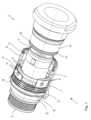
図1~図5に示されているコネクタ1は、コネクタ1の近位端3から遠位端4へ伸びている内部ハウジング2を備えている。典型的には、ケーブル(図示せず)は近位端3で内部ハウジング2に導入され、また、相手方コネクタ5の対応するコネクタ面と結合するコネクタ面(図示せず)は遠位端4に提供されている。つめリング6は、内部ハウジング2の上に取り付けられて、固定されている。図4および図5から最も良好に分かるように、つめリング6は、コネクタ1の遠位端4に向かって伸びている3個のつめ7を備えており、これらは互いに120°の角度で等しく間隔を隔てており、また、その全長はそれぞれ約60°の角度に亘っている。個々のつめ7の遠位端では、その内側は、コネクタ1の長手方向の軸に向かってテーパが施されており、それにより2個の係合ボール9のための支持部8を形成している。個々のつめ7には2個の開口10が提供されており、コネクタ1を組み立てる際には、この開口を通して、つめ7の外側から内側へ係合ボール9を導入することができる。 The
係合ボール9は、リング形ボール・ケージの形態の係合ボール駆動部11の中に保持されている。ボール・ケージは、6個のボール9を保持するための6個の開口を備えている。ボール9は、これらの開口を通って、ボール・ケージと内部ハウジング2の間の空間へ、所定の距離まで突出することができる。これらの開口には、ボール・ケージと内部ハウジングの間の空間に係合ボール9が落下するのを防止するために、ボール・ケージの内側に向かって内向きにテーパが施されている。係合ボール駆動部11は、図4に示されているように、つめリングのつめ7とつめ7の間をコネクタ1の近位端3に向かって伸びているつめ12をさらに備えている。個々のつめ12の近位端には、予め張力が掛けられた波ばね14によって遠位方向とは逆方向に示されているストップ13が備えられている。波ばね14は、コネクタ1の内部ハウジング2のリング形突起15の上に位置している。 The engaging
係合ボール駆動部11は、波ばね14の力に逆らって、コネクタ1の長手方向の軸に沿って、係合ボール駆動部11の静止位置であり、ロック位置とも呼ばれる遠位位置から、アンロック位置とも呼ばれる近位位置に向かって摺動可能となっている。遠位位置では、つめリング6のつめ7の支持部8のテーパ表面は、係合ボール9を係合ボール駆動部11の開口の内側に押し込み、したがってそれらは、ボール・ケージと内部ハウジング2の間の空間へ最大限に突出する。この状態は、係合ボールの係合位置とも呼ばれる。係合ボール駆動部11がその近位位置に向かって摺動すると、波ばね14が後退し、係合ボール駆動部11のつめ12がつめリング6のリング部分の上を通過する。それと同時に、係合ボール9がつめリング6のつめ7に対して近位方向に移動して、係合ボール9は、自由になり、開口から遠ざかって半径方向に、外側へ向かって移動するようになる。 The engagement ball drive 11 is unlocked along the longitudinal axis of the
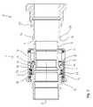
コネクタ1の外部ハウジング16は、外部ハウジング16のプレス・リング17を介して、コネクタ1の内部ハウジング2の上に摺動可能に取り付けられている。第1のシール・リング18は、内部ハウジング2に対して外部ハウジング16を封止している。外部ハウジング16の内側には、係合ボール駆動部11のカウンターキャッチと係合できるキャッチ19が提供されている。したがって外部ハウジング16がその遠位位置からその近位位置へ摺動すると、係合ボール駆動部11も同様にその遠位位置からその近位位置へ摺動する。一方、係合ボール駆動部11が波ばねの力によってその近位位置からその遠位位置へ摺動すると、外部ハウジング16も同様にその近位位置からその遠位位置へ摺動する。 The
図1および図2は、相手方コネクタ5から取り外された、その静止状態(resting configuration)にあるコネクタ1を示したものである。コネクタ1を相手方コネクタ5に取り付け、かつ、ロックするために、コネクタ1の内部ハウジング2は、第2のゴム・シール・リング21を通り越して相手方コネクタ5のハウジング20の中へ摺動する。そのために、オペレータは、コネクタ1の外部ハウジング16の部分でコネクタ1をグリップでき、あるいは好ましい場合、内部ハウジング2またはケーブルの露出部分などの任意の他の部分でコネクタ1をグリップできる。コネクタ1の内部ハウジング2が相手方コネクタ5のハウジング20の中へ摺動すると、相手方コネクタ5は、ボール・ケージと内部ハウジング2の間の空間の中に入る。相手方コネクタ5のハウジング20の前縁22は、ボール・ケージと内部ハウジング2の間の空間へ突出している係合ボール9の部分を押し退け、係合ボール9は、支持部8のテーパ表面に沿って外向きに摺動し、あるいは転がることによって後退し、それと同時に、波ばね14の力に逆らって係合ボール駆動部11を近位方向に移動させる。図3は、この位置における係合ボール(9)および係合ボール駆動部(11)を示したものである。このとき、コネクタ1の外部ハウジング16に影響を及ぼさず、コネクタ1の外部ハウジング16は、その遠位位置に留まることができる。引き続いて、相手方コネクタ5のハウジング20の前縁22が係合ボール9を通過し、また、相手方コネクタ5のハウジング20の外側の環状溝23が係合ボール9に到達すると、それらは、係合ボール駆動部11を介して、波ばね14の力によって環状溝23の中へ移動強制される。 1 and 2 show the
環状溝23の近位側との係合ボール9の係合は、コネクタ1を相手方コネクタ5にロックする。詳細には、コネクタ1および相手方コネクタ5に対して互いに引き離される方向に力が加えられる(例えば外力によって、あるいはコネクタ1および/または相手方コネクタ5の内側のプリストレス要素によって力が加えられる)と、係合ボール9は、相手方コネクタ5の係合部分24として作用する環状溝23の近位側と、コネクタ1の支持部8の表面の間にクランプされる。相手方コネクタ5の係合部分24およびコネクタの支持部8の表面は、相手方コネクタの係合部分24によって係合ボール9に加えられる力が、支持部8の表面によって係合ボール9に加えられる力とは逆にように形成され、かつ、そのように配置されている。これにより係合ボール9に作用する、係合ボール9をそれらの係合位置から動かし得る合力は存在しないこととなる。このことは、係合ボール駆動部11によって達成され得る。したがってこのコネクタは、対振動性および対衝撃性に優れており、また、プリストレスが加えられるコネクタのために適している。 Engagement of
コネクタ1を相手方コネクタ5からアンロックし、かつ、取り外すためには、オペレータは、コネクタ1の外部ハウジング16を近位方向に引っ張る。すると、外部ハウジング16は、その遠位位置からその近位位置へ摺動する。キャッチ19および係合ボール駆動部11のカウンターキャッチにより、外部ハウジング16は、外部ハウジング16と共に係合ボール駆動部11を移動させる。係合ボール駆動部11がその遠位位置からその近位位置に向かって移動すると、係合ボール9は、半径方向に、開口から遠ざかる外側に向かう方向に徐々に自由に移動するようになる。最終的には、それらは相手方コネクタ5の係合部分24から係合解除し、それによりコネクタ1を相手方コネクタ5からアンロックする。コネクタ1が相手方コネクタ5から外れると、波ばね14の力によって係合ボール動作手段11がその遠位位置へ戻り、また、係合ボール動作手段11と共にコネクタ1全体がその静止状態になる。 To unlock and remove
上記の説明、特許請求の範囲および図の中で説明されている特徴は、個別に、あるいは任意の組合せで関連して、本発明の様々な実施形態を実現し得る。
The features described in the above description, claims and figures, taken individually or in conjunction in any combination, enable various embodiments of the invention.
Claims (11)
Translated fromJapanese前記少なくとも1つの係合ボール(9)が、前記係合ボール駆動部(11)を介して、弾性要素(14)によって前記係合位置へバイアスされ、
キャッチを備えた外部ハウジングを有し、当該外部ハウジングが操作されると、係合ボール駆動部(11)が前記少なくとも1つの係合ボール(9)を前記係合位置から前記係合解除位置へ移動強制するよう、前記キャッチが前記係合ボール駆動部(11)のカウンターキャッチと係合して前記係合ボール駆動部(11)を移動させることを特徴とするコネクタ(1)。A connector (1) comprising at least one engagement ball (9) movable between an engaged position and a disengaged position, said connector (1) to an inner housing (2) of said connector (1). 1) movement of the engaging ball driving portion (11) forces the at least one engaging ball (9) to move from the engaging position to the disengaging position;
said at least one engaging ball (9) is biased to said engaged position by a resilient element (14) via said engaging ball drive (11);
an outer housing with a catch, the engagement ball drive (11) moving the at least one engagement ball (9) from the engagement position to the disengagement position when the outer housing is operated; A connector (1) characterized in that said catch engages a counter catch of said engaging ball drive (11) to move said engaging ball drive (11) so as to force it to move.
内部ハウジング(2)および外部ハウジング(16)を備え、前記外部ハウジング(16)が、前記内部ハウジング(2)に対して、前記コネクタ(1)の長手方向に移動可能に配され、前記外部ハウジング(16)が前記内部ハウジング(2)に対して相対移動すると、前記係合ボール駆動部(11)が移動して前記少なくとも1つの係合ボール(9)を前記係合位置から前記係合解除位置へ移動させるように、前記外部ハウジング(16)が前記係合ボール駆動部(11)と動作可能に接続されることを特徴とするコネクタ(1)。A connector (1) according to claim 1, characterized in that
an inner housing (2) and an outer housing (16), wherein the outer housing (16) is movably arranged relative to the inner housing (2) in the longitudinal direction of the connector (1); When (16) moves relative to said inner housing (2), said engaging ball drive (11) moves to move said at least one engaging ball (9) from said engaged position to said disengaged position. A connector (1) characterized in that said outer housing (16) is operatively connected with said engagement ball drive (11) so as to move it into position.
前記係合ボール駆動部(11)の前記移動が前記コネクタ(1)の長手方向であることを特徴とするコネクタ(1)。A connector (1) according to claim 1 or 2,
A connector (1), characterized in that said movement of said engagement ball drive (11) is in the longitudinal direction of said connector (1).
前記係合ボール(9)が前記係合位置にあるとき、前記係合ボール(9)が、前記コネクタ(1)を相手方コネクタ(5)に確実に取り付けるために、前記係合ボール(9)との係合のために前記相手方コネクタ(5)の係合部分(24)を配置するのに適した空間へ突出することを特徴とするコネクタ(1)。A connector (1) according to any one of claims 1 to 3,
In order for the engagement ball (9) to securely attach the connector (1) to the mating connector (5) when the engagement ball (9) is in the engagement position, the engagement ball (9) A connector (1), characterized in that it projects into a space suitable for locating the engaging portion (24) of said mating connector (5) for engagement with.
前記係合位置と前記係合解除位置の間の前記少なくとも1つの係合ボール(9)の前記移動が、前記コネクタ(1)の半径方向の成分を有することを特徴とするコネクタ(1)。A connector (1) according to any one of claims 1 to 4,
A connector (1), characterized in that said movement of said at least one engaging ball (9) between said engaged position and said disengaged position has a component in the radial direction of said connector (1).
少なくとも前記係合位置では、前記少なくとも1つの係合ボール(9)が少なくとも1つの支持部(8)の表面で静止し、前記表面に、前記コネクタ(1)の長手方向のその延長部分に沿ってテーパが施されることを特徴とするコネクタ(1)。A connector (1) according to any one of claims 1 to 5,
At least in said engaged position, said at least one engaging ball (9) rests on the surface of at least one support (8) and extends on said surface along its longitudinal extension of said connector (1). A connector (1) characterized in that it is tapered at the bottom.
前記外部ハウジングの前記キャッチおよび前記係合ボール駆動部(11)の前記カウンターキャッチが、前記少なくとも1つの係合ボール(9)がその係合位置にある位置から、前記少なくとも1つの係合ボール(9)がその係合解除位置にある位置へ前記係合ボール駆動部(11)が移動する際に、当該係合ボール駆動部(11)のこの移動が前記外部ハウジングの移動に変換されないよう形成され、かつ、配置されることを特徴とするコネクタ(1)。A connector (1) according to claim 1, characterized in that
The catch of the outer housing and the counter-catch of the engaging ball drive (11) move from the position where the at least one engaging ball (9) is in its engaged position to the at least one engaging ball ( 9) is in its disengaged position, this movement of said engaging ball drive (11) is not translated into movement of said outer housing. A connector (1), characterized in that:
少なくとも2個の係合ボール(9)を備えることを特徴とするコネクタ(1)。A connector (1) according to any one of claims 1 to 7,
A connector (1) characterized in that it comprises at least two engaging balls (9).
前記コネクタ(1)が前記相手方コネクタ(5)にロックされると、前記コネクタ(1)の少なくとも1つの支持部(8)が、前記相手方コネクタ(5)によって前記係合ボール(9)に加えられる力に逆らって前記少なくとも1つの係合ボール(9)をロック位置で保持し、前記コネクタ(1)の前記少なくとも1つの支持部(8)と前記相手方コネクタ(5)の前記係合部分(24)の間に通路が形成され、また、係合ボール駆動部(11)が、前記少なくとも1つの係合ボール(9)を前記通路に沿って前記係合位置から係合解除位置へ移動強制可能となっていることを特徴とするシステム。10. The system of claim 9, wherein
When said connector (1) is locked to said mating connector (5), at least one support (8) of said connector (1) is applied to said mating ball (9) by said mating connector (5). holding said at least one engaging ball (9) in a locked position against a force exerted against said at least one supporting portion (8) of said connector (1) and said engaging portion of said mating connector (5). 24), and an engagement ball drive (11) forcing said at least one engagement ball (9) to move along said passage from said engagement position to a disengagement position. A system characterized in that it enables
前記係合ボール(9)が、前記係合ボール駆動部(11)を介して、弾性要素(14)によって前記ロック位置へバイアスされており、
前記コネクタ(1)の外部ハウジングが内部ハウジングに対して移動し、外部ハウジング(16)のキャッチが係合ボール駆動部(11)のカウンターキャッチに係合し、前記外部ハウジング(16)が係合ボール駆動部(11)を移動させ、当該係合ボール駆動部(11)が前記係合ボール(9)を前記ロック位置から前記アンロック位置へ移動強制する方法。
A method for unlocking a connector (1) from a mating connector (5),wherein the engagement ball (9) of the connector (1) is moved to the engagement ball ( 9) engages the mating portion (24) of said mating connector (5) to lock said connector (1) to said mating connector (5), said mating ball (9) is no longer said A method of unlocking by moving the mating connector (5) to an unlocking position where it does not engage with the engaging portion (24), comprising:
said engaging ball (9) is biased to saidlocking position by a resilient element (14) via said engaging ball drive (11);
The outer housing of said connector (1) moves relative to the inner housing, the catch of outer housing (16) engages the counter catch of engaging ball drive (11) and said outer housing (16) engages. A method of moving a ball driving part (11) and forcing said engaging ball driving part (11) to move said engaging ball (9) from said locking position to said unlocking position.
Applications Claiming Priority (2)
| Application Number | Priority Date | Filing Date | Title |
|---|---|---|---|
| EP19196036.8 | 2019-09-06 | ||
| EP19196036.8AEP3789648B1 (en) | 2019-09-06 | 2019-09-06 | Ball-lock connector |
Publications (2)
| Publication Number | Publication Date |
|---|---|
| JP2021044232A JP2021044232A (en) | 2021-03-18 |
| JP7228546B2true JP7228546B2 (en) | 2023-02-24 |
Family
ID=67875410
Family Applications (1)
| Application Number | Title | Priority Date | Filing Date |
|---|---|---|---|
| JP2020127748AActiveJP7228546B2 (en) | 2019-09-06 | 2020-07-28 | ball-lock connector |
Country Status (6)
| Country | Link |
|---|---|
| US (1) | US11668334B2 (en) |
| EP (1) | EP3789648B1 (en) |
| JP (1) | JP7228546B2 (en) |
| KR (1) | KR102536620B1 (en) |
| CN (1) | CN112467473B (en) |
| RU (1) | RU2748941C1 (en) |
Families Citing this family (6)
| Publication number | Priority date | Publication date | Assignee | Title |
|---|---|---|---|---|
| CN115117669B (en)* | 2021-03-19 | 2025-07-04 | 泰科电子(上海)有限公司 | Connectors and Connector Assemblies |
| CN113062454B (en)* | 2021-03-30 | 2022-12-06 | 山西宏厚装配式建筑科技发展有限公司 | Steel structure beam column frame assembling type process |
| TWI820765B (en)* | 2021-08-16 | 2023-11-01 | 顏玉惠 | Connector shroud |
| USD1006595S1 (en)* | 2021-10-26 | 2023-12-05 | Gem Products, Llc | Latch backing plate |
| CN115978375A (en)* | 2022-10-21 | 2023-04-18 | 广东安达智能装备股份有限公司 | A quick connection structure and intelligent platform system |
| FR3157241A1 (en)* | 2023-12-20 | 2025-06-27 | Smw Autoblok | Mandrel assembly system |
Citations (2)
| Publication number | Priority date | Publication date | Assignee | Title |
|---|---|---|---|---|
| US20030129873A1 (en) | 2002-01-09 | 2003-07-10 | Clark Heebe | Coaxial cable quick connect/disconnect connector |
| CN101656381B (en) | 2008-08-22 | 2011-12-21 | 贵州航天电器股份有限公司 | High power radio frequency connector capable of quickly locking and separating |
Family Cites Families (47)
| Publication number | Priority date | Publication date | Assignee | Title |
|---|---|---|---|---|
| US2665928A (en)* | 1948-10-27 | 1954-01-12 | Case Co J I | Coupling |
| FR1384065A (en) | 1963-11-12 | 1965-01-04 | Staubli Freres & Cie | Quick coupling device for pipes and the like |
| US3567175A (en)* | 1968-10-08 | 1971-03-02 | Stile Craft Mfg Inc | Quick release coupling |
| US3715099A (en)* | 1971-06-02 | 1973-02-06 | Crawford Fitting Co | Valved quick-disconnect coupling |
| US4014467A (en)* | 1975-11-03 | 1977-03-29 | Duff-Norton Company, Inc. | Dishwasher and coupling |
| FR2366475A1 (en)* | 1976-10-04 | 1978-04-28 | Salanon Sa | AUTOMATIC SWITCHING QUICK CONNECTOR |
| US4198080A (en)* | 1978-05-19 | 1980-04-15 | Baxter Travenol Laboratories, Inc. | Telescoping-type connector |
| US4213482A (en)* | 1978-10-25 | 1980-07-22 | Gondek John T | Hydraulic coupler |
| WO1980001311A1 (en)* | 1978-12-20 | 1980-06-26 | Abnox Ag | Pipe coupling |
| FR2484053A2 (en) | 1980-06-06 | 1981-12-11 | Fremy Raoul | Quick disconnect pipe coupling - can be separated by axial movement of spring loaded sliding locking sleeve which has locking rollers seated in groove |
| FR2527741B1 (en) | 1982-06-01 | 1986-02-21 | Staubli Sa Ets | IMPROVEMENTS ON QUICK CONNECTIONS FOR REMOVABLE JOINING OF PIPES |
| US4645372A (en)* | 1984-10-01 | 1987-02-24 | Matsui-Walterschield Ltd. | Power transmitting coupling |
| DE3445129C2 (en) | 1984-12-11 | 1986-11-20 | Rectus-Apparatebau Walter Klein Gmbh, 7147 Eberdingen | Vent coupling |
| JPH0755855Y2 (en)* | 1988-02-04 | 1995-12-25 | ケーエス・サノヤス株式会社 | Rotating joint connection structure |
| US4859110A (en)* | 1988-09-21 | 1989-08-22 | Neapco, Inc. | Automatic coupling device |
| US4932431A (en)* | 1989-08-07 | 1990-06-12 | Tuthill Corporation | Coupling with heat fusible actuator member |
| JPH0753032Y2 (en)* | 1991-06-11 | 1995-12-06 | 日東工器株式会社 | Pipe fitting |
| EP0536434B1 (en)* | 1991-10-08 | 1994-09-28 | RECTUS-APPARATEBAU Walter Klein GmbH | Self-vented quick coupling for pressurized gas pipes, especially for compressed air pipes |
| US5366313A (en)* | 1992-11-02 | 1994-11-22 | Norco, Inc. | Strut construction |
| US5540250A (en)* | 1994-03-22 | 1996-07-30 | Perfecting Coupling Company | Quick-disconnect fluid coupling |
| US5445358A (en)* | 1994-12-16 | 1995-08-29 | Parker-Hannifin Corporation | Exhaust type quick action coupler |
| JPH0992395A (en)* | 1995-09-20 | 1997-04-04 | Sumitomo Wiring Syst Ltd | Locking mechanism for connector |
| JPH0992295A (en) | 1995-09-21 | 1997-04-04 | Matsushita Electric Ind Co Ltd | Manufacturing method of air electrode for button type zinc-air battery |
| SE506405C2 (en)* | 1996-03-22 | 1997-12-15 | Nyberg Bo Erik | Quick release with pressure relief for safe release |
| JP2909020B2 (en)* | 1996-06-11 | 1999-06-23 | ナスコフィッティング株式会社 | Pipe fittings |
| FR2786848B1 (en)* | 1998-12-02 | 2001-02-09 | Legris Sa | BALL COUPLER |
| JP3983728B2 (en)* | 2003-09-18 | 2007-09-26 | 日東工器株式会社 | Pipe fittings and sockets for pipe fittings |
| JP4484143B2 (en)* | 2004-06-09 | 2010-06-16 | 日東工器株式会社 | Plug / socket assembly |
| CN2729951Y (en) | 2004-09-08 | 2005-09-28 | 贵州航天电器股份有限公司 | Ball type quick push-pull locking and unlocking electric connector |
| US7841580B2 (en)* | 2005-04-18 | 2010-11-30 | Macro Technologies, Inc. | Pressurized fluid coupler with anti-recoil feature and methods |
| FR2890719B1 (en)* | 2005-09-14 | 2007-10-12 | Staubli Faverges Sca | QUICK CONNECTION OF SECURITY FOR THE JOINING OF TWO PIPES |
| US8056581B2 (en)* | 2006-04-06 | 2011-11-15 | Fastest, Inc. | Latching connectors |
| JP4831619B2 (en)* | 2006-11-24 | 2011-12-07 | 日東工器株式会社 | Joint, socket and plug used for this joint |
| US20080315581A1 (en)* | 2007-01-29 | 2008-12-25 | White Davis A | Non-Rotating Coupling Device |
| KR101260115B1 (en)* | 2008-02-28 | 2013-05-02 | 니토 코키 가부시키가이샤 | Socket for pipe coupling and pipe coupling |
| JP5391137B2 (en) | 2010-04-22 | 2014-01-15 | カナレ電気株式会社 | Ball lock connector |
| US8844942B1 (en)* | 2010-06-25 | 2014-09-30 | Greatbatch Ltd. | Quick-load connector for a surgical tool |
| RU2487782C2 (en)* | 2011-02-10 | 2013-07-20 | Геннадий Михайлович Целковнев | Connector of modules |
| US20120243932A1 (en) | 2011-03-23 | 2012-09-27 | GM Global Technology Operations LLC | Quick release vehicle accessory connection system |
| CH705122A1 (en) | 2011-06-16 | 2012-12-31 | Arx Ag | Quick coupling for connecting a replaceable head. |
| CN102856723A (en) | 2012-03-29 | 2013-01-02 | 中航光电科技股份有限公司 | Plug with looseness-prevention connecting nut and connector assembly |
| FR2998637B1 (en)* | 2012-11-23 | 2015-06-26 | Staubli Sa Ets | RAPID COUPLING FEMALE ELEMENT AND RAPID CONNECTION INCORPORATING SUCH A MEMBER |
| JP2018515731A (en)* | 2015-04-24 | 2018-06-14 | ジェネラル・プラズマ・インコーポレーテッド | Push-type connection and pull-type separated quick fitting |
| US9502822B1 (en)* | 2015-12-01 | 2016-11-22 | Chung-Chuan Huang | Ball-lock axial connector assembly |
| DE102016105975A1 (en) | 2016-04-01 | 2017-10-05 | Harting Ag & Co. Kg | Locking device for connectors |
| CN106848740A (en)* | 2017-01-23 | 2017-06-13 | 中航光电科技股份有限公司 | A kind of connector and its lock sleeve |
| CN207965228U (en) | 2017-11-14 | 2018-10-12 | 烽火通信科技股份有限公司 | A kind of joint of connector, adapter and fast insert-pull |
- 2019
- 2019-09-06EPEP19196036.8Apatent/EP3789648B1/enactiveActive
- 2020
- 2020-07-21RURU2020124225Apatent/RU2748941C1/enactive
- 2020-07-28JPJP2020127748Apatent/JP7228546B2/enactiveActive
- 2020-09-02CNCN202010909479.6Apatent/CN112467473B/enactiveActive
- 2020-09-03KRKR1020200112220Apatent/KR102536620B1/enactiveActive
- 2020-09-04USUS17/012,249patent/US11668334B2/enactiveActive
Patent Citations (2)
| Publication number | Priority date | Publication date | Assignee | Title |
|---|---|---|---|---|
| US20030129873A1 (en) | 2002-01-09 | 2003-07-10 | Clark Heebe | Coaxial cable quick connect/disconnect connector |
| CN101656381B (en) | 2008-08-22 | 2011-12-21 | 贵州航天电器股份有限公司 | High power radio frequency connector capable of quickly locking and separating |
Also Published As
| Publication number | Publication date |
|---|---|
| EP3789648C0 (en) | 2024-01-03 |
| US11668334B2 (en) | 2023-06-06 |
| KR102536620B1 (en) | 2023-05-25 |
| JP2021044232A (en) | 2021-03-18 |
| CN112467473A (en) | 2021-03-09 |
| US20210071698A1 (en) | 2021-03-11 |
| KR20210030208A (en) | 2021-03-17 |
| RU2748941C1 (en) | 2021-06-02 |
| EP3789648A1 (en) | 2021-03-10 |
| EP3789648B1 (en) | 2024-01-03 |
| CN112467473B (en) | 2023-03-24 |
Similar Documents
| Publication | Publication Date | Title |
|---|---|---|
| JP7228546B2 (en) | ball-lock connector | |
| US6039303A (en) | High pressure fluidline connector | |
| EP3656510B1 (en) | Connection structure of operation rod | |
| JP5491526B2 (en) | Self-injector | |
| US10156252B2 (en) | Cable couplings for drain cleaning tools | |
| TWI427231B (en) | Female element for a connector and connector comprising such a female element | |
| US6581907B1 (en) | Pipe coupling | |
| KR101497712B1 (en) | Tools for detachably connecting tool accessories | |
| CN112368448A (en) | Coupling device | |
| US20200224698A1 (en) | Anti-vibration locking connector | |
| US20090049958A1 (en) | Tools for detachably engaging tool attachments | |
| US4907981A (en) | Quick-release electrical connector coupling device | |
| CN218383386U (en) | Optical fiber coupling structure, optical fiber coupling seat, optical fiber plug and photoacoustic imaging system | |
| US20020052134A1 (en) | Releasable fastening device, such as for an electrical computer connector, and methods for releasable fastening an electrical computer connector to a computer component | |
| KR102250122B1 (en) | One touch high pressure connect | |
| JP2009287612A (en) | Pipe joint | |
| US5825837A (en) | Extraction tool for partial length fuel rods in nuclear fuel assemblies | |
| JP5245527B2 (en) | Piping plug attachment / detachment tool | |
| JPH05266947A (en) | Connecting and disconnecting device for connector | |
| US5445419A (en) | Split-ring breakaway connector | |
| JP3253064U (en) | Coupler fittings | |
| CN223413527U (en) | Switching structure | |
| US20070237603A1 (en) | Quick acting coupling device | |
| CN116407287A (en) | Surgical instrument fixing mechanism, surgical tool and surgical robot | |
| WO1994027080A2 (en) | Split-ring breakaway connector |
Legal Events
| Date | Code | Title | Description |
|---|---|---|---|
| A621 | Written request for application examination | Free format text:JAPANESE INTERMEDIATE CODE: A621 Effective date:20201221 | |
| A977 | Report on retrieval | Free format text:JAPANESE INTERMEDIATE CODE: A971007 Effective date:20211011 | |
| A131 | Notification of reasons for refusal | Free format text:JAPANESE INTERMEDIATE CODE: A131 Effective date:20211019 | |
| A601 | Written request for extension of time | Free format text:JAPANESE INTERMEDIATE CODE: A601 Effective date:20220118 | |
| A521 | Request for written amendment filed | Free format text:JAPANESE INTERMEDIATE CODE: A523 Effective date:20220318 | |
| A131 | Notification of reasons for refusal | Free format text:JAPANESE INTERMEDIATE CODE: A131 Effective date:20220712 | |
| A521 | Request for written amendment filed | Free format text:JAPANESE INTERMEDIATE CODE: A523 Effective date:20221005 | |
| TRDD | Decision of grant or rejection written | ||
| A01 | Written decision to grant a patent or to grant a registration (utility model) | Free format text:JAPANESE INTERMEDIATE CODE: A01 Effective date:20230124 | |
| A61 | First payment of annual fees (during grant procedure) | Free format text:JAPANESE INTERMEDIATE CODE: A61 Effective date:20230213 | |
| R150 | Certificate of patent or registration of utility model | Ref document number:7228546 Country of ref document:JP Free format text:JAPANESE INTERMEDIATE CODE: R150 |