JP7226437B2 - Video display device - Google Patents
Video display deviceDownload PDFInfo
- Publication number
- JP7226437B2 JP7226437B2JP2020516105AJP2020516105AJP7226437B2JP 7226437 B2JP7226437 B2JP 7226437B2JP 2020516105 AJP2020516105 AJP 2020516105AJP 2020516105 AJP2020516105 AJP 2020516105AJP 7226437 B2JP7226437 B2JP 7226437B2
- Authority
- JP
- Japan
- Prior art keywords
- image
- display device
- image display
- screen
- horizontal direction
- Prior art date
- Legal status (The legal status is an assumption and is not a legal conclusion. Google has not performed a legal analysis and makes no representation as to the accuracy of the status listed.)
- Active
Links
Images


Classifications
- H—ELECTRICITY
- H04—ELECTRIC COMMUNICATION TECHNIQUE
- H04N—PICTORIAL COMMUNICATION, e.g. TELEVISION
- H04N13/00—Stereoscopic video systems; Multi-view video systems; Details thereof
- H04N13/30—Image reproducers
- H04N13/349—Multi-view displays for displaying three or more geometrical viewpoints without viewer tracking
- H04N13/351—Multi-view displays for displaying three or more geometrical viewpoints without viewer tracking for displaying simultaneously
- G—PHYSICS
- G02—OPTICS
- G02B—OPTICAL ELEMENTS, SYSTEMS OR APPARATUS
- G02B26/00—Optical devices or arrangements for the control of light using movable or deformable optical elements
- G02B26/08—Optical devices or arrangements for the control of light using movable or deformable optical elements for controlling the direction of light
- G02B26/0808—Optical devices or arrangements for the control of light using movable or deformable optical elements for controlling the direction of light by means of one or more diffracting elements
- G—PHYSICS
- G02—OPTICS
- G02B—OPTICAL ELEMENTS, SYSTEMS OR APPARATUS
- G02B26/00—Optical devices or arrangements for the control of light using movable or deformable optical elements
- G02B26/08—Optical devices or arrangements for the control of light using movable or deformable optical elements for controlling the direction of light
- G02B26/0816—Optical devices or arrangements for the control of light using movable or deformable optical elements for controlling the direction of light by means of one or more reflecting elements
- G02B26/0833—Optical devices or arrangements for the control of light using movable or deformable optical elements for controlling the direction of light by means of one or more reflecting elements the reflecting element being a micromechanical device, e.g. a MEMS mirror, DMD
- G—PHYSICS
- G02—OPTICS
- G02B—OPTICAL ELEMENTS, SYSTEMS OR APPARATUS
- G02B30/00—Optical systems or apparatus for producing three-dimensional [3D] effects, e.g. stereoscopic images
- G02B30/50—Optical systems or apparatus for producing three-dimensional [3D] effects, e.g. stereoscopic images the image being built up from image elements distributed over a 3D volume, e.g. voxels
- G02B30/56—Optical systems or apparatus for producing three-dimensional [3D] effects, e.g. stereoscopic images the image being built up from image elements distributed over a 3D volume, e.g. voxels by projecting aerial or floating images
- G—PHYSICS
- G03—PHOTOGRAPHY; CINEMATOGRAPHY; ANALOGOUS TECHNIQUES USING WAVES OTHER THAN OPTICAL WAVES; ELECTROGRAPHY; HOLOGRAPHY
- G03B—APPARATUS OR ARRANGEMENTS FOR TAKING PHOTOGRAPHS OR FOR PROJECTING OR VIEWING THEM; APPARATUS OR ARRANGEMENTS EMPLOYING ANALOGOUS TECHNIQUES USING WAVES OTHER THAN OPTICAL WAVES; ACCESSORIES THEREFOR
- G03B35/00—Stereoscopic photography
- G03B35/18—Stereoscopic photography by simultaneous viewing
- G03B35/22—Stereoscopic photography by simultaneous viewing using single projector with stereoscopic-base-defining system
- H—ELECTRICITY
- H04—ELECTRIC COMMUNICATION TECHNIQUE
- H04N—PICTORIAL COMMUNICATION, e.g. TELEVISION
- H04N13/00—Stereoscopic video systems; Multi-view video systems; Details thereof
- H04N13/30—Image reproducers
- H04N13/363—Image reproducers using image projection screens
- H—ELECTRICITY
- H04—ELECTRIC COMMUNICATION TECHNIQUE
- H04N—PICTORIAL COMMUNICATION, e.g. TELEVISION
- H04N9/00—Details of colour television systems
- H04N9/12—Picture reproducers
- H04N9/31—Projection devices for colour picture display, e.g. using electronic spatial light modulators [ESLM]
- H04N9/3141—Constructional details thereof
- H04N9/315—Modulator illumination systems
- H04N9/3152—Modulator illumination systems for shaping the light beam
- H—ELECTRICITY
- H04—ELECTRIC COMMUNICATION TECHNIQUE
- H04N—PICTORIAL COMMUNICATION, e.g. TELEVISION
- H04N9/00—Details of colour television systems
- H04N9/12—Picture reproducers
- H04N9/31—Projection devices for colour picture display, e.g. using electronic spatial light modulators [ESLM]
- H04N9/3141—Constructional details thereof
- H04N9/315—Modulator illumination systems
- H04N9/3161—Modulator illumination systems using laser light sources
- H—ELECTRICITY
- H04—ELECTRIC COMMUNICATION TECHNIQUE
- H04N—PICTORIAL COMMUNICATION, e.g. TELEVISION
- H04N9/00—Details of colour television systems
- H04N9/12—Picture reproducers
- H04N9/31—Projection devices for colour picture display, e.g. using electronic spatial light modulators [ESLM]
- H04N9/3141—Constructional details thereof
- H04N9/315—Modulator illumination systems
- H04N9/3164—Modulator illumination systems using multiple light sources
- G—PHYSICS
- G03—PHOTOGRAPHY; CINEMATOGRAPHY; ANALOGOUS TECHNIQUES USING WAVES OTHER THAN OPTICAL WAVES; ELECTROGRAPHY; HOLOGRAPHY
- G03B—APPARATUS OR ARRANGEMENTS FOR TAKING PHOTOGRAPHS OR FOR PROJECTING OR VIEWING THEM; APPARATUS OR ARRANGEMENTS EMPLOYING ANALOGOUS TECHNIQUES USING WAVES OTHER THAN OPTICAL WAVES; ACCESSORIES THEREFOR
- G03B21/00—Projectors or projection-type viewers; Accessories therefor
- G03B21/54—Accessories
- G03B21/56—Projection screens
- G03B21/60—Projection screens characterised by the nature of the surface
- G03B21/606—Projection screens characterised by the nature of the surface for relief projection
Landscapes
- Physics & Mathematics (AREA)
- Optics & Photonics (AREA)
- Engineering & Computer Science (AREA)
- Multimedia (AREA)
- Signal Processing (AREA)
- General Physics & Mathematics (AREA)
- Testing, Inspecting, Measuring Of Stereoscopic Televisions And Televisions (AREA)
- Transforming Electric Information Into Light Information (AREA)
- Projection Apparatus (AREA)
Description
Translated fromJapanese本開示は、複数の視点映像を表示する映像表示装置に関する。 The present disclosure relates to a video display device that displays multiple viewpoint videos.
それぞれ異なる視点から見た複数の映像(視点映像)を表示する技術がある。例えば、複数の発光点から照射された複数のレーザ光を独立に走査、偏向して複数の視点映像を表示する技術がある(特許文献1参照)。これにより、例えば立体映像表示を行う技術がある。 There is a technology for displaying a plurality of images (viewpoint images) viewed from different viewpoints. For example, there is a technique of independently scanning and deflecting a plurality of laser beams emitted from a plurality of light emitting points to display a plurality of viewpoint images (see Patent Document 1). Accordingly, there is a technique for displaying a stereoscopic image, for example.
上記技術では、複数のレーザ光を発する複数の視点数分の光源や、複数のレーザ光の状態を制御するレンズ等の複数の光学素子が必要とされ得る。また、小さいレンズのアレイで偏向を行って視点映像を表示しているため、正しい方向に所望の映像を表示するためには広い範囲でレンズとレーザの高い位置精度が求められる。そのため、装置全体として大型化やコスト高を招く。 The above technology may require light sources for a plurality of viewpoints for emitting a plurality of laser beams, and a plurality of optical elements such as lenses for controlling the states of the plurality of laser beams. In addition, since the viewpoint image is displayed by deflection with an array of small lenses, high positional accuracy of the lens and laser is required over a wide range in order to display the desired image in the correct direction. Therefore, the size and cost of the apparatus as a whole are increased.
小型、低コストで多視点の映像表示を行うことが可能な映像表示装置を提供することが望ましい。 It is desirable to provide a video display device capable of displaying multi-viewpoint video in a small size and at low cost.
本開示の一実施の形態に係る映像表示装置は、投影映像を出射する少なくとも1つの映像源と、映像源からの投影映像を少なくとも水平方向の複数のエリアに分割して複数のエリア映像を生成し、複数のエリア映像が異方性拡散特性を持つスクリーン上で部分的に重ね合わさることで複数視点の映像表示が行われるように、複数のエリア映像をそれぞれスクリーンに向けて互いに異なる角度で偏向投影する、少なくとも1つの映像偏向部とを備えるものである。そして、スクリーンを円筒スクリーンとし、映像偏向部が、複数のエリア映像のそれぞれの映像中心光線が円筒スクリーンの円筒軸を通過するように、複数のエリア映像のそれぞれを円筒スクリーンに向けて偏向投影するようにしたものである。
An image display device according to an embodiment of the present disclosure includes at least one image source that emitsa projected image, and divides the projected image from the image source into at least a plurality of horizontal areas to display a plurality of area images. Multiple area images are directed toward the screen at different angles so that images from multiple viewpoints can be displayed by partially overlapping multiple area images on a screen with anisotropic diffusion characteristics. and at least one image deflection unit for deflection projection.Then, the screen is a cylindrical screen, and the image deflection unit deflects and projects each of the plurality of area images toward the cylindrical screen so that the image center ray of each of the plurality of area images passes through the cylindrical axis of the cylindrical screen. It is designed to
本開示の一実施の形態に係る映像表示装置では、映像偏向部によって、映像源からの投影映像が少なくとも水平方向の複数のエリアに分割され、複数のエリア映像が生成される。映像偏向部は、複数のエリア映像が異方性拡散特性を持つスクリーン上で部分的に重ね合わさることで複数視点の映像表示が行われるように、複数のエリア映像のそれぞれをスクリーンに向けて互いに異なる角度で偏向投影する。 In the image display device according to the embodiment of the present disclosure, the image deflecting unit divides the projection image from the image source into at least a plurality of horizontal areas to generate a plurality of area images. The image deflection unit directs each of the plurality of area images toward the screen so that image display from multiple viewpoints is performed by partially overlapping the plurality of area images on the screen having anisotropic diffusion characteristics. Deflection projection at different angles.
以下、本開示の実施の形態について図面を参照して詳細に説明する。なお、説明は以下の順序で行う。 Hereinafter, embodiments of the present disclosure will be described in detail with reference to the drawings. The description will be given in the following order.
1.第1の実施の形態(平面型のスクリーンを用いる映像表示装置)
1.0 比較例(図1)
1.1 第1の実施の形態に係る映像表示装置の構成および動作(図2~図6)
1.2 効果
2.第2の実施の形態(円筒型のスクリーンを用いる映像表示装置)(図7~図10)
3.第3の実施の形態(映像偏向部のバリエーション)(図11~図14)
4.第4の実施の形態(映像偏向部を複数段のアレイで構成した例)(図15~図17)
5.第5の実施の形態(映像源のバリエーション)(図18)
6.その他の実施の形態
1. First embodiment (video display device using a flat screen)
1.0 Comparative example (Fig. 1)
1.1 Configuration and Operation of Image Display Device According to First Embodiment (FIGS. 2 to 6)
1.2
3. Third Embodiment (Variation of Image Deflection Unit) (FIGS. 11 to 14)
4. Fourth embodiment (an example in which the image deflection unit is configured with a plurality of stages of arrays) (Figs. 15 to 17)
5. Fifth Embodiment (Variation of Image Source) (Fig. 18)
6. Other embodiments
<1.第1の実施の形態>
[1.0 比較例]
(比較例に係る映像表示装置の概要と課題)
図1は、比較例に係る映像表示装置の概要を示している。<1. First Embodiment>
[1.0 Comparative Example]
(Overview and Problems of Video Display Apparatus According to Comparative Example)
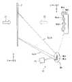
FIG. 1 shows an overview of a video display device according to a comparative example.
比較例に係る映像表示装置は、映像源としてのプロジェクタ100を複数、アレイ状に配置し、異方性拡散特性を持つスクリーン200に向けて、各々のプロジェクタ100から映像を投射して立体映像を表示する。 The image display apparatus according to the comparative example has a plurality of
比較例に係る映像表示装置では、1つのプロジェクタ100から1つの視点分の映像を出射する。このため、複数の視点映像を表示するためには、視点数分の映像源(プロジェクタ100)が必要であり、全体として、大規模な装置となってしまう。比較例に係る映像表示装置では、各映像源の基点は円周上にあり、個々のプロジェクタ100を小さくしても、装置全体としてのサイズを小さくすることは困難である。 In the video display device according to the comparative example, one
[1.1 第1の実施の形態に係る映像表示装置の構成および動作]
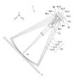
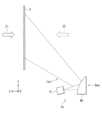
図2~図4は、本開示の第1の実施の形態に係る映像表示装置1の一構成例を概略的に示している。図2は、上面方向から見た映像表示装置1の全体構成の一例を示している。図3は、上面方向から見た映像表示装置1における映像源Pjからの投影映像(投影光)Lpjの一例を示している。図4は、側面方向から見た映像表示装置1の一構成例を概略的に示している。なお、図2等において、Xは水平方向、Yは垂直方向、Zは投影方向を示す。後述する他の実施の形態において示す図においても同様である。[1.1 Configuration and Operation of Video Display Device According to First Embodiment]
2 to 4 schematically show one configuration example of the
第1の実施の形態に係る映像表示装置1は、2次元的な投影映像Lpjを出射する映像源Pjと、投影映像Lpjから分割された複数のエリア映像Lpjnのそれぞれをスクリーン2に向けて互いに異なる角度で偏向投影する映像偏向部Deとを備えている。複数のエリア映像Lpjnはそれぞれ、互いに視点の異なる視点映像に相当する。 The
スクリーン2は、例えば、水平方向と垂直方向とで光拡散特性が異なる透過型または反射型の異方性拡散特性を持つ平面スクリーンである。スクリーン2は、例えば、異方性拡散板である。スクリーン2は、水平方向と垂直方向とで光拡散特性が異なる異方性拡散特性を持つ回折素子であってもよい。回折素子は、ホログラフィック光学素子(HOE:Holographic Optical Element)であってもよい。スクリーン2の異方性拡散特性は、例えば水平方向は相対的に狭拡散、垂直方向は相対的に広拡散であることが望ましい。水平方向は狭拡散とすることで、異なる角度から投影される複数の視点映像が不必要に混じり合うことを抑制することができる。 The
なお、図4において、Z1は、スクリーン2が透過型の場合の観察方向を示す。Z2は、スクリーン2が反射型の場合の観察方向を示す。後述する他の実施の形態において示す図においても同様である。 In FIG. 4, Z1 indicates the observation direction when the
映像源Pjは、時間的または空間的に2次元に光線を出射することで、2次元的な投影映像Lpjを生成する。映像源Pjは、スクリーン2と映像偏向部Deとの間に配置されている The image source Pj generates a two-dimensional projected image Lpj by emitting light rays two-dimensionally temporally or spatially. The image source Pj is arranged between the
映像源Pjは、例えば、反射型液晶素子を用いて投影映像Lpjを生成するLCOS(Liquid Crystal On Silicon)型のプロジェクタ(反射型液晶プロジェクタ)であってもよい。この場合、映像源Pjは、空間的に2次元に光線を出射することで、2次元的な投影映像Lpjを生成する。 The image source Pj may be, for example, an LCOS (Liquid Crystal On Silicon) type projector (reflective liquid crystal projector) that generates a projected image Lpj using a reflective liquid crystal element. In this case, the image source Pj generates a two-dimensional projected image Lpj by spatially emitting light rays two-dimensionally.
また、映像源Pjは、例えば、投影映像Lpjを2次元配列された複数の可動ミラーによって生成するプロジェクタであってもよい。例えば、映像源Pjは、DMD(Digital Micromirror Device)型のMEMS(Micro Electro Mechanical System)プロジェクタであってもよい。この場合、映像源Pjは、空間的に2次元に光線を出射することで、2次元的な投影映像Lpjを生成する。 Also, the image source Pj may be, for example, a projector that generates a projected image Lpj by a plurality of movable mirrors arranged two-dimensionally. For example, the image source Pj may be a DMD (Digital Micromirror Device) type MEMS (Micro Electro Mechanical System) projector. In this case, the image source Pj generates a two-dimensional projected image Lpj by spatially emitting light rays two-dimensionally.
また、映像源Pjは、投影映像Lpjを単一の走査ミラーによって生成する走査型プロジェクタであってもよい。例えば、1つのレーザ光源からのレーザ光を単一の走査ミラーで2次元的に走査することによって2次元的な投影映像Lpjを生成するシングルミラー型のMEMSプロジェクタであってもよい。この場合、映像源Pjは、時間的に2次元に光線を出射することで、2次元的な投影映像Lpjを生成する。 The image source Pj may also be a scanning projector that produces the projected image Lpj with a single scanning mirror. For example, it may be a single-mirror MEMS projector that generates a two-dimensional projected image Lpj by two-dimensionally scanning laser light from one laser light source with a single scanning mirror. In this case, the image source Pj generates a two-dimensional projection image Lpj by emitting light rays two-dimensionally in terms of time.
映像偏向部Deは、映像源Pjからの投影映像Lpjを少なくとも水平方向の複数のエリアに分割して複数のエリア映像Lpjnを生成する。映像偏向部Deは、複数のエリア映像Lpjnがスクリーン2上で部分的に重ね合わさることで複数視点の映像表示が行われるように、複数のエリア映像Lpjnをそれぞれスクリーン2に向けて互いに異なる角度で偏向投影する。これにより、例えば立体映像表示を行う。映像偏向部Deは、複数のエリア映像Lpjnをそれぞれスクリーン2に向けて互いに異なる角度で拡大して偏向投影する。 The image deflector De divides the projected image Lpj from the image source Pj into at least a plurality of horizontal areas to generate a plurality of area images Lpjn. The image deflection unit De directs the plurality of area images Lpjn toward the
映像偏向部Deは、水平方向に配列された複数の曲面ミラーMcnを有する曲面ミラーアレイMcを含んでいる。複数の曲面ミラーMcnは、それぞれ少なくとも水平方向において曲面形状(凸面ミラー)である。図2では、曲面ミラーMcnが凸面形状である例を示しているが、曲面ミラーMcnが凹面形状(凹面ミラー)であってもよい。 The image deflector De includes a curved mirror array Mc having a plurality of curved mirrors Mcn arranged in the horizontal direction. Each of the plurality of curved mirrors Mcn has a curved shape (convex mirror) at least in the horizontal direction. Although FIG. 2 shows an example in which the curved mirror Mcn has a convex shape, the curved mirror Mcn may have a concave shape (concave mirror).
図2には、映像偏向部Deの曲面ミラーアレイMcが4つの曲面ミラーMc1,Mc2,Mc3,Mc4を有し、1つの投影映像Lpjから水平方向に分割された4つのエリア映像Lpj1,Lpj2,Lpj3,Lpj4を生成した例を示している。ただし、1つの投影映像Lpjから生成するエリア映像Lpjnの数は、4つに限らず、5つ以上、または2つや3つであってもよい。曲面ミラーアレイMcを構成する曲面ミラーMcnの数を、生成するエリア映像Lpjn(視点映像)の数に応じた数だけ設ければよい。 In FIG. 2, the curved mirror array Mc of the image deflection unit De has four curved mirrors Mc1, Mc2, Mc3 and Mc4, and four area images Lpj1, Lpj2, An example of generating Lpj3 and Lpj4 is shown. However, the number of area images Lpjn generated from one projection image Lpj is not limited to four, and may be five or more, two, or three. The number of curved mirrors Mcn constituting the curved mirror array Mc may be provided in accordance with the number of area images Lpjn (viewpoint images) to be generated.
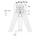
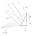
例えば図3に示したように、映像源Pjからは水平方向に41.5°の範囲の投影映像Lpjを出射する。映像偏向部Deには、例えば、投影映像Lpjを水平方向に10°ずつのエリアに分割した4つのエリア映像Lpj1,Lpj2,Lpj3,Lpj4が入射する。映像偏向部Deにおいて、4つのエリア映像Lpj1,Lpj2,Lpj3,Lpj4は、それぞれ4つの曲面ミラーMc1,Mc2,Mc3,Mc4に入射する。4つの曲面ミラーMc1,Mc2,Mc3,Mc4はそれぞれ、4つのエリア映像Lpj1,Lpj2,Lpj3,Lpj4を、それぞれスクリーン2に向けて互いに異なる角度で拡大反射して偏向投影する。曲面ミラーMc1,Mc2,Mc3,Mc4は、4つのエリア映像Lpj1,Lpj2,Lpj3,Lpj4を、例えば、スクリーン2上で水平方向に2°ずつ異なる角度で投影する。これにより、水平方向に2°ずつ視点位置のずれた4つの視点映像を表示することができる。 For example, as shown in FIG. 3, a projected image Lpj within a range of 41.5° in the horizontal direction is emitted from the image source Pj. Four area images Lpj1, Lpj2, Lpj3, and Lpj4 obtained by dividing the projection image Lpj into areas of 10° each in the horizontal direction, for example, enter the image deflection unit De. In the image deflector De, the four area images Lpj1, Lpj2, Lpj3 and Lpj4 are incident on the four curved mirrors Mc1, Mc2, Mc3 and Mc4, respectively. The four curved mirrors Mc1, Mc2, Mc3, and Mc4 respectively magnify and reflect the four area images Lpj1, Lpj2, Lpj3, and Lpj4 toward the
また、映像偏向部Deは、図2に示したように、複数のエリア映像Lpjnのそれぞれの映像中心光線Vcがスクリーン2上で一致するように、複数のエリア映像Lpjnのそれぞれを偏向投影することが望ましい。
Further, as shown in FIG.2 , the image deflector De deflects and projects each of the plurality of area images Lpjn so that the respective image center rays Vc of the plurality of area images Lpjn match on the
また、図4に示したように、映像源Pjと映像偏向部Deは、例えば、スクリーン2に対して下方に配置する。これにより、複数のエリア映像Lpjnを、スクリーン2に対して下側から打ち上げ投影する。 Also, as shown in FIG. 4, the image source Pj and the image deflector De are arranged below the
スクリーン2に対して下側から打ち上げ投影するために、映像偏向部Deにおける曲面ミラーアレイMcを、打ち上げ角度に応じた角度でスクリーン2に対して傾斜するように配置する。また、曲面ミラーアレイMcにおける複数の曲面ミラーMcnはそれぞれ、垂直方向において平面形状とする。 In order to perform launch projection onto the
なお、上述した投影映像Lpjの分割角度やスクリーン2上におけるエリア映像Lpj1,Lpj2,Lpj3,Lpj4の偏向角度の値は一例であって、上述した値に限定されるものではない。 Note that the values of the division angle of the projected image Lpj and the deflection angles of the area images Lpj1, Lpj2, Lpj3, and Lpj4 on the
(変形例)
(第1の変形例)
図5は、側面方向から見た映像表示装置1の第1の変形例の全体構成の一例を示している。(Modification)
(First modification)
FIG. 5 shows an example of the overall configuration of the first modified example of the
第1の変形例に係る映像表示装置1Aは、図4に示した映像表示装置1における映像偏向部De(曲面ミラーアレイMc)に代えて、映像偏向部Dea(曲面ミラーアレイMc′)を備えている。 An image display device 1A according to the first modification includes an image deflection unit Dea (curved mirror array Mc') instead of the image deflection unit De (curved mirror array Mc) in the
図4では、曲面ミラーアレイMcにおける複数の曲面ミラーMcnをそれぞれ、垂直方向において平面形状とした例を示したが、図5に示した曲面ミラーアレイMc′のように、複数の曲面ミラーMcnをそれぞれ、垂直方向においても曲面形状にしてもよい。複数の曲面ミラーMcnを垂直方向においても曲面形状にすることで、エリア映像Lpjnを垂直方向にも拡大投影することができる。 FIG. 4 shows an example in which each of the plurality of curved mirrors Mcn in the curved mirror array Mc has a planar shape in the vertical direction. Each may be curved in the vertical direction as well. By making the plurality of curved mirrors Mcn curved also in the vertical direction, the area image Lpjn can be enlarged and projected also in the vertical direction.
(第2の変形例)
図6は、上面方向から見た第1の実施の形態に係る映像表示装置1の第2の変形例の全体構成の一例を示している。(Second modification)
FIG. 6 shows an example of the overall configuration of the second modification of the
第2の変形例に係る映像表示装置1Bは、図2に示した映像表示装置1における1つの映像源Pjと1つの映像偏向部Deとを1つの組とする映像表示ユニットを、複数組、備えた構成となっている。これにより、複数の映像源Pj1,Pj2,…Pjnと、複数の映像偏向部De1,De2,…Denとを備えた構成となっている。 A
複数の映像源Pj1,Pj2,…Pjnと、複数の映像偏向部De1,De2,…Denとを水平方向に並列的に配列することで、例えば立体映像の視点数と視域を広げることができる。図6には、8つの映像源Pj1,Pj2,…Pj8と、8つの映像偏向部De1,De2,…De8とが配列された構成例を示す。例えば1つの映像源Pjと1つの映像偏向部Deとの組によって、水平方向に2°ずつ視点位置のずれた4つの視点映像を表示するものとすると、図6の構成例では、4×8=32個の視点映像を表示することができる。視域幅としては、
2°(ピッチ)×32(視点)=64°の視域幅が得られる。By arranging a plurality of image sources Pj1, Pj2, . . . Pjn and a plurality of image deflection units De1, De2, . . FIG. 6 shows a configuration example in which eight image sources Pj1, Pj2, . . . Pj8 and eight image deflectors De1, De2, . For example, assuming that a set of one image source Pj and one image deflector De is used to display four viewpoint images whose viewpoint positions are shifted by 2° in the horizontal direction, the configuration example in FIG. = 32 viewpoint images can be displayed. As for the width of the viewing zone,
A viewing zone width of 2° (pitch)×32 (viewpoint)=64° is obtained.
[1.2 効果]
以上のように、本実施の形態によれば、1つの映像源Pjからの投影映像Lpjから分割された複数のエリア映像Lpjnのそれぞれをスクリーン2に向けて互いに異なる角度で偏向投影することによって複数視点の映像表示を行うようにしたので、小型、低コストで多視点の映像表示を行うことが可能となる。[1.2 Effect]
As described above, according to the present embodiment, each of the plurality of area images Lpjn divided from the projection image Lpj from one image source Pj is deflected and projected onto the
図2の構成例では、1つの投影映像Lpjを4つのエリア映像Lpj1,Lpj2,Lpj3,Lpj4に分け、それぞれのエリア映像Lpjnに対応した曲面ミラーMcnによって拡大反射して偏向投影することで、あたかも4つの仮想映像源Vpj(Vpj1,Vpj2,Vpj3,Vpj4)があるように投影することができる。これにより、図1の比較例に係る映像表示装置に比べて、複数視点の映像を表示するために必要な光源(映像源)の数を減らすことができる。また、本実施の形態によれば、映像源Pjからの投影映像Lpjを映像偏向部Deで逆向きにスクリーン2に向けて折り返す構造になっていることで、スクリーン2に対して仮想映像源Vpjを映像偏向部Deよりも外側に位置させることができる。このため、実際に仮想映像源Vpjの位置に映像源Pjを配置する場合よりも、スクリーン2を含めた映像表示装置のサイズを小さくすることができる。 In the configuration example of FIG. 2, one projection image Lpj is divided into four area images Lpj1, Lpj2, Lpj3, and Lpj4, and the curved mirrors Mcn corresponding to the area images Lpjn magnify and reflect each of the area images Lpjn for deflection projection. It can be projected such that there are four virtual image sources Vpj (Vpj1, Vpj2, Vpj3, Vpj4). As a result, the number of light sources (image sources) required for displaying images from multiple viewpoints can be reduced compared to the image display device according to the comparative example of FIG. Further, according to the present embodiment, the projection image Lpj from the image source Pj is reversed toward the
なお、本明細書に記載された効果はあくまでも例示であって限定されるものではなく、また他の効果があってもよい。以降の他の実施の形態の効果についても同様である。 Note that the effects described in this specification are merely examples and are not limited, and other effects may also occur. The same applies to the effects of other embodiments described below.
<2.第2の実施の形態>
次に、本開示の第2の実施の形態に係る映像表示装置について説明する。なお、以下では、上記第1の実施の形態に係る映像表示装置の構成要素と略同じ部分については、同一符号を付し、適宜説明を省略する。<2. Second Embodiment>
Next, a video display device according to a second embodiment of the present disclosure will be described. It should be noted that, hereinafter, the same reference numerals are assigned to substantially the same components as those of the image display device according to the first embodiment, and the description thereof will be omitted as appropriate.
図7および図8は、第2の実施の形態に係る映像表示装置1Cの一構成例を示している。図7は、上面方向から見た映像表示装置1Cの全体構成の一例を示している。図8は、側面方向から見た映像表示装置1Cの一構成例を概略的に示している。 7 and 8 show a configuration example of a
第1の実施の形態に係る映像表示装置1(図2、図4)では、平面型のスクリーン2を用いる構成例を示したが、第2の実施の形態に係る映像表示装置1Cは、円筒型のスクリーン2Aを用いた構成となっている。 In the video display device 1 (FIGS. 2 and 4) according to the first embodiment, a configuration example using the
円筒型のスクリーン2Aは、水平方向と垂直方向とで光拡散特性が異なる透過型または反射型の異方性拡散特性を持つ略半円筒のスクリーンである。円筒型のスクリーン2Aは、例えば、異方性拡散板である。円筒型のスクリーン2Aは、水平方向と垂直方向とで光拡散特性が異なる異方性拡散特性を持つ回折素子であってもよい。回折素子は、HOEであってもよい。円筒型のスクリーン2Aの異方性拡散特性は、例えば水平方向は相対的に狭拡散、垂直方向は相対的に広拡散であることが望ましい。水平方向は狭拡散とすることで、異なる角度から投影される複数の視点映像が不必要に混じり合うことを抑制することができる。 The
第2の実施の形態に係る映像表示装置1Cでは、複数のエリア映像Lpjnのそれぞれの映像中心光線Vcが円筒型のスクリーン2Aの円筒軸C1を通過するように、複数のエリア映像Lpjnのそれぞれを偏向投影することが望ましい。これにより、円筒型のスクリーン2Aの投影面(円筒面)上では、複数のエリア映像Lpjnのそれぞれの映像中心光線Vcが同一のずれ角で少しずつずれた状態で偏向投影される。これにより、円筒型のスクリーン2Aの円筒面上では、複数のエリア映像Lpjnのそれぞれが同一のずれ角で少しずつずれた状態で重ね合わさるように偏向投影される。 In the
その他の構成、動作および効果は、上記第1の実施の形態に係る映像表示装置と略同様であってもよい。 Other configurations, operations, and effects may be substantially the same as those of the image display device according to the first embodiment.
(変形例)
(第1の変形例)
図9は、側面方向から見た第2の実施の形態に係る映像表示装置1Cの第1の変形例を概略的に示している。(Modification)
(First modification)
FIG. 9 schematically shows a first modification of the
図9に示したように、円筒型のスクリーン2Aに対して上側に反射ミラー3を配置し、映像偏向部Deからの複数のエリア映像Lpjnを上側の反射ミラー3で一旦反射させた後、反射ミラー3から下側に向けて円筒型のスクリーン2Aに投影してもよい。 As shown in FIG. 9, a reflecting
特に、円筒型のスクリーン2Aが透過型のHOEである場合、観察方向Z1とは反対側のスクリーン面からの外光Lexの影響が課題となる。スクリーン2AがHOEの場合、図9のように一旦、複数のエリア映像Lpjnを上側に投影して反射ミラー3で反射させてから、スクリーン2Aに打ち下ろすように投影することにより、外光Lex自体が入りにくくなり、外光Lexの影響を受けにくくすることができる。これにより、外光耐性が向上する。 In particular, when the
(第2の変形例)
図10は、上面方向から見た第2の実施の形態に係る映像表示装置1Cの第2の変形例の全体構成の一例を示している。(Second modification)
FIG. 10 shows an example of the overall configuration of the second modification of the
第2の変形例に係る映像表示装置1Dは、図7に示した映像表示装置1Cにおける1つの映像源Pjと1つの映像偏向部Deとを1つの組とする映像表示ユニットを、複数組、備えた構成となっている。これにより、複数の映像源Pj1,Pj2,…Pjnと、複数の映像偏向部De1,De2,…Denとを備えた構成となっている。 A
第2の変形例に係る映像表示装置1Dでは、投影面が360°の完全な円筒スクリーン2Bに向けて、複数のエリア映像Lpjnを投影する。環状に複数の映像源Pj1,Pj2,…Pjnと複数の映像偏向部De1,De2,…Denとを配置することで、360°の円筒スクリーン2Bに複数のエリア映像Lpjnを投影する。これにより、360°の多視点の映像が得られる。 In the
<3.第3の実施の形態>
次に、本開示の第3の実施の形態に係る映像表示装置について説明する。なお、以下では、上記第1または第2の実施の形態に係る映像表示装置の構成要素と略同じ部分については、同一符号を付し、適宜説明を省略する。<3. Third Embodiment>
Next, a video display device according to a third embodiment of the present disclosure will be described. In the following description, the same reference numerals are assigned to substantially the same components as those of the image display device according to the first or second embodiment, and description thereof will be omitted as appropriate.
上記第1および第2の実施の形態に係る映像表示装置における映像偏向部Deは、図11~図14に示す構成であってもよい。 The image deflector De in the image display apparatuses according to the first and second embodiments may have the configurations shown in FIGS. 11 to 14. FIG.
(第1の構成例)
図11は、上面方向から見た映像偏向部Deの第1の構成例を示している。(First configuration example)
FIG. 11 shows a first configuration example of the image deflection unit De viewed from above.
映像偏向部Deは、水平方向に配列された複数の曲面ミラーMcnを有する曲面ミラーアレイMcであってもよい。複数の曲面ミラーMcnは、それぞれ少なくとも水平方向において曲面形状である。図11では、曲面ミラーMcnが水平方向に凸面形状(凸面ミラー)である例を示しているが、曲面ミラーMcnが水平方向に凹面形状(凹面ミラー)であってもよい。凹面ミラーの方が、拡大倍率を高くとりやすい。図11には、映像偏向部Deの曲面ミラーアレイMcが4つの曲面ミラーMc1,Mc2,Mc3,Mc4を有する例を示しているが、複数の曲面ミラーMcnの数は、4つに限らず、5つ以上、または2つや3つであってもよい。曲面ミラーアレイMcを構成する曲面ミラーMcnの数を、生成するエリア映像Lpjn(視点映像)の数に応じた数だけ設ければよい。また、曲面ミラーアレイMcは、垂直方向において平面形状(図4参照)であってもよいし、垂直方向において拡大投影する場合には垂直方向において曲面形状(図5参照)であってもよい。 The image deflector De may be a curved mirror array Mc having a plurality of curved mirrors Mcn arranged in the horizontal direction. Each of the plurality of curved mirrors Mcn has a curved shape at least in the horizontal direction. Although FIG. 11 shows an example in which the curved mirror Mcn is horizontally convex (convex mirror), the curved mirror Mcn may be horizontally concave (concave mirror). A concave mirror is easier to obtain a higher magnification. FIG. 11 shows an example in which the curved mirror array Mc of the image deflection unit De has four curved mirrors Mc1, Mc2, Mc3, and Mc4, but the number of curved mirrors Mcn is not limited to four. It may be 5 or more, or 2 or 3. The number of curved mirrors Mcn constituting the curved mirror array Mc may be provided in accordance with the number of area images Lpjn (viewpoint images) to be generated. The curved mirror array Mc may have a flat shape in the vertical direction (see FIG. 4), or may have a curved shape in the vertical direction (see FIG. 5) in the case of enlarged projection in the vertical direction.
(第2の構成例)
図12は、上面方向から見た映像偏向部Deの第2の構成例を示している。(Second configuration example)
FIG. 12 shows a second configuration example of the image deflection unit De viewed from above.
映像偏向部Deは、曲面ミラーアレイMcと拡大レンズLaとを含む構成であってもよい。曲面ミラーアレイMcの構成は、図11と略同様であってもよい。拡大レンズLaは、映像源Pjと曲面ミラーアレイMcとの間に配置されている。拡大レンズLaは、少なくとも水平方向において光の拡大作用を有している。映像源Pjからの投影映像Lpjを拡大レンズLaで拡大した後、曲面ミラーアレイMc入射させる構成であってもよい。 The image deflector De may be configured to include a curved mirror array Mc and a magnifying lens La. The configuration of the curved mirror array Mc may be substantially the same as in FIG. A magnifying lens La is arranged between the image source Pj and the curved mirror array Mc. The magnifying lens La has a light magnifying effect at least in the horizontal direction. A configuration may be employed in which the projected image Lpj from the image source Pj is magnified by the magnifying lens La and then incident on the curved mirror array Mc.
(第3の構成例)
図13は、上面方向から見た映像偏向部Deの第3の構成例を示している。(Third configuration example)
FIG. 13 shows a third configuration example of the image deflector De viewed from above.
映像偏向部Deは、平面ミラーアレイMpと拡大レンズLaとを含む構成であってもよい。平面ミラーアレイMpは、水平方向に配列された複数の平面ミラーMpnを有する。複数の平面ミラーMpnは、それぞれ少なくとも水平方向において平面形状である。平面ミラーアレイMpは、水平方向には拡大作用を有しないが、偏向作用を有する。複数の平面ミラーMpnはそれぞれ、複数のエリア映像Lpjnを互いに異なる方向に偏向投影するように、互いに別々の角度で配置されている。この構成の場合、映像偏向部Deの水平方向における拡大作用は、拡大レンズLaが担う。図13には、映像偏向部Deの平面ミラーアレイMpが4つの平面ミラーMp1,Mp2,Mp3,Mp4を有する例を示しているが、複数の複数の平面ミラーMpnの数は、4つに限らず、5つ以上、または2つや3つであってもよい。平面ミラーアレイMpを構成する複数の平面ミラーMpnの数を、生成するエリア映像Lpjn(視点映像)の数に応じた数だけ設ければよい。 The image deflector De may be configured to include a plane mirror array Mp and a magnifying lens La. The plane mirror array Mp has a plurality of plane mirrors Mpn arranged in the horizontal direction. Each of the plurality of plane mirrors Mpn has a planar shape at least in the horizontal direction. The plane mirror array Mp does not have a magnifying action in the horizontal direction, but has a deflecting action. The plane mirrors Mpn are arranged at different angles so as to deflect and project the area images Lpjn in different directions. In the case of this configuration, the magnifying lens La is responsible for the magnifying action in the horizontal direction of the image deflection section De. FIG. 13 shows an example in which the plane mirror array Mp of the image deflector De has four plane mirrors Mp1, Mp2, Mp3, and Mp4, but the number of plane mirrors Mpn is limited to four. The number may be five or more, or two or three. The number of plane mirrors Mpn constituting the plane mirror array Mp may be set according to the number of area images Lpjn (viewpoint images) to be generated.
(第4の構成例)
図14は、上面方向から見た映像偏向部Deの第4の構成例を示している。(Fourth configuration example)
FIG. 14 shows a fourth configuration example of the image deflector De viewed from above.
映像偏向部Deは、水平方向に配列された複数の回折領域Hanを有する回折素子アレイHaを含む構成であってもよい。複数の回折領域Hanは、それぞれ少なくとも水平方向において拡大作用および偏向作用を有している。図14には、映像偏向部Deの回折領域Hanが4つの回折領域Ha1,Ha2,Ha3,Ha4を有する例を示しているが、複数の回折領域Hanの数は、4つに限らず、5つ以上、または2つや3つであってもよい。回折素子アレイHaにおける回折領域Hanの数を、生成するエリア映像Lpjn(視点映像)の数に応じた数だけ設ければよい。また、回折素子アレイHaは、垂直方向において拡大作用を有しない構成であってもよいし、垂直方向において拡大作用を有する構成であってもよい。 The image deflection section De may be configured to include a diffraction element array Ha having a plurality of diffraction areas Han arranged in the horizontal direction. Each of the plurality of diffraction areas Han has a magnifying action and a deflecting action at least in the horizontal direction. FIG. 14 shows an example in which the diffraction area Han of the image deflector De has four diffraction areas Ha1, Ha2, Ha3, and Ha4. It may be one or more, or two or three. The number of diffraction regions Han in the diffraction element array Ha should be set according to the number of area images Lpjn (viewpoint images) to be generated. Moreover, the diffraction element array Ha may be configured to have no magnifying action in the vertical direction, or may have a magnifying action in the vertical direction.
また、映像偏向部Deは、図12の構成例と同様に、回折素子アレイHaに加えて拡大レンズLaを含む構成であってもよい。また、図14では、複数の回折領域Hanが反射作用を有する反射型の回折素子アレイHaである構成例を示しているが、複数の回折領域Hanが透過作用を有する透過型の回折素子アレイであってもよい。映像偏向部Deに、透過型の回折素子アレイを用いる場合、複数のエリア映像Lpjnの投影方向およびスクリーン2等の配置位置は、これまでの構成例とは逆側(図14の上側)となる。 Further, the image deflector De may be configured to include a magnifying lens La in addition to the diffraction element array Ha, as in the configuration example of FIG. Further, FIG. 14 shows a configuration example in which the plurality of diffraction areas Han is a reflective diffraction element array Ha having a reflecting action. There may be. When a transmissive diffraction element array is used for the image deflection unit De, the projection direction of the plurality of area images Lpjn and the arrangement positions of the
その他の構成、動作および効果は、上記第1または第2の実施の形態に係る映像表示装置と略同様であってもよい。 Other configurations, operations and effects may be substantially the same as those of the image display device according to the first or second embodiment.
<4.第4の実施の形態>
次に、本開示の第4の実施の形態に係る映像表示装置について説明する。なお、以下では、上記第1ないし第3のいずれかの実施の形態に係る映像表示装置の構成要素と略同じ部分については、同一符号を付し、適宜説明を省略する。<4. Fourth Embodiment>
Next, a video display device according to a fourth embodiment of the present disclosure will be described. In the following description, substantially the same components as those of the image display device according to any one of the first to third embodiments are denoted by the same reference numerals, and description thereof will be omitted as appropriate.
上記第1ないし第3の実施の形態では、映像偏向部Deが、垂直方向に1つの曲面ミラーアレイMc等を備えた1段のアレイ構成とされていたが、垂直方向に複数のアレイを配列した複数段のアレイ構成であってもよい。垂直方向に複数のアレイを配列することで、垂直方向の視域を拡大したり垂直方向に視点数を増やすことができる(図15、図16参照)。また、水平方向にも視点数を増やし、水平方向の解像度を向上させることができる(図17参照) In the first to third embodiments, the image deflector De has a one-stage array configuration including one curved mirror array Mc or the like in the vertical direction, but a plurality of arrays are arranged in the vertical direction. A multi-stage array configuration may also be used. By arranging a plurality of arrays in the vertical direction, it is possible to expand the viewing area in the vertical direction and increase the number of viewpoints in the vertical direction (see FIGS. 15 and 16). Also, the number of viewpoints can be increased in the horizontal direction, and the resolution in the horizontal direction can be improved (see FIG. 17).
以下、図15ないし図17に、曲面ミラーアレイMcを垂直方向に2段配置した構成例を示すが、垂直方向に3段以上配置したアレイ構成にしてもよい。また、曲面ミラーアレイMcにおける複数の曲面ミラーMcnが水平方向に凸面形状(凸面ミラー)である例を示すが、曲面ミラーMcnが水平方向に凹面形状(凹面ミラー)であってもよい。また、曲面ミラーアレイMcに代えて、平面ミラーアレイMp(図13参照)や回折素子アレイHa(図14参照)を垂直方向に複数段、配置したアレイ構成にしてもよい。また、以下では1つの曲面ミラーアレイMcが垂直方向に平面形状である構成例を示すが、垂直方向においても曲面形状にしてもよい(図5参照)。 15 to 17 show configuration examples in which curved mirror arrays Mc are arranged in two stages in the vertical direction, but an array configuration in which curved mirror arrays Mc are arranged in three or more stages in the vertical direction may be employed. Further, although an example in which the plurality of curved mirrors Mcn in the curved mirror array Mc are horizontally convex (convex mirrors) is shown, the curved mirrors Mcn may be horizontally concave (concave mirrors). Further, instead of the curved mirror array Mc, an array configuration in which a plurality of plane mirror arrays Mp (see FIG. 13) and diffraction element arrays Ha (see FIG. 14) are arranged in the vertical direction may be employed. In the following, a configuration example in which one curved mirror array Mc has a planar shape in the vertical direction will be shown, but it may also have a curved shape in the vertical direction (see FIG. 5).
(第1の構成例)
図15は、第4の実施の形態の第1の構成例に係る映像表示装置1Eにおける上面方向および側面方向から見た構成を示している。図16は、図15に示した映像偏向部Deを側面方向から拡大して示したものである。(First configuration example)
FIG. 15 shows the configuration of the
第1の構成例に係る映像表示装置1Eは、映像偏向部Deが、垂直方向に異なる位置に配置された2つの曲面ミラーアレイMca,Mcbを有している。図15の右上の上面図に示したように、曲面ミラーアレイMcaは、水平方向に配列された複数の曲面ミラーMcanを有している。同様に、曲面ミラーアレイMcbは、水平方向に配列された複数の曲面ミラーMcabを有している。図15の右上の上面図に示したように、曲面ミラーアレイMcaにおける複数の曲面ミラーMcanのそれぞれと、曲面ミラーアレイMcbにおける複数の曲面ミラーMcbnのそれぞれとが、水平方向において互いに同一位置となるように配列されている。曲面ミラーアレイMca,Mcbを傾けて配置する場合、各曲面ミラーMcan,Mcbnに投影される投影映像Lpjの範囲は射影で扇形形状になる。このため、その広がりを考慮して、下側の曲面ミラーMcanに対して上側の曲面ミラーMcbnは大きくしてもよい。この場合、水平位置が拡大した分、水平方向における下側の曲面ミラーMcanと上側の曲面ミラーMcbnとの配列が拡大した比率分、ずれてもよい(投影画角に対する角度位置が一致していればよい)。 In the
2つの曲面ミラーアレイMca,Mcbは、垂直方向において互いに異なる傾斜角度で傾斜配置されてもよい。これにより、曲面ミラーアレイMcaによって偏向投影する投影映像(投影光)Lpjaと、曲面ミラーアレイMcbによって偏向投影する投影映像(投影光)Lpjbとの偏向角度を異ならせ、垂直方向の視域を拡大することができる。 The two curved mirror arrays Mca and Mcb may be tilted at different tilt angles in the vertical direction. As a result, the deflection angles of the projected image (projection light) Lpja deflected and projected by the curved mirror array Mca and the projected image (projection light) Lpjb deflected and projected by the curved mirror array Mcb are varied to expand the viewing zone in the vertical direction. can do.
(第2の構成例)
図17は、第4の実施の形態の第2の構成例に係る映像表示装置1Fにおける上面方向および側面方向から見た構成を示している。(Second configuration example)
FIG. 17 shows the configuration of the
第2の構成例に係る映像表示装置1Fは、第1の構成例に係る映像表示装置1Eと同様に、映像偏向部Deが、垂直方向に異なる位置に配置された2つの曲面ミラーアレイMca,Mcbを有している。第2の構成例に係る映像表示装置1Fは、第1の構成例に係る映像表示装置1Eに対して、2つの曲面ミラーアレイMca,Mcbの水平方向の配置位置が異なっている。第2の構成例に係る映像表示装置1Fでは、図17の右上の上面図に示したように、曲面ミラーアレイMcaにおける複数の曲面ミラーMcanのそれぞれと、曲面ミラーアレイMcbにおける複数の曲面ミラーMcbnのそれぞれとが、水平方向において互いに異なる(互い違いに)なるように配列されている。これにより、水平方向にも視点数を増やし、水平方向の解像度を向上させることができる。 In the
第2の構成例に係る映像表示装置1Fにおける映像偏向部Deの垂直方向の構成は第1の構成例(図16)と略同様であってもよい。 The configuration in the vertical direction of the image deflector De in the
その他の構成、動作および効果は、上記第1ないし第3の実施の形態に係る映像表示装置と略同様であってもよい。 Other configurations, operations and effects may be substantially the same as those of the image display devices according to the first to third embodiments.
<5.第5の実施の形態>
次に、本開示の第5の実施の形態に係る映像表示装置について説明する。なお、以下では、上記第1ないし第4のいずれかの実施の形態に係る映像表示装置の構成要素と略同じ部分については、同一符号を付し、適宜説明を省略する。<5. Fifth Embodiment>
Next, a video display device according to a fifth embodiment of the present disclosure will be described. In the following description, substantially the same components as those of the image display device according to any one of the first to fourth embodiments are denoted by the same reference numerals, and description thereof will be omitted as appropriate.
図18は、上面方向から見た第5の実施の形態に係る映像表示装置における映像源Pjの一構成例を示している。 FIG. 18 shows a configuration example of the image source Pj in the image display device according to the fifth embodiment viewed from above.
上記第1の実施の形態において説明したように、本開示の技術における映像源Pjは、例えば、LCOS型のプロジェクタ、DMD型のMEMSプロジェクタ、またはシングルミラー型のMEMSプロジェクタ等で構成することができる。さらに、図18に示したように、映像源Pjが、投影映像Lpjを単一の走査ミラーに入射した角度の異なる複数のレーザ光を走査することによって生成する走査型プロジェクタであってもよい。 As described in the first embodiment, the image source Pj in the technique of the present disclosure can be configured by, for example, an LCOS type projector, a DMD type MEMS projector, or a single mirror type MEMS projector. . Furthermore, as shown in FIG. 18, the image source Pj may be a scanning projector that generates a projection image Lpj by scanning a plurality of laser beams incident on a single scanning mirror at different angles.
図18に示した映像源Pjは、単一の走査ミラーであるMEMSミラー11と、レーザ光源となる、端面レーザアレイまたはVCSEL(Vertical Cavity Surface Emitting Laser)12と、集光レンズ13とを備えている。 The image source Pj shown in FIG. 18 is equipped with a
VCSEL12は、複数のレーザ光を出力する面発光半導体レーザである。集光レンズ13は、VCSEL12から出力された複数のレーザ光を、互いに異なる角度でMEMSミラー11に向けて集光する。MEMSミラー11は、例えば、ミラー面を2つの軸を中心に傾けることが可能な2軸の可動ミラーである。 The
図18に示した映像源Pjのように、単一の走査ミラーであるMEMSミラー11に複数のレーザ光を角度を変えて入射し、複数のエリア映像Lpjnを複数のレーザ光のそれぞれで分担してスキャン投影するような走査型プロジェクタであってもよい。これにより、映像源Pjの画角が広がることで、図1の比較例に係る映像表示装置に比べて、複数視点の映像を表示するために必要な光源(映像源)の数をさらに減らすことができる。 Like the image source Pj shown in FIG. 18, a plurality of laser beams are incident on the
図18に示した映像源Pjの構成によれば、単一の走査ミラーに複数のレーザ光を角度を変えて入射し、走査することで広角化を行うとともに、レーザ変調周波数を保ったままでも高解像度化ができる。 According to the configuration of the image source Pj shown in FIG. 18, a plurality of laser beams are incident on a single scanning mirror at different angles to widen the angle by scanning, while maintaining the laser modulation frequency. High resolution is possible.
例えば図18に示したように、映像源Pjからは水平方向に83.5°の範囲の投影映像Lpjを出射する。映像偏向部Deには、例えば、投影映像Lpjを水平方向に20.5°ずつのエリアに分割した4つのエリア映像Lpj1,Lpj2,Lpj3,Lpj4が入射する。 For example, as shown in FIG. 18, a projection image Lpj within a range of 83.5° in the horizontal direction is emitted from the image source Pj. For example, four area images Lpj1, Lpj2, Lpj3, and Lpj4 obtained by dividing the projection image Lpj into areas of 20.5 degrees in the horizontal direction are incident on the image deflection unit De.
なお、図18では、1つのレーザ光によって1つのエリア映像Lpjnを偏向投影するようにMEMSミラー11を制御しているが、1つのレーザ光によって2以上のエリア映像Lpjnを偏向投影するようにMEMSミラー11を制御してもよい。 In FIG. 18, the
その他の構成、動作および効果は、上記第1ないし第4の実施の形態に係る映像表示装置と略同様であってもよい。 Other configurations, operations and effects may be substantially the same as those of the image display devices according to the first to fourth embodiments.
<6.その他の実施の形態>
本開示による技術は、上記各実施の形態の説明に限定されず種々の変形実施が可能である。<6. Other Embodiments>
The technology according to the present disclosure is not limited to the description of the above embodiments, and various modifications are possible.
例えば、上記各実施の形態では、映像偏向部が水平方向に拡大作用を有する場合を例にしたが、映像偏向部が水平方向に拡大作用を有しない構成であっても良い。例えば、図11に示した映像偏向部Deの構成に対して、曲面ミラーMcnを水平方向に平面形状にし、映像偏向部Deが水平方向には偏向作用のみを有する構成にしてもよい。また、例えば、図14に示した映像偏向部Deの構成に対して、回折領域Hanが水平方向には拡大作用がなく、偏向作用のみを有する構成にしてもよい。 For example, in each of the above-described embodiments, the image deflection section has a horizontal enlargement action, but the image deflection section may not have a horizontal enlargement action. For example, in contrast to the configuration of the image deflecting section De shown in FIG. 11, the curved mirror Mcn may be made flat in the horizontal direction, and the image deflecting section De may have only the deflection action in the horizontal direction. Further, for example, in contrast to the configuration of the image deflection section De shown in FIG. 14, the diffraction area Han may have a configuration in which it has only a deflection action without an enlargement action in the horizontal direction.
例えば、本技術は以下のような構成を取ることもできる。
以下の構成の本技術によれば、映像源からの投影映像から分割された複数のエリア映像のそれぞれをスクリーンに向けて互いに異なる角度で偏向投影することによって複数視点の映像表示を行うようにしたので、小型、低コストで多視点の映像表示を行うことが可能となる。
(1)
2次元的な投影映像を出射する少なくとも1つの映像源と、
前記映像源からの前記投影映像を少なくとも水平方向の複数のエリアに分割して複数のエリア映像を生成し、前記複数のエリア映像が異方性拡散特性を持つスクリーン上で部分的に重ね合わさることで複数視点の映像表示が行われるように、前記複数のエリア映像をそれぞれ前記スクリーンに向けて互いに異なる角度で偏向投影する、少なくとも1つの映像偏向部と
を備える
映像表示装置。
(2)
前記映像偏向部は、前記複数のエリア映像をそれぞれ前記スクリーンに向けて互いに異なる角度で拡大して偏向投影する
上記(1)に記載の映像表示装置。
(3)
前記映像偏向部は、
水平方向に配列された複数のミラーを有する少なくとも1つのミラーアレイを含み、
前記複数のミラーはそれぞれ水平方向において曲面形状または平面形状である
上記(1)または(2)に記載の映像表示装置。
(4)
前記複数のミラーはそれぞれ、水平方向において曲面形状であり、垂直方向において平面形状または曲面形状である
上記(3)に記載の映像表示装置。
(5)
前記映像偏向部は、前記ミラーアレイを複数、含み、
前記複数のミラーアレイは、垂直方向に配列されている
上記(3)または(4)に記載の映像表示装置。
(6)
垂直方向に異なる位置にある前記複数のミラーアレイ同士の前記複数のミラーの配列が、水平方向において互いに同一である
上記(5)に記載の映像表示装置。
(7)
垂直方向に異なる位置にある前記複数のミラーアレイ同士の前記複数のミラーの配列が、水平方向において互いに異なる
上記(5)に記載の映像表示装置。
(8)
前記映像偏向部は、
水平方向に配列された複数のミラーを有するミラーアレイと、
前記映像源と前記ミラーアレイとの間に配置された拡大レンズと
を含む
上記(2)に記載の映像表示装置。
(9)
前記複数のミラーはそれぞれ、水平方向において平面形状または曲面形状であり、垂直方向において平面形状または曲面形状である
上記(8)に記載の映像表示装置。
(10)
前記映像偏向部は、
水平方向に配列された複数の回折領域を有する回折素子を含み、
前記複数の回折領域はそれぞれ少なくとも水平方向において偏向作用を有する
上記(1)または(2)に記載の映像表示装置。
(11)
前記映像源は、前記投影映像を反射型液晶素子によって生成する液晶プロジェクタである
上記(1)ないし(10)のいずれか1つに記載の映像表示装置。
(12)
前記映像源は、前記投影映像を2次元配列された複数の可動ミラーによって生成するプロジェクタである
上記(1)ないし(10)のいずれか1つに記載の映像表示装置。
(13)
前記映像源は、前記投影映像を単一の走査ミラーによって生成する走査型プロジェクタである
上記(1)ないし(10)のいずれか1つに記載の映像表示装置。
(14)
前記映像源は、前記投影映像を前記単一の走査ミラーに入射した角度の異なる複数のレーザ光を走査することによって生成する走査型プロジェクタである
上記(13)に記載の映像表示装置。
(15)
1つの前記映像源と1つの前記映像偏向部とを1つの組とする映像表示ユニットを、複数組、備えた
上記(1)ないし(14)のいずれか1つに記載の映像表示装置。
(16)
前記スクリーンは、水平方向と垂直方向とで光拡散特性が異なる透過型または反射型の異方性拡散特性を持つ平面スクリーンである
上記(1)ないし(15)のいずれか1つに記載の映像表示装置。
(17)
前記スクリーンは、水平方向と垂直方向とで光拡散特性が異なる透過型または反射型の異方性拡散特性を持つ円筒スクリーンである
上記(1)ないし(15)のいずれか1つに記載の映像表示装置。
(18)
前記スクリーンは、水平方向と垂直方向とで光拡散特性が異なる異方性拡散板である
上記(1)ないし(17)のいずれか1つに記載の映像表示装置。
(19)
前記スクリーンは、水平方向と垂直方向とで光拡散特性が異なる異方性拡散特性を持つ回折素子である
上記(1)ないし(17)のいずれか1つに記載の映像表示装置。
(20)
前記映像源は、前記スクリーンと前記映像偏向部との間に配置されている
上記(1)ないし(19)のいずれか1つに記載の映像表示装置。For example, the present technology can also have the following configuration.
According to the present technology with the following configuration, a plurality of area images divided from the projection image from the image source are deflected and projected onto the screen at different angles to display images from multiple viewpoints. Therefore, it is possible to perform multi-viewpoint video display in a small size and at low cost.
(1)
at least one image source that emits a two-dimensional projection image;
dividing the projected image from the image source into at least a plurality of horizontal areas to generate a plurality of area images, the plurality of area images being partially superimposed on a screen having anisotropic diffusion properties. and at least one image deflection unit that deflects and projects the plurality of area images toward the screen at different angles so that image display from a plurality of viewpoints is performed in the image display device.
(2)
The image display device according to (1), wherein the image deflection unit enlarges and deflects and projects the plurality of area images toward the screen at different angles.
(3)
The image deflection unit
at least one mirror array having a plurality of horizontally arranged mirrors;
The image display device according to (1) or (2) above, wherein each of the plurality of mirrors has a curved surface shape or a planar shape in the horizontal direction.
(4)
The image display device according to (3), wherein each of the plurality of mirrors has a curved shape in the horizontal direction and a plane shape or a curved shape in the vertical direction.
(5)
the image deflection unit includes a plurality of the mirror arrays,
The video display device according to (3) or (4), wherein the plurality of mirror arrays are arranged in a vertical direction.
(6)
The image display device according to (5) above, wherein the plurality of mirror arrays located at different positions in the vertical direction have the same arrangement of the mirrors in the horizontal direction.
(7)
The image display device according to (5) above, wherein the arrangement of the plurality of mirrors in the plurality of mirror arrays located at different positions in the vertical direction is different in the horizontal direction.
(8)
The image deflection unit
a mirror array having a plurality of horizontally arranged mirrors;
The image display device according to (2) above, further comprising: a magnifying lens arranged between the image source and the mirror array.
(9)
The image display device according to (8) above, wherein each of the plurality of mirrors has a planar shape or a curved shape in the horizontal direction, and a planar shape or a curved shape in the vertical direction.
(10)
The image deflection unit
comprising a diffraction element having a plurality of diffraction regions arranged in a horizontal direction;
The image display device according to (1) or (2) above, wherein each of the plurality of diffraction regions has a deflection action at least in the horizontal direction.
(11)
The image display device according to any one of (1) to (10) above, wherein the image source is a liquid crystal projector that generates the projected image using a reflective liquid crystal element.
(12)
The image display device according to any one of (1) to (10) above, wherein the image source is a projector that generates the projected image by a plurality of movable mirrors arranged two-dimensionally.
(13)
The image display device according to any one of (1) to (10) above, wherein the image source is a scanning projector that generates the projected image using a single scanning mirror.
(14)
The image display device according to (13) above, wherein the image source is a scanning projector that generates the projection image by scanning a plurality of laser beams incident on the single scanning mirror and having different angles.
(15)
The image display device according to any one of (1) to (14) above, comprising a plurality of sets of image display units each including one image source and one image deflection section.
(16)
The image according to any one of (1) to (15) above, wherein the screen is a flat screen having transmissive or reflective anisotropic diffusion characteristics in which light diffusion characteristics are different in the horizontal direction and in the vertical direction. display device.
(17)
The image according to any one of (1) to (15) above, wherein the screen is a cylindrical screen having transmissive or reflective anisotropic diffusion characteristics in which light diffusion characteristics are different in the horizontal direction and in the vertical direction. display device.
(18)
The image display device according to any one of (1) to (17) above, wherein the screen is an anisotropic diffusion plate having different light diffusion characteristics in the horizontal direction and in the vertical direction.
(19)
The image display device according to any one of (1) to (17) above, wherein the screen is a diffraction element having an anisotropic diffusion characteristic with different light diffusion characteristics in the horizontal direction and in the vertical direction.
(20)
The image display device according to any one of (1) to (19) above, wherein the image source is arranged between the screen and the image deflection section.
本出願は、日本国特許庁において2018年4月25日に出願された日本特許出願番号第2018-083669号を基礎として優先権を主張するものであり、この出願のすべての内容を参照によって本出願に援用する。 This application claims priority based on Japanese Patent Application No. 2018-083669 filed on April 25, 2018 at the Japan Patent Office, and the entire contents of this application are incorporated herein by reference. incorporated into the application.
当業者であれば、設計上の要件や他の要因に応じて、種々の修正、コンビネーション、サブコンビネーション、および変更を想到し得るが、それらは添付の請求の範囲やその均等物の範囲に含まれるものであることが理解される。 Depending on design requirements and other factors, those skilled in the art may conceive various modifications, combinations, subcombinations, and modifications that fall within the scope of the appended claims and their equivalents. It is understood that
Claims (20)
Translated fromJapanese前記映像源からの前記投影映像を少なくとも水平方向の複数のエリアに分割して複数のエリア映像を生成し、前記複数のエリア映像が異方性拡散特性を持つスクリーン上で部分的に重ね合わさることで複数視点の映像表示が行われるように、前記複数のエリア映像をそれぞれ前記スクリーンに向けて互いに異なる角度で偏向投影する、少なくとも1つの映像偏向部と
を備え、
前記スクリーンは、円筒スクリーンであり、
前記映像偏向部は、前記複数のエリア映像のそれぞれの映像中心光線が前記円筒スクリーンの円筒軸を通過するように、前記複数のエリア映像のそれぞれを前記円筒スクリーンに向けて偏向投影する
映像表示装置。at least one image source for emittinga projection image ;
dividing the projected image from the image source into at least a plurality of horizontal areas to generate a plurality of area images, the plurality of area images being partially superimposed on a screen having anisotropic diffusion properties. at least one image deflection unit that deflects and projects the plurality of area images toward the screen at different angles so that image display from a plurality of viewpoints is performedin
The screen is a cylindrical screen,
The image deflection unit deflects and projects each of the plurality of area images toward the cylindrical screen such that the image center ray of each of the plurality of area images passes through the cylindrical axis of the cylindrical screen.
video display device.
請求項1に記載の映像表示装置。2. The image display device according to claim 1, wherein the image deflection unit enlarges and deflects and projects the plurality of area images toward the screen at different angles.
水平方向に配列された複数のミラーを有する少なくとも1つのミラーアレイを含み、
前記複数のミラーはそれぞれ水平方向において曲面形状または平面形状である
請求項1に記載の映像表示装置。The image deflection unit
at least one mirror array having a plurality of horizontally arranged mirrors;
The image display device according to claim 1, wherein each of the plurality of mirrors has a curved surface shape or a planar shape in the horizontal direction.
請求項3に記載の映像表示装置。4. The image display device according to claim 3, wherein each of the plurality of mirrors has a curved surface shape in the horizontal direction, and a plane shape or a curved surface shape in the vertical direction.
前記複数のミラーアレイは、垂直方向に配列されている
請求項3に記載の映像表示装置。the image deflection unit includes a plurality of the mirror arrays,
The image display device according to Claim 3, wherein the plurality of mirror arrays are arranged in a vertical direction.
請求項5に記載の映像表示装置。6. The image display device according to claim 5, wherein the arrangement of the plurality of mirrors in the plurality of mirror arrays located at different positions in the vertical direction is the same in the horizontal direction.
請求項5に記載の映像表示装置。6. The image display device according to claim 5, wherein the arrangement of the plurality of mirrors in the plurality of mirror arrays located at different positions in the vertical direction is different from each other in the horizontal direction.
水平方向に配列された複数のミラーを有するミラーアレイと、
前記映像源と前記ミラーアレイとの間に配置された拡大レンズと
を含む
請求項2に記載の映像表示装置。The image deflection unit
a mirror array having a plurality of horizontally arranged mirrors;
3. The image display device of claim 2, comprising a magnifying lens positioned between the image source and the mirror array.
請求項8に記載の映像表示装置。9. The image display device according to claim 8, wherein each of the plurality of mirrors has a planar shape or a curved shape in the horizontal direction, and a planar shape or a curved shape in the vertical direction.
水平方向に配列された複数の回折領域を有する回折素子を含み、
前記複数の回折領域はそれぞれ少なくとも水平方向において偏向作用を有する
請求項1に記載の映像表示装置。The image deflection unit
comprising a diffraction element having a plurality of diffraction regions arranged in a horizontal direction;
2. The image display device according to claim 1, wherein each of said plurality of diffraction regions has a deflection action at least in the horizontal direction.
請求項1に記載の映像表示装置。2. The image display device according to claim 1, wherein the image source is a liquid crystal projector that generates the projected image using a reflective liquid crystal element.
請求項1に記載の映像表示装置。2. The image display device according to claim 1, wherein the image source is a projector that generates the projection image by a plurality of movable mirrors arranged two-dimensionally.
請求項1に記載の映像表示装置。2. The image display device according to claim 1, wherein the image source is a scanning projector that generates the projection image by a single scanning mirror.
請求項13に記載の映像表示装置。14. The image display device according to claim 13, wherein the image source is a scanning projector that generates the projected image by scanning a plurality of laser beams incident on the single scanning mirror and having different angles.
請求項1に記載の映像表示装置。2. The image display device according to claim 1, comprising a plurality of sets of image display units each including one image source and one image deflection section.
前記映像偏向部からの前記複数のエリア映像を上側の前記反射ミラーで一旦反射させた後、前記反射ミラーから下側に向けて前記円筒スクリーンに投影させる
請求項1に記載の映像表示装置。Further comprising a reflecting mirror arranged above the cylindrical screen,
2. The image display device according to claim 1, wherein the plurality of area images from the image deflection unit are once reflected by the upper reflecting mirror and then projected downward from the reflecting mirror onto the cylindrical screen.
請求項1に記載の映像表示装置。2. The image display device according to claim 1, wherein the screen is a cylindrical screen having transmissive or reflective anisotropic diffusion characteristics with different light diffusion characteristics in the horizontal direction and in the vertical direction.
請求項1に記載の映像表示装置。The image display device according to claim 1, wherein the screen is an anisotropic diffusion plate having different light diffusion characteristics in the horizontal direction and in the vertical direction.
請求項1に記載の映像表示装置。2. The image display device according to claim 1, wherein the screen is a diffraction element having an anisotropic diffusion characteristic with different light diffusion characteristics in the horizontal direction and in the vertical direction.
請求項1に記載の映像表示装置。The image display device according to claim 1, wherein the image source is arranged between the screen and the image deflector.
Applications Claiming Priority (3)
| Application Number | Priority Date | Filing Date | Title |
|---|---|---|---|
| JP2018083669 | 2018-04-25 | ||
| JP2018083669 | 2018-04-25 | ||
| PCT/JP2019/011136WO2019208025A1 (en) | 2018-04-25 | 2019-03-18 | Image display apparatus |
Publications (3)
| Publication Number | Publication Date |
|---|---|
| JPWO2019208025A1 JPWO2019208025A1 (en) | 2021-05-13 |
| JPWO2019208025A5 JPWO2019208025A5 (en) | 2022-02-02 |
| JP7226437B2true JP7226437B2 (en) | 2023-02-21 |
Family
ID=68293554
Family Applications (1)
| Application Number | Title | Priority Date | Filing Date |
|---|---|---|---|
| JP2020516105AActiveJP7226437B2 (en) | 2018-04-25 | 2019-03-18 | Video display device |
Country Status (3)
| Country | Link |
|---|---|
| US (1) | US11973928B2 (en) |
| JP (1) | JP7226437B2 (en) |
| WO (1) | WO2019208025A1 (en) |
Families Citing this family (3)
| Publication number | Priority date | Publication date | Assignee | Title |
|---|---|---|---|---|
| JPWO2022113614A1 (en)* | 2020-11-27 | 2022-06-02 | ||
| JPWO2023002885A1 (en)* | 2021-07-21 | 2023-01-26 | ||
| CN115185102B (en)* | 2022-08-01 | 2024-03-26 | 清华大学 | Multi-level mirror three-dimensional display device |
Citations (7)
| Publication number | Priority date | Publication date | Assignee | Title |
|---|---|---|---|---|
| JP2006184770A (en) | 2004-12-28 | 2006-07-13 | Fuji Photo Film Co Ltd | Color image display apparatus |
| JP2008219618A (en) | 2007-03-06 | 2008-09-18 | Denso Corp | Video display apparatus |
| JP2013210590A (en) | 2012-03-30 | 2013-10-10 | National Institute Of Information & Communication Technology | Stereoscopic display |
| CN103713463A (en) | 2012-10-09 | 2014-04-09 | 耿征 | True three-dimensional image display system and display method |
| US20150241843A1 (en) | 2014-02-21 | 2015-08-27 | Korea Advanced Institute Of Science And Technology | Apparatus and Method for Forming 3-Dimensional Holographic Image Using Scattering Layer |
| JP2016142991A (en) | 2015-02-04 | 2016-08-08 | 株式会社リコー | Image processing system, information processing apparatus, image processing method, and program |
| WO2017029365A1 (en) | 2015-08-19 | 2017-02-23 | Fraunhofer-Gesellschaft zur Förderung der angewandten Forschung e.V. | Multi-aperture imaging device having a beam deflection device with reflective facets |
Family Cites Families (7)
| Publication number | Priority date | Publication date | Assignee | Title |
|---|---|---|---|---|
| US6932476B2 (en)* | 2002-09-20 | 2005-08-23 | Canon Kabushiki Kaisha | Stereoscopic image display apparatus and stereoscopic image display system |
| EP1754382B1 (en)* | 2004-05-26 | 2010-09-01 | Tibor Balogh | Method and apparatus for generating 3d images |
| JP4241776B2 (en)* | 2006-07-21 | 2009-03-18 | セイコーエプソン株式会社 | Image display device |
| HU0900478D0 (en)* | 2009-07-31 | 2009-09-28 | Holografika Hologrameloeallito | Method and apparatus for displaying 3d images |
| KR20140050129A (en)* | 2012-10-17 | 2014-04-29 | 삼성전자주식회사 | Apparatus and method for displaying multi-view image and super multi-view image |
| JP6819237B2 (en) | 2016-11-21 | 2021-01-27 | 株式会社リコー | Feeding device and image forming device |
| US10869022B2 (en)* | 2018-03-21 | 2020-12-15 | City University Of Hong Kong | Autostereoscopic multi-view display system and related apparatus |
- 2019
- 2019-03-18JPJP2020516105Apatent/JP7226437B2/enactiveActive
- 2019-03-18USUS17/046,917patent/US11973928B2/enactiveActive
- 2019-03-18WOPCT/JP2019/011136patent/WO2019208025A1/ennot_activeCeased
Patent Citations (7)
| Publication number | Priority date | Publication date | Assignee | Title |
|---|---|---|---|---|
| JP2006184770A (en) | 2004-12-28 | 2006-07-13 | Fuji Photo Film Co Ltd | Color image display apparatus |
| JP2008219618A (en) | 2007-03-06 | 2008-09-18 | Denso Corp | Video display apparatus |
| JP2013210590A (en) | 2012-03-30 | 2013-10-10 | National Institute Of Information & Communication Technology | Stereoscopic display |
| CN103713463A (en) | 2012-10-09 | 2014-04-09 | 耿征 | True three-dimensional image display system and display method |
| US20150241843A1 (en) | 2014-02-21 | 2015-08-27 | Korea Advanced Institute Of Science And Technology | Apparatus and Method for Forming 3-Dimensional Holographic Image Using Scattering Layer |
| JP2016142991A (en) | 2015-02-04 | 2016-08-08 | 株式会社リコー | Image processing system, information processing apparatus, image processing method, and program |
| WO2017029365A1 (en) | 2015-08-19 | 2017-02-23 | Fraunhofer-Gesellschaft zur Förderung der angewandten Forschung e.V. | Multi-aperture imaging device having a beam deflection device with reflective facets |
Also Published As
| Publication number | Publication date |
|---|---|
| US20210160465A1 (en) | 2021-05-27 |
| WO2019208025A1 (en) | 2019-10-31 |
| US11973928B2 (en) | 2024-04-30 |
| JPWO2019208025A1 (en) | 2021-05-13 |
Similar Documents
| Publication | Publication Date | Title |
|---|---|---|
| JP7226437B2 (en) | Video display device | |
| CN105579883B (en) | Image Projectors and Optical Components | |
| JP5359607B2 (en) | Variable magnification optical system, projector | |
| KR101643077B1 (en) | Head-up display device | |
| JP2021500609A (en) | Axial asymmetric image source for heads-up displays | |
| US11774835B2 (en) | Light-field virtual and mixed reality system having foveated projection | |
| JP2017167181A (en) | Display device and light guide device | |
| JP2008224760A (en) | projector | |
| JPWO2016052359A1 (en) | Image light projection screen and display system | |
| CA2535691A1 (en) | Wide angle scanner for panoramic display | |
| KR101796973B1 (en) | Free Form Optical Redirection Apparatus | |
| JP2007322811A (en) | Projection optical unit and projection display apparatus using the same | |
| WO2001005146A1 (en) | Compact rear projection system | |
| EP2945005A1 (en) | Laser projection system for reducing speckle noise | |
| CN111929914A (en) | One-way even light beam expanding screen and three-dimensional display device | |
| US11973929B2 (en) | Image display apparatus | |
| US20050225629A1 (en) | 3-D image display unit | |
| US20150070659A1 (en) | Method for reducing speckles and a light source used in said method | |
| JP2007309975A (en) | 3D image display method and 3D image display apparatus | |
| JP6637658B2 (en) | Hologram display device | |
| JP2017142284A (en) | Display device and head-up display | |
| WO2020189411A1 (en) | Image display device | |
| KR20230126531A (en) | Beam projector for projection on multi-screen | |
| CN104423034A (en) | Method for reducing light spots and light source used for method | |
| US11435595B2 (en) | Image display apparatus |
Legal Events
| Date | Code | Title | Description |
|---|---|---|---|
| A521 | Request for written amendment filed | Free format text:JAPANESE INTERMEDIATE CODE: A523 Effective date:20220125 | |
| A621 | Written request for application examination | Free format text:JAPANESE INTERMEDIATE CODE: A621 Effective date:20220125 | |
| A131 | Notification of reasons for refusal | Free format text:JAPANESE INTERMEDIATE CODE: A131 Effective date:20221115 | |
| A521 | Request for written amendment filed | Free format text:JAPANESE INTERMEDIATE CODE: A523 Effective date:20221216 | |
| TRDD | Decision of grant or rejection written | ||
| A01 | Written decision to grant a patent or to grant a registration (utility model) | Free format text:JAPANESE INTERMEDIATE CODE: A01 Effective date:20230110 | |
| A61 | First payment of annual fees (during grant procedure) | Free format text:JAPANESE INTERMEDIATE CODE: A61 Effective date:20230123 | |
| R151 | Written notification of patent or utility model registration | Ref document number:7226437 Country of ref document:JP Free format text:JAPANESE INTERMEDIATE CODE: R151 |