JP7226111B2 - Wiring material - Google Patents
Wiring materialDownload PDFInfo
- Publication number
- JP7226111B2 JP7226111B2JP2019102898AJP2019102898AJP7226111B2JP 7226111 B2JP7226111 B2JP 7226111B2JP 2019102898 AJP2019102898 AJP 2019102898AJP 2019102898 AJP2019102898 AJP 2019102898AJP 7226111 B2JP7226111 B2JP 7226111B2
- Authority
- JP
- Japan
- Prior art keywords
- sheet
- window region
- wiring member
- linear transmission
- branch line
- Prior art date
- Legal status (The legal status is an assumption and is not a legal conclusion. Google has not performed a legal analysis and makes no representation as to the accuracy of the status listed.)
- Active
Links
- 239000000463materialSubstances0.000titledescription4
- 230000005540biological transmissionEffects0.000claimsdescription93
- 239000010410layerSubstances0.000description27
- 239000011248coating agentSubstances0.000description9
- 238000000576coating methodMethods0.000description9
- 239000002657fibrous materialSubstances0.000description9
- 239000011347resinSubstances0.000description9
- 229920005989resinPolymers0.000description9
- 238000005452bendingMethods0.000description4
- 230000005611electricityEffects0.000description4
- 238000003466weldingMethods0.000description4
- 238000012986modificationMethods0.000description3
- 230000004048modificationEffects0.000description3
- 239000007787solidSubstances0.000description3
- 239000004677NylonSubstances0.000description2
- 239000003086colorantSubstances0.000description2
- 230000013011matingEffects0.000description2
- 239000000155meltSubstances0.000description2
- 239000002184metalSubstances0.000description2
- 239000004745nonwoven fabricSubstances0.000description2
- 229920001778nylonPolymers0.000description2
- 230000002093peripheral effectEffects0.000description2
- 238000001179sorption measurementMethods0.000description2
- 239000004743PolypropyleneSubstances0.000description1
- 239000000853adhesiveSubstances0.000description1
- 230000001070adhesive effectEffects0.000description1
- 239000002390adhesive tapeSubstances0.000description1
- 238000013459approachMethods0.000description1
- 239000003795chemical substances by applicationSubstances0.000description1
- 239000002131composite materialSubstances0.000description1
- 239000004020conductorSubstances0.000description1
- 230000000694effectsEffects0.000description1
- 238000005516engineering processMethods0.000description1
- 239000004744fabricSubstances0.000description1
- 239000000835fiberSubstances0.000description1
- 239000006260foamSubstances0.000description1
- 238000005187foamingMethods0.000description1
- 238000003384imaging methodMethods0.000description1
- 238000000034methodMethods0.000description1
- 229910001120nichromeInorganic materials0.000description1
- 239000013307optical fiberSubstances0.000description1
- 238000005192partitionMethods0.000description1
- -1polypropylenePolymers0.000description1
- 229920001155polypropylenePolymers0.000description1
- 239000002356single layerSubstances0.000description1
- 239000002759woven fabricSubstances0.000description1
Images

Classifications
- H—ELECTRICITY
- H01—ELECTRIC ELEMENTS
- H01B—CABLES; CONDUCTORS; INSULATORS; SELECTION OF MATERIALS FOR THEIR CONDUCTIVE, INSULATING OR DIELECTRIC PROPERTIES
- H01B7/00—Insulated conductors or cables characterised by their form
- H01B7/08—Flat or ribbon cables
- B—PERFORMING OPERATIONS; TRANSPORTING
- B60—VEHICLES IN GENERAL
- B60R—VEHICLES, VEHICLE FITTINGS, OR VEHICLE PARTS, NOT OTHERWISE PROVIDED FOR
- B60R16/00—Electric or fluid circuits specially adapted for vehicles and not otherwise provided for; Arrangement of elements of electric or fluid circuits specially adapted for vehicles and not otherwise provided for
- B60R16/02—Electric or fluid circuits specially adapted for vehicles and not otherwise provided for; Arrangement of elements of electric or fluid circuits specially adapted for vehicles and not otherwise provided for electric constitutive elements
- B60R16/0207—Wire harnesses
- B60R16/0215—Protecting, fastening and routing means therefor
- H—ELECTRICITY
- H01—ELECTRIC ELEMENTS
- H01B—CABLES; CONDUCTORS; INSULATORS; SELECTION OF MATERIALS FOR THEIR CONDUCTIVE, INSULATING OR DIELECTRIC PROPERTIES
- H01B7/00—Insulated conductors or cables characterised by their form
- H01B7/08—Flat or ribbon cables
- H01B7/0823—Parallel wires, incorporated in a flat insulating profile
- H—ELECTRICITY
- H01—ELECTRIC ELEMENTS
- H01B—CABLES; CONDUCTORS; INSULATORS; SELECTION OF MATERIALS FOR THEIR CONDUCTIVE, INSULATING OR DIELECTRIC PROPERTIES
- H01B7/00—Insulated conductors or cables characterised by their form
- H01B7/36—Insulated conductors or cables characterised by their form with distinguishing or length marks
- H—ELECTRICITY
- H02—GENERATION; CONVERSION OR DISTRIBUTION OF ELECTRIC POWER
- H02G—INSTALLATION OF ELECTRIC CABLES OR LINES, OR OF COMBINED OPTICAL AND ELECTRIC CABLES OR LINES
- H02G3/00—Installations of electric cables or lines or protective tubing therefor in or on buildings, equivalent structures or vehicles
- H02G3/02—Details
- H02G3/04—Protective tubing or conduits, e.g. cable ladders or cable troughs
- H02G3/0406—Details thereof
- H—ELECTRICITY
- H02—GENERATION; CONVERSION OR DISTRIBUTION OF ELECTRIC POWER
- H02G—INSTALLATION OF ELECTRIC CABLES OR LINES, OR OF COMBINED OPTICAL AND ELECTRIC CABLES OR LINES
- H02G3/00—Installations of electric cables or lines or protective tubing therefor in or on buildings, equivalent structures or vehicles
- H02G3/02—Details
- H02G3/04—Protective tubing or conduits, e.g. cable ladders or cable troughs
- H02G3/0462—Tubings, i.e. having a closed section
- H02G3/0487—Tubings, i.e. having a closed section with a non-circular cross-section
- H—ELECTRICITY
- H02—GENERATION; CONVERSION OR DISTRIBUTION OF ELECTRIC POWER
- H02G—INSTALLATION OF ELECTRIC CABLES OR LINES, OR OF COMBINED OPTICAL AND ELECTRIC CABLES OR LINES
- H02G3/00—Installations of electric cables or lines or protective tubing therefor in or on buildings, equivalent structures or vehicles
- H02G3/30—Installations of cables or lines on walls, floors or ceilings
Landscapes
- Engineering & Computer Science (AREA)
- Architecture (AREA)
- Civil Engineering (AREA)
- Structural Engineering (AREA)
- Mechanical Engineering (AREA)
- Details Of Indoor Wiring (AREA)
- Insulated Conductors (AREA)
Description
Translated fromJapanese本開示は、配線部材に関する。 The present disclosure relates to wiring members.
特許文献1にはシート状に形成された機能性外装部材に電線が溶着されたワイヤーハーネスが開示されている。 Patent Literature 1 discloses a wire harness in which electric wires are welded to a sheet-like functional exterior member.
ワイヤーハーネス(配線部材)は、車両において、インストルメントパネル、ドア、ルーフなど様々な箇所に組付けられる。これらの配線部材は、組付箇所、仕様などに応じた形態に製造され、多種多様である。配線部材が自動で車両に組付けられる場合、複数の配線部材の中から所定の配線部材が容易に特定されることが望まれる。 Wire harnesses (wiring members) are assembled in various locations in vehicles, such as instrument panels, doors, and roofs. These wiring members are manufactured in a variety of shapes according to their assembly points, specifications, and the like. When wiring members are automatically assembled to a vehicle, it is desired that a predetermined wiring member can be easily identified from among a plurality of wiring members.
そこで、所定の配線部材を容易に特定できる技術を提供することを目的とする。 Therefore, it is an object of the present invention to provide a technology that can easily identify a predetermined wiring member.
本開示の配線部材は、複数の線状伝送部材と、前記複数の線状伝送部材が並んだ状態に固定されるシートと、を備え、前記シートは前記複数の線状伝送部材を一方側から覆う第1シートと、前記複数の線状伝送部材を他方側から覆う第2シートとを含み、前記シートのうち前記複数の線状伝送部材の長手方向に沿った一部には窓領域が設けられており、前記窓領域は、当該配線部材が折り畳まれた状態で外面を向く側に設けられており、前記複数の線状伝送部材のうち前記窓領域に配線された部分が識別可能である配線部材である。 A wiring member according to the present disclosure includes a plurality of linear transmission members and a sheet fixed in a state in which the plurality of linear transmission members are arranged side by side. A first sheet for covering and a second sheet for covering the plurality of linear transmission members from the other side, and a window region is provided in a part of the sheet along the longitudinal direction of the plurality of linear transmission members. The window area is provided on the side facing the outer surface in the folded state of the wiring member, and the portion wired in the window area among the plurality of linear transmission members can be identified. It is a wiring member.
本開示によれば、所定の配線部材を容易に特定できる。 According to the present disclosure, it is possible to easily identify a predetermined wiring member.
[本開示の実施形態の説明]
最初に本開示の実施態様を列記して説明する。[Description of Embodiments of the Present Disclosure]
First, the embodiments of the present disclosure are listed and described.
本開示の配線部材は、次の通りである。 The wiring member of the present disclosure is as follows.
(1)複数の線状伝送部材と、前記複数の線状伝送部材が並んだ状態に固定されるシートと、を備え、前記シートは前記複数の線状伝送部材を一方側から覆う第1シートと、前記複数の線状伝送部材を他方側から覆う第2シートとを含み、前記シートのうち前記複数の線状伝送部材の長手方向に沿った一部には窓領域が設けられており、前記窓領域は、当該配線部材が折り畳まれた状態で外面を向く側に設けられており、前記複数の線状伝送部材のうち前記窓領域に配線された部分が識別可能である、配線部材である。複数の線状伝送部材のうち窓領域に配線された部分が識別されることによって、その配線部材の種類等が識別される。配線部材は折り畳まれた状態で組付作業箇所へ搬送されて、組付け作業箇所で展開されることが多い。この場合でも、配線部材が折り畳まれた状態で外面を向く側に窓領域が設けられているため、組付作業箇所において折り畳まれた状態にある所定の配線部材を容易に特定することができる。 (1) A first sheet that includes a plurality of linear transmission members and a sheet that fixes the plurality of linear transmission members in a row, wherein the sheet covers the plurality of linear transmission members from one side. and a second sheet covering the plurality of linear transmission members from the other side, wherein a part of the sheet along the longitudinal direction of the plurality of linear transmission members is provided with a window region, The wiring member, wherein the window region is provided on the side facing the outer surface when the wiring member is folded, and a portion of the plurality of linear transmission members wired to the window region can be identified. be. By identifying the portion wired in the window area among the plurality of linear transmission members, the type of the wiring member is identified. In many cases, the wiring member is transported to an assembly work site in a folded state and unfolded at the assembly work site. Even in this case, since the window region is provided on the side facing the outer surface in the folded state of the wiring member, it is possible to easily specify the predetermined wiring member in the folded state at the assembly work location.
(2)前記複数の線状伝送部材は、幹線部分と分岐線部分とを含む態様に配線されており、前記シートは前記幹線部分が固定される幹線固定部と、前記分岐線部分が固定される分岐線固定部とを有し、前記窓領域は前記分岐線固定部に設けられていてもよい。窓領域によって、配線部材の特定に加えて、分岐線部分の特定も併せて行うことができる。 (2) The plurality of linear transmission members are wired in a manner including a main line portion and a branch line portion, and the seat has a main line fixing portion to which the main line portion is fixed and a branch line portion to which the branch line portion is fixed. and a branch line fixing portion, and the window region may be provided in the branch line fixing portion. In addition to specifying the wiring member, the branch line portion can also be specified by the window region.
(3)前記分岐線部分は、第1分岐線部分と第2分岐線部分とを有し、前記窓領域は、前記第1分岐線部分に対応する位置に設けられた第1窓領域と、前記第2分岐線部分に対応する位置に設けられた第2窓領域とを有し、前記複数の線状伝送部材のうち前記第1窓領域における外観と、前記第2窓領域における外観とが異なっていてもよい。これにより、窓領域によって、複数の分岐線部分の識別も可能となる。 (3) the branch line portion includes a first branch line portion and a second branch line portion, and the window region includes a first window region provided at a position corresponding to the first branch line portion; and a second window region provided at a position corresponding to the second branch line portion, wherein the appearance of the plurality of linear transmission members in the first window region and the appearance of the second window region are different. can be different. This makes it possible to identify a plurality of branch line portions by the window area.
(4)前記窓領域は、当該配線部材が折り畳まれた状態で外部に露出する位置に設けられていてもよい。これにより、折り畳まれた部分が重なって窓領域が見えなくなることを抑制できる。 (4) The window region may be provided at a position exposed to the outside when the wiring member is folded. As a result, it is possible to prevent the window region from becoming invisible due to overlapping of the folded portions.
(5)前記シートは前記窓領域に被せられた透明シートをさらに含んでいてもよい。これにより、シートが設けられつつ、窓領域も設けられる。 (5) The sheet may further include a transparent sheet covering the window area. Thus, while the seat is provided, the window area is also provided.
[本開示の実施形態の詳細]
本開示の配線部材の具体例を、以下に図面を参照しつつ説明する。なお、本発明はこれらの例示に限定されるものではなく、特許請求の範囲によって示され、特許請求の範囲と均等の意味および範囲内でのすべての変更が含まれることが意図される。[Details of the embodiment of the present disclosure]
A specific example of the wiring member of the present disclosure will be described below with reference to the drawings. The present invention is not limited to these exemplifications, but is indicated by the scope of the claims, and is intended to include all modifications within the scope and meaning equivalent to the scope of the claims.
[実施形態]
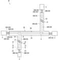
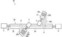
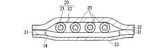
以下、実施形態に係る配線部材について説明する。図1は実施形態にかかる配線部材10を示す平面図である。図2は折り畳まれた状態の配線部材10を示す平面図である。図3は図1のIII-II線に沿った断面図である。図3は図1のIV-IV線に沿った断面図である。[Embodiment]
A wiring member according to an embodiment will be described below. FIG. 1 is a plan view showing a
配線部材10は、複数の線状伝送部材20と、シート30とを備える。複数の線状伝送部材20は、幹線部分24と分岐線部分26とを含む態様に配線されている。 The
線状伝送部材20は、電気又は光等を伝送する線状の部材であればよい。例えば、線状伝送部材20は、芯線21と芯線21の周囲の被覆22とを有する一般電線であってもよいし、裸導線、シールド線、エナメル線、ニクロム線、光ファイバ等であってもよい。 The
電気を伝送する線状伝送部材20としては、各種信号線、各種電力線であってもよい。電気を伝送する線状伝送部材20は、信号又は電力を空間に対して送る又は空間から受けるアンテナ、コイル等として用いられてもよい。 Various signal lines and various power lines may be used as the
線状伝送部材20は、電気又は光等を伝送する伝送線本体と、伝送線本体を覆う被覆とを含む。線状伝送部材20が一般電線である場合、伝送線本体は芯線21であり、被覆は絶縁被覆22である。芯線21は複数の素線によって構成されていてもよい。複数の素線は撚られていてもよい。図3に示す例では、一のシート30に同じ径、構造の線状伝送部材20が複数本配設されているが、複数本の線状伝送部材20の径、構造等は適宜設定されていればよく、径、構造等の異なる線状伝送部材20が同じシート30に配設されていてもよい。 The
線状伝送部材20は、単一の線状物であってもよいし、複数の線状物の複合物(ツイスト線、複数の線状物を集合させてこれをシースで覆ったケーブル等)であってもよい。線状伝送部材20の端部には、線状伝送部材20と相手部材との接続形態に応じて、適宜端子、コネクタC等が設けられる。 The
複数の線状伝送部材20は、幹線部分24と分岐線部分26とを含む形態に配線されている。ここでは、分岐線部分26が2つ設けられている。以下では、2つの分岐線部分26について第1分岐線部分26A、第2分岐線部分26Bと区別されることがある。 A plurality of
第1分岐線部分26Aは、幹線部分24における一側部から分岐し、第2分岐線部分26Bは、幹線部分24における他側部から分岐している。第1分岐線部分26A、第2分岐線部分26Bは、幹線部分24の長手方向に沿って相互に異なる位置から分岐している。第1分岐線部分26A、第2分岐線部分26Bの長手方向は幹線部分24の長手方向に対して直交している。もちろん、幹線部分24及び分岐線部分26の経路は上記したものに限られない。例えば、分岐線部分26は1つであってもよいし、3つ以上であってもよい。また例えば、2つの分岐線部分26が幹線部分24における一側部から分岐していてもよい。また例えば、2つの分岐線部分26が幹線部分24の長手方向に沿って同じ位置から分岐していてもよい。また例えば分岐線部分26の長手方向は幹線部分24の長手方向に対して平行も直交もしていなくてもよい。つまり、分岐線部分26の長手方向は幹線部分24の長手方向に対して0度より大きく90度より小さい角度で交差していてもよい。 The first
図1に示す例では、シート30上に7本の線状伝送部材20が配設されている。7本の線状伝送部材20はそれぞれ所定の経路に沿って配線されている。以下では、7本の線状伝送部材20について線状伝送部材20A、20B、20C、20D、20E、20F、20Gと区別されることがある。具体的には、線状伝送部材20A、20Bは、シート30上において幹線部分24のみを構成するように配線される。線状伝送部材20C、20Dは、シート30上において一部が幹線部分24を構成し、他の一部が第1分岐線部分26Aを構成するように配線される。線状伝送部材20E、20Fは、シート30上において一部が幹線部分24を構成し、他の一部が第2分岐線部分26Bを構成するように配線される。線状伝送部材20Gは、シート30上において中間部が幹線部分24を構成し、一端部が第1分岐線部分26Aを構成し、他端部が第2分岐線部分26Bを構成するように配線される。 In the example shown in FIG. 1, seven
シート30には、線状伝送部材20が固定される。シート30は線状伝送部材20の配線形態を保つ。ここではシート30は、第1シート31と第2シート32とを含む。第1シート31は線状伝送部材20の一方を覆う。第2シート32は線状伝送部材20の他方(第1シート31とは反対側)を覆う。線状伝送部材20における中間部は第1シート31及び第2シート32に包まれている。これにより、線状伝送部材20における中間部が露出することが抑制されている。 A
ここでは線状伝送部材20は第1シート31及び第2シート32のうち第1シート31のみに固定されている。線状伝送部材20と第1シート31との固定態様は特に限定されるものではなく、接着、溶着などであってもよい。接着とは、接着剤、両面粘着テープなどの介在物を介して2つの部材がくっつくことを言う。溶着とは、介在物を介さずに、2つの部材のうち少なくとも一方に含まれる樹脂が溶けて2つの部材がくっつくことを言う。ここでは線状伝送部材20の被覆22に含まれる樹脂と、第1シート31に含まれる樹脂とのうち少なくとも一方が溶けて相手側の部材にくっつくことによって、線状伝送部材20と第1シート31とが固定される。 Here, the
第1シート31及び第2シート32を構成する材料は特に限定されるものではないが、第1シート31及び第2シート32は、例えばPVC(ポリ塩化ビニル)、PET(ポリエチレンテレフタレート)、PP(ポリプロピレン)、ナイロンなどの樹脂を含む材料によって形成される。第1シート31及び第2シート32は、不織布、織地、編地など繊維を有する繊維材等であってもよいし、非繊維材であってもよい。非繊維材としては、内部が一様に埋った充実状の部材、または樹脂が発泡成形された発泡体などであってもよい。第1シート31及び第2シート32は、金属などの材料を含むこともあり得る。 The material forming the
第1シート31及び第2シート32は、単層であってもよいし、複数層積層されていてもよい。複数層積層されている場合、例えば、樹脂層と樹脂層とが積層されていることが考えられる。また例えば、樹脂層と金属層とが積層されていることが考えられる。また、第1シート31及び第2シート32は、非繊維材層と非繊維材層とが重ねられたものであってもよいし、非繊維材層と繊維材層が重ねられたものであってもよいし、繊維材層と繊維材層とが重ねられたものであってもよい。 The
第1シート31は、例えば、2層構造とされる。第1シート31における第1層は線状伝送部材20との固定に向いた層である。例えば第1層は、線状伝送部材20の被覆22と同じ樹脂を材料として、内部が一様に埋った充実状の部材に形成される。線状伝送部材20は第1層上に固定される。第2層は、シート30の機能を高める層である。例えば第2層は、不織布である。第1層は第2層に対して全体的に設けられていてもよいし、部分的に設けられていてもよい。例えば第1層は第2層における幅方向(線状伝送部材20の並列方向)に沿って中間部にのみ設けられ、側縁部に設けられていなくてもよい。また例えば第1層は第2層における長手方向(線状伝送部材20の長手方向)に沿って、間隔をあけて設けられていてもよい。 The
第2シート32は、例えば、1層構造とされる。第2シート32は第1シート31よりも剛性が高く形成されている。第2シート32は、例えば、ナイロンを材料として、内部が一様に埋った充実状の部材に形成される。線状伝送部材20は第2シート32には固定されていない。第2シート32の縁部が第1シート31と固定される。第1シート31と第2シート32との固定態様は特に限定されるものではなく、溶着、接着などであってもよい。第2シート32は、第1シート31における第1層に固定されていてもよいし、第2層に固定されていてもよい。 The
シート30は、幹線固定部34と分岐線固定部36とを含む。幹線固定部34は幹線部分24が固定された部分である。分岐線固定部36は分岐線部分26が固定された部分である。分岐線固定部36は、幹線固定部34から分岐している。つまり分岐線固定部36は幹線固定部34とつながっている。ここでは、分岐線固定部36は、幹線固定部34の長手方向中間部において分岐している。分岐線固定部36は第1分岐線固定部36Aと第2分岐線固定部36Bとを有する。第1分岐線固定部36Aは、第1分岐線部分26Aが固定された部分である。第2分岐線固定部36Bは、第2分岐線部分26Bが固定された部分である。 The
配線部材10には折曲げ容易部12が設けられている。折曲げ容易部12は、シート30が存在する領域に設けられている。折曲げ容易部12は第2シート32が線状伝送部材20の長手方向に沿って間隔をあけて設けられた部分である。つまり折曲げ容易部12は線状伝送部材20の長手方向に沿って第2シート32がない部分である。なお、上記では第2シート32が無い構成を示したが本構成に限定されず、例えば折曲げ容易部12に対応する位置の第2シート32の剛性を折曲げ容易部12以外の領域の第2シート32と比較して低くすれば良い。すなわち、折曲げ容易部は第2シート32が部分的に折り曲げ容易な形状に形成されていてもよい。折り曲げ容易な形状として例えば蛇腹形状であってもよい。蛇腹形状は、線状伝送部材20の長手方向に山、谷が交互に連続する蛇腹状に形成された部分である。端末側部分が折曲げ容易部12の位置で折り曲げられることによって配線部材10は折り畳まれた状態となる。 The
なお、上記に折曲げ容易部12として一例を挙げたが、折曲げ容易部12は例えば折り目(図示しない)など部分的に折曲げ容易な形状であれば良く、特に限定されない。例えば第2シート32ではなく、第1シート31にスリットを入れること等(図示しない)により、折曲げ容易部12とする形状であっても良い。 An example of the easily
配線部材10には真空吸着箇所が設定されている。図1に示す例では二点鎖線で示される領域Aが真空吸着箇所である。図1に示す例では、真空吸着箇所は2箇所設定されている。真空吸着箇所は、その位置で配線部材10が真空吸着されて持ち上げられた場合に、配線部材10が傾きにくく、概ね平衡を保てる箇所に設定される。一の配線部材10における真空吸着箇所の数は2箇所に限られない。例えば配線部材10が比較的小さい場合などでは、真空吸着箇所は1箇所であってもよい。また例えば配線部材10が比較的大きい場合などでは、真空吸着箇所は3箇所以上であってもよい。配線部材10が折り畳まれる場合、真空吸着箇所は折り畳まれた状態の配線部材10において露出する箇所に設けられると良い。なお、便宜上、真空吸着として記載しているが真空に限定されないことは言うまでも無い。吸着して持ち上げ可能な程度の負圧を有していれば良い。 The
配線部材10には窓領域14が設けられている。配線部材10が外方から観察されたとき、複数の線状伝送部材20のうち窓領域14に配線された部分が識別可能である。複数の線状伝送部材20のうち窓領域14に配線された部分の識別方法は特に限定されない。例えば撮像素子によって撮像された撮像画像を基に識別装置又は作業者によって識別されてもよい。また例えば作業者によって直接視認されることによって識別されてもよい。窓領域14は、シート30のうち複数の線状伝送部材20の長手方向に沿った一部に設けられている。 A
複数の線状伝送部材20の長手方向に沿った窓領域14の位置は、特に限定されるものではない。窓領域14は、例えば、線状伝送部材20が露出しても問題ない箇所に設けられていてもよい。例えば、配線部材10におけるシート30が設けられる部分において、第1保護領域と第2保護領域とが設定される。第2保護領域は、第1保護領域よりも保護する必要の高い箇所である。保護する必要の高い箇所は、例えば、配線部材10において周辺部材と干渉しやすい箇所であったり、熱の影響が大きかったりする箇所である。窓領域14は第2保護領域を避けて第1保護領域に設けられていると良い。なおここでは窓領域14における線状伝送部材20の保護のため透明シート33が設けられているが、保護する必要性が低い場合、透明シート33は省略されてもよい。 The positions of the
窓領域14は分岐線固定部36に設けられている。窓領域14は、第1窓領域14Aと第2窓領域14Bとを有する。第1窓領域14Aは第1分岐線部分26Aに対応する位置に設けられている。第1窓領域14Aは第1分岐線固定部36Aに設けられている。第2窓領域14Bは第2分岐線部分26Bに対応する位置に設けられている。第2窓領域14Bは第2分岐線固定部36Bに設けられている。 The
窓領域14は、配線部材10が折り畳まれた状態で外面を向く側に設けられている。ここでは配線部材10は、第2シート32を内側にして折り畳まれる。そして、窓領域14は、配線部材10のうち折曲げ箇所よりも端末側部分に設けられている。このため、窓領域14は、折曲げ箇所よりも端末側部分において外面を向く第1シート31側に設けられている。もちろん窓領域が第2シート32に設けられていてもよい。以下の窓領域14に係る構成は、第1シート31に設けられているものとして説明される。以下の窓領域14に係る構成は、第2シート32に設けられた場合にも矛盾のない限り、適宜適用可能である。 The
窓領域14は第1シート31において長手方向に沿った一部が部分的になくなっている部分である。ここでは窓領域14は第1シート31の幅方向中間部に設定されている。第1シート31のうち窓領域14に対応する部分には厚み方向に貫通孔が形成されている。第1シート31の幅方向に沿って窓領域14の隣には第1シート31が存在している。第1シート31のうち幅方向に沿って窓領域14の隣に位置する部分は、第2シート32と固定されている。 The
もっとも窓領域14は第1シート31の幅方向に沿った一方端部に及ぶように設けられていてもよいし、両端部に及ぶように設けられていてもよい。後者の場合、窓領域14によって第1シート31が完全に分断された状態となる。つまり第1シート31は線状伝送部材20の長手方向に沿って間隔をあけて設けられた状態となり、第1シート31の間の部分が窓領域となる。 However, the
窓領域14が第1シート31の幅方向に沿った一部に設けられる場合、窓領域14の幅寸法及び幅方向に沿った位置は、少なくとも一部の線状伝送部材20が識別できるように設定されていればよい。窓領域14の幅寸法及び幅方向に沿った位置は、当該窓領域14が形成される分岐線部分26を構成する線状伝送部材20のすべてを識別できるように設定されていてもよい。 When the
窓領域14は、例えば、一様に広がる第1シート31のうち窓領域14に対応する一部分が切除されることによって形成される。この際、第1シート31は線状伝送部材20が固定される工程の前に予め切除されていてもよいし、線状伝送部材20が固定される工程の後に切除されていてもよい。後者の場合、第1シート31のうち切除される部分には線状伝送部材20が固定されていないとよい。 The
窓領域14は、配線部材10が折り畳まれた状態で外部に露出する位置に設けられている。配線部材10が折り畳まれた状態で外部に露出する位置とは、配線部材10が折り畳まれた状態で、配線部材10のうち外向きの位置であって、その上に折り畳まれた端末側部分が重ならない位置である。ここでは窓領域14は、折曲げ箇所よりも端末側に設けられていることによって、配線部材10が折り畳まれた状態で外部に露出する位置に設けられている。 The
シート30は透明シート33をさらに含む。透明シート33は窓領域14に被さっている。ここでは窓領域14において第1シート31がない。そこで透明シート33が第1シート31の代わりに窓領域14を覆っている。透明シート33は第1シート31の外側に位置していてもよいし、内側に位置してもよい。
透明シート33は、第1シート31に固定されていてもよいし、線状伝送部材20に固定されていてもよいし、第2シート32に固定されていてもよい。透明シート33と固定相手との固定態様は、特に限定されるものではなく、接着、溶着等であってもよい。透明シート33は例えば窓領域14よりも大きく形成されて、窓領域14の外側の周縁部分が固定相手に固定されていると良い。 The
透明シート33の厚み寸法は特に限定されるものではない。透明シート33の厚み寸法は、第1シート31の厚み寸法と同じであってもよいし、それよりも厚くてもよいし、薄くてもよい。透明シート33の厚み寸法は、第2シート32の厚み寸法と同じであってもよいし、それよりも厚くてもよいし、薄くてもよい。 The thickness dimension of the
第1シート31、第2シート32の色は特に限定されるものではない。第1シート31、第2シート32のうち窓領域14を仕切る枠となる方(ここでは第1シート31)は線状伝送部材20の色と異なる色であってもよい。第1シート31、第2シート32のうち窓領域14における背景となる方(ここでは第2シート32)は線状伝送部材20の色と異なる色であってもよい。第1シート31の色と第2シート32の色とは同じであってもよいし、異なっていてもよい。第1シート31及び第2シート32は、透明シート33よりも不透明であってもよい。透明シート33の色は特に限定されるものではないが、無色であってもよい。 The colors of the
窓領域14は、折り畳まれた状態の配線部材10をロボットが車両に組付ける際、基準となる位置(以下、基準位置と呼ばれる)の近傍に位置すると良い。これにより、ロボットが窓領域14と基準位置とを併せて認識しやすくなる。 The
基準位置としては、例えば、上記真空吸着箇所のように折り畳まれた状態の配線部材10をロボットが保持する保持箇所であってもよい。折り畳まれた状態の配線部材10をロボットが保持する位置としては、真空吸着箇所のほかに例えば、把持箇所が考えられる。把持箇所は、ロボットが折り畳まれた状態の配線部材10を把持する箇所である。保持箇所には、ロボットが配線部材10を保持するのに適した構造が付与されていてもよい。さらにその構造が、配線部材10における外観上特異なものであってもよい。 The reference position may be, for example, a holding position where the robot holds the
基準位置としては、保持箇所のほか、例えば、折り畳まれた状態の配線部材10を車両に固定する車両固定箇所が挙げられる。車両固定箇所には、固定用の構造が付与されていてもよい。例えば、車両固定箇所には、折り畳まれた状態の配線部材10を車両に固定可能な態様で、固定部材が設けられていたり、車両側の固定部材が固定される受部が設けられていたりすることが考えられる。 As the reference position, in addition to the holding position, for example, a vehicle fixing position for fixing the
配線部材10が折り畳まれる場合、窓領域14は、折り畳まれる前の状態(展開状態)よりも基準位置に近づく位置にあってもよい。ここでは窓領域14は、折曲げ箇所より端末側に位置し、かつ折曲げ箇所より端末側部分が基準位置としての保持位置に近づく位置に設けられている。このため、窓領域14は、折り畳まれる前の状態よりも基準位置に近づく位置に設けられている。 When the
配線部材10は、窓領域14に配線された線状伝送部材20が識別されることによって、その種類等が識別される。識別態様は特に限定されるものではないが、例えば、窓領域14の大きさ、窓領域14における面積(線状伝送部材20の面積)、窓領域14に配線された線状伝送部材20の色(被覆22の色)、窓領域14の位置(コネクタCからの距離)などの違いでその種類が識別されることができる。すなわち複数種類の配線部材10において、窓領域14の大きさが異なったり、窓領域14における面積が異なったり、窓領域14に配線された線状伝送部材20の色が異なったり、窓領域14の位置が異なったりすることによって、その種類等が識別される。 The type of the
さらにここでは配線部材10において、窓領域14によって複数の分岐線部分26も識別される。この場合、窓領域14を識別するにあたり、窓領域14の大きさ、窓領域14における面積(線状伝送部材20の面積)、窓領域14に配線された線状伝送部材20の色(被覆22の色)、窓領域14の位置(コネクタCからの距離)などの識別態様が複数識別されると良い。つまり、配線部材10の種類等の識別に使用される識別態様と、複数の分岐線部分26の識別に使用される識別態様とが異なっていると良い。 Furthermore, in the
具体的には、一の配線部材10において、第1窓領域14A、第2窓領域14Bに第1識別態様が設定される。第1識別態様は、一の配線部材10と他の配線部材とを識別するためのものである。従って、第1識別態様の観点において、第1窓領域14A、第2窓領域14Bは共通の外観に設定される。例えば、一の配線部材10において、第1窓領域14A、第2窓領域14Bにおける線状伝送部材20の色が共通である。この色は、他の配線部材の窓領域における線状伝送部材の色とは異なる。これにより、一の配線部材10と他の配線部材とを識別できる。一の配線部材10において、第1窓領域14A、第2窓領域14Bに第2識別態様が設定される。第2識別態様は、第1分岐線部分26A及び第2分岐線部分26Bを識別するためのものである。従って、第2識別態様の観点において、第1窓領域14A、第2窓領域14Bは異なる外観に設定される。例えば、第1窓領域14A、第2窓領域14Bにおける線状伝送部材20の面積が異なっている。これにより、一の配線部材10において、第1分岐線部分26A及び第2分岐線部分26Bを識別できる。 Specifically, in one
<実施形態の効果等>
以上のように構成された配線部材10によると、複数の線状伝送部材20のうち窓領域14に配線された部分が識別されることによって、その配線部材10の種類等が識別される。配線部材10は折り畳まれた状態で組付作業箇所へ搬送されて、組付け作業箇所で展開されることが多い。この場合でも、配線部材10が折り畳まれた状態で外面を向く側に窓領域14が設けられているため、組付作業箇所において折り畳まれた状態にある所定の配線部材10を容易に特定することができる。<Effects of the embodiment, etc.>
According to the
また窓領域14が分岐線部分26に設けられているため、窓領域14によって、配線部材10の特定に加えて、分岐線部分26の特定も併せて行うことができる。 Further, since the
また複数の線状伝送部材20のうち第1窓領域14Aにおける外観と、第2窓領域14Bにおける外観とが異なっているため、第1分岐線部分26Aと第2分岐線部分26Bとを識別可能となる。 In addition, since the appearance of the
また窓領域14は、折り畳まれた状態で外部に露出する位置に設けられているため、折り畳まれた部分が重なって窓領域14が見えなくなることを抑制できる。 In addition, since the
また窓領域14に透明シート33が被せられるため、シート30が設けられつつ、窓領域14も設けられることができる。 Further, since the
[変形例]
窓領域14が分岐線部分26に設けられる必要はない。窓領域14は幹線部分24に設けられていてもよい。また複数の線状伝送部材20は幹線部分24と分岐線部分26とを含む態様に配線されていなくてもよい。[Modification]
分岐線部分26が複数ある場合に、窓領域14は複数の分岐線部分26のうち一部の分岐線部分26のみに設けられていてもよく、一の分岐線部分26のみに設けられていてもよい。窓領域14が複数の分岐線部分26に設けられる場合に、その外観が異なっている必要はない。例えば、複数の窓領域14のうちいずれか一つが識別されることによって、その配線部材10の種類を特定したい場合、複数の窓領域14が共通の外観を有していてもよい。 When there are a plurality of
なお、上記実施形態及び各変形例で説明した各構成は、相互に矛盾しない限り適宜組み合わせることができる。 In addition, each structure demonstrated by the said embodiment and each modification can be combined suitably, unless it mutually contradicts.
10 配線部材
12 折曲げ容易部
14 窓領域
14A 第1窓領域
14B 第2窓領域
20、20A、20B、20C、20D、20E、20F、20G 線状伝送部材
21 芯線
22 被覆
24 幹線部分
26 分岐線部分
26A 第1分岐線部分
26B 第2分岐線部分
30 シート
31 第1シート
32 第2シート
33 透明シート
34 幹線固定部
36 分岐線固定部
C コネクタ
A 領域REFERENCE SIGNS
Claims (5)
Translated fromJapanese前記複数の線状伝送部材が並んだ状態に固定されるシートと、
を備える配線部材であって、
前記シートは前記複数の線状伝送部材を一方側から覆う第1シートと、前記複数の線状伝送部材を他方側から覆う第2シートとを含み、
前記シートのうち前記複数の線状伝送部材の長手方向に沿った一部には窓領域が設けられており、
前記窓領域は、当該配線部材が折り畳まれた状態で外面を向く側に設けられており、
前記複数の線状伝送部材のうち前記窓領域に配線された部分が識別可能である、配線部材。a plurality of linear transmission members;
a sheet on which the plurality of linear transmission members are fixed in a row;
A wiring member comprising
The sheet includes a first sheet covering the plurality of linear transmission members from one side and a second sheet covering the plurality of linear transmission members from the other side,
A window region is provided in a part of the sheet along the longitudinal direction of the plurality of linear transmission members,
The window region is provided on the side facing the outer surface when the wiring member is folded,
A wiring member, wherein a portion of the plurality of linear transmission members wired to the window region is identifiable.
前記複数の線状伝送部材は、幹線部分と分岐線部分とを含む態様に配線されており、
前記シートは前記幹線部分が固定される幹線固定部と、前記分岐線部分が固定される分岐線固定部とを有し、
前記窓領域は前記分岐線固定部に設けられている、配線部材。The wiring member according to claim 1,
the plurality of linear transmission members are wired in a manner including a main line portion and a branch line portion;
The seat has a main line fixing portion to which the main line portion is fixed, and a branch line fixing portion to which the branch line portion is fixed,
The wiring member, wherein the window region is provided in the branch line fixing portion.
前記分岐線部分は、第1分岐線部分と第2分岐線部分とを有し、
前記窓領域は、前記第1分岐線部分に対応する位置に設けられた第1窓領域と、前記第2分岐線部分に対応する位置に設けられた第2窓領域とを有し、
前記複数の線状伝送部材のうち前記第1窓領域における外観と、前記第2窓領域における外観とが異なっている、配線部材。The wiring member according to claim 2,
The branch line portion has a first branch line portion and a second branch line portion,
The window region has a first window region provided at a position corresponding to the first branch line portion and a second window region provided at a position corresponding to the second branch line portion,
A wiring member, wherein the appearance of the first window region and the appearance of the second window region of the plurality of linear transmission members are different.
前記窓領域は、当該配線部材が折り畳まれた状態で外部に露出する位置に設けられている、配線部材。The wiring member according to any one of claims 1 to 3,
The wiring member, wherein the window region is provided at a position exposed to the outside when the wiring member is folded.
前記シートは前記窓領域に被せられた透明シートをさらに含む、配線部材。The wiring member according to any one of claims 1 to 4,
The wiring member, wherein the sheet further includes a transparent sheet covering the window region.
Priority Applications (5)
| Application Number | Priority Date | Filing Date | Title |
|---|---|---|---|
| JP2019102898AJP7226111B2 (en) | 2019-05-31 | 2019-05-31 | Wiring material |
| DE112020002611.6TDE112020002611T5 (en) | 2019-05-31 | 2020-05-14 | wiring component |
| PCT/JP2020/019193WO2020241267A1 (en) | 2019-05-31 | 2020-05-14 | Wiring member |
| CN202080038410.9ACN113874964B (en) | 2019-05-31 | 2020-05-14 | Wiring member |
| US17/611,749US20220234526A1 (en) | 2019-05-31 | 2020-05-14 | Wiring member |
Applications Claiming Priority (1)
| Application Number | Priority Date | Filing Date | Title |
|---|---|---|---|
| JP2019102898AJP7226111B2 (en) | 2019-05-31 | 2019-05-31 | Wiring material |
Publications (2)
| Publication Number | Publication Date |
|---|---|
| JP2020198188A JP2020198188A (en) | 2020-12-10 |
| JP7226111B2true JP7226111B2 (en) | 2023-02-21 |
Family
ID=73554062
Family Applications (1)
| Application Number | Title | Priority Date | Filing Date |
|---|---|---|---|
| JP2019102898AActiveJP7226111B2 (en) | 2019-05-31 | 2019-05-31 | Wiring material |
Country Status (5)
| Country | Link |
|---|---|
| US (1) | US20220234526A1 (en) |
| JP (1) | JP7226111B2 (en) |
| CN (1) | CN113874964B (en) |
| DE (1) | DE112020002611T5 (en) |
| WO (1) | WO2020241267A1 (en) |
Families Citing this family (3)
| Publication number | Priority date | Publication date | Assignee | Title |
|---|---|---|---|---|
| JP7358935B2 (en)* | 2019-11-21 | 2023-10-11 | 株式会社オートネットワーク技術研究所 | wiring parts |
| JP7643211B2 (en)* | 2021-06-30 | 2025-03-11 | 株式会社オートネットワーク技術研究所 | Wiring materials |
| JP2024084212A (en)* | 2022-12-13 | 2024-06-25 | 株式会社オートネットワーク技術研究所 | Wire harness arrangement structure and wire harness |
Citations (1)
| Publication number | Priority date | Publication date | Assignee | Title |
|---|---|---|---|---|
| JP3161391U (en) | 2010-05-18 | 2010-07-29 | エス・ディ・ケイ株式会社 | code |
Family Cites Families (26)
| Publication number | Priority date | Publication date | Assignee | Title |
|---|---|---|---|---|
| US3547718A (en)* | 1967-05-18 | 1970-12-15 | Rogers Corp | Method of making flat flexible electrical cables |
| US3697925A (en)* | 1970-07-22 | 1972-10-10 | Amp Inc | Termination means for flat cable |
| US4815990A (en)* | 1987-04-10 | 1989-03-28 | Rogers Corporation | Flexible circuit having termination features and method of making the same |
| US5281765A (en)* | 1992-05-27 | 1994-01-25 | Sumitomo Wiring Systems, Ltd. | Wiring assembly for equipment and a method for producing the same |
| US5973265A (en)* | 1997-08-29 | 1999-10-26 | Lear Automotive Dearborn, Inc. | Wire harness with splice locators |
| JP3799783B2 (en)* | 1997-11-13 | 2006-07-19 | 住友電装株式会社 | Flexible wiring assembly |
| JP2000252016A (en)* | 1998-12-28 | 2000-09-14 | Teac Corp | Code terminal indicator and display method |
| JP2001110484A (en)* | 1999-10-12 | 2001-04-20 | Yazaki Corp | Flat circuit body connection device and connection method |
| JP3649102B2 (en)* | 2000-08-11 | 2005-05-18 | 住友電装株式会社 | Bent flat harness |
| US7134200B2 (en)* | 2000-11-01 | 2006-11-14 | International Business Machines Corporation | Device and method for identifying cables |
| US20020081894A1 (en)* | 2000-12-21 | 2002-06-27 | Fuerst Robert M. | Flat flexible circuit interconnections |
| JP2003151378A (en)* | 2001-11-14 | 2003-05-23 | Sumitomo Wiring Syst Ltd | Distribution cable and its distinguishing method |
| EP1443619B1 (en)* | 2003-01-29 | 2006-06-14 | I & T Innovation Technology Entwicklungs- und Holding Aktiengesellschaft | Stripping of flat conductors |
| JP5270918B2 (en)* | 2004-10-29 | 2013-08-21 | コーニンクレッカ フィリップス エレクトロニクス エヌ ヴィ | Device with frontmost surface and display |
| JP2007335296A (en)* | 2006-06-16 | 2007-12-27 | Sony Chemical & Information Device Corp | Flexible flat cable with carrier tape and its manufacturing method |
| JP5128228B2 (en)* | 2007-10-02 | 2013-01-23 | 古河電気工業株式会社 | Flat cable connection end structure |
| JP4506818B2 (en)* | 2007-11-15 | 2010-07-21 | 住友電気工業株式会社 | Manufacturing method of shielded flat cable |
| CN201465637U (en)* | 2009-06-26 | 2010-05-12 | 河南省电力公司焦作供电公司 | A cable with auxiliary metering function |
| CN202339727U (en)* | 2011-10-19 | 2012-07-18 | 汤广顺 | Heat resistant shielded cable with visible window |
| CN105103243B (en)* | 2013-02-05 | 2017-11-28 | 古河电气工业株式会社 | Electric wire structure, electrical connection structure, and method for manufacturing electric wire structure |
| CN105351797B (en)* | 2015-10-14 | 2018-07-27 | 崇义县精亿灯饰制品有限公司 | A kind of tendril lamp and preparation method thereof |
| MX2018009846A (en)* | 2016-02-19 | 2018-11-09 | Gen Cable Technologies Corp | Laser-markable cables and systems for making the same. |
| CN205680486U (en)* | 2016-04-26 | 2016-11-09 | 成都大西洋线缆有限公司 | A kind of waterproof low-voltage cable |
| JP6497420B2 (en) | 2017-02-23 | 2019-04-10 | 株式会社オートネットワーク技術研究所 | Wire Harness |
| CN207938865U (en)* | 2017-10-18 | 2018-10-02 | 杭州警智科技有限公司 | A kind of waistband winding displacement with flexible glue sheath |
| US11037706B2 (en)* | 2018-05-15 | 2021-06-15 | Aptiv Technologies Limited | Apparatus and method for manufacturing assembly having multiple separated conductors embedded within a substrate |
- 2019
- 2019-05-31JPJP2019102898Apatent/JP7226111B2/enactiveActive
- 2020
- 2020-05-14DEDE112020002611.6Tpatent/DE112020002611T5/enactivePending
- 2020-05-14CNCN202080038410.9Apatent/CN113874964B/enactiveActive
- 2020-05-14USUS17/611,749patent/US20220234526A1/ennot_activeAbandoned
- 2020-05-14WOPCT/JP2020/019193patent/WO2020241267A1/ennot_activeCeased
Patent Citations (1)
| Publication number | Priority date | Publication date | Assignee | Title |
|---|---|---|---|---|
| JP3161391U (en) | 2010-05-18 | 2010-07-29 | エス・ディ・ケイ株式会社 | code |
Also Published As
| Publication number | Publication date |
|---|---|
| WO2020241267A1 (en) | 2020-12-03 |
| DE112020002611T5 (en) | 2022-02-17 |
| US20220234526A1 (en) | 2022-07-28 |
| CN113874964A (en) | 2021-12-31 |
| JP2020198188A (en) | 2020-12-10 |
| CN113874964B (en) | 2024-10-01 |
Similar Documents
| Publication | Publication Date | Title |
|---|---|---|
| JP7226111B2 (en) | Wiring material | |
| US11007954B2 (en) | Sheeted harness | |
| JP7279520B2 (en) | Wiring material | |
| JP7334610B2 (en) | Wiring material | |
| WO2021049620A1 (en) | Wiring member | |
| WO2020121463A1 (en) | Wire harness and method for producing wire harness | |
| WO2021200158A1 (en) | Wiring member | |
| JP2020044874A (en) | Wire harness, assembly structure of wire harness to roof liner, packaging structure of wire harness | |
| WO2021205883A1 (en) | Wiring member | |
| JP2023041695A (en) | Wiring member | |
| JP7314793B2 (en) | Wiring material | |
| JP2007288898A (en) | Wire harness branch protection structure | |
| WO2021095525A1 (en) | Wiring member | |
| WO2023276687A1 (en) | Wiring member | |
| US12081001B2 (en) | Wiring member having a buffer member | |
| WO2020148883A1 (en) | Wiring member | |
| JP7140052B2 (en) | Wiring material | |
| WO2021095522A1 (en) | Wiring member | |
| JP5083163B2 (en) | Wire harness | |
| JP7754270B2 (en) | Wiring materials | |
| JP5607133B2 (en) | Fixed structure for linear objects | |
| JP2022081166A (en) | Instrument panel harness | |
| JP2007049784A (en) | Wiring harness wiring structure for automobile |
Legal Events
| Date | Code | Title | Description |
|---|---|---|---|
| A621 | Written request for application examination | Free format text:JAPANESE INTERMEDIATE CODE: A621 Effective date:20210830 | |
| A131 | Notification of reasons for refusal | Free format text:JAPANESE INTERMEDIATE CODE: A131 Effective date:20220913 | |
| A601 | Written request for extension of time | Free format text:JAPANESE INTERMEDIATE CODE: A601 Effective date:20221108 | |
| A521 | Request for written amendment filed | Free format text:JAPANESE INTERMEDIATE CODE: A523 Effective date:20221209 | |
| TRDD | Decision of grant or rejection written | ||
| A01 | Written decision to grant a patent or to grant a registration (utility model) | Free format text:JAPANESE INTERMEDIATE CODE: A01 Effective date:20230110 | |
| A61 | First payment of annual fees (during grant procedure) | Free format text:JAPANESE INTERMEDIATE CODE: A61 Effective date:20230123 | |
| R150 | Certificate of patent or registration of utility model | Ref document number:7226111 Country of ref document:JP Free format text:JAPANESE INTERMEDIATE CODE: R150 |