JP7225651B2 - cap with nozzle - Google Patents
cap with nozzleDownload PDFInfo
- Publication number
- JP7225651B2 JP7225651B2JP2018188310AJP2018188310AJP7225651B2JP 7225651 B2JP7225651 B2JP 7225651B2JP 2018188310 AJP2018188310 AJP 2018188310AJP 2018188310 AJP2018188310 AJP 2018188310AJP 7225651 B2JP7225651 B2JP 7225651B2
- Authority
- JP
- Japan
- Prior art keywords
- nozzle
- cap
- opening
- container
- plate portion
- Prior art date
- Legal status (The legal status is an assumption and is not a legal conclusion. Google has not performed a legal analysis and makes no representation as to the accuracy of the status listed.)
- Active
Links
Images


Landscapes
- Closures For Containers (AREA)
Description
Translated fromJapanese本発明は、液体注出容器用のノズル付きキャップに関し、詰替え袋から容器への詰替えがし易く、計量キャップへの注ぎ性が良好なノズル付きキャップに関する。 TECHNICAL FIELD The present invention relates to a cap with a nozzle for a liquid pouring container, and more particularly to a cap with a nozzle that facilitates refilling from a refill bag into a container and that is easy to pour into a measuring cap.
従来から、液体洗剤や柔軟仕上げ剤などを洗濯機に投入する際に、液体洗剤や柔軟仕上げ剤などの容器のキャップに液剤を注出して計量し、所定の量の洗剤等を投入することが行われている。そしてそのために容器のキャップには、開口部に注出し易くする注出ノズルを設けたもの、さらにオーバーキャップに計量機能を持たせたものが開発され、利用されている。 Conventionally, when putting liquid detergent, fabric softener, etc. into a washing machine, it has been possible to pour out the liquid agent into the cap of the container of the liquid detergent, fabric softener, etc., measure it, and put in a predetermined amount of detergent, etc. It is done. For this purpose, container caps provided with a pouring nozzle at the opening for easy pouring, and overcaps with a measuring function have been developed and used.
これらのキャップを装着した容器は、洗剤等の内容物を使用後に、パウチ状などの詰替え容器から内容物を詰替えて、プラスチック樹脂を成形したボトル状の容器を繰り返し使用できるようにしたものが多い。そして詰替えの際は、キャップのノズルが設けられた開口部の部分から内容物が注入される。従ってこの様な容器に装着されるキャップには、内容物を注出するだけでなく、注入も良好に行えるような性能が求められる。 Containers with these caps can be refilled from a refill container such as a pouch after using the contents such as detergent, and the bottle-shaped container made of plastic resin can be used repeatedly. There are many. When refilling, the contents are injected through the opening of the cap where the nozzle is provided. Therefore, a cap to be attached to such a container is required to have a performance that not only pours out the contents but also pours the contents well.
この様なキャップとして、例えば特許文献1には、仕切り板から上向きに突出した注出筒と、注出筒を囲んで仕切り板で結合された外壁部とからなり、注出筒に切り離し部が形成されて、切り離し部が切り離し幅の広い上方部と、切り離し幅の狭い下方部とからなる注出具を具備する液体注出容器が開示され、詰め替えが容易であり、内容物を注ぎやすく、内容物を注ぐ際にタレた液を、外壁を超えてこぼすことなく回収できるとしている。 As such a cap, for example,
しかしながら特許文献1に開示されている注出具は、液体を注出および注入する開口が、細い溝状の部分と長円形の部分が連続した形状であり、かつ溝状の部分が仕切り板の下り傾斜の低い部分となっているため、液体を注出する際は大きな開口となっている長円形の部分から流出するため、容器の傾きによる注出量の変化が大きくなり、注出量の細かい調整が困難であり、また詰替えのために注入する際は、開口が仕切り板の下り傾斜の低い部分で細い溝状となっているため、注入した液体は低い部分に溜まり易いことから、細い溝状の開口から容器内へ流れ落ちるまで注入を中断しなければならず時間がかかることがある、連続した開口から大きな空気の泡が突沸して外壁部から液体が溢れてしまうことがある、という問題があった。 However, in the pouring tool disclosed in
また、特許文献2には、上部に計量キャップを装着した注出キャップであって、注出口部と内筒壁を有し、注出口部は傾斜筒壁と傾斜底壁を有し、傾斜底壁中央部に注出口、注出筒が設けられ、傾斜底壁の最下部側に傾斜壁が設けられるなどした注出キャップが開示され、容器に装着して内容液を計量キャップに注ぐ際、容器本体を急激に傾けたとしても、傾斜壁によって流路が遮蔽されるので、注出筒のスリットより内容液が溢れたり、内容液が勢いよく飛び出し、容器外に飛び散ることを防止することができるとしている。 Further, Patent Document 2 discloses a pouring cap with a weighing cap mounted on the top, which has a pouring port and an inner cylinder wall, the pouring port has an inclined cylinder wall and an inclined bottom wall, and has an inclined bottom Disclosed is a pouring cap provided with a pouring port and a pouring cylinder at the center of the wall, and an inclined wall at the bottom of the inclined bottom wall. Even if the container body is suddenly tilted, the slanted wall blocks the flow path, preventing the content liquid from overflowing from the slit of the pouring tube, and preventing the content liquid from splashing out of the container. They say they can.
しかしながら特許文献2に開示されている注出キャップは、注出の際は所期の効果が期待できるが、詰替え時の注入の際は、注出口が単一でしかも傾斜壁により一部が遮蔽される構造であり、かつ液体と入れ替えに放出されるべき内部の空気の流路との区別がないため、注入した液体が注出口付近に滞留し易く、また空気が抜け難く、やはり液体が容器内へ流れ落ちるまで注入を中断しなければならず時間がかかることがある、または外壁部から液体が溢れてしまうことがある、という問題点は同様であった。 However, the pouring cap disclosed in Patent Document 2 can be expected to have the desired effect at the time of pouring, but at the time of pouring at the time of refilling, the pouring cap has a single pouring port and is partly covered by the inclined wall. Since it is a shielded structure and there is no distinction between the flow path of the internal air that should be discharged in exchange for the liquid, the injected liquid tends to stay near the outlet, and the air is difficult to escape. The same problem was encountered in that the injection had to be interrupted until it flowed down into the container, which sometimes took a long time, or that the liquid sometimes overflowed from the outer wall.
すなわち、この様な容器のキャップにおいては、注出量を調整し易くするためにはキャップの開口を小さくしたほうが良いのに対して、詰替えの際に注入し易くするためには開口を大きくしたほうが良く、相反する特性が求められていたのに対して、従来技術では有効な特性を持ったものがなかった。 That is, in the cap of such a container, it is better to make the opening of the cap smaller in order to facilitate adjustment of the pouring amount, whereas the opening of the cap should be made larger in order to facilitate pouring at the time of refilling. While contradictory characteristics have been sought, none of the prior art has effective characteristics.
そこで本発明では、容器に取付けて液体状の内容物を注出する時には、比較的少量の計量が容易に行えるように内容物を少しずつ注出することが容易に行え、また詰替えのために内容物を注入する際は、注入する液体と放出される容器内部の空気との交替がスムーズに行えて流入量を多くでき、効率的かつ容易に詰替えが行えるノズル付きキャップを提供することを課題とする。 Therefore, in the present invention, when the liquid content is poured out by attaching it to the container, the content can be easily poured out little by little so that relatively small amounts can be easily measured, and the container can be used for refilling. To provide a cap with a nozzle capable of smoothly exchanging the liquid to be injected and the air inside the container to be discharged when injecting contents into a container, increasing the amount of inflow, and efficiently and easily refilling the container. is the subject.
上記課題を解決するため、本発明の請求項1に係る発明は、
容器の口頚部に装着され、内容物を注出するノズルを有するノズル部と、前記ノズル部の上部に着脱自在に装着される計量キャップからなるノズル付きキャップであって、
前記ノズル部が、ノズル基部から垂直方向に立ちあがって側面に開放部を有する樋状のノズルと、前記ノズル基部の外側に前記開放部が最低部となる様に、開放部から上向して斜面状に連続する底板部と、前記底板部の周縁から垂直方向に立設された周壁部を有し、
前記ノズル基部の内側に注出口が開口し、
前記ノズルの内側の前記ノズル基部から離間した位置に、前記開放部に向けて下向して傾斜した棚板部が設けられ、
前記棚板部には、前記注出口よりも小さい小開口が、前記開放部と反対側に設けられていることを特徴とするノズル付きキャップである。In order to solve the above problems, the invention according to
A cap with a nozzle, which is attached to the mouth and neck of a container and consists of a nozzle part having a nozzle for pouring out contents, and a measuring cap detachably attached to the upper part of the nozzle part,
The nozzle part has a gutter-shaped nozzle that rises vertically from the nozzle base and has an opening on the side, and a slope that extends upward from the opening so that the opening is the lowest part outside the nozzle base.a bottom plate portion continuous in a shape , and a peripheral wall portion erected in a vertical direction from the peripheral edge of the bottom plate portion,
A spout is opened inside the nozzle base,
A shelf plate portion inclined downward toward the opening portion is provided at a position spaced apart from the nozzle base inside the nozzle,
The cap with a nozzle is characterized in that the shelf plate portion has a small opening smaller than the spout provided on the side opposite to the open portion.
また、本発明の請求項2に係る発明は、
前記周壁部に、容器の口頸部の縁を挟みこんで螺合するネジ部が設けられていることを特徴とする請求項1に記載のノズル付きキャップである。Further, the invention according to claim 2 of the present invention is
2. The cap with a nozzle according to
また、本発明の請求項3に係る発明は、
前記計量キャップが透明または半透明な材料からなり、計量目盛りが設けられていることを特徴とする請求項1または2に記載のノズル付きキャップである。Further, the invention according to claim 3 of the present invention is
3. The cap with a nozzle according to
本発明の請求項1に記載の発明によれば、容器に本発明のノズル付きキャップから詰替え用洗剤等の液剤を注入する際、ノズルの外側に注入された液剤は斜面状の底板部に沿って最低部であるノズルの開放部に導かれて注出口に流入し、ノズルの内側に注入された液剤は底板部と同様に傾斜して設けられた棚板部を流下してノズルの開放部から底板部に達し、同様に注出口に流入する。一方、液剤と交替する容器内の空気は、棚板部のノズルの開放部と反対側に設けられて最も高い側となっている小開口から容器外部に放出される。すなわち、注入される液剤と放出される空気が、互いにノズルの反対の部位に自然に導かれて別々の開口部を通るため、注入される液剤と放出される空気の交替がスムーズに行われ、滞留した液剤の流下を待つために作業を中断することなく詰め替えを行うことができる。 According to the invention of
このとき、注入する液剤の量が増え、液剤が小開口からも流入する様になった場合でも、内部の空気は小開口の一部のみからでも十分な放出が行われるため、注入される液剤と放出される空気の交替はスムーズに行われる。また、さらに注入する液剤の量が増え、液剤が小開口全体を覆う様になった場合でも、液剤は傾斜した底板部および傾斜して設けられた棚板部に沿ってノズルの開放部側に流れ易く、また空気は浮力によりノズルの開放部と反対側に設けられて最も高い側となっている小開口に集まって泡となって放出され、すなわち液剤と空気が互いに反対側に流れるように自然に整流する効果を生じるため、液剤と空気の交替がスムーズに行われる。 At this time, even if the amount of liquid to be injected increases and the liquid flows in through the small openings, the internal air is sufficiently released even from only a part of the small openings. and the replacement of the released air is carried out smoothly. In addition, even when the amount of the liquid to be injected increases and the liquid reaches the entire small opening, the liquid flows toward the open side of the nozzle along the inclined bottom plate portion and the inclined shelf plate portion. It is easy to flow, and the air gathers in the small opening provided on the opposite side of the nozzle opening and is the highest side due to buoyancy and is discharged as bubbles, that is, the liquid agent and the air flow in the opposite sides to each other. Because of the natural rectification effect, the liquid and air are smoothly exchanged.
また計量キャップによりノズル部を封止することができると共に、液剤を注出する際に所定量の計量を行って注出できる。 Further, the nozzle portion can be sealed with the measuring cap, and the liquid agent can be poured by measuring a predetermined amount.
また請求項2に記載の発明によれば、種々の容器の口頸部のネジ部の形状に合わせたネジ部を設け、口頸部の縁を挟みこんで螺合することで、種々の容器を密封する様に取付けることができ、液状の内容物を漏れることなく密封することができるノズル付きキャップが得られる。 According to the second aspect of the present invention, a threaded portion matching the shape of the threaded portion of the mouth and neck portion of various containers is provided, and the edge of the mouth and neck portion is sandwiched and screwed together, thereby making it possible to use various containers. A cap with a nozzle can be attached to hermetically seal the liquid contents without leaking.
また請求項3に記載の発明によれば、所定量の液剤を計量目盛りにより目視して正確に計り取ることができる。 Further, according to the third aspect of the present invention, a predetermined amount of the liquid agent can be measured accurately by visually observing the measuring scale.
以下、本発明の実施の形態を、図面を参照しながら詳細に説明する。なお本発明は以下に説明する実施形態に限定されるものではない。 BEST MODE FOR CARRYING OUT THE INVENTION Hereinafter, embodiments of the present invention will be described in detail with reference to the drawings. The present invention is not limited to the embodiments described below.
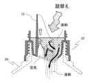
図1は、本発明のノズル付きキャップの一形態の概略構成説明図である。なお見易さのためネジ部などは省略して示している。また図2はその縦断面図であり、開放部13の中央でキャップの直径方向に切断した断面を示している。本発明のノズル付きキャップ1は、ノズル部10と、その上に装着される計量キャップ20とからなる。ノズル部10は、ノズル基部12から垂直方向に立ちあがって側面に開放部13を有する樋状のノズル11と、ノズル基部12の外側に連続する、開放部13が最低部となる様に開放部13の部分から両側に斜めに上向する斜面状となった底板部14と、底板部14のノズル11から離間した周縁から垂直方向に立設された周壁部19を有している。ノズル11は、ノズルとして有効に機能するためにその高さは周壁部19よりも高くなっている。 FIG. 1 is a schematic configuration explanatory diagram of one embodiment of the cap with a nozzle of the present invention. For ease of viewing, screw portions and the like are omitted from illustration. FIG. 2 is a vertical cross-sectional view thereof, showing a cross-section cut in the diametrical direction of the cap at the center of the
また、ノズル基部12の内側には注出口15が開口し、容器の口頸部に装着されたときに容器内部とノズル11が連通する。また、図2に示す様にノズル11の内側のノズル基部12から離間した位置に、底板部14と同方向に同等以上に傾斜した棚板部16が設けられ、棚板部16には、注出口15よりも小さい小開口17が、開放部13と反対側に設けられている。棚板部16の開放部13側の端部と、底板部14およびノズル11の側壁により略矩形の開口18が形成され、注出口15に連通している。 A
小開口17は棚板部16の開放部13と反対側の一部に設けられ、従ってその大きさは
注出口15よりも小さくなっている。小開口17の形状は、図示した例に限定されず、液剤の粘度や流動性に合わせて適宜設計して良い。The
周壁部19には、下部に容器30の口頸部の縁を挟みこんで螺合するネジ部191が設けられ、容器30の口頸部を密封して係止されるようになっている。また上部には計量キャップ20を係止するためのネジ部192が設けられている。 The
ノズル部10の上方から計量キャップ20が着脱自在に装着されている。計量キャップ20は、液剤を計量するために液剤を収納可能とするカップ部21と、計量キャップ20をノズル部10に係止するための係止部22からなり、係止部22にはここではノズル部10の周壁部19の上部に設けられたネジ部192と螺合するネジ部22で形成されている。係止部22は、これ以外にも、周壁部19と係止部22を周回する環状突起と環状凹部を嵌合させる組合せなどでも良く、ノズル部10と計量キャップ20を液剤が漏出しない様に良好に密封して係止できるものであれば特に限定されない。 A measuring
カップ部21は、液剤を計量するための所定の容積を有し、ノズル11を収納できる高さであり、基部23は底面板14に近接すると共に周壁部19の内面に隙間なく近接し、液剤が漏れ難くなっている。 The
図3は、本発明のノズル付きキャップから液剤を注出する態様の模式図である。図示しない容器から液剤40を注出し、計量キャップ20で計量する態様を示している。ノズル部10を、ノズル11の開放部13が上向きとなる様にしてノズル11中を液剤40が流下する様な向きに倒し、液剤40を計量キャップ20のカップ部21に注出する。 FIG. 3 is a schematic diagram of a mode of pouring out a liquid agent from the nozzle-equipped cap of the present invention. A
このとき、注出口15を通過した液剤40は、注出口15よりも小さな開口である小開口17により規制されて、一時に大量に流出してしまうことがないため、比較的少量の計量を行いたい場合でも注出が容易である。また、計量キャップ20を透明、または半透明な材料で構成し、さらに計量目盛り24を設けるなどすると、カップ部21に収納された液剤40の量を計量キャップ20の外部から目視で確認でき、またその量を計量目盛り24により正確に知ることができ、より好ましい。 At this time, the
次に、本発明のノズル付きキャップ1に液剤を注入する際の態様を説明する。図4は、本発明のノズル付きキャップの底板部14の平面図である。ノズル基部の内側は注出口15となっているが、ノズル基部から離間した位置に棚板部16が設けられているため、棚板部16に設けられた小開口17の部分のみが開口として見えている。また棚板部16の開放部13側の端部と底板部14の間に略矩形の開口18が図の右方に向かって開口しているが、図では見えていない。 Next, a mode of injecting a liquid agent into the
ここに液剤を注入すると、底板部14は開放部13が最低部となる様に図の左右に向かって上向する斜面をなしているため、注入された液剤は黒矢印で示すように開放部13側に向かって斜面に沿って自然に流下してゆく。そして開口18を通って注出口に流入し、容器に注入される。ノズル11の内側に注入された液剤は、底板部14と同様に傾いている棚板部16の斜面に沿って同様に開放部13側に流下し、同様に開口18を通って注出口に流入するが、小開口17から直接、注出口へと流入するものもある。 When the liquid agent is injected here, since the
図5は、内容物を注入する様子を縦断面方向から説明する図である。注入された液剤は、ノズル11の外側に注入されたものは底板部14の斜面に沿って矢印Aに示す様に開放部13側に流下し、開口18から注出口15に流入する。またノズル11の内側に注入された液剤は、矢印Bに示す様に棚板部16の斜面に沿って開放部13側に流下し、開口18を通って注出口15に流入する。また一部は矢印Cに示す様に小開口17から直接、注出口へと流入するものもある。一方、容器内部の空気は、最も高い部位である開放部13と反対側に集まり易く、白矢印に示す様に小開口17から放出される。 FIG. 5 is a view for explaining how the contents are injected from the vertical cross-sectional direction. The liquid agent injected outside the
注入される液剤の量が多く、注入された液面が小開口17よりも上になった場合でも、同様の効果が得られる。すなわち、図6に示す様に、液剤が棚板部16よりも上のレベルに達するまで注入された場合、ノズル11の外側の液剤は矢印Aに示す様に開口18に向かって流下し、開口18から注出口15に流入する。またノズル11の内側の液剤は、矢印Bに示す様に棚板部16の斜面に沿って開放部13側に流下し、開口18を通って注出口15に流入するか、矢印Cに示す様に小開口17から直接、注出口へと流入する。一方、容器内部の空気は、最も高い部位である開放部13と反対側に集まり、小開口17から泡となって放出される。 Similar effects can be obtained even when the amount of injected liquid agent is large and the injected liquid surface is above the
このように、注入される液剤と容器内部の空気が、ノズル11の開放部13とその反対側に、互いに反対側に流れる様に自然に整流されるため、注入される液剤と容器内部の空気の交替がスムーズに行われ、注入した液剤が滞留する虞が少なく、効率的に注入を行うことができる。 In this way, the liquid agent to be injected and the air inside the container are naturally rectified so that they flow to the
1・・・ノズル付きキャップ
10・・・ノズル部
11・・・ノズル
12・・・ノズル基部
13・・・開放部
14・・・底板部
15・・・注出口
16・・・棚板部
17・・・小開口
18・・・開口
19・・・周壁部
191、192・・・ネジ部
20・・・計量キャップ
21・・・カップ部
22・・・係止部
23・・・基部
24・・・計量目盛り
30・・・容器
40・・・液剤DESCRIPTION OF
Claims (1)
Translated fromJapanese前記ノズル部が、ノズル基部から垂直方向に立ちあがって側面に開放部を有する樋状のノズルと、前記ノズル基部の外側に前記開放部が最低部となる様に、開放部から上向して斜面状に連続する底板部と、前記底板部の周縁から垂直方向に立設された周壁部を有し、
前記ノズル基部の内側に注出口が開口し、
前記ノズルの内側の前記ノズル基部から離間した位置に、前記開放部に向けて下向して傾斜した棚板部が設けられ、
前記棚板部には、前記注出口よりも小さい小開口が、前記開放部と反対側に設けられていることを特徴とするノズル付きキャップ。
A cap with a nozzle, which is attached to the mouth and neck of a container and consists of a nozzle part having a nozzle for pouring out contents, and a measuring cap detachably attached to the upper part of the nozzle part,
The nozzle part has a gutter-shaped nozzle that rises vertically from the nozzle base and has an opening on the side, and a slope that extends upward from the opening so that the opening is the lowest part outside the nozzle base.a bottom plate portion continuous in a shape , and a peripheral wall portion erected in a vertical direction from the peripheral edge of the bottom plate portion,
A spout is opened inside the nozzle base,
A shelf plate portion inclined downward toward the opening portion is provided at a position spaced apart from the nozzle base inside the nozzle,
A cap with a nozzle, wherein the shelf plate portion has a small opening smaller than the spout provided on the side opposite to the open portion.
Priority Applications (1)
| Application Number | Priority Date | Filing Date | Title |
|---|---|---|---|
| JP2018188310AJP7225651B2 (en) | 2018-10-03 | 2018-10-03 | cap with nozzle |
Applications Claiming Priority (1)
| Application Number | Priority Date | Filing Date | Title |
|---|---|---|---|
| JP2018188310AJP7225651B2 (en) | 2018-10-03 | 2018-10-03 | cap with nozzle |
Publications (2)
| Publication Number | Publication Date |
|---|---|
| JP2020055609A JP2020055609A (en) | 2020-04-09 |
| JP7225651B2true JP7225651B2 (en) | 2023-02-21 |
Family
ID=70106316
Family Applications (1)
| Application Number | Title | Priority Date | Filing Date |
|---|---|---|---|
| JP2018188310AActiveJP7225651B2 (en) | 2018-10-03 | 2018-10-03 | cap with nozzle |
Country Status (1)
| Country | Link |
|---|---|
| JP (1) | JP7225651B2 (en) |
Cited By (2)
| Publication number | Priority date | Publication date | Assignee | Title |
|---|---|---|---|---|
| US12227340B2 (en) | 2015-08-14 | 2025-02-18 | Yeti Coolers, Llc | Container with magnetic cap |
| US12269666B2 (en) | 2016-10-17 | 2025-04-08 | Yeti Coolers, Llc | Container and method of forming a container |
Citations (3)
| Publication number | Priority date | Publication date | Assignee | Title |
|---|---|---|---|---|
| JP2005022693A (en) | 2003-07-01 | 2005-01-27 | Kao Corp | Weighing cap |
| JP2012056591A (en) | 2010-09-07 | 2012-03-22 | Lion Corp | Liquid dispensing container |
| JP2012224362A (en) | 2011-04-19 | 2012-11-15 | Toppan Printing Co Ltd | Reusable container |
Family Cites Families (2)
| Publication number | Priority date | Publication date | Assignee | Title |
|---|---|---|---|---|
| JP2731821B2 (en)* | 1988-10-13 | 1998-03-25 | 日本クラウンコルク株式会社 | Synthetic resin container lid with drainage control function |
| JPH08133325A (en)* | 1994-11-04 | 1996-05-28 | Kao Corp | Liquid dispensing container |
- 2018
- 2018-10-03JPJP2018188310Apatent/JP7225651B2/enactiveActive
Patent Citations (3)
| Publication number | Priority date | Publication date | Assignee | Title |
|---|---|---|---|---|
| JP2005022693A (en) | 2003-07-01 | 2005-01-27 | Kao Corp | Weighing cap |
| JP2012056591A (en) | 2010-09-07 | 2012-03-22 | Lion Corp | Liquid dispensing container |
| JP2012224362A (en) | 2011-04-19 | 2012-11-15 | Toppan Printing Co Ltd | Reusable container |
Cited By (2)
| Publication number | Priority date | Publication date | Assignee | Title |
|---|---|---|---|---|
| US12227340B2 (en) | 2015-08-14 | 2025-02-18 | Yeti Coolers, Llc | Container with magnetic cap |
| US12269666B2 (en) | 2016-10-17 | 2025-04-08 | Yeti Coolers, Llc | Container and method of forming a container |
Also Published As
| Publication number | Publication date |
|---|---|
| JP2020055609A (en) | 2020-04-09 |
Similar Documents
| Publication | Publication Date | Title |
|---|---|---|
| US20130008919A1 (en) | Apparatus and methods for dispensing fluid | |
| US3434635A (en) | Container having a spout and a hollow handle | |
| US8870027B2 (en) | Multi-bottle containers for dispensing measured quantities of liquids | |
| US5261569A (en) | Squeezable container for liquid material having a detachable measuring cap | |
| JP7225651B2 (en) | cap with nozzle | |
| JP5052883B2 (en) | Contents liquid dispensing container | |
| JP5683235B2 (en) | Dispensing container | |
| US5405055A (en) | Self-measuring liquid pour dispenser | |
| JP5790114B2 (en) | Repeated use container | |
| JPH08133325A (en) | Liquid dispensing container | |
| JP2007176589A (en) | Liquid measuring cap | |
| JP6903480B2 (en) | Noter | |
| JP5955585B2 (en) | Pouring cap | |
| JP7393906B2 (en) | liquid measuring tool | |
| JP5955587B2 (en) | Metering cap | |
| JPH0340760Y2 (en) | ||
| RU182563U1 (en) | FUEL PREPARATION CANISTER | |
| KR900009109Y1 (en) | An out flow bottle of fixed quantity of liquid | |
| JP2015027884A (en) | Squeeze type measuring container | |
| JP6108456B2 (en) | Hinge cap with weighing function | |
| JPH0752045Y2 (en) | Measuring stopper for liquid dispensing container | |
| JPH0333650Y2 (en) | ||
| JPH0348048Y2 (en) | ||
| JPH07859U (en) | Variable type liquid dispenser | |
| JP2022155603A (en) | Measuring cap and container with measuring cap provided with the same |
Legal Events
| Date | Code | Title | Description |
|---|---|---|---|
| A621 | Written request for application examination | Free format text:JAPANESE INTERMEDIATE CODE: A621 Effective date:20210922 | |
| A977 | Report on retrieval | Free format text:JAPANESE INTERMEDIATE CODE: A971007 Effective date:20220812 | |
| A131 | Notification of reasons for refusal | Free format text:JAPANESE INTERMEDIATE CODE: A131 Effective date:20220830 | |
| A521 | Request for written amendment filed | Free format text:JAPANESE INTERMEDIATE CODE: A523 Effective date:20221017 | |
| TRDD | Decision of grant or rejection written | ||
| A01 | Written decision to grant a patent or to grant a registration (utility model) | Free format text:JAPANESE INTERMEDIATE CODE: A01 Effective date:20230110 | |
| A61 | First payment of annual fees (during grant procedure) | Free format text:JAPANESE INTERMEDIATE CODE: A61 Effective date:20230123 | |
| R150 | Certificate of patent or registration of utility model | Ref document number:7225651 Country of ref document:JP Free format text:JAPANESE INTERMEDIATE CODE: R150 |