JP7223750B2 - WIRE GUIDED device - Google Patents
WIRE GUIDED deviceDownload PDFInfo
- Publication number
- JP7223750B2 JP7223750B2JP2020516460AJP2020516460AJP7223750B2JP 7223750 B2JP7223750 B2JP 7223750B2JP 2020516460 AJP2020516460 AJP 2020516460AJP 2020516460 AJP2020516460 AJP 2020516460AJP 7223750 B2JP7223750 B2JP 7223750B2
- Authority
- JP
- Japan
- Prior art keywords
- wire
- wire guide
- guide portion
- guided device
- working
- Prior art date
- Legal status (The legal status is an assumption and is not a legal conclusion. Google has not performed a legal analysis and makes no representation as to the accuracy of the status listed.)
- Active
Links
- 239000000463materialSubstances0.000claimsdescription9
- 125000006850spacer groupChemical group0.000claimsdescription8
- 239000011248coating agentSubstances0.000claimsdescription2
- 238000000576coating methodMethods0.000claimsdescription2
- 239000002184metalSubstances0.000claimsdescription2
- 239000002861polymer materialSubstances0.000claims1
- 238000000034methodMethods0.000description8
- 238000005070samplingMethods0.000description7
- 238000001574biopsyMethods0.000description5
- 230000008901benefitEffects0.000description4
- 238000007459endoscopic retrograde cholangiopancreatographyMethods0.000description4
- 210000000013bile ductAnatomy0.000description3
- 230000006870functionEffects0.000description3
- 238000000926separation methodMethods0.000description3
- 238000003745diagnosisMethods0.000description2
- 201000000742primary sclerosing cholangitisDiseases0.000description2
- 238000001356surgical procedureMethods0.000description2
- 208000024891symptomDiseases0.000description2
- 208000004998Abdominal PainDiseases0.000description1
- 206010008609Cholangitis sclerosingDiseases0.000description1
- 206010023126JaundiceDiseases0.000description1
- 206010061902Pancreatic neoplasmDiseases0.000description1
- 208000003251PruritusDiseases0.000description1
- 206010037660PyrexiaDiseases0.000description1
- 230000006978adaptationEffects0.000description1
- 208000022531anorexiaDiseases0.000description1
- 238000013459approachMethods0.000description1
- 208000026900bile duct neoplasmDiseases0.000description1
- 230000015572biosynthetic processEffects0.000description1
- 238000002512chemotherapyMethods0.000description1
- 208000006990cholangiocarcinomaDiseases0.000description1
- 208000031513cystDiseases0.000description1
- 206010061428decreased appetiteDiseases0.000description1
- 238000013461designMethods0.000description1
- 230000000694effectsEffects0.000description1
- 206010016256fatigueDiseases0.000description1
- 230000002962histologic effectEffects0.000description1
- 229920001477hydrophilic polymerPolymers0.000description1
- 238000003780insertionMethods0.000description1
- 230000037431insertionEffects0.000description1
- 230000007803itchingEffects0.000description1
- 210000004185liverAnatomy0.000description1
- 201000007270liver cancerDiseases0.000description1
- 208000014018liver neoplasmDiseases0.000description1
- 230000003211malignant effectEffects0.000description1
- 208000015486malignant pancreatic neoplasmDiseases0.000description1
- 238000005259measurementMethods0.000description1
- 206010061289metastatic neoplasmDiseases0.000description1
- 230000000414obstructive effectEffects0.000description1
- 201000002528pancreatic cancerDiseases0.000description1
- 208000008443pancreatic carcinomaDiseases0.000description1
- 238000001959radiotherapyMethods0.000description1
- 230000037390scarringEffects0.000description1
- 208000010157sclerosing cholangitisDiseases0.000description1
- 230000035945sensitivityEffects0.000description1
- 230000008961swellingEffects0.000description1
- 238000004804windingMethods0.000description1
Images


Classifications
- A—HUMAN NECESSITIES
- A61—MEDICAL OR VETERINARY SCIENCE; HYGIENE
- A61B—DIAGNOSIS; SURGERY; IDENTIFICATION
- A61B10/00—Instruments for taking body samples for diagnostic purposes; Other methods or instruments for diagnosis, e.g. for vaccination diagnosis, sex determination or ovulation-period determination; Throat striking implements
- A61B10/02—Instruments for taking cell samples or for biopsy
- A61B10/04—Endoscopic instruments, e.g. catheter-type instruments
- A—HUMAN NECESSITIES
- A61—MEDICAL OR VETERINARY SCIENCE; HYGIENE
- A61B—DIAGNOSIS; SURGERY; IDENTIFICATION
- A61B10/00—Instruments for taking body samples for diagnostic purposes; Other methods or instruments for diagnosis, e.g. for vaccination diagnosis, sex determination or ovulation-period determination; Throat striking implements
- A61B10/02—Instruments for taking cell samples or for biopsy
- A61B10/06—Biopsy forceps, e.g. with cup-shaped jaws
- A—HUMAN NECESSITIES
- A61—MEDICAL OR VETERINARY SCIENCE; HYGIENE
- A61B—DIAGNOSIS; SURGERY; IDENTIFICATION
- A61B17/00—Surgical instruments, devices or methods
- A61B17/28—Surgical forceps
- A61B17/29—Forceps for use in minimally invasive surgery
- A—HUMAN NECESSITIES
- A61—MEDICAL OR VETERINARY SCIENCE; HYGIENE
- A61B—DIAGNOSIS; SURGERY; IDENTIFICATION
- A61B17/00—Surgical instruments, devices or methods
- A61B17/22—Implements for squeezing-off ulcers or the like on inner organs of the body; Implements for scraping-out cavities of body organs, e.g. bones; for invasive removal or destruction of calculus using mechanical vibrations; for removing obstructions in blood vessels, not otherwise provided for
- A61B2017/22038—Implements for squeezing-off ulcers or the like on inner organs of the body; Implements for scraping-out cavities of body organs, e.g. bones; for invasive removal or destruction of calculus using mechanical vibrations; for removing obstructions in blood vessels, not otherwise provided for with a guide wire
- A61B2017/22039—Implements for squeezing-off ulcers or the like on inner organs of the body; Implements for scraping-out cavities of body organs, e.g. bones; for invasive removal or destruction of calculus using mechanical vibrations; for removing obstructions in blood vessels, not otherwise provided for with a guide wire eccentric
Landscapes
- Health & Medical Sciences (AREA)
- Life Sciences & Earth Sciences (AREA)
- Surgery (AREA)
- Heart & Thoracic Surgery (AREA)
- Molecular Biology (AREA)
- Veterinary Medicine (AREA)
- Engineering & Computer Science (AREA)
- Biomedical Technology (AREA)
- Nuclear Medicine, Radiotherapy & Molecular Imaging (AREA)
- Medical Informatics (AREA)
- Pathology (AREA)
- Animal Behavior & Ethology (AREA)
- General Health & Medical Sciences (AREA)
- Public Health (AREA)
- Radiology & Medical Imaging (AREA)
- Biodiversity & Conservation Biology (AREA)
- Media Introduction/Drainage Providing Device (AREA)
- Surgical Instruments (AREA)
- Endoscopes (AREA)
Description
Translated fromJapanese 関連出願への相互参照
本出願は2017年9月21日に出願された米国仮特許出願第62/561,439号の優先権および他の利益を主張するものであり、その全内容は、参照により本明細書に組み込まれる。Cross-references to related applications
This application claims priority and other benefits of U.S. Provisional Patent Application No. 62/561,439, filed September 21, 2017, the entire contents of which are incorporated herein by reference. be
組織採取は、ブラシ法、穿刺吸引法(FNA)、または生検により、行われることがある。
内視鏡的逆行性胆道膵管造影(ERCP)は、胆道閉塞症状を有する患者に対して通常行われる。内視鏡的逆行性胆道膵管造影(ERCP)の対象となる症状には、黄疸、かゆみ、腹痛、食欲不振、疲労、発熱、悪寒などが含まれる。Tissue sampling may be performed by brush technique, fine needle aspiration (FNA), or biopsy.
Endoscopic retrograde cholangiopancreatography (ERCP) is commonly performed on patients with biliary obstructive symptoms. Symptoms targeted for endoscopic retrograde cholangiopancreatography (ERCP) include jaundice, itching, abdominal pain, anorexia, fatigue, fever, chills, and the like.
進行性または転移性病変を有する患者は、手術の候補ではない。
これらの患者では、組織診断後に、化学療法または放射線療法による管理と共に、緩和目的の胆道ステント留置術が最良の選択肢である。
悪性または良性の胆道閉塞の種類および重症度にかかわらず、組織診断をすることは、患者にとって可能な最善の治療選択肢を決定するために必要である。
サンプリングの結果から、胆管の癌(胆管癌)、肝臓ののう胞、肝臓癌、膵臓癌、胆管の腫れと瘢痕化(PSCまたは原発性硬化性胆管炎)などを特定することができる。
現在、2つ以上のサンプリング方法を使用する2段階のアプローチが好ましいところ、ブラシ法、FNAおよび生検鉗子を用いた三重サンプリングが最も高い感度を有する。Patients with advanced or metastatic disease are not candidates for surgery.
In these patients, palliative biliary stenting is the best option after histologic diagnosis, along with management with chemotherapy or radiation therapy.
Regardless of the type and severity of malignant or benign biliary obstruction, a histological diagnosis is necessary to determine the best possible treatment options for the patient.
From the results of the sampling, cancer of the bile ducts (cholangiocarcinoma), liver cysts, liver cancer, pancreatic cancer, bile duct swelling and scarring (PSC or primary sclerosing cholangitis), etc. can be identified.
Triplicate sampling with the brush method, FNA and biopsy forceps has the highest sensitivity, while a two-stage approach using two or more sampling methods is currently preferred.
本発明は、
鞘部と、
作業アセンブリと、
前記作業アセンブリに配置、接続されたワイヤガイド部と、
を備えるワイヤガイド(WIRE GUIDED)装置であって、
前記作業アセンブリは、
意図した組織に接触するよう構成された作業部と、
該作業部と前記鞘部とを接続するように構成されたコネクタ部と、
を有するワイヤガイド(WIRE GUIDED)装置を開示する。
前記ワイヤガイド部は、ガイドワイヤが通過可能に構成される。
前記ワイヤガイド部は、前記作業アセンブリの遠位端から所定の距離に配置されている。
前記ワイヤガイド部と前記ガイドワイヤは、前記作業部の動作を妨げない。The present invention
a sheath;
a working assembly;
a wire guide portion positioned and connected to the working assembly;
A WIRE GUIDED device comprising:
The working assembly includes:
a working portion configured to contact the intended tissue;
a connector portion configured to connect the working portion and the sheath portion;
A WIRE GUIDED device is disclosed.
The wire guide portion is configured to allow passage of a guide wire.
The wire guide portion is positioned a predetermined distance from the distal end of the working assembly.
The wire guide part and the guide wire do not interfere with the operation of the working part.
本発明の好ましい実施の形態は、
鞘部と、
作業アセンブリと、
該鞘部に配置、接続されたワイヤガイド部と、
を備えるワイヤガイド(WIRE GUIDED)装置であって、
前記作業アセンブリは、
意図した組織に接触するよう構成された作業部と、
前記作業部と前記鞘部とを接続するコネクタ部と、
を有するワイヤガイド(WIRE GUIDED)装置を開示する。
前記ワイヤガイド部は、ガイドワイヤが通過することを可能にするように構成される。A preferred embodiment of the invention comprises:
a sheath;
a working assembly;
a wire guide portion arranged and connected to the sheath;
A WIRE GUIDED device comprising:
The working assembly includes:
a working portion configured to contact the intended tissue;
a connector portion that connects the working portion and the sheath portion;
A WIRE GUIDED device is disclosed.
The wire guide portion is configured to allow passage of a guidewire.
本発明の好ましい実施の形態は、
鞘部と、
作業アセンブリと、
コネクタ部に取り外し可能に配置、接続されたワイヤガイド部と、
を備えるワイヤガイド(WIRE GUIDED)装置であって、
前記作業アセンブリは、
意図した組織に接触するよう構成された作業部と、
前記作業部と前記鞘部とを接続するコネクタ部と、
を有するワイヤガイド(WIRE GUIDED)装置を開示する。
ワイヤガイド部は、ガイドワイヤが通過することを可能にするように構成される。
ワイヤガイド部およびガイドワイヤは、作業部の動作を妨げない。
ワイヤガイド部の機能の他に、ワイヤガイド部を使用しない場合も、作業アセンブリは同じ動作機能を維持する。A preferred embodiment of the invention comprises:
a sheath;
a working assembly;
A wire guide section detachably arranged and connected to the connector section,
A WIRE GUIDED device comprising:
The working assembly includes:
a working portion configured to contact the intended tissue;
a connector portion that connects the working portion and the sheath portion;
A WIRE GUIDED device is disclosed.
The wire guide portion is configured to allow passage of a guidewire.
The wire guide part and guide wire do not interfere with the movement of the working part.
In addition to the function of the wire guide portion, the working assembly maintains the same operational functions when the wire guide portion is not used.
一般的な発明概念の特徴および利点は、添付図面を参照してなされる以下の詳細な説明から明らかになるのであろう。 Features and advantages of the general inventive concept will become apparent from the following detailed description, taken in conjunction with the accompanying drawings.
この詳細な説明は一般的な発明概念による例示的な実施形態を単に説明するものであり、本発明の範囲または特許請求の範囲をいかなる形でも限定することを意図するものではない。
実際に、特許請求の範囲によって記載される本発明は本明細書に記載される例示的な実施形態よりも広く、それによって制限されず、特許請求の範囲で使用される用語はそれらの完全な通常の意味を有する。This detailed description merely describes exemplary embodiments according to the general inventive concept and is not intended to limit the scope of the invention or the claims in any way.
Indeed, the invention as defined by the claims is broader than, and is not limited to, the exemplary embodiments described herein, and the terms used in the claims are defined as their full has its usual meaning.
ここで、本発明の例示的な実施形態を参照しつつ、一般的な発明概念を説明する。
しかしながら、この一般的な発明概念は、異なる形態で具現化されてもよく、本明細書に記載された実施形態に限定されるものとして解釈されるべきではない。
むしろ、これらの実施形態は本開示が完全かつ完全であり、一般的な発明概念の範囲を当業者に完全に伝えるように提供される。The general inventive concept will now be described with reference to exemplary embodiments of the invention.
This general inventive concept may, however, be embodied in different forms and should not be construed as limited to the embodiments set forth herein.
Rather, these embodiments are provided so that this disclosure will be thorough and complete, and will fully convey the scope of the general inventive concept to those skilled in the art.
別段の定義がない限り、本明細書で使用されるすべての技術用語および科学用語は、一般的な発明概念を包含する当業者によって一般に理解されるものと同じ意味を有する。
この詳細な説明に記載される用語は特定の実施形態を説明するためだけのものであり、一般的な発明概念を限定することを意図するものではない。
この詳細な説明および添付の特許請求の範囲で使用されるように、単数形「a」、「an」、および「the」は文脈が明らかにそわないことを示さない限り、複数形も含むことが意図される。Unless defined otherwise, all technical and scientific terms used herein have the same meaning as commonly understood by one of ordinary skill in the art, including general inventive concepts.
The terminology used in this detailed description is for the purpose of describing particular embodiments only and is not intended to be limiting of the general inventive concept.
As used in this detailed description and the appended claims, the singular forms "a,""an," and "the" include the plural unless the context clearly dictates otherwise. is intended.
したがって、特に断らない限り、明細書および特許請求の範囲に記載された数値特性は、本発明の実施形態において得ようとする適切な特性に応じて変化し得る近似値である。したがって、明細書および特許請求の範囲に記載された数値特性は明細書および特許請求の範囲に記載された数値特性が特に断らない限り、すべての例において「約」という用語によって修正されるものと理解されるべきである。
一般的な発明概念の広い範囲を示す数値範囲およびパラメータは近似値であるにもかかわらず、特定の実施例に示される数値は可能な限り正確に報告される。
しかしながら、任意の数値は本質的に、それらのそれぞれの測定において見出される誤差から必然的に生じる特定の誤差を含む。Accordingly, unless indicated to the contrary, the numerical properties set forth in the specification and claims are approximations that may vary depending on the appropriate properties sought to be obtained in embodiments of the present invention. Accordingly, numerical properties set forth in the specification and claims are to be modified in all instances by the term "about," unless the numerical properties set forth in the specification and claims indicate otherwise. should be understood.
Notwithstanding that the numerical ranges and parameters setting forth the broad scope of the general inventive concept are approximations, the numerical values set forth in the specific examples are reported as precisely as possible.
Any numerical value, however, inherently contains certain errors necessarily resulting from the errors found in their respective measurements.
本発明は、ワイヤガイド(WIRE GUIDED)装置100を開示する。
ワイヤガイド(WIRE GUIDED)装置100は様々な形式の鉗子、鋏、把持器、クリップ、カッター、および内視鏡、泌尿器、または他の同様の外科手術に使用される他の適切な外科手術デバイスを含み得るが、これらに限定されない。
外科用装置は、体腔などの狭い空間で使用されることが多い。
本発明は、例示的な鉗子アセンブリ100として記載される。
ただし、本発明は、以下の実施形態に限定されるものではない。The present invention discloses a WIRE
The WIRE
Surgical devices are often used in confined spaces such as body cavities.
The present invention is described as an
However, the present invention is not limited to the following embodiments.
図1に示すように、鉗子アセンブリ100は、遠位端102および近位端104を有する。
鉗子アセンブリは、近位端104に配置されたハンドル106と、遠位端102に配置された作業アセンブリ108と、ハンドル106と作業アセンブリ108との間に配置され接続された鞘部110とを備える。
使用者は、ハンドル106のスピンドルを押したり引いたりすることによって、作業アセンブリ108を開閉することができる。
作業アセンブリは、サンプルを収集するために使用される。
他の実施形態では、鞘部110がばね状の鞘部である。As shown in FIG. 1,
The forceps assembly includes a
A user can open and close working
A working assembly is used to collect the sample.
In other embodiments,
他の実施形態では、例えば図2に示されるように、作業アセンブリ108は作業部112およびコネクタ部114を備える。
コネクタ部114は、作業部112を保持するように構成され、大きさが決められる。
この実施形態における鉗子では、作業部112はカップ112である。
他の実施形態では、カップ112は鋸歯状縁部を有する。
他の実施形態では、カップ112が滑らかな縁部(図示せず)を有する。In other embodiments, the working
In the forceps in this embodiment, working
In other embodiments, the
In other embodiments,
本発明の他の形態では、胆管生検試料採取の課題、特に、胆管内でアクセスを獲得し、生検のサンプリングの課題に取り組む。
他の実施形態では、鉗子アセンブリ100が十二指腸鏡で使用され、図8に示されるように、ガイドワイヤ200に沿って最適な様式で追従し、その結果、鉗子アセンブリ100は複数回、組織の同じ意図された位置に到達し得る。
上記の鉗子アセンブリ100は臨床使用のための初心者および熟練した医師に適しており、最も困難な状況においてさえ、一貫した生検サンプリングを可能にする。
上記の鉗子アセンブリ100は、ガイドワイヤと鉗子アセンブリ100の遠位端との分離を低減または回避する。
さらに、上記の鉗子アセンブリ100は、十二指腸鏡のエレベーターチャネルを容易に横切ることができる。Other aspects of the present invention address the challenges of bile duct biopsy sampling, particularly the challenges of gaining access and sampling biopsies within the bile duct.
In another embodiment, the
The
The
Additionally, the
鉗子アセンブリ100は、ワイヤガイド部120をさらに備える。
他の実施形態において、ワイヤガイド部120はリングである。
他の実施形態では、ワイヤガイド部120はチューブである。
他の実施形態では、ワイヤガイド部120はクリップである。
他の実施形態において、ワイヤガイド部120は、チャネルである。
ワイヤガイド部120は、ガイドワイヤが通過するようにガイドするための他の適切な構成であってもよい。
他の実施形態において、ワイヤガイド部120の内面122は、ガイドワイヤの潜在的な移動を鞘部110に実質的に平行に制限するように構成され、寸法決めされる。
他の実施形態において、ワイヤガイド部120の軸方向は、鉗子アセンブリ部108の軸方向に実質的に平行である。
したがって、ガイドワイヤの潜在的な移動は、鉗子アセンブリ110の軸方向のみに制限される。
他の実施形態では、その軸方向に沿ったワイヤガイド部120の長さは約1mm~約30cm超である。
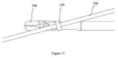
図11および12に示されるような他の実施形態では、ワイヤガイド部120の軸方向が鉗子アセンブリ部108の軸方向と平行ではない。
平行でないワイヤガイド部は、特定の外科的状況下でいくつかの利点をもたらすことができる。
これにより、鉗子アセンブリはガイドワイヤに対して特定の所望の角度で移動し、動作することができる。
In another embodiment,
In other embodiments,
In other embodiments,
In other embodiments,
In other embodiments,
In other embodiments, the axial direction of
Therefore, potential travel of the guidewire is limited only in the axial direction of
In other embodiments, the length of
In other embodiments, such as those shown in FIGS. 11 and 12, the axial direction of
Non-parallel wire guide sections can provide several advantages in certain surgical situations.
This allows the forceps assembly to move and operate at specific desired angles relative to the guidewire.
ワイヤガイド部120は上述の分離を回避するために、鉗子アセンブリ100の近位端104よりも鉗子アセンブリ100の遠位端102の近くに配置されているように構成される。
一般的に言えば、鉗子アセンブリ100の遠位端102に近づくほど、分離はより少なくなる。
他の実施形態ではワイヤガイド部120が鞘部110に配置されているが、依然として作業アセンブリ108の近くに配置されている。
他の実施形態では、ワイヤガイド部120が鉗子アセンブリ100の遠位端102から少なくとも3mmの位置に配置されている。
他の実施形態では、ワイヤガイド部120が作業アセンブリ108のコネクタ部の遠位端から少なくとも3mmの位置に配置されている。
他の実施形態において、ワイヤガイド部120は、作業部112上に配置されない。
他の実施形態では、所定の長さの鉗子アセンブリ100のみが、内視鏡を超えて延在するように構成され、ワイヤガイド部120は鉗子アセンブリ100の所定の長さ内に配置されている。
他の実施形態では、ワイヤガイド部120の一部が内視鏡内に配置されている。
Generally speaking, the closer you get to the
In other embodiments,
In other embodiments,
In other embodiments,
In other embodiments,
In other embodiments, only a length of
In other embodiments, a portion of
ワイヤガイド部がどこに配置されても、ワイヤガイド部120の位置は、鉗子カップ112の移動および/または開閉を妨げてはならない。 Wherever the wire guide portion is placed, the position of the
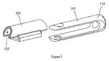
図3および4に示される実施形態において、ワイヤガイド部120は、アセンブリプロセスの間、コネクタ部114の少なくとも一部の上を滑るように構成される。
コネクタ部114は、フォークを備える。この実施形態では、コネクタ部114の少なくとも一部は、コネクタ部114のサイドアーム部115である。
しかしながら、ワイヤガイド部120がコネクタ部114の別の箇所又は全体を滑るこことも可能であると、当業者であれば理解することができる。
ワイヤガイド部120の組み立てられた位置において、作業アセンブリ108の他の構成要素はワイヤガイド部120のいかなる運動も制限し、スリップオン効果を達成する。
一方、コネクタ部114の外面およびワイヤガイド部120の内面122は、ガイドワイヤを誘導するためのチャネル部124を形成する。In the embodiment shown in FIGS. 3 and 4,
However, those skilled in the art will appreciate that the
In the assembled position of
Meanwhile, the outer surface of the
他の実施形態において、ワイヤガイド部120は、取り外し可能である。
図3、図5、および図6に示すワイヤガイド部120の利点の1つは、コネクタ部114を取り換える必要がないことである。
したがって、コネクタ部114は、通常の鉗子アセンブリと同じ設計で使用可能である。In other embodiments,
One advantage of the
Therefore, the
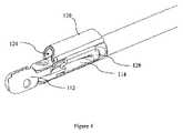
図4および図8~図10に示すような他の実施形態では、ワイヤガイド部がストッパ部128をさらに備える。
ストッパ部128は、ワイヤガイド部120の近位方向への移動を制限する。
他の実施形態では、ストッパ部128の少なくとも一部がコネクタ部114の作業チャネル部132に挿入される。
他の実施形態では、ストッパ部128の少なくとも一部が作業チャネル部132に正確に嵌合する。In other embodiments, such as those shown in FIGS. 4 and 8-10, the wire guide portion further comprises a
The
In other embodiments, at least a portion of
In other embodiments, at least a portion of
図6は、図3の別の例示的なワイヤガイド部120を示す。
図5はさらに別の例示的なワイヤガイド部120を示し、角度および半径の特徴を有する。
ワイヤガイド部の両端または両端の角度のついた特徴および/または半径は、ワイヤガイド部が挿入および抜去の間に十二指腸鏡を通って横断する間に、エレベータに捕捉される可能性を低減し得る。
ワイヤガイド部120の角度付き端部126は、約60度までである。
一実施形態では、角度126は約30度である。
一実施形態では、ワイヤガイド部の長さは約7mmである。
ワイヤガイド部の高さは約2mmである。
一実施形態では、ワイヤガイド部120が最大約0.035インチの直径を有する標準ガイドワイヤを通過させることができる。
当業者は、ワイヤガイド部の角度、長さ、および高さ、ならびにガイドワイヤの直径が上記の数に限定されないことを理解すべきである。
ここでは、内視鏡用途に適した、ワイヤガイド部の角度、長さ、高さ、またはガイドワイヤの直径を使用することができるFIG. 6 shows another exemplary
FIG. 5 shows yet another exemplary
The angled features and/or radii of the ends or ends of the wire guide portion may reduce the likelihood of elevator trapping while the wire guide portion traverses through the duodenoscope during insertion and withdrawal. .
The
In one embodiment,
In one embodiment, the length of the wire guide portion is approximately 7 mm.
The height of the wire guide portion is approximately 2 mm.
In one embodiment, the
Those skilled in the art should understand that the angle, length and height of the wire guide portion and the diameter of the guidewire are not limited to the above numbers.
Any wire guide angle, length, height, or guidewire diameter suitable for endoscopic applications can be used here.
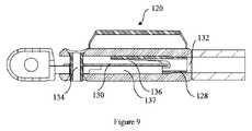
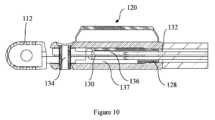
図9、図10、および図13に示されるような他の実施形態では、鉗子アセンブリ部108がスペーサ部130をさらに備える。
スペーサ部130は鉗子アセンブリ部108のピボット点134に連結されている。
スペーサ部130は鉗子アセンブリ部108の2つの可動アーム136、137を分離し、2つの可動アーム136、137がずれるのを防止する。
スペーサ部130の近位端はワイヤガイド部120が遠位方向に向かって移動するのを防止するために、ストッパ部128の凹部に挿入される。In other embodiments, such as those shown in FIGS. 9, 10 and 13, the
The proximal end of
本発明の別の実施形態は、図7に示されるように、鞘部110上に配置されたワイヤガイド部120である。コネクタ部114上の代わりに、ワイヤガイド部120が、ばねである鞘部110上に配置されている。
ワイヤガイド部120は、鞘部110の外壁に取り付けられる。
他の実施形態では、ワイヤガイド部120が鞘部110の遠位端111またはその近傍にある。
他の実施形態ではワイヤガイド部120の内面のみが、ガイドワイヤに沿って鉗子アセンブリ100を案内および制御するように構成された幾何学的形状を提供する。
他の実施形態では、鞘部110の外面およびワイヤガイド部120の内面が一緒になって、ガイドワイヤに沿って鉗子アセンブリ100を案内および制御するように構成される幾何学的形状を提供する。
ワイヤガイド部120の長さは、30cmまでの範囲とすることができる。
この実施形態では、ワイヤガイド部がばねである鞘部110と同じ材料で作られている。Another embodiment of the present invention is a
The
In other embodiments,
In other embodiments, only the inner surface of
In other embodiments, the outer surface of
The length of the
In this embodiment, the wire guide is made of the same material as the
ワイヤガイド部120は、鉗子アセンブリ100の他の構成要素に溶接、接着、オーバーモールド、または他の方法で接続されてもよい。
他の実施形態では、ワイヤガイド部120および鉗子アセンブリ100の1つ以上の構成要素が一体に作製される。
他の実施形態では、ワイヤガイド部120が図7に示されるように、ばねの巻き取りの間、ばね鞘部に捕捉される。
In other embodiments, one or more components of
In another embodiment, the
ワイヤガイド部120は、金属、プラスチック材料、ポリマー材料、または任意の他の適切な材料、またはそれらの任意の組み合わせから作製され得る。
他の実施形態において、ワイヤガイド部120は、ワイヤガイド(WIRE GUIDED)装置の他の構成要素と同じ材料で構成される。
他の実施形態では、ワイヤガイド部120がワイヤガイド(WIRE GUIDED)装置の他の構成要素とは異なる材料から作製される。
他の実施形態では、ワイヤガイド部120の内面はコーティングされる。
他の実施形態では、ワイヤガイド部120の内面が親水性ポリマーなどの親水性コーティングによってコーティングされる。
In other embodiments,
In other embodiments,
In other embodiments, the inner surface of
In other embodiments, the inner surface of
一般的な発明概念の様々な発明の態様、概念、および特徴が、様々な例示的な実施形態の文脈で本明細書で説明および例示されているが、これらの様々な態様、概念、および特徴は多くの代替的な実施形態において、個別に、またはそれらの様々な組合せおよびサブ組合せのいずれかで使用され得る。
本明細書において明確に除外されない限り、そのような組み合わせおよび部分的な組み合わせはすべて、一般的な発明概念の範囲内にあることが意図される。
さらに、本発明の様々な態様、概念、および特徴に関する様々な代替実施形態(代替材料、構造、構成、方法、回路、デバイス、および構成要素、形成、適合、および機能に関する代替など)を本明細書で説明することができるが、そのような説明は現在知られているか、または後に開発されるかにかかわらず、利用可能な代替実施形態の完全なまたは網羅的なリストであることを意図しない。
当業者は本発明の態様、概念、または特徴のうちの1つまたは複数を追加の実施形態に容易に採用し、そのような実施形態が本明細書で明示的に開示されていない場合であっても、一般的な本発明の概念の範囲内で使用することができる。
さらに、本発明のいくつかの特徴、概念、または態様が、好ましい配置または方法であるとして本明細書で説明され得るが、そのような説明は明示的にそのように述べられない限り、そのような特徴が必要または必要であることを示唆することを意図していない。
さらに、例示的または代表的な値および範囲は本開示の理解を助けるために含まれてもよいが、そのような値および範囲は限定的な意味で解釈されるべきではなく、そのように明示的に述べられた場合にのみ、臨界値または範囲であることが意図される。
さらに、様々な態様、特徴、および概念は本明細書では発明的であるか、または発明の一部を形成するものとして明確に識別され得るが、そのような識別は排他的であることを意図するものではなく、むしろ、そのようなものとして、または特定の発明の一部として明確に識別されることなく、本明細書で完全に説明される発明的態様、概念、および特徴が存在し得る。
例示的な方法またはプロセスの説明は、すべての場合に必要とされるものとしてすべてのステップを含むことに限定されず、また、ステップが提示される順序は明示的にそのように述べられない限り、必要または必要と解釈されるように提示される。Although various inventive aspects, concepts and features of the general inventive concept have been described and illustrated herein in the context of various exemplary embodiments, these various aspects, concepts and features may be used individually or in any of their various combinations and subcombinations in many alternative embodiments.
All such combinations and subcombinations are intended to be within the scope of the general inventive concept unless specifically excluded herein.
Moreover, various alternative embodiments of various aspects, concepts, and features of the present invention (such as alternative materials, structures, configurations, methods, circuits, devices, and components, formation, adaptation, and function alternatives) are described herein. However, such description is not intended to be an exhaustive or exhaustive list of alternative embodiments available, whether now known or later developed. .
One skilled in the art will readily adopt one or more of the aspects, concepts, or features of the present invention into additional embodiments, even if such embodiments are not expressly disclosed herein. can be used within the scope of the general inventive concept.
Moreover, while some feature, concept, or aspect of the invention may be described herein as being a preferred arrangement or method, such description is not intended to be such unless explicitly stated as such. It is not intended to imply that any particular feature is necessary or necessary.
Moreover, although exemplary or representative values and ranges may be included to aid in understanding the present disclosure, such values and ranges are not to be construed in a limiting sense and expressly Critical values or ranges are intended only where explicitly stated.
Moreover, although various aspects, features, and concepts may be expressly identified herein as inventive or forming part of the invention, such identification is intended to be exclusive. Rather, there may be inventive aspects, concepts, and features fully described herein without being clearly identified as such or as part of any particular invention. .
Descriptions of exemplary methods or processes are not limited to including all steps as required in all cases, nor is the order in which the steps are presented unless explicitly stated as such. , is presented as necessary or construed as necessary.
Claims (22)
Translated fromJapanese作業アセンブリと、
前記作業アセンブリに配置、接続されたワイヤガイド部と、
を備えるワイヤガイド(WIRE GUIDED)装置であって、
前記作業アセンブリは、
意図した組織に接触するよう構成された作業部と、
該作業部と前記鞘部とを接続するように構成されたコネクタ部と、
を有し、
前記ワイヤガイド部はガイドワイヤを通過させるように構成され、
前記ワイヤガイド部は前記作業アセンブリの遠位端から所定の距離に配置され、
前記ワイヤガイド部および前記ガイドワイヤは作業部の動作を妨げず、
前記ワイヤガイド部は、前記ワイヤガイド部の近位方向への移動を制限するストッパをさらに備え、
前記ストッパの少なくとも一部が、前記コネクタ部の作業チャネルに挿入される、
ワイヤガイド(WIRE GUIDED)装置。a sheath;
a working assembly;
a wire guide portion positioned and connected to the working assembly;
A WIRE GUIDED device comprising:
The working assembly includes:
a working portion configured to contact the intended tissue;
a connector portion configured to connect the working portion and the sheath portion;
has
The wire guide section is configured to allow a guide wire to pass through,
the wire guide portion is positioned a predetermined distance from the distal end of the working assembly;
The wire guide part and the guide wiredo not interfere with the operation of the working part,
The wire guide section further includes a stopper that restricts movement of the wire guide section in the proximal direction,
at least a portion of the stopper is inserted into a working channel of the connector portion;
WIRE GUIDED DEVICE.
請求項1に記載のワイヤガイド(WIRE GUIDED)装置。an inner surface of the wire guide portion configured and sized to limit potential movement of the guidewire to be substantially parallel to an axial direction of the working assembly;
The WIRE GUIDED device according to claim 1.
請求項4に記載のワイヤガイド(WIRE GUIDED)装置。an axial direction of the wire guide portion is substantially parallel to an axial direction of the working assembly;
The wire guide (WIRE GUIDED) device according to claim 4.
請求項1に記載のワイヤガイド(WIRE GUIDED)装置。an inner surface of the wire guide portion is configured and sized to limit potential movement of the guidewire from being non-parallel to an axial direction of the working assembly;
The WIRE GUIDED device according to claim 1.
請求項6に記載のワイヤガイド(WIRE GUIDED)装置。the axial direction of the wire guide portion is not parallel to the axial direction of the working assembly;
The WIRE GUIDED device according to claim 6.
請求項1に記載のワイヤガイド(WIRE GUIDED)装置。wherein the wire guide portion is positioned closer to a distal end of the working assembly than to a proximal end of the working assembly;
The WIRE GUIDED device according to claim 1.
請求項1に記載のワイヤガイド(WIRE GUIDED)装置。wherein the wire guide portion is positioned at least 3 mm from the distal end of the working assembly;
The WIRE GUIDED device according to claim 1.
請求項1に記載のワイヤガイド(WIRE GUIDED)装置。wherein the wire guide portion is positioned at least 3 mm from the distal end of the connector portion;
The WIRE GUIDED device according to claim 1.
前記コネクタ部の少なくとも一部に取り外し可能に係合する、
請求項1に記載のワイヤガイド(WIRE GUIDED)装置。The wire guide part is
removably engaging at least a portion of the connector portion;
The WIRE GUIDED device according to claim 1.
請求項11に記載のワイヤガイド(WIRE GUIDED)装置。the at least part of the connector portion is a side arm;
A WIRE GUIDED device according to claim11 .
請求項11に記載のワイヤガイド(WIRE GUIDED)装置。the working assembly limits any movement of the wire guide portion once the wire guide portion engages the connector portion;
A WIRE GUIDED device according to claim11 .
請求項1に記載のワイヤガイド(WIRE GUIDED)装置。the wire guide portion comprises an angled end;
The WIRE GUIDED device according to claim 1.
前記スペーサは、
前記鉗子アセンブリの旋回点に連結され、
前記鉗子アセンブリの2つの可動アームを分離して、前記2つの可動アームが脱臼するのを防止する、請求項2に記載のワイヤガイド(WIRE GUIDED)装置。the forceps assembly further includes a spacer;
The spacer is
coupled to a pivot point of the forceps assembly;
3. The WIRE GUIDED device of claim 2, wherein the two movable arms of the forceps assembly are separated to prevent dislocation of the two movable arms.
請求項15に記載のワイヤガイド(WIRE GUIDED)装置。a proximal end of the spacer is inserted into a recess of the stopper to preventdistal movement of the wire guide portion;
A WIRE GUIDED device according to claim15 .
請求項1に記載のワイヤガイド(WIRE GUIDED)装置。the wire guide portion is welded, glued, or overmolded to other components of the working assembly;
The WIRE GUIDED device according to claim 1.
請求項1に記載のワイヤガイド(WIRE GUIDED)装置。the wire guide portion and one or more components of the working assembly are integrally fabricated;
The WIRE GUIDED device according to claim 1.
請求項1に記載のワイヤガイド(WIRE GUIDED)装置。the wire guide portion is made of metal, plastic material, polymer material, or any combination thereof;
The WIRE GUIDED device according to claim 1.
請求項1に記載のワイヤガイド(WIRE GUIDED)装置。The wire guide portion is made of the same material as other components of the WIRE GUIDED device.
The WIRE GUIDED device according to claim 1.
請求項1に記載のワイヤガイド(WIRE GUIDED)装置。The inner surface of the wire guide portion is coated,
The WIRE GUIDED device according to claim 1.
請求項21に記載のワイヤガイド(WIRE GUIDED)装置。The inner surface of the wire guide portion is coated with a hydrophilic coating,
A WIRE GUIDED device according to claim21 .
Applications Claiming Priority (3)
| Application Number | Priority Date | Filing Date | Title |
|---|---|---|---|
| US201762561439P | 2017-09-21 | 2017-09-21 | |
| US62/561,439 | 2017-09-21 | ||
| PCT/US2018/052195WO2019060705A1 (en) | 2017-09-21 | 2018-09-21 | Wire guided device |
Publications (2)
| Publication Number | Publication Date |
|---|---|
| JP2020534080A JP2020534080A (en) | 2020-11-26 |
| JP7223750B2true JP7223750B2 (en) | 2023-02-16 |
Family
ID=63858082
Family Applications (1)
| Application Number | Title | Priority Date | Filing Date |
|---|---|---|---|
| JP2020516460AActiveJP7223750B2 (en) | 2017-09-21 | 2018-09-21 | WIRE GUIDED device |
Country Status (4)
| Country | Link |
|---|---|
| US (1) | US10779805B2 (en) |
| EP (2) | EP3684266B1 (en) |
| JP (1) | JP7223750B2 (en) |
| WO (1) | WO2019060705A1 (en) |
Families Citing this family (4)
| Publication number | Priority date | Publication date | Assignee | Title |
|---|---|---|---|---|
| CN110811702A (en)* | 2019-12-03 | 2020-02-21 | 贵州中医药大学第一附属医院 | Bronchoscope intelligence biopsy forceps |
| JP7504746B2 (en)* | 2020-10-02 | 2024-06-24 | レイクR&D株式会社 | Endoscopic treatment tools |
| JP7728682B2 (en)* | 2021-09-28 | 2025-08-25 | レイクR&D株式会社 | Endoscopic treatment tools |
| CN114795307A (en)* | 2022-05-06 | 2022-07-29 | 成都市第三人民医院 | Biopsy forceps capable of displaying forceps body position in real time |
Citations (5)
| Publication number | Priority date | Publication date | Assignee | Title |
|---|---|---|---|---|
| JP2002119514A (en) | 2000-10-18 | 2002-04-23 | Asahi Optical Co Ltd | Endoscope biopsy forceps |
| JP2006187446A (en) | 2005-01-06 | 2006-07-20 | Olympus Corp | Endoscopic instrument |
| JP2006263159A (en) | 2005-03-24 | 2006-10-05 | Olympus Corp | Endo-therapy accessory |
| CN204106056U (en) | 2014-08-06 | 2015-01-21 | 张修礼 | A kind of Transhepatic Cholangiobiopsy in Malignant Obstructive Jaundice pincers assembly |
| JP2016055176A (en) | 2014-09-11 | 2016-04-21 | パイン・メディカル・リミテッドPine Medical Limited | Drug coated balloon catheter and method of manufacture thereof |
Family Cites Families (9)
| Publication number | Priority date | Publication date | Assignee | Title |
|---|---|---|---|---|
| US3537456A (en)* | 1968-04-15 | 1970-11-03 | American Hospital Supply Corp | Bottom emptying drainage container for medical liquids |
| US5536248A (en)* | 1992-05-11 | 1996-07-16 | Arrow Precision Products, Inc. | Method and apparatus for electrosurgically obtaining access to the biliary tree and placing a stent therein |
| JP3174514B2 (en)* | 1996-11-27 | 2001-06-11 | 株式会社貝印刃物開発センター | Structure of the treatment section in the treatment tool for endoscope |
| CA2439536A1 (en)* | 2003-09-04 | 2005-03-04 | Jacek Krzyzanowski | Variations of biopsy jaw and clevis and method of manufacture |
| JP5019723B2 (en)* | 2005-06-30 | 2012-09-05 | オリンパスメディカルシステムズ株式会社 | Incision forceps |
| US20070244513A1 (en)* | 2006-04-14 | 2007-10-18 | Ethicon Endo-Surgery, Inc. | Endoscopic device |
| JP2007282847A (en)* | 2006-04-17 | 2007-11-01 | Olympus Medical Systems Corp | Flexible bipolar forceps |
| DE102012201081A1 (en)* | 2012-01-25 | 2013-07-25 | Herbert Maslanka | Surgical instrument |
| US10881831B2 (en)* | 2017-07-19 | 2021-01-05 | Hoya Corporation | Endoscopic basket delivery catheter |
- 2018
- 2018-09-21JPJP2020516460Apatent/JP7223750B2/enactiveActive
- 2018-09-21WOPCT/US2018/052195patent/WO2019060705A1/ennot_activeCeased
- 2018-09-21EPEP18786506.8Apatent/EP3684266B1/enactiveActive
- 2018-09-21EPEP21190691.2Apatent/EP3984467B1/enactiveActive
- 2018-09-21USUS16/138,227patent/US10779805B2/enactiveActive
Patent Citations (5)
| Publication number | Priority date | Publication date | Assignee | Title |
|---|---|---|---|---|
| JP2002119514A (en) | 2000-10-18 | 2002-04-23 | Asahi Optical Co Ltd | Endoscope biopsy forceps |
| JP2006187446A (en) | 2005-01-06 | 2006-07-20 | Olympus Corp | Endoscopic instrument |
| JP2006263159A (en) | 2005-03-24 | 2006-10-05 | Olympus Corp | Endo-therapy accessory |
| CN204106056U (en) | 2014-08-06 | 2015-01-21 | 张修礼 | A kind of Transhepatic Cholangiobiopsy in Malignant Obstructive Jaundice pincers assembly |
| JP2016055176A (en) | 2014-09-11 | 2016-04-21 | パイン・メディカル・リミテッドPine Medical Limited | Drug coated balloon catheter and method of manufacture thereof |
Also Published As
| Publication number | Publication date |
|---|---|
| US20190083072A1 (en) | 2019-03-21 |
| US10779805B2 (en) | 2020-09-22 |
| EP3684266A1 (en) | 2020-07-29 |
| EP3984467B1 (en) | 2024-03-06 |
| WO2019060705A1 (en) | 2019-03-28 |
| JP2020534080A (en) | 2020-11-26 |
| EP3984467A1 (en) | 2022-04-20 |
| EP3684266B1 (en) | 2021-08-11 |
Similar Documents
| Publication | Publication Date | Title |
|---|---|---|
| JP7223750B2 (en) | WIRE GUIDED device | |
| US6159162A (en) | Biopsy apparatus | |
| US11166736B2 (en) | Endoscopic stone-extraction device | |
| US9554819B2 (en) | Endoscope treatment tool | |
| US6273860B1 (en) | Biopsy apparatus | |
| US8469993B2 (en) | Endoscopic instruments | |
| US7927327B2 (en) | Medical instrument having an articulatable end effector | |
| EP2964104B1 (en) | Endoscopic biopsy needle with coil sheath | |
| JP2016505299A (en) | Device for minimally invasive delivery of therapeutic substances | |
| US20100298852A1 (en) | Endoscopic Scissors Instrument with Friction Enhancing Tissue Stops | |
| US20190282219A1 (en) | Biopsy forceps with serrated cutting jaws | |
| JP6310985B2 (en) | Endoscope cap with separable arm | |
| US20100298854A1 (en) | Endoscopic Instrument with Control Member Having Decreasing Torsional and Flexural Stiffness Along Its Length | |
| US10258355B2 (en) | Endoscopic stone-extraction device | |
| US20100298853A1 (en) | Endoscopic Instrument Having Rotatably Mounted End Effector Assembly | |
| WO2007010208A1 (en) | Surgical device for trans-nasal use | |
| JP4827879B2 (en) | Endoscope | |
| US12011187B2 (en) | Sheath for catheter length adjustment | |
| US20240423460A1 (en) | Medical systems, devices, and related methods |
Legal Events
| Date | Code | Title | Description |
|---|---|---|---|
| A621 | Written request for application examination | Free format text:JAPANESE INTERMEDIATE CODE: A621 Effective date:20210831 | |
| A977 | Report on retrieval | Free format text:JAPANESE INTERMEDIATE CODE: A971007 Effective date:20220708 | |
| A131 | Notification of reasons for refusal | Free format text:JAPANESE INTERMEDIATE CODE: A131 Effective date:20220712 | |
| A521 | Request for written amendment filed | Free format text:JAPANESE INTERMEDIATE CODE: A523 Effective date:20220930 | |
| TRDD | Decision of grant or rejection written | ||
| A01 | Written decision to grant a patent or to grant a registration (utility model) | Free format text:JAPANESE INTERMEDIATE CODE: A01 Effective date:20230117 | |
| A61 | First payment of annual fees (during grant procedure) | Free format text:JAPANESE INTERMEDIATE CODE: A61 Effective date:20230206 | |
| R150 | Certificate of patent or registration of utility model | Ref document number:7223750 Country of ref document:JP Free format text:JAPANESE INTERMEDIATE CODE: R150 |