Movatterモバイル変換


[0]ホーム

URL:


JP7223251B2 - Perforation forming device, post-processing device, image forming device, and image forming system - Google Patents

Perforation forming device, post-processing device, image forming device, and image forming system
Download PDF

Info

Publication number
JP7223251B2
JP7223251B2JP2018236067AJP2018236067AJP7223251B2JP 7223251 B2JP7223251 B2JP 7223251B2JP 2018236067 AJP2018236067 AJP 2018236067AJP 2018236067 AJP2018236067 AJP 2018236067AJP 7223251 B2JP7223251 B2JP 7223251B2
Authority
JP
Japan
Prior art keywords
sheet
pressing
perforation
pressing member
perforation forming
Prior art date
Legal status (The legal status is an assumption and is not a legal conclusion. Google has not performed a legal analysis and makes no representation as to the accuracy of the status listed.)
Active
Application number
JP2018236067A
Other languages
Japanese (ja)
Other versions
JP2020097082A (en
Inventor
智道 星野
朋裕 古橋
航 ▲高▼橋
道貴 鈴木
史晴 米山
信 日高
広樹 坂野
晶 國枝
賢裕 渡邉
拓哉 森永
陽介 原口
Current Assignee (The listed assignees may be inaccurate. Google has not performed a legal analysis and makes no representation or warranty as to the accuracy of the list.)
Ricoh Co Ltd
Original Assignee
Ricoh Co Ltd
Priority date (The priority date is an assumption and is not a legal conclusion. Google has not performed a legal analysis and makes no representation as to the accuracy of the date listed.)
Filing date
Publication date
Application filed by Ricoh Co LtdfiledCriticalRicoh Co Ltd
Priority to JP2018236067ApriorityCriticalpatent/JP7223251B2/en
Publication of JP2020097082ApublicationCriticalpatent/JP2020097082A/en
Application grantedgrantedCritical
Publication of JP7223251B2publicationCriticalpatent/JP7223251B2/en
Activelegal-statusCriticalCurrent
Anticipated expirationlegal-statusCritical

Links

Images

Landscapes

Description

Translated fromJapanese

この発明は、用紙などのシートにミシン目を形成するミシン目形成装置と、それを備えた後処理装置、画像形成装置、画像形成システムと、に関するものである。 The present invention relates to a perforation forming device for forming perforations on a sheet such as paper, a post-processing device, an image forming device, and an image forming system having the perforation forming device.

従来から、用紙などのシートにミシン目を形成するミシン目形成装置が知られている(例えば、特許文献1参照。)。 2. Description of the Related Art Conventionally, there has been known a perforation forming device that forms perforations in a sheet such as paper (for example, see Patent Document 1).

詳しくは、特許文献1におけるミシン目形成装置(横ミシン目加工装置)は、ウェブ(織物)にミシン目を形成する装置であって、ミシン刃が形成されたミシン胴と、ミシン刃を受けるミシン受胴と、が噛み合うように対向している。そして、ミシン胴とミシン受胴とを回転させながら、その間にウェブを走行させることで、ウェブにミシン目を形成している。
ここで、特許文献1には、ウェブにミシン目を良好に形成するために、ミシン胴とミシン受胴との軸間距離を調整する調整機構を設ける技術が開示されている。
Specifically, the perforation forming device (horizontal perforation processing device) inPatent Document 1 is a device for forming perforations on a web (woven fabric), and includes a sewing machine cylinder on which a perforating blade is formed, and a sewing machine that receives the perforating blade. They face each other so as to mesh with the receiving cylinder. Perforations are formed on the web by running the web between the sewing cylinder and the receiving cylinder while rotating them.
Here,Patent Document 1 discloses a technique of providing an adjusting mechanism for adjusting the inter-axis distance between a perforation cylinder and a perforation receiving cylinder in order to form perforations on a web satisfactorily.

特許文献1のミシン目形成装置は、ミシン刃部(ミシン胴)と押圧部材(ミシン受胴)との距離を調整する調整機構が設けられているため、ミシン刃部と押圧部材とが必要以上の力で圧接して機械的寿命が低下してしまう不具合が軽減される効果が、ある程度期待できる。
しかし、特許文献1のミシン目形成装置は、調整機構が複雑かつ大型であるため、装置全体が大型化、高コスト化してしまっていた。
Since the perforation forming device ofPatent Document 1 is provided with an adjustment mechanism for adjusting the distance between the perforation blade (sewing machine cylinder) and the pressing member (sewing machine receiving cylinder), the perforation blade and the pressing member are arranged more than necessary. It can be expected to some extent that the problem of reducing the mechanical life due to pressure contact with the force of .
However, the perforation forming device ofPatent Document 1 has a complicated adjustment mechanism and a large size.

この発明は、上述のような課題を解決するためになされたもので、装置が大型化、高コスト化することなく、機械的寿命が向上する、ミシン目形成装置、後処理装置、画像形成装置、及び、画像形成システム、を提供することにある。 DISCLOSURE OF THE INVENTION The present invention has been made to solve the above-described problems. , and an image forming system.

この発明における搬送装置は、シートにミシン目を形成するミシン目形成装置であって、所定方向に複数の尖状刃が並設されたミシン刃部と、前記ミシン刃部との間にシートを挟んだ状態で、当該シートを前記ミシン刃部に向けて押圧しながら前記所定方向に移動する押圧部材と、前記ミシン刃部に対する前記押圧部材の押圧方向の相対的な移動を制限する制限部材と、を備え、前記押圧部材は、前記所定方向に離れた位置に配置された支軸を中心に回動可能に支持されて、前記支軸の側から前記押圧部材の側に移動する方向を往路として、前記押圧部材の側から前記支軸の側に移動する方向を復路として、往復移動可能に構成され、前記押圧部材を前記往路と前記復路とのいずれか一方に移動させることで1枚のシートにミシン目を形成するか、前記押圧部材を前記往路と前記復路とを往復移動させることで1枚のシートにミシン目を形成するか、を切替可能に構成されたものである。A conveying device according to the present invention is a perforation forming device for forming perforations on a sheet, and a perforation blade portion having a plurality of pointed blades arranged side by side in a predetermined direction and a sheet between the perforation blade portion. A pressing member that moves in the predetermined direction while pressing the sheet toward the perforating blade in a pinched state, and a restricting member that restricts the relative movement of the pressing member in the pressing direction with respect to the perforating blade., wherein the pressing member is rotatably supported about a support shaft arranged at a position spaced apart in the predetermined direction, and moves in a direction from the support shaft side to the pressing member side. As an outward path, the direction of movement from the side of the pressing member to the side of the support shaft is used as a return path, and is configured to be capable of reciprocating movement. Forming perforations on one sheet or Forming perforations on one sheet by reciprocating the pressing member between the outward path and the return path can be switched.

本発明によれば、装置が大型化、高コスト化することなく、機械的寿命が向上する、ミシン目形成装置、後処理装置、画像形成装置、及び、画像形成システム、を提供することができる。 According to the present invention, it is possible to provide a perforation forming device, a post-processing device, an image forming device, and an image forming system that improve the mechanical life without increasing the size and cost of the device. .

この発明の実施の形態における画像形成システムを示す全体構成図である。1 is an overall configuration diagram showing an image forming system according to an embodiment of the present invention; FIG.ミシン目形成装置を示す構成図である。It is a block diagram which shows a perforation forming apparatus.押圧ローラが設置された押圧機構を示す斜視図である。FIG. 4 is a perspective view showing a pressing mechanism provided with a pressing roller;押圧ローラの移動が制限部材によって制限された状態を示す正面図である。FIG. 4 is a front view showing a state in which movement of the pressing roller is restricted by a restricting member;押圧ローラと、第1保持部材の支軸と、の位置関係を示す図である。It is a figure which shows the positional relationship of a press roller and the spindle of a 1st holding member.ミシン目形成装置のミシン目形成時の動作を示す図である。It is a figure which shows the operation|movement at the time of perforation formation of a perforation forming apparatus.ミシン目形成時のシートの動作を示す図である。FIG. 10 is a diagram showing the operation of a sheet when forming perforations;ミシン目形成装置を示すブロック図である。It is a block diagram which shows a perforation forming apparatus.ミシン目形成時の制御を示すフローチャートである。4 is a flow chart showing control during perforation formation.変形例1としての、ミシン目形成装置の動作を示す図である。It is a figure which shows operation|movement of the perforation forming apparatus as themodification 1. FIG.図10のミシン目形成装置を示すブロック図である。11 is a block diagram showing the perforation forming device of FIG. 10; FIG.図10のミシン目形成装置におけるミシン目形成時の制御を示すフローチャートである。11 is a flow chart showing control during perforation formation in the perforation forming apparatus of FIG. 10;変形例2としての、ミシン目形成装置の要部を示す図である。It is a figure which shows the principal part of the perforation forming apparatus as the modified example 2. FIG.変形例3としてのミシン目形成装置において、(A)往路時に押圧ローラとミシン刃部との接触部にかかる力を示す図と、(B)復路時に押圧ローラとミシン刃部との接触部にかかる力を示す図と、である。In the perforation forming device as Modified Example 3, (A) a diagram showing the force applied to the contact portion between the pressure roller and the perforation blade during the forward pass, and (B) the force applied to the contact portion between the pressure roller and the perforation blade during the return pass. 3A and 3B are diagrams showing the forces applied;変形例4としての、ミシン目形成装置の動作を示す図である。It is a figure which shows operation|movement of the perforation forming apparatus as themodification 4. FIG.図15のミシン目形成装置に対して、別形態のミシン目形成装置の動作を示す図である。It is a figure which shows operation|movement of the perforation forming apparatus of another form with respect to the perforation forming apparatus of FIG.変形例5としてのミシン目形成装置において、押圧ローラの移動が制限部材によって制限された状態を示す正面図である。FIG. 20 is a front view showing a state in which the movement of the pressing roller is restricted by a restricting member in the perforation forming device as Modified Example 5;変形例6としての、画像形成システムを示す概略図である。FIG. 11 is a schematic diagram showing an image forming system as Modified Example 6;別形態としての、画像形成装置を示す概略図である。FIG. 4 is a schematic diagram showing an image forming apparatus in another form;

以下、この発明を実施するための形態について、図面を参照して詳細に説明する。なお、各図中、同一又は相当する部分には同一の符号を付しており、その重複説明は適宜に簡略化ないし省略する。 BEST MODE FOR CARRYING OUT THE INVENTION Hereinafter, embodiments for carrying out the present invention will be described in detail with reference to the drawings. In each figure, the same or corresponding parts are denoted by the same reference numerals, and redundant description thereof will be appropriately simplified or omitted.

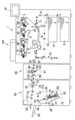
まず、図1にて、画像形成システム100における全体の構成・動作について説明する。
本実施の形態において、画像形成装置1は、ミシン目形成装置80と後処理装置50とが着脱可能に設置されていて、ミシン目形成装置80及び後処理装置50とともに1つの画像形成システム100を構成している。
ここで、画像形成システム100におけるミシン目形成装置80は、画像形成装置1から排出されたシートPに対して、搬送方向に直交する幅方向(図1の紙面垂直方向である。)にミシン目を形成するための装置である。
First, the overall configuration and operation of theimage forming system 100 will be described with reference to FIG.
In the present embodiment, theimage forming apparatus 1 has aperforation forming device 80 and apost-processing device 50 that are detachably installed. Configure.
Here, theperforation forming device 80 in theimage forming system 100 perforates the sheet P discharged from theimage forming device 1 in the width direction (perpendicular to the plane of FIG. 1) perpendicular to the conveying direction. It is an apparatus for forming

図1に示すように、画像形成装置1の中央上方には、中間転写ベルト8が設置されている。また、中間転写ベルト8に対向するように、各色(イエロー、マゼンタ、シアン、ブラック)に対応した感光体ドラム2Y、2M、2C、2K(作像部)が並設されている。さらに、中間転写ベルト8は、その下方で2次転写ローラ15(2次転写ベルト16)に圧接して、画像形成部としての2次転写ニップを形成している。 As shown in FIG. 1, anintermediate transfer belt 8 is installed above the center of theimage forming apparatus 1 . Further,photosensitive drums 2Y, 2M, 2C, and 2K (image forming units) corresponding to respective colors (yellow, magenta, cyan, and black) are arranged side by side so as to face theintermediate transfer belt 8 . Further, theintermediate transfer belt 8 is pressed against a secondary transfer roller 15 (secondary transfer belt 16) below to form a secondary transfer nip as an image forming portion.

図1に示すように、ブラックに対応した感光体ドラム2Kの周囲には、帯電部3、現像部4、クリーニング部5、除電部などが配置されている。そして、感光体ドラム2K上で、作像プロセス(帯電工程、露光工程、現像工程、転写工程、クリーニング工程、除電工程)がおこなわれる。この作像プロセスによって、感光体ドラム2Kの表面にブラック画像が形成されることになる。 As shown in FIG. 1, a charging section 3, a developingsection 4, a cleaning section 5, a neutralization section, and the like are arranged around thephotosensitive drum 2K corresponding to black. Then, an image forming process (charging process, exposure process, development process, transfer process, cleaning process, and static elimination process) is performed on thephotosensitive drum 2K. A black image is formed on the surface of thephotosensitive drum 2K by this image forming process.

なお、他の3つの感光体ドラム2Y、2M、2Cの周囲もほぼ同じように構成されていて、それぞれのトナー色に対応した画像が感光体ドラム2Y、2M、2Cの表面に形成される。以下、他の3つの感光体ドラム2Y、2M、2C上の作像プロセスの説明を適宜に省略して、ブラックに対応した作像プロセスのみの説明をおこなうことにする。 The surroundings of the other threephotosensitive drums 2Y, 2M, and 2C are configured in substantially the same manner, and images corresponding to respective toner colors are formed on the surfaces of thephotosensitive drums 2Y, 2M, and 2C. Hereinafter, description of the image forming process on the other threephotosensitive drums 2Y, 2M, and 2C will be appropriately omitted, and only the image forming process corresponding to black will be described.

感光体ドラム2Kは、メインモータによって図1の反時計方向に回転駆動される。そして、帯電部3の位置で、感光体ドラム2Kの表面が一様に帯電される(帯電工程である。)。
その後、感光体ドラム2Kの表面は、露光部7から発せられたレーザ光の照射位置に達して、この位置での幅方向(図1の紙面垂直方向であって、主走査方向である。)の露光走査によってブラックに対応した静電潜像が形成される(露光工程である。)。
Thephotosensitive drum 2K is rotated counterclockwise in FIG. 1 by a main motor. Then, the surface of thephotosensitive drum 2K is uniformly charged at the position of the charging section 3 (charging step).
After that, the surface of thephotosensitive drum 2K reaches the irradiation position of the laser beam emitted from the exposure unit 7, and the width direction (the direction perpendicular to the paper surface of FIG. 1 and the main scanning direction) at this position. An electrostatic latent image corresponding to black is formed by the exposure scanning of (exposure step).

その後、感光体ドラム2Kの表面は、現像部4との対向位置に達して、この位置で静電潜像が現像されて、ブラックのトナー像が形成される(現像工程である。)。
その後、感光体ドラム2Kの表面は、中間転写ベルト8及び1次転写ローラ6の対向位置に達して、この位置で感光体ドラム2Kの表面に形成されたトナー像が中間転写ベルト8の表面に1次転写される(1次転写工程である。)。このとき、感光体ドラム2K上には、僅かながら未転写トナーが残留する。
Thereafter, the surface of thephotosensitive drum 2K reaches a position facing the developingsection 4, and the electrostatic latent image is developed at this position to form a black toner image (developing step).
After that, the surface of thephotoreceptor drum 2K reaches a position facing theintermediate transfer belt 8 and theprimary transfer roller 6, and the toner image formed on the surface of thephotoreceptor drum 2K is transferred to the surface of theintermediate transfer belt 8 at this position. Primary transfer is performed (this is a primary transfer step). At this time, a small amount of untransferred toner remains on thephotosensitive drum 2K.

その後、感光体ドラム2Kの表面は、クリーニング部5との対向位置に達して、この位置で感光体ドラム2K上に残留した未転写トナーがクリーニングブレードによってクリーニング部5内に回収される(クリーニング工程である。)。
最後に、感光体ドラム2Kの表面は、除電部との対向位置に達して、この位置で感光体ドラム2K上の残留電位が除去される。
こうして、感光体ドラム2K上でおこなわれる、一連の作像プロセスが終了する。
After that, the surface of thephotoreceptor drum 2K reaches a position facing the cleaning section 5, and the untransferred toner remaining on thephotoreceptor drum 2K at this position is collected into the cleaning section 5 by the cleaning blade (cleaning process). is.).
Finally, the surface of thephotoreceptor drum 2K reaches a position facing the neutralization section, and the residual potential on thephotoreceptor drum 2K is removed at this position.
Thus, a series of image forming processes performed on thephotosensitive drum 2K are completed.

なお、上述した作像プロセスは、他の感光体ドラム2Y、2M、2Cの表面でも、ブラックの感光体ドラム2Kと同様におこなわれる。
そして、それぞれの感光体ドラム2Y、2M、2C、2Kの表面に形成された各色のトナー像が、中間転写ベルト8上に重ねて1次転写されることになる。こうして、中間転写ベルト8上にカラー画像が形成される。
The image forming process described above is performed on the surfaces of the otherphotosensitive drums 2Y, 2M, and 2C in the same manner as on the blackphotosensitive drum 2K.
Then, toner images of respective colors formed on the surfaces of the respectivephotosensitive drums 2Y, 2M, 2C, and 2K are superimposed on theintermediate transfer belt 8 and primarily transferred. A color image is thus formed on theintermediate transfer belt 8 .

その後、各色のトナー像が重ねて1次転写された中間転写ベルト8は、2次転写ローラ15(2次転写ベルト16)との対向位置に達する。この位置では、2次転写対向ローラ9が、2次転写ローラ15との間に中間転写ベルト8と2次転写ベルト16とを挟み込んで2次転写ニップ(画像形成部)を形成している。そして、中間転写ベルト8上に形成された4色のトナー像は、この2次転写ニップの位置に搬送された用紙等のシートP上に2次転写される(2次転写工程である。)。このとき、中間転写ベルト8には、シートPに転写されなかった未転写トナーが残留する。 After that, theintermediate transfer belt 8 on which the toner images of each color are superimposed and primarily transferred reaches a position facing the secondary transfer roller 15 (secondary transfer belt 16). At this position, the secondary transfer opposing roller 9 sandwiches theintermediate transfer belt 8 and thesecondary transfer belt 16 between itself and thesecondary transfer roller 15 to form a secondary transfer nip (image forming portion). Then, the four-color toner image formed on theintermediate transfer belt 8 is secondarily transferred onto the sheet P such as paper conveyed to the position of the secondary transfer nip (secondary transfer step). . At this time, untransferred toner that has not been transferred onto the sheet P remains on theintermediate transfer belt 8 .

その後、中間転写ベルト8は、中間転写クリーニング部の位置に達する。そして、この位置で、中間転写ベルト8の表面に付着した未転写トナーなどの付着物が除去される。
こうして、中間転写ベルト8上でおこなわれる、一連の転写プロセスが終了する。
After that, theintermediate transfer belt 8 reaches the position of the intermediate transfer cleaning section. At this position, deposits such as untransferred toner adhering to the surface of theintermediate transfer belt 8 are removed.
Thus, a series of transfer processes performed on theintermediate transfer belt 8 are completed.

ここで、図1を参照して、2次転写ニップの位置に搬送されるシートPは、画像形成装置1の下方に配設された給紙部10から、給紙ローラ11やレジストローラ12等が配置された搬送経路K1を経由して搬送されるものである。
詳しくは、給紙部10には、用紙などのシートPが複数枚重ねて収納されている。そして、給紙ローラ11が図1の反時計方向に回転駆動されると、一番上のシートPが搬送経路K1を経由してレジストローラ12のローラ間に向けて給送される。
Here, referring to FIG. 1, the sheet P conveyed to the position of the secondary transfer nip is fed from apaper feeding unit 10 arranged below theimage forming apparatus 1 to apaper feeding roller 11, aregistration roller 12, and the like. are conveyed via the conveying route K1 on which are arranged.
Specifically, in thepaper feeding unit 10, a plurality of sheets P such as paper are stacked and stored. Then, when thepaper feed roller 11 is driven to rotate counterclockwise in FIG. 1, the top sheet P is fed toward between the rollers of theregistration rollers 12 via the conveying path K1.

レジストローラ12に搬送されたシートPは、回転駆動を停止したレジストローラ12のローラニップの位置で一旦停止する。そして、中間転写ベルト8上のカラー画像にタイミングを合わせて、レジストローラ12が回転駆動されて、シートPが2次転写ニップに向けて搬送される。こうして、シートP上に、所望のカラー画像が転写される。 The sheet P conveyed to theregistration rollers 12 temporarily stops at the roller nip position of theregistration rollers 12 whose rotational driving is stopped. Then, theregistration roller 12 is rotationally driven in synchronization with the color image on theintermediate transfer belt 8, and the sheet P is conveyed toward the secondary transfer nip. A desired color image is transferred onto the sheet P in this manner.

その後、2次転写ニップの位置でカラー画像が転写されたシートPは、2次転写ベルト16によって搬送されて、2次転写ベルト16から分離された後に、搬送ベルト18によって定着部19の位置に搬送される。そして、この位置で、定着ベルト及び圧力ローラによる熱と圧力とにより、表面に転写されたカラー画像がシートP上に定着される(定着工程である。)。
その後、シートPは、排出搬送経路K2を経由して、排紙ローラ25によって画像形成装置1の外部へと排出される。
さらに、画像形成装置1から排出されたシートPは、ミシン目形成装置80の内部に搬送されて、ミシン目形成装置50内で必要に応じてミシン目が形成される。具体的に、ユーザーによって操作表示パネル40に予め「ミシン目形成処理」が選択されている場合に、ミシン目形成装置80によって、シートPの所望の位置にミシン目が形成される。なお、ミシン目形成装置80の構成・動作については後で詳しく説明する。
After that, the sheet P to which the color image has been transferred at the position of the secondary transfer nip is conveyed by thesecondary transfer belt 16 , separated from thesecondary transfer belt 16 , and then moved to the position of the fixing section 19 by the conveyingbelt 18 . be transported. At this position, the color image transferred to the surface is fixed onto the sheet P by heat and pressure from the fixing belt and the pressure roller (fixing process).
After that, the sheet P is discharged to the outside of theimage forming apparatus 1 by thedischarge rollers 25 via the discharge transport path K2.
Further, the sheet P discharged from theimage forming apparatus 1 is conveyed inside theperforation forming device 80 and perforations are formed in theperforation forming device 50 as necessary. Specifically, theperforation forming device 80 forms perforations at desired positions on the sheet P when the user selects “perforation forming process” on theoperation display panel 40 in advance. The configuration and operation of theperforation forming device 80 will be described later in detail.

その後、ミシン目形成装置80から排出されたシートPは、後処理装置50の内部に搬送されて、後処理装置50内で必要に応じてパンチ処理、綴じ処理などの後処理が施される。そして、後処理が施されたシートP(シート束PT)は、排出トレイ59に排出される。なお、後処理装置50の構成・動作については後で詳しく説明する。
こうして、画像形成装置1における、一連の画像形成プロセス(画像形成動作)が完了する。
After that, the sheet P discharged from theperforation forming device 80 is conveyed inside thepost-processing device 50 and subjected to post-processing such as punch processing and binding processing in thepost-processing device 50 as necessary. Then, the post-processed sheets P (sheet bundle PT) are discharged to thedischarge tray 59 . The configuration and operation ofpost-processing device 50 will be described later in detail.
Thus, a series of image forming processes (image forming operations) in theimage forming apparatus 1 are completed.

なお、図1を参照して、シートPの両面(オモテ面とウラ面とである。)へのプリントをおこなう「両面プリントモード」が選択されている場合には、オモテ面への定着工程が終了したシートPは、切替爪の動作により、上述した「片面プリントモード」が選択されているときのようにそのまま画像形成装置1から排出されることなく、反転搬送経路K3に導かれる。そして、反転搬送経路K3に導かれたシートPは、その搬送方向が反転された後に、切替爪の動作により両面搬送経路K4に導かれる。そして、両面搬送経路K4に導かれたシートPは、再び2次転写ニップ(画像形成部)の位置に向けて搬送される。そして、2次転写ニップの位置で先に説明したものと同様の画像形成プロセス(画像形成動作)によってシートPのウラ面への画像形成がおこなわれ、その後に定着部19での定着工程を経て、排出搬送経路K2を経由して、画像形成装置1から排出される。
なお、「片面プリントモード」、「両面プリントモード」は、ユーザーによる操作表示パネル40(画像形成装置1の外装部に設置されている。)の操作によって選択される。
Incidentally, referring to FIG. 1, when the "double-sided print mode" for printing on both sides of the sheet P (the front side and the back side) is selected, the fixing process on the front side is performed. The finished sheet P is guided to the reverse conveying path K3 by the operation of the switching claw without being discharged from theimage forming apparatus 1 as it is when the above-described "single-sided print mode" is selected. Then, the sheet P guided to the reversing conveying path K3 is guided to the double-sided conveying path K4 by the operation of the switching claw after the conveying direction is reversed. Then, the sheet P guided to the double-sided conveying path K4 is again conveyed toward the position of the secondary transfer nip (image forming portion). Then, at the position of the secondary transfer nip, an image is formed on the back side of the sheet P by the same image forming process (image forming operation) as described above. , is discharged from theimage forming apparatus 1 via the discharge transport path K2.
The "single-sided print mode" and the "double-sided print mode" are selected by the user's operation on the operation display panel 40 (installed on the exterior of the image forming apparatus 1).

以下、後処理装置50について詳述する。
まず、画像形成装置1からミシン目形成装置80を経由して搬送されたシートPは、入口ローラ51によって後処理装置50の内部に送入(搬送)される。
そして、操作表示パネル40にユーザーによって予め「通常処理モード」が選択されている場合には、切替爪57による搬送経路の切り替えによって、シートPは直線搬送経路K11を経由して排出ローラ58によって排出トレイ59上にそのまま排紙される。
その際、ユーザーによって操作表示パネル40に予め「パンチ処理」が付加的に選択されている場合には、シートPがパンチ処理部70を通過するときに、パンチ処理部70によってシートPにパンチ処理が施される。
また、ユーザーによって操作表示パネル40に予め「ソート処理」が付加的に選択されている場合には、シートPが排出ローラ58によって排出トレイ59上に排出されるときに、ソート処理部として機能する排出ローラ58が、シートPを仕分けるタイミングに合わせて幅方向に移動して、排出トレイ59に排出されるシートPにソート処理が施される。
Thepost-processing device 50 will be described in detail below.
First, the sheet P conveyed from theimage forming apparatus 1 via theperforation forming device 80 is fed (conveyed) into thepost-processing device 50 by theinlet rollers 51 .
When the user selects the "normal processing mode" on theoperation display panel 40 in advance, the sheet P is discharged by thedischarge rollers 58 via the straight conveying path K11 by switching the conveying path with the switchingclaw 57. The paper is discharged onto thetray 59 as it is.
At this time, if the user additionally selects “punch processing” on theoperation display panel 40 in advance, thepunch processing unit 70 punches the sheet P when the sheet P passes through thepunch processing unit 70 . is applied.
Further, when the user additionally selects "sort processing" on theoperation display panel 40 in advance, when the sheet P is ejected onto theejection tray 59 by theejection rollers 58, it functions as a sort processing section. Thedischarge rollers 58 move in the width direction in accordance with the timing of sorting the sheets P, and the sheets P discharged to thedischarge tray 59 are sorted.

これに対して、画像形成装置1の操作表示パネル40にユーザーによって予め「綴じ処理モード」が選択されている場合には、切替爪57による搬送経路の切り替えによって、シートPは綴じ処理用搬送経路K12を経由して積載部61に向けて搬送される。そして、シート揃え部60によって、積載部61に積載されたシートP(シート束PT)に対して、搬送方向と幅方向との揃え処理が施される。 On the other hand, when the user selects the "binding mode" in advance on theoperation display panel 40 of theimage forming apparatus 1, the switchingclaw 57 switches the conveying route, and the sheet P is moved to the binding processing conveying route. It is conveyed toward the stacking section 61 via K12. Then, thesheet aligning unit 60 aligns the sheets P (sheet bundle PT) stacked on the stacking unit 61 in the conveying direction and the width direction.

詳しくは、積載部61の載置面上にシートP(シート束PT)が載置されると、そのたびに、その上方に配置された叩きローラ56が回転軸を中心にして退避位置から最上方のシートPに当接する位置に回動して、叩きローラ56が図1の反時計方向に回転駆動されることで、そのシートPがエンドフェンス62に向けて搬送(移動)される。これにより、複数枚のシートP(シート束PT)の後端がエンドフェンス62に突き当たって、複数枚のシートP(シート束PT)の搬送方向の位置が揃えられることになる。
また、本実施の形態では、積載部61の載置面上にシートP(シート束PT)が載置されると、そのたびに、搬送ベルト65のベルト面に保持されたストッパ部64が、搬送ベルト65の図1の時計方向の走行によって、シートPの先端を押動するように移動して、そのシートPがエンドフェンス62に向けて搬送(移動)される。これにより、複数枚のシートP(シート束PT)の後端がエンドフェンス62に突き当たって、複数枚のシートP(シート束PT)の搬送方向の位置が揃えられることになる。
また、このようにシート束PTに対して搬送方向の揃え処理がおこなわれるとき、積載部61の幅方向両端部に設置されたサイドフェンス(ジョガーフェンス)が、積載部61上にシートPが載置されるたびに(又は、所望の枚数のシートPが積載された後に)、シートP(シート束PT)を挟み込むように幅方向(搬送方向に直交する方向であって、図1の紙面垂直方向である。)に移動して、シートP(シート束PT)の幅方向の位置が揃えられることになる。
More specifically, each time a sheet P (sheet bundle PT) is placed on the placement surface of the stacking unit 61, the hittingroller 56 arranged above the sheet P is moved from the retracted position to the maximum position around the rotation shaft. The sheet P is conveyed (moved) toward theend fence 62 by rotating to a position where it abuts on the upper sheet P and rotating the hittingroller 56 counterclockwise in FIG. As a result, the rear ends of the plurality of sheets P (sheet bundle PT) hit theend fence 62, and the positions of the plurality of sheets P (sheet bundle PT) in the conveying direction are aligned.
Further, in the present embodiment, each time a sheet P (sheet bundle PT) is placed on the placement surface of the stacking portion 61, thestopper portion 64 held on the belt surface of the conveyingbelt 65 1, the conveyingbelt 65 moves so as to push the leading edge of the sheet P, and the sheet P is conveyed (moved) toward theend fence 62 . As a result, the rear ends of the plurality of sheets P (sheet bundle PT) hit theend fence 62, and the positions of the plurality of sheets P (sheet bundle PT) in the conveying direction are aligned.
Further, when the sheet bundle PT is aligned in the conveying direction in this manner, the side fences (jogger fences) installed at both ends of the stacking section 61 in the width direction are used to prevent the sheets P from being stacked on the stacking section 61 . (or after a desired number of sheets P are stacked), the width direction (the direction orthogonal to the conveying direction and perpendicular to the plane of FIG. direction) to align the positions of the sheets P (sheet bundle PT) in the width direction.

そして、シート揃え装置60によって搬送方向と幅方向とがそれぞれ揃えられたシートP(シート束PT)の後端に対して、ステープラ75によって綴じ処理が施されることになる。
その後、綴じ処理が施されたシートP(シート束PT)は、放出爪としても機能するストッパ部64の排紙方向の移動によって載置面の傾斜に沿って斜め上方に移動して、排出搬送経路K13を通過した後に、排出ローラ58による搬送によって排出トレイ59に排紙される。
なお、綴じ処理モード時においても、ユーザーによって操作表示パネル40に予め「パンチ処理」が付加的に選択されている場合には、シートPがパンチ処理部70を通過するときに、パンチ処理部70によってシートPにパンチ処理が施される。
Then, the trailing edge of the sheet P (sheet bundle PT) aligned in the conveying direction and the width direction by thesheet alignment device 60 is subjected to binding processing by thestapler 75 .
Thereafter, the bound sheets P (sheet bundle PT) are moved obliquely upward along the inclination of the placement surface by the movement of thestopper portion 64, which also functions as a release claw, in the sheet ejection direction, and are ejected and conveyed. After passing through the path K13, the paper is discharged to thedischarge tray 59 by the conveyance by thedischarge rollers 58. FIG.
Even in the binding mode, if the user additionally selects "punching" on theoperation display panel 40 in advance, when the sheet P passes through thepunching section 70, the punchingsection 70 The sheet P is punched by the .

以下、図1~図9等を用いて、本実施の形態における画像形成システム100において特徴的な、ミシン目形成装置80について詳述する。
ミシン目形成装置80は、所定の搬送方向(図2の紙面垂直方向であって、図4の左右方向である。)に搬送されるシートPに対して、幅方向(搬送方向に直交する方向である。)に沿うようにミシン目を形成する装置である。
図1を参照して、装置内に搬入されたシートPは、ミシン目形成装置主部81まで搬送されて、その位置で停止した状態でミシン目形成装置主部81によって幅方向にミシン目が形成されることになる。
Theperforation forming device 80, which is characteristic of theimage forming system 100 according to the present embodiment, will be described in detail below with reference to FIGS. 1 to 9 and the like.
Theperforation forming device 80 moves the sheet P conveyed in a predetermined conveying direction (perpendicular to the plane of FIG. 2 and the left-right direction in FIG. 4) in the width direction (the direction orthogonal to the conveying direction). It is a device that forms perforations along the line.
Referring to FIG. 1, the sheet P carried into the apparatus is conveyed to the perforation forming devicemain section 81, and is perforated in the width direction by the perforation forming devicemain section 81 while stopped at that position. will be formed.

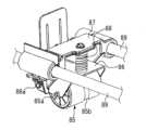
図2~図4等に示すように、ミシン目形成装置主部81(ミシン目形成装置80)は、ミシン刃部82、押圧部材としての押圧ローラ85を備えた押圧機構85~88、押圧ローラ85(押圧機構85~88)を幅方向に移動する移動機構89~93、ミシン目形成時における押圧ローラ85とミシン刃部82との位置関係を定めるための制限部材83、退避台94、などで構成されている。 As shown in FIGS. 2 to 4 and the like, a perforation forming device main portion 81 (perforation forming device 80) includes aperforation blade portion 82, pressingmechanisms 85 to 88 having apressing roller 85 as a pressing member, and a pressing roller. Movingmechanisms 89 to 93 for moving 85 (pressingmechanisms 85 to 88) in the width direction, a limitingmember 83 for determining the positional relationship between thepressing roller 85 and theperforating blade portion 82 when forming perforations, a retraction table 94, and the like. consists of

ミシン刃部82は、所定方向(図2の左右方向であって、図4の紙面垂直方向であって、幅方向である。)に複数の尖状刃が並設されている。複数の尖状刃は、その刃先82aが上方を向くように配置され、通紙可能な最大サイズのシートPの幅方向の範囲と同等の範囲(又は、それよりも僅かに広い範囲)にわたって配列されている。ミシン刃部82は、高硬度の金属材料で形成されている。 Theperforating blade portion 82 has a plurality of pointed blades arranged side by side in a predetermined direction (horizontal direction in FIG. 2, vertical direction in FIG. 4, and width direction). The plurality of pointed blades are arranged so that theirblade edges 82a face upward, and are arranged over a range equivalent to (or slightly wider than) the range in the width direction of the sheet P of the maximum size that can be passed. It is The perforatingblade portion 82 is made of a high-hardness metal material.

押圧ローラ85は、ミシン刃部82との間にシートPを挟んだ状態で、そのシートPをミシン刃部82に向けて押圧しながら所定方向(幅方向)に移動する押圧部材として機能するものである。
本実施の形態において、押圧ローラ85は、樹脂材料からなるホイール部を覆うように、ゴム材料(又は、樹脂材料)からなる外周部が形成されたものである。そして、押圧ローラ85は、移動機構89~93の駆動によって、幅方向両端部にそれぞれ設けられた退避台94の間を、所定方向(幅方向)に沿うように回転しながら所定方向(幅方向)に移動する。
なお、図4等に示すように、押圧ローラ85には、大径部85cと小径部85b(溝部)とが設けられているが、これについては後で詳しく説明する。
Thepressing roller 85 functions as a pressing member that moves in a predetermined direction (width direction) while pressing the sheet P toward theperforating blade portion 82 while sandwiching the sheet P between itself and theperforating blade portion 82 . is.
In this embodiment, the pressingroller 85 has an outer peripheral portion made of a rubber material (or a resin material) so as to cover a wheel portion made of a resin material. Then, the pressingroller 85 is driven by the movingmechanisms 89 to 93 to rotate in a predetermined direction (width direction) between the evacuation bases 94 provided at both ends in the width direction. ).
As shown in FIG. 4 and the like, the pressingroller 85 is provided with a large-diameter portion 85c and a small-diameter portion 85b (grooves), which will be described later in detail.

図3、図4等に示すように、押圧機構は、上述した押圧ローラ85の他に、第1保持部材86(第1ブラケット)、第2保持部材87(第2ブラケット)、圧縮スプリング88(付勢部材)、などで構成されている。
第1保持部材86は、板金に種々の曲げ加工を施して形成したブラケットであって、押圧ローラ85を直接的に回転可能に保持するものである。詳しくは、押圧ローラ85の両端からそれぞれ突出する軸部85aが、軸受を介して(又は、直接的に)第1保持部材86の穴部に挿入されている。
第2保持部材87は、樹脂成型によって(又は、板金に種々の曲げ加工を施して)形成したブラケットであって、第1保持部材86を支軸86a(回転軸)を中心に回動可能に保持するものである。詳しくは、第1保持部材86と第2保持部材87とのそれぞれの両端に形成された穴部に、支軸86aが挿通されている。
また、第2保持部材87は、装置の幅方向両端に設置された側板95の間に橋設されたガイドレール89に、スライド移動可能に保持されている。詳しくは、第2保持部材87の両端にそれぞれ形成された穴部に、ガイドレール89が挿通されている。
圧縮スプリング88は、その一端側が第1保持部材86に接続され、その他端側が第2保持部材87に接続されている。この圧縮スプリング88のスプリング力が、押圧ローラ85を押圧方向(シートPを押圧する方向であって、下方である。)に付勢する力となる。
このように、本実施の形態において、押圧ローラ85(押圧部材)は、第2保持部材87(ミシン目形成装置80)において、支軸86aを中心に回動可能に支持されていることになる。
As shown in FIGS. 3 and 4, the pressing mechanism includes a first holding member 86 (first bracket), a second holding member 87 (second bracket), a compression spring 88 ( biasing member), etc.
The first holdingmember 86 is a bracket formed by bending a sheet metal in various ways, and directly holds thepressing roller 85 so as to be rotatable. Specifically, theshaft portions 85a protruding from both ends of thepressing roller 85 are inserted into the holes of the first holdingmember 86 via bearings (or directly).
The second holdingmember 87 is a bracket formed by resin molding (or by bending a sheet metal in various ways), and the first holdingmember 86 is rotatable about asupport shaft 86a (rotating shaft). to hold. Specifically, thesupport shafts 86a are inserted through holes formed at both ends of the first holdingmember 86 and the second holdingmember 87, respectively.
The second holdingmember 87 is slidably held byguide rails 89 bridged betweenside plates 95 installed at both ends in the width direction of the apparatus. Specifically, the guide rails 89 are inserted through holes formed at both ends of the second holdingmember 87 .
Thecompression spring 88 has one end connected to the first holdingmember 86 and the other end connected to the second holdingmember 87 . The spring force of thecompression spring 88 acts as a force that urges thepressing roller 85 in the pressing direction (the direction in which the sheet P is pressed, which is downward).
Thus, in the present embodiment, the pressing roller 85 (pressing member) is rotatably supported by the second holding member 87 (perforation forming device 80) about thesupport shaft 86a. .

移動機構は、押圧ローラ85(押圧機構85~88)を幅方向に移動する機構であって、ガイドレール89、タイミングベルト90、駆動モータ91、プーリ92、93等で構成されている。
ガイドレール89は、上述したように、押圧機構85~88を幅方向にスライド移動可能に保持している。
タイミングベルト90は、装置の幅方向両端部にそれぞれ保持されたプーリ92、93に巻架されている。2つのプーリのうち一方のプーリ92には、駆動モータ91の駆動ギアに噛合する従動ギアが同軸上に一体的に形成されている。また、タイミングベルト90の一部が、押圧機構の第2保持部材87に固定して接続されている。
駆動モータ91は、正逆双方向回転型のモータであって、押圧ローラ85(押圧機構85~88)を、図2の左方から右方へ向かう往路を移動させたり、図2の右方から左方へ向かう復路を移動させたりすることができる。
The moving mechanism is a mechanism for moving the pressing roller 85 (pressingmechanisms 85 to 88) in the width direction, and is composed of aguide rail 89, atiming belt 90, adrive motor 91, pulleys 92 and 93, and the like.
As described above, theguide rail 89 holds thepressing mechanisms 85 to 88 so as to be slidable in the width direction.
Thetiming belt 90 is wound around pulleys 92 and 93 respectively held at both ends in the width direction of the device. Onepulley 92 of the two pulleys is coaxially and integrally formed with a driven gear that meshes with the drive gear of thedrive motor 91 . A portion of thetiming belt 90 is fixedly connected to the second holdingmember 87 of the pressing mechanism.
Thedrive motor 91 is a bi-directional rotating motor, and moves the pressing roller 85 (pressingmechanisms 85 to 88) in an outward path from left to right in FIG. It is possible to move the return path from to the left.

このような構成により、制御部125の制御によって駆動モータ91が正方向に駆動されると、図2の左方の退避台94(ホームポジション)上に退避していた押圧機構85~88が右方の退避台94に向けて移動することになる。このとき、押圧ローラ85は、ミシン刃部82との間に挟まれたシートPをミシン刃部82に押し付けながら幅方向に移動する。これにより、ミシン刃部82の複数の尖状刃が順次シートPに突き刺さり、シートPの幅方向全域にミシン目が形成されることになる。
これに対して、制御部125の制御によって駆動モータ91が逆方向に駆動されると、ミシン目形成処理を終えて図2の右方の退避台94上に退避していた押圧機構85~88が、次のミシン目形成処理に備えて、左方の退避台94(ホームポジション)に向けて移動することになる。
With such a configuration, when thedrive motor 91 is driven in the forward direction under the control of thecontrol unit 125, thepressing mechanisms 85 to 88 that have been retracted onto the retraction base 94 (home position) on the left side in FIG. It moves toward the evacuation table 94 on the one side. At this time, the pressingroller 85 moves in the width direction while pressing the sheet P sandwiched between itself and theperforation blade portion 82 against theperforation blade portion 82 . As a result, the plurality of pointed blades of theperforating blade portion 82 sequentially pierce the sheet P, and perforations are formed across the width of the sheet P. As shown in FIG.
On the other hand, when thedrive motor 91 is driven in the reverse direction under the control of thecontrol unit 125, thepressing mechanisms 85 to 88 that have been retracted onto the retraction table 94 on the right side in FIG. is moved toward the left retraction table 94 (home position) in preparation for the next perforation forming process.

なお、本実施の形態では、押圧ローラ85(押圧機構85~88)が往路を移動するときに、シートPに対してミシン目形成処理をおこなうように構成したが、押圧ローラ85が復路を移動するときにミシン目形成処理をおこなうように構成することもできるし、押圧ローラ85が往路を移動するときにも復路を移動するときにもミシン目形成処理をおこなうように構成することもできる。
また、本実施の形態では、双方の退避台94の位置に、押圧機構85~88を光学的に検知するセンサが設置されていて、そのセンサの検知結果に基づいて制御部125によって駆動モータ91が制御される。そして、押圧機構85~88の位置を認識しながら、上述した押圧機構85~88の往復移動がおこなわれることになる。
In this embodiment, the sheet P is perforated when the pressing roller 85 (pressingmechanisms 85 to 88) moves in the outward path. It is also possible to configure so that the perforation forming process is performed when thepressure roller 85 moves on the outward path and when thepressure roller 85 moves on the return path.
Further, in the present embodiment, sensors for optically detecting thepressing mechanisms 85 to 88 are installed at the positions of bothevacuation bases 94, and thedrive motor 91 is controlled by thecontrol unit 125 based on the detection results of the sensors. is controlled. Then, while recognizing the positions of thepressing mechanisms 85 to 88, the above-described reciprocating movements of thepressing mechanisms 85 to 88 are performed.

ここで、本実施の形態におけるミシン目形成装置80には、ミシン刃部82に対する押圧ローラ85(押圧部材)の押圧方向の相対的な移動を制限する制限部材83が設けられている。
詳しくは、図2、図4を参照して、制限部材83は、幅方向に延在するミシン刃部82を搬送方向上流側と搬送方向下流側とで幅方向にわたって挟むように形成された一対の板金である。制限部材83を構成する上流側の板金は、その上端部が上流側に水平方向に広がるように曲げ加工が施されている。同様に、制限部材83を構成する下流側の板金は、その上端部が下流側に水平方向に広がるように曲げ加工が施されている。そして、これらの上端部が、押圧ローラ85に当接することで、押圧ローラ85の下方(押圧方向)への移動が制限されることになる。すなわち、押圧ローラ85は、先に説明した圧縮スプリング88のスプリング力(及び、第1保持部材86や押圧ローラ85の自重)によって下方に付勢されるが、押圧ローラ85が制限部材83に当接する位置で、押圧ローラ85の押圧方向の位置が定められることになる(それ以上、下方に移動しないことになる)。
Here, theperforation forming device 80 according to the present embodiment is provided with a restrictingmember 83 that restricts the relative movement of the pressing roller 85 (pressing member) with respect to theperforating blade portion 82 in the pressing direction.
Specifically, referring to FIGS. 2 and 4, the restrictingmember 83 is a pair of restrictingmembers 83 formed so as to sandwich theperforating blade portion 82 extending in the width direction between the upstream side in the conveying direction and the downstream side in the conveying direction across the width direction. sheet metal. The upstream sheet metal that constitutes the restrictingmember 83 is bent so that its upper end extends horizontally toward the upstream side. Similarly, the downstream sheet metal forming the restrictingmember 83 is bent so that the upper end of the plate expands in the downstream direction in the horizontal direction. The upper end portions of these contact thepressing roller 85, thereby restricting the downward movement of the pressing roller 85 (in the pressing direction). That is, the pressingroller 85 is urged downward by the spring force of thecompression spring 88 described above (and the weight of the first holdingmember 86 and the pressing roller 85). At the contact position, the position of thepressing roller 85 in the pressing direction is determined (there is no further downward movement).

このように、制限部材83は、押圧方向に移動する押圧ローラ85(押圧部材)に当接することにより、押圧時におけるミシン刃部82に対する押圧ローラ85の押圧方向の位置を定めるものである。
換言すると、制限部材83は、ミシン刃部82に対する押圧ローラ85の押圧方向の相対的な位置を保持する手段として機能することになる。
In this manner, the restrictingmember 83 abuts on the pressing roller 85 (pressing member) moving in the pressing direction, thereby determining the position of thepressing roller 85 in the pressing direction against the sewingmachine blade portion 82 at the time of pressing.
In other words, the limitingmember 83 functions as means for holding the relative position of thepressing roller 85 with respect to the sewingmachine blade portion 82 in the pressing direction.

このように、本実施の形態では、ミシン刃部82に対する押圧ローラ85の押圧方向の移動を制限する制限部材83を設けているため、ミシン刃部82と押圧ローラ85とが必要以上の力で圧接して機械的寿命が低下してしまう不具合が軽減されることになる。具体的に、ミシン刃部82の尖状刃の刃先82aが丸まったり欠けたりする不具合や、押圧ローラ85の表面が大きく傷ついたり剥がれ落ちたりする不具合が軽減されることになる。
また、制限部材83は簡易な構成のものであって、制限部材83を設けることで押圧ローラ85の押圧方向の移動を簡単に制限することができるため、ミシン刃部82と押圧ローラ85との距離を調整するための複雑な調整機構を設ける場合に比べて、装置を小型化、低コスト化することができる。
As described above, in this embodiment, since the restrictingmember 83 is provided for restricting the movement of thepressure roller 85 with respect to theperforating blade 82 in the pressing direction, the perforatingblade 82 and thepressure roller 85 are pushed with more force than necessary. This reduces the problem of reduced mechanical life due to pressure contact. Specifically, problems such as thecutting edge 82a of the sharp blade of the sewingmachine blade portion 82 being rounded or chipped, and the problem that the surface of thepressure roller 85 being severely damaged or peeled off can be reduced.
Further, the restrictingmember 83 has a simple structure, and by providing the restrictingmember 83, it is possible to easily restrict the movement of thepressing roller 85 in the pressing direction. Compared to the case of providing a complicated adjustment mechanism for adjusting the distance, the size and cost of the device can be reduced.

ここで、図4等に示すように、本実施の形態における押圧ローラ85は、一対の大径部85cと、小径部85b(溝部)と、が設けられている。
小径部85bは、上述した制限部材83による制限によって、複数の尖状刃(刃先82a)に接しないように対向するものである。すなわち、押圧ローラ85が制限部材83に当接した状態のとき、ミシン刃部82の尖状刃の刃先82aと、小径部85bと、は接することなく、それらの間に隙間が形成されることになる。
一対の大径部85cは、小径部85bを間に挟むように形成されている。すなわち、大径部85cの中央部に小径部85bが溝のように形成されている。そして、一対の大径部85cは、押圧ローラ85による押圧によって、複数の尖状刃(刃先82a)に接することなく、シートPに接することになる。すなわち、一対の大径部85cは、シートPを介して、制限部材83の上端部に接することになる。そして、一対の大径部85cの間で、ミシン刃部82の尖状刃がシートPを突き抜くことで、シートPにミシン目(貫通穴)が形成されることになる。
Here, as shown in FIG. 4 and the like, the pressingroller 85 in the present embodiment is provided with a pair of large-diameter portions 85c and a small-diameter portion 85b (grooves).
The small-diameter portion 85b faces the plurality of sharp blades (cutting edges 82a) so as not to come into contact with them due to the limitation by the above-described limitingmember 83. As shown in FIG. In other words, when thepressing roller 85 is in contact with the restrictingmember 83, thecutting edge 82a of the sharp blade of thesewing machine blade 82 and the small-diameter portion 85b are not in contact with each other, and a gap is formed between them. become.
The pair oflarge diameter portions 85c are formed so as to sandwich thesmall diameter portion 85b therebetween. That is, thesmall diameter portion 85b is formed like a groove in the central portion of thelarge diameter portion 85c. The pair of large-diameter portions 85c are pressed by the pressingroller 85 so as to contact the sheet P without contacting the plurality of pointed blades (the blade edges 82a). That is, the pair oflarge diameter portions 85c are in contact with the upper end portion of the restrictingmember 83 with the sheet P interposed therebetween. Perforations (through holes) are formed in the sheet P by the sharp blades of theperforating blade portion 82 piercing the sheet P between the pair of large-diameter portions 85c.

このように、押圧ローラ85は、ミシン形成処理時にミシン刃部82に当接しないように、制限部材83に当接することになる。これにより、上述したミシン刃部82や押圧ローラ85の機械的寿命(耐久性)が向上する効果が、さらに発揮されることになる。
なお、大径部85cと小径部85bとは、いずれも、同じ軸部85aを中心に形成されている。これにより、ミシン目形成処理時に押圧ローラ85が回転しながら幅方向に移動しても、ミシン刃部82の刃先82aが押圧ローラ85に接触することはない。
In this manner, the pressingroller 85 abuts against the restrictingmember 83 so as not to abut against the perforatingblade portion 82 during the perforating process. As a result, the effect of improving the mechanical life (durability) of theperforating blade portion 82 and thepressing roller 85 described above is further exhibited.
Both the large-diameter portion 85c and the small-diameter portion 85b are formed around thesame shaft portion 85a. As a result, even if thepressure roller 85 rotates and moves in the width direction during the perforation forming process, thecutting edge 82 a of theperforation blade portion 82 does not come into contact with thepressure roller 85 .

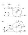
ここで、図5(A)(及び、図3)を参照して、本実施の形態におけるミシン目形成装置80(押圧機構85~88)は、ミシン刃部82における複数の尖状刃の刃先82aから支軸86aまでの押圧方向の距離をMとして、複数の尖状刃の刃先82aから押圧ローラ85の重心(軸部85a)までの押圧方向の距離をNとしたときに、
M≧N
なる関係が成立するように構成されている。
図5(A)、(B)に示すように、移動機構89~93により押圧ローラ85(押圧機構85~88)が矢印X方向に移動しているとき、押圧ローラ85の回動の中心となる支軸86aには、ガイドレール89を介して矢印F1方向の駆動力が作用する。
このとき、図5(B)に示すように、支軸86aと軸部85aとの位置関係において、M´<Nなる関係が成立する場合には、押圧ローラ85には、ミシン刃部82から離れる方向のモーメントが作用することになる。そのため、押圧ローラ85が尖状刃に乗り上げるときに、押圧ローラ85が跳ね上がってしまう可能性がある。そのような場合には、押圧ローラ85による押圧力が低下して、シートPに良好なミシン目を形成することができなってしまう。
これに対して、本実施の形態では、図5(A)に示すように、支軸86aと軸部85aとの位置関係において、M≧Nなる関係が成立するため、押圧ローラ85には、ミシン刃部82に近づく方向のモーメントが作用することになる。そのため、押圧ローラ85が尖状刃に乗り上げるときに、押圧ローラ85が跳ね上がりにくくなる。したがって、押圧ローラ85による押圧力が低下することなく、シートPに良好なミシン目を形成することができる。
Here, referring to FIG. 5A (and FIG. 3), perforation forming device 80 (pressingmechanisms 85 to 88) according to the present embodiment includes cutting edges of a plurality of pointed blades in perforatingblade portion 82. When the distance in the pressing direction from 82a to thesupport shaft 86a is M, and the distance in the pressing direction from thecutting edge 82a of the plurality of pointed blades to the center of gravity (shaft portion 85a) of thepressing roller 85 is N,
M≧N
It is configured so that the following relationship is established.
As shown in FIGS. 5A and 5B, when the pressing roller 85 (pressingmechanisms 85 and 88) is moved in the direction of the arrow X by the movingmechanisms 89 to 93, the rotation center of thepressing roller 85 and A driving force in the direction of the arrow F1 acts on the supportingshaft 86a through theguide rail 89. As shown in FIG.
At this time, as shown in FIG. 5(B), in the positional relationship between thesupport shaft 86a and theshaft portion 85a, when the relationship of M'<N is established, thepressure roller 85 does not move from theperforating blade portion 82. A moment in the direction of separation will act. Therefore, when thepressure roller 85 rides on the pointed blade, there is a possibility that thepressure roller 85 jumps up. In such a case, the pressing force of thepressing roller 85 is reduced, and good perforations on the sheet P cannot be formed.
On the other hand, in the present embodiment, as shown in FIG. 5A, the positional relationship between thesupport shaft 86a and theshaft portion 85a is such that M≧N. A moment acts in the direction of approaching theperforating blade portion 82 . Therefore, when thepressure roller 85 rides on the pointed blade, thepressure roller 85 is less likely to spring up. Therefore, it is possible to form good perforations on the sheet P without lowering the pressing force of thepressing roller 85 .

ここで、図6等を参照して、本実施の形態において、制限部材83は、押圧方向に対して正逆方向(図6の上下方向である。)に移動可能に構成されている。
そして、シートPにミシン目を形成することなくシートPを搬送するときには、図6(A)、(D)に示すように、そのシートPが複数の尖状刃(ミシン刃部82)に接しないように、制限部材83が押圧方向の逆方向(図6の上方である。)に移動する。そして、そのように上方に移動した制限部材83(その上端部が尖状刃の刃先82aよりも上方に移動した制限部材83である。)が、シートPの搬送を案内する搬送ガイド板として機能することになる。すなわち、非ミシン目形成処理時には、制限部材83が尖状刃の刃先82aを覆うように上方に移動して、その位置を通過するシートPは、搬送ガイド板として機能する制限部材83にガイドされながら、その位置を通過していくことになる。なお、非ミシン目形成処理時は、ユーザーによる操作表示パネル40の操作によって「ミシン目形成処理」が選択されていない場合の他、「ミシン目形成処理」が選択されている場合における処理前後の状態も含むものである。
これに対して、シートにミシン目を形成するときには、図6(B)、(C)に示すように、搬送停止された状態のシートPが複数の尖状刃(ミシン刃部82)に接するように、制限部材83が押圧方向の正方向(下方)に移動する。そして、そのように下方に移動した制限部材83(その上端部が尖状刃の刃先82aよりも下方に移動した制限部材83である。)によって制限された状態で、押圧ローラ85がシートPを押圧することになる。
Here, referring to FIG. 6 and the like, in the present embodiment, restrictingmember 83 is configured to be movable in forward and reverse directions (vertical direction in FIG. 6) with respect to the pressing direction.
When conveying the sheet P without forming perforations on the sheet P, as shown in FIGS. In order to prevent this, the restrictingmember 83 moves in the direction opposite to the pressing direction (upward in FIG. 6). Then, the restrictingmember 83 moved upward in this way (the upper end of the restrictingmember 83 is the restrictingmember 83 moved above thecutting edge 82a of the pointed blade) functions as a conveying guide plate that guides the conveying of the sheet P. will do. That is, during the non-perforation forming process, the restrictingmember 83 moves upward so as to cover thecutting edge 82a of the pointed blade, and the sheet P passing through that position is guided by the restrictingmember 83 functioning as a conveying guide plate. while passing through that position. Note that during the non-perforation forming process, in addition to the case where the "perforation forming process" is not selected by the operation of theoperation display panel 40 by the user, the processing before and after the process when the "perforation forming process" is selected is performed. It also includes the state.
On the other hand, when forming perforations on the sheet, as shown in FIGS. 6B and 6C, the sheet P in a state where the conveyance is stopped comes into contact with a plurality of sharp blades (perforation blade portions 82). , the restrictingmember 83 moves in the positive direction (downward) of the pressing direction. Then, thepressure roller 85 presses the sheet P while being restricted by the downwardly moved restricting member 83 (the upper end of which is the restrictingmember 83 that has moved below thecutting edge 82a of the pointed blade). will be pressed.

図6(A)~(D)は、ミシン目形成装置のミシン目形成時の動作を示す図である。
図6に示すように、ミシン目形成装置80には、制限部材83を上方(押圧方向の逆方向)に付勢する圧縮スプリング96(付勢手段)や、制限部材83を下方(押圧方向の正方向)の移動を規制するストッパ97が設置されている。
そして、まず、図6(A)に示すように、シートPがミシン刃部82の上方に搬送されるとき、制限部材83は、圧縮スプリング96に付勢されて、ミシン刃部82を覆う上方位置に位置している。このとき、制限部材83の上方位置を定めるために、制限部材83の上方への移動を規制する第2ストッパ部を設けることが好ましい。また、このとき、押圧機構85~88は、シートPの搬送を妨げないように、ホームポジションとなる退避台94上に位置している。
そして、シートPにおいてミシン目を形成する搬送方向の部分がミシン刃部82の上方に位置したときに、そのシートPの搬送が停止される。そして、その後、図6(B)、(C)に示すように、制御部125によって制御された移動機構89~93によって、押圧機構85~88が往路を移動して、シートPにミシン目が形成される。このとき、制限部材83は、押圧ローラ85による押圧によって、圧縮スプリング96の付勢力に抗するように、ストッパ97に当接する位置まで押し下げられて、ミシン刃部82の刃先82aが上方に露呈した状態になる。また、押圧ローラ85は、ストッパ97に当接した状態の制限部材83によって、その押圧方向(下方)の移動が制限される。
その後、図6(D)に示すように、ミシン目形成処理を終えた押圧機構85~88が往路終端の退避台94上に移動すると、制限部材83は、押圧ローラ85による押圧が解除されて、圧縮スプリング96の付勢によって再びミシン刃部82を覆う上方位置に移動する。その後、ミシン目形成処理後のシートPが、再び、制限部材83を搬送ガイド板として下流側に搬送されていくことになる。
6A to 6D are diagrams showing the operation of the perforation forming device when forming perforations.
As shown in FIG. 6, theperforation forming device 80 includes a compression spring 96 (biasing means) that biases the restrictingmember 83 upward (opposite to the pressing direction), Astopper 97 is provided to restrict movement in the forward direction.
First, as shown in FIG. 6A, when the sheet P is conveyed above theperforating blade portion 82, the restrictingmember 83 is biased by thecompression spring 96 to cover theperforating blade portion 82. located in position. At this time, in order to determine the upper position of the restrictingmember 83, it is preferable to provide a second stopper portion that restricts the upward movement of the restrictingmember 83. As shown in FIG. Further, at this time, thepressing mechanisms 85 to 88 are positioned on the retraction table 94, which is the home position, so as not to interfere with the conveyance of the sheet P. As shown in FIG.
Then, when the portion of the sheet P in the conveying direction where the perforations are formed is positioned above theperforating blade portion 82, the conveying of the sheet P is stopped. Thereafter, as shown in FIGS. 6B and 6C, thepressing mechanisms 85 to 88 are moved in the outward path by the movingmechanisms 89 to 93 controlled by thecontrol unit 125, and the sheet P is perforated. It is formed. At this time, the restrictingmember 83 is pressed down by the pressingroller 85 to a position where it abuts against thestopper 97 so as to resist the biasing force of thecompression spring 96, exposing thecutting edge 82a of the sewingmachine cutting portion 82 upward. become a state. Further, the movement of thepressing roller 85 in the pressing direction (downward) is restricted by the restrictingmember 83 in contact with thestopper 97 .
After that, as shown in FIG. 6(D), when thepressing mechanisms 85 to 88 that have completed the perforation forming process move onto the retraction table 94 at the end of the forward path, the restrictingmember 83 is released from the pressing by the pressingroller 85. , to the upper position covering the sewingmachine blade portion 82 again by the force of thecompression spring 96 . After that, the sheet P after the perforation forming process is conveyed downstream again with the restrictingmember 83 as the conveying guide plate.

図7(A)~(E)は、ミシン目形成時のシートPの動作を搬送方向にみた図である。なお、図7(A)~(E)において、ミシン目形成時のミシン目形成装置主部81の動作は、先に説明した図6(A)~(D)と共通するものである。
図7(A)は、ミシン目形成装置80内に、画像形成装置1からシートPが搬送される前の状態を示すものである。このとき、制限部材83は、ミシン刃部82を覆う上方位置に位置して、搬送ガイド板として機能している。
そして、図7(B)に示すように、画像形成装置1の排紙ローラ25によって、ミシン目形成装置80内にシートPが搬送されると、そのシートPが搬送ローラ98によってミシン目形成装置主部81に向けて搬送される。
そして、図7(C)に示すように、シートPがさらに2つの搬送ローラ98、99に搬送される状態になって、その先端がシート検知センサ120によって光学的に検知されるタイミングをトリガーとして、搬送ローラ98、99による搬送が停止される。これにより、シートPにおける所望の搬送方向の部分がミシン刃部82の上方に位置した状態になる。
その後、図7(D)に示すように、搬送停止した状態のシートPに対して、ミシン目形成装置主部81によるミシン目形成処理がおこなわれる。このとき、制限部材83は、ミシン刃部82を露呈する下方位置に移動して、押圧ローラ85の押圧位置を定める部材として機能する。
その後、図7(E)に示すように、ミシン目形成処理が施されたシートPは、搬送ローラ98、99によって再び搬送されて、ミシン目形成装置80から排出されることになる。
FIGS. 7A to 7E are diagrams showing the operation of the sheet P during perforation formation as viewed in the conveying direction. In FIGS. 7A to 7E, the operation of the perforation forming devicemain section 81 during perforation formation is common to that of FIGS. 6A to 6D described above.
7A shows a state before the sheet P is conveyed from theimage forming apparatus 1 into theperforation forming apparatus 80. FIG. At this time, the restrictingmember 83 is positioned above theperforating blade portion 82 and functions as a transport guide plate.
Then, as shown in FIG. 7B, when the sheet P is transported into theperforation forming device 80 by thepaper ejection rollers 25 of theimage forming apparatus 1, the sheet P is transported by thetransport rollers 98 to the perforation forming device. It is conveyed toward themain section 81 .
Then, as shown in FIG. 7C, the sheet P is conveyed by the two conveyingrollers 98 and 99, and the leading edge of the sheet P is optically detected by thesheet detection sensor 120 as a trigger. ,transport rollers 98 and 99 are stopped. As a result, a portion of the sheet P in the desired conveying direction is positioned above theperforating blade portion 82 .
After that, as shown in FIG. 7D, the perforation forming process is performed by the perforation forming devicemain section 81 on the sheet P whose conveyance is stopped. At this time, the restrictingmember 83 functions as a member that moves to a lower position where theperforating blade portion 82 is exposed and determines the pressing position of thepressing roller 85 .
Thereafter, as shown in FIG. 7E, the perforated sheet P is transported again bytransport rollers 98 and 99 and discharged from theperforation forming device 80 .

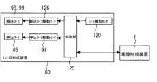
なお、図8は、上述したような動作をおこなうミシン目形成装置80を示すブロック図である。
図8に示すように、シート検知センサ120による検知結果に基づいて、制御部125によって搬送ローラ98、98を回転駆動する駆動モータ126が制御される。また、制御部125によって、所定のタイミングで、押圧ローラ85(押圧機構85~88)を幅方向に移動する移動機構の駆動モータ91が制御される。
FIG. 8 is a block diagram showing theperforation forming device 80 that operates as described above.
As shown in FIG. 8, based on the detection result of thesheet detection sensor 120, thecontrol unit 125 controls the drivingmotor 126 that drives the conveyingrollers 98, 98 to rotate. Further, thecontrol unit 125 controls thedrive motor 91 of the moving mechanism that moves the pressing roller 85 (pressingmechanisms 85 to 88) in the width direction at a predetermined timing.

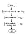
また、図9は、上述したミシン目形成時の制御をまとめとして示すフローチャートである。
まず、シート検知センサ120の検知結果に基づいて、シートPが所望のミシン目形成位置で搬送停止される(ステップS1)。そして、移動機構89~93によって押圧ローラ85(押圧機構85~88)の幅方向の移動が開始され、シートPにミシン目が形成される(ステップS2)。そして、シートPにミシン目が形成された後に、移動機構89~93による押圧ローラ85(押圧機構85~88)の移動が終了する(ステップS3)。
Further, FIG. 9 is a flow chart showing a summary of the control at the time of forming the perforations described above.
First, the sheet P is stopped at a desired perforation formation position based on the detection result of the sheet detection sensor 120 (step S1). Then, the pressing roller 85 (pressingmechanisms 85 and 88) starts to move in the width direction by the movingmechanisms 89 to 93, and perforations are formed on the sheet P (step S2). After the perforations are formed on the sheet P, the movement of the pressure roller 85 (thepressure mechanisms 85 to 88) by the movingmechanisms 89 to 93 is completed (step S3).

<変形例1>
図10は、変形例1としてのミシン目形成装置80(ミシン目形成装置主部81)の動作を示す図である。また、図11は、そのミシン目形成装置80を示すブロック図であって、本実施の形態における図8に対応する図である。また、図12は、そのミシン目形成装置80におけるミシン目形成時の制御を示すフローチャートであって、本実施の形態における図9に対応する図である。
図10に示すように、変形例1におけるミシン目形成装置80も、本実施の形態のものと同様に、非ミシン目形成時には制限部材83が上方に移動して搬送ガイド板として機能して、ミシン目形成時には制限部材83が下方に移動して押圧ローラ85の押圧方向の移動を制限する部材として機能する。
そして、変形例1では、本実施の形態とは異なり、ミシン目形成時における制限部材83の上下方向の位置を調整できるように構成されている。
変形例1では、これらの制限部材83の一連の上下動をカム110(カム機構)によっておこなっている。具体的に、カム機構は、制限部材83の上端部に下方から当接するカム110、カム110を回転駆動するモータ、制限部材83を下方に向けて付勢する付勢部材、などで構成されている。そして、モータの制御によってカム110の上死点(最大半径部)が制限部材83に当接しているとき、制限部材83は最上方に位置して搬送ガイド板として機能することになる。これに対して、その状態からからモータの制御によってカム110が図10(A)に示すように角度θ1だけ回転されると、制限部材83からミシン刃部82の刃先82aが所定量Z1だけ露呈した状態になり、カム110が図10(B)に示すように角度θ2(>θ1)だけ回転されると、制限部材83からミシン刃部82の刃先82aが所定量Z2(>Z1)だけ露呈した状態になる。
<Modification 1>
FIG. 10 is a diagram showing the operation of the perforation forming device 80 (perforation forming device main section 81) asModification 1. As shown in FIG. FIG. 11 is a block diagram showing theperforation forming device 80, corresponding to FIG. 8 in this embodiment. FIG. 12 is a flow chart showing control at the time of perforation formation in theperforation forming device 80, and is a diagram corresponding to FIG. 9 in the present embodiment.
As shown in FIG. 10, in theperforation forming device 80 inModification 1 as well as in the present embodiment, when the perforation is not formed, the restrictingmember 83 moves upward to function as a conveying guide plate. When the perforations are formed, the restrictingmember 83 moves downward and functions as a member restricting the movement of thepressing roller 85 in the pressing direction.
Further, in the modified example 1, unlike the present embodiment, the vertical position of the restrictingmember 83 can be adjusted when the perforations are formed.
InModification 1, a series of vertical movements of these restrictingmembers 83 are performed by a cam 110 (cam mechanism). Specifically, the cam mechanism is composed of acam 110 that contacts the upper end of thelimit member 83 from below, a motor that rotationally drives thecam 110, a biasing member that biases thelimit member 83 downward, and the like. there is When the top dead center (maximum radius portion) of thecam 110 is in contact with the limitingmember 83 under the control of the motor, the limitingmember 83 is positioned at the uppermost position and functions as a conveying guide plate. On the other hand, from this state, when thecam 110 is rotated by the angle θ1 as shown in FIG. 10A under the control of the motor, thecutting edge 82a of the sewingmachine blade portion 82 is exposed by the predetermined amount Z1 from the limitingmember 83. When thecam 110 is rotated by an angle .theta.2 (>.theta.1) as shown in FIG. 10B, thecutting edge 82a of the sewingmachine blade portion 82 is exposed from the limitingmember 83 by a predetermined amount Z2 (>Z1). state.

ここで、変形例1において、制限部材83は、ミシン目を形成するシートPの厚さ(紙厚)が厚いときに、シートPの厚さが薄いときに比べて、押圧方向の正方向に移動するように制御される。
具体的に、ミシン目形成処理をおこなうシートPの厚さが所定値A以下であるときには、シートPに対して尖状刃をそれほど深く押し込まなくてもミシン目を形成することができるため、上述したカム110の回転角度はθ1に設定されてミシン目形成処理がおこなわれる(図10(A)の状態である)。これに対して、ミシン目形成処理をおこなうシートPの厚さが所定値Aを超えるときには、シートPに対して尖状刃をある程度深く押し込まなくてはミシン目を形成することができないため、上述したカム110の回転角度はθ2(>θ1)に設定されてミシン目形成処理がおこなわれる(図10(B)の状態である)。
このように、シートPの厚さに応じて制限部材83の上下方向の位置を調整して、シートPに対する尖状刃の押し込み深さを変化させることで、シートPの厚さに関わらず良好なミシン目を形成することができる。
なお、シートPの厚さは、ユーザーによって操作表示パネル40に入力されるシートPの情報に基づいて検知することもできるし、ミシン目形成装置主部81に達するまでの搬送経路に設置された紙厚センサによって検知することもできる。そして、図11を参照して、そのようにシートPの厚さを検知する検知手段の検知結果に基づいて、制御部125による制御によってカム110を駆動するモータ127が制御されることになる。
Here, in Modified Example 1, when the thickness of the sheet P on which the perforations are formed (paper thickness) is thick, the restrictingmember 83 moves in the positive direction of the pressing direction compared to when the thickness of the sheet P is thin. controlled to move.
Specifically, when the thickness of the sheet P to be subjected to the perforation forming process is equal to or less than the predetermined value A, the perforations can be formed without pressing the sharp blade so deeply into the sheet P. The rotation angle of thecam 110 is set to .theta.1, and the perforation forming process is performed (the state shown in FIG. 10A). On the other hand, when the thickness of the sheet P on which the perforation is to be formed exceeds the predetermined value A, the perforation cannot be formed unless the sharpened blade is pushed into the sheet P to a certain depth. Then, the rotation angle of thecam 110 is set to θ2 (>θ1) and the perforation forming process is performed (the state shown in FIG. 10B).
In this manner, by adjusting the vertical position of the restrictingmember 83 according to the thickness of the sheet P and changing the depth of pushing of the sharp blade into the sheet P, the sheet P can be satisfactorily controlled regardless of the thickness of the sheet P. perforations can be formed.
The thickness of the sheet P can be detected based on the information of the sheet P input by the user to theoperation display panel 40, or the thickness of the sheet P can be detected based on the information of the sheet P, which is installed on the conveying path until reaching the perforation forming devicemain section 81. It can also be detected by a paper thickness sensor. Then, referring to FIG. 11, themotor 127 for driving thecam 110 is controlled by thecontrol unit 125 based on the detection result of the detection means for detecting the thickness of the sheet P. FIG.

まとめとして、図12のフロー図を用いて、変形例1におけるミシン目形成時の制御を説明する。
まず、シート検知センサ120の検知結果に基づいて、シートPが所望のミシン目形成位置で搬送停止される(ステップS1)。
そして、そのシートPの厚さが所定値A以下であるかが判別される(ステップS11)。その結果、シートPの厚さが所定値A以下であると判別された場合にはカム110が角度θ1(図10(A)の回転角度)で回転されて(ステップS12)、シートPの厚さが所定値A以下でないと判別された場合にはカム110が角度θ2(図10(B)の回転角度)で回転される(ステップS13)。
そして、移動機構89~93によって押圧ローラ85(押圧機構85~88)の幅方向の移動が開始され、シートPにミシン目が形成される(ステップS2)。そして、シートPにミシン目が形成された後に、移動機構89~93による押圧ローラ85(押圧機構85~88)の移動が終了する(ステップS3)。最後に、カム110がホームポジション(制限部材83を搬送ガイド板として機能させる位置である。)に復帰される(ステップS14)。
変形例1のようにミシン目形成装置80を構成した場合であっても、本実施の形態のものと同様に、装置が大型化、高コスト化することなく、装置の機械的寿命が向上することになる。
As a summary, the control at the time of perforation formation inModification 1 will be described using the flowchart of FIG. 12 .
First, the sheet P is stopped at a desired perforation formation position based on the detection result of the sheet detection sensor 120 (step S1).
Then, it is determined whether the thickness of the sheet P is equal to or less than a predetermined value A (step S11). As a result, when it is determined that the thickness of the sheet P is equal to or less than the predetermined value A, thecam 110 is rotated at an angle θ1 (the rotation angle in FIG. 10A) (step S12) to is not equal to or less than the predetermined value A, thecam 110 is rotated at an angle .theta.2 (the rotation angle in FIG. 10B) (step S13).
Then, the pressing roller 85 (pressingmechanisms 85 and 88) starts to move in the width direction by the movingmechanisms 89 to 93, and perforations are formed on the sheet P (step S2). After the perforations are formed on the sheet P, the movement of the pressure roller 85 (thepressure mechanisms 85 to 88) by the movingmechanisms 89 to 93 is completed (step S3). Finally, thecam 110 is returned to the home position (the position where the restrictingmember 83 functions as a transport guide plate) (step S14).
Even when theperforation forming device 80 is configured as inModification 1, the mechanical life of the device is improved without increasing the size and cost of the device, as in the case of the present embodiment. It will be.

<変形例2>
図13は、変形例2としてのミシン目形成装置80の要部を示す図である。
図13に示すように、変形例1におけるミシン目形成装置80(ミシン目形成装置主部81)に設置される制限部材83は、本実施の形態のものとは異なり、上流側の板金83aと下流側の板金83bとが左右対称形になっていない。
詳しくは、下流側の板金83bは、その上端部が下流側に水平方向に広がるように曲げ加工が施されている。これに対して、上流側の板金83aは、その上端部が、上流側に水平方向に広がり、さらに上流側で下方に傾斜するように曲げ加工が施されている。
また、図13(A)に示すように、非ミシン目形成時であって、制限部材83が搬送ガイド板として機能するときに、上流側の板金83aの上端部が、下流側の板金83bの上端部に比べて、上方に突出するように構成されている。このような構成は、圧縮スプリング96(図6参照)によって上方に付勢される上流側板金83aの上方への移動を規制する第2ストッパ部と、圧縮スプリング96によって上方に付勢される下流側板金83bの上方への移動を規制する第2ストッパ部と、の上下方向の位置をずらすことによって達成している。
図13(A)に示すように、非ミシン目形成時であって、制限部材83が搬送ガイド板として機能するときには、上流側板金83aの上端部の形状と、上流側板金83aと下流側板金83bとの段差と、によってシートPが制限部材83に引っ掛かることなく、スムーズに案内されながら搬送されることになる。
また、図13(B)に示すように、ミシン目形成時であって、制限部材83が押圧ローラ85の押圧方向の移動を制限する部材として機能するときには、上流側板金83aと下流側板金83bとがそれぞれ押圧ローラ85の大径部85cに当接することになる。
変形例2のようにミシン目形成装置80を構成した場合であっても、本実施の形態のものと同様に、装置が大型化、高コスト化することなく、装置の機械的寿命が向上することになる。
<Modification 2>
FIG. 13 is a diagram showing a main part of aperforation forming device 80 as Modification 2. As shown in FIG.
As shown in FIG. 13, the restrictingmember 83 installed in the perforation forming device 80 (perforation forming device main portion 81) inModification 1 differs from that of the present embodiment in that the upstreamside metal plate 83a It is not symmetrical with thesheet metal 83b on the downstream side.
Specifically, thesheet metal 83b on the downstream side is subjected to a bending process so that the upper end portion of thesheet metal 83b extends horizontally toward the downstream side. On the other hand, the upper end portion of thesheet metal 83a on the upstream side is bent in such a manner that it spreads horizontally toward the upstream side and then slopes downward on the upstream side.
Further, as shown in FIG. 13(A), when the perforation is not formed and the restrictingmember 83 functions as a conveying guide plate, the upper end of theupstream sheet metal 83a is aligned with thedownstream sheet metal 83b. It is configured to protrude upward compared to the upper end. Such a configuration includes a second stopper portion that restricts the upward movement of the upstreamside metal plate 83a that is biased upward by the compression spring 96 (see FIG. 6), and a downstream stopper portion that is biased upward by thecompression spring 96. This is achieved by shifting the vertical position of the second stopper portion that restricts the upward movement of theside metal plate 83b.
As shown in FIG. 13A, when the perforations are not formed and the restrictingmember 83 functions as a conveying guide plate, the shape of the upper end of theupstream sheet metal 83a and theupstream sheet metal 83a and the downstream sheet metal The sheet P is smoothly guided and conveyed without being caught by the restrictingmember 83 due to the difference in level with thesheet 83b.
Further, as shown in FIG. 13B, when the perforations are formed and the restrictingmember 83 functions as a member restricting the movement of thepressing roller 85 in the pressing direction, theupstream sheet metal 83a and thedownstream sheet metal 83b are separated from each other. contact the large-diameter portion 85c of thepressing roller 85, respectively.
Even when theperforation forming device 80 is configured as in Modification 2, the mechanical life of the device is improved without increasing the size and cost of the device, as in the case of the present embodiment. It will be.

<変形例3>
図14(A)は、変形例3としてのミシン目形成装置80において往路時に押圧ローラ85とミシン刃部82との接触部にかかる力を示す力学的モデル図であって、図14(B)は、その復路時に押圧ローラ85とミシン刃部82との接触部にかかる力を示す力学的モデル図である。なお、図14において、ミシン刃部82において幅方向に連続的に形成された尖状刃の刃先82aは、簡単のため凸凹状に図示している。
変形例3におけるミシン目形成装置80も、本実施の形態のものと同様に、押圧ローラ85(押圧部材)が、所定方向(幅方向)に離れた位置に配置された支軸86aを中心に回動可能に支持されている。そして、変形例3においても、押圧ローラ85は、支軸86aの側から押圧ローラ85の側に移動する方向(図2、図14の左方から右方に向かう方向である。)を往路として、押圧ローラ85の側から支軸86aの側に移動する方向(図2、図14の右方から左方に向かう方向である。)を復路として、往復移動可能に構成されている。
そして、変形例3では、押圧ローラ85(押圧機構85~88)を往路のみを移動させることで1枚のシートPにミシン目を形成する「第1モード」と、押圧ローラ85(押圧機構85~88)を往路と復路とのいずれかを移動させることで1枚のシートPにミシン目を形成する「第2モード」と、押圧ローラ85(押圧機構85~88)を往路と復路とを往復移動させることで1枚のシートPにミシン目を形成する「第3モード」と、を切替可能に構成されている。そして、シートPの厚さ(紙厚)に応じて、それらの3つのモードのうち1つのモードを選択して、ミシン目形成処理をおこなうように制御している。
このような制御をおこなうのは、押圧ローラ85が往路を移動してシートPにミシン目を形成するときにミシン刃部82(刃先82a)がシートPに突き刺さる力F1と、押圧ローラ85が復路を移動してシートPにミシン目を形成するときにミシン刃部82(刃先82a)がシートPに突き刺さる力F3と、が異なるためである(F1>F3である。)。
<Modification 3>
FIG. 14(A) is a dynamic model diagram showing the force applied to the contact portion between thepressure roller 85 and theperforation blade portion 82 during the outward movement in theperforation forming device 80 as Modification 3, and FIG. 14(B). 4 is a dynamic model diagram showing the force applied to the contact portion between thepressing roller 85 and theperforating blade portion 82 during the return movement. In FIG. 14, thecutting edge 82a of the sharp blade formed continuously in the width direction of theperforating blade portion 82 is illustrated in an uneven shape for the sake of simplicity.
In theperforation forming device 80 according to Modification 3, as in the present embodiment, the pressing roller 85 (pressing member) is centered on asupport shaft 86a arranged at a position spaced apart in a predetermined direction (width direction). It is rotatably supported. Also in Modified Example 3, the pressingroller 85 moves in the direction of moving from thesupport shaft 86a side to thepressing roller 85 side (the direction from the left to the right in FIGS. 2 and 14). , from the side of thepressure roller 85 to the side of thesupport shaft 86a (the direction from the right to the left in FIGS. 2 and 14) as a return path.
In Modified Example 3, the pressing roller 85 (pressingmechanisms 85 to 88) is moved only in the outward path to form perforations on one sheet P in a “first mode”, and the pressing roller 85 (pressingmechanism 85 . It is configured to be switchable between a "third mode" in which perforations are formed on one sheet P by reciprocating. Then, one of the three modes is selected according to the thickness of the sheet P (paper thickness), and the perforation forming process is performed.
Such control is performed by force F1 with which the perforating blade portion 82 (blade edge 82a) pierces the sheet P when thepressure roller 85 moves in the outward path and forms perforations on the sheet P, and This is because the force F3 with which the perforation blade portion 82 (theblade edge 82a) sticks into the sheet P when the perforation is formed on the sheet P by moving the perforation is different (F1>F3).

図14(A)に示すように、押圧ローラ85が往路を移動するときの、支軸86a(押圧ローラ85を保持する第1保持部材86の回動中心である。)から押圧ローラ85と刃先82aとの接触位置までの水平方向(幅方向)の距離をbとして、支軸86aから押圧ローラ85と刃先82aとの接触位置までの垂直方向(幅方向に直交する方向)の距離をaとして、押圧ローラ85と刃先82aとが接触するときに水平方向にかかる力をF2として、押圧ローラ85と刃先82aとが接触するときに垂直方向にかかる力をF1としたときに、支軸86aのまわりのモーメントT1は、次式で求められる。
T1=F1・b-F2・a・・・・(式1)
この(式1)から、上述した垂直方向の力F1は、次式で求められる。
F1=(T1+F2・a)/b・・・・(式2)
これに対して、図14(B)に示すように、押圧ローラ85が復路を移動するときの、支軸86aから押圧ローラ85と刃先82aとの接触位置までの水平方向の距離をcとして、支軸86aから押圧ローラ85と刃先82aとの接触位置までの垂直方向の距離をdとして、押圧ローラ85と刃先82aとが接触するときに水平方向にかかる力をF4として、押圧ローラ85と刃先82aとが接触するときに垂直方向にかかる力をF3としたときに、支軸86aのまわりのモーメントT2は、次式で求められる。
T2=F3・c+F4・d・・・・(式3)
この(式3)から、上述した垂直方向の力F3は、次式で求められる。
F3=(T2-F4・d)/c・・・・(式4)
ここで、図14(A)と図14(B)との力学モデル図を比較すると、上述したモーメントT1、T2は、圧縮スプリング88(図3等参照)のスプリング圧であるため、T1=T2となる。また、上述した距離a、dは、a=dとなる。また、上述した距離b、cについては、往路時と復路時とでは押圧ローラ85が接触する刃先82aの位置が異なるため、厳密にはb>cとなるが、刃先82aは尖状であるため、その差は僅かであり、b≒cとみなすことができる。また、上述した水平方向の力F2、F4は、刃先82aと押圧ローラ85との摩擦力であるのでF2=F4となる。よって、上述した(式4)におけるF3は、次式で近似することができる。
F3≒(T1-F2・a)/b・・・・(式5)
したがって、(式2)と(式5)との比較から、押圧ローラ85が往路を移動してシートPにミシン目を形成するときにミシン刃部82(刃先82a)がシートPに突き刺さる力F1は、押圧ローラ85が復路を移動してシートPにミシン目を形成するときにミシン刃部82(刃先82a)がシートPに突き刺さる力F3に比べて、大きいことがわかる(F1>F3である。)。すなわち、押圧ローラ85が往路を移動するときの方が、押圧ローラ85が復路を移動するときに比べて、シートPにミシン目を形成しやすいことになる。
しかし、シートPによっては、厚さが薄くて、刃先82aがシートPに突き刺さる力Fがそれほど大きくなくても、充分にミシン目を形成できる場合がある。また、ミシン目形成時に、往路も復路も利用できたら、連続通紙時における生産性が格段に向上することになる。
As shown in FIG. 14(A), when thepressure roller 85 moves in the forward path, thepressure roller 85 and the cutting edge are separated from thesupport shaft 86a (which is the rotation center of the first holdingmember 86 that holds the pressure roller 85). Let b be the horizontal (width direction) distance to the contact position with 82a, and let a be the vertical (perpendicular to the width direction) distance from thesupport shaft 86a to the contact position between thepressing roller 85 and thecutting edge 82a. , F2 is the force applied in the horizontal direction when thepressure roller 85 and thecutting edge 82a contact each other, and F1 is the force applied in the vertical direction when thepressure roller 85 and thecutting edge 82a contact each other. The moment T1 around is obtained by the following equation.
T1=F1・b−F2・a (Formula 1)
From this (Equation 1), the force F1 in the vertical direction is obtained by the following equation.
F1=(T1+F2·a)/b (Formula 2)
On the other hand, as shown in FIG. 14B, the horizontal distance from thesupport shaft 86a to the contact position between thepressure roller 85 and thecutting edge 82a when thepressure roller 85 moves in the return path is c. Let d be the vertical distance from thesupport shaft 86a to the contact position between thepressure roller 85 and theblade edge 82a, and let F4 be the force applied in the horizontal direction when thepressure roller 85 and theblade edge 82a contact each other. The moment T2 about thesupport shaft 86a is obtained by the following equation, where F3 is the force applied in the vertical direction when thecontact 82a contacts thesupport shaft 86a.
T2=F3.c+F4.d (Formula 3)
From this (Equation 3), the force F3 in the vertical direction described above is obtained by the following equation.
F3=(T2-F4·d)/c (Formula 4)
Here, when comparing the dynamic model diagrams of FIGS. 14A and 14B, the moments T1 and T2 described above are spring pressures of the compression spring 88 (see FIG. 3, etc.), so T1=T2. becomes. Moreover, the above-described distances a and d are a=d. Regarding the above-mentioned distances b and c, the position of thecutting edge 82a with which thepressing roller 85 contacts differs between the forward movement and the returning movement, so strictly speaking, b>c. , the difference is small and can be regarded as b≈c. Further, since the horizontal forces F2 and F4 described above are frictional forces between thecutting edge 82a and thepressure roller 85, F2=F4. Therefore, F3 in (Formula 4) described above can be approximated by the following formula.
F3≈(T1-F2・a)/b (Formula 5)
Therefore, from a comparison of (Equation 2) and (Equation 5), when thepressure roller 85 moves in the outward path and forms perforations on the sheet P, the perforation blade portion 82 (theblade edge 82a) pierces the sheet P with a force F1 is larger than the force F3 with which the perforating blade portion 82 (theblade edge 82a) pierces the sheet P when thepressure roller 85 moves in the backward path and forms perforations on the sheet P (F1>F3). .). That is, it is easier to form perforations on the sheet P when thepressure roller 85 moves in the outward path than when thepressure roller 85 moves in the homeward path.
However, depending on the sheet P, it may be possible to sufficiently form perforations even if the sheet P is thin and the force F with which thecutting edge 82a pierces the sheet P is not so large. In addition, if both the forward and backward passes can be used when forming perforations, the productivity during continuous sheet feeding will be significantly improved.

変形例3では、これらのことを勘案して、シートPの厚さ(紙厚)に応じて、1枚のシートPに対して往路のみを利用してミシン目形成処理をおこなう「第1モード」と、1枚のシートPに対して往路を利用したり復路を利用したりしてミシン目形成処理をおこなう「第2モード」と、1枚のシートPに対して往路と復路との往復経路を利用してミシン目形成処理をおこなう「第3モード」と、を使い分けている。
詳しくは、シートPの厚さH1が薄いときには、刃先82aがシートPに突き刺さる力Fがそれほど大きくなくても良いため、生産性を重視して、往路でも復路でもミシン目形成処理をできるように「第2モード」が選択される。「第2モード」が選択された場合であって、連続通紙時には、先行するシートPに対して往路を用いてミシン目形成処理がされた後、後行のシートに対しては復路を用いてミシン目形成処理がされて、それ以降、往路を用いたミシン目形成処理と、復路を用いたミシン目形成処理と、が交互に繰り返されることになる。
これに対して、シートPの厚さH2(>H1)が中程度のときには、刃先82aがシートPに突き刺さる力Fがある程度大きくなくてはならないため、復路を用いてのミシン目形成処理はおこなわずに、往路を用いてのミシン目形成処理のみをおこなう「第1モード」が選択される。「第1モード」が選択された場合には、連続通紙時であっても、1枚のシートPに対して往路を用いてのミシン目形成処理が終了するたびに、押圧機構85~88がホームポジション(図2の左方の退避台94である。)に戻されることになる。
さらに、シートPの厚さH3(>H2>H1)が厚いときには、刃先82aがシートPに突き刺さる力Fがとても大きくなくてはならないため、往復経路を用いてのミシン目形成処理をおこなう「第3モード」が選択される。「第3モード」が選択された場合には、1枚のシートPに対して往路を用いてのミシン目形成処理をおこなった後に、復路を用いたミシン目形成処理が重ねておこなわれることになる。
なお、シートPの厚さを検知する検知手段としては、先に図11等で説明した検知手段128を用いることができる。
変形例3のようにミシン目形成装置80を構成した場合であっても、本実施の形態のものと同様に、装置が大型化、高コスト化することなく、装置の機械的寿命が向上することになる。
In the modified example 3, taking these things into account, according to the thickness of the sheet P (paper thickness), perforation forming processing is performed on one sheet P using only the outward path ("first mode , a "second mode" in which the perforation forming process is performed on one sheet P by using the forward pass and the return pass, and a reciprocation between the forward pass and the return pass on one sheet P. A "third mode" that performs perforation formation processing using the path is used properly.
Specifically, when the thickness H1 of the sheet P is thin, the force F with which thecutting edge 82a pierces the sheet P does not have to be so large. "Second Mode" is selected. When the "second mode" is selected and continuous sheet feeding is performed, the preceding sheet P is subjected to perforation formation processing using the forward pass, and then the succeeding sheet is subjected to the return pass. After that, the perforation forming process using the forward pass and the perforation forming process using the return pass are alternately repeated.
On the other hand, when the thickness H2 (>H1) of the sheet P is medium, the force F with which thecutting edge 82a pierces the sheet P must be large to some extent. Instead, the "first mode" is selected in which only the perforation forming process is performed using the forward pass. When the "first mode" is selected, thepressing mechanisms 85 to 88 are pressed each time the perforation forming process for one sheet P using the forward pass is completed even during continuous sheet feeding. is returned to the home position (theevacuation platform 94 on the left in FIG. 2).
Furthermore, when the thickness H3 (>H2>H1) of the sheet P is thick, the force F with which thecutting edge 82a pierces the sheet P must be very large. 3 mode” is selected. When the "third mode" is selected, the perforation forming process using the forward pass is performed on one sheet P, and then the perforation forming process using the return pass is superimposed. Become.
As a detection means for detecting the thickness of the sheet P, the detection means 128 described above with reference to FIG. 11 and the like can be used.
Even if theperforation forming device 80 is configured as in Modification 3, the mechanical life of the device is improved without increasing the size and cost of the device, as in the case of the present embodiment. It will be.

<変形例4>
図15は、変形例4としてのミシン目形成装置80の動作を示す図である。また、図16は、それとは別形態のミシン目形成装置80の動作を示す図である。
変形例4におけるミシン目形成装置80は、移動機構89~93によって移動する押圧ローラ85(押圧機構85~88)の移動経路が、本実施の形態のものと相違する。
図15(A)~(E)に示すように、変形例4では、押圧ローラ85(押圧部材)をシートPに対して幅方向(所定方向)の中央部で最初に押圧させて、その後に押圧状態の押圧ローラ85を幅方向一端側(所定方向の一端側であって、図15の右方である。)に移動させて、その後に押圧状態の押圧ローラ85を幅方向他端側(所定方向の他端側であって、図15の左方である。)に移動させている。
詳しくは、まず、図15(A)に示すように、シートPがミシン刃部82の上方に搬送されたとき、押圧ローラ85(押圧機構85~88)は、幅方向の中央部の上方に退避している。
そして、図15(B)に示すように、搬送停止状態のシートPの幅方向中央部に押圧ローラ85が圧接するように、ガイドレール89を上下動する接離機構(例えば、移動機構89~93を全体的に上下動させるカム機構である。)が動作する。これにより、シートPの幅方向中央部に最初にミシン目が形成される。
その後、図15(C)に示すように、移動機構89~93によって、押圧ローラ85は、シートPを介して制限部材83に当接した状態のまま、図15の中央から右方に移動する。これにより、シートPの幅方向中央部から幅方向一端側にかけてミシン目が形成される。
その後、図15(D)に示すように、移動機構89~93によって、押圧ローラ85は、シートPを介して制限部材83に当接した状態のまま、図15の右方から左方に移動する。これにより、シートPの幅方向全域にわたってミシン目が形成される。
その後、図15(E)に示すように、押圧ローラ85(押圧機構85~88)は、接離機構によって上方の退避位置に移動した後に、幅方向中央部のホームポジションに移動する。
ここで、図16に示すミシン目形成装置80は、押圧ローラ85を上下動させる接離機構の構成が、図15に示すものと異なる。具体的に、図16(A)~(E)に示すように、モータ(接離機構)の動作によって、第2保持部材87に保持された状態で押圧ローラ85(第1保持部材86)が支軸86aを中心に角度θの範囲で正逆方向に回動可能に構成されている。そして、図16(A)、(E)に示すように、押圧ローラ85(第1保持部材86)が支軸86aを中心に角度θだけ反時計方向に回動しているときには、押圧ローラ85がシートPや制限部材83から上方に退避した状態になる。これに対して、図16(B)~(D)に示すように、押圧ローラ85(第1保持部材86)が支軸86aを中心に角度θだけ時計方向に回動しているときには、押圧ローラ85がシートPを介して制限部材83に当接した状態になる。このように構成することで、ガイドレール89を上下動させなくてすむため、接離機構の構成が簡易になる。そして、図16(B)~(D)に示すように、図16に示すミシン目形成装置80も、図15に示すものとほぼ同様の移動経路で、押圧ローラ85(押圧機構85~88)が幅方向に移動することになる。
変形例4のようにミシン目形成装置80を構成した場合であっても、本実施の形態のものと同様に、装置が大型化、高コスト化することなく、装置の機械的寿命が向上することになる。
特に、変形例4では、押圧ローラ85をシートPに対して幅方向中央部で最初に押圧させているため、シートPの幅方向中央部がミシン刃部82に突き刺さった状態で固定されて、その後に押圧ローラ85が幅方向に移動しても、シートPが引きずられるように移動する不具合が生じにくい。そのため、シートPにきれいなミシン目を形成することができる。
<Modification 4>
15A and 15B are diagrams showing the operation of theperforation forming device 80 asModification 4. FIG. 16A and 16B are diagrams showing the operation of aperforation forming device 80 of another form.
Perforation forming device 80 inModification 4 differs from that of the present embodiment in the movement path of pressing roller 85 (pressing mechanisms 85-88) moved by moving mechanisms 89-93.
As shown in FIGS. 15A to 15E, in Modified Example 4, the pressing roller 85 (pressing member) is first pressed against the sheet P at the central portion in the width direction (predetermined direction), and then Thepressure roller 85 in the pressed state is moved to one end in the width direction (one end in a predetermined direction, which is the right side in FIG. 15), and then thepressure roller 85 in the pressed state is moved to the other end in the width direction ( 15, which is the other end in the predetermined direction).
More specifically, first, as shown in FIG. 15A, when the sheet P is conveyed above theperforating blade portion 82, the pressing roller 85 (pressingmechanisms 85 to 88) moves above the central portion in the width direction. are evacuating.
Then, as shown in FIG. 15B, a contact/separation mechanism (for example, movingmechanisms 89 to 89) moves theguide rail 89 up and down so that thepressing roller 85 is pressed against the center of the sheet P in the width direction while the conveyance is stopped. 93 is a cam mechanism that moves up and down as a whole.) operates. As a result, perforations are first formed in the central portion of the sheet P in the width direction.
Thereafter, as shown in FIG. 15C, the pressingroller 85 is moved rightward from the center of FIG. . As a result, a perforation is formed from the central portion in the width direction of the sheet P to the one end side in the width direction.
Thereafter, as shown in FIG. 15(D), thepressure roller 85 is moved from the right to the left in FIG. do. As a result, perforations are formed across the width of the sheet P. As shown in FIG.
After that, as shown in FIG. 15(E), the pressing roller 85 (pressingmechanisms 85 to 88) moves to the home position at the center in the width direction after being moved to the upper retracted position by the contact/separation mechanism.
Here, theperforation forming device 80 shown in FIG. 16 differs from that shown in FIG. 15 in the configuration of the contact/separation mechanism for moving thepressure roller 85 up and down. Specifically, as shown in FIGS. 16A to 16E, the pressure roller 85 (first holding member 86) is moved while being held by the second holdingmember 87 by the operation of the motor (contact/separation mechanism). It is configured to be rotatable in forward and reverse directions within the range of angle θ about thesupport shaft 86a. As shown in FIGS. 16A and 16E, when the pressure roller 85 (first holding member 86) rotates counterclockwise about thesupport shaft 86a by an angle θ, thepressure roller 85 is retracted upward from the sheet P and the restrictingmember 83 . On the other hand, as shown in FIGS. 16B to 16D, when the pressure roller 85 (first holding member 86) rotates clockwise about thesupport shaft 86a by an angle θ, the pressure Theroller 85 comes into contact with the restrictingmember 83 with the sheet P therebetween. With this configuration, theguide rail 89 does not need to be moved up and down, so the configuration of the contact/separation mechanism is simplified. As shown in FIGS. 16B to 16D, theperforation forming device 80 shown in FIG. will move in the width direction.
Even when theperforation forming device 80 is configured as inModification 4, the mechanical life of the device is improved without increasing the size and cost of the device, as in the case of the present embodiment. It will be.
In particular, inModification 4, since thepressing roller 85 is pressed against the sheet P at the central portion in the width direction first, the central portion in the width direction of the sheet P is stuck in theperforating blade portion 82 and fixed. Even if thepressing roller 85 moves in the width direction thereafter, the problem of the sheet P being dragged is less likely to occur. Therefore, clean perforations can be formed on the sheet P.

<変形例5>
図17は、変形例5としてのミシン目形成装置80において押圧ローラ85の移動が制限部材83によって制限された状態を示す正面図であって、本実施の形態における図4に対応する図である。
図17に示すように、変形例5におけるミシン目形成装置80における押圧ローラ85には、小径部85b(溝部)が設けられていない。
そのため、ミシン目形成時において、押圧ローラ85がシートPを介して制限部材83に当接するときに、押圧ローラ85の表面にシートPを貫通したミシン刃部82の刃先82aが突き刺さる可能性がある。しかし、押圧ローラ85の押圧方向の移動(位置)が制限部材83によって制限されるため、そのような制限がない場合に比べて、ミシン刃部82の刃先82aが押圧ローラ85に突き刺さる深さが制限されて、ミシン刃部82や押圧ローラ85の耐久性を向上させることができる。
したがって、変形例5のようにミシン目形成装置80を構成した場合であっても、本実施の形態のものと同様に、装置が大型化、高コスト化することなく、装置の機械的寿命が向上することになる。
<Modification 5>
FIG. 17 is a front view showing a state in which the movement of thepressure roller 85 is restricted by therestriction member 83 in theperforation forming device 80 as Modification 5, and corresponds to FIG. 4 in the present embodiment. .
As shown in FIG. 17, thepress roller 85 in theperforation forming device 80 according to Modification 5 is not provided with the small-diameter portion 85b (groove portion).
Therefore, when thepressing roller 85 contacts the restrictingmember 83 through the sheet P during perforation formation, there is a possibility that thecutting edge 82a of theperforating blade portion 82 penetrating the sheet P may pierce the surface of thepressing roller 85. . However, since the movement (position) of thepressing roller 85 in the pressing direction is restricted by the restrictingmember 83, the depth at which thecutting edge 82a of theperforating blade portion 82 penetrates thepressing roller 85 is greater than in the case where there is no such restriction. As a result, the durability of theperforating blade portion 82 and thepressing roller 85 can be improved.
Therefore, even if theperforation forming device 80 is configured as in the modified example 5, the mechanical life of the device can be extended without increasing the size and cost of the device, as in the case of the present embodiment. will improve.

<変形例6>
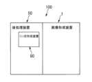
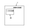
図18は、変形例6としての画像形成システム100を示す概略図である。また、図19は、別形態としての画像形成装置1を示す概略図である。
図18に示すように、変形例6における画像形成システム100は、画像形成装置1と後処理装置50とで構成されていて、後処理装置50にミシン目形成装置80が内蔵されている点が、画像形成システム100においてミシン目形成装置80が画像形成装置1と後処理装置50とは別に設けられている本実施の形態のものと相違する。
また、図19に示す画像形成装置1は、その内部にミシン目形成装置80が設けられている。
変形例6のようにミシン目形成装置80を設置した場合であっても、本実施の形態のものと同様に、装置が大型化、高コスト化することなく、装置の機械的寿命が向上することになる。
<Modification 6>
FIG. 18 is a schematic diagram showing animage forming system 100 as Modified Example 6. As shown in FIG. Also, FIG. 19 is a schematic diagram showing animage forming apparatus 1 as another form.
As shown in FIG. 18, theimage forming system 100 inModification 6 includes animage forming apparatus 1 and apost-processing device 50, and theperforation forming device 80 is incorporated in thepost-processing device 50. 2, theimage forming system 100 differs from the present embodiment in which theperforation forming device 80 is provided separately from theimage forming device 1 and thepost-processing device 50 .
Further, theimage forming apparatus 1 shown in FIG. 19 is provided with aperforation forming device 80 therein.
Even when theperforation forming device 80 is installed as inModification 6, the mechanical life of the device is improved without increasing the size and cost of the device, as in the case of the present embodiment. It will be.

以上説明したように、本実施の形態におけるミシン目形成装置80は、所定方向に複数の尖状刃が並設されたミシン刃部82と、ミシン刃部82との間にシートPを挟んだ状態でシートPをミシン刃部82に向けて押圧しながら所定方向に移動する押圧ローラ85(押圧部材)と、ミシン刃部82に対する押圧ローラ85の押圧方向の相対的な移動を制限する制限部材83と、が設けられている。
これにより、ミシン目形成装置80が大型化、高コスト化することなく、ミシン目形成装置80の機械的寿命が向上することになる。
As described above, theperforation forming device 80 according to the present embodiment has the sheet P sandwiched between theperforation blade portion 82 having a plurality of pointed blades arranged side by side in a predetermined direction and theperforation blade portion 82. a pressing roller 85 (pressing member) that moves in a predetermined direction while pressing the sheet P toward theperforating blade portion 82 in the state, and a restricting member that restricts the relative movement of thepressing roller 85 with respect to theperforating blade portion 82 in the pressing direction. 83 and are provided.
As a result, the mechanical life of theperforation forming device 80 is improved without increasing the size and cost of theperforation forming device 80 .

なお、本実施の形態では、電子写真方式の画像形成装置1に接続されるミシン目形成装置80に対して本発明を適用したが、本発明の適用はこれに限定されることなく、その他の方式の画像形成装置(例えば、インクジェット方式の画像形成装置や、孔版印刷装置などである。)に接続されるミシン目形成装置に対しても当然に本発明を適用することができる。
そして、そのような場合であっても、本実施の形態のものと同様の効果を得ることができる。
In the present embodiment, the present invention is applied to theperforation forming device 80 connected to the electrophotographicimage forming apparatus 1, but the application of the present invention is not limited to this. The present invention can of course also be applied to a perforation forming apparatus connected to an image forming apparatus (for example, an inkjet image forming apparatus, a stencil printing apparatus, etc.).
Even in such a case, the same effects as those of the present embodiment can be obtained.

また、本実施の形態では、後処理装置50における後処理機構として、ステープラ75、パンチ処理部70、ソート処理部58、シート揃え部60を設けたが、後処理機構はこれらのものに限定されることなく、折り処理や中折り処理など別の処理をもおこなうように後処理機構を構成することもできるし、上述した複数の処理部のうち別の組み合わせからなるように後処理機構を構成することもできる。
そして、そのような場合であっても、本実施の形態のものと同様の効果を得ることができる。
In the present embodiment, thestapler 75, thepunch processing section 70, thesort processing section 58, and thesheet aligning section 60 are provided as post-processing mechanisms in thepost-processing device 50, but the post-processing mechanisms are limited to these. The post-processing mechanism can also be configured to perform other processing such as folding processing and center-folding processing without having to do so, and the post-processing mechanism can be configured to include different combinations of the plurality of processing units described above. You can also
Even in such a case, the same effects as those of the present embodiment can be obtained.

なお、本発明が本実施の形態に限定されず、本発明の技術思想の範囲内において、本実施の形態の中で示唆した以外にも、本実施の形態は適宜変更され得ることは明らかである。また、前記構成部材の数、位置、形状等は本実施の形態に限定されず、本発明を実施する上で好適な数、位置、形状等にすることができる。 It should be noted that the present invention is not limited to the present embodiment, and it is obvious that the present embodiment can be appropriately modified within the scope of the technical idea of the present invention other than suggested in the present embodiment. be. Moreover, the number, position, shape, etc. of the constituent members are not limited to those of the present embodiment, and the number, position, shape, etc. can be set to be suitable for carrying out the present invention.

なお、本願明細書等において、「シート」とは、通常の用紙に限定されることなく、シート状の媒体のすべて、例えば、コート紙、ラベル紙、OHPシート、金属シート、フィルム、プリプレグ、布、織物、等も含むものと定義する。
また、本願明細書等において、「ミシン目」とは、対象体に形成される連続的な穴であるものと定義する。
In this specification and the like, "sheet" is not limited to ordinary paper, but includes all sheet-like media such as coated paper, label paper, OHP sheet, metal sheet, film, prepreg, and cloth. , textiles, etc.
Further, in the specification of the present application and the like, "perforation" is defined as a continuous hole formed in the object.

1 画像形成装置、
50 後処理装置、
80 ミシン目形成装置(シート部分切断装置)、
81 ミシン目形成装置主部、
82 ミシン刃部、
82a 刃先(尖状刃の刃先)、
83 制限部材(位置決め部材)、
85 押圧ローラ(押圧部材)、
85a 軸部、
85b 小径部、
85c 大径部、
86 第1保持部材、
86a 支軸、
87 第2保持部材、
100 画像形成システム、
P シート。
1 image forming apparatus,
50 post-processing device,
80 perforation forming device (sheet partial cutting device),
81 main part of perforation forming device,
82 sewing machine blade,
82a cutting edge (cutting edge of pointed blade),
83 limiting member (positioning member),
85 pressing roller (pressing member),
85a shaft,
85b small diameter portion,
85c large diameter portion,
86 first holding member,
86a spindle,
87 second holding member,
100 imaging system;
P sheet.

特許第2961425号公報Japanese Patent No. 2961425

Claims (13)

Translated fromJapanese
シートにミシン目を形成するミシン目形成装置であって、
所定方向に複数の尖状刃が並設されたミシン刃部と、
前記ミシン刃部との間にシートを挟んだ状態で、当該シートを前記ミシン刃部に向けて押圧しながら前記所定方向に移動する押圧部材と、
前記ミシン刃部に対する前記押圧部材の押圧方向の相対的な移動を制限する制限部材と、
を備え、
前記押圧部材は、
前記所定方向に離れた位置に配置された支軸を中心に回動可能に支持されて、
前記支軸の側から前記押圧部材の側に移動する方向を往路として、前記押圧部材の側から前記支軸の側に移動する方向を復路として、往復移動可能に構成され、
前記押圧部材を前記往路と前記復路とのいずれか一方に移動させることで1枚のシートにミシン目を形成するか、前記押圧部材を前記往路と前記復路とを往復移動させることで1枚のシートにミシン目を形成するか、を切替可能に構成されたことを特徴とするミシン目形成装置。
A perforation forming device for forming perforations on a sheet,
a sewing machine blade portion in which a plurality of sharp blades are arranged in a predetermined direction;
a pressing member that moves in the predetermined direction while pressing the sheet toward the perforating blade while sandwiching the sheet between itself and the perforating blade;
a restricting member that restricts relative movement of the pressing member in the pressing direction with respect to the sewing machine blade;
with
The pressing member is
rotatably supported around a support shaft arranged at a position spaced apart in the predetermined direction,
It is configured to be able to reciprocate in a direction of movement from the support shaft side to the pressing member side as an outward path and a direction of movement from the pressing member side to the support shaft side as a return path,
Perforations are formed on one sheet by moving the pressing member in either one of the outward path and the homeward path, or one sheet is formed by reciprocating the pressing member between the outward path and the homeward path. A perforation forming device characterizedby being configured to be able to switch between forming perforations on a sheet .
前記押圧部材は、前記押圧部材を前記往路と前記復路とのいずれか一方に移動させることで1枚のシートにミシン目を形成するか、前記押圧部材を前記往路と前記復路とを往復移動させることで1枚のシートにミシン目を形成するか、を前記シートの厚さに応じて切替可能に構成されたことを特徴とする請求項1に記載のミシン目形成装置。The pressing member forms perforations in one sheet by moving the pressing member in one of the forward path and the returning path, or reciprocates the pressing member between the outward path and the return path. 2. The perforation forming device according to claim 1, wherein the perforation forming apparatus according to claim 1 is configured so as to be capable of switching whether to form perforations on one sheet according to the thickness of said sheet.前記押圧部材は、前記押圧部材を前記往路を移動させることで1枚のシートにミシン目を形成するか、前記押圧部材を前記復路を移動させることで1枚のシートにミシン目を形成するか、を前記シートの厚さに応じて切替可能に構成されたことを特徴とする請求項1又は請求項2に記載のミシン目形成装置。The pressing member forms perforations on one sheet by moving the pressing member on the outward path, or forms perforations on one sheet by moving the pressing member on the return path. 3. The perforation forming apparatus according to claim 1, wherein the perforation forming apparatus is configured to be switchable according to the thickness of the sheet.シートにミシン目を形成するミシン目形成装置であって、A perforation forming device for forming perforations on a sheet,
所定方向に複数の尖状刃が並設されたミシン刃部と、a sewing machine blade portion in which a plurality of sharp blades are arranged in a predetermined direction;
前記ミシン刃部との間にシートを挟んだ状態で、当該シートを前記ミシン刃部に向けて押圧しながら前記所定方向に移動する押圧部材と、a pressing member that moves in the predetermined direction while pressing the sheet toward the perforating blade while sandwiching the sheet between itself and the perforating blade;
前記ミシン刃部に対する前記押圧部材の押圧方向の相対的な移動を制限する制限部材と、a restricting member that restricts relative movement of the pressing member in the pressing direction with respect to the sewing machine blade;
を備え、with
前記押圧部材をシートに対して前記所定方向の中央部で最初に押圧させて、その後に押圧状態の前記押圧部材を前記所定方向の一端側に移動させて、その後に押圧状態の前記押圧部材を前記所定方向の他端側に移動させることを特徴とするミシン目形成装置。The pressing member is first pressed against the sheet at the central portion in the predetermined direction, then the pressing member in the pressing state is moved to one end side in the predetermined direction, and then the pressing member in the pressing state is moved. A perforation forming device, wherein the perforation forming device is moved to the other end side in the predetermined direction.
前記押圧部材は、前記所定方向に沿うように回転しながら前記所定方向に移動する押圧ローラであって、The pressing member is a pressing roller that moves in the predetermined direction while rotating along the predetermined direction,
前記押圧ローラは、前記制限部材による制限によって前記複数の尖状刃に接しないように対向する小径部と、前記小径部を間に挟むように形成されて前記押圧部材による押圧によって前記複数の尖状刃に接することなく前記シートに接する一対の大径部と、を具備したことを特徴とする請求項1~請求項4のいずれかに記載のミシン目形成装置。The pressing roller has a small-diameter portion opposed to the plurality of pointed blades so as not to come into contact with them due to the restriction by the restricting member, and a small-diameter portion sandwiching the small-diameter portion. The perforation forming device according to any one of claims 1 to 4, further comprising a pair of large-diameter portions that contact the sheet without contacting the blade.
前記制限部材は、前記押圧方向に移動する前記押圧部材に当接することにより、押圧時における前記ミシン刃部に対する前記押圧部材の前記押圧方向の位置を定めることを特徴とする請求項1~請求項5のいずれかに記載のミシン目形成装置。The restricting member abuts against the pressing member moving in the pressing direction, thereby determining the position of the pressing member in the pressing direction with respect to the sewing machine blade portion during pressing. 6. The perforation forming device according to any one of 5.前記押圧部材は、支軸を中心に回動可能に支持されて、The pressing member is rotatably supported around a support shaft,
前記複数の尖状刃の刃先から前記支軸までの前記押圧方向の距離をMとして、前記複数の尖状刃の刃先から前記押圧部材の重心までの前記押圧方向の距離をNとしたときに、When the distance in the pressing direction from the cutting edge of the plurality of sharpened blades to the support shaft is M, and the distance in the pressing direction from the cutting edge of the plurality of sharpened blades to the center of gravity of the pressing member is N, ,
M≧NM≧N
なる関係が成立することを特徴とする請求項1~請求項6のいずれかに記載のミシン目形成装置。The perforation forming device according to any one of claims 1 to 6, characterized in that a relationship is established.
前記制限部材は、前記押圧方向に対して正逆方向に移動可能に構成されたことを特徴とする請求項1~請求項7のいずれかに記載のミシン目形成装置。The perforation forming apparatus according to any one of claims 1 to 7, wherein the restricting member is configured to be movable in forward and reverse directions with respect to the pressing direction.シートにミシン目を形成することなく当該シートを搬送するときには、当該シートが前記複数の尖状刃に接しないように前記制限部材が前記押圧方向の逆方向に移動して、前記制限部材が当該シートの搬送を案内して、When conveying the sheet without forming perforations on the sheet, the restricting member moves in a direction opposite to the pressing direction so that the sheet does not come into contact with the plurality of pointed blades. Guide the sheet transport,
シートにミシン目を形成するときには、搬送停止された状態の当該シートが前記複数の尖状刃に接するように前記制限部材が前記押圧方向の正方向に移動して、前記制限部材によって制限された状態で前記押圧部材が当該シートを押圧することを特徴とする請求項8に記載のミシン目形成装置。When perforations are formed on the sheet, the limiting member moves in the positive direction of the pressing direction so that the sheet in a state where conveyance is stopped comes into contact with the plurality of pointed blades, and is limited by the limiting member. 9. The perforation forming apparatus according to claim 8, wherein the pressing member presses the sheet in a state.
前記制限部材は、ミシン目を形成するシートの厚さが厚いときに、シートの厚さが薄いときに比べて、前記押圧方向の正方向に移動することを特徴とする請求項8又は請求項9に記載のミシン目形成装置。8. The restricting member moves in the positive direction of the pressing direction when the sheet forming the perforations is thick, compared to when the sheet is thin. 10. The perforation forming device according to 9.画像形成装置から排出されたシートに後処理を施す後処理装置であって、A post-processing device that performs post-processing on a sheet discharged from an image forming apparatus,
請求項1~請求項10のいずれかに記載のミシン目形成装置を備えたことを特徴とする後処理装置。A post-processing device comprising the perforation forming device according to any one of claims 1 to 10.
請求項1~請求項10のいずれかに記載のミシン目形成装置を備えたことを特徴とする画像形成装置。An image forming apparatus comprising the perforation forming apparatus according to any one of claims 1 to 10.画像形成装置を備えた画像形成システムであって、An image forming system comprising an image forming apparatus,
請求項1~請求項10のいずれかに記載のミシン目形成装置を備えたことを特徴とする画像形成システム。An image forming system comprising the perforation forming device according to any one of claims 1 to 10.
JP2018236067A2018-12-182018-12-18 Perforation forming device, post-processing device, image forming device, and image forming systemActiveJP7223251B2 (en)

Priority Applications (1)

Application NumberPriority DateFiling DateTitle
JP2018236067AJP7223251B2 (en)2018-12-182018-12-18 Perforation forming device, post-processing device, image forming device, and image forming system

Applications Claiming Priority (1)

Application NumberPriority DateFiling DateTitle
JP2018236067AJP7223251B2 (en)2018-12-182018-12-18 Perforation forming device, post-processing device, image forming device, and image forming system

Publications (2)

Publication NumberPublication Date
JP2020097082A JP2020097082A (en)2020-06-25
JP7223251B2true JP7223251B2 (en)2023-02-16

Family

ID=71105592

Family Applications (1)

Application NumberTitlePriority DateFiling Date
JP2018236067AActiveJP7223251B2 (en)2018-12-182018-12-18 Perforation forming device, post-processing device, image forming device, and image forming system

Country Status (1)

CountryLink
JP (1)JP7223251B2 (en)

Citations (1)

* Cited by examiner, † Cited by third party
Publication numberPriority datePublication dateAssigneeTitle
JP2961425B2 (en)1988-08-261999-10-12株式会社小森コーポレーション Horizontal perforation processing equipment for rotary printing press

Family Cites Families (3)

* Cited by examiner, † Cited by third party
Publication numberPriority datePublication dateAssigneeTitle
US1542097A (en)*1921-06-061925-06-16Albert E RipleyPerforating attachment
JPS6270170A (en)*1985-09-191987-03-31Fuji Photo Film Co LtdPhotographic paper handling device
BE1004500A3 (en)*1990-06-211992-12-01Web Converting Equipment NvDevice for intermittent running a treatment of a strip.

Patent Citations (1)

* Cited by examiner, † Cited by third party
Publication numberPriority datePublication dateAssigneeTitle
JP2961425B2 (en)1988-08-261999-10-12株式会社小森コーポレーション Horizontal perforation processing equipment for rotary printing press

Also Published As

Publication numberPublication date
JP2020097082A (en)2020-06-25

Similar Documents

PublicationPublication DateTitle
JP6829813B2 (en) Binding device and image forming device
US10421307B2 (en)Sheet binding system, image forming apparatus with sheet binding system, and method of binding sheet bundle
US8201815B2 (en)Sheet folding apparatus, image forming apparatus using the same, and sheet folding method
US8931773B2 (en)Sheet folding device having inclined stacking surface
JP5730260B2 (en) Punching device, post-processing device and image forming device
US8876107B2 (en)Sheet stacking device, image forming system, and sheet stacking method
EP1650145B1 (en)Paper post-processing method for punching paper and apparatus therefore
JP3937779B2 (en) Post-processing apparatus and image forming system
JP5566509B2 (en) Sheet processing apparatus and image forming apparatus
EP3034444B1 (en)Sheet post-processing device and corresponding sheet post-processing method
JP7223251B2 (en) Perforation forming device, post-processing device, image forming device, and image forming system
KR20020058317A (en)Paper sorting device for image forming apparatus
JP4294402B2 (en) Sheet cutting apparatus and image forming apparatus provided with the apparatus
JP2012218900A (en)Paper processing device and image forming device
JP6274521B2 (en) Paper processing apparatus and image forming apparatus
JP6638047B2 (en) Sheet processing apparatus and image forming system using the same
JP2022020359A (en) Post-processing equipment and image formation system
JP3931544B2 (en) Post-processing equipment
JP6332512B2 (en) Sheet processing apparatus and image forming apparatus
JP2004284749A (en)Sheet handling device
JP6213766B2 (en) Conveying apparatus, post-processing apparatus, and image forming apparatus
JP7307399B2 (en) SHEET PROCESSING APPARATUS AND IMAGE FORMING SYSTEM
JP6459036B2 (en) Paper folding processing apparatus and image forming apparatus
JP2019116338A (en)Sheet processing apparatus and image formation system having the same
JP2007001757A (en) Sheet medium punching mechanism, sheet medium punching apparatus, post-processing apparatus, image forming apparatus

Legal Events

DateCodeTitleDescription
A621Written request for application examination

Free format text:JAPANESE INTERMEDIATE CODE: A621

Effective date:20210915

A977Report on retrieval

Free format text:JAPANESE INTERMEDIATE CODE: A971007

Effective date:20220708

A131Notification of reasons for refusal

Free format text:JAPANESE INTERMEDIATE CODE: A131

Effective date:20220803

A521Request for written amendment filed

Free format text:JAPANESE INTERMEDIATE CODE: A523

Effective date:20221003

TRDDDecision of grant or rejection written
A01Written decision to grant a patent or to grant a registration (utility model)

Free format text:JAPANESE INTERMEDIATE CODE: A01

Effective date:20230105

A61First payment of annual fees (during grant procedure)

Free format text:JAPANESE INTERMEDIATE CODE: A61

Effective date:20230118

R151Written notification of patent or utility model registration

Ref document number:7223251

Country of ref document:JP

Free format text:JAPANESE INTERMEDIATE CODE: R151


[8]ページ先頭

©2009-2025 Movatter.jp