JP7221228B2 - A motorized circular stapler with a reciprocating drive member that provides independent tissue stapling and cutting - Google Patents
A motorized circular stapler with a reciprocating drive member that provides independent tissue stapling and cuttingDownload PDFInfo
- Publication number
- JP7221228B2 JP7221228B2JP2019571445AJP2019571445AJP7221228B2JP 7221228 B2JP7221228 B2JP 7221228B2JP 2019571445 AJP2019571445 AJP 2019571445AJP 2019571445 AJP2019571445 AJP 2019571445AJP 7221228 B2JP7221228 B2JP 7221228B2
- Authority
- JP
- Japan
- Prior art keywords
- assembly
- staple
- drive
- driver
- shaft
- Prior art date
- Legal status (The legal status is an assumption and is not a legal conclusion. Google has not performed a legal analysis and makes no representation as to the accuracy of the status listed.)
- Active
Links
- 238000005520cutting processMethods0.000titledescription39
- 238000010304firingMethods0.000claimsdescription160
- 239000012636effectorSubstances0.000claimsdescription90
- 230000007246mechanismEffects0.000claimsdescription42
- 230000033001locomotionEffects0.000claimsdescription26
- 238000004891communicationMethods0.000claimsdescription5
- 238000013519translationMethods0.000description32
- 230000003872anastomosisEffects0.000description28
- 238000000034methodMethods0.000description26
- 210000003484anatomyAnatomy0.000description25
- 238000010168coupling processMethods0.000description24
- 230000008878couplingEffects0.000description23
- 238000005859coupling reactionMethods0.000description23
- 230000004044responseEffects0.000description16
- 230000000712assemblyEffects0.000description14
- 238000000429assemblyMethods0.000description14
- 230000015572biosynthetic processEffects0.000description13
- 238000005755formation reactionMethods0.000description13
- 238000005516engineering processMethods0.000description11
- 238000001356surgical procedureMethods0.000description8
- 230000009977dual effectEffects0.000description6
- 230000002411adverseEffects0.000description5
- 238000003491arrayMethods0.000description5
- 210000001035gastrointestinal tractAnatomy0.000description4
- 230000013011matingEffects0.000description4
- 230000004048modificationEffects0.000description4
- 238000012986modificationMethods0.000description4
- 238000002360preparation methodMethods0.000description4
- 230000009471actionEffects0.000description3
- 238000004140cleaningMethods0.000description3
- 230000000694effectsEffects0.000description3
- 230000006870functionEffects0.000description3
- 230000014509gene expressionEffects0.000description3
- 210000000056organAnatomy0.000description3
- 230000037361pathwayEffects0.000description3
- 230000008569processEffects0.000description3
- 230000005855radiationEffects0.000description3
- 210000000115thoracic cavityAnatomy0.000description3
- 239000011800void materialSubstances0.000description3
- 230000004913activationEffects0.000description2
- 239000000853adhesiveSubstances0.000description2
- 230000001070adhesive effectEffects0.000description2
- 238000005452bendingMethods0.000description2
- 210000004204blood vesselAnatomy0.000description2
- 210000001072colonAnatomy0.000description2
- 230000006835compressionEffects0.000description2
- 238000007906compressionMethods0.000description2
- 230000005611electricityEffects0.000description2
- 239000012530fluidSubstances0.000description2
- 241000473391Archosargus rhomboidalisSpecies0.000description1
- 241000894006BacteriaSpecies0.000description1
- IAYPIBMASNFSPL-UHFFFAOYSA-NEthylene oxideChemical compoundC1CO1IAYPIBMASNFSPL-UHFFFAOYSA-N0.000description1
- 239000004775TyvekSubstances0.000description1
- 229920000690TyvekPolymers0.000description1
- 230000006978adaptationEffects0.000description1
- 230000000386athletic effectEffects0.000description1
- 238000007681bariatric surgeryMethods0.000description1
- 230000008901benefitEffects0.000description1
- 230000000295complement effectEffects0.000description1
- 238000010276constructionMethods0.000description1
- 238000002224dissectionMethods0.000description1
- 239000003814drugSubstances0.000description1
- 229940079593drugDrugs0.000description1
- 238000002651drug therapyMethods0.000description1
- 238000010894electron beam technologyMethods0.000description1
- 210000003238esophagusAnatomy0.000description1
- 238000001415gene therapyMethods0.000description1
- 230000000977initiatory effectEffects0.000description1
- 208000014674injuryDiseases0.000description1
- 238000003780insertionMethods0.000description1
- 230000037431insertionEffects0.000description1
- 238000009434installationMethods0.000description1
- 230000003993interactionEffects0.000description1
- 238000002955isolationMethods0.000description1
- 238000002357laparoscopic surgeryMethods0.000description1
- 230000000670limiting effectEffects0.000description1
- 210000004072lungAnatomy0.000description1
- 239000000463materialSubstances0.000description1
- 230000003287optical effectEffects0.000description1
- 230000036961partial effectEffects0.000description1
- 230000002980postoperative effectEffects0.000description1
- 238000011084recoveryMethods0.000description1
- 210000000664rectumAnatomy0.000description1
- 230000002829reductive effectEffects0.000description1
- 230000000717retained effectEffects0.000description1
- 230000001954sterilising effectEffects0.000description1
- 238000004659sterilization and disinfectionMethods0.000description1
- 230000001225therapeutic effectEffects0.000description1
- 230000007704transitionEffects0.000description1
- 230000008733traumaEffects0.000description1
- 238000002604ultrasonographyMethods0.000description1
Images


Classifications
- A—HUMAN NECESSITIES
- A61—MEDICAL OR VETERINARY SCIENCE; HYGIENE
- A61B—DIAGNOSIS; SURGERY; IDENTIFICATION
- A61B17/00—Surgical instruments, devices or methods
- A61B17/11—Surgical instruments, devices or methods for performing anastomosis; Buttons for anastomosis
- A61B17/115—Staplers for performing anastomosis, e.g. in a single operation
- A61B17/1155—Circular staplers comprising a plurality of staples
- A—HUMAN NECESSITIES
- A61—MEDICAL OR VETERINARY SCIENCE; HYGIENE
- A61B—DIAGNOSIS; SURGERY; IDENTIFICATION
- A61B17/00—Surgical instruments, devices or methods
- A61B17/00234—Surgical instruments, devices or methods for minimally invasive surgery
- A—HUMAN NECESSITIES
- A61—MEDICAL OR VETERINARY SCIENCE; HYGIENE
- A61B—DIAGNOSIS; SURGERY; IDENTIFICATION
- A61B17/00—Surgical instruments, devices or methods
- A61B17/068—Surgical staplers, e.g. containing multiple staples or clamps
- A61B17/072—Surgical staplers, e.g. containing multiple staples or clamps for applying a row of staples in a single action, e.g. the staples being applied simultaneously
- A61B17/07207—Surgical staplers, e.g. containing multiple staples or clamps for applying a row of staples in a single action, e.g. the staples being applied simultaneously the staples being applied sequentially
- A—HUMAN NECESSITIES
- A61—MEDICAL OR VETERINARY SCIENCE; HYGIENE
- A61B—DIAGNOSIS; SURGERY; IDENTIFICATION
- A61B17/00—Surgical instruments, devices or methods
- A61B17/11—Surgical instruments, devices or methods for performing anastomosis; Buttons for anastomosis
- A61B17/1114—Surgical instruments, devices or methods for performing anastomosis; Buttons for anastomosis of the digestive tract, e.g. bowels or oesophagus
- A—HUMAN NECESSITIES
- A61—MEDICAL OR VETERINARY SCIENCE; HYGIENE
- A61B—DIAGNOSIS; SURGERY; IDENTIFICATION
- A61B17/00—Surgical instruments, devices or methods
- A61B17/34—Trocars; Puncturing needles
- A61B17/3476—Powered trocars, e.g. electrosurgical cutting, lasers, powered knives
- A—HUMAN NECESSITIES
- A61—MEDICAL OR VETERINARY SCIENCE; HYGIENE
- A61B—DIAGNOSIS; SURGERY; IDENTIFICATION
- A61B17/00—Surgical instruments, devices or methods
- A61B17/068—Surgical staplers, e.g. containing multiple staples or clamps
- A61B17/072—Surgical staplers, e.g. containing multiple staples or clamps for applying a row of staples in a single action, e.g. the staples being applied simultaneously
- A—HUMAN NECESSITIES
- A61—MEDICAL OR VETERINARY SCIENCE; HYGIENE
- A61B—DIAGNOSIS; SURGERY; IDENTIFICATION
- A61B17/00—Surgical instruments, devices or methods
- A61B2017/00017—Electrical control of surgical instruments
- A—HUMAN NECESSITIES
- A61—MEDICAL OR VETERINARY SCIENCE; HYGIENE
- A61B—DIAGNOSIS; SURGERY; IDENTIFICATION
- A61B17/00—Surgical instruments, devices or methods
- A61B2017/00017—Electrical control of surgical instruments
- A61B2017/00115—Electrical control of surgical instruments with audible or visual output
- A—HUMAN NECESSITIES
- A61—MEDICAL OR VETERINARY SCIENCE; HYGIENE
- A61B—DIAGNOSIS; SURGERY; IDENTIFICATION
- A61B17/00—Surgical instruments, devices or methods
- A61B2017/00367—Details of actuation of instruments, e.g. relations between pushing buttons, or the like, and activation of the tool, working tip, or the like
- A61B2017/00398—Details of actuation of instruments, e.g. relations between pushing buttons, or the like, and activation of the tool, working tip, or the like using powered actuators, e.g. stepper motors, solenoids
- A—HUMAN NECESSITIES
- A61—MEDICAL OR VETERINARY SCIENCE; HYGIENE
- A61B—DIAGNOSIS; SURGERY; IDENTIFICATION
- A61B17/00—Surgical instruments, devices or methods
- A61B2017/0046—Surgical instruments, devices or methods with a releasable handle; with handle and operating part separable
- A—HUMAN NECESSITIES
- A61—MEDICAL OR VETERINARY SCIENCE; HYGIENE
- A61B—DIAGNOSIS; SURGERY; IDENTIFICATION
- A61B17/00—Surgical instruments, devices or methods
- A61B2017/0046—Surgical instruments, devices or methods with a releasable handle; with handle and operating part separable
- A61B2017/00464—Surgical instruments, devices or methods with a releasable handle; with handle and operating part separable for use with different instruments
- A—HUMAN NECESSITIES
- A61—MEDICAL OR VETERINARY SCIENCE; HYGIENE
- A61B—DIAGNOSIS; SURGERY; IDENTIFICATION
- A61B17/00—Surgical instruments, devices or methods
- A61B2017/00477—Coupling
- A—HUMAN NECESSITIES
- A61—MEDICAL OR VETERINARY SCIENCE; HYGIENE
- A61B—DIAGNOSIS; SURGERY; IDENTIFICATION
- A61B17/00—Surgical instruments, devices or methods
- A61B2017/00681—Aspects not otherwise provided for
- A61B2017/00734—Aspects not otherwise provided for battery operated
- A—HUMAN NECESSITIES
- A61—MEDICAL OR VETERINARY SCIENCE; HYGIENE
- A61B—DIAGNOSIS; SURGERY; IDENTIFICATION
- A61B17/00—Surgical instruments, devices or methods
- A61B17/068—Surgical staplers, e.g. containing multiple staples or clamps
- A61B17/072—Surgical staplers, e.g. containing multiple staples or clamps for applying a row of staples in a single action, e.g. the staples being applied simultaneously
- A61B2017/07214—Stapler heads
- A61B2017/07242—Stapler heads achieving different staple heights during the same shot, e.g. using an anvil anvil having different heights or staples of different sizes
- A—HUMAN NECESSITIES
- A61—MEDICAL OR VETERINARY SCIENCE; HYGIENE
- A61B—DIAGNOSIS; SURGERY; IDENTIFICATION
- A61B17/00—Surgical instruments, devices or methods
- A61B17/068—Surgical staplers, e.g. containing multiple staples or clamps
- A61B17/072—Surgical staplers, e.g. containing multiple staples or clamps for applying a row of staples in a single action, e.g. the staples being applied simultaneously
- A61B2017/07214—Stapler heads
- A61B2017/07257—Stapler heads characterised by its anvil
- A61B2017/07264—Stapler heads characterised by its anvil characterised by its staple forming cavities, e.g. geometry or material
- A—HUMAN NECESSITIES
- A61—MEDICAL OR VETERINARY SCIENCE; HYGIENE
- A61B—DIAGNOSIS; SURGERY; IDENTIFICATION
- A61B17/00—Surgical instruments, devices or methods
- A61B17/068—Surgical staplers, e.g. containing multiple staples or clamps
- A61B17/072—Surgical staplers, e.g. containing multiple staples or clamps for applying a row of staples in a single action, e.g. the staples being applied simultaneously
- A61B2017/07214—Stapler heads
- A61B2017/07278—Stapler heads characterised by its sled or its staple holder
- A—HUMAN NECESSITIES
- A61—MEDICAL OR VETERINARY SCIENCE; HYGIENE
- A61B—DIAGNOSIS; SURGERY; IDENTIFICATION
- A61B17/00—Surgical instruments, devices or methods
- A61B17/068—Surgical staplers, e.g. containing multiple staples or clamps
- A61B17/072—Surgical staplers, e.g. containing multiple staples or clamps for applying a row of staples in a single action, e.g. the staples being applied simultaneously
- A61B2017/07214—Stapler heads
- A61B2017/07285—Stapler heads characterised by its cutter
- A—HUMAN NECESSITIES
- A61—MEDICAL OR VETERINARY SCIENCE; HYGIENE
- A61B—DIAGNOSIS; SURGERY; IDENTIFICATION
- A61B17/00—Surgical instruments, devices or methods
- A61B17/11—Surgical instruments, devices or methods for performing anastomosis; Buttons for anastomosis
- A61B2017/1132—End-to-end connections
- A—HUMAN NECESSITIES
- A61—MEDICAL OR VETERINARY SCIENCE; HYGIENE
- A61B—DIAGNOSIS; SURGERY; IDENTIFICATION
- A61B90/00—Instruments, implements or accessories specially adapted for surgery or diagnosis and not covered by any of the groups A61B1/00 - A61B50/00, e.g. for luxation treatment or for protecting wound edges
- A61B90/03—Automatic limiting or abutting means, e.g. for safety
- A61B2090/033—Abutting means, stops, e.g. abutting on tissue or skin
- A61B2090/034—Abutting means, stops, e.g. abutting on tissue or skin abutting on parts of the device itself
- A—HUMAN NECESSITIES
- A61—MEDICAL OR VETERINARY SCIENCE; HYGIENE
- A61B—DIAGNOSIS; SURGERY; IDENTIFICATION
- A61B90/00—Instruments, implements or accessories specially adapted for surgery or diagnosis and not covered by any of the groups A61B1/00 - A61B50/00, e.g. for luxation treatment or for protecting wound edges
- A61B90/08—Accessories or related features not otherwise provided for
- A61B2090/0807—Indication means
- A61B2090/0808—Indication means for indicating correct assembly of components, e.g. of the surgical apparatus
- A—HUMAN NECESSITIES
- A61—MEDICAL OR VETERINARY SCIENCE; HYGIENE
- A61B—DIAGNOSIS; SURGERY; IDENTIFICATION
- A61B90/00—Instruments, implements or accessories specially adapted for surgery or diagnosis and not covered by any of the groups A61B1/00 - A61B50/00, e.g. for luxation treatment or for protecting wound edges
- A61B90/90—Identification means for patients or instruments, e.g. tags
- A61B90/98—Identification means for patients or instruments, e.g. tags using electromagnetic means, e.g. transponders
Landscapes
- Health & Medical Sciences (AREA)
- Life Sciences & Earth Sciences (AREA)
- Surgery (AREA)
- Molecular Biology (AREA)
- Engineering & Computer Science (AREA)
- Biomedical Technology (AREA)
- Heart & Thoracic Surgery (AREA)
- Medical Informatics (AREA)
- Nuclear Medicine, Radiotherapy & Molecular Imaging (AREA)
- Animal Behavior & Ethology (AREA)
- General Health & Medical Sciences (AREA)
- Public Health (AREA)
- Veterinary Medicine (AREA)
- Physiology (AREA)
- Pathology (AREA)
- Surgical Instruments (AREA)
Description
Translated fromJapanese切開創をより小さくすることで、術後の回復時間及び合併症を低減させ得ることから、一部の状況では、従来の開腹外科用デバイスよりも内視鏡外科用器具が好ましい場合がある。このため、内視鏡外科用器具の中には、トロカールのカニューレを通して所望の手術部位に遠位エンドエフェクタを配置するのに適したものがある。これらの遠位エンドエフェクタは、いくつかの形で組織と係合して診断又は治療効果を達成することができる(例えば、エンドカッター、把持具、カッター、ステープラ、クリップアプライヤ、アクセスデバイス、薬物/遺伝子治療送達デバイス、及び、超音波振動、RF、レーザなどを使用するエネルギー送達デバイスなど)。内視鏡外科用器具は、エンドエフェクタとハンドル部分との間に、臨床医によって操作されるシャフトを含み得る。このようなシャフトは、所望の深さへの挿入及びシャフトの長手方向軸を中心とした回転を可能にし、それにより患者の体内でエンドエフェクタの位置付けを行うことを容易にする。エンドエフェクタの位置付けは、エンドエフェクタをシャフトの長手方向軸に対して選択的に関節動作させるか又は別の様式で偏向させることを可能にする、1つ以上の関節ジョイント又は機構を含めることによって更に容易にすることができる。 Endoscopic surgical instruments may be preferred over traditional open surgical devices in some situations because smaller incisions may reduce post-operative recovery time and complications. For this reason, some endoscopic surgical instruments are well suited for placing a distal end effector through the cannula of a trocar to the desired surgical site. These distal end effectors can engage tissue in several ways to achieve a diagnostic or therapeutic effect (e.g., endocutters, graspers, cutters, staplers, clip appliers, access devices, drug / gene therapy delivery devices, and energy delivery devices using ultrasonic vibration, RF, lasers, etc.). Endoscopic surgical instruments may include a clinician-manipulated shaft between the end effector and the handle portion. Such a shaft allows for insertion to a desired depth and rotation about the longitudinal axis of the shaft, thereby facilitating positioning of the end effector within the patient. The positioning of the end effector is further by including one or more articulating joints or mechanisms that allow the end effector to be selectively articulated or otherwise deflected relative to the longitudinal axis of the shaft. can be made easier.
内視鏡外科用器具の例として、外科用ステープラが挙げられる。このようなステープラのいくつかは、組織層をクランプし、クランプされた組織層を切断し、組織層を通してステープルを打ち込むことによって、組織層の切断された端部の近くで、切断された組織層同士を互いに実質的にシールするように動作可能である。単なる例示的な外科用ステープラは、2006年2月21日に発行された、米国特許第7,000,818号、名称「Surgical Stapling Instrument Having Separate Distinct Closing and Firing Systems」、2008年6月3日に発行された、米国特許第7,380,696号、名称「Articulating Surgical Stapling Instrument Incorporating a Two-Piece E-Beam Firing Mechanism」、2008年7月29日に発行された、米国特許第7,404,508号、名称「Surgical Stapling and Cutting Device」、2008年10月14日に発行された、米国特許第7,434,715号、名称「Surgical Stapling Instrument Having Multistroke Firing with Opening Lockout」、2010年5月25日に発行された、米国特許第7,721,930号、名称「Disposable Cartridge with Adhesive for Use with a Stapling Device」、2013年4月2日に交付された、「Surgical Stapling Instrument with An Articulatable End Effector」と題する、米国特許第8,408,439号、及び2013年6月4日に交付された、「Motor-Driven Surgical Cutting Instrument with Electric Actuator Directional Control Assembly」と題する、米国特許第8,453,914号に開示されている。上に引用した米国特許の各々の開示内容は、参照により本明細書に組み込まれている。 Examples of endoscopic surgical instruments include surgical staplers. Some such staplers clamp a severed tissue layer near the severed end of the tissue layer by clamping the tissue layer, cutting the clamped tissue layer, and driving staples through the tissue layer. operable to substantially seal them together. A merely exemplary surgical stapler is U.S. Pat. No. 7,000,818 entitled "Surgical Stapling Instrument Having Separate Distinct Closing and Firing Systems," issued Feb. 21, 2006, Jun. 3, 2008. U.S. Patent No. 7,380,696, entitled "Articulating Surgical Stapling Instrument Incorporating a Two-Piece E-Beam Firing Mechanism," issued July 29, 2008, U.S. Patent No. 7,404. , 508, entitled "Surgical Stapling and Cutting Device", issued Oct. 14, 2008, U.S. Patent No. 7,434,715, entitled "Surgical Stapling Instrument Having Multistroke Firing with
上述した外科用ステープラは、内視鏡処置において使用されるものとして記載されているが、このような外科用ステープラは、開口処置及び/又は他の非内視鏡処置でも使用することができる。単なる例として、トロカールをステープラの導管として使用しない胸部外科処置では、外科用ステープラを開胸術によって患者の肋骨の間に挿入し、1つ以上の臓器に到達させることもできる。このような処置では、肺につながる血管を切断及び閉鎖するためにステープラが使用される場合もある。例えば、臓器につながる血管を、胸腔から臓器を切除する前にステープラによって切断して閉鎖することができる。当然のことながら、外科用ステープラは、様々な他の状況及び処置において使用され得る。 Although the surgical staplers described above are described for use in endoscopic procedures, such surgical staplers may also be used in open and/or other non-endoscopic procedures. By way of example only, in a thoracic surgical procedure that does not use a trocar as a stapler conduit, the surgical stapler may be inserted between the patient's ribs through a thoracotomy to access one or more organs. Such procedures may also use staplers to cut and close blood vessels leading to the lungs. For example, a blood vessel leading to an organ may be cut closed by a stapler prior to excising the organ from the thoracic cavity. Of course, surgical staplers can be used in a variety of other situations and procedures.
開胸術に特に好適であり得る又は使用され得る外科用ステープラの例は、2014年8月28日に公開された「Surgical Instrument End Effector Articulation Drive with Pinion and Opposing Racks」と題する米国特許出願公開第2014/0243801号、2014年8月28日に公開された「Lockout Feature for Movable Cutting Member of Surgical Instrument」と題する米国特許出願公開第2014/0239041号、2014年8月28日に公開された「Surgical Instrument with Multi-Diameter Shaft」と題する米国特許出願公開第2014/0239038号、及び2014年8月28日に公開された「Installation Features for Surgical Instrument End Effector Cartridge」と題する米国特許出願公開第2014/0239044号に開示されている。以上に引用した米国特許出願のそれぞれの開示内容は、参照により本明細書に組み込まれている。 An example of a surgical stapler that may be particularly suitable or used for thoracotomy is described in U.S. Patent Application Publication No. 2014, entitled "Surgical Instrument End Effector Articulation Drive with Pinion and Opposing Racks," published Aug. 28, 2014. U.S. Patent Application Publication No. 2014/0239041, entitled "Lockout Feature for Movable Cutting Member of Surgical Instrument," published Aug. 28, 2014, published Aug. 28, 2014; U.S. Patent Application Publication No. 2014/0239038, entitled "Instrument with Multi-Diameter Shaft," and U.S. Patent Application Publication No. 104/4023038, entitled "Installation Features for Surgical Instrument End Effector Cartridge," published Aug. 28, 2014. disclosed in No. The disclosure of each of the above-cited US patent applications is incorporated herein by reference.
いくつかの外科用器具及びシステムが作製され使用されてきたが、本発明者らよりも以前に、添付の特許請求の範囲に記載する本発明を作製又は使用した者は存在しない、と考えられている。 Although several surgical instruments and systems have been made and used, it is believed that no one prior to the present inventors has made or used the invention recited in the appended claims. ing.
本明細書は、本技術を具体的に指摘し、かつ明確にこの技術を特許請求する、特許請求の範囲により完結するが、本技術は、以下のある特定の実施例の説明を添付図面と併せ読むことでよりよく理解されるものと考えられ、図面において同様の参照符号は同じ要素を特定する。
図面は、いかなる方式でも限定することを意図しておらず、本技術の様々な実施形態は、図面に必ずしも描写されていないものを含め、その他の様々な方式で実施し得ることが企図される。本明細書に組み込まれ、本明細書の一部をなす添付の図面は、本技術のいくつかの態様を示しており、その説明と共に本技術の原理を説明するのに役立つものであるが、本技術は、示される厳密な配置構成に限定されないことが理解される。 The drawings are not intended to be limiting in any way, and it is contemplated that various embodiments of the technology may be embodied in various other ways, including those not necessarily depicted in the drawings. . BRIEF DESCRIPTION OF THE DRAWINGS The accompanying drawings, which are incorporated in and constitute a part of this specification, illustrate several aspects of the technology and, together with the description, serve to explain the principles of the technology; It is understood that the technology is not limited to the precise arrangements shown.
本技術の特定の実施例の以下の説明文は、その範囲を限定する目的で用いられるべきではない。本技術の他の実施例、特徴、態様、実施形態、及び利点は、実例として、本技術を実施する上で想到される最良の態様の1つである以下の説明により、当業者には明らかとなるであろう。理解されるように、本明細書に記載される技術は、いずれもその技術から逸脱することなく、その他の異なる、かつ明らかな態様が可能である。したがって、図面及び説明は、限定的な性質のものではなく、例示的な性質のものと見なされるべきである。 The following descriptions of specific examples of the technology should not be used to limit its scope. Other examples, features, aspects, embodiments, and advantages of the present technology will become apparent to those skilled in the art from the following description, which is, by way of illustration, one of the best modes contemplated for carrying out the technology. will be As will be realized, the technology described herein is capable of other different and obvious aspects, all without departing from the technology. Accordingly, the drawings and description are to be regarded as illustrative rather than restrictive in nature.
本明細書に記載される教示、表現、実施形態、実施例などの任意の1つ以上のものを、本明細書に記載される他の教示、表現、実施形態、実施例などの任意の1つ以上のものと組み合わせることができる点も、更に理解されよう。したがって、以下に記載される教示、表現、実施形態、実施例などは、互いに対して切り離して考慮されるべきではない。本明細書の教示に照らして、本明細書の教示を組み合わせることができる様々な好適な方法が、当業者には容易に明らかとなろう。このような改変及び変形形態は、「特許請求の範囲」内に含まれるものとする。 Any one or more of the teachings, expressions, embodiments, examples, etc. described herein may be combined with any one of the other teachings, expressions, embodiments, examples, etc. described herein. It will also be appreciated that more than one may be combined. Accordingly, the teachings, expressions, embodiments, examples, etc., set forth below should not be considered in isolation from each other. Various suitable ways in which the teachings herein can be combined will be readily apparent to those skilled in the art in light of the teachings herein. Such modifications and variations are intended to fall within the scope of the claims.
本開示の明瞭化のために、「近位」及び「遠位」という用語は、遠位外科用エンドエフェクタを有する外科用器具を把持する操作者又は他の操作者に対して本明細書で定義される。用語「近位」とは、操作者又はその他の操作者により近い要素の位置を意味し、用語「遠位」とは、外科用器具の外科用エンドエフェクタにより近く、かつ操作者又はその他の操作者からより離れた要素の位置を意味する。本明細書において記載される外科用器具は、切断及びステープル留めのためのモータ式器具を含むが、本明細書において記載される構成は、例えば、カッター、把持具、ステープラ、RFカッター/凝固器具、超音波カッター/凝固器具、及びレーザカッター/凝固器具などの、任意の好適な種類の電気外科用器具と共に使用され得ることが理解される。 For clarity of the present disclosure, the terms "proximal" and "distal" are used herein with respect to an operator or other operator grasping a surgical instrument having a distal surgical end effector. Defined. The term "proximal" refers to the location of the element closer to the operator or other operator, and the term "distal" refers to the location of the element closer to the surgical end effector of the surgical instrument and closer to the operator or other operator. means the position of the element further away from the person. Although the surgical instruments described herein include motorized instruments for cutting and stapling, the configurations described herein include, for example, cutters, graspers, staplers, RF cutter/coagulator instruments. , ultrasonic cutters/coagulators, and laser cutters/coagulators.
I.例示的な外科用器具の概要
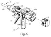
図1は、ハンドルアセンブリ(11)及び取り外し可能なシャフトアセンブリ(16)を含む、モータ駆動の外科用切断及び締結器具(10)である。いくつかのバージョンでは、ハンドルアセンブリ(11)及びシャフトアセンブリ(16)はそれぞれ、1回しか使えない使い捨て構成要素として提供される。いくつかの他のバージョンでは、ハンドルアセンブリ(11)及びシャフトアセンブリ(16)はそれぞれ、再利用可能構成要素として提供される。別の単なる例として、シャフトアセンブリ(16)が1回しか使えない使い捨て構成要素として提供される一方、ハンドルアセンブリは再利用可能構成要素として提供されてもよい。ハンドルアセンブリ(11)及びシャフトアセンブリ(16)の再利用可能バージョンの様々な好適な方法が、本明細書の教示に鑑み、当業者に明らかになるであろう。I. Exemplary Surgical Instrument Overview FIG. 1 is a motorized surgical cutting and fastening instrument (10) that includes a handle assembly (11) and a removable shaft assembly (16). In some versions, the handle assembly (11) and shaft assembly (16) are each provided as single use disposable components. In some other versions, the handle assembly (11) and shaft assembly (16) are each provided as reusable components. As another example only, the handle assembly may be provided as a reusable component while the shaft assembly (16) is provided as a single use disposable component. Various suitable methods of reusable versions of handle assembly (11) and shaft assembly (16) will be apparent to those skilled in the art in view of the teachings herein.
本実施例のハンドルアセンブリ(11)は、筐体(12)、閉鎖トリガ(32)、及び発射トリガ(33)を含む。筐体(12)の少なくとも一部は、臨床医によって把持、操作、及び作動されるように構成されたハンドル(14)を形成する。筐体(12)は、シャフトアセンブリ(16)に動作可能に取り付けられるように構成されており、シャフトアセンブリ(16)は外科用エンドエフェクタ(18)に動作可能に連結される。後述するように、エンドエフェクタ(18)は、1つ以上の外科的タスク又は処置を実行するように構成される。具体的には、図1に示される実施例のエンドエフェクタ(18)は、従来のエンドカッターのエンドエフェクタと同様の方法で外科的切断及びステープル留め処置を実行するように動作可能であるが、これは単なる例示にすぎない。 Handle assembly (11) of the present example includes a housing (12), a closure trigger (32), and a firing trigger (33). At least a portion of housing (12) forms a handle (14) configured to be grasped, manipulated and actuated by a clinician. Housing (12) is configured to be operably attached to shaft assembly (16), which is operably coupled to surgical end effector (18). As described below, end effector (18) is configured to perform one or more surgical tasks or procedures. Specifically, the end effector (18) of the example shown in FIG. 1 is operable to perform surgical cutting and stapling procedures in a manner similar to the end effector of a conventional endocutter, This is just an example.
図1は、交換式シャフトアセンブリ(16)がハンドルアセンブリ(11)に動作可能に連結された、外科用器具(10)を示す。図2、3は、ハンドル(14)の筐体(12)への交換式シャフトアセンブリ(16)の取り付けを示す。ハンドル(14)は、ねじ、スナップ機構、接着剤などで相互連結され得る一対の相互連結可能なハンドル筐体セグメント(22、24)を含む。図示の構成において、ハンドル筐体セグメント(22、24)は協働して、臨床医によって握持及び操作され得るピストルグリップ部分(26)を形成する。以下で更に詳細に考察されるように、ハンドル(14)は、その中に複数の駆動システムを動作可能に支持し、それら駆動システムは、それに動作可能に取り付けられた交換式シャフトアセンブリ(16)の対応する部分に対して、様々な制御運動を生成及び適用するように構成されている。更に詳細に後述するように、トリガ(32、33)は、ピストルグリップ部分(26)に向かって枢動可能であり、ハンドル(14)内の駆動システムの少なくとも一部を起動する。 FIG. 1 shows a surgical instrument (10) with an interchangeable shaft assembly (16) operably coupled to a handle assembly (11). Figures 2 and 3 show the attachment of the replaceable shaft assembly (16) to the housing (12) of the handle (14). Handle (14) includes a pair of interconnectable handle housing segments (22, 24) that may be interconnected with screws, snap mechanisms, adhesives, or the like. In the illustrated configuration, handle housing segments (22, 24) cooperate to form a pistol grip portion (26) that can be grasped and manipulated by a clinician. As will be discussed in more detail below, the handle (14) operatively supports therein a plurality of drive systems which are operably attached to interchangeable shaft assemblies (16). are configured to generate and apply various control motions to corresponding portions of the . As will be described in more detail below, triggers (32, 33) are pivotable toward pistol grip portion (26) to activate at least a portion of the drive system within handle (14).
ハンドルアセンブリ(11)内の駆動システムの少なくともいくつかは、最終的に、図5に概略的に示されるモータ(118)によって駆動される。本実施例では、モータ(118)はピストルグリップ部分(26)内に位置しているが、モータ(118)は任意の他の好適な位置に配置されてもよいことを理解されたい。モータ(118)は、ハンドル(14)に固定されたバッテリパック(110)から給電される。本実施例では、図5に示すように、バッテリパック(110)がハンドル(14)から取り外し可能である。いくつかの他のバージョンでは、バッテリパック(110)は、ハンドル(14)から取り外し不能である。いくつかのかかるバージョンでは、バッテリパック(110)(又はその変形)は、ハンドル筐体セグメント(22、24)内に完全に収容される。モータ(118)及びバッテリパック(110)が取り得る様々な好適な形態は、本明細書の教示に鑑み、当業者に明らかになるであろう。 At least some of the drive system within the handle assembly (11) is ultimately driven by a motor (118) shown schematically in FIG. In the present example, motor (118) is located within pistol grip portion (26), but it should be understood that motor (118) may be located in any other suitable location. The motor (118) is powered by a battery pack (110) fixed to the handle (14). In this embodiment, as shown in Figure 5, the battery pack (110) is removable from the handle (14). In some other versions, battery pack (110) is not removable from handle (14). In some such versions, the battery pack (110) (or variations thereof) is contained entirely within the handle housing segments (22, 24). Various suitable forms that motor (118) and battery pack (110) may take will be apparent to those skilled in the art in view of the teachings herein.
図5に概略的に示されるように、制御回路(117)は、ハンドル(14)内に収容される。単なる例として、制御回路(117)は、本明細書における教示に鑑み、当業者に明らかになるように、マイクロコントローラ及び/又は他の各種構成要素から構成され得る。制御回路(117)は、モータ(118)を駆動するために制御アルゴリズムを記憶及び実行するように構成されている。図5及び図7にも示されるように、ハンドル(14)は、制御回路(117)と通信するエンコーダ(115)を含む。エンコーダ(115)は、長手方向駆動部材(86)上に位置する複数のマーキング(85)を読み取るように構成されている。各マーキング(85)は、長手方向駆動部材(86)の対応する長手方向位置と関連付けられる。更に、上述したように、モータ(118)は、長手方向駆動部材(86)を作動させるように動作可能である。例えば、モータ(118)が回転すると、モータ(118)はアイドラーギヤ(119)を回転させることができ、このギヤは次に、長手方向駆動部材(86)の歯(88)と噛合することによって長手方向駆動部材(86)を直線方向に作動させる。したがって、モータ(118)が長手方向駆動部材(86)を作動させると、エンコーダ(115)は、長手方向駆動部材(86)上のマーキング(85)を読み取り、長手方向駆動部材(86)の長手方向位置を追跡及び判定することができる。エンコーダ(115)は、制御アルゴリズムを適切に実行するために、この情報を制御回路(117)に通信してもよい。 As shown schematically in Figure 5, the control circuit (117) is housed within the handle (14). Merely by way of example, control circuitry (117) may be comprised of a microcontroller and/or various other components, as would be apparent to one of ordinary skill in the art in view of the teachings herein. Control circuitry (117) is configured to store and execute control algorithms for driving motor (118). As also shown in Figures 5 and 7, the handle (14) includes an encoder (115) that communicates with a control circuit (117). The encoder (115) is configured to read a plurality of markings (85) located on the longitudinal drive member (86). Each marking (85) is associated with a corresponding longitudinal position of the longitudinal drive member (86). Further, as noted above, motor (118) is operable to actuate longitudinal drive member (86). For example, as motor (118) rotates, motor (118) may rotate idler gear (119), which in turn engages teeth (88) of longitudinal drive member (86) to The longitudinal drive member (86) is actuated linearly. Thus, when motor (118) actuates longitudinal drive member (86), encoder (115) reads markings (85) on longitudinal drive member (86) to determine the length of longitudinal drive member (86). Directional position can be tracked and determined. The encoder (115) may communicate this information to the control circuit (117) for proper execution of the control algorithm.
本実施例では、エンコーダ(115)及びマーキング(85)を使用して、長手方向駆動部材(86)の長手方向位置を判定するが、任意の他の好適な構成要素を使用して、長手方向駆動部材(86)の長手方向位置を追跡及び判定してもよい。単なる別の例として、ステッピングモータを利用して、長手方向駆動部材(86)の長手方向位置の正確な制御を提供するように長手方向駆動部材(86)を駆動することができる。 In the present example, the encoder (115) and markings (85) are used to determine the longitudinal position of the longitudinal drive member (86), although any other suitable component may be used to The longitudinal position of the drive member (86) may be tracked and determined. As just another example, a stepper motor can be utilized to drive the longitudinal drive member (86) to provide precise control of the longitudinal position of the longitudinal drive member (86).
制御回路(117)はまた、ハンドルアセンブリ(11)の近位端に位置するグラフィカルユーザインターフェース(116)を駆動するように構成されている。いくつかのバージョンでは、制御回路(117)は、シャフトアセンブリ(16)から1つ以上の信号を受信及び処理するように構成されている。単なる例として、制御回路(117)は、その開示内容が参照により本明細書に組み込まれる、2015年10月1日に公開された、米国特許公開第2015/0272575号、名称「Surgical Instrument Comprising a Sensor System」の教示の少なくとも一部に従って構成され、かつ動作可能であり得る。制御回路(117)が構成され、動作可能であり得る他の好適な方法は、本明細書の教示に鑑み、当業者に明らかになるであろう。 Control circuitry (117) is also configured to drive a graphical user interface (116) located at the proximal end of handle assembly (11). In some versions, control circuitry (117) is configured to receive and process one or more signals from shaft assembly (16). Merely by way of example, the control circuit (117) is described in U.S. Patent Publication No. 2015/0272575, entitled "Surgical Instrument Composing a Instrument," published Oct. 1, 2015, the disclosure of which is incorporated herein by reference. may be constructed and operable in accordance with at least some of the teachings of the "Sensor System". Other suitable ways in which control circuitry (117) may be configured and operable will be apparent to those skilled in the art in view of the teachings herein.
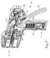
図3で最も良く分かるように、ハンドル(14)のフレーム(28)は、複数の駆動システムを動作可能に支持する。この特定の実施例では、フレーム(28)は、全体として(30)と示される「第1の」又は閉鎖駆動システムを動作可能に支持し、その閉鎖駆動システムは、そこに動作可能に取り付けられた又は連結された交換式シャフトアセンブリ(16)に閉鎖及び開放運動を適用するために用いられ得る。また、この特定の実施例において、閉鎖駆動システム(30)は、フレーム(28)によって枢動可能に支持される閉鎖トリガ(32)の形態のアクチュエータを含む。より具体的には、閉鎖トリガ(32)は、ピン(図示せず)によって筐体(14)に枢動可能に連結される。かかる配置により、臨床医が閉鎖トリガ(32)を操作することができるため、臨床医がハンドル(14)のピストルグリップ部分(26)を把持すると、閉鎖トリガ(32)が、開始位置又は「非作動」位置(図4A)からピストルグリップ部分(26)に向かって「作動」位置へ、より具体的には、完全圧縮位置又は完全作動位置(図4B)へと容易に枢動され得る。閉鎖トリガ(32)は、ばね又は他の付勢構成(図示せず)によって非作動位置へと付勢されてもよい。 As best seen in Figure 3, the frame (28) of the handle (14) operatively supports a plurality of drive systems. In this particular example, frame (28) operatively supports a "first" or closure drive system, generally designated (30), which closure drive system is operatively attached thereto. It can be used to apply closing and opening motions to an alternate or coupled interchangeable shaft assembly (16). Also, in this particular embodiment, closure drive system (30) includes an actuator in the form of a closure trigger (32) pivotally supported by frame (28). More specifically, closure trigger (32) is pivotally coupled to housing (14) by a pin (not shown). Such an arrangement allows the clinician to manipulate the closure trigger (32) such that when the clinician grasps the pistol grip portion (26) of the handle (14), the closure trigger (32) is in the starting position or "non It can be easily pivoted from the "activated" position (Fig. 4A) towards the pistol grip portion (26) to the "activated" position, more specifically to the fully compressed or fully activated position (Fig. 4B). The closure trigger (32) may be biased to the unactuated position by a spring or other biasing arrangement (not shown).
本実施例において、閉鎖駆動システム(30)は、閉鎖トリガ(32)に枢動可能に連結された閉鎖連結アセンブリ(36)を更に含む。閉鎖連結アセンブリ(36)の一部を図3に示す。閉鎖連結アセンブリ(36)は、ピン(図示せず)によって閉鎖トリガ(32)に枢動可能に連結された第1の閉鎖リンク(図示せず)と第2の閉鎖リンク(38)とを含んでもよい。第2の閉鎖リンク(38)はまた、本明細書において「取り付け部材」とも称され得、横断取り付けピン(42)を含んでもよい。図3に示すように、取り付けピン(42)は、シャフトアセンブリ(16)がハンドルアセンブリ(11)から取り外されたときに露出される。したがって、取り付けピン(42)は、以下により詳細に記載されるように、シャフトアセンブリ(16)がハンドルアセンブリ(11)と連結されているとき、シャフトアセンブリ(16)の相補的機構と連結されてもよい。 In the present example, closure drive system (30) further includes a closure coupling assembly (36) pivotally coupled to closure trigger (32). A portion of the closure linkage assembly (36) is shown in FIG. A closure coupling assembly (36) includes a first closure link (not shown) and a second closure link (38) pivotally connected to the closure trigger (32) by a pin (not shown). It's okay. The second closure link (38) may also be referred to herein as an "attachment member" and may include a transverse attachment pin (42). As shown in FIG. 3, mounting pin (42) is exposed when shaft assembly (16) is removed from handle assembly (11). Accordingly, mounting pin (42) is coupled with complementary features of shaft assembly (16) when shaft assembly (16) is coupled with handle assembly (11), as described in more detail below. good too.
更に図1~3を参照すると、第1の閉鎖リンク(図示せず)は、フレーム(28)に枢動可能に連結された閉鎖解放アセンブリ(44)と協働するように構成されている。少なくとも1つの例において、閉鎖解放アセンブリ(44)は、解放ボタンアセンブリ(46)を有し、遠位方向に突出するロッキングポール(図示せず)がその上に形成される。解放ボタンアセンブリ(46)は、解放ばね(図示せず)によって反時計回りの方向に枢動し得る。臨床医が、閉鎖トリガ(32)を非作動位置からハンドル(14)のピストルグリップ部分(26)に向かって押下すると、第1の閉鎖リンク(図示せず)は、ロッキングポール(図示せず)が第1の閉鎖リンク(図示せず)と保持係合する点に向かって上向きに枢動し、それにより、閉鎖トリガ(32)が非作動位置に戻ることを防ぐ。したがって、閉鎖解放アセンブリ(44)は、閉鎖トリガ(32)を完全作動位置でロックする働きをする。 Still referring to FIGS. 1-3, a first closure link (not shown) is configured to cooperate with a closure release assembly (44) pivotally coupled to frame (28). In at least one example, the closure release assembly (44) has a release button assembly (46) with a distally projecting locking pole (not shown) formed thereon. Release button assembly (46) may be pivoted in a counterclockwise direction by a release spring (not shown). When the clinician depresses the closure trigger (32) from the unactuated position toward the pistol grip portion (26) of the handle (14), the first closure link (not shown) engages the locking pole (not shown). pivots upward toward a point in retaining engagement with a first closure link (not shown), thereby preventing closure trigger (32) from returning to its unactuated position. The closure release assembly (44) thus serves to lock the closure trigger (32) in the fully actuated position.
臨床医が、閉鎖トリガ(32)を作動位置からロック解除して非作動位置に戻そうとするとき、臨床医は単純に、閉鎖解放ボタンアセンブリ(46)を遠位方向に付勢することによって閉鎖解放ボタンアセンブリ(46)を枢動させるだけで、ロッキングポール(図示せず)は第1の閉鎖リンク(図示せず)との係合から外れるように移動する。ロッキングポール(図示せず)が第1の閉鎖リンク(図示せず)との係合から外れると、閉鎖トリガ(32)は、閉鎖トリガ(32)を付勢して非作動位置に戻す弾性付勢に応答して、非作動位置に戻ることができる。他の閉鎖トリガロック及び解放構成が用いられてもよい。 When the clinician wishes to unlock the closure trigger (32) from the actuated position and return it to the non-actuated position, the clinician simply pushes the closure release button assembly (46) distally. Simply pivoting the closure release button assembly (46) moves the locking pawl (not shown) out of engagement with the first closure link (not shown). When the locking pawl (not shown) is disengaged from the first closure link (not shown), the closure trigger (32) is resiliently biased to return the closure trigger (32) to the non-actuated position. It can return to the non-actuated position in response to a force. Other closure trigger lock and release configurations may be used.
交換式シャフトアセンブリ(16)は、シャフトアセンブリ(16)の長手方向軸に対して所望の位置にエンドエフェクタ(18)を解放可能に保持するように構成され得る、関節ジョイント(52)と関節ロック(図示せず)とを更に含む。本実施例では、関節ジョイント(52)は、当技術分野において既知のように、エンドエフェクタ(18)がシャフトアセンブリ(16)の長手方向軸から離れる方向に横方向に偏向され得るように構成されている。あくまで一例として、エンドエフェクタ(18)、関節ジョイント(52)、及び関節ロック(図示せず)は、2014年9月18日に公開された米国特許公開第2014/0263541号の名称「Articulatable Surgical Instrument Comprising an Articulation Lock」の教示の少なくとも一部に従って構成され、かつ動作可能であり得る。 The interchangeable shaft assembly (16) includes an articulation joint (52) and an articulation lock that may be configured to releasably retain the end effector (18) in a desired position relative to the longitudinal axis of the shaft assembly (16). (not shown). In the present example, articulation joint (52) is configured such that end effector (18) can be laterally deflected away from the longitudinal axis of shaft assembly (16), as is known in the art. ing. By way of example only, the end effector (18), articulation joint (52), and articulation lock (not shown) are described in U.S. Patent Publication No. 2014/0263541, published September 18, 2014, entitled "Articulatory Surgical Instrument." may be constructed and operable in accordance with, at least in part, the teachings of Comprising an Articulation Lock.
本実施例では、関節ジョイント(52)における関節運動は、ハンドルアセンブリ(11)上の関節制御ロッカー(112)を介した操作者からの制御入力に基づいて、モータ(118)を介してモータ駆動される。単になる例として、操作者が関節制御ロッカー(112)の上部を押すと、エンドエフェクタ(18)は、関節ジョイント(52)において(上方から器具(10)を見て)横方向右方に枢動することができる。操作者が関節制御ロッカー(112)の下部を押すと、エンドエフェクタ(18)は、関節ジョイント(52)において(上方から器具(10)を見て)横方向左方に枢動することができる。いくつかのバージョンでは、ハンドルアセンブリ(11)の他方の側は、別の関節制御ロッカー(112)を含む。かかるバージョンでは、ハンドルアセンブリ(11)の他方の側の関節制御ロッカー(112)は、関節制御ロッカー(112)の上部作動及び関節制御ロッカー(112)の下部作動に応答して、上述の方向と反対の方向にエンドエフェクタ(18)を枢動させるように構成されてもよい。単なる一例として、関節ジョイント(52)におけるエンドエフェクタ(18)の電動関節運動を提供する関節制御ロッカー(112)と機構の残りの部分は、その開示内容が参照により本明細書に組み込まれる、2015年10月1日に公開された、米国特許公開第2015/0280384号、名称「Surgical Instrument Comprising a Rotatable Shaft」の教示の少なくとも一部に従って構成され、かつ動作可能であり得る。関節ジョイント(52)におけるエンドエフェクタ(18)の電動関節運動を提供する関節制御ロッカー(112)と機構の残りの部分が構成され、かつ動作可能であり得る他の好適な方法は、本明細書の教示に鑑み、当業者に明らかとなるであろう。 In the present example, articulation at articulation joint (52) is motorized via motor (118) based on control input from the operator via articulation control rocker (112) on handle assembly (11). be done. By way of example only, when the operator presses the top of articulation control rocker (112), end effector (18) pivots laterally to the right (viewing instrument (10) from above) at articulation joint (52). can move. When the operator presses the lower portion of the articulation control rocker (112), the end effector (18) can pivot laterally to the left (viewing the instrument (10) from above) at the articulation joint (52). . In some versions, the other side of the handle assembly (11) includes another articulation control rocker (112). In such versions, the articulation control rocker (112) on the other side of the handle assembly (11) is responsive to actuation of the articulation control rocker (112) upper and actuation of the articulation control rocker (112) lower in the directions and directions described above. It may be configured to pivot the end effector (18) in the opposite direction. Merely by way of example, articulation control rocker (112) and the rest of the mechanism that provide motorized articulation of end effector (18) at articulation joint (52), the disclosure of which is incorporated herein by reference, 2015 It may be constructed and operable in accordance with, at least in part, the teachings of U.S. Patent Publication No. 2015/0280384, entitled “Surgical Instrument Comprising a Rotatable Shaft,” published Oct. 1, 2015. Other suitable ways in which the articulation control rocker (112) and the remainder of the mechanism that provide motorized articulation of the end effector (18) at the articulation joint (52) may be configured and operable are described herein. will become apparent to those skilled in the art in view of the teachings of
本実施例のエンドエフェクタ(18)は、ステープルカートリッジ(20)を動作可能に支持するように構成された細長いチャネル(48)の形態の下部ジョーを備える。本実施例のエンドエフェクタ(18)は、細長いチャネル(48)に対して枢動可能に支持されるアンビル(50)の形態の上部ジョーを更に含む。交換式シャフトアセンブリ(16)は、ノズル部分(56、58)で構成される近位筐体又はノズル(54)と、エンドエフェクタ(18)のアンビル(50)を閉鎖及び/又は開放するために利用され得る閉鎖管(60)と、を更に含む。シャフトアセンブリ(16)は、シャフトアセンブリ(16)内のシャーシ(64)内で摺動可能に支持される閉鎖シャトル(62)を更に含み、閉鎖シャトル(62)はシャーシ(64)に対して軸方向に移動され得る。閉鎖シャトル(62)は、第2の閉鎖リンク(38)に取り付けられた取り付けピン(42)への取り付けのために構成されている、近位に突出する一対のフック(66)を含む。閉鎖管(60)の近位端(図示せず)は、閉鎖シャトル(62)に対する相対回転のために閉鎖シャトル(62)に連結されているが、閉鎖管(60)と閉鎖シャトル(62)との連結により、閉鎖管(60)及び閉鎖シャトル(62)は互いに長手方向に並進する。閉鎖ばね(図示せず)が閉鎖管(60)上に軸支され、閉鎖管(60)を近位方向(PD)に付勢する働きをし、それによって、シャフトアセンブリ(16)がハンドル(14)に動作可能に連結されたとき、閉鎖トリガ(32)を非作動位置へと枢動させる働きをし得る。 End effector (18) of the present example comprises a lower jaw in the form of an elongated channel (48) configured to operatively support staple cartridge (20). End effector (18) of the present example further includes an upper jaw in the form of an anvil (50) that is pivotally supported relative to elongated channel (48). Interchangeable shaft assembly (16) includes a proximal housing or nozzle (54) comprising nozzle portions (56, 58) and anvil (50) of end effector (18) for closing and/or opening. and a closed tube (60) that may be utilized. Shaft assembly (16) further includes a closure shuttle (62) slidably supported within chassis (64) within shaft assembly (16), closure shuttle (62) pivoting relative to chassis (64). direction can be moved. Closure shuttle (62) includes a pair of proximally projecting hooks (66) configured for attachment to mounting pins (42) attached to second closure link (38). A proximal end (not shown) of closure tube (60) is coupled to closure shuttle (62) for relative rotation to closure shuttle (62), although closure tube (60) and closure shuttle (62) are not connected. , the closure tube (60) and closure shuttle (62) translate longitudinally relative to each other. A closure spring (not shown) is journalled on the closure tube (60) and serves to bias the closure tube (60) in a proximal direction (PD), thereby allowing the shaft assembly (16) to engage the handle ( 14) may serve to pivot the closure trigger (32) to an unactuated position.
本例において、関節ジョイント(52)は、二重枢動閉鎖スリーブアセンブリ(70)を含む。二重枢動閉鎖スリーブアセンブリ(70)は、その開示内容が参照により本明細書に組み込まれる米国特許公開第2014/0263541号に記載される様々な様式で、アンビル(50)の開放タブと係合するためのエンドエフェクタ閉鎖スリーブアセンブリ(72)を含む。二重枢動閉鎖スリーブアセンブリ(70)は、関節ジョイント(52)が関節運動状態にあるとき(すなわち、エンドエフェクタ(18)が、関節ジョイント(52)においてシャフトアセンブリ(16)の長手方向軸から離れる方向に枢動可能に偏向するとき)でも、閉鎖トリガ(32)の枢動運動に応答して閉鎖管(60)と共に並進するように閉鎖管(60)と連結される。更に、エンドエフェクタ閉鎖スリーブアセンブリ(72)とアンビル(50)との係合は、二重枢動閉鎖スリーブアセンブリ(70)及び閉鎖管(60)の遠位並進に応答して、アンビル(50)をステープルカートリッジ(20)に向かって枢動させることと、二重枢動閉鎖スリーブアセンブリ(70)及び閉鎖管(60)の近位並進に応答して、アンビル(50)をステープルカートリッジ(20)から離れるように枢動させることと、提供する。本例のシャフトアセンブリ(16)は関節ジョイント(52)を含むが、他の交換式シャフトアセンブリは、関節動作能力を欠いていてもよい。 In the present example, articulation joint (52) includes a double pivot closure sleeve assembly (70). The dual pivot closure sleeve assembly (70) engages the opening tabs of the anvil (50) in various manners as described in U.S. Patent Publication No. 2014/0263541, the disclosure of which is incorporated herein by reference. an end effector closure sleeve assembly (72) for mating. Dual pivoting closure sleeve assembly (70) is configured such that when articulation joint (52) is in articulation (i.e., end effector (18) moves from the longitudinal axis of shaft assembly (16) at articulation joint (52)). When pivotally deflected away), it is coupled with closure tube (60) to translate therewith in response to pivotal movement of closure trigger (32). Further, engagement of end effector closure sleeve assembly (72) with anvil (50) may cause anvil (50) to move in response to distal translation of dual pivot closure sleeve assembly (70) and closure tube (60). toward staple cartridge (20) and proximal translation of dual pivot closure sleeve assembly (70) and closure tube (60), anvil (50) toward staple cartridge (20). pivoting away from and providing. Although shaft assembly (16) of the present example includes an articulation joint (52), other interchangeable shaft assemblies may lack articulation capability.
図3に示されるように、シャーシ(64)は、シャーシ(64)上に形成された一対の先細取り付け部分(74)を含み、これらの取り付け部分は、フレーム(28)の遠位取り付けフランジ部分(78)に形成された対応するダブテールスロット(76)に受容されるように適合されている。各ダブテールスロット(76)は、取り付け部分(74)を中に配置して受容するように、先細であってもよく、又は略V字形であってもよい。シャフト取り付けラグ(80)が、中間発射シャフト(82)の近位端上に形成される。したがって、交換式シャフトアセンブリ(16)がハンドル(14)に連結されたとき、シャフト取り付けラグ(80)は、長手方向駆動部材(86)の遠位端に形成された発射シャフト取り付けクレードル(84)内に受容される。シャフト取り付けラグ(80)が発射シャフト取り付けクレードル(84)内に受容されると、中間発射シャフト(82)は長手方向駆動部材(86)と共に長手方向に並進する。当該技術において既知なように、中間発射シャフト(82)が遠位方向に並進すると、中間発射シャフト(82)はエンドエフェクタ(18)を作動させて、ステープルを組織内に駆動し組織を切断させる。単なる例として、エンドエフェクタ(18)の作動は、その開示内容が参照により本明細書に組み込まれる米国特許公開第2015/0280384号の教示の少なくとも一部、及び/又は本明細書に引用される様々な他の参考文献の教示に従って実行され得る。 As shown in FIG. 3, chassis (64) includes a pair of tapered mounting portions (74) formed on chassis (64) that connect to distal mounting flange portions of frame (28). It is adapted to be received in a corresponding dovetail slot (76) formed in (78). Each dovetail slot (76) may be tapered or generally V-shaped to receive the mounting portion (74) disposed therein. A shaft mounting lug (80) is formed on the proximal end of intermediate firing shaft (82). Thus, when interchangeable shaft assembly (16) is coupled to handle (14), shaft mounting lugs (80) are aligned with firing shaft mounting cradle (84) formed at the distal end of longitudinal drive member (86). accepted within. When shaft mounting lug (80) is received within firing shaft mounting cradle (84), intermediate firing shaft (82) longitudinally translates with longitudinal drive member (86). As intermediate firing shaft (82) translates distally, intermediate firing shaft (82) actuates end effector (18) to drive staples into and cut tissue, as is known in the art. . Merely by way of example, actuation of the end effector (18) is at least partially taught in U.S. Patent Publication No. 2015/0280384, the disclosure of which is incorporated herein by reference, and/or cited herein. It can be carried out according to the teachings of various other references.
図4A~4Cは、エンドエフェクタ(18)の異なる作動状態におけるハンドルアセンブリ(11)の異なる状態を示す。図4Aでは、ハンドルアセンブリ(11)は、閉鎖トリガ(32)が非作動枢動位置にあり、発射トリガ(33)が非作動枢動位置にある状態にある。この段階で、エンドエフェクタ(18)は、アンビル(50)がステープルカートリッジ(20)から離れるように枢動される開放状態にある。 Figures 4A-4C show different states of handle assembly (11) in different operating states of end effector (18). In FIG. 4A, the handle assembly (11) is with the closure trigger (32) in the non-actuated pivoted position and the firing trigger (33) in the non-actuated pivoted position. At this stage, end effector (18) is in an open state with anvil (50) pivoted away from staple cartridge (20).
図4Bでは、ハンドルアセンブリ(11)は、閉鎖トリガ(32)が作動枢動位置にある状態にある。上述したように、閉鎖トリガ(32)は、操作者が解放ボタンアセンブリ(46)を作動させるまで、この位置でロックされる。この段階では、エンドエフェクタは、アンビル(50)がステープルカートリッジ(20)に向かって枢動し、組織がアンビル(50)とカートリッジ(20)との間で圧縮されるように、閉鎖されているが未発射状態にある。しかしながら、発射シャフト(82)は、ステープルをステープルカートリッジ(20)から作動させるように遠位方向にまだ駆動されておらず、発射シャフト(82)の遠位端のナイフは、アンビル(20)とステープルカートリッジ(20)との間で組織を切断していない。発射トリガ(33)は、非作動枢動位置から作動枢動位置への閉鎖トリガ(32)の移動により、図4Bにおいては部分作動枢動位置にあることに留意されたい。しかしながら、この発射トリガ(33)の移動は、操作者の発射トリガ(33)へのアクセスを改善するためにのみ行われる。換言すれば、この図4Aに示す位置から図4Bに示す位置への発射トリガ(33)の移動は、まだ発射シーケンスを起動していない。 In Figure 4B, the handle assembly (11) is with the closure trigger (32) in the actuated pivot position. As noted above, closure trigger (32) is locked in this position until the operator actuates release button assembly (46). At this stage, the end effector is closed such that anvil (50) is pivoted toward staple cartridge (20) and tissue is compressed between anvil (50) and cartridge (20). is not fired. However, firing shaft (82) has not yet been driven distally to actuate staples from staple cartridge (20), and the knife at the distal end of firing shaft (82) is engaged with anvil (20). No tissue has been cut between the staple cartridge (20). Note that the firing trigger (33) is in the partially actuated pivot position in Figure 4B due to movement of the closure trigger (32) from the unactuated pivot position to the actuated pivot position. However, this movement of the firing trigger (33) is done only to improve the operator's access to the firing trigger (33). In other words, this movement of the firing trigger (33) from the position shown in Figure 4A to the position shown in Figure 4B has not yet initiated a firing sequence.
図4Cでは、ハンドルアセンブリは、閉鎖トリガ(32)が作動枢動位置に留まり、発射トリガ(33)が作動枢動位置まで既に枢動している状態にある。この発射トリガ(33)の作動により、モータ(118)が作動して、長手方向駆動部材(86)を長手方向に駆動させ、これにより、発射シャフト(82)が長手方向に駆動される。発射シャフト(82)が長手方向に移動する結果、ステープルは、ステープルカートリッジ(20)からアンビル(50)とステープルカートリッジ(20)との間で圧縮された組織まで作動し、更に、アンビル(50)とステープルカートリッジ(20)との間の圧縮組織を切断する。いくつかのバージョンでは、追加の安全トリガが提供される。例えば、追加の安全トリガは、安全トリガが作動するまで、発射トリガ(33)の作動を防止することができる。換言すれば、図4Bに示す状態に到達した後、操作者は、発射トリガ(33)を作動させる準備ができると、最初に安全トリガを作動させ、次いで発射トリガ(33)を作動させなければならない。安全トリガの存在は、発射トリガ(33)の偶発的な作動を防止し得る。 In Figure 4C, the handle assembly is in a state in which the closure trigger (32) remains in the actuated pivoted position and the firing trigger (33) has already pivoted to the actuated pivoted position. This actuation of firing trigger (33) actuates motor (118) to longitudinally drive longitudinal drive member (86), which in turn longitudinally drives firing shaft (82). Longitudinal movement of firing shaft (82) results in staples being actuated from staple cartridge (20) to tissue compressed between anvil (50) and staple cartridge (20), and further through anvil (50). and the staple cartridge (20). Some versions offer additional safety triggers. For example, an additional safety trigger may prevent activation of the firing trigger (33) until the safety trigger is activated. In other words, after reaching the state shown in FIG. 4B, when the operator is ready to actuate the firing trigger (33), he must first actuate the safety trigger and then the firing trigger (33). not. The presence of the safety trigger may prevent accidental actuation of the firing trigger (33).
また、本実施例では、アンビル(50)のステープルカートリッジ(20)に向かう作動が、閉鎖トリガ(32)とアンビル(50)との間の純粋な機械的連結を通じて提供されており、アンビル(50)を作動させるためにモータ(118)が使用されないことも理解されたい。また、本実施例では、発射シャフト(82)の作動(ひいては、ステープルカートリッジ(20)の作動)は、モータ(118)の起動を通じても提供されることを理解されたい。加えて、関節ジョイント(52)の作動は、本実施例ではモータ(118)の起動を通じて提供される。この関節ジョイント(52)の電動作動は、駆動部材(86)の長手方向並進を介して提供される。シャフトアセンブリ(16)内のクラッチアセンブリ(図示せず)は、駆動部材(86)の長手方向の並進を、関節ジョイント(52)を駆動する、又はステープルカートリッジ(20)を作動させる機構と選択的に結合するように動作可能である。クラッチアセンブリを介したこのような選択的結合は、閉鎖トリガ(32)の枢動位置に基づく。具体的には、閉鎖トリガ(32)が図4Aに示される非作動位置にあるとき、モータ(118)は(関節制御ロッカー(112)の起動に応答して)起動し、関節ジョイント(52)を駆動する。閉鎖トリガ(32)が図4Bに示される作動位置にあるとき、モータ(118)は(発射トリガ(33)の作動に応答して)起動し、ステープルカートリッジ(20)を作動させる。単なる例として、クラッチアセンブリは、その開示内容が参照により本明細書に組み込まれる米国特許公開第2015/0280384号の教示の少なくとも一部に従って構成され、かつ動作可能であり得る。 Also, in the present example, actuation of anvil (50) toward staple cartridge (20) is provided through a purely mechanical connection between closure trigger (32) and anvil (50); ) is not used to actuate the motor (118). It should also be understood that, in the present example, actuation of firing shaft (82) (and thus staple cartridge (20)) is also provided through actuation of motor (118). Additionally, actuation of articulation joint (52) is provided through actuation of motor (118) in the present example. Motorized actuation of this articulation joint (52) is provided via longitudinal translation of the drive member (86). A clutch assembly (not shown) within shaft assembly (16) selectively couples longitudinal translation of drive member (86) with a mechanism that drives articulation joint (52) or actuates staple cartridge (20). is operable to couple to Such selective engagement via the clutch assembly is based on the pivotal position of the closure trigger (32). Specifically, when closure trigger (32) is in the non-actuated position shown in FIG. 4A, motor (118) activates (in response to activation of articulation control rocker (112)) causing articulation joint (52) to move. to drive. When closure trigger (32) is in the actuated position shown in FIG. 4B, motor (118) is activated (in response to actuation of firing trigger (33)) to actuate staple cartridge (20). By way of example only, the clutch assembly may be constructed and operable in accordance with at least some of the teachings of US Patent Publication No. 2015/0280384, the disclosure of which is incorporated herein by reference.
本実施例では、ハンドルアセンブリ(11)は、「ホーム」ボタン(114)も含む。単なる例として、アンビル(50)が閉鎖位置にあるとき、「ホーム」ボタン(114)は、モータ(118)を作動させて、駆動部材(86)を最も近位の「ホーム」位置まで近位まで後退させるように動作可能であり得る。これに加えて又はこの代わりに、アンビル(50)が開放位置にあるとき、「ホーム」ボタン(114)は、モータ(118)を始動して関節ジョイント(52)を駆動し、エンドエフェクタ(18)がシャフトアセンブリ(16)と同軸に位置合わせされる非作動状態を達成するように動作可能であり得る。これに加えて又はこの代わりに、「ホーム」ボタン(114)は、グラフィカルユーザインターフェース(116)を起動して、「ホーム」画面に戻ることができる。「ホーム」ボタン(114)の関節運動に応答して提供され得るその他の好適な動作は、本明細書の教示に鑑み、当業者に明らかになるであろう。 In the present example, handle assembly (11) also includes a "home" button (114). By way of example only, when anvil (50) is in the closed position, "home" button (114) activates motor (118) to move drive member (86) proximally to its most proximal "home" position. may be operable to retract to. Additionally or alternatively, when anvil (50) is in the open position, "home" button (114) activates motor (118) to drive articulation joint (52) and end effector (18). ) is coaxially aligned with the shaft assembly (16) to achieve a non-actuated state. Additionally or alternatively, the "Home" button (114) may launch a graphical user interface (116) to return to the "Home" screen. Other suitable actions that may be provided in response to articulation of "home" button (114) will be apparent to those skilled in the art in view of the teachings herein.
本実施例のシャフトアセンブリ(16)は、シャフトアセンブリ(16)をハンドルアセンブリ(11)、より具体的には、フレーム(28)に着脱可能に連結するためのラッチシステムを更に含む。単なる例として、このラッチシステムは、シャーシ(64)に移動可能に連結されたロックヨーク又は他の種類のロック部材を含んでもよい。図3に示すように、かかるロックヨークは、フレーム(28)内の対応するロック戻り止め又は溝(98)と解除可能に係合するように構成された2つの近位突出ロックラグ(96)を含んでもよい。いくつかのバージョンでは、ロックヨークは、弾性部材(例えば、ばねなど)によって近位方向に付勢される。ロックヨークの作動は、シャーシ(64)に装着されたラッチアクチュエータアセンブリ(102)に摺動可能に装着されるラッチボタン(100)によって遂行されてもよい。ラッチボタン(100)は、ロックヨークに対して近位方向に付勢されていてもよい。ロックヨークは、ラッチボタン(100)を遠位方向に付勢することによってロック解除位置へと移動されてもよく、またこれにより、ロックヨークが枢動して、フレーム(28)との保持係合から外れる。ロックヨークがフレーム(28)と「保持係合」しているとき、ロックラグ(96)は、対応するロック戻り止め又は溝(98)内に保持的に着座する。単に更なる一例として、シャフト(16)は、その開示内容が参照により本明細書に組み込まれる、2015年9月29日に出願された米国特許公開第2017/0086823号の教示の少なくとも一部、名称「Surgical Stapling Instrument with Shaft Release,Powered Firing,and Powered Articulation」、その開示内容が参照により本明細書に組み込まれる米国特許公開第2015/0280384号の教示の少なくとも一部、及び/又は任意のその他の適切な様式に応じて、ハンドルアセンブリ(11)に取り外し可能に連結することができる。 Shaft assembly (16) of the present example further includes a latch system for detachably coupling shaft assembly (16) to handle assembly (11), and more specifically frame (28). By way of example only, this latch system may include a locking yoke or other type of locking member movably coupled to chassis (64). As shown in FIG. 3, such locking yoke includes two proximally projecting locking lugs (96) configured to releasably engage corresponding locking detents or grooves (98) in frame (28). may contain. In some versions, the locking yoke is biased proximally by a resilient member (eg, spring, etc.). Actuation of the locking yoke may be accomplished by a latch button (100) slidably mounted to a latch actuator assembly (102) mounted to the chassis (64). The latch button (100) may be biased proximally against the locking yoke. The locking yoke may be moved to the unlocked position by urging latch button (100) distally, which pivots the locking yoke into retaining engagement with frame (28). out of alignment. When the locking yoke is in "retaining engagement" with the frame (28), the locking lugs (96) retainably seat within corresponding locking detents or grooves (98). As merely a further example, shaft (16) is at least in part taught in U.S. Patent Publication No. 2017/0086823, filed September 29, 2015, the disclosure of which is incorporated herein by reference; The title "Surgical Stapling Instrument with Shaft Release, Powered Firing, and Powered Articulation", at least some of the teachings of U.S. Patent Publication No. 2015/0280384, the disclosure of which is incorporated herein by reference, and/or any other can be removably coupled to the handle assembly (11) in any suitable manner.
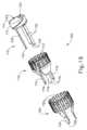
シャフトアセンブリ(16)とハンドルアセンブリ(11)との連結プロセスを開始するために、臨床医は、シャーシ(64)上に形成された先細取り付け部分(74)がフレーム(28)内のダブテールスロット(76)と位置合わせされるように、交換式シャフトアセンブリ(16)のシャーシ(64)をフレーム(28)の上方に又は隣接して位置決めすることができる。次いで、臨床医は、シャフトアセンブリ(16)を、シャフトアセンブリ(16)の長手方向軸に垂直な取り付け軸(IA)に沿って動かして、取り付け部分(74)を対応するダブテール受容スロット(76)と「動作可能に係合」させて収めてもよい。その際、中間発射シャフト(82)上のシャフト取り付けラグ(80)も、長手方向に移動可能な駆動部材(86)のクレードル(84)内に収められ、第2の閉鎖リンク(38)上にあるピン(42)の部分が、閉鎖シャトル(62)内の対応するフック(66)内に収められる。本明細書で使用するとき、2つの構成要素の文脈における「動作可能な係合」という用語は、それら2つの構成要素が互いに十分に係合され、そのため、作動運動をそれらに適用すると、構成要素が、意図される行為、機能及び/又は手順を実施し得ることを意味する。 To begin the coupling process between shaft assembly (16) and handle assembly (11), the clinician must ensure that tapered attachment portion (74) formed on chassis (64) is aligned with dovetail slot (28) in frame (28). 76), the chassis (64) of the replaceable shaft assembly (16) may be positioned above or adjacent to the frame (28). The clinician then moves shaft assembly (16) along an attachment axis (IA) perpendicular to the longitudinal axis of shaft assembly (16) to align attachment portion (74) with corresponding dovetail receiving slot (76). may be housed in "operable engagement" with the In doing so, the shaft mounting lug (80) on the intermediate firing shaft (82) is also received within the cradle (84) of the longitudinally movable drive member (86) and on the second closure link (38). A portion of a pin (42) is nested within a corresponding hook (66) within a closure shuttle (62). As used herein, the term "operable engagement" in the context of two components means that the two components are fully engaged with each other such that, upon application of actuation motion to them, the configuration It means that an element can perform the intended action, function and/or procedure.
上述のように、交換式シャフトアセンブリ(16)の少なくとも5つのシステムが、ハンドル(14)の少なくとも5つの対応するシステムと動作可能に連結され得る。第1のシステムは、シャフトアセンブリ(16)のフレーム又はスパインをハンドル(14)のフレーム(28)と連結及び/又は整合する、フレームシステムを備える。第2のシステムは、シャフトアセンブリ(16)をハンドル(14)に解放可能にロックするためのラッチシステムである。 As noted above, at least five systems of interchangeable shaft assemblies (16) may be operatively coupled with at least five corresponding systems of handles (14). The first system comprises a frame system that connects and/or aligns the frame or spine of shaft assembly (16) with frame (28) of handle (14). The second system is a latch system for releasably locking the shaft assembly (16) to the handle (14).
第3のシステムは、ハンドル(14)の閉鎖トリガ(32)、並びにシャフトアセンブリ(16)の閉鎖管(60)及びアンビル(50)を動作可能に接続し得る閉鎖駆動システム(30)である。上で概説したように、シャフトアセンブリ(16)の閉鎖シャトル(62)は、第2の閉鎖リンク(38)上にあるピン(42)と係合する。閉鎖駆動システム(30)を介して、アンビル(50)は、ピストルグリップ(26)に向かって及びピストルグリップから離れる方向への閉鎖トリガ(32)の枢動に基づいて、ステープルカートリッジ(20)に向かって及びステープルカートリッジ(20)から離れる方向に枢動する。 A third system is a closure drive system (30) that may operably connect the closure trigger (32) of the handle (14) and the closure tube (60) and anvil (50) of the shaft assembly (16). As outlined above, closure shuttle (62) of shaft assembly (16) engages pin (42) on second closure link (38). Via closure drive system (30), anvil (50) engages staple cartridge (20) upon pivotal movement of closure trigger (32) toward and away from pistol grip (26). Pivoting toward and away from the staple cartridge (20).
第4のシステムは、ハンドル(14)の発射トリガ(33)をシャフトアセンブリ(16)の中間発射シャフト(82)と動作可能に接続する関節運動及び発射駆動システムである。上で概説したように、シャフト取り付けラグ(80)は、長手方向駆動部材(86)のクレードル(84)と動作可能に接続する。この第4のシステムは、閉鎖トリガ(32)の枢動位置に応じて、関節ジョイント(52)又はステープルカートリッジ(20)のいずれかの電動作動を提供する。閉鎖トリガ(32)が非作動枢動位置にあるとき、第4のシステムは、関節ジョイント(52)と関節制御ロッカー(112)とを動作可能に接続し、それによって、関節ジョイント(52)においてシャフトアセンブリ(11)の長手方向軸に向かう及び長手方向軸から離れる方向へのエンドエフェクタ(18)の電動枢動偏向を提供する。閉鎖トリガ(32)が作動枢動位置にあるとき、第4のシステムは、発射トリガ(33)とステープルカートリッジ(20)とを動作可能に接続し、発射トリガ(33)の作動に応答してアンビル(50)とステープルカートリッジ(20)との間に捕捉された組織のステープル留め及び切断を実行させる。 The fourth system is an articulation and firing drive system that operably connects firing trigger (33) of handle (14) with intermediate firing shaft (82) of shaft assembly (16). As outlined above, the shaft mounting lug (80) operatively connects with the cradle (84) of the longitudinal drive member (86). This fourth system provides motorized actuation of either articulated joint (52) or staple cartridge (20) depending on the pivoted position of closure trigger (32). When closure trigger (32) is in the non-actuated pivot position, the fourth system operatively connects articulation joint (52) and articulation control rocker (112), thereby providing at articulation joint (52) Provides motorized pivotal deflection of the end effector (18) toward and away from the longitudinal axis of the shaft assembly (11). A fourth system operably connects the firing trigger (33) and the staple cartridge (20) when the closure trigger (32) is in the actuated pivot position, and responsive to actuation of the firing trigger (33) Causes stapling and cutting of tissue captured between anvil (50) and staple cartridge (20).
第5のシステムは、シャフトアセンブリ(16)がハンドル(14)と動作可能に係合されたことをハンドル(14)内の制御回路(117)に信号で伝えて、シャフトアセンブリ(16)とハンドル(14)との間で電気を通す、及び/又は信号を通信することができる電気システムである。本実施例では、図3に示すように、シャフトアセンブリ(16)は、シャフト回路基板(図示せず)に動作可能に載置された電気コネクタ(106)を含む。電気コネクタ(106)は、ハンドル制御基板(図示せず)上の対応する電気コネクタ(108)との噛合係合のために構成されている。回路及び制御システムに関する更なる詳細は、その開示内容が参照により本明細書に組み込まれる米国特許公開第2014/0263541号、及び/又はその開示内容が参照により本明細書に組み込まれる米国特許公開第2015/0272575号に見出すことができる。 A fifth system signals to control circuitry (117) in handle (14) that shaft assembly (16) is operatively engaged with handle (14), thereby disengaging shaft assembly (16) and handle (14). (14) is an electrical system capable of conducting electricity and/or communicating signals to and from. In the present example, as shown in FIG. 3, shaft assembly (16) includes an electrical connector (106) operably mounted to a shaft circuit board (not shown). Electrical connector (106) is configured for mating engagement with a corresponding electrical connector (108) on a handle control board (not shown). Further details regarding the circuit and control system can be found in US Patent Publication No. 2014/0263541, the disclosure of which is incorporated herein by reference, and/or US Patent Publication No. 2014/0263541, the disclosure of which is incorporated herein by reference. 2015/0272575.
上述したように、本実施例のハンドルアセンブリ(11)は、グラフィカルユーザインターフェース(116)を含む。単なる例として、グラフィカルユーザインターフェース(116)は、バッテリ(110)の動作状態、エンドエフェクタ(18)の動作状態、関節ジョイント(52)の動作状態、トリガ(32、33)の動作状態についての各種情報、及び/又は任意の他の種類の情報を表示するために使用されてもよい。グラフィカルユーザインターフェースを介して示され得るその他の好適な情報源は、本明細書の教示に鑑み、当業者に明らかになるであろう。 As noted above, handle assembly (11) of the present example includes a graphical user interface (116). By way of example only, the graphical user interface (116) provides various information about the operating state of the battery (110), the operating state of the end effector (18), the operating state of the articulating joint (52), the operating state of the triggers (32, 33). may be used to display information and/or any other type of information. Other suitable sources of information that can be presented via a graphical user interface will be apparent to those skilled in the art in view of the teachings herein.
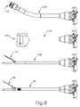
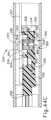
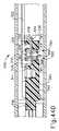
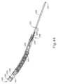
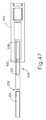
ハンドルアセンブリ(11)は、シャフトの長さ、サイズ、及び種類などが異なる様々なサイズ及び種類のステープルカートリッジを支持するように適合されたエンドエフェクタを含む交換式シャフトアセンブリに関連して使用するように構成され得る。単なる例として、図6は、ハンドルアセンブリ(11)と共に使用され得る各種シャフトアセンブリ(16、120、130、140)を示す。具体的には、図6は、円形ステープル留め動作(例えば、端々吻合)を実行するように動作可能なエンドエフェクタ(122)を有する円形ステープラシャフトアセンブリ(120)と、線形ステープル留め動作を実行するように動作可能なエンドエフェクタ(132)を有する線形ステープラシャフトアセンブリ(130)と、エンドエフェクタ(18)と同じ種類のステープル留め及び切断動作を行うように動作可能なエンドエフェクタ(142)を備える第2のエンドカッターシャフトアセンブリ(140)と、を示す。しかしながら、本実施例では、シャフトアセンブリ(140)はシャフトアセンブリ(16)よりも短く、シャフトアセンブリ(140)はシャフトアセンブリ(16)よりも直径が小さく、エンドエフェクタ(142)はエンドエフェクタ(18)よりも小さい。これらの様々な外科用ステープル留めシャフトアセンブリ(16、120、130、140)は、単なる例にすぎない。 The handle assembly (11) is adapted for use in conjunction with an interchangeable shaft assembly including end effectors adapted to support various sizes and types of staple cartridges, such as shaft lengths, sizes and types. can be configured to By way of example only, FIG. 6 shows various shaft assemblies (16, 120, 130, 140) that may be used with handle assembly (11). Specifically, FIG. 6 illustrates a circular stapler shaft assembly (120) having an end effector (122) operable to perform a circular stapling motion (e.g., an end-to-end anastomosis) and a linear stapling motion. and an end effector (142) operable to perform the same type of stapling and cutting action as end effector (18). 2 end cutter shaft assemblies (140). However, in the present example, shaft assembly (140) is shorter than shaft assembly (16), shaft assembly (140) is smaller in diameter than shaft assembly (16), and end effector (142) is shorter than end effector (18). less than These various surgical stapling shaft assemblies (16, 120, 130, 140) are merely examples.
また、制御回路(117)は、ハンドルアセンブリ(11)と連結されたシャフトアセンブリ(16、120、130、140)の種類を検出し、その特定の種類のシャフトアセンブリ(16、120、130、140)に適した制御アルゴリズムを選択するように構成され得ることを理解されたい。別の単なる例として、各シャフトアセンブリ(16、120、130、140)は、その特定の種類のシャフトアセンブリ(16、120、130、140)に適した制御アルゴリズムを記憶するチップ又は他のメモリデバイスを有してもよく、制御回路(117)は、シャフトアセンブリ(16、120、130、140)がハンドルアセンブリ(11)と連結された後に、その制御アルゴリズムを受信及び実行することができる。 Control circuit (117) also detects the type of shaft assembly (16, 120, 130, 140) coupled with handle assembly (11) and controls that particular type of shaft assembly (16, 120, 130, 140). ) can be configured to select a control algorithm suitable for As another example only, each shaft assembly (16, 120, 130, 140) may include a chip or other memory device that stores control algorithms suitable for that particular type of shaft assembly (16, 120, 130, 140). and control circuitry (117) can receive and execute its control algorithm after shaft assembly (16, 120, 130, 140) is coupled with handle assembly (11).
加えて、ハンドルアセンブリ(11)はまた、例えば、高周波(RF)エネルギー、超音波エネルギー及び/又は運動などのエネルギーの他の運動及び形態を、様々な外科用途及び処置に関連した使用のために適合されたエンドエフェクタ構成に適用するように構成されたアセンブリを含む、様々な他の交換式シャフトアセンブリと共に効果的に用いられてもよい。更に、エンドエフェクタ、シャフトアセンブリ、ハンドル、外科用器具及び/又は外科用器具システムは、任意の好適な締結具(複数可)を利用して組織を締結することができる。例えば、中に着脱可能に格納された複数の締結具を備える締結具カートリッジが、シャフトアセンブリのエンドエフェクタに着脱可能に挿入及び/又は装着され得る。そのようなカートリッジの様々な例は、本明細書に列挙される様々な参考文献に開示されている。 In addition, the handle assembly (11) may also transmit other motions and forms of energy, such as radio frequency (RF) energy, ultrasonic energy and/or motion, for use in connection with various surgical applications and procedures. It may be effectively used with a variety of other interchangeable shaft assemblies, including assemblies configured to accommodate matched end effector configurations. Additionally, end effectors, shaft assemblies, handles, surgical instruments and/or surgical instrument systems may utilize any suitable fastener(s) to fasten tissue. For example, a fastener cartridge comprising a plurality of fasteners removably stored therein may be removably inserted and/or attached to the end effector of the shaft assembly. Various examples of such cartridges are disclosed in the various references listed herein.
本明細書に開示される様々なシャフトアセンブリ(16)は、センサ、及び筐体(11)内の制御回路(117)との電気通信を必要とする他の様々な構成要素を用いてもよい。電気通信は、電気コネクタ(106、108)を嵌合することによって提供され得る。単なる例として、かかるセンサ及びその他の構成要素は、その開示内容が参照により本明細書に組み込まれる米国特許公開第2015/0272575号の教示の少なくともいくつかに従って構成され、かつ動作可能であってもよい。加えて又は代替的に、器具(10)は、本明細書に列挙される他の様々な参考文献のうちのいずれかの教示の少なくとも一部に従って構成され、かつ動作可能であってもよい。 The various shaft assemblies (16) disclosed herein may employ sensors and various other components that require electrical communication with the control circuitry (117) within the housing (11). . Electrical communication may be provided by mating electrical connectors (106, 108). Merely by way of example, such sensors and other components may be constructed and operable in accordance with at least some of the teachings of U.S. Patent Publication No. 2015/0272575, the disclosure of which is incorporated herein by reference. good. Additionally or alternatively, instrument (10) may be constructed and operable in accordance with, at least in part, the teachings of any of the various other references listed herein.
本明細書の様々な教示が、ロボット制御式外科用システムと接続して、効率よく利用され得ることもあると理解されよう。したがって、「筐体」又は「本体」という用語はまた、本明細書に開示される交換式シャフトアセンブリ及びそれらの対応する同等物を作動させるために使用され得る、少なくとも1つの制御運動を生成及び適用するように構成されている、少なくとも1つの駆動システムを収容する又はそれ以外の方法で動作可能に支持する、ロボットシステムの筐体、本体、又は同様の部分を包含してもよい。「フレーム」という用語は、手持ち式外科用器具の一部分を指してもよい。「フレーム」という用語はまた、ロボット制御式外科用器具の一部、及び/又は外科用器具を動作可能に制御するために使用され得るロボットシステムの一部を表してもよい。例えば、本明細書に開示される交換式シャフトアセンブリは、その開示内容が参照により本明細書に組み込まれる、2015年7月7日に発行された米国特許第9,072,535号の名称「Surgical Instruments with Rotatable Staple Deployment Arrangements」に開示された、様々なロボットシステム、器具、構成要素、及び方法のいずれかと共に用いられ得る。 It will be appreciated that the various teachings herein may also be effectively utilized in connection with robotic surgical systems. Accordingly, the terms "housing" or "body" also refer to generating and controlling at least one control motion that can be used to actuate the interchangeable shaft assemblies disclosed herein and their corresponding equivalents. It may include a housing, body, or similar portion of a robotic system that houses or otherwise operably supports at least one drive system that is configured to apply. The term "frame" may refer to a portion of a handheld surgical instrument. The term "frame" may also refer to a portion of a robotic surgical instrument and/or a robotic system that may be used to operatively control a surgical instrument. For example, the interchangeable shaft assemblies disclosed herein are described in U.S. Pat. No. 9,072,535, issued Jul. 7, 2015, entitled " Surgical Instruments with Rotatable Staple Deployment Arrangements,” which may be used with any of the various robotic systems, instruments, components, and methods disclosed.
II.独立したステープル留め及び切断機構を有する例示的な円形ステープラアタッチメント
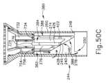
上述したように、ハンドルアセンブリ(11)は、円形ステープラシャフトアセンブリ(120)及びエンドエフェクタ(122)などの様々なエンドエフェクタを含む交換式シャフトアセンブリと関連して使用されて、端々吻合を形成するように構成されてもよい。例えば、いくつかの外科的処置(例えば、大腸外科手術、肥満外科手術、胸部外科手術等)では、望ましくない組織を除去するため、又はその他の理由によって、患者の消化管の一部(例えば、胃腸管及び/又は食道等)が除去される場合がある。組織が除去されると、消化管の残りの部分は、円形ステープラシャフトアセンブリ(120)及びエンドエフェクタ(122)のものと同様の円形ステープラを使用して、端々吻合で一緒に連結され得る。端々吻合により、吻合が行われた部位から、いかなる種類の漏れを生じることもなく、消化管の1つの部位から消化管の他の部位へ、実質的に遮るもののない流路が提供され得る。II. Exemplary Circular Stapler Attachment with Independent Stapling and Cutting Mechanisms As noted above, handle assembly (11) is interchangeable including various end effectors such as circular stapler shaft assembly (120) and end effector (122). It may be configured to be used in conjunction with a shaft assembly to form an end-to-end anastomosis. For example, in some surgical procedures (e.g., colon surgery, bariatric surgery, thoracic surgery, etc.), a portion of the patient's gastrointestinal tract (e.g., gastrointestinal tract and/or esophagus) may be removed. Once the tissue is removed, the remainder of the GI tract can be joined together in an end-to-end anastomosis using a circular stapler similar to that of circular stapler shaft assembly (120) and end effector (122). An end-to-end anastomosis may provide a substantially unobstructed flow path from one portion of the GI tract to another without leakage of any kind from the site where the anastomosis was performed.
例えば、円形ステープラは、組織の層を挟み、挟んだ組織層内へステープルを駆動し、挟んだ組織層を切断し、組織層の切断端部の近傍で組織を略封止することにより、解剖学的管腔の2つの切断端部を接合するように動作可能とすることができる。例えば、円形ステープラは、吻合においてステープルの環状アレイの内側にある余分な組織を切断して、吻合で接合される解剖学的管腔部分間の略滑らかな移行を提供することができる。 For example, a circular stapler clamps layers of tissue, drives staples into the clamped tissue layers, cuts the clamped tissue layers, and substantially seals the tissue near the cut ends of the tissue layers to effect dissection. It may be operable to join two cut ends of the surgical lumen. For example, a circular stapler can cut excess tissue inside an annular array of staples at an anastomosis to provide a substantially smooth transition between the anatomical lumen portions that are joined at the anastomosis.
場合によっては、円形ステープラを使用して端々吻合を形成するとき、ステープル形成及び吻合の一体性が不注意により悪影響を受けることがある。したがって、端々吻合中のステープル形成の不注意による悪影響を低減することが望ましい場合がある。更に、ステープル形成中に引き起こされる組織外傷の量を低減することが望ましい場合がある。 In some cases, when using a circular stapler to form an end-to-end anastomosis, the integrity of the staple formation and the anastomosis may be inadvertently adversely affected. Accordingly, it may be desirable to reduce the adverse effects of inadvertent staple formation during end-to-end anastomosis. Additionally, it may be desirable to reduce the amount of tissue trauma caused during staple formation.
例えば、ステープル形成は、余分な組織を切断しつつ、ステープルの環状列を組織内へと駆動することによって、悪影響を受ける可能性がある。例えば、第1列のステープルが余分な組織の切断と同時に形成されるとき、ステープルが完全に形成される前に、ステープル留めされた組織が余分な組織の切断から吸収された力により移動し始めることがある。第1列のステープルが完全に形成される前にステープル留めされた組織が移動すると、端々吻合の質に悪影響が及ぼされ得る。したがって、余分な組織の切断前に、第1列のステープルを組織内に発射することが望ましい場合がある。組織の切断前に第1列のステープルを組織内へ発射することで、ステープル形成完了前のステープル留めされた組織の不所望な移動を防止することができ、端々吻合におけるステープル形成の一体性を高めることができる。 For example, staple formation can be adversely affected by driving an annular row of staples into tissue while cutting excess tissue. For example, when the first row of staples is formed at the same time as the excess tissue is cut, the stapled tissue begins to move due to the force absorbed from the excess tissue cut before the staples are fully formed. Sometimes. Any movement of the stapled tissue before the first row of staples is fully formed can adversely affect the quality of the end-to-end anastomosis. Therefore, it may be desirable to fire the first row of staples into the tissue prior to cutting excess tissue. Firing the first row of staples into the tissue prior to tissue severing can prevent unwanted movement of the stapled tissue prior to completion of staple formation, thereby ensuring the integrity of staple formation in an end-to-end anastomosis. can be enhanced.
また、ステープル形成は、複数の環状ステープル列を同時に駆動して端々吻合を形成することによっても悪影響を受け得る。したがって、第1の環状ステープル列を組織内に発射し、次いで、余分な組織の切断前に、追加の環状列(複数可)のステープルを連続的に組織内に発射することが望ましい場合がある。あるいは、余分な組織の切断前に、第1の環状ステープル列を組織内に発射し、次いで、余分な組織を切断しながら、第2の環状ステープル列を組織内に発射することが望ましい場合がある。第2列のステープルを組織内に連続的に発射して、端々吻合のより微細な締め付けを行う間、第1列のステープルを組織内に発射して端々吻合の大まかな形状を形成することができる。 Staple formation can also be adversely affected by simultaneously driving multiple circular staple rows to form an end-to-end anastomosis. Accordingly, it may be desirable to fire a first annular row of staples into tissue and then fire additional annular row(s) of staples sequentially into tissue prior to cutting excess tissue. . Alternatively, it may be desirable to fire a first circular row of staples into the tissue prior to cutting the excess tissue, and then fire a second circular row of staples into the tissue while cutting the excess tissue. be. The first row of staples can be fired into the tissue to form the rough shape of the end-to-end anastomosis while the second row of staples can be fired sequentially into the tissue to provide a finer cinching of the end-to-end anastomosis. can.
したがって、ステープルの環状列を別個に発射する能力、及び/又はブレードアセンブリを別個に発射して余分な組織を切断する能力を備えた円形ステープラを有することが望ましい場合がある。 Accordingly, it may be desirable to have a circular stapler with the ability to separately fire annular rows of staples and/or separately fire blade assemblies to cut excess tissue.
図8及び9は、上述のシャフトアセンブリ(16)及びエンドエフェクタ(18)の代わりにハンドルアセンブリ(11)と容易に組み込まれ得る例示的な交換式円形ステープラアタッチメント(150)を示す。以下でより詳細に説明するように、ハンドルアセンブリ(11)及び交換式円形ステープラアタッチメント(150)が相互に連結されるように構成されることで、円形ステープラアタッチメント(150)は、複数のステープル列の環状アレイを別個に駆動することによってだけでなく、少なくとも第1のステープル列が形成された後に、余分な組織を別個に切断することによって、端々吻合を実行することができる。特に、上記の説明に従って、臨床医が、ハンドルアセンブリ(11)を介して交換式円形ステープラアタッチメント(150)の部分を選択的に制御して端々吻合を形成し得るように、第1の駆動システム(30)及び長手方向駆動部材(86)は、交換式円形ステープラアタッチメント(150)の対応する部分に様々な制御運動を生成及び適用するように構成されている。 Figures 8 and 9 show an exemplary interchangeable circular stapler attachment (150) that can be easily incorporated with the handle assembly (11) in place of the shaft assembly (16) and end effector (18) described above. As will be described in more detail below, the handle assembly (11) and the interchangeable circular stapler attachment (150) are configured to be interconnected such that the circular stapler attachment (150) comprises a plurality of staple rows. End-to-end anastomosis can be performed not only by separately actuating the annular array of but also by separately cutting excess tissue after at least the first row of staples has been formed. Specifically, in accordance with the description above, a first drive system is provided so that a clinician can selectively control portions of interchangeable circular stapler attachment (150) via handle assembly (11) to form an end-to-end anastomosis. (30) and longitudinal drive member (86) are configured to generate and apply various controlled motions to corresponding portions of interchangeable circular stapler attachment (150).
交換式円形ステープラアタッチメント(150)は、シャフトアセンブリ(156)及びエンドエフェクタ(158)を含む。シャフトアセンブリ(156)は、近位筐体(210)、外側シース(240)、遠位筐体(260)、中間発射シャフト(226)、外側シース(240)及び遠位筐体(260)内に摺動可能に収容された往復駆動アセンブリ(400)、並びに往復駆動アセンブリ(400)内に摺動可能に収容されたトロカールアセンブリ(300)を含む。エンドエフェクタ(158)は、アンビル(600)、遠位筐体(260)の遠位端に固定されたデッキ部材(640)、デッキ部材(640)内に収容された複数のステープル(702)、並びに遠位筐体(260)内に摺動可能に収容されたステープル留め及び切断アセンブリ(700)を含む。以下でより詳細に説明するように、ハンドルアセンブリ(11)と適切に連結されると、トロカールアセンブリ(300)は、アンビル(600)と連結し、アンビルをデッキ部材(640)に向かって作動させて2つの組織層を圧縮するように構成されている。以下で更に詳細に説明するように、往復駆動アセンブリ(400)は、ステープル留め及び切断アセンブリ(700)の各部分を順次駆動して、ステープル(702)の複数の環状アレイを組織内に駆動し、次いで、組織の余分な部分を切断して、端々吻合を形成するように構成されている。 Interchangeable circular stapler attachment (150) includes a shaft assembly (156) and an end effector (158). Shaft assembly (156) includes proximal housing (210), outer sheath (240), distal housing (260), intermediate firing shaft (226), outer sheath (240) and within distal housing (260). and a trocar assembly (300) slidably received within the reciprocating drive assembly (400). End effector (158) includes an anvil (600), a deck member (640) secured to the distal end of distal housing (260), a plurality of staples (702) contained within deck member (640), and a stapling and cutting assembly (700) slidably housed within the distal housing (260). As will be described in more detail below, when properly coupled with handle assembly (11), trocar assembly (300) couples with anvil (600) and actuates the anvil toward deck member (640). configured to compress the two tissue layers. As will be described in more detail below, reciprocating drive assembly (400) sequentially drives portions of stapling and cutting assembly (700) to drive multiple annular arrays of staples (702) into tissue. and then cutting excess tissue to form an end-to-end anastomosis.
A.例示的なエンドエフェクタ
上述したように、エンドエフェクタ(158)は、アンビル(600)、デッキ部材(640)、並びにステープル留め及び切断アセンブリ(700)を含む。図10で最も良く分かるように、本実施例のアンビル(600)は、ヘッド(602)とシャンク(614)とを備えている。ヘッド(602)は、ステープル成形ポケット(606)の外側環状アレイと、ステープル成形ポケット(608)の内側環状アレイと、を画定する近位面(604)を含む。ステープル成形ポケット(606、608)は、ステープル(702)がステープル成形ポケット(606、608)内に駆動されるにつれてステープル(702)を変形させるように構成されている。例えば、各ステープル成形ポケット(606、608)は、当該技術分野において既知のように、略U字状のステープル(702)を「B」字状に変形し得る。近位面(604)は、シャンク(614)の周りを囲む環状凹部(612)の外側境界線を画定する内縁部で終端する。以下でより詳細に説明するように、ステープル成形ポケット(606)の外側環状アレイが、ステープル留め及び切断アセンブリ(700)の選択部分からステープル(702)を受容するように構成される一方、ステープル成形ポケット(608)の内側環状アレイは、ステープル留め及び切断アセンブリ(700)の別個の選択部分からステープル(702)を受容するように構成されている。A. Exemplary End Effector As noted above, end effector (158) includes anvil (600), deck member (640), and stapling and cutting assembly (700). As best seen in FIG. 10, anvil (600) of the present example includes a head (602) and a shank (614). Head (602) includes a proximal face (604) that defines an outer annular array of staple forming pockets (606) and an inner annular array of staple forming pockets (608). Staple forming pockets (606, 608) are configured to deform staples (702) as staples (702) are driven into staple forming pockets (606, 608). For example, each staple forming pocket (606, 608) may transform a generally U-shaped staple (702) into a "B" shape, as is known in the art. Proximal face (604) terminates at an inner edge that defines the outer boundary of an annular recess (612) that circumscribes shank (614). As will be described in more detail below, the outer annular array of staple forming pockets (606) is configured to receive staples (702) from selected portions of stapling and cutting assembly (700), while the staple forming An inner annular array of pockets (608) is configured to receive staples (702) from separate select portions of stapling and cutting assembly (700).
シャンク(614)は、穴(616)と一対の側方スロット(618)とを画定する。穴(616)は、シャンク(614)の近位端で開放して、トロカールアセンブリ(300)の遠位端を受容する。シャンク(614)は、トロカールアセンブリ(300)の一部がシャンク(614)内に挿入されるとき、アンビル(600)がエンドエフェクタ(158)の残りの部分及びシャフトアセンブリ(156)対してトロカールアセンブリ(300)と共に移動し得るように、トロカールアセンブリ(300)の遠位端と選択的に連結するように構成されている。換言すれば、適切に連結されると、トロカールアセンブリ(300)は、アンビル(600)をエンドエフェクタ(158)の残りの部分に向かって、及び残りの部分から離れるように駆動して、近位面(604)とデッキ部材(640)との間で組織を圧縮及び解放することができる。シャンク(614)は、本明細書の教示に鑑み当業者に明らかになるように、アンビル(600)をトロカールアセンブリ(300)と連結するための任意の好適な機構を含んでもよい。例えば、シャンク(614)は、シャンク(616)によって画定される長手方向軸から半径方向外向きに偏向してトロカールアセンブリ(300)とスナップ嵌めする、穴(616)内に配置された一対のラッチ部材(図示せず)を含んでもよい。 Shank (614) defines a bore (616) and a pair of lateral slots (618). Hole (616) opens at the proximal end of shank (614) to receive the distal end of trocar assembly (300). Shank (614) allows anvil (600) to engage trocar assembly (614) against the remainder of end effector (158) and shaft assembly (156) when portion of trocar assembly (300) is inserted into shank (614). It is configured to selectively couple with the distal end of trocar assembly (300) for movement therewith. In other words, when properly coupled, trocar assembly (300) drives anvil (600) toward and away from the rest of end effector (158) to provide proximal movement. Tissue may be compressed and released between surface (604) and deck member (640). Shank (614) may include any suitable mechanism for coupling anvil (600) with trocar assembly (300), as would be apparent to one of ordinary skill in the art in view of the teachings herein. For example, shank (614) is biased radially outwardly from a longitudinal axis defined by shank (616) to snap fit with trocar assembly (300) with a pair of latches disposed within holes (616). A member (not shown) may be included.
図13~15で最も良く分かるように、デッキ部材(640)は、遠位に提示されるデッキ面(642)と、複数の組織把持突出部(648)とを含む。デッキ部材(640)はまた、内径(646)、ステープル開口部(606)の外側同心環状アレイ、及びステープル留め開口部(645)の内側同心環状アレイを画定する。デッキ部材(640)は、遠位筐体(260)の遠位端に固定される。更に、デッキ部材(640)は、ステープル開口部(644、645)の両方に複数のステープル(702)を収容する。ステープル開口部(644、645)は、アンビル(600)とデッキ部材(640)が近位面(604)と遠位に提示されるデッキ面(642)との間で組織を圧縮するとき、ステープル成形ポケット(606、608)と位置合わせするように構成される。以下でより詳細に説明するように、ステープル開口部(644、645)は、ステープル及び切断アセンブリ(700)の対応する部分を受容して、ステープル(702)を対応するステープル成形ポケット(606、608)内に駆動するように構成される。 As best seen in FIGS. 13-15, deck member (640) includes a distally-presented deck surface (642) and a plurality of tissue-grasping projections (648). Deck member (640) also defines an inner diameter (646), an outer concentric annular array of staple openings (606), and an inner concentric annular array of stapling openings (645). Deck member (640) is secured to the distal end of distal housing (260). Further, deck member (640) houses a plurality of staples (702) in both staple openings (644, 645). Staple openings (644, 645) provide staple openings (644, 645) as anvil (600) and deck member (640) compress tissue between proximal surface (604) and distally presented deck surface (642). Configured to align with molded pockets (606, 608). As will be described in more detail below, staple openings (644, 645) receive staples and corresponding portions of cutting assembly (700) to insert staples (702) into corresponding staple forming pockets (606, 608). ).
図11で最も良く分かり、以下でより詳細に説明されるように、内径(646)は、ブレード部材(712)が内径(646)の領域内の余分な組織を切断し得るように、ステープル留め及び切断アセンブリ(700)のブレード部材(712)を受容する寸法決めされる。更に、内径(646)は、アンビル(600)がトロカールアセンブリ(300)と連結することができるように、トロカールアセンブリ(300)の選択部分を受容してもよい。 As best seen in FIG. 11 and described in more detail below, inner diameter (646) provides a stapling force such that blade member (712) can cut excess tissue within the region of inner diameter (646). and sized to receive blade member (712) of cutting assembly (700). Additionally, inner diameter (646) may receive selected portions of trocar assembly (300) such that anvil (600) may couple with trocar assembly (300).
図16で最も良く分かるように、ステープル留め及び切断アセンブリ(700)は、ブレードアセンブリ(710)、外側ステープルドライバ(750)、及び内側ステープルドライバアセンブリ(770)を含み、これらの全ては、シャフトアセンブリ(156)の遠位筐体(260)内に摺動可能に収容される。以下でより詳細に説明するように、ブレードアセンブリ(710)、外側ステープルドライバ(750)、及び内側ステープルドライバアセンブリ(770)は、ステープル(702)の環状アレイを駆動する、又は余分な組織を切断するように、デッキ部材(640)に対して個別に作動されるように構成される。 As best seen in FIG. 16, the stapling and cutting assembly (700) includes a blade assembly (710), an outer staple driver (750), and an inner staple driver assembly (770), all of which are shaft assemblies. (156) is slidably received within distal housing (260). As described in more detail below, blade assembly (710), outer staple driver (750), and inner staple driver assembly (770) drive an annular array of staples (702) or cut excess tissue. It is configured to be individually actuated relative to deck member (640) so as to do so.
図17で最も良く分かるように、外側ステープルドライバ(750)は、ステープルドライバの環状アレイ(752)と、それぞれが駆動カプラ(756)内で終端する3つの近位に提示される発射脚部(754)と、を含む。外側ステープルドライバ(750)は、内側ステープルドライバアセンブリ(770)を摺動可能に収容するように寸法決めされた穴(758)を画定する。ステープルドライバ(752)はそれぞれ、ステープル開口部(644)の外側同心環状アレイの各自のステープル開口部内で作動して、ステープル成形ポケットの外側環状アレイ(606)からステープル(702)を対応するステープル成形ポケットに対して駆動するように寸法決めされる。以下でより詳細に説明するように、近位に提示される発射脚部(754)及び各自の駆動カプラ(756)は、往復駆動アセンブリ(400)の一部と選択的に位置合わせされるように位置付けられるため、ステープルドライバ(752)は、ブレードアセンブリ(710)及び内側ステープルドライバアセンブリ(770)の両方から独立してステープル(702)を駆動することができる。 As best seen in FIG. 17, the outer staple driver (750) comprises an annular array (752) of staple drivers and three proximally presented firing legs (752) each terminating in a drive coupler (756). 754) and Outer staple driver (750) defines a hole (758) sized to slidably receive inner staple driver assembly (770). Staple drivers (752) each operate within a respective staple opening of the outer concentric annular array of staple openings (644) to drive staples (702) from the outer annular array (606) of staple forming pockets into corresponding staple formations. Dimensioned to drive against the pocket. As will be described in more detail below, proximally-presented firing legs (754) and respective drive couplers (756) are selectively aligned with a portion of reciprocating drive assembly (400). , staple driver (752) can drive staples (702) independently of both blade assembly (710) and inner staple driver assembly (770).
図18及び19で最も良く分かるように、内側ステープルドライバアセンブリ(770)は、複数の内側ステープルドライバ(780)を含み、各内側ステープルドライバは、外側ステープルドライバ(750)の発射脚部(754)によって画定される対応セクタ間に摺動可能に収容されるように構成されている。内側ステープル駆動部(780)は共に、ブレードアセンブリ(710)のブレード部材(712)を摺動可能に収容するように寸法決めされた穴(778)を画定する。各内側ステープル駆動部(780)は、外側ステープルドライバ(750)の穴(758)内に位置する。各内側ステープル駆動部(780)は、ステープル成形ポケット(608)の内側環状アレイに対してステープル(702)を駆動するために、ステープル開口部(645)の内側同心環状アレイの対応するステープル開口部内で作動するように寸法決めされた複数のステープルドライバ(772)を含む。更に、各内側ステープル駆動部(780)は、駆動カプラ(776)を有する、近位に提示される発射脚部(774)を含む。以下でより詳細に説明するように、近位に提示される発射脚部(754)及び各自の駆動カプラ(776)は、往復駆動アセンブリ(400)の一部と選択的に位置合わせされるように位置付けられるため、各内側ステープルドライバ部分(780)のステープルドライバ(772)は、ブレードアセンブリ(710)及び内側ステープルドライバアセンブリ(770)の両方から独立してステープル(702)を駆動することができる。 As best seen in FIGS. 18 and 19, inner staple driver assembly (770) includes a plurality of inner staple drivers (780), each inner staple driver corresponding to a firing leg (754) of outer staple driver (750). is configured to be slidably received between corresponding sectors defined by Together, inner staple drivers (780) define holes (778) sized to slidably receive blade members (712) of blade assembly (710). Each inner staple driver (780) is located within a bore (758) of outer staple driver (750). Each inner staple driver (780) is positioned within a corresponding staple opening of the inner concentric annular array of staple openings (645) to drive the staples (702) against the inner annular array of staple forming pockets (608). a plurality of staple drivers (772) sized to operate at In addition, each inner staple driver (780) includes a proximally presented firing leg (774) having a drive coupler (776). As will be described in more detail below, proximally-presented firing legs (754) and respective drive couplers (776) are selectively aligned with a portion of reciprocating drive assembly (400). so that staple drivers (772) of each inner staple driver portion (780) can drive staples (702) independently from both blade assembly (710) and inner staple driver assembly (770). .
図20及び図21で最も良く分かるように、ブレードアセンブリ(710)は、円筒形ブレード部材(712)と、連結リング(730)と、を含む。円筒形ブレード部材(712)は、遠位切断縁部(714)、近位に提示される面(716)、及びフランジ(718)を含む。円筒形ブレード部材(712)はまた、内側コア経路(720)、組織空隙筐体(722)、回転カムスロット(724)を画定する。以下により詳細に記載されるように、内側コア経路(720)は、遠位筐体(260)の内側コア(262)を受容するようにサイズ決めされ、組織空隙筐体(722)は、切断された組織を受容するように寸法決めされる。回転カムスロット(724)は、円筒形ブレード部材(712)が作動されるときに円筒形ブレード部材(712)が回転するように、遠位筐体(260)の内側コア(262)上のらせん状ブレードカム(280)と嵌合するように構成されている。近位に提示される面(716)及びフランジ(718)は、連結リング(730)と回転可能に連結するように構成されており、ブレードアセンブリ(710)の作動中、円筒形ブレード部材(712)が連結リング(730)に対して回転することができる。 As best seen in FIGS. 20 and 21, blade assembly (710) includes a cylindrical blade member (712) and a connecting ring (730). Cylindrical blade member (712) includes a distal cutting edge (714), a proximally presented surface (716), and a flange (718). Cylindrical blade member (712) also defines an inner core passageway (720), a tissue void enclosure (722), and a rotating cam slot (724). As described in more detail below, inner core passageway (720) is sized to receive inner core (262) of distal housing (260), and tissue void housing (722) provides a cutting sized to receive the tissue to be treated. Rotation cam slot (724) is helical on inner core (262) of distal housing (260) such that cylindrical blade member (712) rotates when cylindrical blade member (712) is actuated. configured to mate with a shaped blade cam (280). Proximally-presented surface (716) and flange (718) are configured to rotatably couple with coupling ring (730) such that during actuation of blade assembly (710), cylindrical blade member (712) ) can rotate relative to the coupling ring (730).
連結リング(730)は、それぞれが駆動カプラ(734)内で終端する3つの近位に提示される発射脚部(732)を含む。以下により詳細に記載されるように、近位に提示される発射脚部(732)及び対応する駆動カプラ(734)は、往復駆動体アセンブリ(400)の一部と選択的に位置合わせされるように位置付けられるため、かかる円筒形ブレード部材(712)は、外側ステープルドライバ(750)及び内側ステープルドライバアセンブリ(770)から独立して余分な組織を切断することができる。 Coupling ring (730) includes three proximally-presented firing legs (732) that each terminate in drive couplers (734). A proximally-presented firing leg (732) and corresponding drive coupler (734) are selectively aligned with a portion of reciprocating driver assembly (400), as described in more detail below. Positioned such that such cylindrical blade member (712) can cut excess tissue independently of outer staple driver (750) and inner staple driver assembly (770).
B.シャフトアセンブリの例示的な近位筐体
以下により詳細に記載されるように、近位筐体(210)の選択部分は、動作可能な係合のためにハンドルアセンブリ(11)の選択部分と連結するように構成される。近位筐体(210)は、上述のノズル部分(56、58)と略同様である一対のノズル部分(212、214)を含み、以下に相違点を説明する。B. Exemplary Proximal Housing of Shaft Assembly As described in more detail below, selected portions of the proximal housing (210) are coupled for operable engagement with selected portions of the handle assembly (11). configured to Proximal housing (210) includes a pair of nozzle portions (212, 214) that are substantially similar to nozzle portions (56, 58) described above, with the differences noted below.
近位筐体(210)は、並進シャトル(216)と、ノズル部分(212、214)内に収容されたシャーシ(218)と、を含む。上述の閉鎖シャトル(62)と同様、並進シャトル(216)は、第2の閉鎖リンク(38)に取り付けられた取り付けピン(42)への取り付けのために構成されている、一対の近位突出フック(220)を含む。したがって、適切に連結されると、並進シャトル(216)は、上記の説明に従って、非作動枢動位置(図4Aに示す)と作動枢動位置(図4Bに示す)との間で移動する閉鎖トリガ(32)に応答して、シャーシ(218)に対して並進するように構成されている。以下でより詳細に説明するように、並進シャトル(216)が作動すると、クラッチアセンブリ(500)が作動し、中間発射シャフト(226)からトロカールアセンブリ(300)を選択的に連結及び分離するように構成されている。 Proximal housing (210) includes a translation shuttle (216) and a chassis (218) housed within nozzle portions (212, 214). Similar to closure shuttle (62) described above, translation shuttle (216) has a pair of proximal projections configured for attachment to mounting pins (42) attached to second closure link (38). Includes hook (220). Thus, when properly coupled, translational shuttle (216) moves between a non-actuated pivot position (shown in FIG. 4A) and an actuated pivot position (shown in FIG. 4B) in accordance with the description above. It is configured to translate relative to chassis (218) in response to trigger (32). As will be described in more detail below, actuation of translation shuttle (216) actuates clutch assembly (500) to selectively connect and disconnect trocar assembly (300) from intermediate firing shaft (226). It is configured.
上述のシャーシ(64)と同様、シャーシ(218)は、フレーム(28)の遠位取り付けフランジ部分(78)に形成された対応するダブテールスロット(76)内に受容されるように適合された一対の先細取り付け部分(222)を含む。各ダブテールスロット(76)は、取り付け部分(222)を着座させ受容するように、先細であってもよい、又は略V字形であってもよい。取り付け部分(222)がダブテールスロット(76)内に適切に配置されると、シャーシ(218)は、ハンドルアセンブリ(11)のフレーム(28)に長手方向及び回転可能に固定される。 Similar to chassis (64) described above, chassis (218) is a pair adapted to be received within corresponding dovetail slots (76) formed in distal mounting flange portion (78) of frame (28). tapered attachment portion (222). Each dovetail slot (76) may be tapered or generally V-shaped to seat and receive a mounting portion (222). When mounting portion (222) is properly positioned within dovetail slot (76), chassis (218) is longitudinally and rotatably secured to frame (28) of handle assembly (11).
また、近位筐体(210)は、近位筐体(210)をハンドルアセンブリ(11)、より具体的には、フレーム(28)に着脱可能に連結するためのラッチシステムを含む。換言すれば、取り付け部分(222)が、フレーム(28)に対するシャーシ(218)の長手方向及び回転移動を防止する間、ラッチシステムは、シャーシ(218)が適切に連結されたときにダブテールスロット(76)から垂直に滑り出るのを防止することができる。 Proximal housing (210) also includes a latch system for detachably coupling proximal housing (210) to handle assembly (11), and more specifically frame (28). In other words, while attachment portion (222) prevents longitudinal and rotational movement of chassis (218) with respect to frame (28), latch system provides a dovetail slot (222) when chassis (218) is properly coupled. 76) can be prevented from sliding out vertically.
単なる例として、このラッチシステムは、シャーシ(218)に移動可能に連結されたロックヨーク又は他の種類のロック部材を含んでもよい。図9及び28に示されるように、かかるロックヨークは、フレーム(28)内の対応するロック戻り止め又は溝(98)と解除可能に係合するように構成された2つの近位突出ロックラグ(228)を含んでもよい。ロックヨークの作動は、シャーシ(218)に摺動可能に取り付けられると共に、ロックラグ(228)にも取り付けられるラッチボタン(230)によって達成され得る。図28で最も良く分かるように、ラッチボタン(230)及びロックラグ(228)は、ロックラグ(228)が枢動点(231)を中心に近位ロック位置に向かってシャーシ(218)に対して枢動されるように、付勢ばね(229)を介して近位に付勢される。ロックヨークは、ラッチボタン(100)を遠位方向に付勢することによってロック解除位置へ移動されてもよく、またこれにより、ロックヨークが枢動して、フレーム(28)との保持係合から外れる。ロックヨークがフレーム(28)と「保持係合」しているとき、ロックラグ(228)は、対応するロック戻り止め又は溝(98)内に保持的に着座される。単に更なる例として、近位筐体(210)は、その開示内容が参照により本明細書に組み込まれる米国特許公開第2017/0086823号の教示の少なくとも一部、その開示内容が参照により本明細書に組み込まれる米国特許公開第2015/0280384号の教示の少なくとも一部、及び/又は任意のその他の適切な様式に応じて、ハンドルアセンブリ(11)に取り外し可能に連結することができる。 By way of example only, this latch system may include a locking yoke or other type of locking member movably coupled to chassis (218). As shown in FIGS. 9 and 28, such locking yoke includes two proximally projecting locking lugs (see FIG. 9 and 28) configured to releasably engage corresponding locking detents or grooves (98) in frame (28). 228). Actuation of the lock yoke may be accomplished by a latch button (230) slidably attached to chassis (218) and also attached to lock lug (228). As best seen in FIG. 28, latch button (230) and locking lug (228) are arranged such that locking lug (228) pivots relative to chassis (218) toward a proximal locked position about pivot point (231). As it is moved, it is biased proximally via a biasing spring (229). The locking yoke may be moved to the unlocked position by biasing latch button (100) distally, which also pivots the locking yoke into retaining engagement with frame (28). deviate from When the locking yoke is in "retaining engagement" with the frame (28), the locking lugs (228) are retainingly seated within corresponding locking detents or grooves (98). Merely as a further example, the proximal housing (210) is at least partially taught in U.S. Patent Publication No. 2017/0086823, the disclosure of which is incorporated herein by reference. It can be removably coupled to the handle assembly (11) in accordance with at least some of the teachings of US Patent Publication No. 2015/0280384 incorporated herein, and/or in any other suitable manner.
シャーシ(218)は、上記の電気コネクタ(106)と略同様であり得る電気コネクタ(232)を更に含む。したがって、電気コネクタ(232)は、シャフト回路基板(図示せず)に動作可能に装着されてもよい。電気コネクタ(232)は、ハンドル制御基板(図示せず)上の対応する電気コネクタ(108)との噛合係合のために構成されている。回路及び制御システムに関する更なる詳細は、その開示内容を参照により本明細書に組み込まれる米国特許公開第2014/0263541号、及び/又はその開示内容が参照により本明細書に組み込まれる米国特許公開第2015/0272575号に見出し得る。 Chassis (218) further includes an electrical connector (232) that may be substantially similar to electrical connector (106) described above. Thus, electrical connector (232) may be operatively attached to a shaft circuit board (not shown). Electrical connector (232) is configured for mating engagement with a corresponding electrical connector (108) on a handle control board (not shown). Further details regarding the circuit and control system can be found in US Patent Publication No. 2014/0263541, the disclosure of which is incorporated herein by reference, and/or US Patent Publication No. 2014/0263541, the disclosure of which is incorporated herein by reference. 2015/0272575.
上述したように、シャフトアセンブリ(156)は、シャフト取り付けラグ(224)を有する中間発射シャフト(226)を更に備え、中間発射シャフト(226)は、上述のシャフト取り付けラグ(80)を有する中間発射シャフト(82)と略同様であり、相違点を以下に説明する。シャフト取り付けラグ(224)は、シャフトアセンブリ(156)がハンドルアセンブリ(11)と適切に連結されたときに、長手方向可動駆動部材(86)のクレードル(84)に着座するように構成される。以下でより詳細に説明するように、モータ(118)は、本明細書の説明に従って、中間発射シャフト(226)を駆動して、トロカールアセンブリ(300)及び往復駆動アセンブリ(400)を作動させるように動作可能である。 As noted above, shaft assembly (156) further comprises an intermediate firing shaft (226) having shaft mounting lugs (224), which intermediate firing shaft (226) has shaft mounting lugs (80) as described above. It is substantially similar to shaft (82), with differences noted below. Shaft mounting lug (224) is configured to seat in cradle (84) of longitudinally movable drive member (86) when shaft assembly (156) is properly coupled with handle assembly (11). As described in more detail below, motor (118) drives intermediate firing shaft (226) to operate trocar assembly (300) and reciprocating drive assembly (400) in accordance with the description herein. is operable.
シャフトアセンブリ(156)の近位筐体(210)とハンドルアセンブリ(11)との連結プロセスを開始するために、臨床医は、シャーシ(218)上に形成された先細取り付け部分(222)がフレーム(28)内のダブテールスロット(76)と位置合わせされるように、近位筐体(210)のシャーシ(218)をフレーム(28)の上方に又は隣接して位置決めすることができる。次いで、臨床医は、シャフトアセンブリ(156)を、中間発射シャフト(226)の長手方向軸に垂直な取り付け軸(IA)に沿って動かして、取り付け部分(222)を対応するダブテール受容スロット(76)と「動作可能に係合」させて着座させてもよい。その際、中間発射シャフト(226)上のシャフト取り付けラグ(224)も、長手方向に移動可能な駆動部材(86)のクレードル(84)内に着座し、第2の閉鎖リンク(38)上にあるピン(42)の部分が、並進シャトル(216)内の対応するフック(220)内に着座する。 To begin the process of coupling proximal housing (210) of shaft assembly (156) and handle assembly (11), the clinician will assemble tapered attachment portion (222) formed on chassis (218) into the frame. Chassis (218) of proximal housing (210) may be positioned above or adjacent frame (28) so as to align with dovetail slot (76) in (28). The clinician then moves shaft assembly (156) along an attachment axis (IA) perpendicular to the longitudinal axis of intermediate firing shaft (226) to align attachment portion (222) with corresponding dovetail receiving slot (76). ) may be seated in "operable engagement" with. In so doing, the shaft mounting lug (224) on the intermediate firing shaft (226) also seats within the cradle (84) of the longitudinally movable drive member (86) and overlies the second closure link (38). A portion of one pin (42) seats within a corresponding hook (220) in translation shuttle (216).
適切に連結されたときのノズル部分(212、214)は、並進シャトル(216)、シャーシ(218)、ロックラグ(228)、付勢ばね(229)、電気コネクタ(332)、及びラッチボタン(230)を除いて、エンドエフェクタ(158)及びシャフトアセンブリ(156)の選択部分を回転させるように動作可能である。具体的には、ノズル部分(212、214)は、外側シース(240)によって画定される長手方向軸を中心に、エンドエフェクタ(158)及びシャフトアセンブリ(156)の選択部分を回転させることができる。したがって、臨床医は、エンドエフェクタ(158)及びシャフトアセンブリ(156)を、端々吻合処置に備えて所望の回転配向まで回転させることができる。 The nozzle portions (212, 214) when properly coupled comprise a translation shuttle (216), a chassis (218), a locking lug (228), a biasing spring (229), an electrical connector (332), and a latch button (230). ), are operable to rotate selected portions of end effector (158) and shaft assembly (156). Specifically, nozzle portions (212, 214) can rotate selected portions of end effector (158) and shaft assembly (156) about a longitudinal axis defined by outer sheath (240). . Accordingly, a clinician can rotate end effector (158) and shaft assembly (156) to a desired rotational orientation in preparation for an end-to-end anastomosis procedure.
上述したシャフトアセンブリ(16)と同様、交換式円形ステープラアタッチメント(150)の少なくとも5つのシステムが、ハンドル(14)の少なくとも5つの対応するシステムと動作可能に連結され得る。上述したように、第1のシステムは、シャフトアセンブリ(156)のフレーム又はスパインをハンドル(14)のフレーム(28)と連結する及び/又は位置合わせする、フレームシステムを備える。上述したように、第2のシステムは、シャフトアセンブリ(156)をハンドル(14)に解放可能にロックするラッチシステムである。 Similar to shaft assembly (16) described above, at least five systems of interchangeable circular stapler attachments (150) may be operatively coupled with at least five corresponding systems of handle (14). As noted above, the first system comprises a frame system that connects and/or aligns the frame or spine of shaft assembly (156) with frame (28) of handle (14). As noted above, the second system is a latch system that releasably locks shaft assembly (156) to handle (14).
第3のシステムは、ハンドル(14)の閉鎖トリガ(32)と近位筐体(210)の並進シャトル(216)を動作可能に接続し得る第1の駆動システム(30)である。上述したように、かつ後述するように、第3のシステムは、クラッチアセンブリ(500)を作動させて、中間発射シャフト(226)からトロカールアセンブリ(300)を選択的に連結及び分離するために使用されてもよい。 A third system is a first drive system (30) that may operably connect the closure trigger (32) of the handle (14) and the translational shuttle (216) of the proximal housing (210). As described above and as described below, the third system is used to actuate clutch assembly (500) to selectively connect and disconnect trocar assembly (300) from intermediate firing shaft (226). may be
第4のシステムは、ハンドル(14)の制御ロッカー(112)及び発射トリガ(33)を、シャフトアセンブリ(156)の中間発射シャフト(226)と動作可能に接続する、トロカール及び発射駆動システムである。上で概説したように、シャフト取り付けラグ(224)は、長手方向駆動部材(86)のクレードル(84)と動作可能に接続する。この第4のシステムは、閉鎖トリガ(32)の枢動位置に応じて、トロカールアセンブリ(300)又は往復駆動部材(400)のいずれかの電動作動を提供する。以下でより詳細に説明するように、閉鎖トリガ(32)が非作動枢動位置にあるとき(図4Aに示す)、第4のシステムは、制御ロッカー(112)をトロカールアセンブリ(300)と動作可能に接続し、それによってトロカールアセンブリ(300)の電動作動を提供する。閉鎖トリガ(32)が作動枢動位置にあるとき(図4Bに示す)、第4システムは、往復駆動アセンブリ(400)と発射トリガ(33)とを動作可能に接続し、発射トリガ(33)の作動に応答して、アンビル(600)とデッキ部材(640)との間に捕捉された組織の連続的なステープル留め及び切断を実行させる。 The fourth system is a trocar and firing drive system that operably connects control rocker (112) and firing trigger (33) of handle (14) with intermediate firing shaft (226) of shaft assembly (156). . As outlined above, shaft mounting lug (224) operatively connects with cradle (84) of longitudinal drive member (86). This fourth system provides motorized actuation of either the trocar assembly (300) or the reciprocating drive member (400) depending on the pivoted position of the closure trigger (32). As will be described in more detail below, the fourth system operates control rocker (112) with trocar assembly (300) when closure trigger (32) is in the non-actuated pivot position (shown in FIG. 4A). operably connect thereby providing motorized actuation of the trocar assembly (300). When closure trigger (32) is in the actuated pivot position (shown in FIG. 4B), the fourth system operatively connects reciprocating drive assembly (400) and firing trigger (33), causing firing trigger (33) to , causing continuous stapling and severing of tissue captured between anvil (600) and deck member (640).
第5のシステムは、シャフトアセンブリ(156)がハンドル(14)と動作可能に係合されたことをハンドル(14)内の制御回路に信号で伝えて、シャフトアセンブリ(156)とハンドル(14)との間で電気を通す、及び/又は信号を通信することができる電気システムである。 A fifth system signals control circuitry within handle (14) that shaft assembly (156) has been operably engaged with handle (14), thereby coupling shaft assembly (156) and handle (14). An electrical system capable of conducting electricity and/or communicating signals between
ハンドル(14)の対応システムと動作可能に連結され得る他の種類の交換式シャフトアセンブリ(156)のシステムは、本明細書の教示に鑑み、当業者には明らかになるであろう。 Other types of interchangeable shaft assembly (156) systems that may be operatively coupled with corresponding systems of handle (14) will be apparent to those skilled in the art in view of the teachings herein.
C.シャフトアセンブリの例示的な外側シース及び遠位筐体
図8、9、12、及び22~23Bで最も良く分かるように、シャフトアセンブリ(156)は、外側シース(240)及び遠位筐体(260)を含む。外側シース(240)は、ノズル(212、214)に連結された近位部分(242)から、遠位筐体(260)に連結された遠位部分(244)まで延在する。外側シース(240)は、中間発射シャフト(226)の一部、トロカールアセンブリ(300)、往復駆動アセンブリ(400)、及びクラッチアセンブリ(500)を収容する。遠位筐体(260)は、ステープル留め及び切断アセンブリ(700)、トロカールアセンブリ(300)の一部、及び往復駆動アセンブリ(400)の一部を収容する。C. Exemplary Outer Sheath and Distal Housing of Shaft Assembly As best seen in FIGS. )including. Outer sheath (240) extends from a proximal portion (242) coupled to nozzles (212, 214) to a distal portion (244) coupled to distal housing (260). Outer sheath (240) houses a portion of intermediate firing shaft (226), trocar assembly (300), reciprocating drive assembly (400), and clutch assembly (500). Distal housing (260) houses a stapling and cutting assembly (700), a portion of trocar assembly (300), and a portion of reciprocating drive assembly (400).
外側シース(240)はある程度柔軟であるため、臨床医は、外側シース(240)、トロカールアセンブリ(300)の各部、及び往復駆動アセンブリ(400)の各部を、患者の標的解剖学的通路にアクセスするための所望の長手方向プロファイル状に屈曲させることができる。図23Aで最も良く分かるように、外側シース(240)の遠位部分(244)は、遠位切り欠き(246)を画定する。加えて、外側シース(240)の遠位部分(244)は、遠位筐体(260)の近位端に当接するように構成されたレッジ(248)を含む。図50A~50Gで最も良く分かるように、レッジ(248)は、遠位筐体(260)と外側シース(240)の連結を助けるために、遠位筐体(260)の近位に提示される隆起(278)を受容するように構成されたノッチ(250)を画定する。 Outer sheath (240) is somewhat flexible, allowing the clinician to access outer sheath (240), portions of trocar assembly (300), and portions of reciprocating drive assembly (400) to the target anatomical passageway of the patient. It can be bent into a desired longitudinal profile for flexing. As best seen in FIG. 23A, distal portion (244) of outer sheath (240) defines a distal notch (246). Additionally, distal portion (244) of outer sheath (240) includes a ledge (248) configured to abut the proximal end of distal housing (260). As best seen in FIGS. 50A-50G, a ledge (248) is presented proximal to distal housing (260) to aid in coupling distal housing (260) and outer sheath (240). defines a notch (250) configured to receive a ridge (278) that
遠位筐体(260)は、遠位筐体チャンバ(266)及び近位筐体チャンバ(268)を含む。遠位筐体チャンバ(266)は、外側ステープルドライバ(750)及び内側ステープル駆動部(780)のステープルドライバ(752、772)だけでなくブレードアセンブリ(710)のブレード部材(712)を摺動可能に収容するように構成されている。近位筐体チャンバ(286)は、ブレードアセンブリ(710)、外側ステープルドライバ(750)、及び内側ステープル駆動部(780)の発射脚部(732、752、772)をそれぞれ摺動可能に収容するように構成されている。更に、以下でより詳細に記載されるように、近位筐体チャンバ(286)は、往復駆動アセンブリ(400)の遠位端を摺動可能に収容するように構成されており、往復駆動体アセンブリ(400)は発射脚部(732、752、772)と選択的に係合し得る。 Distal housing (260) includes a distal housing chamber (266) and a proximal housing chamber (268). Distal housing chamber (266) is slidable over staple drivers (752, 772) of outer staple driver (750) and inner staple driver (780) as well as blade member (712) of blade assembly (710). is configured to accommodate the Proximal housing chamber (286) slidably houses firing legs (732, 752, 772) of blade assembly (710), outer staple driver (750), and inner staple driver (780), respectively. is configured as Further, as will be described in more detail below, proximal housing chamber (286) is configured to slidably receive the distal end of reciprocating drive assembly (400) and reciprocating drive assembly (400). Assembly (400) may selectively engage firing legs (732, 752, 772).
遠位筐体(260)は、近位筐体チャンバ(268)から遠位筐体チャンバ(266)内に延在する内側コア(262)を含む。内側コア(262)の内部は、トロカールアセンブリ(300)の一部を摺動可能に収容するように寸法決めされたトロカール経路(264)を画定し、これにより、トロカールアセンブリ(300)は、近位筐体チャンバ(268)から遠位筐体チャンバ(266)全体を通って延在して、アンビル(600)と連結しアンビルを作動させることができる。内側コア(262)は、連結部材(270)を介して近位筐体チャンバ(268)の内部に取り付けられる。連結部材(270)、近位筐体チャンバ(268)及び内側コア(262)はまた発射脚部経路(272)を画定し、この経路は、発射脚部(732、752、772)が、ブレードアセンブリ(710)、外側ステープルドライバ(750)、及び内側ステープルドライバアセンブリ(770)をそれぞれ遠位筐体チャンバ(266)内で作動させることができるように寸法決めされている。換言すれば、発射脚部(732、752、772)は、発射脚部経路(272)を介して遠位筐体チャンバ(266)から近位筐体チャンバ(268)まで延在し得る。 Distal housing (260) includes an inner core (262) that extends from proximal housing chamber (268) into distal housing chamber (266). The interior of inner core (262) defines a trocar passageway (264) sized to slidably receive a portion of trocar assembly (300) such that trocar assembly (300) is positioned in a Extending from proximal housing chamber (268) through distal housing chamber (266), it may couple with and actuate anvil (600). Inner core (262) is attached to the interior of proximal housing chamber (268) via coupling member (270). Coupling member (270), proximal housing chamber (268), and inner core (262) also define a firing leg pathway (272) through which firing legs (732, 752, 772) extend from blades. Assembly (710), outer staple driver (750), and inner staple driver assembly (770) are each dimensioned to be operable within distal housing chamber (266). In other words, firing legs (732, 752, 772) may extend from distal housing chamber (266) to proximal housing chamber (268) via firing leg pathway (272).
外側シース(240)及び遠位筐体(260)は共に連結されて、駆動アセンブリ経路(380)を画定するように構成されている。具体的には、図23A及び23Bに示されるように、近位筐体チャンバ(268)は、いずれも半径方向内側に延在する第1の内側突出部(274)と第2の内側突出部(276)とを含む。適切に連結されると、第1の内側突出部(274)、第2の内側突出部(276)、及び遠位切り欠き(246)の輪郭が、駆動アセンブリ経路(380)を画定する。駆動アセンブリ経路(380)は、第1のステープル留め経路(382)、第2のステープル留め経路(384)、及びブレード作動経路(386)を含み、これらは全て、接続チャネル(388)によって互いに接続されている。接続チャネル(388)は、遠位切り欠き(246)のカム面(245)によって部分的に画定される。以下でより詳細に説明するように、駆動アセンブリ経路(380)のカム面(245)は、往復駆動アセンブリ(400)の長手方向位置に基づいて往復駆動体アセンブリ(400)の選択部分を適切に配向して、外側ステープルドライバ(750)、内側ステープルドライバアセンブリ(770)、及びブレードアセンブリ(710)を順次駆動するように構成されている。 Outer sheath (240) and distal housing (260) are coupled together and configured to define a drive assembly path (380). Specifically, as shown in FIGS. 23A and 23B, the proximal housing chamber (268) includes a first inner protrusion (274) and a second inner protrusion, both extending radially inwardly. (276). When properly coupled, the contours of first inner projection (274), second inner projection (276), and distal notch (246) define drive assembly path (380). The drive assembly path (380) includes a first stapling path (382), a second stapling path (384), and a blade actuation path (386) all connected together by a connecting channel (388). It is Connecting channel (388) is partially defined by cam surface (245) of distal notch (246). As will be described in more detail below, cam surface (245) of drive assembly path (380) appropriately adjusts selected portions of reciprocating drive assembly (400) based on the longitudinal position of reciprocating drive assembly (400). Oriented and configured to sequentially drive the outer staple driver (750), the inner staple driver assembly (770), and the blade assembly (710).
D.シャフトアセンブリの例示的なクラッチアセンブリ
上述したように、適切に連結されると、モータ(118)は、閉鎖トリガ(32)の枢動位置に応じて、中間発射シャフト(226)を駆動して、トロカールアセンブリ(300)又は往復駆動アセンブリ(400)を作動させるように動作可能である。具体的には、閉鎖トリガ(32)が非作動枢動位置にあるとき(図4Aに示す)、制御ロッカー(112)はモータ(118)を作動して中間発射シャフト(226)を駆動し、それにより、外側シース(240)及び遠位筐体(260)に対して、往復駆動アセンブリ(400)から独立してトロカールアセンブリ(300)を駆動することができる。閉鎖トリガ(32)が作動枢動位置にあるとき(図4Bに示す)、制御ロッカー(112)は、モータ(118)を作動させなくてもよいが、発射トリガ(33)は、モータ(118)を起動させて中間発射シャフト(226)を駆動し、次に、以下でより詳細に説明するように、トロカールアセンブリ(300)から独立して、ステープル留め及び切断アセンブリ(700)の個々の部分を駆動する連続的な発射動作において往復駆動アセンブリ(400)を駆動する。D. Exemplary Clutch Assembly of Shaft Assembly As discussed above, when properly coupled, motor (118) drives intermediate firing shaft (226) in response to the pivotal position of closure trigger (32) to It is operable to operate the trocar assembly (300) or the reciprocating drive assembly (400). Specifically, when closure trigger (32) is in the non-actuated pivot position (shown in FIG. 4A), control rocker (112) activates motor (118) to drive intermediate firing shaft (226) and This allows trocar assembly (300) to be driven independently of reciprocating drive assembly (400) relative to outer sheath (240) and distal housing (260). When closure trigger (32) is in the actuated pivot position (shown in FIG. 4B), control rocker (112) may not activate motor (118), but firing trigger (33) may activate motor (118). ) to drive the intermediate firing shaft (226) and then separate portions of the stapling and cutting assembly (700) independently of the trocar assembly (300), as described in more detail below. drives reciprocating drive assembly (400) in continuous firing motion.
また上述したように、かつ以下でより詳細に説明するように、シャフトアセンブリ(156)はクラッチアセンブリ(500)を含み、クラッチアセンブリ(500)は、発射トリガ(33)の起動によって、トロカールアセンブリ(300)を駆動することなく、中間発射シャフト(226)が往復駆動アセンブリ(400)を駆動することができるように、中間発射シャフト(226)からトロカールアセンブリ(300)を選択的に分離するように構成されている。具体的には、クラッチアセンブリ(500)は、閉鎖トリガ(32)の枢動運動に応答して、中間発射シャフト(226)からトロカールアセンブリ(300)を分離するように構成されている。 Also as noted above, and described in more detail below, shaft assembly (156) includes a clutch assembly (500) that, upon actuation of firing trigger (33), actuates a trocar assembly ( 300) to selectively separate the trocar assembly (300) from the intermediate firing shaft (226) so that the intermediate firing shaft (226) can drive the reciprocating drive assembly (400). It is configured. Specifically, clutch assembly (500) is configured to separate trocar assembly (300) from intermediate firing shaft (226) in response to pivotal movement of closure trigger (32).
図27及び37で最も良く分かるように、トロカールアセンブリ(300)は、駆動アーム(322)、長手方向ロックアセンブリ(320)、トロカール関節バンドアセンブリ(308)、トロカール(302)を含む。トロカール(302)は、シャフト(304)及びヘッド(306)を含む。ヘッド(306)は、アンビル(600)と選択的に連結するように構成されており、以下に詳細に説明するように、トロカール(302)は、アンビル(600)をデッキ部材(640)に向かって、及びデッキ部材(640)から離れるように駆動して、組織を圧縮及び解放することができる。トロカールバンドアセンブリ(308)は、トロカール(302)のシャフト(304)を長手方向ロックアセンブリ(320)と接続する。トロカールバンドアセンブリ(308)は十分柔軟であるため、臨床医が上述のように外側シース(240)の長手方向プロファイルを屈曲させることに応答して屈曲する。 As best seen in Figures 27 and 37, the trocar assembly (300) includes a drive arm (322), a longitudinal locking assembly (320), a trocar articulating band assembly (308), and a trocar (302). Trocar (302) includes a shaft (304) and a head (306). Head (306) is configured to selectively couple with anvil (600) such that trocar (302) directs anvil (600) toward deck member (640), as described in greater detail below. and away from deck member (640) to compress and release tissue. Trocar band assembly (308) connects shaft (304) of trocar (302) with longitudinal locking assembly (320). Trocar band assembly (308) is sufficiently flexible that it bends in response to the clinician bending the longitudinal profile of outer sheath (240) as described above.
駆動アーム(322)は、一対の遠位係合アーム(326)を含む。加えて、駆動アーム(322)は、近位クラッチ係合ノッチ(324)を画定する。以下でより詳細に説明するように、クラッチ係合ノッチ(324)は、適切に連結されたときに、閉鎖トリガ(32)の枢動位置に基づき、クラッチアセンブリ(500)を介して中間発射シャフト(226)と選択的に連結するように構成されている。更に詳細に後述するように、遠位係合アーム(326)は、クラッチ係合ノッチ(324)がクラッチアセンブリ(500)を介して中間発射シャフト(226)と選択的に連結されると、トロカールアセンブリ(300)の残りの部分を作動させるように構成される。 Drive arm (322) includes a pair of distal engagement arms (326). Additionally, drive arm (322) defines a proximal clutch engagement notch (324). As will be described in more detail below, clutch engagement notch (324), when properly engaged, engages intermediate firing shaft through clutch assembly (500) based on the pivotal position of closure trigger (32). (226) is configured to be selectively coupled. As will be described in more detail below, distal engagement arm (326) engages the trocar when clutch engagement notch (324) is selectively coupled with intermediate firing shaft (226) via clutch assembly (500). configured to actuate the remainder of assembly (300).
長手方向ロックアセンブリ(320)は、駆動アーム(322)が静止しているときに、遠位筐体(260)及び外側シース(240)に対するトロカール(302)の位置をロックするのに役立ち得る。具体的には、長手方向ロックアセンブリ(320)は、クラッチ係合ノッチ(324)及び中間発射シャフト(226)が係合していないとき、トロカール(302)、ひいてはアンビル(600)が静止状態を保つように確保するのに役立ち得る。 Longitudinal locking assembly (320) may help lock the position of trocar (302) relative to distal housing (260) and outer sheath (240) when drive arm (322) is stationary. Specifically, longitudinal locking assembly (320) keeps trocar (302), and thus anvil (600) at rest, when clutch engagement notch (324) and intermediate firing shaft (226) are disengaged. It can help to ensure that you keep
図33で最も良く分かるように、中間発射シャフト(226)は、凹部(234)及び遠位スロット(236)を画定する。凹部(234)は、クラッチアセンブリ(500)の回転シフタ(502)と回転可能に結合するように寸法決めされる。換言すれば、回転シフタ(502)は、中間発射シャフト(226)によって画定される長手方向軸の周りで中間発射シャフト(226)に対して回転することができる一方で、中間発射シャフト(226)が回転シフタ(502)を長手方向に駆動し得るように、中間発射シャフト(226)と長手方向に固定される。 As best seen in FIG. 33, intermediate firing shaft (226) defines a recess (234) and a distal slot (236). Recess (234) is sized to rotatably couple with rotary shifter (502) of clutch assembly (500). In other words, rotary shifter (502) can rotate relative to intermediate firing shaft (226) about the longitudinal axis defined by intermediate firing shaft (226), while rotating intermediate firing shaft (226). is longitudinally fixed with intermediate firing shaft (226) such that it can longitudinally drive rotary shifter (502).
図47で最も良く分かるように、遠位スロット(236)は、往復駆動部材(400)の駆動ピン(405)を収容する。遠位スロット(236)は、前進面(237)から後退面(238)まで延在する。前進面(237)及び後退面(238)はそれぞれ、駆動ピン(405)に当接して、往復駆動部材(400)を前進又は後退させることができる。したがって、駆動ピン(405)が前進面(237)又は後退面(238)の間にある場合、中間発射シャフト(226)はいずれにも接触せず移動して、往復駆動部材(400)を駆動しない。したがって、駆動ピン(405)が前進面(237)又は後退面(238)に当接しない場合、中間発射シャフト(226)の運動は、往復駆動部材(400)に対してトロカールアセンブリ(300)を独立して作動させるために使用されてもよい。換言すれば、遠位スロット(236)の長手方向長は、トロカールアセンブリ(300)を作動させてアンビル(600)と適切に連結し後退させるために必要な移動長に合わせて寸法決めすることができる。 As best seen in FIG. 47, distal slot (236) accommodates drive pin (405) of reciprocating drive member (400). A distal slot (236) extends from an advancing surface (237) to a receding surface (238). Advancement surface (237) and retraction surface (238) are each capable of abutting drive pin (405) to advance or retract reciprocating drive member (400). Thus, when drive pin (405) is between advancing surface (237) or receding surface (238), intermediate firing shaft (226) moves without contacting either to drive reciprocating drive member (400). do not. Thus, if drive pin (405) does not abut advancing surface (237) or retracting surface (238), movement of intermediate firing shaft (226) will cause trocar assembly (300) to move relative to reciprocating drive member (400). May be used to operate independently. In other words, the longitudinal length of distal slot (236) may be sized for the length of travel required to actuate trocar assembly (300) to properly engage and retract anvil (600). can.
図28~36Cは、クラッチアセンブリ(500)の全体又は選択部分を示す。図29で最も良く分かるように、クラッチアセンブリ(500)は、回転シフタ(502)、並進可能筐体(510)、並進可能管(520)、U字形カプラ(516)、シース(530)、キー部材(540)、キー部材筐体(550)を含む。以下でより詳細に説明するように、並進可能筐体(510)及びU字形カプラ(516)は、並進可能管(520)を直線的に駆動して、シフタ(502)を回転させ、中間発射シャフト(226)をトロカールアセンブリ(300)と選択的に係合及び係合解除することができる。 28-36C show all or selected portions of clutch assembly (500). As best seen in FIG. 29, the clutch assembly (500) includes a rotary shifter (502), a translatable housing (510), a translatable tube (520), a U-shaped coupler (516), a sheath (530), a key Includes member (540), key member housing (550). As described in more detail below, translatable housing (510) and U-shaped coupler (516) linearly drive translatable tube (520) to rotate shifter (502) and intermediate firing. Shaft (226) may be selectively engaged and disengaged with trocar assembly (300).
並進可能筐体(510)は、並進シャトル(216)に固定される。したがって、並進シャトル(216)が移動すれば、並進可能筐体(510)も移動する。並進可能筐体(510)は、管開口部(512)及び切り欠き(514)を画定する。切り欠き(514)はU字形カプラ(516)と連結するように寸法決めされて、並進可能筐体(510)が長手方向に移動してU字形カプラ(516)を長手方向に移動させる間、管開口部(512)が並進可能管(520)の近位端を受容することができる。U字形カプラ(516)は、外部凹部(524)を画定する並進可能管(520)の一部を受容するように寸法決めされた内部開口部(518)を画定する。U字形カプラ(516)の内部開口部(518)は、並進可能管(520)が、U字形カプラ(516)に対して長手方向軸を中心に回転するが、U字形カプラ(516)と共に長手方向に移動することもできるように、並進可能管(520)の外部凹部(524)と連結する。したがって、並進シャトル(216)及び並進可能筐体(510)の並進により、U字形カプラ(516)及び並進可能管(520)を長手方向に駆動することができる。加えて、並進可能管(520)は、U字形カプラ(516)及び並進可能筐体(510)に対して回転することができる。 Translatable housing (510) is secured to translation shuttle (216). Thus, if translation shuttle (216) moves, translatable housing (510) also moves. Translatable housing (510) defines a tube opening (512) and a notch (514). Notch (514) is sized to couple with U-shaped coupler (516) such that translatable housing (510) moves longitudinally to move U-shaped coupler (516) longitudinally while translatable housing (510) moves longitudinally. Tube opening (512) can receive the proximal end of translatable tube (520). U-shaped coupler (516) defines an internal opening (518) sized to receive a portion of translatable tube (520) defining external recess (524). Internal opening (518) of U-shaped coupler (516) is such that translatable tube (520) rotates about its longitudinal axis with respect to U-shaped coupler (516), but does not move longitudinally with U-shaped coupler (516). It connects with the external recess (524) of the translatable tube (520) so that it can also move in the direction. Thus, translation of translation shuttle (216) and translatable housing (510) can drive U-shaped coupler (516) and translatable tube (520) longitudinally. Additionally, translatable tube (520) can rotate relative to U-shaped coupler (516) and translatable housing (510).
上述したように、ハンドルアセンブリ(11)と適切に連結されると、並進シャトル(216)は、閉鎖トリガ(32)の枢動位置に基づいて長手方向に作動するように構成されている。したがって、閉鎖トリガ(32)の枢動位置は、交換式円形ステープラアタッチメント(150)と適切に連結されたとき、並進可能管(520)の長手方向位置を決定することができる。具体的には、閉鎖トリガ(32)が非作動枢動位置にあるとき(図4Aに示す)、並進可能管(520)は近位位置にある(図36Aに示す)。閉鎖トリガ(32)が作動枢動位置にあるとき(図4Bに示す)、並進可能管(520)は遠位位置にある(図36B及び36Cに示す)。 As noted above, when properly coupled with handle assembly (11), translation shuttle (216) is configured to longitudinally actuate based on the pivotal position of closure trigger (32). Thus, the pivotal position of closure trigger (32), when properly coupled with interchangeable circular stapler attachment (150), can determine the longitudinal position of translatable tube (520). Specifically, when closure trigger (32) is in an unactuated pivot position (shown in FIG. 4A), translatable tube (520) is in a proximal position (shown in FIG. 36A). When closure trigger (32) is in the actuated pivot position (shown in Figure 4B), translatable tube (520) is in the distal position (shown in Figures 36B and 36C).
外部凹部(524)に加えて、並進可能管(520)は遠位カム面(522)を含む。以下でより詳細に説明するように、並進可能管(520)が近位位置から遠位位置へ並進すると、遠位カム面(522)がキー部材(540)に対して駆動されて、キー部材(540)及び回転シフタ(502)が回転し、トロカールアセンブリ(300)を中間発射シャフト(226)から分離させる。付勢ばね(526)は、並進可能筐体(510)の遠位端とシャーシ(218)の近位に提示される内面との間で、並進可能管(526)の周囲に収容される。付勢ばね(526)は、並進可能管(526)を近位位置に向けて付勢する。したがって、臨床医が、上記の教示に従って、作動枢動位置から非作動枢動位置に閉鎖トリガ(32)を枢動させる場合、付勢ばね(526)は、遠位位置(図36Bに示す)から近位位置(図36Aに示す)まで並進可能管(520)を付勢することができる。 In addition to external recess (524), translatable tube (520) includes a distal camming surface (522). As described in more detail below, translation of translatable tube (520) from a proximal position to a distal position drives distal camming surface (522) against key member (540) to (540) and rotary shifter (502) rotate to separate trocar assembly (300) from intermediate firing shaft (226). A biasing spring (526) is housed around translatable tube (526) between the distal end of translatable housing (510) and the proximally presented inner surface of chassis (218). A biasing spring (526) biases translatable tube (526) toward the proximal position. Thus, when the clinician pivots the closure trigger (32) from the actuated pivot position to the non-actuated pivot position in accordance with the above teachings, the biasing spring (526) is pushed to the distal position (shown in FIG. 36B). to a proximal position (shown in FIG. 36A).
回転シフタ(502)は、セクタフランジ(504)、連結フランジ(505)、及びスロット(508)を画定する径方向突出部(506)を含む。加えて、回転シフタ(502)は、中間発射シャフト(226)を受容する貫通穴(509)を画定する。連結フランジ(505)は、中間発射シャフト(226)の凹部(234)を介して、回転シフタ(502)を中間発射シャフト(226)と回転可能に連結する。キー部材(540)は、スロット(508)内に摺動可能に配設される。キー部材(540)はまた、キー部材筐体(550)の周方向キー部材スロット(554)内に収容される側方に提示されるカムアーム(542)を含む。 The rotary shifter (502) includes a sector flange (504), a connecting flange (505), and a radial projection (506) that defines a slot (508). Additionally, rotary shifter (502) defines a through hole (509) that receives intermediate firing shaft (226). A coupling flange (505) rotatably couples rotary shifter (502) with intermediate firing shaft (226) via recess (234) in intermediate firing shaft (226). Key member (540) is slidably disposed within slot (508). Key member (540) also includes a laterally-presented cam arm (542) that is received within a circumferential key member slot (554) of key member housing (550).
セクタフランジ(504)は、回転シフタ(502)の回転位置に応じて、トロカールアセンブリ(300)の駆動アーム(322)のクラッチ係合ノッチ(324)と係合又は係合解除するように回転するように寸法決めされる。セクタフランジ(504)がトロカールアセンブリ(300)の駆動アーム(322)と係合されると、中間発射シャフト(226)が並進して、トロカールアセンブリ(300)の駆動アーム(322)の並進を駆動し、それにより、トロカールアセンブリ(300)を作動させる。セクタフランジ(504)がトロカールアセンブリ(300)の駆動アーム(322)と係合していないとき、中間発射シャフト(226)の並進は、駆動アーム(322)又はトロカールアセンブリ(300)の位置に影響を与えない。 Sector flange (504) rotates into or out of engagement with clutch engagement notch (324) in drive arm (322) of trocar assembly (300) depending on the rotational position of rotary shifter (502). Dimensioned as When sector flange (504) is engaged with drive arm (322) of trocar assembly (300), intermediate firing shaft (226) translates to drive translation of drive arm (322) of trocar assembly (300). , thereby actuating the trocar assembly (300). When sector flange (504) is not engaged with drive arm (322) of trocar assembly (300), translation of intermediate firing shaft (226) affects the position of drive arm (322) or trocar assembly (300). do not give
並進可能管(520)がシース(530)を収容する一方、シース(530)は、中間発射シャフト(226)及び回転シフタ(502)を収容する。シース(530)は、側方開口部(532)、第1の遠位開口部(534)、及び第2の遠位開口部(536)を画定する。側方開口部(532)は、側方に提示されるカムアーム(542)、径方向突出部(506)、及びセクタフランジ(504)を収容するように寸法決めされ、それにより、それら全てがシース(530)の内部からシース(530)の外部まで延在し得る。加えて、側方開口部(532)は、回転シフタ(502)の並進に対応するように長手方向の長さに沿って延在する。第1の遠位開口部(534)が、中間発射シャフト(226)を摺動可能に受容するように寸法決めされる一方、第2の遠位開口部は、トロカールアセンブリ(300)の駆動アーム(322)を摺動可能に受容するように寸法決めされる。したがって、中間発射シャフト(226)とトロカールアセンブリ(300)の駆動アーム(322)は、シース(530)に対して長手方向に並進することができる。 Translatable tube (520) houses sheath (530), which in turn houses intermediate firing shaft (226) and rotary shifter (502). Sheath (530) defines a lateral opening (532), a first distal opening (534), and a second distal opening (536). The lateral opening (532) is sized to accommodate the laterally presented cam arm (542), the radial projection (506) and the sector flange (504) so that they are all sheathed. It may extend from the interior of (530) to the exterior of sheath (530). In addition, lateral opening (532) extends along the longitudinal length to accommodate translation of rotary shifter (502). First distal opening (534) is sized to slidably receive intermediate firing shaft (226), while the second distal opening accommodates drive arms of trocar assembly (300). sized to slidably receive (322). Thus, intermediate firing shaft (226) and drive arm (322) of trocar assembly (300) are capable of longitudinal translation with respect to sheath (530).
キー部材筐体(550)は、管開口部(552)及び周方向キー部材スロット(554)を画定する。管開口部(552)は、並進可能管(520)を摺動可能に収容する。周方向キー部材スロット(554)の終端部は、側方に提示されるカムアーム(542)に当接するように構成されて、側方に提示されるカムアーム(542)が第1の方向に回転すると、キー部材筐体(550)は同方向に回転させられ、キー部材筐体(550)が反対側の第2の方向に回転すると、側方に提示されるカムアーム(542)は第2の方向に回転させられる。 The key member housing (550) defines a tube opening (552) and a circumferential key member slot (554). Tube opening (552) slidably receives translatable tube (520). A terminal end of circumferential key member slot (554) is configured to abut laterally-presented cam arm (542) such that when laterally-presented cam arm (542) rotates in a first direction, the terminating end of circumferential key member slot (554) is configured to abut laterally-presented cam arm (542). , the key member housing (550) is rotated in the same direction, and when the key member housing (550) is rotated in the opposite second direction, the laterally presented cam arm (542) rotates in the second direction. is rotated to
シース(530)とキー部材筐体(550)は両方とも、ノズル(212、214)又は近位筐体(210)に対して長手方向に固定される。シース(530)はまた、シース(530)が、中間発射シャフト(226)によって画定される長手方向軸を中心にノズル(212、214)に対して回転しないように、ノズル(212、214)に回転可能に固定される。キー部材筐体(550)は、キー部材筐体(550)が、中間発射シャフト(226)によって画定される長手方向軸を中心にノズル(212、214)に対して回転することができるように、ノズル(212、214)に回転可能に連結される。しかしながら、キー部材筐体(550)は、ノズル(212、214)によって画定された内部と相互作用して、キー部材筐体(550)を第1の角度位置(図28及び36Aに示す)に回転可能に付勢するトーションばね(556)を含む。後述するように、トーションばね(556)は、キー部材筐体(550)がキー部材(540)を付勢して、いったん並進可能管(520)が遠位位置(図36Bに示す)から近位位置(図36Aに示す)に戻ると、シフタ(502)を回転させて、駆動アーム(322)と係合させることができる。 Both sheath (530) and key member housing (550) are longitudinally fixed relative to nozzle (212, 214) or proximal housing (210). Sheath (530) may also be attached to nozzles (212, 214) such that sheath (530) does not rotate relative to nozzles (212, 214) about the longitudinal axis defined by intermediate firing shaft (226). rotatably fixed. Key member housing (550) is configured such that key member housing (550) can rotate relative to nozzles (212, 214) about a longitudinal axis defined by intermediate firing shaft (226). , are rotatably coupled to the nozzles (212, 214). However, key member housing (550) interacts with the interior defined by nozzles (212, 214) to move key member housing (550) to a first angular position (shown in FIGS. 28 and 36A). It includes a torsion spring (556) that biases it to rotate. As will be described below, torsion spring (556) causes key member housing (550) to bias key member (540) such that translatable tube (520) is moved closer from the distal position (shown in FIG. 36B) once translatable tube (520) is closed. 36A), shifter (502) can be rotated into engagement with drive arm (322).
図36A~36Cは、中間発射シャフト(226)とトロカールアセンブリ(300)との係合を解除するためのクラッチアセンブリ(500)の例示的な使用を示す。図36Aは、近位位置にある並進シャトル(216)及び並進可能筐体(510)を示す。この時点で、閉鎖トリガ(32)は、非作動枢動位置(図4Aに示す)にあることを理解されたい。したがって、臨床医は、モータ(118)が長手方向駆動部材(86)及び中間発射シャフト(226)の両方を長手方向に駆動し得るように、制御ロッカー(112)を起動させることができる。図36Aに示す位置では、回転シフタ(502)のセクタフランジ(504)は、駆動アーム(322)のクラッチ係合ノッチ(324)と係合される。したがって、臨床医が制御ロッカー(112)を起動して長手方向駆動部材(86)及び中間発射シャフト(226)を駆動する場合、トロカールアセンブリ(300)も外側シース(240)及び遠位筐体(260)に対して作動する。上述したように、中間発射シャフト(226)は、往復駆動アセンブリ(400)の駆動ピン(405)を収容する遠位スロット(236)を画定するため、中間発射シャフト(226)は、往復駆動部材(400)を作動させることなく、遠位スロット(236)によって決定された長さに沿ってトロカールアセンブリ(300)を作動させることができる。 FIGS. 36A-36C illustrate an exemplary use of clutch assembly (500) to disengage intermediate firing shaft (226) and trocar assembly (300). FIG. 36A shows translational shuttle (216) and translatable housing (510) in a proximal position. It should be appreciated that at this point the closure trigger (32) is in the unactuated pivoted position (shown in FIG. 4A). Accordingly, a clinician may activate control rocker (112) such that motor (118) may longitudinally drive both longitudinal drive member (86) and intermediate firing shaft (226). In the position shown in Figure 36A, sector flange (504) of rotary shifter (502) is engaged with clutch engagement notch (324) of drive arm (322). Thus, when a clinician activates control rocker (112) to drive longitudinal drive member (86) and intermediate firing shaft (226), trocar assembly (300) also includes outer sheath (240) and distal housing (240). 260). As noted above, intermediate firing shaft (226) defines a distal slot (236) that accommodates drive pin (405) of reciprocating drive assembly (400) such that intermediate firing shaft (226) serves as a reciprocating drive member. Trocar assembly (300) can be actuated along the length determined by distal slot (236) without actuating (400).
臨床医は、トロカールアセンブリ(300)を作動させたくない場合、例えば、トロカール(302)をアンビル(600)と適切に連結し、トロカール(600)とアンビル(600)を後退させて組織を圧縮したいと考える場合、発射トリガ(32)を作動枢動位置(図4Bに示す)へ枢動させることができる。上述したように、発射トリガ(32)が作動枢動位置にあるとき、発射トリガ(33)はモータ(118)を起動して中間発射シャフト(226)を駆動することができるため、制御ロッカー(112)はモータ(118)を起動させなくてもよい。上述のように、閉鎖トリガ(32)が作動枢動位置にあるとき、並進シャトル(216)及び並進可能筐体(510)は、近位位置(図36Aに示す)から遠位位置(図36Bに示す)に移動する。加えて、並進可能管(520)は、カム面(522)が側方に提示されるカムアーム(542)、キー部材(540)、回転シフタ(502)、及びキー部材筐体(550)が係合位置から係合解除位置へと第1の角度方向に回転するように、近位位置から遠位位置へ移動する。係合解除位置では、図36Bに示すように、セクタフランジ(504)は、駆動アーム(322)のクラッチ係合ノッチ(324)との係合から外れる。したがって、中間駆動シャフト(226)が作動しても、駆動アーム(322)又はトロカールアセンブリ(300)をもはや作動しない。駆動アーム(322)は、回転シフタ(502)の遠位並進に応答してスロット(508)に受容され得るように、回転シフタ(502)のスロット(508)と位置合わせされる。 If the clinician does not want to actuate trocar assembly (300), for example, trocar (302) is properly coupled with anvil (600) and retracts trocar (600) and anvil (600) to compress tissue. , the firing trigger (32) can be pivoted to the actuated pivot position (shown in FIG. 4B). As discussed above, when firing trigger (32) is in the actuated pivot position, firing trigger (33) can activate motor (118) to drive intermediate firing shaft (226), thus controlling rocker (32). 112) may not start the motor (118). As described above, when closure trigger (32) is in the actuated pivot position, translation shuttle (216) and translatable housing (510) move from a proximal position (shown in FIG. 36A) to a distal position (FIG. 36B). ). In addition, translatable tube (520) is engaged by cam arm (542) with cam surface (522) laterally presented, key member (540), rotary shifter (502), and key member housing (550). Moving from the proximal position to the distal position to rotate in a first angular direction from the engaged position to the disengaged position. In the disengaged position, sector flange (504) disengages clutch engagement notch (324) of drive arm (322), as shown in FIG. 36B. Thus, actuation of intermediate drive shaft (226) no longer actuates drive arm (322) or trocar assembly (300). Drive arm (322) is aligned with slot (508) of rotary shifter (502) such that it can be received in slot (508) in response to distal translation of rotary shifter (502).
次に、臨床医は、以下の説明に従って往復駆動アセンブリ(400)を駆動するために、発射トリガ(33)を起動し、トロカールアセンブリ(300)に対して中間駆動シャフト(226)を作動させることができる。図36Cで最も良く分かるように、セクタフランジ(504)が駆動アーム(322)と係合解除されていることにより、中間駆動シャフト(226)と回転シフタ(502)は、トロカールアセンブリ(300)から独立して作動する。したがって、中間駆動シャフト(226)は、往復駆動アセンブリ(400)の駆動ピン(405)を前進面(237)及び後退面(238)に当接するように長手方向に移動させて、往復駆動アセンブリ(400)を前進及び後退させることができる。 The clinician then activates firing trigger (33) and actuates intermediate drive shaft (226) relative to trocar assembly (300) to drive reciprocating drive assembly (400) according to the description below. can be done. As best seen in FIG. 36C, sector flange (504) is disengaged from drive arm (322) such that intermediate drive shaft (226) and rotary shifter (502) are separated from trocar assembly (300). Operate independently. Intermediate drive shaft (226) thus longitudinally moves drive pin (405) of reciprocating drive assembly (400) into contact with advancing surface (237) and receding surface (238), causing reciprocating drive assembly (226) to 400) can be advanced and retracted.
以下でより詳細に説明するように、往復駆動アセンブリ(400)がその発射サイクルを完了すると、中間発射シャフト(226)は、図36Bに示される位置に戻ることができる。エンコーダ(115)は、長手方向駆動部材(86)、ひいては、中間発射シャフト(226)の全ての相対位置を制御回路(117)に伝達してもよい。したがって、制御回路(117)は、モータ(118)に、長手方向駆動部材(86)及び中間発射シャフト(226)を、全ての好適な位置に駆動するように指示してもよい。例えば、臨床医が、閉鎖トリガ(32)を非作動枢動位置(図4Aに示す)から作動枢動位置(図4Bに示す)に枢動させると、制御回路(117)は、駆動回路(86)と中間発射シャフト(226)の長手方向位置を格納することにより、図36Bに示す位置に中間発射シャフト(226)を格納することができる。 After reciprocating drive assembly (400) completes its firing cycle, intermediate firing shaft (226) can return to the position shown in FIG. 36B, as described in more detail below. The encoder (115) may communicate all relative positions of the longitudinal drive member (86) and thus the intermediate firing shaft (226) to the control circuit (117). Accordingly, control circuitry (117) may direct motor (118) to drive longitudinal drive member (86) and intermediate firing shaft (226) to all suitable positions. For example, when the clinician pivots the closure trigger (32) from the non-actuated pivot position (shown in FIG. 4A) to the activated pivot position (shown in FIG. 4B), the control circuit (117) activates the drive circuit ( 86) and the longitudinal position of intermediate firing shaft (226) allows intermediate firing shaft (226) to be retracted to the position shown in FIG. 36B.
以下により詳細に記載されるように、臨床医は、トロカールアセンブリ(300)を再び制御して、新たに形成された吻合部から離れるようにアンビル(600)を作動させることを望む場合がある。次いで、臨床医は、上記の説明に従って(図4B及び4Cに示す)作動枢動位置から非作動枢動位置(図4Aに示す)に閉鎖トリガ(32)を枢動させて戻すことができる。閉鎖トリガ(32)が非作動枢動位置にある状態で、並進シャトル(216)、並進可能筐体(510)、及び並進管(520)は、遠位位置から近位位置(図36Aに示す)に戻ることができるため、並進管(520)のカム面(522)は、もはや側方に提示されるカムアーム(542)と接触しない。上述したように、トーションばね(556)は、キー部材筐体(550)及びキー部材(540)を図36Aに示す角度位置に戻るように回転可能に付勢する。したがって、回転シフタ(502)は、セクタフランジ(504)がトロカールアセンブリ(300)の駆動アーム(322)と再係合するように、図36Aに示される位置まで回転させられる。セクタフランジ(504)は駆動アーム(322)と再係合され、閉鎖トリガ(32)は非作動枢動位置に戻るため、臨床医は、制御ロッカー(112)を介してモータ(118)を起動して、トロカールアセンブリ(300)及びアンビル(600)を作動させることができる。 As will be described in more detail below, the clinician may again desire to control trocar assembly (300) to actuate anvil (600) away from the newly formed anastomosis. The clinician can then pivot the closure trigger (32) back from the activated pivot position (shown in Figures 4B and 4C) to the unactivated pivot position (shown in Figure 4A) according to the description above. With closure trigger (32) in the non-actuated pivot position, translation shuttle (216), translatable housing (510), and translation tube (520) move from a distal position to a proximal position (shown in FIG. 36A). ) so that the cam surface (522) of the translation tube (520) no longer contacts the laterally presented cam arm (542). As discussed above, torsion spring (556) rotationally biases key member housing (550) and key member (540) back to the angular position shown in FIG. 36A. Accordingly, rotary shifter (502) is rotated to the position shown in FIG. 36A such that sector flange (504) reengages drive arm (322) of trocar assembly (300). Sector flange (504) is re-engaged with drive arm (322) and closure trigger (32) returns to its non-actuated pivot position so that the clinician activates motor (118) via control rocker (112). to actuate trocar assembly (300) and anvil (600).
E.例示的なトロカール長手方向ロックアセンブリ
上述したように、トロカールアセンブリ(300)は、駆動アーム(322)が静止しているときに、遠位筐体(260)及び外側シース(240)に対するトロカール(302)の位置をロックするのに役立ち得る、長手方向ロックアセンブリ(320)を含む。具体的には、このことは、以下により詳細に記載されるように、ステープル留め及び切断プロセス中に、トロカール(302)とアンビル(600)が、アンビル(600)の近位面(604)とデッキ部材(640)の遠位に提示されるデッキ面(642)との間に十分に圧縮された組織を有するように確保する上で有用であり得る。E. Exemplary Trocar Longitudinal Locking Assembly As described above, trocar assembly (300) locks trocar (302) relative to distal housing (260) and outer sheath (240) when drive arm (322) is stationary. ), which may help to lock the position of the longitudinal locking assembly (320). Specifically, this means that during the stapling and severing process, trocar (302) and anvil (600) are in contact with proximal surface (604) of anvil (600). It may be useful in ensuring that there is sufficient tissue compression between the distally presented deck surface (642) of the deck member (640).
図38及び39で最も良く分かるように、長手方向ロックアセンブリ(320)は、駆動アーム(322)、固定本体(330)に固定的に取り付けられた長手方向に延在するピン(328)、トロカール作動バンドアセンブリ(308)に固定的に取り付けられたバンド連結本体(340)、ピン(328)に沿って摺動可能に連結された第1及び第2の複数のロック部材(350、360)、並びに第1及び第2の複数のロック部材(350、360)との間にピン(328)に沿って配設された付勢部材(370)を備える。以下でより詳細に説明するように、第1及び第2の複数のロック部材(350、360)は、ピン(328)に対して付勢されて、バンド連結本体(340)と固定本体(330)との間に摩擦破断力を提供し、それによってバンド連結本体(340)、作動バンドアセンブリ(308)、及びトロカール(302)の長手方向位置を維持するのを助ける。以下で更に詳細に説明するように、駆動アーム(322)の係合アーム(326)は、第1又は第2の複数のロック部材(350、260)に当接して付勢部材(370)を圧縮し、それによって、バンド連結本体(340)、作動バンドアセンブリ(308)、及びトロカール(302)の長手方向の移動に対応する摩擦破断力を低減するように構成されている。 As best seen in FIGS. 38 and 39, the longitudinal locking assembly (320) includes a drive arm (322), a longitudinally extending pin (328) fixedly attached to the fixed body (330), a trocar a band coupling body (340) fixedly attached to the actuation band assembly (308); first and second plurality of locking members (350, 360) slidably coupled along the pin (328); and a biasing member (370) disposed along the pin (328) between the first and second plurality of locking members (350, 360). As will be described in more detail below, the first and second plurality of locking members (350, 360) are biased against the pin (328) to separate the band connecting body (340) and the securing body (330). ), thereby helping to maintain the longitudinal position of band coupling body (340), actuation band assembly (308), and trocar (302). Engagement arm (326) of drive arm (322) abuts first or second plurality of locking members (350, 260) to bias biasing member (370), as will be described in greater detail below. compression, thereby reducing frictional rupture forces corresponding to longitudinal movement of band coupling body (340), actuation band assembly (308), and trocar (302).
固定本体(330)は、長手方向ロックアセンブリ(320)用の機械的土台を提供する。具体的には、固定本体(330)は、外側シース(340)内の穴と嵌合するシース連結アーム(332)を含む。よって、固定本体(330)は、外側シース(340)に対して固定される。固定本体(330)はまた、ピン(328)と固定的に連結するように寸法決めされたピン切り欠き(334)を画定し、ピン(328)はまた、長手方向ロックアセンブリ(320)用の機械的土台としても機能する。 The fixed body (330) provides a mechanical base for the longitudinal locking assembly (320). Specifically, fixation body (330) includes a sheath connecting arm (332) that mates with a hole in outer sheath (340). The fixation body (330) is thus fixed relative to the outer sheath (340). Fixation body (330) also defines a pin notch (334) dimensioned to fixedly couple with pin (328), which also serves as a longitudinal locking assembly (320). It also functions as a mechanical base.
バンド連結本体(340)は、遠位連結アーム(342)と、ピンホール(346)をそれぞれ画定する一対の側方ピンアーム(344)とを含む。ピンホール(346)は、バンド連結本体(340)がピン(328)によって画定される経路に沿って長手方向に並進し得るように、ピン(328)を摺動可能に受容するように寸法決めされる。遠位連結アーム(342)は、ピン(328)によって画定された経路に沿ったバンド連結本体(340)の並進が、作動バンドアセンブリ(308)及びトロカール(302)の並進をもたらすように、作動バンドアセンブリ(308)に固定される。加えて、バンド連結本体(340)は、第1及び第2の複数のロック部材(350、360)の一部を収容するように構成された凹部(348)を画定する。凹部(348)は、第1及び第2の複数のロック部材(350、360)の部分と接触するように構成された一対の接触壁(345)によって少なくとも部分的に画定される。 Band coupling body (340) includes a distal coupling arm (342) and a pair of lateral pin arms (344) each defining a pinhole (346). Pinhole (346) is sized to slidably receive pin (328) such that band coupling body (340) may translate longitudinally along the path defined by pin (328). be done. Distal connecting arm (342) is actuated such that translation of band connecting body (340) along the path defined by pin (328) effects translation of actuating band assembly (308) and trocar (302). It is secured to the band assembly (308). Additionally, the band connection body (340) defines a recess (348) configured to receive a portion of the first and second plurality of locking members (350, 360). The recess (348) is at least partially defined by a pair of contact walls (345) configured to contact portions of the first and second plurality of locking members (350, 360).
第1及び第2の複数のロック部材(350、360)はそれぞれ、中央部分(354、364)と側方部分(356、366)とを有するロック部材(352、362)を含む。中央部分(354、364)は、ピン(328)上に摺動可能に配設され、一方、側方部分(356、366)は、バンド連結本体(340)の凹部(348)内に延在する。係合アーム(326)はピン(328)の上方に位置付けられ、ピン(328)を横切って横方向に延在して、ロック部材(352、362)の中央部分(354、364)をそれぞれ収容する。図44Aで最も良く分かるように、第1及び第2の複数のロック部材(350、360)がロック位置にあるとき、付勢部材(370)は、中央部分(354、364)を相互に離れるように押す。中央部分(354、364)が相互に離れるように付勢されている状態では、バンド連結本体(340)の長手方向位置を維持するのを助ける摩擦破断力が提供される。 The first and second plurality of locking members (350, 360) each include a locking member (352, 362) having a central portion (354, 364) and side portions (356, 366). Central portions (354, 364) are slidably disposed on pin (328), while lateral portions (356, 366) extend into recesses (348) of band connecting body (340). do. Engaging arms (326) are positioned above pin (328) and extend laterally across pin (328) to accommodate central portions (354, 364) of locking members (352, 362), respectively. do. As best seen in Figure 44A, when the first and second plurality of locking members (350, 360) are in the locked position, the biasing members (370) move the central portions (354, 364) away from each other. press like With the central portions (354, 364) biased apart, a frictional breaking force is provided to help maintain the longitudinal position of the band connecting body (340).
図44A~44Dは、長手方向ロックシステム(320)の例示的な使用を示す。図44Aは、長手方向ロックシステム(320)がロック位置にあり、駆動アーム(322)及びバンド連結本体(340)が第1の長手方向位置にあることを示す。上述したように、臨床医は、閉鎖トリガ(32)が非作動枢動位置にある間に、制御ロッカー(112)を用いてモータ(118)を起動させることができる。 Figures 44A-44D show an exemplary use of the longitudinal locking system (320). Figure 44A shows the longitudinal locking system (320) in the locked position and the drive arm (322) and band coupling body (340) in the first longitudinal position. As noted above, the clinician can use control rocker (112) to activate motor (118) while closure trigger (32) is in the non-actuated pivot position.
モータ(118)は、図44Bに示されるように、長手方向駆動部材(86)及び中間発射シャフト(226)を長手方向に駆動してもよく、次に、上述の説明に従ってクラッチアセンブリ(500)を介して駆動アーム(322)と係合される。駆動アーム(322)の1つの係合アーム(326)は、第1又は第2の複数のロック部材(350、360)のいずれかに当接してもよい。本実施例では、図44Bに示すように、駆動アーム(322)は近位方向に作動されているため、遠位係合アーム(326)は、第2の複数のロック部材(360)に当接している。駆動アーム(322)が遠位方向に作動されている場合、近位係合アーム(326)は、第1の複数のロック部材(350)に当接して、同様の結果を得る。遠位係合アーム(326)が第2の複数のロック部材(360)に当接すると、第1及び第2の複数のロック部材(350、360)は、中央部分(354、364)がピン(328)とバンド連結本体(340)との間の摩擦破断力の量を低減するように、付勢部材(370)を圧縮することができる。 Motor (118) may longitudinally drive longitudinal drive member (86) and intermediate firing shaft (226), as shown in FIG. 44B, and then clutch assembly (500) in accordance with the description above. is engaged with drive arm (322) via. One engagement arm (326) of the drive arm (322) may abut either the first or second plurality of locking members (350, 360). In the present example, as shown in FIG. 44B, drive arm (322) is actuated in a proximal direction such that distal engagement arm (326) strikes second plurality of locking members (360). in contact with When drive arm (322) is actuated distally, proximal engagement arm (326) abuts first plurality of locking members (350) with similar results. When the distal engaging arm (326) abuts the second plurality of locking members (360), the first and second plurality of locking members (350, 360) are configured such that the central portions (354, 364) are pinned. Biasing member (370) may be compressed to reduce the amount of frictional rupture force between (328) and band connecting body (340).
摩擦破断力の低減により、駆動アーム(322)は第1及び第2の複数のロック部材(350、360)を作動させることができ、これにより、図44Cに示されるように、ロック部材(352、362)の側方部分(356、366)が、バンド連結本体(340)、作動バンドアセンブリ(308)、及びトロカール(302)を近位方向に駆動することができる。具体的には、側方部分(356、366)は、バンド連結本体(340)の接触壁(345)に当接してバンド連結本体(340)を駆動することができる。上記の説明に従ってモータ(118)が駆動アーム(322)の作動を停止すると、遠位係合アーム(326)は、第2の複数のロック部材(360)の中央部分(364)への当接を停止することができる。その結果、図44Dに示されるように、付勢部材(370)は、第1及び第2の複数のロック部材(350、360)を相互に離間させるように再度間隔を置いて、ロック位置において十分な摩擦破断力を提供することができる。 The reduced frictional rupture force allows the drive arm (322) to actuate the first and second plurality of locking members (350, 360), thereby causing the locking members (352) to operate as shown in FIG. 44C. , 362) can drive the band coupling body (340), actuation band assembly (308), and trocar (302) proximally. Specifically, the lateral portions (356, 366) can abut against the contact walls (345) of the band connecting body (340) to drive the band connecting body (340). When motor (118) deactivates drive arm (322) in accordance with the description above, distal engagement arm (326) abuts central portion (364) of second plurality of locking members (360). can be stopped. As a result, as shown in FIG. 44D, the biasing member (370) is again spaced apart to space the first and second plurality of locking members (350, 360) from each other and in the locked position. Sufficient friction breaking force can be provided.
F.シャフトアセンブリの例示的な往復駆動アセンブリ
上述したように、往復駆動アセンブリ(400)は、外側ステープルドライバ(750)、内側ステープルドライバアセンブリ(770)、及びブレードアセンブリ(710)を連続的に作動させて、ステープルの第1の環状列、ステープルの第2の環状列、及びブレード部材(712)を別個に発射して、余分な組織を切断する。図45~48は、往復駆動アセンブリ(400)を示す。F. Exemplary Reciprocating Drive Assembly for Shaft Assembly As described above, reciprocating drive assembly (400) sequentially operates outer staple driver (750), inner staple driver assembly (770), and blade assembly (710). , the first annular row of staples, the second annular row of staples, and the blade member (712) are separately fired to cut excess tissue. Figures 45-48 show a reciprocating drive assembly (400).
往復駆動アセンブリ(400)は、第1の可撓性スパイン部分(402)、第2の可撓性スパイン部分(404)、及び駆動部材(420)を含む。第1の可撓性スパイン部分(402)及び第2の可撓性スパイン部分(404)は共に連結されて、トロカールアセンブリ(300)を摺動可能に収容するための経路を形成する。また、第1の可撓性スパイン部分(402)及び第2の可撓性スパイン部分(404)は、外側シース(240)内に摺動可能に収容される。第1の可撓性スパイン部分(402)及び第2の可撓性スパイン部分(404)は、臨床医が上述のように外側シース(240)の長手方向プロファイルを曲げることに応答して屈曲するように十分柔軟である。 Reciprocating drive assembly (400) includes a first flexible spine portion (402), a second flexible spine portion (404), and a drive member (420). First flexible spine portion (402) and second flexible spine portion (404) are coupled together to form a pathway for slidably receiving trocar assembly (300). Also, first flexible spine portion (402) and second flexible spine portion (404) are slidably received within outer sheath (240). First flexible spine portion (402) and second flexible spine portion (404) bend in response to a clinician bending the longitudinal profile of outer sheath (240) as described above. is flexible enough to
第1の可撓性スパイン部分(402)の近位端は、中間発射シャフト(226)の遠位スロット(236)内に収容された駆動ピン(405)を含む。上述のように、中間発射シャフト(226)は、前進面(237)又は後退面(238)と駆動ピン(405)との間の接触によって往復駆動アセンブリ(400)を駆動するように構成されている。本実施例では、駆動ピン(405)と中間発射シャフト(226)との相互作用によりって往復駆動アセンブリ(400)が駆動される一方、本明細書の教示に鑑み当業者に明らかとなるように、任意の他の好適な手段も用いられ得る。 The proximal end of first flexible spine portion (402) includes a drive pin (405) housed within distal slot (236) of intermediate firing shaft (226). As noted above, intermediate firing shaft (226) is configured to drive reciprocating drive assembly (400) by contact between advancing surface (237) or retreating surface (238) and drive pin (405). there is In the present example, the interaction of drive pin (405) and intermediate firing shaft (226) drives reciprocating drive assembly (400), while in view of the teachings herein, Any other suitable means may also be used.
第1の可撓性スパイン部分(402)の遠位端は、トロカールシース(406)を含む。トロカールシース(406)は、トロカール(302)を更に摺動可能に収容し得るトロカール経路(412)を画定する。図48で最も良く分かるように、トロカールシース(406)の遠位端は、一対のタブ(408)及び遠位に提示される環状面(410)を含む。タブ(408)及び遠位に提示される環状面(410)は、駆動部材(420)がトロカールシース(406)によって画定される長手方向軸を中心に回転することができるように、駆動部材(420)と回転可能に連結するように構成され、また、トロカールシース(406)が上記の説明に従って、中間発射シャフト(226)の移動に応答して駆動部材(420)を作動させることを可能にする。 A distal end of the first flexible spine portion (402) includes a trocar sheath (406). Trocar sheath (406) defines a trocar passageway (412) that may further slidably receive trocar (302). As best seen in FIG. 48, the distal end of trocar sheath (406) includes a pair of tabs (408) and a distally presented annular surface (410). Tabs (408) and distally-presented annular surface (410) are arranged such that drive member (420) can rotate about a longitudinal axis defined by trocar sheath (406). 420) and enables trocar sheath (406) to actuate drive member (420) in response to movement of intermediate firing shaft (226) in accordance with the description above. do.
駆動部材(420)は、開口部(424)を画定するリング(422)を含み、3つの駆動フォーク(426)がリング(422)から遠位方向に延在する。リング(422)は、タブ(408)と遠位に提示される環状面(410)との間に収容されて、駆動部材(420)をトロカールシース(406)と回転可能に連結することができる。以下でより詳細に説明するように、駆動フォーク(426)は、ブレードアセンブリ(710)、外側ステープルドライバ(750)、及び内側ステープル駆動部(780)の対応する駆動連結部(734、756、776)との相互作用を介して、対応する発射脚部(732、754、774)を選択的に駆動し得る。更に、1つの駆動フォーク(426)は、リング(422)から半径方向外側に延在するガイドピン(428)を含む。以下でより詳細に説明するように、ガイドピン(428)は、外側シース(240)及び遠位筐体(260)によって画定される駆動アセンブリ経路(380)を通って移動して、駆動フォーク(426)を回転可能に位置合わせし、外側ステープルドライバ(750)、内側ステープルドライバアセンブリ(770)、又はブレードアセンブリ(710)を駆動するように動作可能である。 Drive member (420) includes a ring (422) defining an opening (424) with three drive forks (426) extending distally from ring (422). A ring (422) may be received between tabs (408) and distally presented annular surface (410) to rotatably couple drive member (420) with trocar sheath (406). . As will be described in more detail below, drive fork (426) connects to corresponding drive connections (734, 756, 776) of blade assembly (710), outer staple driver (750), and inner staple driver (780). ) to selectively drive the corresponding firing legs (732, 754, 774). Additionally, one drive fork (426) includes a guide pin (428) extending radially outwardly from ring (422). As described in more detail below, guide pin (428) travels through a drive assembly path (380) defined by outer sheath (240) and distal housing (260) to provide a drive fork ( 426) is rotatably aligned and operable to drive the outer staple driver (750), the inner staple driver assembly (770), or the blade assembly (710).
G.交換式円形ステープラアタッチメントの取り付けの例示的な使用
図49A~51Iは、端々吻合を行うために使用される、交換式円形ステープラアタッチメント(150)及びハンドルアセンブリ(11)を示す。第1に、図49A~49Cは、第1の管状解剖学的構造(T1)の端部及び第2の管状解剖学的構造(T2)の端部からの組織を圧縮するために、アンビル(600)と連結してアンビルを後退させるトロカール(302)を示す。G. Exemplary Use of Mounting Interchangeable Circular Stapler Attachments FIGS. 49A-51I show an interchangeable circular stapler attachment (150) and handle assembly (11) used to perform an end-to-end anastomosis. First, FIGS. 49A-49C illustrate an anvil ( A trocar (302) is shown that connects with 600) to retract the anvil.
図49Aに示すように、アンビル(600)は、第1の管状解剖学的構造(T1)内に位置付けられ、外側シース(240)及び遠位筐体(260)は、第2の管状解剖学的構造(T2)内に位置付けられる。管状解剖学的構造(T1、T2)が、患者の大腸の区域を含むバージョンでは外側シース(240)と遠位筐体(260)は、患者の直腸を介して挿入され得る。また、図49A~51Iに示されている処置は開腹手術であるが、その処置は腹腔鏡手術としても実施され得るということも理解されるはずである。交換式円形ステープラアタッチメント(150)を使用して腹腔鏡手術において吻合を形成し得る様々な好適な方法が、本明細書の教示を鑑み、当業者に明らかになるであろう。 As shown in FIG. 49A, anvil (600) is positioned within a first tubular anatomy (T1) and outer sheath (240) and distal housing (260) are positioned within a second tubular anatomy. is positioned within the target structure (T2). In versions where the tubular anatomy (T1, T2) includes segments of the patient's colon, the outer sheath (240) and distal housing (260) may be inserted through the patient's rectum. It should also be understood that although the procedure shown in Figures 49A-51I is an open surgery, the procedure can also be performed as a laparoscopic procedure. Various suitable methods by which an interchangeable circular stapler attachment (150) may be used to form an anastomosis in laparoscopic surgery will be apparent to those skilled in the art in view of the teachings herein.
図49Aに示すように、アンビル(600)は、シャンク(614)が第1の筒状解剖学的構造(T1)の開放切断端から突出するように第1の筒状解剖学的構造(T1)内に位置付けられる。巾着縫合糸(図示せず)が、シャンク(614)の中央領域の周りに提供され、アンビル(600)の第1の筒状解剖学的構造(T1)内での位置を大まかに確保する。同様に、遠位筐体(260)は、トロカール(302)が第2の筒状解剖学的構造(T2)の開放切断端から突出するように、第2の筒状解剖学的構造(T2)内に位置付けられる。巾着縫合糸(図示せず)が、シャフト(304)の周りに提供され、第2の管状解剖学的構造(T2)内の遠位筐体(260)の位置を概ね固定する。 As shown in FIG. 49A, anvil (600) is positioned over first tubular anatomical structure (T1) such that shank (614) protrudes from the open cut end of first tubular anatomical structure (T1). ). A purse string suture (not shown) is provided around the central region of shank (614) to loosely secure the position of anvil (600) within first tubular anatomical structure (T1). Similarly, distal housing (260) is positioned on second tubular anatomical structure (T2) such that trocar (302) protrudes from the open cut end of second tubular anatomical structure (T2). ). A purse string suture (not shown) is provided about shaft (304) to generally secure the position of distal housing (260) within second tubular anatomy (T2).
次に、図49Bに示されるように、トロカール(302)を穴(616)に挿入することによって、アンビル(600)がトロカール(302)に固定される。上述したように、アンビル(600)は、トロカール(302)のヘッド(306)とのラッチスナップ嵌合など、本明細書の教示に鑑み当業者に明らかとなる任意の好適な手段によってトロカール(302)に固定されてもよい。次に、臨床医は、閉鎖トリガ(32)が非作動枢動位置(図4Aに示す)にある間、起動された制御ロッカー(112)によってトロカール(302)とアンビル(600)を後退させることができる。上述のように、トロカールアセンブリ(330)は、中間発射シャフト(226)が往復駆動アセンブリ(400)から独立してトロカールアセンブリ(330)を駆動するように、クラッチアセンブリ(500)を介して中間発射シャフト(226)と係合されてもよい。加えて、長手方向ロックアセンブリ(320)は、上記の説明に従って機能し得る。 Anvil (600) is then secured to trocar (302) by inserting trocar (302) into hole (616), as shown in FIG. 49B. As noted above, anvil (600) may be attached to trocar (302) by any suitable means, such as a latch snap fit with head (306) of trocar (302), which will be apparent to those skilled in the art in view of the teachings herein. ) may be fixed. The clinician then retracts the trocar (302) and anvil (600) with the activated control rocker (112) while the closure trigger (32) is in the non-actuated pivot position (shown in FIG. 4A). can be done. As noted above, trocar assembly (330) is coupled to intermediate firing via clutch assembly (500) such that intermediate firing shaft (226) drives trocar assembly (330) independently of reciprocating drive assembly (400). It may be engaged with shaft (226). Additionally, longitudinal locking assembly (320) may function according to the description above.
図49Cに示されるように、トロカール(302)とアンビル(600)が近位方向に後退すると、アンビル(600)の近位面(604)とデッキ部材(640)の遠位に提示されるデッキ面(642)との間で、筒状解剖学的構造(T1、T2)の組織が圧縮される。上述したように、エンコーダ(115)は、中間シャフトアセンブリ(226)の長手方向位置を制御回路(117)に伝達してもよい。制御回路(117)は、中間シャフトアセンブリ(226)の長手方向位置を使用して、近位面(604)と遠位に提示されるデッキ面(642)との間の間隙距離(d)を判定することができる。次いで、制御回路(117)は、この間隙距離(d)をグラフィカルユーザインターフェース(116)を介して臨床医に伝達してもよい。制御回路(117)は更に、この間隙距離が端々吻合を実行するのに十分であるかどうかを計算し、その情報を臨床医に伝えることができる。したがって、臨床医は、制御ロッカー(112)を介して間隙距離(d)を調整して適切な間隙距離(d)を取得し、グラフィカルユーザインターフェース(116)を介して適切な間隙距離(d)を確認することができる。 As trocar (302) and anvil (600) are retracted proximally, as shown in FIG. 49C, the proximal face (604) of anvil (600) and deck member (640) are presented distally. The tissue of the tubular anatomy (T1, T2) is compressed between the surfaces (642). As noted above, encoder (115) may communicate the longitudinal position of intermediate shaft assembly (226) to control circuit (117). The control circuit (117) uses the longitudinal position of the intermediate shaft assembly (226) to determine the gap distance (d) between the proximal surface (604) and the distally presented deck surface (642). can judge. The control circuit (117) may then communicate this gap distance (d) to the clinician via the graphical user interface (116). Control circuitry (117) can also calculate whether this gap distance is sufficient to perform an end-to-end anastomosis and communicate that information to the clinician. Accordingly, the clinician adjusts the gap distance (d) via the control rocker (112) to obtain the appropriate gap distance (d) and via the graphical user interface (116) adjusts the gap distance (d). can be confirmed.
いったんグラフィカルユーザインターフェース(116)を介して間隙距離(d)を適切に設定すると、臨床医は、閉鎖トリガ(32)を非作動枢動位置(図4Aに示す)から作動枢動位置(図4Bに示す)に枢動してもよい。上述したように、次いで、クラッチアセンブリ(500)は、中間発射シャフト(226)が往復駆動アセンブリ(400)を作動させ得るように、中間発射シャフト(226)とトロカールアセンブリ(300)との係合を解除する。この時点で、臨床医は発射トリガ(33)を押圧して、発射シーケンスを開始してもよい。 Once the gap distance (d) is properly set via the graphical user interface (116), the clinician can move the closure trigger (32) from the non-actuated pivot position (shown in FIG. 4A) to the activated pivot position (FIG. 4B). )). As described above, clutch assembly (500) then engages intermediate firing shaft (226) with trocar assembly (300) such that intermediate firing shaft (226) may actuate reciprocating drive assembly (400). release. At this point, the clinician may press the firing trigger (33) to initiate the firing sequence.
上述したように、駆動アセンブリ経路(380)のカム面(245)は、往復駆動アセンブリ(400)の長手方向位置に基づいて往復駆動体アセンブリ(400)の駆動部材(420)を適切に配向して、外側ステープルドライバ(750)、内側ステープルドライバアセンブリ(770)、及びブレードアセンブリ(710)を順次駆動するように構成されている。図50Aは、初期発射前位置又は第1の近位位置にある駆動部材(420)を示す。制御回路(117)は、本明細書の説明に従って往復駆動アセンブリ(400)を適切に駆動するようにモータ(118)に指示する目的で、第1の近位位置を格納してもよい。駆動部材(420)のガイドピン(428)は、まず第1のステープル留め経路(380)内に、第1の近位位置のカム面(245)に対して遠位に配置される。駆動フォーク(426)は、外側ステープルドライバ(750)の対応する駆動カプラ(756)と位置合わせされる。 As noted above, cam surface (245) of drive assembly path (380) appropriately orients drive member (420) of reciprocating drive assembly (400) based on the longitudinal position of reciprocating drive assembly (400). are configured to sequentially drive the outer staple driver (750), the inner staple driver assembly (770), and the blade assembly (710). FIG. 50A shows drive member (420) in an initial pre-fired or first proximal position. Control circuitry (117) may store a first proximal position for the purpose of directing motor (118) to properly drive reciprocating drive assembly (400) in accordance with the description herein. Guide pin (428) of drive member (420) is first positioned within first stapling path (380) distal to camming surface (245) at the first proximal location. Drive forks (426) are aligned with corresponding drive couplers (756) of outer staple driver (750).
また、図51Aは、発射前位置にあるアンビル(600)とデッキ部材(640)との間の管状解剖学的構造(T1、T2)からの組織を示す。図51Aで分かるように、ステープル(702)が、発射前位置においてステープル開口部(644、645)の外側及び内側同心環状アレイ内に保持される一方、ステープルドライバ(752、772)は、対応するステープル(702)の下のステープル開口部(644、645)の同心環状アレイ内に摺動可能に配設される。更に、ステープル(702)は、ステープル成形ポケット(606、608)の外側環状アレイ及び内側環状アレイの両方と位置合わせされる。 FIG. 51A also shows tissue from tubular anatomy (T1, T2) between anvil (600) and deck member (640) in the pre-fire position. As seen in FIG. 51A, staples (702) are retained within the outer and inner concentric annular arrays of staple openings (644, 645) in the pre-fired position, while staple drivers (752, 772) are in corresponding Slidably disposed within a concentric annular array of staple openings (644, 645) under staple (702). Further, staples (702) are aligned with both the outer and inner annular arrays of staple forming pockets (606, 608).
臨床医が発射トリガ(33)を作動させた後、図50Bに示されるように、制御回路(117)はモータ(118)に指示を出して、中間駆動シャフト(226)を始動させ、往復駆動アセンブリ(400)を第1のステープル留め経路(382)内で第1の近位位置から第1の遠位位置へと駆動することができる。ガイドピン(428)は、依然として第1のステープル留め経路(382)内にあるが、第1の遠位位置に位置する。駆動フォーク(426)は、外側ステープルドライバ(750)の対応する発射脚部(754)を遠位側に作動させる。図51Bで分かるように、ステープルドライバ(752)は、第1の近位位置から第1の遠位位置へと作動するフォーク(426)の駆動に応答して、遠位側に作動される。外側ステープルドライバ(750)のステープルドライバ(752)は、ステープル開口部(644)の外側同心環状アレイを通じてステープル(702)をステープル成形ポケット(606)の外側環状アレイに駆動することによって、アンビル(600)とデッキ部材(640)との間の管状解剖学的構造(T1、T2)からの組織を一緒にステープル留めする。この時点で、ステープル開口部(645)の内側同心環状アレイ内のステープル(702)とブレードアセンブリはまだ発射されていない。 After the clinician actuates the firing trigger (33), control circuit (117) commands motor (118) to start intermediate drive shaft (226) and reciprocate drive, as shown in FIG. 50B. Assembly (400) can be driven within first stapling path (382) from a first proximal position to a first distal position. Guide pin (428) is still in first stapling path (382) but is located at a first distal position. Drive fork (426) distally actuates a corresponding firing leg (754) of outer staple driver (750). As seen in FIG. 51B, staple driver (752) is actuated distally in response to driving fork (426) to actuate from a first proximal position to a first distal position. Staple drivers (752) of outer staple driver (750) drive staples (702) through an outer concentric annular array of staple openings (644) into an outer annular array of staple forming pockets (606), thereby causing anvil (600). ) and the deck member (640) from the tubular anatomy (T1, T2) are stapled together. At this point, the staples (702) and blade assembly within the inner concentric annular array of staple openings (645) have not yet been fired.
次に、図50Cに示すように、制御回路(117)は、モータ(118)に指示を出して、中間駆動シャフト(226)を作動させ、往復駆動アセンブリ(400)を第1の遠位位置から第2の近位位置へと駆動することができる。往復駆動アセンブリ(400)が第1の遠位位置から第2の近位位置へと並進すると、ガイドピン(428)は、第1のステープル留め経路(382)を通って接続チャネル(388)へと並進する。ガイドピン(428)が接続チャネル(388)を通って並進する間、ガイドピン(428)はカム面(245)に接触している。上述のように、駆動部材(420)は、トロカールシース(406)と回転可能に連結される。したがって、カム面(245)とガイドピン(428)との接触により、駆動部材(420)がトロカールシース(406)に対して回転して、駆動フォーク(426)と、第2のステープル留め経路(382)及び内側ステープル駆動部(280)の対応する発射脚部(774)の駆動カプラ(776)とを位置合わせする。図51Cに見られるように、外側ステープルドライバ(750)のステープルドライバ(752)は、デッキ部材(640)内の非発射位置に戻ってもよい。 Control circuit (117) then directs motor (118) to actuate intermediate drive shaft (226) to move reciprocating drive assembly (400) to a first distal position, as shown in FIG. 50C. to a second proximal position. As reciprocating drive assembly (400) translates from the first distal position to the second proximal position, guide pin (428) moves through first stapling path (382) into connecting channel (388). parallel with During translation of guide pin (428) through connecting channel (388), guide pin (428) contacts cam surface (245). As noted above, drive member (420) is rotatably coupled with trocar sheath (406). Thus, contact between cam surface (245) and guide pin (428) causes drive member (420) to rotate relative to trocar sheath (406) to drive fork (426) and the second stapling path ( 382) and drive coupler (776) of the corresponding firing leg (774) of inner staple driver (280). Staple drivers (752) of outer staple driver (750) may return to a non-firing position within deck member (640), as seen in FIG. 51C.
この時点で、制御回路(117)は、所定の時間停止するようにモータ(118)に指示を出し、最後に発射したステープル(702)を管状解剖学的構造(T1、T2)の間に形成させることができる。これにより、ステープル形成中に流体が徐々に絞り出されるにつれて組織が常態に戻る時間を提供することができる。ただし、これは単に任意選択的である。 At this point, control circuitry (117) instructs motor (118) to stop for a predetermined amount of time to form the last fired staple (702) between tubular anatomy (T1, T2). can be made This can provide time for the tissue to return to normal as the fluid is gradually squeezed out during staple formation. However, this is merely optional.
次に、図50Dのように、制御回路(117)は、モータ(118)に指示を出して、中間駆動シャフト(226)を作動させ、往復駆動アセンブリ(400)を第2のステープル留め経路(384)内の第2の近位位置から第2の遠位位置へと駆動することができる。第2の内側突出部(276)は、近位に提示される面取り縁部を含む。したがって、往復駆動アセンブリ(400)が、意図された第2の近位位置よりもわずかに遠位の位置まで作動される場合、ガイドピン(428)が、第2の内側突出部(276)の面取り縁部に対してカム作用して、第2の遠位位置に向かって並進しながら、第2のステープル留め経路(382)内で付勢される。駆動フォーク(426)は、内側ステープルドライバアセンブリ(770)の対応する発射脚部(774)を遠位側に作動させる。図51Dで分かるように、ステープルドライバ(772)は、駆動フォーク(426)に応答して遠位側に作動され、第2の近位位置から第2の遠位位置へと作動する。内側ステープル駆動アセンブリ(770)のステープルドライバ(772)は、ステープル開口部(645)の内側同心環状アレイを通じてステープル形成ポケット(608)の内側環状アレイ内へステープル(702)を駆動することによって、アンビル(600)とデッキ部材(640)との間の管状解剖学的構造(T1、T2)からの組織を一緒にステープル留めする。この時点で、ステープル開口部(645、644)の内側及び外側の同心環状アレイの両方からのステープル(702)は発射されているが、ブレードアセンブリ(710)はまだ発射されていない。 Control circuit (117) then directs motor (118) to actuate intermediate drive shaft (226) to move reciprocating drive assembly (400) to the second stapling path (226), as in FIG. 50D. 384) from a second proximal position to a second distal position. A second medial projection (276) includes a proximally presented chamfered edge. Accordingly, when reciprocating drive assembly (400) is actuated to a position slightly more distal than the intended second proximal position, guide pin (428) may be pushed out of second inner projection (276). It is biased within the second stapling path (382) while camming against the chamfered edge and translating toward the second distal position. Drive fork (426) distally actuates a corresponding firing leg (774) of inner staple driver assembly (770). As seen in FIG. 51D, staple driver (772) is actuated distally in response to drive fork (426) to actuate from a second proximal position to a second distal position. A staple driver (772) of the inner staple driving assembly (770) drives the staples (702) through the inner concentric annular array of staple openings (645) and into the inner annular array of staple forming pockets (608), thereby driving the anvil. Tissue from tubular anatomy (T1, T2) between (600) and deck member (640) is stapled together. At this point, staples (702) from both the inner and outer concentric annular arrays of staple openings (645, 644) have been fired, but blade assembly (710) has not yet fired.
次に、図50Eに示されるように、制御回路(117)は、モータ(118)に指示を出して、中間駆動シャフト(226)を作動させ、往復駆動アセンブリ(400)を第2の遠位位置から第3の近位位置へと駆動することができる。往復駆動アセンブリ(400)が第2の遠位位置から第3の近位位置へと並進すると、ガイドピン(428)は、第2のステープル留め経路(384)を通って接続チャネル(388)へと並進する。ガイドピン(428)が接続チャネル(388)を通って並進する間、ガイドピン(428)はカム面(245)に接触している。上述のように、駆動部材(420)は、トロカールシース(406)と回転可能に連結される。したがって、カム面(245)とガイドピン(428)との接触により、駆動部材(420)がトロカールシース(406)に対して回転して、駆動フォーク(426)が、ブレード作動経路(386)及びブレードアセンブリ(710)の対応する発射脚部(732)の駆動カプラ(734)とを位置合わせされる。図51Eで分かるように、内側ステープルドライバアセンブリ(770)のステープルドライバ(772)は、デッキ部材(640)内の非発射位置に戻ってもよい。 Control circuit (117) then directs motor (118) to actuate intermediate drive shaft (226) and move reciprocating drive assembly (400) to the second distal position, as shown in FIG. 50E. position to a third proximal position. As reciprocating drive assembly (400) translates from the second distal position to the third proximal position, guide pin (428) moves through second stapling path (384) into connecting channel (388). parallel with During translation of guide pin (428) through connecting channel (388), guide pin (428) contacts cam surface (245). As noted above, drive member (420) is rotatably coupled with trocar sheath (406). Thus, contact between cam surface (245) and guide pin (428) causes drive member (420) to rotate relative to trocar sheath (406) and drive fork (426) to move blade actuation path (386) and Aligned with drive coupler (734) of corresponding firing leg (732) of blade assembly (710). As seen in FIG. 51E, staple drivers (772) of inner staple driver assembly (770) may return to a non-firing position within deck member (640).
この時点で、制御回路(117)は、所定の時間停止するようにモータ(118)に指示を出し、最後に発射したステープル(702)を管状解剖学的構造(T1、T2)の間に形成させることができる。これにより、ステープル形成中に流体が徐々に絞り出されるにつれて組織が常態に戻る時間を提供することができる。ただし、これは単に任意選択的である。 At this point, control circuitry (117) instructs motor (118) to stop for a predetermined amount of time to form the last fired staple (702) between tubular anatomy (T1, T2). can be made This can provide time for the tissue to return to normal as the fluid is gradually squeezed out during staple formation. However, this is merely optional.
次に、図50Fに示されるように、制御回路(117)は、モータ(118)に指示を出して、中間駆動シャフト(226)を作動させ、往復駆動アセンブリ(400)をブレード始動経路(386)内の第3の近位位置から第3の遠位位置へと駆動することができる。駆動フォーク(426)は、ブレードアセンブリ(730)の対応する発射脚部(732)を遠位方向に作動させる。図51Fで分かるように、ブレード部材(712)は、第3の近位位置から第3の遠位位置へと作動する駆動フォーク(426)に応答して遠位方向に作動される。ブレードアセンブリ(710)の遠位切断縁部(714)は、ステープル(702)に対して管状の解剖学的構造(T1、T2)内部から組織を切断することによって余分な組織を除去する。この時点で、全てのステープル(702)が発射され、ブレードアセンブリ(710)が余分な組織を切断していることを理解されたい。 Control circuit (117) then directs motor (118) to actuate intermediate drive shaft (226) and redirect reciprocating drive assembly (400) to blade initiation path (386), as shown in FIG. 50F. ) from a third proximal position to a third distal position. Drive fork (426) distally actuates a corresponding firing leg (732) of blade assembly (730). As seen in FIG. 51F, blade member (712) is actuated distally in response to drive fork (426) actuating from a third proximal position to a third distal position. A distal cutting edge (714) of blade assembly (710) removes excess tissue by cutting tissue from within tubular anatomy (T1, T2) relative to staples (702). It should be appreciated that at this point all staples (702) have been fired and blade assembly (710) has cut excess tissue.
次に、図50Gに示されるように、制御回路(117)は、モータ(118)に指示を出して、中間駆動シャフト(226)を作動させ、往復駆動アセンブリ(400)を第3の遠位位置から最初の第1の近位位置へと駆動することができる。図51Gに示されるように、ブレードアセンブリ(710)は、組織空隙筐体(722)内の余分な組織と共に、発射前位置に向かって後退し得る。 Control circuit (117) then directs motor (118) to actuate intermediate drive shaft (226) and move reciprocating drive assembly (400) to the third distal position, as shown in FIG. 50G. position to an initial first proximal position. As shown in FIG. 51G, blade assembly (710) may be retracted toward the pre-fire position with excess tissue within tissue void housing (722).
中間駆動シャフト(226)が往復駆動アセンブリ(400)を第1の近位位置に駆動するのに必要な位置に戻っている状態で、制御回路(117)は次に、モータ(118)に指示を出し、中間駆動シャフト(226)を、セクタフランジ(504)が駆動アーム(322)のクラッチ係合ノッチ(324)と長手方向に位置合わせされる位置に作動させることができる。臨床医は次に、本明細書の教示に従って、作動枢動位置から非作動枢動位置に閉鎖トリガ(32)を枢動させることができる。上述のように、閉鎖トリガ(32)が非作動枢動位置にある状態で、クラッチアセンブリ(500)は、中間発射シャフト(226)とトロカールアセンブリ(300)とを接続する。したがって、臨床医は、図51Hに示されるように、アンビルの近位面(604)とデッキ部材(640)の遠位に提示されるデッキ面(642)との間の管状解剖学的構造(T1、T2)の組織が解放されるように、制御ロッカー(112)を起動してトロカール(302)を遠位方向に駆動することができる。次に、臨床医は、図51Iに示すように、交換式円形ステープラアタッチメント(150)を手術部位から取り外し、新たに形成された端々吻合を残すことができる。 With intermediate drive shaft (226) returning to the position required to drive reciprocating drive assembly (400) to the first proximal position, control circuit (117) then directs motor (118) to to actuate intermediate drive shaft (226) to a position in which sector flange (504) is longitudinally aligned with clutch engagement notch (324) of drive arm (322). The clinician can then pivot the closure trigger (32) from the activated pivot position to the deactivated pivot position according to the teachings herein. As described above, with closure trigger (32) in the non-actuated pivoted position, clutch assembly (500) connects intermediate firing shaft (226) and trocar assembly (300). Accordingly, the clinician can see the tubular anatomy (see FIG. 51H) between the anvil's proximal surface (604) and the distally presented deck surface (642) of the deck member (640). Control rocker (112) can be actuated to drive trocar (302) distally so that the tissue of T1, T2) is released. The clinician can then remove the replaceable circular stapler attachment (150) from the surgical site, leaving the newly formed end-to-end anastomosis, as shown in FIG. 51I.
本実施例では、往復駆動アセンブリ(400)は、外側ステープルドライバ(750)、内側ステープルドライバアセンブリ(770)、及びブレードアセンブリ(710)を互いに独立して逐次的に駆動するように構成されている。しかしながら、当業者であれば、外側ステープルドライバ(750)を駆動する前に内側ステープル駆動アセンブリ(770)を駆動して、次いで、ブレードアセンブリ(710)を駆動するように、往復駆動アセンブリ(400)、遠位外側シース(240)、遠位筐体(260)、及びエンドエフェクタ(158)を修正することができるのは自明であろう。更に、当業者であれば、第1列の環状ステープルが形成された後に、外側ステープルドライバ(750)及び内側ステープルドライバアセンブリ(770)のいずれか一方を駆動ブレードアセンブリ(710)と同時に発射するように、交換式円形ステープラアタッチメント(150)を修正することができる。本実施例では、ステープル(702)は、ステープルの内側及び外側環状アレイに関して決定された連続的な順序で別個に駆動されているが、本明細書の教示に鑑み当業者に明らかになるような任意の他の好適な順序を使用してもよい。例えば、ステープル(702)は、円周部分や周方向パターンなどで発射されてもよい。ステープル留め及び切断アセンブリ(700)の作動に関する他の同様の修正は、本明細書の教示に鑑み当業者に明らかになるであろう。 In the present example, reciprocating drive assembly (400) is configured to sequentially drive outer staple driver (750), inner staple driver assembly (770), and blade assembly (710) independently of one another. . However, those skilled in the art will appreciate that reciprocating drive assembly (400) can be configured to drive inner staple drive assembly (770) before driving outer staple driver (750) and then drive blade assembly (710). , distal outer sheath (240), distal housing (260), and end effector (158) may be modified. Further, those skilled in the art will appreciate that either outer staple driver (750) or inner staple driver assembly (770) may be fired simultaneously with drive blade assembly (710) after the first row of circular staples is formed. Additionally, the replaceable circular stapler attachment (150) can be modified. In the present example, staples (702) are separately driven in a determined sequential order with respect to the inner and outer annular arrays of staples, but as would be apparent to one of ordinary skill in the art in view of the teachings herein. Any other suitable order may be used. For example, staples (702) may be fired in circumferential portions, circumferential patterns, or the like. Other similar modifications to the operation of stapling and cutting assembly (700) will be apparent to those skilled in the art in view of the teachings herein.
上述したように、駆動アセンブリ経路のカム面(245)は、往復駆動アセンブリ(400)の長手方向位置に基づいて往復駆動体アセンブリ(400)の駆動部材(420)を適切に配向して、駆動フォーク(426)を外側ステープルドライバ(450)、内側ステープルドライバアセンブリ(470)、及びブレードアセンブリ(410)の対応する部材と位置合わせさせるように構成されている。具体的には、駆動部材(420)のガイドピン(428)は、接続チャネル(388)内を移動して駆動部材(420)を回転させ、駆動部材(420)を適切に配向することができる。場合によっては、往復駆動アセンブリ(400)が近位方向に作動され過ぎてガイドピン(428)を過剰に回転させることで、駆動部材(420)が外側ステープルドライバ(450)又は内側ステープルドライバアセンブリ(470)を始動する前に、ガイドピン(428)が、第1のステープリングチャネル(382)又は第2のステープリングチャネル(384)と適切に位置合わせされない場合がある。これが生じた場合、この位置ずれにより、駆動部材(420)が外側ステープルドライバ(750)又は内側ステープルドライバアセンブリ(770)を駆動することを防止することができる。したがって、第1のステープル留め経路(382)又は第2のステープル留め経路(384)内を移動する前に、ガイドピン(428)が駆動部材(420)を回転させ過ぎないように、ガイドピン(428)が駆動アセンブリ経路(380)内を過度に移動することを防止するのが望ましい場合がある。 As discussed above, drive assembly path cam surface (245) appropriately orients drive member (420) of reciprocating drive assembly (400) based on the longitudinal position of reciprocating drive assembly (400) to Fork (426) is configured to align with corresponding members of outer staple driver (450), inner staple driver assembly (470), and blade assembly (410). Specifically, guide pin (428) of drive member (420) can move within connecting channel (388) to rotate drive member (420) and properly orient drive member (420). . In some cases, reciprocating drive assembly (400) is actuated too proximally to over-rotate guide pin (428) such that drive member (420) is forced into outer staple driver (450) or inner staple driver assembly (450). 470), the guide pin (428) may not be properly aligned with the first stapling channel (382) or the second stapling channel (384). When this occurs, this misalignment may prevent drive member (420) from driving outer staple driver (750) or inner staple driver assembly (770). Therefore, guide pin (428) is prevented from over-rotating drive member (420) prior to travel within first stapling path (382) or second stapling path (384). 428) from traveling too far within the drive assembly path (380).
図52A~52Eは、上述の駆動アセンブリ経路(380)の代わりにシャフトアセンブリ(156)内に実装され得る代替的な駆動アセンブリ経路(980)を示す。駆動アセンブリ経路(980)は、第1のステープル留め経路(382)、第2のステープル留め経路(384)、ブレード作動経路(386)、及び接続チャネル(388)と略同様である、第1のステープル留め経路(982)、第2のステープル留め経路(984)、ブレード作動経路(986)、及び接続チャネル(988)を含み、以下に相違点を記載する。したがって、第1のステープル留め経路(982)は、駆動部材(420)が外側ステープルドライバ(750)を作動させている間に駆動部材(420)のガイドピン(428)を受容するように構成されている。第2のステープル留め経路(984)は、駆動部材(420)が内側ステープルドライバアセンブリ(770)を作動させている間、駆動部材(420)のガイドピン(428)を受容するように構成されている。ブレード作動経路(986)は、駆動部材(420)がブレードアセンブリ(710)を作動させている間、駆動部材(420)のガイドピン(428)を受容するように構成されている。接続チャネル(988)は、ガイドピン(428)に対してカム作用し、駆動部材(420)を回転させて、ピン(428)を第1のステープル留め経路(982)、第2のステープル留め経路(984)、及びブレード作動経路(986)と適切に位置合わせするように構成されたカム面(945)を含む。 Figures 52A-52E show an alternative drive assembly path (980) that may be implemented within shaft assembly (156) in place of drive assembly path (380) described above. Drive assembly path (980) is substantially similar to first stapling path (382), second stapling path (384), blade actuation path (386), and connecting channel (388). Including stapling path (982), secondary stapling path (984), blade actuation path (986), and connecting channel (988), the differences being described below. Accordingly, first stapling path (982) is configured to receive guide pin (428) of drive member (420) while drive member (420) actuates outer staple driver (750). ing. Second stapling path (984) is configured to receive guide pin (428) of drive member (420) while drive member (420) actuates inner staple driver assembly (770). there is Blade actuation path (986) is configured to receive guide pin (428) of drive member (420) while drive member (420) actuates blade assembly (710). Connecting channel (988) cams against guide pin (428) to rotate drive member (420) to move pin (428) through first stapling path (982), second stapling path. (984), and a cam surface (945) configured to properly align with the blade actuation path (986).
しかしながら、駆動アセンブリ経路(980)は、第1の停止チャネル(983)、第2の停止チャネル(985)、第1の停止部材(910)、第2の停止部材(920)、第1の止め部(990)、第2の止め部(992)を更に含む。第1の停止部材(910)は、カム部材(912)、停止部材(912)、ラッチ(916)、及び付勢部材(918)を含む。カム部材(912)は、第1のステープル留め経路(982)内に摺動可能に配設され、停止部材(914)及びラッチ(916)の両方に一体的に取り付けられる。停止部材(914)は、第1の停止チャネル(983)内に摺動可能に配設される。付勢部材(918)は、カム部材(912)、停止部材(914)、及びラッチ(916)を図52Aに示す位置に向かって付勢する。図52Aでも分かるように、停止部材(914)の近位端が接続チャネル(988)内にある一方で、ガイドピン(428)は、第1の近位の発射前位置にある(すなわち、外側ステープルドライバ(750)の発射前)。接続チャネル(988)内の停止部材(914)の近位端は、上記の説明に従って部材(420)が外側ステープルドライバ(750)を作動させる前に、ガイドピン(428)が誤って回転し過ぎて第1のステープル留め経路(982)と位置ずれするのを防止することができる。したがって、臨床医が誤って駆動部材(920)を近位方向に作動させて、ガイドピン(428)がカム面(945)に対してカム作用しようとする場合、駆動部材(420)が外側ステープルドライバ(750)を作動させる前に、ガイドピン(428)は、停止部材(914)の近位端と接触して停止させられる。 However, the drive assembly path (980) includes a first stop channel (983), a second stop channel (985), a first stop member (910), a second stop member (920), a first stop. A portion (990), further comprising a second stop (992). First stop member (910) includes cam member (912), stop member (912), latch (916), and biasing member (918). Cam member (912) is slidably disposed within first stapling path (982) and is integrally attached to both stop member (914) and latch (916). A stop member (914) is slidably disposed within a first stop channel (983). Biasing member (918) biases cam member (912), stop member (914), and latch (916) toward the position shown in FIG. 52A. As can also be seen in FIG. 52A, the proximal end of stop member (914) is in connecting channel (988) while guide pin (428) is in a first proximal pre-fire position (i.e., lateral before firing the staple driver (750)). The proximal end of stop member (914) within connecting channel (988) prevents guide pin (428) from accidentally over-rotating before member (420) actuates outer staple driver (750) in accordance with the description above. can be prevented from being misaligned with the first stapling path (982). Thus, if a clinician accidentally actuates drive member (920) proximally such that guide pin (428) attempts to cam against camming surface (945), drive member (420) is forced to engage the outer staples. Prior to actuating driver (750), guide pin (428) is stopped in contact with the proximal end of stop member (914).
図52Bで分かるように、いったん駆動部材(420)が外側ステープルドライバ(750)を適切に作動させると、ガイドピン(428)がカム部材(912)に対して駆動して、カム部材(912)、停止部材(914)、及びラッチ(916)を遠位方向に駆動する。この時点で、停止部材(914)は、停止部材(914)の近位端が接続チャネル(988)を妨げないように、第1の停止チャネル(983)内を摺動する。したがって、ガイドピン(428)は、停止部材(914)を越えて第2のステープル留め経路(984)に向かって回転し得る。加えて、ラッチ(916)は、止め部(990)と相互作用するように遠位方向に作動される。ラッチ(916)は、付勢部材(918)が接続チャネル(918)内で停止部材(914)の近位端を付勢しなくなるように、止め部(990)と相互作用する。したがって、ガイドピン(428)がもはやカム部材(912)に当接しなくなると、カム部材(912)、停止部材(914)、及びラッチ(916)は、図52Bに示される遠位位置に留まる。 As seen in FIG. 52B, once drive member (420) has properly actuated outer staple driver (750), guide pin (428) drives against cam member (912) to , stop member (914), and latch (916) distally. At this point, stop member (914) slides within first stop channel (983) such that the proximal end of stop member (914) does not obstruct connecting channel (988). Accordingly, guide pin (428) may rotate past stop member (914) toward second stapling path (984). Additionally, latch (916) is actuated distally to interact with stop (990). Latch (916) interacts with stop (990) such that biasing member (918) does not bias the proximal end of stop member (914) within connecting channel (918). Thus, when guide pin (428) no longer abuts cam member (912), cam member (912), stop member (914), and latch (916) remain in the distal position shown in FIG. 52B.
次に、ガイドピン(428)は、図52Cに示されるように近位方向に後退してカム面(945)に対してカム作用し、回転して第2のステープル留め経路(984)と位置合わせすることができる。第2の停止部材(920)は、カム部材(922)、停止部材(922)、ラッチ(926)、及び付勢部材(928)を含む。カム部材(922)は、第2のステープル留め経路(984)内に摺動可能に配置され、停止部材(924)及びラッチ(926)の両方に一体的に取り付けられる。停止部材(924)は、第2の停止チャネル(985)内に摺動可能に配設される。付勢部材(928)は、カム部材(922)、停止部材(924)、及びラッチ(926)を図52Cに示す位置に向かって付勢する。図52Cでも分かるように、停止部材(924)の近位端が接続チャネル(988)内にある一方、ガイドピン(428)は、第2の近位の発射前位置にある(すなわち、内側ステープルドライバアセンブリ(770)の発射前)。接続チャネル(988)内の停止部材(924)の近位端は、上記の説明に従って駆動部材(420)が内側ステープルドライバアセンブリ(770)を作動させる前に、ガイドピン(428)が過失により回転し過ぎて第2のステープル留め経路(984)と位置ずれするのを防止することができる。したがって、臨床医が誤って駆動部材(920)を近位側に作動させて、ガイドピン(428)がカム面(945)に対してカム作用しようとする場合、駆動部材(420)が内側ステープルドライバアセンブリ(770)を作動させる前に、ガイドピン(428)は停止部材(924)の近位端に接触することで停止させられる。 Guide pin (428) then retracts proximally to cam against camming surface (945) and rotates to position second stapling path (984) as shown in FIG. 52C. can be matched. Second stop member (920) includes cam member (922), stop member (922), latch (926), and biasing member (928). Cam member (922) is slidably disposed within second stapling path (984) and integrally attached to both stop member (924) and latch (926). A stop member (924) is slidably disposed within a second stop channel (985). Biasing member (928) biases cam member (922), stop member (924), and latch (926) toward the position shown in FIG. 52C. As can also be seen in FIG. 52C, the proximal end of stop member (924) is in connecting channel (988) while guide pin (428) is in a second, proximal, pre-fired position (i.e., inner staples). before firing the driver assembly (770)). The proximal end of stop member (924) within connecting channel (988) is inadvertently rotated by guide pin (428) before drive member (420) actuates inner staple driver assembly (770) in accordance with the description above. Too much and misalignment with the second stapling path (984) can be prevented. Thus, if a clinician accidentally actuates drive member (920) proximally such that guide pin (428) attempts to cam against camming surface (945), drive member (420) is forced to engage the inner staple. Prior to actuating driver assembly (770), guide pin (428) is stopped by contacting the proximal end of stop member (924).
図52Dで分かるように、いったん駆動部材(420)が内側ステープルドライバアセンブリ(770)を適切に作動させると、ガイドピン(428)がカム部材(922)に対して駆動して、カム部材(922)、停止部材(924)、及びラッチ(926)を遠位方向に駆動する。この時点で、停止部材(924)は、停止部材(924)の近位端が接続チャネル(988)を妨げないように、第2の停止溝(985)内を摺動する。したがって、ガイドピン(428)は、停止部材(924)を越えてブレード作動経路(986)に向かって回転し得る。加えて、ラッチ(926)は、止め部(992)と相互作用するように遠位方向に作動される。ラッチ(926)は、付勢部材(928)が接続チャネル(918)内で停止部材(924)の近位端を付勢しなくなるように、止め部(992)と相互作用する。したがって、ガイドピン(428)がカム部材(922)と当接しなくなると、カム部材(922)、停止部材(924)、及びラッチ(926)は、図52Dに示される遠位位置に留まる。 As seen in FIG. 52D, once drive member (420) has properly actuated inner staple driver assembly (770), guide pin (428) drives against cam member (922) to ), stop member (924), and latch (926) distally. At this point, stop member (924) slides within second stop groove (985) such that the proximal end of stop member (924) does not obstruct connecting channel (988). Accordingly, guide pin (428) may rotate past stop member (924) toward blade actuation path (986). Additionally, latch (926) is actuated distally to interact with stop (992). Latch (926) interacts with stop (992) such that biasing member (928) does not bias the proximal end of stop member (924) within connecting channel (918). Thus, when guide pin (428) no longer abuts cam member (922), cam member (922), stop member (924), and latch (926) remain in the distal position shown in FIG. 52D.
次に、ガイドピン(428)は、図52Eに示されるように近位方向に後退して、カム面(945)に対してカム作用し、回転してブレード作動経路(986)と位置合わせすることができる。次いで、駆動部材(420)は、上記の教示に従ってブレードアセンブリ(710)を作動させることができる。 Guide pin (428) is then retracted proximally as shown in FIG. 52E to cam against cam surface (945) and rotate into alignment with blade actuation path (986). be able to. Drive member (420) may then actuate blade assembly (710) in accordance with the teachings above.
III.例示的な組み合わせ
以下の実施例は、本明細書の教示を組み合わせるか又は適用することができる、様々な非網羅的な方法に関する。以下の実施例は、本出願における又は本出願の後の出願におけるどの時点でも提示され得る、いずれの請求項の適用範囲をも限定することを目的としたものではない。一切の棄権を意図するものではない。以下の実施例は、単なる例示の目的で与えられるものにすぎない。本明細書の様々な教示は、他の多くの方法で配置及び適用が可能であると考えられる。また、いくつかの変形形態では、以下の実施例において言及される特定の特徴を省略してよいことも考えられる。したがって、本発明者又は本発明者の利益の継承者により、後日、そうである旨が明示的に示されない限り、以下に言及される態様又は特徴のいずれも重要なものとして見なされるべきではない。以下に言及される特徴以外の更なる特徴を含む請求項が本出願において、又は本出願に関連する後の出願において示される場合、それらの更なる特徴は、特許性に関連するいかなる理由によっても追加されたものとして仮定されるべきではない。III. Exemplary Combinations The following examples relate to various non-exhaustive ways in which the teachings herein can be combined or applied. The following examples are not intended to limit the scope of any claims, which may be presented at any time in this application or in any subsequent application after this application. No waiver is intended. The following examples are given for illustrative purposes only. It is believed that the various teachings herein can be arranged and applied in many other ways. It is also contemplated that in some variations certain features referred to in the examples below may be omitted. Accordingly, none of the aspects or features referred to below should be viewed as essential, unless expressly indicated to the contrary at a later date by the inventors or persons succeeding to the interests of the inventors. . If claims containing further features other than those mentioned below appear in this application, or in a subsequent application related to this application, then those further features are for any reason relevant to patentability. It should not be assumed as added.
装置であって、(a)シャフトアセンブリであって、(i)外側シースと、(ii)外側シース内に摺動可能に収容されたステープル駆動機構と、を備える、シャフトアセンブリと、(b)エンドエフェクタであって、(i)少なくとも1つの環状アレイ内に複数のステープル開口部を画定するステープルデッキであって、複数のステープル開口部内の各ステープル開口部がステープルを収容する、ステープルデッキと、(ii)ステープルデッキに対して作動して、ステープルデッキとの間で組織を圧縮するように構成されているアンビルと、(iii)第1のステープルドライバであって、ステープル駆動機構が、第1のステープルドライバを作動させて、複数のステープルのうちの第1のステープルをアンビルに対して発射するように構成されている、第1のステープルドライバと、(iv)第2のステープルドライバであって、ステープル駆動機構が、第1のステープルドライバから独立して第2のステープルドライバを作動させて、複数のステープルのうちの第2のステープルをアンビルに対して発射するように構成されている、第2のステープルドライバと、を備える、エンドエフェクタと、(c)少なくとも第1及び第2のステープルドライバを作動させるように動作可能な電動駆動アセンブリと、を備える、装置。 1. An apparatus comprising: (a) a shaft assembly comprising: (i) an outer sheath; and (ii) a staple driving mechanism slidably received within the outer sheath; an end effector comprising: (i) a staple deck defining a plurality of staple openings within the at least one annular array, each staple opening within the plurality of staple openings receiving a staple; (ii) an anvil configured to operate against the staple deck to compress tissue therebetween; and (iii) a first staple driver, the staple driving mechanism (iv) a second staple driver configured to actuate the staple driver to fire a first staple of the plurality of staples against the anvil; , the staple drive mechanism is configured to actuate the second staple driver independently from the first staple driver to fire a second staple of the plurality of staples against the anvil; and (c) a motorized drive assembly operable to actuate at least the first and second staple drivers.
エンドエフェクタは、第1のステープルドライバがステープル駆動機構によって発射された後に組織を切断するように構成されているブレードアセンブリを更に備える、実施例1に記載の装置。 2. The apparatus of example 1, wherein the end effector further comprises a blade assembly configured to cut tissue after the first staple driver is fired by the staple driving mechanism.
ステープル駆動機構が、(i)第1のステープルドライバ及び第2のステープルドライバを作動させるように構成された遠位に提示されるドライバと、(ii)遠位に提示されるドライバを作動させるように構成された作動部材と、を備え、遠位に提示されるドライバが、作動部材に回転可能に連結されている、実施例1及び2のうちの1つ以上に記載の装置。 a staple driving mechanism configured to actuate (i) a distally presented driver configured to actuate the first staple driver and the second staple driver; and (ii) the distally presented driver. and wherein the distally presented driver is rotatably coupled to the actuation member.
外側シースがガイドチャネルを画定し、遠位に提示されるドライバの第1の部分がガイドチャネル内に配置され、遠位に提示されるドライバが、ガイドチャネル内の作動部材の長手方向位置に基づいて、作動部材に対して回転するように構成されている、実施例3に記載の装置。 The outer sheath defines a guide channel, a first portion of a distally-presented driver is disposed within the guide channel, and the distally-presented driver is positioned based on the longitudinal position of the actuating member within the guide channel. 4. The apparatus of example 3, wherein the device is configured to rotate with respect to the actuating member.
ガイドチャネルが、第1のステープル駆動チャネルと、第2のステープル駆動チャネルと、第1のステープル駆動チャネル及び第2のステープル駆動チャネルの両方と連通している接続チャネルと、を備える、実施例4に記載の装置。 Example 4, wherein the guide channel comprises a first staple drive channel, a second staple drive channel, and a connecting channel in communication with both the first staple drive channel and the second staple drive channel The apparatus described in .
接続チャネルが、遠位に提示されるドライバの第1の部分に対してカム作用して、遠位に提示されるドライバを作動部材に対して回転させるように構成されているカム面を含む、実施例5に記載の装置。 the connecting channel includes a camming surface configured to cam against the first portion of the distally presented driver to rotate the distally presented driver relative to the actuation member; Apparatus according to Example 5.
第1のステープルドライバは、遠位に提示されるドライバの第1の部分が、ガイドチャネルの第1のステープル駆動チャネル内に配設されている間、遠位に提示されるドライバと位置合わせされるように構成されている、第1の発射脚部を備える、実施例6に記載の装置。 The first staple driver is aligned with the distally presented driver while the first portion of the distally presented driver is disposed within the first staple driving channel of the guide channel. 7. The apparatus of example 6, comprising a first firing leg configured to.
第2のステープルドライバは、遠位に提示されるドライバの第1の部分が、ガイドチャネルの第2のステープル駆動チャネル内に配設されている間、遠位に提示されるドライバと位置合わせされるように構成されている、第2の発射脚部を備える、実施例7に記載の装置。 The second staple driver is aligned with the distally presented driver while the first portion of the distally presented driver is disposed within the second staple driving channel of the guide channel. 8. The apparatus of example 7, comprising a second firing leg configured to.
エンドエフェクタが、組織を切断するように構成されているブレードアセンブリを更に備え、ブレードアセンブリが第3の発射脚部を備え、ガイドチャネルが、カム面と連通するブレード駆動チャネルを画定し、第3の発射脚部は、遠位に提示されるドライバの第1の部分が、ブレード駆動チャネル内に配設されている間、遠位に提示されるドライバと位置合わせするように構成されている、実施例8に記載の装置。 The end effector further comprises a blade assembly configured to cut tissue, the blade assembly comprising a third firing leg, the guide channel defining a blade drive channel in communication with the cam surface, a third the firing leg of the distally-presented driver is configured to align with the distally-presented driver while the first portion of the distally-presented driver is disposed within the blade drive channel; Apparatus according to Example 8.
アンビルが、ステープル成形ポケットの第1の環状アレイと、ステープル成形ポケットの第2の環状アレイと、を含み、第1のステープルドライバが、ステープル成形ポケットの第1の環状アレイのうちの第1のステープル成形ポケットに対して第1のステープルを発射するように構成され、第2のステープルドライバが、ステープル成形ポケットの第2の環状アレイのうちの第2のステープル成形ポケットに対して第2のステープルを発射するように構成されている、実施例1~9のうちの1つ以上に記載の装置。 The anvil includes a first annular array of staple forming pockets and a second annular array of staple forming pockets, and the first staple driver is a first of the first annular array of staple forming pockets. A second staple driver configured to fire a first staple against the staple forming pockets and a second staple driver against the second staple forming pockets of the second annular array of staple forming pockets. The apparatus of one or more of Examples 1-9, wherein the apparatus is configured to fire a
シャフトアセンブリが長手方向往復部材を更に備え、長手方向往復部材が、(i)第1の遠位ストロークにわたって前進することによって、第2のステープルドライバを駆動せずに第1のステープルドライバを駆動し、(ii)第1の遠位ストロークにわたって前進した後に近位に後退し、(iii)第2の遠位ストロークにわたって前進することによって、第1のステープルドライバを駆動せずに第2のステープルドライバを駆動する、ように構成されている、実施例1に記載の装置。 The shaft assembly further comprises a longitudinally reciprocating member, the longitudinally reciprocating member (i) advancing over a first distal stroke to drive the first staple driver without driving the second staple driver; , (ii) advancing over a first distal stroke and then retracting proximally, and (iii) advancing over a second distal stroke to drive the second staple driver without driving the first staple driver. Example 1. The apparatus of example 1, configured to drive a
シャフトアセンブリが、シャフトアセンブリ内に摺動可能に収容されたトロカールアセンブリを更に備え、トロカールアセンブリが、アンビルと選択的に連結するように構成されているトロカールを備える、実施例1~11のうちの1つ以上に記載の装置。 Any of embodiments 1-11, wherein the shaft assembly further comprises a trocar assembly slidably received within the shaft assembly, the trocar assembly comprising a trocar configured to selectively couple with the anvil Apparatus according to one or more.
トロカールアセンブリが、シャフトアセンブリに対してトロカールアセンブリをロックするように構成されている長手方向ロックアセンブリを更に備える、実施例12に記載の装置。 13. The apparatus of example 12, wherein the trocar assembly further comprises a longitudinal locking assembly configured to lock the trocar assembly to the shaft assembly.
シャフトアセンブリと選択的に連結するように構成されているハンドルアセンブリを更に備える、実施例12に記載の装置。 13. The apparatus of example 12, further comprising a handle assembly configured to selectively couple with the shaft assembly.
電動駆動アセンブリが、トロカールアセンブリ及びステープル駆動機構を作動させるように構成されている、実施例14に記載の装置。 15. The apparatus of example 14, wherein the motorized drive assembly is configured to actuate the trocar assembly and the staple drive mechanism.
シャフトアセンブリが、トロカールアセンブリ及びステープル駆動機構を電動駆動アセンブリと連結するように構成されている中間発射シャフトを備える、実施例15に記載の装置。 16. The apparatus of example 15, wherein the shaft assembly comprises an intermediate firing shaft configured to couple the trocar assembly and staple drive mechanism with the motorized drive assembly.
クラッチアセンブリを更に備え、クラッチアセンブリが、トロカールアセンブリと中間発射シャフトとの係合を選択的に解除するように構成されている、実施例16に記載の装置。 17. The apparatus of example 16, further comprising a clutch assembly, the clutch assembly configured to selectively disengage the trocar assembly and the intermediate firing shaft.
装置であって、(a)シャフトアセンブリであって、(i)長手方向軸を画定する外側シースと、(ii)外側シース内に摺動可能に収容されたステープル作動アセンブリであって、ステープル作動アセンブリが、長手方向軸に対して第1の角度位置から第2の角度位置へと回転するように構成されている、ステープル作動アセンブリと、(iii)外側シース内に摺動可能に収容されたトロカールアセンブリと、を備える、シャフトアセンブリと、(b)複数のステープルを組織内に駆動するように構成されているエンドエフェクタであって、(i)複数のステープル開口部を画定するステープルデッキであって、複数のステープル開口部内の各ステープル開口部が、対応するステープルを収容する、ステープルデッキと、(ii)トロカールアセンブリと連結するように構成されているアンビルであって、トロカールアセンブリはアンビルをステープルデッキに向かって作動させて、アンビルとステープルデッキとの間で組織を圧縮するように構成されている、アンビルと、(iii)複数のステープル開口部のうちの第1のステープル開口部を通って第1の対応するステープルを駆動するように構成されている第1のステープルドライバであって、ステープル作動アセンブリが、第1の角度位置で外側シース内で並進して、第1のステープルドライバを駆動するように構成されている、第1のステープルドライバと、(iv)複数のステープル開口部のうちの第2のステープル開口部を通って第2の対応するステープルを駆動するように構成されている第2のステープルドライバであって、ステープル作動アセンブリが、第2の角度位置で外側シース内で並進して、第2のステープルドライバを駆動するように構成されている、第2のステープルドライバと、を備える、エンドエフェクタと、(c)少なくとも第1及び第2のステープルドライバを作動させるように動作可能な電動駆動アセンブリと、を備える、装置。 1. An apparatus comprising: (a) a shaft assembly, (i) an outer sheath defining a longitudinal axis, and (ii) a staple actuating assembly slidably received within the outer sheath for actuating staples. (iii) a staple actuation assembly, the assembly configured to rotate from a first angular position to a second angular position relative to the longitudinal axis; and (iii) slidably received within the outer sheath. (b) an end effector configured to drive a plurality of staples into tissue, and (i) a staple deck defining a plurality of staple openings. and (ii) an anvil configured to couple with a trocar assembly, wherein each staple opening in the plurality of staple openings houses a corresponding staple; through an anvil configured to be actuated toward the deck to compress tissue between the anvil and the staple deck; and (iii) a first staple opening of the plurality of staple openings. A first staple driver configured to drive a first corresponding staple, the staple actuating assembly translating within the outer sheath at a first angular position to drive the first staple driver and (iv) configured to drive a second corresponding staple through a second staple opening of the plurality of staple openings. a second staple driver, the staple actuating assembly configured to translate within the outer sheath at a second angular position to drive the second staple driver; and (c) a motorized drive assembly operable to actuate at least first and second staple drivers.
外側シースが、ステープル作動アセンブリに対してカム作用して、第1の回転位置から第2の回転位置へとステープル作動アセンブリを回転させるように構成されているガイドチャネルを画定する、実施例18に記載の装置。 In
装置であって、(a)シャフトアセンブリであって、(i)ガイドチャネルを画定する外側シースと、(ii)外側シース内に摺動可能に収容されたステープル駆動機構であって、ステープル駆動機構の配置ピンが、ガイドチャネル内に収容され、ステープル駆動機構が、ガイドチャネル内のステープル駆動機構の配置ピンの位置に基づいて、第1の回転位置から第2の回転位置へと回転するように構成されている、ステープル駆動機構と、を備える、シャフトアセンブリと、(b)エンドエフェクタであって、(i)複数のステープル開口部を画定するステープルデッキであって、複数のステープル開口部内の各ステープル開口部がステープルを収容し、ステープルデッキがシャフトアセンブリに固定されている、ステープルデッキと、(ii)ステープルデッキに対して作動して、ステープルデッキとの間で組織を圧縮するように構成されているアンビルと、(iii)第1の発射前位置から第1の発射後位置へと作動するように構成されている第1のステープルドライバであって、第1のステープルドライバが、発射後位置においてアンビルに対して第1のステープル開口部を通って第1のステープルを発射するように構成され、ステープル駆動機構が、第1の回転位置において第1の発射前位置から第1の発射後位置へと第1のステープルドライバを駆動するように、外側シース内で長手方向に並進するように構成されている、第1のステープルドライバと、(iv)第2の発射前位置から第2の発射後位置へと作動するように構成されている第2のステープルドライバであって、第2のステープルドライバが、第1の位置においてアンビルに対して第2のステープル開口部を通って第2のステープルを発射するように構成され、ステープル駆動機構が、第2の回転位置において第2の発射前位置から第2の発射後位置へと第2のステープルドライバを駆動するように、外側シース内で長手方向に並進するように構成されている、第2のステープルドライバと、を備える、エンドエフェクタと、(c)少なくとも第1及び第2のステープルドライバを作動させるように動作可能な電動駆動アセンブリと、を備える、装置。 An apparatus comprising: (a) a shaft assembly, (i) an outer sheath defining a guide channel, and (ii) a staple driving mechanism slidably received within the outer sheath, the staple driving mechanism comprising: is received within the guide channel such that the staple driving mechanism rotates from the first rotational position to the second rotational position based on the position of the positioning pin of the staple driving mechanism within the guide channel. (b) an end effector, and (i) a staple deck defining a plurality of staple openings, each of the staple decks within the plurality of staple openings comprising: a staple deck, wherein the staple openings receive staples and the staple deck is secured to the shaft assembly; and (ii) is configured to act against the staple deck to compress tissue between the staple deck. (iii) a first staple driver configured to operate from a first pre-fired position to a first post-fired position, wherein the first staple driver is in the post-fired position; the staple drive mechanism configured to fire the first staples through the first staple openings against the anvil at at the first rotational position from the first pre-fired position to the first post-fired position; (iv) a second staple driver configured to longitudinally translate within the outer sheath to drive the first staple driver to; a second staple driver configured to actuate to a rearward position, the second staple driver driving the second staple through the second staple opening relative to the anvil in the first position; longitudinally within the outer sheath such that the staple drive mechanism drives the second staple driver from a second pre-fire position to a second post-fire position at the second rotational position; a second staple driver configured to translate in a direction; (c) a motorized drive assembly operable to actuate at least the first and second staple drivers; A device comprising:
IV.その他
本明細書に記載の器具のバージョンのいずれも、上記のものに加えて又はそれに代えて様々な他の特徴を含むことができる。あくまで一例として、本明細書に記載される器具のいずれも、本明細書に参照により組み込まれる様々な参考文献のいずれかにおいて開示される様々な特徴のうちの1つ以上を含むことができる。本明細書の教示は、本明細書に引用されるその他の参考文献のいずれかに記載される器具のいずれにも容易に適用され得、そのため、本明細書の教示は、本明細書に引用される参考文献のいずれかの教示と多くの方法で容易に組み合わせることができることも理解されたい。本明細書の教示が組み込まれ得るその他の種類の器具が、当業者には明らかとなるであろう。IV. Miscellaneous Any of the instrument versions described herein can include various other features in addition to or in place of those described above. By way of example only, any of the devices described herein can include one or more of the various features disclosed in any of the various references incorporated herein by reference. The teachings herein can be readily applied to any of the instruments described in any of the other references cited herein, and as such the teachings herein are incorporated herein by reference. It should also be understood that the teachings of any of the references cited therein can be readily combined in many ways. Other types of instruments that may incorporate the teachings herein will become apparent to those skilled in the art.
上記に加えて、本明細書の教示は、その開示内容が参照によって本明細書に組み込まれる、本出願と同日に出願された米国特許出願第[代理人整理番号END8154USNP.0645301]号、名称「Apparatus and Method to Determine End of Life of Battery Powered Surgical Instrument」の教示と容易に組み合わされ得る。本明細書の教示が米国特許出願第[代理人整理番号END8154USNP.0645301]号の教示と容易に組み合わされ得る様々な好適な方法が、本明細書の教示に鑑み当業者には明らかとなろう。 In addition to the foregoing, the teachings herein are subject to the disclosure of U.S. Patent Application Serial No. [Attorney Docket No. END8154USNP. 0645301], entitled "Apparatus and Method to Determine End of Life of Battery Powered Surgical Instrument". The teachings of this specification are incorporated in U.S. Patent Application No. [Attorney Docket No. END8154USNP. 0645301] will be apparent to those skilled in the art in view of the teachings herein.
上記に加えて、本明細書の教示は、その開示内容が参照により本明細書に組み込まれる、本出願と同日に出願された米国特許出願第[代理人整理番号END8155USNP.0645303]号、名称「Surgical Instrument with Integrated and Independently Powered Displays」の教示と容易に組み合わされ得る。本明細書の教示が米国特許出願第[代理人整理番号END8155USNP.0645303]号の教示と容易に組み合わされ得る様々な好適な方法が、本明細書の教示に鑑み当業者には明らかとなろう。 In addition to the foregoing, the teachings herein are subject to the disclosure of U.S. Patent Application Serial No. [Attorney Docket No. END8155USNP. 0645303], entitled "Surgical Instruments with Integrated and Independently Powered Displays". The teachings of this specification are incorporated in U.S. Patent Application No. [Attorney Docket No. END8155USNP. 0645303] will be apparent to those skilled in the art in view of the teachings herein.
上記に加えて、本明細書の教示は、その開示内容が参照により本明細書に組み込まれる、本出願と同日に出願された[代理人整理番号END8156USNP.0645305]号、名称「Battery Pack with Integrated Circuit Providing Sleep Mode to Battery Pack and Associated Surgical Instrument」の教示と容易に組み合わされ得る。本明細書の教示が米国特許出願第[代理人整理番号END8156USNP.0645305]号の教示と容易に組み合わされ得る様々な好適な方法が、本明細書の教示に鑑み当業者には明らかとなろう。 In addition to the foregoing, the teachings herein are subject to the teachings of this application filed on even date herewith [Attorney Docket No. END8156USNP. 0645305], entitled "Battery Pack with Integrated Circuit Providing Sleep Mode to Battery Pack and Associated Surgical Instrument". The teachings of this specification are incorporated in U.S. Patent Application No. [Attorney Docket No. END8156USNP. 0645305] will be apparent to those skilled in the art in view of the teachings herein.
上記に加えて、本明細書の教示は、その開示内容が参照により本明細書に組み込まれる、本出願と同日に出願された米国特許出願第[代理人整理番号第END8157USNP.0645308]号、名称「Battery Powered Surgical Instrument with Dual Power Utilization Circuits for Dual Modes」の教示と容易に組み合わされ得る。本明細書の教示が米国特許出願第[代理人整理番号END8157USNP.0645308]号の教示と容易に組み合わされ得る様々な好適な方法が、本明細書の教示に鑑み当業者には明らかとなろう。 In addition to the foregoing, the teachings herein are subject to the disclosure of U.S. Patent Application Serial No. [Attorney Docket No. END8157USNP. 0645308], entitled "Battery Powered Surgical Instrument with Dual Power Utilization Circuits for Dual Modes". The teachings of this specification are incorporated in U.S. Patent Application No. [Attorney Docket No. END8157USNP. 0645308] will be apparent to those skilled in the art in view of the teachings herein.
上記に加えて、本明細書の教示は、その開示内容が参照により本明細書に組み込まれる、本出願と同日に出願された米国特許出願第[代理人整理番号第END8158USNP.0645310]号、名称「Powered Surgical Instrument with Latching Feature Preventing Removal of Battery Pack」の教示と容易に組み合わされ得る。本明細書の教示が米国特許出願第[代理人整理番号END8158USNP.0645310]号の教示と容易に組み合わされ得る様々な好適な方法が、本明細書の教示に鑑み当業者には明らかとなろう。 In addition to the foregoing, the teachings of this specification are subject to U.S. patent application Ser. No. [Attorney Docket No. END8158USNP. 0645310], entitled "Powered Surgical Instrument with Latching Feature Preventing Removal of Battery Pack". The teachings herein are incorporated by reference in U.S. Patent Application No. [Attorney Docket No. END8158USNP. 0645310] will be apparent to those skilled in the art in view of the teachings herein.
上記に加えて、本明細書の教示は、その開示内容が参照により本明細書に組み込まれる、本出願と同日に出願された米国特許出願第[代理人整理番号END8159USNP.0645320]号、名称「Modular Powerwd Electrical Connection for Surgical Instrument with Features to Prevent Electrical Discharge」の教示と容易に組み合わされ得る。本明細書の教示が米国特許出願第[代理人整理番号END8159USNP.0645320]号の教示と容易に組み合わされ得る様々な好適な方法が、本明細書の教示に鑑み当業者には明らかとなろう。 In addition to the foregoing, the teachings of this specification are subject to U.S. patent application Ser. No. [Attorney Docket No. END8159USNP. 0645320], entitled "Modular Powerwd Electrical Connection for Surgical Instrument with Features to Prevent Electrical Discharge". The teachings herein are incorporated by reference in U.S. Patent Application No. [Attorney Docket No. END8159USNP. 0645320] will be apparent to those skilled in the art in view of the teachings herein.
上記に加えて、本明細書の教示は、その開示内容が参照により本明細書に組み込まれる、本出願と同日に出願された米国特許出願第[代理人整理番号END8160USNP.0645322]号、名称「Surgical Instrument with Independent Selectively Applied Rotary and Linear Drivetrains」の教示と容易に組み合わされ得る。本明細書の教示が米国特許出願第[代理人整理番号END8160USNP.0645322]号の教示と容易に組み合わされ得る様々な好適な方法が、本明細書の教示に鑑み当業者には明らかとなろう。 In addition to the foregoing, the teachings herein are subject to the disclosure of U.S. Patent Application Serial No. [Attorney Docket No. END8160USNP. 0645322], entitled "Surgical Instrument with Independent Selectively Applied Rotary and Linear Drivetrains". The teachings of this specification are incorporated in U.S. Patent Application No. [Attorney Docket No. END8160USNP. 0645322] will be apparent to those skilled in the art in view of the teachings herein.
上記に加えて、本明細書の教示は、その開示内容が参照により本明細書に組み込まれる、本出願と同日に出願された米国特許出願第[代理人整理番号END8243USNP.0645558]号、名称「Surgical Stapler with Independently Actuated Drivers to Provide Varying Staple Heights」の教示と容易に組み合わされ得る。本明細書の教示が米国特許出願第[代理人整理番号END8243USNP.0645558]号の教示と容易に組み合わされ得る様々な好適な方法が、本明細書の教示に鑑み当業者には明らかとなろう。 In addition to the foregoing, the teachings herein are subject to the disclosure of U.S. Patent Application Serial No. [Attorney Docket No. END8243USNP. 0645558], entitled "Surgical Stapler with Independently Actuated Drivers to Provide Varying Staple Heights". The teachings of this specification are incorporated in U.S. Patent Application No. [Attorney Docket No. END8243USNP. 0645558] will be apparent to those skilled in the art in view of the teachings herein.
上記に加えて、本明細書の教示は、その開示内容が参照により本明細書に組み込まれている、本出願と同日に出願された米国特許出願第[代理人整理番号END8162USNP.0645359]号、名称「Surgical Instrument Handle Assembly with Feature to Clean Electrical Contacts at Modular Shaft Interface」の教示と容易に組み合わされ得る。本明細書の教示が米国特許出願第[代理人整理番号END8162USNP.0645359]号の教示と容易に組み合わされ得る様々な好適な方法が、本明細書の教示に鑑み当業者には明らかとなろう。 In addition to the foregoing, the teachings herein are subject to the disclosure of U.S. Patent Application Serial No. [Attorney Docket No. END8162USNP. 0645359], entitled "Surgical Instrument Handle Assembly with Features to Clean Electrical Contacts at Modular Shaft Interface". The teachings of this specification are incorporated in U.S. Patent Application No. [Attorney Docket No. END8162USNP. 0645359] will be apparent to those skilled in the art in view of the teachings herein.
本明細書で言及する値の任意の範囲はこのような範囲の上下限を含むと読み取られるべきであることも理解されたい。例えば、「約1.0インチ~約1.5インチ」の範囲として表される範囲は、それらの上限と下限との間の値を含むことに加えて、約1.0インチ及び約1.5インチを含むように読み取られるべきである。 It should also be understood that any range of values referred to herein should be read to include the upper and lower limits of such range. For example, a range expressed as "about 1.0 inch to about 1.5 inch" includes values between those upper and lower limits, in addition to about 1.0 inch and about 1.5 inch. Should read to include 5 inches.
本明細書に参照により組み込まれると言及されるいかなる特許、公報、又は他の開示内容も、全体的に又は部分的に、組み込まれる内容が現行の定義、見解、又は本開示に記載される他の開示内容とあくまで矛盾しない範囲でのみ本明細書に組み込まれると理解されるべきである。それ自体、また必要な範囲で、本明細書に明瞭に記載される開示内容は、参考により本明細書に組み込まれるあらゆる矛盾する記載に優先するものとする。現行の定義、見解、又は本明細書に記載される他の開示内容と矛盾する任意の内容、又はそれらの部分は本明細書に参考として組み込まれるものとするが、参照内容と現行の開示内容との間に矛盾が生じない範囲においてのみ、参照されるものとする。 Any patents, publications, or other disclosures referred to herein as incorporated by reference may be incorporated, in whole or in part, by the current definitions, opinions, or other statements of any kind set forth in this disclosure. should be understood to be incorporated herein only to the extent not inconsistent with the disclosure of . As such, and to the extent necessary, the disclosure as explicitly set forth herein supersedes any conflicting statements incorporated herein by reference. Any content, or portion thereof, that is inconsistent with the current definitions, opinions, or other disclosures set forth herein, is hereby incorporated by reference, but the reference content and the current disclosure are hereby incorporated by reference. References shall be made only to the extent that there is no inconsistency between
上記のデバイスの変形形態は、医療専門家により行われる従来の医療処置及び手術における用途のみではなく、ロボット支援された医療処置及び手術における用途をも有することができる。あくまで一例として、本明細書の様々な教示は、ロボット外科用システム、例えばIntuitive Surgical,Inc.(Sunnyvale,California)によるDAVINCI(商標)システムなどに容易に組み込むことができる。同様に、本明細書の様々な教示は、その開示が本明細書に参照により組み込まれる、米国特許第6,783,524号、名称「Robotic Surgical Tool with Ultrasound Cauterizing and Cutting Instrument」(2004年8月31日公開)の様々な教示と容易に組み合わされ得ることを、当業者であれば理解するであろう。 Variations of the above devices may have application not only in conventional medical procedures and surgeries performed by medical professionals, but also in robot-assisted medical procedures and surgeries. By way of example only, various teachings herein may be used in robotic surgical systems such as Intuitive Surgical, Inc.; (Sunnyvale, Calif.), such as the DAVINCI™ system. Likewise, various teachings herein are disclosed in U.S. Pat. No. 6,783,524, entitled "Robotic Surgical Tool with Ultrasound CauteriZing and Cutting Instrument," Aug. 2004, the disclosure of which is hereby incorporated by reference. published May 31) can be readily combined with various teachings.
上記の変形形態は、1回の使用後に廃棄されるように設計されてもよいし、又はそれらは複数回使用されるように設計されることもできる。変形形態は、いずれか又は両方の場合においても、少なくとも1回の使用後に再利用のために再調整され得る。再調整は、デバイスの分解工程、それに続く特定の部品の洗浄又は交換工程、及びその後の再組み立て工程の、任意の組み合わせを含み得る。特に、デバイスのいくつかの変形形態は分解することができ、また、デバイスの任意の数の特定の部分若しくは部品を、任意の組み合わせで選択的に交換又は取り外してもよい。特定部分の洗浄及び/又は交換の際、デバイスのいくつかの変形形態は、再調整用の施設において、又は手術の直前に操作者によって、のいずれかで、その後の使用のために再組み立てされてもよい。当業者であれば、デバイスの再調整において、分解、洗浄/交換、及び再組み立てのための様々な技術を利用することができることを理解するであろう。こうした技術の使用、及び結果として得られる再調整されたデバイスは、全て本出願の範囲内にある。 The above variants may be designed to be discarded after a single use, or they can be designed to be used multiple times. The variant can be reconditioned for reuse after at least one use in either or both cases. Reconditioning may involve any combination of the steps of disassembly of the device, followed by cleaning or replacement of particular parts, and subsequent reassembly. In particular, several variations of the device may be disassembled, and any number of the particular parts or parts of the device may be selectively replaced or removed in any combination. Upon cleaning and/or replacement of particular parts, some variations of the device are reassembled for subsequent use either at the reconditioning facility or by the operator immediately prior to surgery. may Those skilled in the art will appreciate that reconditioning of the device can utilize a variety of techniques for disassembly, cleaning/replacement, and reassembly. Use of such techniques, and the resulting reconditioned device, are all within the scope of the present application.
単に一例として、本明細書に記載される変形形態は、処置の前及び/又は後に滅菌されてもよい。1つの滅菌技術では、デバイスをプラスチック製又はTYVEK製のバックなど、閉鎖及び封止された容器に入れる。次いで、容器及びデバイスを、γ線、X線、又は高エネルギー電子線などの、容器を透過し得る放射線場に置いてもよい。放射線は、デバイス上及び容器内の細菌を死滅させ得る。次に、滅菌されたデバイスを、後の使用のために、滅菌容器内に保管してもよい。β線若しくはγ線、エチレンオキシド、又は水蒸気が挙げられるがこれらに限定されない、当該技術分野で既知の任意の他の技術を用いて、デバイスを滅菌してもよい。 By way of example only, the variations described herein may be sterilized before and/or after treatment. In one sterilization technique, the device is placed in a closed and sealed container, such as a plastic or TYVEK bag. The container and device may then be placed in a radiation field that can penetrate the container, such as gamma rays, X-rays, or high energy electron beams. Radiation can kill bacteria on the device and in the container. The sterilized device may then be stored in the sterile container for later use. Any other technique known in the art may be used to sterilize the device including, but not limited to, beta or gamma radiation, ethylene oxide, or steam.
以上、本発明の様々な実施形態を示し、記載したが、当業者による適切な改変により、本発明の範囲から逸脱することなく、本明細書に記載の方法及びシステムの更なる適合化を実現することができる。そのような可能な改変のうちのいくつかについて述べたが、他の改変も当業者には明らかとなるであろう。例えば、上記の実施例、実施形態、形状、材料、寸法、比率、工程などは例示的なものであって、必須のものではない。したがって、本発明の範囲は、以下の特許請求の範囲の観点から考慮されるべきものであり、本明細書及び図面において図示され、説明された構造及び動作の細部に限定されないものとして、理解されたい。 While various embodiments of this invention have been shown and described above, suitable modifications by those skilled in the art will enable further adaptations of the methods and systems described herein without departing from the scope of this invention. can do. While some of such possible modifications have been mentioned, others will become apparent to those skilled in the art. For example, the examples, embodiments, shapes, materials, dimensions, ratios, steps, etc. described above are illustrative and not essential. Accordingly, the scope of the present invention should be considered in light of the following claims and understood not to be limited to the details of construction and operation shown and described in the specification and drawings. sea bream.
〔実施の態様〕
(1) 装置であって、
(a)シャフトアセンブリであって、
(i)外側シースと、
(ii)前記外側シース内に摺動可能に収容されたステープル駆動機構と、
を備える、シャフトアセンブリと、
(b)エンドエフェクタであって、
(i)少なくとも1つの環状アレイ内に複数のステープル開口部を画定するステープルデッキであって、前記複数のステープル開口部内の各ステープル開口部がステープルを収容する、ステープルデッキと、
(ii)前記ステープルデッキに対して作動して、前記ステープルデッキとの間で組織を圧縮するように構成されているアンビルと、
(iii)第1のステープルドライバであって、前記ステープル駆動機構が、前記第1のステープルドライバを作動させて、前記複数のステープルのうちの第1のステープルを前記アンビルに対して発射するように構成されている、第1のステープルドライバと、
(iv)第2のステープルドライバであって、前記ステープル駆動機構が、前記第1のステープルドライバから独立して前記第2のステープルドライバを作動させて、前記複数のステープルのうちの第2のステープルを前記アンビルに対して発射するように構成されている、第2のステープルドライバと、
を備える、エンドエフェクタと、
(c)少なくとも前記第1及び第2のステープルドライバを作動させるように動作可能な電動駆動アセンブリと、
を備える、装置。
(2) 前記エンドエフェクタは、前記第1のステープルドライバが前記ステープル駆動機構によって発射された後に組織を切断するように構成されているブレードアセンブリを更に備える、実施態様1に記載の装置。
(3) 前記ステープル駆動機構が、
(i)前記第1のステープルドライバ及び前記第2のステープルドライバを作動させるように構成されている遠位に提示されるドライバと、
(ii)前記遠位に提示されるドライバを作動させるように構成された作動部材と、
を備え、前記遠位に提示されるドライバが、前記作動部材に回転可能に連結されている、実施態様1に記載の装置。
(4) 前記外側シースがガイドチャネルを画定し、前記遠位に提示されるドライバの第1の部分が前記ガイドチャネル内に配置され、前記遠位に提示されるドライバが、前記ガイドチャネル内の前記作動部材の前記長手方向位置に基づいて、前記作動部材に対して回転するように構成されている、実施態様3に記載の装置。
(5) 前記ガイドチャネルが、第1のステープル駆動チャネルと、第2のステープル駆動チャネルと、前記第1のステープル駆動チャネル及び前記第2のステープル駆動チャネルの両方と連通している接続チャネルと、を備える、実施態様4に記載の装置。[Mode of implementation]
(1) A device comprising:
(a) a shaft assembly comprising:
(i) an outer sheath;
(ii) a staple driving mechanism slidably received within said outer sheath;
a shaft assembly, and
(b) an end effector,
(i) a staple deck defining a plurality of staple openings in at least one annular array, each staple opening within said plurality of staple openings receiving a staple;
(ii) an anvil configured to operate against the staple deck to compress tissue therebetween;
(iii) a first staple driver, wherein said staple driving mechanism actuates said first staple driver to fire a first staple of said plurality of staples against said anvil; a first staple driver, comprising:
(iv) a second staple driver, wherein the staple driving mechanism operates the second staple driver independently from the first staple driver to drive a second staple of the plurality of staples; against the anvil; and
an end effector comprising:
(c) a motorized drive assembly operable to actuate at least the first and second staple drivers;
A device comprising:
Clause 2. The apparatus of
(3) The staple drive mechanism
(i) a distally presented driver configured to actuate the first staple driver and the second staple driver;
(ii) an actuating member configured to actuate the distally presented driver;
and wherein the distally presented driver is rotatably coupled to the actuating member.
(4) the outer sheath defines a guide channel, a first portion of the distally presented driver disposed within the guide channel, the distally presented driver positioned within the guide channel; 4. The apparatus of embodiment 3, configured to rotate relative to the actuating member based on the longitudinal position of the actuating member.
(5) a connecting channel in which the guide channel communicates with a first staple driving channel, a second staple driving channel, and both the first staple driving channel and the second staple driving channel; 5. The apparatus of embodiment 4, comprising:
(6) 前記接続チャネルが、前記遠位に提示されるドライバの前記第1の部分に対してカム作用して、前記遠位に提示されるドライバを前記作動部材に対して回転させるように構成されているカム面を含む、実施態様5に記載の装置。
(7) 前記第1のステープルドライバは、前記遠位に提示されるドライバの前記第1の部分が前記ガイドチャネルの前記第1のステープル駆動チャネル内に配設されている間、前記遠位に提示されるドライバと位置合わせされるように構成されている、第1の発射脚部を備える、実施態様6に記載の装置。
(8) 前記第2のステープルドライバは、前記遠位に提示されるドライバの前記第1の部分が前記ガイドチャネルの前記第2のステープル駆動チャネル内に配設されている間、前記遠位に提示されるドライバと位置合わせされるように構成されている、第2の発射脚部を備える、実施態様7に記載の装置。
(9) 前記エンドエフェクタが、組織を切断するように構成されているブレードアセンブリを更に備え、前記ブレードアセンブリが第3の発射脚部を備え、前記ガイドチャネルが、前記カム面と連通するブレード駆動チャネルを画定し、前記第3の発射脚部は、前記遠位に提示されるドライバの前記第1の部分が前記ブレード駆動チャネル内に配設されている間、前記遠位に提示されるドライバと位置合わせするように構成されている、実施態様8に記載の装置。
(10) 前記アンビルが、ステープル成形ポケットの第1の環状アレイと、ステープル成形ポケットの第2の環状アレイと、を含み、前記第1のステープルドライバが、ステープル成形ポケットの前記第1の環状アレイのうちの第1のステープル成形ポケットに対して前記第1のステープルを発射するように構成され、前記第2のステープルドライバが、ステープル成形ポケットの前記第2の環状アレイのうちの第2のステープル成形ポケットに対して前記第2のステープルを発射するように構成されている、実施態様1に記載の装置。(6) configured to cam the connecting channel against the first portion of the distally presented driver to rotate the distally presented driver relative to the actuation member; 6. A device according to
(7) the first staple driver is driven distally while the first portion of the distally presented driver is disposed within the first staple driving channel of the guide channel; 7. The apparatus of embodiment 6, comprising a first firing leg configured to align with a presented driver.
(8) the second staple driver is driven distally while the first portion of the distally presented driver is disposed within the second staple driving channel of the guide channel; 8. The apparatus of
(9) the end effector further comprising a blade assembly configured to cut tissue, the blade assembly comprising a third firing leg, and the guide channel communicating with the cam surface; defining a channel, wherein the third firing leg extends through the distally presented driver while the first portion of the distally presented driver is disposed within the blade drive channel; 9. The apparatus of embodiment 8, configured to align with a.
(10) the anvil includes a first annular array of staple forming pockets and a second annular array of staple forming pockets, and the first staple driver comprises the first annular array of staple forming pockets; wherein the second staple driver is configured to fire the first staple against a first staple forming pocket of staple forming pockets; 2. The apparatus of
(11) 前記シャフトアセンブリが、長手方向往復部材を更に備え、前記長手方向往復部材が、
(i)第1の遠位ストロークにわたって前進することによって、前記第2のステープルドライバを駆動せずに前記第1のステープルドライバを駆動し、
(ii)前記第1の遠位ストロークにわたって前進した後に近位に後退し、
(iii)第2の遠位ストロークにわたって前進することによって、前記第1のステープルドライバを駆動せずに前記第2のステープルドライバを駆動する、
ように構成されている、実施態様1に記載の装置。
(12) 前記シャフトアセンブリが、前記シャフトアセンブリ内に摺動可能に収容されたトロカールアセンブリを更に備え、前記トロカールアセンブリが、前記アンビルと選択的に連結するように構成されているトロカールを備える、実施態様1に記載の装置。
(13) 前記トロカールアセンブリが、前記シャフトアセンブリに対して前記トロカールアセンブリをロックするように構成されている長手方向ロックアセンブリを更に備える、実施態様12に記載の装置。
(14) 前記シャフトアセンブリと選択的に連結するように構成されているハンドルアセンブリを更に備える、実施態様12に記載の装置。
(15) 前記電動駆動アセンブリが、前記トロカールアセンブリ及び前記ステープル駆動機構を作動させるように構成されている、実施態様14に記載の装置。(11) the shaft assembly further comprises a longitudinally reciprocating member, the longitudinally reciprocating member comprising:
(i) driving the first staple driver without driving the second staple driver by advancing over a first distal stroke;
(ii) retracting proximally after advancing over said first distal stroke;
(iii) driving the second staple driver without driving the first staple driver by advancing over a second distal stroke;
2. The apparatus of
(12) An implementation wherein the shaft assembly further comprises a trocar assembly slidably received within the shaft assembly, the trocar assembly comprising a trocar configured to selectively couple with the anvil. A device according to
Clause 13. The apparatus of
Clause 15. The apparatus of
(16) 前記シャフトアセンブリが、前記トロカールアセンブリ及び前記ステープル駆動機構を前記電動駆動アセンブリと連結するように構成されている中間発射シャフトを備える、実施態様15に記載の装置。
(17) クラッチアセンブリを更に備え、前記クラッチアセンブリが、前記トロカールアセンブリと前記中間発射シャフトとの係合を選択的に解除するように構成されている、実施態様16に記載の装置。
(18) 装置であって、
(a)シャフトアセンブリであって、
(i)長手方向軸を画定する外側シースと、
(ii)前記外側シース内に摺動可能に収容されたステープル作動アセンブリであって、前記ステープル作動アセンブリが、前記長手方向軸に対して第1の角度位置から第2の角度位置へと回転するように構成されている、ステープル作動アセンブリと、
(iii)前記外側シース内に摺動可能に収容されたトロカールアセンブリと、
を備える、シャフトアセンブリと、
(b)複数のステープルを組織内に駆動するように構成されているエンドエフェクタであって、
(i)複数のステープル開口部を画定するステープルデッキであって、前記複数のステープル開口部内の各ステープル開口部が、対応するステープルを収容する、ステープルデッキと、
(ii)前記トロカールアセンブリと連結するように構成されているアンビルであって、トロカールアセンブリは前記アンビルを前記ステープルデッキに向かって作動させて、前記アンビルと前記ステープルデッキとの間で組織を圧縮するように構成されている、アンビルと、
(iii)前記複数のステープル開口部のうちの第1のステープル開口部を通って第1の対応するステープルを駆動するように構成されている第1のステープルドライバであって、前記ステープル作動アセンブリが、前記第1の角度位置で前記外側シース内で並進して、前記第1のステープルドライバを駆動するように構成されている、第1のステープルドライバと、
(iv)前記複数のステープル開口部のうちの第2のステープル開口部を通って第2の対応するステープルを駆動するように構成されている第2のステープルドライバであって、前記ステープル作動アセンブリが、前記第2の角度位置で前記外側シース内で並進して、前記第2のステープルドライバを駆動するように構成されている、第2のステープルドライバと、
を備える、エンドエフェクタと、
(c)少なくとも前記第1及び第2のステープルドライバを作動させるように動作可能な電動駆動アセンブリと、
を備える、装置。
(19) 前記外側シースが、前記ステープル作動アセンブリに対してカム作用して、前記第1の回転位置から前記第2の回転位置へと前記ステープル作動アセンブリを回転させるように構成されているガイドチャネルを画定する、実施態様18に記載の装置。
(20) 装置であって、
(a)シャフトアセンブリであって、
(i)ガイドチャネルを画定する外側シースと、
(ii)前記外側シース内に摺動可能に収容されたステープル駆動機構であって、前記ステープル駆動機構の配置ピンが、前記ガイドチャネル内に収容され、前記ステープル駆動機構が、前記ガイドチャネル内の前記ステープル駆動機構の前記配置ピンの位置に基づいて、第1の回転位置から第2の回転位置へと回転するように構成されている、ステープル駆動機構と、
を備える、シャフトアセンブリと、
(b)エンドエフェクタであって、
(i)複数のステープル開口部を画定するステープルデッキであって、前記複数のステープル開口部内の各ステープル開口部がステープルを収容し、前記ステープルデッキが前記シャフトアセンブリに固定されている、ステープルデッキと、
(ii)前記ステープルデッキに対して作動して、前記ステープルデッキとの間で組織を圧縮するように構成されているアンビルと、
(iii)第1の発射前位置から第1の発射後位置へと作動するように構成されている第1のステープルドライバであって、前記第1のステープルドライバが、前記発射後位置において前記アンビルに対して第1のステープル開口部を通って第1のステープルを発射するように構成され、前記ステープル駆動機構が、前記第1の回転位置において前記第1の発射前位置から前記第1の発射後位置へと前記第1のステープルドライバを駆動するように、前記外側シース内で長手方向に並進するように構成されている、第1のステープルドライバと、
(iv)第2の発射前位置から第2の発射後位置へと作動するように構成されている第2のステープルドライバであって、前記第2のステープルドライバが、前記第1の位置において前記アンビルに対して第2のステープル開口部を通って第2のステープルを発射するように構成され、前記ステープル駆動機構が、前記第2の回転位置において前記第2の発射前位置から前記第2の発射後位置へと前記第2のステープルドライバを駆動するように、前記外側シース内で長手方向に並進するように構成されている、第2のステープルドライバと、
を備える、エンドエフェクタと、
(c)少なくとも前記第1及び第2のステープルドライバを作動させるように動作可能な電動駆動アセンブリと、
を備える、装置。
Clause 17. The apparatus of
(18) A device comprising:
(a) a shaft assembly comprising:
(i) an outer sheath defining a longitudinal axis;
(ii) a staple actuating assembly slidably received within said outer sheath, said staple actuating assembly rotating from a first angular position to a second angular position relative to said longitudinal axis; a staple actuating assembly configured to:
(iii) a trocar assembly slidably received within said outer sheath;
a shaft assembly, and
(b) an end effector configured to drive a plurality of staples into tissue;
(i) a staple deck defining a plurality of staple openings, each staple opening within the plurality of staple openings receiving a corresponding staple;
(ii) an anvil configured to couple with the trocar assembly, the trocar assembly actuating the anvil toward the staple deck to compress tissue between the anvil and the staple deck; an anvil configured to:
(iii) a first staple driver configured to drive a first corresponding staple through a first staple opening of said plurality of staple openings, said staple actuating assembly comprising: a first staple driver configured to translate within the outer sheath at the first angular position to drive the first staple driver;
(iv) a second staple driver configured to drive a second corresponding staple through a second staple opening of said plurality of staple openings, wherein said staple actuating assembly comprises: a second staple driver configured to translate within the outer sheath at the second angular position to drive the second staple driver;
an end effector comprising:
(c) a motorized drive assembly operable to actuate at least the first and second staple drivers;
A device comprising:
(19) a guide channel configured to cam the outer sheath against the staple actuating assembly to rotate the staple actuating assembly from the first rotational position to the second rotational position; 19. An apparatus according to
(20) A device comprising:
(a) a shaft assembly comprising:
(i) an outer sheath defining a guide channel;
(ii) a staple driving mechanism slidably received within the outer sheath, wherein a locating pin of the staple driving mechanism is received within the guide channel, and the staple driving mechanism is positioned within the guide channel; a staple drive mechanism configured to rotate from a first rotational position to a second rotational position based on the position of the locating pin of the staple drive mechanism;
a shaft assembly, and
(b) an end effector,
(i) a staple deck defining a plurality of staple openings, each staple opening within said plurality of staple openings containing a staple, said staple deck being secured to said shaft assembly; ,
(ii) an anvil configured to operate against the staple deck to compress tissue therebetween;
(iii) a first staple driver configured to actuate from a first pre-fired position to a first post-fired position, wherein said first staple driver actuates said anvil in said post-fired position; and the staple drive mechanism is configured to fire a first staple through a first staple opening to the first firing position from the first pre-firing position in the first rotational position. a first staple driver configured to longitudinally translate within the outer sheath to drive the first staple driver to a rearward position;
(iv) a second staple driver configured to actuate from a second pre-fired position to a second post-fired position, wherein said second staple driver moves said configured to fire second staples through second staple openings relative to the anvil, wherein the staple drive mechanism fires the second staple from the second pre-firing position at the second rotational position; a second staple driver configured to longitudinally translate within the outer sheath to drive the second staple driver to a post-fire position;
an end effector comprising:
(c) a motorized drive assembly operable to actuate at least the first and second staple drivers;
A device comprising:
Claims (16)
Translated fromJapanese(a)シャフトアセンブリであって、
(i)外側シースと、
(ii)前記外側シース内に、遠位および近位に動くよう摺動可能に収容された往復運動するステープル駆動機構と、
を備える、シャフトアセンブリと、
(b)エンドエフェクタであって、
(i)少なくとも1つの環状アレイ内に複数のステープル開口部を画定するステープルデッキであって、前記複数のステープル開口部内の各ステープル開口部がステープルを収容する、ステープルデッキと、
(ii)前記ステープルデッキに対して作動して、前記ステープルデッキとの間で組織を圧縮するように構成されているアンビルと、
(iii)第1のステープルドライバであって、前記ステープル駆動機構が、前記外側シース内で遠位に摺動して前記第1のステープルドライバを作動させて、複数の前記ステープルのうちの第1のステープルを前記アンビルに対して発射するように構成されている、第1のステープルドライバと、
(iv)第2のステープルドライバであって、前記ステープル駆動機構が、前記外側シース内で遠位に摺動して前記第1のステープルドライバから独立して前記第2のステープルドライバを作動させて、複数の前記ステープルのうちの第2のステープルを前記アンビルに対して発射するように構成されている、第2のステープルドライバと、
を備える、エンドエフェクタと、
(c)少なくとも前記第1及び第2のステープルドライバを作動させるように動作可能な電動駆動アセンブリと、
を備える、装置。a device,
(a) a shaft assembly comprising:
(i) an outer sheath;
(ii) areciprocating staple drive mechanism slidably housed within said outer sheathfor distal and proximal movement ;
a shaft assembly, and
(b) an end effector,
(i) a staple deck defining a plurality of staple openings in at least one annular array, each staple opening within said plurality of staple openings receiving a staple;
(ii) an anvil configured to operate against the staple deck to compress tissue therebetween;
(iii) a first staple driver, wherein said staple driving mechanismslides distally within said outer sheath to actuate said first staple driver to drive a first ofsaidplurality of staples; a first staple driver configured to fire one staple against the anvil;
(iv) a second staple driver, wherein said staple driving mechanismslides distally within said outer sheath to actuate said second staple driver independently of said first staple driver; a second staple driver configured to fire a second staple ofthe pluralityof staples against the anvil;
an end effector comprising:
(c) a motorized drive assembly operable to actuate at least the first and second staple drivers;
A device comprising:
(i)前記第1のステープルドライバ及び前記第2のステープルドライバを作動させるように構成されている遠位ドライバと、
(ii)前記遠位ドライバを作動させるように構成された作動部材と、
を備え、前記遠位ドライバが、前記作動部材に回転可能に連結されていて、前記作動部材の遠位側にある、請求項1に記載の装置。The staple drive mechanism
(i) a distaldriver configured to actuate the first staple driver and the second staple driver;
(ii) an actuating member configured to actuate the distaldriver ;
and wherein the distaldriver is rotatably coupled to the actuation memberand is distal to the actuation member .
Applications Claiming Priority (3)
| Application Number | Priority Date | Filing Date | Title |
|---|---|---|---|
| US15/634,556 | 2017-06-27 | ||
| US15/634,556US11071548B2 (en) | 2017-06-27 | 2017-06-27 | Powered circular stapler with reciprocating drive member to provide independent stapling and cutting of tissue |
| PCT/US2018/039698WO2019005925A1 (en) | 2017-06-27 | 2018-06-27 | Powered circular stapler with reciprocating drive member to provide independent stapling and cutting of tissue |
Publications (2)
| Publication Number | Publication Date |
|---|---|
| JP2020525123A JP2020525123A (en) | 2020-08-27 |
| JP7221228B2true JP7221228B2 (en) | 2023-02-13 |
Family
ID=62791639
Family Applications (1)
| Application Number | Title | Priority Date | Filing Date |
|---|---|---|---|
| JP2019571445AActiveJP7221228B2 (en) | 2017-06-27 | 2018-06-27 | A motorized circular stapler with a reciprocating drive member that provides independent tissue stapling and cutting |
Country Status (6)
| Country | Link |
|---|---|
| US (3) | US11071548B2 (en) |
| EP (2) | EP3936063A1 (en) |
| JP (1) | JP7221228B2 (en) |
| CN (1) | CN110831519B (en) |
| BR (1) | BR112019026792A2 (en) |
| WO (1) | WO2019005925A1 (en) |
Families Citing this family (6)
| Publication number | Priority date | Publication date | Assignee | Title |
|---|---|---|---|---|
| US10835218B2 (en) | 2017-06-27 | 2020-11-17 | Ethicon Llc | Apparatus and method to determine end of life of battery powered surgical instrument |
| US10828029B2 (en) | 2017-06-27 | 2020-11-10 | Ethicon Llc | Surgical stapler with independently actuated drivers to provide varying staple heights |
| US10888324B2 (en) | 2017-06-27 | 2021-01-12 | Ethicon Llc | Powered surgical instrument with independent selectively applied rotary and linear drivetrains |
| US11071548B2 (en) | 2017-06-27 | 2021-07-27 | Cilag Gmbh International | Powered circular stapler with reciprocating drive member to provide independent stapling and cutting of tissue |
| CN111789652B (en)* | 2020-08-10 | 2024-09-06 | 常州市智业医疗仪器研究所有限公司 | Anorectal anastomat with function of selectively resecting anorectal tissue |
| WO2022140080A1 (en)* | 2020-12-23 | 2022-06-30 | Covidien Lp | Surgical instrument including a decoupling mechanism |
Citations (5)
| Publication number | Priority date | Publication date | Assignee | Title |
|---|---|---|---|---|
| JP2006026013A (en) | 2004-07-14 | 2006-02-02 | Olympus Corp | Biomedical tissue suturing method and apparatus |
| US20070027473A1 (en) | 2001-04-02 | 2007-02-01 | Vresh Susan E | Luminal anastomotic device and method |
| JP2007307373A (en) | 2006-05-18 | 2007-11-29 | Tyco Healthcare Group Lp | Surgical stapling instrument including a cartridge having a plurality of staple sizes |
| US20150209032A1 (en) | 2012-01-12 | 2015-07-30 | Covidien Lp | Sliding sleeve for circular stapling instrument reloads |
| US20170281162A1 (en) | 2016-04-01 | 2017-10-05 | Ethicon Endo-Surgery, Llc | Surgical stapling system configured to provide selective cutting of tissue |
Family Cites Families (56)
| Publication number | Priority date | Publication date | Assignee | Title |
|---|---|---|---|---|
| US4776506A (en)* | 1986-11-13 | 1988-10-11 | United States Surgical Corporation | Surgical stapler apparatus |
| US5104025A (en)* | 1990-09-28 | 1992-04-14 | Ethicon, Inc. | Intraluminal anastomotic surgical stapler with detached anvil |
| US5271543A (en)* | 1992-02-07 | 1993-12-21 | Ethicon, Inc. | Surgical anastomosis stapling instrument with flexible support shaft and anvil adjusting mechanism |
| US5261920A (en)* | 1992-08-21 | 1993-11-16 | Ethicon, Inc. | Anvil bushing for circular stapler |
| US5314436A (en)* | 1992-10-30 | 1994-05-24 | Wilk Peter J | Method and apparatus for performing end-to-end anastomoses |
| US6716233B1 (en)* | 1999-06-02 | 2004-04-06 | Power Medical Interventions, Inc. | Electromechanical driver and remote surgical instrument attachment having computer assisted control capabilities |
| JP4447196B2 (en) | 2000-02-22 | 2010-04-07 | パワー メディカル インターベンションズ, エルエルシー | Telesurgical instrument attachment with electromechanical driver and computer control capability |
| US6783524B2 (en) | 2001-04-19 | 2004-08-31 | Intuitive Surgical, Inc. | Robotic surgical tool with ultrasound cauterizing and cutting instrument |
| JP2004089442A (en) | 2002-08-30 | 2004-03-25 | Top:Kk | Surgical anastomotic device |
| US6978921B2 (en) | 2003-05-20 | 2005-12-27 | Ethicon Endo-Surgery, Inc. | Surgical stapling instrument incorporating an E-beam firing mechanism |
| US7380696B2 (en) | 2003-05-20 | 2008-06-03 | Ethicon Endo-Surgery, Inc. | Articulating surgical stapling instrument incorporating a two-piece E-beam firing mechanism |
| US20050059997A1 (en)* | 2003-09-17 | 2005-03-17 | Bauman Ann M. | Circular stapler buttress |
| US7434715B2 (en) | 2003-09-29 | 2008-10-14 | Ethicon Endo-Surgery, Inc. | Surgical stapling instrument having multistroke firing with opening lockout |
| US9072535B2 (en) | 2011-05-27 | 2015-07-07 | Ethicon Endo-Surgery, Inc. | Surgical stapling instruments with rotatable staple deployment arrangements |
| US8573462B2 (en)* | 2006-05-19 | 2013-11-05 | Ethicon Endo-Surgery, Inc. | Electrical surgical instrument with optimized power supply and drive |
| US8579176B2 (en) | 2005-07-26 | 2013-11-12 | Ethicon Endo-Surgery, Inc. | Surgical stapling and cutting device and method for using the device |
| US7506791B2 (en)* | 2006-09-29 | 2009-03-24 | Ethicon Endo-Surgery, Inc. | Surgical stapling instrument with mechanical mechanism for limiting maximum tissue compression |
| US7708180B2 (en)* | 2006-11-09 | 2010-05-04 | Ethicon Endo-Surgery, Inc. | Surgical fastening device with initiator impregnation of a matrix or buttress to improve adhesive application |
| US7721930B2 (en) | 2006-11-10 | 2010-05-25 | Thicon Endo-Surgery, Inc. | Disposable cartridge with adhesive for use with a stapling device |
| US8408439B2 (en) | 2007-06-22 | 2013-04-02 | Ethicon Endo-Surgery, Inc. | Surgical stapling instrument with an articulatable end effector |
| US7954686B2 (en)* | 2008-09-19 | 2011-06-07 | Ethicon Endo-Surgery, Inc. | Surgical stapler with apparatus for adjusting staple height |
| US8430292B2 (en)* | 2009-10-28 | 2013-04-30 | Covidien Lp | Surgical fastening apparatus |
| US8220688B2 (en) | 2009-12-24 | 2012-07-17 | Ethicon Endo-Surgery, Inc. | Motor-driven surgical cutting instrument with electric actuator directional control assembly |
| US20150127029A1 (en)* | 2010-11-05 | 2015-05-07 | The Trustees Of Columbia In The City Of New York | Device and method for anastomosis |
| US9198644B2 (en)* | 2011-09-22 | 2015-12-01 | Ethicon Endo-Surgery, Inc. | Anvil cartridge for surgical fastening device |
| US9168042B2 (en)* | 2012-01-12 | 2015-10-27 | Covidien Lp | Circular stapling instruments |
| US9445816B2 (en)* | 2012-12-17 | 2016-09-20 | Ethicon Endo-Surgery, Llc | Circular stapler with selectable motorized and manual control |
| US9597081B2 (en)* | 2012-12-17 | 2017-03-21 | Ethicon Endo-Surgery, Llc | Motor driven rotary input circular stapler with modular end effector |
| US9186142B2 (en) | 2013-02-28 | 2015-11-17 | Ethicon Endo-Surgery, Inc. | Surgical instrument end effector articulation drive with pinion and opposing racks |
| US9795379B2 (en) | 2013-02-28 | 2017-10-24 | Ethicon Llc | Surgical instrument with multi-diameter shaft |
| US9717497B2 (en) | 2013-02-28 | 2017-08-01 | Ethicon Llc | Lockout feature for movable cutting member of surgical instrument |
| US9808248B2 (en) | 2013-02-28 | 2017-11-07 | Ethicon Llc | Installation features for surgical instrument end effector cartridge |
| US9782173B2 (en)* | 2013-03-07 | 2017-10-10 | Covidien Lp | Circular stapling device including buttress release mechanism |
| US9808244B2 (en) | 2013-03-14 | 2017-11-07 | Ethicon Llc | Sensor arrangements for absolute positioning system for surgical instruments |
| US9826976B2 (en)* | 2013-04-16 | 2017-11-28 | Ethicon Llc | Motor driven surgical instruments with lockable dual drive shafts |
| US10478189B2 (en)* | 2015-06-26 | 2019-11-19 | Ethicon Llc | Method of applying an annular array of staples to tissue |
| US20150083772A1 (en)* | 2013-09-23 | 2015-03-26 | Ethicon Endo-Surgery, Inc. | Surgical stapler with rotary cam drive and return |
| US9936949B2 (en)* | 2013-09-23 | 2018-04-10 | Ethicon Llc | Surgical stapling instrument with drive assembly having toggle features |
| US9517070B2 (en)* | 2013-11-13 | 2016-12-13 | Covidien Lp | Anvil assembly and delivery system |
| US9913642B2 (en) | 2014-03-26 | 2018-03-13 | Ethicon Llc | Surgical instrument comprising a sensor system |
| US20150272580A1 (en)* | 2014-03-26 | 2015-10-01 | Ethicon Endo-Surgery, Inc. | Verification of number of battery exchanges/procedure count |
| US10349941B2 (en)* | 2015-05-27 | 2019-07-16 | Covidien Lp | Multi-fire lead screw stapling device |
| US10456134B2 (en)* | 2015-06-26 | 2019-10-29 | Ethicon Llc | Surgical stapler with reversible motor |
| US10194911B2 (en)* | 2015-06-26 | 2019-02-05 | Ethicon Llc | Surgical stapler with ready state indicator |
| US10182813B2 (en) | 2015-09-29 | 2019-01-22 | Ethicon Llc | Surgical stapling instrument with shaft release, powered firing, and powered articulation |
| US11284890B2 (en)* | 2016-04-01 | 2022-03-29 | Cilag Gmbh International | Circular stapling system comprising an incisable tissue support |
| US10667812B2 (en) | 2017-06-27 | 2020-06-02 | Ethicon Llc | Modular powered electrical connection for surgical instrument with features to prevent electrical discharge |
| US10987103B2 (en) | 2017-06-27 | 2021-04-27 | Ethicon Llc | Powered surgical instrument with latching feature preventing removal of battery pack |
| US10090616B1 (en) | 2017-06-27 | 2018-10-02 | Ethicon Llc | Surgical instrument handle assembly with feature to clean electrical contacts at modular shaft interface |
| US10828029B2 (en) | 2017-06-27 | 2020-11-10 | Ethicon Llc | Surgical stapler with independently actuated drivers to provide varying staple heights |
| US11071548B2 (en) | 2017-06-27 | 2021-07-27 | Cilag Gmbh International | Powered circular stapler with reciprocating drive member to provide independent stapling and cutting of tissue |
| US10511065B2 (en) | 2017-06-27 | 2019-12-17 | Ethicon Llc | Battery powered surgical instrument with dual power utilization circuits for dual modes |
| US10639018B2 (en) | 2017-06-27 | 2020-05-05 | Ethicon Llc | Battery pack with integrated circuit providing sleep mode to battery pack and associated surgical instrument |
| US10888324B2 (en) | 2017-06-27 | 2021-01-12 | Ethicon Llc | Powered surgical instrument with independent selectively applied rotary and linear drivetrains |
| US10163309B1 (en) | 2017-06-27 | 2018-12-25 | Ethicon Llc | Surgical instrument with integrated and independently powered displays |
| US10835218B2 (en) | 2017-06-27 | 2020-11-17 | Ethicon Llc | Apparatus and method to determine end of life of battery powered surgical instrument |
- 2017
- 2017-06-27USUS15/634,556patent/US11071548B2/enactiveActive
- 2018
- 2018-06-26EPEP21194126.5Apatent/EP3936063A1/ennot_activeWithdrawn
- 2018-06-26EPEP18179927.1Apatent/EP3420973B1/enactiveActive
- 2018-06-27JPJP2019571445Apatent/JP7221228B2/enactiveActive
- 2018-06-27BRBR112019026792-1Apatent/BR112019026792A2/enactiveSearch and Examination
- 2018-06-27CNCN201880043220.9Apatent/CN110831519B/enactiveActive
- 2018-06-27WOPCT/US2018/039698patent/WO2019005925A1/ennot_activeCeased
- 2021
- 2021-06-30USUS17/364,054patent/US11944309B2/enactiveActive
- 2024
- 2024-02-22USUS18/584,036patent/US20240188959A1/enactivePending
Patent Citations (5)
| Publication number | Priority date | Publication date | Assignee | Title |
|---|---|---|---|---|
| US20070027473A1 (en) | 2001-04-02 | 2007-02-01 | Vresh Susan E | Luminal anastomotic device and method |
| JP2006026013A (en) | 2004-07-14 | 2006-02-02 | Olympus Corp | Biomedical tissue suturing method and apparatus |
| JP2007307373A (en) | 2006-05-18 | 2007-11-29 | Tyco Healthcare Group Lp | Surgical stapling instrument including a cartridge having a plurality of staple sizes |
| US20150209032A1 (en) | 2012-01-12 | 2015-07-30 | Covidien Lp | Sliding sleeve for circular stapling instrument reloads |
| US20170281162A1 (en) | 2016-04-01 | 2017-10-05 | Ethicon Endo-Surgery, Llc | Surgical stapling system configured to provide selective cutting of tissue |
Also Published As
| Publication number | Publication date |
|---|---|
| US20240188959A1 (en) | 2024-06-13 |
| CN110831519A (en) | 2020-02-21 |
| US11071548B2 (en) | 2021-07-27 |
| EP3420973A1 (en) | 2019-01-02 |
| CN110831519B (en) | 2023-06-06 |
| BR112019026792A2 (en) | 2020-06-30 |
| US20180368851A1 (en) | 2018-12-27 |
| US20210401437A1 (en) | 2021-12-30 |
| JP2020525123A (en) | 2020-08-27 |
| US11944309B2 (en) | 2024-04-02 |
| WO2019005925A1 (en) | 2019-01-03 |
| EP3420973B1 (en) | 2021-09-01 |
| EP3936063A1 (en) | 2022-01-12 |
Similar Documents
| Publication | Publication Date | Title |
|---|---|---|
| JP7143342B2 (en) | Surgical stapler with independently actuated drivers to provide different staple heights | |
| US12029417B2 (en) | Jaw opening feature for surgical stapler | |
| JP7221228B2 (en) | A motorized circular stapler with a reciprocating drive member that provides independent tissue stapling and cutting | |
| US10729434B2 (en) | Surgical stapler with insertable distal anvil tip | |
| US9867615B2 (en) | Surgical instrument with articulation lock having a detenting binary spring | |
| US20190290266A1 (en) | Articulation drive features for surgical stapler | |
| CN107257663B (en) | Drive arrangement for an articulatable surgical instrument | |
| CN107257664B (en) | Surgical instruments for use with articulating surgical end effectors | |
| JP6411384B2 (en) | Lockout mechanism for a movable cutting member of a surgical instrument | |
| US20140239044A1 (en) | Installation features for surgical instrument end effector cartridge | |
| JP2018529497A (en) | Surgical stapling instrument having shaft release, power firing, and power articulation | |
| WO2015199896A1 (en) | Articulation drive features for surgical stapler | |
| JP6625569B2 (en) | Unlock feature of pivotable articulating joint for surgical stapler | |
| BR112019026543B1 (en) | SURGICAL STAPLE APPARATUS WITH INDEPENDENTLY ACTUATED ACTUATORS TO PROVIDE VARIOUS STAPLE HEIGHTS |
Legal Events
| Date | Code | Title | Description |
|---|---|---|---|
| A621 | Written request for application examination | Free format text:JAPANESE INTERMEDIATE CODE: A621 Effective date:20210601 | |
| A977 | Report on retrieval | Free format text:JAPANESE INTERMEDIATE CODE: A971007 Effective date:20220518 | |
| A131 | Notification of reasons for refusal | Free format text:JAPANESE INTERMEDIATE CODE: A131 Effective date:20220524 | |
| A601 | Written request for extension of time | Free format text:JAPANESE INTERMEDIATE CODE: A601 Effective date:20220824 | |
| A521 | Request for written amendment filed | Free format text:JAPANESE INTERMEDIATE CODE: A523 Effective date:20221018 | |
| TRDD | Decision of grant or rejection written | ||
| A01 | Written decision to grant a patent or to grant a registration (utility model) | Free format text:JAPANESE INTERMEDIATE CODE: A01 Effective date:20230124 | |
| A61 | First payment of annual fees (during grant procedure) | Free format text:JAPANESE INTERMEDIATE CODE: A61 Effective date:20230201 | |
| R150 | Certificate of patent or registration of utility model | Ref document number:7221228 Country of ref document:JP Free format text:JAPANESE INTERMEDIATE CODE: R150 |