JP7220362B2 - Electric tool - Google Patents
Electric toolDownload PDFInfo
- Publication number
- JP7220362B2 JP7220362B2JP2017183631AJP2017183631AJP7220362B2JP 7220362 B2JP7220362 B2JP 7220362B2JP 2017183631 AJP2017183631 AJP 2017183631AJP 2017183631 AJP2017183631 AJP 2017183631AJP 7220362 B2JP7220362 B2JP 7220362B2
- Authority
- JP
- Japan
- Prior art keywords
- motor
- impact
- power tool
- output shaft
- holding portion
- Prior art date
- Legal status (The legal status is an assumption and is not a legal conclusion. Google has not performed a legal analysis and makes no representation as to the accuracy of the status listed.)
- Active
Links
Images


Classifications
- B—PERFORMING OPERATIONS; TRANSPORTING
- B25—HAND TOOLS; PORTABLE POWER-DRIVEN TOOLS; MANIPULATORS
- B25B—TOOLS OR BENCH DEVICES NOT OTHERWISE PROVIDED FOR, FOR FASTENING, CONNECTING, DISENGAGING OR HOLDING
- B25B21/00—Portable power-driven screw or nut setting or loosening tools; Attachments for drilling apparatus serving the same purpose
- B25B21/02—Portable power-driven screw or nut setting or loosening tools; Attachments for drilling apparatus serving the same purpose with means for imparting impact to screwdriver blade or nut socket
Landscapes
- Engineering & Computer Science (AREA)
- Mechanical Engineering (AREA)
- Portable Power Tools In General (AREA)
Description
Translated fromJapanese本発明は、モータ軸に対して所定の角度をもって配置された出力軸を備える電動工具に関する。 The present invention relates to an electric power tool having an output shaft arranged at a predetermined angle with respect to a motor shaft.
インパクト回転工具は、モータ出力で回転するハンマがアンビルを回転方向に打撃することで出力軸に間欠的な回転衝撃力を発生させて、ねじ部材を締め付ける。通常のインパクト回転工具は、モータの回転軸と工具出力軸とが同一軸線上に配置され、ユーザにより把持されるグリップ部が回転軸線に対して角度付けされた構成を備える。 In the impact rotary tool, a hammer rotated by a motor output hits the anvil in the rotational direction to generate intermittent rotational impact force on the output shaft to tighten the screw member. A typical impact rotary tool has a configuration in which the rotary shaft of the motor and the tool output shaft are arranged on the same axis, and the grip portion held by the user is angled with respect to the rotary axis.
この構成のインパクト回転工具は狭い空間では使用しづらいことがあるため、グリップ部をモータ回転軸線に略平行に設け、工具出力軸をモータ回転軸線に対して角度付けした電動工具が開発されている。このような電動工具は「アングル式電動工具」と呼ばれ、ユーザがグリップを握った状態で手指でスイッチ操作しやすいように、長尺のレバースイッチが使用されている(たとえば特許文献1、2参照)。 Since an impact rotary tool with this configuration may be difficult to use in a narrow space, an electric power tool has been developed in which the grip portion is provided substantially parallel to the motor rotation axis and the tool output shaft is angled with respect to the motor rotation axis. . Such a power tool is called an "angle power tool" and uses a long lever switch so that the user can easily operate the switch with fingers while gripping the grip (for example,
インパクト回転工具は組立工場などで使用されるため、ねじ部材の締付トルクは、ユーザにより設定された値となるように制御される必要がある。締付トルクを制御するためには、出力軸にトルク測定手段を設けて実際の締付トルクを直接測定することが好ましいが、工具の高コスト化および大型化を招くという問題がある。そのためアングル式電動工具において、締付トルクを推定するための構成を設けることが好ましい。 Since the impact rotary tool is used in an assembly factory or the like, the tightening torque of the screw member must be controlled to a value set by the user. In order to control the tightening torque, it is preferable to directly measure the actual tightening torque by providing a torque measuring means on the output shaft. Therefore, it is preferable to provide a configuration for estimating the tightening torque in the angle type power tool.
本発明はこうした状況に鑑みなされたものであり、その目的は、アングル式電動工具にトルク制御を実現するための部品を搭載する技術を提供することにある。 SUMMARY OF THE INVENTION The present invention has been made in view of such circumstances, and an object of the present invention is to provide a technique for mounting a component for realizing torque control on an angle type power tool.
上記課題を解決するために、本発明のある態様の電動工具は、モータ軸を有するモータと、先端工具を装着される出力軸と、モータ出力によって出力軸に間欠的な回転衝撃力を発生させるインパクト機構とを備える。この電動工具において出力軸は、モータ軸に対して所定の角度をもって配置される。この電動工具は、インパクト機構により出力軸に加えられた衝撃を検出する衝撃検出部を備える。 In order to solve the above problems, an electric power tool according to one aspect of the present invention provides a motor having a motor shaft, an output shaft to which a tip tool is mounted, and an intermittent rotational impact force generated on the output shaft by the motor output. and an impact mechanism. In this power tool, the output shaft is arranged at a predetermined angle with respect to the motor shaft. This power tool includes an impact detection section that detects impact applied to the output shaft by the impact mechanism.
本発明によれば、アングル式電動工具にトルク制御を実現するための部品を搭載する技術を提供できる。 According to the present invention, it is possible to provide a technique for mounting a component for realizing torque control on an angle type electric tool.
図1Aは、実施形態に係る電動工具1の正面図であり、図1Bは電動工具1の背面図であり、図1Cは電動工具1の左側面図であり、図1Dは電動工具1の右側面図であり、図1Eは電動工具1の平面図であり、図1Fは電動工具1の底面図である。 1A is a front view of the
電動工具1は、外郭を形成するハウジング2を備えた携帯用動力工具であって、携帯用電気ドライバとして構成されてよい。ハウジング2内には、モータ、およびモータの回転出力を出力軸4に伝達する動力伝達機構が直列に設けられる。実施形態の電動工具1は、モータによる回転力をモータ軸に対して垂直な方向に出力するように構成されたアングル式電動工具であって、出力軸4がモータ軸に対して、略90°の角度をもつように配置されている。なお出力軸4は、モータ軸に対して90°以外の所定の角度、たとえば15°、30°、45°などの角度をもって配置されていてもよい。 The
ハウジング2は、モータの回転軸線中心を横切る垂直面で2分される一対の(左右の)半割れハウジング部材から構成され、一対の半割れハウジング部材は互いにネジによって結合される。ハウジング2の前端からは、先端工具を装着される出力軸4が露出し、図示されるように出力軸4は、ハウジング2の長手方向に対して垂直な向きに突出する。ハウジング2の後端側には作業者が把持するグリップ部5が形成され、長尺のレバースイッチ3が、ハウジング2の長手方向の中間位置に設けられる。作業者がグリップ部5を握った状態でレバースイッチ3を引き操作すると、ハウジング2の下端部に装着されたバッテリパックからモータに電力が供給されて、出力軸4が駆動される。 The
ハウジング2においてレバースイッチ3の上端側には、複数の空気穴構造8がハウジング2の表面から突出して形成される。空気穴構造8は排気穴を有し、排気穴から空気が出力軸4側に向かって排出されるように形成されてよい。空気穴構造8は、上下方向に延設されて且つハウジング2に形成された空気穴を挟んで対向する一対の壁部と、一対の壁部の頂部を連結する連結部で形成され、これにより排気穴がユーザの手によって塞がれないようにしている。電動工具1では、図示されるように4つの空気穴構造8が、周方向に等間隔に設けられる。なお電動工具1は、このような空気穴構造8以外の排気構造をとる場合であっても、ハウジング2上部側からハウジング2内部の空気が出力軸4側に向かう方向に排出されて、排出された空気がユーザの手に当たらないような構造を有することが好ましい。 A plurality of
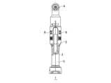
図2は、電動工具1の内部の概略構成を示す。電動工具1は、モータ軸10a、10bを有するモータ10と、先端工具を装着される出力軸4と、モータ10の回転出力を出力軸4に伝達する動力伝達機構11と、モータ10の動作を制御する制御部6とを備える。制御部6は、レバースイッチ3の操作量に応じて、ハウジング2の下端に装着されたバッテリパックの電力をモータ10に供給する。 FIG. 2 shows a schematic internal configuration of the
動力伝達機構11は、モータ出力によって出力軸4に間欠的な回転衝撃力を発生させるインパクト機構13を少なくとも有する。モータ10とインパクト機構13は、同じ回転軸線をもつように配置される。図示されるように、回転軸線に垂直な方向において、長尺のレバースイッチ3の一部がモータ10と重なる位置に設けられている。 The
インパクト機構13は、ハンマがばねによりアンビル側に付勢され、ハンマ爪とアンビル爪とが周方向に係合してハンマの回転がアンビルに伝達される構造を有する。アンビルに所定値を超える負荷トルクが加わると、ハンマはばね付勢力に抗して後退し、ハンマの後退によりハンマ爪とアンビル爪の係合が外れると、ハンマは回転しながら前進して、ハンマ爪がアンビル爪に回転方向の打撃を加える。インパクト機構13は、この構造により、出力軸4に間欠的な回転衝撃力を発生させる。 The
実施形態の動力伝達機構11は、インパクト機構13に加えて、モータ軸10aの回転を減速してインパクト機構13に伝達する減速機構12と、インパクト機構13の出力軸線の方向を90°曲げて出力軸4に伝達する方向変換機構14を有する。方向変換機構14は、アンビル出力軸先端に形成された第1かさ歯部と、出力軸4の根元に形成された第2かさ歯部を有し、第1かさ歯部と第2かさ歯部とが噛み合うことで出力軸線の方向を変換する。 In addition to the
インナーロータ型のモータ10を構成するロータおよびステータは、それぞれ別個独立にハウジング2に固定される。ハウジング2は、モータ10をハウジング2に組み付けるための構成として、ステータ保持部22、23、軸受保持部17、18を備える。ステータ保持部22、23、軸受保持部17、18は、一対の半割れハウジング部材をねじ締め等で結合することで、モータ10のステータ、軸受15、16をそれぞれ保持する。 A rotor and a stator that constitute the inner
ステータ保持部22は、ハウジング2の内周面に突設され、ステータの一端側、ここではステータの前端側の外周を保持するリブ部材である。ステータ保持部22は、一対の半割れハウジング部材のそれぞれに形成されたリブ部材によって構成され、複数のリブ部材でステータの前端側の外周を挟持して固定する。 The
ステータ保持部23は、ハウジング2の内周面に突設され、ステータの他端側、ここではステータの後端側の外周を保持するリブ部材である。ステータ保持部23は、一対の半割れハウジング部材のそれぞれに形成されたリブ部材によって構成され、複数のリブ部材でステータの後端側の外周を挟持して固定する。 The
軸受保持部17は、ハウジング2の内周面に突設され、前端側のモータ軸10aを支持する軸受15の外周を保持するリブ部材である。軸受保持部17は、一対の半割れハウジング部材のそれぞれに形成されたリブ部材によって構成され、複数のリブ部材で軸受15の外周を挟持して固定する。 The
軸受保持部18は、ハウジング2の内周面に突設され、後端側のモータ軸10bを支持する軸受16の外周を保持するリブ部材である。軸受保持部18は、一対の半割れハウジング部材のそれぞれに形成されたリブ部材によって構成され、複数のリブ部材で軸受16の外周を挟持して固定する。 The
実施形態の電動工具1は、制御部6によるトルク制御を実現するために、インパクト機構13により出力軸4に加えられた衝撃を検出する衝撃検出部30を備える。衝撃検出部30は、インパクト機構13による打撃衝撃を検出し、検出結果を電線7を通じて制御部6に供給する。制御部6は、衝撃検出部30の検出結果からねじ部材の着座判定を行って、打撃衝撃数をカウントし、着座判定後の打撃衝撃数がユーザにより設定されたトルク値に応じた数に到達すると、モータ10への通電を自動停止して、ねじ部材の締付を完了させる。 The
衝撃検出部30は、打撃衝撃を検出するショックセンサと、ショックセンサの出力を増幅して制御部6に供給する増幅器を含んで構成されてよい。たとえばショックセンサは圧電式ショックセンサであって、衝撃に応じた電圧信号を出力し、増幅器は、出力された電圧信号を増幅して制御部6に供給する。 The
高感度に打撃衝撃を検出するために、衝撃検出部30はインパクト機構13の近傍に配置されることが理想的である。図2に示すようにインパクト機構13はハウジング2内の前方側に配置されており、インパクト機構13の近傍に衝撃検出部30を配置しようとすると、配置スペース確保のためにハウジング2の前方側の径が太くなる結果を招く。電動工具1は、狭い空間に挿入して作業を行うことを目的としたアングル式電動工具であるため、特に前方側の太径化は回避したい。 Ideally, the
そこで実施形態の電動工具1では、衝撃検出部30が、モータ10の後端側に配置される。モータ10の後端側は配置スペースを確保しやすく、また、もともと作業者が把持する箇所であるため、細径化に対する要請は比較的低い。ハウジング2の前方側に配置したときと比べると、衝撃検出部30はインパクト機構13から若干離れるが、ハウジング2の前方側を太径化しなくてすむ利点がある。 Therefore, in the
衝撃検出部30を搭載した基板は、モータ10の後端側において、ハウジング2の内周面に突設された基板保持部20により保持される。基板保持部20がハウジング2の内周面に形成されることで、インパクト機構13による打撃衝撃は、ハウジング2から基板保持部20を介して衝撃検出部30により検出される。 The board on which the
なおインパクト機構13による打撃衝撃は、インパクト機構13に連結しているモータ10にも伝達される。ハウジング2は樹脂材料で形成されているが、モータ軸10a、10bは金属材料で形成されているため、衝撃の伝達効率は、モータ10の方がハウジング2よりも高い。そこで本発明者は、モータ10に伝達される打撃衝撃を効率的に衝撃検出部30に検出させるべく、モータ軸10bの軸受16を保持する軸受保持部18の近傍に、基板保持部20を設けることとした。これにより衝撃検出部30が、モータ10経由で伝達される打撃衝撃を効果的に検出できる。さらに実施形態では軸受保持部18と基板保持部20とを連結リブ21で連結して、軸受保持部18から基板保持部20への打撃衝撃の伝達効率を高めている。 The impact of the
衝撃検出部30による検出結果は、電線7から制御部6に供給される。上記したように制御部6は、ねじ部材の着座後の打撃衝撃数にもとづいて、モータ10の回転を自動停止させるトルク制御を実施してよい。 A detection result by the
以上、本発明を実施形態をもとに説明した。この実施形態は例示であり、それらの各構成要素あるいは各処理プロセスの組合せにいろいろな変形例が可能なこと、またそうした変形例も本発明の範囲にあることは当業者に理解されるところである。 The present invention has been described above based on the embodiments. It should be understood by those skilled in the art that this embodiment is an example, and that various modifications can be made to the combination of each component or each treatment process, and such modifications are also within the scope of the present invention. .
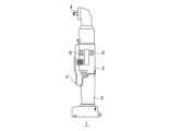
実施形態では、衝撃検出部30をモータ10の後端側に配置することを説明したが、レバースイッチ3とモータ10の間の空き空間を有効利用し、また配置位置をインパクト機構13に近づけるべく、衝撃検出部30を、モータ10とレバースイッチ3の間に配置してもよい。 In the embodiment, the
図3(a)は、衝撃検出部30をモータ10とレバースイッチ3の間に配置した一例を示す。基板保持部20aは、衝撃検出部30を搭載した基板を、モータ10の回転軸線に平行となる向きで保持する。モータ10とレバースイッチ3の間の空間は、回転軸線方向に比較的スペースを確保しやすく、搭載基板を回転軸線に平行となる向きで設けることで、空きスペースを有効に利用できる。 FIG. 3A shows an example in which the
図3(b)は、衝撃検出部30をモータ10とレバースイッチ3の間に配置した別の例を示す。基板保持部20bは、衝撃検出部30を搭載した基板を、モータ10の回転軸線に直交する向きで保持する。搭載基板を回転軸線に直交する向きで設けることで、電線7の引き回しが容易となる利点がある。 FIG. 3(b) shows another example in which the
本発明の態様の概要は、次の通りである。
本発明のある態様の電動工具(1)は、モータ軸(10a、10b)を有するモータ(10)と、先端工具を装着される出力軸(4)と、モータ出力によって出力軸(4)に間欠的な回転衝撃力を発生させるインパクト機構(13)とを備える。出力軸(4)は、モータ軸(10a、10b)に対して所定の角度をもって配置されており、電動工具(1)は、インパクト機構により出力軸に加えられた衝撃を検出する衝撃検出部(30)を備える。A summary of aspects of the invention follows.
An electric power tool (1) according to one aspect of the present invention comprises a motor (10) having motor shafts (10a, 10b), an output shaft (4) to which a tip tool is mounted, and a motor output to the output shaft (4). an impact mechanism (13) for generating an intermittent rotational impact force. The output shaft (4) is arranged at a predetermined angle with respect to the motor shafts (10a, 10b), and the power tool (1) includes an impact detection section ( 30).
衝撃検出部(30)は、モータ(10)の後端側に配置されてよい。ハウジング(2)の内周面には、モータ(10)の後端側モータ軸(10b)を支持する軸受(16)を保持する第1保持部(18)と、衝撃検出部(30)を搭載した基板を保持する第2保持部(20)と、が形成されており、第1保持部と第2保持部とがリブ(21)によって連結されていてよい。 The impact detector (30) may be arranged on the rear end side of the motor (10). A first holding portion (18) for holding a bearing (16) supporting a rear end motor shaft (10b) of a motor (10) and an impact detection portion (30) are provided on the inner peripheral surface of the housing (2). A second holding portion (20) for holding the mounted substrate is formed, and the first holding portion and the second holding portion may be connected by a rib (21).
モータ(10)とインパクト機構(13)は同じ回転軸線をもつように配置され、回転軸線に垂直な方向において、レバースイッチ(3)がモータ(10)と重なる位置に設けられ、衝撃検出部(30)を搭載した基板が、モータとレバースイッチの間に配置されてよい。このとき基板は、回転軸線に平行となる向きで設けられてよく、回転軸線に直交する向きで設けられてもよい。 The motor (10) and the impact mechanism (13) are arranged so as to have the same rotation axis, and the lever switch (3) is provided at a position overlapping the motor (10) in the direction perpendicular to the rotation axis. 30) may be placed between the motor and the lever switch. At this time, the substrate may be provided in a direction parallel to the rotation axis, or may be provided in a direction orthogonal to the rotation axis.
1・・・電動工具、2・・・ハウジング、3・・・レバースイッチ、4・・・出力軸、5・・・グリップ部、6・・・制御部、7・・・電線、8・・・空気穴構造、10・・・モータ、10a,10b・・・モータ軸、11・・・動力伝達機構、12・・・減速機構、13・・・インパクト機構、14・・・方向変換機構、15,16・・・軸受、17,18・・・軸受保持部、20・・・基板保持部、21・・・連結リブ、22,23・・・ステータ保持部、30・・・衝撃検出部。DESCRIPTION OF
Claims (5)
Translated fromJapanese先端工具を装着される出力軸と、
モータ出力によって、前記出力軸に間欠的な回転衝撃力を発生させるインパクト機構と、を備えた電動工具であって、前記出力軸は、前記モータ軸に対して所定の角度をもって配置されており、
前記インパクト機構により前記出力軸に加えられた衝撃を検出する衝撃検出部を備え、前記衝撃検出部は、前記モータの後端側の、作業者が把持するグリップ部に配置され、
ハウジングの内周面には、
前記モータの後端側モータ軸を支持する軸受を保持する第1保持部と、
前記衝撃検出部を搭載した基板を保持する第2保持部とが形成されており、
前記モータと前記インパクト機構は同じ回転軸線をもつように配置され、
回転軸線に垂直な方向において、レバースイッチがモータと重なる位置に設けられており、
前記衝撃検出部を搭載した前記基板が、前記モータと前記レバースイッチの間に配置されている、
ことを特徴とする電動工具。a motor having a motor shaft;
an output shaft to which the tip tool is attached;
an impact mechanism that generates an intermittent rotational impact force on theoutput shaft by a motor output, wherein the output shaft is arranged at a predetermined angle with respect to the motor shaft,
An impact detection unit for detecting impact applied to the output shaft by the impact mechanism is provided, the impact detection unit is arranged in a grip portion held by an operator on the rear end side of the motor,
On the inner peripheral surface of the housing,
a first holding portion that holds a bearing that supports the rear end side motor shaft of the motor;
a second holding portion for holding the board on which the impact detection portionis mounted;
the motor and the impact mechanism are arranged to have the same axis of rotation;
The lever switch is provided at a position overlapping the motor in the direction perpendicular to the rotation axis,
the board on which the impact detection unit is mounted is arranged between the motor and the lever switch;
A power tool characterized by:
ことを特徴とする請求項1に記載の電動工具。The impact mechanism is arranged on the front end side of the motor,
The power tool according to claim 1, characterized in that:
ことを特徴とする請求項1または2に記載の電動工具。The first holding portion and the second holding portion are connected by a rib,
The power tool according to claim 1 or 2, characterized in that:
ことを特徴とする請求項1に記載の電動工具。wherein the substrate is oriented parallel to the axis of rotation;
The power tool according to claim1 , characterized in that:
ことを特徴とする請求項1に記載の電動工具。wherein the substrate is oriented perpendicular to the axis of rotation;
The power tool according to claim1 , characterized in that:
Priority Applications (2)
| Application Number | Priority Date | Filing Date | Title |
|---|---|---|---|
| JP2017183631AJP7220362B2 (en) | 2017-09-25 | 2017-09-25 | Electric tool |
| PCT/JP2018/022881WO2019058664A1 (en) | 2017-09-25 | 2018-06-15 | Electric tool |
Applications Claiming Priority (1)
| Application Number | Priority Date | Filing Date | Title |
|---|---|---|---|
| JP2017183631AJP7220362B2 (en) | 2017-09-25 | 2017-09-25 | Electric tool |
Publications (2)
| Publication Number | Publication Date |
|---|---|
| JP2019058961A JP2019058961A (en) | 2019-04-18 |
| JP7220362B2true JP7220362B2 (en) | 2023-02-10 |
Family
ID=65809632
Family Applications (1)
| Application Number | Title | Priority Date | Filing Date |
|---|---|---|---|
| JP2017183631AActiveJP7220362B2 (en) | 2017-09-25 | 2017-09-25 | Electric tool |
Country Status (2)
| Country | Link |
|---|---|
| JP (1) | JP7220362B2 (en) |
| WO (1) | WO2019058664A1 (en) |
Citations (9)
| Publication number | Priority date | Publication date | Assignee | Title |
|---|---|---|---|---|
| JP2003165065A (en) | 2001-09-21 | 2003-06-10 | Makita Corp | Tightening tool |
| JP2006000972A (en) | 2004-06-17 | 2006-01-05 | Matsushita Electric Works Ltd | Impact tool |
| JP2007167959A (en) | 2003-06-25 | 2007-07-05 | 株式会社空研 | Screw tightening control method and impact power screw tightening tool |
| JP2009202238A (en) | 2008-02-26 | 2009-09-10 | Hitachi Koki Co Ltd | Portable power tool |
| JP2014200884A (en) | 2013-04-04 | 2014-10-27 | 株式会社マキタ | Angle tool and electric tool |
| JP2015517411A (en) | 2012-05-25 | 2015-06-22 | ローベルト ボツシユ ゲゼルシヤフト ミツト ベシユレンクテル ハフツングRobert Bosch Gmbh | Impact device unit |
| JP2016005866A (en) | 2015-10-09 | 2016-01-14 | 日立工機株式会社 | Electric tool and power tool |
| JP2016175144A (en) | 2015-03-19 | 2016-10-06 | パナソニックIpマネジメント株式会社 | Impact tool |
| JP2017071055A (en) | 2017-01-25 | 2017-04-13 | 株式会社マキタ | Screw tightening electric tool |
Family Cites Families (4)
| Publication number | Priority date | Publication date | Assignee | Title |
|---|---|---|---|---|
| JP3264157B2 (en)* | 1995-12-01 | 2002-03-11 | 日立工機株式会社 | Rotary impact tool |
| JP5403328B2 (en)* | 2009-02-02 | 2014-01-29 | 日立工機株式会社 | Electric drilling tool |
| JP2014069264A (en)* | 2012-09-28 | 2014-04-21 | Hitachi Koki Co Ltd | Electric power tool |
| EP3028820A1 (en)* | 2014-12-03 | 2016-06-08 | HILTI Aktiengesellschaft | Hand-held machine tool and control method therefor |
- 2017
- 2017-09-25JPJP2017183631Apatent/JP7220362B2/enactiveActive
- 2018
- 2018-06-15WOPCT/JP2018/022881patent/WO2019058664A1/ennot_activeCeased
Patent Citations (9)
| Publication number | Priority date | Publication date | Assignee | Title |
|---|---|---|---|---|
| JP2003165065A (en) | 2001-09-21 | 2003-06-10 | Makita Corp | Tightening tool |
| JP2007167959A (en) | 2003-06-25 | 2007-07-05 | 株式会社空研 | Screw tightening control method and impact power screw tightening tool |
| JP2006000972A (en) | 2004-06-17 | 2006-01-05 | Matsushita Electric Works Ltd | Impact tool |
| JP2009202238A (en) | 2008-02-26 | 2009-09-10 | Hitachi Koki Co Ltd | Portable power tool |
| JP2015517411A (en) | 2012-05-25 | 2015-06-22 | ローベルト ボツシユ ゲゼルシヤフト ミツト ベシユレンクテル ハフツングRobert Bosch Gmbh | Impact device unit |
| JP2014200884A (en) | 2013-04-04 | 2014-10-27 | 株式会社マキタ | Angle tool and electric tool |
| JP2016175144A (en) | 2015-03-19 | 2016-10-06 | パナソニックIpマネジメント株式会社 | Impact tool |
| JP2016005866A (en) | 2015-10-09 | 2016-01-14 | 日立工機株式会社 | Electric tool and power tool |
| JP2017071055A (en) | 2017-01-25 | 2017-04-13 | 株式会社マキタ | Screw tightening electric tool |
Also Published As
| Publication number | Publication date |
|---|---|
| WO2019058664A1 (en) | 2019-03-28 |
| JP2019058961A (en) | 2019-04-18 |
Similar Documents
| Publication | Publication Date | Title |
|---|---|---|
| JP5783895B2 (en) | Power tools | |
| US10040178B2 (en) | Power tool and rotary impact tool | |
| US7886635B2 (en) | Bolt or nut tightening device | |
| CN102335895A (en) | Power tool having circuit board | |
| JP7609621B2 (en) | Screw fastener and method for assembling the screw fastener | |
| JP6493530B2 (en) | Working machine | |
| US20140318822A1 (en) | Portable Power Tool | |
| JP2014104541A (en) | Hand-held electric tool | |
| JP6024974B2 (en) | Impact rotary tool | |
| EP2895300B1 (en) | Impact tightening tool | |
| JP7220362B2 (en) | Electric tool | |
| JP6494257B2 (en) | Actuator, drive device | |
| JPH09155755A (en) | Rotary impact tool | |
| JP2021109275A (en) | Impact tool | |
| EP4116035A1 (en) | Power machine tool | |
| JP5674027B2 (en) | Tightening tool | |
| JP7262058B2 (en) | Electric tool | |
| JP6601017B2 (en) | Working machine | |
| JP2012139766A (en) | Tightening tool and predetermined work detecting unit | |
| JP2012139767A (en) | Driving tool | |
| JP3155654U (en) | Electric rotary tool | |
| US11633845B2 (en) | Power machine tool | |
| JP2009262273A (en) | Impact rotary tool | |
| JP7364249B2 (en) | power tool machinery | |
| JP6411110B2 (en) | Electric torque wrench |
Legal Events
| Date | Code | Title | Description |
|---|---|---|---|
| RD04 | Notification of resignation of power of attorney | Free format text:JAPANESE INTERMEDIATE CODE: A7424 Effective date:20180417 | |
| A621 | Written request for application examination | Free format text:JAPANESE INTERMEDIATE CODE: A621 Effective date:20200519 | |
| A131 | Notification of reasons for refusal | Free format text:JAPANESE INTERMEDIATE CODE: A131 Effective date:20210330 | |
| A521 | Request for written amendment filed | Free format text:JAPANESE INTERMEDIATE CODE: A523 Effective date:20210528 | |
| A02 | Decision of refusal | Free format text:JAPANESE INTERMEDIATE CODE: A02 Effective date:20210907 | |
| A521 | Request for written amendment filed | Free format text:JAPANESE INTERMEDIATE CODE: A523 Effective date:20211206 | |
| C60 | Trial request (containing other claim documents, opposition documents) | Free format text:JAPANESE INTERMEDIATE CODE: C60 Effective date:20211206 | |
| A911 | Transfer to examiner for re-examination before appeal (zenchi) | Free format text:JAPANESE INTERMEDIATE CODE: A911 Effective date:20211215 | |
| C21 | Notice of transfer of a case for reconsideration by examiners before appeal proceedings | Free format text:JAPANESE INTERMEDIATE CODE: C21 Effective date:20211221 | |
| A912 | Re-examination (zenchi) completed and case transferred to appeal board | Free format text:JAPANESE INTERMEDIATE CODE: A912 Effective date:20220210 | |
| C211 | Notice of termination of reconsideration by examiners before appeal proceedings | Free format text:JAPANESE INTERMEDIATE CODE: C211 Effective date:20220215 | |
| C22 | Notice of designation (change) of administrative judge | Free format text:JAPANESE INTERMEDIATE CODE: C22 Effective date:20220607 | |
| C22 | Notice of designation (change) of administrative judge | Free format text:JAPANESE INTERMEDIATE CODE: C22 Effective date:20220712 | |
| C13 | Notice of reasons for refusal | Free format text:JAPANESE INTERMEDIATE CODE: C13 Effective date:20220816 | |
| A521 | Request for written amendment filed | Free format text:JAPANESE INTERMEDIATE CODE: A523 Effective date:20221006 | |
| C23 | Notice of termination of proceedings | Free format text:JAPANESE INTERMEDIATE CODE: C23 Effective date:20221213 | |
| C03 | Trial/appeal decision taken | Free format text:JAPANESE INTERMEDIATE CODE: C03 Effective date:20230110 | |
| C30A | Notification sent | Free format text:JAPANESE INTERMEDIATE CODE: C3012 Effective date:20230110 | |
| A61 | First payment of annual fees (during grant procedure) | Free format text:JAPANESE INTERMEDIATE CODE: A61 Effective date:20230117 | |
| R151 | Written notification of patent or utility model registration | Ref document number:7220362 Country of ref document:JP Free format text:JAPANESE INTERMEDIATE CODE: R151 |