JP7219833B2 - Devices for endovascular aortic repair and methods of use thereof - Google Patents
Devices for endovascular aortic repair and methods of use thereofDownload PDFInfo
- Publication number
- JP7219833B2 JP7219833B2JP2022037195AJP2022037195AJP7219833B2JP 7219833 B2JP7219833 B2JP 7219833B2JP 2022037195 AJP2022037195 AJP 2022037195AJP 2022037195 AJP2022037195 AJP 2022037195AJP 7219833 B2JP7219833 B2JP 7219833B2
- Authority
- JP
- Japan
- Prior art keywords
- frame
- proximal
- component
- valve
- distal
- Prior art date
- Legal status (The legal status is an assumption and is not a legal conclusion. Google has not performed a legal analysis and makes no representation as to the accuracy of the status listed.)
- Active
Links
Images


Classifications
- A—HUMAN NECESSITIES
- A61—MEDICAL OR VETERINARY SCIENCE; HYGIENE
- A61F—FILTERS IMPLANTABLE INTO BLOOD VESSELS; PROSTHESES; DEVICES PROVIDING PATENCY TO, OR PREVENTING COLLAPSING OF, TUBULAR STRUCTURES OF THE BODY, e.g. STENTS; ORTHOPAEDIC, NURSING OR CONTRACEPTIVE DEVICES; FOMENTATION; TREATMENT OR PROTECTION OF EYES OR EARS; BANDAGES, DRESSINGS OR ABSORBENT PADS; FIRST-AID KITS
- A61F2/00—Filters implantable into blood vessels; Prostheses, i.e. artificial substitutes or replacements for parts of the body; Appliances for connecting them with the body; Devices providing patency to, or preventing collapsing of, tubular structures of the body, e.g. stents
- A61F2/82—Devices providing patency to, or preventing collapsing of, tubular structures of the body, e.g. stents
- A—HUMAN NECESSITIES
- A61—MEDICAL OR VETERINARY SCIENCE; HYGIENE
- A61F—FILTERS IMPLANTABLE INTO BLOOD VESSELS; PROSTHESES; DEVICES PROVIDING PATENCY TO, OR PREVENTING COLLAPSING OF, TUBULAR STRUCTURES OF THE BODY, e.g. STENTS; ORTHOPAEDIC, NURSING OR CONTRACEPTIVE DEVICES; FOMENTATION; TREATMENT OR PROTECTION OF EYES OR EARS; BANDAGES, DRESSINGS OR ABSORBENT PADS; FIRST-AID KITS
- A61F2/00—Filters implantable into blood vessels; Prostheses, i.e. artificial substitutes or replacements for parts of the body; Appliances for connecting them with the body; Devices providing patency to, or preventing collapsing of, tubular structures of the body, e.g. stents
- A61F2/02—Prostheses implantable into the body
- A61F2/04—Hollow or tubular parts of organs, e.g. bladders, tracheae, bronchi or bile ducts
- A61F2/06—Blood vessels
- A61F2/07—Stent-grafts
- A—HUMAN NECESSITIES
- A61—MEDICAL OR VETERINARY SCIENCE; HYGIENE
- A61F—FILTERS IMPLANTABLE INTO BLOOD VESSELS; PROSTHESES; DEVICES PROVIDING PATENCY TO, OR PREVENTING COLLAPSING OF, TUBULAR STRUCTURES OF THE BODY, e.g. STENTS; ORTHOPAEDIC, NURSING OR CONTRACEPTIVE DEVICES; FOMENTATION; TREATMENT OR PROTECTION OF EYES OR EARS; BANDAGES, DRESSINGS OR ABSORBENT PADS; FIRST-AID KITS
- A61F2/00—Filters implantable into blood vessels; Prostheses, i.e. artificial substitutes or replacements for parts of the body; Appliances for connecting them with the body; Devices providing patency to, or preventing collapsing of, tubular structures of the body, e.g. stents
- A61F2/02—Prostheses implantable into the body
- A61F2/24—Heart valves ; Vascular valves, e.g. venous valves; Heart implants, e.g. passive devices for improving the function of the native valve or the heart muscle; Transmyocardial revascularisation [TMR] devices; Valves implantable in the body
- A61F2/2412—Heart valves ; Vascular valves, e.g. venous valves; Heart implants, e.g. passive devices for improving the function of the native valve or the heart muscle; Transmyocardial revascularisation [TMR] devices; Valves implantable in the body with soft flexible valve members, e.g. tissue valves shaped like natural valves
- A61F2/2418—Scaffolds therefor, e.g. support stents
- A—HUMAN NECESSITIES
- A61—MEDICAL OR VETERINARY SCIENCE; HYGIENE
- A61F—FILTERS IMPLANTABLE INTO BLOOD VESSELS; PROSTHESES; DEVICES PROVIDING PATENCY TO, OR PREVENTING COLLAPSING OF, TUBULAR STRUCTURES OF THE BODY, e.g. STENTS; ORTHOPAEDIC, NURSING OR CONTRACEPTIVE DEVICES; FOMENTATION; TREATMENT OR PROTECTION OF EYES OR EARS; BANDAGES, DRESSINGS OR ABSORBENT PADS; FIRST-AID KITS
- A61F2/00—Filters implantable into blood vessels; Prostheses, i.e. artificial substitutes or replacements for parts of the body; Appliances for connecting them with the body; Devices providing patency to, or preventing collapsing of, tubular structures of the body, e.g. stents
- A61F2/82—Devices providing patency to, or preventing collapsing of, tubular structures of the body, e.g. stents
- A61F2/856—Single tubular stent with a side portal passage
- A—HUMAN NECESSITIES
- A61—MEDICAL OR VETERINARY SCIENCE; HYGIENE
- A61F—FILTERS IMPLANTABLE INTO BLOOD VESSELS; PROSTHESES; DEVICES PROVIDING PATENCY TO, OR PREVENTING COLLAPSING OF, TUBULAR STRUCTURES OF THE BODY, e.g. STENTS; ORTHOPAEDIC, NURSING OR CONTRACEPTIVE DEVICES; FOMENTATION; TREATMENT OR PROTECTION OF EYES OR EARS; BANDAGES, DRESSINGS OR ABSORBENT PADS; FIRST-AID KITS
- A61F2/00—Filters implantable into blood vessels; Prostheses, i.e. artificial substitutes or replacements for parts of the body; Appliances for connecting them with the body; Devices providing patency to, or preventing collapsing of, tubular structures of the body, e.g. stents
- A61F2/95—Instruments specially adapted for placement or removal of stents or stent-grafts
- A61F2/962—Instruments specially adapted for placement or removal of stents or stent-grafts having an outer sleeve
- A—HUMAN NECESSITIES
- A61—MEDICAL OR VETERINARY SCIENCE; HYGIENE
- A61F—FILTERS IMPLANTABLE INTO BLOOD VESSELS; PROSTHESES; DEVICES PROVIDING PATENCY TO, OR PREVENTING COLLAPSING OF, TUBULAR STRUCTURES OF THE BODY, e.g. STENTS; ORTHOPAEDIC, NURSING OR CONTRACEPTIVE DEVICES; FOMENTATION; TREATMENT OR PROTECTION OF EYES OR EARS; BANDAGES, DRESSINGS OR ABSORBENT PADS; FIRST-AID KITS
- A61F2/00—Filters implantable into blood vessels; Prostheses, i.e. artificial substitutes or replacements for parts of the body; Appliances for connecting them with the body; Devices providing patency to, or preventing collapsing of, tubular structures of the body, e.g. stents
- A61F2/02—Prostheses implantable into the body
- A61F2/24—Heart valves ; Vascular valves, e.g. venous valves; Heart implants, e.g. passive devices for improving the function of the native valve or the heart muscle; Transmyocardial revascularisation [TMR] devices; Valves implantable in the body
- A—HUMAN NECESSITIES
- A61—MEDICAL OR VETERINARY SCIENCE; HYGIENE
- A61F—FILTERS IMPLANTABLE INTO BLOOD VESSELS; PROSTHESES; DEVICES PROVIDING PATENCY TO, OR PREVENTING COLLAPSING OF, TUBULAR STRUCTURES OF THE BODY, e.g. STENTS; ORTHOPAEDIC, NURSING OR CONTRACEPTIVE DEVICES; FOMENTATION; TREATMENT OR PROTECTION OF EYES OR EARS; BANDAGES, DRESSINGS OR ABSORBENT PADS; FIRST-AID KITS
- A61F2/00—Filters implantable into blood vessels; Prostheses, i.e. artificial substitutes or replacements for parts of the body; Appliances for connecting them with the body; Devices providing patency to, or preventing collapsing of, tubular structures of the body, e.g. stents
- A61F2/82—Devices providing patency to, or preventing collapsing of, tubular structures of the body, e.g. stents
- A61F2/86—Stents in a form characterised by the wire-like elements; Stents in the form characterised by a net-like or mesh-like structure
- A61F2/89—Stents in a form characterised by the wire-like elements; Stents in the form characterised by a net-like or mesh-like structure the wire-like elements comprising two or more adjacent rings flexibly connected by separate members
- A—HUMAN NECESSITIES
- A61—MEDICAL OR VETERINARY SCIENCE; HYGIENE
- A61F—FILTERS IMPLANTABLE INTO BLOOD VESSELS; PROSTHESES; DEVICES PROVIDING PATENCY TO, OR PREVENTING COLLAPSING OF, TUBULAR STRUCTURES OF THE BODY, e.g. STENTS; ORTHOPAEDIC, NURSING OR CONTRACEPTIVE DEVICES; FOMENTATION; TREATMENT OR PROTECTION OF EYES OR EARS; BANDAGES, DRESSINGS OR ABSORBENT PADS; FIRST-AID KITS
- A61F2/00—Filters implantable into blood vessels; Prostheses, i.e. artificial substitutes or replacements for parts of the body; Appliances for connecting them with the body; Devices providing patency to, or preventing collapsing of, tubular structures of the body, e.g. stents
- A61F2/82—Devices providing patency to, or preventing collapsing of, tubular structures of the body, e.g. stents
- A61F2/86—Stents in a form characterised by the wire-like elements; Stents in the form characterised by a net-like or mesh-like structure
- A61F2/90—Stents in a form characterised by the wire-like elements; Stents in the form characterised by a net-like or mesh-like structure characterised by a net-like or mesh-like structure
- A—HUMAN NECESSITIES
- A61—MEDICAL OR VETERINARY SCIENCE; HYGIENE
- A61F—FILTERS IMPLANTABLE INTO BLOOD VESSELS; PROSTHESES; DEVICES PROVIDING PATENCY TO, OR PREVENTING COLLAPSING OF, TUBULAR STRUCTURES OF THE BODY, e.g. STENTS; ORTHOPAEDIC, NURSING OR CONTRACEPTIVE DEVICES; FOMENTATION; TREATMENT OR PROTECTION OF EYES OR EARS; BANDAGES, DRESSINGS OR ABSORBENT PADS; FIRST-AID KITS
- A61F2/00—Filters implantable into blood vessels; Prostheses, i.e. artificial substitutes or replacements for parts of the body; Appliances for connecting them with the body; Devices providing patency to, or preventing collapsing of, tubular structures of the body, e.g. stents
- A61F2/0077—Special surfaces of prostheses, e.g. for improving ingrowth
- A61F2002/0081—Special surfaces of prostheses, e.g. for improving ingrowth directly machined on the prosthetic surface, e.g. holes, grooves
- A—HUMAN NECESSITIES
- A61—MEDICAL OR VETERINARY SCIENCE; HYGIENE
- A61F—FILTERS IMPLANTABLE INTO BLOOD VESSELS; PROSTHESES; DEVICES PROVIDING PATENCY TO, OR PREVENTING COLLAPSING OF, TUBULAR STRUCTURES OF THE BODY, e.g. STENTS; ORTHOPAEDIC, NURSING OR CONTRACEPTIVE DEVICES; FOMENTATION; TREATMENT OR PROTECTION OF EYES OR EARS; BANDAGES, DRESSINGS OR ABSORBENT PADS; FIRST-AID KITS
- A61F2/00—Filters implantable into blood vessels; Prostheses, i.e. artificial substitutes or replacements for parts of the body; Appliances for connecting them with the body; Devices providing patency to, or preventing collapsing of, tubular structures of the body, e.g. stents
- A61F2/02—Prostheses implantable into the body
- A61F2/04—Hollow or tubular parts of organs, e.g. bladders, tracheae, bronchi or bile ducts
- A61F2/06—Blood vessels
- A61F2002/061—Blood vessels provided with means for allowing access to secondary lumens
- A—HUMAN NECESSITIES
- A61—MEDICAL OR VETERINARY SCIENCE; HYGIENE
- A61F—FILTERS IMPLANTABLE INTO BLOOD VESSELS; PROSTHESES; DEVICES PROVIDING PATENCY TO, OR PREVENTING COLLAPSING OF, TUBULAR STRUCTURES OF THE BODY, e.g. STENTS; ORTHOPAEDIC, NURSING OR CONTRACEPTIVE DEVICES; FOMENTATION; TREATMENT OR PROTECTION OF EYES OR EARS; BANDAGES, DRESSINGS OR ABSORBENT PADS; FIRST-AID KITS
- A61F2/00—Filters implantable into blood vessels; Prostheses, i.e. artificial substitutes or replacements for parts of the body; Appliances for connecting them with the body; Devices providing patency to, or preventing collapsing of, tubular structures of the body, e.g. stents
- A61F2/02—Prostheses implantable into the body
- A61F2/04—Hollow or tubular parts of organs, e.g. bladders, tracheae, bronchi or bile ducts
- A61F2/06—Blood vessels
- A61F2002/065—Y-shaped blood vessels
- A61F2002/067—Y-shaped blood vessels modular
- A—HUMAN NECESSITIES
- A61—MEDICAL OR VETERINARY SCIENCE; HYGIENE
- A61F—FILTERS IMPLANTABLE INTO BLOOD VESSELS; PROSTHESES; DEVICES PROVIDING PATENCY TO, OR PREVENTING COLLAPSING OF, TUBULAR STRUCTURES OF THE BODY, e.g. STENTS; ORTHOPAEDIC, NURSING OR CONTRACEPTIVE DEVICES; FOMENTATION; TREATMENT OR PROTECTION OF EYES OR EARS; BANDAGES, DRESSINGS OR ABSORBENT PADS; FIRST-AID KITS
- A61F2210/00—Particular material properties of prostheses classified in groups A61F2/00 - A61F2/26 or A61F2/82 or A61F9/00 or A61F11/00 or subgroups thereof
- A61F2210/0009—Particular material properties of prostheses classified in groups A61F2/00 - A61F2/26 or A61F2/82 or A61F9/00 or A61F11/00 or subgroups thereof using materials or accessories for preventing galvanic or electrolytic corrosion
- A—HUMAN NECESSITIES
- A61—MEDICAL OR VETERINARY SCIENCE; HYGIENE
- A61F—FILTERS IMPLANTABLE INTO BLOOD VESSELS; PROSTHESES; DEVICES PROVIDING PATENCY TO, OR PREVENTING COLLAPSING OF, TUBULAR STRUCTURES OF THE BODY, e.g. STENTS; ORTHOPAEDIC, NURSING OR CONTRACEPTIVE DEVICES; FOMENTATION; TREATMENT OR PROTECTION OF EYES OR EARS; BANDAGES, DRESSINGS OR ABSORBENT PADS; FIRST-AID KITS
- A61F2210/00—Particular material properties of prostheses classified in groups A61F2/00 - A61F2/26 or A61F2/82 or A61F9/00 or A61F11/00 or subgroups thereof
- A61F2210/0014—Particular material properties of prostheses classified in groups A61F2/00 - A61F2/26 or A61F2/82 or A61F9/00 or A61F11/00 or subgroups thereof using shape memory or superelastic materials, e.g. nitinol
- A—HUMAN NECESSITIES
- A61—MEDICAL OR VETERINARY SCIENCE; HYGIENE
- A61F—FILTERS IMPLANTABLE INTO BLOOD VESSELS; PROSTHESES; DEVICES PROVIDING PATENCY TO, OR PREVENTING COLLAPSING OF, TUBULAR STRUCTURES OF THE BODY, e.g. STENTS; ORTHOPAEDIC, NURSING OR CONTRACEPTIVE DEVICES; FOMENTATION; TREATMENT OR PROTECTION OF EYES OR EARS; BANDAGES, DRESSINGS OR ABSORBENT PADS; FIRST-AID KITS
- A61F2210/00—Particular material properties of prostheses classified in groups A61F2/00 - A61F2/26 or A61F2/82 or A61F9/00 or A61F11/00 or subgroups thereof
- A61F2210/0057—Particular material properties of prostheses classified in groups A61F2/00 - A61F2/26 or A61F2/82 or A61F9/00 or A61F11/00 or subgroups thereof stretchable
- A—HUMAN NECESSITIES
- A61—MEDICAL OR VETERINARY SCIENCE; HYGIENE
- A61F—FILTERS IMPLANTABLE INTO BLOOD VESSELS; PROSTHESES; DEVICES PROVIDING PATENCY TO, OR PREVENTING COLLAPSING OF, TUBULAR STRUCTURES OF THE BODY, e.g. STENTS; ORTHOPAEDIC, NURSING OR CONTRACEPTIVE DEVICES; FOMENTATION; TREATMENT OR PROTECTION OF EYES OR EARS; BANDAGES, DRESSINGS OR ABSORBENT PADS; FIRST-AID KITS
- A61F2210/00—Particular material properties of prostheses classified in groups A61F2/00 - A61F2/26 or A61F2/82 or A61F9/00 or A61F11/00 or subgroups thereof
- A61F2210/0076—Particular material properties of prostheses classified in groups A61F2/00 - A61F2/26 or A61F2/82 or A61F9/00 or A61F11/00 or subgroups thereof multilayered, e.g. laminated structures
- A—HUMAN NECESSITIES
- A61—MEDICAL OR VETERINARY SCIENCE; HYGIENE
- A61F—FILTERS IMPLANTABLE INTO BLOOD VESSELS; PROSTHESES; DEVICES PROVIDING PATENCY TO, OR PREVENTING COLLAPSING OF, TUBULAR STRUCTURES OF THE BODY, e.g. STENTS; ORTHOPAEDIC, NURSING OR CONTRACEPTIVE DEVICES; FOMENTATION; TREATMENT OR PROTECTION OF EYES OR EARS; BANDAGES, DRESSINGS OR ABSORBENT PADS; FIRST-AID KITS
- A61F2220/00—Fixations or connections for prostheses classified in groups A61F2/00 - A61F2/26 or A61F2/82 or A61F9/00 or A61F11/00 or subgroups thereof
- A61F2220/0008—Fixation appliances for connecting prostheses to the body
- A61F2220/0016—Fixation appliances for connecting prostheses to the body with sharp anchoring protrusions, e.g. barbs, pins, spikes
- A—HUMAN NECESSITIES
- A61—MEDICAL OR VETERINARY SCIENCE; HYGIENE
- A61F—FILTERS IMPLANTABLE INTO BLOOD VESSELS; PROSTHESES; DEVICES PROVIDING PATENCY TO, OR PREVENTING COLLAPSING OF, TUBULAR STRUCTURES OF THE BODY, e.g. STENTS; ORTHOPAEDIC, NURSING OR CONTRACEPTIVE DEVICES; FOMENTATION; TREATMENT OR PROTECTION OF EYES OR EARS; BANDAGES, DRESSINGS OR ABSORBENT PADS; FIRST-AID KITS
- A61F2220/00—Fixations or connections for prostheses classified in groups A61F2/00 - A61F2/26 or A61F2/82 or A61F9/00 or A61F11/00 or subgroups thereof
- A61F2220/0025—Connections or couplings between prosthetic parts, e.g. between modular parts; Connecting elements
- A61F2220/0058—Connections or couplings between prosthetic parts, e.g. between modular parts; Connecting elements soldered or brazed or welded
- A—HUMAN NECESSITIES
- A61—MEDICAL OR VETERINARY SCIENCE; HYGIENE
- A61F—FILTERS IMPLANTABLE INTO BLOOD VESSELS; PROSTHESES; DEVICES PROVIDING PATENCY TO, OR PREVENTING COLLAPSING OF, TUBULAR STRUCTURES OF THE BODY, e.g. STENTS; ORTHOPAEDIC, NURSING OR CONTRACEPTIVE DEVICES; FOMENTATION; TREATMENT OR PROTECTION OF EYES OR EARS; BANDAGES, DRESSINGS OR ABSORBENT PADS; FIRST-AID KITS
- A61F2220/00—Fixations or connections for prostheses classified in groups A61F2/00 - A61F2/26 or A61F2/82 or A61F9/00 or A61F11/00 or subgroups thereof
- A61F2220/0025—Connections or couplings between prosthetic parts, e.g. between modular parts; Connecting elements
- A61F2220/0075—Connections or couplings between prosthetic parts, e.g. between modular parts; Connecting elements sutured, ligatured or stitched, retained or tied with a rope, string, thread, wire or cable
- A—HUMAN NECESSITIES
- A61—MEDICAL OR VETERINARY SCIENCE; HYGIENE
- A61F—FILTERS IMPLANTABLE INTO BLOOD VESSELS; PROSTHESES; DEVICES PROVIDING PATENCY TO, OR PREVENTING COLLAPSING OF, TUBULAR STRUCTURES OF THE BODY, e.g. STENTS; ORTHOPAEDIC, NURSING OR CONTRACEPTIVE DEVICES; FOMENTATION; TREATMENT OR PROTECTION OF EYES OR EARS; BANDAGES, DRESSINGS OR ABSORBENT PADS; FIRST-AID KITS
- A61F2230/00—Geometry of prostheses classified in groups A61F2/00 - A61F2/26 or A61F2/82 or A61F9/00 or A61F11/00 or subgroups thereof
- A61F2230/0002—Two-dimensional shapes, e.g. cross-sections
- A61F2230/0004—Rounded shapes, e.g. with rounded corners
- A61F2230/001—Figure-8-shaped, e.g. hourglass-shaped
- A—HUMAN NECESSITIES
- A61—MEDICAL OR VETERINARY SCIENCE; HYGIENE
- A61F—FILTERS IMPLANTABLE INTO BLOOD VESSELS; PROSTHESES; DEVICES PROVIDING PATENCY TO, OR PREVENTING COLLAPSING OF, TUBULAR STRUCTURES OF THE BODY, e.g. STENTS; ORTHOPAEDIC, NURSING OR CONTRACEPTIVE DEVICES; FOMENTATION; TREATMENT OR PROTECTION OF EYES OR EARS; BANDAGES, DRESSINGS OR ABSORBENT PADS; FIRST-AID KITS
- A61F2230/00—Geometry of prostheses classified in groups A61F2/00 - A61F2/26 or A61F2/82 or A61F9/00 or A61F11/00 or subgroups thereof
- A61F2230/0002—Two-dimensional shapes, e.g. cross-sections
- A61F2230/0028—Shapes in the form of latin or greek characters
- A61F2230/0034—D-shaped
- A—HUMAN NECESSITIES
- A61—MEDICAL OR VETERINARY SCIENCE; HYGIENE
- A61F—FILTERS IMPLANTABLE INTO BLOOD VESSELS; PROSTHESES; DEVICES PROVIDING PATENCY TO, OR PREVENTING COLLAPSING OF, TUBULAR STRUCTURES OF THE BODY, e.g. STENTS; ORTHOPAEDIC, NURSING OR CONTRACEPTIVE DEVICES; FOMENTATION; TREATMENT OR PROTECTION OF EYES OR EARS; BANDAGES, DRESSINGS OR ABSORBENT PADS; FIRST-AID KITS
- A61F2230/00—Geometry of prostheses classified in groups A61F2/00 - A61F2/26 or A61F2/82 or A61F9/00 or A61F11/00 or subgroups thereof
- A61F2230/0063—Three-dimensional shapes
- A61F2230/0067—Three-dimensional shapes conical
- A—HUMAN NECESSITIES
- A61—MEDICAL OR VETERINARY SCIENCE; HYGIENE
- A61F—FILTERS IMPLANTABLE INTO BLOOD VESSELS; PROSTHESES; DEVICES PROVIDING PATENCY TO, OR PREVENTING COLLAPSING OF, TUBULAR STRUCTURES OF THE BODY, e.g. STENTS; ORTHOPAEDIC, NURSING OR CONTRACEPTIVE DEVICES; FOMENTATION; TREATMENT OR PROTECTION OF EYES OR EARS; BANDAGES, DRESSINGS OR ABSORBENT PADS; FIRST-AID KITS
- A61F2250/00—Special features of prostheses classified in groups A61F2/00 - A61F2/26 or A61F2/82 or A61F9/00 or A61F11/00 or subgroups thereof
- A61F2250/0014—Special features of prostheses classified in groups A61F2/00 - A61F2/26 or A61F2/82 or A61F9/00 or A61F11/00 or subgroups thereof having different values of a given property or geometrical feature, e.g. mechanical property or material property, at different locations within the same prosthesis
- A61F2250/0039—Special features of prostheses classified in groups A61F2/00 - A61F2/26 or A61F2/82 or A61F9/00 or A61F11/00 or subgroups thereof having different values of a given property or geometrical feature, e.g. mechanical property or material property, at different locations within the same prosthesis differing in diameter
- A—HUMAN NECESSITIES
- A61—MEDICAL OR VETERINARY SCIENCE; HYGIENE
- A61F—FILTERS IMPLANTABLE INTO BLOOD VESSELS; PROSTHESES; DEVICES PROVIDING PATENCY TO, OR PREVENTING COLLAPSING OF, TUBULAR STRUCTURES OF THE BODY, e.g. STENTS; ORTHOPAEDIC, NURSING OR CONTRACEPTIVE DEVICES; FOMENTATION; TREATMENT OR PROTECTION OF EYES OR EARS; BANDAGES, DRESSINGS OR ABSORBENT PADS; FIRST-AID KITS
- A61F2250/00—Special features of prostheses classified in groups A61F2/00 - A61F2/26 or A61F2/82 or A61F9/00 or A61F11/00 or subgroups thereof
- A61F2250/0014—Special features of prostheses classified in groups A61F2/00 - A61F2/26 or A61F2/82 or A61F9/00 or A61F11/00 or subgroups thereof having different values of a given property or geometrical feature, e.g. mechanical property or material property, at different locations within the same prosthesis
- A61F2250/0048—Special features of prostheses classified in groups A61F2/00 - A61F2/26 or A61F2/82 or A61F9/00 or A61F11/00 or subgroups thereof having different values of a given property or geometrical feature, e.g. mechanical property or material property, at different locations within the same prosthesis differing in mechanical expandability, e.g. in mechanical, self- or balloon expandability
- A—HUMAN NECESSITIES
- A61—MEDICAL OR VETERINARY SCIENCE; HYGIENE
- A61F—FILTERS IMPLANTABLE INTO BLOOD VESSELS; PROSTHESES; DEVICES PROVIDING PATENCY TO, OR PREVENTING COLLAPSING OF, TUBULAR STRUCTURES OF THE BODY, e.g. STENTS; ORTHOPAEDIC, NURSING OR CONTRACEPTIVE DEVICES; FOMENTATION; TREATMENT OR PROTECTION OF EYES OR EARS; BANDAGES, DRESSINGS OR ABSORBENT PADS; FIRST-AID KITS
- A61F2250/00—Special features of prostheses classified in groups A61F2/00 - A61F2/26 or A61F2/82 or A61F9/00 or A61F11/00 or subgroups thereof
- A61F2250/0058—Additional features; Implant or prostheses properties not otherwise provided for
- A61F2250/0069—Sealing means
Landscapes
- Health & Medical Sciences (AREA)
- Engineering & Computer Science (AREA)
- Biomedical Technology (AREA)
- Cardiology (AREA)
- Oral & Maxillofacial Surgery (AREA)
- Transplantation (AREA)
- Heart & Thoracic Surgery (AREA)
- Vascular Medicine (AREA)
- Life Sciences & Earth Sciences (AREA)
- Animal Behavior & Ethology (AREA)
- General Health & Medical Sciences (AREA)
- Public Health (AREA)
- Veterinary Medicine (AREA)
- Gastroenterology & Hepatology (AREA)
- Pulmonology (AREA)
- Prostheses (AREA)
Description
Translated fromJapanese [関連出願の相互参照]
本出願は、2011年12月6日にAli Shahriari氏により出願された「Transcathetar Aortic Valve for Endovascular Aortic Repair」と題する、米国特許法第119条に規定される米国仮特許出願第61/567,458号の優先権を主張し、その内容は参照により本明細書に明白に援用される。本出願はまた、2012年11月7日にAli Shahriari氏により出願された「Transcathetar Aortic Valve for Endovascular Aortic Repair」と題する、米国特許法第119条に規定される米国仮特許出願第61/723,446号の優先権を主張し、その内容は参照により本明細書に明白に援用される。[Cross reference to related applications]
119, entitled "Transcathetar Aortic Valve for Endovascular Aortic Repair," filed Dec. 6, 2011 by Ali Shahriari. No. 1, the contents of which are expressly incorporated herein by reference. 119, entitled "Transcathetar Aortic Valve for Endovascular Aortic Repair," filed Nov. 7, 2012 by Ali Shahriari. 446, the contents of which are expressly incorporated herein by reference.
本発明は、大動脈弁疾患、大動脈弁狭窄症、上行大動脈瘤、大動脈弁閉鎖不全症、大動脈弁逆流、上行動脈瘤、二尖弁症、および/またはA型解離の修復をはじめとする、血管内大動脈修復用デバイスおよびその使用方法に関する。 The present invention is useful for repairing aortic valve disease, aortic stenosis, ascending aortic aneurysm, aortic regurgitation, aortic regurgitation, ascending aneurysm, bicuspid valve disease, and/or type A dissection. A device for internal aortic repair and methods of use thereof.
正常な大動脈基部および上行大動脈は、大動脈弁輪、バルサルバ洞、STジャンクション(sinutubular junction)および管状部分から構成される。上行大動脈瘤の血管内修復の専門家らが直面している問題として以下のものが挙げられる。すなわち、STジャンクションの位置において、非常に短い近位ランディングゾーンがあること、患者によってそれぞれ冠動脈の構造が異なること、そして多くの場合、弁閉鎖不全症または狭窄症のいずれかを伴う大動脈弁の病変があること、である。非特許文献1に記載されるように、一般に、上行大動脈の病変には3つの基本的なタイプがあり、それぞれAタイプ、Bタイプ、Cタイプと称される。これらについて、先行技術文献より複写した図1A~図1Cを参照しつつ以下に詳述する。なお、非特許文献1の開示内容は参照により本明細書に完全に援用される。 The normal aortic root and ascending aorta consist of the aortic annulus, sinus of Valsalva, ST junction (sinutubular junction) and tubular segments. Problems faced by practitioners of endovascular repair of ascending aortic aneurysms include: a very short proximal landing zone at the ST junction; different coronary anatomy in each patient; and aortic valve lesions, often accompanied by either insufficiency or stenosis. There is, is. As described in Non-Patent Document 1, there are generally three basic types of lesions in the ascending aorta, referred to as A, B, and C types, respectively. These will be described in detail below with reference to FIGS. 1A-1C reproduced from the prior art document. The disclosure content of Non-Patent Document 1 is fully incorporated herein by reference.
Aタイプ動脈瘤は、若年患者およびマルファン症候群等の結合組織障害の患者に最も一般的に見られる。Aタイプ動脈瘤の解剖学的特徴は、バルサルバ洞の拡大であり、これは大動脈弁輪の拡大を伴う場合と伴わない場合がある。STジャンクションはもっとも頻繁に拡大する。弁の状態は、正常弁、狭窄弁、または弁閉鎖不全症であり得る。Aタイプ動脈瘤の一例を図1Aに示す。 Type A aneurysms are most commonly seen in young patients and those with connective tissue disorders such as Marfan's syndrome. An anatomical feature of a type A aneurysm is enlargement of the sinus of Valsalva, with or without enlargement of the aortic annulus. The ST junction expands most frequently. The valve condition can be normal valve, stenotic valve, or valvular insufficiency. An example of a type A aneurysm is shown in FIG. 1A.
Bタイプ動脈瘤の解剖学的特徴は管状部分の拡大である。初期においては、STジャンクションは正常またはやや拡大している程度だが、動脈瘤の成長に伴ってSTジャンクションが引き伸ばされ、最終的には大動脈弁閉鎖不全症を引き起こす。弁の状態は、正常弁、狭窄弁、または弁閉鎖不全であり得る。動脈瘤の大半は管状大動脈の位置にある。Bタイプ動脈瘤の一例を図1Bに示す。 An anatomical feature of a type B aneurysm is an enlarged tubular segment. Initially, the ST junction is normal or slightly enlarged, but as the aneurysm grows, the ST junction is stretched, eventually causing aortic regurgitation. The valve condition may be normal valve, stenotic valve, or valvular insufficiency. The majority of aneurysms are located in the tubular aorta. An example of a B-type aneurysm is shown in FIG. 1B.
Cタイプ動脈瘤の解剖学的特徴は、大動脈のバルサルバ洞、STジャンクション、および管状部分の拡大である。弁の状態は、正常弁、狭窄弁、または弁閉鎖不全であり得る。Bタイプ動脈瘤およびCタイプ動脈瘤は高齢患者群に最も一般的に見られる。Cタイプ動脈瘤の一例を図1Cに示す。 Anatomical features of type C aneurysms are enlargement of the sinuses of Valsalva, the ST junction, and tubular portions of the aorta. The valve condition may be normal valve, stenotic valve, or valvular insufficiency. B-type aneurysms and C-type aneurysms are most commonly seen in the elderly patient group. An example of a C-type aneurysm is shown in FIG. 1C.
上行大動脈瘤の血管内修復を行う際に臨床的に用いられているデバイスがある。経カテーテル弁は臨床治療で実現化されてはいるが、臨床利用されているものの中で、複数のタイプの上行大動脈瘤の血管内修復に利用する目的で設計されたものは未だない。上行大動脈瘤の様々な解剖学的変異の治療、および大動脈内における効果的な近位のシール領域および遠位のシール領域の作製を可能とし、かつ将来的な弁の再処置を許容しつつも耐久性のある弁部品を有するデバイスが、実際に必要とされている。また、患者集団間で異なる様々な冠状動脈の解剖学的変異の治療を可能とし、冠状動脈の圧迫を防止しつつも将来的な冠状動脈の再処置を許容し、起こりうる弁傍漏出の治療を可能にするデバイスも必要とされている。 There are devices in clinical use in performing endovascular repair of ascending aortic aneurysms. Although transcatheter valves have become clinically viable, none in clinical use have yet been designed for use in the endovascular repair of multiple types of ascending aortic aneurysms. Allowing treatment of various anatomical variations of ascending aortic aneurysms and creation of effective proximal and distal sealing areas within the aorta, while allowing for future re-treatment of the valve A real need exists for a device with durable valve components. It also allows treatment of various coronary anatomic variations that vary between patient populations, prevents coronary artery compression while allowing for future coronary retreatment, and treats possible paravalvular leaks. There is also a need for devices that allow
本開示の一態様によれば、上行大動脈瘤の血管内修復用エンドグラフトデバイスが開示される。エンドグラフトデバイスは、第1のプロテーゼ部品を備え、該第1のプロテーゼ部品は、近位フレームと、該近位フレームに固定されて、該第1のプロテーゼ部品の遠位端まで延在する遠位フレームと、を有する。エンドグラフトデバイスはまた、前記第1のプロテーゼ部品に固定され、前記近位フレームに隣接して位置する、少なくとも1つの導管と、前記第1のプロテーゼ部品の近位端に固定された第2のプロテーゼ部品を備える。第2のプロテーゼ部品は、前記第2のプロテーゼ部品の近位端から遠位方向に延在するバルーン拡張型フレームと、該バルーン拡張型フレームに接続され、前記第2のプロテーゼ部品の遠位端まで延在する自己拡張型フレームと、を備える。エンドグラフトデバイスは、さらに、前記第2のプロテーゼ部品の近位端において、前記バルーン拡張型フレームに固定した弁要素を備える。 According to one aspect of the present disclosure, an endograft device for endovascular repair of ascending aortic aneurysms is disclosed. The endograft device includes a first prosthetic component including a proximal frame and a distal end secured to the proximal frame and extending to a distal end of the first prosthetic component. a position frame; The endograft device also includes at least one conduit secured to the first prosthetic component and located adjacent the proximal frame, and a second conduit secured to the proximal end of the first prosthetic component. Equipped with prosthesis components. A second prosthesis component includes a balloon expandable frame extending distally from a proximal end of the second prosthesis component, a balloon expandable frame connected to the balloon expandable frame and a distal end of the second prosthesis component. a self-expanding frame extending to the The endograft device further comprises a valve element secured to the balloon expandable frame at the proximal end of the second prosthetic component.
いくつかの実施形態において、自己拡張型フレームを砂時計形状とすることができる。いくつかの実施形態において、自己拡張型フレームは、近位端と遠位端との間で内向きにテーパした第1の部分を備えていてもよい。エンドグラフトデバイスは、さらに、前記第1の部分の遠位端に固定した近位端を有する第2の部分を備えていてもよい。第2の部分は、該第2の部分の近位端と遠位端との間で外向きにテーパしていてもよい。さらに、いくつかの実施形態では、第1部分の近位端は、バルーン拡張型フレームの遠位端に連結していてもよい。 In some embodiments, the self-expanding frame can be hourglass shaped. In some embodiments, the self-expanding frame may comprise a first portion that tapers inwardly between the proximal and distal ends. The endograft device may further comprise a second portion having a proximal end secured to the distal end of said first portion. The second portion may taper outwardly between the proximal and distal ends of the second portion. Additionally, in some embodiments, the proximal end of the first portion may be coupled to the distal end of the balloon expandable frame.
いくつかの実施形態において、自己拡張型フレームは、第1の部分の近位端から近位方向に延在する第3の部分を備えていてもよい。該第3の部分は、その内部に画定した通路を有していてもよく、バルーン拡張型フレームは、自己拡張型フレームの第3の部分の該通路内に配置してもよい。いくつかの実施形態においては、バルーン拡張型フレームは、該バルーン拡張型フレームの外表面が自己拡張型フレームの内表面から離間している、未拡張位置と、前記バルーン拡張型フレームの外表面が自己拡張型フレームの内表面と係合する、拡張位置、との間で拡張可能とすることができる。 In some embodiments, the self-expanding frame may comprise a third portion extending proximally from the proximal end of the first portion. The third portion may have a passageway defined therein, and the balloon expandable frame may be disposed within the passageway of the third portion of the self-expanding frame. In some embodiments, the balloon-expandable frame has an unexpanded position, wherein the outer surface of the balloon-expandable frame is spaced from the inner surface of the self-expanding frame; It may be expandable between an expanded position, which engages an inner surface of the self-expanding frame.
いくつかの実施形態において、前記自己拡張型フレームの第3の部分には複数の線維を取り付けてもよい。バルーン拡張型フレームが拡張位置にあるとき、前記バルーン拡張型フレームの外表面は、複数の線維と係合することができる。 In some embodiments, a plurality of fibers may be attached to the third portion of the self-expanding frame. An outer surface of the balloon-expandable frame can engage a plurality of fibers when the balloon-expandable frame is in the expanded position.
いくつかの実施形態において、第1のプロテーゼ部品の近位フレームは、その内部に画定した通路を有し、第2のプロテーゼ部品の遠位端を、前記第1のプロテーゼ部品の通路内に位置させてもよい。 In some embodiments, the proximal frame of the first prosthesis component has a passageway defined therein for positioning the distal end of the second prosthesis component within the passageway of said first prosthesis component. You may let
いくつかの実施形態において、導管は、前記第1のプロテーゼ部品の両側に位置する1対の導管であってもよい。また、いくつかの実施形態において、導管は、第1のプロテーゼ部品の近位端と隣接して位置する近位開口を有していてもよい。 In some embodiments, the conduits may be a pair of conduits on opposite sides of said first prosthetic component. Also, in some embodiments, the conduit may have a proximal opening located adjacent the proximal end of the first prosthetic component.
いくつかの実施形態において、近位フレームは、第2のプロテーゼ部品の遠位端に固定した第1の部分と、該第1の部分に連結する第2の部分を備えていてもよい。第2の部分は、遠位端と、該第1の部分と連結するする近位端との間で外向きにテーパしていてもよい。導管は、近位フレームの第2の部分内に画定した遠位開口を有していてもよい。 In some embodiments, the proximal frame may comprise a first portion secured to the distal end of the second prosthesis component and a second portion coupled to the first portion. The second portion may taper outwardly between a distal end and a proximal end that connects the first portion. The conduit may have a distal opening defined within the second portion of the proximal frame.
また、いくつかの実施形態において、エンドグラフトデバイスは、少なくとも1つの導管の近位開口内に位置する遠位端、および冠状動脈内に位置するよう構成した近位端、を有するステントを備えていてもよい。 Also, in some embodiments, the endograft device comprises a stent having a distal end positioned within the proximal opening of the at least one conduit and a proximal end configured to be positioned within a coronary artery. may
いくつかの実施形態において、第2のプロテーゼ部品の外表面、および第1のプロテーゼ部品の近位フレームの外表面を被覆して、各表面への流体の透過を防止してもよい。また、第1のプロテーゼ部品の遠位フレームの外表面を被覆せずに、該表面への流体の透過を可能としてもよい。 In some embodiments, the outer surface of the second prosthetic component and the outer surface of the proximal frame of the first prosthetic component may be coated to prevent fluid permeation to each surface. Also, the outer surface of the distal frame of the first prosthesis component may be left uncovered to allow fluid to permeate that surface.
別の態様によれば、経カテーテル弁が開示される。経カテーテル弁は、フレーム部品を備えるが、該フレーム部分は、該フレーム部品の近位端から遠位方向に延在するバルーン拡張型フレームと、該バルーン拡張型フレームに固定される自己拡張型フレームを備える。自己拡張型フレームは、近位端と遠位端との間で内向きにテーパする第の1部分と、遠位端と、第1部分の遠位端に固定した近位端との間で、外向きにテーパする第2の部分を備える。弁要素は、フレーム部品の近位端において、前記バルーン拡張型フレーム内に位置する。 According to another aspect, a transcatheter valve is disclosed. The transcatheter valve includes a frame component, the frame portion including a balloon expandable frame extending distally from a proximal end of the frame component and a self-expanding frame secured to the balloon expandable frame. Prepare. The self-expanding frame has a first portion that tapers inwardly between a proximal end and a distal end; and a proximal end that is fixed to the distal end of the first portion. , with a second portion tapering outwardly. A valve element is located within the balloon expandable frame at the proximal end of the frame component.
いくつかの実施形態において、前記フレーム部品は二重フレーム部品であってもよい。自己拡張型フレームは、二重フレーム部品の外部フレームであり、その内部に画定した通路を有していてもよい。バルーン拡張型フレームは、前記二重フレーム部品の内部フレームであり、前記自己拡張型フレーム内に画定した通路内に位置していてもよい。また、バルーン拡張型フレームは、前記バルーン拡張型フレームの外表面が前記自己拡張型フレームの内表面から離間している、未拡張位置と、前記バルーン拡張型フレームの外表面が前記自己拡張型フレームの内表面と係合する、拡張位置との間で拡張可能としてもよい。 In some embodiments, the frame part may be a double frame part. A self-expanding frame is the outer frame of a dual frame component and may have a defined passageway therein. A balloon expandable frame may be the inner frame of the dual frame component and may be located within a passageway defined within the self-expanding frame. Also, the balloon-expandable frame has an unexpanded position, wherein an outer surface of the balloon-expandable frame is spaced from an inner surface of the self-expanding frame, and an outer surface of the balloon-expandable frame that extends from the self-expanding frame. It may be expandable between expanded positions that engage an inner surface of the .
いくつかの実施形態においては、前記自己拡張型フレームに複数の線維を取り付けてもよい。バルーン拡張型フレームが拡張位置にあるとき、バルーン拡張型フレームの外表面は前記複数の線維と係合しうる。また、いくつかの実施形態においては、自己拡張型フレームの第1の部分の外表面を被覆せずに、該表面へ流体を透過可能としてもよく、自己拡張型フレームの第2の部分の外表面を被覆して、該表面への流体の透過を防止してもよい。 In some embodiments, multiple fibers may be attached to the self-expanding frame. An outer surface of the balloon-expandable frame may engage the plurality of fibers when the balloon-expandable frame is in the expanded position. Also, in some embodiments, the outer surface of the first portion of the self-expanding frame may be left uncovered to allow fluid to pass therethrough, and the outer surface of the second portion of the self-expanding frame may be permeable to the surface. The surface may be coated to prevent fluid permeation to the surface.
いくつかの実施形態において、自己拡張型フレームは、第2の部分から遠位方向に延在する長尺部分を備えていてもよい。長尺部分の長さは、第1部分と第2部分を組み合わせた長さより長くてもよい。また、いくつかの実施形態において、自己拡張型フレームは、コラーゲンおよびヒドロゲルのうちの少なくとも一方により被覆されていてもよい。いくつかの実施形態において、弁要素は、二尖弁または三尖弁であってもよい。 In some embodiments, the self-expanding frame may comprise an elongate portion extending distally from the second portion. The length of the elongated portion may be longer than the combined length of the first portion and the second portion. Also, in some embodiments, the self-expanding frame may be coated with at least one of collagen and hydrogel. In some embodiments, the valve element may be bicuspid or tricuspid.
別の態様によれば、患者の大動脈を修復する方法が開示される。該方法は、第1のプロテーゼ部品を前記患者の大動脈に導入して、前記第1のプロテーゼ部品の近位フレームを上行大動脈内に位置させ、前記第1のプロテーゼ部品の遠位フレームを前記患者の大動脈の大動脈弓内に位置させるようにした、導入するステップと、前記第1のプロテーゼ部品内に画定した導管を通して、被覆ステントを前記患者の大動脈の冠状動脈に進めるステップと、第2のプロテーゼ部品を、前記患者の大動脈内で、前記第1のプロテーゼ部品の近位端と固定するステップと、前記第2のプロテーゼ部品の近位部を拡張して、前記患者の大動脈の大動脈弁輪に係合させて、前記近位部に固定された弁要素を、前記冠動脈の近位である大動脈弁輪内に位置させるようにした、拡張するステップと、を含む。 According to another aspect, a method of repairing a patient's aorta is disclosed. The method includes introducing a first prosthetic component into the patient's aorta, positioning a proximal frame of the first prosthetic component within the ascending aorta, and positioning a distal frame of the first prosthetic component into the patient's aorta. introducing, adapted to be positioned within the aortic arch of the aorta; advancing a covered stent through a conduit defined in the first prosthetic component into a coronary artery of the patient's aorta; securing a component to the proximal end of the first prosthetic component within the patient's aorta; and expanding the proximal portion of the second prosthetic component to the aortic annulus of the patient's aorta and expanding into engagement such that the valve element secured to the proximal portion is positioned within the aortic annulus proximal to the coronary artery.
いくつかの実施形態において、第2のプロテーゼ部品の近位部を拡張するステップは、バルーン拡張型フレームを動作するステップを含んでもよい。また、いくつかの実施形態において、第2のプロテーゼ部品の近位部を拡張するステップは、自己拡張型フレームを拡張して、前記大動脈弁輪と係合させるステップを含んでもよく、バルーン拡張型フレームを動作するステップは、前記自己拡張型フレームが前記大動脈弁輪と係合した後に、前記バルーン拡張型フレームの外表面を伸展させて、前記自己拡張型フレームの内表面と係合させるようにするステップと、を含んでいてもよい。 In some embodiments, expanding the proximal portion of the second prosthesis component may include operating a balloon expandable frame. Also, in some embodiments, expanding the proximal portion of the second prosthesis component may include expanding a self-expanding frame into engagement with the aortic annulus, the balloon expandable Operating the frame extends the outer surface of the balloon-expandable frame into engagement with the inner surface of the self-expanding frame after the self-expanding frame engages the aortic annulus. and .
いくつかの実施形態において、バルーン拡張型フレームを動作するステップは、該バルーン拡張型フレームの外表面を伸展させて、前記大動脈弁輪と係合させるステップを含みうる。 In some embodiments, operating the balloon expandable frame can include stretching an outer surface of the balloon expandable frame into engagement with the aortic annulus.
いくつかの実施形態において、第2のプロテーゼ部品の外表面および前記第1のプロテーゼ部品の近位フレームの外表面を被覆して、該表面への流体の透過を防止してもよい。また、第1のプロテーゼ部品の遠位フレームの外表面を被覆せずに、該表面への流体の透過を可能としてもよい。 In some embodiments, the outer surface of the second prosthetic component and the outer surface of the proximal frame of said first prosthetic component may be coated to prevent fluid permeation therethrough. Also, the outer surface of the distal frame of the first prosthesis component may be left uncovered to allow fluid to permeate that surface.
いくつかの実施形態において、患者の大動脈へ前記第1のプロテーゼ部品を導入するステップ、および被覆ステントを、前記第1のプロテーゼ部品内に画定した前記導管内を通して患者の大動脈の冠状動脈へ進めるステップは、第1の外科処置において行ってもよい。またある実施形態においては、第2のプロテーゼ部品を、前記第1のプロテーゼ部品の近位端に固定するステップ、および前記第2のプロテーゼ部品の近位部を拡張して、前記患者の大動脈の大動脈弁輪と係合させるステップは、前記第1の外科処置とは別の第2の外科処置において行ってもよい。 In some embodiments, introducing the first prosthetic component into the patient's aorta and advancing a covered stent through the conduit defined in the first prosthetic component and into a coronary artery of the patient's aorta. may be performed in the first surgical procedure. In another embodiment, securing a second prosthetic component to the proximal end of the first prosthetic component and expanding the proximal portion of the second prosthetic component to extend the patient's aorta. The step of engaging the aortic annulus may be performed in a second surgical procedure separate from said first surgical procedure.
いくつかの実施形態において、患者の大動脈を修復する方法は、また、第2のプロテーゼ部品を上行大動脈に導入してから第1のプロテーゼ部品を導入するステップを含んでもよい。 In some embodiments, the method of repairing a patient's aorta may also include introducing a second prosthetic component into the ascending aorta prior to introducing the first prosthetic component.
以下に、本発明の各実施例を、添付図面を参照してより詳細に説明する。 Below, each embodiment of the invention will be described in more detail with reference to the accompanying drawings.
本開示の概念は種々の変形例および変更例へ改変可能であるが、その特定の例示的な実施形態を例として図面中に示し、本明細書においてで詳細に説明する。しなしながら、本発明の概念を、その開示した特定の形態に限定する意図はないことを理解されたい。むしろ、例示の実施形態により、添付の特許請求の範囲に規定した発明の精神および範囲内に含まれる全ての変形例、その等価物、変更例を含むことを意図したものである。 While the concepts of this disclosure are susceptible to various modifications and alterations, specific illustrative embodiments thereof have been shown by way of example in the drawings and will herein be described in detail. However, it should be understood that there is no intention to limit the inventive concepts to the particular forms disclosed. Rather, the illustrated embodiments are intended to cover all modifications, equivalents and modifications coming within the spirit and scope of the invention as defined in the appended claims.
本明細書全体を通して、「前面」、「後部」、「内側」、「外側」、「上位」、「下位」、「遠位」、「近位」等、解剖学に関連して用いられる用語を、本明細書に記載の整形外科インプラントや外科用機械に言及する際、および患者の生来組織に言及する際に使用するが、これらの用語の意味は、解剖学研究においても整形外科分野においても十分に理解されている。明細書および請求の範囲においては、これらの解剖学に関連して用いられる用語は、別段の記載がない限り、その十分理解されている意味と同等の意味で使用される。例えば、「近位」という用語は、心臓から概ね最も近い方向を意味し、また「遠位」という用語は、心臓から概ね最も離れた方向を意味する。 Terms used throughout the specification in relation to anatomy such as "anterior", "posterior", "medial", "lateral", "superior", "inferior", "distal", "proximal" is used when referring to the orthopedic implants and surgical machines described herein, and when referring to the native tissue of a patient, but the meaning of these terms applies both in the study of anatomy and in the field of orthopedics. is also well understood. In the specification and claims, these anatomical terms are used equivalent to their well-understood meanings unless otherwise indicated. For example, the term "proximal" refers to the direction generally closest to the heart, and the term "distal" refers to the direction generally furthest from the heart.
図2~図16に、血管内プロテーゼデバイスまたはエンドグラフトデバイス10(以下「デバイス10」)の例示的な設計を示す。デバイス10は、ほとんどのタイプの上行大動脈瘤を治療することを意図するものであり、大動脈弁およびバルサルバ洞における病変の有無にかかわらず、いかなるタイプの上行動脈瘤も治療可能となるよう構成される。以下に詳述するが、デバイス10は将来的な冠状動脈弁および大動脈弁の処置が可能となるとともに、有窓/分枝グラフトの大動脈弓への拡張も可能となる。図17~図22を参照してより詳細に後述するが、デバイス10の一部は、経カテーテル弁として変形して用いてもよい。そのようなカテーテル弁は、大腿動脈を介して導入してもよいし、鎖骨下動脈または心尖を介して導入してもよい。 2-16 illustrate an exemplary design of an endovascular prosthetic or endograft device 10 (hereinafter "
ここで図2~図7を参照すると、デバイス10は、遠位部品14に取り付けられた近位部品12を備える。図2に示すように、患者の大動脈16にインプラントする際、遠位部品14を近位部品12に固定してもよい。インプラント後は、近位部品12は患者の上行大動脈18内に位置し、遠位部品14は、患者の大動脈16の大動脈弓20に遠位方向に延在する。以下に詳述するが、遠位部品14は、一対の「エンドカブロル導管(Endo-cabrol conduits)」もしくは導管22を備え、各導管22の大きさは、カテーテルまたはステント24を受容可能な寸法とし、冠状動脈に血液が流れるように構成する。デバイス10は、拡大したSTジャンクションおよび大動脈弁疾患の有無にかかわらず、すべての上行動脈瘤を治療可能なよう構成される。 Referring now to FIGS. 2-7,
図3に示すように、近位部品12は、近位端28から遠位端30まで延在するフレーム26を備える。フレーム26は、弁32(透視図で示す)に取り付けられ、弁32は、近位部品12の近位端28に位置する。図示例では、弁32は二尖弁として構成されるが、その他の実施形態では、弁32は三尖弁または四尖弁であってもよいことを理解されたい。弁32は、処置済みのウシの心膜、または他の適切な実証済みの生体物質または合成物質から作製することができる。近位部品12を患者の大動脈16にインプラントすると、弁32は大動脈弁に置き換わり、流体(すなわち、血液)を心臓から、近位部品12内に延在する通路36へ選択的に通過させる。 As shown in FIG. 3, the
弁32は、フレーム26のバルーン拡張型フレーム34内に収容される。図3に示すようにバルーン拡張型フレーム34として、近位部品12の近位端28から遠位方向へ延在するバルーン拡張ステント38を例示することができ、その長さ40は約15mmである。その他の実施形態では、ステント38の長さは、例えば、患者の生体構造等に応じて、それより長くても短くてもよい。ステント38は管状であり、ニチノール、ステンレススチール、またはインプラント規格を満たすその他の金属材料によりオープンセル(open-cell)構造で構築される。その他の実施形態においては、ステント38を高分子材料から形成し、例えば、Zステント構造として形成してもよいことを理解されたい。図示例では、ステント38の外表面42を、流体の外表面42への透過を防止することのできる、低収縮ポリエステル、延伸多孔質PTFE(ePTFE)、または非多孔質被覆材料44で被覆する。しかしながら、標準的なポリエステルまたは他の非多孔質材料でステント38を被覆してもよいことを理解されたい。
図3に示すように、バルーン拡張型フレーム34のステント38は直径46を有する。以下に詳述するが、バルーン拡張型フレーム34は、インプラント中に、未拡張直径(図示せず)から拡張直径46へ拡張可能である。図示例においては、フレーム34を拡張した際の拡張直径46は約26mmである。その他の実施形態においては、拡張直径を、患者の生体構造等に応じて、26mmより大きくすることも小さくすることもできる。バルーン拡張型ステントの例は、ジュリオ・シー・パルマズ(Julio C. Palmaz)氏による「伸長可能な管腔内移植片及び伸長可能な管腔内移植片を移植するための方法および装置(Expandable Intraluminal Graft, and Method and Apparatus for Implanting an Expandable Intraluminal Graft)」と題された、米国特許第5,102,417号明細書(特許文献1)、およびHenning Rud Andersen氏らによる「Valve Prosthesis for Implantation in the Body and a Catheter for Implanting Such Valve Prosthesis」と題された米国特許第6,582,462号明細書(特許文献2)に記載されているが、これらの開示内容は参照により本明細書に明白に援用される。以下に詳述するが、図示例においては、直径46は、大動脈弁輪210(図2参照)の直径よりも大きく、近位部品12をインプラントしてステント38が拡張した際に、ステント38と弁輪210との間で締まり嵌めが形成可能となる。 As shown in FIG. 3, stent 38 of balloon
バルーン拡張型フレーム34は自己拡張型フレーム50に取り付ける。図示例では、フレーム34とフレーム50をともに縫合して、バルーン拡張型フレーム34の遠位端52をフレーム50の近位端54と固定し、近位部品12のフレーム26を形成している。別の実施形態においては、フレーム34とフレーム50は、溶接または他の締め具を介して固定してもよいことを理解されたい。フレーム34とフレーム50はまた、単一のモノリシックなフレームとして形成してもよい。 Balloon
図3に示すように、自己拡張型フレーム50は通常、砂時計形状をしており、ニチノール、ステンレススチール、またはインプラント規格を満たすその他の金属材料より形成される。その他の実施形態においては、フレーム50を高分子材料により形成してもよいことを理解されたい。フレーム50は、内向きにテーパした近位部60、外向きにテーパした中間部62、および長尺な遠位部64を備える。近位部60は、フレーム50の近位端54を含み、外向きにテーパした中間部62の近位端68に連結する遠位端66を有する。近位部60は、端54と端66との間で内向きにテーパしており、端54における直径は約26mmであり、端66における直径は約22mmである。図示例においては、近位部60の長さ70は約10mmであるが、その他の実施形態では、近位部60の寸法は、患者の生体構造等に応じて可変であることは理解されたい。 As shown in FIG. 3, the self-expanding
自己拡張型フレーム50における、外向きにテーパした中間部62は、近位端68、および長尺遠位部64の近位端74に連結する遠位端72を有する。中間部62は外向きにテーパしており、端68における直径は約22mmで、端72における直径は約28mmである。図示例においては、中間部62の長さ76は約10mmであるが、その他の実施形態では、中間部62の寸法は、例えば、患者の生体構造等に応じて可変である。以下に詳述するが、特に、近位部品12において、近位部60および中間部62がテーパしていることにより、遠位部品14から冠動脈へ延びるステント24の配置が可能となる。 The outwardly tapering
自己拡張型フレーム50における長尺遠位部64は、近位端74から近位部品12の遠位端30まで遠位方向に延在する。図示例においては、遠位部64の長さ78は、テーパした近位部60および中間部62を組み合わせた長さよりも長い。一実施例においては、長尺遠位部64の長さ78は約25mmであり、その直径80は約28mmであるが、特にこれに限定されるものではない。その他の実施形態においては、遠位部64の寸法は、患者の生体構造等によって可変である。例示的な一実施形態において、遠位部64は、近位端74と遠位端30との間でテーパしていてもよい。 Elongated
図3に示すように、自己拡張型フレーム50の近位部60は、オープンセルステント構造を有し、また中間部62および遠位部64はZステント構造を有する。その他の実施形
態において、近位部60、中間部62、遠位部64は、オープンセルステント構造またはZステント構造を含む、単一構造として形成してもよいことを理解されたい。近位部60、中間部62、遠位部64についても、単一のモノリシック部品として形成してもよい。自己拡張型フレーム50の外表面82を、低収縮ポリエステル、延伸多孔質PTFE(ePTFE)、または非多孔質被覆材料84で被覆して、流体の外表面82への透過を防止することができる。このように、近位部品12の外表面全体を被覆して、流体が表面82を介して透過するのを防止することが可能となる。バルーン拡張型フレーム34に対して直接遠位(immediately distal)である被覆材料84には「トラップドア(trap door)86」を設け、万一傍弁漏出が起こった場合には、これを開放して、塞栓を行うための1つ以上の手術器具を通過させることができる。近位部品12の外表面全体を、低収縮性ダクロンまたはその他の合成材料により被覆しもよい。近位部品の一部または全体を、ヒドロゲルまたはその他のシール材で被覆することができることも理解されたい。As shown in FIG. 3, the
上述のように、デバイス10はまた、遠位部品14を備えており、遠位部品14は、デバイス10を患者の大動脈16内にインプラントした際、近位部品12の遠位端30に固定される。ここで図4を参照すると、遠位部品14は、近位部品12に固定されるように構成した近位端102から遠位端104にわたって延在するフレーム100を備える。フレーム100の内部には通路106が画定され、該通路106は遠位部品14の端102から端104まで延在する。通路106は直径108を有し、デバイス10を組み立てた際、近位部品12の遠位端30を受容可能な大きさである。 As mentioned above, the
図示例では、近位部品12と遠位部品14は、フレーム100と、近位部品12の遠位端30との間で締まり嵌めを用いて固定される。具体的には、通路106の直径108は近位部品12の直径80よりも小さい。図示例においては、直径108は約26mmである。その他の実施形態では、部品12および部品14を、縫合またはその他の固定手段を用いて固定してもよいことを理解されたい。 In the illustrated example,
図4に示すように、遠位部品14は、長尺遠位フレーム112に連結する近位フレーム110を備える。近位フレーム110と遠位フレーム112は、ニチノール、ステンレススチール、またはインプラント規格を満たす他の金属材料により形成される。その他の実施形態においては、フレーム110およびフレーム112を高分子材料により形成してもよいことを理解されたい。近位フレーム110はZステント構造で形成され、遠位フレーム112はオープンセル構造で形成される。フレーム110およびフレーム112はそれぞれ自己拡張型である。図示例においては、遠位フレーム112は、フレーム110とフレーム112をともに縫合して、近位フレーム110の遠位端114に固定する。別の実施形態においては、溶接またはその他の締め具を介してフレーム110とフレーム112を固定してもよいことを理解されたい。フレーム110とフレーム112は、また、単一のモノリシックなフレームとして形成してもよい。 As shown in FIG. 4,
近位フレーム110は、低収縮ポリエステル、延伸多孔質PTFE(ePTFE)、またはその他の非多孔質被覆材料122で被覆した外表面120を有する。その結果、流体の表面120への透過が防止される。遠位フレーム112は被覆されておらず、遠位フレーム内に形成した開口124を介して流体を透過可能である。 The
図4に示すように、近位フレーム110は、近位部126、近位部126から遠位方向に延在する外向きテーパ部128、長尺遠位部130を備える。近位部126は、遠位部品14の近位端102を備え、外向きテーパ部128の近位端134に接続する遠位端132を有する。図示例においては、近位部126の長さ136は約25mmであるが、その他の実施形態においては、近位部126の寸法は、例えば。患者の生体構造等に応じて可変とすることができることを理解されたい。 As shown in FIG. 4, the
フレーム110のテーパ部128は、近位端134と、長尺な遠位部130の近位端142に連結する遠位端140を有する。テーパ部128は、端132における直径約26mmから端140における直径約44mm~48mmまで外向きにテーパしている。図示例においては、テーパ部128の長さ146は約10mmであるが、その他の実施形態においては、テーパ部128の寸法は、例えば、患者の生体構造等に応じて可変であることを理解されたい。
フレーム110における長尺遠位部130は、近位端142から、フレーム110の遠位端114まで遠位方向に延在する。図示例においては、遠位部130は長さ150を有している。一実施例では、長尺遠位部130の長さ150は約20mmであり、遠位部130の直径152は約44mm~48mmだが、特にこれらに限定されない。その他の実施形態においては、遠位部130の各寸法は、患者の生体構造等によって可変である。 An elongate
上述のように、遠位部品14は、さらに、近位フレーム110に連結する一対の導管22を備える。各導管22は、フレーム110のテーパ部128に固定した遠位端160と、近位部品12の近位端102に隣接して位置する近位端162を有する。図4に示すように、導管22は、近位部品12の近位端102を越えて延在しない。各導管22は、端160から端162まで延在する通路164を有し、ステント24を受容可能なサイズに形成されている。 As noted above,
通路164は、端162に画定した近位開口166を有する。開口166の直径168は、模範的実施形態においては、約5mmである。図5に示すように、通路164は、端160とフレーム110のテーパ部128に画定した遠位開口170を有する。遠位開口170の直径172は直径168よりも大きい。図示例においては、直径172は約8mmである。通路164の直径は、約5mmの距離174にわたっては約8mmであるが、そこから滑らかにテーパして、連結部176における直径168は、約5mmとなる。通路164は、連結部176と近位開口166との間で直径168を維持する。図示例においては、通路164の長さ180は、連結部176と近位開口166との間で約2cmである。
各導管22はワイヤで補強され、配置方向にかかわらず、カテーテルまたはステント24の通過を可能にし、冠動脈口へ容易に挿管可能となる。以下に詳述するが、この構成により、冠動脈182(図2参照)をステント処置してから、近位部品12を配置することが可能となる。図示例においては、テーパ部128のテーパ形状により、ステントはSTジャンクションとデバイス10自体との間に押し付けられることはなく、ステント24は妨害されずに冠状動脈182へ進むことができる。 Each
図4に示すように、遠位部品14における長尺遠位フレーム112は、フレーム110の遠位端114から遠位部品14の遠位端104へ遠位方向に延在する。図示例においては、フレーム112は長さ190を有する。一実施例においては、特に限定はしないが、長尺フレーム112の長さ190を約10cmとし、これはインプラントした際には大動脈18の弓部20を覆うのに十分な長さである。その他の実施形態においては、フレーム112の寸法は、例えば、患者の生体構造等に応じて可変である。遠位フレーム112により、大動脈弁上部の分枝への血液循環を損なうことなく、遠位部品14を正確に配置することが可能となる。これにより、また、開窓型デバイス/分枝弓デバイスを配置する必要がある場合に、大動脈弁上部分枝への挿管が可能となる。 As shown in FIG. 4 , an elongated
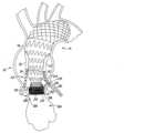
デバイス10を患者の大動脈16にインプラントするにあたり、外科医は、総大腿動脈へ経皮的にアクセスするか、または大腿動脈を露出してアクセスするか、どちらかの方法を取ることが可能である。腸骨動脈または腸骨導管へアクセスしてもよい。当該箇所へアクセスして上行動脈18内に硬質ワイヤを設置した後、デバイス10と送達システムを準備する。図示例においては、送達システムは100cm~105cmの親水性の鞘体から成る。図6に示すように、まず、遠位部品14を送り込む。側面斜位胸部大動脈撮影を行った後、近位フレーム110の遠位端114が無名動脈200の近位に位置するように遠位部品14を配置する。このようにして、導管22の遠位開口170を、無名動脈200に対し、12時および6時の方向になるよう配置することが可能となる。 To implant the
対側性(contralateral)の総大腿動脈ワイヤを用い、遠位部品14の遠位フレーム112を介して、標準的な冠状動脈ガイドカテーテルを各導管22に導入する。ステント24を挿入する前に、導管22にカテーテルを挿管する。代案として、導管22にカテーテルを予め挿管しておいてもよい。カテーテルを用いて、左右の冠状動脈182へアクセス可能となる。図7に示すように、ステント24を遠位開口170から通路164内に進め、導管22の外に出して、冠状動脈182と導管22をつなぐ。このようにして、各動脈182はそれぞれの導管22と接続する。各ステント24は被覆されており、バルーン拡張型ステントもしくは自己拡張型ステントとして具現化されうる。左右の冠状動脈系に冠状動脈バイパス術を行ってから、遠位部品14を設置してもよいことを理解されたい。 A standard coronary guide catheter is introduced into each
近位部品12は、遠位部品14のインプラント完了後に配置されてもよい。近位部品12および遠位部品14の配置は、一日で行われる一度の外科処置で配置してもよいし、または、一回の処置では遠位部品14を配置し、後日、別の処置により近位部品12を配置してもよい。図2に示すように、近位部品12は生来の大動脈弁202をまたぐ位置に配置される。
近位部品12を配置するには、硬質ワイヤを大動脈弁202を通過させて左心室204へ通す。近位部品12を送達するシステムは弁202を通過する。ジュリオ・シー・パルマズ(Julio C. Palmaz)氏による「伸長可能な管腔内移植片及び伸長可能な管腔内移植片を移植するための方法および装置(Expandable Intraluminal Graft, and Method and Apparatus for Implanting an Expandable Intraluminal Graft)」と題された、米国特許第5,102,417号明細書(特許文献1)に送達システムの一例が記載されており、その内容は参照により本明細書に援用される。送達システムを適所に配置後、システムを鞘体から引き出して近位部品12を解放し、それにより自己拡張型フレーム50を拡張させる。上述したように、自己拡張型フレーム50と遠位部品14の近位端102とが係して、近位部品12と遠位部品14とをともに固定されて、近位部品12の遠位端30が遠位部品14内に密閉される。図2に示すように、近位部品12の近位端28は大動脈弁に位置し、砂時計形状を有する近位部品12により、生来の大動脈弁の弁尖用の空間ができるため、弁尖が冠状動脈182の開口に押し付けられたり覆いかぶさったりすることはない。 To deploy the
バルーン拡張型フレーム34は、送達システム内にてバルーンを拡張して配置してもよい。これによりフレーム34は、所定の拡張後直径46へ展開され、血管内を進められて大動脈弁輪210と係合し、大動脈弁輪210をふさぐ。こうして、流体は弁32を介してのみ左心室から流されることとなる。図2に示すように、弁32は、冠状動脈182の近位の大動脈弁輪210に位置する。近位部品12の配置は急速心室ペーシング(rapid ventricular pacing:RVP)中に行ってもよいことは理解されよう。大動脈弁狭窄症である場合は、近位部品12を導入する前に、バルーンを用いた血管形成術により弁32を膨張しておいてもよい。 The balloon
ここで、図8~図16に、デバイス10の近位部品212の別の実施形態を示す。図8~図16に図示した実施形態の一部の要素は、図1~図7の実施形態に関連して上述した要素と実質的に同様である。それらの各要素は、図8~図16においても、図1~図7で用いたものと同じ参照符号を用いて示す。図1~図7の近位部品12と同様、近位部品212は、患者の大動脈16にインプラントした際に遠位部品14に固定することができる。インプラント後は、近位部品212は患者の上行大動脈18内に位置し、遠位部品14は患者の大動脈16の弓部20へ遠位方向に延在する。 8-16, another embodiment of the
図8に示すように、近位部品212は、近位端28から遠位端30まで延在する二重フレーム214を備える。フレーム214は、弁32(透視図にて示す)に取り付けられ、弁32は近位部品212の近位端28に位置する。図示例では、弁32は二尖弁として構成されるが、その他の実施形態では、弁32は三尖弁または四尖弁であってもよいことを理解されたい。弁32は処置済みのウシの心膜、または他の適切な実証済みの生体物質または合成物質から作製することができる。近位部品212を患者の大動脈16にインプラントすると、弁32は大動脈弁に置き換わり、流体(すなわち血液)を心臓から、近位部品212内に延在する通路36へ選択的に通過させる。 As shown in FIG. 8,
近位部品212の二重フレーム214は、自己拡張型外部フレーム216と、該自己拡張型外面フレーム216に固定され、弁32を収容するバルーン拡張型内部フレーム218とを備える。ここで、図9を参照すると、自己拡張型外部フレーム216は、概ね砂時計形状をしており、ニチノール、ステンレススチール、またはインプラント規格を満たす他の金属材料より形成される。その他の実施形態においては、外部フレーム216は高分子材料より形成することができること理解されたい。外部フレーム216は、長尺近位部220、内向きテーパ部222、外向きにテーパした中間部62、および長尺遠位部64を備える。 The
外部フレーム216の長尺近位部220は、近位部品212の近位端28を備え、内向きテーパ部222の近位端226に接続する遠位端224を有する。近位部220は管状のステントとして具現化される。その他の実施形態においては、近位部220は、患者の生体構造に応じて、角柱、円錐、または、他の幾何学形状に成形することができることを理解されたい。 The elongated
図示例においては、近位部220の長さ228は約15mmであり、直径230は約32mmである。その他の実施形態において、フレーム216の寸法は、患者の生体構造に応じて可変であることを理解されたい。以下に詳述するが、図示例においては、直径230は、大動脈弁輪210の直径よりも大きく、近位部品212をインプラントした際に、近位部220と弁輪210との間で締まり嵌めが形成されるようになっている。図9に示すように、近位部220により外部フレーム216内に通路232が画定される。 In the illustrated example,
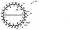
図示例においては、近位部220にはコラーゲン線維234が取り付けられており、弁傍漏出の防止、および大動脈壁内での近位部品212のずれ防止における補助的役割を担っている。線維234には、近位部220から外向きに伸びるものと通路232に向かって内向きに伸びるものがある。その他の実施形態においては、外部フレーム216はヒドロゲルまたは他のシール材料で覆われていてもよいことは理解されよう。別の実施形態においては、複数のかかり(barb)やフックが近位部220に取り付けられていてもよい。フックは、大動脈の組織にさらに係合して、デバイス10のずれを防止できるよう構成することができる。 In the illustrated example,
外部フレーム216の内向きテーパ部222は、近位端226を備え、外向きにテーパした中間部62の近位端68に連結する遠位端236を有する。テーパ部222は、端226と端236との間で内向きにテーパしており、端226における直径は約32mmであり、端236における直径は約22mmである。図示例においては、内向きテーパ部222の長さ238は約10mmである。 The inwardly tapered section 222 of the
自己拡張型フレーム216において外向きにテーパした中間部62は、近位端68と、長尺遠位部64の近位端74に接続する遠位端72とを有する。中間部62は、端68における直径約22mmから端72における直径約28mmまで外向きにテーパする。図示例において、中間部62の長さ76は約10mmであるが、その他の実施形態においては、中間部62の寸法は、例えば、患者の生体構造等に応じて可変とすることができる。 The outwardly tapering
自己拡張型フレーム216の長尺遠位部64は、近位端74から近位部品212の遠位端30まで遠位方向に延在している。図示例においては、遠位部64の長さ78は、テーパ部60および中間部62を組み合わせた長さより長い。一実施例では、長尺遠位部64の長さ78は約30mmであり、直径80は約34mmだが、特にこれに限定されるものではない。その他の実施形態においては、遠位部64の寸法は、例えば、患者の生体構造等に応じて可変とすることができる。ある例示的な実施形態においては、遠位部64は、近位端74と遠位端30との間でテーパしていてもよい。 Elongated
図9に示すように、自己拡張型フレーム216の近位部220と内向きテーパ部222は、オープンセルステント構造を有するよう形成され、また中間部62および遠位部64はZステント構造を有するよう形成される。その他の実施形態では、中間部62、遠位部64、近位部220、テーパ部222は、オープンセルステント構造またはZステント構造を含む、単一構造として形成してもよいことを理解されたい。中間部62、遠位部64、近位部220、テーパ部222はまた、単一のモノリシック部品として形成してもよい。中間部62、遠位部64、テーパ部222の外表面240を、低収縮ポリエステル、延伸多孔質PTFE(ePTFE)、または非多孔質被覆材料242で被覆して、流体の外表面240への透過を防止することができる。近位部220に対して直接遠位(immediately distal)である被覆材料242には、「トラップドア(trap door)86」を設け、万一傍弁漏出が起こった場合には、これを開放して、塞栓を行うための1つ以上の手術器具を通過させることができる。中間部62、遠位部64、テーパ部222の外表面240を、低収縮性ダクロンまたはその他の合成材料により被覆してもよい。フレーム216の一部または全体を、ヒドロゲルまたはその他のシール材で被膜することができることも理解されたい。 As shown in FIG. 9,
上述のように、二重フレーム214の外部フレーム216は、バルーン拡張型内部フレーム218に固定され、該内部フレーム218は、通路232内に位置する。図10に示すように、フレーム218内には弁32を収容する。バルーン拡張型フレーム218として、バルーン拡張型管状ステント244を例示でき、その長さ246は約15mmである。その他の実施形態では、ステント244の長さは、例えば、患者の生体構造等に応じて、それより長くても短くてもよい。ステント244は管状であり、ニチノール、ステンレススチール、またはインプラント規格を満たす他の金属材料によりオープンセル(open-cell)構造で構築される。その他の実施形態では、ステント244を高分子材料から形成し、例えば、Zステント構造として形成してもよいことを理解されたい。図示例では、ステント244の外表面248を、流体の外表面248への透過を防止可能することのできる、低収縮ポリエステル、延伸多孔質PTFE(ePTFE)、または非多孔質被覆材料250で被覆する。しかしながら、標準的なポリエステル、延伸多孔質PTFE(ePTFE)または他の非多孔質材料で、ステント244を被覆してもよいことを理解されたい。 As mentioned above, the
図10に示すように、内部フレーム218のステント244は直径252を有する。以下に詳述するが、バルーン拡張型フレーム218は、インプラント中に、未拡張直径(図示せず)から拡張直径252へ拡張可能である。図示例においては、内部フレーム218を拡張した際の拡張直径252は約26mmである。その他の実施形態においては、拡張直径は、外部フレーム216の近位部220の直径230以上であってもよい。以下に詳述するが、図示例においては、拡張後直径252は、大動脈弁輪210の直径よりも大きく作られており、近位部品212をインプラントして内部フレーム218を拡張した際に、近位部220と弁輪210との間で締まり嵌めが形成されるようになっている。 As shown in FIG. 10,
ここで図11を参照すると、二重フレーム部品214の内部フレーム218は複数の縫い目260を介して外部フレーム216に固定されている。その他の実施形態においては、溶接または他の締め具により、内部フレーム218を外部フレーム216に固定してもよいことを理解されたい。図11~図14に示すように、内部フレーム218と弁部品32は、自己拡張型フレーム216内に画定した通路232内に位置する。内部フレーム218が拡張していないときは、ステント244の外表面248は、外部フレーム216に取り付けられた線維234から離間している。図示例においては、間隙264がその間に画定され、その間隙264の大きさは約2mmから約3mmである。 Referring now to FIG. 11,
図14に示すように、バルーン拡張型内部フレーム218は、矢印266で示した方向に拡張できる。上述のように、外部フレーム216の近位部220の直径230は、大動脈弁輪210の直径よりも大きい。よって、近位部品212をインプラントすると、近位部220は弁輪210の直径サイズまで収縮する。ステント244の拡張直径252は弁輪の直径よりも大きいため、ステント244の外表面248は、被覆材250を介して線維234(すなわち、外部フレーム216の近位部220の内表面)に係合する。そのようにして間隙264が閉じ、線維234と被覆材250により、内部フレーム218と外部フレーム216との間が密閉される。 As shown in FIG. 14, balloon expandable
近位部品212を備えたエンドグラフトデバイス10を患者の大動脈16にインプラントするにあたり、外科医は、総大腿動脈へ経皮的にアクセスするか、または大腿動脈を露出してアクセスするか、どちらかの方法を取ることが可能である。そして外科医は、図1~図7を参照して上述した方法で遠位部品14をインプラントし、動脈182内位置へステント24を進める。遠位部品14のインプラント後に、近位部品212を配置してもよい。そうするには、大動脈弁202を介して硬質ワイヤを左心室204内へ通す。そして、弁202を介して近位部品212用の送達システムを通過させる。 In implanting the
送達システムを適所に配置後、システムを鞘体から引き出して近位部品12を解放し、それにより自己拡張型フレーム216を拡張させる。自己拡張型フレーム216と、遠位部品14の近位端102とが係合して、近位部品212と遠位部品14とが一体固定され、近位部品212の遠位端30が遠位部品14内に密閉される。 After the delivery system is in place, the system is withdrawn from the sheath to release
フレーム216を鞘体から引き出すと、近位部220が拡張して大動脈弁輪210と係合し、フレーム216と弁輪210間に締まり嵌めが形成され、デバイス10が適所に固定される。図15に示すように、外部フレーム216内の内部フレーム218は、最初は、未拡張状態にある。バルーン構造を拡張して内部フレーム218を配置することができる。バルーン拡張内部フレーム218が拡張すると、該内部フレーム218は外部フレーム216と係合し、それにより外部フレーム216のコラーゲン線維被覆/ヒドロゲル被覆された近位部220が大動脈弁輪210に押しつけられる。図16に示すように、フレーム216とフレーム218が一体係合することにより、弁輪210と弁傍領域とを密閉して、弁傍漏出を防止できる。よって、流体は、近位部品212の弁32のみを介して左心室204から送られてくる。図15~図16に示すように、弁32は、冠状動脈182の近位の大動脈弁輪210に位置する。急速心室ペーシング(rapid ventricular pacing:RVP)中に近位部品212を配置しもよいことを理解されたい。大動脈弁狭窄症である場合は、近位部品212を導入する前に、バルーンを用いた血管形成術により弁32を膨張していてもよい。 As the
上記の各実施形態において、近位部品12、212の自己拡張型フレーム部により、デバイス10を配置する際の精度および制御を大幅に改善することができる。弁32を二尖弁構造としたことで、次の3つの目的をそれぞれ達成可能である。すなわち、(1)弁交連の数を2つに減らすことによりプロファイルを低くすることができ、(2)弁32をより高度に大動脈弁輪に適合させることができ、(3)弁輪が非対称である場合、大動脈弁閉鎖不全症の発生率を減らすことができる。 In each of the above embodiments, the self-expanding frame portion of the
ここで、図17~図22を参照すると、近位部品12または近位部品212に多少の変更を加えることで、経カテーテル弁として用いることできる。以下に詳述するように、そのような弁は大腿動脈経路または腋窩動脈経路に配置することができる。 17-22, with minor modifications to
図17~図19に、経カテーテル弁部品312の一実施形態を示す。図17~図19に図示した実施形態の一部の要素は、図1~図7の近位部品12に関連して上述した要素と実質的に同様である。それらの各要素は、図17~図19においても、図1~図7で用いたものと同じ参照符号を用いて示す。図1~図7の近位部品12と同様、経カテーテル弁部品312は、近位端28から遠位端30まで延在するフレーム26を備える。フレーム326は、弁32(透視図にて示す)に取り付けられ、弁32は、弁部品312の近位端28に位置する。弁部品312を患者の大動脈16にインプラントすると、弁32は大動脈弁に置き換わり、心臓から弁部品312中に延在する通路36へ選択的に流体(血液)を流す。 One embodiment of a
弁32は、フレーム26のバルーン拡張型フレーム34内に収容される。図17に示すように、バルーン拡張型フレーム34として、経カテーテル弁部品312の近位端28から遠位方向に延在するバルーン拡張ステント38を例示することができ、その長さ40は約15mmである。その他の実施形態においては、例えば、患者の生体構造等に応じて、ステント38はそれより長くても短くてもよい。ステント38は管状であり、ニチノール、ステンレススチール、またはインプラント規格を満たすその他の金属材料によりオープンセル(open-cell)構造で構築される。その他の実施形態では、ステント38は高分子材料から形成され、例えば、Zステント構造として形成することができることを理解されたい。図示例では、ステント38の外表面42は、流体の外表面42への透過を防止することのできる、低収縮ポリエステル、延伸多孔質PTFE(ePTFE)、または非多孔質被覆材料44で被覆する。しかしながら、標準的なポリエステル、延伸多孔質PTFE(ePTFE)、または他の非多孔性材料でステント38を被覆してもよいことを理解されたい。
図17に示すように、バルーン拡張型フレーム34のステント38は直径46を有しており、以下に詳述するが、インプラント中、未拡張直径(図示せず)から拡張直径46へ拡張可能である。図示例においては、フレーム34が拡張した際にはその直径46は約26mmである。その他の実施形態では、拡張直径は、例えば、患者の生体構造等に応じてより、26mmより大きくても小さくてもよい。図示例において、直径46は、大動脈弁輪210の直径よりも大きく、経カテーテル弁部品312をインプラントすると、ステント38と弁輪210との間で締まり嵌めが形成される。 As shown in FIG. 17, the stent 38 of the balloon
バルーン拡張型フレーム34は自己拡張型フレーム350に取り付けられる。図示例では、フレーム34とフレーム350をともに縫合することにより、バルーン拡張型フレーム34の遠位端52がフレーム350の近位端54に固定され、経カテーテル弁部品312のフレーム26を形成している。その他の実施形態において、フレーム34とフレーム350は、溶接または他の締め具を介して固定されてもよいことを理解されたい。フレーム34とフレーム350は、また、単一のモノリシックなフレームとして形成してもよい。 Balloon
図17に示すように、自己拡張型フレーム350は、概ね砂時計形状をしており、ニチノール、ステンレススチール、またはインプラント規格を満たすその他の金属材料より形成される。その別の実施形態において、フレーム350を高分子材料より形成してもよいことを理解されたい。フレーム350は、内向きにテーパした近位部360、外向きにテーパした中間部62、および長尺な遠位部64を備える。近位部360は、フレーム350の近位端54を含み、外向きにテーパした中間部62の近位端68に連結する遠位端66を有する。近位部360は、端54と端66との間で内向きにテーパしており、端54における直径は約26mmであり、端66における直径は約22mmである。図示例においては、近位部360の長さ70は約15mmである。 As shown in FIG. 17, the self-expanding
自己拡張型フレーム350において外向きにテーパした中間部62は、近位端68、および長尺な遠位部64の近位端74に連結する遠位端72を有する。中間部62は、端68における直径約22mmから端72における直径約28mmまで外向きにテーパしている。図示例において、中間部62の長さ76は約10mmであるが、その他の実施形態においては、中間部62の寸法は、例えば、患者の生体構造等に応じて可変でありうる。 The outwardly tapering
自己拡張型フレーム350における長尺遠位部64は、近位端74から、弁部品312の遠位端30まで遠位方向に延在する。図示例においては、遠位部64の長さ78は、テーパ部60、62を組み合わせた長さよりも長い。一実施例においては、長尺遠位部64の長さ78は約30mmであり、その直径80は約34mmであるが、特にこれに限定されない。その他の実施形態においては、遠位部64の寸法は、例えば、患者の生体構造等に応じて可変とすることができる。一例示的な実施形態においては、遠位部64は、近位端74と遠位端30との間でテーパしていてもよい。 Elongated
図17に示すように、自己拡張型フレーム350の近位部360は、オープンセルステント構造を有するよう形成され、また中間部62および遠位部64はZステント構造を有するよう形成される。その他の実施形態では、近位部360、中間部62、遠位部64は、オープンセルステント構造、メッシュ状ステント構造、またはZステント構造を含む、単一構造として形成することができことを理解されたい。近位部360、中間部62、遠位部64はまた、単一のモノリシック部品として形成してもよい。 As shown in Figure 17, the
図17に示すように、フレーム350の近位部360の外表面314は被覆されておらず、流体が開口318を介して透過可能としている。中間部62と遠位部64の外表面316は、低収縮ポリエステル、延伸多孔質PTFE(ePTFE)、または非多孔性被覆材料84で被覆して、流体の外表面320への透過を防止できる。弁部品312の外表面320は、低収縮性ダクロンまたは他の合成材料により被覆してもよい。非被覆であるオープンセルステント部360は、冠状動脈の灌流が可能なよう構成する。被覆部62、64は、大動脈18に対して弁部品312を固定する働きをし、上行大動脈の拡張または開窓型グラフト/分枝弓グラフトが行われる際には、ドッキングステーションを提供する。また、被覆部62、64は、STジャンクションの拡大のない、Bタイプ動脈瘤に適した弁部品312におけるエンドグラフト拡張も可能となる。 As shown in FIG. 17, the
経カテーテル弁部品312の送達は、生来の大動脈弁をまたいで左心室へアクセスすることから開始することができる。上行大動脈造影を行って左右冠状動脈の位置を特定してもよい。ガイドワイヤを備えるOTW導入システム(over the wire introducer system)を用いて、弁部品312を大動脈18に導入する。腸骨大腿動脈、鎖骨下動脈、または頸動脈を介してガイドワイヤを左心室204に設置した後、総大腿動脈を介して弁部品312を送り込み、生来の大動脈弁202をまたいで通過させてもよい。図18~図19に示すように、血管造影を行い冠状動脈182の位置を突き止めた後、送達システムを鞘体から引き出して弁部品312を解放し、自己拡張型フレーム350が拡張する。 Delivery of the
ここで、バルーン拡張型フレーム34は、送達システム内でバルーンを膨張させてから配置してもよい。図18~図19に示すように、これにより、フレーム34は、所定の拡張直径46へ展開され、血管内を進められて大動脈弁輪210と係合し、大動脈弁輪210を密閉する。こうして、流体は弁32のみを介して左心室から流れることになり、弁32は、冠状動脈182の近位の大動脈弁輪210に位置することとなる。弁部品312の非被覆部360が開口318を有するため、冠状動脈182へ血液を流すことが可能となり、血液循環が促進される。弁部品312の配置は急速心室ペーシング(rapid ventricular pacing:RVP)中に行ってもよいことを理解されたい。 Here, the balloon
次に図20~図22に、経カテーテル弁部品(以下、弁部品412)の別の実施形態を示す。図20~図22に図示される実施形態の一部の要素は、図8~図16の近位部品212について上述した要素と実質的に同様である。それらの各要素は、図20~図22においても、図8~図16で用いたものと同じ参照符号を用いて示す。図8~図16の近位部品212と同様、弁部品412は、近位端28から遠位端30へ延在する二重フレーム414を備える。フレーム414は、弁32(透視図にて示す)に取り付けられ、弁32は、部品412の近位端28に位置する。図示例においては、弁32は二尖弁として構成される。弁部品412を患者の大動脈16にインプラントすると、弁32は大動脈弁に置き換わり、流体(血液)を、心臓から弁部品412内に延在する通路36へ選択的に通過させる。 20-22, another embodiment of a transcatheter valve component (hereinafter valve component 412) is shown. Some elements of the embodiments illustrated in FIGS. 20-22 are substantially similar to those described above for the
二重フレーム414は、自己拡張型外部フレーム416と、自己拡張型外部フレーム416に固定され弁32を収容するバルーン拡張型内部フレーム218を備える。図20を参照すると、自己拡張型外部フレーム416は、概ね砂時計形状をしており、ニチノール、ステンレススチール、またはインプラント規格を満たす他の金属材料より形成される。その他の実施形態において、外部フレーム416は高分子材料より形成してもよいことを理解されたい。外部フレーム416は、長尺近位部220、内向きテーパ部422、外向きにテーパした中間部62、および長尺遠位部64を備える。 Dual frame 414 comprises a self-expanding
外部フレーム416の長尺近位部220は、部品412の近位端28を含み、内向きテーパ部222の近位端226に連結する遠位端224を有する。近位部220は管状のステントとして具現化される。その他の実施形態においては、近位部220は、例えば、患者の生体構造に応じて、角柱、円錐、または、他の幾何学形状に成形することができることを理解されたい。 An elongated
図示例において、近位部220の長さ228は約15mmであり、その直径230は約32mmである。その他の実施形態においては、フレーム416の寸法は、患者の生体構造に応じて可変であることを理解されたい。以下に詳述するが、図示例においては、直径230は大動脈弁輪210の直径より大きい寸法で作られており、弁部品412をインプラントした際には、近位部220と弁輪210との間で締まり嵌めが形成される。図20に示すように、近位部220は外部フレーム416内に通路232を画定している。 In the illustrated example, the
図示例においては、近位部220にはコラーゲン線維234が取り付けられており、弁傍漏出の防止、および大動脈壁内での弁部品412のずれ防止において補助的役割を担っている。線維234には、近位部220から外向きへ伸びるものと通路232に向かって内向きに伸びるものがある。別の実施形態においては、外部フレーム216はヒドロゲルまたはその他のシール材料で覆われていてもよいことも理解されよう。その他の実施形態においては、複数のかかり(barb)やフックを近位部220に取り付けてもよい。フックは、大動脈の組織にさらに係合して、デバイス10のずれを防止するよう構成することができる。 In the illustrated example,
外部フレーム416の内向きテーパ部422は、近位端226と、外向きにテーパした中間部62の近位端68に連結する遠位端236とを備える。テーパ部422は、端226と端236との間で内向きにテーパしており、端226における直径は約32mmであり、端236における約22mmである。図示例においては、内向きテーパ部422の長さ238は約10mmである。 Inwardly tapered
自己拡張型フレーム416において外向きにテーパした中間部62は、近位端68と、長尺遠位部64の近位端74に接続する遠位端72とを有する。中間部62は、端68における直径約22mmから端72における直径約28mmまで外向きにテーパする。図示例において、中間部62の長さ76は約10mmであるが、その他実施形態においては、中間部62の寸法は、例えば、患者の生体構造等に応じて可変とすることができる。 The outwardly tapering
自己拡張型フレーム416の長尺な遠位部64は、近位端74から部品412の遠位端30まで遠位方向に延在する。図示例においては、遠位部64は長さ78を有しており、その長さはテーパ部60および中間部62を組み合わせた長さより長い。一実施例では、長尺遠位部64の長さ78は約30mmであり、直径80は約34mmだが、特にこれに限定されない。その他の実施形態においては、遠位部64の寸法は、例えば、患者の生体構造等に応じて可変とすることができる。ある例示的な実施形態においては、遠位部64は近位端74と遠位端30との間でテーパしていてもよい。 Elongated
図20に示すように、自己拡張型フレーム416の近位部220と内向きテーパ部422は、オープンセルステント構造を有するよう形成され、また中間部62および遠位部64はZステント構造を有するよう形成される。その他の実施形態では、中間部62、遠位部64、近位部220、テーパ部422は、オープンセルステント構造、メッシュ状ステント構造、またはZステント構造を含む、単一構造として形成してもよいことを理解されたい。中間部62、遠位部64、近位部220、テーパ部422は、また、単一のモノリシック部品として形成してもよい。中間部62、遠位部64の各外表面440を、低収縮ポリエステル、延伸多孔質PTFE(ePTFE)、または他の非多孔質被覆材料442で被覆して、流体の表面440への透過を防止できる。テーパ部422の外表面444は被覆せず、流体は表面444により画定された開口446を介して透過可能である。被覆部62、64は、大動脈18に対して弁部品312を固定する働きをし、上行大動脈の拡張または開窓型グラフト/分枝弓グラフトが行われる際には、ドッキングステーションを提供する。 As shown in FIG. 20, the
上述のように、二重フレーム414の外部フレーム416は、バルーン拡張型内部フレーム218に固定され、バルーン拡張型内部フレーム218は、通路232内に位置して弁32を収容する。上述のように、バルーン拡張型フレーム218は、インプラント中、未拡張直径450から拡張直径(図示せず)へ拡張可能である。 As described above, the
弁部品412を配置する際は、大動脈弁202を介して硬質ワイヤを左心室204内へ通す。その後、弁202を介して、弁部品412のための送達システムを通過させる。送達システムを適所に配置後、送達システムを鞘体から引き出して弁部品412を解放し、それにより自己拡張型フレーム416を拡張させる。フレーム416の近位部220が拡張して大動脈弁輪210と係合することで、フレーム416と弁輪210間に締まり嵌めが形成され、弁部品412を適所に固定することが可能となる。図21に示すように、外部フレーム416内の内部フレーム218は、最初は、未拡張状態にある。バルーン構造を拡張することにより内部フレーム218を配置することができる。バルーン拡張型内部フレーム218が拡張すると、該内部フレーム218は外部フレーム416と係合し、外部フレーム416のコラーゲン線維被覆/ヒドロゲル被覆された近位部220は大動脈弁輪210に押し付けられる。 A rigid wire is threaded through the
図22に示すように、フレーム218とフレーム416が一体係合することにより、弁輪210と弁傍領域とを密閉して、弁傍漏出を防止できる。よって、流体は、左心室204から部品412の弁32のみを介して送られてくる。弁部品412における非被覆部422に設けた開口446により、冠状動脈182へ血液を流すことができ、血液循環が促進される。 As shown in FIG. 22, the integral engagement of
部品12、14、212および経カテーテル弁312、412の設計は、機能不全の状態に陥った場合のことも意図的に考慮しており、そのような機能不全を補正することも想定していることを理解されたい。例えば、部品12、14、212は、弁傍漏出を補正可能である。より具体的には、弁傍漏出(Ia型エンドリーク)については、弁32付近での漏出がIa型エンドリークとして作用する。部品12、312のトラップドア86を通して、漏出領域のコイル塞栓術が可能になる。180度の位置にある2つのトラップドアを介して、大動脈弁輪より上の領域全体へアクセス可能となる。冠状動脈182は遠位部品14内の導管22により保護されているため、この領域においてコイル塞栓術を行っても冠状動脈の血流を阻害することはない。臨床的には、弁傍漏出のコイル塞栓術は、心臓弁手術後に弁付近でさらに漏出があった場合、既に行われている。 The design of the
インプラント後の大動脈弁閉鎖不全症(AI)もまた補正可能である。経カテーテル弁のインプラント後、重大なAIが17%以下の患者に発生することが確認されている。弁輪の深刻な石灰化を除いて、現在の三尖弁形態および大動脈弁輪の卵型が、AIの原因となる弁膜の接合不全を引き起こす。本明細書で論じた設計の二尖弁の特質により、接合不全およびそれに続くAIの問題をなくすことが可能となる。 Post-implant aortic regurgitation (AI) can also be corrected. It has been determined that significant AI occurs in up to 17% of patients after transcatheter valve implantation. Except for severe calcification of the annulus, the current tricuspid valve morphology and the oval shape of the aortic annulus cause the mal-coaptation of the valve leaflets that cause AI. The bicuspid nature of the design discussed herein allows for the elimination of malcoaptation and subsequent AI problems.
構造的な弁の変質もまた補正可能である。より具体的には、二尖弁に設計することで、弁の流体領域を阻害することなく、第1の経カテーテル弁をまたいで、もうひとつ別の経カテーテル弁を設置することが可能となる。 Structural valve degeneration can also be corrected. More specifically, the bicuspid valve design allows placement of a second transcatheter valve across the first transcatheter valve without disturbing the fluid field of the valve. .
冠不全もまた補正可能である。部品14のテーパ部128と連結しているエンドカブロル導管22は途切れることなく冠動脈に血流を流す。最初に部品14を配置することにより、外科医はカブロル導管22を介して作業可能となり、標準的なカテーテルとガイドワイヤを用いて左右冠動脈に挿管可能となる。冠状動脈からカブロル導管22の間にはステント24を配置する。冠状動脈への血流の流れを確認してから、部品12または部品212を配置する場合もある。テーパ状に設計されていることにより、冠状動脈ステントが、デバイス10と大動脈壁間で締め付けられるリスクを緩和することができる。 Coronary insufficiency can also be corrected.
経カテーテル弁312、412の場合も、傍弁漏出を補正可能である。弁の中間部360、422はオープンセル構造であるため、必要に応じて冠動脈保護を行った後、冠状動脈への挿管およびステント配置を行い、漏出に対しコイル塞栓術を施すことが可能である。
経カテーテル弁312、412内の構造的な弁の変質も補正可能である。二尖弁に設計することで、弁の流体領域を阻害することなく、第1の経カテーテル弁をまたいで、もうひとつ別の経カテーテル弁を設置することが可能となる。 Structural valvular alterations within the
二重フレーム部品は、例えばプロテーゼ僧帽弁や三尖弁等、他の経カテーテル弁置換デバイスとしての形態をとる場合もある。二重フレーム部品はまた、血管内デバイスのシーリングゾーンの向上に用いられ、腹部動脈瘤や胸部動脈瘤の処置、および末梢血管疾患の処置に用いられてもよい。 Dual frame components may also take the form of other transcatheter valve replacement devices, such as prosthetic mitral and tricuspid valves. Dual frame components are also used to improve the sealing zone of endovascular devices and may be used to treat abdominal and thoracic aneurysms and to treat peripheral vascular disease.
本明細書に記載のデバイスや方法は広範囲にわたって適用可能なことが理解されよう。前述の各実施形態は、その方法および装置の原理、およびその実用的な応用例のいくつかを説明する目的で選択し、説明したものである。先行する記載により、他の当業者は、考えられる特定の利用に適合する範囲で様々な修正を加えつつ、様々な実施形態で該方法および装置を利用可能となる。特許法の規定にしたがって、本開示の実施の原則および方式を、例示的な実施形態として説明および例示した。 It will be appreciated that the devices and methods described herein have broad applicability. The foregoing embodiments were chosen and described for the purpose of illustrating the principles of the method and apparatus and some of its practical applications. The foregoing description will enable those skilled in the art to utilize the method and apparatus in various embodiments with various modifications adapted to the particular uses envisioned. In accordance with the provisions of the patent statutes, the principles and modes of practice of this disclosure have been explained and illustrated in exemplary embodiments.
本発明の方法および装置の範囲は、以下の特許請求の範囲により規定することが意図される。しかしながら、本開示は、本発明の精神または範囲から逸脱しない範囲で、具体的に説明、例示したものとは別のやり方で実践してもよいことを理解すべきである。当業者であれば、特許請求の範囲に記載の内容を実施する際、以下の特許請求の範囲に規定される精神または範囲から逸脱しない範囲で、本明細書に記載の実施形態のさまざまな変更例が利用可能であることは理解すべきである。 It is intended that the scope of the method and apparatus of the invention be defined by the following claims. However, it is to be understood that the present disclosure may be practiced otherwise than as specifically described and illustrated without departing from the spirit or scope of the invention. Various modifications of the embodiments described herein will occur to those skilled in the art without departing from the spirit or scope as defined in the following claims when implementing the claimed subject matter. It should be appreciated that examples are available.
本開示の範囲は、上記記載を参照するのではなく、添付の特許請求の範囲に与えられる最大限の権利範囲における均等物も合わせて、添付の特許請求の範囲を参照して画定されるべきである。本明細書で論じられた技術分野においては、将来的な発展があることが予見、意図されるため、開示されたシステムおよび方法はそのような将来的な例に組み込まれるであろう。さらに特許請求の範囲で用いられるすべての用語は、本明細書中で明白にそうでないとの表明がない限り、当業者により理解されるそれら用語の持つ最も広い正当な解釈および通常の意味が与えられることを意図する。特に、単数形(「a」、「the」、「said」等)が用いられた際は、特許請求の範囲内でそれとは逆であるとの明白な限定がない限り、その記載された要素は1つ以上であると解釈されるべきである。以下に記す特許請求の範囲は、開示の範囲を規定し、よってその特許請求の範囲内およびその均等物である方法および装置が範囲に含まれることが意図される。要約すると、本開示は変形および改変可能であり、以下の特許請求の範囲によってのみ限定されるということが理解されるべきである。 The scope of the present disclosure should be determined with reference to the appended claims, along with equivalents to the fullest extent of the rights to which such claims are entitled, rather than with reference to the foregoing description. is. Future developments in the technical fields discussed herein are foreseen and intended, and the disclosed systems and methods will be incorporated into such future examples. Moreover, all terms used in the claims are to be given their broadest reasonable interpretation and ordinary meaning as understood by those of ordinary skill in the art, unless expressly stated otherwise herein. intended to be In particular, when the singular form (“a,” “the,” “said,” etc.) is used, the recited element shall refer to the recited element unless there is an express limitation to the contrary in the claims. should be interpreted as being one or more. It is intended that the following claims define the scope of the disclosure and that methods and apparatus within the scope of these claims and their equivalents be covered. In summary, it should be understood that the present disclosure is susceptible to variations and modifications and is limited only by the following claims.
Claims (4)
Translated fromJapanese金属材料から形成された外部フレームと、
弁を収容する内部フレームと、を備え、
前記内部フレームは、高分子材料から形成された管状ステントを形成しており、
前記内部フレームは、複数の縫い目によって前記外部フレームに固定されており、
少なくとも前記外部フレームの近位部には、線維が取り付けられており、
前記線維は、弁傍漏出を防止する構成となっており、
前記線維は、前記外部フレームの前記近位部から外向きに伸びている、
大動脈血管内修復用であり且つ大腿動脈経路を通じて配置されるための経カテーテル大動脈弁デバイス。A transcatheter aortic valve device for aortic endovascular repair and for placement through the femoral artery pathway, comprising:
an outer frame formed from a metallic material;
an internal frame housing the valve;
said internal frame forming a tubular stent formed from a polymeric material;
wherein the inner frame is secured to the outer frame by a plurality of seams;
fibers attached to at least a proximal portion of the outer frame;
The fibers are configured to prevent paravalvular leakage,
said fibers extending outwardly from said proximal portion of said outer frame;
A transcatheter aortic valve device for aortic endovascular repair and for placement through the femoral artery pathway.
請求項1に記載の大動脈血管内修復用であり且つ大腿動脈経路を通じて配置されるための経カテーテル大動脈弁デバイス。The fibers are configured to form a seal between the inner frame and the outer frame when the device is implanted in the aortic annulus.
A transcatheter aortic valve device for aortic endovascular repair of claim 1 and for placement through the femoral artery pathway.
請求項2に記載の大動脈血管内修復用であり且つ大腿動脈経路を通じて配置されるための経カテーテル大動脈弁デバイス。When the device is implanted in the aortic annulus, the fibers are configured to compress against the aortic annulus to seal the aortic annulus and prevent paravalvular leakage.
3. A transcatheter aortic valve device for aortic endovascular repair of claim 2 and for placement through the femoral artery pathway.
請求項1に記載の大動脈血管内修復用であり且つ大腿動脈経路を通じて配置されるための経カテーテル大動脈弁デバイス。the external frame has an open cell structure,
A transcatheter aortic valve device for aortic endovascular repair of claim 1 and for placement through the femoral artery pathway.
Applications Claiming Priority (5)
| Application Number | Priority Date | Filing Date | Title |
|---|---|---|---|
| US201161567458P | 2011-12-06 | 2011-12-06 | |
| US61/567,458 | 2011-12-06 | ||
| US201261723446P | 2012-11-07 | 2012-11-07 | |
| US61/723,446 | 2012-11-07 | ||
| JP2020122656AJP7041205B2 (en) | 2011-12-06 | 2020-07-17 | Intravascular aortic repair device and how to use it |
Related Parent Applications (1)
| Application Number | Title | Priority Date | Filing Date |
|---|---|---|---|
| JP2020122656ADivisionJP7041205B2 (en) | 2011-12-06 | 2020-07-17 | Intravascular aortic repair device and how to use it |
Publications (2)
| Publication Number | Publication Date |
|---|---|
| JP2022069539A JP2022069539A (en) | 2022-05-11 |
| JP7219833B2true JP7219833B2 (en) | 2023-02-08 |
Family
ID=48524550
Family Applications (5)
| Application Number | Title | Priority Date | Filing Date |
|---|---|---|---|
| JP2014546060AActiveJP6129867B2 (en) | 2011-12-06 | 2012-12-06 | Intravascular aortic repair device and method of use thereof |
| JP2017078010AActiveJP6431122B2 (en) | 2011-12-06 | 2017-04-11 | Intravascular aortic repair device and method of use thereof |
| JP2018206631AActiveJP6738392B2 (en) | 2011-12-06 | 2018-11-01 | Intravascular aortic repair device and method of using the same |
| JP2020122656AActiveJP7041205B2 (en) | 2011-12-06 | 2020-07-17 | Intravascular aortic repair device and how to use it |
| JP2022037195AActiveJP7219833B2 (en) | 2011-12-06 | 2022-03-10 | Devices for endovascular aortic repair and methods of use thereof |
Family Applications Before (4)
| Application Number | Title | Priority Date | Filing Date |
|---|---|---|---|
| JP2014546060AActiveJP6129867B2 (en) | 2011-12-06 | 2012-12-06 | Intravascular aortic repair device and method of use thereof |
| JP2017078010AActiveJP6431122B2 (en) | 2011-12-06 | 2017-04-11 | Intravascular aortic repair device and method of use thereof |
| JP2018206631AActiveJP6738392B2 (en) | 2011-12-06 | 2018-11-01 | Intravascular aortic repair device and method of using the same |
| JP2020122656AActiveJP7041205B2 (en) | 2011-12-06 | 2020-07-17 | Intravascular aortic repair device and how to use it |
Country Status (8)
| Country | Link |
|---|---|
| US (33) | US8940040B2 (en) |
| EP (5) | EP3656354B1 (en) |
| JP (5) | JP6129867B2 (en) |
| CN (1) | CN103945793B (en) |
| CA (7) | CA3095731C (en) |
| DE (1) | DE202012013754U1 (en) |
| ES (1) | ES2678209T3 (en) |
| WO (1) | WO2013086132A1 (en) |
Families Citing this family (150)
| Publication number | Priority date | Publication date | Assignee | Title |
|---|---|---|---|---|
| GB0419954D0 (en) | 2004-09-08 | 2004-10-13 | Advotek Medical Devices Ltd | System for directing therapy |
| CN2817768Y (en)* | 2005-05-24 | 2006-09-20 | 微创医疗器械(上海)有限公司 | Tectorium stand and host cage section thereof |
| US20130190676A1 (en) | 2006-04-20 | 2013-07-25 | Limflow Gmbh | Devices and methods for fluid flow through body passages |
| EP3443938B1 (en) | 2007-09-26 | 2024-01-24 | St. Jude Medical, LLC | Collapsible prosthetic heart valves |
| US9532868B2 (en) | 2007-09-28 | 2017-01-03 | St. Jude Medical, Inc. | Collapsible-expandable prosthetic heart valves with structures for clamping native tissue |
| EP2815724B2 (en) | 2008-07-15 | 2024-03-13 | St. Jude Medical, Inc. | Collapsible and re-expandable prosthetic heart valve cuff designs and complementary technological applications |
| AU2010218384B2 (en) | 2009-02-27 | 2014-11-20 | St. Jude Medical, Inc. | Stent features for collapsible prosthetic heart valves |
| US8579964B2 (en) | 2010-05-05 | 2013-11-12 | Neovasc Inc. | Transcatheter mitral valve prosthesis |
| US9308087B2 (en) | 2011-04-28 | 2016-04-12 | Neovasc Tiara Inc. | Sequentially deployed transcatheter mitral valve prosthesis |
| US9554897B2 (en) | 2011-04-28 | 2017-01-31 | Neovasc Tiara Inc. | Methods and apparatus for engaging a valve prosthesis with tissue |
| JP6227542B2 (en) | 2011-11-11 | 2017-11-08 | ボルトン メディカル インコーポレイテッド | Universal endovascular graft |
| CN106420107B (en) | 2011-11-16 | 2019-02-05 | 波顿医疗公司 | The device and method of reparation for aortic branch blood vessel |
| CN103945793B (en) | 2011-12-06 | 2016-05-04 | 俄奥梯科创新有限公司 | For device and the using method thereof of repairing in aorta lumen |
| US20130274873A1 (en) | 2012-03-22 | 2013-10-17 | Symetis Sa | Transcatheter Stent-Valves and Methods, Systems and Devices for Addressing Para-Valve Leakage |
| US11207176B2 (en) | 2012-03-22 | 2021-12-28 | Boston Scientific Scimed, Inc. | Transcatheter stent-valves and methods, systems and devices for addressing para-valve leakage |
| US9345573B2 (en) | 2012-05-30 | 2016-05-24 | Neovasc Tiara Inc. | Methods and apparatus for loading a prosthesis onto a delivery system |
| US9585748B2 (en) | 2012-09-25 | 2017-03-07 | Edwards Lifesciences Corporation | Methods for replacing a native heart valve and aorta with a prosthetic heart valve and conduit |
| US10835367B2 (en) | 2013-03-08 | 2020-11-17 | Limflow Gmbh | Devices for fluid flow through body passages |
| CA2898879C (en) | 2013-03-08 | 2023-05-02 | Limflow Gmbh | Methods and systems for providing or maintaining fluid flow through body passages |
| US9339274B2 (en) | 2013-03-12 | 2016-05-17 | St. Jude Medical, Cardiology Division, Inc. | Paravalvular leak occlusion device for self-expanding heart valves |
| EP2967849B1 (en) | 2013-03-12 | 2025-08-13 | St. Jude Medical, Cardiology Division, Inc. | Self-actuating sealing portions for paravalvular leak protection |
| US10271949B2 (en) | 2013-03-12 | 2019-04-30 | St. Jude Medical, Cardiology Division, Inc. | Paravalvular leak occlusion device for self-expanding heart valves |
| US9398951B2 (en) | 2013-03-12 | 2016-07-26 | St. Jude Medical, Cardiology Division, Inc. | Self-actuating sealing portions for paravalvular leak protection |
| US9326856B2 (en) | 2013-03-14 | 2016-05-03 | St. Jude Medical, Cardiology Division, Inc. | Cuff configurations for prosthetic heart valve |
| CN107714240B (en)* | 2013-03-15 | 2021-04-02 | 西美蒂斯股份公司 | Improvements relating to transcatheter stent-valves |
| US9572665B2 (en) | 2013-04-04 | 2017-02-21 | Neovasc Tiara Inc. | Methods and apparatus for delivering a prosthetic valve to a beating heart |
| US10034784B2 (en)* | 2013-04-17 | 2018-07-31 | Gilbert H. L. Tang | Heart valve and endovascular graft components and method for delivery |
| WO2014204807A1 (en) | 2013-06-19 | 2014-12-24 | Aga Medical Corporation | Collapsible valve having paravalvular leak protection |
| US10117742B2 (en) | 2013-09-12 | 2018-11-06 | St. Jude Medical, Cardiology Division, Inc. | Stent designs for prosthetic heart valves |
| US9913715B2 (en) | 2013-11-06 | 2018-03-13 | St. Jude Medical, Cardiology Division, Inc. | Paravalvular leak sealing mechanism |
| EP2870946B1 (en) | 2013-11-06 | 2018-10-31 | St. Jude Medical, Cardiology Division, Inc. | Paravalvular leak sealing mechanism |
| EP4176844B1 (en) | 2013-11-06 | 2025-08-20 | St. Jude Medical, Cardiology Division, Inc. | Reduced profile prosthetic heart valve |
| WO2015077274A1 (en) | 2013-11-19 | 2015-05-28 | St. Jude Medical, Cardiology Division, Inc. | Sealing structures for paravalvular leak protection |
| US9820852B2 (en) | 2014-01-24 | 2017-11-21 | St. Jude Medical, Cardiology Division, Inc. | Stationary intra-annular halo designs for paravalvular leak (PVL) reduction—active channel filling cuff designs |
| US20150209141A1 (en) | 2014-01-24 | 2015-07-30 | St. Jude Medical, Cardiology Division, Inc. | Stationary intra-annular halo designs for paravalvular leak (pvl) reduction-passive channel filling cuff designs |
| US9980832B2 (en)* | 2014-01-28 | 2018-05-29 | Sanford Health | Pararenal and thoracic arch stent graft and methods for use |
| US8998971B1 (en) | 2014-01-28 | 2015-04-07 | Sanford Health | Pararenal stent graft and methods for use |
| WO2015126712A1 (en) | 2014-02-18 | 2015-08-27 | St. Jude Medical, Cardiology Division, Inc. | Bowed runners for paravalvular leak protection |
| EP3122289A1 (en) | 2014-03-26 | 2017-02-01 | St. Jude Medical, Cardiology Division, Inc. | Transcatheter mitral valve stent frames |
| WO2015152980A1 (en) | 2014-03-31 | 2015-10-08 | St. Jude Medical, Cardiology Division, Inc. | Paravalvular sealing via extended cuff mechanisms |
| EP3142604B1 (en) | 2014-05-16 | 2024-01-10 | St. Jude Medical, Cardiology Division, Inc. | Transcatheter valve with paravalvular leak sealing ring |
| WO2015173646A1 (en) | 2014-05-16 | 2015-11-19 | Veosource Sa | Implantable self-cleaning blood filters |
| ES2795358T3 (en) | 2014-05-16 | 2020-11-23 | St Jude Medical Cardiology Div Inc | Subannular sealing for paravalvular leak protection |
| US9757230B2 (en) | 2014-05-16 | 2017-09-12 | St. Jude Medical, Cardiology Division, Inc. | Stent assembly for use in prosthetic heart valves |
| US9545263B2 (en) | 2014-06-19 | 2017-01-17 | Limflow Gmbh | Devices and methods for treating lower extremity vasculature |
| US10667931B2 (en)* | 2014-07-20 | 2020-06-02 | Restore Medical Ltd. | Pulmonary artery implant apparatus and methods of use thereof |
| BR112017005790A2 (en) | 2014-09-23 | 2018-01-30 | Bolton Medical Inc | vascular repair devices and methods of use |
| PL3653177T3 (en) | 2015-01-11 | 2022-01-31 | Ascyrus Medical, Llc | Hybrid device for surgical aortic repair |
| EP3250157B1 (en)* | 2015-01-28 | 2024-08-28 | Aortic Innovations, LLC | Modular endo-aortic device |
| US20160235525A1 (en)* | 2015-02-12 | 2016-08-18 | Medtronic, Inc. | Integrated valve assembly and method of delivering and deploying an integrated valve assembly |
| US9962260B2 (en) | 2015-03-24 | 2018-05-08 | St. Jude Medical, Cardiology Division, Inc. | Prosthetic mitral valve |
| US10405965B2 (en) | 2015-03-25 | 2019-09-10 | Sanford Health | Pararenal and thoracic arch stent graft and methods for use |
| EP3078350B1 (en)* | 2015-04-09 | 2018-01-31 | Frid Mind Technologies | 3d filter for prevention of stroke |
| KR101672448B1 (en) | 2015-05-18 | 2016-11-03 | 삼성중공업 주식회사 | Sampling apparatus for drilling mud |
| EP3310305B1 (en)* | 2015-06-18 | 2022-05-25 | Ascyrus Medical, LLC | Branched aortic graft |
| US20170056151A1 (en)* | 2015-08-26 | 2017-03-02 | Cook Medical Technologies Llc | Endograft with one or more apertures |
| US20170056215A1 (en) | 2015-09-01 | 2017-03-02 | Medtronic, Inc. | Stent assemblies including passages to provide blood flow to coronary arteries and methods of delivering and deploying such stent assemblies |
| WO2017105986A1 (en)* | 2015-12-14 | 2017-06-22 | The Cleveland Clinic Foundation | Apparatus for repairing the function of a diseased valve and method for making the apparatus |
| CA3007660A1 (en) | 2015-12-15 | 2017-06-22 | Neovasc Tiara Inc. | Transseptal delivery system |
| US11833034B2 (en) | 2016-01-13 | 2023-12-05 | Shifamed Holdings, Llc | Prosthetic cardiac valve devices, systems, and methods |
| BR112018014262A2 (en)* | 2016-01-14 | 2018-12-18 | Cardiatis Sa | implantable endoluminal prosthesis |
| US10433952B2 (en) | 2016-01-29 | 2019-10-08 | Neovasc Tiara Inc. | Prosthetic valve for avoiding obstruction of outflow |
| US10363130B2 (en) | 2016-02-05 | 2019-07-30 | Edwards Lifesciences Corporation | Devices and systems for docking a heart valve |
| US10070950B2 (en)* | 2016-02-09 | 2018-09-11 | Medtronic Vascular, Inc. | Endoluminal prosthetic assemblies, and associated systems and methods for percutaneous repair of a vascular tissue defect |
| US10130465B2 (en) | 2016-02-23 | 2018-11-20 | Abbott Cardiovascular Systems Inc. | Bifurcated tubular graft for treating tricuspid regurgitation |
| CN105662654A (en)* | 2016-02-25 | 2016-06-15 | 复旦大学附属中山医院 | Coronary artery protecting device |
| ES2830748T3 (en) | 2016-04-05 | 2021-06-04 | Bolton Medical Inc | Stent grafting with internal tunnels and fenestrations |
| ES2905193T3 (en) | 2016-05-25 | 2022-04-07 | Bolton Medical Inc | Stent grafts for the treatment of aneurysms |
| WO2018005969A1 (en)* | 2016-06-30 | 2018-01-04 | Washington University | Device and method of inhibiting endoleaks |
| WO2018026904A1 (en) | 2016-08-03 | 2018-02-08 | Spence Paul A | Devices, systems and methods to improve placement and prevent heart block with percutaneous aortic valve replacement |
| US10548722B2 (en) | 2016-08-26 | 2020-02-04 | St. Jude Medical, Cardiology Division, Inc. | Prosthetic heart valve with paravalvular leak mitigation features |
| GB201615219D0 (en) | 2016-09-07 | 2016-10-19 | Vascutek Ltd And Univ Medical Center Hamburg-Eppendorf (Uke) | Hybrid prosthesis and delivery system |
| US10456249B2 (en) | 2016-09-15 | 2019-10-29 | St. Jude Medical, Cardiology Division, Inc. | Prosthetic heart valve with paravalvular leak mitigation features |
| US11771434B2 (en) | 2016-09-28 | 2023-10-03 | Restore Medical Ltd. | Artery medical apparatus and methods of use thereof |
| US10292851B2 (en) | 2016-09-30 | 2019-05-21 | DePuy Synthes Products, Inc. | Self-expanding device delivery apparatus with dual function bump |
| GB2554670B (en) | 2016-09-30 | 2022-01-05 | Vascutek Ltd | A vascular graft |
| EP3531977B1 (en) | 2016-10-28 | 2024-06-26 | St. Jude Medical, Cardiology Division, Inc. | Prosthetic mitral valve |
| CA3042588A1 (en) | 2016-11-21 | 2018-05-24 | Neovasc Tiara Inc. | Methods and systems for rapid retraction of a transcatheter heart valve delivery system |
| US11583383B2 (en)* | 2016-12-28 | 2023-02-21 | Lifetech Scientific (Shenzhen) Co. Ltd. | Luminal stent |
| US11185406B2 (en)* | 2017-01-23 | 2021-11-30 | Edwards Lifesciences Corporation | Covered prosthetic heart valve |
| USD867595S1 (en) | 2017-02-01 | 2019-11-19 | Edwards Lifesciences Corporation | Stent |
| IT201700031905A1 (en)* | 2017-03-23 | 2018-09-23 | Enrico Riccardo Ferrari | Aortic endoprosthesis. |
| EP3600169A4 (en) | 2017-03-24 | 2020-12-30 | Ascyrus Medical, LLC | Multi-spiral self-expanding stent and methods of making and using the same |
| EP3609415B1 (en) | 2017-04-10 | 2023-08-23 | LimFlow GmbH | Devices for treating lower extremity vasculature |
| US11331179B2 (en) | 2017-04-24 | 2022-05-17 | Endologix Llc | Endovascular systems, devices, and methods allowing for branch device placement in channel of main graft |
| US11471278B2 (en)* | 2017-05-02 | 2022-10-18 | Braile Biomédica Indústria, Comércio E Representaç | Valved endoprosthesis releasing device and valved endoprosthesis |
| GB2562065A (en) | 2017-05-02 | 2018-11-07 | Vascutek Ltd | Endoprosthesis |
| USD889653S1 (en) | 2017-05-15 | 2020-07-07 | St. Jude Medical, Cardiology Division, Inc. | Stent having tapered struts |
| USD875250S1 (en) | 2017-05-15 | 2020-02-11 | St. Jude Medical, Cardiology Division, Inc. | Stent having tapered aortic struts |
| USD875935S1 (en) | 2017-05-15 | 2020-02-18 | St. Jude Medical, Cardiology Division, Inc. | Stent having tapered struts |
| GB201707929D0 (en) | 2017-05-17 | 2017-06-28 | Vascutek Ltd | Tubular medical device |
| US12064341B2 (en) | 2017-05-31 | 2024-08-20 | Edwards Lifesciences Corporation | Sealing member for prosthetic heart valve |
| WO2018225059A1 (en) | 2017-06-05 | 2018-12-13 | Restore Medical Ltd | Double walled fixed length stent like apparatus and methods of use thereof |
| CN116196149A (en)* | 2017-06-30 | 2023-06-02 | 爱德华兹生命科学公司 | Transcatheter valve docking station |
| EP4397285A3 (en) | 2017-06-30 | 2024-09-25 | Edwards Lifesciences Corporation | Lock and release mechanisms for trans-catheter implantable devices |
| US10709544B2 (en) | 2017-07-19 | 2020-07-14 | Cook Medical Technologies Llc | Non-cylindrical variable pitch mesh top stent |
| US10709543B2 (en) | 2017-07-19 | 2020-07-14 | Cook Medical Technologies Llc | Non-cylindrical mesh top stent with twisted sections |
| US20200237496A1 (en)* | 2017-07-25 | 2020-07-30 | KHOYNEZHAD, Ali | Endovascular replacement of aortic valve, aortic root, and ascending aorta |
| WO2019032992A2 (en)* | 2017-08-11 | 2019-02-14 | Edwards Lifesciences Corportion | Sealing element for prosthetic heart valve |
| CA3073834A1 (en) | 2017-08-25 | 2019-02-28 | Neovasc Tiara Inc. | Sequentially deployed transcatheter mitral valve prosthesis |
| GB201715658D0 (en)* | 2017-09-27 | 2017-11-08 | Vascutek Ltd | An endoluminal device |
| DE102017123461A1 (en) | 2017-10-10 | 2019-04-11 | Jotec Gmbh | Expandable vascular implant |
| US11382751B2 (en) | 2017-10-24 | 2022-07-12 | St. Jude Medical, Cardiology Division, Inc. | Self-expandable filler for mitigating paravalvular leak |
| CN109984861B (en)* | 2017-12-29 | 2025-03-07 | 杭州唯强医疗科技有限公司 | Covered stents for interventional treatment of abdominal aortic disease |
| WO2019152058A1 (en) | 2018-02-02 | 2019-08-08 | W.L.Gore & Associates, Inc. | Delivery system aid and associated systems and methods |
| US11872146B2 (en)* | 2018-03-23 | 2024-01-16 | Sanford Health | Aortic filter and flow diverter and methods for use thereof |
| US11813413B2 (en) | 2018-03-27 | 2023-11-14 | St. Jude Medical, Cardiology Division, Inc. | Radiopaque outer cuff for transcatheter valve |
| US11166832B2 (en)* | 2018-06-19 | 2021-11-09 | Medtronic Vascular, Inc. | Re-location of main body bypass branch on multi-branched stent graft |
| US10456280B1 (en)* | 2018-08-06 | 2019-10-29 | DePuy Synthes Products, Inc. | Systems and methods of using a braided implant |
| AU2019325548B2 (en) | 2018-08-21 | 2025-06-26 | Shifamed Holdings, Llc | Prosthetic cardiac valve devices, systems, and methods |
| CN109172043B (en)* | 2018-09-12 | 2020-11-10 | 于存涛 | Dissected proximate ascending aortic stent anchored by innominate artery and delivery system |
| WO2020060828A1 (en) | 2018-09-20 | 2020-03-26 | St. Jude Medical, Cardiology Division, Inc. | Attachment of leaflets to prosthetic heart valve |
| CN113260337A (en) | 2018-10-05 | 2021-08-13 | 施菲姆德控股有限责任公司 | Prosthetic heart valve devices, systems, and methods |
| SG11202102500UA (en) | 2018-10-09 | 2021-04-29 | Limflow Gmbh | Devices and methods for catheter alignment |
| US11364117B2 (en) | 2018-10-15 | 2022-06-21 | St. Jude Medical, Cardiology Division, Inc. | Braid connections for prosthetic heart valves |
| CN113056302B (en) | 2018-10-19 | 2023-03-28 | 施菲姆德控股有限责任公司 | Adjustable medical device |
| CN113271890B (en) | 2018-11-08 | 2024-08-30 | 内奥瓦斯克迪亚拉公司 | Ventricular deployment of transcatheter mitral valve prosthesis |
| US11471277B2 (en) | 2018-12-10 | 2022-10-18 | St. Jude Medical, Cardiology Division, Inc. | Prosthetic tricuspid valve replacement design |
| CN109730805B (en)* | 2018-12-17 | 2021-07-20 | 深圳市先健畅通医疗有限公司 | Branch type blood vessel support |
| GB201820898D0 (en) | 2018-12-20 | 2019-02-06 | Vascutek Ltd | Stent device |
| EP3902503B1 (en) | 2018-12-26 | 2025-01-29 | St. Jude Medical, Cardiology Division, Inc. | Elevated outer cuff for reducing paravalvular leakage and increasing stent fatigue life |
| CA3132873A1 (en) | 2019-03-08 | 2020-09-17 | Neovasc Tiara Inc. | Retrievable prosthesis delivery system |
| EP3941391B1 (en) | 2019-03-19 | 2024-12-04 | Shifamed Holdings, LLC | Prosthetic cardiac valve devices, systems |
| FI3941392T3 (en) | 2019-03-20 | 2025-07-28 | Inqb8 Medical Tech Llc | Aortic dissection implant |
| CA3135753C (en) | 2019-04-01 | 2023-10-24 | Neovasc Tiara Inc. | Controllably deployable prosthetic valve |
| US11491006B2 (en) | 2019-04-10 | 2022-11-08 | Neovasc Tiara Inc. | Prosthetic valve with natural blood flow |
| US20220211481A1 (en)* | 2019-04-22 | 2022-07-07 | Eolo Medical Inc. | Devices for the treatment of pulmonary disorders with implantable valves |
| US11779742B2 (en) | 2019-05-20 | 2023-10-10 | Neovasc Tiara Inc. | Introducer with hemostasis mechanism |
| CN110063824A (en)* | 2019-06-10 | 2019-07-30 | 郑州美港高科生物科技有限公司 | A kind of vertebral artery stent |
| JP7520897B2 (en) | 2019-06-20 | 2024-07-23 | ニオバスク ティアラ インコーポレイテッド | Thin prosthetic mitral valve |
| EP3763330A1 (en)* | 2019-07-10 | 2021-01-13 | P+F Cardiovascular GmbH | Implant, delivery device and method of delivering an implant |
| GB2587013A (en)* | 2019-09-13 | 2021-03-17 | Tevar Pty Ltd | Inflatable dilatation device |
| EP3795096A1 (en)* | 2019-09-19 | 2021-03-24 | Kardiozis SAS | Endoprosthesis and a method of producing an endoprosthesis |
| EP4051174A4 (en) | 2019-11-01 | 2023-11-22 | LimFlow GmbH | Devices and methods for increasing blood perfusion to a distal extremity |
| US11911268B1 (en)* | 2020-02-20 | 2024-02-27 | Aortic Innovations, Llc | Transcatheter device for endovascular aortic repair and method of using the same |
| JP7729784B2 (en)* | 2020-04-03 | 2025-08-26 | エドワーズ ライフサイエンシーズ コーポレイション | Multilayer covering for prosthetic heart valves |
| EP4149388A4 (en)* | 2020-05-12 | 2024-06-05 | TT3A S.r.l. | METHOD AND DEVICE FOR TRANSCATHETER TREATMENT OF ASCENDING AORTA ANEURYSM |
| FR3110385B1 (en)* | 2020-05-20 | 2025-07-11 | Fond Hopital St Joseph | Aortic root replacement device |
| US11944557B2 (en)* | 2020-08-31 | 2024-04-02 | Boston Scientific Scimed, Inc. | Self expanding stent with covering |
| CN116456937A (en) | 2020-08-31 | 2023-07-18 | 施菲姆德控股有限责任公司 | Prosthetic Valve Delivery System |
| CA3193742A1 (en)* | 2020-09-03 | 2022-03-10 | inQB8 Medical Technologies, LLC | Delivery systems and methods for prosthetic heart valve |
| US12329635B2 (en) | 2020-12-04 | 2025-06-17 | Shifamed Holdings, Llc | Flared prosthetic cardiac valve delivery devices and systems |
| US12201521B2 (en) | 2021-03-22 | 2025-01-21 | Shifamed Holdings, Llc | Anchor position verification for prosthetic cardiac valve devices |
| WO2023281599A1 (en)* | 2021-07-05 | 2023-01-12 | 日本ライフライン株式会社 | Treatment apparatus |
| US11324583B1 (en) | 2021-07-06 | 2022-05-10 | Archo Medical LTDA | Multi-lumen stent-graft and related surgical methods |
| CN113813091B (en)* | 2021-09-18 | 2023-04-25 | 复旦大学附属中山医院青浦分院 | Support for reconstructing branch artery of aortic arch part in aortic arch intracavity repair operation |
| CN114081675B (en)* | 2021-09-28 | 2023-11-21 | 四川大学华西医院 | transcatheter aortic valve replacement assist device |
| WO2024013525A1 (en)* | 2022-07-13 | 2024-01-18 | Skardoutsos Spyridon | Aortic wall reinforcing system |
| WO2025006678A1 (en)* | 2023-06-28 | 2025-01-02 | Edwards Lifesciences Corporation | Prosthetic heart valves for deployment to a mitral valve |
| WO2025165817A1 (en) | 2024-01-30 | 2025-08-07 | Edwards Lifesciences Corporation | Conformal surgical heart valve sewing rings |
Citations (2)
| Publication number | Priority date | Publication date | Assignee | Title |
|---|---|---|---|---|
| US20060276813A1 (en) | 2005-05-20 | 2006-12-07 | The Cleveland Clinic Foundation | Apparatus and methods for repairing the function of a diseased valve and method for making same |
| WO2011143263A2 (en) | 2010-05-10 | 2011-11-17 | Heart Leaflet Technologies, Inc. | Stentless support structure |
Family Cites Families (260)
| Publication number | Priority date | Publication date | Assignee | Title |
|---|---|---|---|---|
| US3002816A (en) | 1958-07-23 | 1961-10-03 | Kellogg M W Co | Method of effecting exothermic catalytic reactions |
| US3365728A (en) | 1964-12-18 | 1968-01-30 | Edwards Lab Inc | Upholstered heart valve having a sealing ring adapted for dispensing medicaments |
| US3725961A (en) | 1970-12-29 | 1973-04-10 | Baxter Laboratories Inc | Prosthetic heart valve having fabric suturing element |
| US3878565A (en) | 1971-07-14 | 1975-04-22 | Providence Hospital | Vascular prosthesis with external pile surface |
| US4047252A (en) | 1976-01-29 | 1977-09-13 | Meadox Medicals, Inc. | Double-velour synthetic vascular graft |
| US4164046A (en) | 1977-05-16 | 1979-08-14 | Cooley Denton | Valve prosthesis |
| US6221102B1 (en) | 1983-12-09 | 2001-04-24 | Endovascular Technologies, Inc. | Intraluminal grafting system |
| US7166125B1 (en) | 1988-03-09 | 2007-01-23 | Endovascular Technologies, Inc. | Intraluminal grafting system |
| US5102417A (en) | 1985-11-07 | 1992-04-07 | Expandable Grafts Partnership | Expandable intraluminal graft, and method and apparatus for implanting an expandable intraluminal graft |
| SE453258B (en) | 1986-04-21 | 1988-01-25 | Medinvent Sa | ELASTIC, SELF-EXPANDING PROTEST AND PROCEDURE FOR ITS MANUFACTURING |
| US4892539A (en) | 1988-02-08 | 1990-01-09 | D-R Medical Systems, Inc. | Vascular graft |
| US6004346A (en) | 1990-02-28 | 1999-12-21 | Medtronic, Inc. | Intralumenal drug eluting prosthesis |
| US5411552A (en) | 1990-05-18 | 1995-05-02 | Andersen; Henning R. | Valve prothesis for implantation in the body and a catheter for implanting such valve prothesis |
| DK124690D0 (en) | 1990-05-18 | 1990-05-18 | Henning Rud Andersen | FAT PROTECTION FOR IMPLEMENTATION IN THE BODY FOR REPLACEMENT OF NATURAL FLEET AND CATS FOR USE IN IMPLEMENTING A SUCH FAT PROTECTION |
| US5366504A (en) | 1992-05-20 | 1994-11-22 | Boston Scientific Corporation | Tubular medical prosthesis |
| EP0958795A3 (en) | 1993-08-20 | 2001-04-04 | Kanji Inoue | Appliance to be implanted and device for introducing the collapsed appliance into a catheter |
| US5609627A (en) | 1994-02-09 | 1997-03-11 | Boston Scientific Technology, Inc. | Method for delivering a bifurcated endoluminal prosthesis |
| US6165213A (en)* | 1994-02-09 | 2000-12-26 | Boston Scientific Technology, Inc. | System and method for assembling an endoluminal prosthesis |
| DE4418336A1 (en) | 1994-05-26 | 1995-11-30 | Angiomed Ag | Stent for widening and holding open receptacles |
| US5397355A (en) | 1994-07-19 | 1995-03-14 | Stentco, Inc. | Intraluminal stent |
| US5683449A (en) | 1995-02-24 | 1997-11-04 | Marcade; Jean Paul | Modular bifurcated intraluminal grafts and methods for delivering and assembling same |
| US6193745B1 (en) | 1995-10-03 | 2001-02-27 | Medtronic, Inc. | Modular intraluminal prosteheses construction and methods |
| US5824037A (en) | 1995-10-03 | 1998-10-20 | Medtronic, Inc. | Modular intraluminal prostheses construction and methods |
| US5665117A (en) | 1995-11-27 | 1997-09-09 | Rhodes; Valentine J. | Endovascular prosthesis with improved sealing means for aneurysmal arterial disease and method of use |
| US6878161B2 (en) | 1996-01-05 | 2005-04-12 | Medtronic Vascular, Inc. | Stent graft loading and deployment device and method |
| US5718159A (en) | 1996-04-30 | 1998-02-17 | Schneider (Usa) Inc. | Process for manufacturing three-dimensional braided covered stent |
| EP0850607A1 (en) | 1996-12-31 | 1998-07-01 | Cordis Corporation | Valve prosthesis for implantation in body channels |
| US5957974A (en) | 1997-01-23 | 1999-09-28 | Schneider (Usa) Inc | Stent graft with braided polymeric sleeve |
| US5957949A (en) | 1997-05-01 | 1999-09-28 | World Medical Manufacturing Corp. | Percutaneous placement valve stent |
| US20020032405A1 (en)* | 1998-10-15 | 2002-03-14 | Sweezer William P. | Arterial perfusion cannula and method for providing cardiopulmonary bypass |
| DE19857887B4 (en) | 1998-12-15 | 2005-05-04 | Fraunhofer-Gesellschaft zur Förderung der angewandten Forschung e.V. | Anchoring support for a heart valve prosthesis |
| US6896690B1 (en) | 2000-01-27 | 2005-05-24 | Viacor, Inc. | Cardiac valve procedure methods and devices |
| US7018401B1 (en) | 1999-02-01 | 2006-03-28 | Board Of Regents, The University Of Texas System | Woven intravascular devices and methods for making the same and apparatus for delivery of the same |
| US6258117B1 (en) | 1999-04-15 | 2001-07-10 | Mayo Foundation For Medical Education And Research | Multi-section stent |
| US8257428B2 (en) | 1999-08-09 | 2012-09-04 | Cardiokinetix, Inc. | System for improving cardiac function |
| US6334868B1 (en) | 1999-10-08 | 2002-01-01 | Advanced Cardiovascular Systems, Inc. | Stent cover |
| US7074235B1 (en) | 1999-10-16 | 2006-07-11 | Sumit Roy | Low-profile, non-stented prosthesis for transluminal implantation |
| US8016877B2 (en) | 1999-11-17 | 2011-09-13 | Medtronic Corevalve Llc | Prosthetic valve for transluminal delivery |
| US8579966B2 (en) | 1999-11-17 | 2013-11-12 | Medtronic Corevalve Llc | Prosthetic valve for transluminal delivery |
| US6458153B1 (en) | 1999-12-31 | 2002-10-01 | Abps Venture One, Ltd. | Endoluminal cardiac and venous valve prostheses and methods of manufacture and delivery thereof |
| US6663667B2 (en) | 1999-12-29 | 2003-12-16 | Edwards Lifesciences Corporation | Towel graft means for enhancing tissue ingrowth in vascular grafts |
| US6821297B2 (en) | 2000-02-02 | 2004-11-23 | Robert V. Snyders | Artificial heart valve, implantation instrument and method therefor |
| AU2001241909A1 (en) | 2000-03-03 | 2001-09-17 | Timothy A.M. Chuter | Large vessel stents and occluders |
| US6814752B1 (en) | 2000-03-03 | 2004-11-09 | Endovascular Technologies, Inc. | Modular grafting system and method |
| US8092511B2 (en) | 2000-03-03 | 2012-01-10 | Endovascular Technologies, Inc. | Modular stent-graft for endovascular repair of aortic arch aneurysms and dissections |
| US6454799B1 (en) | 2000-04-06 | 2002-09-24 | Edwards Lifesciences Corporation | Minimally-invasive heart valves and methods of use |
| US6729356B1 (en) | 2000-04-27 | 2004-05-04 | Endovascular Technologies, Inc. | Endovascular graft for providing a seal with vasculature |
| IL136213A0 (en) | 2000-05-17 | 2001-05-20 | Xtent Medical Inc | Selectively expandable and releasable stent |
| US20020082684A1 (en) | 2000-09-25 | 2002-06-27 | David Mishaly | Intravascular prosthetic and method |
| US6254632B1 (en) | 2000-09-28 | 2001-07-03 | Advanced Cardiovascular Systems, Inc. | Implantable medical device having protruding surface structures for drug delivery and cover attachment |
| US6547820B1 (en) | 2000-10-03 | 2003-04-15 | Scimed Life Systems, Inc. | High profile fabric graft for arteriovenous access |
| WO2002035988A2 (en) | 2000-10-31 | 2002-05-10 | Prodesco, Inc. | Graft having region for biological seal formation |
| US6482228B1 (en) | 2000-11-14 | 2002-11-19 | Troy R. Norred | Percutaneous aortic valve replacement |
| BE1013757A6 (en) | 2000-12-12 | 2002-07-02 | Frid Noureddine | Luminal endoprosthesis MODULAR. |
| AUPR217300A0 (en)* | 2000-12-20 | 2001-01-25 | Ketharanathan, Vettivetpillai | Method of creating biological and biosynthetic material for implantation |
| DE10065824B4 (en) | 2000-12-28 | 2018-10-31 | Jotec Gmbh | Endovascular stent for implantation in the ascending branch of the aorta |
| US20010044650A1 (en) | 2001-01-12 | 2001-11-22 | Simso Eric J. | Stent for in-stent restenosis |
| US6752829B2 (en) | 2001-01-30 | 2004-06-22 | Scimed Life Systems, Inc. | Stent with channel(s) for containing and delivering a biologically active material and method for manufacturing the same |
| US6733525B2 (en) | 2001-03-23 | 2004-05-11 | Edwards Lifesciences Corporation | Rolled minimally-invasive heart valves and methods of use |
| WO2002076346A1 (en) | 2001-03-23 | 2002-10-03 | Hassan Tehrani | Branched aortic arch stent graft |
| ES2223759T3 (en) | 2001-03-27 | 2005-03-01 | William Cook Europe Aps | AORTIC GRAFT DEVICE. |
| FR2826863B1 (en)* | 2001-07-04 | 2003-09-26 | Jacques Seguin | ASSEMBLY FOR PLACING A PROSTHETIC VALVE IN A BODY CONDUIT |
| FR2827502B1 (en) | 2001-07-17 | 2004-04-09 | Univ Joseph Fourier | MICROMUSCLE IN A BIOLOGICAL ENVIRONMENT |
| US6893460B2 (en) | 2001-10-11 | 2005-05-17 | Percutaneous Valve Technologies Inc. | Implantable prosthetic valve |
| US20090112303A1 (en) | 2001-11-28 | 2009-04-30 | Lee Bolduc | Devices, systems, and methods for endovascular staple and/or prosthesis delivery and implantation |
| US7294146B2 (en) | 2001-12-03 | 2007-11-13 | Xtent, Inc. | Apparatus and methods for delivery of variable length stents |
| AUPR961701A0 (en) | 2001-12-19 | 2002-01-24 | Cook Incorporated | Improving graft adhesion |
| US7018404B2 (en) | 2002-01-24 | 2006-03-28 | St. Jude Medical, Inc. | Conduit for aorta or pulmonary artery replacement |
| EP1487380B1 (en) | 2002-03-25 | 2008-02-27 | Cook Incorporated | Branched vessel prothesis |
| US6918926B2 (en) | 2002-04-25 | 2005-07-19 | Medtronic Vascular, Inc. | System for transrenal/intraostial fixation of endovascular prosthesis |
| US20030204249A1 (en) | 2002-04-25 | 2003-10-30 | Michel Letort | Endovascular stent graft and fixation cuff |
| US7270675B2 (en) | 2002-05-10 | 2007-09-18 | Cordis Corporation | Method of forming a tubular membrane on a structural frame |
| US7044962B2 (en) | 2002-06-25 | 2006-05-16 | Scimed Life Systems, Inc. | Implantable prosthesis with displaceable skirt |
| US7175652B2 (en) | 2002-08-20 | 2007-02-13 | Cook Incorporated | Stent graft with improved proximal end |
| US7550004B2 (en) | 2002-08-20 | 2009-06-23 | Cook Biotech Incorporated | Endoluminal device with extracellular matrix material and methods |
| GB0220340D0 (en) | 2002-09-02 | 2002-10-09 | Anson Medical Ltd | Flexible stent-graft |
| CN1723048A (en) | 2002-10-11 | 2006-01-18 | 卡蒂菲西尔公司 | Medical device comprising a bio-compatible polymeric product with a layered structure |
| DE60326000D1 (en) | 2002-12-04 | 2009-03-12 | Cook Inc | METHOD AND DEVICE FOR TREATMENT IN AORTASE ACTION |
| US7399315B2 (en)* | 2003-03-18 | 2008-07-15 | Edwards Lifescience Corporation | Minimally-invasive heart valve with cusp positioners |
| EP1608293B1 (en) | 2003-04-03 | 2015-06-03 | Cook Medical Technologies LLC | Deployment system for a branched stent graft |
| US20040243221A1 (en) | 2003-05-27 | 2004-12-02 | Fawzi Natalie V. | Endovascular graft including substructure for positioning and sealing within vasculature |
| DE10334868B4 (en) | 2003-07-29 | 2013-10-17 | Pfm Medical Ag | Implantable device as a replacement organ valve, its manufacturing process and basic body and membrane element for it |
| US8500792B2 (en) | 2003-09-03 | 2013-08-06 | Bolton Medical, Inc. | Dual capture device for stent graft delivery system and method for capturing a stent graft |
| US20070219613A1 (en) | 2003-10-06 | 2007-09-20 | Xtent, Inc. | Apparatus and methods for interlocking stent segments |
| US9579194B2 (en) | 2003-10-06 | 2017-02-28 | Medtronic ATS Medical, Inc. | Anchoring structure with concave landing zone |
| JP4627978B2 (en) | 2003-10-27 | 2011-02-09 | 泰晴 野一色 | Low blood permeability medical material |
| US7144421B2 (en)* | 2003-11-06 | 2006-12-05 | Carpenter Judith T | Endovascular prosthesis, system and method |
| US7740656B2 (en) | 2003-11-17 | 2010-06-22 | Medtronic, Inc. | Implantable heart valve prosthetic devices having intrinsically conductive polymers |
| US7261732B2 (en) | 2003-12-22 | 2007-08-28 | Henri Justino | Stent mounted valve |
| EP2529699B1 (en)* | 2003-12-23 | 2014-01-29 | Sadra Medical, Inc. | Repositionable heart valve |
| US8840663B2 (en) | 2003-12-23 | 2014-09-23 | Sadra Medical, Inc. | Repositionable heart valve method |
| US7381219B2 (en) | 2003-12-23 | 2008-06-03 | Sadra Medical, Inc. | Low profile heart valve and delivery system |
| US7780725B2 (en) | 2004-06-16 | 2010-08-24 | Sadra Medical, Inc. | Everting heart valve |
| CN101897989B (en) | 2004-02-23 | 2013-11-13 | 洛马林达大学医学中心 | Hemostatic agent for topical and internal use |
| US20050197687A1 (en) | 2004-03-02 | 2005-09-08 | Masoud Molaei | Medical devices including metallic films and methods for making same |
| DE102004012351A1 (en) | 2004-03-11 | 2005-09-29 | pfm Produkte für die Medizin AG | Device for recanalizing a cavity, organ or vessel |
| US7323006B2 (en)* | 2004-03-30 | 2008-01-29 | Xtent, Inc. | Rapid exchange interventional devices and methods |
| EP1737389B1 (en) | 2004-04-12 | 2019-07-24 | Cook Medical Technologies LLC | Stent graft repair device |
| US7682381B2 (en) | 2004-04-23 | 2010-03-23 | Boston Scientific Scimed, Inc. | Composite medical textile material and implantable devices made therefrom |
| BRPI0510107A (en) | 2004-04-23 | 2007-09-25 | 3F Therapeutics Inc | implantable protein valve |
| CA2563426C (en) | 2004-05-05 | 2013-12-24 | Direct Flow Medical, Inc. | Unstented heart valve with formed in place support structure |
| WO2005112821A2 (en)* | 2004-05-20 | 2005-12-01 | Med Institute, Inc. | Enhanced biological fixation of grafts |
| CA2565106C (en) | 2004-05-25 | 2013-11-05 | Chestnut Medical Technologies, Inc. | Flexible vascular occluding device |
| US8617234B2 (en) | 2004-05-25 | 2013-12-31 | Covidien Lp | Flexible vascular occluding device |
| US20060206200A1 (en) | 2004-05-25 | 2006-09-14 | Chestnut Medical Technologies, Inc. | Flexible vascular occluding device |
| US8623067B2 (en) | 2004-05-25 | 2014-01-07 | Covidien Lp | Methods and apparatus for luminal stenting |
| US7276078B2 (en)* | 2004-06-30 | 2007-10-02 | Edwards Lifesciences Pvt | Paravalvular leak detection, sealing, and prevention |
| WO2006010130A1 (en) | 2004-07-09 | 2006-01-26 | University Of Florida Research Foundation, Inc. | Tubular polymer stent coverings |
| US8481074B2 (en) | 2004-07-16 | 2013-07-09 | Poly-Med, Inc. | Hemostatic microfibrous constructs |
| DE602005023033D1 (en) | 2004-09-21 | 2010-09-30 | Cook Inc | STENT GRAFT CONNECTION ARRANGEMENT |
| AU2004324043A1 (en) | 2004-10-02 | 2006-04-20 | Christoph Hans Huber | Methods and devices for repair or replacement of heart valves or adjacent tissue without the need for full cardiopulmonary support |
| US8128680B2 (en) | 2005-01-10 | 2012-03-06 | Taheri Laduca Llc | Apparatus and method for deploying an implantable device within the body |
| US20060155366A1 (en) | 2005-01-10 | 2006-07-13 | Laduca Robert | Apparatus and method for deploying an implantable device within the body |
| US7306623B2 (en) | 2005-01-13 | 2007-12-11 | Medtronic Vascular, Inc. | Branch vessel graft design and deployment method |
| EP1838247A4 (en) | 2005-01-21 | 2009-06-10 | Innovia Llc | Stent-valve and deployment catheter for use therewith |
| US20060195183A1 (en) | 2005-02-18 | 2006-08-31 | The Cleveland Clinic Foundation | Apparatus and methods for replacing a cardiac valve |
| US8025694B2 (en) | 2005-02-25 | 2011-09-27 | Abbott Laboratories Vascular Enterprises Limited | Modular vascular prosthesis and methods of use |
| US7914569B2 (en)* | 2005-05-13 | 2011-03-29 | Medtronics Corevalve Llc | Heart valve prosthesis and methods of manufacture and use |
| JP4912395B2 (en)* | 2005-05-24 | 2012-04-11 | エドワーズ ライフサイエンシーズ コーポレイション | Rapid placement prosthetic heart valve |
| AU2005332044B2 (en) | 2005-05-25 | 2012-01-19 | Covidien Lp | System and method for delivering and deploying and occluding device within a vessel |
| US20070038290A1 (en) | 2005-08-15 | 2007-02-15 | Bin Huang | Fiber reinforced composite stents |
| US8864808B2 (en) | 2005-09-21 | 2014-10-21 | The Cleveland Clinic Foundation | Endoluminal delivery assembly |
| US20070067014A1 (en)* | 2005-09-22 | 2007-03-22 | Microport Medical Co., Ltd. | Method for aortic graft installation |
| US20070095283A1 (en) | 2005-10-31 | 2007-05-03 | Galewski Carl J | Pumping System for Atomic Layer Deposition |
| WO2007054015A1 (en) | 2005-11-09 | 2007-05-18 | Ning Wen | An artificial heart valve stent and weaving method thereof |
| US20070142907A1 (en) | 2005-12-16 | 2007-06-21 | Micardia Corporation | Adjustable prosthetic valve implant |
| US7947074B2 (en)* | 2005-12-23 | 2011-05-24 | Attila Meretei | Implantable prosthetic valve |
| US20070168013A1 (en) | 2006-01-19 | 2007-07-19 | Myles Douglas | Vascular graft and deployment system |
| US8152833B2 (en) | 2006-02-22 | 2012-04-10 | Tyco Healthcare Group Lp | Embolic protection systems having radiopaque filter mesh |
| WO2007109621A2 (en) | 2006-03-20 | 2007-09-27 | Xtent, Inc. | Apparatus and methods for deployment of linked prosthetic segments |
| US7524331B2 (en) | 2006-04-06 | 2009-04-28 | Medtronic Vascular, Inc. | Catheter delivered valve having a barrier to provide an enhanced seal |
| US8721704B2 (en) | 2006-04-21 | 2014-05-13 | W. L. Gore & Associates, Inc. | Expandable stent with wrinkle-free elastomeric cover |
| US8425584B2 (en) | 2006-04-21 | 2013-04-23 | W. L. Gore & Associates, Inc. | Expandable covered stent with wide range of wrinkle-free deployed diameters |
| EP1849440A1 (en) | 2006-04-28 | 2007-10-31 | Younes Boudjemline | Vascular stents with varying diameter |
| US8021408B2 (en) | 2006-05-15 | 2011-09-20 | S&G Biotech, Inc. | Inserting device of artificial blood stent |
| US7537608B2 (en) | 2006-05-23 | 2009-05-26 | Boston Scientific Scimed, Inc. | Stent with variable crimping diameter |
| US8038710B2 (en) | 2006-05-30 | 2011-10-18 | Cook Medical Technologies Llc | Artificial valve prosthesis |
| US20080021547A1 (en) | 2006-07-24 | 2008-01-24 | Davidson Jim A | Tissue compatible heart valve sewing ring |
| US9408607B2 (en)* | 2009-07-02 | 2016-08-09 | Edwards Lifesciences Cardiaq Llc | Surgical implant devices and methods for their manufacture and use |
| US20080033522A1 (en) | 2006-08-03 | 2008-02-07 | Med Institute, Inc. | Implantable Medical Device with Particulate Coating |
| GB0616738D0 (en)* | 2006-08-23 | 2006-10-04 | Evexar Medical Ltd | Improvements in and relating to medical devices |
| US8876894B2 (en)* | 2006-09-19 | 2014-11-04 | Medtronic Ventor Technologies Ltd. | Leaflet-sensitive valve fixation member |
| ES2382364T3 (en) | 2006-09-28 | 2012-06-07 | St George Medical Inc | Thoracic aortic aneurysm repair device. |
| MX2009004291A (en) | 2006-10-22 | 2009-09-07 | Idev Technologies Inc | Methods for securing strand ends and the resulting devices. |
| US7771467B2 (en)* | 2006-11-03 | 2010-08-10 | The Cleveland Clinic Foundation | Apparatus for repairing the function of a native aortic valve |
| US9044311B2 (en)* | 2006-11-30 | 2015-06-02 | Cook Medical Technologies Llc | Aortic graft device |
| AU2008216670B2 (en) | 2007-02-15 | 2013-10-17 | Medtronic, Inc. | Multi-layered stents and methods of implanting |
| WO2008101193A2 (en) | 2007-02-16 | 2008-08-21 | Emory University | Apparatus and methods for treating the aorta |
| US20080208327A1 (en) | 2007-02-27 | 2008-08-28 | Rowe Stanton J | Method and apparatus for replacing a prosthetic valve |
| EP2146668A1 (en) | 2007-04-17 | 2010-01-27 | Boston Scientific Limited | Drug releasing stent having extension(s) for treating long lesions |
| US8187284B2 (en) | 2007-04-23 | 2012-05-29 | Boston Scientific Scimed, Inc. | Intraluminary stent relocating apparatus |
| AU2008251804B2 (en) | 2007-05-11 | 2013-01-10 | Cook Incorporated | Stent grafts for the thoracic aorta |
| EP2171143B1 (en) | 2007-06-20 | 2015-10-21 | Atex Technologies, Inc. | Compressible resilient fabric, devices, and methods |
| EP2497520B1 (en)* | 2007-07-18 | 2022-04-13 | Silk Road Medical, Inc. | Systems for establishing retrograde carotid arterial blood flow |
| DE202008018557U1 (en) | 2007-08-21 | 2015-10-26 | Symetis Sa | A replacement flap |
| US8728154B2 (en) | 2007-08-24 | 2014-05-20 | St. Jude Medical, Inc. | Prosthetic aortic heart valves |
| US20090099644A1 (en) | 2007-09-05 | 2009-04-16 | Baylis Medical Company Inc. | Covered stent |
| US9034007B2 (en) | 2007-09-21 | 2015-05-19 | Insera Therapeutics, Inc. | Distal embolic protection devices with a variable thickness microguidewire and methods for their use |
| US9532868B2 (en) | 2007-09-28 | 2017-01-03 | St. Jude Medical, Inc. | Collapsible-expandable prosthetic heart valves with structures for clamping native tissue |
| EP2679198B1 (en) | 2007-10-25 | 2021-03-24 | Symetis SA | Valved-stents and systems for delivery thereof |
| US8715337B2 (en) | 2007-11-09 | 2014-05-06 | Cook Medical Technologies Llc | Aortic valve stent graft |
| US20090143855A1 (en) | 2007-11-29 | 2009-06-04 | Boston Scientific Scimed, Inc. | Medical Device Including Drug-Loaded Fibers |
| US8002816B2 (en) | 2007-12-21 | 2011-08-23 | Cleveland Clinic Foundation | Prosthesis for implantation in aorta and method of using same |
| US8574284B2 (en) | 2007-12-26 | 2013-11-05 | Cook Medical Technologies Llc | Low profile non-symmetrical bare alignment stents with graft |
| GB2475494B (en) | 2009-11-18 | 2011-11-23 | Cook William Europ | Stent graft and introducer assembly |
| US8834552B2 (en) | 2007-12-27 | 2014-09-16 | Cook Medical Technologies Llc | Stent graft having floating yarns |
| US20090171456A1 (en) | 2007-12-28 | 2009-07-02 | Kveen Graig L | Percutaneous heart valve, system, and method |
| AU2009232400B2 (en)* | 2008-04-03 | 2013-09-12 | Cook Medical Technologies Llc | Self cleaning devices, systems and methods of use |
| US20090264993A1 (en) | 2008-04-18 | 2009-10-22 | Medtronic Vascular, Inc. | Endovascular Prosthesis for Ascending Aorta |
| US7972370B2 (en) | 2008-04-24 | 2011-07-05 | Medtronic Vascular, Inc. | Stent graft system and method of use |
| US9061119B2 (en) | 2008-05-09 | 2015-06-23 | Edwards Lifesciences Corporation | Low profile delivery system for transcatheter heart valve |
| PL4223257T3 (en) | 2008-06-06 | 2024-09-23 | Edwards Lifesciences Corporation | LOW-PROFILE TRANSCATHETIC HEART VALVE |
| US8114147B2 (en) | 2008-06-16 | 2012-02-14 | Boston Scientific Scimed, Inc. | Continuous double layered stent for migration resistance |
| US20100042202A1 (en) | 2008-08-13 | 2010-02-18 | Kamal Ramzipoor | Composite stent having multi-axial flexibility |
| EP2815724B2 (en)* | 2008-07-15 | 2024-03-13 | St. Jude Medical, Inc. | Collapsible and re-expandable prosthetic heart valve cuff designs and complementary technological applications |
| JP5123433B2 (en)* | 2008-07-17 | 2013-01-23 | エヌヴェーテー アーゲー | Prosthetic heart valve system |
| US8652202B2 (en) | 2008-08-22 | 2014-02-18 | Edwards Lifesciences Corporation | Prosthetic heart valve and delivery apparatus |
| EP2349085B1 (en) | 2008-08-26 | 2018-01-03 | Cook Medical Technologies LLC | Thoracic aorta stent graft with access region |
| WO2010031060A1 (en)* | 2008-09-15 | 2010-03-18 | Medtronic Ventor Technologies Ltd. | Prosthetic heart valve having identifiers for aiding in radiographic positioning |
| CN102292053A (en) | 2008-09-29 | 2011-12-21 | 卡迪尔克阀门技术公司 | Heart valve |
| US8137398B2 (en) | 2008-10-13 | 2012-03-20 | Medtronic Ventor Technologies Ltd | Prosthetic valve having tapered tip when compressed for delivery |
| US8348997B2 (en)* | 2009-02-24 | 2013-01-08 | Medtronic Vascular, Inc. | One-way replacement valve |
| US20100217382A1 (en) | 2009-02-25 | 2010-08-26 | Edwards Lifesciences | Mitral valve replacement with atrial anchoring |
| EP3284447B1 (en) | 2009-03-13 | 2020-05-20 | Bolton Medical Inc. | System for deploying an endoluminal prosthesis at a surgical site |
| US8366767B2 (en) | 2009-03-30 | 2013-02-05 | Causper Medical Inc. | Methods and devices for transapical delivery of a sutureless valve prosthesis |
| US8506622B2 (en) | 2009-04-17 | 2013-08-13 | Medtronic Vascular, Inc. | Mobile external coupling for branch vessel connection |
| US20110040367A1 (en) | 2009-08-14 | 2011-02-17 | Medtronic Vascular, Inc. | Low Profile Prosthesis |
| US10034748B2 (en)* | 2009-09-18 | 2018-07-31 | The Regents Of The University Of California | Endovascular prosthetic heart valve replacement |
| JP5685256B2 (en) | 2009-09-21 | 2015-03-18 | メドトロニック,インコーポレイテッド | Stented transcatheter prosthetic heart valve delivery system and method |
| BR112012010321B8 (en) | 2009-11-02 | 2021-06-22 | Symetis Sa | replacement valve for use on a human body |
| US9358140B1 (en) | 2009-11-18 | 2016-06-07 | Aneuclose Llc | Stent with outer member to embolize an aneurysm |
| US9757263B2 (en) | 2009-11-18 | 2017-09-12 | Cook Medical Technologies Llc | Stent graft and introducer assembly |
| CN102740807B (en) | 2009-11-30 | 2015-11-25 | 恩多斯潘有限公司 | Multi-component stent-graft system for implantation into vessels with multiple branches |
| US8449599B2 (en) | 2009-12-04 | 2013-05-28 | Edwards Lifesciences Corporation | Prosthetic valve for replacing mitral valve |
| US8795354B2 (en) | 2010-03-05 | 2014-08-05 | Edwards Lifesciences Corporation | Low-profile heart valve and delivery system |
| US9433501B2 (en) | 2010-05-19 | 2016-09-06 | Direct Flow Medical, Inc. | Inflation media for implants |
| US9561102B2 (en) | 2010-06-02 | 2017-02-07 | Medtronic, Inc. | Transcatheter delivery system and method with controlled expansion and contraction of prosthetic heart valve |
| US8408214B2 (en) | 2010-07-08 | 2013-04-02 | Benjamin Spenser | Method for implanting prosthetic valve |
| US9326853B2 (en) | 2010-07-23 | 2016-05-03 | Edwards Lifesciences Corporation | Retaining mechanisms for prosthetic valves |
| US9220899B2 (en) | 2010-08-26 | 2015-12-29 | Acandis Gmbh & Co. Kg | Electrode for medical applications, system having an electrode, and method for producing an electrode |
| AU2011300644B2 (en) | 2010-09-10 | 2015-08-20 | Symetis Sa | Valve replacement devices and a system comprising the valve replacement device and a delivery device therefor |
| US9370418B2 (en) | 2010-09-10 | 2016-06-21 | Edwards Lifesciences Corporation | Rapidly deployable surgical heart valves |
| AU2011306028B2 (en) | 2010-09-20 | 2014-07-17 | St. Jude Medical, Cardiology Division, Inc. | Valve leaflet attachment in collapsible prosthetic valves |
| JP6006218B2 (en)* | 2010-09-30 | 2016-10-12 | バイオステイブル サイエンス アンド エンジニアリング インコーポレイテッド | Aortic valve device |
| DK4233795T3 (en) | 2010-10-05 | 2024-08-26 | Edwards Lifesciences Corp | Prosthetic heart valve |
| JP6266980B2 (en) | 2010-10-11 | 2018-01-24 | ピーター・エス・ダルディPeter S. DARDI | Hydrogel jacketed stent |
| US8753386B2 (en) | 2010-11-15 | 2014-06-17 | W. L. Gore & Associates, Inc. | Stent-graft having facing side branch portals |
| EP2640319B1 (en) | 2010-11-16 | 2016-10-19 | TriVascular, Inc. | Advanced endovascular graft and delivery system |
| AU2010254599B1 (en) | 2010-12-15 | 2011-02-17 | Cook Incorporated | Hybrid Type A dissection device |
| CA2822381C (en) | 2010-12-23 | 2019-04-02 | Foundry Newco Xii, Inc. | System for mitral valve repair and replacement |
| EP2702964B1 (en) | 2011-04-27 | 2017-07-19 | Piolax Medical Devices, Inc. | Stent |
| US8945209B2 (en) | 2011-05-20 | 2015-02-03 | Edwards Lifesciences Corporation | Encapsulated heart valve |
| US9289282B2 (en) | 2011-05-31 | 2016-03-22 | Edwards Lifesciences Corporation | System and method for treating valve insufficiency or vessel dilatation |
| US8795357B2 (en) | 2011-07-15 | 2014-08-05 | Edwards Lifesciences Corporation | Perivalvular sealing for transcatheter heart valve |
| US9314328B2 (en) | 2011-08-16 | 2016-04-19 | W. L. Gore & Associates, Inc. | Branched stent graft device and deployment |
| WO2013040663A1 (en) | 2011-09-21 | 2013-03-28 | Biokyra Pesquisa E Desenvolvimento Ltda | Coated stent-connector structural elements |
| JP6184963B2 (en) | 2011-10-05 | 2017-08-23 | ボストン サイエンティフィック サイムド,インコーポレイテッドBoston Scientific Scimed,Inc. | Thin seal material for replacement heart valve and method of forming the same |
| JP6133309B2 (en) | 2011-10-19 | 2017-05-24 | トゥエルヴ, インコーポレイテッド | Prosthetic heart valve device |
| US9039757B2 (en) | 2011-10-19 | 2015-05-26 | Twelve, Inc. | Prosthetic heart valve devices, prosthetic mitral valves and associated systems and methods |
| US9655722B2 (en) | 2011-10-19 | 2017-05-23 | Twelve, Inc. | Prosthetic heart valve devices, prosthetic mitral valves and associated systems and methods |
| US9066824B2 (en) | 2011-10-21 | 2015-06-30 | The Charlotte-Mecklenburg Hospital Authority | Method and apparatus for endovascular therapy of aortic pathology |
| FR2983347B1 (en) | 2011-11-28 | 2014-07-25 | Commissariat Energie Atomique | DIODE ARRAY DEVICE HAVING ACCESS RESISTORS AND IMPROVED STABILITY |
| CN103945793B (en)* | 2011-12-06 | 2016-05-04 | 俄奥梯科创新有限公司 | For device and the using method thereof of repairing in aorta lumen |
| US9987130B2 (en) | 2011-12-13 | 2018-06-05 | Boston Scientific Scimed, Inc. | Decalcifying heart valve |
| DE102012100839A1 (en) | 2012-02-01 | 2013-08-01 | Jotec Gmbh | Intraluminal vascular prosthesis |
| DE102012101103B3 (en) | 2012-02-10 | 2013-07-04 | Jotec Gmbh | Stentgraft with fixation elements and insertion system |
| US9579198B2 (en) | 2012-03-01 | 2017-02-28 | Twelve, Inc. | Hydraulic delivery systems for prosthetic heart valve devices and associated methods |
| US20130274873A1 (en) | 2012-03-22 | 2013-10-17 | Symetis Sa | Transcatheter Stent-Valves and Methods, Systems and Devices for Addressing Para-Valve Leakage |
| US9393136B2 (en) | 2012-03-27 | 2016-07-19 | Medtronic Vascular, Inc. | Variable zone high metal to vessel ratio stent and method |
| US8911490B2 (en) | 2012-03-27 | 2014-12-16 | Medtronic Vascular, Inc. | Integrated mesh high metal to vessel ratio stent and method |
| US9005270B2 (en) | 2012-03-27 | 2015-04-14 | Medtronic Vascular, Inc. | High metal to vessel ratio stent and method |
| US20130304196A1 (en) | 2012-05-08 | 2013-11-14 | Medtronic Vascular, Inc. | Prosthetic venous valve having leaflets forming a scalloped commissure |
| US9848976B2 (en) | 2012-06-05 | 2017-12-26 | Kardiozis | Endoprosthesis, delivery device and a method for implanting such endoprosthesis |
| US8968386B2 (en) | 2012-07-11 | 2015-03-03 | The Cleveland Clinic Foundation | Stent and method for maintaining the area of a body lumen |
| CA2881535A1 (en) | 2012-08-10 | 2014-02-13 | Altura Medical, Inc. | Stent delivery systems and associated methods |
| US9301831B2 (en) | 2012-10-30 | 2016-04-05 | Covidien Lp | Methods for attaining a predetermined porosity of a vascular device |
| US9452070B2 (en) | 2012-10-31 | 2016-09-27 | Covidien Lp | Methods and systems for increasing a density of a region of a vascular device |
| US9943427B2 (en) | 2012-11-06 | 2018-04-17 | Covidien Lp | Shaped occluding devices and methods of using the same |
| DE102012110861A1 (en) | 2012-11-12 | 2014-05-15 | Georg-August-Universität Göttingen Stiftung Öffentlichen Rechts Bereich Universitätsmedizin | Endovascular stent graft, stent and stent-in-stent system |
| MX360302B (en) | 2012-12-14 | 2018-10-29 | Sanford Health | Combination double-barreled and debranching stent grafts. |
| US9157174B2 (en) | 2013-02-05 | 2015-10-13 | Covidien Lp | Vascular device for aneurysm treatment and providing blood flow into a perforator vessel |
| US9668892B2 (en) | 2013-03-11 | 2017-06-06 | Endospan Ltd. | Multi-component stent-graft system for aortic dissections |
| US9636222B2 (en) | 2013-03-12 | 2017-05-02 | St. Jude Medical, Cardiology Division, Inc. | Paravalvular leak protection |
| US9402751B2 (en) | 2013-03-13 | 2016-08-02 | W. L. Gore & Associates, Inc. | Devices and methods for treatment of the aortic arch |
| US20140350668A1 (en) | 2013-03-13 | 2014-11-27 | Symetis Sa | Prosthesis Seals and Methods for Sealing an Expandable Prosthesis |
| US9629739B2 (en) | 2013-03-13 | 2017-04-25 | DePuy Synthes Products, LLC | Distal capture device for a self-expanding stent |
| CN105228688B (en) | 2013-03-15 | 2019-02-19 | 伊瑟拉医疗公司 | Vascular treatment devices and methods |
| US8679150B1 (en) | 2013-03-15 | 2014-03-25 | Insera Therapeutics, Inc. | Shape-set textile structure based mechanical thrombectomy methods |
| US8690907B1 (en) | 2013-03-15 | 2014-04-08 | Insera Therapeutics, Inc. | Vascular treatment methods |
| US8715314B1 (en) | 2013-03-15 | 2014-05-06 | Insera Therapeutics, Inc. | Vascular treatment measurement methods |
| DE102013004625A1 (en) | 2013-03-16 | 2014-09-18 | Universitätsklinikum Freiburg | Bioresorbable stent |
| US10034784B2 (en) | 2013-04-17 | 2018-07-31 | Gilbert H. L. Tang | Heart valve and endovascular graft components and method for delivery |
| AU2014268631B2 (en) | 2013-05-20 | 2019-08-01 | Twelve, Inc. | Implantable heart valve devices, mitral valve repair devices and associated systems and methods |
| DE102014114747A1 (en) | 2014-10-10 | 2016-04-14 | Jotec Gmbh | Vascular prostheses system |
| EP3250157B1 (en) | 2015-01-28 | 2024-08-28 | Aortic Innovations, LLC | Modular endo-aortic device |
| GB2536439C (en) | 2015-03-16 | 2019-10-16 | Cook Medical Technologies Llc | Medical device assembly with constriction mechanism |
| KR101856288B1 (en) | 2015-06-16 | 2018-05-10 | 현대자동차주식회사 | Drum in hat brake disk for vehicle and manufacturing method thereof |
| WO2019032992A2 (en)* | 2017-08-11 | 2019-02-14 | Edwards Lifesciences Corportion | Sealing element for prosthetic heart valve |
| BR112022004370A2 (en)* | 2019-09-19 | 2022-05-31 | Kardiozis Sas | Endoprosthesis and method of manufacturing an endoprosthesis |
| JP7729784B2 (en)* | 2020-04-03 | 2025-08-26 | エドワーズ ライフサイエンシーズ コーポレイション | Multilayer covering for prosthetic heart valves |
- 2012
- 2012-12-06CNCN201280057751.6Apatent/CN103945793B/enactiveActive
- 2012-12-06CACA3095731Apatent/CA3095731C/enactiveActive
- 2012-12-06ESES12854807.0Tpatent/ES2678209T3/enactiveActive
- 2012-12-06CACA3082787Apatent/CA3082787C/enactiveActive
- 2012-12-06JPJP2014546060Apatent/JP6129867B2/enactiveActive
- 2012-12-06EPEP20150620.1Apatent/EP3656354B1/enactiveActive
- 2012-12-06EPEP18153473.6Apatent/EP3363411B1/enactiveActive
- 2012-12-06EPEP24172249.5Apatent/EP4413954A3/enactivePending
- 2012-12-06CACA3088874Apatent/CA3088874C/enactiveActive
- 2012-12-06CACA3066306Apatent/CA3066306C/enactiveActive
- 2012-12-06CACA2858390Apatent/CA2858390C/enactiveActive
- 2012-12-06WOPCT/US2012/068165patent/WO2013086132A1/enactiveApplication Filing
- 2012-12-06CACA3192669Apatent/CA3192669A1/enactivePending
- 2012-12-06EPEP12854807.0Apatent/EP2787925B1/enactiveActive
- 2012-12-06EPEP20172681.7Apatent/EP3708124B1/enactiveActive
- 2012-12-06CACA3051684Apatent/CA3051684C/enactiveActive
- 2012-12-06DEDE202012013754.9Upatent/DE202012013754U1/ennot_activeExpired - Lifetime
- 2012-12-06USUS13/706,896patent/US8940040B2/enactiveActive
- 2014
- 2014-12-12USUS14/569,306patent/US9339399B2/enactiveActive
- 2015
- 2015-02-05USUS14/614,628patent/US10028848B2/enactiveActive
- 2017
- 2017-04-11JPJP2017078010Apatent/JP6431122B2/enactiveActive
- 2018
- 2018-07-23USUS16/042,286patent/US10555823B2/enactiveActive
- 2018-10-01USUS16/148,932patent/US10363151B2/enactiveActive
- 2018-11-01JPJP2018206631Apatent/JP6738392B2/enactiveActive
- 2020
- 2020-01-08USUS16/736,879patent/US10842655B2/enactiveActive
- 2020-02-12USUS16/788,806patent/US10765541B2/enactiveActive
- 2020-02-15USUS16/792,197patent/US11883308B2/enactiveActive
- 2020-03-03USUS16/808,137patent/US10792172B2/ennot_activeExpired - Fee Related
- 2020-06-24USUS16/910,189patent/US10857011B2/ennot_activeExpired - Fee Related
- 2020-07-17JPJP2020122656Apatent/JP7041205B2/enactiveActive
- 2020-07-22USUS16/935,261patent/US11806259B2/enactiveActive
- 2020-07-28USUS16/941,117patent/US11389310B2/enactiveActive
- 2020-08-03USUS16/983,196patent/US11806260B2/enactiveActive
- 2020-08-23USUS17/000,321patent/US12186214B2/enactiveActive
- 2020-08-29USUS17/006,793patent/US11026817B2/enactiveActive
- 2020-08-31USUS17/007,373patent/US11045335B2/enactiveActive
- 2020-09-17USUS17/024,060patent/US10881538B1/enactiveActive
- 2020-10-01USUS17/060,557patent/US10888441B1/enactiveActive
- 2020-11-12USUS17/096,253patent/US10966846B2/enactiveActive
- 2020-12-23USUS17/131,869patent/US10987236B1/enactiveActive
- 2021
- 2021-02-09USUS17/170,957patent/US11129735B2/enactiveActive
- 2021-03-26USUS17/213,251patent/US11523918B2/enactiveActive
- 2021-05-22USUS17/327,673patent/US11337834B2/enactiveActive
- 2021-09-08USUS17/469,391patent/US11497634B2/enactiveActive
- 2022
- 2022-03-10JPJP2022037195Apatent/JP7219833B2/enactiveActive
- 2022-04-12USUS17/719,160patent/US11491033B2/enactiveActive
- 2022-05-19USUS17/748,073patent/US11833068B2/enactiveActive
- 2022-10-28USUS17/975,986patent/US11839559B2/enactiveActive
- 2023
- 2023-06-16USUS18/210,674patent/US11883284B2/enactiveActive
- 2023-10-05USUS18/377,264patent/US11890188B1/enactiveActive
- 2023-11-06USUS18/387,143patent/US12171675B2/enactiveActive
- 2023-11-23USUS18/518,482patent/US20250169944A1/enactivePending
- 2024
- 2024-01-30USUS18/426,389patent/US20240164917A1/enactiveGranted
- 2024-11-07USUS18/940,145patent/US20250134655A1/enactivePending
Patent Citations (2)
| Publication number | Priority date | Publication date | Assignee | Title |
|---|---|---|---|---|
| US20060276813A1 (en) | 2005-05-20 | 2006-12-07 | The Cleveland Clinic Foundation | Apparatus and methods for repairing the function of a diseased valve and method for making same |
| WO2011143263A2 (en) | 2010-05-10 | 2011-11-17 | Heart Leaflet Technologies, Inc. | Stentless support structure |
Also Published As
Similar Documents
| Publication | Publication Date | Title |
|---|---|---|
| JP7219833B2 (en) | Devices for endovascular aortic repair and methods of use thereof |
Legal Events
| Date | Code | Title | Description |
|---|---|---|---|
| A621 | Written request for application examination | Free format text:JAPANESE INTERMEDIATE CODE: A621 Effective date:20220315 | |
| TRDD | Decision of grant or rejection written | ||
| A01 | Written decision to grant a patent or to grant a registration (utility model) | Free format text:JAPANESE INTERMEDIATE CODE: A01 Effective date:20230110 | |
| A61 | First payment of annual fees (during grant procedure) | Free format text:JAPANESE INTERMEDIATE CODE: A61 Effective date:20230127 | |
| R150 | Certificate of patent or registration of utility model | Ref document number:7219833 Country of ref document:JP Free format text:JAPANESE INTERMEDIATE CODE: R150 |