JP7217426B2 - LASER PROCESSING APPARATUS AND LASER PROCESSING METHOD - Google Patents
LASER PROCESSING APPARATUS AND LASER PROCESSING METHODDownload PDFInfo
- Publication number
- JP7217426B2 JP7217426B2JP2019030351AJP2019030351AJP7217426B2JP 7217426 B2JP7217426 B2JP 7217426B2JP 2019030351 AJP2019030351 AJP 2019030351AJP 2019030351 AJP2019030351 AJP 2019030351AJP 7217426 B2JP7217426 B2JP 7217426B2
- Authority
- JP
- Japan
- Prior art keywords
- laser
- crystal orientation
- laser processing
- plane
- polarization
- Prior art date
- Legal status (The legal status is an assumption and is not a legal conclusion. Google has not performed a legal analysis and makes no representation as to the accuracy of the status listed.)
- Active
Links
Images


Classifications
- B—PERFORMING OPERATIONS; TRANSPORTING
- B23—MACHINE TOOLS; METAL-WORKING NOT OTHERWISE PROVIDED FOR
- B23K—SOLDERING OR UNSOLDERING; WELDING; CLADDING OR PLATING BY SOLDERING OR WELDING; CUTTING BY APPLYING HEAT LOCALLY, e.g. FLAME CUTTING; WORKING BY LASER BEAM
- B23K26/00—Working by laser beam, e.g. welding, cutting or boring
- B23K26/50—Working by transmitting the laser beam through or within the workpiece
- B23K26/53—Working by transmitting the laser beam through or within the workpiece for modifying or reforming the material inside the workpiece, e.g. for producing break initiation cracks
- B—PERFORMING OPERATIONS; TRANSPORTING
- B23—MACHINE TOOLS; METAL-WORKING NOT OTHERWISE PROVIDED FOR
- B23K—SOLDERING OR UNSOLDERING; WELDING; CLADDING OR PLATING BY SOLDERING OR WELDING; CUTTING BY APPLYING HEAT LOCALLY, e.g. FLAME CUTTING; WORKING BY LASER BEAM
- B23K26/00—Working by laser beam, e.g. welding, cutting or boring
- B23K26/02—Positioning or observing the workpiece, e.g. with respect to the point of impact; Aligning, aiming or focusing the laser beam
- B23K26/03—Observing, e.g. monitoring, the workpiece
- B—PERFORMING OPERATIONS; TRANSPORTING
- B23—MACHINE TOOLS; METAL-WORKING NOT OTHERWISE PROVIDED FOR
- B23K—SOLDERING OR UNSOLDERING; WELDING; CLADDING OR PLATING BY SOLDERING OR WELDING; CUTTING BY APPLYING HEAT LOCALLY, e.g. FLAME CUTTING; WORKING BY LASER BEAM
- B23K26/00—Working by laser beam, e.g. welding, cutting or boring
- B23K26/02—Positioning or observing the workpiece, e.g. with respect to the point of impact; Aligning, aiming or focusing the laser beam
- B23K26/06—Shaping the laser beam, e.g. by masks or multi-focusing
- B23K26/064—Shaping the laser beam, e.g. by masks or multi-focusing by means of optical elements, e.g. lenses, mirrors or prisms
- B—PERFORMING OPERATIONS; TRANSPORTING
- B23—MACHINE TOOLS; METAL-WORKING NOT OTHERWISE PROVIDED FOR
- B23K—SOLDERING OR UNSOLDERING; WELDING; CLADDING OR PLATING BY SOLDERING OR WELDING; CUTTING BY APPLYING HEAT LOCALLY, e.g. FLAME CUTTING; WORKING BY LASER BEAM
- B23K26/00—Working by laser beam, e.g. welding, cutting or boring
- B23K26/08—Devices involving relative movement between laser beam and workpiece
- B23K26/082—Scanning systems, i.e. devices involving movement of the laser beam relative to the laser head
- G—PHYSICS
- G04—HOROLOGY
- G04D—APPARATUS OR TOOLS SPECIALLY DESIGNED FOR MAKING OR MAINTAINING CLOCKS OR WATCHES
- G04D3/00—Watchmakers' or watch-repairers' machines or tools for working materials
- G04D3/06—Devices for shaping or setting watch glasses
Landscapes
- Physics & Mathematics (AREA)
- Optics & Photonics (AREA)
- Engineering & Computer Science (AREA)
- Plasma & Fusion (AREA)
- Mechanical Engineering (AREA)
- Chemical & Material Sciences (AREA)
- Chemical Kinetics & Catalysis (AREA)
- General Chemical & Material Sciences (AREA)
- Oil, Petroleum & Natural Gas (AREA)
- Laser Beam Processing (AREA)
- Mechanical Treatment Of Semiconductor (AREA)
Description
Translated fromJapanese本発明は窒化ガリウム(GaN)等の脆性材料を被加工物とするレーザ加工装置およびレーザ加工方法に関する。 The present invention relates to a laser processing apparatus and a laser processing method for processing a brittle material such as gallium nitride (GaN).
従来、シリコン(Si)等を材料とする基板(ウエハ)の製造は、次のように行われている。まず、石英るつぼ内に溶融されたシリコン融液から引き上げながら凝固させた円柱形のインゴットを作製する。続いて、インゴットを適切な長さのブロックに切断し、目標の形状、および直径になるよう研削する。その後、ブロック状のインゴットをワイヤソーによりスライスして基板を製造する。 Conventionally, substrates (wafers) made of silicon (Si) or the like are manufactured as follows. First, a cylindrical ingot is produced by solidifying while pulling out from a silicon melt melted in a quartz crucible. The ingot is then cut into blocks of appropriate length and ground to the target shape and diameter. After that, the block-shaped ingot is sliced with a wire saw to manufacture a substrate.
しかしながら、ワイヤソーによるスライスの際には、ワイヤ径やワイヤの反りなどにより、ワイヤ径以上の切り代が必要となるため材料ロスが大きく、厚さ0.1mm以下の薄い基板を製造することが非常に困難であるという問題がある。特にGaNやシリコンカーバイド(SiC)、サファイアなどの硬脆性材料の場合には、Siに比べ加工が困難であり、また薄い基板の切断が困難であるため切り代も高くなる。 However, when slicing with a wire saw, a cutting allowance larger than the wire diameter is required due to the wire diameter and warpage of the wire, resulting in large material loss. There is a problem that it is difficult to In particular, hard and brittle materials such as GaN, silicon carbide (SiC), and sapphire are more difficult to process than Si, and cutting thin substrates is difficult, resulting in a large cutting margin.
また、材料コストの高い材料であるため、材料ロスが基板コストに及ぼす影響が大きく、1つのインゴットから製造できる基板の枚数を増加させることで、基板のコストを下げる必要がある。 In addition, since the material has a high material cost, material loss has a large effect on the substrate cost, and it is necessary to reduce the substrate cost by increasing the number of substrates that can be manufactured from one ingot.
従来、スライスの方法として、集光レンズでレーザ光の集光点をインゴット、すなわち被加工物の内部に合わせ、そのレーザ光で被加工物を相対的に走査することにより結晶内部に改質層を形成し、改質層を剥離面として被加工物の一部を基板として剥離する基板加工装置が知られている。また、レーザを結晶表面に照射し、結晶内部に改質層を形成する際、照射パワー、送り速度および照射ピッチの最適化、並びに結晶の屈折率に伴う集光位置の補正を行うことにより、前記改質層の幅の低減および位置変動の抑制を行うことが知られている(例えば特許文献1、2参照)。 Conventionally, as a slicing method, the focus point of the laser beam is aligned with the inside of the ingot, that is, the work piece with a condenser lens, and the work piece is relatively scanned with the laser beam to form a modified layer inside the crystal. , and peels a part of the workpiece as a substrate using the modified layer as a peeling surface. In addition, when irradiating the crystal surface with a laser to form a modified layer inside the crystal, by optimizing the irradiation power, feeding speed and irradiation pitch, and correcting the focus position according to the refractive index of the crystal, It is known to reduce the width of the modified layer and suppress the positional variation (see
しかしながら、レーザの照射パワー、送り速度および照射ピッチの最適化、並びに結晶の屈折率に伴う集光位置の補正を行っても、被加工物内部に形成された改質層の幅の低減および位置変動の抑制効果は十分ではなかった。 However, even if the laser irradiation power, feed rate and irradiation pitch are optimized, and the focus position is corrected according to the refractive index of the crystal, the width and position of the modified layer formed inside the workpiece are reduced. The effect of suppressing fluctuation was not sufficient.
本発明の目的は、改質層の幅を低減し位置変動を抑制することである。 An object of the present invention is to reduce the width of the modified layer and suppress the positional fluctuation.
本発明のレーザ加工装置は、集光したレーザ光を照射することにより被加工物の加工を行うレーザ加工装置であって、前記レーザ光の偏波面を調整する偏波面調整手段と、前記被加工物の結晶方位のA面に対する垂直方向を特定する垂直方向特定手段と、を少なくとも含み、前記偏波面調整手段は、特定された前記被加工物の前記結晶方位のA面に対する前記垂直方向に沿って、前記レーザ光が走査するように、前記レーザ光の偏光方向を調整する。 A laser processing apparatus according to the present invention is a laser processing apparatus for processing a workpiece by irradiating a focused laser beam, comprising: a polarization plane adjusting means for adjusting the polarization plane of the laser beam; and a vertical direction specifying means for specifying a direction perpendicular to the A-plane of the crystal orientation of the object, wherein the polarization plane adjustment means is arranged along the specified perpendicular direction to the A-plane of the crystal orientation of the workpiece. to adjust the polarization direction of the laser light so that the laser light scans.
また、本発明のレーザ加工装置は、さらに、前記被加工物の結晶方位を測定する結晶方位測定手段を含み、前記垂直方向特定手段は、前記結晶方位測定手段によって測定された前記被加工物の結晶方位に基づき、前記被加工物の結晶方位のA面に対する垂直方向を特定する。 Further, the laser processing apparatus of the present invention further includes crystal orientation measuring means for measuring the crystal orientation of the workpiece, and the vertical direction identifying means measures the crystal orientation of the workpiece measured by the crystal orientation measuring means. Based on the crystal orientation, a direction perpendicular to the A-plane of the crystal orientation of the workpiece is specified.
また、本発明のレーザ加工装置は、前記結晶方位測定手段は、前記レーザ光を照射する前記被加工物の表面における結晶方位を測定する。 Further, in the laser processing apparatus of the present invention, the crystal orientation measuring means measures the crystal orientation on the surface of the workpiece irradiated with the laser beam.
また、本発明のレーザ加工装置は、前記レーザ光は、波長が1100nm以下、パルス幅が1fsec以上1nsec以下、周波数が2MHz以下であり、前記レーザ光を集光するレンズの開口数が0.4以上0.95以下である。 Further, in the laser processing apparatus of the present invention, the laser beam has a wavelength of 1100 nm or less, a pulse width of 1 fsec or more and 1 nsec or less, and a frequency of 2 MHz or less, and a lens for condensing the laser beam has a numerical aperture of 0.4. 0.95 or less.
また、本発明のレーザ加工装置は、前記被加工物として窒化ガリウムの加工を行う。 Further, the laser processing apparatus of the present invention processes gallium nitride as the workpiece.
また、本発明のレーザ加工方法は、集光したレーザ光を照射することにより被加工物の加工を行うレーザ加工方法であって、前記レーザ光の偏波面を調整する偏波面調整工程と、前記被加工物の結晶方位のA面に対する垂直方向を特定する垂直方向特定工程と、を少なくとも含み、前記偏波面調整工程では、特定された前記被加工物の前記結晶方位のA面に対する前記垂直方向に沿って、前記レーザ光が走査するように前記レーザ光の偏光方向を調整する。 Further, a laser processing method of the present invention is a laser processing method for processing a workpiece by irradiating a focused laser beam, comprising: a polarization plane adjustment step of adjusting the polarization plane of the laser beam; and a vertical direction specifying step of specifying a direction perpendicular to the A-plane of the crystal orientation of the workpiece, wherein in the polarization plane adjusting step, the specified perpendicular direction of the crystal orientation of the workpiece to the A-plane The polarization direction of the laser light is adjusted so that the laser light scans along the .
また、本発明のレーザ加工方法は、前記被加工物の結晶方位を測定する結晶方位測定工程をさらに含み、前記垂直方向特定工程において、前記結晶方位測定工程によって測定された前記被加工物の結晶方位に基づき、前記被加工物の結晶方位のA面に対する垂直方向を特定する。 Further, the laser processing method of the present invention further includes a crystal orientation measuring step of measuring the crystal orientation of the workpiece, and in the vertical direction specifying step, the crystal orientation of the workpiece measured by the crystal orientation measuring step Based on the orientation, a direction perpendicular to the A-plane of the crystal orientation of the workpiece is specified.
本発明によれば、改質層の幅を低減し位置変動を抑制することができる。 According to the present invention, it is possible to reduce the width of the modified layer and suppress the positional fluctuation.
本実施形態においては被加工物としてGaNを対象として説明を進めるが、被化合物はこれに限らない。例えば、他の被加工物としてSi、SiC、サファイア等が考えられる。また本実施形態では、直径2インチ、厚み400μmのGaNウエハを用いることにしているが、直径や厚みによって限定されるものではなく、厚みの大きいバルク材等を用いてもよい。また被加工物(インゴット)301は、少なくともレーザ光を入射させる面は鏡面加工が為されたものであり、被加工物301は可視光に対して少なくとも80%以上の透過率を有するものとする。 In the present embodiment, the object to be processed is GaN, but the compound to be processed is not limited to this. For example, Si, SiC, sapphire, etc. can be considered as other workpieces. In addition, in this embodiment, a GaN wafer having a diameter of 2 inches and a thickness of 400 μm is used, but the diameter and thickness are not limited, and a thick bulk material or the like may be used. The workpiece (ingot) 301 is mirror-finished at least on the surface on which the laser beam is incident, and the
本発明の実施形態の説明に入る前に、GaNウエハの製造におけるスライス工程、改質層の幅と改質位置変動とレーザパワー密度との関係、従来のレーザ加工装置について説明する。 Before describing the embodiments of the present invention, the slicing process in the manufacture of GaN wafers, the relationship between the width of the modified layer, variation in modified position, and laser power density, and a conventional laser processing apparatus will be described.
図1は、GaNウエハの製造におけるスライス工程の一例を説明する図である。図2は、改質層の幅と改質位置変動とレーザパワー密度との関係を示すグラフである。図3は、従来のレーザ加工装置の構成の一例を示す図である。 FIG. 1 is a diagram illustrating an example of a slicing process in manufacturing a GaN wafer. FIG. 2 is a graph showing the relationship between the width of the modified layer, variation in modified position, and laser power density. FIG. 3 is a diagram showing an example of the configuration of a conventional laser processing apparatus.
(GaN基板の製造におけるスライス工程)
まず、図1を用いてGaN基板の製造におけるスライス工程について説明する。(Slicing process in manufacturing GaN substrate)
First, the slicing process in manufacturing a GaN substrate will be described with reference to FIG.
スライス工程は、GaNの塊であるインゴット301をスライスすることによって、複数枚の所定厚みのGaNウエハ304を製造する工程である。スライス工程におけるスライス加工の例として、レーザ加工とワイヤソー加工とが知られている。 The slicing process is a process of manufacturing a plurality of GaN wafers 304 having a predetermined thickness by slicing an
レーザ加工では、まず、インゴット301の表面を粗研磨ホイール306により加工用レーザが透過するレベルまで研磨を行う(工程1)。 In the laser processing, first, the surface of the
続いて、研磨されたインゴット301に対して加工用レーザによりインゴット301の結晶の内部加工を行う(工程2)。 Subsequently, internal processing of the crystal of the
続いて、内部加工が行われたインゴット301を分離機にて複数枚のGaNウエハ304に分離する(工程3)。 Subsequently, the
一方、ワイヤソー加工では、1または複数のワイヤ310を用いてインゴット301を分離することによって、複数枚のGaNウエハ304に分離する。 On the other hand, in wire sawing, the
スライス工程により分離されたGaNウエハ304の表面には、変質層305a、305bが生成されている。この変質層305a、305bの厚みは、レーザ加工では30~50μm、ワイヤソー加工では50~100μmと非常に厚い層である(分離状態)。 Altered
そこで、変質層305a、305bの各厚みが数μm以下になるまで、粗研磨ホイール306a、306bによりGaNウエハ304の表面を粗研磨する(工程4)。なお、この工程は、GaNウエハ304の両面について行われる。 Therefore, the surface of the
続いて、粗研磨された変質層305a、305bを完全に除去するために、CMP(化学機械研磨)工程を実施する(工程5)。この工程では、変質層305a、305bがまだ表面に残っているGaNウエハ304に対して、CMP定盤308上でスラリー307を用いてCMPを行う。なおこの工程は、GaNウエハ304の両面について行われる。 Subsequently, a CMP (Chemical Mechanical Polishing) step is performed to completely remove the roughly polished deteriorated
最後に、CMPが行われたGaNウエハ304を洗浄液309により洗浄しGaNウエハが完成する(工程6)。 Finally, the GaN
本発明のレーザ加工装置およびレーザ加工方法は、上述したレーザ加工における(工程2)において適用されるものである。 The laser processing apparatus and laser processing method of the present invention are applied in (step 2) in the laser processing described above.
(従来のレーザ加工の問題点)
ここで、従来のレーザ加工の問題点について、触れておく。従来、加工用レーザの照射パワーの最適化、加工用レーザの移動速度や照射ピッチの最適化、被加工物の結晶の屈折率によるレーザ光の集光位置の補正を行っても、被加工物内部に形成された改質層の幅の低減および位置変動の抑制は十分ではなかった。(Problems of conventional laser processing)
Here, the problems of conventional laser processing will be touched upon. Conventionally, optimization of the irradiation power of the processing laser, optimization of the movement speed and irradiation pitch of the processing laser, and correction of the focus position of the laser beam according to the refractive index of the crystal of the workpiece have not been effective. Reduction of the width of the modified layer formed inside and suppression of positional fluctuation were not sufficient.
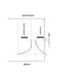
図2は、改質層の幅と改質位置変動とレーザパワー密度との関係を示すグラフである。 FIG. 2 is a graph showing the relationship between the width of the modified layer, variation in modified position, and laser power density.
このグラフでは、被加工物内部に形成される改質層の幅および改質位置変動と集光位置に照射されるレーザパワー密度、即ち単位時間および/又は単位速度辺りのレーザパワーの関係を示している。 This graph shows the relationship between the width of the modified layer formed inside the workpiece, the variation in the modified position, and the laser power density irradiated to the focused position, that is, the laser power per unit time and/or unit speed. ing.
このグラフから、改質層はレーザパワー密度の閾値A1で発生し、改質層の幅はレーザパワー密度が上昇するに伴い閾値A2まで増加していくことが分かる。レーザパワー密度が閾値A2まで増加すると、ウエハにクラックが発生したり割れが発生したりすることがある。 From this graph, it can be seen that the modified layer occurs at the threshold value A1 of the laser power density, and the width of the modified layer increases up to the threshold value A2 as the laser power density increases. When the laser power density increases to threshold A2, the wafer may crack or split.
また、このグラフから、改質層位置変動はレーザパワー密度が小さいときは大きく、レーザパワー密度の上昇に伴い減少していき、閾値A2で最小となることが分かる。 Also, from this graph, it can be seen that the modified layer position variation is large when the laser power density is low, decreases as the laser power density increases, and is minimized at the threshold value A2.
これらのことから、改質層の幅と改質層位置変動はトレードオフの関係であり、特に被加工物がGaNのように結晶の劈開方向が改質層形成方向と異なるものである場合、クラックや割れの発生はより容易となる。よって、両者を満足する条件を見出すことは極めて困難であった。 From these facts, the width of the modified layer and the variation of the modified layer position are in a trade-off relationship. Cracks and fractures are more likely to occur. Therefore, it has been extremely difficult to find a condition that satisfies both.
一方、ウエハの屈折率によるレーザ光の集光位置の補正は、レーザ光の中心部と周辺部との被加工物に対する入射角度の違いに伴う集光位置の補正に留まっていた。よって、被加工物の改質層の幅の抑制に対しては効果的であるものの、改質層位置変動に対する効果および結晶起因のクラックや割れの発生に対する効果はまだ十分ではなかった。 On the other hand, the correction of the focal position of the laser beam based on the refractive index of the wafer is limited to the correction of the focal position due to the difference in the incident angle of the laser beam with respect to the workpiece between the central portion and the peripheral portion. Therefore, although it is effective for suppressing the width of the modified layer of the workpiece, the effect on the modified layer position variation and the effect on the generation of cracks and fissures caused by the crystal are still insufficient.
(従来のレーザ加工装置の構成)
次に従来のレーザ加工装置について説明する。図3は、従来のレーザ加工装置の構成の一例を示す図である。(Configuration of conventional laser processing apparatus)
Next, a conventional laser processing apparatus will be described. FIG. 3 is a diagram showing an example of the configuration of a conventional laser processing apparatus.
この図において、301は被加工物であるインゴット、303は改質層を示している。改質層303は、インゴット301にレーザ光を集光照射した際にインゴット301の内部に形成される層であって、例えば、材料がGaNの場合、レーザ光の照射によって2GaN→2Ga+N2に分解される層のことである。 In this figure, 301 denotes an ingot as a workpiece, and 303 denotes a modified layer. The modified
従来のレーザ加工装置900は、レーザ光を照射(発振)するレーザ発振器901、レーザ光の分岐・形状・波形を制御する位相変調部903、レーザ光を反射するミラー904、レンズ位置調整部905、集光レンズ906、固定治具907、回転ステージ908、Zステージ909、XYステージ910、コントロールユニット911とから構成されている。 A conventional
従来のレーザ加工装置900では、レーザ光の偏波面および偏光方向を調整することができなかったため、レーザ加工においてはインゴット301の結晶方位に対するレーザ光の偏波面を考慮せずに、レーザ加工を実施した。 Since the conventional
(本発明のレーザ加工装置の構成)
以下、本発明のレーザ加工装置について説明する。図4は、本発明の実施形態に係るレーザ加工装置の構成の一例を示す図である。(Configuration of laser processing apparatus of the present invention)
A laser processing apparatus according to the present invention will be described below. FIG. 4 is a diagram showing an example of the configuration of the laser processing apparatus according to the embodiment of the present invention.
図4を参照し、本発明のレーザ加工装置100は、レーザ発振器101、偏波面調整部102、位相変調部103、ミラー104、レンズ位置調整部105、集光レンズ106、固定治具107、回転ステージ108、Zステージ109、XYステージ110、レーザ加工制御部111、そして、ディテクタ部121と結晶方位測定制御部122とデータ格納部123とからなる結晶方位測定部120とから構成されている。 Referring to FIG. 4, the
レーザ発振器101は、レーザ光を発振(出射)する装置である。各被加工物に対する透過率を考慮したレーザ波長を選択するにより、効率の良いレーザ加工が可能である。発振されるレーザ光は、インゴット301であるGaNに対して80%以上透過する波長を有し、その波長が532nmであり、最大繰返し周波数が1MHzのパルス発振をすることができ、最大出力100W、パルス幅25ps以下である。 The
偏波面調整部102は、レーザ光を通過あるいは反射することにより、発振されたレーザ光の偏波面の角度を調整するためのものであり、ある一定の角度で偏波面を保持したり偏波面の角度を経時的に変更したりすることができる。偏波面調整部102により、偏波面の角度を調整することができるため、偏波面の偏光方向を変更することができる。偏波面調整部102として、例えば電気光学変調器(EO変調器)が挙げられるが、これに限定されるものではない。 The polarization
位相変調部103は、偏波面調整部102を通過、あるいは反射したレーザ光を複数のビームに分岐したりビームの形状や波形を変更したりするためのものである。位相変調部103として、例えば回折格子が挙げられるが、これに限定されるものではない。 The
ミラー104は、位相変調部103を通過したレーザ光を反射させるものであって、レーザの波長に対して90%以上の反射率を持つものである。 The
レンズ位置調整部105は、集光レンズ106を高速で変動させるための装置であって、周波数が高いため、高速切り替えが可能な電気光学変調器や音響光学素子を用いた装置であることが好ましい。例えば、音響光学素子を用いた装置を用いて加工に合わせて変位を変動するといった方法がある。 The lens
集光レンズ106は、ミラー104で反射されたレーザ光を集光し、インゴットの内部に照射するためのものである。集光レンズ106は、レーザ光が透過する材質であり、加工深度に応じて最適な収差量にレーザ光を補正することが可能である。なお、本実施形態では、波長532nmを透過する顕微鏡用の収差補正環付で、NA=0.85、f=2mm、100倍対物レンズを用いることにしている。 The
固定治具107は、インゴット301を固定するための治具である。固定治具107としては、例えば、インゴット301の側面を挟んで固定する機能を有するもの、接着させて固定する機能を有するもの、真空吸着する機能を有するもの等が考えられる。 A fixing
回転ステージ108は、固定治具107の下に配置され、回転速度が0.1rpm以上5000rpm以下の範囲において可変である。 The
Zステージ109は、回転ステージ108の下に配置され、インゴット301の全面を加工するために用いる駆動手段の一つである。Zステージ109は、精度が1μm、ストロークがZ方向に10mmである。 The
XYステージ110は、Zステージ109の下に配置され、インゴット301の全面を加工するために用いる駆動手段の一つである。XYステージ110は、精度が1μm、ストロークがXY方向共に200mmであり、走査速度が0.1mm/sec以上3m/sec以下の範囲において可変可能である。 The
レーザ加工制御部111は、レーザ加工装置100を制御するためのものである。レーザ加工制御部111は、レーザ発振器101のレーザ光の発振のON/OFF制御、偏波面調整部102の偏波面の角度調整、レンズ位置調整部105による集光レンズ106の変動制御を行う。 The laser
また、レーザ加工制御部111は、偏波面調整部102の偏波面の角度とレンズ位置調整部105による集光レンズ106の変動に同期して、回転ステージ108、Zステージ109、XYステージ110の各ステージを制御する。なお、レーザ加工制御部111は、後述する結晶方位測定部120のデータ格納部123に格納された結晶方位測定データをもとに、偏波面調整部102とXYステージ110とを同期させてレーザ加工を実施する。 In addition, the laser
結晶方位測定部120は、インゴット301の結晶方位を測定するためのものであって、ディテクタ部121、結晶方位測定制御部122、データ格納部123とから構成される。結晶方位測定部120として、例えば、X線回折を用いる方式によって結晶方位を測定するXRD(X線回析装置)が挙げられるが、これ限定されるものではない。 The crystal
ディテクタ部121は、インゴット301表面の位置座標、即ちX、Y座標に対する結晶方位のデータを測定するためのものである。 The
データ格納部123は、ディテクタ部121により測定されたインゴット301表面の位置座標、即ちX、Y座標に対する結晶方位のデータを格納するためのものである。 The
結晶方位測定制御部122は、結晶方位測定部120を制御するためのものであって、ディテクタ部121による結晶方位測定制御、測定された結晶方位データをデータ格納部123に格納する処理、データ格納部123に格納された結晶方位データをレーザ加工制御部111に送信する処理を行う。 The crystal orientation
なお、本実施形態においては、レーザ加工装置100の構成として結晶方位測定部120を含むものを前提としているが、これに限られない。例えば、レーザ加工装置100の構成に結晶方位測定部120を含めないようにしてもよい。このような構成にした場合は、予め結晶方位測定部120を備える結晶方位測定装置(図示なし)により測定され格納された結晶方位データをレーザ加工制御部111に手動もしくは自動登録し、この登録した結晶方位データを用いることによって、上述のように偏波面調整部102とXYステージ110とを同期させたレーザ加工を実施することができる。 In addition, in the present embodiment, it is assumed that the configuration of the
以上、本発明のレーザ加工装置100の構成について説明した。本発明のレーザ加工装置100と上述した従来のレーザ加工装置900において最も特徴的な違いは、偏波面調整部102の有無である。即ち、従来のレーザ加工装置900では、レーザ光の偏波面および偏光方向を調整することができなかった。 The configuration of the
(レーザ光の走査方法)
図5は、本発明の実施形態に係るレーザ加工装置のレーザ光の走査方法を示す図である。(laser beam scanning method)
FIG. 5 is a diagram showing a laser beam scanning method of the laser processing apparatus according to the embodiment of the present invention.
図5は、XYステージ110を用いてレーザ光を直線的に走査するときの走査方法を示している。この図において幅Dは、XYステージ110の移動によりレーザ光が直線的に走査する場合の各ライン間のピッチを示している。また開始点Sは、レーザ光の照射開始位置を示し、終点Eは、レーザ光の照射終了位置を示している。 FIG. 5 shows a scanning method when the
照射されたレーザ光は、まず、XYステージ110の直線的な移動によって直線(Y方向)上を順方向に走査する。続いて前回の走査に対してX方向に幅Dだけ移動した後、前回の走査方向に対して逆方向にXYステージ110が直線的に移動することによって、レーザ光は直線(Y方向)上を前回とは逆方向に走査する。以降、この動作をレーザ光が終点Eに到達するまで繰り返すことにより、インゴット301の全面をレーザ加工する。 The irradiated laser light first scans in a straight line (Y direction) in the forward direction by linear movement of the
なお、レーザ加工の際、インゴット301の外縁部に形成される改質層303からガスを抜くために、インゴット301に対して連続した改質層を形成する必要がある。このような場合、レーザ光の走査速度やレーザパワー、周波数に応じて変化するパルス間の間隔や、幅Dの変化により改質層303の形成量を変化させる。 It should be noted that it is necessary to form a continuous modified layer on the
(結晶方位測定処理)
次に、本発明の実施形態に係る結晶方位測定処理について説明する。図6は、本発明の実施形態に係る結晶方位測定処理を示すフローチャートである。この結晶方位測定処理は、上述した結晶方位測定部120の結晶方位測定制御部122により実行される。(Crystal orientation measurement process)
Next, the crystal orientation measurement process according to the embodiment of the present invention will be explained. FIG. 6 is a flowchart showing crystal orientation measurement processing according to the embodiment of the present invention. This crystal orientation measurement process is executed by the crystal orientation
まず、ステップS1において結晶方位測定制御部122は、測定対象であるインゴット(被加工物)301がX,Y座標上に設置されたか否かを判断する。X,Y座標上にインゴット301が設置されていない場合、この処理を繰り返す。 First, in step S1, the crystal orientation
次に、ステップS2において結晶方位測定制御部122は、インゴット301のX,Y座標に対する結晶方位の測定を行う。 Next, in step S<b>2 , the crystal orientation
次に、ステップS3において結晶方位測定制御部122は、測定した結晶方位データをデータ格納部123に格納させる。 Next, in step S3, the crystal orientation
次に、ステップS4において結晶方位測定制御部122は、測定対象のインゴット301に対する測定対象範囲全域の測定が全て終了したか否かを判断する。測定対象範囲全域の測定が全て終了していないと判断した場合、ステップS2に進み、ステップS2およびステップS3の処理を繰り返す。測定対象範囲全域の測定が全て終了したと判断した場合、結晶方位測定処理を終了する。 Next, in step S4, the crystal orientation
(レーザ加工処理)
次に、本発明の実施形態に係るレーザ加工処理について説明する。図7は、本発明の実施形態に係るレーザ加工処理を示すフローチャートである。このレーザ加工処理は、上述したレーザ加工制御部111により実行される。(laser processing)
Next, laser processing according to an embodiment of the present invention will be described. FIG. 7 is a flow chart showing laser processing according to an embodiment of the present invention. This laser processing is executed by the laser
まずステップS11においてレーザ加工制御部111は、加工対象であるインゴット(被加工物)301がX,Y座標上に設置された(固定治具107により固定された)か否かを判断する。X,Y座標上にインゴットが設置されていない場合、この処理を繰り返す。 First, in step S11, the laser
次に、ステップS12においてレーザ加工制御部111は、加工対象であるインゴット301の結晶方位測定データを上述した結晶方位測定制御部122のデータ格納部123から取得する。この処理においてレーザ加工制御部111は、結晶方位測定制御部122に対して今回の加工対象であるインゴット301を特定可能なインゴット特定データを含む方位測定データ要求を送信する。この要求を受信した結晶方位測定制御部122は、データ格納部123に格納された各結晶方位測定データの中から、インゴット特定データにより特定された結晶方位測定データを抽出し、レーザ加工制御部111に送信する。 Next, in step S12, the laser
次に、ステップS13においてレーザ加工制御部111は、取得した結晶方位測定データから加工対象のインゴット301の表面におけるX,Y座標に対する結晶方位のA面に対する垂直方向データを算出する。 Next, in step S13, the laser
次に、ステップS14においてレーザ加工制御部111は、算出された垂直方向データにより、照射されるレーザの走査方向がインゴット301の表面における結晶方位のA面に対して垂直方向となるように、偏波面調整部102の偏波面の角度を制御することによりレーザ光の偏光方向を調整する。 Next, in step S14, the laser
次に、ステップS15においてレーザ加工制御部111は、レーザ発振器101からレーザ光を発振(出射)させる。これにより、インゴット301の結晶内部に集光されたレーザ光によるレーザ加工が実行される。 Next, in step S<b>15 , the laser
次に、ステップS16においてレーザ加工制御部111は、加工対象のインゴット301に対する加工対象範囲全域のレーザ加工が全て終了したか否かを判断する。加工対象範囲全域のレーザ加工が全て終了していないと判断した場合、ステップS12に進み、ステップS12からステップS15の処理を繰り返す。加工対象範囲全域のレーザ加工が全て終了したと判断した場合、レーザ加工処理を終了する。 Next, in step S16, the laser
なお、このレーザ加工処理では、上述したステップS12において結晶方位測定部120から結晶方位データを取得するようにしているが、これに限られない。予め結晶方位測定部120を備える結晶方位測定装置(図示なし)により測定され格納された結晶方位データをレーザ加工制御部111にオペレータ等により手動もしくは自動登録し、この登録した結晶方位データを用いること同様のレーザ加工処理を実施することもできる。 In this laser processing, the crystal orientation data is obtained from the crystal
このようなレーザ加工処理を行った場合のインゴット301の表面における結晶方位のA面に対するレーザ光の走査方向について説明する。図8は、本発明の実施形態に係る結晶方位のA面に対するレーザ光の走査方向のイメージを示す図である。 The scanning direction of the laser light with respect to the A-plane of the crystal orientation on the surface of the
この図に示すように、レーザ加工対象のインゴット301について測定されたX,Y座標に対する結晶方位データを基にレーザ加工制御部111により、インゴット301の表面におけるX,Y座標に対する結晶方位のA面に対する垂直方向データ算出される。そして、算出された垂直方向データとレーザ光の走査方向が合う、つまり、レーザ光の偏光方向が結晶方位のA面に対して垂直方向に沿うように偏波面調整部102により偏波面を経時的に調整しながらインゴット301の結晶内部にレーザ光を集光させレーザ加工を行う。 As shown in this figure, based on the crystal orientation data for the X and Y coordinates measured for the
ここでは、インゴット301の表面に、レーザ波長1100nm以下、パルス幅1fnsec以上1nsec以下、周波数2MHz以下、集光レンズのNA0.4以上0.95以下、パルス間ピッチおよびライン間ピッチは集光スポット径以下でレーザ光を照射した。 Here, on the surface of the
なお、インゴット301の厚みや直径は特に限定されるものではないが、厚み50mm以上10mm以下、直径100mm以下であればよい。またインゴット301は、内部に改質層303を形成できる材料であればGaNに限定されない。 Although the thickness and diameter of the
また、レーザ発振器101から発振されるレーザ光は、波長が100nm以上10000nm以下の範囲であれば制限されるものではない。しかしながら、集光させたときのスポット径が小さいと熱影響を低減させることができるため、レーザ光の波長が短い方が望ましい。また、レーザ光のパルス幅は50ps以下の範囲で、多光子吸収による内部加工が可能であればよい。 Moreover, the laser light emitted from the
また、繰り返し周波数は、生産性を考えた場合は繰り返し周波数が高い方が良いが、1Hz以上5MHz以下の範囲でバランスの良いものを適用することが好ましい。 As for the repetition frequency, it is preferable to use a high repetition frequency in consideration of productivity, but it is preferable to apply a well-balanced repetition frequency in the range of 1 Hz to 5 MHz.
また、集光レンズ106は、レーザ光の波長に対して、開口数(NA)が、0.1以上0.95以下であることが好ましい。 Further, the
収差補正機能は、レンズの球面収差による集光点のレーザ光の入射方向への伸びを抑制することが出来る機能である。集光点でのレーザ光のエネルギー密度を高くできるので、収差補正機能がある方が望ましい。なお、収差補正方法については、本実施形態の集光レンズのように収差補正環付を用いる方法や、位相変調素子を用いた方法でも良く、特に限定されるものではない。 The aberration correction function is a function capable of suppressing elongation of the focal point in the incident direction of the laser beam due to the spherical aberration of the lens. Since the energy density of the laser beam at the focal point can be increased, it is desirable to have an aberration correction function. The method of correcting aberration is not particularly limited and may be a method using an aberration correction ring as in the condenser lens of this embodiment, or a method using a phase modulating element.
レーザ加工方法は、インゴット301の結晶内部にレーザ光を照射させながらX軸方向および/又はY軸方向にXYステージ110を移動させ、インゴット301の表面における結晶302のA面方向に対してレーザ光の走査方向が垂直方向に沿うように偏波面調整部102によりレーザ光の偏光方向を調整し、インゴット301全面にレーザ加工を施していく。 The laser processing method moves the
図11は、レーザ加工後の改質層の形成状態を示す図である。図11(a)はインゴット301の表面からレーザ光が照射されることでインゴット301の結晶内部に形成された改質層303を示している。また図11(b)は、図11(a)におけるインゴット301の結晶内部に形成された改質層303の断面を示している。 FIG. 11 is a diagram showing a formation state of a modified layer after laser processing. FIG. 11A shows a modified
レーザ加工によって、インゴット301内部には改質層の幅がD2であり改質層位置変動幅がD3の改質層303が形成される。なお、この改質層303を分離面としてインゴット301をスライスすることによってウエハ(例えば、GaNウエハ)が作製される。 A modified
このようなレーザ加工方法によって、図11に示すようなインゴット301にはクラックや割れが発生することなく改質層303が形成される。なお、この場合の改質層の幅D2は8~15μmであり、改質層位置変動幅D3は3~5μmとなる。 By such a laser processing method, the modified
なお、上述した従来のレーザ加工装置901を用いて、インゴット301の結晶方位とレーザ光との偏波面を考慮せずにレーザ加工を実施した結果、この場合の改質層の幅D2は12~25μmであり、改質層位置変動幅D3は5~10μmであった。 As a result of performing laser processing using the above-described conventional
(その他の実施形態)
上述した実施形態におけるXYステージ110によるX軸方向および/又はY軸方向の移動に加え、回転ステージ108による回転軸方向の移動を加味してレーザ加工を行うようにすることが考えられる。(Other embodiments)
In addition to the movement in the X-axis direction and/or the Y-axis direction by the
(レーザ光の他の走査方法)
図9は本発明の他の実施形態に係るレーザ加工装置のレーザ光の走査方法を示す図である。この図に示すように、本実施形態では、XYステージ110と回転ステージ108を用いて円周上に並べられた複数のインゴット301a、301b、301c…の各々に対してレーザ光を直線的に走査する。このような場合、回転ステージ108により回転軸方向に回転させながらXYステージ110によりX軸方向および/又はY軸方向に直線的に移動させることにより固定治具107の中心方向に向けてレーザ光を走査させる。(Other Scanning Methods of Laser Light)
FIG. 9 is a diagram showing a laser beam scanning method of a laser processing apparatus according to another embodiment of the present invention. As shown in this figure, in this embodiment, a plurality of
インゴット301に対してX軸方向および/又はY軸方向と回転軸方向とが走査速度、すなわち線速度が一定になるようにレーザ光を走査させてインゴット301の結晶内にレーザ光を照射させながらレーザ加工を行う場合、インゴット301の表面における結晶302のA面方向に対してレーザの走査方向が垂直となるように、偏波面調整部102によりレーザ光の偏光方向を経時的に調整しながら、インゴット301にレーザ加工を施していく。
よって、XYステージ110よるX軸方向および/又はY軸方向の移動と回転ステージ108の回転軸方向の移動に対して偏波面調整部102によりレーザ光の偏波面を連続的に調整させながらレーザ加工を行っていく。While scanning the
Therefore, laser processing is performed while the polarization
このときレーザ加工制御部111は、レーザ光の集光点での走査速度、即ち線速度が一定となるようにXYステージ110と回転ステージ108を協調制御することにより、レーザ光のパルスが等間隔に照射していく。なお、その他の点においては図5を用いて上述した内容と同様である。 At this time, the laser
図10は、本発明の他の実施形態に係るインゴット301の表面における結晶方位のA面に対するレーザ照射の走査方向のイメージを示す図である。 FIG. 10 is a diagram showing an image of the scanning direction of laser irradiation with respect to the A-plane of the crystal orientation on the surface of the
他の実施形態においても、上述した実施形態と同様に、レーザ加工対象のインゴット301について測定されたX,Y座標に対する結晶方位データを基に、レーザ加工制御部111により、インゴット301のX,Y座標に対する結晶方位のA面に対する垂直方向データ算出される。そして、算出された垂直方向データとレーザ光の走査方向が合う、つまり、レーザ光の偏光方向がインゴット301の表面における結晶方位のA面に対して垂直方向となるように偏波面調整部102により偏波面を経時的に調整しながらインゴット301の結晶内部にレーザ光を集光させレーザ加工を行う。 In other embodiments, as in the above-described embodiment, the laser
ここでは上述した実施形態と同様、インゴット301の表面にレーザ波長1100nm以下、パルス幅1fsec以上1nsec以下、周波数2MHz以下、集光レンズのNA0.4以上0.95以下、パルス間ピッチ及びライン間ピッチは集光スポット径以下で表面にレーザを照射した。 Here, as in the above-described embodiment, a laser wavelength of 1100 nm or less, a pulse width of 1 fsec or more and 1 nsec or less, a frequency of 2 MHz or less, a condenser lens NA of 0.4 or more and 0.95 or less, an inter-pulse pitch and an inter-line pitch are applied to the surface of the
このようなレーザ加工方法によって、図11に示すようなインゴット301にはクラックや割れが発生することなく改質層303が形成される。なお、この場合の改質層の幅D2は8~12μmであり、改質層位置変動幅D3は3~5μmとなる。 By such a laser processing method, the modified
以上、本発明の実施形態では、レーザ加工はインゴット301における測定範囲全域について実行するようにした。測定対象のインゴット301が単結晶である場合は、インゴット301の測定範囲全域において、結晶302のA面方向は略一律であると考えられる。一方、インゴット301が多結晶である場合は、インゴット301の測定範囲内全域において、結晶302のA面方向は結晶ごとに異なると考えられる。 As described above, in the embodiment of the present invention, the laser processing is performed over the entire measurement range of the
そのため、本発明の実施形態では、レーザ光が照射されるインゴット301の表面の結晶302のA面方向に対してレーザ光の走査方向、すなわち、レーザ光の偏光方向が垂直となるように、レーザ光の偏光方向を経時的に調整しながら、インゴット301全面にレーザ加工を施すようにした。 Therefore, in the embodiment of the present invention, the scanning direction of the laser light, that is, the polarization direction of the laser light is perpendicular to the A-plane direction of the
以上、本発明の実施形態によれば、レーザ光を用いて硬脆性材料の内部に従来に比べて幅が低減した改質層を形成できるとともに、改質層位置変動幅の抑えることができる。よって、表面の粗研磨の時間効率を向上できるため、ウエハの作製効率を高めることができる。 As described above, according to the embodiments of the present invention, it is possible to form a modified layer with a reduced width in the interior of a hard-brittle material using a laser beam, and to suppress the positional fluctuation width of the modified layer. Therefore, since the time efficiency of rough polishing of the surface can be improved, the wafer production efficiency can be improved.
100 レーザ加工装置
101 レーザ発振器
102 偏波面調整部
103 位相変調部
104 ミラー
105 レンズ位置調整部
106 集光レンズ
107 固定治具
108 回転ステージ
109 Zステージ
110 XYステージ
111 レーザ加工制御部
120 結晶方位測定部
121 ディテクタ部
122 結晶方位測定制御部
123 データ格納部
301、301a~301c 被加工物(インゴット)
302 結晶
303 改質層
304 GaNウエハ
305a、305b 変質層
306 粗研磨ホイール
307 スラリー
308 CMP定盤
309 洗浄液
310 ワイヤ
900 従来のレーザ加工装置
901 レーザ発振器
903 位相変調部
904 ミラー
905 レンズ位置調整部
906 集光レンズ
907 固定治具
908 回転ステージ
909 Zステージ
910 XYステージ
911 コントロールユニット100
302
Claims (7)
Translated fromJapanese前記レーザ光の走査面において前記被加工物の結晶方位のA面を示す線に対する垂直方向を特定する垂直方向特定手段と、
前記レーザ光の偏波面を調整する偏波面調整手段と、を少なくとも含み、
前記偏波面調整手段は、
前記レーザ光の走査中において、特定された前記垂直方向に前記偏波面の偏光方向が沿うように、前記レーザ光の偏波面を調整する、
レーザ加工装置。A laser processing device for processing a workpiece byscanning a focused laser beam,
vertical direction specifying means for specifying a direction perpendicularto a line indicating the A-plane of the crystal orientation of the workpiecein the scanning plane of the laser beam ;
and at leasta polarization plane adjustment means for adjusting the polarization plane of the laser light ,
The polarization plane adjustment means is
adjusting the plane ofpolarization of the laser light so that thedirection of polarization of the plane of polarization is aligned withthe specified vertical directionduring scanning of the laser light;
Laser processing equipment.
前記垂直方向特定手段は、前記結晶方位測定手段によって測定された前記被加工物の結晶方位に基づき、前記垂直方向を特定する、
請求項1に記載のレーザ加工装置。Furthermore, including crystal orientation measuring means for measuring the crystal orientation of the workpiece,
the vertical direction identifying means identifiesthe vertical direction based on the crystal orientation of the workpiece measured by the crystal orientation measuring means;
The laser processing apparatus according to claim 1.
前記レーザ光を照射する前記被加工物の表面における結晶方位を測定する、
請求項2に記載のレーザ加工装置。The crystal orientation measuring means is
measuring the crystal orientation on the surface of the workpiece irradiated with the laser light;
The laser processing apparatus according to claim 2.
前記レーザ光を集光するレンズの開口数が0.4以上0.95以下である、
請求項1~3のいずれかに記載のレーザ加工装置。The laser light has a wavelength of 1100 nm or less, a pulse width of 1 fsec or more and 1 nsec or less, and a frequency of 2 MHz or less,
The lens for condensing the laser light has a numerical aperture of 0.4 or more and 0.95 or less.
A laser processing apparatus according to any one of claims 1 to 3.
請求項1~4のいずれかに記載のレーザ加工装置。Processing gallium nitride as the workpiece,
A laser processing apparatus according to any one of claims 1 to 4.
前記レーザ光の走査面において前記被加工物の結晶方位のA面を示す線に対する垂直方向を特定する垂直方向特定工程と、
前記レーザ光の偏波面を調整する偏波面調整工程と、を少なくとも含み、
前記偏波面調整工程では、
前記レーザ光の走査中において、特定された前記垂直方向に前記偏波面の偏光方向が沿うように前記偏波面を調整する、
レーザ加工方法。A laser processing method for processing a workpiece byscanning a focused laser beam,
a vertical direction specifying step of specifying a direction perpendicularto a line indicating the A-plane of the crystal orientation of the workpiecein the scanning plane of the laser beam ;
At leasta polarization plane adjustment step of adjusting the polarization plane of the laser light ,
In the polarization plane adjustment step,
adjusting the plane ofpolarization so thatthe direction of polarization of the plane of polarization is aligned withthe specified vertical directionduring scanning of the laser light ;
Laser processing method.
前記垂直方向特定工程において、前記結晶方位測定工程によって測定された前記被加工物の結晶方位に基づき、前記垂直方向を特定する、
請求項6に記載のレーザ加工方法。further comprising a crystal orientation measurement step of measuring the crystal orientation of the workpiece;
In the vertical direction identifying step,the vertical direction is identified based on the crystal orientation of the workpiece measured by the crystal orientation measuring step.
The laser processing method according to claim 6.
Priority Applications (2)
| Application Number | Priority Date | Filing Date | Title |
|---|---|---|---|
| JP2019030351AJP7217426B2 (en) | 2019-02-22 | 2019-02-22 | LASER PROCESSING APPARATUS AND LASER PROCESSING METHOD |
| US16/776,929US20200269357A1 (en) | 2019-02-22 | 2020-01-30 | Laser processing device and laser processing method |
Applications Claiming Priority (1)
| Application Number | Priority Date | Filing Date | Title |
|---|---|---|---|
| JP2019030351AJP7217426B2 (en) | 2019-02-22 | 2019-02-22 | LASER PROCESSING APPARATUS AND LASER PROCESSING METHOD |
Publications (2)
| Publication Number | Publication Date |
|---|---|
| JP2020131259A JP2020131259A (en) | 2020-08-31 |
| JP7217426B2true JP7217426B2 (en) | 2023-02-03 |
Family
ID=72141200
Family Applications (1)
| Application Number | Title | Priority Date | Filing Date |
|---|---|---|---|
| JP2019030351AActiveJP7217426B2 (en) | 2019-02-22 | 2019-02-22 | LASER PROCESSING APPARATUS AND LASER PROCESSING METHOD |
Country Status (2)
| Country | Link |
|---|---|
| US (1) | US20200269357A1 (en) |
| JP (1) | JP7217426B2 (en) |
Families Citing this family (6)
| Publication number | Priority date | Publication date | Assignee | Title |
|---|---|---|---|---|
| DE102019201438B4 (en)* | 2019-02-05 | 2024-05-02 | Disco Corporation | Method for producing a substrate and system for producing a substrate |
| JP7217426B2 (en)* | 2019-02-22 | 2023-02-03 | パナソニックIpマネジメント株式会社 | LASER PROCESSING APPARATUS AND LASER PROCESSING METHOD |
| JP7749354B2 (en)* | 2021-06-21 | 2025-10-06 | 株式会社ディスコ | Processing method |
| JP2023023236A (en)* | 2021-08-04 | 2023-02-16 | 株式会社ディスコ | Chip manufacturing method |
| EP4163046A1 (en)* | 2021-10-07 | 2023-04-12 | Denso Corporation | Method for manufacturing wafers |
| JP7646236B1 (en) | 2023-10-19 | 2025-03-17 | 西進商事株式会社 | Wafer manufacturing method, wafer separation method, plate-like body forming unit, substrate separation unit, substrate forming apparatus, and wafer separation unit |
Citations (3)
| Publication number | Priority date | Publication date | Assignee | Title |
|---|---|---|---|---|
| JP2016157872A (en) | 2015-02-25 | 2016-09-01 | キヤノン株式会社 | Generation method of semiconductor chip |
| JP2016197698A (en) | 2015-04-06 | 2016-11-24 | 株式会社ディスコ | Wafer generation method |
| US20180154572A1 (en) | 2015-03-12 | 2018-06-07 | Siltectra Gmbh | Apparatus and method for continuous treatment of a solid body by means of laser beam |
Family Cites Families (7)
| Publication number | Priority date | Publication date | Assignee | Title |
|---|---|---|---|---|
| JP3532100B2 (en)* | 1997-12-03 | 2004-05-31 | 日本碍子株式会社 | Laser cleaving method |
| US8950217B2 (en)* | 2010-05-14 | 2015-02-10 | Hamamatsu Photonics K.K. | Method of cutting object to be processed, method of cutting strengthened glass sheet and method of manufacturing strengthened glass member |
| JP5906198B2 (en)* | 2011-02-08 | 2016-04-20 | 株式会社フジクラ | Manufacturing method of substrate having micropores, and substrate |
| KR102563724B1 (en)* | 2017-11-29 | 2023-08-07 | 니치아 카가쿠 고교 가부시키가이샤 | Manufacturing method of semiconductor light emitting device |
| CN111868886B (en)* | 2018-04-09 | 2024-01-05 | 东京毅力科创株式会社 | Laser processing device, laser processing system, and laser processing method |
| US10576585B1 (en)* | 2018-12-29 | 2020-03-03 | Cree, Inc. | Laser-assisted method for parting crystalline material |
| JP7217426B2 (en)* | 2019-02-22 | 2023-02-03 | パナソニックIpマネジメント株式会社 | LASER PROCESSING APPARATUS AND LASER PROCESSING METHOD |
- 2019
- 2019-02-22JPJP2019030351Apatent/JP7217426B2/enactiveActive
- 2020
- 2020-01-30USUS16/776,929patent/US20200269357A1/ennot_activeAbandoned
Patent Citations (3)
| Publication number | Priority date | Publication date | Assignee | Title |
|---|---|---|---|---|
| JP2016157872A (en) | 2015-02-25 | 2016-09-01 | キヤノン株式会社 | Generation method of semiconductor chip |
| US20180154572A1 (en) | 2015-03-12 | 2018-06-07 | Siltectra Gmbh | Apparatus and method for continuous treatment of a solid body by means of laser beam |
| JP2016197698A (en) | 2015-04-06 | 2016-11-24 | 株式会社ディスコ | Wafer generation method |
Also Published As
| Publication number | Publication date |
|---|---|
| JP2020131259A (en) | 2020-08-31 |
| US20200269357A1 (en) | 2020-08-27 |
Similar Documents
| Publication | Publication Date | Title |
|---|---|---|
| JP7217426B2 (en) | LASER PROCESSING APPARATUS AND LASER PROCESSING METHOD | |
| JP7605915B2 (en) | Laser-assisted method for cutting crystalline materials | |
| JP7315677B2 (en) | Laser-assisted method for cutting crystalline materials | |
| JP6516184B2 (en) | Apparatus and method for slicing brittle substrate | |
| JP5917862B2 (en) | Processing object cutting method | |
| US6992026B2 (en) | Laser processing method and laser processing apparatus | |
| KR101037142B1 (en) | Program-controlled dicing of substrate using pulse laser | |
| JP5875122B2 (en) | Single crystal substrate manufacturing method and internal modified layer forming single crystal member | |
| KR101243543B1 (en) | Dicing methods | |
| CN110064840B (en) | Laser slicing device and laser slicing method | |
| JP6004339B2 (en) | Internal stress layer forming single crystal member and single crystal substrate manufacturing method | |
| US20050224475A1 (en) | Laser beam processing machine | |
| JP7283886B2 (en) | Slicing method and slicing apparatus | |
| JP7123759B2 (en) | Laser slicing device and laser slicing method | |
| JP6818273B2 (en) | Substrate processing method | |
| JP7210292B2 (en) | Wafer generation method | |
| JP2016164924A (en) | Single crystal substrate processing method | |
| JP7316639B2 (en) | Substrate separation method | |
| JP7542917B2 (en) | Wafer Production Method | |
| JP6202695B2 (en) | Single crystal substrate manufacturing method | |
| KR102021154B1 (en) | Machining method and machining apparatus | |
| JP2016030288A (en) | Laser processing method and manufacturing method of sheet glass blank | |
| JP2020141009A (en) | Substrate material and laser processing method | |
| JP6851040B2 (en) | Substrate processing method and substrate processing equipment | |
| EP4632795A1 (en) | Chamfering method and chamfering device |
Legal Events
| Date | Code | Title | Description |
|---|---|---|---|
| RD02 | Notification of acceptance of power of attorney | Free format text:JAPANESE INTERMEDIATE CODE: A7422 Effective date:20190625 | |
| RD04 | Notification of resignation of power of attorney | Free format text:JAPANESE INTERMEDIATE CODE: A7424 Effective date:20191021 | |
| A621 | Written request for application examination | Free format text:JAPANESE INTERMEDIATE CODE: A621 Effective date:20211209 | |
| A977 | Report on retrieval | Free format text:JAPANESE INTERMEDIATE CODE: A971007 Effective date:20221027 | |
| A131 | Notification of reasons for refusal | Free format text:JAPANESE INTERMEDIATE CODE: A131 Effective date:20221101 | |
| A521 | Request for written amendment filed | Free format text:JAPANESE INTERMEDIATE CODE: A523 Effective date:20221215 | |
| TRDD | Decision of grant or rejection written | ||
| A01 | Written decision to grant a patent or to grant a registration (utility model) | Free format text:JAPANESE INTERMEDIATE CODE: A01 Effective date:20230110 | |
| A61 | First payment of annual fees (during grant procedure) | Free format text:JAPANESE INTERMEDIATE CODE: A61 Effective date:20230112 | |
| R151 | Written notification of patent or utility model registration | Ref document number:7217426 Country of ref document:JP Free format text:JAPANESE INTERMEDIATE CODE: R151 |