JP7213809B2 - Video-based positioning and mapping method and system - Google Patents
Video-based positioning and mapping method and systemDownload PDFInfo
- Publication number
- JP7213809B2 JP7213809B2JP2019529215AJP2019529215AJP7213809B2JP 7213809 B2JP7213809 B2JP 7213809B2JP 2019529215 AJP2019529215 AJP 2019529215AJP 2019529215 AJP2019529215 AJP 2019529215AJP 7213809 B2JP7213809 B2JP 7213809B2
- Authority
- JP
- Japan
- Prior art keywords
- image
- images
- map
- road
- vehicle
- Prior art date
- Legal status (The legal status is an assumption and is not a legal conclusion. Google has not performed a legal analysis and makes no representation as to the accuracy of the status listed.)
- Active
Links
Images


Classifications
- G—PHYSICS
- G06—COMPUTING OR CALCULATING; COUNTING
- G06V—IMAGE OR VIDEO RECOGNITION OR UNDERSTANDING
- G06V20/00—Scenes; Scene-specific elements
- G06V20/50—Context or environment of the image
- G06V20/56—Context or environment of the image exterior to a vehicle by using sensors mounted on the vehicle
- G06V20/588—Recognition of the road, e.g. of lane markings; Recognition of the vehicle driving pattern in relation to the road
- G—PHYSICS
- G01—MEASURING; TESTING
- G01C—MEASURING DISTANCES, LEVELS OR BEARINGS; SURVEYING; NAVIGATION; GYROSCOPIC INSTRUMENTS; PHOTOGRAMMETRY OR VIDEOGRAMMETRY
- G01C21/00—Navigation; Navigational instruments not provided for in groups G01C1/00 - G01C19/00
- G01C21/26—Navigation; Navigational instruments not provided for in groups G01C1/00 - G01C19/00 specially adapted for navigation in a road network
- G01C21/28—Navigation; Navigational instruments not provided for in groups G01C1/00 - G01C19/00 specially adapted for navigation in a road network with correlation of data from several navigational instruments
- G01C21/30—Map- or contour-matching
- G01C21/32—Structuring or formatting of map data
- G—PHYSICS
- G01—MEASURING; TESTING
- G01C—MEASURING DISTANCES, LEVELS OR BEARINGS; SURVEYING; NAVIGATION; GYROSCOPIC INSTRUMENTS; PHOTOGRAMMETRY OR VIDEOGRAMMETRY
- G01C21/00—Navigation; Navigational instruments not provided for in groups G01C1/00 - G01C19/00
- G01C21/38—Electronic maps specially adapted for navigation; Updating thereof
- G01C21/3804—Creation or updating of map data
- G01C21/3807—Creation or updating of map data characterised by the type of data
- G01C21/3811—Point data, e.g. Point of Interest [POI]
- G—PHYSICS
- G01—MEASURING; TESTING
- G01C—MEASURING DISTANCES, LEVELS OR BEARINGS; SURVEYING; NAVIGATION; GYROSCOPIC INSTRUMENTS; PHOTOGRAMMETRY OR VIDEOGRAMMETRY
- G01C21/00—Navigation; Navigational instruments not provided for in groups G01C1/00 - G01C19/00
- G01C21/38—Electronic maps specially adapted for navigation; Updating thereof
- G01C21/3804—Creation or updating of map data
- G01C21/3833—Creation or updating of map data characterised by the source of data
- G01C21/3848—Data obtained from both position sensors and additional sensors
- G—PHYSICS
- G01—MEASURING; TESTING
- G01C—MEASURING DISTANCES, LEVELS OR BEARINGS; SURVEYING; NAVIGATION; GYROSCOPIC INSTRUMENTS; PHOTOGRAMMETRY OR VIDEOGRAMMETRY
- G01C21/00—Navigation; Navigational instruments not provided for in groups G01C1/00 - G01C19/00
- G01C21/38—Electronic maps specially adapted for navigation; Updating thereof
- G01C21/3804—Creation or updating of map data
- G01C21/3859—Differential updating map data
- G—PHYSICS
- G06—COMPUTING OR CALCULATING; COUNTING
- G06F—ELECTRIC DIGITAL DATA PROCESSING
- G06F16/00—Information retrieval; Database structures therefor; File system structures therefor
- G06F16/20—Information retrieval; Database structures therefor; File system structures therefor of structured data, e.g. relational data
- G06F16/29—Geographical information databases
- G—PHYSICS
- G06—COMPUTING OR CALCULATING; COUNTING
- G06F—ELECTRIC DIGITAL DATA PROCESSING
- G06F16/00—Information retrieval; Database structures therefor; File system structures therefor
- G06F16/50—Information retrieval; Database structures therefor; File system structures therefor of still image data
- G06F16/58—Retrieval characterised by using metadata, e.g. metadata not derived from the content or metadata generated manually
- G06F16/583—Retrieval characterised by using metadata, e.g. metadata not derived from the content or metadata generated manually using metadata automatically derived from the content
- G—PHYSICS
- G06—COMPUTING OR CALCULATING; COUNTING
- G06F—ELECTRIC DIGITAL DATA PROCESSING
- G06F16/00—Information retrieval; Database structures therefor; File system structures therefor
- G06F16/50—Information retrieval; Database structures therefor; File system structures therefor of still image data
- G06F16/58—Retrieval characterised by using metadata, e.g. metadata not derived from the content or metadata generated manually
- G06F16/587—Retrieval characterised by using metadata, e.g. metadata not derived from the content or metadata generated manually using geographical or spatial information, e.g. location
- G—PHYSICS
- G06—COMPUTING OR CALCULATING; COUNTING
- G06T—IMAGE DATA PROCESSING OR GENERATION, IN GENERAL
- G06T7/00—Image analysis
- G06T7/10—Segmentation; Edge detection
- G06T7/11—Region-based segmentation
- G—PHYSICS
- G06—COMPUTING OR CALCULATING; COUNTING
- G06T—IMAGE DATA PROCESSING OR GENERATION, IN GENERAL
- G06T7/00—Image analysis
- G06T7/70—Determining position or orientation of objects or cameras
- G06T7/73—Determining position or orientation of objects or cameras using feature-based methods
- G06T7/74—Determining position or orientation of objects or cameras using feature-based methods involving reference images or patches
- G—PHYSICS
- G06—COMPUTING OR CALCULATING; COUNTING
- G06T—IMAGE DATA PROCESSING OR GENERATION, IN GENERAL
- G06T7/00—Image analysis
- G06T7/70—Determining position or orientation of objects or cameras
- G06T7/73—Determining position or orientation of objects or cameras using feature-based methods
- G06T7/75—Determining position or orientation of objects or cameras using feature-based methods involving models
- G—PHYSICS
- G06—COMPUTING OR CALCULATING; COUNTING
- G06V—IMAGE OR VIDEO RECOGNITION OR UNDERSTANDING
- G06V10/00—Arrangements for image or video recognition or understanding
- G06V10/20—Image preprocessing
- G06V10/26—Segmentation of patterns in the image field; Cutting or merging of image elements to establish the pattern region, e.g. clustering-based techniques; Detection of occlusion
- G06V10/267—Segmentation of patterns in the image field; Cutting or merging of image elements to establish the pattern region, e.g. clustering-based techniques; Detection of occlusion by performing operations on regions, e.g. growing, shrinking or watersheds
- G—PHYSICS
- G06—COMPUTING OR CALCULATING; COUNTING
- G06V—IMAGE OR VIDEO RECOGNITION OR UNDERSTANDING
- G06V20/00—Scenes; Scene-specific elements
- G06V20/50—Context or environment of the image
- G06V20/56—Context or environment of the image exterior to a vehicle by using sensors mounted on the vehicle
- G06V20/58—Recognition of moving objects or obstacles, e.g. vehicles or pedestrians; Recognition of traffic objects, e.g. traffic signs, traffic lights or roads
- G06V20/582—Recognition of moving objects or obstacles, e.g. vehicles or pedestrians; Recognition of traffic objects, e.g. traffic signs, traffic lights or roads of traffic signs
- G—PHYSICS
- G06—COMPUTING OR CALCULATING; COUNTING
- G06T—IMAGE DATA PROCESSING OR GENERATION, IN GENERAL
- G06T2207/00—Indexing scheme for image analysis or image enhancement
- G06T2207/10—Image acquisition modality
- G06T2207/10016—Video; Image sequence
- G—PHYSICS
- G06—COMPUTING OR CALCULATING; COUNTING
- G06T—IMAGE DATA PROCESSING OR GENERATION, IN GENERAL
- G06T2207/00—Indexing scheme for image analysis or image enhancement
- G06T2207/30—Subject of image; Context of image processing
- G06T2207/30244—Camera pose
- G—PHYSICS
- G06—COMPUTING OR CALCULATING; COUNTING
- G06T—IMAGE DATA PROCESSING OR GENERATION, IN GENERAL
- G06T2207/00—Indexing scheme for image analysis or image enhancement
- G06T2207/30—Subject of image; Context of image processing
- G06T2207/30248—Vehicle exterior or interior
- G06T2207/30252—Vehicle exterior; Vicinity of vehicle
- G06T2207/30256—Lane; Road marking
Landscapes
- Engineering & Computer Science (AREA)
- Remote Sensing (AREA)
- Radar, Positioning & Navigation (AREA)
- Physics & Mathematics (AREA)
- General Physics & Mathematics (AREA)
- Theoretical Computer Science (AREA)
- Databases & Information Systems (AREA)
- Automation & Control Theory (AREA)
- General Engineering & Computer Science (AREA)
- Data Mining & Analysis (AREA)
- Library & Information Science (AREA)
- Computer Vision & Pattern Recognition (AREA)
- Multimedia (AREA)
- Traffic Control Systems (AREA)
- Navigation (AREA)
- Instructional Devices (AREA)
- Image Analysis (AREA)
- Image Processing (AREA)
- Apparatus For Radiation Diagnosis (AREA)
Description
Translated fromJapanese本開示は、観察者、例えば道路網に沿って走行する車両の地理的位置および向きを判定するための方法およびシステムに関する。さらに、電子地図を生成および/または更新するための(すなわち、マッピングのための)方法およびシステムが提供される。実施形態では、視覚的な全地球測位およびマッピングシステムを提供することができる。 The present disclosure relates to methods and systems for determining the geographic position and orientation of an observer, such as a vehicle traveling along a road network. Additionally, methods and systems for generating and/or updating electronic maps (ie, for mapping) are provided. Embodiments may provide a visual global positioning and mapping system.
ナビゲーションおよび移動計画は、高度に自動化された自律的な運転の重要な構成要素である。自律車両は安全な動作方針を判定するために、世界において自身を自動的に位置特定することができる必要がある。一方では、全地球測位システムによって解決されるルート計画のためのグローバルスケールでの位置特定を可能にするために地図が必要とされる。他方では、レーン維持および交通標識への順守のような機能のために、直接的な環境の正確な幾何学的表現が必要とされる。従来、これは、単に、事前の地図なしの周囲のアドホックセンシングによって、または、高度に精密な事前構築地図のサポートによって解決される。アドホックセンシングは自律動作に必要な最小限の能力であり、最近のセンサデータからのオンザフライ地図生成によって拡張されることが多い。これは、同じエリアが直後に再訪される場合に特に有用である。しかし、環境のアドホックセンシングはエラーを起こしやすく、周囲に関する高品質の情報(すなわち、マップ)をすでに有することが非常に望ましく、このことは、それに対してマッチングすることによって直接センシングを検証し、サポートすることを可能にする。 Navigation and trip planning are key components of highly automated and autonomous driving. Autonomous vehicles need to be able to automatically locate themselves in the world in order to determine a safe course of action. On the one hand, maps are needed to enable location on a global scale for route planning resolved by the Global Positioning System. On the other hand, functions such as lane keeping and traffic sign compliance require an accurate geometric representation of the immediate environment. Conventionally, this is solved simply by ad-hoc sensing of the surroundings without prior maps, or with the support of highly precise pre-built maps. Ad-hoc sensing is the minimal capability required for autonomous operation, often augmented by on-the-fly map generation from recent sensor data. This is especially useful when the same area is revisited shortly after. However, ad-hoc sensing of the environment is error-prone and it is highly desirable to already have high-quality information (i.e., a map) about the surroundings, which can validate and support direct sensing by matching against it. make it possible to
任意選択で、理想的には、高品質の事前構築地図がすでに利用可能であり、これにより、センシングエラーがオンザフライ地図に入り込むことが防止され、したがって、移動計画および車両の安全性が改善される。しかし、事前構築地図は、実際の自律運転中に世界がどのようなものであるかとは対照的に、かつて世界がどのようなものであったかを反映している。このことは、事前構築地図が、安全なナビゲーションおよび移動計画を確実にするために最新の状態に維持される必要があることを意味する。 Optionally, and ideally, high-quality pre-built maps are already available, which prevents sensing errors from creeping into on-the-fly maps, thus improving travel planning and vehicle safety . But pre-built maps reflect what the world once was, as opposed to what the world is like during actual autonomous driving. This means that pre-built maps need to be kept up to date to ensure safe navigation and travel planning.
現在の領域の地図とは別に、車両内の計画システムは、その地図内のどこに位置しているかを知る必要がある。アドホックセンシングから作成されるオンザフライ地図の場合、これは自明であるが、事前構築地図への直接の接続はない。有用であるためには、事前構築地図の構造および含まれる情報が、その中の車両の正確な位置特定を可能にする必要がある。オンザフライで作成された地図を事前構築地図と比較して位置合わせする何らかの方法によって、事前構築地図内の車両の位置および向きを判定する必要がある。これは、アドホックセンサデータとの比較に適したデータ表現のような、事前構築地図の設計に特定の要件を課す。 Apart from a map of the current area, the in-vehicle planning system needs to know where it is within that map. For on-the-fly maps created from ad-hoc sensing, this is trivial, but there is no direct connection to pre-built maps. To be useful, the structure and information contained in pre-built maps must allow for precise localization of vehicles therein. Some method of comparing and aligning the on-the-fly created map with the pre-built map needs to determine the position and orientation of the vehicle in the pre-built map. This imposes certain requirements on the design of pre-built maps, such as data representations suitable for comparison with ad-hoc sensor data.
自律運転のための地図は、用途の制限及び要件に適合する必要がある。自動車内の限られた資源は、計算時間、メモリ、および移動体帯域幅を経済的に使用するアルゴリズムおよびデータ構造を課す。これらの制約を尊重しながら、システムは、自律運転のための機能的要件を満たす必要がある。これらは、所与の地形の交通可能性、動的(例えば、他の自動車)および静的(例えば、道路建設、交通標識)オブジェクトの位置および動きなど、周囲に関するセマンティック情報を判定することを含む。 Maps for autonomous driving need to comply with usage restrictions and requirements. Limited resources within a vehicle impose algorithms and data structures that economically use computation time, memory, and mobile bandwidth. The system needs to meet the functional requirements for autonomous driving while respecting these constraints. These include determining semantic information about the surroundings, such as the trafficability of a given terrain, the position and movement of dynamic (e.g. other vehicles) and static (e.g. road construction, traffic signs) objects. .
大規模な展開のために、地図は過剰な道路形状およびアーチファクトを組み込むのに十分に柔軟である必要があり、最新性および性能を犠牲にすることなく、グローバルサイズにスケーリングすることができる必要がある。データ構造は、追加の幾何学的層およびセマンティック層のために十分に拡張可能である必要がある。 For large-scale deployment, maps need to be flexible enough to incorporate excess road geometry and artifacts, and need to be able to scale to global sizes without sacrificing recency and performance. be. The data structure should be sufficiently extensible for additional geometric and semantic layers.
自律運転は積極的な研究分野であり、毎年、自走車の充実に向けて大きな進展が見られる。しかし、完全な自律性のために必要とされる多くの課題は解決されておらず、研究コミュニティは安全な計画および運転のためのすべての前提条件をまだ決定していなかったが、明確な解決策が存在しない既知の問題さえ存在する。 Autonomous driving is an active research area, and each year we see significant progress towards the enrichment of self-driving vehicles. However, many of the challenges required for full autonomy remain unsolved, and although the research community had not yet determined all the prerequisites for safe planning and operation, no clear solutions were possible. There are even known problems for which no workaround exists.
自律運転プラットフォームには多くの提案および実施があるが、マッピングおよび位置特定の問題について受け入れられている標準的な解決策の状態は得られていない。また、アドホックデータをオンザフライ地図に集約するための標準的な解決策は存在せず、これは、即時の移動計画と、グローバルスケールで事前に構築された地図に対する追加の地図マッチング(すなわち、位置特定)とを同時に容易にする。 Although there are many proposals and implementations for autonomous driving platforms, the status of accepted standard solutions for mapping and localization problems has not been achieved. Also, no standard solution exists for aggregating ad-hoc data into an on-the-fly map, which requires immediate movement planning and additional map matching to pre-built maps on a global scale (i.e. localization). ) at the same time.
新しいオンザフライデータによる事前構築地図の更新も重要であり、一般的には解決されていない。これは、効率的な地図マッチング、自動オブジェクト検出(交通標識など)、ならびに手動データキュレーションのための人間のオペレータへの直感的な提示の問題を解決することを含む。 Updating pre-built maps with new on-the-fly data is also important and generally unresolved. This includes solving the problem of efficient map matching, automatic object detection (such as traffic signs), as well as intuitive presentation to human operators for manual data curation.
現在使用可能な地図
さらなる問題は、自律運転の要件に適合する事前に構築された地図データがないことである。ほとんどの地図データは頻繁でない間隔で収集され、したがって、しばしば古くなり、新しいデータを組み込むための容易な方法を提供しない。例として、地方自治体の従業員による航空写真および手動マッピングがある。また、利用可能な地図データの多くは、利用可能な構造データのない画素から構成される前述の航空写真のようなアルゴリズムアクセスのために構造化されていない。地図精度も十分ではないことが多く、自律運転に取り組む各研究グループによるカスタム地図作成が必要である。A further problem withcurrently available maps is the lack of pre-built map data that meets the requirements of autonomous driving. Most map data is collected at infrequent intervals and is therefore often outdated and does not provide an easy way to incorporate new data. Examples include aerial photography and manual mapping by local government employees. Also, much of the available map data is unstructured for algorithmic access, such as the aforementioned aerial photographs, which consist of pixels with no structural data available. Map accuracy is also often not sufficient, requiring custom map creation by each research group working on autonomous driving.
自律運転のために明示的に作成された現在の最新技術の地図は、最適ではないことが最も多く、記録時と同じ時刻および気象条件を有する状況においてのみ適用可能である。さらに、頻繁に使用されるデータ構造は、真にグローバルな地図にとって非効率すぎることがしばしば証明される。これらの種類の地図は通常、構造化されていないセンサデータを含み、このセンサデータは、そのボリュームのためにセンサデータと位置合わせすることが困難である。さらに、GIS座標系への正確な接続がないことが多く、その地図を他の地図と相互運用できないようにする。最近の自律運転のための地図はしばしば、長期記憶装置に記憶されたオンザフライ地図である。必要とされるのは、信頼性のある車両の位置特定のために、最初から特殊化された地図である。 Current state-of-the-art maps created explicitly for autonomous driving are most often not optimal and are only applicable in situations with the same time of day and weather conditions as when they were recorded. Moreover, frequently used data structures often prove too inefficient for truly global maps. These types of maps typically contain unstructured sensor data, which is difficult to align with the sensor data due to its volume. Furthermore, there is often no precise connection to the GIS coordinate system, making the map inoperable with other maps. Maps for modern autonomous driving are often on-the-fly maps stored in long-term storage. What is needed is a specialized map from the outset for reliable vehicle localization.
不均一センサセットアップ
さらなる課題は特に生のセンサデータだけを保存する地図がわずかに異なるセンサによる位置特定に適用できないので、異なるセンサからのデータ、さらにはセンサタイプ(例えば、モノカメラ、ステレオカメラ、ライダ、レーダなど)からのデータの処理である。したがって、一般的な地図は環境のセマンティック情報を提供する必要があり、これは、すべてのセンサタイプで見つけることができる。A further challenge is the data from different sensors and even sensor types (e.g. mono-camera, stereo-camera, lidar), especially since maps that store only raw sensor data are not applicable to localization with slightly different sensors. , radar, etc.). Therefore, a general map should provide semantic information of the environment, which can be found in all sensor types.
非機能要件
マッピングおよび位置特定システムはまた、非機能的要件に直面し、従来技術の方法のいずれも、前述の機能的要件と共にこれらを満たすことを達成しない。システムの設計は、実験室環境での作業を必要とするだけでなく、汎用ハードウェア上で実行可能であること、およびモバイルデータ接続の適度な容量の制限内で実行可能であることを含む、グローバルスケールでの実現可能性および実装コストの影響を受ける。Non-functional requirement mapping and location systems also face non-functional requirements, and none of the prior art methods achieves meeting these along with the aforementioned functional requirements. The design of the system not only requires work in a laboratory environment, but also includes being able to run on commodity hardware and within the modest capacity limits of mobile data connections. Subject to global scale feasibility and implementation costs.
本発明の第1の態様によれば、道路網を走行する車両の地理的位置及び向きを判定する方法であって、
前記道路網を走行する前記車両と関連付けられた1つ以上のカメラから、前記車両が走行している前記道路網の環境を反映する一連の画像を取得することであって、前記画像の各々は、前記画像が記録された関連するカメラ位置を有する、前記取得することと、
前記取得された画像及び前記関連するカメラ位置の少なくともいくつかを用いて、前記車両が走行している前記道路網のエリアを表すローカル地図表現を生成することと、
前記生成されたローカル地図表現を、前記車両が走行している前記道路網の前記エリアをカバーする基準地図のセクションと比較することと、
前記比較に基づいて、前記道路網内の前記車両の前記地理的位置及び向きを判定することと、
を含む方法が提供される。According to a first aspect of the invention, a method for determining the geographical position and orientation of a vehicle traveling on a road network, comprising:
acquiring from one or more cameras associated with the vehicle traveling on the road network a series of images reflective of the environment of the road network on which the vehicle is traveling, each of the images comprising: , said obtaining having an associated camera position at which said image was recorded;
generating a local map representation representing an area of the road network on which the vehicle is traveling using at least some of the acquired images and the associated camera positions;
comparing the generated local map representation with a section of a reference map covering the area of the road network on which the vehicle is traveling;
determining the geographical position and orientation of the vehicle within the road network based on the comparison;
A method is provided comprising:
本発明はまた、本発明のこの態様による方法、または本明細書に記載されるその実施形態のいずれかを実行するためのシステムにも及ぶ。 The invention also extends to a system for carrying out the method according to this aspect of the invention, or any of its embodiments described herein.
従って、別の態様からは、道路網を走行する車両の地理的位置および向きを判定するシステムであって、
前記道路網を走行する前記車両と関連付けられた1つ以上のカメラから、前記車両が走行している前記道路網の環境を反映する一連の画像を取得する手段であって、前記画像の各々は、前記画像が記録された関連するカメラ位置を有する、前記取得する手段と、
前記取得された画像及び前記関連するカメラ位置の少なくともいくつかを使用して、前記車両が走行している前記道路網のエリアを表すローカル地図表現を生成する手段と、
前記生成されたローカル地図表現を、地図レポジトリから抽出された基準地図のセクションと比較する手段であって、前記基準地図のセクションは、前記車両が走行している前記道路網の前記エリアをカバーする、前記比較する手段と、
前記比較に基づいて、前記道路網内の前記車両の前記地理的位置および向きを判定する手段と、
を備えるシステムが提供される。Accordingly, from another aspect, a system for determining the geographic position and orientation of a vehicle traveling on a road network comprising:
means for acquiring, from one or more cameras associated with the vehicle traveling on the road network, a series of images reflective of the environment of the road network on which the vehicle travels, each of the images comprising: , the obtaining means having an associated camera position at which the image was recorded;
means for using at least some of the acquired images and the associated camera positions to generate a local map representation representing an area of the road network on which the vehicle is traveling;
means for comparing the generated local map representation with a section of a reference map extracted from a map repository, the section of the reference map covering the area of the road network on which the vehicle is traveling. , said means for comparing;
means for determining the geographical position and orientation of the vehicle within the road network based on the comparison;
A system is provided comprising:
本発明のこのさらなる態様は必要に応じて、本発明の任意の他の態様または実施形態に関して本明細書に記載される本発明の好ましい特徴および任意選択の特徴のうちの任意の1つまたは複数またはすべてを含むことができ、好ましくは含む。例えば、明示的に述べられていなくても、本明細書に記載の方法に関連して説明した任意のステップを、その態様または実施形態のいずれにおいても実施するための手段を含むことができ、その逆もまた同様である。該方法または装置に関連して説明したステップのいずれかを実行するための手段は、1つ以上のプロセッサおよび/または処理回路を含むことができる。したがって、本発明は好ましくはコンピュータによって実施される発明であり、本発明の態様または実施形態のいずれかに関して説明されるステップのいずれかは、1つまたは複数のプロセッサおよび/または処理回路のセットの制御下で実行され得る。 This further aspect of the invention optionally includes any one or more of the preferred and optional features of the invention described herein with respect to any other aspect or embodiment of the invention. or all of them, and preferably all of them. for example, even if not explicitly stated, can include means for performing any step described in connection with the methods described herein in any of its aspects or embodiments; The opposite is also true. Means for performing any of the steps described in connection with the method or apparatus may include one or more processors and/or processing circuits. Accordingly, the present invention is preferably a computer-implemented invention and any of the steps described with respect to any of the aspects or embodiments of the invention may be performed by one or more processors and/or sets of processing circuits. It can be run under control.
実施形態では、本発明が道路網を走行する車両の地理的位置および向きを判定するための、すなわち、道路網内で車両を「位置特定」するための技法に関する。判定された地理的位置および向きまたは位置特定結果は、例えば、自律車両のナビゲーションおよび移動計画の目的のために使用されてもよい。例えば、位置特定結果は例えば、車両が取るべき次の動作を判定するために、車両の自律運転モジュールへの入力として提供されてもよい。本明細書で説明するように、少なくともいくつかの態様では、道路網内を走行している車両の地理的位置および向きは、車両に関連する1つ以上のカメラによって記録された画像のシーケンス(一連の画像、たとえば、ビデオシーケンス)から判定することができる。画像は、車両が走行している道路網のローカル環境に関連する画像コンテンツ、すなわち、カメラまたはカメラの視野内に捕捉されるオブジェクトを含む。したがって、画像のシーケンスは、道路環境を通る車両の動きを反映することになる。すなわち、画像のシーケンスは一般に、車両が道路網を通って移動するときのローカル環境の変化を反映する。従って、画像の各々は一般に、異なる位置で記録されている。したがって、異なる画像からの情報を集約して、車両が走行しているエリアの一貫したローカル地図表現を生成するためには、画像の関連するカメラ位置を知る必要がある。取得された画像のカメラ位置は、(例えば、オンボードオドメトリシステムおよび/または全地球測位システム(GNSS)のデータから)取得されるときに、既知であってもよく、または画像と共に提供されてもよい。あるいは、好ましい実施形態では、異なる画像のカメラ位置は、例えば、(以下でより詳細に説明するように)ビジュアルオドメトリを使用して、画像から視覚的に決定されてもよい。したがって、複数の画像および関連するカメラ位置を処理して、道路網の環境に関する情報を抽出することができ、この情報を、車両が走行している道路網のエリアを表すローカル地図表現に組み込むことができる。したがって、複数の画像を処理することによって得られるローカル地図表現は一般に、車両の周りのエリアの道路網の環境を示す。次いで、生成されるローカル地図生成は、例えば、基準地図に対する車両の自身の動きを判定することによって、道路網内の車両の地理的位置および向きを判定するために、車両が走行している(少なくとも)おおよそのエリアをカバーする基準地図セクションと比較(例えば、マッチング)することができる。理解されるように、基準地図は本発明の目的のためのグランドトゥルース(ground truth)と考えられ、基準地図において表されるオブジェクトの位置および向きは現実世界におけるオブジェクトの位置および向きと一致する。このようにして、すなわち、記録された画像を処理して、対応する基準地図と比較(マッチング)することができるローカル地図表現を生成することによって、道路網内の車両の位置および向きを画像から正確に判定することができる。したがって、本発明の実施形態によれば、道路網内の車両の視覚的位置特定を得ることができる。次いで、位置特定結果は、所望に応じて、様々な方法で使用することができる。例えば、上述したように、位置特定結果は、入力として、自律車両の自律運転モジュールに、又は正確な位置特定が望まれる他の高度な運転者支援システムに提供されてもよい。 In embodiments, the present invention relates to techniques for determining the geographic position and orientation of vehicles traveling on a road network, i.e., for "locating" vehicles within the road network. The determined geographic position and orientation or localization results may be used, for example, for autonomous vehicle navigation and travel planning purposes. For example, the localization results may be provided as input to the vehicle's autonomous driving module, eg, to determine the next action the vehicle should take. As described herein, in at least some aspects, the geographic position and orientation of a vehicle traveling within a road network is a sequence of images recorded by one or more cameras associated with the vehicle ( can be determined from a series of images, eg a video sequence). The image includes image content related to the local environment of the road network on which the vehicle is traveling, ie the camera or objects captured within the field of view of the camera. The sequence of images will therefore reflect the movement of the vehicle through the road environment. That is, the sequence of images generally reflects changes in the local environment as the vehicle moves through the road network. Therefore, each of the images are generally recorded at different locations. Therefore, in order to aggregate information from different images to produce a consistent local map representation of the area in which the vehicle is traveling, it is necessary to know the associated camera positions of the images. The camera position of the acquired image may be known at the time it is acquired (e.g., from on-board odometry system and/or Global Positioning System (GNSS) data) or may be provided with the image. good. Alternatively, in a preferred embodiment, camera positions for different images may be determined visually from the images, for example using visual odometry (as described in more detail below). Thus, multiple images and associated camera positions can be processed to extract information about the environment of the road network, which can be incorporated into a local map representation representing the area of the road network on which the vehicle is traveling. can be done. Therefore, the local map representation obtained by processing multiple images generally shows the environment of the road network in the area around the vehicle. The generated local map generation is then used to determine the vehicle's geographic position and orientation within the road network, for example by determining the vehicle's own movement relative to the reference map the vehicle is traveling on ( It can be compared (eg, matched) to a reference map section covering at least an approximate area. As will be appreciated, the reference map is considered the ground truth for the purposes of the present invention, and the positions and orientations of the objects represented in the reference map match the positions and orientations of the objects in the real world. In this way, i.e., by processing the recorded images to generate a local map representation that can be compared (matched) with a corresponding reference map, the position and orientation of vehicles in the road network can be derived from the images. can be determined accurately. Thus, according to embodiments of the present invention, visual localization of vehicles within a road network can be obtained. The localization results can then be used in various ways as desired. For example, as described above, the localization results may be provided as input to an autonomous vehicle's autonomous driving module, or other advanced driver assistance system where accurate localization is desired.
生成されるローカル地図表現はまた、順番に、基準地図セクションを更新する(または新しい基準地図セクションを生成する)ために使用されてもよい。例えば、ローカル地図表現が以前にコンパイルされた基準地図に含まれない、またはそうでなければ矛盾する特徴を含む場合、基準地図は、それに応じて更新されてもよい。したがって、少なくともいくつかの実施形態では、本明細書で提示する技法がオンザフライ(無線)で取得される新しいデータで事前構築基準地図を効率的に更新する方法も提供する。例えば、生成されたローカル地図表現を基準地図と比較することによって、基準地図内の1つ以上の誤差(エラー)を識別することができる。例えば、誤差は、基準地図から欠けている特徴、または基準地図から除去される必要があるか、または基準地図において修正される必要がある特徴のいずれかであり得る。そのような誤差(エラー)が識別されると、基準地図は、それに応じて更新されてもよい。例えば、そのようなエラーが識別されると、ローカル地図表現は、例えばローカル地図表現に基づいて基準地図に組み込まれるべき基準地図セクションを更新するか、または新しい基準地図セクションを生成することによって、基準地図を更新するために、リモートサーバに提供されてもよい。しかし、ローカル地図表現全体を必ずしもリモートサーバに提供する必要はなく、いくつかの実施形態では、ローカル地図表現を示すデータおよび/または識別された誤差を示すデータを、代わりにリモートサーバに提供して、基準地図セクションを更新(または新しい基準地図セクションを生成)することができることが理解されるだろう。例えば、ローカル地図表現からの1つ以上の特徴、または取得された画像の1つ以上をリモートサーバに提供し、それに応じて基準地図のセクションを更新(または生成)するために使用することができる。例えば、ローカル地図表現が車両に搭載されて生成される場合、これは、リモートサーバに送信される必要があるデータ量を低減することができる。 The generated local map representation may also be used, in turn, to update the reference map section (or generate a new reference map section). For example, if the local map representation contains features not included in or otherwise inconsistent with the previously compiled reference map, the reference map may be updated accordingly. Thus, in at least some embodiments, the techniques presented herein also provide a way to efficiently update pre-built reference maps with new data acquired on-the-fly (over the air). For example, by comparing the generated local map representation to a reference map, one or more errors in the reference map can be identified. For example, an error can either be a feature missing from the reference map, or a feature that needs to be removed from or corrected in the reference map. Once such errors are identified, the reference map may be updated accordingly. For example, when such an error is identified, the local map representation may be updated with the reference map section, for example by updating or creating a new reference map section to be incorporated into the reference map based on the local map representation. It may be provided to a remote server to update the map. However, it is not necessary to provide the entire local map representation to the remote server, and in some embodiments data indicative of the local map representation and/or data indicative of identified errors are instead provided to the remote server. , can update the reference map section (or create a new reference map section). For example, one or more features from the local map representation, or one or more of the captured images, can be provided to a remote server and used to update (or generate) sections of the reference map accordingly. . For example, if a local map representation is generated onboard a vehicle, this can reduce the amount of data that needs to be sent to the remote server.
実施形態では、本技法が位置特定結果を出力することと、ローカル地図表現、またはそれを示すデータ、またはローカル地図表現との比較に基づいて識別された基準地図内の任意の誤差を示すデータを提供することとを含むことができる。場合によっては、位置特定結果は、基準地図セクションを更新する目的で、例えば、誤り訂正の目的で使用することもできる。しかし、少なくともいくつかの実施形態では、本技法が必ずしも位置特定結果を出力することなく、マッピング目的のために使用することもできると考えられる。すなわち、いくつかの実施形態によれば、1つ以上の車両から取得された画像データを使用して、電子地図を生成および/または更新することができる。 In an embodiment, the technique outputs a localization result and a local map representation, or data indicative thereof, or data indicative of any errors in the reference map identified based on comparison to the local map representation. providing. In some cases, the localization results can also be used for the purpose of updating the reference map section, eg for error correction purposes. However, it is contemplated that in at least some embodiments, the techniques may also be used for mapping purposes without necessarily outputting localization results. That is, according to some embodiments, image data obtained from one or more vehicles can be used to generate and/or update an electronic map.
したがって、本発明の別の態様によれば、地図によって表される道路網を走行する車両によって得られるデータを使用して電子地図を更新及び/又は生成する方法であって、
前記道路網を走行する前記車両と関連付けられた1つ以上のカメラから、前記車両が走行している前記道路網の環境を反映する一連の画像を取得することであって、前記画像の各々は、前記画像が記録された関連するカメラ位置を有する、前記取得することと、
前記画像及び前記関連するカメラ位置の少なくともいくつかを用いて、前記車両が走行している前記道路網のエリアを表すローカル地図表現を生成することと、
前記生成されたローカル地図表現を基準地図のセクションと比較することと、
前記比較に基づいて、前記基準地図のセクション内の1つ以上のエラーを識別することと、
前記1つ以上のエラーが識別されると、前記ローカル地図表現、または前記ローカル地図表現を示すデータを、前記基準地図のセクションを更新するため、及び/又は新しい基準地図のセクションを生成するために、リモートサーバへ提供することと、
を含む方法が提供される。Thus, according to another aspect of the invention, a method for updating and/or generating an electronic map using data obtained by vehicles traveling on a road network represented by the map, comprising:
acquiring from one or more cameras associated with the vehicle traveling on the road network a series of images reflective of the environment of the road network on which the vehicle is traveling, each of the images comprising: , said obtaining having an associated camera position at which said image was recorded;
generating a local map representation representing an area of the road network on which the vehicle is traveling using at least some of the images and the associated camera positions;
comparing the generated local map representation with sections of a reference map;
identifying one or more errors in a section of the reference map based on the comparison;
Once the one or more errors are identified, the local map representation, or data indicative of the local map representation, to update the reference map section and/or generate a new reference map section. , to a remote server; and
A method is provided comprising:
本発明はまた、本発明のこの態様による方法、または本明細書に記載されるその実施形態のいずれかを実行するためのマッピングシステムにも及ぶ。 The invention also extends to a mapping system for carrying out the method according to this aspect of the invention, or any of its embodiments described herein.
従って、別の態様からは、地図によって表される道路網を走行する車両によって得られるデータを使用して電子地図を生成及び/又は更新するシステムであって、
前記道路網を走行する前記車両と関連付けられた1つ以上のカメラから、前記車両が走行している前記道路網の環境を反映する一連の画像を取得する手段であって、前記画像の各々は、前記画像が記録された関連するカメラ位置を有する、前記取得する手段と、
前記画像及び前記関連するカメラ位置の少なくともいくつかを使用して、前記車両が走行している前記道路網のエリアを表すローカル地図表現を生成する手段と、
前記生成されたローカル地図表現を基準地図のセクションと比較する手段と、
前記比較に基づいて、前記基準地図のセクション内の1つ以上のエラーを識別する手段と、
1つ以上のエラーが識別されると、前記ローカル地図表現、又は前記ローカル地図表現を示すデータを、前記基準地図のセクションを更新するため、及び/又は新しい基準地図のセクションを生成するために、リモートサーバへ提供するための手段と、
を備えるシステムが提供される。Thus, from another aspect, a system for generating and/or updating an electronic map using data obtained by vehicles traveling on a road network represented by the map, comprising:
means for acquiring, from one or more cameras associated with the vehicle traveling on the road network, a series of images reflective of the environment of the road network on which the vehicle travels, each of the images comprising: , the obtaining means having an associated camera position at which the image was recorded;
means for using at least some of said images and said associated camera positions to generate a local map representation representing an area of said road network on which said vehicle is traveling;
means for comparing the generated local map representation with sections of a reference map;
means for identifying one or more errors in a section of the reference map based on the comparison;
when one or more errors are identified, the local map representation, or data indicative of the local map representation, to update the reference map section and/or generate a new reference map section; means for providing to a remote server;
A system is provided comprising:
本発明のこのさらなる態様は必要に応じて、本発明の任意の他の態様または実施形態に関して本明細書に記載される本発明の好ましい特徴および任意選択の特徴のうちの任意の1つまたは複数またはすべてを含むことができ、好ましくは含む。例えば、明示的に述べられていなくても、本明細書に記載の方法に関連して説明した任意のステップを、その態様または実施形態のいずれにおいても実施するための手段を含むことができ、その逆もまた同様である。該方法または装置に関連して説明したステップのいずれかを実行するための手段は、1つ以上のプロセッサおよび/または処理回路を含むことができる。したがって、本発明は好ましくはコンピュータによって実施される発明であり、本発明の態様または実施形態のいずれかに関して説明されるステップのいずれかは、1つまたは複数のプロセッサおよび/または処理回路のセットの制御下で実行され得る。 This further aspect of the invention optionally includes any one or more of the preferred and optional features of the invention described herein with respect to any other aspect or embodiment of the invention. or all of them, and preferably all of them. for example, even if not explicitly stated, can include means for performing any step described in connection with the methods described herein in any of its aspects or embodiments; The opposite is also true. Means for performing any of the steps described in connection with the method or apparatus may include one or more processors and/or processing circuits. Accordingly, the present invention is preferably a computer-implemented invention and any of the steps described with respect to any of the aspects or embodiments of the invention may be performed by one or more processors and/or sets of processing circuits. It can be run under control.
本発明の実施形態によれば、ローカル地図表現、または少なくともそれを示すデータは、好ましくは(ローカル地図表現から使用して)基準地図内の1つ以上の識別された誤差を示すデータと共に、リモートサーバに提供され、上述のように、電子基準地図を更新または生成する目的で使用されてもよい。したがって、そのような情報がリモートサーバに提供されると、リモートサーバは提供されたローカル地図表現、またはそれを示すデータを使用して、新しい基準地図セクションを生成し、および/またはリモートサーバに格納された基準地図を更新することができる。更新された(または新しい)地図はその後、例えば第1の態様に関して説明したように、車両(ユーザ)による使用のためにダウンロードすることができる。すなわち、更新された、または生成された電子地図は、その後の位置特定プロセスのための基準地図として使用されてもよい。したがって、本発明は、様々な態様によれば、概して、以下でさらに説明するように、視覚的位置特定技法、ならびに関連する視覚的マッピング技法に関する。 According to an embodiment of the present invention, the local map representation, or at least data indicative thereof, is preferably remote map representation, together with data indicative of one or more identified errors in the reference map (using from the local map representation). It may be provided to a server and used to update or generate an electronic reference map as described above. Accordingly, when such information is provided to a remote server, the remote server uses the provided local map representation, or data indicative thereof, to generate and/or store new reference map sections on the remote server. You can update the reference map that has been created. The updated (or new) map can then be downloaded for use by the vehicle (user), eg as described with respect to the first aspect. That is, the updated or generated electronic map may be used as a reference map for subsequent localization processes. Accordingly, the present invention, according to various aspects, relates generally to visual localization techniques, as well as related visual mapping techniques, as further described below.
本明細書で提示する技法は一般に、道路網内の車両の正確な位置特定を提供すること、および/または道路網のローカル環境に関する情報を含む正確な地図を生成することが望ましい任意の状況で使用することができる。しかし、実施形態は特に、自律車両、例えば、最小限の運転者対話を必要とする(または全く必要としない)車両を位置特定するための技法に関する。例えば、実施形態では、位置特定の結果がナビゲーションおよび移動計画、すなわち自動運転の目的のために、車両の自律運転モジュールに提供されてもよい。したがって、車両は自律車両、例えば、道路網を通って走行している自律自動車またはトラックなどを含むことができる。しかし、本技法は例えば、非自律車両または半自律車両に関連する様々な他の状況においても有用性を見出すことができることが理解されるのであろう。例えば、位置特定は一般に、例えば地図内の車両の正確な位置特定が望ましい任意の適切な高度運転者支援システムの一部として使用されてもよいことも企図される。また、マッピング結果は自律運転を容易にする目的のために使用される必要はなく(しかし、好ましくは、使用される)、例えば、従来のナビゲーション案内システムの一部として、任意の車両によって所望されるように使用されるナビゲーションのための改善された地図を生成するために使用されてもよいことが理解されるだろう。 The techniques presented herein are generally useful in any situation where it is desirable to provide precise localization of vehicles within a road network and/or to generate accurate maps containing information about the local environment of the road network. can be used. However, embodiments particularly relate to techniques for locating autonomous vehicles, eg, vehicles that require minimal (or no) driver interaction. For example, in embodiments, the localization results may be provided to the autonomous driving module of the vehicle for purposes of navigation and travel planning, i.e. autonomous driving. Vehicles may thus include autonomous vehicles, such as autonomous cars or trucks traveling through a road network. However, it will be appreciated that the techniques may also find utility in a variety of other situations involving, for example, non-autonomous or semi-autonomous vehicles. For example, it is also contemplated that localization may be used generally as part of any suitable advanced driver assistance system in which precise localization of a vehicle within a map, for example, is desirable. Also, the mapping results need not (but preferably are) used for the purpose of facilitating autonomous driving, for example as part of a conventional navigation guidance system, as desired by any vehicle. It will be appreciated that it may be used to generate improved maps for navigation that are used as such.
道路網は一般に、車両によってナビゲート可能な複数の相互接続された道路を含むネットワークである。道路網は一般に、デジタル地図、または電子地図(または数学的グラフ)によって表されてもよい。その最も単純な形態では、電子地図は、事実上、ノードを表すデータ、最も一般的には道路交差点を表すデータ、およびそれらの交差点間の道路を表すそれらのノード間の線を含むデータベースである。より詳細なデジタル地図では、線が開始ノードおよび終了ノードによって定義されるセグメント(区分)に分割されてもよい。これらのノードは最低でも3つの線またはセグメントが交差する道路交差点を表す点で「リアル(実)」であってもよく、または、これらは実ノードによって一方または両方の端部で定義されていないセグメントのアンカとして提供され、とりわけ、特定の道路の区間の形状情報、またはその道路の何らかの特性、たとえば速度制限が変化する道路に沿った位置を識別する手段を提供する点で「人工的」であってもよい。実際には全ての現代のデジタル地図において、ノード及びセグメントはデータベース内のデータによって再び表される様々な属性によってさらに定義される。例えば、各ノードは典型的にはその実世界の位置、例えば、緯度及び経度を定義するための地理的座標を有する。ノードはまた、典型的には、交差点において、ある道路から別の道路に移動することが可能であるかどうかを示す、それに関連付けられた操作データを有する。従来のナビゲーション案内の目的のために、例えば、既知のポータブルナビゲーションデバイスによって提供され得るように、電子地図のセグメントは道路中心線に関する情報のみを含む必要がある(そして、典型的にはそれだけである)が、各道路セグメントは許容される最大速度、レーンサイズ、レーンの数、中間に仕切りがあるかどうかなどの属性で補足され得る。しかし、本発明の実施形態によれば、以下でさらに説明するように、レーン中心線およびレーン接続性(すなわち、レーンマーキング)、ならびに他の重要な要素、たとえば、地図に望ましく組み込むことができるランドマークオブジェクトなどの道路網の3次元幾何形状などを含む、道路プロファイルのより正確かつ現実的な表現を提供する電子地図を生成(または使用)することができる。このタイプの電子地図は、(レーン中心線ではなく道路中心線を含む従来の「SD」地図と比較して)「HD」地図と呼ぶことができる。HD地図に含まれる付加的な情報、および少なくともレーンマーキングは一般に、自律運転のために必要とされる。しかしながら、これらのHD地図の使用は自律車両に限定されず、これらの地図は様々な高度運転者支援システム用途を含むが、これらに限定されない、道路プロファイルの改善されたより正確な表現を提供することが望ましい他の用途においても、適切な用途を見いだすことができる。したがって、HD地図は、ユーザに、または自律運転システム、または他の高度運転者支援システム(ADAS)に、適切かつ望ましく提示することができる任意の他の特徴を表すデータも含むことができる。 A road network is generally a network comprising a plurality of interconnected roads navigable by vehicles. A road network may generally be represented by a digital map, or electronic map (or mathematical graph). In its simplest form, an electronic map is effectively a database containing data representing nodes, most commonly road intersections, and lines between those nodes representing roads between those intersections. . In a more detailed digital map, lines may be divided into segments defined by start and end nodes. These nodes may be "real" in that they represent road intersections intersected by at least three lines or segments, or they are not defined at one or both ends by real nodes It serves as an anchor for a segment and is "artificial" in that it provides, among other things, shape information for a particular section of road, or a means of identifying locations along the road where some characteristic of that road, such as speed limits, changes. There may be. In virtually all modern digital maps, nodes and segments are further defined by various attributes that are again represented by data in the database. For example, each node typically has geographic coordinates to define its real-world location, eg, latitude and longitude. The node also typically has operational data associated with it indicating whether it is possible to move from one road to another at the intersection. For the purpose of conventional navigation guidance, e.g., as can be provided by known portable navigation devices, an electronic map segment need only contain information about road centerlines (and typically only ), but each road segment may be supplemented with attributes such as maximum speed allowed, lane size, number of lanes, and whether there is a partition in between. However, according to embodiments of the present invention, lane centerlines and lane connectivity (i.e., lane markings), as well as other important elements such as land, which can desirably be incorporated into maps, as described further below. An electronic map can be generated (or used) that provides a more accurate and realistic representation of the road profile, including the 3D geometry of the road network such as marked objects. This type of electronic map can be referred to as an "HD" map (compared to a conventional "SD" map, which includes road centerlines rather than lane centerlines). Additional information contained in HD maps, and at least lane markings, is generally required for autonomous driving. However, the use of these HD maps is not limited to autonomous vehicles, as these maps provide an improved and more accurate representation of road profiles, including but not limited to various advanced driver assistance system applications. Suitable applications may also be found in other applications where is desired. As such, HD maps may also include data representing any other features that may be appropriately and desirably presented to a user or to an autonomous driving system or other advanced driver assistance system (ADAS).
本発明の実施形態は、道路網を走行する車両と関連付けられた1つ以上のカメラから一連の画像を取得(および処理)することを含む。1つまたは複数のカメラによって記録される画像のシーケンス(一連の画像)は少なくとも1つのカメラから直接取得されてもよく、例えば、カメラから、ローカル地図表現を生成するように動作する車両のオンボードプロセッサへ直接ストリーミングされてもよい。しかし、他の実施形態では、画像が、受信された画像(または画像データ)を使用してローカル地図表現を生成するリモートプロセッサに送信されてもよい。実際、一般に、本明細書で説明する様々なプロセッサおよび処理ステップは、1つ以上のオンボードプロセッサとリモートサーバとの間で、必要に応じて分散させることができることが理解されるだろう。 Embodiments of the present invention involve acquiring (and processing) a series of images from one or more cameras associated with vehicles traveling on a road network. A sequence of images recorded by one or more cameras may be obtained directly from at least one camera, e.g. It may be streamed directly to the processor. However, in other embodiments, the images may be sent to a remote processor that uses the received images (or image data) to generate a local map representation. Indeed, it will generally be appreciated that the various processors and processing steps described herein may be distributed between one or more on-board processors and remote servers, as desired.
1つ以上のカメラは一般に、道路網を通って走行している車両と関連付けられる。例えば、1つ以上のカメラが、車両上または車両内に適切に配置されてもよい。一般に、1つ又は複数のカメラは、本明細書に提示される技術に従って適切に処理され得る画像を得るために、車両上または車両内の任意の適切な所望の場所に配置され得る。例えば、典型的には、少なくとも1つのカメラが車両の前方の風景及び道路幾何形状の画像を取得する。しかし、1つ以上のカメラを使用して、車両を取り囲む風景の画像を取得することもできる。一般に、取得された画像は、ローカル地図表現に含めるために道路網の環境を示す情報を抽出するために適切に処理され得る、車両の周囲および前方のエリアにおける道路網のローカル環境に関連する画像コンテンツを含む。例えば、画像コンテンツは、典型的には画像が記録された地点で1つ又は複数のカメラの視野内に含まれる任意のオブジェクトを含み、その結果、画像は、道路及びレーンの幾何形状に関する情報だけでなく、例えば、建物、交通標識、交通信号、広告板等のようなローカル環境に関連するランドマークに関する情報、並びに道路網の現在の状態(及び交通可能性)に関する情報を含む、車両が走行しているエリア内の一般的な風景又は環境に関する情報も捕捉する。したがって、画像コンテンツは一般に、車両が走行している領域内の道路網の環境に関する情報(道路網自体に関する情報だけではなく)を含むことが理解されるだろう。ローカル地図表現を生成するために使用されるのは、基準地図を(グローバルに)更新または生成するために使用することができる画像コンテンツであるので、本明細書で提示する技法に従って生成された地図は、従来の電子地図、例えば、道路中心線に基づいて道路幾何形状を単に示すものよりもはるかに豊富であり、より有用な情報を含むことができることが理解されるだろう。 One or more cameras are commonly associated with vehicles traveling through the road network. For example, one or more cameras may be suitably positioned on or within the vehicle. In general, one or more cameras may be placed at any suitable desired location on or within the vehicle to obtain images that can be appropriately processed according to the techniques presented herein. For example, typically at least one camera captures images of the landscape and road geometry in front of the vehicle. However, one or more cameras can also be used to capture images of the landscape surrounding the vehicle. In general, the acquired images are images relating to the local environment of the road network in the area around and in front of the vehicle, which can be suitably processed to extract information indicative of the environment of the road network for inclusion in the local map representation. Contains content. For example, image content typically includes any objects contained within the field of view of one or more cameras at the point where the image was recorded, so that the image contains only information about road and lane geometry. but also information about landmarks relevant to the local environment, such as buildings, traffic signs, traffic lights, billboards, etc., as well as information about the current state of the road network (and traffic availability). It also captures information about the general landscape or environment in the area you are visiting. It will therefore be appreciated that image content generally includes information about the environment of the road network within the area on which the vehicle is traveling (not just information about the road network itself). Since it is image content that can be used to (globally) update or generate a reference map that is used to generate the local map representation, maps generated according to the techniques presented here can be much richer and contain more useful information than conventional electronic maps, such as those that simply show road geometry based on road centerlines.
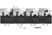
画像のシーケンスは、道路網を通る車両の動きを反映する。すなわち、シーケンス内の各画像は、特定の時点および特定のカメラ位置における道路網の環境を表す。好ましくは、画像のシーケンスはビデオシーケンスを含む。したがって、画像は、ビデオシーケンスのそれぞれのフレームに対応することができる。したがって、1つ以上のカメラは1つ以上のビデオカメラを含むことができ、好ましい実施形態では含む。 The sequence of images reflects the movement of vehicles through the road network. That is, each image in the sequence represents the environment of the road network at a particular point in time and a particular camera position. Preferably, the sequence of images comprises a video sequence. Thus, an image can correspond to each frame of a video sequence. Accordingly, the one or more cameras may, and in preferred embodiments include, one or more video cameras.
実施形態では、1つ以上のステレオカメラを使用して、複数の画像(のうちの少なくともいくつか)を取得することができる。しかし、ステレオカメラの使用は必要ではなく、いくつかの実施形態では、画像が(単に)1つ以上の単眼カメラまたは単一のカメラを使用して取得されてもよい。いくつかの好ましい実施形態では、1つ以上のカメラが1つ以上のステレオカメラおよび1つ以上の単一(単眼)カメラを含むことができる。例えば、実施形態では、以下に説明するように、ステレオカメラを使用して得られた複数のステレオ画像を、ビジュアルオドメトリの目的に有利に使用することができる。しかし、画像内のオブジェクトを識別し分類する目的のために、単一の(単眼)カメラから得られた画像を使用することが好ましい場合がある。 In embodiments, one or more stereo cameras may be used to acquire (at least some of) multiple images. However, the use of stereo cameras is not required and in some embodiments the images may be (simply) acquired using one or more monocular cameras or a single camera. In some preferred embodiments, the one or more cameras may include one or more stereo cameras and one or more single (monocular) cameras. For example, in embodiments, multiple stereo images obtained using a stereo camera may be advantageously used for visual odometry purposes, as described below. However, it may be preferable to use images obtained from a single (monocular) camera for the purpose of identifying and classifying objects in the images.
画像データは、所望に応じて、様々な他のセンサからのデータによって補足されてもよい。例えば、GNSSデータなどの位置データを使用して、車両の粗い位置特定および画像の各々のタイムスタンプを提供することができる。 Image data may be supplemented by data from various other sensors as desired. For example, location data, such as GNSS data, can be used to provide a coarse localization of the vehicle and a timestamp for each image.
画像シーケンス内の画像は一般に、(例えば、道路網を通る車両、したがって、関連する1つまたは複数のカメラの動き(移動)を反映して)異なる位置で取得されるので、画像を一緒に処理して、車両が走行しているエリアの一貫したローカル地図表現を生成するために、画像のそれぞれに関連するカメラ位置を知る(または少なくとも判定することができる)ことが必要である。すなわち、各画像は、エリアのある部分の2次元ビューを表す。したがって、エリア全体の一貫したビューを生成するためには、異なる画像からの異なるビューを一緒に集約する必要がある。これは、画像が記録された位置の知識に基づいて行うことができる。例えば、オブジェクトは一般に、2次元点のセットとして任意の所与の画像に現れることが理解されるだろう。一連の画像が記録されると、同じオブジェクトが複数の画像に現れるが、異なる視点から見ることができる。これは、例えば、三角測量を使用して、オブジェクトを位置特定することを可能にするものである。しかし、一貫したローカル地図表現を生成するために、例えば道路網内のオブジェクトの相対的な位置および向きを示すために、オブジェクトを画像から所望の3次元座標フレームにマッピングすることができるように、異なる画像を取得するために使用されるカメラの位置および向き(一緒に、「ポーズ」)を考慮に入れなければならない。すなわち、異なる位置で記録された一連の画像から一貫したローカル地図表現を生成するためには、異なる画像のカメラ位置を知るか、または判定する必要がある。 Since the images in the image sequence are generally acquired at different positions (e.g., reflecting the movement (movement) of the vehicle through the road network and thus the associated camera or cameras), the images are processed together. As such, it is necessary to know (or at least be able to determine) the camera position associated with each of the images in order to generate a consistent local map representation of the area in which the vehicle is traveling. That is, each image represents a two-dimensional view of some portion of the area. Therefore, different views from different images need to be aggregated together to generate a consistent view of the entire area. This can be done based on knowledge of the location where the image was recorded. For example, it will be appreciated that objects generally appear in any given image as a set of two-dimensional points. When a series of images is recorded, the same object appears in multiple images but can be viewed from different viewpoints. This allows objects to be localized, for example using triangulation. However, in order to generate a consistent local map representation, e.g., to show the relative position and orientation of objects within a road network, so that objects can be mapped from the image into a desired three-dimensional coordinate frame, The position and orientation (together, "pose") of the camera used to acquire the different images must be taken into account. That is, in order to generate a consistent local map representation from a series of images recorded at different locations, it is necessary to know or determine the camera positions of the different images.
画像が記録された位置(または「カメラ位置」)は、絶対位置として提供されてもよく、画像が配置された地点における道路網内のカメラの絶対位置および向き(姿勢)を表す。したがって、実施形態では、本技法は画像の絶対カメラ位置を取得することを含む。しかし、これは、常に利用可能であるとは限らない非常に高精度のセンサを必要とする場合がある。例えば、画像の各々は、例えば、GNSS又は他の位置データを使用して取得されるときに位置スタンプされてもよく、従って、絶対位置は例えば、高精度オドメータ及び/又はGNSSデータを使用することによって、そのような位置データを使用して直接取得されてもよい。多くの場合、そのようなGNSSまたは他の位置データの精度は、(特に、車両が非常に正確に位置特定されることが不可欠である自律運転のために)位置特定の十分に高度な判定を、位置特定のために信頼性を持って使用することを可能にしないことがある。したがって、(各)画像のカメラ位置がシーケンス内の1つ以上の他の画像に対して提供されるように、カメラ位置を相対位置として提供することができ、次いで、相対カメラ位置を使用して、画像を一緒に集約して、エリアのローカル地図表現を生成する。1つの画像から次の画像へのカメラ位置の相対変化は一般に、車両のオドメトリを使用して(すなわち、車両に関連する1つ以上のオドメトリセンサを使用して)判定することができる。例えば、シーケンス内の第1の画像に対する初期カメラ位置は、例えばGNSS又は他の位置データから(比較的高い精度で)知ることができる。次いで、第1の画像と比較されたシーケンス内の後続の画像の相対位置は、車両のオドメトリに基づいて、すなわち、道路網を通る車両の移動の知識に基づいて判定され得る。したがって、実施形態では、本技法は、シーケンス内の第1の画像などの基準画像に対する画像のうちの少なくともいくつかの相対カメラ位置を判定することを含む。 The position where the image was recorded (or "camera position") may be provided as an absolute position, representing the absolute position and orientation (orientation) of the camera within the road network at the point where the image was placed. Thus, in embodiments, the technique includes obtaining an absolute camera position for the image. However, this may require very precise sensors that are not always available. For example, each of the images may be position-stamped when acquired using, for example, GNSS or other position data, so absolute position can be obtained using, for example, high-precision odometer and/or GNSS data. may be obtained directly using such location data by . In many cases, the accuracy of such GNSS or other location data is not sufficient to allow sufficiently sophisticated determination of location (especially for autonomous driving where it is essential that the vehicle is located very accurately). , may not allow it to be used reliably for localization. Thus, the camera position can be provided as a relative position, such that the camera position of (each) image is provided with respect to one or more other images in the sequence, and then using the relative camera position , aggregate the images together to generate a local map representation of the area. Relative changes in camera position from one image to the next can generally be determined using vehicle odometry (ie, using one or more odometry sensors associated with the vehicle). For example, the initial camera position for the first image in the sequence may be known (with relatively high accuracy), eg from GNSS or other position data. The relative position of subsequent images in the sequence compared to the first image can then be determined based on the vehicle's odometry, ie knowledge of the vehicle's movement through the road network. Thus, in embodiments, the technique includes determining relative camera positions of at least some of the images with respect to a reference image, such as the first image in the sequence.
異なる画像の(相対的な)カメラ位置は、任意の適切な所望の技法を使用して判定することができる。例えば、ステレオ画像が得られる場合、様々な既知のステレオ画像位置合わせ技術を用いて、例えば、連続する奥行き画像を位置合わせすることによって、画像の相対的なカメラ位置を導出することができる。しかし、好ましくは、画像の(相対的な)カメラ位置は、ビジュアルオドメトリのプロセスによって判定される。すなわち、画像の相対的なカメラ位置は、画像の処理から(例えば、純粋に)視覚的に判定されてもよい。例えば、ビジュアルオドメトリは、基準画像に対する画像の回転および位置(すなわち、画像またはカメラ「ポーズ」)を判定するために使用されてもよく、基準画像は、典型的にはカメラの初期位置が一般に知られていてもよい画像シーケンスの最初の画像である。したがって、実施形態では、シーケンス内の画像の画像ポーズが、第1(基準)画像を記録するために使用されるカメラの初期位置に対して判定される。ポーズは、一連の画像内の記録された画像毎に判定されてもよい。しかし、一般に、ポーズを判定するだけでよく、ポーズは、実施形態では、「キーフレーム」と呼ばれる画像(またはフレーム)のサブセット、すなわち、以前に取得された画像に対して著しいカメラの動きおよび/または画像内容の変化を示す画像、についてのみ判定される。したがって、各画像(またはキーフレーム)について、第1(基準)画像に対する画像の回転および位置を表す相対姿勢が生成される。(「キーフレーム」という概念は一般的に、例えばビデオ符号化において十分理解される。一般に、画像のシーケンスを処理するための本明細書の任意の基準は、画像のすべて、または画像のいくつかのみ、例えばキーフレームのみを処理することを含んでもよい。あるいは、画像のシーケンスがキーフレームのシーケンスを含んでもよい。) The (relative) camera positions of the different images can be determined using any suitable desired technique. For example, if stereo images are obtained, the relative camera positions of the images can be derived using various known stereo image registration techniques, eg, by registering successive depth images. Preferably, however, the (relative) camera positions of the images are determined by a process of visual odometry. That is, the relative camera positions of the images may be determined visually (eg, purely) from processing the images. For example, visual odometry may be used to determine the rotation and position of an image (i.e., an image or camera "pose") relative to a reference image, which typically has a commonly known initial camera position. is the first image in the image sequence that may be Thus, in embodiments, the image poses of the images in the sequence are determined with respect to the initial position of the camera used to record the first (reference) image. A pose may be determined for each recorded image in the sequence of images. In general, however, we only need to determine the pose, which in the embodiment is a subset of images (or frames) called "keyframes", i.e. significant camera movements and/or or images showing changes in image content. Thus, for each image (or keyframe) a relative pose is generated that represents the rotation and position of the image with respect to the first (reference) image. (The concept of a "keyframe" is generally well understood, e.g., in video coding. In general, any criterion herein for processing a sequence of images can be either all of the images or some of the images. may involve processing only, e.g., keyframes only, or a sequence of images may include a sequence of keyframes.)
GNSSまたは他の位置データはビジュアルオドメトリを補足するために使用されてもよい。例えば、各画像(またはキーフレーム)について、粗いカメラ位置がGNSSまたは他の位置データから推定されてもよく、次いで、これはシーケンス内の他の画像に基づいてビジュアルオドメトリを使用して洗練されてもよい。 GNSS or other location data may be used to supplement visual odometry. For example, for each image (or keyframe), a coarse camera position may be estimated from GNSS or other position data, which is then refined using visual odometry based on other images in the sequence. good too.
ビジュアルオドメトリの原理は十分に確立されており、一般に、任意の適切かつ所望のビジュアルオドメトリ技術を本発明と共に使用することができる。典型的なビジュアルオドメトリ技術は「動きからの構造」の仮定に基づいているが、他の構成、例えば、各種ステレオグラフィ技術も可能である。ビジュアルオドメトリは単一のカメラ(または単眼)画像データを使用して実行することができるが、好ましくはビジュアルオドメトリに使用される画像は1つ以上のステレオカメラを使用して取得され、その結果、例えば、画像の画像深度が既知であり、ビジュアルオドメトリアルゴリズムへの入力として提供することができる(そうでなければ、これらを何らかの形で推定または判定しなければならないことになり、これは、移動車両からオンザフライ(無線)で画像が生成されるときは困難かもしれない。したがって、実施形態では、任意の適切かつ所望のステレオビジュアルオドメトリ技法を使用することができる。 The principles of visual odometry are well established and, in general, any suitable and desired visual odometry technique can be used with the present invention. Although typical visual odometry techniques are based on the "structure from motion" assumption, other configurations are possible, such as various stereographic techniques. Although visual odometry can be performed using single camera (or monocular) image data, preferably the images used for visual odometry are acquired using one or more stereo cameras, so that For example, the image depth of the image is known and can be provided as an input to the visual odometry algorithm (otherwise they would have to be estimated or determined somehow, which would be useful for moving vehicles). It may be difficult when the images are generated on-the-fly (over the air) from a .Thus, embodiments may use any suitable and desired stereovisual odometry technique.
ビジュアルオドメトリは例えば、既知のバンドル調整技術を用いて間接的に実行されてもよい。しかしながら、好ましくは、ステレオダイレクトスパースオドメトリ(DSO)技術が画像ポーズを得るために使用される。DSOはカメラ上へのオブジェクトの投射間の測光誤差の直接最小化に基づく既知の技法であり、オブジェクトは、基準フレーム内のキーポイントのセットおよび奥行きによって暗黙的に定義される。したがって、基準フレームから次のフレームにオブジェクトを投影または追跡するために、キーポイントは次のフレームに投影され、複数のキーポイントの測光誤差は基準フレームから次のフレームに移動するための適切な変換を判定するために最小化される。したがって、変換はフレーム間の位置および回転の変化を示し、すなわち、カメラまたは画像ポーズを決定することができる。オリジナルのDSO技術は、単眼画像に基づいていた。DSOプロセスの詳細は、参照arXiv:1607.02565でarXiv.org上で入手可能なEngelらによる「Direct Sparse Odometry」に見出すことができ、その全内容は参照により本明細書に組み込まれる。しかし、好ましい実施形態はステレオ画像に基づくステレオDSO技法を使用し、その結果、画像深度をDSOアルゴリズムへの入力として提供して、(一般に、(DSOの場合)既に正しい深度推定値を有する既存の画像を必要とする)トラッキングプロセスを改善することができる。したがって、ステレオDSOプロセスの出力は、第1(基準)画像と比較した各画像に対する相対姿勢(ポーズ)である。ステレオDSOプロセスのさらなる詳細は、参照arXiv:1708.07878でarXiv.org上で入手可能なWangらによる「Stereo DSO: Large-Scale Direct Sparse Visual Odometry with stereo Cameras」に見出すことができ、その全内容は参照により本明細書に組み込まれる。 Visual odometry may be performed indirectly using known bundle adjustment techniques, for example. Preferably, however, a stereo direct sparse odometry (DSO) technique is used to obtain the image poses. DSO is a known technique based on direct minimization of photometric errors between projections of an object onto a camera, where the object is implicitly defined by a set of keypoints and depth in a reference frame. Therefore, to project or track an object from a reference frame to the next frame, the keypoints are projected to the next frame, and the photometric error of multiple keypoints is the appropriate transformation to move from the reference frame to the next frame. is minimized to determine Therefore, the transform describes changes in position and rotation between frames, ie camera or image pose can be determined. The original DSO technology was based on monocular images. Details of the DSO process can be found in reference arXiv:1607.02565 in arXiv. org, "Direct Sparse Odometry" by Engel et al., the entire contents of which are incorporated herein by reference. However, the preferred embodiment uses a stereo DSO technique based on stereo images, so that the image depth is provided as an input to the DSO algorithm (generally (in the case of DSO) existing image) can be improved. The output of the stereo DSO process is therefore the relative pose for each image compared to the first (reference) image. Further details of the stereo DSO process can be found in reference arXiv:1708.07878 in arXiv. ``Stereo DSO: Large-Scale Direct Sparse Visual Odometry with stereo Cameras'' by Wang et al., available on www.org, the entire contents of which are incorporated herein by reference.
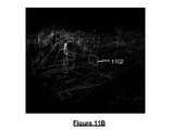
ステレオDSOプロセスの出力はまた、一般に、処理されているフレームの各々についての「キーポイントクラウド(キー点群)」(本明細書では「スパースポイントクラウド(疎点群)」とも呼ばれる)を含む。疎点群は、各画像内の各種キーポイントの位置を表す。上述したように、キーポイントは、カメラ画像上へのオブジェクトの2次元投影を含む。疎点群はまた、画像内の画素の各々について推定された深さ(デプス)を含む。 The output of a stereo DSO process also typically includes a "keypoint cloud" (also referred to herein as a "sparse point cloud") for each frame being processed. The sparse point cloud represents the locations of various keypoints within each image. As mentioned above, a keypoint includes a two-dimensional projection of an object onto the camera image. The sparse point cloud also includes an estimated depth for each pixel in the image.
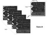
画像をより良好に処理することができるようにするために、また、例えば、画像に現れるオブジェクトを自動的に検出または抽出するために、複数の異なる「オブジェクトクラス」のうちの1つ以上に従って画像の要素を分類するために、セマンティックセグメンテーションのステップを実行することができる。他の構成も可能であるが、典型的には画像内の個々の画素の各々が分類されるように、画像は画素単位でセグメント化される。したがって、実施形態では、画像内の各画素に対してオブジェクトクラスまたはクラスのリスト(および関連する確率)を割り当てるために、画像の少なくともいくつか(たとえば、少なくともキーフレーム)を処理することができる。一般に、画像データを処理し分類するために、任意の適切かつ所望のセマンティックセグメンテーションプロセスを使用することができる。好ましい実施形態では、画像のセマンティックセグメンテーションは機械学習アルゴリズムを使用して実行される。例えば、いわゆる「SegNet」または「PSPNet」システムなどの訓練された畳み込みニューラルネットワーク、またはその修正を、画像データのセグメント化および分類のために適切に使用することができる。オブジェクトクラスは一般に、セマンティックセグメンテーションアルゴリズム内で定義され、例えば、「道路」、「空」、「車両」、「交通標識」、「交通信号」、「交通信号灯」、「レーンマーキング」などのオブジェクトクラスを含むことができる。SegNetおよびPSPNetは、両方とも、特に道路網の画像を分類するために開発された既知のアルゴリズムである。したがって、上述のような適切なオブジェクトクラスは、これらのアルゴリズムにおいて既に定義されている。SegNetアーキテクチャのさらなる詳細は、参照arXiv:1511.00561でarXiv.org上で入手可能な、Badrinarayananらによる「SegNet: A Deep Convolutional Encoder-Decoder Architecture for Image Segmentation」に見出すことができ、その全内容は、参照により本明細書に組み込まれる。PSPNetアーキテクチャのさらなる詳細は、参照arXiv:1612.01105でarXiv.org上で入手可能な、Zhaoらによる「Pyramid Scene Parsing Network」に見出すことができ、その全内容は、参照により本明細書に組み込まれる。 In order to be able to process images better, and for example to automatically detect or extract objects appearing in an image, images can be processed according to one or more of a number of different "object classes". A semantic segmentation step can be performed to classify the elements of . Typically, the image is segmented on a pixel-by-pixel basis so that each individual pixel in the image is classified, although other configurations are possible. Accordingly, embodiments may process at least some of the images (eg, at least the keyframes) to assign an object class or list of classes (and associated probabilities) to each pixel in the image. In general, any suitable and desired semantic segmentation process can be used to process and classify the image data. In a preferred embodiment, semantic segmentation of images is performed using machine learning algorithms. For example, trained convolutional neural networks, such as the so-called "SegNet" or "PSPNet" systems, or modifications thereof, can be suitably used for segmentation and classification of image data. Object classes are generally defined within semantic segmentation algorithms, for example object classes such as "road", "sky", "vehicle", "traffic sign", "traffic light", "traffic light", "lane marking", etc. can include Both SegNet and PSPNet are known algorithms developed specifically for classifying images of road networks. Therefore, the appropriate object classes as described above are already defined in these algorithms. Further details of the SegNet architecture can be found in reference arXiv:1511.00561 in arXiv. org, "SegNet: A Deep Convolutional Encoder-Decoder Architecture for Image Segmentation" by Badrinarayanan et al., the entire contents of which are incorporated herein by reference. Further details of the PSPNet architecture can be found in reference arXiv:1612.01105 at arXiv. Zhao et al., "Pyramid Scene Parsing Network" available on org, the entire contents of which are incorporated herein by reference.
各画素には、セマンティックセグメンテーションに基づいて(単一の)オブジェクトクラスを割り当てることができる。しかし、実施形態では、各画素にはオブジェクトクラスベクトルが割り当てられ、ベクトル要素は複数の異なるオブジェクトクラスのそれぞれに属するその画素の尤度(または確率)を表す。 Each pixel can be assigned a (single) object class based on semantic segmentation. However, in embodiments, each pixel is assigned an object class vector, the vector elements representing the likelihood (or probability) of that pixel belonging to each of a number of different object classes.
このセマンティックセグメンテーションのステップは、画像が複数の一般的な車両環境オブジェクトクラスに従って分類されるので、「車両環境」セマンティックセグメンテーションと呼ぶことができる。 This semantic segmentation step can be referred to as "vehicle environment" semantic segmentation, as the images are classified according to several general vehicle environment object classes.
一般に、セマンティックセグメンテーションのこのステップは、上述のビジュアルオドメトリのステップの前または後に、またはそれと並行して実行されてもよい。 In general, this step of semantic segmentation may be performed before, after, or in parallel with the step of visual odometry described above.
機械学習技術はセマンティックセグメンテーションを実行するために使用される必要はなく、他の実施形態では、画像は、代替的に、または追加的に、例えばステレオカメラを使用するときに利用可能な画像深度データを使用して、例えば、画像内のそれらの相対的な深度に基づいて画素を分類するために処理されてもよいことが理解されるだろう。例えば、このようにして、例えば、ステレオ点群を使用して、画像は、グランド(地面)レベル画素、壁/ハウジング、交通標識ポールなどにセグメント化されてもよい。別の例として、画像セグメンテーションは、上述のDSO点群などの疎特徴点群データを使用することができ、これを使用して、例えば、「グランド(地面)レベル」点(のみ)を含む粗グランド(地面)マスクを生成することができる。 Machine learning techniques need not be used to perform semantic segmentation; in other embodiments, images may alternatively or additionally utilize image depth data available, for example when using stereo cameras. may be processed, for example, to classify pixels based on their relative depth within the image. For example, in this way, for example using a stereo point cloud, the image may be segmented into ground level pixels, walls/housings, traffic sign poles, etc. As another example, image segmentation can use sparse feature point cloud data, such as the DSO point cloud described above, which can be used, for example, to generate a coarse feature containing (only) "ground level" points. A ground mask can be generated.
例えば、上述のアルゴリズムを使用して、一旦、画像がこのように分類されると(、セマンティックセグメンテーションから判定された1つまたは複数のオブジェクトクラスは、オブジェクトクラスの特定のサブセットのみを使用し得る、任意の後続の処理ステップのために利用可能にされ得る。例えば、あるオブジェクトクラスに対応する画像内の任意の要素が抽出され、または一緒にグループ化され、その後、他の要素とは別個に処理されてもよい。例えば、ランドマーク観察特徴を作成するために、以下でさらに説明するように、システムは一般に、「ランドマーク」タイプのオブジェクトクラスが割り当てられた画素または画素のグループを考慮するだけでよい。(セマンティックセグメンテーションは、一般的な「ランドマーク」クラスを含まないことができ、一般的には含まず、むしろ、それぞれが一般的に異なるタイプの「ランドマーク」を示す「建物」クラス、「交通標識」クラスなどのいくつかのクラスを含むことができることを理解されたい。したがって、本明細書のランドマーククラスへの参照は、複数のランドマークタイプクラスの何れか1つを意味するものとして理解すべきである。) For example, using the algorithm described above, once the image is classified in this way (one or more object classes determined from the semantic segmentation may use only a particular subset of object classes, can be made available for any subsequent processing step, e.g., any elements in the image that correspond to an object class are extracted or grouped together and then processed separately from other elements For example, to create landmark observation features, the system generally only considers pixels or groups of pixels that have been assigned an object class of type "landmark", as described further below. (A semantic segmentation may not include a generic 'landmark' class, nor does it typically include a 'building' class, each generally representing a different type of 'landmark'. , the "traffic sign" class, etc. Thus, references herein to a landmark class mean any one of a plurality of landmark type classes. should be understood as a thing.)
したがって、同じオブジェクトクラス内の任意の画素を一緒に抽出または処理して、オブジェクト「フィルタリングされた」画像を生成することができる。同様に、同じクラス内の隣接画素のグループは、特徴または「オブジェクト」として一緒に関連付けることができ、次いで、それらを互いに独立して抽出し、後続の処理ステップで使用することができる。 Therefore, any pixels within the same object class can be extracted or processed together to produce an object "filtered" image. Similarly, groups of adjacent pixels within the same class can be associated together as features or "objects", which can then be extracted independently of each other and used in subsequent processing steps.
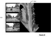
実施形態では、画像のうちの少なくともいくつかは、ローカル地図表現に含めるための1つ以上のランドマークオブジェクト特徴を検出(および抽出)するために処理される。一般に、ランドマークオブジェクト特徴は、道路網の環境を示し、または道路網の環境に特徴的である任意の特徴であって、例えば、ローカル地図表現の基準地図セクションとのマッチングおよび/または位置合わせを容易にするために、ローカル地図表現に適切かつ望ましく組み込まれ得る任意の特徴を含み得る。例えば、画像コンテンツは一般に、画像を得るために使用される1つ又は複数のカメラの視野内にある何らかのオブジェクトを含み、これらのオブジェクトの何れも、原則として、所望により、画像から抽出することができる。しかし、適切に抽出され、ローカル地図表現に組み込まれ得る典型的なランドマークオブジェクトは、建物、交通標識、交通信号、広告板などの特徴を含み得る。 In embodiments, at least some of the images are processed to detect (and extract) one or more landmark object features for inclusion in the local map representation. In general, a landmark object feature is any feature that indicates or is characteristic of the environment of the road network, e.g. To facilitate, it may include any features that may be suitable and desirably incorporated into the local map representation. For example, image content generally includes any object within the field of view of one or more cameras used to obtain the image, any of which in principle can be extracted from the image if desired. can. However, typical landmark objects that can be adequately extracted and incorporated into the local map representation can include features such as buildings, traffic signs, traffic lights, billboards, and the like.
一般に、ランドマークオブジェクトは例えば、各種の自動視覚的特徴検出技術を使用して、任意の適切かつ所望の方法で画像内で検出することができる。しかしながら、実施形態において、ランドマークオブジェクト特徴は、上述の車両環境セマンティックセグメンテーションによって割り当てられた1つ又は複数のオブジェクトクラスを使用して検出されてもよい。例えば、ランドマークに対応するオブジェクトクラスが割り当てられた画像内の任意の画素、または画素のグループは関心領域、すなわち、(潜在的に)ランドマークを含み得る領域であるとして、そのベースに基づいて識別され得る。このようにして、セマンティックセグメンテーションを直接使用して、画像内の各種ランドマークオブジェクトを検出し、識別することができる。例えば、セマンティックセグメンテーション中に判定されたオブジェクトクラス(またはクラスベクトル)を使用して、例えばランドマークオブジェクトクラスが割り当てられた画像内の関心のある任意の領域(または画素)を画像から抽出することができる。次いで、1つ又は複数の関心領域は、画像または各画像における1つ以上のランドマークの境界を検出するために、さらに処理されてもよい。例えば、処理されている各画像について、検出された1つ以上のランドマークを含む1つ以上の境界エリアのリストを生成することができる。 In general, landmark objects can be detected in images in any suitable and desired manner, for example using various automatic visual feature detection techniques. However, in embodiments, landmark object features may be detected using one or more object classes assigned by the vehicle environment semantic segmentation described above. For example, any pixel or group of pixels in an image that is assigned an object class corresponding to a landmark is a region of interest, i.e., a region that may (potentially) contain a landmark, and on that basis can be identified. In this way, semantic segmentation can be used directly to detect and identify various landmark objects in images. For example, the object class (or class vector) determined during semantic segmentation can be used to extract from the image any region of interest (or pixel) in the image that has been assigned, for example, the landmark object class. can. The one or more regions of interest may then be further processed to detect boundaries of one or more landmarks in the or each image. For example, for each image being processed, a list of one or more bounding areas containing one or more detected landmarks can be generated.
上述のように、車両環境セマンティックセグメンテーションの第1のステップが画像に対して実行され、1つ以上の関心領域が第1のセマンティックセグメンテーションに基づいてランドマークオブジェクトを潜在的に含むものとして判定された後、セマンティックセグメンテーションの第2のまたはさらなるステップ(またはオブジェクト検出および分類)が、判定された関心領域に対して特に実行されてもよい。すなわち、さらなる特定の分類ステップが、ランドマーク分類をさらに洗練するために、ランドマークを含むと判定された任意の関心領域に対して実行されてもよい。すなわち、1つ以上のランドマークが画像内で検出されると、ランドマーク認識のさらなる特定のステップを実行することができる。換言すれば、元の画像データからの画素は、まず、車両環境セマンティックセグメンテーションからの複数の一般的なオブジェクトクラスに従って分類されてもよい。元の画像データから検出された任意のランドマークについて、さらなる特定のランドマーク認識分類を実行して、ランドマーク検出を洗練することができる。例えば、ランドマーク認識は、検出されたランドマークの各々に関連する境界を洗練するために使用されてもよい。 As described above, a first step of vehicle environment semantic segmentation was performed on the image, and one or more regions of interest were determined as potentially containing landmark objects based on the first semantic segmentation. Later, a second or further step of semantic segmentation (or object detection and classification) may be performed specifically on the determined region of interest. That is, further specific classification steps may be performed on any region of interest determined to contain a landmark to further refine the landmark classification. That is, once one or more landmarks are detected in the image, further specific steps of landmark recognition can be performed. In other words, the pixels from the original image data may first be classified according to multiple general object classes from the vehicle environment semantic segmentation. For any landmarks detected from the original image data, further specific landmark recognition classification can be performed to refine landmark detection. For example, landmark recognition may be used to refine the boundaries associated with each detected landmark.
さらなるセマンティックセグメンテーションを構成することができるランドマーク認識は、(必ずしも必要ではないが)第1の(車両環境)セマンティックセグメンテーションとほぼ同様の方法で実行することができる。典型的には、機械学習アルゴリズムが使用される。例えば、実施形態では、サポートベクターマシンまたはニューラルネットワークなどの教師付き学習方法を使用して、ランドマーク認識セマンティックセグメンテーションを実行することができる。しかし、ランドマーク認識の目的のために、アルゴリズムは例えば、一般的な車両環境セマンティックセグメンテーションを使用して達成されるよりも、より特定的で正確なランドマーク分類を提供するように、特定のランドマークデータを使用して訓練されてもよい。 Landmark recognition, from which further semantic segmentations can be constructed, can (though not necessarily) be performed in much the same way as the first (vehicle environment) semantic segmentation. Typically machine learning algorithms are used. For example, embodiments may perform landmark recognition semantic segmentation using supervised learning methods such as support vector machines or neural networks. However, for the purpose of landmark recognition, the algorithm may, for example, use specific landmarks to provide more specific and accurate landmark classification than is achieved using general vehicle environment semantic segmentation. It may be trained using mark data.
検出される(しかし、画像のうちの1つ以上においてこれは行われる)任意のランドマークオブジェクトについて、次いで、ローカル地図表現内に含めるために、ランドマーク観察特徴を作成することができる。すなわち、ローカル地図表現が生成されると、検出されたランドマークを表す特徴が、ローカル地図表現に含まれてもよい。ランドマーク観察特徴は、典型的には、ランドマーク位置と、ランドマーク方向(向き)と、ランドマーク形状とを含む。したがって、実施形態では、本技法は、画像のシーケンスを処理して、画像のうちの1つ以上に現れる1つ以上のランドマークオブジェクトを検出することと、検出されたランドマークオブジェクトごとに、ローカル地図表現に含めるためのランドマーク観察を生成することとを含むことができ、ランドマーク観察は検出されたランドマークの位置および向きを示す情報を含む。検出されたランドマークの位置および向きを示す情報は一般に、ランドマークの相対位置および向きを含むことができる。例えば、検出されたランドマークの位置および向きは、一般に、例えばビジュアルオドメトリから判定されるような、例えば車両の動きフレームに基づいて、道路網自体、または車両に対する(いずれかの)相対的な位置および向きを含むことができる。例えば、実施形態では、2次元ランドマーク形状、例えば、ポリラインを、2次元ランドマーク形状をローカル地図表現に組み込むのに適した3次元空間に変換するための配向行列と共に、各ランドマークについて生成することができる。したがって、コンテンツを記述する画像ファイルを生成して、ローカル地図表現に含めることができる。 For any landmark object that is detected (but this is done in one or more of the images), a landmark viewing feature can then be created for inclusion within the local map representation. That is, once the local map representation is generated, features representing detected landmarks may be included in the local map representation. Landmark viewing features typically include landmark position, landmark direction (orientation), and landmark shape. Thus, in embodiments, the techniques process a sequence of images to detect one or more landmark objects appearing in one or more of the images; and generating a landmark sighting for inclusion in the map representation, the landmark sighting including information indicative of the location and orientation of the detected landmark. Information indicative of the position and orientation of detected landmarks may generally include the relative position and orientation of the landmarks. For example, the position and orientation of a detected landmark is generally determined relative to (either) the road network itself or the vehicle, for example based on the vehicle's motion frame, for example as determined from visual odometry. and orientation. For example, embodiments generate a 2D landmark shape, e.g., a polyline, for each landmark, along with an orientation matrix for transforming the 2D landmark shape into a 3D space suitable for incorporation into a local map representation. be able to. Accordingly, an image file describing the content can be generated and included in the local map representation.
一般に、先に述べたように、同じオブジェクト(例えば、ランドマーク)は画像のシーケンスにおいて複数回現れるが、多くの異なる視点から見られる。したがって、例えば、道路網内(または車両に対する)のランドマークの位置および向きを判定することができるように、複数の画像からの情報を一緒に集約するために、ランドマークをローカル地図表現に組み込むことができるように、一般に、(例えば、ビジュアルオドメトリを使用して判定することができるように)ランドマークが検出された画像の各々についてのカメラ姿勢(ポーズ)を知ることが必要である。したがって、ランドマーク観察は、典型的には一連の画像(少なくともいくつか)、ならびにランドマーク認識(これが実行される場合)から生じる境界エリアおよびオブジェクトクラス、ならびにランドマークが検出された画像についてのカメラ姿勢(ポーズ)を使用して生成される。次いで、ランドマークの位置および向きは、例えば、オブジェクト姿勢推定のための既知のビジュアルオドメトリ技法を使用して、カメラ姿勢に基づいて任意の適切な方法で判定され得る。例えば、一般に、ランドマークの位置および向きは、複数の画像および当該画像が取得された関連するカメラ位置を使用して三角測量に基づいて判定されてもよい。したがって、実施形態では、本技法は、画像のうちの少なくともいくつかを処理して、画像に現れる1つ以上のランドマークオブジェクトを検出することと、検出されたランドマークごとに、ローカル地図表現に含めるためのランドマーク観察を生成することとを含み、ランドマーク観察は検出されたランドマークの位置および向きを示す情報を含み、検出されたランドマークの位置および向きはランドマークが検出された複数の画像およびそれに関連するカメラ位置を使用して三角測量によって判定される。 Generally, as mentioned above, the same object (eg, landmark) appears multiple times in a sequence of images, but is viewed from many different perspectives. Thus, for example, landmarks are incorporated into a local map representation in order to aggregate information from multiple images together so that the position and orientation of the landmark within the road network (or relative to the vehicle) can be determined. As can be done, it is generally necessary to know the camera pose for each image in which landmarks are detected (as can be determined using, for example, visual odometry). Therefore, landmark observation typically consists of a sequence of images (at least some), as well as the bounding area and object class resulting from landmark recognition (if this is performed), and camera Generated using poses. The position and orientation of the landmark may then be determined in any suitable manner based on the camera pose, for example using known visual odometry techniques for object pose estimation. For example, in general, the position and orientation of landmarks may be determined based on triangulation using multiple images and the associated camera positions from which the images were acquired. Thus, in embodiments, the techniques process at least some of the images to detect one or more landmark objects appearing in the images; and generating a landmark observation for inclusion, the landmark observation including information indicative of the position and orientation of the detected landmark, the position and orientation of the detected landmark being the plurality of landmarks at which the landmark was detected. is determined by triangulation using the image of and its associated camera position.
いくつかの実施形態では、車両のオドメトリ(移動量)を判定する目的のため、およびランドマークおよびレーンマーキングなどの特徴を検出するために、異なるカメラを使用することができる。例えば、実施形態では、1つ以上のステレオカメラがビジュアルオドメトリのために使用されてもよく、一方、1つ以上の単一(モノ)カメラが特徴検出のために使用される。この場合、オドメトリ転送のステップは、ビジュアルオドメトリの結果に基づいて、例えば、これらの画像をビジュアルオドメトリプロセスに使用される画像の回転および/または平行移動として扱うことによって、ランドマーク検出に使用される画像の姿勢(ポーズ)を判定するために実行されてもよい。異なるカメラがビジュアルオドメトリおよび特徴検出のために使用される実施形態では、第1のカメラはモノクロカメラであってもよく、第2のカメラはマルチクロム(またはカラー)カメラであってもよい。例えば、1つ以上のモノクロカメラはビジュアルオドメトリのための(モノクロ)画像を取得するために使用されてもよく、一方、1つ以上のマルチクロムカメラは特徴検出のための(カラー)画像を取得するために使用されてもよい。 In some embodiments, different cameras may be used for purposes of determining vehicle odometry and for detecting features such as landmarks and lane markings. For example, in embodiments one or more stereo cameras may be used for visual odometry, while one or more single (mono) cameras are used for feature detection. In this case, the odometry transfer step is used for landmark detection based on the visual odometry results, e.g., by treating these images as rotations and/or translations of the images used in the visual odometry process. It may also be performed to determine the pose of the image. In embodiments where different cameras are used for visual odometry and feature detection, the first camera may be a monochrome camera and the second camera may be a multi-chrome (or color) camera. For example, one or more monochrome cameras may be used to acquire (monochrome) images for visual odometry, while one or more multichrom cameras acquire (color) images for feature detection. may be used to
ランドマークを検出することができ、且つランドマーク観察を生成することができる精度を向上させるために、検出されたランドマークオブジェクトは、画像のシーケンス内で注意深く追跡され、次いで、あらゆる誤検出を識別(およびフィルタ除去)しようと試みるために、異なる画像からの他の検出(すなわち、同じランドマークオブジェクトの)と比較され得る。例えば、ランドマークオブジェクト(交通標識など)が1つのフレームに現れる場合、ランドマークは隣接する画像、すなわち、ランドマークが検出された画像の両側にも現れることが予想される。他方、不正確な又は偽陽性検出の場合、これは当てはまらない。したがって、各画像内の各ランドマークオブジェクト検出について、検出されたランドマークは、隣接する画像の範囲内(シーケンス内で前方および後方)で、その透視歪みに関して注意深く追跡することができる。トラッキング(追跡)は一般に、異なる画像の(以前に決定された、または既知の)相対位置および姿勢(ポーズ)に基づいて、任意の適切な動きモデルを使用して実行されてもよい。例えば、実施形態では、Kanade-Lucas-Tomasi(KLT)特徴トラッカを使用することができる。実施形態では、従来のアフィン変換KLTトラッカを使用する代わりに、KLTトラッカのホモグラフィ拡張(HKLT)を使用することができる。追跡の結果はランドマークが検出された画像から、画像の相対姿勢に基づく画像の範囲への、検出されたランドマークの理想的なマッピングを記述する透視変換のセットからなる。したがって、このマッピングは、現実世界(3次元)空間内の検出されたランドマークの表現を、シーケンス内の画像の範囲を通って延びる「トラック(軌跡)」の形で与える。次に、これは、検出されたランドマークを三次元空間で三角測量することを可能にし、例えば、車両のオドメトリの座標系におけるランドマークの三角測量された輪郭を与える。これらのステップは、各フレームにおいて検出された各ランドマークについて実行されてもよい。したがって、これは、検出された各ランドマーク(すなわち、ランドマークが検出された各フレームに対して1つ)に対して多くの三角測量された輪郭をもたらし、これらの輪郭は(追跡品質に応じて)大まかに重なる。次いで、3次元(3D)表現をグループ化し、任意の外れ値を除去することができる。したがって、このグループ化は、偽陽性検出、または他の不正確なランドマーク検出が、3次元空間に散乱する傾向があるのに対して、真のランドマークはフレームごとに3次元空間に並ぶ傾向があるので、偽陽性フィルタを提供する。したがって、実施形態では、本技法は、画像内の1つ以上のランドマークオブジェクトを検出するために画像の少なくとも一部を処理することと、画像シーケンスの各画像で検出された各ランドマークオブジェクトについて、それが検出された画像から検出されたランドマークを画像シーケンスの1つ以上の隣接する画像にマッピングするための変換のセットを、画像の関連するカメラ位置を使用して判定することと、画像シーケンスの各画像で検出された各ランドマークオブジェクトについて、3次元座標空間におけるランドマークの表現を、マッピングに基づいて生成することと、各グループが同じ物理的ランドマークに対応するが異なる画像に記録された3次元表現のセットを含むように、3次元表現を一緒にグループ化することとを含むことができる。 In order to improve the accuracy with which landmarks can be detected and landmark observations generated, the detected landmark objects are carefully tracked within the sequence of images, and any false detections are then identified. (and filtering out) can be compared with other detections (ie of the same landmark object) from different images. For example, if a landmark object (such as a traffic sign) appears in one frame, it is expected that the landmark will also appear in adjacent images, ie on both sides of the image in which the landmark is detected. On the other hand, this is not the case for inaccurate or false positive detection. Thus, for each landmark object detection in each image, the detected landmark can be carefully tracked with respect to its perspective distortion within adjacent images (forward and backward in the sequence). Tracking may generally be performed using any suitable motion model based on the (previously determined or known) relative positions and poses of the different images. For example, embodiments may use the Kanade-Lucas-Tomasi (KLT) feature tracker. In embodiments, instead of using a conventional affine transform KLT tracker, a homography extension of the KLT tracker (HKLT) can be used. The result of the tracking consists of a set of perspective transformations that describe the ideal mapping of the detected landmarks from the image in which the landmarks were detected to the extent of the image based on the relative pose of the images. This mapping thus gives a representation of the detected landmarks in real-world (three-dimensional) space in the form of "tracks" extending through the extent of the images in the sequence. This then allows the detected landmarks to be triangulated in three-dimensional space, giving, for example, the triangulated contours of the landmark in the coordinate system of the vehicle's odometry. These steps may be performed for each landmark detected in each frame. This therefore results in many triangulated contours for each detected landmark (i.e. one for each frame in which the landmark is detected), and these contours can be (depending on the tracking quality) ) roughly overlap. The three-dimensional (3D) representations can then be grouped and any outliers removed. This grouping therefore suggests that false-positive detections, or other inaccurate landmark detections, tend to be scattered in three-dimensional space, whereas true landmarks tend to line up in three-dimensional space from frame to frame. provides a false-positive filter because there is Thus, in embodiments, the techniques include processing at least a portion of an image to detect one or more landmark objects in the image; , using the associated camera positions of the images, determining a set of transformations for mapping the detected landmark from the image in which it was detected to one or more adjacent images of the image sequence; For each landmark object detected in each image of the sequence, generating a representation of the landmark in the three-dimensional coordinate space based on the mapping, each group corresponding to the same physical landmark but recorded in different images. grouping together the three-dimensional representations to include a set of three-dimensional representations.
ランドマークを識別するためのこの方法は新規であり、それ自体が有利であると考えられる。 This method for identifying landmarks is believed to be novel and advantageous in its own right.
したがって、本発明の更なる態様によれば、道路網の環境内の1つ以上のランドマークを識別する方法であって、
前記道路網を走行する車両と関連付けられた1つ以上のカメラから、前記車両が走行している前記道路網の前記環境を反映する一連の画像を取得することであって、前記画像の各々は、前記画像が記録された関連するカメラ位置を有する、前記取得することと、
前記画像内の1つ以上のランドマークオブジェクトを検出するために前記画像の少なくともいくつかを処理することであって、前記ランドマークオブジェクトは、前記道路網の前記環境におけるランドマークを表す、前記処理することと、
前記一連の画像の各画像において検出された各ランドマークオブジェクトについて、前記画像の前記関連するカメラ位置を使用して、前記検出されたランドマークオブジェクトを、当該ランドマークオブジェクトが検出された前記画像から前記一連の画像の1つ以上の隣接する画像にマッピングするための変換のセットを判定することと、
前記一連の画像の各画像において検出された各ランドマークオブジェクトについて、3次元座標空間における前記ランドマークオブジェクトの表現を生成することと、
前記環境内の同じランドマークに対応する異なる画像から生成された3次元表現のセットを判定することと、
3次元表現の前記判定されたセットから、3次元表現の前記セットによって表される前記環境内の前記ランドマークを示すデータを生成することと、
を含む方法が提供される。Thus, according to a further aspect of the invention, a method of identifying one or more landmarks in a road network environment, comprising:
obtaining from one or more cameras associated with vehicles traveling on the road network a series of images reflective of the environment of the road network on which the vehicle is traveling, each of the images comprising: , said obtaining having an associated camera position at which said image was recorded;
processing at least some of the images to detect one or more landmark objects in the images, wherein the landmark objects represent landmarks in the environment of the road network. and
for each landmark object detected in each image of the sequence of images, using the associated camera position of the image to locate the detected landmark object from the image in which it was detected; determining a set of transforms for mapping to one or more adjacent images of the series of images;
generating, for each landmark object detected in each image of the sequence of images, a representation of the landmark object in a three-dimensional coordinate space;
determining a set of three-dimensional representations generated from different images corresponding to the same landmark in the environment;
generating data from the determined set of three-dimensional representations indicative of the landmarks in the environment represented by the set of three-dimensional representations;
A method is provided comprising:
この態様による方法は、本発明の他の態様および実施形態に関連して上述した特徴のいずれかを含むことができる。例えば、トラッキングは一般に、KLTトラッカ、または同様のものを使用して、上述のように実行され得る。 Methods according to this aspect may include any of the features described above in relation to other aspects and embodiments of the invention. For example, tracking can generally be performed as described above using a KLT tracker, or the like.
本発明はまた、本発明のこの態様による方法、または本明細書に記載されるその実施形態のいずれかを実行するためのシステムにも及ぶ。 The invention also extends to a system for carrying out the method according to this aspect of the invention, or any of its embodiments described herein.
従って、別の態様からは、道路網の環境内の1つ以上のランドマークを識別するシステムであって、
前記道路網を走行する車両と関連付けられた1つ以上のカメラから、前記車両が走行している前記道路網の前記環境を反映する一連の画像を取得する手段であって、前記画像の各々は、前記画像が記録された関連するカメラ位置を有する、前記取得する手段と、
前記画像内の1つ以上のランドマークオブジェクトを検出するために前記画像の少なくともいくつかを処理する手段であって、前記ランドマークオブジェクトは、前記道路網の前記環境内のランドマークを表す、前記処理する手段と、
前記一連の画像の各画像において検出された各ランドマークオブジェクトについて、前記画像の前記関連するカメラ位置を使用して、前記検出されたランドマークオブジェクトを、当該ランドマークオブジェクトが検出された前記画像から前記一連の画像の1つ以上の隣接する画像にマッピングするための変換のセットを判定する手段と、
前記一連の画像の各画像において検出された各ランドマークオブジェクトについて、3次元座標空間における前記ランドマークオブジェクトの表現を生成する手段と、
前記環境内の同じランドマークに対応する異なる画像から生成された3次元表現のセットを判定する手段と、
3次元表現の前記判定されたセットから、3次元表現の前記セットによって表される前記環境内の前記ランドマークを示すデータを生成する手段と、
を備えるシステムが提供される。Thus, from another aspect, a system for identifying one or more landmarks in a road network environment comprising:
means for obtaining, from one or more cameras associated with vehicles traveling on said road network, a series of images reflective of said environment of said road network on which said vehicle is traveling, each of said images comprising: , the obtaining means having an associated camera position at which the image was recorded;
means for processing at least some of said images to detect one or more landmark objects in said images, said landmark objects representing landmarks in said environment of said road network; means for processing;
for each landmark object detected in each image of the sequence of images, using the associated camera position of the image to locate the detected landmark object from the image in which it was detected; means for determining a set of transforms for mapping to one or more adjacent images of said sequence of images;
means for generating, for each landmark object detected in each image of said sequence of images, a representation of said landmark object in three-dimensional coordinate space;
means for determining a set of three-dimensional representations generated from different images corresponding to the same landmark in the environment;
means for generating, from the determined set of three-dimensional representations, data indicative of the landmarks in the environment represented by the set of three-dimensional representations;
A system is provided comprising:
本発明のこのさらなる態様は必要に応じて、本発明の任意の他の態様または実施形態に関して本明細書に記載される本発明の好ましい特徴および任意選択の特徴のうちの任意の1つまたは複数またはすべてを含むことができ、好ましくは含む。例えば、明示的に述べられていなくても、本明細書に記載の方法に関連して説明した任意のステップを、その態様または実施形態のいずれにおいても実施するための手段を含むことができ、その逆もまた同様である。該方法または装置に関連して説明したステップのいずれかを実行するための手段は、1つ以上のプロセッサおよび/または処理回路を含むことができる。したがって、本発明は好ましくはコンピュータによって実施される発明であり、本発明の態様または実施形態のいずれかに関して説明されるステップのいずれかは、1つまたは複数のプロセッサおよび/または処理回路のセットの制御下で実行され得る。 This further aspect of the invention optionally includes any one or more of the preferred and optional features of the invention described herein with respect to any other aspect or embodiment of the invention. or all of them, and preferably all of them. for example, even if not explicitly stated, can include means for performing any step described in connection with the methods described herein in any of its aspects or embodiments; The opposite is also true. Means for performing any of the steps described in connection with the method or apparatus may include one or more processors and/or processing circuits. Accordingly, the present invention is preferably a computer-implemented invention and any of the steps described with respect to any aspect or embodiment of the invention may be performed by one or more processors and/or sets of processing circuits. It can be run under control.
異なる画像から3次元表現をグループ化した結果、グループの各々は実質的に重複する表現のセットを含み、これにより、複数の異なるフレームで検出された同じ物理的ランドマークに関連付けることができる。すなわち、同じ物理的ランドマークに関連する任意の3次元表現は一般に、座標空間内で並ぶことが予想され、したがって、これに基づいて一緒にグループ化することができる。しかし、不正確な検出に基づく任意の3次元表現は、座標空間内に散乱して現れ、したがって、外れ値として破棄され得る(グループには含まれない)。したがって、グループ化はランドマークのより正確な識別を提供するために、任意の偽陽性または他の不正確なランドマーク検出が除去されることを可能にする。 As a result of grouping 3D representations from different images, each group contains a set of substantially overlapping representations, which can be associated with the same physical landmarks detected in different frames. That is, any 3D representations that relate to the same physical landmark are generally expected to line up in coordinate space and can therefore be grouped together on this basis. However, any 3D representation based on inaccurate detection will appear scattered in the coordinate space and can therefore be discarded as an outlier (not included in the group). Grouping therefore allows any false positives or other inaccurate landmark detections to be eliminated in order to provide more accurate identification of landmarks.
次いで、各グループ内の3次元表現を融合して、ランドマークの単一の2次元輪郭を判定し、かつ/または座標空間内のランドマークの再構成を生成することができる。融合された3次元輪郭はランドマークをより正確に位置決めし、各画像(フレーム)から切り出すことを可能にすることができる。カットアウト(切り抜き)を重ねることによって、標識の融合画像を生成することができる。このようにして、オクルージョンまたは鏡面ハイライトのような欠陥をランドマークの画像から除去することができ、例えば、カットアウト(切り抜き)間の高い色分散を有する画素をマスキングすることによって、ランドマークの境界をより確実に検出することも可能である。マスクされたカットアウト(切り抜き)の画素輪郭は、車両のオドメトリに対するランドマーク形状、画素内容、および位置のより正確な3次元表現を提供するようにベクトル化することができる。次いで、この正確な表現は例えば、画像から得られた表現を基準地図内の基準ランドマーク形状と関連付けることによって、位置特定のために使用することができる。 The 3D representations within each group can then be fused to determine a single 2D contour of the landmark and/or generate a reconstruction of the landmark in coordinate space. The fused 3D contour can allow landmarks to be more accurately positioned and cropped from each image (frame). By overlapping the cutouts, a fused image of the sign can be generated. In this way, defects such as occlusions or specular highlights can be removed from images of landmarks, for example by masking pixels with high chromatic dispersion between cutouts. It is also possible to detect boundaries more reliably. Pixel contours of masked cutouts can be vectorized to provide a more accurate three-dimensional representation of landmark shapes, pixel contents, and locations for vehicle odometry. This accurate representation can then be used for localization, for example, by associating the representation obtained from the image with the reference landmark shape in the reference map.
本方法によって生成された環境中のランドマークを示すデータは本明細書では「ランドマーク観察」とも呼ばれ、好ましくは、環境中のランドマークの位置、環境中のランドマークの向き、ランドマークの形状を表す2次元(2D)ポリライン、2Dポリラインに適用されたときにポリラインを3D座標空間(環境を表す)に変換する姿勢行列、および2Dポリラインに含まれるコンテンツを記述する画像のうちの少なくとも1つ、いくつか、またはすべてである。 Data indicative of landmarks in the environment generated by the method are also referred to herein as "landmark observations" and preferably include the position of the landmarks in the environment, the orientation of the landmarks in the environment, the orientation of the landmarks At least one of a two-dimensional (2D) polyline representing a shape, a pose matrix that when applied to the 2D polyline transforms the polyline into a 3D coordinate space (representing the environment), and an image that describes the content contained in the 2D polyline. one, some, or all.
実施形態では、「グランド(地面)メッシュ」が画像のシーケンスから生成される。例えば、「グランド(地面)メッシュ」画像は、車両が走行しているエリア内のグランド(地面)レベルの特徴(のみ)を含むように生成されてもよい。グランド(地面)メッシュは例えば、グランド(地面)レベルオブジェクトクラス(「道路」、「道路マーキング」、「レーンマーキング」など)が割り当てられた任意の画素を抽出するか、または使用することによって、車両環境セマンティックセグメンテーションから取得されたオブジェクトクラスを使用して生成され得る。しかし、セマンティックセグメンテーションは完全ではなく、場合によっては、セマンティックセグメンテーションがいくつかの誤った値を与えることがあり、すなわち、いくつかの点を、それらがグランド(地面)上にない場合であっても、グランド(地面)レベル点として選択することがある。したがって、実施形態では、グランド(地面)メッシュ生成の精度を向上させるために、点群を使用して、地点をさらにフィルタリングまたは選択することができる。点群は、単独で、または好ましくは車両環境セマンティックセグメンテーションからのオブジェクトクラスと組み合わせて使用することができる。例えば、グランド(地面)メッシュは、上述のDSOプロセスからの出力として疎点群を使用して生成されてもよい。しかし、代替的に、または追加的に、グランド(地面)メッシュは、画素深度を使用してステレオ画像から直接得られるステレオ点群を使用して生成されてもよい。例えば、DSO点群の疎性のために、DSO点群を補うためにステレオ点群を使用することが有益であり得る。例えば、ステレオ点群は、DSO点群内に不十分なデータが存在する高度を補間するために使用されてもよく、そうでなければDSO点群を使用してもよい。あるいは、DSO点群が疎すぎる場合、DSO点群の代わりにステレオ点群を使用することができる。一般に、グランド(地面)メッシュを生成するために、様々な適切な技術が考えられる。 In an embodiment, a "ground mesh" is generated from the sequence of images. For example, a "ground mesh" image may be generated to include (only) ground level features within the area in which the vehicle is traveling. A ground mesh can be created, for example, by extracting or using any pixel assigned a ground level object class ("road", "road marking", "lane marking", etc.). It can be generated using object classes obtained from environment semantic segmentation. However, the semantic segmentation is not perfect, and in some cases the semantic segmentation may give some wrong values, i.e. some points are not on the ground , may be chosen as ground level points. Therefore, in embodiments, the point cloud may be used to further filter or select points in order to improve the accuracy of ground mesh generation. Point clouds can be used alone or preferably in combination with object classes from vehicle environment semantic segmentation. For example, a ground mesh may be generated using the sparse point cloud as output from the DSO process described above. However, alternatively or additionally, the ground mesh may be generated using a stereo point cloud obtained directly from the stereo images using pixel depth. For example, due to the sparsity of the DSO point cloud, it may be beneficial to use the stereo point cloud to supplement the DSO point cloud. For example, the stereo point cloud may be used to interpolate altitudes where there is insufficient data in the DSO point cloud, otherwise the DSO point cloud may be used. Alternatively, if the DSO point cloud is too sparse, a stereo point cloud can be used instead of the DSO point cloud. In general, various suitable techniques are conceivable for generating the ground mesh.
次に、グランド(地面)メッシュを使用して、道路網のグランド(地面)レベル特徴のオルソ補正画像を生成することができる。一般的に言えば、オルソ補正された画像は「スケール補正された」画像であり、それらの正確なグランド(地面)位置において上方から見たグランド(地面)特徴を描写し、好ましくは、カメラおよび飛行特性および起伏(レリーフ)変位によって引き起こされる歪みが写真測量技術を使用して除去されている。オルソ補正された画像は、写真のスケールが均一であるように幾何学的に補正された(「オルソ補正された」)一種の航空写真であり、これは、写真が地図と同等であると考えることができることを意味する。オルソ補正された画像は、地形起伏、レンズ歪み、およびカメラ傾斜に対して調整された、地球の表面の正確な表現であるので、真の距離を測定するために使用することができる。オルソ補正されたビューは基準平面に対して直角に投影され、一方、パースペクティブビューは、単一の固定位置から基準平面上に表面から投影されるので、オルソ補正されたビューはパースペクティブビューとは異なる。オルソ補正された画像は、任意の適切な地図投影によって得ることができる。地図投影は、円筒形、擬似円筒形、ハイブリッド、円錐形、擬似円錐形、または方位角などの表面による投影とすることができる。投影は、メトリック特性の保存による投影であってもよい。地図投影はそれらが直交投影であることが一般的であり、それは、全ての画素がその表面に垂直な線に沿って見られる基準平面(地球の形に近似する楕円)の表面上の点を表すことを意味する。したがって、地球表面のオルソ補正画像のすべての画素は、地球の形状に近似する楕円体に垂直な線に沿って見た地球表面のビューに実質的に対応する。オルソ補正された画像は、アルゴリズムがオルソ補正された画像の任意の画素を地理的座標基準システム内の点に対して参照することを可能にするメタデータを含む。各画素の地球の形状に近似する楕円体上の正確な位置が分かっているので、グランド(地面)特徴、例えば水平道路情報の位置およびサイズをオルソ補正画像から導出することができる。 The ground mesh can then be used to generate an orthorectified image of the ground level features of the road network. Generally speaking, orthorectified images are "scale-corrected" images, depicting ground features viewed from above at their exact ground position, preferably the camera and Distortions caused by flight characteristics and relief displacements have been removed using photogrammetric techniques. An orthorectified image is a type of aerial photograph that has been geometrically corrected ("orthorectified") so that the scale of the photograph is uniform, which considers the photograph to be equivalent to a map. means that you can An orthorectified image is an accurate representation of the earth's surface, adjusted for terrain relief, lens distortion, and camera tilt, so it can be used to measure true distances. The orthorectified view differs from the perspective view because the orthorectified view is projected perpendicular to the reference plane, while the perspective view is projected from the surface onto the reference plane from a single fixed position. . The orthorectified image can be obtained by any suitable map projection. Map projections can be cylindrical, pseudo-cylindrical, hybrid, conical, pseudo-conical, or surface projections such as azimuth. The projection may be a projection with preservation of metric properties. Map projections are generally those that are orthogonal projections, which represent points on the surface of a reference plane (an ellipse that approximates the shape of the Earth) with all pixels viewed along a line perpendicular to that surface. means to represent Therefore, every pixel of an orthorectified image of the Earth's surface corresponds substantially to a view of the Earth's surface along a line perpendicular to an ellipsoid that approximates the shape of the Earth. The orthorectified image contains metadata that allows the algorithm to reference any pixel of the orthorectified image to a point in the geographic coordinate reference system. Knowing the exact location of each pixel on an ellipsoid that approximates the shape of the earth, the location and size of ground features, such as horizontal road information, can be derived from the orthorectified image.
実施形態では、オルソ補正された道路画像は、画像から抽出された特徴がグランド(地面)メッシュ上に投影されて一緒にブレンドされる、車両が走行しているエリアのトップダウンビューを含む鳥瞰モザイクを含むことができる。例えば、記録された画像の各々をグランド(地面)に投影して戻すことができる。したがって、画像に関連するカメラ姿勢の知識を使用して、多くの異なる視点からグランド(地面)に画像を投影することが可能である。これは、複数の異なる画像に対して行うことができ、次いで、様々な異なる視点から得られる投影を重ね合わせ、一緒にブレンドすることができる。したがって、投影画像のすべてをグランド(地面)上に重ね合わせることによって、グランド(地面)の外観を再生成する画像が生成され、この画像は所望の任意の視点から見ることができる(例えば、鳥瞰図)。代替的に、または追加的に、オルソ補正された道路画像は、例えば鳥瞰モザイクから判定されるような、真っ直ぐにされた移動のビューを含む直線的に変換(位置合わせ)された画像を含むことができる。直線的に変換された画像(LRI)の生成は、典型的にはカメラの軌道(すなわち、車両の自身の動き)に垂直な当該軌道に沿った等間隔のスライスを生成することを含むことができる。LRIの生成に関するさらなる詳細は「Method of capturing linear features and a reference-line across a surface for a map database」と題する国際公開第 2009/045096 号に見出すことができ、その全内容は参照により本明細書に組み込まれる。次いで、任意の点で高さをサンプリングすることができるように、グランド(地面)メッシュの高さ地図を生成することができる。次いで、線形位置合わせ画像は、上述したのと同様の方法で、スライスに沿ってサンプル高さ地図を生成し、サンプル点を見るカメラ画像上に各サンプル点を投影し、次いで画素値を適切に平均してブレンド画像を生成することによって、グランド(地面)上にカメラ画像を投影することによってレンダリングすることができる。オルソ補正された道路画像を生成する際に、車両環境セマンティックセグメンテーションから判定され得る、任意の異質のまたは望ましくない特徴(例えば、車両のボンネット)を除去するために、画像マスクが使用され得る。 In an embodiment, the orthorectified road image is a bird's-eye mosaic containing a top-down view of the area the vehicle is traveling in, where features extracted from the image are projected onto a ground mesh and blended together. can include For example, each recorded image can be projected back onto the ground. Therefore, using knowledge of the camera pose associated with the image, it is possible to project the image onto the ground from many different viewpoints. This can be done for multiple different images, and then the projections from various different viewpoints can be superimposed and blended together. Thus, superimposing all of the projected images onto the ground produces an image that recreates the appearance of the ground, which can be viewed from any perspective desired (e.g., bird's eye view). ). Alternatively or additionally, the orthorectified road image comprises a rectilinearly transformed (registered) image containing a straightened movement view, e.g. determined from a bird's eye mosaic. can be done. Generating a linearly transformed image (LRI) can typically involve generating equally spaced slices along the trajectory of the camera (i.e., the vehicle's own motion) perpendicular to the trajectory. can. Further details regarding the generation of LRIs can be found in WO 2009/045096 entitled "Method of capturing linear features and a reference-line across a surface for a map database", the entire contents of which are incorporated herein by reference. incorporated into. A height map of the ground mesh can then be generated so that the height can be sampled at any point. The linearly registered image is then produced by generating a sample height map along the slice, projecting each sample point onto the camera image looking at the sample point, and then converting the pixel values appropriately It can be rendered by projecting the camera image onto the ground by averaging to produce a blended image. An image mask may be used to remove any extraneous or undesirable features (e.g., the hood of the vehicle) that may be determined from the vehicle environment semantic segmentation when generating the orthorectified road image.
実施形態では、オルソ補正された道路画像が生成され、画像内の各画素の画素値は、道路画像を生成するために使用される画像から検出される環境内の位置の色を表す。従って、各画素値は好ましくは複数の値、例えば、赤-緑-青(RGB)色空間を使用する場合には3つの値を有するベクトルを含む。 In an embodiment, an orthorectified road image is generated, the pixel value of each pixel in the image representing the color of the location in the environment detected from the image used to generate the road image. Therefore, each pixel value preferably comprises a vector with multiple values, eg, three values when using the red-green-blue (RGB) color space.
さらに、または代替として、オルソ補正された道路画像が生成され、画像内の各画素の画素値は、車両環境セマンティックセグメンテーションからの出力として、環境内の位置がレーンマーキングオブジェクトである確率を表す。例えば、グレースケール色空間を使用する場合、レーンマーキングオブジェクトである100%の確率が割り当てられた任意の画素は「白」であってもよく、0%の確率を有する任意の画素は「黒」であってもよく、他の画素値はそれぞれの確率に基づいて適切に選択される。このようにして、レーンマーキングオブジェクトを強調表示し、レーンマーキングセマンティックセグメンテーションを実行するためのより明瞭な画像を提供する、「フィルタリングされた」グレースケール正投影道路画像を生成することができる。次いで、この画像は特定のレーンマーキングタイプクラスに従って画素を分類するためにレーンマーキングセマンティックセグメンテーションの特定のステップを受けることができ、または、例えば、訓練された畳み込みニュートラルネットを使用して、レーンマーキングオブジェクト検出および認識を受けることができ、画像内のオブジェクトを特定のタイプのレーンマーキングとして識別および分類することができる。レーンマーキングクラスの例は、単一の実線、単一の短い破線、単一の長い破線、二重の実線、二重の破線、アイランド境界などのうちの1つ以上を含むことができる。 Additionally or alternatively, an orthorectified road image is generated and the pixel value of each pixel in the image represents the probability that the location in the environment is a lane marking object as output from the vehicle environment semantic segmentation. For example, when using a grayscale color space, any pixel assigned a 100% probability of being a lane marking object may be "white" and any pixel with a 0% probability may be "black". , and other pixel values are appropriately selected based on their respective probabilities. In this way, a “filtered” grayscale orthographic road image can be generated that highlights lane marking objects and provides a clearer image for performing lane marking semantic segmentation. This image can then undergo a specific step of lane marking semantic segmentation to classify pixels according to a specific lane marking type class or, for example, using a trained convolutional neutral net, the lane marking object It can be detected and recognized, and objects in the image can be identified and classified as particular types of lane markings. Examples of lane marking classes may include one or more of a single solid line, a single short dashed line, a single long dashed line, a double solid line, a double dashed line, an island boundary, and the like.
レーン幾何形状を識別するこの方法は新規であり、それ自体有利であると考えられる。 This method of identifying lane geometry is believed to be novel and advantageous in its own right.
したがって、本発明の更なる態様によれば、道路網の1つ以上の道路上のレーンマーキングの位置および幾何形状を判定する方法であって、
前記道路網を走行する車両と関連付けられた1つ以上のカメラから、前記車両が走行している前記道路網の環境を反映する一連の画像を取得することであって、前記画像の各々は、前記画像が記録された関連するカメラ位置を有する、前記取得することと、
処理された画像の各画素が少なくとも、前記画素が前記環境内のレーンマーキングを表す確率値を割り当てられるように、セマンティックセグメンテーションを実行するために前記画像の少なくともいくつかを処理することと、
前記車両が走行している前記道路網のエリアを表す道路画像を生成するために前記一連の画像のうち少なくともいくつかの画像を処理することであって、前記道路画像内の各画素の画素値は、前記道路画像を生成するために使用される前記画像内の対応する画素の前記割り当てられた確率値に基づくものである、前記処理することと、
前記画像内の1つ以上のレーンマーキングオブジェクトを検出および分類するために前記道路画像を処理することであって、前記レーンマーキングオブジェクトは、前記道路画像に描かれた前記1つ以上の道路上のレーンマーキングを表す、前記処理することと、
前記検出及び分類されたレーンマーキングオブジェクトを使用して、前記レーンマーキングオブジェクトによって表される前記レーンマーキングの前記位置および幾何形状を判定するために前記道路画像を処理することと、
を含む方法が提供される。Thus, according to a further aspect of the invention, a method of determining the position and geometry of lane markings on one or more roads of a road network comprising:
acquiring, from one or more cameras associated with vehicles traveling on the road network, a series of images reflective of the environment of the road network on which the vehicle is traveling, each of the images comprising: said obtaining having an associated camera position at which said image was recorded;
processing at least some of the images to perform semantic segmentation such that each pixel of the processed image is at least assigned a probability value that the pixel represents a lane marking in the environment;
processing at least some of said series of images to generate a road image representing an area of said road network on which said vehicle is traveling, said pixel value of each pixel in said road image; is based on the assigned probability values of corresponding pixels in the image used to generate the road image;
processing the road image to detect and classify one or more lane marking objects in the image, the lane marking objects on the one or more roads depicted in the road image; representing lane markings;
using the detected and classified lane marking objects to process the road image to determine the location and geometry of the lane markings represented by the lane marking objects;
A method is provided comprising:
この態様による方法は一般に、少なくとも相互に排他的ではない範囲で、本発明の他の態様および実施形態に関して上述した特徴のいずれかを含むことができることが理解されるだろう。 It will be appreciated that methods according to this aspect can generally include any of the features described above with respect to other aspects and embodiments of the invention, at least to the extent they are not mutually exclusive.
本発明はまた、本発明のこの態様による方法、または本明細書に記載されるその実施形態のいずれかを実行するためのシステムにも及ぶ。 The invention also extends to a system for carrying out the method according to this aspect of the invention, or any of its embodiments described herein.
従って、さらなる態様からは、道路網の1つ以上の道路上のレーンマーキングの位置及び幾何形状を判定するシステムであって、
前記道路網を走行する車両と関連付けられた1つ以上のカメラから、前記車両が走行している前記道路網の環境を反映する一連の画像を取得する手段であって、前記画像の各々は、前記画像が記録された関連するカメラ位置を有する、前記取得する手段と、
処理された画像の各画素が少なくとも、前記画素が前記環境内のレーンマーキングを表す確率値を割り当てられるように、セマンティックセグメンテーションを実行するために前記画像の少なくともいくつかを処理する手段と、
前記車両が走行している前記道路網のエリアを表す道路画像を生成するために前記一連の画像の前記画像のうち少なくともいくつかの画像を処理する手段であって、前記道路画像内の画素毎の画素値は、前記道路画像を生成するために使用される前記画像内の対応する画素の前記割り当てられた確率値に基づくものである、前記処理する手段と、
前記画像内の1つ以上のレーンマーキングオブジェクトを検出及び分類するために前記道路画像を処理する手段であって、前記レーンマーキングオブジェクトは、前記道路画像に描かれた前記1つ以上の道路上のレーンマーキングを表す、前記処理する手段と、
前記検出及び分類されたレーンマーキングオブジェクトを使用して、前記レーンマーキングオブジェクトによって表される前記レーンマーキングの前記位置及び幾何形状を判定するために前記道路画像を処理する手段と、
を備えるシステムが提供される。Thus, from a further aspect, a system for determining the position and geometry of lane markings on one or more roads of a road network comprising:
means for acquiring, from one or more cameras associated with vehicles traveling on said road network, a series of images reflective of the environment of said road network on which said vehicles are traveling, each of said images comprising: said acquiring means having an associated camera position at which said image was recorded;
means for processing at least some of said images to perform semantic segmentation such that each pixel of the processed image is at least assigned a probability value that said pixel represents a lane marking in said environment;
means for processing at least some of said images of said sequence of images to generate a road image representative of an area of said road network on which said vehicle is traveling, said means for processing at least some of said images of said series of images to generate a road image representing an area of said road network on which said vehicle is traveling; pixel values of are based on the assigned probability values of corresponding pixels in the image used to generate the road image;
means for processing said road image to detect and classify one or more lane marking objects in said image, said lane marking objects being on said one or more roads depicted in said road image; said means for processing representing lane markings;
means for processing the road image to determine the location and geometry of the lane markings represented by the lane marking objects using the detected and classified lane marking objects;
A system is provided comprising:
本発明のこのさらなる態様は必要に応じて、本発明の任意の他の態様または実施形態に関して本明細書に記載される本発明の好ましい特徴および任意選択の特徴のうちの任意の1つまたは複数またはすべてを含むことができ、好ましくは含む。例えば、明示的に述べられていなくても、本明細書に記載の方法に関連して説明した任意のステップを、その態様または実施形態のいずれにおいても実施するための手段を含むことができ、その逆もまた同様である。該方法または装置に関連して説明したステップのいずれかを実行するための手段は、1つ以上のプロセッサおよび/または処理回路を含むことができる。したがって、本発明は好ましくはコンピュータによって実施される発明であり、本発明の態様または実施形態のいずれかに関して説明されるステップのいずれかは、1つまたは複数のプロセッサおよび/または処理回路のセットの制御下で実行され得る。 This further aspect of the invention optionally includes any one or more of the preferred and optional features of the invention described herein with respect to any other aspect or embodiment of the invention. or all of them, and preferably all of them. for example, even if not explicitly stated, can include means for performing any step described in connection with the methods described herein in any of its aspects or embodiments; The opposite is also true. Means for performing any of the steps described in connection with the method or apparatus may include one or more processors and/or processing circuits. Accordingly, the present invention is preferably a computer-implemented invention and any of the steps described with respect to any of the aspects or embodiments of the invention may be performed by one or more processors and/or sets of processing circuits. It can be run under control.
したがって、さらなるセマンティックセグメンテーションステップを含むことができる、レーンマーキング検出および分類から得られる識別されたレーンマーキングを使用して、ローカル地図表現に組み込むためのレーンマーキング観察(観測)を作成することができる。例えば、レーンマーキング観察は、車両が走行している道路網のエリア内の検出されたレーンマーキングオブジェクトを含むことができる。したがって、レーン幾何形状は、ローカル地図表現(および/またはそれに基づいて更新する場合には基準地図)に組み込むことができる。 Thus, the identified lane markings resulting from lane marking detection and classification, which can include an additional semantic segmentation step, can be used to create lane marking observations (observations) for incorporation into local map representations. For example, lane marking observations may include detected lane marking objects within the area of the road network on which the vehicle is traveling. Thus, lane geometry can be incorporated into the local map representation (and/or the reference map if updating based on it).
上述したように、グランド(地面)メッシュおよびオルソ補正された道路画像は、レーン観察を生成するために使用される。しかし、グランド(地面)メッシュおよび/またはオルソ補正された道路画像は、単に視覚化の目的のために生成されてもよく、必ずしもレーン観察特徴生成の後続のステップで使用される必要はないことが理解されるだろう。 As described above, the ground mesh and orthorectified road images are used to generate lane observations. However, it should be noted that the ground mesh and/or orthorectified road image may be generated solely for visualization purposes and need not necessarily be used in subsequent steps of lane observation feature generation. will be understood.
本発明によれば、ローカル地図表現は、取得された画像の少なくともいくつかおよび関連するカメラ位置を使用する。ローカル地図表現は一般に、車両が走行している道路網のエリアを表す。実施形態では、ローカル地図表現は道路網のエリアのオルソ補正画像を含むことができ、これは実質的に上述のように生成することができる。好ましくは、ローカル地図表現は、上述したように、グランド(地面)メッシュおよび/またはオルソ補正された道路画像を含む。原則として、ローカル地図表現は、グランド(地面)メッシュおよび/またはオルソ補正された道路画像のみを含むことができる。しかし、好ましくは、ローカル地図表現は、上述したように、レーン観察およびランドマーク観察の一方または両方も含む。例えば、レーンマーキングオブジェクト及び/又はランドマークは、グランド(地面)メッシュ及び/又はオルソ補正された道路画像に適切に埋め込まれて、ローカル地図表現を構築することができる。あるいは、ローカル地図表現は、例えば、グランド(地面)メッシュおよび/またはオルソ補正された道路画像なしで、レーン観察およびランドマーク観察の一方または両方を含む。 According to the invention, the local map representation uses at least some of the captured images and associated camera positions. A local map representation generally represents the area of the road network on which the vehicle is traveling. In embodiments, the local map representation may include an orthorectified image of an area of the road network, which may be generated substantially as described above. Preferably, the local map representation includes a ground mesh and/or an orthorectified road image, as described above. In principle, the local map representation can only contain ground meshes and/or orthorectified road images. Preferably, however, the local map representation also includes one or both of lane observations and landmark observations, as described above. For example, lane marking objects and/or landmarks can be appropriately embedded in ground meshes and/or orthorectified road images to build a local map representation. Alternatively, the local map representation includes one or both of lane and landmark views, eg, without a ground mesh and/or orthorectified road image.
したがって、生成されるローカル地図表現は一般に、車両が走行しているエリア内の道路網および道路網の環境の画像を含む。ローカル地図表現は、そのエリア内の道路網の環境を示すトップダウン2次元画像を含むことができる。しかし、ローカル地図表現は、そのエリア内の道路網の環境を示す3次元画像を含むこともできる。ローカル地図表現はまた、画像に埋め込まれた、または画像の上にある1つ以上の特徴を含むことができる。場合によっては、ローカル地図表現は、1つ以上の「キー」画像(またはフレーム)を含むこともできる。例えば、ローカル地図表現は、車両に関連付けられたカメラから取得された複数の画像のうちの1つ以上を含むことができる。 Therefore, the local map representation generated generally includes an image of the road network and the environment of the road network within the area in which the vehicle is traveling. A local map representation may include a top-down two-dimensional image showing the environment of the road network within the area. However, the local map representation can also include a three-dimensional image showing the environment of the road network within the area. A local map representation can also include one or more features embedded in or overlying the image. In some cases, the local map representation may also include one or more "key" images (or frames). For example, the local map representation may include one or more of multiple images obtained from a camera associated with the vehicle.
ローカル地図表現は、生成されると、次に、基準地図セクションと比較されるか、またはマッチングされる。基準地図セクションは、少なくとも、車両が走行している道路網のエリア、すなわち、画像が取得されたエリアをカバーする区間である。原則として、比較は、内部地図レポジトリ内の(グローバル)全体地図に基づいて行うことができる。しかし、実際には、基準地図セクションは、例えば、GNSSまたは他の位置データを使用して得ることができるような、車両の位置の近似または粗い知識に基づいて、または以前の位置特定結果から、選択することができる。したがって、基準地図セクションのエリアは、車両が(現在)走行している道路網のエリアに実質的にまたはおおよそ対応することができる。 Once the local map representation is generated, it is then compared or matched with the reference map section. A reference map section is a section that covers at least the area of the road network on which the vehicle is traveling, i.e. the area where the image was acquired. In principle, the comparison can be based on the (global) global map in the internal map repository. However, in practice, the reference map section is based on an approximation or coarse knowledge of the vehicle's position, such as can be obtained using GNSS or other location data, or from previous localization results. can be selected. Thus, the area of the reference map section may substantially or approximately correspond to the area of the road network on which the vehicle is (currently) traveling.
例えば、ローカル地図表現は、対応する基準地図セクションと位置合わせされてもよい。上述のランドマーク観察及び道路/レーン幾何形状のような、ローカル地図表現に含まれる任意の特徴は一般に、このマッチングを実行するために使用されてもよい。一般に、位置合わせは、任意の適切かつ所望の方法で実行されてもよい。例えば、ローカル地図表現が道路網の画像を含む場合、所望のマッチングを実行するために、画像は例えば画素(またはブロック)単位で基準地図画像と比較されてもよい。あるいは、ローカル地図表現は、車両に関連付けられたカメラから取得された複数の画像のうちの1つ以上を含む。次いで、これらのキー画像は例えば、基準地図内の画像と位置合わせされるように画像を適切に変換することによって、基準地図内に格納された画像と比較されてもよい。しかしながら、好ましくは、比較は、ローカル地図表現の1つ以上の特徴、例えば、ランドマーク及び/又はレーンマーキングの位置を、基準地図セクション内の対応する特徴の位置とマッチング及び/又は位置合わせすることを含む。このようにして、車両の基準フレームから基準地図フレームに移動するのに必要な変換を判定することができる。このマッチングに基づいて、道路網内の車両の正確な地理的位置および向きを判定することができる。 For example, a local map representation may be aligned with a corresponding reference map section. Any features included in the local map representation, such as the landmark observations and road/lane geometry discussed above, may generally be used to perform this matching. In general, alignment may be performed in any suitable and desired manner. For example, if the local map representation contains an image of a road network, the image may be compared to a reference map image, for example pixel by pixel (or block), to perform the desired matching. Alternatively, the local map representation includes one or more of a plurality of images obtained from cameras associated with the vehicle. These key images may then be compared to the images stored in the reference map, for example by appropriately transforming the images so that they are aligned with the images in the reference map. Preferably, however, the comparison matches and/or aligns the location of one or more features of the local map representation, e.g. landmarks and/or lane markings, with the location of corresponding features in the reference map section. including. In this way, the transformation required to move from the vehicle's frame of reference to the reference map frame can be determined. Based on this matching, the vehicle's precise geographic position and orientation within the road network can be determined.
代替的に、または追加的に、上述のように、マッチングは、地図の生成および/または地図の更新の目的のために使用されてもよい。例えば、基準地図セクションが古いことを示すか、または1つ以上の誤差を含むことをマッチングが示す場合、例えば、ローカル地図表現が基準地図セクションに存在しない1つ以上の特徴を含む場合、またはローカル地図表現が1つ以上の特徴が変化したことを示すか、または道路網の環境にもはや存在しないことを示す場合、基準地図は、それに応じて更新され得る。 Alternatively or additionally, as described above, matching may be used for map generation and/or map update purposes. For example, if the matching indicates that the reference map section is outdated or contains one or more errors, for example if the local map representation contains one or more features not present in the reference map section, or if the local If the map representation indicates that one or more features have changed or are no longer present in the road network environment, the reference map can be updated accordingly.
基準地図セクションは、地図レポジトリから抽出することができる。地図レポジトリは一般に、プロセッサによってアクセス可能なメモリに格納されてもよく、車両が走行しているエリアを(少なくとも)一般にカバーする、事前にコンパイルされた、またはダウンロードされた電子地図を含んでもよい。すなわち、地図レポジトリは、車両に対してローカルであってもよい。しかし、実施形態では、基準地図はグローバル(サードパーティ)地図レポジトリ上に格納されて維持され、例えばクラウド内に配置され、その結果、基準地図は車両のユーザによって(または車両自体によって自動的に)ダウンロードすることができる。この場合、道路網内を移動する複数の異なる車両によって生成されるデータは例えば本明細書で説明するように、グローバル地図レポジトリを更新するために使用することができる。 A reference map section can be extracted from a map repository. The map repository may generally be stored in memory accessible by the processor and may contain pre-compiled or downloaded electronic maps that generally cover (at least) the area in which the vehicle is driving. That is, the map repository may be local to the vehicle. However, in embodiments the reference map is stored and maintained on a global (third party) map repository, e.g. placed in the cloud, so that the reference map can be accessed by the user of the vehicle (or automatically by the vehicle itself). can be downloaded. In this case, data generated by multiple different vehicles traveling in the road network can be used to update a global map repository, for example, as described herein.
実施形態では、本明細書で提示する技法が実質的にリアルタイムで、すなわち、例えば自律ナビゲーションまたは運転の目的のために、車両が道路網を横断するときに車両を位置特定するために実行することができる。したがって、エリアは、車両が現在走行している道路網のエリアであってもよい。しかしながら、原則として、本技術は、例えば較正又は地図生成の目的のために、オフライン又は履歴データに適用することができ、この場合、エリアは、複数の画像が得られた時点で車両が走行していたエリアを表すことができる。ローカル地図表現は、画像が取得された道路網の環境の「地理的参照」観察とみなすことができる。すなわち、画像は一般に既知の位置(すなわち、既知の粗く定義されたエリア内)で取得することができ、したがって、ローカル地図表現を使用して、既知の位置での環境の観察を構築することができる。 In embodiments, the techniques presented herein are performed substantially in real-time, i.e., to locate a vehicle as it traverses a road network, e.g., for autonomous navigation or driving purposes. can be done. The area may thus be the area of the road network on which the vehicle is currently traveling. However, in principle the technique could be applied to off-line or historical data, for example for calibration or map generation purposes, where the area was covered by a vehicle at the time multiple images were obtained. It can represent the area where the A local map representation can be considered a "geographically referenced" view of the road network environment from which the image was acquired. That is, images can generally be acquired at known locations (i.e., within a known, coarsely defined area), and thus local map representations can be used to construct observations of the environment at known locations. can.
本明細書で説明する位置特定およびマッピング技法は、オフボードプロセッサによって(すなわち、車両から離れて)完全に実行することができる。例えば、車両に関連付けられた1つ以上のカメラによって取得された画像データは、オフボードプロセッサに送信されてもよく、オフボードプロセッサは画像データを受信すると、道路網内の車両の地理的位置および向きを判定する(例えば、所望に応じて、この情報を車両に返す)ように進む。処理の少なくとも一部は、クラウド内で実行されてもよい。しかし、実施形態では、ステップの少なくともいくつかは車両に搭載されたプロセッサによって実行されてもよい。一般に、本明細書で説明される様々な処理ステップは、所望に応じて、様々な適切な方法で、車両のオンボードプロセッサとオフボードプロセッサとの間で分散され得ることが企図される。例えば、いくつかの例では、1つ以上のカメラと、オンボードプロセッサと、リモートサーバおよび/またはプロセッサと通信するためのワイヤレス通信モジュールとを備える自律車両を含むシステムが提供される。カメラによって得られた画像データは、その後、オンボードプロセッサによって部分的に処理されるか、または処理のためにリモートサーバおよび/またはプロセッサに送信されてもよい。内部地図レポジトリは、ローカルまたはリモートに格納することができる。いずれの場合も、内部地図レポジトリは、本明細書で提示される技法に従った車両から、ならびに道路網内の他の車両から取得されるデータ、および/または地図レポジトリ所有者によって提供される中央更新のいずれかを使用して、定期的に更新することができる。 The localization and mapping techniques described herein can be performed entirely by an off-board processor (ie, away from the vehicle). For example, image data acquired by one or more cameras associated with the vehicle may be transmitted to an off-board processor which, upon receiving the image data, determines the vehicle's geographic location within the road network and the vehicle's geographic location within the road network. Proceed to determine orientation (eg, return this information to the vehicle if desired). At least part of the processing may be performed in the cloud. However, in embodiments, at least some of the steps may be performed by a processor onboard the vehicle. In general, it is contemplated that the various processing steps described herein may be distributed between the vehicle's onboard and offboard processors as desired and in any suitable manner. For example, in some examples a system is provided that includes an autonomous vehicle that includes one or more cameras, an onboard processor, and a wireless communication module for communicating with a remote server and/or processor. Image data obtained by the camera may then be partially processed by an on-board processor or sent to a remote server and/or processor for processing. Internal map repositories can be stored locally or remotely. In either case, the internal map repository includes data obtained from vehicles according to the techniques presented herein, as well as from other vehicles in the road network, and/or a central map repository provided by the map repository owner. It can be updated periodically using any of the updates.
本発明の別の態様によれば、観察者の地理的位置および向きを判定する方法であって、測位システムにおいて、既知の位置で記録された複数の画像を提供することと、前記複数の画像を前記既知の位置における風景の一貫したローカル地図表現に集約することと、以前にコンパイルされた内部地図レポジトリから基準地図セクションを抽出することであって、前記基準地図セクションの範囲は、前記複数の画像によって潜在的にカバーされる近似エリアに対応する、前記抽出することと、前記風景の前記ローカル地図表現を前記基準地図セクションに対してマッチングおよび位置合わせすることと、地図作成および/または前記内部地図レポジトリへの更新目的のために、画像シーケンスキーフレームおよび認識されたオブジェクト情報などの選択されたソースデータを提供することと、前記マッチングから地理的位置および方向を判定することとを含む方法が提供される。 According to another aspect of the invention, a method of determining the geographical position and orientation of an observer, comprising: providing a plurality of images recorded at known positions in a positioning system; into a consistent local map representation of the landscape at said known location, and extracting a reference map section from a previously compiled internal map repository, the extent of said reference map section being the extent of said plurality of said extracting, matching and aligning said local map representation of said scene against said reference map section, mapping and/or said interior, corresponding to an approximate area potentially covered by an image; providing selected source data, such as image sequence keyframes and recognized object information, for update purposes to a map repository; and determining geographic location and orientation from said matching. provided.
実施形態では、複数の画像の集約は、複数の画像からのすべての画像が異なる視点(動きの仮定からの構造)からの1つの同じ風景を描写しているという仮定の下で、3D再構成を実行するために特徴の第1のセットを使用することをさらに含む。 In an embodiment, the aggregation of multiple images is a 3D reconstruction under the assumption that all images from multiple images depict one and the same scene from different viewpoints (structure from motion assumptions). using the first set of features to perform
この方法は、特徴の第2のセットを抽出するためにローカル地図表現を使用することと、マッチングおよび位置合わせのために特徴の第2のセットを使用することとをさらに含むことができる。実施形態では、特徴の第2のセットは以下のうちの少なくとも1つから構成される。 The method may further include using the local map representation to extract a second set of features and using the second set of features for matching and alignment. In embodiments, the second set of features consists of at least one of the following.
・風景の特徴の3D表現(疎点群)
・レーンマーキング、交通信号(信号機)、交通標識、木、下水道などのグランドタイプ又はオブジェクトなどの、検出されたランドマーク及び高レベル特徴の2Dトップビュー地図(オルソマップ)
・合成航空写真(オルソフォト)などの2Dトップビュー高密度再構成。・3D representation of landscape features (sparse point cloud)
2D top view maps (orthomaps) of detected landmarks and high-level features such as lane markings, traffic lights (traffic lights), traffic signs, ground types or objects such as trees, sewers, etc.
• 2D top-view high density reconstructions such as synthetic aerial photographs (orthophotos).
上述の方法は、電子地図を生成するために使用されてもよい。したがって、本発明のさらなる態様は、電子地図を生成するための上述の方法の使用に関する。 The methods described above may be used to generate electronic maps. A further aspect of the invention therefore relates to the use of the above-described method for generating an electronic map.
本発明のさらに別の態様から、カメラと、オンボード処理ユニットとを備える測位システムが提供され、システムは、前述の請求項のうちの少なくとも1つによる方法によって、観察者の地理的位置および向きを判定するように構成される。 From yet another aspect of the present invention, there is provided a positioning system comprising a camera and an on-board processing unit, the system determining the geographical position and orientation of an observer by a method according to at least one of the preceding claims. is configured to determine
本明細書で説明する技術の様々な機能は、任意の所望の適切な方法で実行することができる。例えば、本明細書で説明される技術のステップおよび機能は、必要に応じて、ハードウェアまたはソフトウェアで実装することができる。従って、例えば、別段の指示がない限り、本明細書に記載される技術の種々のプロセッサ、機能要素、ステージ、及び「手段」は、所望の方法で動作するようにプログラムされ得る適切な専用ハードウェア要素(処理回路)及び/又はプログラマブルハードウェア要素(処理回路)のような種々のステップ又は機能を実行するように動作可能な任意の適切な1つ又は複数のプロセッサ、1つ又は複数のコントローラ、機能ユニット、回路、処理論理、マイクロプロセッサ構成等を含み得る。例えば、本明細書で説明される態様または実施形態のいずれかによる該方法のステップのいずれかを実行するための手段は一般に、そうするために、例えば、コンピュータ可読命令のセットでプログラムされるように構成された1つまたは複数のプロセッサ(またはプロセッシング回路)のセットを備えることができる。所与のステップは、任意の他のステップと同じまたは異なるプロセッサのセットを使用して実行することができる。任意の所与のステップは、プロセッサのセットの組合せを使用して実行することができる。システムはさらに、例えば、インストラクティブデータおよびインフォマティブデータを含む少なくとも1つのレポジトリを格納するための、コンピュータメモリなどのデータ格納手段を備えることができる。本発明による方法のいずれも、ソフトウェア、例えばコンピュータプログラムを少なくとも部分的に使用して実施することができる。したがって、本発明は、本発明の態様または実施形態のいずれかによる方法を実行するか、またはシステムおよび/またはサーバに実行させるように実行可能なコンピュータ可読命令を備えるコンピュータプログラム製品にも及ぶ。したがって、本発明はシステムの1つまたは複数のプロセッサのセットに、本明細書で説明する方法の態様または実施形態のいずれかのステップを実行させるために、本発明の実施形態のいずれかによるシステム上で実行可能なコンピュータ可読命令を備える、好ましくは非一時的なコンピュータプログラム製品に及ぶ。 The various functions of the techniques described herein may be performed in any desired and suitable manner. For example, the steps and functions of the techniques described herein may be implemented in hardware or software, as appropriate. Thus, for example, unless otherwise indicated, the various processors, functional elements, stages, and "means" of the techniques described herein may be implemented in suitable dedicated hardware that can be programmed to operate in desired manners. any suitable processor(s), controller(s) operable to perform the various steps or functions, such as hardware elements (processing circuitry) and/or programmable hardware elements (processing circuitry) , functional units, circuits, processing logic, microprocessor configurations, and the like. For example, means for performing any of the steps of the method according to any of the aspects or embodiments described herein will generally be programmed, e.g., with a set of computer readable instructions, to do so. may comprise a set of one or more processors (or processing circuits) configured as A given step may be performed using the same or a different set of processors than any other step. Any given step can be performed using a combination of processor sets. The system may further comprise data storage means, eg computer memory, for storing at least one repository containing instructional and informative data. Any of the methods according to the invention can be implemented at least in part using software, eg, a computer program. Accordingly, the invention also extends to a computer program product comprising computer readable instructions executable to perform or cause a system and/or server to perform a method according to any aspect or embodiment of the invention. Accordingly, the present invention provides a system according to any of the embodiments of the invention for causing a set of one or more processors of the system to perform the steps of any of the method aspects or embodiments described herein. It preferably extends to a non-transitory computer program product comprising computer-readable instructions executable on the computer program product.
本発明のさらなる態様のいずれも、本発明の他の態様および実施形態に関連して説明された本発明の特徴のいずれかまたはすべてを、それらが相互に矛盾しない限り、含み得ることが理解されるだろう。特に、第2の態様およびさらなる態様における本発明は本発明の第1の態様の方法に関して説明された特徴のいずれかまたはすべてを含むことができ、その逆も同様であることが理解されるだろう。したがって、明示的に述べられていない場合、方法はシステムまたは装置に関連して説明された機能のいずれか(またはすべて)を実行するステップを含むことができ、本発明のシステムは、本明細書で説明された方法ステップのいずれか(またはすべて)を実行するように構成することができる。例えば、システムは、上述のステップを実行するように動作可能な或いは構成された1つまたは複数のプロセッサのセットを備えることができる。任意のステップは、プロセッサのうちの任意の1つによって、または複数のプロセッサによって実行されてもよい。 It is understood that any further aspect of the invention can include any or all of the features of the invention described in relation to other aspects and embodiments of the invention, unless they are mutually exclusive. would In particular, it is to be understood that the invention in its second and further aspects may include any or all of the features described with respect to the method of the first aspect of the invention, and vice versa. deaf. Thus, unless explicitly stated, a method may include performing any (or all) of the functions described in connection with a system or apparatus, the system of the present invention can be configured to perform any (or all) of the method steps described in . For example, a system may comprise a set of one or more processors operable or configured to perform the steps described above. Any step may be performed by any one of the processors or by multiple processors.
これらの実施形態の利点は以下に説明され、これらの実施形態の各々のさらなる詳細および特徴は添付の従属請求項および以下の詳細な説明の他の場所で定義される。 Advantages of these embodiments are described below, and further details and features of each of these embodiments are defined in the appended dependent claims and elsewhere in the detailed description below.
ここで、本明細書に記載される技術の様々な実施形態を、単なる例として、添付の図面を参照して説明する。
本開示は一般に、例えば、事前に構築された地図によってカバーされる道路網内で、観察者(車両)の地理的位置および向きを決定するための改善された技術を提供することに関する。したがって、実施形態では、本開示が以下で説明するように、大規模視覚地理的位置特定およびマッピングのための技法に関する。本開示の位置特定技法は例えば、様々な自律運転機能を容易にするために、または、例えば、自律運転と共に使用するために、改善された電子地図を補足または生成するために使用されてもよい。例えば、上述したように、自律走行は典型的には車両の局所性における車線幾何学的形状、例えば、車線中心線及び車線接続性に関する少なくとも情報を提供する地図の使用を必要とする(例えば、非自律車両による使用のために、例えば、標準的なポータブルナビゲーション装置による使用のために、標準的なデジタル地図において提供され得るような、単なる道路中心線ではなく)。 The present disclosure relates generally to providing improved techniques for determining the geographical position and orientation of an observer (vehicle), for example within a road network covered by a pre-built map. Accordingly, in embodiments, this disclosure relates to techniques for large-scale visual geolocation and mapping, as described below. The location techniques of the present disclosure may be used, for example, to facilitate various autonomous driving functions, or to supplement or generate improved electronic maps, for example, for use with autonomous driving. . For example, as discussed above, autonomous driving typically requires the use of maps that provide at least information about lane geometry, e.g., lane centerlines and lane connectivity, in vehicle locality (e.g., For use by non-autonomous vehicles, e.g. for use by standard portable navigation devices, rather than just road centerlines as might be provided in a standard digital map).
すなわち、必要とされるのは、高精度での位置特定を可能にする高精細度(HD)地図である。HD地図はまた、レーン閉鎖、道路工事、および更新された速度制限などの変更を反映するために、頻繁に更新される(または少なくとも更新可能である)必要がある。自律運転のための最小要件であるレーンの幾何形状を示すことに加えて、HD地図は典型的には、交通標識、交通信号灯、広告板などのランドマークも含むことができ、これらは、位置特定を助けるために使用することができる(もちろん、他の目的のためにも使用することができる)。これらのランドマークは典型的にはランドマークの位置、ランドマークの寸法(例えば、高さ、幅)、及びランドマークの画像、例えば、ランドマークをランドマークとして有用にする面、例えばランドマークの前面からの画像によって定義することができる。 Thus, what is needed is a high definition (HD) map that allows for location with high accuracy. HD maps also need to be updated (or at least updatable) frequently to reflect changes such as lane closures, road construction, and updated speed limits. In addition to showing lane geometry, which is the minimum requirement for autonomous driving, HD maps can also typically include landmarks such as traffic signs, traffic lights, billboards, etc., which indicate location Can be used to aid identification (and can of course be used for other purposes as well). These landmarks typically include the position of the landmark, the dimensions of the landmark (e.g. height, width), and an image of the landmark, e.g. It can be defined by an image from the front.
したがって、このようなHD地図の生成および維持は、様々な自律運転機能を容易にするのに役立つ。例えば、HD地図は経路計画を可能にし、知覚を助け、自律車両がそのセンサの範囲を超えても前方の道路を見て予想することを可能にすることができる。そのようなHD地図の使用は、自律車両に限定されず、予測パワートレイン制御、エコルーティング、およびカーブ速度警告などの広範囲の高度運転者支援システム(ADAS)アプリケーションを実現するために活用することもできる。しかし、本明細書に記載されるHD地図は自律運転を容易にするために特に有用性を見出すことができ、したがって、本開示の実施形態は、この文脈で以下に記載されることになる。 Therefore, the generation and maintenance of such HD maps helps facilitate various autonomous driving functions. For example, HD maps can enable route planning, aid perception, and allow autonomous vehicles to see and anticipate the road ahead even beyond the range of their sensors. The use of such HD maps is not limited to autonomous vehicles, but can also be leveraged to enable a wide range of Advanced Driver Assistance Systems (ADAS) applications such as predictive powertrain control, eco-routing, and curve speed warnings. can. However, the HD maps described herein may find particular utility for facilitating autonomous driving, and thus embodiments of the present disclosure will be described below in this context.
特に、本開示の技法は、車両が走行しているローカル環境の「地理参照」観察を生成することを含む。地理参照観察は、車両が現在走行している道路網のローカル環境のセンサ取得観察である。例えば、道路網上を走行する車両上またはその中に位置するカメラを使用して、車両の近傍の道路網に関する画像を取得することができ、次いで、これらの画像を処理して、このエリア内の道路網の環境を示す任意の特徴を抽出することができる。次いで、画像から抽出された地理参照された特徴または観察は、エリアの以前にコンパイルされた基準地図との比較を可能にする適切なローカル地図表現に組み込むことができる。この比較により、車両をエリア内で正確に位置特定することができる。さらに、比較結果が基準地図内のエラー(誤差)を識別すると、基準地図はそれに応じて更新されてもよい。 In particular, the techniques of this disclosure involve creating a "geo-referenced" observation of the local environment in which the vehicle is traveling. A georeferenced observation is a sensor-acquired observation of the local environment of the road network on which the vehicle is currently traveling. For example, a camera located on or in a vehicle traveling on the road network can be used to obtain images of the road network in the vicinity of the vehicle, and then these images are processed to provide Any feature that describes the environment of the road network can be extracted. The georeferenced features or observations extracted from the images can then be incorporated into a suitable local map representation that allows comparison with previously compiled reference maps of the area. This comparison allows the vehicle to be accurately located within the area. Additionally, if the comparison results identify errors in the reference map, the reference map may be updated accordingly.
図1は、本開示に従って提供され得る視覚的な全地球測位およびマッピングシステムの概念を示す。導入されたV-GPS(Visual Global Positioning System)は、画像中の視覚的手がかり(キュー)を使用して観察者のグローバルな位置および向きを判定するためのアプローチを提供する。これは「ローカル地図」を集約する目的で記録された画像を検査することによって行われ、「ローカル地図」はエリアの基準地図と照合(マッチング)される。この基準地図は、 V-GMS(Visual Global Mapping System)と同じアプローチの一部を使用することによって、以前にコンパイルされている。 FIG. 1 illustrates the concept of a visual global positioning and mapping system that can be provided in accordance with the present disclosure. The introduced V-GPS (Visual Global Positioning System) provides an approach for determining the global position and orientation of an observer using visual cues (cues) in images. This is done by examining the recorded images for the purpose of aggregating a "local map", which is matched against a reference map of the area. This reference map was previously compiled by using some of the same approaches as the V-GMS (Visual Global Mapping System).
視覚的全地球測位及びマッピングシステムの機能原理
図1を参照すると、少なくとも1つの例による、図示の視覚的全地球測位及びマッピングシステムの原理は、以下のステップに従って要約することができる。Functional Principles of the Visual Global Positioning and Mapping System Referring to FIG. 1, the principles of the illustrated visual global positioning and mapping system, according to at least one example, can be summarized according to the following steps.
1.既知の近似位置12(±100m)で記録された画像シーケンス10は、V-GPS/V-GMSのためのシステムの入力として提供される。 1. An
2.画像シーケンス10は、風景の一貫した、圧縮された、特徴的なローカル地図表現14に集約される。 2. The
3.基準地図セクション16は、以前にコンパイルされた内部地図レポジトリ18から抽出される。基準地図セクションの範囲20は、記録された画像シーケンスのおおよそのエリアに対応する。 3. A
4.次いで、風景のローカル地図表現14は、ローカル地図表現14と基準地図セクション16との間の様々な対応22を判定するために、(基準地図が十分なカバレッジを提供すると仮定して)基準地図セクション16と照合(マッチング)され、位置合わせされる。 4. The
5.画像シーケンスのキーフレーム24及び認識されたオブジェクト情報26のような選択されたソースデータは、地図作成及び更新の目的で内部地図レポジトリ18に提供される。 5. Selected source data, such as
6.地理的位置28および向き(方位)38は、マッチング変換から導出され、応答およびシステムの出力として返される。 6. The
図1に示すように、従来の視覚的地理的位置特定システムとは異なり、V-GPS/V-GMSは、位置特定の目的で画像データから直接抽出された特徴を使用することを試みていない。代わりに、位置特定手順は、ローカル地図表現を生成する中間ステップを導入する。 As shown in FIG. 1, unlike conventional visual geolocation systems, V-GPS/V-GMS does not attempt to use features directly extracted from the image data for the purpose of localization. . Instead, the localization procedure introduces an intermediate step of generating a local map representation.
例えば、少なくともいくつかの例では、すべての入力画像が異なる視点から同じ風景を描写するという仮定(すなわち、動きの仮定からの構成)の下で、3D再構成を実行するための特徴の第1のセットを使用することによって、一貫したローカル地図表現が集約される。これは、最新の画像から、集約されたローカル地図を生成し、これは単なる入力画像よりも有用である。これは、画像と、各画像の捕捉中の観察者の3D姿勢(ポーズ)と、周囲のまばらな点群とから構成される。 For example, in at least some examples, the first feature for performing 3D reconstruction under the assumption that all input images depict the same scene from different viewpoints (i.e. construction from motion assumptions). A consistent local map representation is aggregated by using the set of . It produces an aggregated local map from the latest images, which is more useful than just the input images. It consists of an image, the 3D pose of the observer during the capture of each image, and a sparse cloud of points around it.
より重要なことには、これは、この静的な風景に従わない入力画像のコンテンツの全てが自動的に省略/フィルタリングされる、局所的な水平線のシステムのクリーンアップされたコヒーレントな知覚を表す。世界のこのクリーンアップされたモデルは、動的オブジェクトまたはカメラの特定の軌跡に対して不変である。 More importantly, this represents a cleaned-up coherent perception of the local horizon system, where all of the input image's content that does not follow this static landscape is automatically omitted/filtered. . This cleaned up model of the world is invariant to dynamic objects or the particular trajectory of the camera.
次に、このローカル地図表現は、マッチング、位置合わせ、および位置特定の目的で使用される特徴の第2のセットを埋め込み、抽出するために使用される。この特徴のセットは風景の特徴(疎点群)の3D表現、レーンマーキングや、交通信号、交通標識、木、下水道カバーなどのグランド(地面、地上)タイプのオブジェクトなどの検出されたランドマークおよび高レベル特徴の2D上面図(オルソマップ(orthomap))、および/または合成航空写真(オルソフォト(orthophoto))などの2D上面図高密度再構成から構成されてもよいが、これらに限定されない。 This local map representation is then used to embed and extract a second set of features used for matching, registration and localization purposes. This set of features is a 3D representation of landscape features (sparse point cloud), detected landmarks such as lane markings, ground (ground, ground) type objects such as traffic lights, traffic signs, trees, sewer covers, etc. and It may consist of, but is not limited to, a 2D top view of high level features (orthomap), and/or a 2D top view dense reconstruction such as a synthetic aerial photograph (orthophoto).
上述の位置特定システムはカメラ画像を視覚的に位置合わせして周囲エリアの3D幾何形状を回復することによって大まかに機能し、そこから第2レベルの特徴の位置が判定される。 The localization systems described above function roughly by visually aligning the camera images to recover the 3D geometry of the surrounding area, from which the positions of second level features are determined.
視覚的グローバルマッピングシステムは、他の方法に進むことによって、オーバーラップするローカル地図からグローバル地図を構築するための新しい方法であり、第2レベルの特徴を介して複数のローカル地図をマッチングすることによって、これらのローカル地図間の不整合が発見される。これらの不整合は、補正を特定のカメラ姿勢にフィードバックすることによって改善される。これにより、特に正確で、同時にグローバルに一貫したグローバル地図を構築することができる。 The visual global mapping system is a new method for constructing global maps from overlapping local maps by going the other way, by matching multiple local maps via second-level features. , inconsistencies between these local maps are discovered. These mismatches are ameliorated by feeding back corrections to specific camera poses. This allows the construction of a particularly accurate and at the same time globally consistent global map.
従って、上述のV-GPS/V-GMSアプローチは、従来の画像コンテンツおよびモーション/ビジュアルオドメトリ技術からの画像特徴ベース構造と、大規模視覚地理的位置特定システムにおいて使用される通常のオブジェクトおよびランドマーク認識方法とを組み合わせるという点で、ハイブリッドアプローチとして特徴付けられる。このようにして、V-GPS/V-GMSは揮発性の低レベルの特徴から導出されるローカル的な安定性および精度、ならびに同様に、位置特定の目的のための高レベルの特徴マッチングのグローバルな安定性および耐久性を利用する。 Thus, the V-GPS/V-GMS approach described above combines image feature-based structures from conventional image content and motion/visual odometry techniques with the usual objects and landmarks used in large-scale visual geolocation systems. It is characterized as a hybrid approach in that it combines recognition methods. In this way, V-GPS/V-GMS provides local stability and accuracy derived from volatile low-level features, as well as global high-level feature matching for localization purposes. Take advantage of great stability and durability.
システムは一般に、以下のような、独立して構成可能な3つのサブシステムまたはユニットに分割することができる。 The system can generally be divided into three independently configurable subsystems or units as follows.
ユニットA-ローカル地図集約およびオブジェクト検出:画像およびセンサデータ処理、画像情報抽出、および特性ローカル地図の集約。 Unit A—Local Map Aggregation and Object Detection: Image and sensor data processing, image information extraction, and feature local map aggregation.
ユニットB-グローバル地図ルックアップ及びポーズ推定:集約ローカル地図を対応する基準地図セクションと照合(マッチング)することによる位置特定。 Unit B—Global Map Lookup and Pose Estimation: Localization by matching aggregated local maps with corresponding reference map sections.
ユニットC-グローバル地図作成および更新:地図作成および更新、事前処理、および位置特定目的のための基準地図の提供。 Unit C - Global Mapping and Updating: Mapping and updating, pre-processing, and provision of reference maps for localization purposes.
これらのサブシステムは、位置特定される車両に搭載されて提供されてもよい。しかしながら、典型的には、処理の少なくともいくつかは遠隔的に分散され、例えば、クラウドで実行される。次に、いくつかの例示的なシステム構成について説明する。 These subsystems may be provided on-board the vehicle to be located. However, typically at least some of the processing is remotely distributed, eg, performed in the cloud. Next, some exemplary system configurations are described.
自律車両におけるV-GMS地図作成とV-GPSオドメトリ支援
図2は、カメラセンサ入力と、クラウドコンピューティング環境206への高帯域幅無線インターネット接続とを備えた自律車両システム200を示す。したがって、自律車両は、単眼またはステレオカメラ202と、ハイエンドオンボード処理部と、高帯域幅高遅延モバイルデータ接続、すなわちW-LAN 204とを備えている。システムはオンボードカメラ202からライブ記録画像を受信し、オンボードオドメトリから粗いGPS座標を受信する。位置特定結果208は、自律運転ロジックに渡される。地図構築結果は、クラウドベースのレポジトリ206内に存在する。V-GMS Mapping and V-GPS Odometry Assistance in Autonomous Vehicles FIG. 2 shows an
図2では、ハイエンドオンボード処理部が、入力画像の固定バッチを範囲限定ローカル地図表現要求に集約し、モバイルデータ接続を介して前処理された拡張基準地図セクションを受信する第1のユニット、すなわちユニットAと、次いで、任意の完成したローカル地図表現をその対応する基準地図セクションと照合(マッチング)し、照合(マッチング)結果としてユニットAに戻される地理位置特定を計算する第2のユニット、すなわちユニットBとを備えている。第3のユニット、すなわちユニットCはクラウド内に配置され、時折、ソースデータのパケットを受信し、これらのパケットは最終的に、参照地図に組み込まれる。 In FIG. 2, the high-end onboard processing unit aggregates a fixed batch of input images into limited local map representation requests and receives preprocessed extended reference map sections via a mobile data connection. Unit A and then a second unit that matches any completed local map representation with its corresponding reference map section and computes the geolocation that is returned to Unit A as a result of the matching, i.e. and a unit B. A third unit, unit C, is located in the cloud and occasionally receives packets of source data, which are eventually incorporated into the reference map.
サードパーティの基準地図のための自律車両における小フットプリントV-GPS専用オドメトリ支援
図3は、カメラセンサ入力と、位置特定結果を判定するためにクラウドコンピューティング環境内のサードパーティ基準地図データベースと通信するための低帯域幅モバイルインターネット接続とを備えた自律車両システム300を示す。したがって、自律車両は、単眼またはステレオカメラ302と、ローエンドオンボード処理部と、低帯域幅低遅延モバイルデータ接続304とを備えている。システムはオンボードカメラ302からライブ記録画像を受信し、オンボードオドメトリから粗いGPS座標を受信する。位置特定結果308は、自律運転ロジックに渡される。Small Footprint V-GPS Dedicated Odometry Assistance in Autonomous Vehicles for Third-Party Reference Maps FIG. 3 shows camera sensor input and communication with a third-party reference map database in a cloud computing environment to determine localization results. 3 shows an
図3では、オンボード処理部が、入力画像の固定されたバッチを範囲限定ローカル地図表現に集約し、完成したローカル地図をモバイルデータ接続304を介してクラウド内に位置する第2のユニットであるユニットBに送信する第1のユニットであるユニットAを備える。ユニットBは、対応するサードパーティ基準地図セクションに任意の入力ローカル地図表現を要求し、クラウド内でマッチングを実行し、同じモバイルデータ接続を介して地理的位置特定を送り返す。図2に示すユニットCは、サードパーティ提供の基準地図サービス(追加のアップストリーム帯域幅を必要とされず地図アップデート手段もない)に置き換えられる。 In FIG. 3, the on-board processing unit is a second unit that aggregates a fixed batch of input images into a limited local map representation and renders the completed local map in the cloud via
ドローン(無人機)用オフボードV-GPS/V-GMS
図4は高帯域幅無線ビデオを処理ユニットに提供するためのカメラセンサ入力を有するオペレータ制御無人機を備える無人機ベースのシステムの一例を示し、処理ユニットは、位置特定およびマッピング結果を無人オペレータ装置(例えば、電話またはナビゲーションユニット)に提供する。したがって、システムは、単眼カメラまたはステレオカメラ402を有する無人機400と、ハイエンド大容量基地局処理部412と通信するための低帯域幅低遅延無線データ接続404とから構成される(無人機上にはオンボード処理部は存在しない)。したがって、V-GPS/V-GMSシステムは、基地局上に存在する。基地局は、無人機400のオンボードカメラ402からライブ記録画像を無線で受信する。次いで、位置特定およびマッピング結果408は、モバイルオペレータ装置410に渡される。Off-board V-GPS/V-GMS for drones
FIG. 4 shows an example of a drone-based system comprising an operator-controlled drone with camera sensor input for providing high-bandwidth wireless video to a processing unit, which transfers localization and mapping results to an unmanned operator device. (e.g. telephone or navigation unit). Thus, the system consists of a
V-GPS/V-GMSシステムは3つのユニットを含み、図4では、すべてが基地局412上に存在する。ユニットAは、入力画像の固定されたバッチを受信し、範囲が限定されたローカル地図表現に集約する。ユニットBは、ローカルに利用可能な基準地図セクションに対してローカル地図表現を直接マッチングする。ユニットCは、ソースデータを基準地図に直接組み込む。 The V-GPS/V-GMS system includes three units, all residing on
図5は、システム内の機能ユニットまたはサブシステム間の相互作用を示す。特に、図5は、上述の3つのユニットの各々によって実行されるステップを概略的に示す。したがって、以下のセクションは、少なくともいくつかの例による、システムの論理構成要素の例示的な実施形態を、個々の処理ステップおよび技法に詳細に分解したものである。図6は、記録された画像からローカル地図表現を生成するために(ユニットAにおいて)実行され得る処理フローの例をより詳細に示す。各種入力を受け取るいくつかの異なるモジュール(またはステップ)を含むものとして図5および図6に示されているが、各種モジュールおよびステップは別個の処理回路によって実行される必要はなく、実施形態ではこれらのステップのうちの少なくともいくつかは共有回路を使用して実行され得ることが理解されるのであろう。さらに、実施形態では、これらのモジュールのすべてが提供される必要はないことが理解されるのであろう。例えば、説明されたステップのいくつかは、省略されてもよいし、同じ基本機能を提供する類似または同等のステップによって置き換えられてもよい。 FIG. 5 shows the interaction between functional units or subsystems within the system. In particular, FIG. 5 schematically shows the steps performed by each of the three units mentioned above. Accordingly, the following sections detail exemplary embodiments of the logical components of the system into individual processing steps and techniques, according to at least some examples. FIG. 6 shows in more detail an example of the processing flow that may be performed (in unit A) to generate a local map representation from recorded images. Although shown in FIGS. 5 and 6 as including several different modules (or steps) that receive various inputs, the various modules and steps need not be executed by separate processing circuits, and in embodiments these may be performed using shared circuitry. Further, it will be appreciated that an embodiment need not provide all of these modules. For example, some of the steps described may be omitted or replaced by similar or equivalent steps that provide the same basic functionality.
ユニットA-ローカル地図集約及びオブジェクト検出
画像データ取得
システムへの入力は一般に、道路網を走行する車両と関連付けられた1つ以上のカメラから取得される一連の画像500を含む。各画像は、道路網に沿った既知の位置で記録される。任意選択で、画像500は上述のように、(粗い)位置502と共に提供されてもよい。例えば、画像データは、取得された画像のおおよその位置および正確なタイムスタンプを提供するために、例えば車両のナビゲーションモジュールからのGNSS測位データと組み合わされてもよい。しかしながら、場合によっては、画像の(相対的な)位置が画像500自体から判定されてもよい。Unit A - Local Map Aggregation and Object Detection
Input to animage data acquisition system typically includes a series of
画像500のシーケンスは、典型的には位置特定されるべき車両上または車両内に設けられる様々なカメラセンサから得られる1つ以上のビデオストリームを含む。したがって、カメラセンサは、車両が現在走行している道路環境の画像を取得する。 The sequence of
実施形態では、以下でさらに説明するように、車両は、ビジュアルオドメトリを実行する目的のためのステレオカメラと、標識検出、分類、追跡、およびセグメント化の目的のための別個の観察者カメラとを備える。典型的には、所望のビジュアルオドメトリを実行するために、ステレオ画像センサはグレースケール画像を取得するために使用され、中間フレームレート(例えば、15~30fps)および解像度(例えば、1280×720)で動作することができる。一方、観察者撮像素子は典型的にはより高いフレームレート(例えば、30~90fps)及び解像度(例えば、2560×1440)でカラー画像を得ることが望ましい。しかし、処理されるべき画像を得るために、撮像素子の様々な構成および組み合わせが適切に使用され得ることが理解されるのであろう。 In embodiments, the vehicle has stereo cameras for the purpose of performing visual odometry and separate observer cameras for the purposes of sign detection, classification, tracking, and segmentation, as described further below. Prepare. Typically, to perform the desired visual odometry, a stereo image sensor is used to acquire grayscale images, at intermediate frame rates (eg 15-30 fps) and resolutions (eg 1280×720). can work. On the other hand, an observer imager is typically desirable to obtain color images at higher frame rates (eg, 30-90 fps) and resolutions (eg, 2560×1440). However, it will be appreciated that various configurations and combinations of imagers may be suitably used to obtain the image to be processed.
センサがステレオビデオカメラおよび単一の(単眼)ビデオカメラを含む場合、システムへの入力は、ステレオカメラからのビデオフレームの第1のセットと、単一の(単眼)ビデオカメラからのビデオフレームの第2のセットとを含むことができる。画像の第1のセットの各々について、深度地図(デプスマップ)も提供される。タイムスタンプはまた、画像の両方のセットに対して提供される。 If the sensors include a stereo video camera and a single (monocular) video camera, the inputs to the system are a first set of video frames from the stereo camera and a video frame from the single (monocular) video camera. and a second set. A depth map is also provided for each of the first set of images. Timestamps are also provided for both sets of images.
オドメトリ推定(ODO)
このシステムは、ビデオシーケンス内のキーフレームに対するカメラの相対的な3D位置及び回転を推定するビジュアルオドメトリシステムを使用する。オドメトリは、典型的なVisual-SLAMシステムにおけるのと同じ方法で、ビデオデータに動きアプローチからのオンザフライ構造を適用することによって、純粋に視覚的に得ることができる。例えば、オドメトリは、以下のようにして得ることができる。Odometry estimation (ODO)
This system uses a visual odometry system that estimates the 3D position and rotation of the camera relative to keyframes in the video sequence. Odometry can be obtained purely visually by applying on-the-fly structure from the motion approach to video data in the same way as in typical Visual-SLAM systems. For example, odometry can be obtained as follows.
1.所与の入力画像シーケンスから、十分なカメラ移動を示すフレームのみがキーフレームとしてピックされる。 1. From a given input image sequence, only frames that exhibit sufficient camera movement are picked as keyframes.
2.任意の新しいキーフレームに対して、妥当な相対3D姿勢は、高精度オンボードオドメータおよびディファレンシャルGPSなどの外部オドメトリソースをタップすることによって初期化することができる。 2. For any new keyframe, a valid relative 3D attitude can be initialized by tapping external odometry sources such as a high precision onboard odometer and differential GPS.
3.次いで、絶対姿勢は、他のすべてのキーフレームに沿った関連する画像特徴に従ってグローバルに推定され、最適化される。 3. The absolute pose is then globally estimated and optimized according to relevant image features along all other keyframes.
代替的に、連続する奥行き画像を位置合わせすることによって相対的な3Dカメラ姿勢を導出する様々なステレオ画像位置合わせ技法を使用することができる。 Alternatively, various stereo image registration techniques can be used that derive relative 3D camera poses by registering consecutive depth images.
好ましくは、キーフレームのカメラの位置および回転がステレオビジュアルオドメトリのプロセスを使用して判定される。一般に、任意の既知のステレオビジュアルオドメトリ技術を使用して、キーフレームのカメラ位置および回転を判定することができる。しかし、好ましい実施形態では、ステレオダイレクトスパースオドメトリ(DSO)プロセスを使用して、キーフレームの各々に対する相対的なカメラ位置および回転を推定する。 Preferably, the camera positions and rotations of the keyframes are determined using the process of stereovisual odometry. In general, any known stereovisual odometry technique can be used to determine the camera position and rotation of the keyframes. However, in the preferred embodiment, a stereo direct sparse odometry (DSO) process is used to estimate the relative camera position and rotation for each of the keyframes.
DSOはカメラ上へのオブジェクトの投影間の測光誤差の直接最小化に基づく既知の技術である(すなわち、バンドル調整などの間接技術ではなく)。DSOの背後にある原理を図7に示す。図7に示すように、各ランドマーク(またはオブジェクト)は所定のフレーム内でキーポイントと深さ(デプス)のセットとして定義することができる。例えば、図7では2つのランドマーク72-1、72-2があり、これらの基準フレーム画像70(フレームi)への投影は2つのキーポイント70-1、70-2の対応するセットを定義し、それぞれは対応する深度値(デプス値)を暗黙的に有する。基準フレーム(フレームi)から次のフレーム(フレームj)の画像にランドマークを投影または追跡するために、キーポイントは次のフレームに投影され、投影された複数のキーポイント76-1、76-2の測光誤差は基準フレームに対する次のフレーム(フレームj)でのカメラ姿勢を判定するために、すなわち、測光誤差を最小にする、基準フレームから次のフレームに移動するための適切な変換を判定することによって、最小化される。 DSO is a known technique based on direct minimization of photometric errors between projections of objects onto cameras (ie, rather than indirect techniques such as bundle adjustment). The principle behind DSO is shown in FIG. As shown in Figure 7, each landmark (or object) can be defined as a set of keypoints and depths within a given frame. For example, in FIG. 7 there are two landmarks 72-1, 72-2 and their projection onto the reference frame image 70 (frame i) defines a corresponding set of two keypoints 70-1, 70-2. , and each implicitly has a corresponding depth value (depth value). To project or track the landmark from the reference frame (frame i) to the image of the next frame (frame j), the keypoints are projected to the next frame and a plurality of projected keypoints 76-1, 76- A photometric error of 2 is used to determine the camera pose at the next frame (frame j) relative to the reference frame, i.e., determine the appropriate transformation to move from the reference frame to the next frame that minimizes the photometric error. is minimized by
バンドル調整のような間接的な方法と比較して、DSOは、2つの画像におけるキーポイント対応を判定するために(スケール不変特徴変換(SIFT)のような)特徴検出器を必要としない。このことは、エッジを含む画像のどこにでもDSOのキーポイントを配置できることを意味する。 Compared to indirect methods such as bundle adjustment, DSO does not require a feature detector (such as scale-invariant feature transform (SIFT)) to determine keypoint correspondences in two images. This means that DSO keypoints can be placed anywhere in the image, including edges.
オリジナルのDSO技術は、単眼画像に基づいていた。しかし、DSO処理は既存の奥行き値(デプス値)を有する既存のフレームを必要とし、DSOでは、トラッキングを通して新しいフレームが直接生成されるので、オンザフライデータを使用してDSOを実行することは困難である。この問題はDSOアルゴリズムのための入力としてステレオ画像を使用することによって克服することができ、その場合、フレーム深度は、記録された画像から直接取得することができる。 The original DSO technology was based on monocular images. However, since DSO processing requires existing frames with existing depth values, and DSO directly generates new frames through tracking, it is difficult to perform DSO using on-the-fly data. be. This problem can be overcome by using stereo images as input for the DSO algorithm, in which case the frame depth can be obtained directly from the recorded images.
図8は、ビデオシーケンスのキーフレーム間でカメラを追跡するためにDSOを使用する例を示す。各キーフレーム82に対して、そのキーフレーム上へのキーポイントの投影を表す固定点群80がある。次に、カメラトラッカはキーフレームから現在のフレームに投影されたときに、深度地図(デプスマップ)内のすべての点の測光誤差を最小にするために、最適なカメラパラメータ(回転、平行移動)を計算する。追跡されたカメラが所与の閾値を超えて最後のキーフレームから後退し、その結果、エラーが大きすぎる場合、(新しい固定の点群を有する)新しいキーフレーム84が生成される。 FIG. 8 shows an example of using a DSO to track a camera between keyframes of a video sequence. For each
抽出されたビジュアルオドメトリの品質は、画像シーケンスの視覚特性に依存する。モーションブラー(動きブレ)、画像歪み、グレア、および反射などの視覚的アーチファクトは、キーフレームにわたって関連付けることができる画像特徴の数を大幅に低減する。また、移動車、窓またはパドル内の鏡面、さらには天候条件などの一貫性のない画像の動きは、画像特徴の本質的な関連性を容易に妨げ、視覚的なオドメトリ抽出の試みを妨げる可能性がある。記録された画像シーケンスの長さを増加させるために、無効なオドメトリ再構成の機会も急速に増加する。 The quality of the extracted visual odometry depends on the visual properties of the image sequence. Visual artifacts such as motion blur, image distortion, glare, and reflections greatly reduce the number of image features that can be correlated across keyframes. Also, inconsistent image motion, such as moving vehicles, mirrors in windows or paddles, and even weather conditions can easily interfere with the intrinsic relevance of image features and hinder visual odometry extraction efforts. have a nature. As the length of recorded image sequences increases, the chance of invalid odometry reconstruction also increases rapidly.
したがって、ロバスト性のために、ビジュアルオドメトリ抽出は、再構成が所与の品質マージンを満たすか、または地図サイズ限界に達する、時折の「安定性の島(islands of stability)」に限定される。センサ、車両、および環境条件に応じて、有効な再構成オドメトリのこれらの安定したパッチの合理的なサイズは、約50mから200mの範囲である。同様に、様々な内部条件および外部条件に応じて、これらの安定したパッチの発生頻度は、平均的な都市および地方環境において、キロメートル当たり2~10パッチの範囲であり得る。 Therefore, for robustness, visual odometry extraction is limited to the occasional "islands of stability" where the reconstruction meets a given quality margin or hits the map size limit. Reasonable sizes for these stable patches of effective reconstruction odometry range from about 50 m to 200 m, depending on sensor, vehicle, and environmental conditions. Similarly, depending on various internal and external conditions, the frequency of occurrence of these stable patches can range from 2 to 10 patches per kilometer in average urban and rural environments.
次いで、これらの安定したオドメトリパッチはすべてのキーフレームデータと共に、画像セグメンテーション(SEG)および集約ローカル地図(MAP)処理ステップに渡される。 These stable odometry patches, along with all keyframe data, are then passed to image segmentation (SEG) and aggregate local map (MAP) processing steps.
センサがステレオビデオカメラおよび単一の(単眼)ビデオカメラを含む場合、システムへの入力は、ステレオカメラからのビデオフレームの第1のセットと、単一の(単眼)ビデオカメラからのビデオフレームの第2の設セットとを含むことができる。画像の第1のセットの各々について、深度地図(デプスマップ)も提供される。タイムスタンプはまた、画像の両方のセットに対して提供される。 If the sensors include a stereo video camera and a single (monocular) video camera, the inputs to the system are a first set of video frames from the stereo camera and a set of video frames from the single (monocular) video camera. and a second set of settings. A depth map is also provided for each of the first set of images. Timestamps are also provided for both sets of images.
したがって、実施形態では、ビジュアルオドメトリの出力は、ステレオカメラからのビデオフレームの第1のセットのキーフレームの、例えば、ビデオフレームの第1のセットの第1のフレームに対するポーズ(回転および位置)である。出力はまた、キー点群、すなわち、例えば、以下に説明するように、グランド(地面)メッシュを生成する際に使用するためのキーフレーム内のキーポイントの点群を含むことができる。 Thus, in an embodiment, the output of the visual odometry is the pose (rotation and position) of the keyframes of the first set of video frames from the stereo camera relative to, for example, the first frame of the first set of video frames. be. The output may also include a key point cloud, ie, a point cloud of key points within a keyframe for use in generating a ground mesh, for example, as described below.
画像セグメンテーション(SEG)
画像セグメンテーション処理ステップでは、あらゆる所与のキーフレーム内の各画素が例えば道路、木、レーンマーキング、自動車などの所定の環境クラスのセットに従って分類される。次いで、クラスラベルが各画素に付加され、環境クラスの任意のサブセット、例えば、地面のみに注意を払うことができる後続の処理ステップのために利用可能にされる。セグメンテーションは、以下のような、1つ以上の画素毎の分類アプローチによって実行されてもよい。Image segmentation (SEG)
In the image segmentation processing step, each pixel in any given keyframe is classified according to a set of predefined environment classes, eg roads, trees, lane markings, cars. A class label is then added to each pixel and made available for subsequent processing steps that can only pay attention to an arbitrary subset of the environment classes, eg ground. Segmentation may be performed by one or more pixel-by-pixel classification approaches, such as the following.
・以前に訓練された高度なディープニューラルネットワークベースの画像分類システム
・ステレオカメラからの深さデータ(デプスデータ)を使用してグランド(地面、地上)レベル画素、壁/筐体、または交通標識のポールをセグメント化する
・粗いグランド(地面、地上)マスクの形成を可能にするオドメトリ推定によって提供される疎な特徴点群データを使用する。A previously trained advanced deep neural network-based image classification system Using depth data from stereo cameras to classify ground-level pixels, walls/enclosures, or traffic signs Segment the Pole Use sparse feature point cloud data provided by odometry estimation that allows the formation of a coarse ground (ground) mask.
画像セグメンテーションは、例えば、分類されたオブジェクトがフロー内の他の処理モジュールによって抽出され、使用されることができるように、画像内に現れるオブジェクトを分類するために実行される。したがって、「車両環境」のセマンティックセグメンテーションのステップは、取得された画像データを入力として使用し、画素ごとに画像のそれぞれを処理して、複数のクラスのそれぞれについてスコア(または尤度値)を含むオブジェクトクラスベクトルを各画素に割り当てることを実行することができる。したがって、例えば、画素は、画像内の空(そら)の一部を表す98%の尤度、道路標識を表す1%の尤度、および/または道路を表す1%の尤度などを有するものとして分類することができる。画素はこのように分類されると、(例えば、同じオブジェクトを表す可能性が高い隣接する、または近接して間隔を空けられた画素を一緒にグループ化することによって)オブジェクトに一緒にグループ化することができる。 Image segmentation is performed, for example, to classify objects appearing in images so that the classified objects can be extracted and used by other processing modules in the flow. Thus, the step of semantic segmentation of “vehicle environment” uses the acquired image data as input and processes each of the images pixel by pixel to include scores (or likelihood values) for each of the multiple classes. Assigning an object class vector to each pixel can be performed. Thus, for example, a pixel may have a 98% likelihood of representing part of the sky in the image, a 1% likelihood of representing a road sign, and/or a 1% likelihood of representing a road, etc. can be classified as Once the pixels are classified in this way, they are grouped together into objects (e.g., by grouping together adjacent or closely spaced pixels that are likely to represent the same object). be able to.
一般に、画素ごとのセマンティックセグメンテーションは、任意の所望のまたは適切なアルゴリズムを使用して実行することができる。好ましい実施形態では、機械学習アルゴリズム、特に畳み込みニューラルネットワーク(CNN)が使用される。例えば、アルゴリズムは既知のSegNetまたはPSPNetアルゴリズムを含むか、またはそれに基づくことができるが、当然、他のアルゴリズムを適切に使用することができる。したがって、画像内の画素は一般に、いくつかの事前定義されたクラスのうちの1つに従って分類することができる。例えば、クラスは、空(そら)、建物、柱(ポール)、道路標識、道路、舗装、木、交通標識、フェンス、道路車両(およびタイプ)、人、自転車、交通信号、壁、地形、乗り手、列車などの一部または全部を含むことができる。これらのクラスは一般に、SegNetおよび/またはPSPNetアルゴリズム内で定義される。 In general, pixel-by-pixel semantic segmentation can be performed using any desired or suitable algorithm. In preferred embodiments, machine learning algorithms are used, in particular convolutional neural networks (CNN). For example, the algorithms may include or be based on the known SegNet or PSPNet algorithms, although other algorithms may of course be used as appropriate. Therefore, pixels in an image can generally be classified according to one of several predefined classes. For example, the classes are sky, building, pole, road sign, road, pavement, tree, traffic sign, fence, road vehicle (and type), person, bicycle, traffic light, wall, terrain, rider , trains, etc., in whole or in part. These classes are generally defined within the SegNet and/or PSPNet algorithms.
図9は、車両環境セマンティックセグメンテーション処理の結果の一例を示す。処理の結果、オリジナルのRGB画像(左側のパネル)内の画素のそれぞれにオブジェクトクラスが割り当てられ、異なるオブジェクトクラスのそれぞれを、意味的にセグメント化された出力(右側のパネル)において一貫した方法で表すことができる。したがって、各クラス内のすべてのオブジェクトを抽出し、後続の処理ステップに使用することができる。 FIG. 9 shows an example of the results of the vehicle environment semantic segmentation process. As a result of the processing, each pixel in the original RGB image (left panel) is assigned an object class, and each of the different object classes is represented in a semantically segmented output (right panel) in a consistent manner. can be represented. Therefore, all objects within each class can be extracted and used for subsequent processing steps.
次いで、これらのオブジェクトクラスはビジュアルオドメトリ(ODO)および(キー)フレームを使用して得られたカメラ姿勢と共に、高レベル特徴検出(DTCT)処理ステップに渡されてもよい。 These object classes may then be passed to a high-level feature detection (DTCT) processing step along with the camera pose obtained using visual odometry (ODO) and (key) frames.
高レベル特徴検出(DTCT-1)
高レベル特徴検出ステップは所与のフレームにわたって、交通標識/交通信号、レーンマーカ、木などの高レベル特徴を識別し、追跡する。カメラの既知のオドメトリを使用して、追跡された高レベルの特徴を、カメラ位置に対する3D空間に三角測量することもできる。これらの特徴位置及びそれらのクラスラベルは入力画像シーケンスにおけるそれらの画素表現と共に、後続の処理ステップのために利用可能にされる。高レベル特徴検出は、以前に計算された画像分類を利用して、特殊化された特徴検出努力を適切な領域に制限する。特徴検出は、GPU処理能力を使用するブルートフォース畳み込み演算応答クラスタリング、例えば、オブジェクト検出のためのViola-Jonesアプローチなどの特徴カスケードを使用する高速オブジェクト検出、複数のクラスに適した以前に訓練されたランダムフォレスト分類器などの、1つ以上のパッチごとの分類アプローチによって実行することができる。High-level feature detection (DTCT-1)
A high-level feature detection step identifies and tracks high-level features such as traffic signs/lights, lane markers, trees, etc. over a given frame. Using the camera's known odometry, the tracked high-level features can also be triangulated into 3D space relative to the camera position. These feature locations and their class labels along with their pixel representations in the input image sequence are made available for subsequent processing steps. High-level feature detection utilizes previously computed image classifications to limit specialized feature detection efforts to appropriate regions. Feature detection includes brute-force convolution response clustering using GPU processing power, fast object detection using feature cascades such as the Viola-Jones approach for object detection, suitable for multiple classes, previously trained It can be performed by one or more patch-by-patch classification approaches, such as random forest classifiers.
例えば、高レベル特徴検出は例えば、以下に説明するように、ランドマーク観察を作成するための様々なステップを含むことができる。 For example, high-level feature detection can include various steps to create landmark sightings, eg, as described below.
ランドマークの検出及び認識
ランドマークは、「交通標識」オブジェクトクラスなど、ランドマークに対応するオブジェクトクラスを割り当てられた任意の画素、または画素のグループを抽出することによって、分類された画像から検出することができる。例えば、画像データ取得から出力された観察者画像フレーム、ならびに車両環境セマンティックセグメンテーションからの画素クラススコアベクトルを使用して、もしあれば、検出されたランドマークを含む、各フレーム内の1つ以上のエリア(典型的には矩形)のリストの形式で、いくつかのバウンディングボックスを生成することが可能である。次いで、これらのバウンディングボックスをランドマーククラスと共に出力することができる。ランドマークは、オリジナルの車両環境セマンティックセグメンテーションに基づいてのみ検出されてもよい。しかし、実施形態では、画像内の関心領域、すなわちランドマークを潜在的に含むと判定された領域がセマンティックセグメンテーションから取り出され、サポートベクターマシン(SVM)またはニューラルネットワークなどの教師付き学習方法が、検出されたランドマークのそれぞれにクラスを割り当てるために領域上で使用される。すなわち、特定のランドマーククラスを検出された各ランドマークに割り当てるために、車両環境セマンティックセグメンテーション処理ステップから判定され得るように、画像内の任意の関心領域に対して、さらなるランドマーククラスセマンティックセグメンテーション(または「ランドマーク認識」)が実行され得る。これにより、ランドマーククラスの割り当ての精度を向上させることができる。Landmark Detection and Recognition Landmarks are detected from the classified image by extracting any pixel or group of pixels assigned an object class corresponding to the landmark, such as the "traffic sign" object class. be able to. For example, using the observer image frames output from the image data acquisition, as well as the pixel class score vector from the vehicle environment semantic segmentation, one or more It is possible to generate several bounding boxes in the form of a list of areas (typically rectangles). These bounding boxes can then be output along with the landmark class. Landmarks may only be detected based on the original vehicle environment semantic segmentation. However, in embodiments, regions of interest in the image, i.e. regions determined to potentially contain landmarks, are retrieved from the semantic segmentation and supervised learning methods such as support vector machines (SVM) or neural networks are used to detect Used on regions to assign a class to each of the marked landmarks. That is, for any region of interest in the image, a further landmark class semantic segmentation ( or "landmark recognition") may be performed. This can improve the accuracy of landmark class assignment.
オドメトリ転送(図示せず)
オドメトリ転送は、ビジュアルオドメトリおよびランドマーク検出のために異なる撮像素子(例えば、複数のカメラ)を使用する場合に使用されてもよい。例えば、オドメトリ転送を使用して、異なるカメラから得られた画像を較正(キャリブレーション)することができる。特に、オドメトリ転送は、ランドマーク検出のために使用される画像のポーズ(姿勢)、例えば、単一の(単眼)ビデオカメラからのビデオフレームの第2のセット、を判定するために使用されてもよい。これは、異なるカメラを位置合わせするのに必要な回転および/または平行移動に基づいて画像を適切に較正することによって、画像をビジュアルオドメトリの結果と組み合わせて使用して行うことができる。したがって、画像の第2のセットに対するカメラ姿勢は、例えばビジュアルオドメトリ処理ステップにおいて、画像の第1のセットに対して判定されたカメラ姿勢を適切に較正することによって得ることができる。Odometry transfer (not shown)
Odometry transfer may be used when using different imagers (eg, multiple cameras) for visual odometry and landmark detection. For example, odometry transfer can be used to calibrate images obtained from different cameras. In particular, odometry transfer is used to determine the pose of images used for landmark detection, e.g., a second set of video frames from a single (monocular) video camera. good too. This can be done using images in combination with visual odometry results by appropriately calibrating the images based on the rotation and/or translation required to align the different cameras. Thus, the camera pose for the second set of images can be obtained by appropriately calibrating the camera pose determined for the first set of images, for example in the visual odometry processing step.
ランドマーク観察作成
ランドマーク観察生成は、画像データ取得モジュールから出力された画像データを使用して、例えば、(オドメトリ転送からの)これらのフレームのポーズ(姿勢)と組み合わせて、必要に応じて、ランドマーク検出および認識プロセスから判定されたバウンディングボックスおよびランドマーククラスと組み合わせて、実行されてもよい。画像データから抽出された各ランドマークについて、正規化された座標における2Dポリラインの形式でのランドマーク形状、および向き(例えば、2Dポリラインを3D空間に変換するための姿勢行列)が、ランドマークの内容を記述するランドマーク画像と共に生成される。ランドマークは、例えば、交通標識、交通信号、広告板等、または、位置特定目的で適切かつ望ましく使用することができる、道路に沿って存在し得る任意の他の識別対象を含み得る。Landmark Observation Creation Landmark Observation Generation uses the image data output from the image data acquisition module, for example, in combination with the pose of these frames (from the odometry transfer) to optionally: It may be performed in combination with the bounding box and landmark class determined from the landmark detection and recognition process. For each landmark extracted from the image data, the landmark shape in the form of a 2D polyline in normalized coordinates, and the orientation (e.g., pose matrix for transforming the 2D polyline into 3D space) is the landmark's Generated with landmark images that describe the content. Landmarks may include, for example, traffic signs, traffic lights, billboards, etc., or any other identification that may be present along a road that can be suitably and desirably used for location purposes.
図10~図15は、画像内の交通標識などのランドマークを検出し、追跡し、トレースする方法を示す。例えば、図10に示すように、外部標識検出システムは一般に、フレームの所与のセットの各フレーム1002に対して単一標識検出1001を提供する。しかし、図示されるように、これらの検出は散発的であり(例えば、第3のフレームはいかなる標識検出も含まない)、または(第4のフレームにおけるように)偽陰性/陽性検出の傾向があり、不正確な境界を提供する。 10-15 illustrate methods for detecting, tracking and tracing landmarks such as traffic signs in images. For example, as shown in FIG. 10, external label detection systems generally provide
したがって、実施形態では、検出された各標識はその後、その透視歪みに関して、およびフレームシーケンス内の隣接するフレームの範囲内で(後方および前方に)、注意深く追跡される。追跡結果は、標識が検出された元のフレーム(原フレーム)における検出された標識、すなわち画素カットアウトの、隣接するフレームの範囲への理想的なマッピングを記述する透視変換1101のセットから構成される。これを図11Aに示す。図11Bに示すように、これにより、標識を三角測量して、車両の3D座標系(すなわち、上記で判定することができるような車両のオドメトリの座標系)における標識の表現1102を与えることができる。 Thus, in embodiments, each detected landmark is then carefully tracked with respect to its perspective distortion and within adjacent frames (backwards and forwards) in the frame sequence. The tracking result consists of a set of
これは、全ての所与のフレームにおいて、全ての検出された標識及び全ての単一の検出に対して行われる。したがって、これは、トラッキング品質が十分に高い場合、おおよそ重複するべき同じ物理標識についての多くの三角形輪郭1201をもたらす。これを図12に示す。 This is done for every detected label and every single detection in every given frame. Therefore, this results in many
次いで、3D表現がグループ化され、一緒に融合され、外れ値が除去される。したがって、図13に示すように、偽陽性、または他の不正確な標識検出および三角測量が3D空間に散乱して見える傾向があるので、3Dグループ化は、正確な偽陽性フィルタを提供し、一方、真の標識はうまく積み重なる(たとえば、基準標識1301を有する検出を参照されたい)。 The 3D representations are then grouped, fused together, and outliers are removed. Thus, as shown in FIG. 13, 3D grouping provides an accurate false positive filter, as false positives, or other inaccurate label detections and triangulations, tend to appear scattered in 3D space, On the other hand, true labels stack well (see, eg, detection with reference label 1301).
融合された標識輪郭はまた、標識が2D画像空間内に配置され、各フレームから正確に切り出されて、標識のいくつかの切り抜き1401を与えることを可能にする。切り抜きの全てを重ね合わせることによって、標識1402の融合画像を作成することができる。これは、オクルージョンまたは鏡面ハイライトのような欠陥を標識の画像から確実に除去するために、また、例えば、切り抜き間の高い色分散を有する画素1403をマスクすることによって標識の境界を検出するために、使用することができる。これを図14に示す。 The fused landmark contour also allows the landmark to be placed in 2D image space and accurately cropped from each frame to give
マスクされた切り抜きの画素輪郭は、例えば図15に示されるように、車両のオドメトリに関する標識の形状、画素内容、および位置の正確な3D再構成1501を提供するようにベクトル化されてもよい。この正確な再構成は、本明細書に記載されるタイプの、すなわち、記録セッションから導出される3D標識再構成を、地図内の基準3D標識と関連付けることによる、ビジュアルグローバル測位などのフォローアップアプリケーションのために使用でき、或いは、現実世界の標識サイズについての知識を活用してこの情報を使用して動き再構成からの単眼構造にスケールを正規化することによりスケールドリフトなどの不正確性を補正することを可能にすることによって、単眼ビジュアルオドメトリおよびSLAM記録を洗練するために使用できる。 The pixel contours of the masked cutout may be vectorized to provide an
ローカル地図集約(MAP-1)
この処理ステップは2D上面図高密度オルソフォト再構成を作成し、以前に抽出されたすべての高レベル特徴(例えば、ランドマークおよび/またはレーンマーキング)をその中に埋め込むことによって、ローカル地図を集約する。Local map aggregation (MAP-1)
This processing step aggregates the local map by creating a 2D top-view dense orthophoto reconstruction and embedding in it all previously extracted high-level features (e.g. landmarks and/or lane markings). do.
高密度オルソフォト再構成のために、まず、疎特徴点群から抽出された点を使用して、ギャップレス地形が推定される。精度要件に応じて、グランド(地面)モデルは、以下のものから構成されてもよい。 For dense orthophoto reconstruction, the gapless terrain is first estimated using points extracted from the sparse feature point cloud. Depending on accuracy requirements, the ground model may consist of:
・地面として分類された3D特徴点全体にわたる単一の平面、
・各キーフレームの近傍における複数の地面の交点、または、
・地面特徴点クラスタにわたる粗い多角形メッシュ。A single plane over the 3D feature points classified as ground,
- multiple ground intersections in the vicinity of each keyframe, or
• A coarse polygonal mesh over ground feature point clusters.
各キーフレームの既知の絶対位置および向き、ならびにそれに関連する仮想カメラ(ビジュアルオドメトリ推定によって提供される)を使用して、すべての2D画像情報、すなわち画素色、セグメンテーション情報が高レベル特徴位置とともに、3D地形に投影される。次いで、このパッチの2Dオルソフォトは、地面を垂直に見下ろす仮想正投影カメラ上にデータを再び投影することによって生成され、したがって、風景の鳥瞰図をもたらす。重複データは、カメラ位置推定精度、視野角、距離等に応じて、投影誤差範囲に対して合成される。 Using the known absolute position and orientation of each keyframe, and its associated virtual camera (provided by visual odometry estimation), all 2D image information, i.e. pixel color, segmentation information, along with high-level feature positions, Projected onto 3D terrain. A 2D orthophoto of this patch is then generated by reprojecting the data onto a virtual orthographic camera looking vertically down at the ground, thus yielding a bird's-eye view of the landscape. Duplicate data is synthesized for projection error ranges depending on camera position estimation accuracy, viewing angle, distance, and the like.
グランド(地面)メッシュ生成
「グランド(地面)メッシュ」は、道路網内の任意のグランド(地面)レベル特徴を含むように生成されてもよい。上述のステレオビジュアルオドメトリプロセスから出力されるDSO点群、またはステレオ画像の奥行きデータから直接判定されるステレオ点群は任意選択で、グランド(地面)メッシュを生成するために、セマンティックセグメンテーションプロセスから出力される関連画素クラススコアベクトルと共に使用されてもよい。例えば、セマンティックセグメンテーションから得られたオブジェクトクラスは、「道路」または「レーンマーキング」などの任意のグランド(地面)特徴を選択するために使用することができる。しかし、セマンティックセグメンテーションは完全ではなく、場合によっては、セマンティックセグメンテーションはいくつかの誤った値を与えることがあり、すなわち、いくつかの点を、それらがグランド(地面)上にない場合であっても、グランド(地面)レベル点として選択することがある。例えば、DSO点群内のキーポイントの深さを使用して、グランド(地面)レベル点をさらに選択することができる。場合によっては、例えば、DSO点群が疎すぎる場合、代わりにステレオ点群が使用されてもよい(例えば、画像の第1のセットおよび関連する奥行き地図(デプスマップ)から直接得られる)。実施形態では、DSOおよびステレオ点群の様々な組合せを使用することができる。例えば、ステレオ点群は、DSO点群が疎すぎる領域を補間するために使用されてもよい。実施形態では点群、例えばステレオ点群またはDSO点群のいずれかは、例えば、(セマンティックセグメンテーションによって不正確に分類された自動車、木、および建物を示す点を除去するための)通常のフィルタ、統計的外れ値除去フィルタ、およびRANSACフィルタのうちの1つ以上を使用することによって、フィルタリングすることができ、メッシュはフィルタリングされた点群を使用して作成される。グランド(地面)メッシュは一般に、例えば、図17A~17Cに示されるように、格子型および/または舌型のグランド(地面)メッシュのいずれかを含み得る。Ground Mesh Generation A "ground mesh" may be generated to include any ground level feature within the road network. The DSO point cloud output from the stereovisual odometry process described above, or the stereo point cloud determined directly from the stereo image depth data, is optionally output from the semantic segmentation process to generate a ground mesh. associated pixel class score vector. For example, object classes obtained from semantic segmentation can be used to select arbitrary ground features such as "road" or "lane marking". However, the semantic segmentation is not perfect, and in some cases the semantic segmentation may give some wrong values, i.e. some points may not be on the ground even though they are not on the ground. , may be chosen as ground level points. For example, the depth of keypoints in the DSO point cloud can be used to further select ground level points. In some cases, eg, if the DSO point cloud is too sparse, a stereo point cloud may be used instead (eg, obtained directly from the first set of images and the associated depth map). Embodiments can use various combinations of DSOs and stereo point clouds. For example, the stereo point cloud may be used to interpolate regions where the DSO point cloud is too sparse. In an embodiment, the point cloud, either the stereo point cloud or the DSO point cloud, is subjected to, for example, regular filters (to remove points representing cars, trees, and buildings incorrectly classified by the semantic segmentation), Filtering can be performed by using one or more of a statistical outlier removal filter and a RANSAC filter, and a mesh is created using the filtered point cloud. The ground mesh may generally include either grid and/or tongue ground mesh, for example, as shown in FIGS. 17A-17C.
オルソ補正(orthorectify)された道路画像生成
グランド(地面)メッシュは、カメラからの画像及び関連する姿勢と共に使用されて、道路のオルソ補正された画像を生成することができる。例えば、道路の鳥瞰モザイク地理参照画像は、画像がグランド(地面)メッシュ上に投影され、画像内の各画素の画素値が、画像を生成するために使用される画像から検出される環境内の位置の色を表すように、一緒にブレンド/重み付けされる、移動の2D上面図を含むように生成されてもよい。The orthorectified road imaging ground mesh can be used with the images from the camera and the associated pose to generate an orthorectified image of the road. For example, a bird's-eye mosaic georeferenced image of a road is an image in the environment where the image is projected onto a ground mesh and the pixel value for each pixel in the image is found from the image used to generate the image. It may be generated to include a 2D top view of the movement, blended/weighted together to represent the color of the position.
図16は、複数の2D画像1601をどのように地面に投影することができるか、および道路の画像1602を提供するためにこれらの投影をどのように組み合わせることができるかを示す。例えば、ビジュアルオドメトリを用いてカメラ姿勢が得られると、任意の所望の視点から画像を再投影することが可能である。図16に示されるように、複数の画像が同じ地図エリアに投影され、次いで、適切な重み付けを用いて一緒にブレンドされて、そのエリア内の道路の画像を構築する。これは、道路の正確なオルソ補正された画像を生成するために、カメラの姿勢が知られている記録された画像のすべてを使用して繰り返すことができる。 FIG. 16 shows how
レーンマーキングセマンティックセグメンテーションで使用される場合、鳥瞰モザイクから判定されるような移動の真っ直ぐなビューを含む地理参照画像を含む直線的に変換された画像(LRI:linearly registered image)を生成することもできる。LRI生成のさらなる詳細は例えば、国際公開第2009/045096号および国際公開第2017/021473号に見出すことができる。 When used in lane marking semantic segmentation, linearly registered images (LRIs) can also be generated, including georeferenced images that contain the straight view of the movement as determined from the bird's eye mosaic. . Further details of LRI production can be found, for example, in WO2009/045096 and WO2017/021473.
結果として得られる鳥瞰モザイクまたは直線的に変換された画像は、本発明の実施形態においてローカル地図として使用されてもよい。 The resulting bird's eye mosaic or linearly transformed image may be used as a local map in embodiments of the present invention.
高レベル特徴検出(DTCT-2)
高レベル特徴検出は例えば、以下に説明するように、レーンマーキング観察を作成するための様々なステップをさらに含むことができる。High-level feature detection (DTCT-2)
High-level feature detection can, for example, further include various steps for creating lane marking observations, as described below.
レーンマーキングセマンティックセグメンテーション
上述の鳥瞰モザイクおよび/または直線的に変換された画像に加えて、またはその代わりに、画像内の各画素の画素値が、車両環境セマンティックセグメンテーションからの出力として、環境内の位置がレーンマーキングオブジェクトである確率を表すオルソ補正道路画像を生成することもできる。例えば、グレースケール色空間を使用する場合、レーンマーキングオブジェクトである100%の確率が割り当てられた任意の画素は「白」であってもよく、0%の確率を有する任意の画素は「黒」であってもよく、他の画素値はそれぞれの確率に基づいて適切に選択される。このようにして、レーンマーキングオブジェクトを強調表示し、レーンマーキングセマンティックセグメンテーションを実行するためのより明瞭な画像を提供する「フィルタリングされた」グレースケール正投影道路画像を生成することができる。このようなフィルタリングされた画像を図18Bに示す。比較のために、図18Aは同じ初期画像から決定されるが、画素値は初期セマンティックセグメンテーションから判定される位置の最も可能性の高いオブジェクトクラスを示す。観察できるように、レーンマーキングは、図18Aと比較して、図18Bにおいて十分に明瞭である。したがって、この画像は、レーンマーキングオブジェクトが強調表示されたクリーンアップされた道路画像を表す。Lane Marking Semantic Segmentation In addition to or instead of the bird's-eye mosaic and/or linearly transformed images described above, the pixel value of each pixel in the image can be used as an output from the vehicle environment semantic segmentation to determine its position in the environment. It is also possible to generate an orthorectified road image that represents the probability that is a lane marking object. For example, when using a grayscale color space, any pixel assigned a 100% probability of being a lane marking object may be "white" and any pixel with a 0% probability may be "black". , and other pixel values are appropriately selected based on their respective probabilities. In this way, a “filtered” grayscale orthographic road image can be generated that highlights lane marking objects and provides a clearer image for performing lane marking semantic segmentation. Such a filtered image is shown in Figure 18B. For comparison, FIG. 18A is determined from the same initial image, but the pixel values indicate the most likely object class of the location determined from the initial semantic segmentation. As can be observed, lane markings are much clearer in FIG. 18B as compared to FIG. 18A. This image therefore represents a cleaned up road image with the lane marking objects highlighted.
レーン観察の作成
フィルタリングされたグレースケール正投影道路画像は典型的には直線的に変換された画像の形式であり、次に、例えば、訓練された畳み込みニュートラルネットを使用して、さらなるレーンマーキングオブジェクト検出および認識を受け、画像内のオブジェクトを特定のタイプのレーンマーキングとして識別および分類する。レーンマーキングクラスの例は、単一の実線、単一の短い破線、単一の長い破線、二重の実線、二重の破線、アイランド境界などのうちの1つ以上を含むことができる。LRI、レーンマーキングオブジェクト、およびレーンマーキングセマンティックセグメンテーションからのクラスを使用して、レーン幾何形状を生成すること、すなわち、例えば、自律運転モジュールによる使用のため、および/またはHD地図への組み込みのために、レーン識別子および幾何形状を示すことが可能である。Creation of Lane Observation Filtered grayscale orthographic road images are typically in the form of linearly transformed images and then, for example, using a trained convolutional neutral net, further lane marking objects Subject to detection and recognition, identify and classify objects in the image as specific types of lane markings. Examples of lane marking classes may include one or more of a single solid line, a single short dashed line, a single long dashed line, a double solid line, a double dashed line, an island boundary, and the like. Using classes from LRI, Lane Marking Objects and Lane Marking Semantic Segmentation to generate lane geometry, i.e. for use by autonomous driving modules and/or incorporation into HD maps, for example , lane identifiers and geometry.
例えば、図19では、レーンマーキングセマンティックセグメンテーションからレーンマーキング1901として識別された任意のオブジェクトが抽出されている。次いで、識別されたレーンマーキングは例えば、画像を閾値処理し、二値化することによって、および/または、1つ以上の形態学的アルゴリズムを適用して、ノイズを除去し、データを平滑化することを助けることによって、クリーンアップされてもよい。次に、結果は例えば、識別されフィルタリングされたレーンマーキングの各々の中心に線を生成することによって、スケルトン化される。この結果は、多数のスケルトン化されたレーンマーキング1902を含む図19の右側のパネルに示されている。次いで、アルゴリズムは各分割器(ディバイダ)タイプにわたってループし、各分割器タイプについて線をフィルタリングするステップと、異なるIDで各分割器タイプを分類するステップとを実行する。例えば、図20は、レーンマーキングセマンティックセグメンテーションに基づいて識別された1つの特定の分割器タイプに対する処理を示す。 For example, in FIG. 19, any object identified as lane marking 1901 has been extracted from the lane marking semantic segmentation. The identified lane markings are then used to denoise and smooth the data, for example, by thresholding and binarizing the image and/or applying one or more morphological algorithms. It may be cleaned up by helping The results are then skeletonized, for example by generating a line in the center of each of the identified and filtered lane markings. The result is shown in the right panel of FIG. 19 which contains a number of
図21は最終的な結果を示しており、各異なる分割器タイプは、道路画像上で異なるように表されている。 Figure 21 shows the final result, each different segmenter type being represented differently on the road image.
ローカル地図集約(MAP-2)
上述のように、道路網を描写する鳥瞰モザイクまたは直線的に変換された画像は任意選択で、抽出された高レベル特徴(例えば、ランドマークおよび/またはランドマーキング)が埋め込まれた、ローカル地図として使用されてもよい。しかし、代替的に、ローカル地図は例えば、以下に説明するように、抽出された高レベル特徴を単に含むことができる。Local map aggregation (MAP-2)
As described above, a bird's-eye mosaic or linearly transformed image depicting the road network is optionally embedded with extracted high-level features (e.g., landmarks and/or landmarks) as a local map. may be used. Alternatively, however, the local map may simply contain extracted high-level features, for example, as described below.
観察データグラムの作成
したがって、ランドマーク観察生成およびレーン幾何形状から出力されるランドマーク形状、向き、および画像は、カメラセンサから抽出された、および、たとえば、位置特定プロセスのために、および/または、より正確に現実を反映するようにHD地図を更新するために使用することができる、上述のレーンおよび/またはランドマーク観察などの位置特定された地図データを含む「データグラム」(または「ロードグラム」)を生成するための観察データグラム作成モジュールに出力することができる。換言すれば、データグラムはローカル地図に対応する。データグラムは一般に、HD地図に対するスケーラブルで効率的な更新を可能にするために、最小帯域幅で(例えば、クラウドに)送信することができるそのような地図データの圧縮された断片(スニペット(snippet))である。Creation of Observation Datagrams Thus, landmark shapes, orientations and images output from landmark observation generation and lane geometry are extracted from camera sensors and, for example, for localization processes and/or , a "datagram" (or "load gram") to an observation datagram creation module. In other words, the datagram corresponds to the local map. Datagrams are generally compressed fragments (snippets) of such map data that can be transmitted (e.g., to the cloud) with minimal bandwidth to enable scalable and efficient updates to HD maps. )).
したがって、データグラムは、前のステップから出力されたランドマーク観察作成データおよび/またはレーン観察作成データを含むことができる。典型的には、データグラムはランドマーク観察とレーンマーキング観察の両方を含む。しかし、場合によってはランドマーク観察データのみ、またはレーン観察データのみが存在してもよく、その場合、これらのうちの1つ(すなわち、利用可能なデータが存在するもの)のみが、データグラムを生成し、例えば、地図を更新するために使用される。これは、例えば、有用なランドマークが存在しない地方道路セクション、又はレーンマーキングが存在しない場合、又は何らかの理由でデータが取得されない(例えば、車両が利用可能なセンサの一部しか有していない)場合にあり得る。 Thus, the datagrams may include landmark observations data and/or lane observations data output from the previous step. Typically, a datagram contains both landmark sightings and lane marking sightings. However, in some cases, only landmark observation data or only lane observation data may be present, in which case only one of these (i.e., the one for which there is data available) will send the datagram. Used to generate and update maps, for example. This is for example a local road section where there are no useful landmarks, or there are no lane markings, or for some reason no data is captured (e.g. the vehicle has only a fraction of the sensors available). possible in some cases.
これらのデータグラムを生成するための一般的な処理フローを図6に示す。図6のフローは、画像取得のステップから開始する。次いで、記録された画像は上述の車両環境セマンティックセグメンテーションおよびビジュアルオドメトリを実行するために、車両環境セマンティックセグメンテーションおよびステレオビジュアルオドメトリモジュールに提供される。次いで、記録された画像および車両環境セマンティックセグメンテーションの結果を使用して、ランドマークを検出および認識することができる。次いで、検出された各ランドマークについて、ランドマーク検出およびビジュアルオドメトリから得られたカメラ姿勢を使用して、ランドマーク観察を作成することができる。これと並行して、ビジュアルオドメトリを使用して得られた車両環境セマンティックセグメンテーションおよびカメラ姿勢および点群の結果を使用して、グランド(地面)メッシュを生成することができる。次に、グランド(地面)メッシュを使用して、オルソ補正された道路画像を生成し、そこで、レーンマーキングセマンティックセグメンテーションのさらなるステップが実行され、そこからレーンマーキング観察が作成され得る。次いで、ランドマークおよびレーンマーキング観察を使用して、ローカル地図表現に組み込むため、またはローカル地図表現として使用するための「データグラム」を作成することができる。一般的な処理フロー、すなわち図5のユニットAの例も図22に示されている。 A general processing flow for generating these datagrams is shown in FIG. The flow of FIG. 6 starts with an image acquisition step. The recorded images are then provided to the vehicle environment semantic segmentation and stereo visual odometry module to perform the vehicle environment semantic segmentation and visual odometry described above. The recorded images and vehicle environment semantic segmentation results can then be used to detect and recognize landmarks. Then, for each detected landmark, the camera pose obtained from landmark detection and visual odometry can be used to create a landmark sighting. In parallel, the vehicle environment semantic segmentation and camera pose and point cloud results obtained using visual odometry can be used to generate a ground mesh. The ground mesh is then used to generate an orthorectified road image, where a further step of lane marking semantic segmentation is performed, from which lane marking observations can be created. Landmark and lane marking observations can then be used to create "datagrams" for incorporation into or use as local map representations. An example of the general processing flow, Unit A of FIG. 5, is also shown in FIG.
地図ソースデータのアップロード(UPLD)
うまくマッチングされたローカル地図は、グローバルスケール基準地図の作成および/または保守および更新プロセスに寄与することができる貴重な(価値のある)データを含む。Upload map source data (UPLD)
A successfully matched local map contains valuable data that can contribute to the creation and/or maintenance and updating process of a global scale reference map.
キーフレーム、分類マスク、および検出された高レベル特徴などの選択されたソースデータは、地図作成および地図更新パッケージとしてバンドルされ、地図作成プロセスへの転送のためにスケジューリングされる。供給されるデータは地図作成および更新の必要性に従って、すなわち、グローバルスケール基準地図のマッピングされていないエリアまたは古くなったエリアを埋める目的で、選択することができる。 Selected source data such as keyframes, classification masks, and detected high-level features are bundled as cartographic and map update packages and scheduled for transfer to the cartographic process. The data supplied can be selected according to cartographic and updating needs, ie for the purpose of filling unmapped or outdated areas of the global scale reference map.
ユニットB-グローバル地図ルックアップ及びポーズ推定
グローバル地図セクション検索(DWNLD)
地図セクション検索ステップは、近似位置に対応するグローバルスケール基準地図のサブセクションと、照合(マッチング)されている集約ローカル地図の範囲とを要求し、検索する。Unit B - Global Map Lookup and Pose Estimation
Global Map Section Search (DWNLD)
A map section retrieval step requests and retrieves a subsection of the global scale reference map corresponding to the approximate location and extent of the aggregated local map being matched.
選択されたセクションは、再構成されたローカル地図の範囲とおおよそ一致しているべき、低精度オドメータに関連する所与の粗GPS位置およびコンパスベースの向きなどの、複数の粗測位ソースから導出することができる。 The selected section is derived from multiple coarse positioning sources, such as a given coarse GPS position and compass-based orientation associated with a low-accuracy odometer, which should approximately match the extent of the reconstructed local map. be able to.
マッチングのために検索された情報層はローカル地図に存在する情報と一致するものとし、以下のようにすることができる。 The information layer retrieved for matching shall be consistent with the information present in the local map and may be as follows.
・好ましくは、ローカル地図にスポットされた、長期的に関連付け可能な高レベル特徴、
・ローカル地図の入力画像に従って昼間、季節、および閲覧方向によって選択された、よく選択された関連付け可能な低レベル特徴、
・互換性のある構成で作成された合成オルソフォト地図セクション。Long-term relatable high-level features, preferably spotted on local maps;
- well-selected and relatable low-level features selected by daytime, season, and viewing direction according to the local map input image;
• Synthetic orthophoto map section created in compatible configuration.
位置特定及びマッチング(MATCH)
位置特定ステップは、ローカル地図を基準地図セクションと照合(マッチング)することによって実行される。位置特定の品質およびロバスト性は、ローカル地図埋め込みまたは抽出された高レベル特徴の耐久性および安定性を利用することによって達成される。適用可能な技術は、以下の通りである。Localization and Matching (MATCH)
The locating step is performed by matching the local map with the reference map section. Localization quality and robustness is achieved by exploiting the durability and stability of local map embedded or extracted high-level features. Applicable techniques are as follows.
・(例えば、RANSACにおけるように)ローカル地図および基準地図内の対応する高レベル特徴およびオブジェクトの関連付け、ならびに、対応する特徴を最良に位置合わせする地図の変換の導出
・(KLTなどの画像誤差回帰アプローチにおけるように)画素強度の差が最小化されるように、ローカル地図の高密度2Dオルソフォト再構成を対応する基準地図のオルソフォトに変換する
・(モーションのバンドル調整からの構造のように)低レベル特徴の対応に従ってキーフレームのポーズ(姿勢)を最適化することによって、ローカルパッチから、および地図から、選択されたキーフレームを3Dマッチングし、位置合わせする。- Association of corresponding high-level features and objects in local and reference maps (e.g., as in RANSAC) and derivation of map transformations that best align corresponding features - Image error regression (such as KLT) Transform the dense 2D orthophoto reconstruction of the local map into the corresponding reference map orthophoto such that pixel intensity differences are minimized (as in the approach) (like structure from motion bundle adjustment) ) 3D matching and aligning selected keyframes from the local patches and from the map by optimizing the poses of the keyframes according to the low-level feature correspondences.
その結果は、高い精度および正確性を有するグローバル地図内のアップロードされたパッチのグローバルに参照される位置および向きである。 The result is a globally referenced position and orientation of the uploaded patch in a global map with high precision and accuracy.
位置応答(RSPND)
グローバル地図ルックアップテーブル及び姿勢(ポーズ)推定ユニットは、信頼性及び精度、全体的なパッチのワイド及びローカル品質、及び/又は地図カバレッジ及び最新性のような、姿勢推定に関する余分な情報と共に、グローバル位置504及び向き(姿勢)506で応答する。Position Response (RSPND)
A global map lookup table and pose estimation unit can be used with extra information about pose estimation, such as reliability and accuracy, global patch wide and local quality, and/or map coverage and recency. It responds with
この余分な情報はローカル地図集約及びオブジェクト検出ユニット構成要素によって、外部から提供される測位データに姿勢結果をより正確に組み込み、地図構築の目的でグローバル地図作成及び更新ユニットにデータを提供すべきかどうかを決定するために使用することができる。 Whether this extra information should be incorporated by the Local Map Aggregation and Object Detection Unit component to more accurately incorporate attitude results into the externally provided positioning data and provide the data to the Global Mapping and Updating Unit for map building purposes. can be used to determine
ユニットC-グローバル地図作成及び更新
ソースデータ入力(IN)
ソースデータ入力ステップは、地図構築および更新の目的でソースデータを受け取る。データパッケージは、世界規模のソースデータレポジトリに格納され、次の地図処理のために利用可能にされる。Unit C - Global Mapping and Updating
Source data input (IN)
The source data input step receives source data for map building and updating purposes. Data packages are stored in a worldwide source data repository and made available for subsequent map processing.
ソースデータ入力ステップはまた、地図構築および調整サービスに、入ってくるジョブおよび未処理のジョブの可用性について通知する。 The source data entry step also notifies the map building and coordination service about the availability of incoming and outstanding jobs.
地図構築及び調整(BUILD)
地図構築および調整ステップは、世界規模のソースデータレポジトリ内の変更および新しく利用可能なデータに関する領域更新通知を受信し、集約する。Map building and adjustment (BUILD)
The map building and adjustment step receives and aggregates region update notifications regarding changes and newly available data in the worldwide source data repository.
進行中の構築および最適化プロセスの一部として、地図構築および調整プロセスは、更新されたすべての領域にわたって繰り返される。 As part of the ongoing construction and optimization process, the map construction and adjustment process is repeated over all updated regions.
1.更新されたグローバル地図セクションのすべてのソースデータ(新たに追加されたデータを含む)を検索する
2.既存のソースデータを有する新しいデータを組み込み、セクション全体のオドメトリ再構成を更新する
3.更新されたセクションを世界規模のデータレポジトリに格納する
4.更新された地図セクションについて基準地図抽出ステップへ通知する。1. 2. Retrieve all source data (including newly added data) for the updated global map section; 2. Incorporate new data with existing source data and update the odometry reconstruction for the entire section; 3. Store updated sections in a global data repository; Notify the reference map extraction step of the updated map section.
セクションワイド地図の再構成および調整は、動き技術からの構造をソースデータの選択された品質サブセットに適用することによって行われる。地理的登録(geo-registered)された地点と共に、検出された高レベルの特徴、選択された低レベルの特徴などの長期の関連付け可能な特徴が関連付けられ、バンドル調整が繰り返し適用される。さらに、地図構築の安定性および精度をさらに向上させるために、関連付け可能な高レベルの特徴を含むサードパーティデータを含めることもできる。 Section-wide map reconstruction and adjustment are performed by applying structures from motion techniques to selected quality subsets of the source data. Long-term correlatable features, such as detected high-level features, selected low-level features, etc., are associated with geo-registered points, and bundle adjustments are iteratively applied. Additionally, third-party data with high-level features that can be associated can be included to further improve map building stability and accuracy.
地図構築および調整ステップ、すなわち、図5のユニットCの例が、図23に示されている。 An example of the map construction and adjustment steps, Unit C of FIG. 5, is shown in FIG.
基準地図抽出(XTRCT)
基準地図抽出は、世界規模のソースデータレポジトリ(SDR)から地図マッチングデータを事前に生成する。この地図マッチングデータは、所与の集約ローカル地図をマッチングし、位置合わせするという、位置特定およびマッチングのステップの目的と互換性があるように意図されている。したがって、それは、ローカル地図集約およびオブジェクト検出ユニットによってコンパイルされる集約ローカル地図と同じ情報層から構成することができる。Reference map extraction (XTRCT)
Reference map extraction pre-generates map matching data from a worldwide source data repository (SDR). This map matching data is intended to be compatible with the purpose of the localization and matching steps of matching and aligning given aggregated local maps. Therefore, it can be constructed from the same information layers as the aggregated local map compiled by the local map aggregation and object detection unit.
地図構築および調整ステップと同様に、基準地図抽出ステップは、進行中の生成サービスの一部である。これは、更新されたソースデータセクション毎に繰り返され、以下のようになる。 Like the map construction and adjustment steps, the reference map extraction step is part of the ongoing production service. This is repeated for each updated source data section and looks like this:
1.新たに構築された及び/又は調整されたソースデータを検索する
2.(位置特定およびマッチングステップに適切な)圧縮および空間最適化されたマッチングヒント/情報を抽出する。これらのマッチング情報層はさらに、以下を含むことができる。1. 1. Search newly constructed and/or adjusted source data; Extract compression and spatially optimized matching hints/information (suitable for localization and matching steps). These matching information layers may further include:
・改善された関連付けのための任意選択の高レベル特徴データ(すなわち、OCR)
・フィルタリングされた及び品質向上された合成2D上面図高密度オルソフォト再構成(すなわち、KLTベースのフィッティング)
・選択されカテゴライズされた低レベル特徴抽出(すなわち、日中、季節、気象条件などによって)。- Optional high-level feature data (i.e., OCR) for improved association
Filtered and enhanced synthetic 2D top-view high-density orthophoto reconstruction (i.e. KLT-based fitting)
• Selected and categorized low-level feature extraction (ie by day, season, weather conditions, etc.).
3.抽出されたパッチマッチングデータを世界規模のマッチングデータレポジトリ(MDR)に格納する
4.基準地図情報サービスに、発生した変更について通知する。3. 4. Store the extracted patch matching data in a global matching data repository (MDR); Notify the reference map information service of any changes that have occurred.
基準地図情報サービス(SRV)
基準地図情報サービスは、基準地図抽出ステップによって増分的に生成され、提供される基準地図への効率的でスケーラブルなアクセスを提供する。要求された地図セクションについて、サービスは以下のとおりである。Reference Map Information Service (SRV)
The reference map information service provides efficient and scalable access to reference maps that are incrementally generated and served by the reference map extraction step. For the requested map section the services are:
・世界規模の地図データレポジトリから基準地図データを取り出す
・短縮/圧縮された基準地図データバンドルで応答する。• Retrieve the reference map data from the global map data repository • Respond with a shortened/compressed reference map data bundle.
基準地図情報サービスは、キャッシング技術を含んでも含まなくてもよい。 A reference map information service may or may not include caching techniques.
前述の詳細な説明は、例示および説明の目的のために提示されている。網羅的であること、または本明細書に記載の技術を開示された正確な形態に限定することは意図されていない。上記の教示に照らして、多くの修正および変形が可能である。記載された実施形態は、本明細書に記載された技術の原理およびその実用的な用途を最良に説明するために選択され、それによって、他の当業者が様々な実施形態において、意図された特定の使用に適した様々な修正を伴って、本明細書に記載された技術を最良に利用することを可能にする。したがって、本明細書、図面、および/または特許請求の範囲に開示される特徴は、単独で、またはそれらの様々な組み合わせでとられた、様々な実施形態の実現のための材料であり得る。さらに、本発明を様々な実施形態を参照して説明してきたが、添付の特許請求の範囲に記載されている本発明の範囲から逸脱することなく、形態および詳細の様々な変更を行うことができることが、当業者には理解されよう。 The foregoing detailed description has been presented for purposes of illustration and description. It is not intended to be exhaustive or to limit the techniques described herein to the precise forms disclosed. Many modifications and variations are possible in light of the above teaching. The described embodiments were chosen in order to best explain the principles of the technology described herein and its practical applications, thereby allowing others skilled in the art to understand the intended aspects of the various embodiments. Various modifications to suit particular uses allow the best use of the techniques described herein. Accordingly, the features disclosed in the specification, drawings, and/or claims, taken alone or in various combinations thereof, may be material for the realization of various embodiments. Furthermore, while the present invention has been described with reference to various embodiments, various changes in form and detail can be made without departing from the scope of the invention as set forth in the appended claims. Those skilled in the art will appreciate that it is possible.
Claims (4)
Translated fromJapanese前記道路網を走行する車両と関連付けられた1つ以上のカメラから、前記車両が走行している前記道路網の環境を反映する一連の画像を取得することであって、前記画像の各々は、前記画像が記録された関連するカメラ位置を有する、前記取得することと、
処理された画像の各画素が少なくとも、前記画素が前記環境内のレーンマーキングを表す確率値を割り当てられるように、セマンティックセグメンテーションを実行するために前記画像の少なくともいくつかを処理することと、
前記車両が走行している前記道路網のエリアを表す道路画像を生成するために前記一連の画像のうち少なくともいくつかの画像を処理することであって、前記道路画像内の各画素の画素値は、前記道路画像を生成するために使用される前記画像内の対応する画素の前記割り当てられた確率値に基づくものである、前記処理することと、
前記画像内の1つ以上のレーンマーキングオブジェクトを検出および分類するために前記道路画像を処理することであって、前記レーンマーキングオブジェクトは、前記道路画像に描かれた前記1つ以上の道路上のレーンマーキングを表す、前記処理することと、
前記検出及び分類されたレーンマーキングオブジェクトを使用して、前記レーンマーキングオブジェクトによって表される前記レーンマーキングの前記位置および幾何形状を判定するために前記道路画像を処理することと、
を含むことを特徴とする方法。A computer-implemented method for determining the location and geometry of lane markings on one or more roads of a road network, comprising:
acquiring, from one or more cameras associated with vehicles traveling on the road network, a series of images reflective of the environment of the road network on which the vehicle is traveling, each of the images comprising: said obtaining having an associated camera position at which said image was recorded;
processing at least some of the images to perform semantic segmentation such that each pixel of the processed image is at least assigned a probability value that the pixel represents a lane marking in the environment;
processing at least some of said series of images to generate a road image representing an area of said road network on which said vehicle is traveling, said pixel value of each pixel in said road image; is based on the assigned probability values of corresponding pixels in the image used to generate the road image;
processing the road image to detect and classify one or more lane marking objects in the image, the lane marking objects on the one or more roads depicted in the road image; representing lane markings;
using the detected and classified lane marking objects to process the road image to determine the location and geometry of the lane markings represented by the lane marking objects;
A method comprising:
前記道路網を走行する車両と関連付けられた1つ以上のカメラから、前記車両が走行している前記道路網の環境を反映する一連の画像を取得する手段であって、前記画像の各々は、前記画像が記録された関連するカメラ位置を有する、前記取得する手段と、
処理された画像の各画素が少なくとも、前記画素が前記環境内のレーンマーキングを表す確率値を割り当てられるように、セマンティックセグメンテーションを実行するために前記画像の少なくともいくつかを処理する手段と、
前記車両が走行している前記道路網のエリアを表す道路画像を生成するために前記一連の画像の前記画像のうち少なくともいくつかの画像を処理する手段であって、前記道路画像内の画素毎の画素値は、前記道路画像を生成するために使用される前記画像内の対応する画素の前記割り当てられた確率値に基づくものである、前記処理する手段と、
前記画像内の1つ以上のレーンマーキングオブジェクトを検出及び分類するために前記道路画像を処理する手段であって、前記レーンマーキングオブジェクトは、前記道路画像に描かれた前記1つ以上の道路上のレーンマーキングを表す、前記処理する手段と、
前記検出及び分類されたレーンマーキングオブジェクトを使用して、前記レーンマーキングオブジェクトによって表される前記レーンマーキングの前記位置及び幾何形状を判定するために前記道路画像を処理する手段と、
を備えることを特徴とするシステム。A system for determining the position and geometry of lane markings on one or more roads of a road network, comprising:
means for acquiring, from one or more cameras associated with vehicles traveling on said road network, a series of images reflective of the environment of said road network on which said vehicles are traveling, each of said images comprising: said acquiring means having an associated camera position at which said image was recorded;
means for processing at least some of said images to perform semantic segmentation such that each pixel of the processed image is at least assigned a probability value that said pixel represents a lane marking in said environment;
means for processing at least some of said images of said sequence of images to generate a road image representative of an area of said road network on which said vehicle is traveling, said means for processing at least some of said images of said series of images to generate a road image representing an area of said road network on which said vehicle is traveling; pixel values of are based on the assigned probability values of corresponding pixels in the image used to generate the road image;
means for processing said road image to detect and classify one or more lane marking objects in said image, said lane marking objects being on said one or more roads depicted in said road image; said means for processing representing lane markings;
means for processing the road image to determine the location and geometry of the lane markings represented by the lane marking objects using the detected and classified lane marking objects;
A system characterized by comprising:
Priority Applications (2)
| Application Number | Priority Date | Filing Date | Title |
|---|---|---|---|
| JP2022189460AJP7485749B2 (en) | 2016-12-09 | 2022-11-28 | Video-based localization and mapping method and system - Patents.com |
| JP2024074899AJP2024105411A (en) | 2016-12-09 | 2024-05-02 | Video-based localization and mapping method and system - Patents.com |
Applications Claiming Priority (5)
| Application Number | Priority Date | Filing Date | Title |
|---|---|---|---|
| EP16203258 | 2016-12-09 | ||
| EP16203258.5 | 2016-12-09 | ||
| GB1714381.9 | 2017-09-07 | ||
| GBGB1714381.9AGB201714381D0 (en) | 2017-09-07 | 2017-09-07 | Sign tracking and tracing |
| PCT/EP2017/082293WO2018104563A2 (en) | 2016-12-09 | 2017-12-11 | Method and system for video-based positioning and mapping |
Related Child Applications (1)
| Application Number | Title | Priority Date | Filing Date |
|---|---|---|---|
| JP2022189460ADivisionJP7485749B2 (en) | 2016-12-09 | 2022-11-28 | Video-based localization and mapping method and system - Patents.com |
Publications (2)
| Publication Number | Publication Date |
|---|---|
| JP2020516853A JP2020516853A (en) | 2020-06-11 |
| JP7213809B2true JP7213809B2 (en) | 2023-01-27 |
Family
ID=60888377
Family Applications (3)
| Application Number | Title | Priority Date | Filing Date |
|---|---|---|---|
| JP2019529215AActiveJP7213809B2 (en) | 2016-12-09 | 2017-12-11 | Video-based positioning and mapping method and system |
| JP2022189460AActiveJP7485749B2 (en) | 2016-12-09 | 2022-11-28 | Video-based localization and mapping method and system - Patents.com |
| JP2024074899APendingJP2024105411A (en) | 2016-12-09 | 2024-05-02 | Video-based localization and mapping method and system - Patents.com |
Family Applications After (2)
| Application Number | Title | Priority Date | Filing Date |
|---|---|---|---|
| JP2022189460AActiveJP7485749B2 (en) | 2016-12-09 | 2022-11-28 | Video-based localization and mapping method and system - Patents.com |
| JP2024074899APendingJP2024105411A (en) | 2016-12-09 | 2024-05-02 | Video-based localization and mapping method and system - Patents.com |
Country Status (6)
| Country | Link |
|---|---|
| US (3) | US11761790B2 (en) |
| EP (1) | EP3551967A2 (en) |
| JP (3) | JP7213809B2 (en) |
| KR (3) | KR20250007028A (en) |
| CN (2) | CN117824676A (en) |
| WO (1) | WO2018104563A2 (en) |
Families Citing this family (267)
| Publication number | Priority date | Publication date | Assignee | Title |
|---|---|---|---|---|
| KR102614323B1 (en) | 2015-04-01 | 2023-12-14 | 바야비전 리미티드 | Create a 3D map of a scene using passive and active measurements |
| US10066946B2 (en) | 2016-08-26 | 2018-09-04 | Here Global B.V. | Automatic localization geometry detection |
| KR20190062390A (en)* | 2016-10-11 | 2019-06-05 | 모빌아이 비젼 테크놀로지스 엘티디. | Vehicle navigation based on detected barriers |
| EP3343172B1 (en)* | 2017-01-03 | 2024-03-13 | iOnRoad Technologies Ltd. | Creation and use of enhanced maps |
| DE112017006840B4 (en)* | 2017-01-16 | 2023-11-02 | Fujitsu Limited | Information processing program, information processing method and information processing device |
| US10430968B2 (en)* | 2017-03-14 | 2019-10-01 | Ford Global Technologies, Llc | Vehicle localization using cameras |
| CN109923488A (en)* | 2017-04-27 | 2019-06-21 | 深圳市大疆创新科技有限公司 | The system and method for generating real-time map using loose impediment |
| US10990829B2 (en)* | 2017-04-28 | 2021-04-27 | Micro Focus Llc | Stitching maps generated using simultaneous localization and mapping |
| US11175146B2 (en)* | 2017-05-11 | 2021-11-16 | Anantak Robotics Inc. | Autonomously moving machine and method for operating an autonomously moving machine |
| DE102017211607A1 (en)* | 2017-07-07 | 2019-01-10 | Robert Bosch Gmbh | Method for verifying a digital map of a higher automated vehicle (HAF), in particular a highly automated vehicle |
| JP6838522B2 (en)* | 2017-08-10 | 2021-03-03 | トヨタ自動車株式会社 | Image collection systems, image collection methods, image collection devices, and recording media |
| DE102017214921A1 (en)* | 2017-08-25 | 2019-02-28 | Robert Bosch Gmbh | Mobile device, server and method for updating and providing a high-precision map |
| DE102017215718B4 (en)* | 2017-09-07 | 2019-06-13 | Audi Ag | Method for evaluating an optical appearance in a vehicle environment and vehicle |
| DE102017122440A1 (en)* | 2017-09-27 | 2019-03-28 | Valeo Schalter Und Sensoren Gmbh | A method for locating and further developing a digital map by a motor vehicle; localization device |
| GB2568286B (en) | 2017-11-10 | 2020-06-10 | Horiba Mira Ltd | Method of computer vision based localisation and navigation and system for performing the same |
| US11403816B2 (en)* | 2017-11-30 | 2022-08-02 | Mitsubishi Electric Corporation | Three-dimensional map generation system, three-dimensional map generation method, and computer readable medium |
| US10712168B2 (en)* | 2017-12-28 | 2020-07-14 | Uatc, Llc | Submap geographic projections |
| WO2019135393A1 (en)* | 2018-01-04 | 2019-07-11 | パイオニア株式会社 | Map information-providing system, map information-providing method, and map information-providing program |
| CA3089200A1 (en)* | 2018-01-25 | 2019-08-01 | Geomni, Inc. | Systems and methods for rapid alignment of digital imagery datasets to models of structures |
| CN112204343B (en)* | 2018-03-02 | 2024-05-17 | 辉达公司 | Visualization of high-definition map data |
| US11093759B2 (en)* | 2018-03-06 | 2021-08-17 | Here Global B.V. | Automatic identification of roadside objects for localization |
| CN110494863B (en) | 2018-03-15 | 2024-02-09 | 辉达公司 | Determining the drivable free space of autonomous vehicles |
| WO2019183393A1 (en)* | 2018-03-21 | 2019-09-26 | Lei Zhou | Controlling movement of an automated guided vehicle |
| US10969237B1 (en)* | 2018-03-23 | 2021-04-06 | Apple Inc. | Distributed collection and verification of map information |
| US11386574B2 (en)* | 2018-04-26 | 2022-07-12 | Sony Corporation | Self-position estimation device, self-position estimation method, and program thereof |
| KR102420568B1 (en)* | 2018-04-27 | 2022-07-13 | 삼성전자주식회사 | Method for determining a position of a vehicle and vehicle thereof |
| US11334753B2 (en)* | 2018-04-30 | 2022-05-17 | Uatc, Llc | Traffic signal state classification for autonomous vehicles |
| US12412072B2 (en) | 2018-06-11 | 2025-09-09 | Inait Sa | Characterizing activity in a recurrent artificial neural network |
| WO2019241782A1 (en)* | 2018-06-16 | 2019-12-19 | Artisense Corporation | Deep virtual stereo odometry |
| SG11201811001WA (en) | 2018-07-02 | 2020-02-27 | Beijing Didi Infinity Technology & Development Co Ltd | Vehicle navigation system using pose estimation based on point cloud |
| KR102611507B1 (en)* | 2018-07-04 | 2023-12-07 | 르노 에스.아.에스. | Driving assistance method and driving assistance device |
| JP7295234B2 (en)* | 2018-07-17 | 2023-06-20 | エヌビディア コーポレーション | Regression-Based Line Segment Detection for Autonomous Machines |
| US11138350B2 (en)* | 2018-08-09 | 2021-10-05 | Zoox, Inc. | Procedural world generation using tertiary data |
| CN109063163B (en)* | 2018-08-14 | 2022-12-02 | 腾讯科技(深圳)有限公司 | Music recommendation method, device, terminal equipment and medium |
| US10810466B2 (en)* | 2018-08-23 | 2020-10-20 | Fuji Xerox Co., Ltd. | Method for location inference from map images |
| CN109141444B (en)* | 2018-08-28 | 2019-12-06 | 北京三快在线科技有限公司 | positioning method, positioning device, storage medium and mobile equipment |
| CN109285220B (en)* | 2018-08-30 | 2022-11-15 | 阿波罗智能技术(北京)有限公司 | Three-dimensional scene map generation method, device, equipment and storage medium |
| KR102233260B1 (en)* | 2018-10-02 | 2021-03-29 | 에스케이텔레콤 주식회사 | Apparatus and method for updating high definition map |
| WO2020078572A1 (en)* | 2018-10-19 | 2020-04-23 | Harman Becker Automotive Systems Gmbh | Global map creation using fleet trajectories and observations |
| CN109544559B (en)* | 2018-10-19 | 2022-07-08 | 深圳大学 | Image semantic segmentation method, device, computer equipment and storage medium |
| US11182607B2 (en)* | 2018-10-26 | 2021-11-23 | Here Global B.V. | Method, apparatus, and system for determining a ground control point from image data using machine learning |
| CN111174777A (en) | 2018-11-09 | 2020-05-19 | 阿里巴巴集团控股有限公司 | Positioning method and device and electronic equipment |
| GB201818357D0 (en)* | 2018-11-12 | 2018-12-26 | Forsberg Services Ltd | Locating system |
| US11003920B2 (en)* | 2018-11-13 | 2021-05-11 | GM Global Technology Operations LLC | Detection and planar representation of three dimensional lanes in a road scene |
| DE102018219602A1 (en)* | 2018-11-15 | 2020-05-20 | Robert Bosch Gmbh | Method of detecting card errors |
| CN111256693B (en)* | 2018-12-03 | 2022-05-13 | 北京魔门塔科技有限公司 | Pose change calculation method and vehicle-mounted terminal |
| US11188765B2 (en)* | 2018-12-04 | 2021-11-30 | Here Global B.V. | Method and apparatus for providing real time feature triangulation |
| EP3667236B1 (en) | 2018-12-13 | 2023-09-06 | Ordnance Survey Limited | A method of determining position data |
| TWI682361B (en)* | 2018-12-14 | 2020-01-11 | 財團法人工業技術研究院 | Method and system for road image reconstruction and vehicle positioning |
| US11030457B2 (en) | 2018-12-17 | 2021-06-08 | Here Global B.V. | Lane feature detection in aerial images based on road geometry |
| DE102018222169A1 (en)* | 2018-12-18 | 2020-06-18 | Eidgenössische Technische Hochschule Zürich | On-board visual determination of kinematic parameters of a rail vehicle |
| US10922558B2 (en) | 2018-12-20 | 2021-02-16 | Here Global B.V. | Method and apparatus for localization using search space pruning |
| US11790667B2 (en) | 2018-12-20 | 2023-10-17 | Here Global B.V. | Method and apparatus for localization using search space pruning |
| DE102018133441A1 (en) | 2018-12-21 | 2020-06-25 | Volkswagen Aktiengesellschaft | Method and system for determining landmarks in the surroundings of a vehicle |
| US11798293B2 (en)* | 2018-12-28 | 2023-10-24 | Sony Group Corporation | Optical vehicle positioning |
| US10955841B2 (en)* | 2018-12-28 | 2021-03-23 | At&T Intellectual Property I, L.P. | Autonomous vehicle sensor security system |
| CN112005079B (en)* | 2019-01-03 | 2022-08-09 | 北京嘀嘀无限科技发展有限公司 | System and method for updating high-definition map |
| US11675083B2 (en)* | 2019-01-03 | 2023-06-13 | Nvidia Corporation | Removal of ephemeral points from point cloud of a high-definition map for navigating autonomous vehicles |
| US10823562B1 (en)* | 2019-01-10 | 2020-11-03 | State Farm Mutual Automobile Insurance Company | Systems and methods for enhanced base map generation |
| KR102604298B1 (en)* | 2019-01-28 | 2023-11-17 | 에스케이텔레콤 주식회사 | Apparatus and method for estimating location of landmark and computer recordable medium storing computer program thereof |
| JP7086111B2 (en)* | 2019-01-30 | 2022-06-17 | バイドゥドットコム タイムズ テクノロジー (ベイジン) カンパニー リミテッド | Feature extraction method based on deep learning used for LIDAR positioning of autonomous vehicles |
| CN112654836A (en)* | 2019-02-04 | 2021-04-13 | 御眼视觉技术有限公司 | System and method for vehicle navigation |
| EP3693702A1 (en) | 2019-02-05 | 2020-08-12 | Visteon Global Technologies, Inc. | Method for localizing a vehicle |
| GB2596940B (en) | 2019-02-14 | 2024-04-17 | Mobileye Vision Technologies Ltd | Systems and methods for vehicle navigation |
| US11288842B2 (en)* | 2019-02-15 | 2022-03-29 | Interaptix Inc. | Method and system for re-projecting and combining sensor data for visualization |
| WO2020185779A1 (en) | 2019-03-11 | 2020-09-17 | Nvidia Corporation | Intersection detection and classification in autonomous machine applications |
| CN110084095B (en)* | 2019-03-12 | 2022-03-25 | 浙江大华技术股份有限公司 | Lane line detection method, lane line detection device and computer storage medium |
| US11402220B2 (en) | 2019-03-13 | 2022-08-02 | Here Global B.V. | Maplets for maintaining and updating a self-healing high definition map |
| US11096026B2 (en) | 2019-03-13 | 2021-08-17 | Here Global B.V. | Road network change detection and local propagation of detected change |
| US11287266B2 (en) | 2019-03-13 | 2022-03-29 | Here Global B.V. | Maplets for maintaining and updating a self-healing high definition map |
| US11280622B2 (en)* | 2019-03-13 | 2022-03-22 | Here Global B.V. | Maplets for maintaining and updating a self-healing high definition map |
| US11255680B2 (en)* | 2019-03-13 | 2022-02-22 | Here Global B.V. | Maplets for maintaining and updating a self-healing high definition map |
| US11287267B2 (en)* | 2019-03-13 | 2022-03-29 | Here Global B.V. | Maplets for maintaining and updating a self-healing high definition map |
| JP7245084B2 (en)* | 2019-03-15 | 2023-03-23 | 日立Astemo株式会社 | Autonomous driving system |
| US11199415B2 (en)* | 2019-03-26 | 2021-12-14 | Lyft, Inc. | Systems and methods for estimating vehicle position based on contextual sensor information |
| CN112041892B (en)* | 2019-04-03 | 2025-02-11 | 南京泊路吉科技有限公司 | Orthophoto generation method based on panoramic images |
| DE102019206036A1 (en) | 2019-04-26 | 2020-10-29 | Volkswagen Aktiengesellschaft | Method and device for determining the geographical position and orientation of a vehicle |
| US11176374B2 (en)* | 2019-05-01 | 2021-11-16 | Microsoft Technology Licensing, Llc | Deriving information from images |
| DE102019206336A1 (en)* | 2019-05-03 | 2020-11-05 | Robert Bosch Gmbh | Method and device for creating a first map |
| EP3966742A1 (en)* | 2019-05-06 | 2022-03-16 | Zenuity AB | Automated map making and positioning |
| CN110110787A (en)* | 2019-05-06 | 2019-08-09 | 腾讯科技(深圳)有限公司 | Location acquiring method, device, computer equipment and the storage medium of target |
| US11657072B2 (en) | 2019-05-16 | 2023-05-23 | Here Global B.V. | Automatic feature extraction from imagery |
| US11295161B2 (en)* | 2019-05-22 | 2022-04-05 | Zoox, Inc. | Localization using semantically segmented images |
| JP7185162B2 (en)* | 2019-05-22 | 2022-12-07 | 日本電信電話株式会社 | Image processing method, image processing device and program |
| KR102103944B1 (en)* | 2019-05-23 | 2020-04-23 | 주식회사 모빌테크 | Distance and position estimation method of autonomous vehicle using mono camera |
| US10854012B1 (en)* | 2019-05-29 | 2020-12-01 | Dell Products, L.P. | Concealing loss of distributed simultaneous localization and mapping (SLAM) data in edge cloud architectures |
| CN112069856B (en)* | 2019-06-10 | 2024-06-14 | 商汤集团有限公司 | Map generation method, driving control device, electronic equipment and system |
| US11468591B2 (en)* | 2019-06-13 | 2022-10-11 | Nec Corporation | Scene attribute annotation of complex road typographies |
| US11727272B2 (en) | 2019-06-19 | 2023-08-15 | Nvidia Corporation | LIDAR-based detection of traffic signs for navigation of autonomous vehicles |
| KR102209655B1 (en)* | 2019-06-21 | 2021-01-29 | 경북대학교 산학협력단 | Apparatus and method for detecting surrounding object for controlling moving object |
| US11549815B2 (en)* | 2019-06-28 | 2023-01-10 | GM Cruise Holdings LLC. | Map change detection |
| GB201909556D0 (en) | 2019-07-03 | 2019-08-14 | Tomtom Traffic Bv | Collecting user-contributed data relating to a navibable network |
| US11549816B2 (en)* | 2019-07-31 | 2023-01-10 | Here Global B.V. | Systems and methods for controlling mapping information inaccuracies |
| CN112307848B (en)* | 2019-08-01 | 2024-04-30 | 惠普发展公司,有限责任合伙企业 | Detecting spoofed speakers in video conferencing |
| TWI712993B (en)* | 2019-08-19 | 2020-12-11 | 國立雲林科技大學 | Semi-characteristic visual odometer applied to the semi-characteristic visual synchronous positioning and mapping method |
| CN112446915B (en)* | 2019-08-28 | 2024-03-29 | 北京初速度科技有限公司 | Picture construction method and device based on image group |
| JP7644094B2 (en) | 2019-08-31 | 2025-03-11 | エヌビディア コーポレーション | Mapping and Localization for Autonomous Driving Applications |
| WO2021046578A1 (en) | 2019-09-05 | 2021-03-11 | NetraDyne, Inc. | Vehicular sensor system calibration |
| CN111936946A (en)* | 2019-09-10 | 2020-11-13 | 北京航迹科技有限公司 | Positioning system and method |
| US10762650B1 (en)* | 2019-09-13 | 2020-09-01 | Toyota Motor Engineering & Manufacturing North America, Inc. | System and method for estimating depth using a monocular camera |
| GB201914100D0 (en) | 2019-09-30 | 2019-11-13 | Tomtom Global Int B V | Methods and systems using digital map data |
| US11062455B2 (en) | 2019-10-01 | 2021-07-13 | Volvo Car Corporation | Data filtering of image stacks and video streams |
| US20210101616A1 (en)* | 2019-10-08 | 2021-04-08 | Mobileye Vision Technologies Ltd. | Systems and methods for vehicle navigation |
| JP7327077B2 (en)* | 2019-10-18 | 2023-08-16 | トヨタ自動車株式会社 | Road obstacle detection device, road obstacle detection method, and road obstacle detection program |
| KR102255595B1 (en)* | 2019-10-23 | 2021-05-26 | 국민대학교산학협력단 | Device and method for providing automated driving information from the user perspective |
| JP2022553805A (en)* | 2019-11-04 | 2022-12-26 | クリアモーション,インコーポレイテッド | Characterization and Tracking Algorithms for Multilane Roads |
| WO2021095361A1 (en)* | 2019-11-11 | 2021-05-20 | 株式会社デンソー | Arithmetic device and learned model |
| KR102322000B1 (en)* | 2019-11-12 | 2021-11-04 | 네이버랩스 주식회사 | Method and system for tracking trajectory based on visual localizaion and odometry |
| US11455813B2 (en)* | 2019-11-14 | 2022-09-27 | Nec Corporation | Parametric top-view representation of complex road scenes |
| US11755917B2 (en) | 2019-11-15 | 2023-09-12 | Waymo Llc | Generating depth from camera images and known depth data using neural networks |
| CN112837393B (en)* | 2019-11-22 | 2024-04-09 | 中国航天系统工程有限公司 | Method and system for generating oversized city vector road network based on vehicle position data |
| US10928830B1 (en)* | 2019-11-23 | 2021-02-23 | Ha Q Tran | Smart vehicle |
| US10867190B1 (en) | 2019-11-27 | 2020-12-15 | Aimotive Kft. | Method and system for lane detection |
| WO2021106388A1 (en)* | 2019-11-29 | 2021-06-03 | ソニー株式会社 | Information processing device, information processing method, and information processing program |
| US11651210B2 (en) | 2019-12-11 | 2023-05-16 | Inait Sa | Interpreting and improving the processing results of recurrent neural networks |
| CN112989900B (en)* | 2019-12-13 | 2024-09-24 | 小米汽车科技有限公司 | Method for accurately detecting traffic sign or marking |
| DE102020200572A1 (en)* | 2019-12-18 | 2021-06-24 | Conti Temic Microelectronic Gmbh | Method for improved recognition of landmarks and pedestrians |
| US11681047B2 (en) | 2019-12-19 | 2023-06-20 | Argo AI, LLC | Ground surface imaging combining LiDAR and camera data |
| GB201918932D0 (en) | 2019-12-20 | 2020-02-05 | Tomtom Traffic Bv | Methods of generating and transmitting positional data |
| DE102019220510A1 (en)* | 2019-12-23 | 2021-06-24 | Robert Bosch Gmbh | Method for providing a digital localization map |
| TWI725681B (en)* | 2019-12-24 | 2021-04-21 | 財團法人工業技術研究院 | Autonomous vehicle semantic map establishment system and establishment method |
| US11288522B2 (en) | 2019-12-31 | 2022-03-29 | Woven Planet North America, Inc. | Generating training data from overhead view images |
| US11244500B2 (en) | 2019-12-31 | 2022-02-08 | Woven Planet North America, Inc. | Map feature extraction using overhead view images |
| US11037328B1 (en) | 2019-12-31 | 2021-06-15 | Lyft, Inc. | Overhead view image generation |
| US20210199446A1 (en)* | 2019-12-31 | 2021-07-01 | Lyft, Inc. | Overhead view image generation |
| US20210200237A1 (en)* | 2019-12-31 | 2021-07-01 | Lyft, Inc. | Feature coverage analysis |
| EP4085232A2 (en)* | 2020-01-03 | 2022-11-09 | Mobileye Vision Technologies Ltd. | Navigation systems and methods for determining object dimensions |
| CN111274974B (en)* | 2020-01-21 | 2023-09-01 | 阿波罗智能技术(北京)有限公司 | Positioning element detection method, device, equipment and medium |
| JP7291251B2 (en)* | 2020-01-24 | 2023-06-14 | 株式会社ソニー・インタラクティブエンタテインメント | ENVIRONMENTAL MAP MANAGEMENT DEVICE, ENVIRONMENTAL MAP MANAGEMENT METHOD AND PROGRAM |
| US11900626B2 (en)* | 2020-01-31 | 2024-02-13 | Toyota Research Institute, Inc. | Self-supervised 3D keypoint learning for ego-motion estimation |
| US11579622B2 (en) | 2020-01-31 | 2023-02-14 | Amazon Technologies, Inc. | Systems and methods for utilizing images to determine the position and orientation of a vehicle |
| CN111383286B (en)* | 2020-02-11 | 2023-10-27 | 北京迈格威科技有限公司 | Positioning methods, devices, electronic equipment and readable storage media |
| US20240263960A1 (en)* | 2020-02-20 | 2024-08-08 | Tomtom Global Content B.V. | Generating Map Change Data |
| JP2021136466A (en)* | 2020-02-21 | 2021-09-13 | ヤマハ発動機株式会社 | System and method for maneuvering ship, and ship |
| DE102020202267A1 (en) | 2020-02-21 | 2021-09-23 | Denso Corporation | Process positioning of vehicles and device for carrying out the process |
| US11518402B2 (en) | 2020-02-28 | 2022-12-06 | Nissan North America, Inc. | System and method for controlling a vehicle using contextual navigation assistance |
| US11731639B2 (en)* | 2020-03-03 | 2023-08-22 | GM Global Technology Operations LLC | Method and apparatus for lane detection on a vehicle travel surface |
| SE2050258A1 (en)* | 2020-03-06 | 2021-09-07 | Scania Cv Ab | Machine learning based system, methods, and control arrangement for positioning of an agent |
| DE102020106301A1 (en)* | 2020-03-09 | 2021-09-09 | Zf Cv Systems Global Gmbh | Method for determining object information about an object in a vehicle environment, control unit and vehicle |
| WO2021183256A1 (en)* | 2020-03-10 | 2021-09-16 | Sri International | Physics-guided deep multimodal embeddings for task-specific data exploitation |
| CN113435227B (en)* | 2020-03-23 | 2023-04-07 | 阿里巴巴集团控股有限公司 | Map generation and vehicle positioning method, system, device and storage medium |
| CN111427373B (en)* | 2020-03-24 | 2023-11-24 | 上海商汤临港智能科技有限公司 | Pose determining method, pose determining device, medium and pose determining equipment |
| US11682297B2 (en) | 2020-03-31 | 2023-06-20 | Flir Systems Trading Belgium Bvba | Real-time scene mapping to GPS coordinates in traffic sensing or monitoring systems and methods |
| CN111144388B (en)* | 2020-04-03 | 2020-07-14 | 速度时空信息科技股份有限公司 | Monocular image-based road sign line updating method |
| US11994408B2 (en) | 2020-04-14 | 2024-05-28 | Toyota Research Institute, Inc. | Incremental map building using learnable features and descriptors |
| US11232582B2 (en) | 2020-04-21 | 2022-01-25 | Here Global B.V. | Visual localization using a three-dimensional model and image segmentation |
| WO2021212294A1 (en)* | 2020-04-21 | 2021-10-28 | Beijing Didi Infinity Technology And Development Co., Ltd. | Systems and methods for determining a two-dimensional map |
| CN111553244B (en)* | 2020-04-24 | 2023-05-26 | 中国电建集团成都勘测设计研究院有限公司 | Water and soil conservation monitoring method based on automatic positioning and orientation technology |
| DE102020112482A1 (en) | 2020-05-08 | 2021-11-11 | Car.Software Estonia As | Method and device for determining a position of a vehicle in a road network |
| WO2021235458A1 (en)* | 2020-05-21 | 2021-11-25 | 株式会社ソシオネクスト | Map information update method, landmark generation method, and feature point distribution adjustment method |
| CN113721599B (en)* | 2020-05-25 | 2023-10-20 | 华为技术有限公司 | Positioning method and positioning device |
| US11551363B2 (en)* | 2020-06-04 | 2023-01-10 | Toyota Research Institute, Inc. | Systems and methods for self-supervised residual flow estimation |
| WO2021252925A1 (en)* | 2020-06-12 | 2021-12-16 | University Of Central Florida Research Foundation, Inc. | Cooperative lidar object detection via feature sharing in deep networks |
| CN113806380B (en)* | 2020-06-16 | 2024-01-26 | 财团法人车辆研究测试中心 | Intersection dynamic image resource updating and sharing system and method |
| US11682124B2 (en)* | 2020-06-29 | 2023-06-20 | Lytt, inc. | Systems and methods for transferring map data between different maps |
| US11972576B2 (en)* | 2020-06-30 | 2024-04-30 | Lyft, Inc. | Generating and fusing reconstructions using overlapping map segments |
| US12392628B2 (en)* | 2020-06-30 | 2025-08-19 | Lyft, Inc. | Localization based on multi-collect fusion |
| US11691648B2 (en)* | 2020-07-24 | 2023-07-04 | SafeAI, Inc. | Drivable surface identification techniques |
| CN111951276B (en)* | 2020-07-28 | 2025-03-28 | 上海联影智能医疗科技有限公司 | Image segmentation method, device, computer equipment and storage medium |
| CA3126236A1 (en)* | 2020-07-29 | 2022-01-29 | Uatc, Llc | Systems and methods for sensor data packet processing and spatial memoryupdating for robotic platforms |
| US12241754B2 (en)* | 2020-08-04 | 2025-03-04 | Toyota Research Institute, Inc. | Systems and methods for map verification |
| SG10202007811QA (en)* | 2020-08-14 | 2021-11-29 | Grabtaxi Holdings Pte Ltd | Method and device for generating map data |
| US12204340B2 (en) | 2020-08-18 | 2025-01-21 | Toyota Motor Engineering & Manufacturing North America, Inc. | Systems and methods for obstacle detection using a neural network model, depth maps, and segmentation maps |
| CN111950561A (en)* | 2020-08-25 | 2020-11-17 | 桂林电子科技大学 | A Semantic Segmentation-Based Method for Eliminating Semantic SLAM Dynamic Points |
| US11550068B2 (en)* | 2020-08-29 | 2023-01-10 | Google Llc | Modeling mutable environmental structures |
| US11508080B2 (en)* | 2020-09-15 | 2022-11-22 | Toyota Research Institute, Inc. | Systems and methods for generic visual odometry using learned features via neural camera models |
| CN112179359B (en)* | 2020-09-27 | 2022-09-23 | 驭势科技(北京)有限公司 | Map matching method and device, electronic equipment and storage medium |
| US11860304B2 (en)* | 2020-10-01 | 2024-01-02 | Huawei Technologies Co., Ltd. | Method and system for real-time landmark extraction from a sparse three-dimensional point cloud |
| DE102020212771A1 (en) | 2020-10-09 | 2022-05-05 | Zf Friedrichshafen Ag | Computer-implemented method and computer program for trajectory planning for an automated system and computing system embedded in an automated system for trajectory planning and/or regulation and/or control |
| US11976939B2 (en) | 2020-10-12 | 2024-05-07 | Nvidia Corporation | High-definition maps and localization for road vehicles |
| US11623661B2 (en)* | 2020-10-12 | 2023-04-11 | Zoox, Inc. | Estimating ground height based on lidar data |
| KR102289752B1 (en)* | 2020-10-13 | 2021-08-13 | 주식회사 스페이스소프트인더스트리 | A drone for performring route flight in gps blocked area and methed therefor |
| US11189049B1 (en) | 2020-10-16 | 2021-11-30 | Ford Global Technologies, Llc | Vehicle neural network perception and localization |
| CN112364822B (en)* | 2020-11-30 | 2022-08-19 | 重庆电子工程职业学院 | Automatic driving video semantic segmentation system and method |
| KR102467858B1 (en)* | 2020-12-02 | 2022-11-17 | 서울대학교산학협력단 | Collaborative visual simultaneous localization and mapping system and method |
| KR102633705B1 (en)* | 2020-12-03 | 2024-02-06 | 재단법인대구경북과학기술원 | Apparatus and method of estimating vehicle location for autonomous driving |
| US11670088B2 (en) | 2020-12-07 | 2023-06-06 | Ford Global Technologies, Llc | Vehicle neural network localization |
| DE102020215461A1 (en)* | 2020-12-08 | 2022-06-09 | Robert Bosch Gesellschaft mit beschränkter Haftung | Apparatus and method for training an image generator |
| CN112560684B (en) | 2020-12-16 | 2023-10-24 | 阿波罗智联(北京)科技有限公司 | Lane line detection method, lane line detection device, electronic equipment, storage medium and vehicle |
| JP7406480B2 (en)* | 2020-12-18 | 2023-12-27 | 株式会社豊田中央研究所 | Map generation device, map generation method, and computer program |
| DE102020134119B3 (en)* | 2020-12-18 | 2021-12-23 | Audi Aktiengesellschaft | Method for localizing a motor vehicle in an assistance card, motor vehicle, computer program and electronically readable data carrier |
| US11776281B2 (en) | 2020-12-22 | 2023-10-03 | Toyota Research Institute, Inc. | Systems and methods for traffic light detection and classification |
| CN112328730B (en)* | 2021-01-04 | 2021-04-02 | 腾讯科技(深圳)有限公司 | Map data updating method, related device, equipment and storage medium |
| CN112686197B (en)* | 2021-01-07 | 2022-08-19 | 腾讯科技(深圳)有限公司 | Data processing method and related device |
| EP4027112A1 (en) | 2021-01-11 | 2022-07-13 | Aptiv Technologies Limited | Methods and system for determining a location of an object |
| US11747164B2 (en)* | 2021-01-13 | 2023-09-05 | GM Global Technology Operations LLC | Methods for multi-dimensional lane matching for autonomous vehicle localization |
| CN112818866B (en)* | 2021-02-02 | 2023-11-07 | 苏州挚途科技有限公司 | Vehicle positioning method and device and electronic equipment |
| CN114913224B (en)* | 2021-02-07 | 2025-03-04 | 浙江舜宇智能光学技术有限公司 | Mapping method for mobile robots based on visual SLAM |
| CN114911805B (en)* | 2021-02-10 | 2025-04-25 | 汉海信息技术(上海)有限公司 | Road network data updating method, system, electronic device and storage medium |
| US11514685B2 (en) | 2021-02-17 | 2022-11-29 | Toyota Research Institute, Inc. | End-to-end signalized intersection transition state estimator with scene graphs over semantic keypoints |
| WO2022186256A1 (en)* | 2021-03-04 | 2022-09-09 | 株式会社ソシオネクスト | Map information update method |
| US12014549B2 (en) | 2021-03-04 | 2024-06-18 | Toyota Research Institute, Inc. | Systems and methods for vehicle light signal classification |
| JP7583649B2 (en)* | 2021-03-09 | 2024-11-14 | 本田技研工業株式会社 | Map generation device and vehicle position recognition device |
| JP7739020B2 (en) | 2021-03-30 | 2025-09-16 | キヤノン株式会社 | Image processing device, image processing method, mobile device, and computer program |
| US20240312220A1 (en)* | 2021-03-30 | 2024-09-19 | Nec Corporation | Image processing device, image processing method, and program |
| WO2022226529A1 (en)* | 2021-04-22 | 2022-10-27 | Continental Automotive Systems, Inc. | Distributed multi-vehicle localization for gps-denied environments |
| DE102021111325B4 (en) | 2021-05-03 | 2025-05-22 | Bayerische Motoren Werke Aktiengesellschaft | Method and assistance device for supporting the driving operation of a motor vehicle and motor vehicle |
| DE102021205852A1 (en) | 2021-06-10 | 2022-12-15 | Robert Bosch Gesellschaft mit beschränkter Haftung | Method and device for providing contour data with regard to a surface contour of a road surface on which a vehicle is driving, and method and device for controlling an operation of a vehicle |
| EP4105818B1 (en)* | 2021-06-18 | 2025-08-13 | AUMOVIO Autonomous Mobility Germany GmbH | Method and system for estimating road lane geometry |
| JP2023017704A (en)* | 2021-06-24 | 2023-02-07 | オートブレインズ・テクノロジーズ・リミテッド | Acquisition of vehicle environment map based on aerial imagery |
| KR102363719B1 (en)* | 2021-06-30 | 2022-02-16 | 주식회사 모빌테크 | Lane extraction method using projection transformation of 3D point cloud map |
| US12037001B1 (en)* | 2021-07-21 | 2024-07-16 | Ambarella International Lp | Dynamic actuation map using a neural network fed by visual odometry |
| DE102021119871B4 (en)* | 2021-07-30 | 2023-11-02 | Cariad Se | Method and processor circuit for operating an automated driving function with an object classifier in a motor vehicle, and motor vehicle |
| DE102021208525A1 (en) | 2021-08-05 | 2023-02-09 | Volkswagen Aktiengesellschaft | Method and map generating device for a vehicle for generating a high-resolution map of a floor area in a vehicle environment |
| KR102362702B1 (en)* | 2021-08-30 | 2022-02-14 | 주식회사 무한정보기술 | A system and service provision method for video shooting matching service around the road using an individual's own vehicle |
| DE102021209786A1 (en)* | 2021-09-06 | 2023-03-09 | Robert Bosch Gesellschaft mit beschränkter Haftung | Method for positioning a map representation of an area surrounding a vehicle in a semantic road map |
| KR102487408B1 (en)* | 2021-09-07 | 2023-01-12 | 포티투닷 주식회사 | Apparatus and method for determining a routing route for mobility and medium recording it |
| US12380599B2 (en)* | 2021-09-13 | 2025-08-05 | Inait Sa | Characterizing and improving of image processing |
| CN114543819B (en)* | 2021-09-16 | 2024-03-26 | 北京小米移动软件有限公司 | Vehicle positioning method, device, electronic equipment and storage medium |
| DE102021210568A1 (en)* | 2021-09-23 | 2023-03-23 | Robert Bosch Gesellschaft mit beschränkter Haftung | Checking a digital road map for local plausibility |
| CN113808269B (en)* | 2021-09-23 | 2024-12-31 | 视辰信息科技(上海)有限公司 | Map generation method, positioning method, system and computer readable storage medium |
| CN113763475A (en)* | 2021-09-24 | 2021-12-07 | 北京百度网讯科技有限公司 | Positioning method, apparatus, apparatus, system, medium and autonomous vehicle |
| US12062202B2 (en)* | 2021-09-24 | 2024-08-13 | Argo AI, LLC | Visual localization against a prior map |
| US12026955B2 (en)* | 2021-09-29 | 2024-07-02 | Nvidia Corporation | Assigning obstacles to lanes using neural networks for autonomous machine applications |
| US12148224B2 (en)* | 2021-10-05 | 2024-11-19 | Transportation Ip Holdings, Llc | System and method for vehicle-based localizing of offboard features |
| US11858504B2 (en) | 2021-10-28 | 2024-01-02 | Mobileye Vision Technologies Ltd. | Stereo-assist network for determining an object's location |
| JP7574780B2 (en)* | 2021-10-29 | 2024-10-29 | 株式会社豊田自動織機 | Autonomous vehicle and control device for autonomous vehicle |
| KR102750456B1 (en)* | 2021-11-05 | 2025-01-07 | 주식회사 지오스토리 | Method of updating 3D facility location information and apparatus thereof |
| KR102750459B1 (en)* | 2021-11-05 | 2025-01-07 | 주식회사 지오스토리 | Method of updating 3D terrain location information and apparatus thereof |
| KR102748377B1 (en)* | 2021-11-05 | 2024-12-31 | 주식회사 지오스토리 | Method of determining the location of a mobile device using 3D facility location information and apparatus thereof |
| KR102686274B1 (en)* | 2021-11-15 | 2024-07-17 | 건국대학교 산학협력단 | Apparatus and method for estimating location based on holistic matching using semantic segmentation image and semantic point cloud map |
| DE102021213147B4 (en) | 2021-11-23 | 2024-07-18 | Volkswagen Aktiengesellschaft | Method, server device and motor vehicle for automatic section-by-section mapping of an environmental area |
| CN114234992B (en)* | 2021-12-06 | 2024-06-04 | 山东省国土测绘院 | Navigation method based on GIS |
| US11790604B2 (en)* | 2021-12-14 | 2023-10-17 | Gm Cruise Holdings Llc | Mapping data to generate simulation road paint geometry |
| US12154291B2 (en) | 2021-12-16 | 2024-11-26 | Here Global B.V. | Method and apparatus for improving localization of a device |
| US12205326B2 (en) | 2021-12-16 | 2025-01-21 | Here Global B.V. | Neural network-based method and apparatus for improving localization of a device |
| US20230194305A1 (en)* | 2021-12-22 | 2023-06-22 | Eduardo Jose Ramirez Llanos | Mapping for autonomous vehicle parking |
| CN114463232B (en)* | 2021-12-27 | 2024-09-27 | 浙江大华技术股份有限公司 | Image mapping method, electronic device and computer readable storage medium |
| DE102022102567B4 (en) | 2022-02-03 | 2024-08-14 | Cariad Se | Method and processor circuit for locating a motor vehicle in an environment during a journey and motor vehicle equipped accordingly |
| CN114724407B (en)* | 2022-03-25 | 2023-05-30 | 中电达通数据技术股份有限公司 | Correct lane identifying method based on multiple data sources in road fitting |
| WO2023191810A1 (en)* | 2022-04-01 | 2023-10-05 | Innopeak Technology, Inc. | Map tile based slam |
| EP4505141A2 (en)* | 2022-04-08 | 2025-02-12 | Commsignia Kft. | Method for assembling a local high-definition map, system for using map data, computer program product and computer readable medium for implementing the method |
| JP7612633B2 (en)* | 2022-04-20 | 2025-01-14 | キヤノン株式会社 | Information processing device, information processing system, and method and program for controlling an information processing device |
| CN114670753B (en)* | 2022-04-21 | 2023-10-10 | 广州优创电子有限公司 | Independent display screen switching system of electronic outside rear-view mirror based on ADAS system |
| CN114577225B (en)* | 2022-04-28 | 2022-07-22 | 北京百度网讯科技有限公司 | A map drawing method, device, electronic device and storage medium |
| US20230349716A1 (en)* | 2022-04-29 | 2023-11-02 | Toyota Research Institute, Inc. | Systems and methods for simulating change detection data |
| KR20230155936A (en)* | 2022-05-04 | 2023-11-13 | 삼성전자주식회사 | Training data generating apparatus, method for auto labeling and training method using the training data |
| CN114964272B (en)* | 2022-05-07 | 2024-11-01 | 武汉大学 | Vehicle track map matching method integrating vehicle-mounted image semantics |
| US20230366699A1 (en)* | 2022-05-11 | 2023-11-16 | Qualcomm Incorporated | Sensor-based map correction |
| CN117218621A (en)* | 2022-05-31 | 2023-12-12 | 鸿海精密工业股份有限公司 | Three-dimensional object detection method, electronic device and storage medium |
| CN117274835B (en)* | 2022-06-10 | 2025-07-25 | 上海交通大学 | Monocular 3D object detection method, system, medium and terminal of unmanned aerial vehicle |
| US12221119B2 (en)* | 2022-07-12 | 2025-02-11 | Gm Cruise Holdings Llc | Drive-through calibration process |
| KR102813053B1 (en)* | 2022-07-14 | 2025-05-28 | 재단법인대구경북과학기술원 | Depth estimation method for monocular camera image |
| DE102022207370A1 (en)* | 2022-07-19 | 2024-01-25 | Robert Bosch Gesellschaft mit beschränkter Haftung | Method for detecting a faulty map of an environment |
| US12307786B2 (en)* | 2022-07-26 | 2025-05-20 | Toyota Research Institute, Inc. | Systems and methods for detecting lanes using a segmented image and semantic context |
| WO2024043772A1 (en)* | 2022-08-23 | 2024-02-29 | Samsung Electronics Co., Ltd. | Method and electronic device for determining relative position of one or more objects in image |
| CN115265561A (en)* | 2022-09-27 | 2022-11-01 | 小米汽车科技有限公司 | Vehicle positioning method, device, vehicle and medium |
| CN115661522A (en)* | 2022-10-24 | 2023-01-31 | 重庆长安汽车股份有限公司 | Vehicle guiding method, system, equipment and medium based on visual semantic vector |
| CN115731123A (en)* | 2022-11-07 | 2023-03-03 | 北京智行者科技股份有限公司 | Automatic extraction method and device for high-precision map lane line |
| CN115857552A (en)* | 2022-12-19 | 2023-03-28 | 深圳市科卫泰实业发展有限公司 | Unmanned aerial vehicle ground-imitating flying method based on monocular vision |
| US20240208534A1 (en)* | 2022-12-27 | 2024-06-27 | Autobrains Technologies Ltd | Performing a driving related operation based on aerial images and sensed environment information such as radar sensed environment information |
| US20240239368A1 (en)* | 2023-01-17 | 2024-07-18 | Kodiak Robotics, Inc. | Systems and methods for navigating a vehicle by dynamic map creation based on lane segmentation |
| CN116109657B (en)* | 2023-02-16 | 2023-07-07 | 航科院中宇(北京)新技术发展有限公司 | Geographic information data acquisition processing method, system, electronic equipment and storage medium |
| CN115994985B (en)* | 2023-03-24 | 2023-07-04 | 常州星宇车灯股份有限公司 | Automobile domain controller and automatic vehicle map building and positioning method on commute road |
| JP7745854B2 (en)* | 2023-03-28 | 2025-09-30 | Pciソリューションズ株式会社 | Weight estimation device and training data creation method |
| US20240386619A1 (en)* | 2023-05-18 | 2024-11-21 | Woven Alpha, Inc. | System and method for unstructured lane estimation |
| CN116433756B (en)* | 2023-06-15 | 2023-08-18 | 浪潮智慧科技有限公司 | Surface object space analysis method, device and medium of monocular camera |
| DE102023205806A1 (en)* | 2023-06-21 | 2024-12-24 | Hitachi Astemo, Ltd. | VEHICLE CONTROL DEVICE, VEHICLE, PREDICTION DEVICE, SYSTEM, METHOD AND COMPUTER PROGRAM PRODUCT |
| KR20250030796A (en)* | 2023-08-25 | 2025-03-05 | 네이버 주식회사 | Method and system for training road image generation model |
| WO2025062184A2 (en)* | 2023-09-21 | 2025-03-27 | Hitachi Rail Gts Canada Inc. | Method for high-integrity localization of vehicle on tracks using on-board sensors and scene-based position algorithms |
| US20250157067A1 (en)* | 2023-11-14 | 2025-05-15 | Htc Corporation | Electronic device, control method, and non-transitory computer readable storage medium |
| EP4576009A1 (en)* | 2023-12-21 | 2025-06-25 | Stradvision, Inc. | Method for annotation based on lidar map and computing device using the same |
| CN117894181B (en)* | 2024-03-14 | 2024-05-07 | 北京动视元科技有限公司 | Global traffic abnormal condition integrated monitoring method and system |
| DE102024108164A1 (en)* | 2024-03-21 | 2025-09-25 | Bayerische Motoren Werke Aktiengesellschaft | Device and method for evaluating road maps |
| CN118314162B (en)* | 2024-06-06 | 2024-08-30 | 合肥综合性国家科学中心人工智能研究院(安徽省人工智能实验室) | Dynamic visual SLAM method and device for time sequence sparse reconstruction |
| CN119169064B (en)* | 2024-09-10 | 2025-05-23 | 深圳普捷利科技有限公司 | Vehicle bottom transparent registration method, system, medium and program product |
| JP7706035B1 (en)* | 2025-05-20 | 2025-07-10 | 株式会社 ミックウェア | GEOSPATIAL INFORMATION PROCESSING APPARATUS AND GEOSPATIAL INFORMATION PROCESSING METHOD |
Citations (3)
| Publication number | Priority date | Publication date | Assignee | Title |
|---|---|---|---|---|
| JP2014194625A (en) | 2013-03-28 | 2014-10-09 | Fujitsu Ltd | Visual confirmation evaluation device, method and program |
| JP2015148601A (en) | 2014-02-08 | 2015-08-20 | 本田技研工業株式会社 | Systems and methods for mapping, locating, and attitude correction |
| JP2016180980A (en) | 2015-03-23 | 2016-10-13 | 株式会社豊田中央研究所 | Information processing device, program, and map data updating system |
Family Cites Families (38)
| Publication number | Priority date | Publication date | Assignee | Title |
|---|---|---|---|---|
| US5144685A (en)* | 1989-03-31 | 1992-09-01 | Honeywell Inc. | Landmark recognition for autonomous mobile robots |
| JP2002243469A (en)* | 2001-02-19 | 2002-08-28 | Alpine Electronics Inc | Navigation device and map database update system |
| JP2004045051A (en)* | 2002-07-08 | 2004-02-12 | Matsushita Electric Ind Co Ltd | Information processing apparatus and information processing system |
| KR20040091788A (en)* | 2003-04-22 | 2004-11-02 | 현대자동차주식회사 | Self-control Traveling System For Expressway and Control Method Thereof |
| JP4273119B2 (en)* | 2003-10-21 | 2009-06-03 | 和郎 岩根 | Navigation device |
| JP4277717B2 (en) | 2004-03-17 | 2009-06-10 | 株式会社日立製作所 | Vehicle position estimation device and driving support device using the same |
| US7451041B2 (en)* | 2005-05-06 | 2008-11-11 | Facet Technology Corporation | Network-based navigation system having virtual drive-thru advertisements integrated with actual imagery from along a physical route |
| JP2006330908A (en) | 2005-05-24 | 2006-12-07 | Toyota Motor Corp | Position recording apparatus and position recording method |
| US7804980B2 (en) | 2005-08-24 | 2010-09-28 | Denso Corporation | Environment recognition device |
| US7925049B2 (en)* | 2006-08-15 | 2011-04-12 | Sri International | Stereo-based visual odometry method and system |
| DE102007045082A1 (en)* | 2007-09-21 | 2009-04-02 | Fraunhofer-Gesellschaft zur Förderung der angewandten Forschung e.V. | Apparatus and method for updating map data |
| WO2009045096A1 (en) | 2007-10-02 | 2009-04-09 | Tele Atlas B.V. | Method of capturing linear features along a reference-line across a surface for use in a map database |
| JP5200861B2 (en) | 2007-12-10 | 2013-06-05 | 富士通株式会社 | Sign judging device and sign judging method |
| CN101952688A (en)* | 2008-02-04 | 2011-01-19 | 电子地图北美公司 | Method for map matching with sensor detected objects |
| GB0822893D0 (en)* | 2008-12-16 | 2009-01-21 | Tele Atlas Bv | Advanced speed profiles - Further updates |
| JP2012511697A (en)* | 2008-12-09 | 2012-05-24 | トムトム ノース アメリカ インコーポレイテッド | How to generate a geodetic reference database |
| EP2214122B1 (en)* | 2009-02-03 | 2013-07-17 | Harman Becker Automotive Systems GmbH | Methods and devices for assisting a vehicle driver |
| KR101100827B1 (en)* | 2009-11-30 | 2012-01-02 | 한국생산기술연구원 | Magnetic Position Recognition Method of Road Driving Robot |
| US8494285B2 (en)* | 2010-12-09 | 2013-07-23 | The Hong Kong University Of Science And Technology | Joint semantic segmentation of images and scan data |
| US8750567B2 (en) | 2012-04-09 | 2014-06-10 | GM Global Technology Operations LLC | Road structure detection and tracking |
| US8873812B2 (en)* | 2012-08-06 | 2014-10-28 | Xerox Corporation | Image segmentation using hierarchical unsupervised segmentation and hierarchical classifiers |
| US9036865B2 (en)* | 2012-09-12 | 2015-05-19 | International Business Machines Corporation | Location determination for an object using visual data |
| DE102013101639A1 (en) | 2013-02-19 | 2014-09-04 | Continental Teves Ag & Co. Ohg | Method and device for determining a road condition |
| US20140323148A1 (en) | 2013-04-30 | 2014-10-30 | Qualcomm Incorporated | Wide area localization from slam maps |
| US20150092048A1 (en)* | 2013-09-27 | 2015-04-02 | Qualcomm Incorporated | Off-Target Tracking Using Feature Aiding in the Context of Inertial Navigation |
| GB201318049D0 (en)* | 2013-10-11 | 2013-11-27 | Tomtom Int Bv | Apparatus and methods of displaying navigation instructions |
| US9996976B2 (en)* | 2014-05-05 | 2018-06-12 | Avigilon Fortress Corporation | System and method for real-time overlay of map features onto a video feed |
| US9195895B1 (en) | 2014-05-14 | 2015-11-24 | Mobileye Vision Technologies Ltd. | Systems and methods for detecting traffic signs |
| JP6395481B2 (en)* | 2014-07-11 | 2018-09-26 | キヤノン株式会社 | Image recognition apparatus, method, and program |
| EP3018448B1 (en)* | 2014-11-04 | 2021-01-06 | Volvo Car Corporation | Methods and systems for enabling improved positioning of a vehicle |
| CN112902975B (en)* | 2015-02-10 | 2024-04-30 | 御眼视觉技术有限公司 | Autonomous vehicle navigation method, readable device, server, vehicle and system |
| US9891057B2 (en)* | 2015-03-23 | 2018-02-13 | Kabushiki Kaisha Toyota Chuo Kenkyusho | Information processing device, computer readable storage medium, and map data updating system |
| WO2016181519A1 (en)* | 2015-05-13 | 2016-11-17 | 日産自動車株式会社 | Arrow traffic-signal detection device and arrow traffic-signal detection method |
| CN107667380A (en)* | 2015-06-05 | 2018-02-06 | 西门子公司 | The method and system of scene parsing and Model Fusion while for endoscope and laparoscopic guidance |
| CN106327469B (en)* | 2015-06-29 | 2019-06-18 | 北京航空航天大学 | A Semantic Label-Guided Video Object Segmentation Method |
| US9884623B2 (en)* | 2015-07-13 | 2018-02-06 | GM Global Technology Operations LLC | Method for image-based vehicle localization |
| CN107850445B (en) | 2015-08-03 | 2021-08-27 | 通腾全球信息公司 | Method and system for generating and using positioning reference data |
| US20170236284A1 (en)* | 2016-02-13 | 2017-08-17 | University Of Rochester | Registration of aerial imagery to vector road maps with on-road vehicular detection and tracking |
- 2017
- 2017-12-11EPEP17822598.3Apatent/EP3551967A2/enactivePending
- 2017-12-11WOPCT/EP2017/082293patent/WO2018104563A2/ennot_activeCeased
- 2017-12-11KRKR1020247041899Apatent/KR20250007028A/enactivePending
- 2017-12-11USUS16/467,977patent/US11761790B2/enactiveActive
- 2017-12-11KRKR1020197019960Apatent/KR102618443B1/enactiveActive
- 2017-12-11CNCN202410012160.1Apatent/CN117824676A/enactivePending
- 2017-12-11JPJP2019529215Apatent/JP7213809B2/enactiveActive
- 2017-12-11CNCN201780075225.5Apatent/CN110062871B/enactiveActive
- 2017-12-11KRKR1020237044352Apatent/KR102745668B1/enactiveActive
- 2022
- 2022-11-28JPJP2022189460Apatent/JP7485749B2/enactiveActive
- 2022-12-26USUS18/088,710patent/US11835358B2/enactiveActive
- 2023
- 2023-12-03USUS18/527,317patent/US12411023B2/enactiveActive
- 2024
- 2024-05-02JPJP2024074899Apatent/JP2024105411A/enactivePending
Patent Citations (3)
| Publication number | Priority date | Publication date | Assignee | Title |
|---|---|---|---|---|
| JP2014194625A (en) | 2013-03-28 | 2014-10-09 | Fujitsu Ltd | Visual confirmation evaluation device, method and program |
| JP2015148601A (en) | 2014-02-08 | 2015-08-20 | 本田技研工業株式会社 | Systems and methods for mapping, locating, and attitude correction |
| JP2016180980A (en) | 2015-03-23 | 2016-10-13 | 株式会社豊田中央研究所 | Information processing device, program, and map data updating system |
Also Published As
| Publication number | Publication date |
|---|---|
| KR102745668B1 (en) | 2024-12-23 |
| KR20190094405A (en) | 2019-08-13 |
| JP2024105411A (en) | 2024-08-06 |
| KR20240005161A (en) | 2024-01-11 |
| US20240167844A1 (en) | 2024-05-23 |
| US11835358B2 (en) | 2023-12-05 |
| CN110062871A (en) | 2019-07-26 |
| WO2018104563A2 (en) | 2018-06-14 |
| WO2018104563A3 (en) | 2018-07-26 |
| JP7485749B2 (en) | 2024-05-16 |
| KR102618443B1 (en) | 2023-12-27 |
| US11761790B2 (en) | 2023-09-19 |
| KR20250007028A (en) | 2025-01-13 |
| JP2023022193A (en) | 2023-02-14 |
| US20200098135A1 (en) | 2020-03-26 |
| US20230129620A1 (en) | 2023-04-27 |
| US12411023B2 (en) | 2025-09-09 |
| JP2020516853A (en) | 2020-06-11 |
| CN117824676A (en) | 2024-04-05 |
| EP3551967A2 (en) | 2019-10-16 |
| CN110062871B (en) | 2024-01-19 |
Similar Documents
| Publication | Publication Date | Title |
|---|---|---|
| JP7485749B2 (en) | Video-based localization and mapping method and system - Patents.com | |
| TWI798305B (en) | Systems and methods for updating highly automated driving maps | |
| Senlet et al. | A framework for global vehicle localization using stereo images and satellite and road maps | |
| EP2423871B1 (en) | Apparatus and method for generating an overview image of a plurality of images using an accuracy information | |
| US9530235B2 (en) | Aligning panoramic imagery and aerial imagery | |
| Gao et al. | Ground and aerial meta-data integration for localization and reconstruction: A review | |
| KR102200299B1 (en) | A system implementing management solution of road facility based on 3D-VR multi-sensor system and a method thereof | |
| US11430199B2 (en) | Feature recognition assisted super-resolution method | |
| EP2423873A1 (en) | Apparatus and Method for Generating an Overview Image of a Plurality of Images Using a Reference Plane | |
| US12061252B2 (en) | Environment model using cross-sensor feature point referencing | |
| CN112750203A (en) | Model reconstruction method, device, equipment and storage medium | |
| CN110827340B (en) | Map updating method, device and storage medium | |
| KR20220050386A (en) | Method of generating map and visual localization system using the map | |
| CN118823725A (en) | Traffic sign extraction method, device, electronic device and computer storage medium | |
| Rajamohan et al. | Extracting Road Features from Aerial Videos of Small Unmanned Aerial Vehicles | |
| Taneja | Geometric Change Detection and Image Registration in Large Scale Urban Environments | |
| Senlet | Visual localization, semantic video segmentation and labeling using satellite maps |
Legal Events
| Date | Code | Title | Description |
|---|---|---|---|
| A621 | Written request for application examination | Free format text:JAPANESE INTERMEDIATE CODE: A621 Effective date:20201201 | |
| A977 | Report on retrieval | Free format text:JAPANESE INTERMEDIATE CODE: A971007 Effective date:20211119 | |
| A131 | Notification of reasons for refusal | Free format text:JAPANESE INTERMEDIATE CODE: A131 Effective date:20211126 | |
| A601 | Written request for extension of time | Free format text:JAPANESE INTERMEDIATE CODE: A601 Effective date:20220228 | |
| A521 | Request for written amendment filed | Free format text:JAPANESE INTERMEDIATE CODE: A523 Effective date:20220329 | |
| RD02 | Notification of acceptance of power of attorney | Free format text:JAPANESE INTERMEDIATE CODE: A7422 Effective date:20220329 | |
| A521 | Request for written amendment filed | Free format text:JAPANESE INTERMEDIATE CODE: A523 Effective date:20220408 | |
| A521 | Request for written amendment filed | Free format text:JAPANESE INTERMEDIATE CODE: A821 Effective date:20220329 | |
| A02 | Decision of refusal | Free format text:JAPANESE INTERMEDIATE CODE: A02 Effective date:20220808 | |
| A521 | Request for written amendment filed | Free format text:JAPANESE INTERMEDIATE CODE: A523 Effective date:20221128 | |
| C60 | Trial request (containing other claim documents, opposition documents) | Free format text:JAPANESE INTERMEDIATE CODE: C60 Effective date:20221128 | |
| A911 | Transfer to examiner for re-examination before appeal (zenchi) | Free format text:JAPANESE INTERMEDIATE CODE: A911 Effective date:20221205 | |
| C21 | Notice of transfer of a case for reconsideration by examiners before appeal proceedings | Free format text:JAPANESE INTERMEDIATE CODE: C21 Effective date:20221209 | |
| TRDD | Decision of grant or rejection written | ||
| A01 | Written decision to grant a patent or to grant a registration (utility model) | Free format text:JAPANESE INTERMEDIATE CODE: A01 Effective date:20221223 | |
| A61 | First payment of annual fees (during grant procedure) | Free format text:JAPANESE INTERMEDIATE CODE: A61 Effective date:20230117 | |
| R150 | Certificate of patent or registration of utility model | Ref document number:7213809 Country of ref document:JP Free format text:JAPANESE INTERMEDIATE CODE: R150 |